Building High Performance Storage for Hyper-V Cluster on Scale ...
34
A Microsoft White Paper Published: October 2014 Danyu Zhu Liang Yang Dan Lovinger Building High Performance Storage for Hyper-V Cluster on Scale-Out File Servers using Violin Windows Flash Arrays
Transcript of Building High Performance Storage for Hyper-V Cluster on Scale ...

A Microsoft White Paper
Published: October 2014
Danyu Zhu
Liang Yang
Dan Lovinger
Building High Performance Storage for
Hyper-V Cluster on Scale-Out File Servers
using Violin Windows Flash Arrays
Microsoft White Paper 1
This document is provided “as-is.” Information and views expressed in this document, including URL and other
Internet Web site references, may change without notice. You bear the risk of using it.
This document does not provide you with any legal rights to any intellectual property in any Microsoft product. You
may copy and use this document for your internal, reference purposes.
© 2014 Microsoft Corporation. All rights reserved.
Microsoft, Windows, Windows Server, Hyper-V are either registered trademarks or trademarks of Microsoft
Corporation in the United States and/or other countries.
Violin Memory is a registered trademark of Violin Memory, Inc in the United States.
The names of other actual companies and products mentioned herein may be the trademarks of their respective
owners.
Microsoft White Paper 2
Summary
This white paper demonstrates the capabilities and performance for Violin Windows Flash Array (WFA),
a next generation All-Flash Array storage platform. With the joint efforts of Microsoft and Violin
Memory, WFA provides built-in high performance, availability and scalability by the tight integration of
Violin’s All Flash Array and Microsoft Windows Server 2012 R2 Scale-Out File Server Cluster.
The following results highlight the scalability, throughput, bandwidth, and latency that can be achieved from the platform presented in this report using two Violin WFA-64 arrays in a Scale-Out File Server Cluster in a virtualized environment:
Throughput: linear scale to over 2 million random read IOPS or 1.6 million random write IOPS.
Bandwidth: linear scale to over 8.6 GB/s sequential read bandwidth or 6.2 GB/s sequential write
bandwidth.
Latency: 99th percentile latencies of 4.5ms at a load of 2 million random read IOPS or 99th percentile
latencies of 3.7-4ms for simulated OLTP traffic at a load of 1.15 million IOPS.
Microsoft White Paper 3
Table of Contents
1 Introduction .......................................................................................................................................................... 4
2 Building High performance Scale-Out File Server with Violin WFA in a Virtualized Environment ........................ 5
2.1 Violin Enterprise-class All Flash Array Technology ....................................................................................... 5
2.2 Next Generation All Flash Array with Full Integration of Windows Scale-Out File Server ........................... 7
2.3 Scaling and Performance with Hyper-V Virtualization Solution ................................................................... 8
3 Platform Topology and Cabling Connections ........................................................................................................ 9
3.1 Server Machines: Dell R820 ....................................................................................................................... 10
3.2 InfiniBand Fabric: Mellanox SX6036 Switch and ConnectX-3 VPI Network Adapter ................................. 11
4 Hardware Configurations .................................................................................................................................... 11
4.1 Server Configurations ................................................................................................................................. 11
4.2 Network Configurations ............................................................................................................................. 12
4.3 Violin Memory WFA Firmware and LUN Configuration ............................................................................. 12
5 Hyper-V and Scale-Out File Server Cluster Configuration Settings ..................................................................... 13
5.1 Overview of Hyper-V and Scale-Out File Server Clusters ........................................................................... 13
5.1.1 4-Node Hyper-V Server Cluster ......................................................................................................... 15
5.1.2 4-Node File Server Cluster ................................................................................................................. 15
5.1.3 SMB File Shares created in SOFS ....................................................................................................... 15
5.1.4 Shared Storage with CSV in the SOFS Cluster: ................................................................................... 16
5.1.5 Cluster Shared Volume Settings ........................................................................................................ 17
5.2 Network Configurations in SOFS Cluster: ................................................................................................... 18
5.3 Cluster-Aware Updates (CAU) .................................................................................................................... 19
5.4 Software Configurations ............................................................................................................................ 20
5.4.1 Scale-Out File Server Cluster settings ................................................................................................ 20
5.4.2 Hyper-V VM Settings and Tuning up ................................................................................................. 21
6 Experimental Results .......................................................................................................................................... 24
6.1 Benchmark Tool ......................................................................................................................................... 24
6.2 Test Workloads .......................................................................................................................................... 24
6.3 Violin Windows Flash Array Performance Data ......................................................................................... 24
6.3.1 Small Random Workloads ................................................................................................................. 26
6.3.2 Large Sequential Workloads .............................................................................................................. 27
6.3.3 Mixed Workloads .............................................................................................................................. 28
6.3.4 Latency .............................................................................................................................................. 29
7 Conclusion ........................................................................................................................................................... 32
Reference..................................................................................................................................................................... 32
Acknowledgement ....................................................................................................................................................... 33

Microsoft White Paper 4
1 Introduction With today’s fast pace of business innovation, the demand for available enterprise data grows
exponentially. It is reshaping the IT industry and creating significant challenges for current storage
infrastructure across enterprise and service provider organizations. Customers have unprecedented
demand for Continuous Availability (CA) to help keep their data safe and keep their service and business
continuously running uninterrupted. It requires storage software and hardware platforms to support
transparent failover and offer the ability to survive planned moves or unplanned failure without losing
data and in the meantime performing well at large scale. Continuous Availability of the OS, applications
and data was ranked by customers worldwide as a must have feature.
Microsoft Windows Server 2012 R2 provides a continuum of availability options that protects from a
wide range of failure modes. It starts from availability in a single-node across the storage stack, to multi-
nodes availability by clustering and the Scale-Out File Server role. To provide Continuous Availability
storage solutions to the volume server market, Microsoft has partnered with many industry leading
vendors to develop a set of Cluster-in-a-Box (CiB) storage platforms providing a clustered system for
simple deployment. These systems combine server blades, shared storage, cabling, and redundant
power supplies into a single pre-configured and pre-cabled chassis. They enable higher levels of
availability, cost-effectiveness, and easier deployment across all market segments to meet customer’s
different Service Level Agreements (SLA).
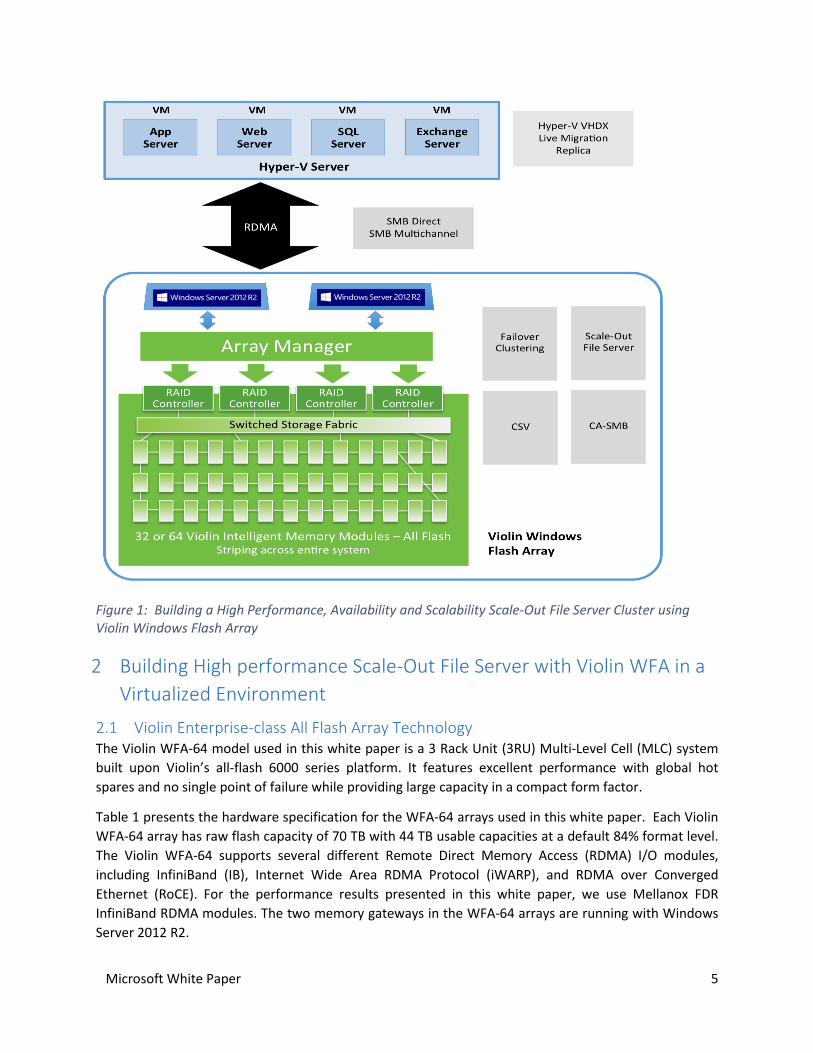
Violin Windows Flash Array (WFA) is a next generation All-Flash Array storage platform delivered by the
joint efforts of Microsoft and Violin Memory, providing built-in high performance, availability and
scalability. With the integration of Violin’s All Flash Array and Microsoft Windows Server 2012 R2 Scale-
Out File Server cluster, Violin WFA provides a tier-zero and tier-one storage solution for customer’s
mission critical applications in datacenters, , and the public and private cloud computing environments.
Figure 1 presents the overview of the Scale-Out File Server solution built using Violin WFA-64.
In this white paper, we discuss some of the scenarios and workloads that benefit from the capabilities
and the performance of the storage platform provided by Violin WFA. A good high value scenario is
Hyper-V using Scale-Out File Servers to store virtual disk files (VHD/VHDX) for VMs on remote storage
shares with inherent availability and scalability promises. With Violin’s enterprise-class all-flash storage,
Microsoft’s SMB Direct protocol and Microsoft Windows Server 2012 R2 storage features, the Violin
WFA-64 is well-suited as a file server solution when deploying Hyper-V over SMB.
This white paper demonstrates that synthetic virtualized IO workloads running in Hyper-V VMs can
linearly scale to over two million random read IOPS and over 8.6 GB/s sequential read bandwidth with
two Violin WFA-64 arrays in a Scale-Out File Server Cluster. In this platform, 99th percentile latencies of
4.5ms can be achieved at a load of 2 million random read IOPS. For simulated OLTP IO traffic, 99th
percentile latencies of 3.7-4ms can be achieved at a load of 1.15 million IOPS. The Violin WFA with its
high performance, availability and scalability can easily keep up with customer’s most demanding
application SLAs while providing increased density and efficiency in a virtualized environment.
Microsoft White Paper 5
Figure 1: Building a High Performance, Availability and Scalability Scale-Out File Server Cluster using Violin Windows Flash Array
2 Building High performance Scale-Out File Server with Violin WFA in a
Virtualized Environment
2.1 Violin Enterprise-class All Flash Array Technology The Violin WFA-64 model used in this white paper is a 3 Rack Unit (3RU) Multi-Level Cell (MLC) system
built upon Violin’s all-flash 6000 series platform. It features excellent performance with global hot
spares and no single point of failure while providing large capacity in a compact form factor.
Table 1 presents the hardware specification for the WFA-64 arrays used in this white paper. Each Violin
WFA-64 array has raw flash capacity of 70 TB with 44 TB usable capacities at a default 84% format level.
The Violin WFA-64 supports several different Remote Direct Memory Access (RDMA) I/O modules,
including InfiniBand (IB), Internet Wide Area RDMA Protocol (iWARP), and RDMA over Converged
Ethernet (RoCE). For the performance results presented in this white paper, we use Mellanox FDR
InfiniBand RDMA modules. The two memory gateways in the WFA-64 arrays are running with Windows
Server 2012 R2.

Microsoft White Paper 6
WFA-64
VIMM Count & VIMM Raw Capacity (60 + 4) x 1.1TB
Form Factor / Flash type 3U / MLC
Total Raw Capacity (TB) 70 TB
Usable Capacity (TB @ 84% format level) 44 TB
NAND Flash Interface PCI-e 2.0
I/O Connectivity IB, iWARP, RoCE
Memory Gateway OS Windows Server 2012 R2
Table 1. Violin WFA-64 Model Specification
The WFA architecture offers sub-millisecond latency and wide stripe vRAID accelerated switched flash
for maximum performance. Figure 2 presents an overview of the Violin Windows Flash Array
architecture. The system can be divided into the following blocks:
IO Modules: The Violin WFA’s IO modules support all current RDMA protocols, including
InfiniBand, iWARP and RoCE.
Active/Active Memory Gateways (MG): The built in Windows Server 2012 R2 offers ways to
easily build and configure Windows Fail-Over clustering across multiple Memory Gateways,
manage Windows Scale-Out File Server Role, and setup Continuously Available File Shares with
Cluster Shared Volume (CSV) support. Violin also provides a user friendly control utility to
manage storage disk LUN configurations for Violin storage devices.
vRAID Control Modules (VCM): The Violin WFA provides 4 Active-Active vRAID Control Modules
for full redundancy. The VCMs implement Violin Memory’s patented vRAID algorithm to manage
the flash modules in RAID mode. vRAID is specifically engineered for flash and highly optimized
for Violin’s all flash memory arrays. It delivers fabric level flash optimization, dynamic wear
leveling, advanced ECC for fine grained flash endurance management, as well as fabric
orchestration of garbage collection and grooming to maximize system level performance. vRAID
also provides Violin Intelligent Memory Module (VIMM) redundancy support and protects the
system from VIMM failures.
Flash Fabric Architecture: The Flash Fabric Architecture (FFA) implements dynamic hardware
based flash optimization. Violin’s VIMMs form the core building block of the FFA. The WFA-64
model uses 64 VIMMs with 60 active VIMMs plus 4 global hot spares. A single VIMM can contain
up to 128 flash dies. The 64 VIMMs implementation in the WFA-64 thus contains more than
8000 flash dies, managed as a single system by vRAID in the VCMs. Optimizing flash endurance,
data placement, and performance across such a large number of dies is the key to deliver
sustainable performance, low latency, and high flash endurance rate. The Violin Memory Flash
Memory Fabric can leverage 1000’s of dies to make optimization decisions.

Microsoft White Paper 7
Figure 2: High Level Overview of Violin Windows Flash Array
Beside performance and cost-efficiency, business critical tier-0 and tier-1 applications have high demand
on system reliability. The Violin WFA-64 provides multi-level redundancy with the capability to hot-swap
all active components. The system has redundancy at all layers for hot serviceability and fault tolerance.
Table 2 provides details for Violin WFA-64 redundancy each component layer.
Module Total
Fans 6
Power Supply 2
VIMM 64 (60 + 4 hot spares)
vRAID Controllers 4
Array Controllers 2
Memory Gateways 2
Table 2: Violin WFA-64 Multi-Level Redundancy
2.2 Next Generation All Flash Array with Full Integration of Windows Scale-Out File
Server Violin’s WFA-64 model is a next generation All-Flash Array with full integration of a Windows Scale-Out
File Server solution. Customers can set up, configure and manage their file server storage in the familiar
Windows environment using Windows native tools.
Flash Memory fabric
o 4x vRAID Control Modules
(VCM)
Array Control modules
o Fully redundant
o Controls flash memory
fabric
o System level PCIe
switching
Active/Active memory gateways
o Two Windows Server 2012
R2 gateways
o Failover Cluster
IO Modules
o RDMA Support
o InfiniBand, iWARP and
RoCE

Microsoft White Paper 8
The dual memory gateways inside the Violin WFA run Windows Server 2012 R2. Windows Server 2012
R2 supports SMB Direct (the SMB 3 transport layer for RDMA) through RDMA-enabled network cards.
With the ability to directly place reads and writes into memory of the receiving client node without CPU
activity, SMB Direct lowers latency and CPU consumption on both the client and server while delivering
high IOPS and bandwidth utilization to remote SMB file shares. Currently, SMB Direct supports
InfiniBand, iWARP and RoCE.
SMB Direct is compatible with SMB Multichannel to achieve load balancing and automatic failover. SMB
multichannel automatically detects multiple networks for SMB connections. It provides a simple and
configuration free way of dynamic Multiple-Path IO (MPIO) for SMB traffic. SMB multichannel offers
resiliency against path failures and transparent failover with recovery without service disruption. By
aggregating network bandwidth from multiple network interfaces, SMB multichannel also provides
much improved throughput. Server applications can then take full advantage of all available network
bandwidth, as well as making them more resilient to network failure. In this white paper, the memory
gateways for Violin WFAs have been configured with multiple InfiniBand RDMA network adapters. With
SMB multichannel, the Violin WFA can fully utilize the redundancy and capacity provided by those
adapters.
A failover cluster is a group of independent computers that work together to increase the availability
and scalability of clustered roles. If one or more of the cluster nodes fail, the services will automatically
failover to other node without disruption of service. The Scale-Out File Server (SOFS) role in Windows
Server 2012 R2 not only provides a continuously available SMB service, but also provides a mechanism
for clustered file servers in an active-active configuration to aggregate bandwidth across the cluster
nodes. In continuously available file shares, persistent file handles are always opened with write through
to guarantee that data is on stable storage and durable against cluster node failure, which matches to
the capabilities of an All-Flash Array such as the Violin WFA-64.
Operating against a SOFS, SMB clients are transparently directed to do their IO against their owner node
to achieve balancing around the cluster. Cluster Shared Volumes in a Windows Server 2012 R2 failover
cluster allow multiple nodes in the cluster to simultaneously access shared storage with a consistent and
distributed file namespace. Therefore, CSVs greatly simplifies the management of large number of LUNs
in a failover cluster.
For the performance testing performed for this white paper, we create a failover cluster across two
Violin WFA-64 arrays with the Scale-Out File Server role. This mode of operation is an asymmetric SOFS,
since each individual CSV is served by one WFA and pair of Violin Memory Gateways. The Scale-Out File
Server Cluster supports scaling up to four Violin WFA arrays, at the supported limit of eight file server
nodes (Violin Memory Gateways) per SOFS of both Windows Server 2012 and Windows Server 2012 R2,
with up to 280 TB raw flash capacity.
2.3 Scaling and Performance with Hyper-V Virtualization Solution Hyper-V in Windows Server 2012 R2 provides industry-leading scalability and virtualized storage
performance with host support for 320 logical processors, 4 TB of physical memory and 1,024 active
virtual machines per server host. Hyper-V cluster supports up to 64 nodes and 8,000 VMs per cluster.
Windows Server 2012 R2 supports large virtual machines, up to 64 virtual processors and 1 TB virtual
memory. Hyper-V VMs can take full advantage of the high performance, availability and scalability of
Microsoft White Paper 9
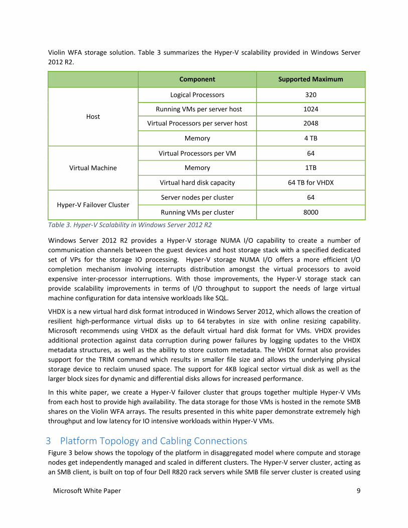
Violin WFA storage solution. Table 3 summarizes the Hyper-V scalability provided in Windows Server
2012 R2.
Component Supported Maximum
Host
Logical Processors 320
Running VMs per server host 1024
Virtual Processors per server host 2048
Memory 4 TB
Virtual Machine
Virtual Processors per VM 64
Memory 1TB
Virtual hard disk capacity 64 TB for VHDX
Hyper-V Failover Cluster Server nodes per cluster 64
Running VMs per cluster 8000
Table 3. Hyper-V Scalability in Windows Server 2012 R2
Windows Server 2012 R2 provides a Hyper-V storage NUMA I/O capability to create a number of
communication channels between the guest devices and host storage stack with a specified dedicated
set of VPs for the storage IO processing. Hyper-V storage NUMA I/O offers a more efficient I/O
completion mechanism involving interrupts distribution amongst the virtual processors to avoid
expensive inter-processor interruptions. With those improvements, the Hyper-V storage stack can
provide scalability improvements in terms of I/O throughput to support the needs of large virtual
machine configuration for data intensive workloads like SQL.
VHDX is a new virtual hard disk format introduced in Windows Server 2012, which allows the creation of
resilient high-performance virtual disks up to 64 terabytes in size with online resizing capability.
Microsoft recommends using VHDX as the default virtual hard disk format for VMs. VHDX provides
additional protection against data corruption during power failures by logging updates to the VHDX
metadata structures, as well as the ability to store custom metadata. The VHDX format also provides
support for the TRIM command which results in smaller file size and allows the underlying physical
storage device to reclaim unused space. The support for 4KB logical sector virtual disk as well as the
larger block sizes for dynamic and differential disks allows for increased performance.
In this white paper, we create a Hyper-V failover cluster that groups together multiple Hyper-V VMs
from each host to provide high availability. The data storage for those VMs is hosted in the remote SMB
shares on the Violin WFA arrays. The results presented in this white paper demonstrate extremely high
throughput and low latency for IO intensive workloads within Hyper-V VMs.
3 Platform Topology and Cabling Connections Figure 3 below shows the topology of the platform in disaggregated model where compute and storage
nodes get independently managed and scaled in different clusters. The Hyper-V server cluster, acting as
an SMB client, is built on top of four Dell R820 rack servers while SMB file server cluster is created using

Microsoft White Paper 10
four servers (memory gateways) built in two Violin WFA arrays. Every server node has two dual-port
InfiniBand RDMA network adapters installed and both ports of each adapter are used. The client and
cluster traffic between two clusters are routed through an FDR 56G InfiniBand fabric with a Mellanox
SX6036 FDR InfiniBand switch. Note: the actual usable bandwidth for FDR InfiniBand is 54G.
4-Node Hyper-V Server Cluster
Mellanox SX6036 56G IB RDMA Switch
Mellanox 56G IB FDR RDMA Card(x2 per server)
Mellanox 56G IB FDR RDMA Card(x2 per gateway)
Dell R820 Sandy Bridge Server Dell R820 Sandy Bridge ServerDell R820 Sandy Bridge Server Dell R820 Sandy Bridge Server
4-Node Scale-Out File Server Cluster
Violin WFA-64 (2 Gateways) Violin WFA-64 (2 Gateways)
Figure 3: Hyper-V Server & File Server Cluster Platform Topology in Disaggregated Model
3.1 Server Machines: Dell R820 We use Dell R820 as our SMB client machines. As the latest generation PowerEdge rack server offered
by Dell, the R820 with PCIe 3.0(8.0GT/s) support is a high performance platform designed for both
compute and storage intensive applications. The R820s being used in this report are powered by quad
Intel Xeon Sandy Bridge processors with highly scalable memory and ample I/O bandwidth which
enable it to readily handle very demanding and mission critical workloads in a wide range of
virtualization environments.
The family of Intel Sandy Bridge processors has embedded PCIe lanes for improved I/O performance
with reduced latency and support up to 160 lanes of PCIe 3.0 (40 per socket).

Microsoft White Paper 11
3.2 InfiniBand Fabric: Mellanox SX6036 Switch and ConnectX-3 VPI Network Adapter InfiniBand fabric helps to optimize the network efficiency making it a good fit for converged data centers
operating a wide range of applications. Mellanox’s FDR InfiniBand based solution for data centers and
high-performance computing systems includes ConnectX-3 adapters, SwitchX family of FDR InfiniBand
switches and FDR copper cables ensure high interconnect performance.
Mellanox Dual Port FDR InfiniBand ConnectX-3 adapter cards: Mellanox’s ConnectX-3 InfiniBand
adapters provide high performing and flexible interconnect solution. ConnectX-3 delivers up to
54Gb/s throughput across the PCI Express 3.0 host bus, enables fast transaction latency, less
than 1usec.
Mellanox SX6036 36-port FDR InfiniBand Switch: The SX6036 switch systems provide high
performing fabric solutions in a 1RU form factor by delivering 4.032Tb/s of non-blocking
bandwidth with 200ns port-to-port latency. Built with Mellanox's latest SwitchX-2 InfiniBand
switch device, these switches deliver up to 54Gb/s full bidirectional speed per port.
4 Hardware Configurations
4.1 Server Configurations Each Violin gateway (SMB server node) is a two socket server with dual Intel Sandy Bridge Xeon Hyper-
Threaded 8-core E5-2448L 1.80GHZ CPUs, 24G DDR3-1600 RAM, for 32 total Logical Processors. One
socket has the direct connection to the add-on PCI Express cards (RDMA NICs), and the other has the
direct connection to the NAND flash array.
The Violin WFA-64 gateway only supports PCIe 2.0(5.0GT/s) which is sufficient to drive the array itself.
The following screen copy shows the actual PCI Express link speed and width for each add-on Mellanox
RDMA NIC in the Violin gateway.
Figure 4: RDMA NIC hardware information in Violin gateways
The Hyper-V servers (SMB client nodes) are using the Dell R820 platform with Intel Sandy Bridge Xeon
E5-4650L 2.60GHZ and 256G (8G x 32) 1600MHZ RDIMM RAM. With Hyper-Threading enabled, we get
64 logical processors for every host with quad socket and 8 core per socket in the system. Table 4 shows
Dell R820 machine settings we chose for this report:
Settings Value
Windows (both host OS and guest OS) Power Options High Performance
CPU Settings in BIOS (ver 2.1.0)
Logical Processor(HT) Support Enabled
C-State Disabled
Turbo Boost Enabled
QPI Speed Maximum data rate (8.0GT/s)
Memory Settings in Memory Frequency Maximum speed
Microsoft White Paper 12
BIOS (1600MHZ)
Memory Operating Mode Optimizer
Node Interleaving Disabled(NUMA on)
Table 4. Server Machine BIOS and Power Settings
4.2 Network Configurations Mellanox SX6036 InfiniBand Switch:
MLNX-OS: SX_3.3.5006
Mellanox FDR InfiniBand Network Adapter:
Driver: 4.70.10126.0 and Firmware: 2.31.5050
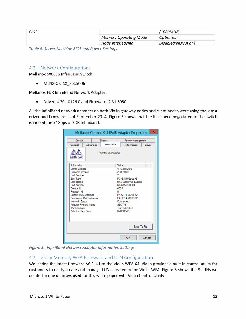
All the InfiniBand network adapters on both Violin gateway nodes and client nodes were using the latest
driver and firmware as of September 2014. Figure 5 shows that the link speed negotiated to the switch
is indeed the 54Gbps of FDR Infiniband.
Figure 5: InfiniBand Network Adapter Information Settings
4.3 Violin Memory WFA Firmware and LUN Configuration We loaded the latest firmware A6.3.1.1 to the Violin WFA-64. Violin provides a built-in control utility for
customers to easily create and manage LUNs created in the Violin WFA. Figure 6 shows the 8 LUNs we
created in one of arrays used for this white paper with Violin Control Utility.

Microsoft White Paper 13
Figure 6: Violin Control Utility to create and manage Violin vLUNs
5 Hyper-V and Scale-Out File Server Cluster Configuration Settings
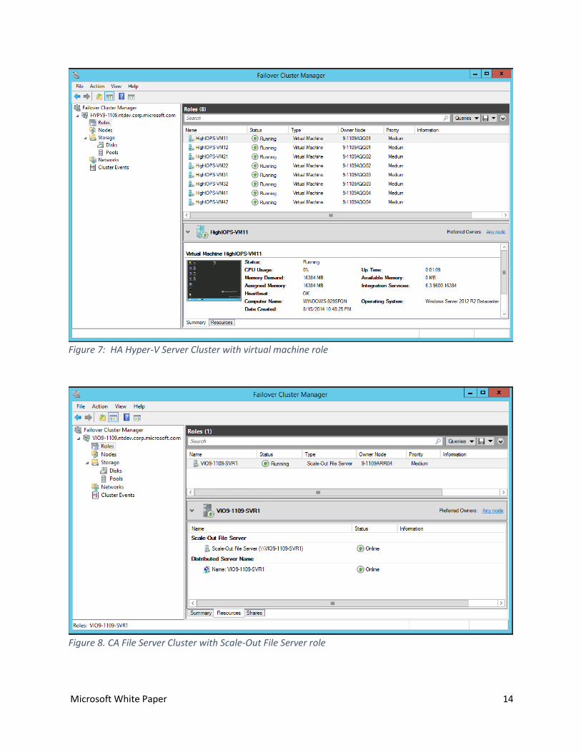
5.1 Overview of Hyper-V and Scale-Out File Server Clusters In this report, a Hyper-V server cluster \\HYPV9-1109 is created with virtual machine role configured to
enable running high availability VMs. A separate file server cluster \\VIO9-1109 is also created with
scale-out file server role configured to enable continuous availability SMB file shares.
Figure 7 and Figure 8 shows these two clusters and their configured roles.
Microsoft White Paper 14
Figure 7: HA Hyper-V Server Cluster with virtual machine role
Figure 8. CA File Server Cluster with Scale-Out File Server role
Microsoft White Paper 15
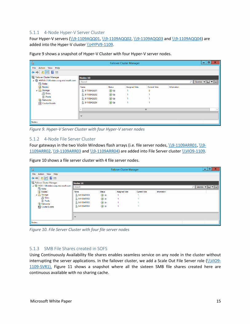
5.1.1 4-Node Hyper-V Server Cluster Four Hyper-V servers (\\9-1109AQQ01, \\9-1109AQQ02, \\9-1109AQQ03 and \\9-1109AQQ04) are
added into the Hyper-V cluster \\HYPV9-1109.
Figure 9 shows a snapshot of Hyper-V Cluster with four Hyper-V server nodes.
Figure 9. Hyper-V Server Cluster with four Hyper-V server nodes
5.1.2 4-Node File Server Cluster Four gateways in the two Violin Windows flash arrays (i.e. file server nodes, \\9-1109ARR01, \\9-
1109ARR02, \\9-1109ARR03 and \\9-1109ARR04) are added into File Server cluster \\VIO9-1109.
Figure 10 shows a file server cluster with 4 file server nodes.
Figure 10. File Server Cluster with four file server nodes
5.1.3 SMB File Shares created in SOFS Using Continuously Availability file shares enables seamless service on any node in the cluster without
interrupting the server applications. In the failover cluster, we add a Scale Out File Server role (\\VIO9-
1109-SVR1), Figure 11 shows a snapshot where all the sixteen SMB file shares created here are
continuous available with no sharing cache.

Microsoft White Paper 16
Figure 11. CA-SMB File Shares in the SOFS
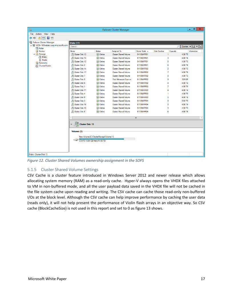
5.1.4 Shared Storage with CSV in the SOFS Cluster: Sixteen LUNs from two arrays are added to the cluster together with extra one (Cluster Disk 5) reserved
as quorum disk. CSV is added on top of every shared disk in the cluster except quorum. CSV is a
distributed file system access system to enable every node in the cluster to concurrently access a shared
volume. By using CSV, we can unify the storage access into a single namespace for ease management
and smooth VM migration purpose. Scale-Out File Server only supports CSV.
To avoid the performance hit of redirect I/Os, each node (memory gateway) in the file server cluster is
assigned the ownership of cluster storage volumes based on the affinity of physical storage. Figure 12 on
next page shows \\9-1109ARR01 owns Cluster Disk 2/12/13/15, \\9-1109ARR02 owns Cluster Disk
6/7/14/17, \\9-1109ARR03 owns Cluster Disk 1/4/9/11 and \\9-1109ARR04 owns Cluster Disk
3/8/10/16. Note: since sixteen LUNs come from two separate arrays (8 per array), you will see disk
numbers are duplicate from 1~8.
Microsoft White Paper 17
Figure 12. Cluster Shared Volumes ownership assignment in the SOFS
5.1.5 Cluster Shared Volume Settings CSV Cache is a cluster feature introduced in Windows Server 2012 and newer release which allows
allocating system memory (RAM) as a read-only cache. Hyper-V always opens the VHDX files attached
to VM in non-buffered mode, and all the user payload data saved in the VHDX file will not be cached in
the file system cache upon reading and writing. The CSV cache can cache those read-only non-buffered
I/Os at the block level. Although the CSV cache can help improve performance by caching the user data
(reads only), it will not help present the performance of Violin flash arrays in an objective way. So CSV
cache (BlockCacheSize) is not used in this report and set to 0 as figure 13 shows.

Microsoft White Paper 18
Figure 13. Cluster Shared Volumes settings
5.2 Network Configurations in SOFS Cluster: SMB Multichannel allows to use multiple network interfaces for better throughput and network fault
tolerance. In both traditional and scale-out file server clusters, to use the multiple paths simultaneously,
a separate subnet must be configured for every NIC for SMB Multichannel as Failover Clustering will only
use one IP address per subnet regardless the number of NICs on that subnet. Figure 14 shows four
subnets are used in this cluster (192.168.110.0, 192.168.120.0, 192.168.130.0, 192.168.140.0) which are
dedicated to four separate InfiniBand connections. Each InfiniBand network connection is assigned to
allow both cluster network communication and client traffic. Figure 15 shows each InfiniBand network
connection is owned by both nodes in the file server cluster.

Microsoft White Paper 19
Figure 14. Network Subnet Settings in SOFS
Figure 15. Network Connection Settings in SOFS
5.3 Cluster-Aware Updates (CAU) In Windows Server 2008 and Windows Server 2008 R2, patching a failover cluster means applying a fair
number of manual steps to update each server in the cluster during a specified maintenance window.
Introduced in Windows Server 2012, CAU provides a reliable and automated way that enables users to
update servers in a cluster with little or no loss of availability during the updating process. For
continuously available workloads such as Hyper-V with live migration or file server with SMB transparent
failover, CAU can coordinate cluster updates with no impact to the service availability. The screen copy
below shows CAU helps keep each node in the file server cluster up-to-date.

Microsoft White Paper 20
Figure 16. Cluster Aware Update Status for the File Server Cluster \\VIO9-1109
5.4 Software Configurations
5.4.1 Scale-Out File Server Cluster settings
5.4.1.1 Symmetric Storage vs. Asymmetric Storage
If the storage is equally accessible from every node in a cluster, it is referred to as symmetric meaning
that each node in the cluster can take ownership of storage in the case of node servicing or failure.
When using symmetric storage, the SMB clients will only connect to a single file server cluster node for
all the SMB shares. Common examples of symmetric storage are when the Scale-Out File Server is put in
front of a fiber channel SAN or using simple type Storage Spaces built on top of shared SAS. Distinct from
the presence of symmetric connections is the ability to do direct IO to storage from each connected
node in symmetric storage. A configuration where not every node has the ability to read/write to the
storage is called asymmetric. An example of asymmetric storage is using a mirrored storage space as
shared storage in a Scale-Out File Server Cluster, where reads and write must flow through the node
which owns the CSV resource.
In this report, the storage cluster created by the two Violin WFA arrays is asymmetric. If a storage cluster
is created only using a single Violin WFA array, it is considered as symmetric as direct IO is possible from
both nodes (memory gateways) within the same Violin WFA array. For both symmetric and asymmetric
storage, metadata operations (e.g. creating a new file) continue to go through the CSV resource owner
node.

Microsoft White Paper 21
5.4.1.2 SMB Witness Client
The following screen copy including the output of Get-SmbWitnessClient shows the SMB witness client
registration status in this file server cluster under active workloads. The witness node and file server
node associated with each client is different. This will get SMB traffic evenly distributed amongst
different server nodes to avoid a single server node becoming a bottleneck. If both clients happen to get
registered with the same witness node, using PowerShell cmdlet Move-SmbWitnessClient can help us
achieve active-active load balancing manually.
Figure 17. SMB Witness Client Registration Status
5.4.1.3 CA SMB Share
Figure 18 shows that every SMB Share is set to Continuous Availability with file caching off.
Figure 18. CA SMB Share information
5.4.2 Hyper-V VM Settings and Tuning up The Hyper-V virtual SCSI storage adapter used to only have a single VMBus channel to send requests and
receive response on single VM virtual processor, which can cause CPU bottlenecks within a VM under
intensive workloads. To overcome this, starting from Windows Server 2012, Hyper-V added VMBus
multi-channel (a.k.a. Hyper-V storage NUMA I/O) support in virtual SCSI controller. Each channel
provides a targeted interrupt and an additional ring buffer pair so the device can efficiently send SCSI
requests and receive responses on multiple virtual processors concurrently. Large number of channel

Microsoft White Paper 22
settings may cause excessive memory overhead. For that reason, Hyper-V caps the default number of
channels to a smaller value in proportion to the number of VM virtual processors. Table 5 lists the
default and maximum number of VMBus channels for a VM with different number virtual processor
configurations. For a large VM with 64 VPs and 4 virtual SCSI controllers, it is possible to configure up to
64 channels in total so that a single VM can effectively distribute the intensive workloads amongst all its
64 virtual processors. Since all VMs used here are configured with 16 virtual processors and one virtual
SCSI controller, they just have one VMBus channel by default which will in turn have just one virtual
processor to handle response (interrupt and DPC) upon I/O completion. In general, the default VMBus
channel setting is sufficient to handle most of the VM workloads. However, it is not enough for the
extremely high I/O rate used in our experiments here. To solve that issue, for each VM, we changed the
default number of channels from 1 to 4 which is the maximum allowed value for a 16 virtual processor
VM so we can have four virtual processors instead of one inside VM handling response in parallel. The
registry key set in VM is: HKLM\System\CurrentControlSet\Enum\VMBUS\{deviceid}\{instanceid}\Device
Parameters\StorChannel\ChannelCount:4 1.
Table 5. Hyper-V VMBus Multi-Channel Settings (per vSCSI)
DeviceID and InstanceID can be obtained from device instance path of virtual SCSI controller from device
manager within VM.
Figure 19. Device ID and Instance ID of VM SCSI Controller
1 More VM tunings can be found at Windows Server 2012 R2 Performance Tuning Guide for Hyper-V Servers: http://msdn.microsoft.com/en-us/library/windows/hardware/dn567657.aspx#storageio

Microsoft White Paper 23
In Windows Server 2012 R2, the Hyper-V IO Balancer is primarily designed to balance I/O traffic amongst
VMs running on non-shared storage from single host. In this report we turned off IO Balancer on each
Hyper-V host to avoid the potential performance hit (throughput drop and latency spike within VMs)
due to the I/O throttling of IO Balancer for VMs with VHDX files hosted on the remote SMB shares. The
registry key set on host is HKLM\SYSTEM\CurrentControlSet\Control\StorVSP\IOBalance\Enabled:0.
Figure 20 shows the VM settings for a VM running in the cluster HYPV9-1109 from Windows Failover
Cluster Manager UI. All the VMs use the same settings: each VM is configured with 16 virtual processors
(VP), one virtual NUMA, 16G RAM and one virtual SCSI controller with 16 VHDX data files attached. All
the VHDX files attached to the same VM are about 127GB fixed type and hosted on the same SMB file
share in a Scale-Out file server cluster.
Figure 20. Hyper-V VM Settings

Microsoft White Paper 24
6 Experimental Results
6.1 Benchmark Tool We use IOMeter (2008.06.22.RC2) as our primary I/O performance benchmarking tool in this report to
measure the IOPS and bandwidth. Results presented in section 6.3.1 to 6.3.3 are collected using the
IOMeter benchmarking tool. Here is a list of IOMeter settings we use for this report when running
workloads within VMs:
1 IOMeter manager
16 IOMeter worker threads
One worker per target (VHDX) and 16 targets per VM
o Warm-up time prior to measurements: 5 minutes
o Measurement run time: 5 minutes
Queue depth per thread: 64 for Random and 1 for Sequential workloads
The DISKSPD2 2.0.12 performance benchmarking tool was used for capturing latency measurement due
to its support for capturing high fidelity latency histograms. Equivalent settings were used, discussed in
more detail in presentation of those results. Results presented in section 6.3.4 are collected using the
DISKSPD benchmarking tool.
6.2 Test Workloads Different input data streams are used to get a good coverage for maximum performance in theory using
both monolithic and mixed workloads. I/Os are aligned to 4K size for better performance on NAND flash.
o Synthetic monolithic workloads
100% Random: 4K 100% Reads and 4K 100% Writes
100% Sequential: 512K 100% Reads and 512K 100% Writes
Note: 512K I/Os are popular SQL Server DSS (Decision Support Systems) workloads.
o Simulated server workloads
OLTP DB Mixed: 8K, 90% Read, 10% Write, 100% Random
Exchange Server Mixed: 32K, 60% Read, 40% Write, 80% Random, 20% Sequential
6.3 Violin Windows Flash Array Performance Data Table 6 lists the published Violin Windows Flash Array performance specification (physical unit). For
example, the maximum bandwidth a single Violin WFA-64 can sustain is 4GB/s which can be translated
into 1-Million IOPS for a 4K Random Reads.
2 DISKSPD is available as a binary and open source (MIT License) release. Binary: http://aka.ms/diskspd Source: http://github.io/microsoft/diskspd

Microsoft White Paper 25
Table 6. Violin WFA Performance Spec (Source: Violin Memory)
Our experimental results show we can fully achieve the published data from Hyper-V VMs running on
the SMB client side over the RDMA network. Table 7 summarizes the performance results achieved in
this platform for monolithic workloads and mixed type workloads. The Violin WFA array can linear scale
from one array to two arrays in terms of throughput and bandwidth.
Workload One Array Two Arrays Scaling Factor
4K 100% Random Read (IOPS) 1.08 Million 2.16 Million 2.0
4K 100% Random Write (IOPS) 810K 1.6 Million 2.0
512K 100% Sequential Read (Bandwidth) 4.3GB/s 8.6GB/s 2.0
512K 100% Sequential Write (Bandwidth) 3.1GB/s 6.2GB/s 2.0
OLTP: 8K, 90% Read, 10% Write, 100%
Random
550K (IOPS) 1.1 Million (IOPS) 2.0
4.4GB/s (Bandwidth) 8.8GB/s (Bandwidth) 2.0
Exchange Server: 32K 60% Read, 40%
Write, 80% Random, 20% Sequential
130K (IOPS) 260K (IOPS) 2.0
4.16GB/s (Bandwidth) 8.32GB/s (Bandwidth) 2.0
Table 7. Summary of Experimental Performance Results
Windows Flash Array Model WFA-64 WFA-48 WFA-32 WFA-24 WFA-16
Form Factor / Flash Type 3U / MLC 3U / MLC 3U / MLC 3U / MLC 3U / MLC
Raw Capacity (TB) 70 52 35 26 17
Usable Capacity (TB) @ 84% format 44 33 22 16 11
I/O Connectivity 10GbE, 56Gb IB 10GbE, 56Gb IB 10GbE, 56Gb IB 10GbE, 56Gb IB 10GbE, 56Gb IB
Max. 4KB IOPS 1M IOPS 1M IOPS 750k IOPS 750k IOPS 750k IOPS
Max. Bandwidth (100% Reads) 4GB/s 4GB/s 4GB/s 4GB/s 4GB/s
Nominal Latency <500 µsec <500 µsec <500 µsec <500 µsec <500 µsec
Microsoft White Paper 26
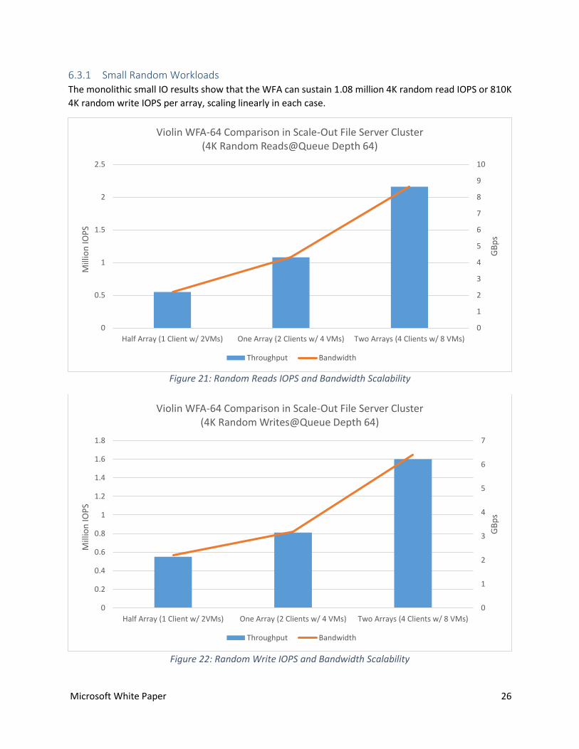
6.3.1 Small Random Workloads The monolithic small IO results show that the WFA can sustain 1.08 million 4K random read IOPS or 810K
4K random write IOPS per array, scaling linearly in each case.
Figure 21: Random Reads IOPS and Bandwidth Scalability
Figure 22: Random Write IOPS and Bandwidth Scalability
0
1
2
3
4
5
6
7
8
9
10
0
0.5
1
1.5
2
2.5
Half Array (1 Client w/ 2VMs) One Array (2 Clients w/ 4 VMs) Two Arrays (4 Clients w/ 8 VMs)
GB
ps
Mill
ion
IOP
S
Violin WFA-64 Comparison in Scale-Out File Server Cluster(4K Random Reads@Queue Depth 64)
Throughput Bandwidth
0
1
2
3
4
5
6
7
0
0.2
0.4
0.6
0.8
1
1.2
1.4
1.6
1.8
Half Array (1 Client w/ 2VMs) One Array (2 Clients w/ 4 VMs) Two Arrays (4 Clients w/ 8 VMs)
GB
ps
Mill
ion
IOP
S
Violin WFA-64 Comparison in Scale-Out File Server Cluster(4K Random Writes@Queue Depth 64)
Throughput Bandwidth

Microsoft White Paper 27
6.3.2 Large Sequential Workloads The 512K sequential read results show that the WFA maximum read bandwidth of 4.3 GBps is already
achieved by using half array. The maximum read bandwidth can linear scale to 8.6 GBps from one WFA
array to two WFA arrays.
Figure 23: Sequential Read Bandwidth Scalability
The 512K sequential write results show that the WFA maximum write bandwidth of 3.1 GBps is achieved
by using half array. The maximum writ bandwidth can linear scale to 6.2 GBps from one WFA array to
two WFA arrays.
Figure 24: Sequential Write Bandwidth Scalability
0
1
2
3
4
5
6
7
8
9
10
GB
ps
Violin WFA-64 Bandwidth Comparison in Scale-Out File Server Cluster(512K Sequential Reads@Queue Depth 1)
Half Array (1 Client w/ 2VMs) One Array (2 Clients w/ 4 VMs) Two Arrays (4 Clients w/ 8 VMs)
0
1
2
3
4
5
6
7
GB
ps
Violin WFA-64 Bandwidth Comparison in Scale-Out File Server Cluster(512K Sequential Writes@Queue Depth 1)
Half Array (1 Client w/ 2VMs) One Array (2 Clients w/ 4 VMs) Two Arrays (4 Clients w/ 8 VMs)
Microsoft White Paper 28
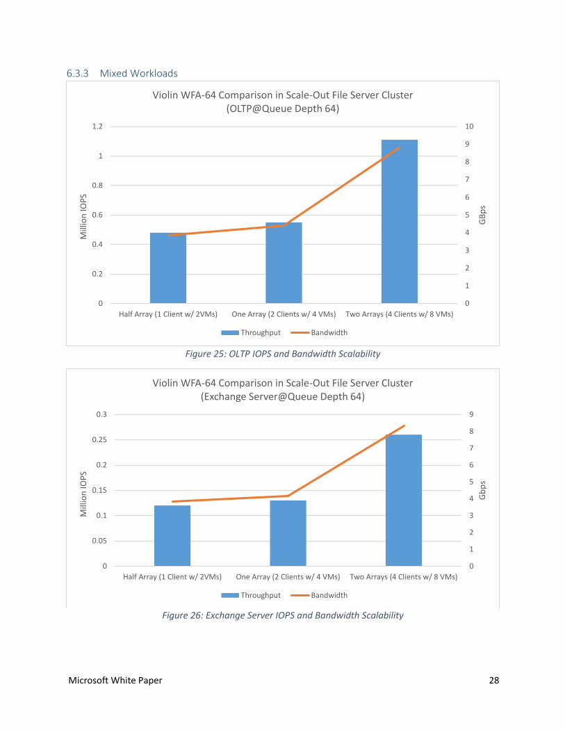
6.3.3 Mixed Workloads
Figure 25: OLTP IOPS and Bandwidth Scalability
Figure 26: Exchange Server IOPS and Bandwidth Scalability
0
1
2
3
4
5
6
7
8
9
10
0
0.2
0.4
0.6
0.8
1
1.2
Half Array (1 Client w/ 2VMs) One Array (2 Clients w/ 4 VMs) Two Arrays (4 Clients w/ 8 VMs)
GB
ps
Mill
ion
IOP
S
Violin WFA-64 Comparison in Scale-Out File Server Cluster(OLTP@Queue Depth 64)
Throughput Bandwidth
0
1
2
3
4
5
6
7
8
9
0
0.05
0.1
0.15
0.2
0.25
0.3
Half Array (1 Client w/ 2VMs) One Array (2 Clients w/ 4 VMs) Two Arrays (4 Clients w/ 8 VMs)
Gb
ps
Mill
ion
IOP
S
Violin WFA-64 Comparison in Scale-Out File Server Cluster(Exchange Server@Queue Depth 64)
Throughput Bandwidth
Microsoft White Paper 29
6.3.4 Latency The DISKSPD tool (see section 6.1, page 24) was used for data in this section due to its support for
capturing latency distributions. These distributions allow us to show the full latency profile of the end to
end IO channel from the Hyper-V Guest VMs through the SMB Direct RDMA network channel to the
WFA.
Two sets of results are presented:
4K random reads: extending the data in Figure 21 (page 26), a sweep of increasing IO load
leading up to the 2 million 4K read IOPS result
OLTP: extending the data in Figure 25 (page 28), a sweep of increasing IO load leading up to the
1.15 million IOPS result
Each measurement was taken over a two minute period, preceded by a two minute warmup. For
instance, the two minutes of 2 million IOPS would yield 240 million (2.4 x 10⁸) total measured IOs.
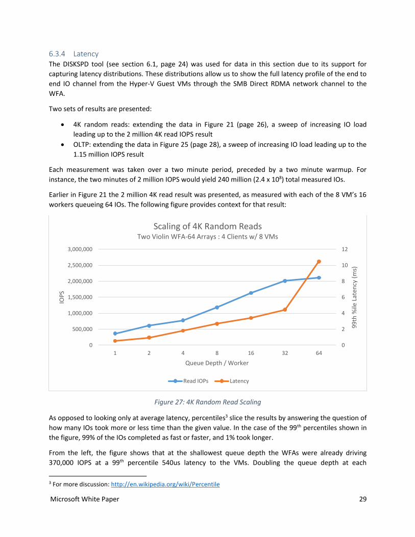
Earlier in Figure 21 the 2 million 4K read result was presented, as measured with each of the 8 VM’s 16
workers queueing 64 IOs. The following figure provides context for that result:
Figure 27: 4K Random Read Scaling
As opposed to looking only at average latency, percentiles3 slice the results by answering the question of
how many IOs took more or less time than the given value. In the case of the 99th percentiles shown in
the figure, 99% of the IOs completed as fast or faster, and 1% took longer.
From the left, the figure shows that at the shallowest queue depth the WFAs were already driving
370,000 IOPS at a 99th percentile 540us latency to the VMs. Doubling the queue depth at each
3 For more discussion: http://en.wikipedia.org/wiki/Percentile
0
2
4
6
8
10
12
0
500,000
1,000,000
1,500,000
2,000,000
2,500,000
3,000,000
1 2 4 8 16 32 649
9th
%ile
Lat
ency
(m
s)
IOP
S
Queue Depth / Worker
Scaling of 4K Random ReadsTwo Violin WFA-64 Arrays : 4 Clients w/ 8 VMs
Read IOPs Latency

Microsoft White Paper 30
subsequent point, the step to 64 shows a very significant increase in latency. This shows that the storage
stack was saturated and could not drive more IO. In fact, the WFAs were already driving their expected
~1M IOPS each (4GB/s) at a queue depth of 32 with 4.5ms 99th percentile latency. The increase to 64
provided a very slight improvement to IOPS but nearly tripled 99th percentile latency since all the IO
requests could do was queue behind the work already in flight.
The full distribution for each of the 8 VMs in the 32 queue depth case is shown in the following figure:
Figure 28 : 4K Random Read Latency near Saturation at 2 Million IOPS
These figures now put the 99th percentile in context, in a sweep from approximately 1.5-2.5ms between
the 20th and 80th percentile (over half of the total IO), and outlying latencies of between 15-25ms with a
few around 50ms affecting only two VMs. Although these outliers are significant, they stand up very well
to behavior for locally attached flash storage while at the same time providing the benefits of a scale out
shared storage architecture at over two million total IOPS.
Turning to OLTP, the following results repeat the OLTP data shown earlier in Figure 25 (page 28).
0
0.5
1
1.5
2
2.5
3
3.5
4
4.5
5
0 20 40 60 80 100
Late
ncy
(m
s)
Percentile
Latency of 4K Random Reads @ QD32Two WFA-64 Arrays : 4 Clients w/ 8 VMs to 99th %ile
05
101520253035404550
99
99
.9
99
.99
99
.99
9
99
.99
99
99
.99
99
9
99
.99
99
99
10
0
Percentile
Latency99th %ile - Max
Microsoft White Paper 31
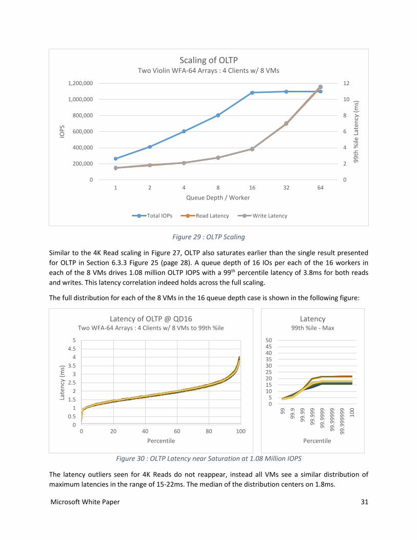
Figure 29 : OLTP Scaling
Similar to the 4K Read scaling in Figure 27, OLTP also saturates earlier than the single result presented
for OLTP in Section 6.3.3 Figure 25 (page 28). A queue depth of 16 IOs per each of the 16 workers in
each of the 8 VMs drives 1.08 million OLTP IOPS with a 99th percentile latency of 3.8ms for both reads
and writes. This latency correlation indeed holds across the full scaling.
The full distribution for each of the 8 VMs in the 16 queue depth case is shown in the following figure:
Figure 30 : OLTP Latency near Saturation at 1.08 Million IOPS
The latency outliers seen for 4K Reads do not reappear, instead all VMs see a similar distribution of
maximum latencies in the range of 15-22ms. The median of the distribution centers on 1.8ms.
0
2
4
6
8
10
12
0
200,000
400,000
600,000
800,000
1,000,000
1,200,000
1 2 4 8 16 32 64
99
th %
ile L
aten
cy (
ms)
IOP
S
Queue Depth / Worker
Scaling of OLTPTwo Violin WFA-64 Arrays : 4 Clients w/ 8 VMs
Total IOPs Read Latency Write Latency
0
0.5
1
1.5
2
2.5
3
3.5
4
4.5
5
0 20 40 60 80 100
Late
ncy
(m
s)
Percentile
Latency of OLTP @ QD16Two WFA-64 Arrays : 4 Clients w/ 8 VMs to 99th %ile
05
101520253035404550
99
99
.9
99
.99
99
.99
9
99
.99
99
99
.99
99
9
99
.99
99
99
10
0
Percentile
Latency99th %ile - Max

Microsoft White Paper 32
One simple example of translating this distribution to a workload is to consider an OLTP application
which consists of 3 IOs per operation. With the 99th percentile latency of approximately 5ms, only 1 in
100 IOs would take longer. Therefore, a service-level expectation that an OLTP operation would take less
than 15ms would be satisfied 1 – (1% x 1% x 1%) = 99.9999% of the time. Only one in one million
transactions would take longer, and would still be bounded by the very much less likely chance of all
three IOs taking the maximum 22ms.
With a total queue depth of 8 VMs x 16 Workers x 16 IOs = 1024 IOs in flight from the VMs to the WFA,
there is ample capacity in the system. This demonstrates the capability of the Scale out Windows Server
Hyper-V and Violin WFA solution to handle high intensity application loads.
7 Conclusion Violin Windows Flash Array (WFA) is a next generation All Flash Array. With the joint efforts of Microsoft
and Violin Memory, Windows Flash Array provides a tier-zero and tier-one storage solution for critical
applications which transforms the speed of business by providing high performance, availability and
scalability in a virtualized environment with low cost management. The results presented in this white
paper show the high throughput and low latency that can be achieved using Microsoft technologies
bundled with Violin hardware. With two Violin WFA-64 arrays, the workloads running in Hyper-V VMs
can linearly scale to over two million or 1.6 million IOPS for random reads or writes, 8.6 GB/s or 6.2GB/s
bandwidth for sequential reads or writes. Even at the maximum throughput of 2 million IOPS, the 99th
percentile latency can still be capped at 4.5ms and the latency of simulated OLTP IO traffic at a load of
1.15 million IOPS is capped at 3.7-4ms as well.
Reference
[1] Achieving over 1-Million IOPS from Hyper-V VMs in a Scale-Out File Server Cluster using Windows
Server 2012 R2: http://www.microsoft.com/en-us/download/details.aspx?id=42960
[2] Windows Storage Server Overview: http://technet.microsoft.com/en-us/library/jj643303.aspx
[3] Storage Quality of Service for Hyper-V: http://technet.microsoft.com/en-us/library/dn282281.aspx
[4] VHDX Format Specification: http://www.microsoft.com/en-us/download/details.aspx?id=34750
[5] Improve Performance of a File Server with SMB Direct: http://technet.microsoft.com/en-
us/library/jj134210.aspx
[6] Failover Clustering Overview: http://technet.microsoft.com/en-us/library/hh831579.aspx
[7] Windows Server 2012 R2 Performance Tuning Guide for Hyper-V Servers:
http://msdn.microsoft.com/en-us/library/windows/hardware/dn567657.aspx#storageio
[8] Scale-Out File Server Overview: http://technet.microsoft.com/en-us/library/hh831349.aspx
Microsoft White Paper 33
Acknowledgement We want to thank the following people from Microsoft and each team behind them for their great help
and support for this work:
Hyper-V: Rick Baxter, John Starks, Harini Parthasarathy, Senthil Rajaram, Jake Oshins
Windows Fundamentals: Brad Waters, Jeff Fuller, Ahmed Talat
File Server: Jim Pinkerton, Jose Barreto, Greg Kramer, David Kruse, Tom Talpey, Spencer Shepler
Windows Cluster: Elden Christensen, Claus Joergensen, Vladimir Petter
Windows Server and System Center: John Loveall, Jeff Woolsey
Windows Storage: Scott Lee, Michael Xing, Darren Moss
Networking: Sudheer Vaddi, Don Stanwyck, Rajeev Nagar
The authors would also like to thank our industry partners including Violin Memory and Mellanox for
providing their latest product samples to allow us to build the test infrastructure for the performance
experiments discussed in this paper. The product pictures used in this report are provided by courtesy of
them as well. Particularly we want to give our special thanks to the following people for their help:
Violin Memory: Joseph Slember, Bryan Billings, Clay Ryder
Mellanox: Motti Beck