Building Control Specification - Mark Sheehan Building ... for... · Building Control Specification...
43
1 | Page Building Control Specification New Dwelling 39 The Old Common Chalford Gloucestershire
Transcript of Building Control Specification - Mark Sheehan Building ... for... · Building Control Specification...

1 | P a g e
Building Control
Specification
New Dwelling
39 The Old Common
Chalford
Gloucestershire

2 | P a g e
Contents
Specialist Details ................................................................................................................. 6
Foundations .................................................................................................................................. 6 Beam and Block Floor ................................................................................................................. 6 Retaining Wall ............................................................................................................................. 6 Steel Beams .................................................................................................................................. 6 Glass Balustrading to Juliette balcony ......................................................................................... 6
SAP Calculations and Energy Performance Certificate ............................................................... 6 Water Consumption Calculation .................................................................................................. 6
Site preparation ................................................................................................................... 7
Foundations ......................................................................................................................... 7
Pre-Cast beam and block floor at higher level ..................................................................... 7
Solid Floor at Lower Level ................................................................................................... 8
DPM & Radon Protection ..................................................................................................... 9
External Walls ...................................................................................................................... 9
Retaining Walls ................................................................................................................................ 9
Construction ................................................................................................................................. 9
Damproofing ................................................................................................................................ 9 Insulation & Inner skin ................................................................................................................ 9
Cavity Walls ................................................................................................................................... 10
Cavity Tray ................................................................................................................................ 10
Mortar......................................................................................................................................... 10 Inner Leaf ................................................................................................................................... 11 Insulation to walls ...................................................................................................................... 11
Outer Leaf .................................................................................................................................. 11 Cavity Ties ................................................................................................................................. 11 Internal Finish ............................................................................................................................ 11
Insulated Cavity Closures .................................................................................................. 11
Internal Walls .................................................................................................................... 12
Block work Walls....................................................................................................................... 12
Studwork Walls .......................................................................................................................... 12 Wall between loft space and kitchen.......................................................................................... 13
Lintels ................................................................................................................................ 13
First Floor Construction...................................................................................................... 15

3 | P a g e
Joists ........................................................................................................................................... 15
Floor Boards ............................................................................................................................... 15 Strutting ...................................................................................................................................... 16 Plasterboard ................................................................................................................................ 16 Insulation .................................................................................................................................... 16
Notches & Holes ........................................................................................................................ 17 Lateral Restraint ......................................................................................................................... 18
Steel Beams ...................................................................................................................... 18
Roof Construction .............................................................................................................. 18
Roof over Kitchen .......................................................................................................................... 18
Roof over Bedroom / Bathroom..................................................................................................... 18
Roof over Entrance Lobby / Store ................................................................................................. 18
General ........................................................................................................................................... 19
Tiles ............................................................................................................................................ 19 Felt and Battens .......................................................................................................................... 19 Eaves and Gutters....................................................................................................................... 19
Roof Insulation to flat ceilings ................................................................................................... 19 Roof Insulation to sloping ceilings ............................................................................................ 20 Wall Plate Strapping .................................................................................................................. 20
Lateral Restraint ......................................................................................................................... 20
Plaster boarding.......................................................................................................................... 22 Rainwater Goods ........................................................................................................................ 22
Flashings and Cavity Trays ................................................................................................ 23
Windows ............................................................................................................................ 23
Fire Escape Windows................................................................................................................. 24
Rooflights ........................................................................................................................... 24
Doors ................................................................................................................................. 24
Internal Doors .................................................................................................................... 25
Background Ventilation ...................................................................................................... 25
Purge Ventilation ............................................................................................................... 26
Habitable Rooms ........................................................................................................................ 26 Kitchen ....................................................................................................................................... 26
Bathroom .................................................................................................................................... 26
Safety Glazing ................................................................................................................... 26
Staircase ............................................................................................................................ 27

4 | P a g e
Juliette Balcony Glazing..................................................................................................... 29
Solid Fuel Stove ................................................................................................................. 29
Appliance ................................................................................................................................... 29
Ventilation .................................................................................................................................. 29 Flue............................................................................................................................................. 30 Separation from combustible materials ...................................................................................... 30 Hearth Construction ................................................................................................................... 30 Notice Plate ................................................................................................................................ 30
Carbon Monoxide Alarm ........................................................................................................... 31 Test on Completion .................................................................................................................... 31
Above ground drainage...................................................................................................... 31
General ....................................................................................................................................... 31 WC ............................................................................................................................................. 32
Washbasin .................................................................................................................................. 33 Bath ............................................................................................................................................ 33 Shower ....................................................................................................................................... 33 Traps........................................................................................................................................... 33
Soil and Vent Pipe...................................................................................................................... 34
Below Ground Drainage..................................................................................................... 34
General ....................................................................................................................................... 34 Inspection Chambers .................................................................................................................. 35 Manholes Covers........................................................................................................................ 35
Surface Water .................................................................................................................... 35
Soakaways .................................................................................................................................. 35
Refuse Storage .................................................................................................................. 36
Fire Alarms ........................................................................................................................ 36
Access to and within the dwelling ...................................................................................... 37
Entrance Door ............................................................................................................................ 37 Ramped Approach...................................................................................................................... 37 Internal Doors ............................................................................................................................ 37
Electrical Installation .......................................................................................................... 38
Generally .................................................................................................................................... 38 Energy Efficient Lighting .......................................................................................................... 38 External Energy Efficient Lighting ............................................................................................ 39
Accessible switches and socket outlets ...................................................................................... 39

5 | P a g e
Heating and Hot Water ...................................................................................................... 39
General ....................................................................................................................................... 39 Hot & Cold Water Supply .......................................................................................................... 40 Supply of Bath Hot Water .......................................................................................................... 41
Low Temperature Hot Water Heating ....................................................................................... 41
Services ............................................................................................................................. 42
Sound Performance ........................................................................................................... 42
Pressure Testing ................................................................................................................ 42
Thermal Performance ........................................................................................................ 42
Provision of Information ..................................................................................................... 43

6 | P a g e
Specialist Details
The additional details / calculations are to be supplied by specialist sub-contractors and
submitted to Building Control for approval at the appropriate stages for the following:-
Foundations
Engineers calculations / details for the foundation design.
Beam and Block Floor
Full details / calculations for the suspended beam and block ground floor
Retaining Wall
Engineers calculations for the retaining wall
Steel Beams
Ridge beam over kitchen
Beams in lounge supporting wall above
Lintels where they will be subject loadings from beams.
Glass Balustrading to Juliette balcony
Full details / calculations of the glass balustrading including the fixing details.
SAP Calculations and Energy Performance Certificate
Design and As Built SAP Calculations along with an Energy Performance Certificate on
completion all to demonstrate compliance with the requirements of Part L.
Water Consumption Calculation
Water Consumption calculation to be submitted using appropriate software to demonstrate
with the requirements of Part G and Regulation 17K.
7 | P a g e
Site preparation
Remove any existing building structures such as foundations, drains, trees etc. as indicated
on drawings prior to construction of the proposed development.
Strip from oversite area all vegetation and top soil.
Foundations
Due to the split level arrangement of the house and the depth of dig the foundations must be
dug strictly in accordance with the Structural Engineers details.
All foundation depths to be agreed on site with the Building Control Officer and may
require adjustment should ground conditions dictate. A minimum of 24 hours’ notice to be
given to Building Control to enable them to inspect the foundation prior to any pouring of
concrete.
Pre-Cast beam and block floor at higher level
The area is to be treated with a proprietary weed killer to kill any vegetation.
Reduce levels to ensure that upon completion there is a minimum 150mm air gap between
the reduced ground level and the underside of the suspended pot and beam floor.
Pot & Beam suspended floor by specialist supplier bedded on a DPC all in accordance with
the manufacturer’s instructions.
Periscope vents to be provided giving ventilation equal to at least 1500mm2/m run of
external wall or 500mm2/m
2 of floor area, whichever gives the greater opening area.
Ventilation openings should incorporate suitable grilles which prevent the entry of vermin to
the sub-floor but do not resist the air flow unduly.

8 | P a g e
Grout the beams and provide a slurry concrete mix across the top of the floor to provide a
level base for the radon barrier.
Provide the Building Control Officer with a copy of the manufacturers design calculations.
Visqueen High Performance Radon Membrane extended across the cavity at dpc level
150mm Celotex insulation
500g polythene vapour barrier
18mm t& groove chipboard flooring (moisture resistant in kitchen)
Provide a cavity tray above the dpc with weep vents at 450mm centres.
Solid Floor at Lower Level
The area is to be treated with a proprietary weed killer to kill any vegetation.
Excavate to reduce levels as necessary.
150mm well consolidated hard core
Visqueen High Performance Radon Membrane extended across the cavity at dpc level
100mm concrete.
150mm Celotex insulation
500g polythene vapour barrier
18mm t& groove chipboard flooring
Provide a cavity tray above the dpc with weep vents at 450mm centres.
9 | P a g e
DPM & Radon Protection
Damp Proof membrane to be Visqueen High Performance Radon Membrane installed
strictly in accordance with the manufacturer’s instructions and taken across the cavity at dpc
level.
Provide a cavity tray above the dpc with weep vents at 450mm centres.
External Walls
Retaining Walls
Construction
The retaining wall to be designed by a structural engineer – anticipated construction
Two leaves of 100mm dense concrete Blockwork with a 150mm reinforced concrete cavity.
Back of wall to be lined with RIW Doubledrain linked to land drain at base of wall. Land
drain to connect into downpipes and there onto soakaway.
Back fill with free draining fill to engineer’s requirements.
Damproofing
Line inner face with one layer of RIW Sheetseal 226 linked to floor membrane at base. All
installed strictly in accordance with manufacturer’s instructions.
Insulation & Inner skin
Allow for a 100mm cavity construct 150mm Celcon Solar Blockwork wall with 50mm
Celotex clipped back to the Blockwork in the cavity.
Fill cavity between Celotex and Sheetseal with well compacted sand/cement fill.

10 | P a g e
13mm two coat plaster finish on room side.
Cavity Walls
The external wall construction to be:-
(a) 100mm facing brick (125 Cotswold stone on front elevation)
(b) 100mm insulation (see below)
(c) 100 insulation block (see below)
Below ground level use 7 N/mm2 concrete blockwork.
Fill cavities with Gen 1 (ST2) concrete up to 225mm below ground level dpc or as indicated
on the sections. Clean off surplus mortar from joints on cavity faces as work proceeds.
Keep cavities, ties and dpc’s free from mortar and debris at all times.
Cavity Tray
Build in cavity tray to act as DPC horizontally in cavity walls laid in continuous length on a
full even bed of fresh mortar with 100mm laps at joints and full laps at angles. Provide
weep vents at 450mm centres
Immediately lay at least one full course of masonry on a thin bed of fresh mortar. Keep
finished joint thickness as close to normal as practicable. Ensure continuity of dpc by
lapping with damp proof membrane of ground floor. Ensure that dpc ’s in external walls are
a minimum of 150mm above finished ground level and stepped to suit.
Mortar
Mortar to be designated mix to BS5268: part 3 (ii) below dpc level and (iii) above dpc level.
Do not carry up any one leaf more than 1.5m in any one day unless permitted by engineer.

11 | P a g e
Inner Leaf
100mm thick inner leaf Celcon Solar insulation block.
Insulation to walls
100mm Earthwool Dritherm 32 Ultimate by Knauff Insulation to incorporate 200mm of
rigid insulation as supplied by the manufacturer.
(Note that this is a high specification for the wall insulation but is a necessity to achieve
compliance with the SAP calculation, if a lower level of insulation is provided compliance
with the SAP calculation may not be achieved.)
Outer Leaf
100mm thick Celcon Standard block with render finish
Cavity Ties
Stainless steel wall ties sloped slightly downwards towards outer leaf with drip centred in
the cavity and pointing downwards. Do not bend ties to suit coursing. Evenly space at
600mm horizontally, staggered in alternate courses and at 450mm centres vertically.
Double up wall ties at all openings placing ties within 225mm of reveals. Provide final row
of wall ties maximum 150mm from wall plate level.
Internal Finish
Surface internal surface with 13mm thick plaster scrim and skim or 13mm thick
plasterboard on plaster dabs, scrim and skim finish.
Insulated Cavity Closures
Provide insulated cavity closure to all doors and windows with ties built into cavity wall and
fixed to door & window units. These will also act as vertical DPC.
A suitable closure for example would be Kooltherm Cavity Closure
fixed as shown below:-

12 | P a g e
Internal Walls
Refer to plans to see which walls will be block work and which ones will be studwork
Block work Walls
Block work walls to be Celcon Standard blocks.
Studwork Walls
Timber stud partitions to internal walls where indicated to be as follows:-
Studwork to be generally 50 x 90mm SC3 at 450mm vertical and 900mm horizontal centres.
Sole and head plates to be 75 x 90mm SC3.
Both sides of internal partitions to be finished with 12.5mm thick wallboard (density
15kg/m2) , scrim and skim.

13 | P a g e
Infill studs with 90mm thick fibreglass insulation with a minimum density of 10kg/m3.
Wall between loft space and kitchen
Block work wall to be Celcon Standard blocks.
Dot and Dab 75mm Celotex to face of wall in loft space and tape all joints with metallic foil
tape.
Lintels
Use Catnic or similar proprietary lintels installed strictly in accordance with manufacturer’s
instructions and suitable for intended spans.
A suitable lintel for the cavity walls being:-
Catnic Cougar Open Back

14 | P a g e
A suitable lintel for the internal loadbearing walls being:-
Catnic CN5X
A suitable lintel for the internal non-loadbearing walls being:-
Catnic CN102
Bed all lintols on mortar with a minimum bearing of not less than 150mm.
Provide cavity trays/dpc over all lintels if required with stop ends and weep holes at 900mm
centres with a minimum of two per cavity tray.
Refer to engineers details and architects plans where lintols are carrying additional loadings
and install beams/lintols in accordance with the engineers requirements.

15 | P a g e
First Floor Construction
Joists
Refer to detailed drawings for size and layout of floor joists
Joists to be supported by joists hangers at all locations unless indicated otherwise on the
plans.
Floor Boards
18mm thick tongue and groove floor boarding. Ensure boarding has a density of 15kg/m2.
Use moisture resistant boarding in bathrooms and shower rooms.
16 | P a g e
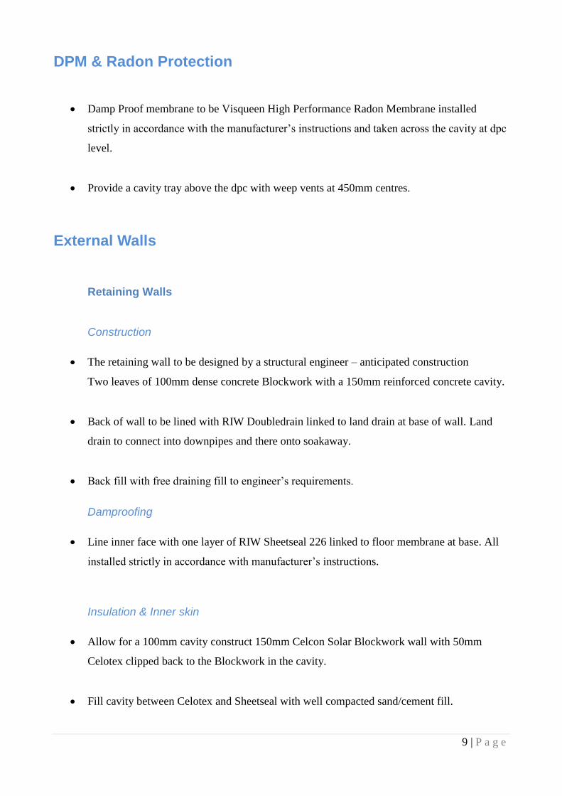
Strutting
Strutting to be provided in accordance with the following:-
Plasterboard
Surface underside of floor joists with one layer of 12.5mm thick Wall Board plasterboard by
Gyproc with joints taped and filled to give a half hour period of fire resistance.
Board to have a density of 15 kg/m3.
Insulation
Infill floor joists with 100mm thick fibreglass insulation as required for sound reduction.
Ensure fibreglass insulation has a minimum density of 10 kg/m3.
17 | P a g e
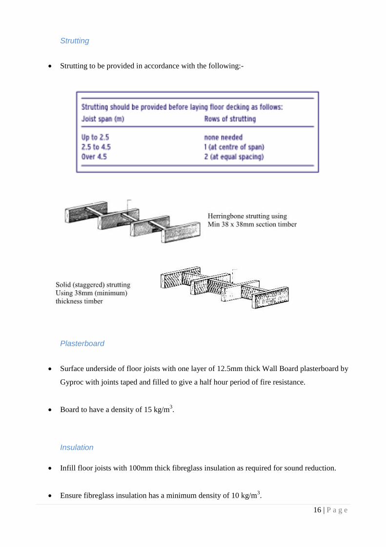
Notches & Holes
Notches should only be cut in accordance with diagram below:-
Holes should only be drilled in accordance with diagram below:-

18 | P a g e
Lateral Restraint
See diagrams and notes under roof construction
Steel Beams
All steel beams and associated supports to be designed by the Structural Engineer.
Beams supporting upper level to be either concealed within the floor void or plaster boarded
with 12.5mm plasterboard and skim plaster finish all to give 30 minutes fire resistance..
Roof Construction
Roof over Kitchen
This roof will have sloping ceiling and is to be designed by the Structural Engineer.
Refer to structural engineers details.
Roof over Bedroom / Bathroom
47 x 170mm C16 rafters at 450mm centres.
47 x 145mm C16 Ceiling Joists at 450mm centres
47 x 150mm C16 binder hung from ridge every 4th Rafter
Roof over Entrance Lobby / Store
47 x 150mm C16 rafters at 450mm centres.
47 x 150mm C16 Ceiling Joists at 450mm centres

19 | P a g e
General
Tiles
Tiles to be to the approval of the Local Planning Authority. Tiles to be fixed and lapped
strictly in accordance with the manufacturer’s instructions and to be suitable for the intended
pitch.
Felt and Battens
25 x 38mm softwood treated battens on 1 layer of Klober Permo Forte breather membrane.
Membrane to be sealed and lapped by 150mm and installed in compliance with the
manufacturer’s specification.
At eaves provide and fix Klober Universal Eaves Carrier under lapping the 1st width of
membrane by at least 150mm and dress into gutter.
Provide 25mm eaves vent to drain counter battens.
Ensure any water has a clear passage to extend into gutter.
Eaves and Gutters
100mm upvc gutter, laid to suitable falls on rise and fall brackets, discharging to 63mm
diameter down pipes in position shown on plan.
Provide facia & soffit board if required by Architect/Client/Planning Authority
Roof Insulation to flat ceilings
150mm of Crown Rockwool laid between the ceiling joists.
150mm of Crown Rockwool or similar insulation laid across the ceiling joists.

20 | P a g e
Roof Insulation to sloping ceilings
100mm of Celotex insulation between the rafters.
50mm of Celotex insulation on the underside of the rafters
12.5mm Plasterboard finish.
Wall Plate Strapping
50 x 100mm C16 wall plate strapped to inner leaf with 30 x 5mm mild steel galvanised
straps at least 1m in length at maximum 2m centres.
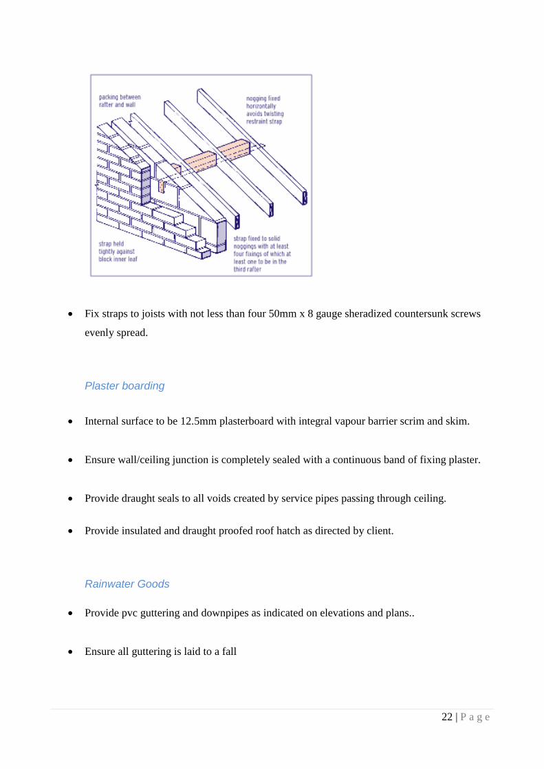
Lateral Restraint
Provide lateral restraint straps in accordance with the details below.
Provide Catnic or similar galvanised lateral restraint straps fixed to a minimum of three
floor joists, ceiling joists and rafters, not less than 30 x 5mm cross section, 150mm cranked
end and 1100mm long.
Position at not more than 2m centres to all floor joists, ceiling joists and rafters.

21 | P a g e
Ensure that cranked end is tight in contact with cavity face of wall inner leaf and is not
pointing upwards.
Fix noggins and packs beneath straps, where span of joists run parallel to wall. Noggins and
packs to fit tightly and be not less than three quarters of joist depth. Notch joists so that
straps fit flush with surface.
22 | P a g e
Fix straps to joists with not less than four 50mm x 8 gauge sheradized countersunk screws
evenly spread.
Plaster boarding
Internal surface to be 12.5mm plasterboard with integral vapour barrier scrim and skim.
Ensure wall/ceiling junction is completely sealed with a continuous band of fixing plaster.
Provide draught seals to all voids created by service pipes passing through ceiling.
Provide insulated and draught proofed roof hatch as directed by client.
Rainwater Goods
Provide pvc guttering and downpipes as indicated on elevations and plans..
Ensure all guttering is laid to a fall

23 | P a g e
Flashings and Cavity Trays
Provide Code 5 lead flashing around chimney flue.
Provide cavity trays with weep holes in the following locations:-
(a) Above the Radon Barrier at DPC level.
Windows
All windows achieve a U value of 1.4 w/m2k
(Note that this is a high specification for the windows but is a necessity to achieve
compliance with the SAP calculation, if a lower performing windows are used compliance
with the SAP calculation may not be achieved.)
All windows to be fitted with draught-proof seals.
Units to be provided with ventilation units and safety glazing as indicated in ventilation
section of this specification.
All windows to be fitted with openable lights as indicated on the elevations. All opening
lights to open to at least 30o.
Contractor to confirm opening sizes with manufacturer prior to manufacture but opening
light must be equal to 1/20th
of the floor area of the room in which it is located.
Contractor to confirm structural opening sizes prior to construction of building.

24 | P a g e
Fire Escape Windows
Study on the lower level to have a “Fire Escape Window” i.e. to have an unobstructed
opening of at least 450mm x 750mm for fire escape purposes. Bottom edge of window
opening light to be between 800 and 1100mm above finished floor level.
Rooflights
All roof lights to achieve a U value of 1.3 w/m2k
(Note that this is standard specification for a Velux Rooflight)
Client to choose type of roof light e.g. centre pivot / top hung / electronic controls etc.
All roof lights to include manufacturers flashing kits appropriate to the pitch of roof.
Rafters to be trimmed out as shown on the roof layout.
Doors
All external door units to achieve a U value of 1.6 w/m2k or better.
Entrance door to be 932mm wide with a disabled threshold. Ensure door has a minimum
clear opening of 775mm.
All doors to be fitted with draught-proof seals.
Units to be provided with ventilation units and safety glazing as indicated in ventilation
section of this specification.
Contractor to confirm structural opening sizes prior to construction of building.
25 | P a g e
Internal Doors
All internal doors on the ground floor are to have a minimum clear opening width of 750mm
All internal doors should have a 10mm gap under the door to ensure good air transfer
throughout the dwelling.
Background Ventilation
The total background ventilation required for the dwelling is 50,000mm2. When ordering the
windows & doors the manufacturer must be made aware of this requirement and background
ventilation should be provided to all windows to ensure that this total is achieved. (This
requirement is suitable for houses with any air test result – if the air pressures test result is
more than 5 then 35,000mm2 will be acceptable.
Given that there are 13 windows & roof lights (exc porch) to the house approx. 3847mm2
per window will achieve 75,000mm2
Notwithstanding the total requirement each room must have at least 5000mm2 and 2500mm
2
to wet rooms (bathroom/en-suite/kitchen)
Background Ventilation by Velux roof lights is as follows:-
Up to 550mm wide = 2200mm2
Up to 660mm wide = 3500mm2
Up to 780mm wide = 4300mm2
Up to 942mm wide = 5400mm2
The background vents (if not incorporated within the windows/doors must be located to
avoid draughts e.g. typically 1.7m above floor level.

26 | P a g e
Purge Ventilation
Habitable Rooms
Rapid ventilation is provided through openable windows as shown on the plans and
elevations with an openable area of at least 1/20th
of the floor area and with some part of the
opening at least 1.75m above floor level as shown on elevations.
(Minimum 5000mm2 background ventilation to be provided to each room but note the total
background ventilation required elsewhere)
Kitchen
Rapid ventilation to be provided by either 30 l/sec cooker hood extraction or 60 l/sec extract
fan, both terminating externally.
(Minimum 2500mm2 background ventilation to be provided)
Bathroom
Rapid ventilation is to be provided by mechanical extract fan capable of extracting at a rate
of at least 15 l/sec, which may be operated intermittently and has an over-run period of 15
minutes. Termination should be at roof level through a suitable tile vent or through external
walls.
(Minimum 2500mm2 background ventilation to be provided)
Safety Glazing
Toughened safety glazing to be provided at areas where glazing occurs less than 800mm
above floor level or external ground levels. Also where glazing occurs less than 1500mm

27 | P a g e
above floor level or external ground level within 300mm of any internal or external doors,
as indicated on plans and elevations.
See diagram below for clarification:-
The following locations also require safety glazing:-
Window on staircase if the glazing is within 800mm of the pitch line.
Staircase
The rise and going to comply with the following:-
o Maximum rise of 220mm
o Minimum going of 220mm
o Max pitch of 42o
o Twice the rise + the going must be between 550 and 700mm
o Minimum 50mm going on tapered treads
Provide a handrail to one side of the staircase.
Handrail to be at a height of between 900mm measured to the top of the handrail from the
pitch line of the stairs. At floor level and landing height of handrail to be 1000mm.

28 | P a g e
Handrails to be agreed with client.
Landings to be equal to the width of the staircase.
Landing space equal to width of staircase to be provided at top and bottom of the staircase.
Guarding to open side of stairs and landings to be agreed with client.
Provide vertical balusters to stairwell guarding with a 99mm maximum gap between them.
Ensure a minimum 2000mm headroom over pitch line of stairs and landing areas.
Any doors adjacent to staircase must be sited in accordance with the following diagrams:-
29 | P a g e
Juliette Balcony Glazing
The glazing is to be designed by specialist contractor.
Height must be at least 1100mm above the finished floor level. At this height it should be
designed such that it will resist a horizontally uniformally distributed line load of
0.74kN/m. Fixings at decking level must also resist the turning moment induced by the
above loading.
Recommended 15mm Toughened glass but must be confirmed by balustrade designer.
There must be no gaps greater than 99mm.
The balustrading must be designed such that it cannot be climbed upon.
Solid Fuel Stove
Appliance
The appliance is to be to the client’s choice and installed by a HEATAS engineer.
The appliance is to be a closed appliance with a flue draught stabiliser.
Ventilation
Permanently open vents to be provided equivalent to 850mm2 per KW of appliance rated
output.
The vents must be permanently open and non-adjustable and positioned where they are
unlikely to become blocked.
Location to be agreed with client but in locations where the occupants will not be provoked
into sealing them against draughts and noise.
They must be located outside fire place recess.
30 | P a g e
Flue
A twin wall insulated flue is to be provided.
For an appliance up to 30kW rated output burning any fuel use 150mm diameter or
rectangular/square flues having the same cross sectional area and a minimum dimension not
less than 125mm.
For an appliance more than 30kW but less than 50kW rated output burning any fuel use
175mm diameter or rectangular/square flues having the same cross sectional area and a
minimum dimension not less than 150mm.
Flue to terminate as shown on the plans at least as high as the ridge.
Separation from combustible materials
Floor joists and roof timbers to be minimum 50mm from outer face of flue.
Hearth Construction
125mm Non-combustible hearth top surface to finish at least 12mm above the surface of the
finished floor.
Hearth to extend at least 300mm in front of the appliance and 150mm at the sides.
Notice Plate
Notice plate displaying essential information on the flue and appliance must be provided.
The plate must be robust, indelibly marked and securely fixed in an unobtrusive but obvious
position within the building. (e.g. next to the electricity consumer unit, next to the water
supply stopcock)

31 | P a g e
Carbon Monoxide Alarm
A Carbon Monoxide Alarm complying with BS EN 50291:2001 powered by a battery
designed to operate for the working life of the alarm must be provided.
It must be located in the same room as the appliance:-
(a) On the ceiling at least 300mm from any wall or if it is located on a wall, as high
up as possible( above any doors and windows) but not within 150mm of the
ceiling and
(b) Between 1m and 3m horizontally from the appliance.
Test on Completion
The flue must be checked on completion to show that it is free from obstructions,
satisfactorily gas tight and constructed of materials and components of sizes which suit the
intended application.
A certificate confirming the above has been undertaken must be supplied to Building
Control on completion.
Above ground drainage
General
Install pipes, fittings and accessories in accordance with BS 5572 so that appliances drain
quickly, quietly and completely at all times and discharge is conveyed without cross flow,
back fall, leakage or blockage.
Obtain all components for each type of pipe work from the same manufacturer unless
specified otherwise.

32 | P a g e
Provide access fittings and rodding eyes as necessary in convenient locations to permit
adequate cleaning and testing of pipe work.
Provide for thermal and building movement when fixing and jointing, and ensure that
clearances are not reduced as fixing proceeds. Where not specified otherwise use plated,
sherardized, galvanised or non-ferrous fastenings, suitable for the purpose and background,
and compatible with the material being fixed or fixed to.
Comply with restrictions on the cutting of holes, chases, notches, etc. line with additional
supports as necessary at junctions and changes in direction. Fix every length of discharge
stack pipe at or close below the socket collar.
Make changes in direction of pipe runs only where shown on drawings unless otherwise
approved.
Cut ends of pipes to be clean and square with burrs and swarf removed.
Test upon completion of system, temporarily seal open ends of pipe work with plugs.
Connect a “U” tube water gauge and pump air into pipe work until gauge registers 38mm.
Allow a period for temperature stabilisation, after which the pressure of 38mm is to be
maintained for not less than 3 minutes. Test to be approved by Local Building Control
Officer.
WC
110mm diameter at a minimum slope of 18mm/m and maximum slope of 90mm/m for pipe
work up to 6m in length.

33 | P a g e
Washbasin
32mm diameter pipes at minimum slope of 18mm/m and maximum slope of 22mm/m for
pipe work up to 1.7m in length and 40mm diameter pipes at a minimum slope of 18mm/m
and maximum slope of 44mm/m for pipe work up to 3m in length and 50mm diameter pipes
at a minimum slope of 18mm/m and maximum slope of 44mm/m for pipe work up to 4m in
length.
Bath
40mm diameter pipes at a minimum slope of 18mm/m and maximum slope of 90mm/m for
pipe work up to 3m in length and 50mm diameter pipes at a minimum slope of 18mm/m and
maximum slope of 44mm/m for pipe work up to 4m in length.
Washbasin to be fitted with Marley Monitor ant-siphon bottle trap, fitted with cleaning eye.
Rodding points to be provided to all discharge pipes, which can not be reached by removing
traps. Ensure adequate access is provided to all cleaning eyes and rodding points. Provide
branch connections to soil pipes connecting to stub stack. All pipe work to be installed to
comply with manufacturer’s instructions and recommendations.
Shower
A fixed shower must be provided over the bath in order to comply with the Water Efficiency
Calculation.
Traps
Traps to Washbasins, Sinks and urinal to be 75mm deep and WC to be 50mm.
34 | P a g e
Soil and Vent Pipe
All above ground waste and soil drainage shall be constructed of upvc by Marley Extrusions
or similar to comply with BS 5572:1978.
Constructed of 100mm diameter upvc by Marley Extrusions or similar to comply with BS
5572. Boxed in within building with 12.5mm plasterboard and skimmed with 5mm plaster,
fixed on timber grounds. Screw on access to be provided as necessary to comply with
current regulations and recommendations.
SVP to terminate at ridge vent tile
Ensure roofing membrane is water tight where vent pipe passes through the roof.
Below Ground Drainage
General
Refer to site plan for details. The drainage layout is to be deemed provisional until the exact
layout is known on site following the excavations for the foundations. An alternative
drainage layout may be possible.
New foul drainage to connect to foul water sewer.
Drainage runs constructed of Osma UPVC or similar 100mm diameter pipes with flexible
joints. Pipes at a minimum 1:40 fall on minimum 100mm granular bed in single size pea
grave or aggregate to BS 982 nominal size 10mm. After testing backfill with selected
material free from vegetable matter, rubbish, frozen soil, stones and lumps retained by a
40mm sieve. Lay and compact in layers not exceeding 150mm.
Provide lintel or sleeve protection to drains passing through walls and foundations and leave
a minimum 50mm clear space around pipe. Ensure space around pipe is masked with rigid
sheeting.

35 | P a g e
Allow for differential settlement at all manholes by way of an extra flexible joint.
Inspection Chambers
450mm diameter pre-formed plastic inspection chamber and benching by Osma or similar
maximum 900mm deep.
Provide 150mm concrete bed and surround to Inspection Chambers.
Make pipe work connections as indicated on drawing and provide stop caps to unused
branches.
The maximum depth of Inspection Chamber to be 1200mm.
Manholes Covers
All covers to be grade A in Parking Areas and grade B in other locations.
Surface Water
Soakaways
Soakaways to be provided as indicated on the site plans
Size of soakaways to be subject to site conditions.
Soakaways to be located a minimum of 5m from all buildings and 2.5m from the boundary.
Provide rubble filled soakaways with a minimum of 1m3 below the incoming pipe. Fill with
free draining material such as clean broken bricks, crushed rock or gravel, size range
150mm to 50mm.
36 | P a g e
Line bottom and sides of soakaways with Geotextile membrane and [provide one top layer
of geotextile membrane before connecting inlet pipe to soakaway.
Provide inspection covers if required or backfill to finished ground level with as dug
material.
Refuse Storage
A 1.2m x 1.2m area is to be set aside within the gardens for refuse storage.
It must be sited within 25m of the Local Authority Collection point
Must not interfere with pedestrian or vehicle access and be away from any windows and
ventilators.
It should preferably be sited in a shady area.
Fire Alarms
Provide smoke alarms in the downstairs hallway and first floor landing.
Alarms to be 300mm from walls and light fittings and not located over heaters.
Alarms to be mains powered with a battery backup and conform to BS 5446-1:2000
Alarms to be interconnected within the house.
Ensure system compliance with BS 7671 (The IEE Wiring Regulations).
Smoke alarms to be placed within 7.5m of all doors to habitable rooms.
37 | P a g e
Access to and within the dwelling
Entrance Door
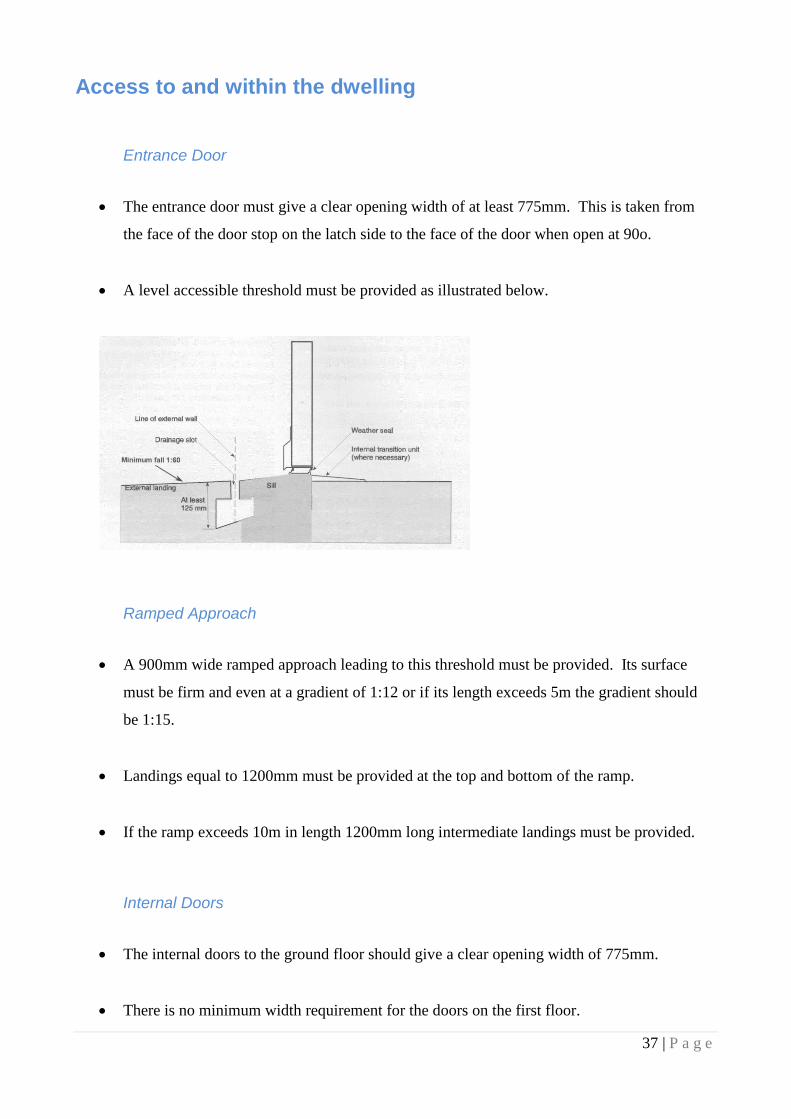
The entrance door must give a clear opening width of at least 775mm. This is taken from
the face of the door stop on the latch side to the face of the door when open at 90o.
A level accessible threshold must be provided as illustrated below.
Ramped Approach
A 900mm wide ramped approach leading to this threshold must be provided. Its surface
must be firm and even at a gradient of 1:12 or if its length exceeds 5m the gradient should
be 1:15.
Landings equal to 1200mm must be provided at the top and bottom of the ramp.
If the ramp exceeds 10m in length 1200mm long intermediate landings must be provided.
Internal Doors
The internal doors to the ground floor should give a clear opening width of 775mm.
There is no minimum width requirement for the doors on the first floor.

38 | P a g e
Electrical Installation
Generally
The electrical installation must be designed and installed in accordance with BS 7671:2008
incorporating Amendment No 1:2011.
Sufficient information must be provided within the dwelling to ensure that people can
operate, maintain or alter an electrical installation safely, this includes:-
(a) Electrical Installation Certificates or reports describing the installation and giving
details of the work carried out.
(b) Permanent labels, for example on earth connections and bonds, and on items of
electrical equipment such as consumer units and residual current devices.
(c) Operating instructions and logbooks.
Types and positions of fittings to be agreed with contractor’s installer and Client.
Lighting and power to be separately controlled circuits as follows with further subdivision
where necessary to ensure compliance with BS 7671.
Liaise with the Electrical Supply Company as necessary to ensure suitability of supply and
earthing arrangement, and to ensure connection when required.
All installations to be tested and after satisfactory completion of tests copies of completion
certificates to be submitted to the Client and Building Control
Energy Efficient Lighting
Three out of four light fittings to have low energy fittings with lamps having a luminous
efficacy greater than 45 lamp lumens per circuit-watt and a total output greater than 400
lamp lumens. (these may be dedicated fittings or standard fittings supplied with low energy

39 | P a g e
lamps. Light fittings whose supplied power is less than 5 circuit-watts are excluded from
this requirement)
External Energy Efficient Lighting
Any external lighting to have lamp capacity not greater than 100 lamp-watts or lamp
efficacy greater than 45 lumens per circuit-watt and to be automatically controlled so as to
switch off when lighting is not required.
Accessible switches and socket outlets
This applies the ground, first & second floors. They must be located in accordance with the
following diagram:-
Heating and Hot Water
General
Provide new hot water and heating system using a gas combination condensing boiler which
has a SEDBUK efficiency of 90% or better.
Any choice of alternative boiler with a reduced SEDBUK rating must be referred back to the
building designer for checking. This is VERY IMPORTANT!
40 | P a g e
Boiler to be sited with terminal at least 600mm from any opening into the dwelling.
Ensure all gas appliances and pipe work are installed to comply with current Codes of
Practice and British Standards and installed by an Approved Contractor.
Commissioning Certificate to be provided upon completion.
Hot & Cold Water Supply
Complete the design and install the systems to comply with BS6700 and be free from leaks
and water hammer.
All installation work to be carried out by qualified operatives.
Electrical work in connection with the installation must be in accordance with BS 7671
All locations where moisture is present or may occur, use corrosion resistant fittings/fixings
and avoid contact between dissimilar metals by use of suitable washers etc.
All equipment, pipe work, components, valves etc to be fully accessible for maintenance,
repair or replacement.
Installation to be fitted with vents at high points and draining taps at low points to facilitate
purging and draining.
Provide insulated hot water vessel if required complying with BS 1566 or BS 3198.

41 | P a g e
Supply of Bath Hot Water
To the bath provide an in-line blending valve or other appropriate temperature control
device to limit the temperature of the bath water to 48oC
Low Temperature Hot Water Heating
Provide fully automatic and independent temperature, time and zone control of the system.
Ensure that all controls are compatible with each other and with the central heating boiler.
The system must allow for separate heating zones to the living and sleeping accommodation
in accordance with the Domestic Heating Compliance Guide published by the Office of the
Deputy Prime Minister.
Complete the design, install and balance the system so that it complies with the water supply
byelaws/regulations, and is safe, efficient, and free from leaks, excessive noise and
vibration.
All installation work to be carried out by qualified operatives.
Electrical work in connection with the installation must be in accordance with BS 7671
Comply with restrictions on the cutting of holes, chases, notches etc in floor joists.
All locations where moisture is present or may occur, use corrosion resistant fittings/fixings
and avoid contact between dissimilar metals by use of suitable washers etc.
All equipment, pipe work, components, valves etc to be fully accessible for maintenance,
repair or replacement.
Installation to be fitted with vents at high points and draining taps at low points to facilitate
purging and draining.

42 | P a g e
Provide radiators connected to heating system. Location and number of radiators to be
agreed with installer.
Services
Provide Telephone, Gas, Water and Electric supplies to new dwelling.
Ensure all new services to be installed comply with current Codes of Practice and British
Standards.
Refer to site layout plan for known approximate lines of services.
Sound Performance
The specification for the internal floors and walls must be adhered to in order to ensure
adequate sound insulation within the dwelling/extension is achieved.
Pressure Testing
Upon completion a “Pressure Test” will need to be undertaken on the dwelling and the
results submitted to the Building Control Authority for approval. Refer to the Design SAP
calculation for the Pressure Test Result required.
Thermal Performance
The specification for the insulation and heating systems must be adhered to as they are
crucial to the CO2 emission rate calculation for the building demonstrating compliance with
the Building Regulations. A calculation has been carried out demonstrating compliance but
an “as built” calculation must also be provided following completion and this must also
meet the minimum standard.

43 | P a g e
If for any reason alternative materials/systems are used they must be referred back to the
Building Designer for checking.
Provision of Information
The owner of the building and the Building Control Authority are to be provided with
commissioning certificates for the heating and hot water systems.
The owner of the building is to be provided with a suitable set of operating and maintenance
instructions for the building services. These will need to include details for the timing and
temperature setting controls and any routine maintenance required.
A copy of the Energy Performance Certificate is to be provided for the owner and Building
Control.
A checklist signed by the installing HEATAS engineer to show that the wood burning
appliance has been installed in accordance with the requirements of Part J.
All electrical installations to be tested and after satisfactory completion of tests copies of
completion certificates to be submitted to the Client and Building Control