Building Construction -...
47
Building Construction 6 Dr Nabil El-Sawalhi Associate professor Engineering Projects Management
Transcript of Building Construction -...
Building Construction 6
Dr Nabil El-Sawalhi
Associate professor
Engineering Projects Management

Concrete Columns
• These are the vertical load bearing members of the structural frame which transmits the beam loads down to the foundations.
• They are usually constructed in storey heights and therefore the reinforcement must be lapped to provide structural continuity.

• COLUMNS
• Established design guides allow for reinforcement of between 0„8% and 8% of column gross cross sectional area. A lesser figure of 0„6% may be acceptable. A relatively high percentage of steel may save on concrete volume, but consideration must be given to the practicalities of placing and compacting wet concrete. If the design justifies a large proportion of steel,

• Transverse reinforcement ~ otherwise known as binders or links. These have the purpose of retaining the main longitudinal reinforcement during construction and restraining each reinforcing bar against buckling.
• Typical RC Column Details
• Steel Reinforced Concrete - a modular ratio represents the amount of load that a square unit of steel can safely transmit relative to that of concrete.


Beams
• These are horizontal load bearing members which are classified as either main beams which transmit floor and secondary beam loads to the columns or secondary beams which transmit floor loads to the main beams.
• Concrete being a material which has little tensile strength needs to be reinforced to resist the induced tensile stresses which can be in the form of ordinary tension or diagonal tension (shear). The calculation of the area, diameter, type, position and number of reinforcing bars required is one of the functions of a structural engineer.


Types of concrete Slabs
• Site-cast reinforced-concrete framing systems consist of horizontal elements (elevated floor/ roof slabs and beams) and vertical elements (columns and walls). Approximately 80% to 95% of the cost of materials and formwork of a concrete structural frame is in the horizontal framing elements of the frame.
• Consequently, the choice of the elevated floor system is the most important item in a concrete structure.
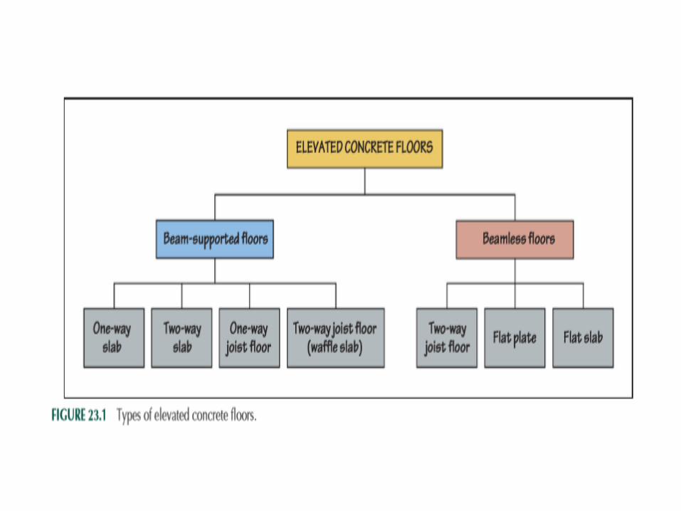
• Elevated concrete floor systems can be classified as (a) beam-supported floors and (b) beamless floors. They are further divided into several types, Figure 23.1

Beam Supported concrete Slabs
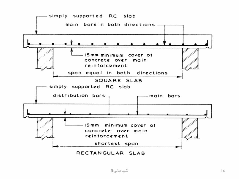
• A reinforced-concrete floor slab with beams on all four sides can either be a one-way slab or a two-way slab
• They are also called one-way solid slabs or two-way solid slabs to distinguish them from one-way Hollow Block slabs or two-way Hollow Block slabs, which are not completely solid. The transfer of loads from a solid slab to the four supporting beams is represented approximately by 45° lines originating from the slab corners, Figure 23.2 (a).
• If the slab panel is a square, each supporting beam receives the same amount of load, F igure 2 3.2( b).
• If the slab panel is rectangular, one pair of beams carries a greater load than the other pair.


ONE-WAY SOLID SLAB
• If the ratio of the long dimension to the short dimension of a four-side-supported slab panel is greater than or equal to 2.0, most of the load on the slab is transferred to the long pair of beams, that is, the load path is along the short dimension of the slab panel, Figure 23.2 (c).
• The load path along the long dimension of the slab is negligible. Because the load is effectively transferred along one direction in Figure 23.2 (c), the slab behaves as a one-way slab. The reinforcement in a one-way slab is placed along the short direction, referred to as the primary reinforcement to distinguish it from the nominal reinforcement placed along the perpendicular direction, called the secondary reinforcement .
• The purpose of secondary reinforcement is to resist stresses caused by concrete shrinkage and thermal expansion and contraction of the slab.
9تشييد مباني 14

TWO-WAY SOLID SLAB
• I f the ratio of the long to the short dimension of a four-side-supported slab panel is less than 2.0, the slab is considered to behave as a two-way slab .
• However, real two-way slab behavior occurs when the ratio of the two dimensions is as close to 1.0 as possible (between 1.0 and 1.25).
• In a two-way slab, both directions participate in carrying the load. Reinforcement is, therefore, provided in both directions as primary reinforcement. Although not common, both one-way and two-way slabs may occur in the same floor, Figure 23.3 .


9تشييد مباني 17
BEAM-AND-GIRDER FLOORS
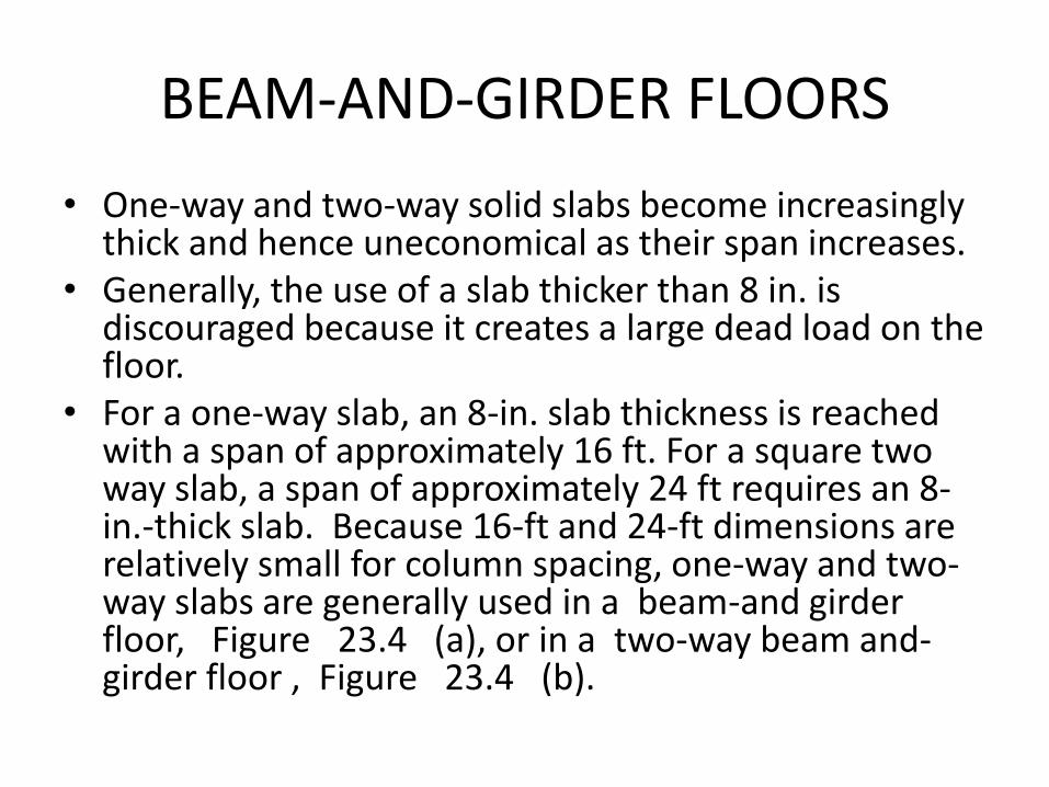
• One-way and two-way solid slabs become increasingly thick and hence uneconomical as their span increases.
• Generally, the use of a slab thicker than 8 in. is discouraged because it creates a large dead load on the floor.
• For a one-way slab, an 8-in. slab thickness is reached with a span of approximately 16 ft. For a square two way slab, a span of approximately 24 ft requires an 8-in.-thick slab. Because 16-ft and 24-ft dimensions are relatively small for column spacing, one-way and two-way slabs are generally used in a beam-and girder floor, Figure 23.4 (a), or in a two-way beam and-girder floor , Figure 23.4 (b).


BAND BEAM FLOOR • A concrete floor that cannot be constructed with a flat form
deck becomes uneconomical. Therefore, the floor systems shown in Figure 23.4 are relatively uncommon because of the complexity of the formwork resulting from deep beams around slab panels.
• one-way slab floor with wide and shallow, continuous beams, referred to as band beams (in contrast with the conventional narrow beams ), gives more economical formwork, Figure 23.5 .
• Because the beams are wide, the slab span is reduced, reducing the slab thickness. Additionally, because the beams are shallow, the floor-to-floor height is smaller, reducing the height of columns, interior partitions, and exterior cladding.
• A smaller floorto-floor height also reduces the overall height of the building, which reduces the magnitude of lateral loads on the building


ONE-WAY JOIST FLOOR • A concrete floor that results from extremely economical
formwork consists of closely spaced, narrow ribs in one direction supported on beams in the other direction, Figure 2 3.6.
• Because the ribs are narrow and closely spaced, the floor resembles a wood joist floor. It is, therefore, called a joist floor or a ribbed floor , but it is more commonly known as a one-way joist floor to distinguish it from the two-way joist floor described later.
• A one-way joist floor is constructed with U-shaped pans as formwork placed over a flat form deck.
• The gap between the pans represents the width of the joists, which can be adjusted by placing the pans closer together or farther apart, F igure 2 3.7.
•
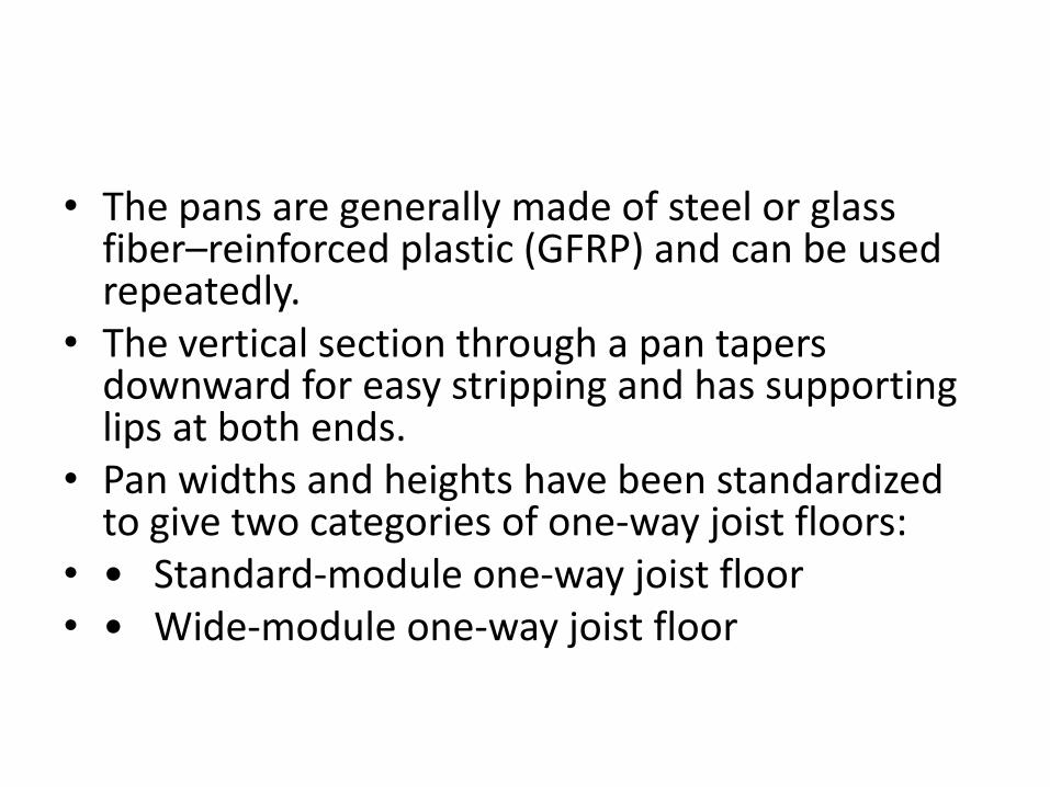
• The pans are generally made of steel or glass fiber–reinforced plastic (GFRP) and can be used repeatedly.
• The vertical section through a pan tapers downward for easy stripping and has supporting lips at both ends.
• Pan widths and heights have been standardized to give two categories of one-way joist floors:
• • Standard-module one-way joist floor • • Wide-module one-way joist floor
9تشييد مباني 24

STANDARD-MODULE ONE-WAY JOIST FLOOR
• Standard-module pans are 20 in. and 30 in. wide, F igure 2 3.8.
• These dimensions have been standardized so that, with 4-in.- and 6-in.-wide joists, the center-to-center spacings between joists are 2 ft and 3 ft, respectively. A slab thickness of 31 2 in. is often used (to provide a 1-h fire-rated floor), although structural considerations require a minimum thickness of only 2 in. with 20-in. pans and 21 2 in. with 30-in. pans. The slab is designed as a one-way slab resting on the joists, which, in turn, are designed as beams.


TWO-WAY JOIST FLOOR (WAFFLE SLAB)
• A two-way joist floor, also called a waffle slab , consists of joists in both directions, F igure 2 3.13. For the same depth of joists, a waffle slab yields a stiffer floor than a one-way joist floor. It is, therefore, used where the column-to-column spacing lies between 35 and 50 ft. A waffle slab is best suited for square or almost square column-to-column bays. When left exposed to the floor below, the waffle slab provides a highly articulated ceiling.

9تشييد مباني 28


Beamless concrete floor
• waffle slab is more commonly constructed as a beamless slab, F igure 2 3.15. In a beamless waffle slab, a few domes on all sides of a column are omitted so that the thickness of the slab at the columns is the same as the depth of the joists. The thickening of the slab at the columns provides shear resistance (against the slab punching through the columns).

FLAT PLATE
• A flat plate consists of a solid slab supported directly on columns, Figure 23.16 . A flat plate is similar to a two-way banded slab, except that the beam bands in both directions are concealed within the thickness of the slab. Therefore, the spans that can be achieved economically with a flat-plate floor are smaller than those obtained from one-way or two-way joist floors. Flat-plate slabs are suitable for occupancies with relatively light live loads, such as hotels, apartments, and hospitals, where small column-to-column spacing does not pose a major design constraint. Additionally, a drop ceiling is not required in these occupancies and HVAC ducts can be run within the corridors, where a lower ceiling height is acceptable.


• A flat-plate slab results in a low floor-to-floor height, and its formwork is economical. Because the beams are concealed within the slab thickness, columns need not be arranged on a regular grid—a major architectural advantage. However, a flat plate is a two-way system; hence, the column spacing in both directions should be approximately the same. A slab thickness of approximately 6 in. is generally needed for 15-ft * 15-ft column bays and approximately 8 in. for 20-ft * 20-ft bays with residential loads.

9تشييد مباني 35

9تشييد مباني 36

FLAT SLAB
• A flat slab is similar to a flat plate, but it has column heads, referred to as drop panels , Figure 2 3.17( a). The primary purpose of drop panels is to provide greater shear resistance at the columns, where the shear maximizes.


• Structurally, the drop panel must extend a minimum of one-sixth of the slab span in each direction, and its drop below the slab must at least be 25% of the slab thickness, F igure 2 3.17( b). For formwork economy, the drop depth is also based on lumber dimensions, Figure 23.17 (c). With round columns, however, manufacturers supply column forms that have built-in drop panels and column capitals, Figure 23.18 . A flat slab is generally used where the live loads are relatively high, such as in parking garages or storage or industrial facilities.


Precast Concrete
• Precast concrete members are fabricated in a precast plant and transported to the construction site for assembly.
• Precasting, which is generally done in covered or sheltered spaces, is particularly helpful in climates that limit the use of site-cast concrete.
• Additionally, because precasting is done at the ground level, the cost of formwork and shoring is considerably reduced.
• Formwork cost reduction is also achieved through the use of standard-size elements cast in permanent forms,

• Precasting also allows greater quality control over the strength of concrete and surface finishes. Most surface finishes are more easily obtained in a precast plant than at the site—often several floors above ground.
• Precast concrete has many disadvantages.
• Its main disadvantage is the cost of transportation. Although precast members are generally lighter than corresponding site-cast members (because of prestressing), they are still fairly heavy. Transportation also limits the length and width of precast members

• Another disadvantage of precasting is the need for heavier hoisting equipment at the construction site and additional safety measures that must be observed during erection.
• Erection and assembly at the site also introduce the need for a more skilled workforce compared with site-cast concrete construction.
• Architecturally, the most limiting factor in the use of precast concrete is the difficulty in sculpting concrete at a large scale, which is more easily realized with site-cast concrete.
• Precast elements are generally straight, with standard profiles.