BUILDING & COMMISSIONING OF A Prusa Mendel i2 · PDF fileBUILDING & COMMISSIONING Prusa Mendel...
85
Steven Flores California Polytechnic State University, San Luis Obispo B U I L D I N G & C O M M I S S I O N I N G O F A Prusa Mendel i2 Fused Deposition Modeling 3D Printer RepRap
Transcript of BUILDING & COMMISSIONING OF A Prusa Mendel i2 · PDF fileBUILDING & COMMISSIONING Prusa Mendel...

Steven FloresCalifornia Polytechnic State University, San Luis Obispo
B U I L D I N G & C O M M I S S I O N I N GO F A
Prusa Mendel i2Fused Deposition Modeling 3D Printer
RepRap

This text will document the building and commissioning of a Prusa Mendel i2 Fused Deposition Modeling 3D printer. The purpose of this document is to provide the user with a comprehensive guide to creating a fully opera-tional 3D printer, complete with a parts acquisition list, price breakdown, visual instructions, software list/links, and printing/troubleshooting tips. The concept behind this project is to further establish the operational simplicity and low cost of building and using one of the most popular RepRap printers, the Prusa Mendel i2.
i
© 2013 Steven Flores
ABSTRACT
A D V I S O R
Dr. Robert Crockett
G E N E R A L E N G I N E E R I N G D E PA R T M E N T
California Polytechnic State University
San Luis Obispo
December 2013

ii
Table of Contents
1 Parts AcquisitionParts Acquisition 4
1.1 Printed Parts 5
1.2 Hardware 9
1.3 Electronics 15
1.4 Cost Analysis 18
2 Build InstructionsBuild Instructions 19
2.1 Frame Triangles 20
2.2 Rear Threaded Rods 22
2.3 Front Threaded Rods 24
2.4 Top Threaded Rods 26
2.5 Frame Tightening 28
2.6 X-Axis 30
2.7 Y-Axis 32
2.8 Z-Axis 35
2.9 X-Carriage and Extruder 40
2.10 Electronics 43
3 SoftwareSoftware 51
3.1 Firmware 52
3.2 Host Software 59
3.3 G-Code Generation Software 63
3.4 Modeling Software 72

iii
4 Printing & TroubleshootingPrinting & Troubleshooting 76
4.1 Calibration 77
4.2 Troubleshooting 80
4.3 Surface Finish 81
5 Improvements & UpgradesImprovements & Upgrades 83
6 ReferencesReferences 84

PARTS ACQUISITION1Included in this list is the name (and item number where applicable) of the part, from where it was sourced (with a link where available), and the item(s) cost. Following this list is a project cost breakdown that should give the user an idea of a general total cost for all items required to build a complete and fully functioning Prusa i2 printer. (For more information on parts, see the Prusa i2 index page on the RepRap wiki: http://reprap.org/wiki/Prusa_Mendel).
A majority of the components were purchased through eBay, as many of these parts are very easily sourced from China among other countries, especially with the “Buy It Now” option. Keep in mind products coming from overseas may take multiple weeks to arrive, so plan accordingly. The global nature of the site is very helpful, along with the fact you will see the actual product pictured rather than a stock photo most of the time (it is usually easy to tell). The eBay search terms used are given below, as direct links will become useless after the auction ends. In some cases, if the seller operates a regularly stocked eBay store, their username will be given. Other products purchased elsewhere will have the working website posted, or the physical store location.
Lastly, all product prices noted are what I paid to receive the item. The item may have had free shipping within CONUS, or the price may reflect an added shipping fee from the item’s location of origin. Clearly the prices will have some slight vari-ance due to location, so keep that in mind when developing a budget of your own.
❖ denotes non-essential, but recommended components
4

5
1 Bar Clamp - x8 pcs
Included with complete set of Prusa i2 printed
Source:
eBay.com search terms: prusa i2
2 Bearing Guide – 3 sets
Might be included with complete set of Prusa i2 printed parts.
Note: can be substituted with M8x30mm fender washers (x6)
Source:
eBay.com search terms: prusa i2
3 X-Belt Clamps - x2 pcs
Included with complete set of Prusa i2 printed parts.
Source:
eBay.com search terms: prusa i2
4 Y-Belt Clamps – x2 pcs
Included with compete set of Prusa i2 printed parts.
Source:
eBay.com search terms: prusa i2
5 Couplers – 2 sets (x2 pcs ea)
Included with complete set of Prusa i2 printed parts.
Note: can be substituted with aluminum 5x8mm z axis couplers.
Source:
ebay.com search terms: prusa i2
6 Endstop Holders – x3 pcs
Included with complete set of Prusa i2 printed parts.
Note: Sometimes included with purchase of mechanical endstops.
Source:
ebay.com search terms: prusa i2
1.1 · Printed Parts - Total Cost: $48.40

7 Frame Vertex – x2 pcs
Included with complete set of Prusa i2 printed parts.
Source:
eBay.com search terms: prusa i2
8 Frame Vertex w/ Foot – x4 pcs
Included with the complete set of Prusa i2 printed parts.
Source:
eBay.com search terms: prusa i2
9 X-Carriage
Included with the complete set of Prusa i2 printed parts.
Alternate part: X-Carriage with 4 LM8UU bearing and 2 30mm fan mounts – designed by engineglue
Source:
eBay.com search terms: prusa i2
Thingiverse.comItem# 18899
10 X-End Idler
Included with the complete set of Prusa i2 printed parts.
Alternate part: Improved LM8UU version – designed by jonaskuehling
Source:
eBay.com search terms: prusa i2
Thingiverse.comItem# 18384
11 X-End Motor Mount
Included with the complete set of Prusa i2 printed parts.
Alternate part: Improved LM8UU version – designed by jonaskuehling
Source:
eBay.com search terms: prusa i2
Thingiverse.comItem# 18384
12 Y-Motor Bracket
Included with the complete set of Prusa i2 printed parts.
Alternate part: Improved version can be used without idler bearing – designed by ChrisMagno
Source:
eBay.com search terms: prusa i2
Thingiverse.comItem# 21716
6

13 Y-Bushing – x4 (or 3)
Included with the complete set of Prusa i2 printed parts.
Note: You can use only 3 bushing mounts on the Heated Build Platform if you prefer (4 will provide more stability).
Source:
eBay.com search terms: prusa i2
14 Z-Motor Mount – x2
Included with the complete set of Prusa i2 printed parts.
Alternate part: Integrated bar clamp – designed by theodleif
Source:
eBay.com search terms: prusa i2
Thingiverse.comItem# 11838
15 Z-Mount Clamp – x2
Included with the complete set of Prusa i2 printed parts.
Note: Unnecessary if using the alternate part design by theodleif above
Source:
eBay.com search terms: prusa i2
16 Wade’s Extruder Body
Included with the complete set of Prusa i2 printed parts.
Alternate Part: Reloaded version with guidler and tilt-screws – designed by jonaskeuhling
Source:
eBay.com search terms: prusa i2
Thingiverse.comItem# 18379
17 Wade’s Extruder Large Gear
Included with the complete set of Prusa i2 printed parts.
Alternate Part: Reloaded version included with alternate extruder body – designed by jonaskeuhling
Source:
eBay.com search terms: prusa i2
Thingiverse.comItem# 18379
7

8
18 Wade’s Extruder Small Gear
Included with the complete set of Prusa i2 printed parts.
Alternate Part: Reloaded version included with alternate extruder body – designed by jonaskeuhling
Source:
eBay.com search terms: prusa i2
Thingiverse.comItem# 18379

9
1 M8x60mm Hobbed Bolt
Bolt is hobbed for use with 3D printers. Teeth can be created at various distances along bolt shaft to ensure alignment with the filament feeder hole in the extruder body. For this project, teeth were created 29mm from hex head.
Cost: $6.50
Source:
eBay.com search terms: hobbed bolt prusa mendel reprap
Purchased from eBay user: easyreprap
2 608ZZ Bearings – 6 pcs
6 VXB 608ZZ bearings, used for extruder body as well as bearing guides.
Cost: $6.95
Source:
eBay.com search terms: 608zz vxb bearings reprap
Purchased from eBay user: crussell_1991
3 LM8UU Linear Bearing – 12 pcs
2 LM8UU bearings used for X-Idler and X-Motor mount (each). 4 LM8UU bearings used for X-Carriage. 4 LM8UU bearings used for HBP platform. Note: standard Prusa i2 parts list requires only 10 LM8UU linear bearings (X-Carriage and HBP platform each only use 3 LM8UU bearings)
Cost: $7.00
Source:
eBay.com search terms: LM8UU 8mm linear ball bearing
Purchased from eBay user: coolcheapworld
4 Aluminum GT2 Pulley and belt – 2 pcs
Sold as pair of aluminum pulleys with one 2 meter length of fiberglass reinforced, 20 tooth, 2mm pitch belt (to be cut in two by the user). Although the pulleys (and even the belts) can be 3D printed, these components dictate the accuracy with which your printer will operate, and must be high quality (and are therefore worth the expense).
Cost: $23.95
Source:
eBay.com search terms: aluminum gt2 20t pulley
Purchsed from eBay user: rp_one_labs
1.2 · Hardware - Total Cost: $153.62

5 M8 Hex Nuts - x100 pcs
1.25mm pitch. Exact number used in project is 82, but it may be easier to buy a 100 ct box. Note, you will also need 1 nyloc nut for the hobbed bolt (might be included with hobbed bolt)
Cost: $6.00 ($0.06 ea)
Source:
McFadden Dale (Ontario, CA)
Can also be purchased online from mcmaster.com
6 M4 Hex Nuts - x2 pcs
0.7mm pitch
Cost: $0.04 ($0.02 ea)
Source:
McFadden Dale (Ontario, CA)
Can also be purchased online from mcmaster.com
7 M3 Nuts - x55 pcs
0.5mm pitch
Cost: $0.55 ($0.01 ea)
Source:
McFadden Dale (Ontario, CA)
Can also be purchased online from mcmaster.com
8 M3x10 bolt - x11 pcs
0.5mm pitch, 10mm length
Cost: $1.32 ($0.12 ea)
Source:
McFadden Dale (Ontario, CA)
Can also be purchased online from mcmaster.com
9 M3x12 bolt - x4 pcs
0.5mm pitch, 12mm length
Cost: $0.64 ($0.16 ea)
Source:
McFadden Dale (Ontario, CA)
Can also be purchased online from mcmaster.com
10

11
10 M3x15 bolt - x35 pcs
0.5mm pitch, 15mm length
Cost: $2.45 ($0.07 ea)
Source:
McFadden Dale (Ontario, CA)
Can also be purchased online from mcmaster.com
11 M3x20 bolt - x12 pcs
0.5mm pitch, 20mm length
Cost: $0.96 ($0.08 ea)
Source:
McFadden Dale (Ontario, CA)
Can also be purchased online from mcmaster.com
12 M3x25 bolt - x4 pcs
0.5mm pitch, 25mm length
Cost: $0.40 ($0.10 ea)
Source:
McFadden Dale (Ontario, CA)
Can also be purchased online from mcmaster.com
13 M3x50 bolt - x2 pcs
0.5mm pitch, 50mm length
Cost: $0.58 ($0.29 ea)
Source:
McFadden Dale (Ontario, CA)
Can also be purchased online from mcmaster.com
14 M4x20 bolt - x2 pcs
0.7mm pitch, 20mm length
Cost: $0.16 ($0.08 ea)
Source:
McFadden Dale (Ontario, CA)
Can also be purchased online from mcmaster.com

15 M8 Washers - x100 pcs
Flat washer. Exact number used in project is 89, but a box of 100 may be easier and cheaper
Cost: $2.20 ($0.022 ea)
Source:
McFadden Dale (Ontario, CA)
Can also be purchased online from mcmaster.com
16 M4 Washers - x2 pcs
Flat washer
Cost: $0.02 ($0.01 ea)
Source:
McFadden Dale (Ontario, CA)
Can also be purchased online from mcmaster.com
17 M3 Washers - x110 pcs
Flat washer
Cost: $2.20 ($0.02 ea)
Source:
McFadden Dale (Ontario, CA)
Can also be purchased online from mcmaster.com
18 M8 Threaded Rod (1m) - x6 pcs
All threaded rod lengths can be cut from six 1m length rods as follows:
(370mm + 370mm + 210mm) x2(294mm + 294mm + 370mm) x2(440mm + 440mm)440mm
Cost: $25.74 ($4.29 ea)
Source:
mcmaster.com
Threaded rods were more expensive locally from McFadden Dale (Ontario, CA)
19 8mm Smooth Rod (3ft) - x3 pcs
All smooth rod lengths can be cut from three 3ft length rods as follows:
(350mm + 350mm) (405mm + 405mm)(420mm + 420mm)
Cost: $33.90 ($11.30 ea)
Source:
McFadden Dale (Ontario, CA)
Can also be purchased online from mcmaster.com
12

20 ❖ Wood Measuring Rod (2ft)
Cut the rod into two measuring rods:
290mm234mm
Cost: $1.50
Source:
Michaels (craft store)
21 Extruder Springs - x2 pcs
3.5mm minimum inner diameter if using M3 bolts (sold in pack of 4)
Cost: $2.00 ($0.50 ea)
Source:
McFadden Dale (Ontario, CA)
Can also be purchased online from mcmaster.com
22 ❖ X-End Springs - x2 pcs
8.5mm minimum inner diameter (sold in pack of 4)
Cost: $2.64 ($0.66 ea)
Source:
McFadden Dale (Ontario, CA)
Can also be purchased online from mcmaster.com
23 Pine Board for HBP (3mm thick)
Board was approximately 10in x 10in, and was cut to size
Cost: $2.34
Source:
Michaels (craft store)
24 ❖ Picture Frame Glass (200mm x 200mm)
Glass was cut in the framing section of Michaels craft store. I purchased the basic frame glass (non tempered) and have had no trouble whatsoever
Cost: $5.00
Source:
Michaels (craft store)
13
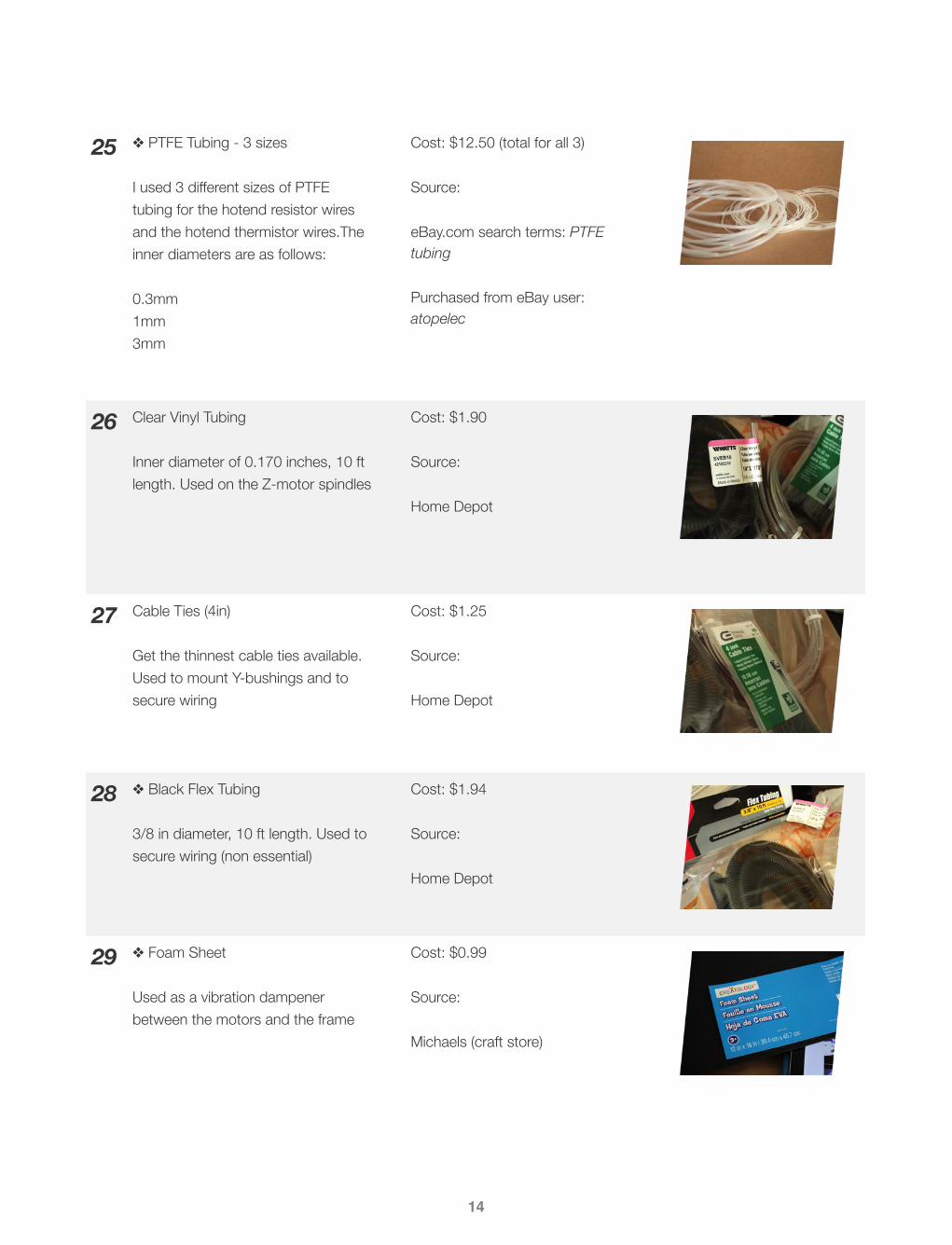
25 ❖ PTFE Tubing - 3 sizes
I used 3 different sizes of PTFE tubing for the hotend resistor wires and the hotend thermistor wires.The inner diameters are as follows:
0.3mm1mm3mm
Cost: $12.50 (total for all 3)
Source:
eBay.com search terms: PTFE tubing
Purchased from eBay user: atopelec
26 Clear Vinyl Tubing
Inner diameter of 0.170 inches, 10 ft length. Used on the Z-motor spindles
Cost: $1.90
Source:
Home Depot
27 Cable Ties (4in)
Get the thinnest cable ties available. Used to mount Y-bushings and to secure wiring
Cost: $1.25
Source:
Home Depot
28 ❖ Black Flex Tubing
3/8 in diameter, 10 ft length. Used to secure wiring (non essential)
Cost: $1.94
Source:
Home Depot
29 ❖ Foam Sheet
Used as a vibration dampener between the motors and the frame
Cost: $0.99
Source:
Michaels (craft store)
14
15
1 Arduino MEGA 2560 R3
There are multiple Arduino Mega clones available, but as this is the most critical electronics component of the entire printer I would recommend getting a trusted name brand microcontroller
Cost: $20.90
Source:
eBay.com search terms: arduino mega 2560 r3
Purchased from eBay user: electronicworld2012
2 RAMPS 1.4 Board
I purchased a preassembled RAMPS board, but kits are available, as well as just the RAMPS PCB if you wanted to source all of the components yourself
Cost: $24.78
Source:
eBay.com search terms: ramps 1.4 reprap controller
Purchased from eBay user: womarts
3 A4988 StepStick Kit - x4 pcs
For the stepper drivers, I purchased the StepStick brand kit. The agreed upon top-tier stepper drivers are the Pololu brand drivers, so I took a chance with the less expensive StepSticks. Luckily, they work perfectly, and have the same features as the Pololu kit
Cost: $43.10
Source:
eBay.com search terms: aa4988 stepstick stepper driver reprap
Purchased from eBay user: eetechnology
4 12V DC 30A 360W PSU
This power supply is a common choice for most RepRap applications. It easily runs the PCB Heatbed, the hotend, and a variety of fans
Cost: $27.88
Source:
eBay.com search terms: regulated psu 12v 30a 360w
Purchsed from eBay user: dazzlewerllc
1.3 · Electronics - Total Cost: $286.71

5 US 3-Prong Power Cable
Standard 3-prong power cable. Be careful with where you purchase from, as I purchased a $2 cable which would intermittently lose power
Cost: $5.00
Source:
eBay.com search terms: us 3 prong power cable
Purchased from eBay user: scooter0011
6 J-Head Hotend Nozzle
I can only recommend that you purchase a genuine J-Head nozzle. There are a ton of Chinese made J-Head clones that sell for cheap, but I have read about multiple instances of those heads clogging and being a waste of money, so be careful
Cost: $68.29
Source:
reprap-usa.com
7 NEMA 17 Stepper Motors - x5 pcs
Pay special attention to the item number to the right, as it denotes the NEMA 17 motor with the proper torque specs for a RepRap printer
Cost: $64.94 ($12.99 ea)
Source:
automationtechnologiesinc.comItem# KL17H247-168-4A
8 Mechanical Endstops - x3 pcs
These endstops came already mounted on printed endstop holders. Another option is to use optical endstops. No definitive answer is available as to which is better, as they both work nearly identical
Cost: $7.69
Source:
eBay.com search terms: endstop mechanical reprap 3d printer
Purchased from eBay user: norcal-reprap
9 ❖ MK2A PCB Heatbed
This heatbed seems so be the most widely available and popular unit, and I have experienced great results with it
Cost: $14.54
Source:
eBay.com search terms: mk2a heatbed pcb reprap 3d printer
Purchased from eBay user: womarts
16

17
10 ❖ 30mm Mini 12V DC Fan - x2 pcs
These are small fans that I used for the Extruder hotend as well as the RAMPS 1.4 board
Cost: $4.86
Source:
eBay.com search terms: mini fan 30mm 12v dc
Purchased from eBay user: tinxi-clothes
11 ❖ 4 Position Terminal Block
Used to connect the Z-motor wires
Cost: $3.14
Source:
eBay.com search terms: 4 position terminal block strip
Purchased from eBay user: ninos1
12 ❖ 3-Prong Power Panel Socket
Used so that the power cable to the PSU is easily removable. I eventually plan to print a PSU front face cover to mount the power socket as well as a main power switch
Cost: $1.59
Source:
eBay.com search terms: 3 prong power panel socket cable
Purchased from eBay user: digi-accessary

18
1.4 · Cost Analysis
Given the previous parts acquisition list, the printer total cost is as follows:
Note that if we exclude the non essential parts, we get the following total:
Keep in mind that PLA filament has a lower melting temperature than ABS filament. As a result, if you plan to only print PLA, you do not need to use a PCB Heatbed, as the PLA sticks to the bed at room temperature. This helps keep the cost down, as reflected in the price differences above.
Of course, the total cost will vary by location and availability of components. Also, you can assume there will be extra mis-cellaneous costs along the way, but it can be safe to say that you can build your Prusa i2 FDM for around $500. At this price point, you will be unable to find a printer capable of the same print quality with the same build volume, period.
Printed Parts $48.40
Hardware $153.62
Electronics $286.71
TOTAL $488.73
Printed Parts $48.40
Hardware $129.05
Electronics $262.58
TOTAL $440.03

BUILD INSTRUCTIONS2The following build instructions are a simplified and picture-heavy guide. There is significant documentation from a variety of sources, most notably the outstanding Prusa Mendel Visual Instructions created by Gary Hodgson, located at the follow-ing link: http://garyhodgson.com/reprap/prusa-mendel-visual-instructions/.
For more information regarding the build process, refer again to the Prusa Mendel RepRap wiki page (more specifically, under “How to Build Prusa Mendel: http://reprap.org/wiki/Prusa_Mendel_Build_Manual.)
Take note that the final build volume of the Prusa Mendel as outlined in this guide will be approximately as follows:• X axis: 200 mm• Y axis: 200 mm• Z axis: 100 mm
Take note, the Prusa Mendel has a frame that is completely scalable. For example, the threaded shafts used for the vari-ous frame elements could theoretically be doubled in length, potentially giving a print size of 400 mm x 400 mm x 200 mm. While this may not provide the most structurally sound frame, it gives the builder an idea of the possibilities of the rela-tively modular Prusa design.
19

20
2.1 · Frame Triangles
Two frame triangles make up the main structural component of the Prusa Men-del frame. The plastic parts used for the triangles are the Bar Clamp, Frame Ver-tex, and the Frame Vertex with Foot. The finished assembly should look like Fig. 2.1 to the right.
To start, thread an M8 nut onto one of six 370mm M8 threaded rods near the center. Slide on an M8 washer, followed by a Bar Clamp, followed by another washer. Thread another nut onto the other side. The finished bar should look like Fig. 2.2 to the left.
Note: do not tighten the nuts yet.
Next, using the rod assembled in the previous step, thread a nut onto one end of the rod, fol-lowed by a washer. Slide this end through the Frame Vertex with Foot, as shown in Fig. 2.3 to the right. Make sure it passes through the hole clos-est to the foot, with the upper round edge facing outward. Place a washer onto the rod, then thread a nut onto the end. Repeat on the other end of the rod.
Fig. 2.3
Fig. 2.2
Fig. 2.1

Using a second 370mm M8 threaded rod, thread an M8 nut onto one side, followed by an M8 washer. Slide that side of the rod into the Frame Vertex with Foot, making sure it passes through the hole closest to the upper round edge of the component. Add a washer to the end of the rod, followed by a nut, as pictured in Fig. 2.4. Using a third 370mm M8 threaded rod, repeat the previous steps with the other Frame Vertex with Foot.
To complete the frame triangle, thread a nut and washer onto the two remaining bare ends of threaded rod. Now, slide the rods into the Frame Vertex. Finally, place two more washers, and then thread two more nuts on the rod ends as shown in Fig. 2.5 to the left. Repeat all the previous steps to complete the second frame triangle (they should be identical).
Fig. 2.4
Fig. 2.5
21

22
To complete the rear threaded rods, start with two of the four 294mm M8 threaded rods, two Bar Clamps, one 608ZZ bearing, and one Bearing Guide set, all as shown in Fig. 2.6 to the right. Fig. 2.7 below (source: reprap.org) shows a clear view of the order in which the parts are added onto the rods. All nuts are M8, and all washers are M8.
Note: If preferred, you can use two fender wash-
ers to create a bearing guide instead of using the
printed part.
The two rear threaded rods should now look as shown in Fig. 2.8 to the left. If using the printed Bearing Guide set, make sure two M8 washers are placed on each side in between the M8 nuts and the 608ZZ bearing. If us-ing fender washers instead, make sure the M8 washers are placed in between the large washer and the 608ZZ bear-ing.
2.2 · Rear Threaded Rods
Fig. 2.6
Fig. 2.7
Fig. 2.8
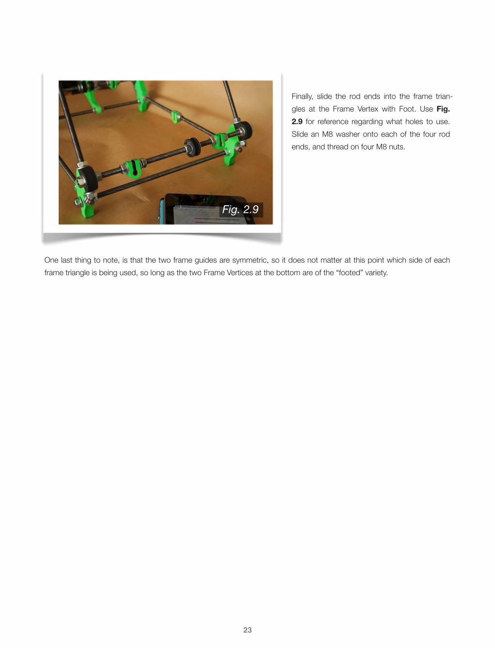
Finally, slide the rod ends into the frame trian-gles at the Frame Vertex with Foot. Use Fig. 2.9 for reference regarding what holes to use. Slide an M8 washer onto each of the four rod ends, and thread on four M8 nuts.
One last thing to note, is that the two frame guides are symmetric, so it does not matter at this point which side of each frame triangle is being used, so long as the two Frame Vertices at the bottom are of the “footed” variety.
23
Fig. 2.9

24
2.3 · Front Threaded Rods
To complete the front threaded rods, start with two of the four 294mm M8 threaded rods. The front threaded rods, as seen in Fig. 2.10 to the right, are most easily assembled working from the center outward in both di-rections. Fig. 2.11 below (source: reprap.org) shows a clear view of the order in which the parts are added onto the rods. All nuts are M8, and all washers are 8mm. You will also use two Bar Clamps, the Y-Motor Bracket, one 608ZZ bearing, and one Bearing Guide set.
Once the two front threaded rods look as they do above, add the Y-Motor Bracket to the position shown in Fig. 2.12 to the left. Take care to note the position of the bearing guide in respect to the Y-Motor Bracket, as the placement is important.
Fig. 2.10
Fig. 2.12
Fig. 2.11
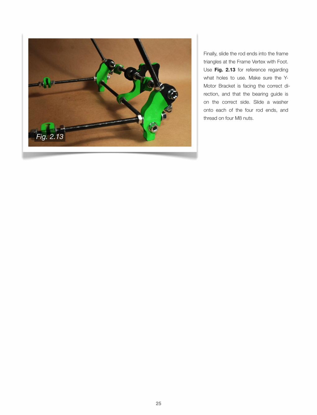
Finally, slide the rod ends into the frame triangles at the Frame Vertex with Foot. Use Fig. 2.13 for reference regarding what holes to use. Make sure the Y-Motor Bracket is facing the correct di-rection, and that the bearing guide is on the correct side. Slide a washer onto each of the four rod ends, and thread on four M8 nuts.
25
Fig. 2.13

26
2.4 · Top Threaded Rods
To complete the top threaded rods, you will need two 440mm M8 threaded rods, along with the two Z-Motor Mounts, as shown in Fig. 2.14 to the right. Slide the two rods through one of the top Frame Vertices. Make sure you do not slide the rods through the other Frame Vertex quite yet. Slide on one M8 washer onto each rod, followed by two M8 nuts for each rod, followed by one more washer on each rod. The assembly should look like Fig. 2.15 below at this point.
You can now slide both rods through the other Frame Vertex as shown below in Fig. 2.16. Adjust the rod so that it is cen-tered between the two top Frame Vertices. Readjust the nuts so that they are tight against the inside of the Frame Vertices.
Fig. 2.15
Fig. 2.14
Fig. 2.16

See Fig. 2.17 below as a reference for where each M8 nut and washer will be placed. Make sure both rods are centered on the frame so that there is an even amount of space for each of the outside nuts.
Once the rods are centered, and the inside nuts are tightened, slide an M8 washer onto each rod, fol-lowed by an M8 nut, as shown in Fig. 2.18 to the left. Repeat this step for the other side as well.
Next, add another washer to each rod, then slide on the Z-Motor Mount as shown in Fig. 2.19 to the right. To finish, slide a washer onto each rod end, then add an M8 nut to each end.
27
Fig. 2.17
Fig. 2.18
Fig. 2.19

28
2.5 · Frame Tightening
At this stage the frame can now be tight-ened. To start, take the 440mm M8 threaded rod, and slide it through the two Bar Clamps attached to the bottom rod of the frame triangles as shown in Fig. 20 to the right. Make sure that the threaded rod is centered between the two frame trian-gles as shown below in Fig. 2.21 (source: reprap.org). Using the 234mm measuring rod, use it to tighten the bottom rod of the frame triangles.
Using the same 234mm measuring rod, tighten the front threaded rods and rear threaded rods as shown in Fig. 2.22 to the left. The base of the frame should be a perfect square, with the corners being right to each other. It may be helpful to use a square to en-sure the correct tightening of the base.
Fig. 2.20
Fig. 2.21
Fig. 2.22

Using the 234mm measuring rod, tighten the top threaded rods as shown in Fig. 2.23 to the right. Readjust and tighten the Z-Motor Mounts as neces-sary to ensure that the threaded rods are still centered on the frame triangles. Once the top threaded rods are tight-ened, the upper rods of the frame trian-gles can now be tightened.
Using the 290mm measuring rod, tighten the upper rods of the two frame triangles as shown in Fig. 2.24 to the left. Make sure that the entire frame, front, rear, and top threaded rods are all square, straight, and level. Don’t hesitate to take your time on this section, as it will help immensely with the final quality of your prints.
To finish, refer back to Fig. 2.21. You will thread an M8 nut onto each end of the 440mm threaded rod. Slide an M8 washer onto each end, then slide on a Bar Clamp onto each end. Finish it with a washer, and lastly a nut. The final assembly should look like Fig. 2.25 to the right.
29
Fig. 2.24
Fig. 2.23
Fig. 2.25

30
2.6 · X-Axis
To begin the assembly, start with the two 405mm 8mm smooth rods. Position the X-End Idler and X-End Motor Mount as shown in Fig. 2.26 to the right, making sure that the hexago-nal shape of each is facing toward the center of the smooth rods.
Slide both smooth rods into the X-End Idler as shown in Fig. 2.27 to the left.
Next, slide 2 LM8UU linear bearings onto each smooth rod, as shown in Fig. 2.28 to the right.
Slide the X-End Motor Mount onto the other end of the smooth rods, as shown in Fig. 2.29 to the left.
Fig. 2.26
Fig. 2.27
Fig. 2.28
Fig. 2.29

The X-End Idler holds the X-belt bearing guide. To assemble, choose a scrap piece of 8mm threaded rod, or use a 25-50mm long M8 set screw. You will also need three or four M8 washers, two M8 nuts, one 608ZZ bearing, and one printed Bearing Guide set, as shown in Fig. 2.30 to the right.
Feed the rod through the hole in the X-End Idler, and on the inside end slide on an M8 washer followed by an M8 nut. On the opposite, forward facing side, slide on a washer (or two, depending on the placement of the X-belt), followed by a 608ZZ bearing and Bearing Guide set. Then, slide on another washer, and finally thread on an M8 nut as seen in Fig. 2.31 to the left.
To complete the X-axis assembly, insert a 15mm M3 bolt into the two holes in both the X-End Idler and X-End Motor Mount as shown in Fig. 2.32 below. Slide an M3 washer onto each end of the bolt ends, and thread an M3 nut onto each bolt end, again as shown in Fig. 2.33 below. Do not completely tighten the nuts yet, as the smooth rods may have to be adjusted in a later step.
Fig. 2.30
Fig. 2.31
Fig. 2.32 Fig. 2.33
31

32
2.7 · Y-Axis
For the Y-axis assembly, you will use the two 420mm 8mm smooth rods. Slide one rod through a Bar Clamp on either the front or rear threaded rod assembly. Then, slide on two LM8UU linear bearings onto the rod. Slide it into the opposite end of the frame, through the Bar Clamp as shown in Fig. 2.34 to the right. Re-peat this step for the other Bar Clamps, again sliding two LM8UU linear bearings onto the smooth rod.
As shown in Fig. 2.35 to the left, snap the Y-Bushings onto the LM8UU linear bearings. Use the 4 inch cable ties to secure the Y-Bushings to the linear bearings.
At this point, the smooth rods of the Y-axis can now be tight-ened. As shown in Fig. 2.36 to the right, distances M1 and M2 should be equal. Generally, it is recommended that the smooth rods be centered on the build frame. As such, M1 and M2 should be approxi-mately equal to around 40mm. Once the first rod (top rod in the figure) is set in place, tighten the second smooth rod at a distance of 140mm from the first. Keep in mind these dis-tances are simply guidelines, and can be altered to fit the spe-cific needs of your build.
Fig. 2.34
Fig. 2.35
Fig. 2.36
33
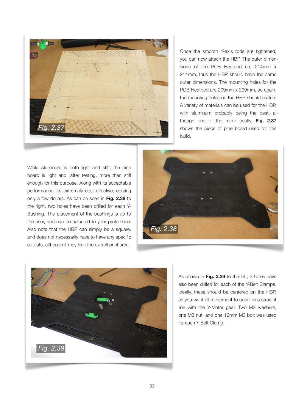
Once the smooth Y-axis rods are tightened, you can now attach the HBP. The outer dimen-sions of the PCB Heatbed are 214mm x 214mm, thus the HBP should have the same outer dimensions. The mounting holes for the PCB Heatbed are 209mm x 209mm, so again, the mounting holes on the HBP should match. A variety of materials can be used for the HBP, with aluminum probably being the best, al-though one of the more costly. Fig. 2.37 shows the piece of pine board used for this build.
While Aluminum is both light and stiff, the pine board is light and, after testing, more than stiff enough for this purpose. Along with its acceptable performance, its extremely cost effective, costing only a few dollars. As can be seen in Fig. 2.38 to the right, two holes have been drilled for each Y-Bushing. The placement of the bushings is up to the user, and can be adjusted to your preference. Also note that the HBP can simply be a square, and does not necessarily have to have any specific cutouts, although it may limit the overall print area.
As shown in Fig. 2.39 to the left, 2 holes have also been drilled for each of the Y-Belt Clamps. Ideally, these should be centered on the HBP, as you want all movement to occur in a straight line with the Y-Motor gear. Two M3 washers, one M3 nut, and one 12mm M3 bolt was used for each Y-Belt Clamp.
Fig. 2.37
Fig. 2.38
Fig. 2.39
Next, mount the HBP onto the four Y-Bushings, as shown in Fig. 2.40 and Fig. 2.41 above. You will use two 15mm M3 bolts, four M3 washers, and two M3 nuts for each Y-Bushing. Once the HBP is mounted, test to make sure it slides along the Y-axis with ease. If it binds up at any point, ad-just the M8 nuts surrounding the Bar Clamps to which the Y-axis smooth rods are mounted to. Once the printer is up and running, check again to make sure the Y-Motor has no trouble moving the HBP, as any hinderance will most certainly af-fect final print quality.
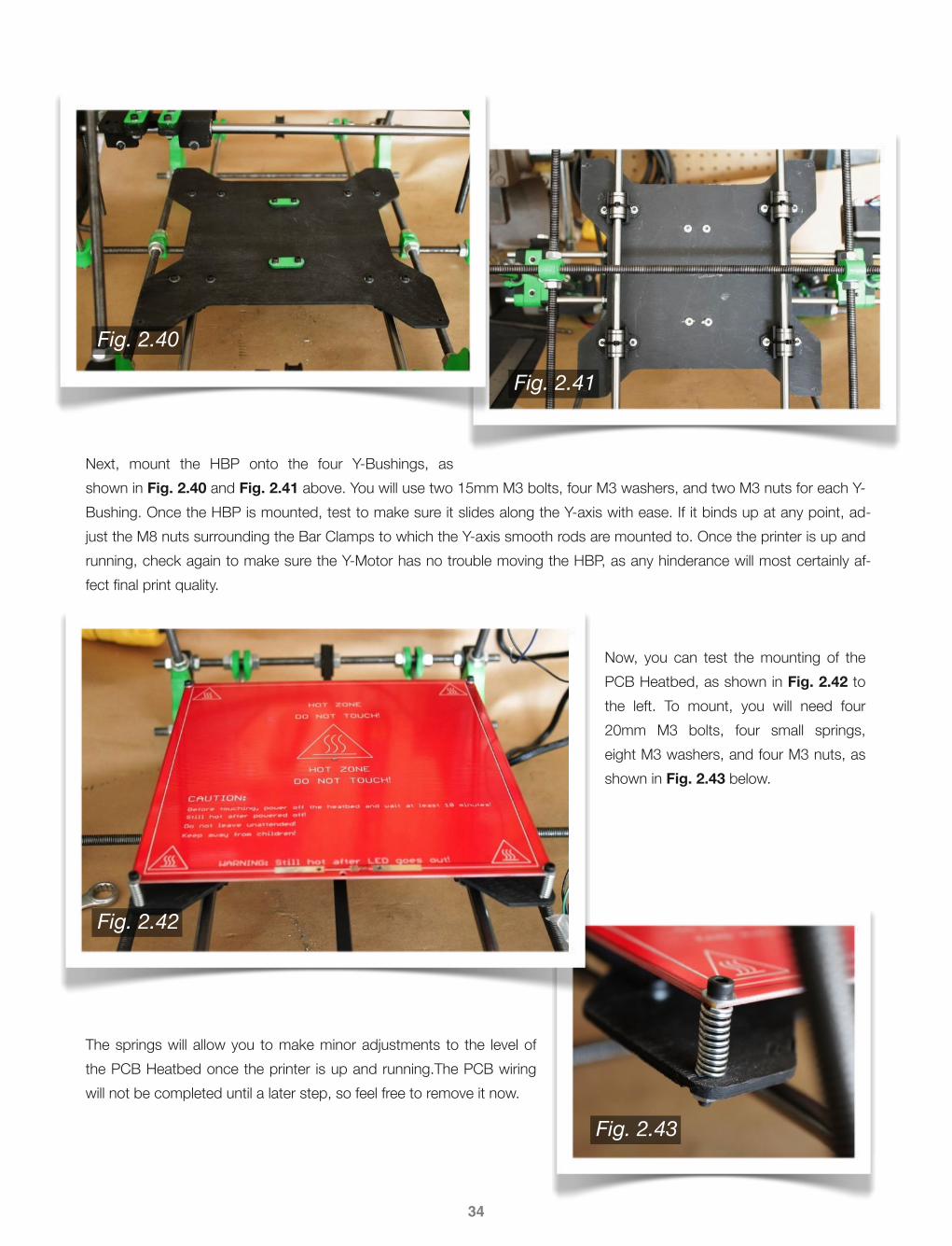
Now, you can test the mounting of the PCB Heatbed, as shown in Fig. 2.42 to the left. To mount, you will need four 20mm M3 bolts, four small springs, eight M3 washers, and four M3 nuts, as shown in Fig. 2.43 below.
The springs will allow you to make minor adjustments to the level of the PCB Heatbed once the printer is up and running.The PCB wiring will not be completed until a later step, so feel free to remove it now.
34
Fig. 2.40
Fig. 2.41
Fig. 2.42
Fig. 2.43

35
2.8 · Z-Axis
To begin the assembly of the Z-axis, you must first complete the X-axis assembly. To do so, you will first align the vertical rod clamps, located on the Z-Motor Mount and the Bar Clamp directly below it. Simply drop a weighted plum line down the first clamp slot, and adjust the bottom Bar Clamp until they are aligned, as shown in Fig. 2.44 to the left and Fig. 2.45 below.
Slide the 350mm 8mm smooth rod down through the top rod (Fig. 2.46 below), and slide two LM8UU linear bearings onto the rod. Then insert the free end into the bottom Bar Clamp, and tighten the clamp.
Next, insert the X-axis assembly from Section 2.6 by snap-ping the X-End Idler and X-End Motor Mount onto the two linear bearings on each side as shown below in Fig 2.47.
Ensure that the two smooth rods are perfectly parallel to each other. The X-axis assembly should be able to freely slide up and down, with out any binding near the top and bottom.
Fig. 2.44
Fig. 2.45
Fig. 2.46
Fig. 2.47

Using four 25mm M3 bolts and four M3 nuts, tighten the X-End Idler and X-End Motor Mount against the LM8UU linear bearings as shown in Fig. 2.48 to the left. Now, fully tighten the M3 bolts located at the bottom of the X-End Idler and X-End Motor Mount. Double check to make sure the X-axis assembly still slides freely up and down along the smooth rods.
The next step will be installing the Z-Motors. Prior to that however, is to install the optional craft foam, to aid in absorbing any motor vibrations, which will theoreti-cally help with final print quality. Again, this step is op-tional, so feel free to skip it if you choose. To start, cut out a paper template of the Z-Motor Mount base, as shown in Fig. 2.49 to the right.
Trace the template in the foam as shown in Fig. 2.50 below, then cut the final shape, noting the four slices to allow for the M3 bolt to pass through as shown in Fig. 2.51 below.
36
Fig. 2.48
Fig. 2.49
Fig. 2.50
Fig. 2.51

As shown in Fig. 2.52 to the left, place the foam into the Z-Motor Mount. Place one NEMA 17 motor into each of the Z-Motor Mounts, as shown in Fig. 2.53 below. The direction does not matter, but think ahead about how you will route the wiring for the motors. Using four 10mm M3 bolts and four M3 washers for each side, mount the motors to the Z-Motor Mounts as shown in Fig. 2.54 below. Tighten the motors so that there is no play when you try to move it by hand. Make sure the motor is seated straight and level, so that the mo-tor’s spindle travels straight and parallel to the smooth rod.
Clear vinyl tubing, as shown in Fig. 2.55 below is used for the next step. Cut two pieces approximately 22mm long (Fig. 2.56). Refer back to Section 1.2 of the Parts Acquisition list to see what size tubing is required. This tubing is not optional, as it is required to ensure smooth operation of the Z-axis.
37
Fig. 2.52
Fig. 2.53 Fig. 2.54
Fig. 2.55 Fig. 2.56
As shown in Fig. 2.57 to the left, slide the clear vinyl tubing on to the motor spindle for both side. The bottom of the clear vinyl tubing should be flush with the very end of the spindle.
To complete the Z-axis assembly, you will need two 210mm M8 threaded rods, four M8 nuts, two large springs, and two Coupler sets.
Note, there are aluminum couplers available online, which
some users have recommended, and others have claimed are
no different than the printed parts.
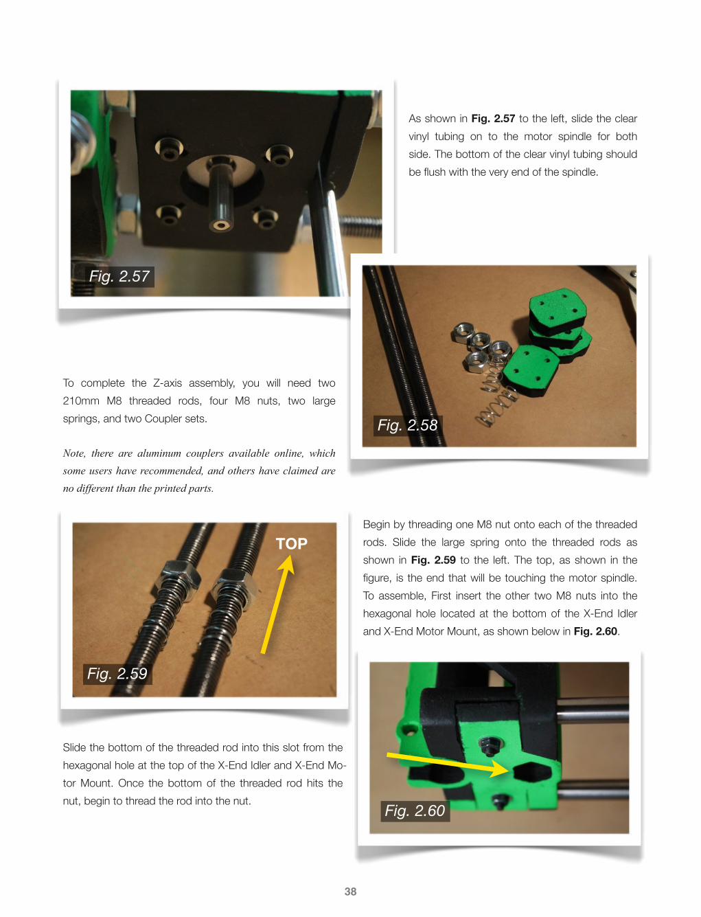
Begin by threading one M8 nut onto each of the threaded rods. Slide the large spring onto the threaded rods as shown in Fig. 2.59 to the left. The top, as shown in the figure, is the end that will be touching the motor spindle. To assemble, First insert the other two M8 nuts into the hexagonal hole located at the bottom of the X-End Idler and X-End Motor Mount, as shown below in Fig. 2.60.
Slide the bottom of the threaded rod into this slot from the hexagonal hole at the top of the X-End Idler and X-End Mo-tor Mount. Once the bottom of the threaded rod hits the nut, begin to thread the rod into the nut.
38
Fig. 2.57
Fig. 2.58
Fig. 2.59
Fig. 2.60
TOP

To clarify, the threaded rod will enter the hexagonal slot from above, as shown in Fig. 2.61 to the left. Again, the threaded rod will be threaded into the M8 nut in the bottom hexagonal hole. The large spring will be between the two M8 nuts at this point, and their purpose is to damper the change of layer movement of the X-Carriage. Continue to thread thread the rod through the nut until the top of the threaded rod sits di-rectly underneath (Note: practically touching) the motor spindle.
At this point, you should be able to clamp the Coupler onto the spindle and threaded rod as shown in Fig. 2.62 to the right. Using four 20mm M3 bolts, eight M3 washers, and four M3 nuts for each Coupler set, tighten the two clamped pieces onto the rods. Once the printer is running, check the Couplers from time to time, as they may expe-rience fatigue from heat and regular motion - an-other reason why an aluminum coupler set might be a good idea.
39
Fig. 2.61
Fig. 2.62

40
2.9 · X-Carriage & Extruder
Now that the frame is square and level, you can begin the X-Carriage assembly. To start, snap the X-Carriage onto the X-axis smooth rods as shown in Fig. 2.63 to the left. Take note to which direction the X-Carriage is facing, as it is important. If you notice the boxed sec-tion in Fig. 2.64 below, this side of the X-Carriage should also be on the same side that the motor is mounted onto the X-End Motor Mount.
Once the X-Carriage is snapped in place, tighten the LM8UU linear bearing mounts as shown in Fig. 2.65 below. You will use one 15mm M3 bolt, two M3 wash-ers, and one M3 nut for each linear bearing.
Moving on to the Extruder, start by inserting one 608ZZ bearing into the Extruder Body, as shown below in Fig. 2.66. The face of the bearing should sit flush with the surface of the Extruder Body. If it does not, clear out any extraneous plastic debris.
Fig. 2.63
Fig. 2.64
Fig. 2.65
Fig. 2.66

Insert the Hobbed Bolt into the Large Gear as shown in Fig. 2.67 to the left. Make sure the bolt is inserted com-pletely into the gear, using a hammer or similar tool if necessary. Also check to make sure that the bolt sits perpendicular to the back face of the gear, or else the gear may rotate at an unwanted angle.
Slide two M8 washers onto the Hobbed Bolt, then slide the Large Gear assembly into the Ex-truder Body as shown in Fig. 2.68 to the right.
Insert another 608ZZ bearing into the backside of the Ex-truder Body as shown in Fig. 2.69 to the left. Completely slide the Large Gear assembly into the Extruder Body. The teeth of the Hobbed Bolt should sit perfectly centered on the hole through which the filament will pass through. If the teeth are off center, you can add or remove washers to compensate.
Slide two more M8 washers onto the end of the bolt, and finish with one M8 nut and finally one M8 lock nut ash shown in Fig. 2.70 to the right. Do not tighten the nuts so much that the Large Gear does not freely ro-tate, but tighten them enough so that there is no front-to-back slop within the Large Gear assembly.
41
Fig. 2.67
Fig. 2.68
Fig. 2.69
Fig. 2.70

To assemble the Extruder Guidler, you will need one 608ZZ bearing, one M3 nut, and a 20mm length of smooth rod. Slide the 608ZZ bearing onto the smooth rod, and snap the two pieces into the Guidler as shown in Fig. 2.71 to the left. Insert the M3 nut into the space provided.
The Small Gear will be attached to the extruder motor spindle. In-sert an M3 nut into the space provided, as shown in Fig. 2.72 to the right. Screw an 8mm M3 set screw into the M3 nut. Note, the Small Gear should be “meshed” with the Large Gear prior to attach-ing the extruder motor to the Extruder Body. Another alternative is to attach the extruder motor and Small Gear to the Extruder Body first, then insert the Large Gear assembly into the Extruder Body afterwards. Either option is fine.
As shown in Fig. 2.73 to the left, the extruder mo-tor is attached to the Extruder Body using three 10mm M3 bolts. There is a foam cutout in between to help dampen motor vibrations. Insert one M3 nut into each of the holes shown by the yellow ar-rows in the figure to the left. Then screw in two 50mm M3 bolts.
As shown in Fig. 2.74 to the right, each bolt end will have a spring surrounded by two M3 washers. Note, M4 sized bolts of sufficient length can be used here if you prefer.
42
Fig. 2.71
Fig. 2.72
Fig. 2.73
Fig. 2.74

43
2.10 · Electronics
The first step in electronics installation will be to attach the re-maining motors. The Z-axis motors have already been mounted, as well as the extruder motor. Prior to installing the X-axis motor, first install one of the GT2 aluminum pulleys onto the motor spin-dle as shown in Fig. 2.75 to the left.
As with the motors before, cut out a layer of foam to help dampen the vibrations of the motor, as shown in Fig. 2.76 to the right.
Using three 10mm M3 bolts, attach the X-axis motor to the X-End Motor Mount as shown in Fig. 2.77 to the left. Again, the position of the motor is not critical, but some thought should be given to the placement of the wires.
Using four 15mm M3 bolts and four M3 washers, attach the Y-axis motor to the Y-Motor Bracket as shown in Fig. 2.78 to the right.
Fig. 2.75
Fig. 2.76
Fig. 2.77
Fig. 2.78

As before, use a foam cutout in between the Y-axis motor and the Y-Motor Bracket as shown in Fig. 2.79 to the left.
Install the second GT2 aluminum pulley onto the spindle of the Y-axis motor as shown in Fig. 2.80 to the right. Take note of the position of the GT2 aluminum pulley - it must be aligned with the Bearing Guide located on the Front Threaded Rod assembly. This most likely will re-quire the pulley to be flipped as shown to the right.
Next, install the Y-axis belt. If you purchased a one meter length of belt, cut it in half. As shown in Fig. 2.81 to the left, the belt will wrap around the Y-axis pulley as well as the front Bearing Guide. Remember that the teeth of the belt must face inward in order to engage the pulley teeth, with the smooth side of the belt facing outward.
AS shown in Fig. 2.82 to the right, clamp the belt down to the HBP using the two Y-Belt Clamps. The belt should be taut, but not too tight. A good test is to pluck the belt with your finger, and it should have a low pitched ring.
44
Fig. 2.79
Fig. 2.80
Fig. 2.81
Fig. 2.82

The X-axis belt is to be installed next, similar to the Y-axis belt. Wrap the belt around the X-axis GT2 alumi-num pulley as shown in Fig. 2.83 to the left. Again, make sure the teeth of the belt are facing inward so that they engage the pulley.
Install the X-Belt Clamps using four 15mm M3 bolts and eight M3 washers as shown in Fig. 2.84 to the right. You can use the available slot in the X-Carriage to feed the belt excess so it does not hang down, as shown to the right.
To assemble the J-Head hotend, insert the resistor and thermis-tor as shown in Fig. 2.85 (source: reprap-usa.com) to the left. You can use kapton tape or high-temp aluminum foil tape to keep the thermistor in place. Slide 0.3mm inner diameter PTFE tubing onto the leads of the thermistor, and slide 1mm inner diamter PTFE tubing onto the leads of the resistor.
Using the optional aluminum hotend mount plate, mount the J-Head onto the X-Carriage using two 20mm M4 bolts as shown in Fig. 2.86 to the right. If using an Extruder Body made out of PLA, an alumi-num mount plate is a good idea, as PLA has a melt-ing point of around 160℃ which can be problematic when printing ABS at an extrusion temperature of 240℃. If the Extruder Body is made out of ABS, an aluminum mount plate is not necessary, as the J-Head can be mounted directly to the Extruder Body.
45
Fig. 2.83
Fig. 2.84
Fig. 2.86
Fig. 2.85

Three mechanical endstops will be used to establish the “home” position of the print nozzle. The X-endstop will be attached to one of the X-axis smooth rods near the X-End Idler as shown in Fig. 2.87 to the left. The metal arm should be facing inwards toward the X-Carriage. Use one 15mm M3 bolt, two M3 washers, and one M3 nut for each endstop. This location will be the X = 0 posi-tion, and movement to the right (when facing the front of the printer) will be in the positive X-direction.
The Y-axis endstop will be installed on one of the Y-axis smooth rods near the rear of the printer as shown in Fig. 2.88 to the right. Again, the metal arm should face inward toward the HBP. To ex-tend the print area, you could cut a longer smooth rod, so that the endstop can be mounted outside the frame base “sqaure”, theoretically giving you the full 200mm in the Y-direction. This location will be the Y = 0 position, with movement toward the front (as you face the front of the printer) being in the positive Y-direction.
The Z-axis endstop will be attached to the Z-axis smooth rod (either side is acceptable) as shown in Fig. 2.89 to the left. Position the endstop so that the metal arm is facing upward toward the bottom face of the X-End Idler or X-End Motor Mount (the side on which the endstop is placed is not critical). See the improvements section of Chapter 4 for a simple adjustable Z flag.
46
Fig. 2.87
Fig. 2.88
Fig. 2.89

An optional 4x2 terminal block can be used to combine the Z-axis motors as shown in Fig. 2.90 to the left. Combine the similar color wires from the two motors, as you want them both to rotate in the same direc-tion. If they turn in the opposite direction in-tended, or if one turns the wrong direction, the terminal block makes corrections very easy.
Next, you will wire the PCB Heatbed. As shown in Fig. 2.91 to the right, two LED’s and one 1/2W 1K ohm resistor will be sol-dered on the underside of the PCB Heat-bed. If possible, use surface mount elec-tronics, as they will look much cleaner. These components were easily available from a local RadioShack and work fine however.
Now, you can begin to connect the wiring of the entire printer. As shown in Fig. 2.92 to the left, the two 18 AWG wires will be fed through the available holes and soldered to the top side of the PCB Heatbed.
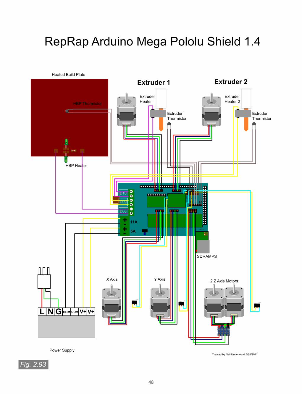
For a complete visual guide to the wir-ing setup using RAMPS 1.4, see Fig. 2.93 on the following page.
47
Fig. 2.90
Fig. 2.91
Fig. 2.92
48
D10
D09
D08
L N G COM V+COM V+
+-+-+-
-+
T1
2 Z Axis Motors
Heated Build Plate
Power Supply
X Axis Y Axis
HBP Thermistor
HBP Heater
x m
in
z m
in
RepRap Arduino Mega Pololu Shield 1.4
Created by Neil Underwood 5/28/2011
T2
-+
Extruder Heater 2
ExtruderThermistor
Extruder 1
Extruder Heater
ExtruderThermistor
Extruder 2
5A
11A
T0
y m
in
AUX-3
SDRAMPS
Fig. 2.93

Note on the previous page, two extruders can be used with the RAMPS 1.4 setup. If you choose to not use a second ex-truder, you can use a fan in place of the second extruder’s thermistor. The following wire gauges will be used for various components of the printer:
• X, Y, and Z Endstops: 24-26 AWG• HBP and Extruder Thermistor(s): 24-26 AWG• X, Y, Z, and Extruder Motors: 22 AWG• Extruder Heater (D09 and D10): 18 AWG• HBP Heater (D08): 18 AWG• Power Supply (V+ and V-): 18 AWG• Power Cable Extension Wires (Optional): 18 AWG
A small printed circuit board was used on the X-Carriage as shown in Fig. 2.94 to the left. This allowed the Extruder to be easily removable if necessary for maintenance or design changes/upgrades.
Similar to above, A small printed circuit board was used near the rear of the printer frame as shown in-Fig. 2.95 to the right. 0.1 in connection headers were used on the PCB to connect all the printer wires. This approach was taken so that a removable wiring harness could be used to help make the printer more portable. This approach does not have to be used, and I was not entirely convinced that it was any more useful than the RAMPS 1.4 shield be-ing directly mounted to the frame.
49
Fig. 2.94
Fig. 2.95

The RAMPS 1.4 shield is pictured in Fig. 2.96. The wiring harness was secured in ribbed black plastic tubing. Then, the harness was connected to the RAMPS shield using 2 or 4 position housings. Un-der most conditions, a fan is required to keep the RAMPS board components cool. Primarily, if the stepper driver motors get too hot, they will shut off to prevent damage, which means your print layer in that direction will now be off, and your print is ru-ined. See the Design Improvements section for a simple printed RAMPS base with fan mount.
As shown in Fig. 2.97 to the right, a male power cable connector was used so that the power cable can be removed easily. A printed face to mount the male connector is planned for future use, and may examples already exist on Thingiverse.com.
Lastly, affix the glass plate to the top of the PCB Heatbed using four small dogclips. If printing PLA, cover the surface of the glass with Blue Painters Tape, as PLA adheres very well to this material when not heated. If you are printing ABS, you can use a variety of solutions, but one I am fond of is vehicle window tint. ABS adheres very well to this, as the tint is a PET based material.
Fig. 2.96
Fig. 2.97
50

SOFTWARE3There are three main components of software required to run your 3-D printer. They are as follows:
• Firmware• Host Software• G-Code Generation Software
There are multiple versions of each of these components, of which most are open source. If you wish, you may try them all to determine which best suits your needs. I find that each piece of software has its own tradeoffs, so determine what features are most important to you.
As well as the components listed above, you will also need files to print. These can be found at multiple locations online, or you can create these files yourself, which will also be discussed in this chapter.
As a side note, I am using OSX. All the software I will list is compatible with OSX and Windows systems. Keep in mind that when on a Windows machine the layout of the software may be different.
For more information, see the RepRap Options page on the RepRap Wiki site: http://reprap.org/wiki/RepRap_Options.
51

52
3.1 · Firmware
The four most popular firmware options that are also compatible with RAMPS 1.4 are:
• Sprinter• Marlin• Repetier• Teacup
Download/InstallationI chose to use Sprinter, and have had very good, reliable results. I have heard of many improvements made to Marlin, and based on samples and tests I have seen it appears to provide some of the best prints.
With a RAMPS shield, I assume you will be using the Arduino MEGA 2560 R3 board. You will be installing the Sprinter fir-ware into this board. To do so, you must first download and install the Arduino Software, located on the software page of
the Arduino website:http://arduino.cc/en/main/software
The current version is listed as Arduino 1.0.5. Click the installer for your OS, and follow the install instructions. Next, you will need to download your choice of firmware.
To download Sprinter, you must visit author Kilment’s Sprinter download page on GitHub:
https://github.com/kliment/Sprinter
As shown in the following image, you can download the entire Sprinter folder simply by clicking the Download ZIP button.
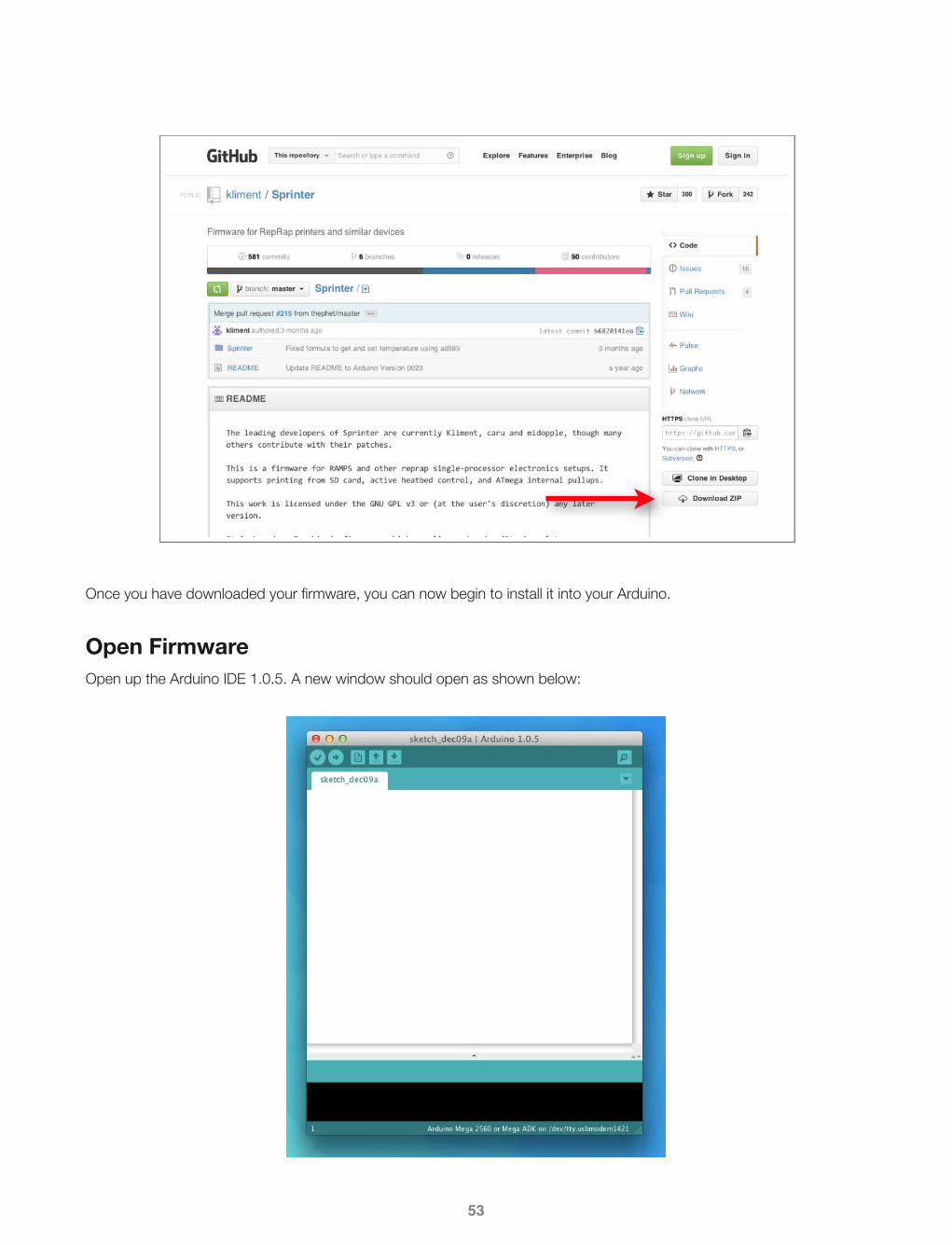
Once you have downloaded your firmware, you can now begin to install it into your Arduino.
Open FirmwareOpen up the Arduino IDE 1.0.5. A new window should open as shown below:
53

You will open a new file:
Then you will locate the Sprinter.pde file, located wherever you chose to save the Sprinter folder downloaded from GitHub.
A new Arduino window will you open, with the contents of the Sprinter folder. You can now close the first default window that opened.
54
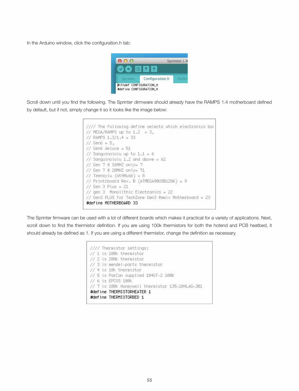
In the Arduino window, click the configuration.h tab:
Scroll down until you find the following. The Sprinter dirmware should already have the RAMPS 1.4 motherboard defined by default, but if not, simply change it so it looks like the image below:
The Sprinter firmware can be used with a lot of different boards which makes it practical for a variety of applications. Next, scroll down to find the thermistor definition. If you are using 100k thermistors for both the hotend and PCB heatbed, it should already be defined as 1. If you are using a different thermistor, change the definition as necessary.
55

Next, check your calibration variables:
It should already be set up for a Metric Prusa Mendel. As shown above, the numbers represented by {80, 80, 3200/1.25, 700} are the number of motor steps (micro rotations) required to move 1mm in each direction (or in the case of the extruder, the number of steps required to extrude 1mm of plastic). The equations used to determine these val-ues are as follows:
• #define_x_Steps_per_mm = Steps ⋅ Microstepping−1
BeltPitch ⋅ PulleyTeeth
• #define_y_Steps_per_mm = Steps ⋅ Microstepping−1
BeltPitch ⋅ PulleyTeeth
• #define_z_Steps_per_mm = Steps ⋅ Microstepping−1
Zd
• #define_e_Steps_per_mm = Steps ⋅ Microstepping−1 ⋅ ERat ioπ ⋅ BoltDiameter
Where the variables are listed as follows:
• Steps = number of motor steps per revolution (200 for 1.8 degree motor)• Microstepping = Microstepping ratio of controller (i.e. stepper motor drivers - 1/16th for StepStick drivers)• BeltPitch = distance between teeth of belt (2mm for 2M belts)• PulleyTeeth = number of teeth on pulley (20 for GT2 pulleys)• Zd = distance between threads of Z-axis rods (1.25 for M8 rods)• ERatio = gear ratio of extruder gears (39/11 for Wade’s Extruder)• BoltDiameter = Diameter of hobbed bolt, measuered at hobbed section (should be ~8mm)
The numbers provided by default by Sprinter should be good enough to get you started.To calibrate the amount of fila-ment fed through the extruder, you can extrude a known amount using your host software, then verify in your firmware that the value is correct. See the calibration section ahead for more information.
56

Again, scroll to the next section under the configuration.h tab:
You will be able to check the direction your motors are turning once your host software is setup. If one of the motors turns in the wrong direction, you can change the definition for that motor to = true; Also, take note of the BAUDRATE listed just below the Endstop Settings, as the host software will ask for that number.
Upload FirmwareNow that the Sprinter firmware is ready to go, you are ready to upload it to the Arduino MEGA 2560 R3. First, mount the RAMPS 1.4 shield onto the Arduino MEGA board if you have not done so already. Your board should look like Fig. 3.1 be-low. Plug a USB cable into the Type B slot on the Arduino as pointed out below, and plug the Type A end into your com-puter.
57
Fig. 3.1

Next, you will select the “Upload” button in the Arduino IDE window (as shown below), while at the same time pushing the side button on the RAMPS 1.4 shield (Fig. 3.2 below).
As shown above, the Arduino IDE window will show that the sketch is compiling, and some lights should be flickering on the RAMPS and Arduino. Once the Arduino IDE finishes compiling, you will have successfully installed the Sprinter firm-ware onto your Arduino MEGA.
58
Fig. 3.2

59
3.2 · Host Software
There are multiple host programs available, with the most popular being as follows:
• Pronterface• RapSnapper (must be compiled for use on OSX)• ReplicatorG• Repetier Host
Download/InstallationI chose to use Pronterface, as it was created Kilment, and therefore functions well with Sprinter. It is a visual host, with a pretty good GUI. It does not have as many features as ReplicatorG for example, but it is a simple host that is easy to use well. To download Pronterface, again you will Kilment’s GitHub, this time on the Printrun page:
https://github.com/kliment/Printrun
Scrolling down toward the bottom, you will find a precompiled link for OSX:
http://koti.kapsi.fi/~kliment/printrun/
On this page you will find the latest updates to Printrun. As of this writing, the newest version is titled Printrun-Mac-05Nov2013.zip. Download this file (or the newest version), and follow the install instructions. Once Pronterface is installed, open it, and you should see the following window:

FeaturesOnce Pronterface is set up, you will need to power up your printer so that you can test the motors and the heaters. Con-nect the Power cord to the PSU, and make sure that you have the RAMPS board set up for 12V. The printer should now have power.
PortNow that Pronterface is running, we’ll go over the various functions and features of the software. First, look to the Port button, shown above. Select the USB hub that you are plugged in to on your computer. Also, make sure that this port is running at the appropriate BAUDRATE, which was listed in the Sprinter firmware within the Arduino IDE from Section 3.1.
ConnectTo the immediate right of the BUADRATE, you will find the Connect, Reset, and Load File buttons. Selecting the Connect button will connect your printer to your computer, and the Pronterface software. In the command space on the right side of the window, you will see a positive connection message.
ResetIf, when the printer is running or connected, you experience a problem, you can select Reset to reboot the printer. For example, if a motor stops functioning because the stepper driver overheats, resetting the printer will usually get it to start working again (side note, do not forget the fan on your RAMPS board!)
Load FileWhen you select the Load File button, you will be prompted to find the file you wish to print. The filetype will be of the .gcode variety. In order to obtain a .gcode file, you will have to run your model through the G-Code generation software (see Section 3.3).
SDThe SD button allows you to print from a secure digital card that is plugged in to the RAMPS board. This allows you to un-tether your computer from the printer, but you will lose additional controls unless you have a separate controller/LCD hooked up to the printer.
PrintOnce your file is loaded, and the printer is ready, you can select the Print button to begin the print.
PauseOnce the print is started, you can pause it by pressing the Pause button. Once the Pause button is selected, it will change to a Resume button. Select Resume to start the print from where it was paused.
60

MotorsThe Motors off button allows you to shit the motors off. When the motors are on, they are “engaged” and the motor spindles are therefore immovable. When they are turned off, you can rotate the motor spindles freely, and move the HBP, X-Carriage, and Z Couplers by hand. Note the motor speeds to the right of the Motors off button. By default, the X and Y axes move at 300mm/min, and the Z axis moves at 200mm/min (actual linear speed, rather than rotational).
XYZ Axis ControlsThe visual controls shown above are used to manually position the print nozzle. For the X and Y axes, each of the four quadrants represent movement in the positive or negative direction. Each layer of the circle corresponds to a distance, measured in mm (0.1mm on the inside to 100mm on the outside). For the Z axis, the same logic applies, with the inside layer corresponding to 0.1mm and the outside layer corresponding to 10mm.
Heater ControlsShown above are the controls for the Extruder Heater as well as the PCB Heatbed. A few default options are provided for PLA and ABS for each of the heaters, which, is a great starting point. Once you choose your temperature, click the Set button on the right side, and the temperature will gradually set to the defined temperature.
61
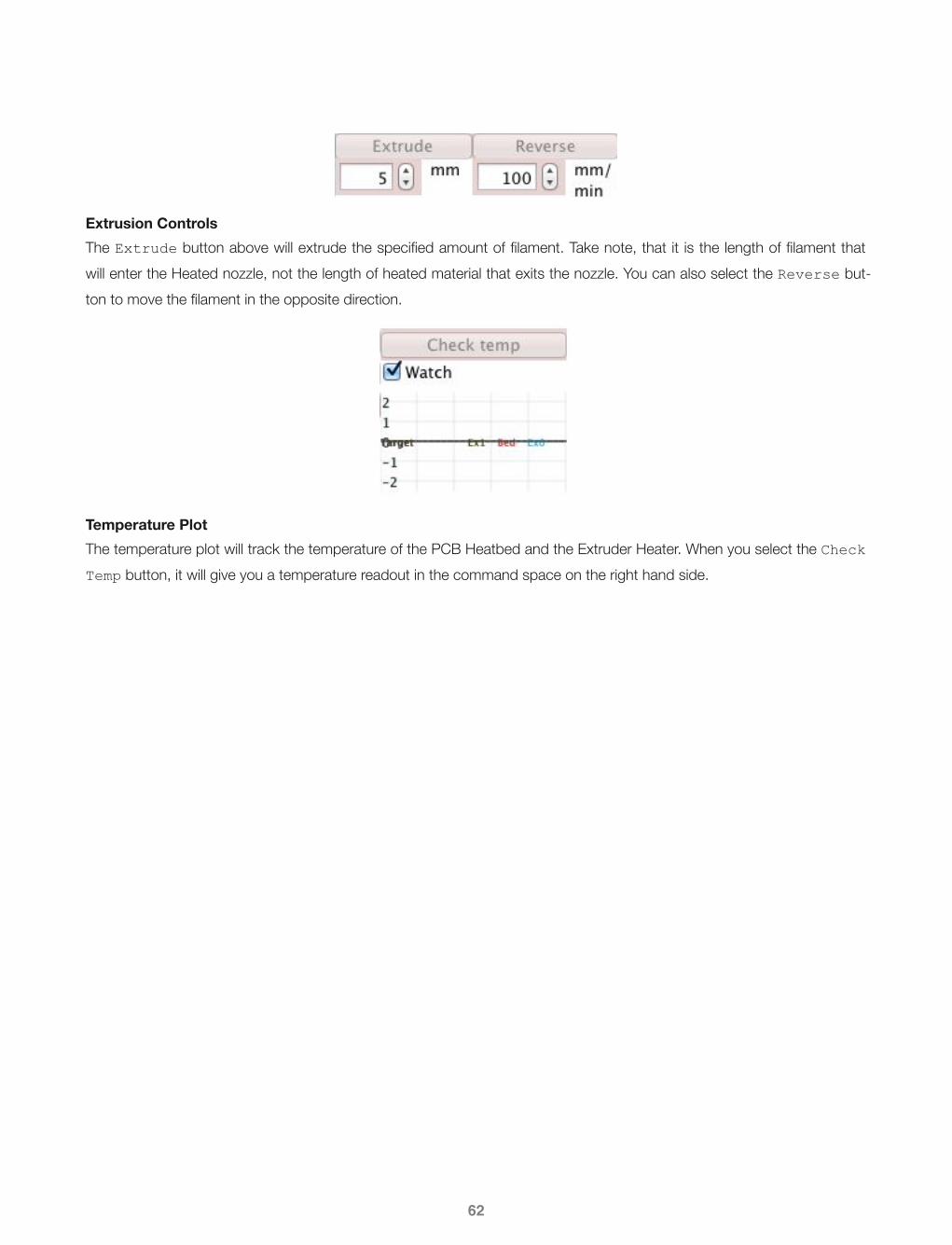
Extrusion ControlsThe Extrude button above will extrude the specified amount of filament. Take note, that it is the length of filament that will enter the Heated nozzle, not the length of heated material that exits the nozzle. You can also select the Reverse but-ton to move the filament in the opposite direction.
Temperature PlotThe temperature plot will track the temperature of the PCB Heatbed and the Extruder Heater. When you select the Check Temp button, it will give you a temperature readout in the command space on the right hand side.
62

63
3.3 · G-Code Generation Software
There are multiple G-code generators available, with the most popular being as follows:
• Slic3r• SFACT• Skeinforge
Download/InstallationI chose to use Slic3r. It is a newer G-code generator, but it has a lot of useful features, and it slices models relatively quickly compared to the others. To download Slic3r, visit the download page of the Slic3r website:
http://slic3r.org/download
Download the OSX package, and follow the install instructions. Also, be sure to check out the Slic3r user manual, located at Slic3r.org under the Manual tab.
Open Slic3rThe default window will look like the following:

PlaterAs shown in the Slic3r window, you can simply drag your file into the working grid. Make sure that your file is of the .STL filetype:
The Hollow Pyramid (by 3dprinterbot) model was downloaded from Thingiverse.com.
As shown above, you can see the model added to the model space. I chose this model because it shows clearly that the square base is established as the first print layer.
64

As shown above, the Plater tab allows you to make adjustments to your print.
MoreBy selecting the More button, you can increase the number of copies of your model that will be printed. In the example below, four identical copies of the Hollow Pyramid model will be printed.
FewerBy selecting the Fewer button, you will decrease the amount of copies printed
45º ccw/45º cw/RotateBy selecting the 45º ccw or 45º cw buttons, you will rotate the model in 45º increments in either the clockwise or counter clockwise direction. When you select the Rotate button, it will promp you to input the amount of degrees by which you wish to rotate the model (negative values will denote clockwise rotation).Scale/SplitThe Scale button will allow you to scale the model larger or smaller by entering a percentage amount. By selecting the
Split button, you will split the model up by it’s separated components (i.e. if a model is made where two or more parts do not touch, you can split them so you may make adjustments to each individual piece).
Lastly, the Export G-code button will export your model in the G-code format, which will it allow it be read by your host software, and ultimately printed by your machine.
65

Print SettingsThere are a lot of different features under the Print Settings tab, and rather than go through all of them in detail, I will pro-vide the values I use, and explain where necessary.
Layers and PerimetersLayer Height: 0.2 mmFirst Layer Height: 100%
Perimeters (minimum): 2Randomize Starting Points: YesGenerate Extra Perimeters When Needed: Yes
Solid Layers Top: 3Solid Layers Bottom: 3Avoid Crossing Perimeters: NoExternal Perimeters First: NoSpiral Vase: No
My nozzle diameter is 0.35mm, so theoretically I could have layers be as large as that. I choose to print at 0.2mm most of the time, as it gives a good balance of print resolution and speed.
InfillFill Density: 0.2Fill Pattern: RectilinearTop/Bottom Fill Pattern: Rectilinear
Infill Every: 1 LayerOnly Infill Where Needed: NoSolid Infill Every: 0 LayersFill Angle: 45ºSolid Infill Threshold Area: 70 mm2
Only Retract When Crossing Perimeters: YesInfill Before Perimeters: No
The fill density is the percentage of space inside the model that gets filled. 0.2 means 20% of the interior of the model will be filled with a rectilinear pattern. If fill density = 0, it means the part will be hollow. If fill density = 1, it means the part will be completely solid.
As far as the fill pattern goes, rectilinear is the default, and it works well. The other pattern I like is the honeycomb pattern. I don’t have any information regarding the structural integrity between these two infill patterns, so try them both out and see what you like.
66
SpeedPerimeters: 30 mm/sSmall Perimeters: 30mm/sExternal Perimeters: 70%Infill: 30 mm/sSolid Infill: 30 mm/sTop Solid Infill: 30 mm/sSupport Material: 35 mm/sBridges: 35 mm/sGap Fill: 10 mm/s
Travel: 60 mm/s
First Layer Speed: 10 mm/s
Perimeters: 0 mm/s2
Infill: 0 mm/s2
Bridge: 0 mm/s2
Default: 0 mm/s2
The speeds set above are moderate - not too fast and not too slow. You can most certainly set your layer height to 0.3mm and your print speed to 60 mm/s and achieve decent prints at a rapid rate. But for most prints of decent quality, the above should work just fine.
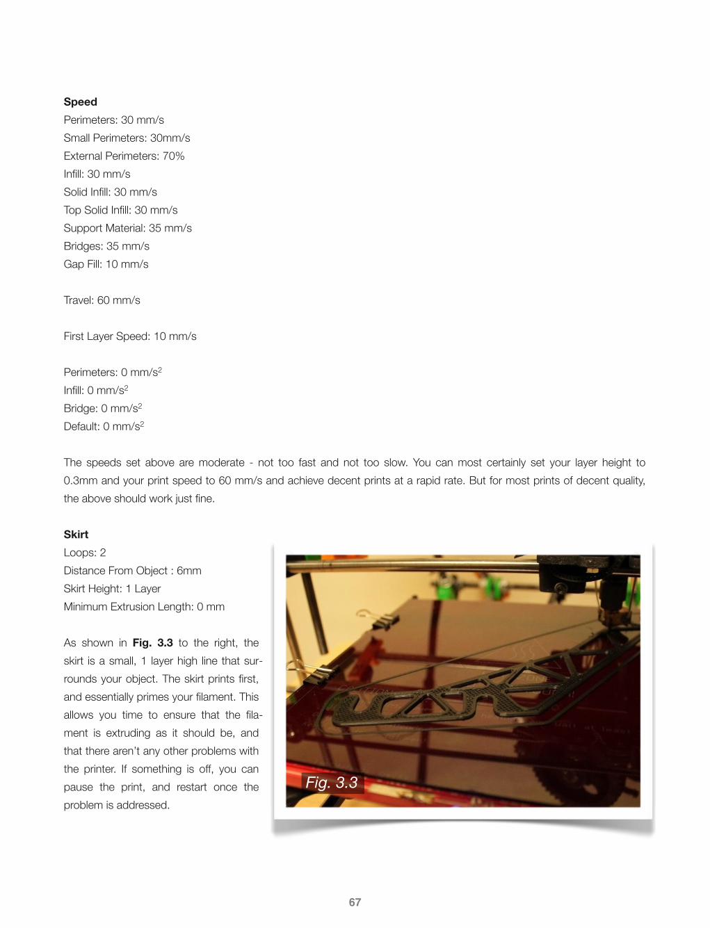
SkirtLoops: 2Distance From Object : 6mmSkirt Height: 1 LayerMinimum Extrusion Length: 0 mm
As shown in Fig. 3.3 to the right, the skirt is a small, 1 layer high line that sur-rounds your object. The skirt prints first, and essentially primes your filament. This allows you time to ensure that the fila-ment is extruding as it should be, and that there aren’t any other problems with the printer. If something is off, you can pause the print, and restart once the problem is addressed.
67
Fig. 3.3

BrimBrim Width: 0 mm
The brim is used to give you an extended surface area, which is useful if your part is having trouble sticking to the heatbed. As shown in Fig. 3.4 to the right, there is 1 layer high material that surrounds the Guidler and Ex-truder Body that are being printed. Note in the example to the right, the brim width is 5mm.
If, for example, you require a 10mm brim width, you would have to change your skirt distance from object to 10mm or greater.
Support MaterialGenerate Support Material: NoOverhang Threshold: 60ºEnforce Support For the First: 0 Layers
Raft Layers: 0 Layers
Pattern: HoneycombPattern Spacing: 1 mmPattern Angle: 0ºInterface Layers: 0 LayersInterface Pattern Spacing: 0 mm
Support material can be generated for parts that have extreme overhangs. Since this FDM printer prints layers starting at the bottom building upwards, if you have a print where a piece extends out with no material underneath, it will be very diffi-cult for that print to come out right. Support can therefore be generated by Slic3r, which is only temporary and you can remove by hand once the print is completed.
NotesN/A
Output OptionsLeave as default.
Multiple ExtrudersKeep all set to 1 as default. It is possible to have multiple extruders set up on your printer (2 extruders is a popular setup). This allows you to print multiple color plastics within the same part. There is even a water soluble PVA filament available, meaning you could use it for support structure, so once your print is done set it in water and the support will dissolve.
68
Fig. 3.4
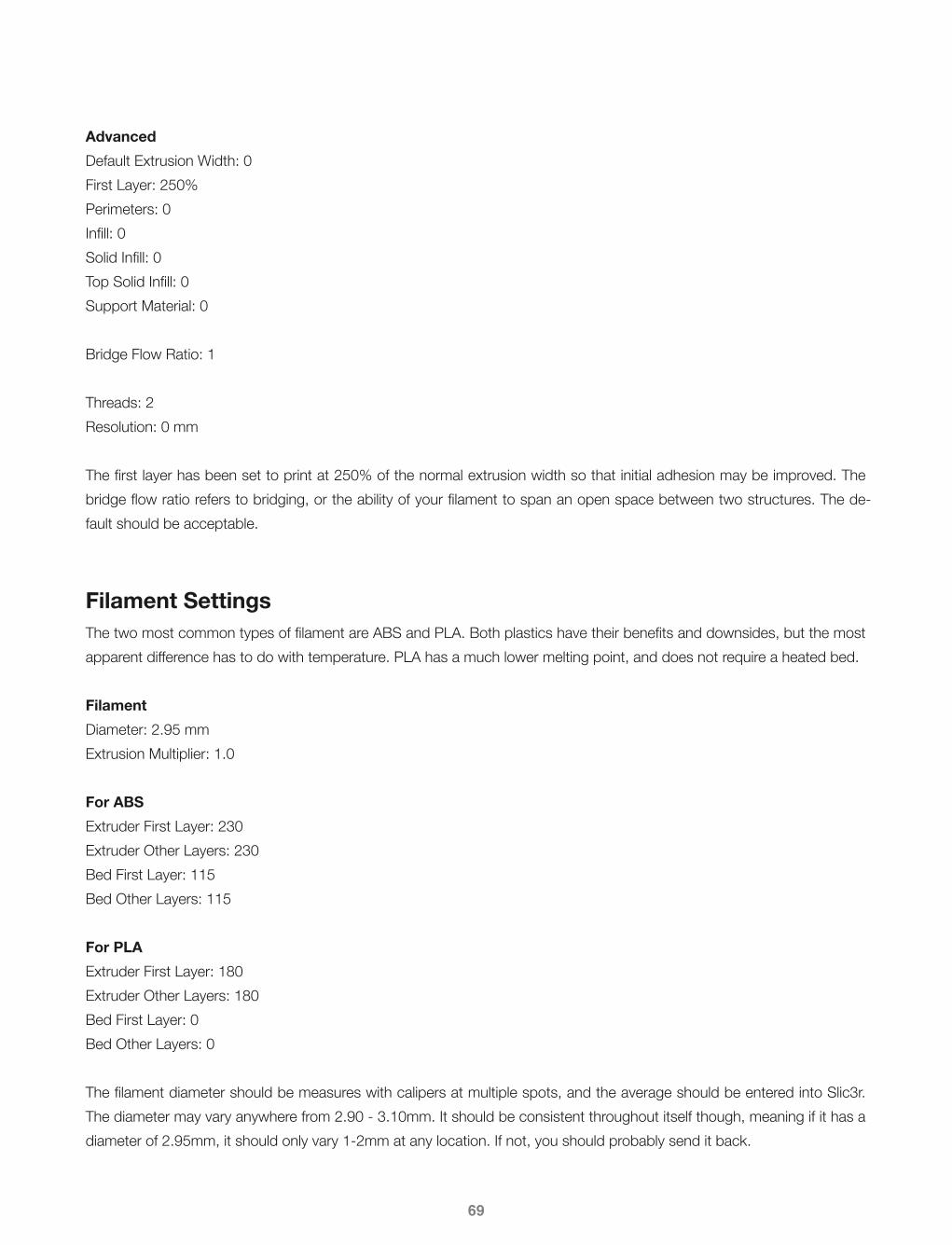
AdvancedDefault Extrusion Width: 0First Layer: 250%Perimeters: 0Infill: 0Solid Infill: 0Top Solid Infill: 0Support Material: 0
Bridge Flow Ratio: 1
Threads: 2Resolution: 0 mm
The first layer has been set to print at 250% of the normal extrusion width so that initial adhesion may be improved. The bridge flow ratio refers to bridging, or the ability of your filament to span an open space between two structures. The de-fault should be acceptable.
Filament SettingsThe two most common types of filament are ABS and PLA. Both plastics have their benefits and downsides, but the most apparent difference has to do with temperature. PLA has a much lower melting point, and does not require a heated bed.
FilamentDiameter: 2.95 mmExtrusion Multiplier: 1.0
For ABSExtruder First Layer: 230Extruder Other Layers: 230Bed First Layer: 115Bed Other Layers: 115
For PLAExtruder First Layer: 180Extruder Other Layers: 180Bed First Layer: 0Bed Other Layers: 0
The filament diameter should be measures with calipers at multiple spots, and the average should be entered into Slic3r. The diameter may vary anywhere from 2.90 - 3.10mm. It should be consistent throughout itself though, meaning if it has a diameter of 2.95mm, it should only vary 1-2mm at any location. If not, you should probably send it back.
69

As for the variances between ABS and PLA, note that the PCB Heatbed is not required if you are printing PLA, and that the extrusion temperature is much lower. ABS may be better for certain situations that require a higher heat tolerance how-ever, so think about the application prior to choosing a filament.
CoolingKeep Fan Always On: YesEnable Auto Cooling: No
Fan Speed Min: 35Fan Speed Max: 60Disable Fan For The First: 3 Layers
Enable Fan If Layer Print Time Is Below: 60 approximate secondsSlow Down If Layer Print Time Is Below: 5 approximate secondsMin Print Speed: 10 mm/s
A fan is recommended, but not required, for the Extruder Nozzle. The J-Head type hotend works best when the top en-trance (where the filament enters the hotend) is kept cool, so a fan helps the filament feed smoothly, which gives your print the best possible resolution. It is also recommended that a fan be used to cool the actual part being printed. This de-pends greatly on the type of part being printed, but for all parts, a fan does help keep the entire part at a more uniform temperature, which in turn helps prevent contraction which may lead the part to pop of the heatbed prematurely.
Printer SettingsThese settings help define your printer - the nozzle size, print area, etc.
GeneralBed Size X: 200 mmBed Size Y: 200 mmPrint Center X: 100 mmPrint Center Y: 100 mmZ Offset: 0 mm
G-Code Flavor: RepRap (Marlin/Sprinter/Repetier)Use Relative E Distances: No
Extruders: 1
Vibration Limit: 0 Hz
The bed size refers to the actual printable area on your heatbed. It should be as close to 200mm x 200mm as possible in order to maximize your print area. If you are only able to print on a smaller area, try to make adjustments to the bed or the frame to maximize the build volume.
70

Custom G-CodeStart G-Code:G28 ; home all axesG92 E0 ; reset extruderG1 E3 F1200 ; prime extruder 3mmG1 E2 F1200 ; retract extruder 3mmG92 E0 ; reset extruder
End G-Code:G1 X30.0 F4000G1 Y170 F4000M104 S0 ; turn off extruderM140 S0 ; turn off bedM84 ; disable motors
Layer Change G-Code:N/A
Tool Change G-Code:N/A
The tart G-Code uses some commands to get the printer ready. The commands are defined on the right side, which should give an idea of what each command does. For the end G-Code, notice how the first line has G1 followed by X30.0. This means that once the print is finished, the first thing the nozzle will do is move in the X direction to a position of +30.0. I chose this line because at the very top of the triangulated Prusa frame, the extruder motor hits the rods before the nozzle is able to reach X = 0. This collision is problematic, so to prevent it I keep the X from reaching it’s home posi-tion. It is because of this that it is important you check the build volume of your part before printing, to ensure that it will not crash with any of the frame components.
Extruder 1Nozzle Diameter: 0.35 mmExtruder Offset: x=0, y=0Length: 1Lift Z: 0.2Speed: 30 mm/sExtra Length on Restart: 0 mmMin Travel After Retraction: 2 mmRetract On Layer Change: YesWipe Before Retract: No
The nozzle diameter should be given by manufacturer, but double check using calipers. Lift Z raises the nozzle by the layer height amount before each layer change, which gives surprisingly cleaner results. Once your Slic3r settings are fin-ished, you can now export your .gcode file which will be loaded into and run using Pronterface.
71
72
3.4 · Modeling Software
Before starting your print, you must have something to print in the first place. One of the best places to look is Thingiverse.com. Supported by Makerbot, Thingiverse is a marketplace where members can share models freely between each other. Most members offer models n the .STL format, ready to be sliced by your own choice of G-Code generator. Some may even offer the model in .STEP or .STP formats, which you can edit in many common modeling programs. If you cannot find what you are looking for, it seems the best option is to model it yourself. In keeping with the open source theme, I am going to list a few modeling programs, all of which are free to use, and/or open source.
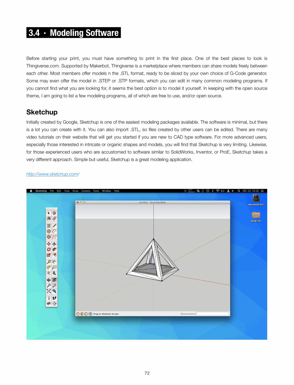
SketchupInitially created by Google, Sketchup is one of the easiest modeling packages available. The software is minimal, but there is a lot you can create with it. You can also import .STL, so files created by other users can be edited. There are many video tutorials on their website that will get you started if you are new to CAD type software. For more advanced users, especially those interested in intricate or organic shapes and models, you will find that Sketchup is very limiting. Likewise, for those experienced users who are accustomed to software similar to SolidWorks, Inventor, or ProE, Sketchup takes a very different approach. Simple but useful, Sketchup is a great modeling application.
http://www.sketchup.com/

Autodesk Fusion 360 (Previously Inventor Fusion)Autodesk Inventor Fusion is a limited free version of the pro level Inventor software. Unfortunately, Inventor is no longer available for download, as it has been replaced by Fusion 360. It is my understanding that Fusion 360 is the beginning of a cloud based transition of all of AutoDesk’s products, and I’m sure at some point it will no longer be free. In my opinion, Fusion 360 is kind of burdensome as you must have an internet connection and the program runs from the cloud essen-tially. It is kind of a strange approach, so who knows if Fusion 360 (as it is currently structured) will be around for very long. Given all of that, Fusion 360 is still a great solution to most modeling problems, as it has the an interface similar to what you would be used to if you are familiar with SolidWorks or Inventor, and it has most of the features you would be used to with top level modeling software. Of course, .STL import is included, so working with common printer model files is very simple.
http://www.autodesk.com/products/fusion-360/free-trial
73

Autodesk 123D Design123D Design is a bare bones basic modeling program offered by AutoDesk. While it is not as feature rich as Fusion 360, and most certainly nowhere close to Inventor, it offers an intuitive interface and allows you to create most basic types of models. 123D Design is offered as an online application, as well as a desktop application. The desktop version has even less features than the online version however (no import function on the desktop version), so if you want to get an .STL file into 123D Design on your desktop, you would have to import it into the online version, save it as one of your models, log in to your account on the desktop version, then open the saved model. At that point you might as well just work in the on-line application (assuming you have an internet connection at the time). Overall not a bad application, and it appears they are gearing it specifically to a 3D printing/rapid prototyping crowd, which is good, as improvements will most likely make the printing workflow even smoother.
http://www.123dapp.com/design
74

BlenderBlender is a very powerful open source modeling application designed for 3D animation. This is good because it has a TON of creative features unlike every other engineering based modeling program. This is also bad though, because it has a user interface unlike anything in the engineering world. This popular program has seen many revisions and up-dates, and it seems like there is a lot of user interest in improvements, so I have no doubts it will only get better over time. For the first time user, there is a very steep learning curve just to start making simple models, but if you can stick with it, there is a lot of potential to make some great models and organic sculptures, which is exciting when combined with a 3D printer. This program does import .STL, so printer friendly files are easy to manipulate within Blender. There is also a heavily populated and very active forum, along with a host of video tutorials, so if you want to invest the time, you can create some great models.
http://www.blender.org/
75

PRINTING & TROUBLESHOOTING4Given the previous Chapter, the overall process from model to printer should be somewhat clear by now. But how do we get the printer to work well? In order to get your prints to turn out how you want, you must first have a properly calibrated machine. The following Sections will take through how to calibrate the machine, how to troubleshoot any problems you may have, and some techniques on how to achieve different surface finishes.
76

77
4.1 · Calibration
Once you start printing, you may get a variety of results. If you are lucky, you will have a perfect print right from the start. IF you are like everyone else though, you will get a small wad of filament. See my initial printing progression in Fig. 4.1 be-low:
My first couple of prints were just small tangles of plastic, then I started to get the progression seen above. Within the day I was able to get usable prints.
Bed LevelingOne of the first things you should do prior to starting your print is to check that the print bed is level. To do so, lower the nozzle (via the Z-axis buttons in Pronterface) so that the tip is just about to touch the print surface. A good measure of how far the nozzle should be above the bed is to slide a piece of paper between the two. Lower the nozzle until the paper will slide with the nozzle when you move the X-carriage in the x and y directions. Start at one corner of the bed, setting the nozzle so it is a papers thickness above the bed. Then move the nozzle in either the x or y direction. The piece of pa-per should slide with the nozzle. If it does not slide with the nozzle, raise that corner of the bed until it does. If the nozzle tears through the paper, lower the bed at that corner until the paper slides without being torn. Repeat this process for all four corners of the print bed. Take your time, as the print height is critical to have your print stick to the print surface.
Extruder CalibrationFirst, you must calibrate your extruder. The idea is that when your G-Code tells the printer to extrude x-amount of material for the first layer, that exact amount should come out. If it is too thin, your layers will not stick together. Too thick, and you may get a jam in the nozzle, or the part will lack significant resolution.
Fig. 4.1

Power up your printer, open Pronterface, and select the Extrude button repeatedly until you get a smooth stream of fila-ment exiting the nozzle tip.
By default, pronterface is set up to extrude 5mm of filament at a time. Do not change this number. Using calipers, meas-ure out 60mm of filament from the top of the Extruder Body. Mark it with a piece of tape. Select the Extrude button a total of 6 times, pausing briefly between each selection to allow the filament to be extruded. Your printer should have extruded 30mm of filament. Measure from the base of the Extruder Body to the tape marker placed previously. Your calipers should read 30mm now. Chances are they will be slightly off, in which case you should now adjust your firmware accordingly.
If you recall to Section 3.1, the default value for extruder motor steps required to extrude 1mm of filament was 700. If your printer was spot on, you will have a total step value of:
700Steps /mm ⋅ 30mm = 21,000Steps
Let’s assume that once you extruded 30mm of filament, you recorded a measurement of 28.5mm. Now, to calculate the correct step value:
21,000Steps28.5mm
= 736.84Steps /mm
You will then open your Sprinter.ino file (.ino becomes the filetype once you save within Arduino), select the configuration.h tab, then change the E steps value to 736.84 steps. If you measured a calibration value greater than 30mm, you will get a value less than 700 when performing the calculations above.
For more information on Prusa calibration, visit the RepRap.org Calibration page
http://reprap.org/wiki/Calibration
or the very thorough blog by RichRap on properly calibrating your printer for use with Slic3r:
http://richrap.blogspot.com/2012/01/slic3r-is-nicer-part-1-settings-and.html
Temperature ControlAs mentioned previously, PLA and ABS differ greatly in their extrusion properties, mainly due to their melting points. Again, typical temperatures will be as follows:
PLA Extruder Heater: 180℃PLA PCB Heatbed: 0℃ (note: the heatbed will simply not turn on, leaving the bed at room temperature)
78

ABS Extruder Heater: 230℃ABS PCB Heatbed: 110℃
Similarly, the heatbed surface should be treated according to the filament type. For PLA, simple blue painters tape is per-haps the best solution. PLA will adhere very well to this surface, it is easily sourced, and it is not too expensive. Other op-tions include roughening the surface of the glass plate, so that the filament will have something to adhere to.
For ABS, I have found that PET based vehicle window tint works very well, and lasts relatively long before it must be re-placed. To source the tint film, I went to my local window tint shop, explained to the shop owner the nature of my project, showed him some build pictures, and he gave me a few scrap rolls that should last me for years. It helped that I actually got my windows tinted at his shop not too long before he gave me the tint film, but I don’t see why a shop owner wouldn’t give you a few pieces they were most likely going to trash anyway.
Another surface treatment for ABS is commonly referred to as “ABS juice.” To create some ABS juice of your own, you will simply dissolve an unspecified amount of ABS filament in acetone, creating a thin ABS/acetone slurry. You can then spray it onto the glass or simply pour it and spread it around. I have yet to make ABS juice since I experienced success with the PET based tint film, but it seems like a popular option that has garnered consistent results.
Fig. 4.2 above shows an ABS print, 0.2mm layer height.
79
Fig. 4.2

80
4.2 · Troubleshooting
There are a lot of things that can go wrong with your printer, and the key is being able to recognize the problem so that you may find the solution. The best place to look, aside from using the initial Google search, would be the RepRap fo-rums:
http://forums.reprap.org/
Search the forums thoroughly, as someone most likely has experienced the same problem before, especially since the Prusa i2 has achieved such popularity.
Filament Not Sticking To BedIf your heatbed surface is untreated, it will be very difficult to get the extruded filament to stick (even though some users have done it). Make sure you are using an appropriate method for getting the filament to stick, and if your tape is old or worn, try replacing it. Another cause might be that the nozzle is not close enough to the print bed surface. The filament should be squished down onto the plate by the nozzle. If the nozzle is too high, the filament will not be pressed onto the surface.
Filament Too Thin/ThickIf the extruded filament comes out of the nozzle too thick or thin, the extruder steps/mm may be set to an incorrect value. Repeat the extruder calibration steps as outlined previously. Once the corrected value has been entered, extrude material to verify the problem has been corrected.
Filament Intermittently Stops ExtrudingI experienced this problem, and it took me some time to figure out. The problem was that for any given layer, the filament would be extruded by the correct amount, then at a constant interval it would be extruded at a reduced rate for a short period of time (a matter of seconds). The problem was a partially clogged hobbed bolt. The intervals had to do with the rotation of the bolt itself. As it would rotate, the teeth would grab the filament and push it out of the nozzle tip. A small part of the hobbed bolt was clogged with tiny slivers of filament however, so when that part would rotate into posi-tion it would not grab the filament. The filament therefore would not get pushed out until the hobbed bolt rotated to the next unclogged section. The print would look like Fig. 4.4 to the right. Notice the evenly spaced strips of decreased filament.
Fig. 4.4

Filament Not Exiting NozzleIf this occurs, you may be experiencing a nozzle jam. A small piece of debris may have made its way to the nozzle tip, clogging the hole and preventing any filament from exiting. Some users have notices tiny metal balls inside their transpar-ent filament upon close inspection. If your filament is transparent, give it a quick once over before sticking in your printer. If your filament is opaque, you should simply hope you bought some of the good stuff. 1kg (2.2lbs) of filament usually costs around $30-40 (or more if you get it from better established sources i.e. Makerbot or Ultimaker). If you find a deal on 1kg of filament for less than $20 I would be very weary. Purity of the filament is very important, but so is diameter consistency, so while having a lot of colors is fun, try not to skimp on the filament quality.
Printed Parts Have Surface PitsFilament should be kept in a warm, dry environment. If it is exposed to extreme humidity or extreme cold the filament may become saturated with water. When printing, the water will evaporate leaving small voids in the print surface.
Motors Skip or StopIf the motors skip and restart, or stop altogether, the most likely cause is that the stepper motor driver got too hot and shut off to protect itself. Make sure you are using a fan on your RAMPS components, and that the air blows freely over the stepper drivers.
For even more information regarding troubleshooting, see the RepRap pictorial troubleshooting page:
http://reprap.org/wiki/Print_Troubleshooting_Pictorial_Guide
81

82
4.3 · Surface Finish
One of the most prominent complaints of 3D printed objects has to be regarding the surface finish. When printing with a layer height of 0.3mm or 0.2mm you can clearly see the layers, and it gives the finished object a very distinct texture, which, under most circumstances, is undesirable. When printing at a layer height of 0.1mm with a well calibrated ma-chine, the layers are harder to see and feel, as the object almost has a completely smooth finish. However, a 0.1mm layer height is not always practical, as it greatly increases print times, and sometime the model does not require that level of de-tail.
SandingOne option is to smooth the surface by hand, using filler such as bondo or epoxy, and sanding the surface smooth. This method is extremely difficult when the object has details, especially those small in nature. It is also tedious, and not feasi-ble for a run of many parts.
Acetone (By Brush - ABS ONLY)If there are specific areas of the object you want smooth, you can use acetone and a paintbrush to simply melt the plastic away. A small brush will give you a decent amount of control, but for a large part, or for many parts, this process is not as practical. Keep in mind that ABS is dissolvable in acetone while PLA is not, so this method has no effect on PLA printed objects. CAUTION: use a respirator when working with acetone for extended periods of time.
Acetone (By Vapor - ABS ONLY)This method is brilliant, and one that, in my opinion, changes the whole outlook on homemade 3D printers. To utilize this method, you will need a glass jar of some sort - some users have repurposed old coffee pots. You will pour a small amount of acetone into the jar, then place the jar on a hot plate of some sort - some users place the jar on a stovetop, or the PCB Heatbed. The acetone will heat up and turn into vapor. This vapor is less dense than air however, so it lingers near the bottom of the jar. You will then insert your ABS object into the jar, usually on a stand of some sort. Let it sit in the vapor for anywhere from a few seconds to a few minutes - it depends on the size of the object, and how much material you care to melt away. Keep in mind that the longer the object sits in the vapor, the smoother (and glossier) the finish will be, but the more detail and resolution will be lost, so figure out whether smoothness or detail is more important for that particular part. The parts will continue to “melt” for a time after you pull it out of the va-por, so give it ample time to dry before han-dling. CAUTION: acetone is FLAMMABLE so handle carefully. Also, use a respirator when working with acetone for extended periods of time.
Fig. 4.3 to the right shows (L to R) 0.3mm layer height part after acetone vapor bath, 0.1mm layer height part untreated, 0.3mm layer height part untreated.
Fig. 4.3

IMPROVEMENTS & UPGRADES5The Prusa i2 was Josef Prusa’s take on the RepRap Mendel. He has since designed the third iteration Prusa, the Prusa i3. While the i3 is an overall improved printer design, the Prusa i2 is still widely used for its simplicity, reliability, and the depth of documentation on the build process. Once you build your Prusa i2, you know doubt will have a lost of improvements you would like to make to your printer, and the great thing is you can print those improvements yourself!
In Section 1.1 of the parts acquisition list, many components are listed as upgraded parts in place of the standard Prusa i2 parts. There are a host of upgraded components available on Thingiverse.com, and if there are any changes you can envision, you can design and print them on your own, then share them on Thingiverse.com as well.
Frame DesignOne of the biggest complaints I have about the Prusa i2 is the frame design in combination with Wade’s Extruder. The ex-truder positions the E-motor at such an angle that it juts out the side. As the X-carriage moves upward during the print, the E-motor will eventually contact the top of the frame triangles if it travels too far in the + or - X directions. This problem has thoroughly been addressed in the design changes of the Prusa i3, so take this into consideration before you choose what printer to build.
Another newer printer is the Mendel Max 2. This printer has a similar design to the Prusa i3, but the frame appears to be slightly more robust, if not as refined as the Prusa i3.
Print AreaAlmost all popular RepRap designs utilize the 200mm x 200mm PCB Heatbed. The Prusa i3, among others, increases the vertical print range, giving a print volume of nearly 8 million cubic millimeters (200mm x 200mm x 200mm). If you wish to design your own printer concept, one approach is to establish the printer as a PLA only printer, which allows you to use a printbed of any size, as you are no longer restricted by the heated bed requirement.
PortabilityOne big benefit of the newer Prusa i3 is that the frame is collapsible, allowing the user to pack it in a large computer bag for travel. The Prusa i2 can be a portable workstation if the electronics and PSU are mounted to the frame, which many users have done. The best examples of great design and portability would have to be the Makerbot Replicator 2 and the Ultimaker2 - all components are enclosed in a well designed case.
83

REFERENCES6The following resources were used throughout this project, whether it be for parts acquisition or insight with a printing is-sue. Note that these sites in no way represent my opinions or beliefs, and are not to be interpreted as a party to this pro-ject or the information shared within.
•RepRap.org. University of Bath. 13 October 2013. Web. 11 December 2013
•Thingiverse.com. Makerbot Industries, LLV. 2013. Web. 11 December 2013
•RepRap-USA.com. 2013. Web. 11 December 2013
•Slic3r.org. 2013. Web. 11 December 2013
• RichRap. (2012, January 6). Slic3r is Nicer - Part 1 - Settings and Extruder Calibration. Retrieved from http://richrap.blogspot.com/2012/01/slic3r-is-nicer-part-1-settings-and.html
•Les Johnston. (2013, September 15). 3D Print ABS acetone vapour bath to finish the final product. Retrieved from http://3d-delta-reprap-southafrica.blogspot.com/2013/09/3d-print-abs-acetone-vapour-bath-to.html
•Sketchup. Trimble Navigation Limited. 2013. Web. 11 December 2013
•123D Design. Autodesk, Inc. 2013. Web. 11 December 2013
•Github. Github, Inc. 2013. Web. 11 December 2013
84