Building Bylaw #11364 & 11687: Book I - Insert...
282
Building By-law #11364 & 11687: Book I - Insert Pages Revision: Dec 20, 2016 Effective: May 1, 2017 Legend: Greybar text is Unique to Vancouver Purple text are #11364 changes. Red text are #11687 changes effective May 1, 2017. Orange text are errata to By-laws #11070. Blue text are errata to By-laws #11180 & #11687 . Struckout text is not to be read as part of the by-law, but is provided as an administrative convenience to show where a change has occurred. Instructions: Insert pages between successive pages as numbered (i.e. page 4a or 4b is inserted between pages 4 & 5). Specifics instructions may also be included after the header in [backets]. It is suggested that Division C of Book I - Volume 1, be moved to the beginning of Book I - Volume 2 to make room for the inserted pages. Book I - Replacement Pages : March 14, 2017
Transcript of Building Bylaw #11364 & 11687: Book I - Insert...

Building By-law #11364 & 11687: Book I - Insert Pages
Revision: Dec 20, 2016 Effective: May 1, 2017
Legend: Greybar text is Unique to Vancouver Purple text are #11364 changes. Red text are #11687 changes effective May 1, 2017. Orange text are errata to By-laws #11070. Blue text are errata to By-laws #11180 & #11687 .
Struckout text is not to be read as part of the by-law, but is provided as an administrative convenience to show where a change has occurred.
Instructions: Insert pages between successive pages as numbered (i.e. page 4a or 4b is inserted between pages 4 & 5). Specifics instructions may also be included after the header in [backets].
It is suggested that Division C of Book I - Volume 1, be moved to the beginning of Book I - Volume 2 to make room for the inserted pages.
Book I - Replacement Pages : March 14, 2017

[This page intentionally left blank]
Book I - Replacement Pages : March 14, 2017

[This page intentionally left blank]
Book I - Replacement Pages : March 14, 2017

Div. A, 1.1.1.1.(1) Application of this By-law
1) This By-law applies to any one or more of the following: a) the design and construction of a new building, b) the occupancy of any building, c) a change in occupancy of any building, d) an alteration of any building, e) an addition to any building, f) the demolition of any building, g) the reconstruction of any building that has been damaged by fire, earthquake or other cause, h) the correction of an unsafe condition in or about any building, i) all parts of any building that are affected by a change in occupancy, j) the work necessary to ensure safety in parts of a building i) that remain after a demolition, ii) that are affected by but that are not directly involved in alterations, or iii) that are affected by but not directly involved in additions, k) except as permitted by the Fire By-law, the installation, replacement, or alteration of materials or equipment regulated by this By-law, l) the work necessary to ensure safety in a relocated or removed building during and after relocation or removal, m) safety during construction of a building, including protection of the public, n) the design, installation, extension, alteration, renewal or repair of plumbing systems, o) the alteration, rehabilitation and change of occupancy of heritage buildings, p) the design and construction of a marina, q) the alteration of a marina, and r) retaining structures greater than 1.2 m in height.
(See Appendix A). Page 4b
Book I - Replacement Pages : March 14, 2017

[This page intentionally left blank]
Book I - Replacement Pages : March 14, 2017
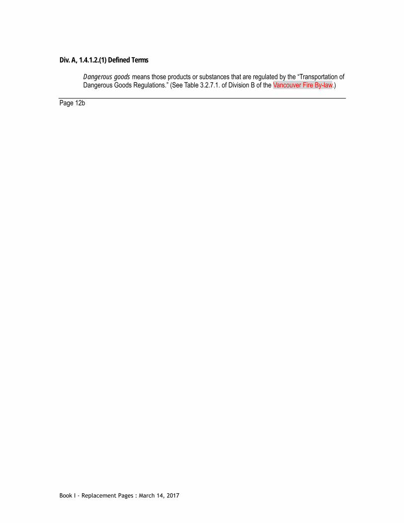
Div. A, 1.4.1.2.(1) Defined Terms
Dangerous goods means those products or substances that are regulated by the “Transportation of Dangerous Goods Regulations.” (See Table 3.2.7.1. of Division B of the Vancouver Fire By-law.)
Page 12b
Book I - Replacement Pages : March 14, 2017

[This page intentionally left blank]
Book I - Replacement Pages : March 14, 2017

Div. B, 1.1.3.1.(1) Climatic and Seismic Values
1) Except as required by Sentence (3), the climatic and seismic values required for the design of buildings under this By-law shall be in conformance with Table 1.1.3.1.A and Table 1.1.3.1.B.
Page 36b
Book I - Replacement Pages : March 14, 2017

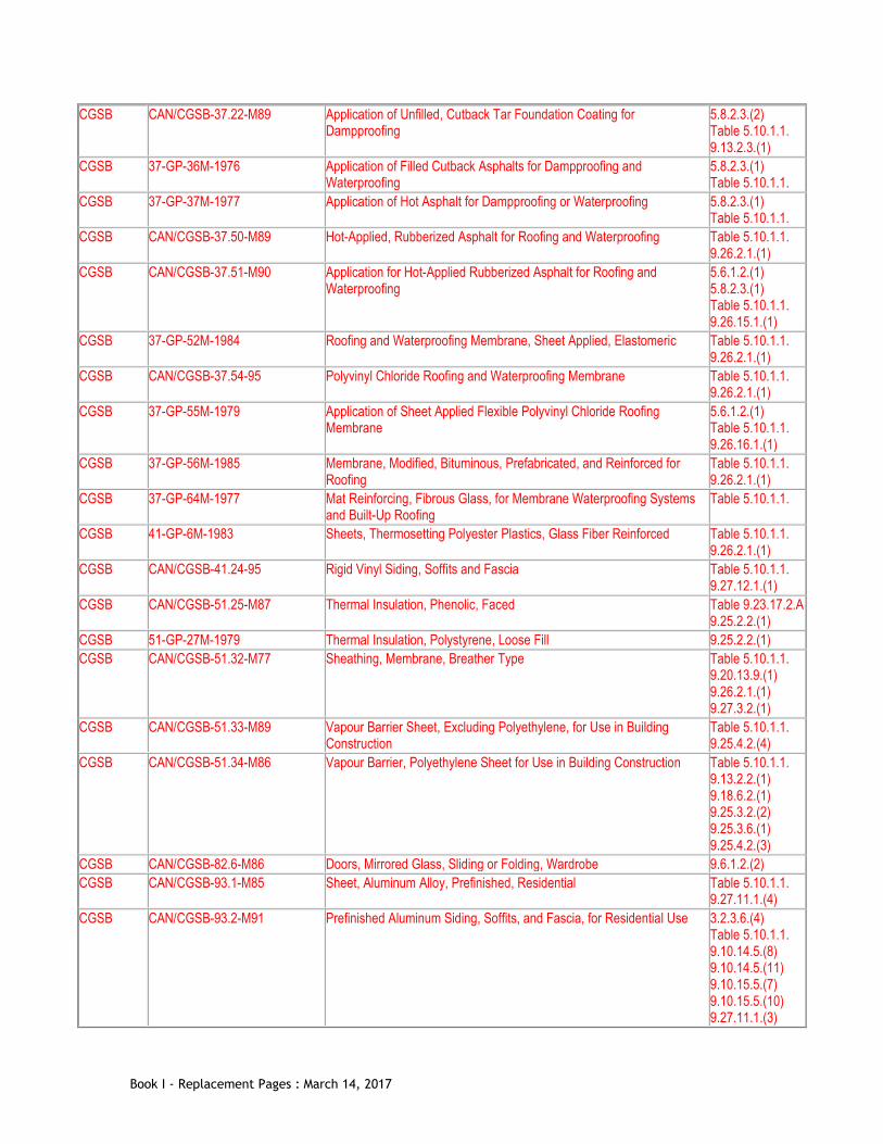
Div. B, Table 1.3.1.2.(1) Documents Referenced in Book I [Instruction: Replace Table 1.3.1.2. with the following]
Table 1.3.1.2. Documents Referenced in the Book I (General) of the Building By-law
Forming part of Sentence 1.3.1.2.(1) Issuing Agency Document Number(1) Title of Document(2) By-law
Reference AISI S201-07 North American Standard for Cold-Formed Steel Framing - Product Data 9.24.1.2.(1) ANSI A208.1-2009 Particleboard Table 5.10.1.1.
9.23.15.2.(3) 9.29.9.1.(1) 9.30.2.2.(1)
ANSI/ ASHRAE
62.1-2001 (except Addendum n) Ventilation for Acceptable Indoor Air Quality 6.2.2.1.(2)
ANSI/ ASHRAE/ IESNA
90.1-2010 Energy Standard for Buildings Except Low-Rise Residential Buildings 10.2.1.1.(1)(a)
ASME B18.6.1-1981 Wood Screws (Inch Series) Table 5.10.1.1. 9.23.3.1.(3)
ASME/CSA ASME A17.1-2007/CSA B44-10 Safety Code for Elevators and Escalators 3.2.6.7.(2) 3.5.2.1.(3) 3.5.4.2.(1) 3.8.3.10.(1) Table 4.1.5.11.
ASTM A 123/A 123M-09 Zinc (Hot-Dip Galvanized) Coatings on Iron and Steel Products Table 5.10.1.1. Table 9.20.16.1.
ASTM A 153/A 153M-09 Zinc Coating (Hot-Dip) on Iron and Steel Hardware Table 5.10.1.1. Table 9.20.16.1.
ASTM A 252-10 Welded and Seamless Steel Pipe Piles 4.2.3.8.(1) ASTM A 283/A 283M-03 Low and Intermediate Tensile Strength Carbon Steel Plates 4.2.3.8.(1) ASTM A 653/A 653M-11 Steel Sheet, Zinc-Coated (Galvanized) or Zinc-Iron Alloy-Coated
(Galvannealed) by the Hot-Dip Process Table 5.10.1.1. 9.3.3.2.(1)
ASTM A 792/A 792M-10 Steel Sheet, 55% Aluminum-Zinc Alloy-Coated by the Hot-Dip Process 9.3.3.2.(1) ASTM A 1008/A 1008M-11 Steel, Sheet, Cold-Rolled, Carbon, Structural, High-Strength Low-Alloy,
High-Strength Low-Alloy with Improved Formability, Solution Hardened, and Bake Hardenable
4.2.3.8.(1)
ASTM A 1011/A 1011M-10 Steel, Sheet and Strip, Hot-Rolled, Carbon, Structural, High-Strength Low-Alloy, High-Strength Low-Alloy with Improved Formability, and Ultra-High Strength
4.2.3.8.(1)
ASTM C 4-04 Clay Drain Tile and Perforated Clay Drain Tile Table 5.10.1.1. 9.14.3.1.(1)
ASTM C 27-98 Classification of Fireclay and High-Alumina Refractory Brick 9.21.3.4.(1) ASTM C 73-10 Calcium Silicate Brick (Sand-Lime Brick) Table 5.10.1.1.
9.20.2.1.(1) ASTM C 126-11 Ceramic Glazed Structural Clay Facing Tile, Facing Brick, and Solid
Masonry Units Table 5.10.1.1. 9.20.2.1.(1)
ASTM C 212-10 Structural Clay Facing Tile Table 5.10.1.1. 9.20.2.1.(1)
ASTM C 260/C 260M-10a Air-Entraining Admixtures for Concrete 9.3.1.8.(1)
Book I - Replacement Pages : March 14, 2017

ASTM C 411-11 Hot-Surface Performance of High-Temperature Thermal Insulation 3.6.5.4.(4) 3.6.5.5.(1) 9.33.6.4.(4) 9.33.8.2.(2)
ASTM C 412M-11 Concrete Drain Tile (Metric) Table 5.10.1.1. 9.14.3.1.(1)
ASTM C 444M-03 Perforated Concrete Pipe (Metric) Table 5.10.1.1. 9.14.3.1.(1)
ASTM C 494/C 494M-11 Chemical Admixtures for Concrete 9.3.1.8.(1) ASTM C 553-11 Mineral Fiber Blanket Thermal Insulation for Commercial and Industrial
Applications Table 5.10.1.1.
ASTM C 612-10 Mineral Fiber Block and Board Thermal Insulation Table 5.10.1.1. ASTM C 700-11 Vitrified Clay Pipe, Extra Strength, Standard Strength and Perforated Table 5.10.1.1.
9.14.3.1.(1) ASTM C 834-10 Latex Sealants Table 5.10.1.1.
9.27.4.2.(2) ASTM C 920-11 Elastomeric Joint Sealants Table 5.10.1.1.
9.27.4.2.(2) ASTM C 954-11 Steel Drill Screws for the Application of Gypsum Panel Products or Metal
Plaster Bases to Steel Studs from 0.033 in. (0.84 mm) to 0.112 in. (2.84 mm) in Thickness
9.24.1.4.(1)
ASTM C 991-08e1 Flexible Fibrous Glass Insulation for Metal Buildings Table 5.10.1.1. ASTM C 1002-07 Steel Self-Piercing Tapping Screws for the Application of Gypsum Panel
Products or Metal Plaster Bases to Wood Studs or Steel Studs Table 5.10.1.1. 9.24.1.4.(1) 9.29.5.7.(1)
ASTM C 1177/C 1177M-08 Glass Mat Gypsum Substrate for Use as Sheathing Table 5.10.1.1. Table 9.23.17.2.A
ASTM C 1178/C 1178M-11 Coated Glass Mat Water-Resistant Gypsum Backing Panel Table 5.10.1.1. 9.29.5.2.(1)
ASTM C 1184-05 Structural Silicone Sealants Table 5.10.1.1. 9.27.4.2.(2)
ASTM C 1311-10 Solvent Release Sealants Table 5.10.1.1. 9.27.4.2.(2)
ASTM C 1330-02 Cylindrical Sealant Backing for Use with Cold Liquid Applied Sealants Table 5.10.1.1. 9.27.4.2.(3)
ASTM C 1396/C 1396M-11 Gypsum Board 3.1.5.12.(4) Table 5.10.1.1. Table 9.23.17.2.A 9.29.5.2.(1) Table 9.29.5.3.
ASTM D 323-08 Vapour Pressure of Petroleum Products (Reid Method) 1.4.1.2.(1)(3) ASTM D 2178-04 Asphalt Glass Felt Used in Roofing and Waterproofing Table 5.10.1.1. ASTM D 2898-10 Accelerated Weathering of Fire-Retardant-Treated Wood for Fire Testing 3.1.5.5.(5)
3.1.5.21.(1) 3.2.2.50.(3) 3.2.3.7.(4) 9.10.14.5.(3) 9.10.15.5.(3)
ASTM E 90-04 Laboratory Measurement of Airborne Sound Transmission Loss of Building Partitions and Elements
5.9.1.1.(1) 9.11.1.1.(1)
Book I - Replacement Pages : March 14, 2017

ASTM E 96/E 96M-10 Water Vapour Transmission of Materials 5.5.1.2.(3) 9.25.4.2.(1) 9.25.5.1.(1) 9.30.1.2.(1)
ASTM E 336-05 Measurement of Airborne Sound Attenuation between Rooms in Buildings
5.9.1.1.(1) 9.11.1.1.(1)
ASTM E 413-04 Classification for Rating Sound Insulation 5.9.1.1.(1) 9.11.1.1.(1)
ASTM E 2190-10 Insulating Glass Unit Performance and Evaluation Table 5.10.1.1. 9.6.1.2.(1)
ASTM F 476-84 Security of Swinging Door Assemblies 9.7.5.2.(2) ASTM F 1667-05 Driven Fasteners: Nails, Spikes, and Staples 9.23.3.1.(1)
9.26.2.2.(1) 9.29.5.6.(1)
AWPA M4-11 Care of Preservative-Treated Wood Products 4.2.3.2.(2) Table 5.10.1.1.
City Fire By-law 1.1.1.1.(1)(3) 1.1.4.1.(1) 1.4.1.2.(1)(3) 2.1.1.2.(4)(3) 3.1.13.1.(1) 3.2.3.21.(1) 3.2.4.6.(1) 3.2.5.16.(1) 3.3.1.2.(1) 3.3.1.10.(1) 3.3.2.3.(1) 3.3.2.15.(1) 3.3.4.3.(4) 3.3.5.2.(1) 3.3.6.1.(1) 3.3.6.3.(1) 3.3.6.3.(2) 3.3.6.4.(1) 3.3.6.4.(2) 3.3.6.6.(1) 6.2.2.6.(1) 6.2.12.2.(3) 6.2.12.3.(1) 6.2.12.4.(1) 8.1.1.1.(3) 8.1.1.3.(1) 9.10.1.2.(1) 9.10.20.4.(1) 9.10.21.8.(1)
City Book II (Plumbing Systems) of the By-law 2.1.1.2.(4)(3) 5.6.2.2.(2) 7.1.2.1.(1) 9.31.6.2.(1)
BC R.S.B.C. 1996, c. 17 Architects Act 1.4.1.2.(1)(3)
Book I - Replacement Pages : March 14, 2017

BC B.C. Reg. 100/2004 Electrical Safety Regulation 3.3.6.2.(4) 3.6.1.2.(1) 3.6.2.1.(6) 3.6.2.7.(1) 6.2.1.4.(1) 9.31.6.2.(2) 9.33.5.2.(1) 9.34.1.1.(1)
BC B.C. Reg. 101/2004 Elevating Devices Safety Regulation 3.5.2.1.(1) 3.5.2.1.(2)
BC R.S.B.C. 1996, c. 116 Engineers and Geoscientists Act 1.4.1.2.(1)(3) BC B.C. Reg. 103/2004 Gas Safety Regulation 6.2.1.4.(1)
9.10.22.1.(1) 9.31.6.2.(2) 9.33.5.2.(1)
BC R.S.B.C. 1996, c. 323 Local Government Act 2.2.1.1.(1)(4) BC R.S.B.C. 1996, c. 293 Mines Act 1.4.1.2.(1)(3) BC S.B.C. 2003, c. 39 Safety Standards Act 6.2.1.4.(1)
6.2.1.4.(2) 9.31.6.2.(2) 9.33.5.2.(1) 9.33.5.2.(2)
BC B.C. Reg. 104/2004 Power Engineers, Boiler, Pressure Vessel and Refrigeration Safety Regulation
6.2.1.4.(1) 9.31.6.2.(2) 9.33.5.2.(1)
BNQ NQ 3624-115/2007 Polyethylene (PE) Pipe and Fittings – Flexible Pipes for Drainage – Characteristics and Test Methods
Table 5.10.1.1. 9.14.3.1.(1)
CCBFC NRCC 38732 National Farm Building Code of Canada 1995 1.1.1.1.(4) CCBFC NRCC 54435-2011 National Energy Code of Canada for Buildings 10.2.1.1. CGSB CAN/CGSB-1.501-M89 Method for Permeance of Coated Wallboard 5.5.1.2.(2)
9.25.4.2.(5) CGSB CAN/CGSB-7.2-94 Adjustable Steel Columns 9.17.3.4.(1) CGSB CAN/CGSB-10.3-92 Air Setting Refractory Mortar 9.21.3.4.(2)
9.21.3.9.(1) 9.22.2.2.(2)
CGSB CAN/CGSB-11.3-M87 Hardboard Table 5.10.1.1. 9.27.9.1.(2) 9.29.7.1.(1) 9.30.2.2.(1)
CGSB CAN/CGSB-11.5-M87 Hardboard, Precoated, Factory Finished, for Exterior Cladding Table 5.10.1.1. 9.27.9.1.(1)
CGSB CAN/CGSB-12.1-M90 Tempered or Laminated Safety Glass 3.3.1.19.(2) 3.4.6.15.(1) 3.4.6.15.(3) Table 5.10.1.1. 9.6.1.2.(1) 9.6.1.4.(1) 9.8.8.7.(1)
CGSB CAN/CGSB-12.2-M91 Flat, Clear Sheet Glass Table 5.10.1.1. 9.6.1.2.(1)
CGSB CAN/CGSB-12.3-M91 Flat, Clear Float Glass Table 5.10.1.1. 9.6.1.2.(1)
Book I - Replacement Pages : March 14, 2017

CGSB CAN/CGSB-12.4-M91 Heat Absorbing Glass Table 5.10.1.1. 9.6.1.2.(1)
CGSB CAN/CGSB-12.8-97 Insulating Glass Units Table 5.10.1.1. 9.6.1.2.(1)
CGSB CAN/CGSB-12.10-M76 Glass, Light and Heat Reflecting Table 5.10.1.1. 9.6.1.2.(1)
CGSB CAN/CGSB-12.11-M90 Wired Safety Glass 3.3.1.19.(2) 3.4.6.15.(1) 3.4.6.15.(3) Table 5.10.1.1. 9.6.1.2.(1) 9.6.1.4.(1) 9.8.8.7.(1)
CGSB CAN/CGSB-12.20-M89 Structural Design of Glass for Buildings 4.3.6.1.(1) 9.6.1.3.(1)
CGSB CAN/CGSB-19.21-M87 Sealing and Bedding Compound, Acoustical 9.11.3.1.(1) CGSB CAN/CGSB-19.22-M89 Mildew-Resistant Sealing Compound for Tubs and Tiles 9.29.10.5.(1) CGSB CAN/CGSB-34.22-94 Asbestos-Cement Drain Pipe Table 5.10.1.1.
9.14.3.1.(1) CGSB CAN/CGSB-37.1-M89 Chemical Emulsifier Type, Emulsified Asphalt for Dampproofing Table 5.10.1.1.
9.13.2.2.(1) CGSB CAN/CGSB-37.2-M88 Emulsified Asphalt, Mineral-Colloid Type, Unfilled, for Dampproofing and
Waterproofing and for Roof Coatings Table 5.10.1.1. 9.13.2.2.(1) 9.13.3.2.(1)
CGSB CAN/CGSB-37.3-M89 Application of Emulsified Asphalts for Dampproofing or Waterproofing 5.8.2.3.(1) Table 5.10.1.1. 9.13.2.3.(1) 9.13.3.3.(1)
CGSB CAN/CGSB-37.4-M89 Fibrated, Cutback Asphalt, Lap Cement for Asphalt Roofing Table 5.10.1.1. 9.26.2.1.(1)
CGSB CAN/CGSB-37.5-M89 Cutback Asphalt Plastic, Cement Table 5.10.1.1. 9.26.2.1.(1)
CGSB 37-GP-6Ma-1983 Asphalt, Cutback, Unfilled, for Dampproofing 5.8.2.2.(6) 5.8.2.2.(7) Table 5.10.1.1. 9.13.2.2.(1)
CGSB CAN/CGSB-37.8-M88 Asphalt, Cutback, Filled, for Roof Coating Table 5.10.1.1. 9.26.2.1.(1)
CGSB 37-GP-9Ma-1983 Primer, Asphalt, Unfilled, for Asphalt Roofing, Dampproofing and Waterproofing
Table 5.10.1.1. 9.26.2.1.(1)
CGSB 37-GP-12Ma-1984 Application of Unfilled Cutback Asphalt for Dampproofing 5.8.2.3.(2) Table 5.10.1.1. 9.13.2.3.(1)
CGSB CAN/CGSB-37.16-M89 Filled, Cutback Asphalt for Dampproofing and Waterproofing Table 5.10.1.1. 9.13.2.2.(1) 9.13.3.2.(1)
CGSB 37-GP-18Ma-1985 Tar, Cutback, Unfilled, for Dampproofing 5.8.2.2.(6) 5.8.2.2.(7) Table 5.10.1.1. 9.13.2.2.(1)
CGSB 37-GP-21M-1985 Tar, Cutback, Fibrated, for Roof Coating Table 5.10.1.1. 9.26.2.1.(1)
Book I - Replacement Pages : March 14, 2017
CGSB CAN/CGSB-37.22-M89 Application of Unfilled, Cutback Tar Foundation Coating for Dampproofing
5.8.2.3.(2) Table 5.10.1.1. 9.13.2.3.(1)
CGSB 37-GP-36M-1976 Application of Filled Cutback Asphalts for Dampproofing and Waterproofing
5.8.2.3.(1) Table 5.10.1.1.
CGSB 37-GP-37M-1977 Application of Hot Asphalt for Dampproofing or Waterproofing 5.8.2.3.(1) Table 5.10.1.1.
CGSB CAN/CGSB-37.50-M89 Hot-Applied, Rubberized Asphalt for Roofing and Waterproofing Table 5.10.1.1. 9.26.2.1.(1)
CGSB CAN/CGSB-37.51-M90 Application for Hot-Applied Rubberized Asphalt for Roofing and Waterproofing
5.6.1.2.(1) 5.8.2.3.(1) Table 5.10.1.1. 9.26.15.1.(1)
CGSB 37-GP-52M-1984 Roofing and Waterproofing Membrane, Sheet Applied, Elastomeric Table 5.10.1.1. 9.26.2.1.(1)
CGSB CAN/CGSB-37.54-95 Polyvinyl Chloride Roofing and Waterproofing Membrane Table 5.10.1.1. 9.26.2.1.(1)
CGSB 37-GP-55M-1979 Application of Sheet Applied Flexible Polyvinyl Chloride Roofing Membrane
5.6.1.2.(1) Table 5.10.1.1. 9.26.16.1.(1)
CGSB 37-GP-56M-1985 Membrane, Modified, Bituminous, Prefabricated, and Reinforced for Roofing
Table 5.10.1.1. 9.26.2.1.(1)
CGSB 37-GP-64M-1977 Mat Reinforcing, Fibrous Glass, for Membrane Waterproofing Systems and Built-Up Roofing
Table 5.10.1.1.
CGSB 41-GP-6M-1983 Sheets, Thermosetting Polyester Plastics, Glass Fiber Reinforced Table 5.10.1.1. 9.26.2.1.(1)
CGSB CAN/CGSB-41.24-95 Rigid Vinyl Siding, Soffits and Fascia Table 5.10.1.1. 9.27.12.1.(1)
CGSB CAN/CGSB-51.25-M87 Thermal Insulation, Phenolic, Faced Table 9.23.17.2.A 9.25.2.2.(1)
CGSB 51-GP-27M-1979 Thermal Insulation, Polystyrene, Loose Fill 9.25.2.2.(1) CGSB CAN/CGSB-51.32-M77 Sheathing, Membrane, Breather Type Table 5.10.1.1.
9.20.13.9.(1) 9.26.2.1.(1) 9.27.3.2.(1)
CGSB CAN/CGSB-51.33-M89 Vapour Barrier Sheet, Excluding Polyethylene, for Use in Building Construction
Table 5.10.1.1. 9.25.4.2.(4)
CGSB CAN/CGSB-51.34-M86 Vapour Barrier, Polyethylene Sheet for Use in Building Construction Table 5.10.1.1. 9.13.2.2.(1) 9.18.6.2.(1) 9.25.3.2.(2) 9.25.3.6.(1) 9.25.4.2.(3)
CGSB CAN/CGSB-82.6-M86 Doors, Mirrored Glass, Sliding or Folding, Wardrobe 9.6.1.2.(2) CGSB CAN/CGSB-93.1-M85 Sheet, Aluminum Alloy, Prefinished, Residential Table 5.10.1.1.
9.27.11.1.(4) CGSB CAN/CGSB-93.2-M91 Prefinished Aluminum Siding, Soffits, and Fascia, for Residential Use 3.2.3.6.(4)
Table 5.10.1.1. 9.10.14.5.(8) 9.10.14.5.(11) 9.10.15.5.(7) 9.10.15.5.(10) 9.27.11.1.(3)
Book I - Replacement Pages : March 14, 2017

CGSB CAN/CGSB-93.3-M91 Prefinished Galvanized and Aluminum-Zinc Alloy Steel Sheet for Residential Use
Table 5.10.1.1. 9.27.11.1.(2)
CGSB CAN/CGSB-93.4-92 Galvanized Steel and Aluminum-Zinc Alloy Coated Steel Siding, Soffits and Fascia, Prefinished, Residential
Table 5.10.1.1. 9.27.11.1.(1)
CSA CAN/CSA-6.19-01 Residential Carbon Monoxide Alarming Devices 6.2.4.1.(2) 9.32.4.2.(2) 9.32.4.2.(3)
CSA A23.1-09 Concrete Materials and Methods of Concrete Construction 4.2.3.6.(1) 4.2.3.9.(1) Table 5.10.1.1. 9.3.1.1.(1) 9.3.1.1.(4) 9.3.1.3.(1) 9.3.1.4.(1)
CSA CAN/CSA-A23.3-04 Design of Concrete Structures Table 4.1.8.9. 4.3.3.1.(1)
CSA CAN/CSA-A82.1-M87 Burned Clay Brick (Solid Masonry Units Made from Clay or Shale) Table 5.10.1.1. 9.20.2.1.(1)
CSA A82.4-M1978 Structural Clay Load-Bearing Wall Tile Table 5.10.1.1. 9.20.2.1.(1)
CSA A82.5-M1978 Structural Clay Non-Load-Bearing Tile Table 5.10.1.1. 9.20.2.1.(1)
CSA CAN3-A82.8-M78 Hollow Clay Brick Table 5.10.1.1. 9.20.2.1.(1)
CSA CAN/CSA-A82.27-M91 Gypsum Board 3.1.5.12.(4) Table 5.10.1.1. Table 9.23.17.2.A 9.29.5.2.(1)
CSA A82.30-M1980 Interior Furring, Lathing and Gypsum Plastering Table 5.10.1.1. 9.29.4.1.(1)
CSA A82.31-M1980 Gypsum Board Application 3.2.3.6.(4) Table 5.10.1.1. 9.10.12.4.(3) 9.10.14.5.(8) 9.10.14.5.(11) 9.10.15.5.(7) 9.10.15.5.(10) 9.29.5.1.(2)
CSA CAN3-A93-M82 Natural Airflow Ventilators for Buildings Table 5.10.1.1. 9.19.1.2.(5)
CSA A123.1-05/A123.5-05 Asphalt Shingles Made From Organic Felt and Surfaced with Mineral Granules/Asphalt Shingles Made From Glass Felt and Surfaced with Mineral Granules
Table 5.10.1.1. 9.26.2.1.(1)
CSA CAN/CSA-A123.2-03 Asphalt-Coated Roofing Sheets Table 5.10.1.1. 9.26.2.1.(1)
CSA A123.3-05 Asphalt Saturated Organic Roofing Felt Table 5.10.1.1. 9.26.2.1.(1)
CSA CAN/CSA-A123.4-04 Asphalt for Constructing Built-Up Roof Coverings and Waterproofing Systems
Table 5.10.1.1. 9.13.2.2.(1) 9.13.3.2.(1) 9.26.2.1.(1)
CSA A123.17-05 Asphalt Glass Felt Used in Roofing and Waterproofing Table 5.10.1.1. 9.26.2.1.(1)
Book I - Replacement Pages : March 14, 2017

CSA CAN3-A123.51-M85 Asphalt Shingle Application on Roof Slopes 1:3 and Steeper 5.6.1.2.(1) Table 5.10.1.1. 9.26.1.2.(1)
CSA CAN3-A123.52-M85 Asphalt Shingle Application on Roof Slopes 1:6 to Less Than 1:3 5.6.1.2.(1) Table 5.10.1.1. 9.26.1.2.(1)
CSA CAN/CSA-A165.1-04 Concrete Block Masonry Units Table 5.10.1.1. 9.15.2.2.(1) 9.17.5.1.(1) 9.20.2.1.(1) 9.20.2.6.(1)
CSA CAN/CSA-A165.2-04 Concrete Brick Masonry Units Table 5.10.1.1. 9.20.2.1.(1)
CSA CAN/CSA-A165.3-04 Prefaced Concrete Masonry Units Table 5.10.1.1. 9.20.2.1.(1)
CSA CAN3-A165.4-M85 Autoclaved Cellular Units Table 5.10.1.1. 9.20.2.1.(1)
CSA CAN/CSA-A179-04 Mortar and Grout for Unit Masonry Table 5.10.1.1. 9.15.2.2.(3) 9.20.3.1.(1)
CSA CAN/CSA-A220 Series-06
Concrete Roof Tiles Table 5.10.1.1. 9.26.2.1.(1) 9.26.17.1.(1)
CSA CAN/CSA-A324-M88 Clay Flue Liners 9.21.3.3.(1) CSA CAN/CSA-A371-04 Masonry Construction for Buildings 5.6.1.2.(2)
Table 5.10.1.1. 9.15.2.2.(3) 9.20.3.2.(7) 9.20.15.2.(1)
CSA CAN/CSA-A405-M87 Design and Construction of Masonry Chimneys and Fireplaces 9.21.3.5.(1) 9.22.1.4.(1) 9.22.5.2.(2)
CSA AAMA/WDMA/CSA 101/I.S.2/A440-08
NAFS – North American Fenestration Standard/Specification for Windows, Doors, and Skylights
5.10.2.2.(1) 5.10.2.2.(3) 9.7.4.1.(1) 9.7.4.2.(1) 9.7.4.3.(2) 9.7.5.1.(1) 9.7.5.3.(1)
CSA A440S1-09 Canadian Supplement to AAMA/WDMA/CSA 101/I.S.2/A440, NAFS – North American Fenestration Standard/Specification for Windows, Doors, and Skylights, as updated by update no. 1 (July 2013)
1.1.3.1.(2) 5.10.2.2.(1) 9.7.4.2.(1)
CSA CAN/CSA-A660-10 Certification of Manufacturers of Steel Building Systems 4.3.4.3.(1) CSA CAN/CSA-A3001-08 Cementitious Materials for Use in Concrete Table 5.10.1.1.
9.3.1.2.(1) 9.28.2.1.(1)
CSA CAN/CSA-B72-M87 Installation Code for Lightning Protection Systems 6.3.1.4.(1) CSA B111-1974 Wire Nails, Spikes and Staples 9.23.3.1.(1)
9.26.2.2.(1) 9.29.5.6.(1)
CSA B139-04 Installation Code for Oil-Burning Equipment 6.2.1.4.(1) 9.31.6.2.(2) 9.33.5.2.(1)
Book I - Replacement Pages : March 14, 2017

CSA CAN/CSA-B182.1-11 Plastic Drain and Sewer Pipe and Pipe Fittings Table 5.10.1.1. 9.14.3.1.(1)
CSA CAN/CSA-B214-12 Installation Code for Hydronic Heating Systems 6.2.1.1.(1) 9.33.4.2.(1)
CSA CAN/CSA-B355-09 Lifts for Persons with Physical Disabilities 3.8.3.10.(1) CSA CAN/CSA-B365-01 Installation Code for Solid-Fuel Burning Appliances and Equipment 6.2.1.4.(1)
9.22.10.2.(1) 9.31.6.2.(2) 9.33.5.3.(1)
CSA C22.1-15 Canadian Electrical Code, Part I 3.3.6.2.(4) 3.6.1.2.(1) 3.6.2.1.(6) 3.6.2.7.(1) 6.2.1.4.(1) 9.31.6.2.(2) 9.33.5.2.(1) 9.34.1.1.(1)
CSA C22.2 No. 0.3-09 Test Methods for Electrical Wires and Cables 3.1.4.3.(1) 3.1.4.3.(2) 3.1.5.18.(1) 3.1.5.18.(3) 9.34.1.5.(1)
CSA C22.2 No. 141-10 Emergency Lighting Equipment 3.2.7.4.(2) 3.4.5.1.(3) 9.9.11.3.(3) 9.9.12.3.(7)
CSA C22.2 No. 211.0-03 General Requirements and Methods of Testing for Nonmetallic Conduit 3.1.5.20.(1) CSA CAN/CSA-C22.2 No. 262-04 Optical Fiber Cable and Communication Cable Raceway Systems 3.1.5.20.(1) CSA CAN/CSA-C260-M90 Rating the Performance of Residential Mechanical Ventilating Equipment 9.32.3.5.(1)
9.32.3.6.(2) 9.32.3.7.(1)
CSA CAN/CSA-C282-09 Emergency Electrical Power Supply for Buildings 3.2.7.5.(1) CSA CAN/CSA-C448 Series-02 Design and Installation of Earth Energy Systems 9.33.5.2.(1) CSA F280-12 Determining the Required Capacity of Residential Space Heating and
Cooling Appliances 9.33.5.1.(1)
CSA CAN/CSA-F326-M91 Residential Mechanical Ventilation Systems 9.32.3.1.(1) CSA CAN/CSA-G30.18-09 Billet-Steel Bars for Concrete Reinforcement 9.3.1.1.(4) CSA CAN/CSA-G40.21-04 General Requirements for Rolled or Welded Structural Quality Steel 4.2.3.8.(1)
Table 5.10.1.1. 9.23.4.3.(2)
CSA CAN/CSA-G401-07 Corrugated Steel Pipe Products Table 5.10.1.1. 9.14.3.1.(1)
CSA CAN/CSA-O80 Series-08 Wood Preservation 3.1.4.5.(1) 4.2.3.2.(1) 4.2.3.2.(2) Table 5.10.1.1.
CSA CAN/CSA-O80.1-08 Specification of Treated Wood 9.3.2.9.(5) CSA CAN/CSA-O80.2-08 Processing and Treatment 4.2.3.2.(1) CSA CAN/CSA-O80.3-08 Preservative Formulations 4.2.3.2.(1) CSA O80.15-97 Preservative Treatment of Wood for Building Foundation Systems,
Basements, and Crawl Spaces by Pressure Processes 4.2.3.2.(1)
CSA O86-09 Engineering Design in Wood Table 4.1.8.9. 4.3.1.1.(1)
Book I - Replacement Pages : March 14, 2017
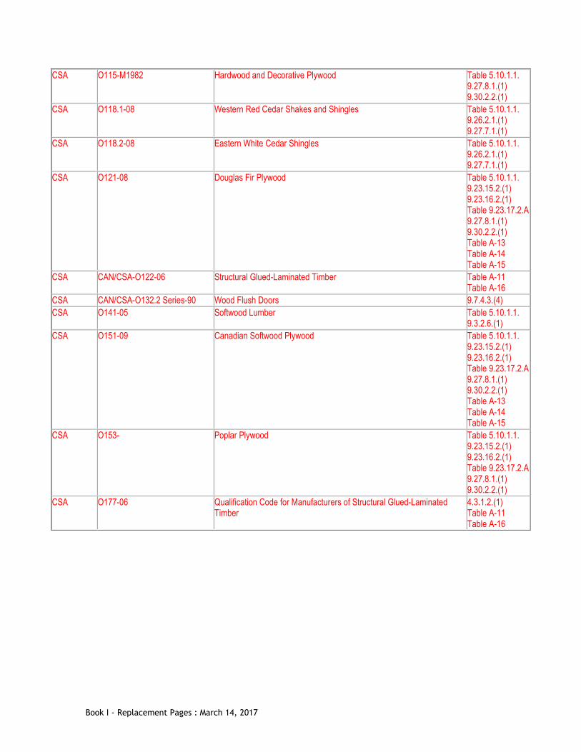
CSA O115-M1982 Hardwood and Decorative Plywood Table 5.10.1.1. 9.27.8.1.(1) 9.30.2.2.(1)
CSA O118.1-08 Western Red Cedar Shakes and Shingles Table 5.10.1.1. 9.26.2.1.(1) 9.27.7.1.(1)
CSA O118.2-08 Eastern White Cedar Shingles Table 5.10.1.1. 9.26.2.1.(1) 9.27.7.1.(1)
CSA O121-08 Douglas Fir Plywood Table 5.10.1.1. 9.23.15.2.(1) 9.23.16.2.(1) Table 9.23.17.2.A 9.27.8.1.(1) 9.30.2.2.(1) Table A-13 Table A-14 Table A-15
CSA CAN/CSA-O122-06 Structural Glued-Laminated Timber Table A-11 Table A-16
CSA CAN/CSA-O132.2 Series-90 Wood Flush Doors 9.7.4.3.(4) CSA O141-05 Softwood Lumber Table 5.10.1.1.
9.3.2.6.(1) CSA O151-09 Canadian Softwood Plywood Table 5.10.1.1.
9.23.15.2.(1) 9.23.16.2.(1) Table 9.23.17.2.A 9.27.8.1.(1) 9.30.2.2.(1) Table A-13 Table A-14 Table A-15
CSA O153- Poplar Plywood Table 5.10.1.1. 9.23.15.2.(1) 9.23.16.2.(1) Table 9.23.17.2.A 9.27.8.1.(1) 9.30.2.2.(1)
CSA O177-06 Qualification Code for Manufacturers of Structural Glued-Laminated Timber
4.3.1.2.(1) Table A-11 Table A-16
Book I - Replacement Pages : March 14, 2017

CSA CAN/CSA-O325-07 Construction Sheathing Table 5.10.1.1. Table 9.23.13.6. 9.23.15.2.(1) 9.23.15.4.(2) Table 9.23.15.5.B 9.23.16.2.(1) 9.23.16.3.(2) Table 9.23.16.7.B Table 9.23.17.2.B 9.29.9.1.(2) 9.29.9.2.(5) Table A-13 Table A-14 Table A-15
CSA O437.0-93 OSB and Waferboard Table 5.10.1.1. 9.23.15.2.(1) 9.23.15.4.(2) 9.23.16.2.(1) 9.23.16.3.(2) Table 9.23.17.2.A 9.27.10.1.(1) 9.29.9.1.(2) 9.30.2.2.(1) Table A-13 Table A-14 Table A-15
CSA S16-09 Design of Steel Structures Table 4.1.8.9. 4.3.4.1.(1)
CSA CAN/CSA-S136-07 North American Specification for the Design of Cold-Formed Steel Structural Members (using the Appendix B provisions applicable to Canada)
Table 4.1.8.9. 4.3.4.2.(1)
CSA CAN/CSA-S157 -05/S157.1-05
Strength Design in Aluminum/Commentary on CSA S157-05, Strength Design in Aluminum
4.3.5.1.(1)
CSA S269.1-1975 Falsework for Construction Purposes 4.1.1.3.(4) CSA CAN/CSA-S269.2-M87 Access Scaffolding for Construction Purposes 4.1.1.3.(4) CSA CAN/CSA-S269.3-M92 Concrete Formwork 4.1.1.3.(4) CSA S304.1-04 Design of Masonry Structures Table 4.1.8.9.
4.3.2.1.(1) CSA S307- Load Test Procedure for Wood Roof Trusses for Houses and Small
Buildings 9.23.14.11.(5)
CSA CAN/CSA-S350-M Code of Practice for Safety in Demolition of Structures 8.1.1.3. CSA S367-09 Air-, Cable-, and Frame-Supported Membrane Structures 4.4.1.1.(1) CSA CAN/CSA-S406-92 Construction of Preserved Wood Foundations 9.15.2.4.(1)
9.16.5.1.(1) CSA S413-07 Parking Structures 4.4.2.1.(1) CSA CSA-S478-95 (Reaffirmed 2001) Guideline of Durability in Buildings 5.1.4.2.(3) CSA Z32-09 Electrical Safety and Essential Electrical Systems in Health Care
Facilities 3.2.7.3.(4) 3.2.7.6.(1)
CSA CAN/CSA-Z240 MH Series Mobile Homes 1.1.1.1.(2) CSA Z240.2.1-09 Structural Requirements for Manufactured Homes 9.12.2.2.(6)
9.15.1.3.(1) CSA Z240.10.1-08 Site Preparation, Foundation, and Anchorage of Manufactured Homes 9.15.1.3.(1)
9.23.6.3.(1)
Book I - Replacement Pages : March 14, 2017

CSA CAN/CSA-Z317.2-01 Special Requirements for Heating, Ventilation, and Air Conditioning (HVAC) Systems in Health Care Facilities
6.2.1.1.(1)
CSA Z662-11/Z662.1-11 Oil and Gas Pipeline Systems/Commentary on CSA Z662-11 3.2.3.22.(1) CSA Z7396.1-09 Medical Gas Pipeline Systems – Part 1: Pipelines for Medical Gases and
Vacuum 3.7.3.1.(1)
CWC 2009 Engineering Guide for Wood Frame Construction 9.4.1.1.(1) 9.23.13.1.(2) 9.23.13.2.(2) 9.23.13.3.(2)
EPA 625/R-92/016 (1994) Radon Prevention in the Design and Construction of Schools and Other Large Buildings
6.2.1.1.(1)
HVI HVI Publication 915-2009 Loudness Testing and Rating Procedure 9.32.3.6.(2)(a) HVI HVI Publication 916-2009 Airflow Test Procedure 9.32.3.5.(2)
9.32.3.6.(2) 9.32.3.7.(1)
ISO 3864-1:2002 Graphical symbols – Safety colours and safety signs – Part 1: Design
principles for safety signs in workplaces and public areas
3.4.5.1.(2) 9.9.11.3.(2)
ISO 7010:2003 Graphical symbols – Safety colours and safety signs – Safety signs used
in workplaces and public areas 3.4.5.1.(2) 9.9.11.3.(2)
ISO 8201:1987(E) Acoustics – Audible emergency evacuation signal 3.2.4.19.(2) NFPA 13-2013 Installation of Sprinkler Systems 3.1.9.1.(4)
3.2.4.9.(2) 3.2.4.16.(1) 3.2.5.12.(1) 3.3.2.13.(3) 9.10.9.6.(11)
NFPA 13D-2010 Installation of Sprinkler Systems in One- and Two-Family Dwellings and Manufactured Homes
3.2.4.1.(2) 3.2.5.12.(3) 9.10.18.2.(3)
NFPA 13R-2010 Installation of Sprinkler Systems in Residential Occupancies up to and Including Four Stories in Height
3.2.5.12.(2)
NFPA 14-2010 Installation of Standpipe and Hose Systems 2.2.7.1.(1)(4) 3.2.5.9.(1) 3.2.5.10.(1)
NFPA 20-2010 Installation of Stationary Pumps for Fire Protection 3.2.4.10.(4) 3.2.5.18.(1)
NFPA 68-2007 Explosion Protection by Deflagration Venting 3.3.6.4.(2) NFPA 80-2010 Fire Doors and Other Opening Protectives 3.1.8.5.(2)
3.1.8.10.(2) 3.1.8.14.(1) 3.1.9.1.(5) 9.10.9.6.(13) 9.10.13.1.(1)
NFPA 82-2009 Incinerators and Waste and Linen Handling Systems and Equipment 6.2.6.1.(1) 9.10.10.5.(2)
NFPA 91-2010 Exhaust Systems for Air Conveying of Vapors, Gases, Mists, and Noncombustible Particulate Solids
6.2.12.3.(1)
NFPA 96-2011 Ventilation Control and Fire Protection of Commercial Cooking Operations
3.2.4.9.(2) 6.2.2.7.(1)
NFPA 101-2012 Life Safety Code 3.3.2.1.(2) 3.3.2.1.(3)
Book I - Replacement Pages : March 14, 2017

NFPA 211-2010 Chimneys, Fireplaces, Vents, and Solid Fuel-Burning Appliances 6.3.1.2.(2) 6.3.1.3.(1)
NFPA 214-2011 Water-Cooling Towers 6.2.3.14.(3) NLGA 2010 Standard Grading Rules for Canadian Lumber 9.3.2.1.(1) SMACNA ANSI/SMACNA 006-2006 HVAC Duct Construction Standards – Metal and Flexible 9.33.6.5.(2) TC Canadian Aviation Regulations – Part III 4.1.5.13.(1) TPIC 2011 Truss Design Procedures and Specifications for Light Metal Plate
Connected Wood Trusses 9.23.14.11.(6)
UL ANSI/UL 300-2005 Fire Testing of Fire Extinguishing Systems for Protection of Commercial Cooking Equipment
6.2.2.7.(2)
ULC CAN/ULC-S101-07 Fire Endurance Tests of Building Construction and Materials 3.1.5.12.(3) 3.1.5.12.(4) 3.1.5.12.(6) 3.1.7.1.(1) 3.1.11.7.(1) 3.2.3.8.(1) 3.2.6.5.(6) 9.10.16.3.(1)
ULC CAN/ULC-S102-10 Test for Surface Burning Characteristics of Building Materials and Assemblies
3.1.5.21.(1) 3.1.12.1.(1) 3.2.2.50.(3)
ULC CAN/ULC-S102.2-07 Test for Surface Burning Characteristics of Flooring, Floor Coverings, and Miscellaneous Materials and Assemblies
3.1.12.1.(2) 3.1.13.4.(1)
ULC CAN/ULC-S102.3-07 Fire Test of Light Diffusers and Lenses 3.1.13.4.(1) ULC CAN/ULC-S102.4-10 Fire and Smoke Characteristics of Electrical Wiring and Cables 3.1.5.18.(2)
3.1.5.20.(2) ULC CAN4-S104-M80 Fire Tests of Door Assemblies 3.1.8.4.(1)
3.2.6.5.(3) ULC CAN4-S105-M85 Fire Door Frames Meeting the Performance Required by CAN4-S104 9.10.13.6.(1) ULC CAN4-S106-M80 Fire Tests of Window and Glass Block Assemblies 3.1.8.4.(1) ULC CAN/ULC-S107-10 Fire Tests of Roof Coverings 3.1.15.1.(1) ULC CAN/ULC-S109-03 Flame Tests of Flame-Resistant Fabrics and Films 3.1.6.5.(1)
3.1.16.1.(1) 3.6.5.2.(2) 3.6.5.3.(1) 9.33.6.3.(1)
ULC CAN/ULC-S110-07 Test for Air Ducts 3.6.5.1.(2) 3.6.5.1.(5) 9.33.6.2.(2) 9.33.6.2.(4)
ULC ULC-S111-07 Fire Tests for Air Filter Units 6.2.3.13.(1) 9.33.6.14.(1)
ULC CAN/ULC-S112-10 Fire Test of Fire-Damper Assemblies 3.1.8.4.(1) ULC CAN/ULC-S112.1-10 Leakage Rated Dampers for Use in Smoke Control Systems 6.2.3.9.(3) ULC CAN/ULC-S113-07 Wood Core Doors Meeting the Performance Required by CAN/ULC-
S104 for Twenty Minute Fire Rated Closure Assemblies 9.10.13.2.(1)
ULC CAN/ULC-S114-05 Test for Determination of Non-Combustibility in Building Materials 1.4.1.2.(1)(3)
Book I - Replacement Pages : March 14, 2017

ULC CAN/ULC-S115-11 Fire Tests of Firestop Systems 3.1.5.16.(3) 3.1.9.1.(1) 3.1.9.1.(2) 3.1.9.1.(3) 3.1.9.4.(4) 9.10.9.6.(2) 9.10.9.7.(3)
ULC CAN/ULC-S124-06 Test for the Evaluation of Protective Coverings for Foamed Plastic 3.1.5.12.(2) ULC CAN/ULC-S126-06 Test for Fire Spread Under Roof-Deck Assemblies 3.1.14.1.(1) ULC CAN/ULC-S134-92 Fire Test of Exterior Wall Assemblies 3.1.5.5.(1)
3.2.2.50.(3) 3.2.3.7.(3) 9.10.14.5.(2) 9.10.15.5.(2) 9.10.15.5.(3)
ULC ULC-S135-04 Test Method for the Determination of Combustibility Parameters of Building Materials Using an Oxygen Consumption Calorimeter (Cone Calorimeter)
3.1.5.1.(2)
ULC CAN/ULC-S138-06 Test for Fire Growth of Insulated Building Panels in a Full-Scale Room Configuration
3.1.5.12.(7)
ULC ULC-S139-00 Fire Test for Evaluation of Integrity of Electrical Cables 3.2.7.10.(2) 3.2.7.10.(3)
ULC CAN/ULC-S143-09 Fire Tests for Non-Metallic Electrical and Optical Fibre Cable Raceway Systems
3.1.5.20.(1)
ULC ULC-S505-1974 Fusible Links for Fire Protection Service 3.1.8.9.(1) ULC CAN/ULC-S524-06 Installation of Fire Alarm Systems 3.1.8.12.(2)
3.1.8.12.(3) 3.2.4.5.(1) 3.2.4.20.(4) 3.2.4.21.(7) 3.2.4.21.(12) 9.10.19.4.(3) 9.10.19.6.(2)
ULC CAN/ULC-S531-02 Smoke-Alarms 3.2.4.21.(1) 9.10.19.1.(1)
ULC CAN/ULC-S537-04 Verification of Fire Alarm Systems 3.2.4.5.(2) ULC CAN/ULC-S553-02 Installation of Smoke-Alarms 3.2.4.21.(10)
9.10.19.3.(2) ULC CAN/ULC-S561-03 Installation and Services for Fire Signal Receiving Centres and Systems 3.2.4.8.(4) ULC CAN/ULC-S572-10 Photoluminescent and Self-Luminous Signs and Path Marking Systems 3.4.5.1.(3)
3.4.5.1.(4) 9.9.11.3.(3) 9.9.11.3.(4)
ULC CAN/ULC-S610-M87 Factory-Built Fireplaces 9.22.8.1.(1) ULC ULC-S628-93 Fireplace Inserts 9.22.10.1.(1) ULC CAN/ULC-S629-M87 650°C Factory-Built Chimneys 9.33.10.2.(1) ULC CAN/ULC-S639-M87 Steel Liner Assemblies for Solid-Fuel Burning Masonry Fireplaces 9.22.2.3.(1) ULC CAN/ULC-S647-05 Standard for Exhaust Cleaning and Recirculation Assemblies for
Commercial and Institutional Kitchen Exhaust Systems 1.4.1.2
ULC CAN/ULC-S701-11 Thermal Insulation, Polystyrene, Boards and Pipe Covering Table 5.10.1.1. 9.15.4.1.(1) Table 9.23.17.2.A 9.25.2.2.(1)
Book I - Replacement Pages : March 14, 2017

ULC CAN/ULC-S702-09 Mineral Fibre Thermal Insulation for Buildings Table 5.10.1.1. Table 9.23.17.2.A 9.25.2.2.(1)
ULC CAN/ULC-S703-09 Cellulose Fibre Insulation (CFI) for Buildings Table 5.10.1.1. 9.25.2.2.(1)
ULC CAN/ULC-S704-11 Thermal Insulation, Polyurethane and Polyisocyanurate, Boards, Faced Table 5.10.1.1. Table 9.23.17.2.A 9.25.2.2.(1)
ULC CAN/ULC-S705.1-01 Thermal Insulation – Spray Applied Rigid Polyurethane Foam, Medium Density – Material - Specification
Table 5.10.1.1. 9.25.2.2.(1)
ULC CAN/ULC-S705.2-05 Thermal Insulation – Spray-Applied Rigid Polyurethane Foam, Medium Density — Application
5.3.1.3.(3) Table 5.10.1.1. 9.25.2.5.(1)
ULC CAN/ULC-S706-09 Wood Fibre Thermal Insulation for Buildings Table 5.10.1.1. 9.23.16.7.(3) Table 9.23.17.2.A 9.25.2.2.(1) 9.29.8.1.(1)
ULC CAN/ULC-S741-08 Air Barrier Materials - Specification 5.4.1.2.(1) ULC ULC/ORD-C199P-2002 Combustible Piping for Sprinkler Systems 3.2.5.13.(2)
3.2.5.13.(5) ULC ULC/ORD-C1254.6-1995 Fire Testing of Restaurant Cooking Area Fire Extinguishing System
Units 6.2.2.7.(2)
Notes to Table 1.3.1.2.:
(1) Some documents may have been reaffirmed or reapproved. Check with the applicable issuing agency for up-to-date information.
(2) Some titles have been abridged to omit superfluous wording.
(3) By-law reference is in Division A.
(4) By-law reference is in Division C.
Page 38o
Book I - Replacement Pages : March 14, 2017

Div. B, Table 1.3.1.2.(1) Documents Referenced in Book I [Instruction: Replace Table 1.3.1.2. with the following] Div. B, 1.1.4.1.(1) Fire Safety Plan
1) Fire safety plans shall conform to the Vancouver Fire By-law. Page 38p
Book I - Replacement Pages : March 14, 2017
Div. B, 1.3.2.1.(1) Abbreviations of Proper Names
TPIC Truss Plate Institute of Canada (c/o MiTek Canada Inc., 100 Industrial Road, Bradford, Ontario L3Z 3G7; www.tpic.ca)
Page 58a
Book I - Replacement Pages : March 14, 2017

[This page intentionally left blank]
Book I - Replacement Pages : March 14, 2017
Div. B, Table 3.1.2.4.(3) Care Facilities
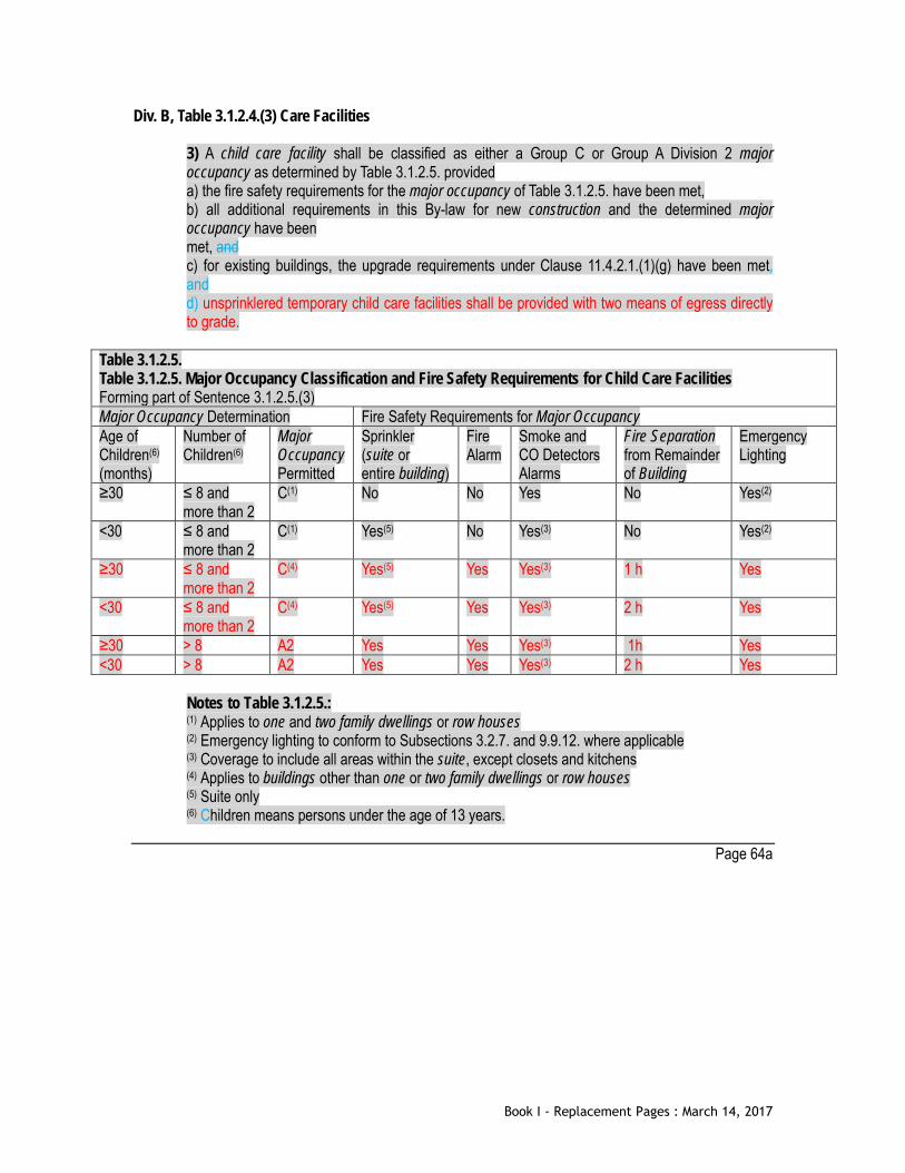
3) A child care facility shall be classified as either a Group C or Group A Division 2 major occupancy as determined by Table 3.1.2.5. provided a) the fire safety requirements for the major occupancy of Table 3.1.2.5. have been met, b) all additional requirements in this By-law for new construction and the determined major occupancy have been met, and c) for existing buildings, the upgrade requirements under Clause 11.4.2.1.(1)(g) have been met, and d) unsprinklered temporary child care facilities shall be provided with two means of egress directly to grade.
Table 3.1.2.5. Table 3.1.2.5. Major Occupancy Classification and Fire Safety Requirements for Child Care Facilities Forming part of Sentence 3.1.2.5.(3) Major Occupancy Determination Fire Safety Requirements for Major Occupancy Age of Children(6) (months)
Number of Children(6)
Major Occupancy Permitted
Sprinkler (suite or entire building)
Fire Alarm
Smoke and CO Detectors Alarms
Fire Separation from Remainder of Building
Emergency Lighting
≥30 ≤ 8 and more than 2
C(1) No No Yes No Yes(2)
<30 ≤ 8 and more than 2
C(1) Yes(5) No Yes(3) No Yes(2)
≥30 ≤ 8 and more than 2
C(4) Yes(5) Yes Yes(3) 1 h Yes
<30 ≤ 8 and more than 2
C(4) Yes(5) Yes Yes(3) 2 h Yes
≥30 > 8 A2 Yes Yes Yes(3) 1h Yes <30 > 8 A2 Yes Yes Yes(3) 2 h Yes
Notes to Table 3.1.2.5.: (1) Applies to one and two family dwellings or row houses (2) Emergency lighting to conform to Subsections 3.2.7. and 9.9.12. where applicable (3) Coverage to include all areas within the suite, except closets and kitchens (4) Applies to buildings other than one or two family dwellings or row houses (5) Suite only (6) Children means persons under the age of 13 years.
Page 64a
Book I - Replacement Pages : March 14, 2017

[This page intentionally left blank]
Book I - Replacement Pages : March 14, 2017
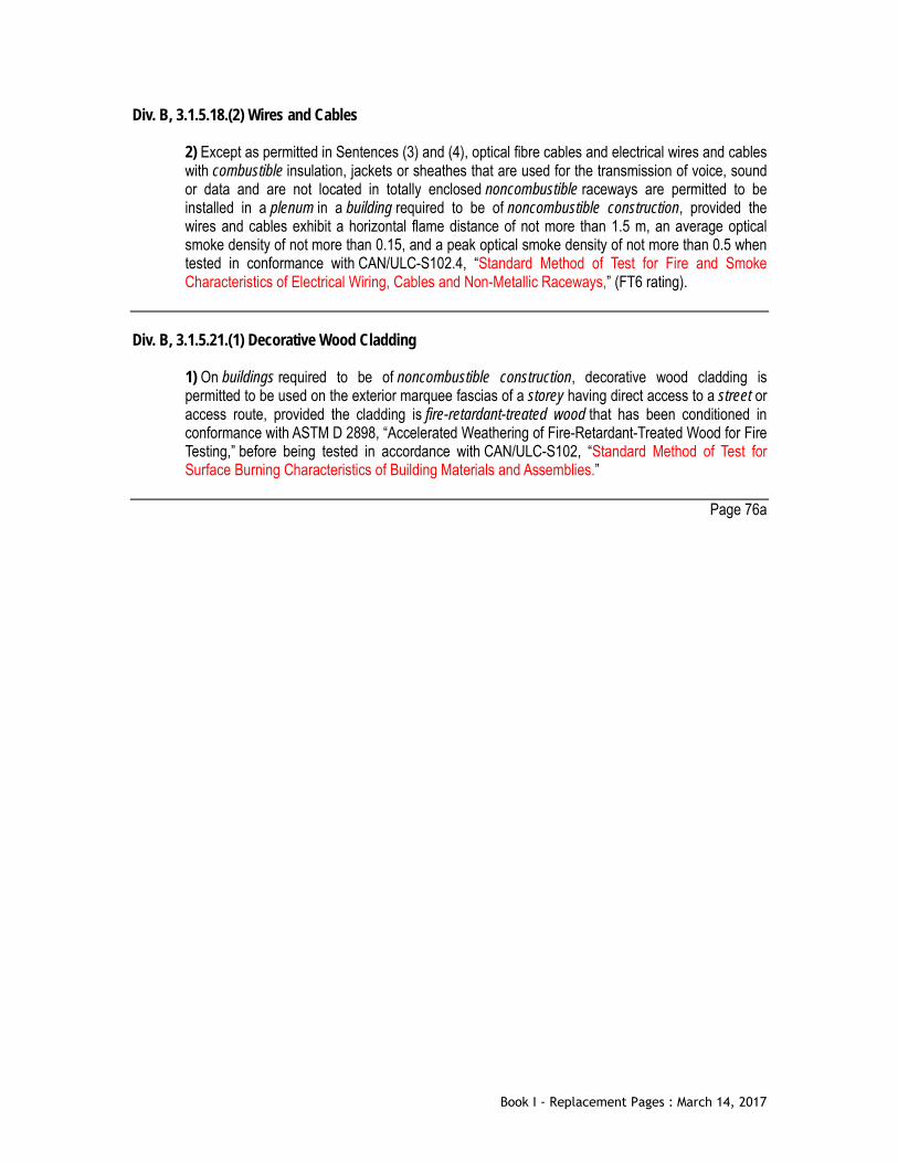
Div. B, 3.1.5.18.(2) Wires and Cables
2) Except as permitted in Sentences (3) and (4), optical fibre cables and electrical wires and cables with combustible insulation, jackets or sheathes that are used for the transmission of voice, sound or data and are not located in totally enclosed noncombustible raceways are permitted to be installed in a plenum in a building required to be of noncombustible construction, provided the wires and cables exhibit a horizontal flame distance of not more than 1.5 m, an average optical smoke density of not more than 0.15, and a peak optical smoke density of not more than 0.5 when tested in conformance with CAN/ULC-S102.4, “Standard Method of Test for Fire and Smoke Characteristics of Electrical Wiring, Cables and Non-Metallic Raceways,” (FT6 rating).
Div. B, 3.1.5.21.(1) Decorative Wood Cladding
1) On buildings required to be of noncombustible construction, decorative wood cladding is permitted to be used on the exterior marquee fascias of a storey having direct access to a street or access route, provided the cladding is fire-retardant-treated wood that has been conditioned in conformance with ASTM D 2898, “Accelerated Weathering of Fire-Retardant-Treated Wood for Fire Testing,” before being tested in accordance with CAN/ULC-S102, “Standard Method of Test for Surface Burning Characteristics of Building Materials and Assemblies.”
Page 76a
Book I - Replacement Pages : March 14, 2017

[This page intentionally left blank]
Book I - Replacement Pages : March 14, 2017

[This page intentionally left blank]
Book I - Replacement Pages : March 14, 2017

Div. B, 3.1.8.4.(1)(c) Determination of Ratings
c) CAN/ULC-S112, “Fire Test of Fire-Damper Assemblies.” Page 78b
Book I - Replacement Pages : March 14, 2017

[This page intentionally left blank]
Book I - Replacement Pages : March 14, 2017

Div. B, 3.1.12.1.(1) Determination of Ratings
1) Except as required by Sentence (2) and as permitted by Sentence (3), the flame-spread rating and smoke developed classification of a material, assembly, or structural member shall be determined on the basis of not less than three tests conducted in conformance with CAN/ULC-S102, “Standard Method of Test for Surface Burning Characteristics of Building Materials and Assemblies.”
Page 86b
Book I - Replacement Pages : March 14, 2017

[This page intentionally left blank]
Book I - Replacement Pages : March 14, 2017
Div. B, 3.2.1.1.(1) Exceptions in Determining Building Height
1) A roof-top enclosure shall not be considered as a storey in calculating the building height if the roof-top enclosure is a) provided for elevator machinery, a stairway or a service room, and b) used for no purpose other than for service to the building.
Div. B, 3.2.1.1.(3) Exceptions in Determining Building Height
3) Except as required by Sentence (5), a mezzanine need not be considered as a storey in calculating the building height, provided a) not less than 60 per cent of the horizontal plane separating the mezzanine from the room or floor space in which it is located is open, and b) except as permitted in Sentences (7) and 3.3.2.12.(3), the space above the mezzanine is used as an visually open area without partitions or subdividing walls higher than 1 070 mm above the mezzanine floor. (See Appendix A)
Page 92b
Book I - Replacement Pages : March 14, 2017

[This page intentionally left blank]
Book I - Replacement Pages : March 14, 2017
Div. B, 3.2.2.50.(3)(b) Group C, up to 6 Storeys, Sprinklered
3) Except as required in Sentence (4), a building referred to in Subclause (1) (d)(v) or (d)(vi) shall have an exterior wall assembly a) protected by noncombustible cladding b) protected by cladding of fire-retardant-treated wood that has been conditioned in conformance with ASTM D 2898, “Accelerated Weathering of Fire-Retardant-Treated Wood for Fire Testing,” before being tested in accordance with CAN/ULC-S102, “Standard Method of Test for Surface Burning Characteristics of Building Materials and Assemblies,” or c) the interior surfaces of which are protected by a thermal barrier conforming to Sentence 3.1.5.12.(3) and that satisfies the criteria of Sentences 3.1.5.5.(3) and (4) when subjected to testing in conformance with CAN/ULC-S134, “Fire Test of Exterior Wall Assemblies.”
Page 106b
Book I - Replacement Pages : March 14, 2017

[This page intentionally left blank]
Book I - Replacement Pages : March 14, 2017

Div. B, 3.2.3.13.(2) Protection of Exit Facilities
2) If any unenclosed exterior single means of egress could be exposed to fire from an opening in the exterior wall of the building it serves, the opening in the exterior wall of the building shall be protected in conformance with the requirements of Sentence (4) where the opening in the exterior wall of the building is within 3 m horizontally and a) less than 10 m below the exit stair or ramp, or b) less than 5 m above the exit stair or ramp.
Div. B, 3.2.3.13.(5)(f) Protection of Exit Facilities
5) A sprinkler water curtain for opening protection as permitted in Clause (4)(d) shall a) have quick response upright or pendant type sprinklers, b) if the opening is 1.8 m or less in width, have one sprinkler head installed at the center of the opening at a maximum distance of not more than 0.9 m from the vertical edge of the opening, c) if the opening is more than 1.8 m in width, have multiple sprinkler heads installed at a maximum distance of 1.8 m on center and at a maximum distance of not more than 0.9 m from the sprinklers to the vertical edge of the opening, d) have sprinklers located between150 mm and 300 mm horizontally from the interior face of the opening at ceiling level and not more than 3.6 m vertically above the floor immediately below, e) discharge water at a minimum flow rate of 68L/min (18 usgpm), f) have sprinkler heads with an orifice size of 12.7 mm and a k factor of nominal 5.7, g) be designed independently from the floor area coverage and be included in the most hydraulically demanding area for the design of the adjacent floor area sprinklers, h) have sprinkler heads protected from spray and from cold solder effects from adjacent sprinklers (floor area or water curtain sprinkler heads) by means of baffles in accordance with NFPA 13, and i) be provided with tempered or laminated safety glass glazed openings where windows are provided.
Page 132b
Book I - Replacement Pages : March 14, 2017

[This page intentionally left blank]
Book I - Replacement Pages : March 14, 2017

Div. B, 3.2.4.1.(1) Determination of Requirements for a Fire Alarm System
1) Except as permitted in Sentences (2), (3), (5), (6) and (7), a fire alarm system shall be installed in buildings in which an automatic sprinkler system is required by this Part.
Div. B, 3.2.4.1.(4) Determination of Requirements for a Fire Alarm System
4) Except as permitted by Sentences (5) to (7) and Sentence 3.2.4.2.(4), a fire alarm system shall be installed in a building that is not sprinklered throughout and that contains a) a contained use area, b) an impeded egress zone, c) more than 3 storeys, including the storeys below the first storey, d) a total occupant load more than 300, other than in open air seating areas, e) an occupant load more than 150 above or below the first storey, other than in open air seating areas, f) a school, college, or child care facility, including a child care facility with an occupant load more than 40, g) a licensed beverage establishment or a licensed restaurant, with an occupant load more than 150, h) a medium-hazard industrial occupancy or a low-hazard industrial occupancy with an occupant load more than 75 above or below the first storey, i) a residential occupancy with sleeping accommodation for more than 10 persons, j) a high-hazard industrial occupancy with an occupant load more than 25, or k) an occupant load more than 300 below an open air seating area.
Page 134b
Book I - Replacement Pages : March 14, 2017

[This page intentionally left blank]
Book I - Replacement Pages : March 14, 2017

Div. B, 3.2.4.9.(2) Annunciator and Zone Indication 2) Except as permitted by Sentences (6), (8), (9) and (10), the annunciator required by Sentence (1) shall have separate zone indication of the actuation of the alarm initiating devices, smoke detectors, heat detectors, manual stations and waterflow detecting devices, in each a) floor area so that the area of coverage for each zone in a building that is not sprinklered is not more than 2 000 m2, b) floor area so that the area of coverage for each zone is neither i) more than one storey, nor ii) more than the system area limits specified in NFPA 13, “Installation of Sprinkler Systems,” c) shaft required to be equipped with smoke detectors, d) air-handling system required to be equipped with smoke detectors, e) <fire extinguishing system required by NFPA 96, “Ventilation Control and Fire Protection of Commercial Cooking Operations,”> f) contained use area, g) impeded egress zone, h) fire compartment required by Sentence 3.3.3.5.(2), and i) floor area required to be equipped with smoke detector or detectors as required by Clause 3.2.4.12.(1)(h) to i) initiate an alert signal in a 2 stage system or an alarm signal in a single stage system, and ii) indicate the actuation of each device separately on the fire alarm system annunciator. Page 136b
Book I - Replacement Pages : March 14, 2017

[This page intentionally left blank]
Book I - Replacement Pages : March 14, 2017

Div. B, 3.2.4.21.(1) Smoke Alarms
1) Except as required by Sentence (4) and permitted by Sentence (7), smoke alarms conforming to CAN/ULC-S531, “Standard for Smoke-Alarms,” shall be installed in each dwelling unit and, except for care, treatment or detention occupancies required to have a fire alarm system, in each sleeping room not within a dwelling unit or suite of care occupancy.
Page 142b
Book I - Replacement Pages : March 14, 2017

[This page intentionally left blank]
Book I - Replacement Pages : March 14, 2017

Div. B, 3.2.5.5.(3) Location of Access Routes and Paths of Travel
3) Paths of travel for firefighters shall not be more than a) 45 m from the access route to the entrance door of each dwelling unit for sprinklered buildings of residential occupancy if there is no dwelling unit located above another dwelling unit, b) 55 m from the access route to the entrance door of each dwelling unit, where the dwelling unit may contain a secondary suite or lock-off unit, or the dwelling unit has no more than one dwelling unit on top, if
i) the building is sprinklered to NFPA 13R, or 13, ii) a minimum 2 m wide unobstructed access path is available for firefighters, iii) a strobe light is installed outside the principal entrance of the dwelling unit, and is connected to an internal smoke alarm within the dwelling unit, iv) sprinkler systems are monitored by the fire alarm system and by an off-site monitoring service, v) an exterior audible signal activated by the fire alarm system provides a minimum sound level of 75 db in the sleeping area of the dwelling unit, vi) emergency lighting is provided along the path of travel for firefighters, and vii) the fire alarm system has a graphic annunciator,
c) 65 m from the access route to the entrance door of each dwelling unit, where the dwelling unit may contain a secondary suite or the dwelling unit has not more than one dwelling unit on top, if
i) the requirements of Subclauses (b)(i) to (b)(vii) are met, ii) a 64 mm diameter fire department hose connection is located adjacent to the path of travel for firefighters located not more than 45 m measured from the hose connection to the principal entrance of each of the dwelling units, iii) the location of the fire department hose connections required by Subclause (c)(ii) is indicated on the fire alarm system graphic annunciator, and iv) the building is sprinklered to NFPA 13, and
d) 45 m from the access route to the entrance door, for non-residential portions of a building, which are cut off from and have no internal access to the remainder of the building.
(See Appendix A.) Page 144b
Book I - Replacement Pages : March 14, 2017

[This page intentionally left blank]
Book I - Replacement Pages : March 14, 2017

Div. B, 3.2.5.9. Standpipe System Design [Revise section as follows] 3.2.5.9. Standpipe System Design
1) Except as required or permitted by Sentences (2) to (8) and Articles 3.2.5.10. and 3.2.5.11. and Sentence 3.2.4.10.(2), the design, construction, installation and testing of a standpipe system shall conform to NFPA 14, “Installation of Standpipe and Hose Systems.” 2) A dry standpipe that is not connected to a water supply shall not be considered as fulfilling the requirements of this Article. 3) If more than one standpipe is provided, the total water supply need not be more than 30 L/s. 4) A standpipe need not be installed in a storage garage conforming to Article 3.2.2.88. provided the building is not more than 15 m high. 5) The residual water pressure at the design flow rate at the topmost hose connection of a standpipe system that is required to be installed in a building is permitted to be less than 690 kPa provided a) the building is sprinklered throughout, b) the water supply at the base of the sprinkler riser is capable of meeting, without a fire pump, the design flow rate and pressure demand of the sprinkler system, including the inside and outside hose allowance, and c) fire protection equipment is available to deliver, by means of the fire department connection, the full demand flow rate at a residual water pressure of 690 kPa at the topmost hose connection of the standpipe system. (See Appendix A.) 6) A fire department connection shall be provided for every standpipe system. 7) If a standpipe system is required by Sentence 3.2.5.8.(1) and an exit stair shaft is not provided in the building, a standpipe system may be omitted if a) a 64 mm diameter fire department hose connection is located adjacent to the path of travel for firefighters and is connected to a fire department connection in conformance with 3.2.5.15., and b) the hose connection shall be available to reach all portions of the area with 30 m of hose plus 9 m of hose stream distance. 8) A standpipe system may be omitted from dwelling units where a) the building is of residential occupancy throughout, b) the path of travel may not exceed 15 m from the principal entrance of suite to the fire department access route, c) egress from each suite complies with Sentence 3.3.4.4.(3)., and d) the travel distance from any point on the floor area to the primary entrance of each suite does not exceed 30 m.
Page 146b
Book I - Replacement Pages : March 14, 2017
Div. B, 3.2.5.12.(3) Automatic Sprinkler Systems
3) Instead of the requirements of Sentence (1), NFPA 13D, “Installation of Sprinkler Systems in One- and Two-Family Dwellings and Manufactured Homes,” is permitted to be used for the design, construction, installation and testing of an automatic sprinkler system installed a) in a building of residential occupancy throughout containing a one family dwelling or two family dwelling with or without secondary suites, where
i) each dwelling unit and its respective secondary suite has its own sprinkler water supply, and ii) a one tank-type water closet is supplied with water from the sprinkler head which is located farthest from the main water supply; or
b) in a building of care occupancy, provided i) it contains not more than 2 suites of care occupancy, ii) it has not more than 5 residents throughout, and iii) a 30-minute water supply demand can be met; or
c) in a building of residential occupancy throughout that contains only row housing where i) there is no dwelling unit located above another dwelling unit, ii) all vertical suite separations are constructed as a fire separation having no less than a 1 h fire‑resistance rating, iii) the fire separation described in Subclause (c)(ii) provides continuous protection from the top of the footing to the underside of the roof deck and any space between the top of the wall and the roof deck is tightly fitted with mineral wool or noncombustible material, iv) each row house has access to two open sides, v) each dwelling unit has its own sprinkler water supply, and vi) one tank-type water closet is supplied with water from the sprinkler head which is located farthest from the main water supply; or
d) in a laneway house where i) each bathroom, clothes closet, linen closet, and pantry must have sprinkler coverage, notwithstanding the exemptions set out in NFPA 13D, and ii) a one tank-type water closet is supplied with water from the sprinkler head which is located farthest from the main water supply.
Page 148a
Book I - Replacement Pages : March 14, 2017

Div. B, 3.2.5.12.(11) Automatic Sprinkler Systems
11) Notwithstanding the requirements of the standards referenced by Sentence (3) regarding the installation of automatic sprinkler systems, sprinklers shall be provided in any storage garage attached to a building of residential occupancy where a fire separation is not provided between the storage garage and adjacent floor areas.
Page 148b
Book I - Replacement Pages : March 14, 2017
Div. B, 3.2.5.15. Fire Department Connections 3.2.5.15. Fire Department Connections (see Appendix A)
1) The fire department connection for a standpipe system shall be located horizontally within 5 m of the principal entrance of a building, have unobstructed access and be visible from the street. 2) The fire department connection for an automatic sprinkler system shall be located horizontally within 5 m of the principal entrance of a, have unobstructed access and be visible from the street.
Page 150a
Book I - Replacement Pages : March 14, 2017

[This page intentionally left blank]
Book I - Replacement Pages : March 14, 2017

[This page intentionally left blank]
Book I - Replacement Pages : March 14, 2017

Div. B, 3.2.7.3.(1) Emergency Lighting
1) Emergency lighting shall be provided to an average level of illumination not less than 10 lx at floor or tread level in a) exits, b) principal routes providing access to exit in open floor areas and in service rooms, c) corridors used by the public, d) corridors serving sleeping rooms in a treatment occupancy, e) corridors serving sleeping rooms in a care occupancy, except corridors serving sleeping rooms within individual suites of care occupancy, f) corridors serving classrooms, g) underground walkways, h) public corridors, i) floor areas or parts thereof where the public may congregate i) in Group A, Division 1 occupancies, or
ii) in Group A, Division 2 and 3 occupancies having an occupant load of 60 or more, j) floor areas or parts thereof where persons are cared for that are within daycare facilities, including child care facilities, and k) food preparation areas in commercial kitchens.
Page 152b
Book I - Replacement Pages : March 14, 2017

[This page intentionally left blank]
Book I - Replacement Pages : March 14, 2017

Div. B, 3.2.7.10.(1) Protection of Electrical Conductors
1) Electrical conductors in buildings required to conform to Subsection 3.2.6. or Sentence 3.2.7.9.(1), shall be protected against exposure to fire, for a period of no less than 1 h, from the source of the emergency power supply to the branch circuits serving equipment, if the electrical conductors serve a) fire alarm systems, b) voice communication systems, c) the operation of an elevator referred to in Sentence 3.2.6.5.(1), d) emergency lighting referred to in Articles 3.2.7.3. and 3.2.7.4., except where self-contained emergency lighting units described in Sentence 3.2.7.4.(2) are utilized and remote lamps are located within the same floor area, and e) electrical equipment required by Clauses 3.2.7.9.(1)(b) to 3.2.7.9.(1)(e). (See Appendix A)
Page 154b
Book I - Replacement Pages : March 14, 2017

[This page intentionally left blank]
Book I - Replacement Pages : March 14, 2017

Div. B, 3.3.1.1.(5) Separation of Suites
5) Each suite other than a residential suite, located at ground level and having direct access to the street shall be separated from adjoining suites and from the remainder of the building by a fire separation having a fire-resistance rating not less than 2 h.
Page 156b
Book I - Replacement Pages : March 14, 2017

[This page intentionally left blank]
Book I - Replacement Pages : March 14, 2017

Div. B, 3.3.1.19.(8) Transparent Doors and Panels
8) An openable window which has a width greater than 380 mm, is located less than 1070 mm above interior floor level, and which opens to a space more than 600 mm below the level of the interior floor, shall be protected by a) an opening mechanism that limits the unobstructed opening to no more than 100 mm measured either vertically or horizontally, or b) a guard in conformance with Article 3.3.1.18.
Page 162b
Book I - Replacement Pages : March 14, 2017

Div. B, 3.3.2.7.(1) Doors
1) A door equipped with a latching mechanism in an access to exit from a room or suite of assembly occupancy containing an occupant load more than 100 shall be equipped with a device that will release the latch and allow the door to swing wide open when a force not more than that specified in Clause 3.3.1.13.(10)(d) is applied to the device in the direction of travel to the exit.
Page 166a
Book I - Replacement Pages : March 14, 2017

[This page intentionally left blank]
Book I - Replacement Pages : March 14, 2017
Div. B, 3.3.4.2.(1) Fire Separations
1) Except as permitted by Sentences (2) and 3.2.2.9.(2), suites of residential occupancy including secondary suites and lock-off suites shall be separated from each other and the remainder of the building by a fire separation having a fire‑resistance rating not less than 1 h.
Page 170a
Book I - Replacement Pages : March 14, 2017

[This page intentionally left blank]
Book I - Replacement Pages : March 14, 2017

Div. B, 3.3.4.9.(1) Resistance to Forced Entry
1) Dwelling units shall conform to Article 9.7.2.1. and Subsection 9.7.5.
Page 172a
Book I - Replacement Pages : March 14, 2017

[This page intentionally left blank]
Book I - Replacement Pages : March 14, 2017

[This page intentionally left blank]
Book I - Replacement Pages : March 14, 2017

Div. B, 3.3.7.3.(1) Doors
1) All entrance and exterior doors to dwelling units, doors between dwelling units and attached garages, and doors which provide direct or indirect access from storage garages to dwelling units shall conform to Subsections 9.6.1 and 9.7.3.
Div. B, 3.3.7.4.(1) Sidelights to Doors
1) All sidelights to doors and all windows adjacent to doors located within 915 mm of the door locks shall conform to Sentence 9.6.1.4.(1)
Page 174b
Book I - Replacement Pages : March 14, 2017

Div. B, 3.3.7.7.(2) Security for Storage Garage
2) If access is provided from a storage garage to a stair tower or to an elevator through a vestibule, the vestibule shall be constructed
a) with closures glazed with clear wired glass in steel frames, which provide the greatest possible unobstructed view from the storage garage into the stair tower or vestibule, b) as a fire separation with a fire‑resistance rating of not less than 1 hr, c) with full or half glazed closures with a fire-protection rating of not less than 45 min between the storage garage and the vestibule and between the vestibule and the stair tower, and d) with a row of sprinkler heads running the full width of the glazing, installed on the garage side of the vestibule at a spacing of 1800 mm on centre parallel to the glass, located between 150 mm to 300 mm perpendicular to the glazing and vertically installed on the garage ceiling in conformance with NFPA requirements.
(see Appendix A.)
Page 176a
Book I - Replacement Pages : March 14, 2017

[This page intentionally left blank]
Book I - Replacement Pages : March 14, 2017

[This page intentionally left blank]
Book I - Replacement Pages : March 14, 2017

Div. B, 3.4.6.8.(11) Treads and Risers
11) Stairs shall be provided with tactile warning strips conforming to Article 3.8.3.11. unless the stairs are a) stairs within or serving dwelling units, b) exit stairs not normally used for access purposes, or c) fire escape stairs.
Page 186b
Book I - Replacement Pages : March 14, 2017
Div. B, 3.6.5.1.(1) Duct Material
1) Except as permitted by Sentences (2) to (5) and Article 3.6.4.3., all ducts, duct connectors, associated fittings and plenums used in air duct systems shall be constructed of steel, aluminum alloy, copper, clay, asbestos-cement or other noncombustible material.
Page 198a
Book I - Replacement Pages : March 14, 2017

[This page intentionally left blank]
Book I - Replacement Pages : March 14, 2017

[This page intentionally left blank]
Book I - Replacement Pages : March 14, 2017

Div. B, 3.7.2.2.(7) Water Closets
7) The number of water closets required for primary schools and child care facilities shall be at least one for each 30 males and one for each 25 females.
Page 200b
Book I - Replacement Pages : March 14, 2017

[This page intentionally left blank]
Book I - Replacement Pages : March 14, 2017

Div. B, 3.8.3.5.(4) Main Entrances
4) Power operation that functions for passage in both directions shall be provided for all doors in an accessible path of travel at the exterior accessible entrances to a) a hotel, b) a Group B, Division 2 major occupancy, c) a Group B, Division 3 major occupancy, and d) any of the following that is more than 5OO m2 in area: i) an assembly occupancy, ii) a business and personal services occupancy, and iii) a mercantile occupancy.
Page 214b
Book I - Replacement Pages : March 14, 2017

Div. B, 3.8.3.10.(1) Floor Levels
1) Except for floors and levels specifically excluded in Subsection 3.8.2., floors and levels at different elevations shall be connected by a) a ramp conforming to Article 3.8.3.3., b) an elevator conforming to Appendix E of CAN/CSA B44, “ASME A17.1/CSA B44, “Safety Code for Elevators and Escalators,” c) an elevating device for persons with disabilities conforming to CAN/CSA-B355, “Lifts for Persons with Physical Disabilities,” or d) other means acceptable to the Chief Building Official.
Page 216a
Book I - Replacement Pages : March 14, 2017

[This page intentionally left blank]
Book I - Replacement Pages : March 14, 2017

Div. B, 3.8.5.1.(3) Application
3) This Subsection does not apply to existing buildings except for spaces created by a) an addition, b) the reconstruction of an existing space, and c) the conversion of an existing space into a secondary suite or lock-off unit.
Page 220a
Book I - Replacement Pages : March 14, 2017

[This page intentionally left blank]
Book I - Replacement Pages : March 14, 2017
Div. B, 4.3.6.1.(1) Design Basis for Glass
1) Glass used in buildings shall be designed in conformance with a) CAN/CGSB-12.20-M, “Structural Design of Glass for Buildings,” or b) ASTM E1300, “Standard Practice for Determining Load Resistance of Glass in Buildings.”
Div. B, 4.4.1.1.(1) Design Basis for Air-Supported Structures
1) The structural design of air-supported structures shall conform to CSA S367, “Air-, Cable-, and Frame-Supported Membrane Structures,” using the loads stipulated in Section 4.1., in accordance with limit states design in Subsection 4.1.3.
Page 262a
Book I - Replacement Pages : March 14, 2017

[This page intentionally left blank]
Book I - Replacement Pages : March 14, 2017

[This page intentionally left blank]
Book I - Replacement Pages : March 14, 2017
Div. B, 5.1.2.2.(1) Building Envelope Professional Requirements
1) The Building Envelope Professional shall conduct reviews, and provide letters as required in Sentences (2) and (3), on buildings or portions of buildings with a cladding system over wood framing or light steel framing and on all residential buildings within the scope of Part 5 with respect to Section 5.4, 5.5, and 5.6. (See Appendix A.)
Page 266b
Book I - Replacement Pages : March 14, 2017

Div. B, Table 5.10.1.1. [Instruction: Replace Table 5.10.1.1. with the following]
Table 5.10.1.1. Standards Applicable to Environmental Separators and Assemblies Exposed to the Exterior
Forming part of Sentence 5.10.1.1.(1) Issuing Agency Document Number Title of Document
ANSI A208.1 Particleboard ASME B18.6.1 Wood Screws (Inch Series) ASTM A 123/A 123M Zinc (Hot-Dip Galvanized) Coatings on Iron and Steel Products ASTM A 153/A 153M Zinc Coating (Hot-Dip) on Iron and Steel Hardware ASTM A 653/A 653M Steel Sheet, Zinc-Coated (Galvanized) or Zinc-Iron Alloy Coated (Galvannealed)
by the Hot-Dip Process ASTM C 4 Clay Drain Tile and Perforated Clay Drain Tile ASTM C 73 Calcium Silicate Brick (Sand-Lime Brick) ASTM C 126 Ceramic Glazed Structural Clay Facing Tile, Facing Brick, and Solid Masonry Units ASTM C 212 Structural Clay Facing Tile ASTM C 412M Concrete Drain Tile (Metric) ASTM C 444M Perforated Concrete Pipe (Metric) ASTM C 553 Mineral Fiber Blanket Thermal Insulation for Commercial and Industrial
Applications ASTM C 612 Mineral Fiber Block and Board Thermal Insulation ASTM C 700 Standard Specification for Vitrified Clay Pipe, Extra Strength, Standard Strength
and Perforated ASTM C 834(1) Latex Sealants ASTM C 920(1) Elastomeric Joint Sealants ASTM C 991 Flexible Fibrous Glass Insulation for Metal Buildings ASTM C 1002 Steel Self-Piercing Tapping Screws for the Application of Gypsum Panel Products
or Metal Plaster Bases to Wood Studs or Steel Studs ASTM C 1177/C 1177M Glass Mat Gypsum Substrate for Use as Sheathing ASTM C 1178/C 1178M Coated Glass Mat Water-Resistant Gypsum Backing Panel ASTM C 1184(1) Structural Silicone Sealants ASTM C 1311(1) Solvent Release Sealants ASTM C 1330(1) Cylindrical Sealant Backing for Use with Cold Liquid Applied Sealants ASTM C 1396/C 1396M Gypsum Board ASTM D 2178 Asphalt Glass Felt Used in Roofing and Waterproofing ASTM E 2190 Insulating Glass Unit Performance and Evaluation AWPA M4 Care of Preservative-Treated Wood Products BNQ BNQ 3624-115 Polyethylene (PE) Pipe and Fittings – Flexible Pipes for Drainage – Characteristics
and Test Methods CGSB CAN/CGSB-11.3-M Hardboard CGSB CAN/CGSB-11.5-M Hardboard, Precoated, Factory Finished, for Exterior Cladding CGSB CAN/CGSB-12.1-M Tempered or Laminated Safety Glass CGSB CAN/CGSB-12.2-M Flat, Clear Sheet Glass CGSB CAN/CGSB-12.3-M Flat, Clear Float Glass CGSB CAN/CGSB-12.4-M Heat Absorbing Glass CGSB CAN/CGSB-12.8 Insulating Glass Units CGSB CAN/CGSB-12.10-M Glass, Light and Heat Reflecting
Book I - Replacement Pages : March 14, 2017

CGSB CAN/CGSB-12.11-M Wired Safety Glass CGSB CAN/CGSB-34.22 Asbestos-Cement Drain Pipe CGSB CAN/CGSB-37.1-M Chemical Emulsifier Type, Emulsified Asphalt for Dampproofing CGSB CAN/CGSB-37.2-M Emulsified Asphalt, Mineral-Colloid Type, Unfilled, for Dampproofing and
Waterproofing and for Roof Coatings CGSB CAN/CGSB-37.3-M Application of Emulsified Asphalts for Dampproofing or Waterproofing CGSB CAN/CGSB-37.4-M Fibrated, Cutback Asphalt, Lap Cement for Asphalt Roofing CGSB CAN/CGSB-37.5-M Cutback Asphalt Plastic, Cement CGSB 37-GP-6Ma Asphalt, Cutback, Unfilled, for Dampproofing CGSB CAN/CGSB-37.8-M Asphalt, Cutback, Filled, for Roof Coating CGSB 37-GP-9Ma Primer, Asphalt, Unfilled, for Asphalt Roofing, Dampproofing and Waterproofing CGSB 37-GP-12Ma Application of Unfilled Cutback Asphalt for Dampproofing CGSB CAN/CGSB-37.16-M Filled, Cutback Asphalt for Dampproofing and Waterproofing CGSB 37-GP-18Ma Tar, Cutback, Unfilled, for Dampproofing CGSB 37-GP-21M Tar, Cutback, Fibrated, for Roof Coating CGSB CAN/CGSB-37.22-M Application of Unfilled, Cutback Tar Foundation Coating for Dampproofing CGSB 37-GP-36M Application of Filled Cutback Asphalts for Dampproofing and Waterproofing CGSB 37-GP-37M Application of Hot Asphalt for Dampproofing or Waterproofing CGSB CAN/CGSB-37.50-M Hot-Applied, Rubberized Asphalt for Roofing and Waterproofing CGSB CAN/CGSB-37.51-M Application for Hot-Applied Rubberized Asphalt for Roofing and Waterproofing CGSB 37-GP-52M Roofing and Waterproofing Membrane, Sheet Applied, Elastomeric CGSB CAN/CGSB-37.54 Polyvinyl Chloride Roofing and Waterproofing Membrane CGSB 37-GP-55M Application of Sheet Applied Flexible Polyvinyl Chloride Roofing Membrane CGSB 37-GP-56M Membrane, Modified, Bituminous, Prefabricated, and Reinforced for Roofing CGSB 37-GP-64M Mat Reinforcing, Fibrous Glass, for Membrane Waterproofing Systems and Built-
Up Roofing CGSB 41-GP-6M Sheets, Thermosetting Polyester Plastics, Glass Fiber Reinforced CGSB CAN/CGSB-41.24 Rigid Vinyl Siding, Soffits and Fascia CGSB CAN/CGSB-51.32-M Sheathing, Membrane, Breather Type CGSB CAN/CGSB-51.33-M Vapour Barrier Sheet, Excluding Polyethylene, for Use in Building Construction CGSB CAN/CGSB-51.34-M Vapour Barrier, Polyethylene Sheet for Use in Building Construction CGSB CAN/CGSB-93.1-M Sheet, Aluminum Alloy, Prefinished, Residential CGSB CAN/CGSB-93.2-M Prefinished Aluminum Siding, Soffits and Fascia, for Residential Use CGSB CAN/CGSB-93.3-M Prefinished Galvanized and Aluminum-Zinc Alloy Steel Sheet for Residential Use CGSB CAN/CGSB-93.4 Galvanized Steel and Aluminum-Zinc Alloy Coated Steel Siding, Soffits and Fascia,
Prefinished, Residential CSA A23.1 Concrete Materials and Methods of Concrete Construction CSA CAN/CSA-A82.1-M Burned Clay Brick (Solid Masonry Units Made from Clay or Shale) CSA A82.4-M Structural Clay Load-Bearing Wall Tile CSA A82.5-M Structural Clay Non-Load-Bearing Tile CSA CAN3-A82.8-M Hollow Clay Brick CSA CAN/CSA-A82.27-M Gypsum Board CSA A82.30-M Interior Furring, Lathing and Gypsum Plastering CSA A82.31-M Gypsum Board Application CSA CAN3-A93-M Natural Airflow Ventilators for Buildings CSA A123.1/A123.5 Asphalt Shingles Made From Organic Felt and Surfaced with Mineral
Granules/Asphalt Shingles Made From Glass Felt and Surfaced with Mineral Granules
CSA CAN/CSA-A123.2 Asphalt-Coated Roofing Sheets
Book I - Replacement Pages : March 14, 2017

CSA A123.3 Asphalt Saturated Organic Roofing Felt CSA CAN/CSA-A123.4 Asphalt for Constructing Built-Up Roof Coverings and Waterproofing Systems CSA A123.17 Asphalt Glass Felt Used in Roofing and Waterproofing CSA CAN3-A123.51-M Asphalt Shingle Application on Roof Slopes 1:3 and Steeper CSA CAN3-A123.52-M Asphalt Shingle Application on Roof Slopes 1:6 to Less Than 1:3 CSA CAN/CSA-A165.1 Concrete Block Masonry Units CSA CAN/CSA-A165.2 Concrete Brick Masonry Units CSA CAN/CSA-A165.3 Prefaced Concrete Masonry Units CSA CAN3-A165.4-M Autoclaved Cellular Units CSA CAN/CSA A179 Mortar and Grout for Unit Masonry CSA CAN/CSA-A220 Series Concrete Roof Tiles CSA CAN/CSA A371 Masonry Construction for Buildings CSA CAN/CSA-A3001 Cementitious Materials for Use in Concrete CSA CAN/CSA-B182.1 Plastic Drain and Sewer Pipe and Pipe Fittings CSA CAN/CSA-G40.21 General Requirements for Rolled or Welded Structural Quality Steel CSA CAN/CSA-G401 Corrugated Steel Pipe Products CSA CAN/CSA-O80 Series Wood Preservation CSA O115-M Hardwood and Decorative Plywood CSA O118.1 Western Red Cedar Shakes and Shingles CSA O118.2 Eastern White Cedar Shingles CSA O121 Douglas Fir Plywood CSA CAN/CSA-O141 Softwood Lumber CSA O151 Canadian Softwood Plywood CSA O153-M Poplar Plywood CSA CAN/CSA-O325 Construction Sheathing CSA O437.0 OSB and Waferboard ULC CAN/ULC-S701 Thermal Insulation, Polystyrene, Boards and Pipe Covering ULC CAN/ULC-S702 Mineral Fibre Thermal Insulation for Buildings ULC CAN/ULC-S703 Cellulose Fibre Insulation (CFI) for Buildings ULC CAN/ULC-S704 Thermal Insulation, Polyurethane and Polyisocyanurate, Boards, Faced ULC CAN/ULC-S705.1 Thermal Insulation – Spray Applied Rigid Polyurethane Foam, Medium Density –
Material - Specification ULC CAN/ULC-S705.2 Thermal Insulation – Spray-Applied Rigid Polyurethane Foam, Medium Density —
Application ULC CAN/ULC-S706 Standard for Wood Fibre Thermal Insulation for Buildings
Notes to Table 5.10.1.1.:
(1) See Appendix A.
Page 274c
Book I - Replacement Pages : March 14, 2017

Div. B, Table 5.10.1.1. [Instruction: Replace Table 5.10.1.1. with the following – See over] Page 274d
Book I - Replacement Pages : March 14, 2017

[This page intentionally left blank]
Book I - Replacement Pages : March 14, 2017
Div. B, 5.10.2. Windows, Doors, Skylights and Other Glazed Products [Instruction: Replace the Subsection Headers and Articles 5.10.2.1 through 5.10.2.3.] 5.10.2. Windows, Doors, Skylights and Other Glazed Products 5.10.2.1. General
1) This Subsection applies to windows, doors, skylights, other glazed products and their components that separate a) interior space from exterior space, or b) environmentally dissimilar interior spaces. 2) For the purposes of this Subsection, the term “skylight” refers to unit skylights, roof windows and tubular daylighting devices. 3) Windows, doors, skylights, other glazed products and their components that are required to have a fire-protection rating need not conform to this Subsection. (See Appendix A.)
5.10.2.2. Design and Construction (See Appendix A.)
1) Windows, doors, skylights and their components shall be designed and constructed in accordance with a) Subsection 5.1.4., Section 5.3., Section 5.4. and Section 5.6., or b) the following standards:
i) AAMA/WDMA/CSA 101/I.S.2/A440, “NAFS – North American Fenestration Standard/Specification for Windows, Doors, and Skylights,” and ii) except as permitted by Sentence (3), CSA A440SI, “Canadian Supplement to AAMA/WDMA/CSA 101/I.S.2/A440, NAFS – North American Fenestration Standard/Specification for Windows, Doors, and Skylights.” (See Appendix A.)
2) Other glazed products and their components shall be designed and constructed in accordance with Subsection 5.1.4., Section 5.3., Section 5.4. and Section 5.6. (See Appendix A.) 3) For the purposes of conformance with Subclause (1)(b)(ii), loads and procedures from Section 5.2. may be used instead of the loads and procedures set out in the standard. (See Appendix A.)
5.10.2.3. [Reserved.] Page 278b
Book I - Replacement Pages : March 14, 2017

Div. B, 6.2.1.4.(1) Installations Standards
1) Except as provided in Articles 6.2.1.5. and 6.2.1.6., the installation of heating and air-conditioning equipment, including mechanical refrigeration equipment, and including provisions for mounting, clearances and air supply, shall conform to the requirements of a) CAN/CSA-B139, “Installation Code for Oil Burning Equipment,” for the installation of oil burning equipment, b) the BC Safety Standards Act and the following of its regulations:
i) the Gas Safety Regulation for the installation of natural gas and propane burning equipment, ii) the Electrical Safety Regulation, and iii) the Power Engineers, Boiler, Pressure Vessel and Refrigeration Safety Regulation for the installation of boilers, pressure vessels, pressure piping and mechanical refrigeration, and
c) CAN/CSA B365, “Installation Code for Solid-Fuel Burning Appliances and Equipment,” for the installation of solid fuel burning equipment.
Page 286a
Book I - Replacement Pages : March 14, 2017

[This page intentionally left blank]
Book I - Replacement Pages : March 14, 2017

Div. B, 6.2.2.6.(1) Hazardous Gases, Dusts or Liquids
1) Except as provided in Subsection 6.2.12., systems serving spaces that contain hazardous gases, dusts or liquids shall be designed, constructed and installed to conform to the requirements of the applicable provincial enactments or city by-laws or, in the absence of such enactments or bylaws, to good engineering practice such as that described in the publications of the National Fire Protection Association and in the Fire By-law. (See Appendix A.)
Div. B, 6.2.2.7. Commercial Cooking Equipment
1) Systems for the ventilation of commercial cooking equipment shall be designed, constructed and installed to conform to NFPA 96, “Ventilation Control and Fire Protection of Commercial Cooking Operations,” except as required by Sentences (3) and (4), Sentence 3.6.3.1.(1) and Article 3.6.4.2. 2) Fire protection systems for commercial cooking equipment referred to in Sentence (1) using vegetable oil or animal fat shall conform to
a) ANSI/UL 300, “Fire Testing of Fire Extinguishing Systems for Protection of Commercial Cooking Equipment,” or b) ULC/ORD-C1254.6, “Fire Testing of Restaurant Cooking Area Fire Extinguishing System Units.”
3) The exhaust from a commercial cooking unit shall discharge through an ecology unit or acceptable equipment complying with Sentence (5), where the exterior wall termination of the exhaust is within 3 m of a lane, property line or street property line. (See Appendix A.) 4) The exhaust from a commercial cooking unit which is discharged from an exterior wall termination shall not a) be discharged in a location or manner which causes a concentrated stream of air to fall directly onto pedestrians, b) be discharged in a location or manner which causes exhaust to accumulate in an area with outdoor seating, and c) generate a sound pressure level which exceeds noise levels permitted by the Noise Control By-law. (See Appendix A.) 5) Equipment provided in compliance with Sentence 6.2.2.7.(3) shall a) remove 99.97% of the grease entering the equipment, b) be of continuously welded 1.5 mm thick carbon steel or 1.1 mm stainless steel, c) prevent the leakage of flame, smoke, or grease from the equipment at normal or abnormal temperatures, d) limit the temperature rise of adjacent combustible materials to no more than 97°C above room temperature, and e) limit the temperature of exhaust air at the exhaust outlet to no more than 138°C.
Page 288a
Book I - Replacement Pages : March 14, 2017

[This page intentionally left blank]
Book I - Replacement Pages : March 14, 2017

Div. B, 6.2.3.9.(3) Interconnection of Systems
3) Exhaust ducts referred to in Sentence 6.2.3.8.(10) may exhaust through an enclosed storage garage prior to exhausting to the outdoors, provided a) the storage garage's exhaust system runs continuously, b) the capacity of the storage garage's exhaust system is equal to or exceeds the volume of the exhaust entering the garage, and c) a leakage rate 1 smoke/fire damper rated in accordance with CAN/ULC-S112.1, “Leakage Rated Dampers for Use in Smoke Control Systems,” is provided near the duct outlet location in the storage garage to prevent air from the storage garage from entering the exhaust ductwork system in the event the building's exhaust fan is shut down.
Page 290a
Book I - Replacement Pages : March 14, 2017

[This page intentionally left blank]
Book I - Replacement Pages : March 14, 2017

[This page intentionally left blank]
Book I - Replacement Pages : March 14, 2017
Div. B, 8.1.1.1. Scope
1) The scope of this Part shall be as described in Subsection 1.3.3. of Division A. 2) This Part applies to fire safety and the protection of the public during construction projects, including any incompleted or abandoned building. 3) Fire safety at project sites shall conform to the Fire By-law and Subsection 8.2.6.
Page 302b
Book I - Replacement Pages : March 14, 2017
Div. B, 8.1.3.3. Posting Requirements
1) No construction shall commence until a copy of the Construction Safety Plan which complies with this subsection is posted on the project site in accordance with Sentence (2). 2) The copy of the Construction Safety Plan required by Sentence (1) shall be
a) posted on plywood measuring not less than 600 mm by 600 mm, which is staked into the ground, protected from the weather and visible from the street, or b) posted on the exterior of the principal construction site shelter.
3) A copy of the Construction Safety Plan shall be posted on the project site at all times during construction.
Div. B, 8.1.4.1. Requirement for Construction Safety Officer
1) Where construction of a building includes the services of a Coordinating Registered Professional, a full-time Construction Safety Officer shall be present on the project site at all times during construction.
Div. B, 8.2.1.1.(2) Covered Walkways
2) Despite the provisions of Sentence (1) a covered walkway is not required on a sidewalk if a) the work is carried out entirely behind fencing, boarding or barricades which separate the construction site from the sidewalk, or b) the building is located no less than 2 m from a sidewalk used by pedestrians, except that the Chief Building Official may require a covered walkway for a site which contains a project if, in the opinion of the Chief Building Official, site conditions so warrant.
Page 304a
Book I - Replacement Pages : March 14, 2017

Div. B, 8.2.1.5.(1) Work Shutdown
1) All hazardous areas on a project site shall be secured against unauthorized entry at all times when workers are not present on the site.
Div. B, 8.2.3.1.(1) Safe Passage Past Site
1) Except as provided in Article 8.2.3.2., provision shall be made at all times for the safe passage of pedestrian and vehicular traffic past the project site.
Page 304b
Book I - Replacement Pages : March 14, 2017

Div. B, 8.2.4.1.(1) Protection of the Public on Public Ways
1) If work on a project site creates a traffic hazard on or adjacent to a public way, traffic control measures for the duration of the hazard shall include a) persons to direct construction workers, b) persons to direct vehicle and pedestrian traffic, c) appropriate warning signs indicating the presence of construction work and flagpersons. d) warning signs indicating any lane closures, e) if there is a lane closure of a vehicle travel lane, retro reflective lane control devices set up in a gradual taper to close the vehicle travel lane, f) if there is a lane closure of a vehicle travel lane at night, yellow flashing lights mounted on retro reflective barricades at the closure point of the vehicle travel lane, g) retro reflective lane control devices surrounding the closed portion of any public way, and h) at night, retro reflective barricades with yellow flashing lights in front of any construction material or equipment which is not marked with retro reflective sheeting.
Page 306a
Book I - Replacement Pages : March 14, 2017

[This page intentionally left blank]
Book I - Replacement Pages : March 14, 2017

Div. B, 8.2.6.1.(1) Application
1) This Subsection applies to fire safety for projects undergoing construction and adjacent projects. Div. B, 8.2.6.3.(1) Fire Safety Plan
1) Before the commencement of construction, a fire safety plan for the project site shall be submitted to and accepted by the Chief Building Official.
Div. B, 8.2.6.4.(5) Access for Firefighting
5) Where a project is enclosed by fencing, boarding or barricades, firefighters shall be provided with 24 hour emergency access for fire department equipment and personnel.
Page 308a
Book I - Replacement Pages : March 14, 2017

[This page intentionally left blank]
Book I - Replacement Pages : March 14, 2017

Div. B, 8.2.6.14.(2) Requirement for Fire Watch
2) A fire watch as required by Sentence (1) shall include: a) a complete tour of inspection of the project at least once every hour, b) facilities to provide a fire warning to occupants, to the satisfaction of the Chief Building Official, and c) facilities to communicate with the fire department in the event of fire, to the satisfaction of the Chief Building Official.
Div. B, 8.2.6.17.(1) Fire Warning in Buildings under Construction
1) Facilities shall be provided to alert persons on a project to the presence of a fire and such facilities shall be audible throughout the building.
Page 310a
Book I - Replacement Pages : March 14, 2017

[This page intentionally left blank]
Book I - Replacement Pages : March 14, 2017

[This page intentionally left blank]
Book I - Replacement Pages : March 14, 2017
Div. B, 9.3.1.1.(4) General
4) For flat insulating concrete form walls not exceeding 2 storeys in building height and having a maximum floor to floor height of 3 m, in buildings of light-frame construction containing only a single dwelling unit, the concrete and reinforcing shall comply with Part 4 or a) the concrete shall conform to CSA A23.1, “Concrete Materials and Methods of Concrete Construction,” with a maximum aggregate size of 19 mm, and b) the reinforcing shall
i) conform to CAN/CSA-G30.18-M, “Carbon Steel Bars for Concrete Reinforcement,” ii) have a minimum specified yield strength of 400 MPa, and iii) be lapped a minimum of 450 mm for 10M bars and 650 mm for 15M bars (See also Articles 9.15.4.5. and 9.20.17.2. to 9.20.17.4.).
Page 320b
Book I - Replacement Pages : March 14, 2017

Div. B, 9.3.1.8.(1) Admixtures
1) Admixtures shall conform to ASTM C 260/C 260M, “Air-Entraining Admixtures for Concrete,” or ASTM C 494/C 494M, “Chemical Admixtures for Concrete,” as applicable.
Page 322a
Book I - Replacement Pages : March 14, 2017
Div. B, 9.3.2.1.(1) Grade Marking
1) Lumber for joists, rafters, trusses and beams and for the uses listed in Table 9.3.2.1. shall be identified by a grade stamp to indicate its grade as determined by NLGA 2010, “Standard Grading Rules for Canadian Lumber.”(See Appendix A.)
Page 322b
Book I - Replacement Pages : March 14, 2017
Div. B, 9.4.2.1.(1) Application
1) This Subsection applies to light-frame constructions whose wall, floor and roof planes are generally comprised of frames of small repetitive structural members, and where a) the roof and wall planes are clad, sheathed or braced on at least one side, b) the small repetitive structural members are spaced not more than 600 mm o.c., c) the clear span of any structural member does not exceed 12.2 m, d) the maximum deflection of the structural roof members conforms to Article 9.4.3.1., e) the maximum total roof area, notwithstanding any separation of adjoining buildings by firewalls, is 4550 m2, and f) for flat roofs, there are no significant obstructions on the roof, such as parapet walls, spaced closer than the distance calculated by Do = 10(Ho – 0.8Ss/γ) where
Do = minimum distance between obstructions, m, Ho = height of the obstruction above the roof, m, Ss = ground snow load, kPa, and ϒ = unit weight of snow, kN/m3.
(See Appendix A.) Div. B, 9.4.2.2 Specified Snow Loads 9.4.2.2. Specified Snow Loads (see Appendix A.)
1) Except as provided in Sentences (2) and (3), specified snow loads shall be not less than those calculated using the following formula:
S = CbSs + Sr where
S = specified snow load, Cb = basic snow load roof factor, which is 0.45 where the entire width of the roof does not exceed 4.3 m and 0.55 for all other roofs, Ss = 1-in-50-year ground snow load in kPa, determined according to Subsection 1.1.3., and Sr = associated 1-in-50-year rain load in kPa, determined according to Subsection 1.1.3.
2) In no case shall the specified snow load be less than 1 kPa. 3) Bow string, arch or semi-circular roof trusses having an unsupported span greater than 6 m shall be designed in conformance with the snow load requirements in Subsection 4.1.6.
Page 326a
Book I - Replacement Pages : March 14, 2017

[This page intentionally left blank]
Book I - Replacement Pages : March 14, 2017

Div. B, 9.6.1.1.(1) Application
1) This Section applies to glass, and the protection of glass, in a) doors, including closet doors and sidelights for doors, b) windows, c) skylights as defined in Sentence 9.7.1.1.(2), d) shower or bathtub enclosures, e) glazed panels and partitions, or f) glass guards. (See Appendix A.)
Page 330a
Book I - Replacement Pages : March 14, 2017
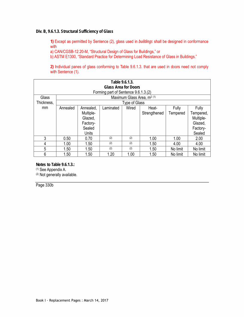
Div. B, 9.6.1.3. Structural Sufficiency of Glass
1) Except as permitted by Sentence (2), glass used in buildings shall be designed in conformance with a) CAN/CGSB-12.20-M, “Structural Design of Glass for Buildings,” or b) ASTM E1300, “Standard Practice for Determining Load Resistance of Glass in Buildings.” 2) Individual panes of glass conforming to Table 9.6.1.3. that are used in doors need not comply with Sentence (1).
Table 9.6.1.3.
Glass Area for Doors Forming part of Sentence 9.6.1.3.(2)
Glass Thickness,
mm
Maximum Glass Area, m2 (1) Type of Glass
Annealed Annealed, Multiple- Glazed, Factory-Sealed Units
Laminated Wired Heat- Strengthened
Fully Tempered
Fully Tempered, Multiple- Glazed, Factory-Sealed
3 0.50 0.70 (2) (2) 1.00 1.00 2.00 4 1.00 1.50 (2) (2) 1.50 4.00 4.00 5 1.50 1.50 (2) (2) 1.50 No limit No limit 6 1.50 1.50 1.20 1.00 1.50 No limit No limit
Notes to Table 9.6.1.3.: (1) See Appendix A. (2) Not generally available. Page 330b
Book I - Replacement Pages : March 14, 2017

Div. B, 9.7 Windows, Doors and Skylights [Replace header to Section 9.7 as follows] 9.7 Windows, Doors and Skylights (See Appendix A and A-9.7.4. in Appendix A.) Div. B, 9.7.1.1.(3) Application
3) For the purpose of this Section, the term “doors” includes glazing in doors and sidelights for doors but does not include vehicular access doors.
Div. B, 9.7.2.2. [Reserved]. [Replace 9.7.2.2. as follows.] 9.7.2.2. [Reserved]. Page XXb Div. B, 9.7.3.1. General Performance Expectations [Replace Article 9.7.3.1. as follows.]
1) [Reserved.] 2) Skylights and their components shall be designed, constructed and installed so that they resist snow loads.
Page 332a
Book I - Replacement Pages : March 14, 2017

Div. B, 9.7.3.1. General Performance Expectations [Replace Article 9.7.3.1. as follows – See over] Div. B, 9.7.3.3. Thermal Characteristics of Windows, Doors and Skylights [Replace Sentences (1) & (2) as follows]
1) Except as permitted in Sentence (2), metal frames, and metal sashes, of windows, doors and skylights shall incorporate a thermal break. 2) Windows and doors described in Sentence (1) do not require a thermal break where they a) are installed as storm windows and doors, or b) are required to have a fire-protection rating.
Div. B, 9.7.4. Manufactured Windows, Doors and Skylights [Replace the header to Subsection 9.7.4. with the following] 9.7.4. Design and Construction (See Appendix A.) Div. B, 9.7.4.1. Application [Replace Article 9.7.4.1. with the following] 9.7.4.1. General
1) Except as provided by Sentence (2), windows, doors, skylights and their components shall be designed and constructed in accordance with a) Article 9.7.4.2., or b) Part 5.
2) Windows, doors, skylights and their components that are required to have a fire-protection rating need not conform to this Subsection. (See Appendix A.)
Page 332b
Book I - Replacement Pages : March 14, 2017

Div. B, 9.7.4.2. General [Replace Subsection 9.7.4. with the following – see over.] 9.7.4.2. Standards
1) Except as permitted by Sentence (2) and Article 9.7.4.3., windows, doors, skylights and their components shall conform to a) AAMA/WDMA/CSA 101/I.S.2/A440, “NAFS – North American Fenestration Standard/Specification for Windows, Doors, and Skylights” (Harmonized Standard), and b) A440S1, “Canadian Supplement to AAMA/WDMA/CSA 101/I.S.2/A440, NAFS – North American Fenestration Standard/Specification for Windows, Doors, and Skylights.” (See Appendix A.) 2) A door designated as a “Limited Water” door in accordance with the standard referenced in Clause (1)(a) shall not be used unless the door a) separates a dwelling unit from an unconditioned storage garage or a carport, b) conforms to Clauses 3.3.1.13.(1)(a), (b) and (c) and Sentences 3.3.1.13.(5) and (10), or c) is not required by Sentence 9.27.3.8.(3) to have flashing installed.
9.7.4.3. Performance Requirements
1) For the purposes of compliance with the standard referenced in Clause 9.7.4.2.(1)(b), windows, doors and their components in a building of no more than 10 m in height, measured from grade, may conform to the design pressure, performance grade and water resistance values in Table C-4 of Appendix C instead of the values calculated in the Canadian Supplement. 2) For buildings described in Sentence 1.3.3.3.(1) of Division A, where design pressure, performance grade and water resistance values are calculated in accordance with the standard referenced in Clause 9.7.4.2.(1)(b), the driving rain wind pressure (DRWP) values in Table A.1 of CSA A440S1, “Canadian Supplement to AAMA/WDMA/CSA 101/I.S.2/A440, NAFS – North American Fenestration Standard/Specification for Windows, Doors, and Skylights,” shall be used. (See Appendix A.)
Div. B, 9.7.5. Resistance to Forced Entry [Replace the header to Subsection 9.7.5. with the following] 9.7.5. Resistance to Forced Entry Div. B, 9.7.5.1 Application and Compliance [Replace Article 9.7.5.1. as follows – see next page.] Div. B, 9.7.5.2 Resistance to Forced Entry [Replace Article 9.7.5.1. as follows – see next page.]
Page 334a
Book I - Replacement Pages : March 14, 2017

Div. B, 9.7.5.1 Application and Compliance [Replace Article 9.7.5.1. as follows] 9.7.5.1. Resistance to Forced Entry for Sliding Doors
1) This Article applies to sliding doors serving dwelling units, other than exterior doors to garages and to other ancillary spaces.
2) Sliding doors shall not permit the removal of the sliding panel when in the locked position. 3) Exterior doors shall a) have a pin type locking mechanism, with a minimum 9 mm throw into the frame, or an equivalent locking mechanism, operable from the interior without the use of keys, special devices or specialized knowledge of the locking mechanism, or b) conform to at least Grade 10 in ASTM F842, “Standard Test Methods for Measuring the Forced Entry Resistance of Sliding Door Assemblies, Excluding Glazing Impact.”
9.7.5.2. Resistance to Forced Entry for Swinging Doors [Replace Sentences (2) to (6) with the following]
2) Doors, frames and hardware that conform to AAMA 1304, “Voluntary Specification for Forced Entry Resistance of Side-Hinged Door Systems,” are not required to conform to Sentences (3) to (7). 3) Wood doors described in Sentence (1) shall a) be solid core or stile-and-rail type, b) be not less than 45 mm thick, and c) if of the stile-and-rail type, have a panel thickness of not less than 19 mm, with a total panel area not more than half of the door area. 4) Doors described in Sentence (1) shall be provided with a) a deadbolt lock with a cylinder having no fewer than 5 pins, and b) a bolt throw not less than 25 mm long, protected with a solid or hardened free-turning ring or bevelled cylinder housing. (See Article 9.9.6.7.) 5) An inactive leaf in double doors used in locations specified in Sentence (1) shall be provided with heavy-duty bolts top and bottom having an engagement of not less than 15 mm. 6) Hinges for doors described in Sentence (1) shall be fastened a) to wood doors with wood screws not less than 25 mm long and to wood frames with wood screws so that at least 2 screws per hinge penetrate not less than 30 mm into solid wood, or b) to metal doors and metal frames with machine screws not smaller than No. 10 and not less than 10 mm long.
(See Appendix A.) Page 334b
Book I - Replacement Pages : March 14, 2017

Div. B, 9.8.8.1. Required Guards
5) Except as provided in Sentence (6), openable windows in buildings of residential occupancy shall be protected by a) a guard, or b) a mechanism capable of controlling the free swinging or sliding of the openable part of the window so as to limit any clear unobstructed opening to not more than 100 mm measured either vertically or horizontally where the other dimension is greater than 380 mm. (See Appendix A.) 6) Windows need not be protected in accordance with Sentence (5), where a) the windows serve a dwelling unit that is not located above another suite, or b) Reserved. c) openings greater than 100 by 380 mm are
i) located more than 900 mm above the finished floor on one side of the window, and ii) construction below the opening does not facilitate climbing, or
d) windows are designed such that i) the only opening greater than 100 mm by 380 mm is a horizontal opening at the top of the window, ii) the opening is at least 450 mm above the window sill, and iii) the window sill is located more than 450 mm above the finished floor on one side of the window, or
e) the window is located in a room or space with the finished floor described in Clause 9.8.8.1.(6)(d) located less than 1 800 mm above the floor or ground on the other side of the window. (See A-9.8.8.1.(5) in Appendix A.)
Page 342a
Book I - Replacement Pages : March 14, 2017

Div. B, 9.8.8.1. Required Guards [Replace Sentences 9.8.8.1.(5) & (6) with the following – see over.] Page 342b
Book I - Replacement Pages : March 14, 2017
Div. B, 9.9.4.4.(1) Openings Near Unenclosed Exterior Exit Stairs and Ramps
1) Unprotected openings in exterior walls of the building shall be protected with wired glass in fixed steel frames, glass block conforming to Articles 9.10.13.5. and 9.10.13.7., or protection complying with the requirements of Sentence 3.2.3.13.(5), where a) an unenclosed exterior exit stair or ramp provides the only means of egress from a suite or secondary suite and is exposed to fire from unprotected openings in the exterior walls of
i) another fire compartment, or ii) another dwelling unit, and
b) unprotected openings in the exterior walls of the building are within 3 m horizontally and less than 10 m below or 5 m above the exit stair or ramp.
Div. B, 9.9.4.5.(1) Openings Near Unenclosed Exterior Exit Stairs and Ramps
1) Either openings in exterior walls of an exit or openings in adjacent exterior walls of the building the exit serves shall be protected with wired glass in fixed steel frames or glass block installed in accordance with Articles 9.10.13.5. and 9.10.13.7., where a) the exit enclosure has exterior walls that intersect the exterior walls of the building at an angle of less than 135° measured on the outside of the building, and b) the openings in the exterior walls of the building are within 3 m horizontally and less than 2 m above the openings in the exterior walls of the exit. (See Appendix A.) 2) The opening protection referred to in Sentence (1) may conform to Sentence 3.2.3.13.(4).
Div. B, 9.9.4.6.(1) Openings Near Exit Doors
1) Where an exterior exit door in one fire compartment is within 3 m horizontally of an unprotected opening in another fire compartment and the exterior walls of these fire compartments intersect at an exterior angle of less than 135°, the opening shall be protected with a) wired glass in fixed steel frames conforming to Article 9.10.13.5., or b) glass block conforming to Article 9.10.13.7., or
c) protection complying with the requirements of Sentence 3.2.3.13.(5). 2) The opening protection referred to in Sentence (1) may conform to Sentence 3.2.3.13.(4).
Page 348a
Book I - Replacement Pages : March 14, 2017

[This page intentionally left blank]
Book I - Replacement Pages : March 14, 2017

Div. B, 9.10.4.4.(1) Roof-Top Enclosures
1) A roof-top enclosure shall not be considered as a storey in calculating the building height if the roof-top enclosure is a) provided for elevator machinery, a stairway or a service room, and b) used for no purpose other than for service to the building.
Page 358a
Book I - Replacement Pages : March 14, 2017

[This page intentionally left blank]
Book I - Replacement Pages : March 14, 2017

[This page intentionally left blank]
Book I - Replacement Pages : March 14, 2017

Div. B, 9.10.14.5.(14) Construction of Exposing Building Face and Walls above Exposing Building Face
14) Where a residential building is sprinklered, and Table 9.10.14.5.A requires noncombustible construction, the exposing building faces may use a wood stud wall assembly having a 1 hour fire-resistance rating provided the limiting distance is at least 1.0 m and the wall assembly is of noncombustible construction throughout excepting structural elements and sheathing.
Page 372b
Book I - Replacement Pages : March 14, 2017
Div. B, 9.10.15.1.(1) Application
1) This Subsection applies to a) buildings containing only dwelling units with no dwelling unit above another dwelling unit except as described in (b) or (c), b) one-family dwellings with secondary suite, c) two-family dwellings having no dwelling unit above another dwelling unit except secondary suite within the principal dwelling unit, and d) laneway houses, and e) accessory buildings that serve a building described in Clause (a).
Page 374a
Book I - Replacement Pages : March 14, 2017

[This page intentionally left blank]
Book I - Replacement Pages : March 14, 2017
Div. B, 9.10.15.5.(3) Limiting Distance and Fire Department Response
3) Except as provided in Sentence (4), where the limiting distance is equal to or greater than 0.6 m and less than 1.2 m, the exposing building face and any exterior wall located above the exposing building face that encloses an attic or roof space shall have a fire-resistance rating of not less than 45 min, and a) the cladding shall be metal or noncombustible cladding installed in accordance with Section 9.20., 9.27. or 9.28. (See A-9.10.14.5.(1) in Appendix A), b) the cladding shall
i) conform to Subsection 9.27.6., 9.27.7., 9.27.8., 9.27.9., or 9.27.10., ii) be installed without furring members, or on furring not more than 25 mm thick, over gypsum sheathing at least 12.7 mm thick or over masonry, and iii) after conditioning in conformance with ASTM D 2898, “Accelerated Weathering of Fire-Retardant-Treated Wood for Fire Testing,” have a flame-spread rating not greater than 25 when tested in accordance with Sentence 3.1.12.1.(2), c) the cladding shall i) conform to Subsection 9.27.12., ii) be installed with or without furring members over gypsum sheathing at least 12.7 mm thick or over masonry, iii) have a flame-spread rating not greater than 25 when tested in accordance with Sentence 3.1.12.1.(2), and iv) not exceed 2 mm in thickness exclusive of fasteners, joints and local reinforcements, or
d) the wall assembly shall comply with Sentences 3.1.5.5.(3) and (4) when tested in conformance with CAN/ULC-S134, “Fire Test of Exterior Wall Assemblies.”
Page 376a
Book I - Replacement Pages : March 14, 2017
Div. B, 9.10.15.5.(13) Construction of Exposing Building Face of Houses
13) If a building is sprinklered, and the maximum percentage of unprotected openings complies with Sentence 9.10.15.4.(7), the exposing building faces may be constructed with a wood stud wall assembly provided a) the exposing building face has a one hour fire-resistance rating, b) the wall assembly is of non-combustible construction throughout excepting structural elements and sheathing, and c) the wall assembly is clad with non-combustible cladding.
Page 376b
Book I - Replacement Pages : March 14, 2017

[This page intentionally left blank]
Book I - Replacement Pages : March 14, 2017
Div. B, 9.10.19.1.(1) Required Smoke Alarms
1) Smoke alarms conforming to CAN/ULC-S531, “Standard for Smoke Alarms,” shall be installed in a) each dwelling unit, and b) each sleeping room not within a dwelling unit.
Page 380b
Book I - Replacement Pages : March 14, 2017

[This page intentionally left blank]
Book I - Replacement Pages : March 14, 2017
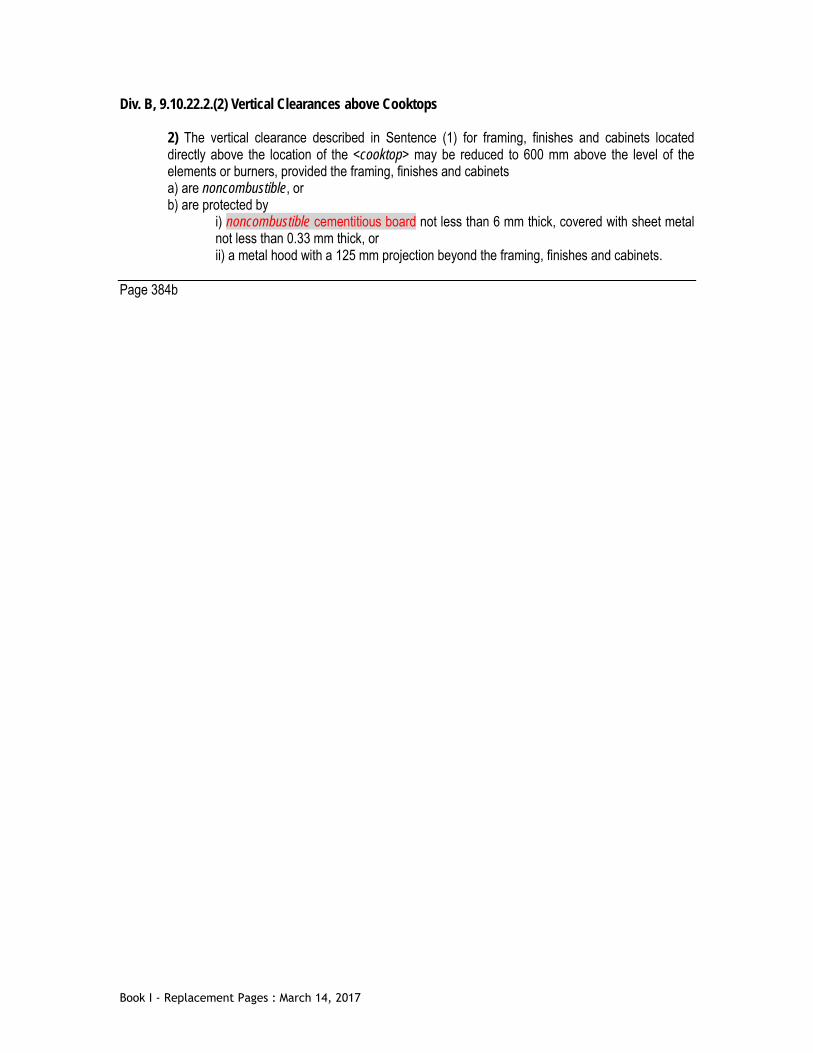
Div. B, 9.10.22.2.(2) Vertical Clearances above Cooktops
2) The vertical clearance described in Sentence (1) for framing, finishes and cabinets located directly above the location of the <cooktop> may be reduced to 600 mm above the level of the elements or burners, provided the framing, finishes and cabinets a) are noncombustible, or b) are protected by
i) noncombustible cementitious board not less than 6 mm thick, covered with sheet metal not less than 0.33 mm thick, or ii) a metal hood with a 125 mm projection beyond the framing, finishes and cabinets.
Page 384b
Book I - Replacement Pages : March 14, 2017

[This page intentionally left blank]
Book I - Replacement Pages : March 14, 2017
Div. B, 9.13.4. Soil Gas Control [Replace the header to Subsection 9.13.4. with the following] 9.13.4. Soil Gas Control (See Appendix A.) Page 388b
Book I - Replacement Pages : March 14, 2017

Div. B, 9.13.4. Soil Gas Control [Replace Articles 9.13.4.1. through 9.13.4.3. with the following] 9.13.4.1. Application and Scope
1) This Subsection applies to a) wall, roof and floor assemblies separating conditioned space from the ground, and b) the rough-in of a radon vent pipe to allow the future protection of conditioned space that is separated from the ground by a wall, roof or floor assembly. 2) This Subsection addresses the leakage of soil gas from the ground into the building.
9.13.4.2. Protection from Soil Gas Ingress
1) All wall, roof and floor assemblies separating conditioned space from the ground shall be protected by an air barrier system conforming to Subsection 9.25.3. 2) Except as permitted by Sentence (4), unless the space between the air barrier system and the ground is designed to be accessible for the future installation of a subfloor depressurization system, dwelling units and buildings containing residential occupancies shall be provided with the rough-in for a subfloor depressurization system conforming to Article 9.13.4.3. 3) Except as permitted by Sentence (4) or (5), where buildings are used for occupancies other than those described in Sentence (2), and are intended to be occupied on average for greater than 4 hours within a 24 hour period, protection from radon ingress and the means to address high radon concentrations in the future shall conform to a) Article 9.13.4.3., or b) Part 5 and 6 (see Article 5.4.1.1. and 6.2.1.1.). (See Appendix A.) 4) Buildings in locations classified as Radon Area 2 by Table C-3 in Appendix C need not conform to Sentences (2) and (3). 5) Buildings described in Clause 9.16.2.1.(2)(b) need not conform to Sentence (3).
9.13.4.3. Rough-in for a Subfloor Depressurization System (See Appendix A.)
1) Floors-on-ground shall be provided with a rough-in for subfloor depressurization consisting of a) a gas-permeable layer and a radon vent pipe, as described in Sentence (2), or b) a gas-permeable layer consisting of coarse clean granular material and a radon vent pipe, as described in Sentence (3).
[See page over]
Page 390a
Book I - Replacement Pages : March 14, 2017
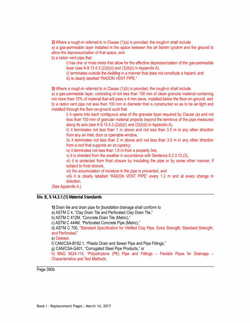
2) Where a rough-in referred to in Clause (1)(a) is provided, the rough-in shall include a) a gas-permeable layer installed in the space between the air barrier system and the ground to allow the depressurization of that space, and b) a radon vent pipe that
i) has one or more inlets that allow for the effective depressurization of the gas-permeable layer (see A-9.13.4.3.(2)(b)(i) and (3)(b)(i) in Appendix A), ii) terminates outside the building in a manner that does not constitute a hazard, and iii) is clearly labelled “RADON VENT PIPE.”
3) Where a rough-in referred to in Clause (1)(b) is provided, the rough-in shall include a) a gas-permeable layer, consisting of not less than 100 mm of clean granular material containing not more than 10% of material that will pass a 4 mm sieve, installed below the floor-on-ground, and b) a radon vent pipe not less than 100 mm in diameter that is constructed so as to be air-tight and installed through the floor-on-ground such that
i) it opens into each contiguous area of the granular layer required by Clause (a) and not less than 100 mm of granular material projects beyond the terminus of the pipe measured along its axis (see A-9.13.4.3.(2)(b)(i) and (3)(b)(i) in Appendix A), ii) it terminates not less than 1 m above and not less than 3.5 m in any other direction from any air inlet, door or openable window, iii) it terminates not less than 2 m above and not less than 3.5 m in any other direction from a roof that supports an occupancy, iv) it terminates not less than 1.8 m from a property line, v) it is shielded from the weather in accordance with Sentence 6.2.3.12.(3), vi) it is protected from frost closure by insulating the pipe or by some other manner, if subject to frost closure, vii) the accumulation of moisture in the pipe is prevented, and viii) it is clearly labelled “RADON VENT PIPE” every 1.2 m and at every change in direction.
(See Appendix A.) Div. B, 9.14.3.1.(1) Material Standards
1) Drain tile and drain pipe for foundation drainage shall conform to a) ASTM C 4, “Clay Drain Tile and Perforated Clay Drain Tile,” b) ASTM C 412M, “Concrete Drain Tile (Metric),” c) ASTM C 444M, “Perforated Concrete Pipe (Metric),” d) ASTM C 700, “Standard Specification for Vitrified Clay Pipe, Extra Strength, Standard Strength, and Perforated,” e) Deleted. f) CAN/CSA-B182.1, “Plastic Drain and Sewer Pipe and Pipe Fittings,” g) CAN/CSA-G401, “Corrugated Steel Pipe Products,” or h) BNQ 3624-115, “Polyethylene (PE) Pipe and Fittings – Flexible Pipes for Drainage – Characteristics and Test Methods.
Page 390b
Book I - Replacement Pages : March 14, 2017

[This page intentionally left blank]
Book I - Replacement Pages : March 14, 2017
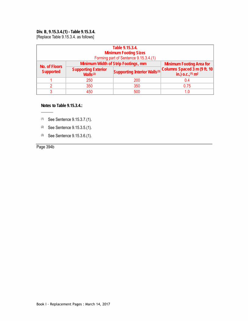
Div. B, 9.15.3.4.(1) - Table 9.15.3.4. [Replace Table 9.15.3.4. as follows]
Table 9.15.3.4. Minimum Footing Sizes
Forming part of Sentence 9.15.3.4.(1)
No. of Floors Supported
Minimum Width of Strip Footings, mm Minimum Footing Area for Columns Spaced 3 m (9 ft. 10
in.) o.c.,(1) m2 Supporting Exterior
Walls(2) Supporting Interior Walls(3)
1 250 200 0.4 2 350 350 0.75 3 450 500 1.0
Notes to Table 9.15.3.4.:
(1) See Sentence 9.15.3.7.(1). (2) See Sentence 9.15.3.5.(1). (3) See Sentence 9.15.3.6.(1).
Page 394b
Book I - Replacement Pages : March 14, 2017

[This page intentionally left blank]
Book I - Replacement Pages : March 14, 2017

Div. B, 9.16.2.1. Required Installation of Granular Material [Replace Article 9.16.2.1. as follows] 9.16.2.1. Required Installation of Material Beneath Floors-on-Ground
1) Except as provided in Sentence (2), a drainage layer shall be installed below floors-on-ground. (See Appendix A.) 2) The drainage layer required in Sentence (1) need not be installed below a) slabs in garages, carports or accessory buildings, or b) buildings of industrial occupancy where the nature of the process contained therein permits or requires the use of large openings in the building envelope even during the winter.
Div. B, 9.16.2.2.(4) Support of Floors
4) Fill beneath floors-on-ground need not be compacted where the material is coarse clean granular material containing not more than 10 {per cent} of material that will pass a 4 mm sieve.
Page 400b
Book I - Replacement Pages : March 14, 2017

Div. B, 9.23.16.5.(2) Lumber Roof Sheathing
2) Lumber roof sheathing shall be installed diagonally, where a) the seismic spectral response acceleration, Sa(0.2), is greater than 0.70 but not greater than 1.2, or b) the 1-in-50 hourly wind pressure is equal to or greater than 0.80 kPa but less than 1.20 kPa.
Div. B, 9.23.16.7.(3) Thickness or Rating
3) Asphalt-coated or asphalt-impregnated fibreboard not less than 11.1 mm thick conforming to CAN/ULC-S706, “Wood Fibre Insulating Boards for Buildings,” is permitted to be used as a roof sheathing over supports spaced not more than 400 mm o.c. provided the roofing consists of a) a continuous sheet of galvanized steel not less than 0.33 mm in thickness, or b) a continuous sheet of aluminum not less than 0.61 mm in thickness.
Page 446a
Book I - Replacement Pages : March 14, 2017

[This page intentionally left blank]
Book I - Replacement Pages : March 14, 2017

[This page intentionally left blank]
Book I - Replacement Pages : March 14, 2017

Div. B, 9.25.2.1.(1) Required Insulation
1) All walls, ceilings and floors separating heated space from unheated space, the exterior air or the exterior soil shall be provided with sufficient thermal insulation to prevent moisture condensation on their room side during the winter and to ensure comfortable conditions for the occupants. (See A-9.1.1.1.(1) in Appendix A and Part 10)
Div. B, 9.25.2.2.(1) Insulation Materials
1) Except as required in Sentence (2), thermal insulation shall conform to the requirements of a) CAN/CGSB-51.25-M, “Thermal Insulation, Phenolic, Faced,” b) CGSB 51-GP-27M, “Thermal Insulation, Polystyrene, Loose Fill,” c) CAN/ULC-S701, “Thermal Insulation, Polystyrene, Boards and Pipe Covering,” d) CAN/ULC-S702, “Mineral Fibre Thermal Insulation for Buildings,” e) CAN/ULC-S703, “Cellulose Fibre Insulation (CFI) for Buildings,” f) CAN/ULC-S704, “Thermal Insulation, Polyurethane and Polyisocyanurate, Boards, Faced,” g) CAN/ULC-S705.1, “Thermal Insulation – Spray Applied Rigid Polyurethane Foam, Medium Density – Material - Specification,” or h) CAN/ULC-S706, “Wood Fibre Insulating Boards for Buildings.”
Page 450b
Book I - Replacement Pages : March 14, 2017
Div. B, 9.25.2.3.(6) Installation of Thermal Insulation
6) Where insulation is exposed to the weather and subject to mechanical damage, it shall be protected with not less than a) Deleted. b) 6 mm preservative-treated plywood, or c) 12 mm cement parging on wire lath applied to the exposed face and edge.
Page 452a
Book I - Replacement Pages : March 14, 2017

[This page intentionally left blank]
Book I - Replacement Pages : March 14, 2017

Div. B, 9.26.2.1.(1) Material Standards
1) Roofing materials shall conform to a) CAN/CGSB-37.4-M, “Fibrated, Cutback Asphalt, Lap Cement for Asphalt Roofing,” b) CAN/CGSB-37.5-M, “Cutback Asphalt Plastic, Cement,” c) CAN/CGSB-37.8-M, “Asphalt, Cutback, Filled, for Roof Coating,” d) CGSB 37-GP-9Ma, “Primer, Asphalt, Unfilled, for Asphalt Roofing, Dampproofing and Waterproofing,” e) CGSB 37-GP-21M, “Tar, Cutback, Fibrated, for Roof Coating,” f) CAN/CGSB-37.50-M, “Hot-Applied, Rubberized Asphalt for Roofing and Waterproofing,” g) CGSB 37-GP-52M, “Roofing and Waterproofing Membrane, Sheet Applied, Elastomeric,” h) CAN/CGSB-37.54, “Polyvinyl Chloride Roofing and Waterproofing Membrane,” i) CGSB 37-GP-56M, “Membrane, Modified, Bituminous, Prefabricated, and Reinforced for Roofing,” j) CGSB 41-GP-6M, “Sheets, Thermosetting Polyester Plastics, Glass Fiber Reinforced,” k) CAN/CGSB-51.32-M, “Sheathing, Membrane, Breather Type,” l) CSA A123.1/A123.5, “Asphalt Shingles Made From Organic Felt and Surfaced with Mineral Granules/ Asphalt Shingles Made From Glass Felt and Surfaced with Mineral Granules,” m) CAN/CSA-A123.2, “Asphalt-Coated Roofing Sheets,” n) CSA A123.3, “Asphalt Saturated Organic Roofing Felt,” o) CAN/CSA-A123.4, “Asphalt for Constructing Built-Up Roof Coverings and Waterproofing Systems,” p) CSA A123.17, “Asphalt Glass Felt Used in Roofing and Waterproofing,” q) CAN/CSA-A220 Series, “Concrete Roof Tiles,” r) CSA O118.1, “Western Red Cedar Shakes and Shingles,” or s) CSA O118.2, “Eastern White Cedar Shingles.”
Page 456a
Book I - Replacement Pages : March 14, 2017

Div. B, 9.26.3.1.(1) Slope Replace Table 9.26.3.1. as follows
Table 9.26.3.1. Roofing Types and Slope Limits
Forming part of Sentence 9.26.3.1.(1) Type of Roofing Minimum Slope Maximum Slope Asbestos-Cement Corrugated Sheets 1 in 4 no limit Asphalt Shingles Low slope application 1 in 6 no limit Normal application 1 in 3 no limit Built-up Roofing Asphalt base (without gravel) 1 in 25 1 in 2 Asphalt base (gravelled) 1 in 50(1) 1 in 4 Coal-tar base (gravelled) 1 in 50(1) 1 in 25 Cold process 1 in 25 1 in 1.33 Cedar Shakes 1 in 3 no limit Clay Tile 1 in 2 no limit Glass Fibre Reinforced Polyester Roofing Panels 1 in 4 no limit Modified Bituminous Membranes 1 in 50 1 in 4 Profiled Metal Roofing 1 in 4(1) no limit Roll Roofing 480 mm wide selvage asphalt roofing 1 in 6 no limit Cold application felt 1 in 50 1 in 1.33 Smooth and mineral surfaced 1 in 4 no limit Sheet Metal Shingles 1 in 4(1) no limit Slate Shingles 1 in 2 no limit Wood Shingles 1 in 4 no limit Notes to Table 9.26.3.1.:
(1) See Sentence 9.26.3.1.(3). Page 456b
Book I - Replacement Pages : March 14, 2017
Div. B, 9.26.17.1.(1) Installation
1) Except as provided in Sentence 9.23.16.1.(1), concrete roof tiles shall be installed according to CAN/CSA-A220 Series, “Concrete Roof Tiles.” (See Appendix A.)
Page 464a
Book I - Replacement Pages : March 14, 2017

[This page intentionally left blank]
Book I - Replacement Pages : March 14, 2017

[This page intentionally left blank]
Book I - Replacement Pages : March 14, 2017

Div. B, 9.27.8.5.(1) Lapped Strip Siding 1) Plywood applied in horizontal lapped strips shall have not less than a 2 mm gap provided at the butted ends, which shall be caulked. Page 472b
Book I - Replacement Pages : March 14, 2017

Div. B, 9.29.8.1.(1) Material Standard
1) Insulating fibreboard shall conform to CAN/ULC-S706, “Wood Fibre Insulating Boards for Buildings.”
Page 480a
Book I - Replacement Pages : March 14, 2017

[This page intentionally left blank]
Book I - Replacement Pages : March 14, 2017

[This page intentionally left blank]
Book I - Replacement Pages : March 14, 2017

Div. B, 9.30.5.1.(1) Materials
1) Resilient flooring used on concrete slabs supported on ground shall consist of asphalt, rubber, vinyl-asbestos, unbacked vinyl or vinyl with an inorganic type backing.
Page 484b
Book I - Replacement Pages : March 14, 2017

[This page intentionally left blank]
Book I - Replacement Pages : March 14, 2017

Div. B, 9.32.3.7.(1) Kitchen and Bathroom Ventilation Exhaust Fan Capacity Ratings
1) Kitchen and bathroom ventilation exhaust fan capacity ratings shall be based on air flow performance at 50 pa external static pressure as determined in accordance with a) HVI 916, “Airflow Test Procedure,” or b) CAN/CSA-C260-M, “Rating the Performance of Residential Mechanical Ventilating Equipment.”
Page 488b
Book I - Replacement Pages : March 14, 2017
Div. B, 9.33.5.1.(1) Capacity of Heating Appliances
1) The required capacity of heating appliances located in a dwelling unit and serving only that dwelling unit, shall be determined in accordance with CSA F280, “Determining the Required Capacity of Residential Space Heating and Cooling Appliances,” except that the design temperatures shall conform to Subsection 9.33.3.
Page 494a
Book I - Replacement Pages : March 14, 2017

[This page intentionally left blank]
Book I - Replacement Pages : March 14, 2017

Div. B, 9.34.1.1.(2) Standard for Electrical Installations
2) In addition to the requirements of Sentence (1), electrical installations in a one-family dwelling required to conform to Article 9.37.3.1. shall also comply with the following: a) the electrical service size shall be based on the demand load calculated on the total area of the dwelling unit, provided that:
i) for each electrical range additional to the first range, 6kw demand shall be added for a rating of 12 kw or less, plus 40 per cent of the amount by which the rating of the range exceeds 12 kw, and ii) except for the first electrical range referred to in (a)(i), for each electrical appliance exceeding 1500 watts additional to those provided for one-family use, 100 per cent of the rating of such appliance shall be added,
b) general circuit branch wiring may be interconnected between outlets located in the principal dwelling and the secondary suite, and c) except as permitted by Sentence 11.4.3.1.(5), a single panel board may supply electrical loads of the principal dwelling and the secondary suite, provided that it is located within the building in a common area accessible to all occupants of the building.
Page 500a
Book I - Replacement Pages : March 14, 2017

[This page intentionally left blank]
Book I - Replacement Pages : March 14, 2017

Div. B, 9.37.3.1.(1) Specific Requirements
1) In addition to the requirements of this Part, a one-family dwelling with secondary suite or a lock-off unit shall be constructed in conformance with a) the fire compartmentation requirements in Sentence 9.10.9.14.(1), b) the installation of smoke alarms in Subsection 9.10.19., and c) the installation of electrical facilities in Subsection 9.34.1.
Div. B, 9.37.4.1.(3) Specific Requirements
3) Each dwelling unit and its secondary suite or lock-off unit shall be separated from each other by a) a fire separation complying with Sentence 9.10.9.14.(1), and b) tightly fitted building service penetrations.
Page 504a
Book I - Replacement Pages : March 14, 2017

[This page intentionally left blank]
Book I - Replacement Pages : March 14, 2017

[This page intentionally left blank]
Book I - Replacement Pages : March 14, 2017

Div. B, 10.2.1.1.(1) Design
1) Except as provided in Sentence (2) {and Subsection 10.2.2. , all buildings shall be designed and constructed to conform to a) {ANSI/ASHRAE/IESNA 90.1-2010, “Energy Standard for Buildings, except Low-Rise Residential Buildings”, excluding Section 8 Power, 8.4.2. Automatic Receptacle Control, and
i) designed with a climate zone of 5, ii) designed with ventilation in conformance with ASHRAE 62-2001 (except addendum n), iii) designed with vestibules located at all doors used to access a building with a gross floor area of more than 278.7 m2 (see Sentence (7)), and iv) if designed in accordance with ASHRAE 90.1-2010, Section 11, the 5 per cent in Table 11.3.1.5. Building Envelope, Exception a., shall be replaced by 2 per cent, v) need not comply with the Fenestration Orientation provisions of ASHRAE 90.1, Article 5.5.4.5., vi) need not be provided with Automatic Receptacle Control, per ASHRAE 90.1, Article 8.4.2., and vii) if designed in accordance with lighting control per ASHRAE 90.1 Article 9.4.1.3.(b), the maximum period of no activity is reduced to 20 min; or
b) the National Energy Code of Canada for Buildings 2011 (NECB), except that where NECB refers to the National Building Code of Canada (NBC) the provisions of this By-law shall apply, and designed
i) with a climate zone of 4, ii) with ventilation in conformance with ASHRAE 62-2001 (except addendum n) iii) with vestibules located at all doors used to access a building with a gross floor area of more than 278.7 m2 (see Sentence (7)), iv) with window-to-wall and skylight-to-roof area ratios of the reference building to a maximum of 40 per cent for windows and to a maximum of 5 per cent for skylights, identical to area ratios of the proposed building, v) with a vertical glazing Solar Heat Gain Coefficient which does not exceed an assembly maximum of 0.40, vi) with a Skylight Solar Heat Gain Coefficient without curb, or with curb and glass, which does not exceed an assembly maximum of 0.49, where the ratio of the aggregate skylight area to roof area is less than or equal to 2.0 per cent, vii) with a Skylight Solar Heat Gain Coefficient without curb, or with curb and glass, which does not exceed an assembly maximum of 0.39, where the ratio of the aggregate skylight area to roof area is greater than 2.0 per cent and less than or equal to 5.0 per cent, viii) with a Skylight Solar Heat Gain Coefficient with curb and plastic which does not exceed an assembly maximum of 0.77, where the ratio of the aggregate skylight area to roof area is less than or equal to 2.0 per cent, and ix) with a Skylight Solar Heat Gain Coefficient with curb and plastic which does not exceed an assembly maximum of 0.62, where the ratio of the aggregate skylight area to roof area is greater than 2.0 per cent and less than or equal to 5.0 per cent.
Page 538b
Book I - Replacement Pages : March 14, 2017
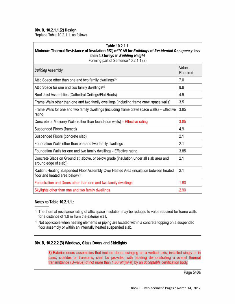
Div. B, 10.2.1.1.(2) Design Replace Table 10.2.1.1. as follows
Table 10.2.1.1. Minimum Thermal Resistance of Insulation RSI, m2°C/W for Buildings of Residential Occupancy less
than 4 Storeys in Building Height Forming part of Sentence 10.2.1.1.(2)
Building Assembly Value Required
Attic Space other than one and two family dwellings(1) 7.0 Attic Space for one and two family dwellings(1) 8.8 Roof Joist Assemblies (Cathedral Ceilings/Flat Roofs) 4.9 Frame Walls other than one and two family dwellings (including frame crawl space walls) 3.5 Frame Walls for one and two family dwellings (including frame crawl space walls) – Effective rating
3.85
Concrete or Masonry Walls (other than foundation walls) – Effective rating 3.85 Suspended Floors (framed) 4.9 Suspended Floors (concrete slab) 2.1 Foundation Walls other than one and two family dwellings 2.1 Foundation Walls for one and two family dwellings - Effective rating 3.85 Concrete Slabs on Ground at, above, or below grade (insulation under all slab area and around edge of slab))
2.1
Radiant Heating Suspended Floor Assembly Over Heated Area (insulation between heated floor and heated area below)(4)
2.1
Fenestration and Doors other than one and two family dwellings 1.80 Skylights other than one and two family dwellings 2.90 Notes to Table 10.2.1.1.:
(1) The thermal resistance rating of attic space insulation may be reduced to value required for frame walls for a distance of 1.0 m from the exterior wall.
(4) Not applicable when heating elements or piping are located within a concrete topping on a suspended floor assembly or within an internally heated suspended slab.
Div. B, 10.2.2.2.(3) Windows, Glass Doors and Sidelights
3) Exterior doors assemblies that include doors swinging on a vertical axis, installed singly or in pairs, sidelites or transoms, shall be provided with labeling demonstrating a overall thermal transmittance (U-value) of not more than 1.80 W/(m2∙K) by an acceptable certification body.
Page 540a
Book I - Replacement Pages : March 14, 2017

[This page intentionally left blank]
Book I - Replacement Pages : March 14, 2017

[This page intentionally left blank]
Book I - Replacement Pages : March 14, 2017

Div. B, 10.2.2.12.(2) EnerGuide Rating System Audit
2) A dwelling unit that is 112 square metres or smaller and has a Normalized Leakage Area (NLA) of 2.10 or lower, shall have a maximum of 3.5 air changes per hour or be sealed according to good engineering practice as described in Appendix A.
Div. B, 10.2.3.1. Electric Vehicle Charging for Buildings (See Appendix A)
1) The electrical installations, including the service capacity of the installation, the number and distribution of circuits and receptacles, shall meet the requirements of the “Electrical Safety Regulation.” 2) Except as provided by Sentence (3), each storage garage or carport in one-family dwellings, two-family dwellings, one-family dwellings or two family dwellings with secondary suites or lock-off units, or laneway houses shall be provided with an electrical outlet, a receptacle or electric vehicle supply equipment where applicable, supplied by a branch circuit rated not less than 40 A at the nominal voltage of 208 V or 240 V as applicable and labelled to identify its intended use with the electric vehicle supply equipment. 3) Where the requirements of Sentence (2) would cause the dwelling unit calculated load to exceed 200 A, the installation of a 40 A branch circuit may be omitted provided that a minimum nominal trade size of 21 raceway supplied with pull string leading from the dwelling unit panelboard to an electrical outlet box is installed in the storage garage or carport and is labelled to identify its intended use with the electric vehicle supply equipment. 4) One residential parking stall in each group of five residential parking stalls, and, one residential parking stall in any group of less than five residential parking stalls, in a multi-family building or in the multi-family component of a mixed use building that includes three or more dwelling units shall be provided with an electrical outlet, a receptacle or electric vehicle supply equipment where applicable, for the use of electric vehicle charging. 5) One commercial parking stall in each group of 10 commercial parking stalls, and one commercial parking stall in any group of less than 10 commercial parking stalls, in a commercial building, including the commercial component of a mixed use building shall be provided with an electrical outlet, a receptacle or electric vehicle supply equipment where applicable, for the use of electric vehicle charging. 6) The electrical outlet, receptacle or supply equipment described in Sentences (4) and (5) shall be supplied by a branch circuit rated not less than 40 A at the nominal voltage of 208 V or 240 V as applicable.
Div. B, 10.2.3.2.(1) Electrical Rooms
1) In a multi-family building or the multi-family component of a mixed use building, with three or more dwelling units, an electrical room shall be designed with sufficient space for the future installation of electrical equipment necessary to support electric vehicle charging in all residential parking stalls.
Page 542b
Book I - Replacement Pages : March 14, 2017

[This page intentionally left blank]
Book I - Replacement Pages : March 14, 2017
Div. B, 11.2.1.2.(2) & (3) General Requirements
2) Except as provided in Sentences (3) to (9) inclusive, and Articles 11.2.1.3. to 11.2.1.11. inclusive, where an alteration is made to an existing building, the alteration shall comply with this By-law and the existing building shall be a) upgraded to an acceptable level as defined in the existing building upgrade mechanism model in Division B Appendix A (See Appendix Note A-11.2.1.2.), except that existing lighting exceeding the Lighting Power Density of ASHRAE 90.1 -2007 shall be removed within existing spaces of a suite within the scope of a project, or b) upgraded to the satisfaction of the Chief Building Official where the owner demonstrates that the design levels, as defined by the upgrade mechanism model in Division B Appendix A, present a hardship for the owner. 3) Except as required by Sentence (9) and changes of major occupancy in a small suite, where an alteration does not involve an addition or a change in major occupancy, except for a change of major occupancy to a small suite, further upgrading to an existing building is not a requirement of this By-law provided a) construction or a full upgrade of the building occurred by means of a building permit issued on or after November 1, 1999, b) all unsafe conditions are corrected to the satisfaction of the Chief Building Official, and c) all new work is in compliance with this By-law.
Page 546b
Book I - Replacement Pages : March 14, 2017

Div. B, 11.2.1.2.(8) & (9) General Requirements
7) Where there is a temporary change of major occupancy to an assembly occupancy for an arts and culture indoor event in a building which is classified as Group D offices, Group E retail, Group F Division 2 production or rehearsal studio, wholesale, warehouse, or factory, or Group F Division 2 artist studio without living accommodations, the upgrade requirements shall be based solely on Section 11.6. 8) Where there is a change of major occupancy in a building, and the aggregate area of the change in major occupancy within any 5 year period is greater than 50 per cent of the building area in a one storey building or greater than 100 per cent of the building area in a building of more than one storey, the entire building shall be upgraded to design upgrade levels F4, S4, N4, A4 and E3 as detailed in the upgrade mechanism model in Division B Appendix A. 9) The upgrade requirements for energy efficiency to existing buildings shall conform to the upgrade mechanism model in Division B Appendix A for energy efficiency except for a) buildings designed and constructed in conformance with ASHRAE 90.1-2007 or as deemed acceptable to the Chief Building Official, b) buildings designed and constructed in conformance with Article 9.25.2.1. Division B of Building By-law No. 9419, and c) buildings where the alteration is limited to the upgrade of energy related specific equipment, as listed in Table 11.2.1.2., provided the replacement equipment complies with industry standards for "high efficiency".
Page 548a
Book I - Replacement Pages : March 14, 2017

[This page intentionally left blank]
Book I - Replacement Pages : March 14, 2017

[This page intentionally left blank]
Book I - Replacement Pages : March 14, 2017

Div. B, 11.2.1.11.(5) Specific Upgrade Requirements for Float Homes and Marinas 5) A marina shall have an occupancy classification as specified in Sentences 12.2.2.1.(4) and (5) of Group F Division 3. Page 550b
Book I - Replacement Pages : March 14, 2017

[This page intentionally left blank]
Book I - Replacement Pages : March 14, 2017

Div. B, 11.3.2.1.(1) Group A1 up to 600 Auditorium Occupants
1) A Group A, Division 1 occupancy having an occupant load of no more than 600 may be permitted within the first storey and second storey of a building provided the building conforms to Sentence (2).
Page 550b
Book I - Replacement Pages : March 14, 2017

Div. B, 11.3.2.2.(1) Group A1 up to 300 Auditorium Occupants
1) A Group A, Division 1 occupancy having an auditorium occupant load of no more than 300, may be permitted within the first storey and second storey of a building, provided the building conforms to Sentence (2).
Div. B, 11.3.2.3.(1) Group A2 in Building More Than 3 Storeys
1) A Group A, Division 2 occupancy may be permitted within the first 3 storeys of a building which is more than three storeys in building height, provided the building conforms to Sentence (2), and provided a) where the occupancy is located on the third storey or where the building area exceeds 400 m2, the entire building shall be sprinklered or b) where the occupancy is located on the first storey or second storey, the building shall be sprinklered up to and including the storey containing the Group A2 occupancy.
Page 552a
Book I - Replacement Pages : March 14, 2017

[This page intentionally left blank]
Book I - Replacement Pages : March 14, 2017

Div. B, 11.4.2.2.(9) Alternative Acceptable Solutions
9) Manual stations are not required if the fire alarm system and the sprinkler water flow alarm are designed in accordance with Article 3.2.4.8.
Div. B, 11.4.3.1.(5) Alternative Acceptable Solutions
5) Where a single existing panel board is located in a common area within the building accessible to all occupants of the building, the panel board may supply electrical loads for both the principal dwelling and the secondary suite or lock-off unit. 6) For the purposes of determining building height, a one family dwelling constructed pursuant to a building permit issued prior to July 01, 1994 which is four storeys or less in height may be considered as 3 storeys in building height.
Div. B, 11.4.3.1.(6) Group A2 in Building More Than 3 Storeys
6) For the purposes of determining building height, a one family dwelling constructed pursuant to a building permit issued prior to July 01, 1994 which is four storeys or less in height may be considered as 3 storeys in building height.
Page 560a
Book I - Replacement Pages : March 14, 2017
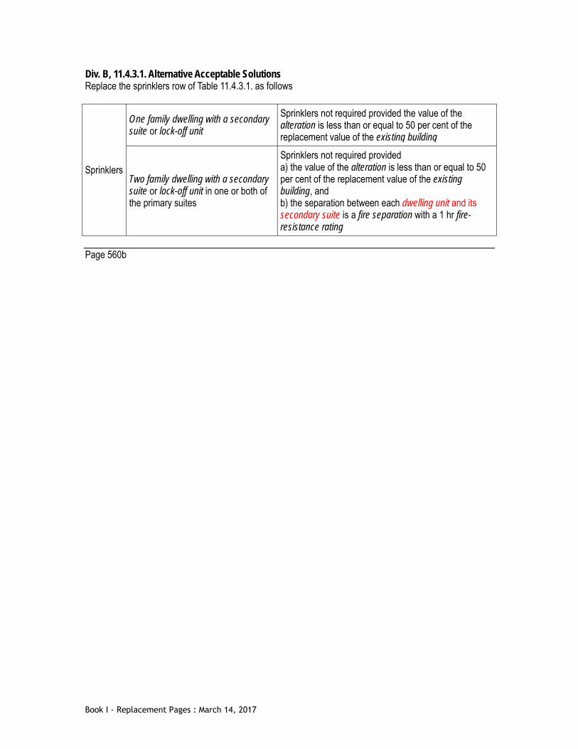
Div. B, 11.4.3.1. Alternative Acceptable Solutions Replace the sprinklers row of Table 11.4.3.1. as follows
Sprinklers
One family dwelling with a secondary suite or lock-off unit
Sprinklers not required provided the value of the alteration is less than or equal to 50 per cent of the replacement value of the existing building
Two family dwelling with a secondary suite or lock-off unit in one or both of the primary suites
Sprinklers not required provided a) the value of the alteration is less than or equal to 50 per cent of the replacement value of the existing building, and b) the separation between each dwelling unit and its secondary suite is a fire separation with a 1 hr fire-resistance rating
Page 560b
Book I - Replacement Pages : March 14, 2017

[This page intentionally left blank]
Book I - Replacement Pages : March 14, 2017

Div. B, 11.6.2.1.(1) Alternative Acceptable Solutions
1) Where the occupancy of an existing building or portion of an existing building is classified as Group D offices, Group E retail, Group F Division 2 production or rehearsal studio, wholesale, warehouse, or factory, or Group F Division 2 artist studio without living accommodations, the major occupancy may be changed to a temporary Group A Division 2 major occupancy for an arts and culture indoor event if a) the maximum occupant load is no more than 250 persons, or not more than 60 persons in an artist studio, b) the arts and culture indoor event is located in the first storey or the storey below the first storey and has at least one exit that conforms to Clauses 3.8.3.19.(1)(d) or (e), c) emergency lighting is provided in washrooms and in locations leading from the arts and culture indoor event to the street as described in Sentence 3.2.7.3.(1),
i) inside washrooms or, in the case of a single toilet room, immediately outside the entrance door and visible under the closed toilet room door, and ii) in locations leading from arts and culture indoor event to the street as described in Sentence 3.2.7.3.(1),
d) portable fire extinguishers are installed in accordance with the Fire By-law, with at least one extinguisher at the main entrance and at each egress door leading from the arts and culture indoor event floor area, e) an approved fire emergency procedures and security plan with approved maximum occupant load is posted beside each portable extinguisher at the main entrance and at each egress door leading from the arts and culture indoor event, f) the building is equipped with a fire alarm system, or supervisory staff are designated to monitor egress and exit doors and to carry out an emergency evacuation in accordance with approved fire emergency procedure, and g) the storey below the first storey used for an arts and culture indoor event is equipped with a sprinkler system, h) the arts and culture indoor event has at least one accessible entrance, and i) the arts and culture indoor event has a means of egress in accordance with Article 3.8.3.19.
Page 568b
Book I - Replacement Pages : March 14, 2017

Div. B, 11.4.2.2.(9) Alternative Acceptable Solutions
9) Manual stations are not required if the fire alarm system and the sprinkler water flow alarm are designed in accordance with Article 3.2.4.8.
Div. B, 11.4.3.1.(5) Alternative Acceptable Solutions
5) Where a single existing panel board is located in a common area within the building accessible to all occupants of the building, the panel board may supply electrical loads for both the principal dwelling and the secondary suite or lock-off unit. 6) For the purposes of determining building height, a one family dwelling constructed pursuant to a building permit issued prior to July 01, 1994 which is four storeys or less in height may be considered as 3 storeys in building height.
Div. B, 11.4.3.1.(6) Group A2 in Building More Than 3 Storeys
6) For the purposes of determining building height, a one family dwelling constructed pursuant to a building permit issued prior to July 01, 1994 which is four storeys or less in height may be considered as 3 storeys in building height.
Page 560a
Book I - Replacement Pages : March 14, 2017

Div. B, 11.4.3.1. Alternative Acceptable Solutions Replace the sprinklers row of Table 11.4.3.1. as follows
Sprinklers
One family dwelling with a secondary suite or lock-off unit
Sprinklers not required provided the value of the alteration is less than or equal to 50 per cent of the replacement value of the existing building
Two family dwelling with a secondary suite or lock-off unit in one or both of the primary suites
Sprinklers not required provided a) the value of the alteration is less than or equal to 50 per cent of the replacement value of the existing building, and b) the separation between each dwelling unit and its secondary suite is a fire separation with a 1 hr fire-resistance rating
Page 560b
Book I - Replacement Pages : March 14, 2017

[This page intentionally left blank]
Book I - Replacement Pages : March 14, 2017

Div. C, 1.4.1.5.(5) Alternative Acceptable Solutions
5) The owner shall ensure that all underground storage tanks on the subject property that are intended for the storage of heating oil but have not been used for over 2 years are removed and any associated contamination is remediated to the applicable standards as prescribed in the Contaminated Sites Regulation. All work must be completed in accordance with the requirements of the Vancouver Fire By-law.
Page 580b
Book I - Replacement Pages : March 14, 2017

[This page intentionally left blank]
Book I - Replacement Pages : March 14, 2017

Div. C, 1.5.4.2.(1) Delivery of Order
1) The Chief Building Official may order a) a person who contravenes any provision of this By-law, to comply with the provision within a specified time, b) a person to allow the Chief Building Official to enter any building or premises at any reasonable time for the purpose of administering and enforcing this By-law, c) work to stop on a building or any part thereof, if such work is proceeding in contravention of a provision of this By-law or another enactment, or if there is deemed to be an unsafe condition, d) the removal of an unauthorized encroachment on public property, e) the removal of any building or part thereof constructed in contravention of a provision of this By-law, f) the cessation of any occupancy in contravention of a provision of this By-law, g) the cessation of any occupancy if an unsafe condition exists, and h) the correction of an unsafe condition.
Page 586b
Book I - Replacement Pages : March 14, 2017
Div. C, 1.5.4.6.(1) Delivery of Order
1) The Chief Building Official may deliver an order a) by mailing the order by registered mail and by regular mail to the owner at the owner’s address as it appears on the records of the Assessment Authority of British Columbia, and posting the order on the premises which are the subject of the order, b) by sending the order by electronic mail to the electronic mail address of the owner or a representative of the owner, or c) by delivery of the order by hand to the owner or a representative of the owner.
Page 588a
Book I - Replacement Pages : March 14, 2017

[This page intentionally left blank]
Book I - Replacement Pages : March 14, 2017

[This page intentionally left blank]
Book I - Replacement Pages : March 14, 2017

Div. C, 2.2.9.1.(1) Exemptions from Flood Construction Level Requirements
1) Flood construction level requirements do not apply to: a) alteration of an existing building, not including reconstruction as defined in this By-law. (See Appendix A), b) alteration of an existing building to increase the building area by less than 25 per cent of the total building area existing as of July 29, 1999, if i) the number of dwelling units is not increased, ii) there is no further encroachment into setbacks required by this By-law, and iii) there is no further reduction in the flood construction level, c) enclosed parking areas, including bicycle and residential storage areas, in a multiple dwelling, if there is i) an unobstructed non-mechanized means of pedestrian ingress and egress to the areas, above the flood construction level, and ii) a sign posted at all entry points warning of the risk of flood damage, d) buildings and portions of buildings used as a carport or garage, e) non-residential accessory buildings, and f) loading facilities used for water oriented industry.
Page 620b
Book I - Replacement Pages : March 14, 2017
Appendix A of Div. B, Appendix Note A-1.2.1.2.(1) A-1.2.1.2.(1) Responsibility of Owner Sentence 1.1.1.1.(1) is not intended to imply that a person who becomes the owner of a building must bring the entire building into compliance with the Code. The Code applies only in the cases and to the extent specified by Article 1.1.1.1. and Part 11, and the owner of a building is therefore made responsible for ensuring the building complies with the Code by Sentence 1.2.1.2.(1) only in the cases and to the extent specified by Article 1.1.1.1. and Part 11. If none of the provisions in Sentence 1.1.1.1.(1) and Part 11 apply to the building, the owner is not required to make any changes to the building.
Page 638a
Book I - Replacement Pages : March 14, 2017

[This page intentionally left blank]
Book I - Replacement Pages : March 14, 2017

Appendix A of Div. B, Appendix Note A-1.3.1.2.(1) [Replace Table A-1.3.1.2.(1)]
Table A-1.3.1.2.(1) Documents Referenced in Appendices A, B and C of Book I (General) of the Building By-law
Forming part of Appendix Note A-1.3.1.2.(1) Issuing Agency Document Number(1) Title of Document(2) By-law Reference
AAMA 1304-02 Voluntary Specification for Forced Entry Resistance of Side-Hinged Door Systems
9.7.5.2.(2)
ASCE SEI/ASCE 8-02 Design of Cold-Formed Stainless Steel Structural Members
A-4.3.4.2.(1)
ANSI/ ASHRAE
62-2001 Ventilation for Acceptable Indoor Air Quality (except Addendum n)
A-9.25.5.2.
ANSI/UL 199 Standard for Safety of Automatic Sprinklers for Fire-Protection Service
A-3.2.5.12.(8)
ANSI/UL 1626 Standard for Safety of Residential Sprinklers for Fire-Protection Service
A-3.2.5.12.(8)
ASME B18.6.1-1981 Wood Screws (Inch Series) A-9.23.3.1.(3) ASME/CSA ASME A17.1-2010/CSA
B44-10 Safety Code for Elevators and Escalators A-3.5.2.1.(1)
ASTM A 390-06 Zinc-Coated (Galvanized) Steel Poultry Fence Fabric (Hexagonal and Straight Line)
Table A-9.10.3.1.B
ASTM C 516-08 Vermiculite Loose Fill Thermal Insulation A-9.25.2.4.(5) ASTM C 1193-11a Use of Joint Sealants A-Table 5.10.1.1.
A-9.27.4.2.(1) ASTM C 1299-03 Selection of Liquid-Applied Sealants A-Table 5.10.1.1.
A-9.27.4.2.(1) ASTM C 1472-10 Calculating Movement and Other Effects When
Establishing Sealant Joint Width A-Table 5.10.1.1. A-9.27.4.2.(1)
ASTM D 1037-06a Evaluating Properties of Wood-Base Fiber and Particle Panel Materials
A-9.23.15.2.(4)
ASTM D 1143/D 1143M-07e1 Deep Foundations Under Static Axial Compressive Load A-4.2.7.2.(2) ASTM E 336-05 Measurement of Airborne Sound Attenuation between
Rooms in Buildings A-9.11.1.1.(1)
ASTM E 492-09 Laboratory Measurement of Impact Sound Transmission Through Floor-Ceiling Assemblies Using The Tapping Machine
A-9.11.1.1.(1)
ASTM E 597-95 Determining a Single Number Rating of Airborne Sound Insulation for Use in Multi-Unit Building Specifications
A-9.11.1.1.(1)
ASTM E 736-00 Cohesion/Adhesion of Sprayed Fire-Resistive Materials Applied to Structural Members
Table A-9.10.3.1.B
ASTM E 1007-11e1 Field Measurement of Tapping Machine Impact Sound Transmission Through Floor-Ceiling Assemblies and Associated Support Structures
A-9.11.1.1.(1)
ASTM E 1300-04e1 Standard Practice for Determining Load Resistance of Glass in Buildings
4.3.6.1.(1) 9.6.1.3.(1)
ASTM F 842-04 Standard Test Methods for Measuring the Forced Entry Resistance of Sliding Door Assemblies, Excluding Glazing
9.7.5.1.(3)
Book I - Replacement Pages : March 14, 2017

Impact Vancouver Book II (Plumbing Systems) A-2.2.1.1.(1)(3)
A-3.2.1.1.(1)(3) A-4.1.6.4.(3) Appendix C
BC B.C. Reg. 100/2004 Electrical Safety Regulation A-3.2.4.21.(6)(a) A-9.34.2. A-9.35.2.2.(1)
BC B.C. Reg. 101/2004 Elevating Devices Safety Regulation A-3.5.2.1.(1) BC S.B.C. 1998, c. 43 Strata Property Act A-9.37.1.1. CCBFC NRCC 35951 Guidelines for Application of Part 3 of the National Building
Code of Canada to Existing Buildings A-1.1.1.2.(1)(3)
CCBFC NRCC 38732 National Farm Building Code of Canada 1995 A-1.4.1.2.(1)(3) A-Table 4.1.2.1. A-5.1.2.1.(1)
CCBFC NRCC 40383 User's Guide – NBC 1995, Fire Protection, Occupant Safety and Accessibility (Part 3)
A-1.1.1.2.(1)(3)
CCBFC NRCC 43963 User's Guide – NBC 1995, Application of Part 9 to Existing Buildings
A-1.1.1.2.(1)(3)
CCBFC NRCC 48192 User's Guide – NBC 2005, Structural Commentaries (Part 4 of Division B)
A-1.1.1.2.(1) A-4.1.1.3.(1) A-4.1.1.3.(2) A-3.2.5.12.(8) A-4.1.3.4.(1) A-4.1.3.5.(1) A-4.1.3.5.(3) A-Table 4.1.8.5. A-Table 4.1.8.6. A-5.1.4.2. Appendix C
CCBFC NRCC 53303 National Fire Code of Canada 2010 A-1.1.1.2.(1)(3) A-2.2.1.1.(1)(3) A-3.1.2.3.(1) A-3.2.1.1.(1)(3) A-3.2.4.7.(2) A-3.2.7.8.(3) A-3.3. A-3.3.1.2.(1) A-3.3.1.7.(1) A-3.3.3.1.(1) A-3.3.6.1.(1) B-3.2.6.
CCBFC NRCC 53543 User's Guide – NBC 2010, Structural Commentaries (Part 4 of Division B)
A-1.1.1.2.(1)(3) A-4.1.1.3.(1) A-4.1.1.3.(2) A-4.1.2.1. A-4.1.2.1.(1) A-4.1.3. A-4.1.3.2.(2) A-4.1.3.2.(4)
Book I - Replacement Pages : March 14, 2017

A-4.1.3.2.(5) A-4.1.3.3.(2) A-4.1.3.4.(1) A-4.1.3.5.(1) A-4.1.3.5.(3) A-4.1.3.6.(1) A-4.1.3.6.(2) A-4.1.3.6.(3) A-4.1.5.8. A-4.1.5.17. A-4.1.6.2. A-4.1.6.2.(4)(b) A-4.1.6.3.(2) A-4.1.6.4.(1) A-4.1.7.1.(1) to (3) A-4.1.7.1.(5)(a) to (c) A-4.1.7.1.(5)(d) A-4.1.7.1.(6)(a) A-4.1.7.1.(6)(c) A-4.1.7.1.(6)(d) and 4.1.7.2.(1)(b) A-4.1.7.2.(1) and (2) A-4.1.7.3.(1) A-4.1.8.2.(1) A-4.1.8.3.(4) A-4.1.8.3.(6) A-4.1.8.3.(7)(b) and (c) A-4.1.8.3.(8) A-4.1.8.4.(3) and Table 4.1.8.4.A. A-Table 4.1.8.5. A-Table 4.1.8.6. A-4.1.8.7.(1) A-4.1.8.9.(4) A-4.1.8.9.(5) A-4.1.8.11.(3) A-4.1.8.12.(1)(a) A-4.1.8.12.(1)(b) A-4.1.8.12.(3) A-4.1.8.12.(4)(a) A-4.1.8.13.(4) A-4.1.8.15.(1) A-4.1.8.15.(3) A-4.1.8.15.(4) A-4.1.8.15.(5) A-4.1.8.15.(6) A-4.1.8.15.(7) A-4.1.8.16.(1) A-4.1.8.16.(3)(a) A-4.1.8.16.(4) A-4.1.8.16.(5)(a)
Book I - Replacement Pages : March 14, 2017
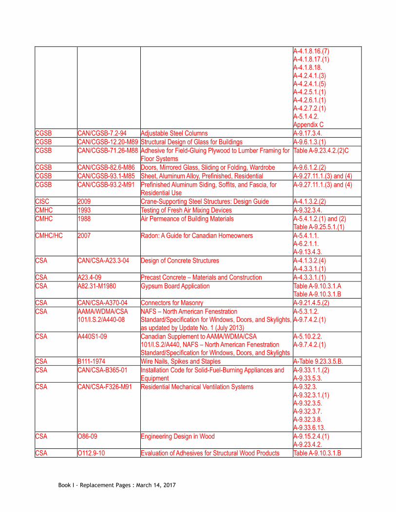
A-4.1.8.16.(7) A-4.1.8.17.(1) A-4.1.8.18. A-4.2.4.1.(3) A-4.2.4.1.(5) A-4.2.5.1.(1) A-4.2.6.1.(1) A-4.2.7.2.(1) A-5.1.4.2. Appendix C
CGSB CAN/CGSB-7.2-94 Adjustable Steel Columns A-9.17.3.4. CGSB CAN/CGSB-12.20-M89 Structural Design of Glass for Buildings A-9.6.1.3.(1) CGSB CAN/CGSB-71.26-M88 Adhesive for Field-Gluing Plywood to Lumber Framing for
Floor Systems Table A-9.23.4.2.(2)C
CGSB CAN/CGSB-82.6-M86 Doors, Mirrored Glass, Sliding or Folding, Wardrobe A-9.6.1.2.(2) CGSB CAN/CGSB-93.1-M85 Sheet, Aluminum Alloy, Prefinished, Residential A-9.27.11.1.(3) and (4) CGSB CAN/CGSB-93.2-M91 Prefinished Aluminum Siding, Soffits, and Fascia, for
Residential Use A-9.27.11.1.(3) and (4)
CISC 2009 Crane-Supporting Steel Structures: Design Guide A-4.1.3.2.(2) CMHC 1993 Testing of Fresh Air Mixing Devices A-9.32.3.4. CMHC 1988 Air Permeance of Building Materials A-5.4.1.2.(1) and (2)
Table A-9.25.5.1.(1) CMHC/HC 2007 Radon: A Guide for Canadian Homeowners A-5.4.1.1.
A-6.2.1.1. A-9.13.4.3.
CSA CAN/CSA-A23.3-04 Design of Concrete Structures A-4.1.3.2.(4) A-4.3.3.1.(1)
CSA A23.4-09 Precast Concrete – Materials and Construction A-4.3.3.1.(1) CSA A82.31-M1980 Gypsum Board Application Table A-9.10.3.1.A
Table A-9.10.3.1.B CSA CAN/CSA-A370-04 Connectors for Masonry A-9.21.4.5.(2) CSA AAMA/WDMA/CSA
101/I.S.2/A440-08 NAFS – North American Fenestration Standard/Specification for Windows, Doors, and Skylights, as updated by Update No. 1 (July 2013)
A-5.3.1.2. A-9.7.4.2.(1)
CSA A440S1-09 Canadian Supplement to AAMA/WDMA/CSA 101/I.S.2/A440, NAFS – North American Fenestration Standard/Specification for Windows, Doors, and Skylights
A-5.10.2.2. A-9.7.4.2.(1)
CSA B111-1974 Wire Nails, Spikes and Staples A-Table 9.23.3.5.B. CSA CAN/CSA-B365-01 Installation Code for Solid-Fuel-Burning Appliances and
Equipment A-9.33.1.1.(2) A-9.33.5.3.
CSA CAN/CSA-F326-M91 Residential Mechanical Ventilation Systems A-9.32.3. A-9.32.3.1.(1) A-9.32.3.5. A-9.32.3.7. A-9.32.3.8. A-9.33.6.13.
CSA O86-09 Engineering Design in Wood A-9.15.2.4.(1) A-9.23.4.2.
CSA O112.9-10 Evaluation of Adhesives for Structural Wood Products Table A-9.10.3.1.B
Book I - Replacement Pages : March 14, 2017
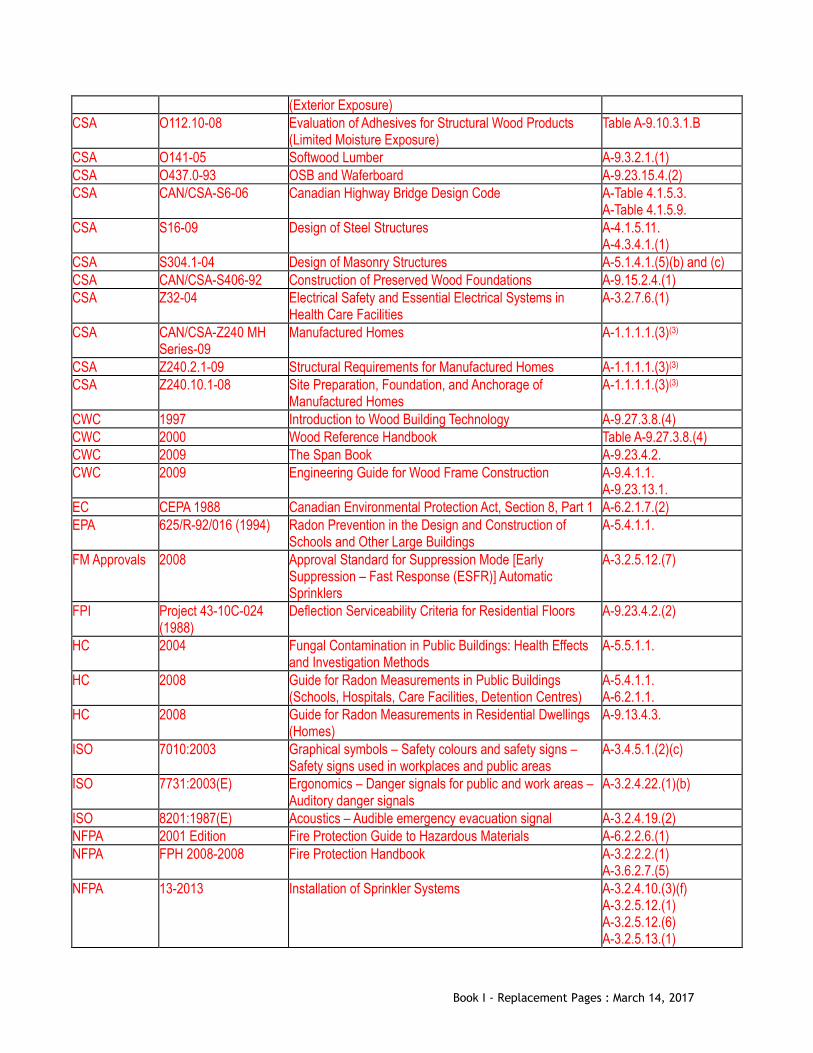
(Exterior Exposure) CSA O112.10-08 Evaluation of Adhesives for Structural Wood Products
(Limited Moisture Exposure) Table A-9.10.3.1.B
CSA O141-05 Softwood Lumber A-9.3.2.1.(1) CSA O437.0-93 OSB and Waferboard A-9.23.15.4.(2) CSA CAN/CSA-S6-06 Canadian Highway Bridge Design Code A-Table 4.1.5.3.
A-Table 4.1.5.9. CSA S16-09 Design of Steel Structures A-4.1.5.11.
A-4.3.4.1.(1) CSA S304.1-04 Design of Masonry Structures A-5.1.4.1.(5)(b) and (c) CSA CAN/CSA-S406-92 Construction of Preserved Wood Foundations A-9.15.2.4.(1) CSA Z32-04 Electrical Safety and Essential Electrical Systems in
Health Care Facilities A-3.2.7.6.(1)
CSA CAN/CSA-Z240 MH Series-09
Manufactured Homes A-1.1.1.1.(3)(3)
CSA Z240.2.1-09 Structural Requirements for Manufactured Homes A-1.1.1.1.(3)(3) CSA Z240.10.1-08 Site Preparation, Foundation, and Anchorage of
Manufactured Homes A-1.1.1.1.(3)(3)
CWC 1997 Introduction to Wood Building Technology A-9.27.3.8.(4) CWC 2000 Wood Reference Handbook Table A-9.27.3.8.(4) CWC 2009 The Span Book A-9.23.4.2. CWC 2009 Engineering Guide for Wood Frame Construction A-9.4.1.1.
A-9.23.13.1. EC CEPA 1988 Canadian Environmental Protection Act, Section 8, Part 1 A-6.2.1.7.(2) EPA 625/R-92/016 (1994) Radon Prevention in the Design and Construction of
Schools and Other Large Buildings A-5.4.1.1.
FM Approvals 2008 Approval Standard for Suppression Mode [Early Suppression – Fast Response (ESFR)] Automatic Sprinklers
A-3.2.5.12.(7)
FPI Project 43-10C-024 (1988)
Deflection Serviceability Criteria for Residential Floors A-9.23.4.2.(2)
HC 2004 Fungal Contamination in Public Buildings: Health Effects and Investigation Methods
A-5.5.1.1.
HC 2008 Guide for Radon Measurements in Public Buildings (Schools, Hospitals, Care Facilities, Detention Centres)
A-5.4.1.1. A-6.2.1.1.
HC 2008 Guide for Radon Measurements in Residential Dwellings (Homes)
A-9.13.4.3.
ISO 7010:2003 Graphical symbols – Safety colours and safety signs – Safety signs used in workplaces and public areas
A-3.4.5.1.(2)(c)
ISO 7731:2003(E) Ergonomics – Danger signals for public and work areas – Auditory danger signals
A-3.2.4.22.(1)(b)
ISO 8201:1987(E) Acoustics – Audible emergency evacuation signal A-3.2.4.19.(2) NFPA 2001 Edition Fire Protection Guide to Hazardous Materials A-6.2.2.6.(1) NFPA FPH 2008-2008 Fire Protection Handbook A-3.2.2.2.(1)
A-3.6.2.7.(5) NFPA 13-2013 Installation of Sprinkler Systems A-3.2.4.10.(3)(f)
A-3.2.5.12.(1) A-3.2.5.12.(6) A-3.2.5.13.(1)
Book I - Replacement Pages : March 14, 2017

A-3.2.8.2.(3) NFPA 13D-2010 Installation of Sprinkler Systems in One- and Two-Family
Dwellings and Manufactured Homes A-3.2.5.12.(6) A-3.2.5.12.(7) A-3.2.5.13.(1)
NFPA 13R-2010 Installation of Sprinkler Systems in Residential Occupancies up to and Including Four Stories in Height
A-3.2.5.12.(6) A-3.2.5.12.(7) A-3.2.5.13.(1)
NFPA 20-2010 Installation of Stationary Pumps for Fire Protection A-3.2.4.10.(3)(f) NFPA 30-2008 Flammable and Combustible Liquids Code A-6.2.2.6.(1) NFPA 30A-2008 Motor Fuel Dispensing Facilities and Repair Garages A-6.2.2.6.(1) NFPA 32-2007 Drycleaning Plants A-6.2.2.6.(1) NFPA 33-2007 Spray Application Using Flammable or Combustible
Materials A-6.2.2.6.(1)
NFPA 34-2007 Dipping and Coating Processes Using Flammable or Combustible Liquids
A-6.2.2.6.(1)
NFPA 35-2005 Manufacture of Organic Coatings A-6.2.2.6.(1) NFPA 36-2009 Solvent Extraction Plants A-6.2.2.6.(1) NFPA 40-2007 Storage and Handling of Cellulose Nitrate Film A-6.2.2.6.(1) NFPA 51-2007 Design and Installation of Oxygen-Fuel Gas Systems for
Welding, Cutting, and Allied Processes A-6.2.2.6.(1)
NFPA 51A-2006 Acetylene Cylinder Charging Plants A-6.2.2.6.(1) NFPA 55-2005 Storage, Use, and Handling of Compressed Gases and
Cryogenic Fluids in Portable and Stationary Containers, Cylinders, and Tanks
A-6.2.2.6.(1)
NFPA 61-2008 Prevention of Fires and Dust Explosions in Agricultural and Food Processing Facilities
A-6.2.2.6.(1)
NFPA 68-2007 Explosion Protection by Deflagration Venting A-3.6.2.7.(5) A-6.2.2.6.(1)
NFPA 69-2008 Explosion Prevention Systems A-3.6.2.7.(5) A-6.2.2.6.(1)
NFPA 72-2007 National Fire Alarm and Signaling Code A-3.2.4.22.(2) NFPA 80-2007 Fire Doors and Other Opening Protectives A-3.1.8.1.(2)
A-3.2.8.2.(3) NFPA 80A-2007 Protection of Buildings from Exterior Fire Exposures A-3 NFPA 85-2007 Boiler and Combustion Systems Hazards Code A-6.2.2.6.(1) NFPA 86-2007 Ovens and Furnaces A-6.2.2.6.(1) NFPA 88A-2007 Parking Structures A-6.2.2.6.(1) NFPA 91-2004 Exhaust Systems for Air Conveying of Vapors, Gases,
Mists, and Noncombustible Particulate Solids A-6.2.2.6.(1)
NFPA 96-2008 Ventilation Control and Fire Protection of Commercial Cooking Operations
A-3.3.1.2.(2) A-6.2.2.6.(1) A-9.10.1.4.(1)
NFPA 101-2009 Life Safety Code A-3.3.2.1.(2) NFPA 204-2007 Smoke and Heat Venting A-6.2.2.6.(1) NFPA 303-2006 Marinas and Boatyards A-6.2.2.6.(1) NFPA 307-2006 Construction and Fire Protection of Marine Terminals,
Piers, and Wharves A-6.2.2.6.(1)
NFPA 409-2004 Aircraft Hangars A-6.2.2.6.(1) NFPA 415-2008 Airport Terminal Buildings, Fueling, Ramp Drainage, A-6.2.2.6.(1)
Book I - Replacement Pages : March 14, 2017
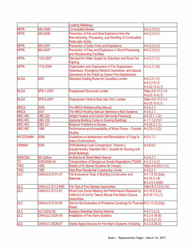
Loading Walkways NFPA 484-2009 Combustible Metals A-6.2.2.6.(1) NFPA 654-2006 Prevention of Fire and Dust Explosions from the
Manufacturing, Processing, and Handling of Combustible Particulate Solids
A-6.2.2.6.(1)
NFPA 655-2007 Prevention of Sulfur Fires and Explosions A-6.2.2.6.(1) NFPA 664-2007 Prevention of Fires and Explosions in Wood Processing
and Woodworking Facilities A-6.2.2.6.(1)
NFPA 1142-2007 Standard for Water Supply for Suburban and Rural Fire Fighting
A-3.2.5.7.(1)
NFPA 1710-2004 Organization and Deployment of Fire Suppression Operations, Emergency Medical Operations, and Special Operations to the Public by Career Fire Departments
A-3.2.3.1.(8)
NLGA 2007 Standard Grading Rules for Canadian Lumber A-9.3.2.1.(1) A-9.3.2.8.(1) A-9.23.10.4.(1)
NLGA SPS-1-2007 Fingerjoined Structural Lumber Table A-9.10.3.1.A A-9.23.10.4.(1)
NLGA SPS-3-2007 Fingerjoined 'Vertical Stud Use Only' Lumber Table A-9.10.3.1.A A-9.23.10.4.(1)
NRCA 2005 The NRCA Waterproofing Manual A-5.6.2.1. NRCA 2007 The NRCA Roofing Manual: Membrane Roof Systems A-5.6.2.1. NRC-IRC CBD 222 Airtight Houses and Carbon Monoxide Poisoning A-9.33.1.1.(2) NRC-IRC CBD 230 Applying Building Codes to Existing Buildings A-1.1.1.2.(1)(3) NRC-IRC CBD 231 Moisture Problems in Houses A-9.25.3.1.(1) NRC-IRC 1988 Performance and Acceptability of Wood Floors – Forintek
Studies A-9.23.4.2.(2)
NYCDOHMH 2008 Guidelines on Assessment and Remediation of Fungi in Indoor Environments
A-5.5.1.1.
OMMAH 2006 2006 Building Code Compendium, Volume 2, Supplementary Standard SB-7, Guards for Housing and Small Buildings
A-9.8.8.2.
SMACNA 6th Edition Architectural Sheet Metal Manual A-5.6.2.1. TC SOR/2008-34 Transportation of Dangerous Goods Regulations (TDGR) A-3.3.1.2.(1) TWC 1993 Details of Air Barrier Systems for Houses Table A-9.25.5.1.(1) TWC 1995 High-Rise Residential Construction Guide A-5.6.2.1. ULC CAN/ULC-S101-07 Fire Endurance Tests of Building Construction and
Materials A-3.1.5.12.(2)(e) A-9.10.3.1.B B-3.2.6.5.(6)(b)
ULC CAN/ULC-S112-M90 Fire Test of Fire-Damper Assemblies Table B-3.2.6.6.(1)C ULC CAN/ULC-S113-07 Wood Core Doors Meeting the Performance Required by
CAN/ULC-S104 for Twenty Minute Fire Rated Closure Assemblies
A-9.10.9.3.(2) A-9.10.13.2.(1)
ULC CAN/ULC-S124-06 Test for the Evaluation of Protective Coverings for Foamed Plastic
A-3.1.5.12.(2)(e)
ULC ULC-S332-93 Burglary Resisting Glazing Material A-9.7.5.2.(1) ULC CAN/ULC-S524-06 Installation of Fire Alarm Systems A-3.2.4.19.(8)
A-3.2.4.21.(7) ULC CAN/ULC-S526-07 Visible Signal Devices for Fire Alarm Systems, Including A-3.2.4.20.(2)
Book I - Replacement Pages : March 14, 2017
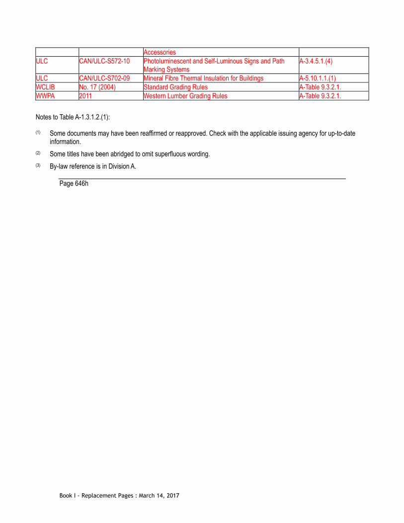
Accessories ULC CAN/ULC-S572-10 Photoluminescent and Self-Luminous Signs and Path
Marking Systems A-3.4.5.1.(4)
ULC CAN/ULC-S702-09 Mineral Fibre Thermal Insulation for Buildings A-5.10.1.1.(1) WCLIB No. 17 (2004) Standard Grading Rules A-Table 9.3.2.1. WWPA 2011 Western Lumber Grading Rules A-Table 9.3.2.1.
Notes to Table A-1.3.1.2.(1): (1) Some documents may have been reaffirmed or reapproved. Check with the applicable issuing agency for up-to-date
information. (2) Some titles have been abridged to omit superfluous wording. (3) By-law reference is in Division A.
Page 646h
Book I - Replacement Pages : March 14, 2017

Appendix A of Div. B, 3.1.2.1.(2) Major Occupancy Classification [Replace Group A, Division 2 as follows] Group A, Division 2
Art galleries Auditoria Bowling alleys Child Care Facilities Churches and similar places of worship Clubs, nonresidential Community halls Courtrooms Dance halls Exhibition halls (other than classified in Group E) Gymnasia Lecture halls Libraries Licensed beverage establishments Museums Passenger stations and depots Recreational piers Restaurants Schools and colleges, nonresidential Undertaking premises
Page 656a
Book I - Replacement Pages : March 14, 2017

[This page intentionally left blank]
Book I - Replacement Pages : March 14, 2017

[This page intentionally left blank]
Book I - Replacement Pages : March 14, 2017
Appendix A of Div. B, Appendix Note A-3.1.2.5.(3) A-3.1.2.5.(3) Daycare Facilities for Children A daycare facility for children is typically occupied for a period of less than 24 hours each day (i.e., is not a residential facility). The term “daycare” is not meant to exclude facilities that provide short term care during the night for a period of less than 24 hours each day. (See also A-3.3.2.16.) Page 658b
Book I - Replacement Pages : March 14, 2017

[This page intentionally left blank]
Book I - Replacement Pages : March 14, 2017

Appendix A of Div. B, Appendix Note A-3.3.2.16. A-3.3.2.16. Daycare Facilities with Children under 30 Months These daycare facilities are subject to additional requirements to address the unique profile of the occupants. (See also A-3.1.2.5.(3) ) Page 682b
Book I - Replacement Pages : March 14, 2017

Appendix A of Div. B, Appendix Note A-3.3.7.7.(2) A-3.3.7.7.(2) Security for Storage Garage The requirements of Sentence 3.3.7.7.(2) are intended to provide improved visibility into or out of a stair tower or vestibule which might otherwise occlude the line of sight of building occupants as a result of intervening construction. Glazing must provide the maximum practical improvement to visibility to improve occupant safety. The term ‘stair tower’ used in this Sentence is intended to apply to vertical stair enclosures connecting more than one floor or containing superimposed flights of stairs.
Page 684a
Book I - Replacement Pages : March 14, 2017

[This page intentionally left blank]
Book I - Replacement Pages : March 14, 2017

[This page intentionally left blank]
Book I - Replacement Pages : March 14, 2017
Appendix A of Div. B, Appendix Note A-4.1.5.8. A-4.1.5.8. Tributary Area Information on tributary area can be found in the Commentary entitled Live Loads in the User’s Guide – NBC 2010, Structural Commentaries (Part 4 of Division B). Page 694b
Book I - Replacement Pages : March 14, 2017

Appendix A of Div. B, Appendix Note A-5.10.2.2. A-5.10.2.2. Windows, Doors, Skylights and Other Glazed Products Design Values CSA A440S1 requires that the individual performance levels achieved by the product for structural resistance, water penetration resistance and air leakage resistance be reported on the product’s performance label. Storm Doors and Windows Where storm doors and storm windows are not incorporated in a rated window or door assembly, they should be designed and constructed to comply with the applicable requirements of Part 5 regarding such properties as appropriate air leakage and structural loads. Forced Entry Test Even though the performance label on rated windows, doors and skylights does not explicitly indicate that the product has passed the forced entry resistance test, products are required to pass this test in order to be rated. Installation and Field Testing of Windows, Doors, Skylights and Other Glazed Products Windows, doors, skylights, other glazed products and their components require installation details that are appropriately designed and constructed to provide acceptable overall performance of a building envelope assembly. Proper design of installation details provides the information necessary to integrate the window, door or skylight’s structure, air barrier, vapour barrier and water barrier functions into the overall design of the building envelope assembly for these functions. Proper construction of these details is necessary to achieve an appropriate level of long term performance. Further guidance on installation detailing for windows, doors, skylights and other glazed products and their components can be found in CSA A440.4, “Window, Door and Skylight Installation.” Field testing of installed windows, doors and skylights during construction can be an invaluable tool for verifying acceptable levels of performance for the installed system. Although not required by this Code, field testing early in the envelope construction phase is considered favourable such that discontinuities in the system can be readily identified and corrections made before construction of the entire assembly is completed. Additional field testing during the construction phases can also be used to monitor installation consistency. Further guidance on methods and guidelines for the field testing of windows, doors and skylights can be found in CSA A440.4, “Window, Door and Skylight Installation, Annex D – Field Testing of Window and Door Installations.” While this document does list previously identified industry performance data values, it is important to note that the user should utilize current specific performance requirements for a project as governed by the values developed in the referenced standard AAMA/WDMA/CSA101/I.S.2/A440, “NAFS – North American Fenestration Standard/Specification for Windows, Doors, and Skylights.” Field test procedures should be in accordance with referenced test standards, such as ASTM E783, “Standard Test Method for Field Measurement of Air Leakage Through Installed Exterior Windows and Doors” and ASTM E1105, “Standard Test Method for Field Determination of Water Penetration of Installed Exterior Windows, Skylights, Doors, and Curtain Walls, by Uniform or Cyclic Static Air Pressure Difference.”
Page 708a
Book I - Replacement Pages : March 14, 2017

Appendix A of Div. B, Appendix Note A-5.10.2.2. [see over] A-5.10.2.2. Windows, Doors, Skylights and Other Glazed Products A-5.10.2.2.(1) Two Compliance Paths It is intended that any fenestration product that conforms to this Part may choose to comply with either Clause (a) or Clause (b) of Sentence 5.10.2.2.(1). Even if a product is in scope of the standards referenced via Clause (b) (NAFS and the Canadian Supplement to NAFS), the compliance path in Clause (a) may be used. However, it is not intended that the compliance path in Clause (b) be used where fenestration products are not within the scope of the referenced standards. A-5.10.2.2.(2) Other Glazed Products Glazed products such as curtain walls or sloped glazing that are not typically considered windows but are installed as part of a separation described in Sentence 5.10.2.1.(1) are not within the scope of the referenced standards and therefore must conform to Subsection 5.1.4. and Sections 5.3., 5.4. and 5.6. A-5.10.2.2.(4) Loads and Procedures For windows within the scope of the “Canadian Supplement” referred to in Sentence 5.10.2.2.(1), structural and wind loads are included and may be calculated in accordance with that standard. As an alternative, structural and wind loads from Section 5.2. may be used to select fenestration products that are appropriate for the point of installation. Values derived from the referenced standard, which uses a simplified calculation method, are typically higher than those derived from calculations done in conformance with Section 5.2. Page 708b
Book I - Replacement Pages : March 14, 2017

Appendix A of Div. B, Appendix Note A-6.2.2.6.(1) A-6.2.2.6.(1) NFPA Publications Pertaining to the Heating, Ventilating and Air-Conditioning of Spaces Containing Hazardous Gases, Dusts or Liquids NFPA 30, “Flammable and Combustible Liquids Code” NFPA 30A, “Motor Fuel Dispensing Facilities and Repair Garages” NFPA 32, “Drycleaning Plants” NFPA 33, “Spray Application Using Flammable or Combustible Materials” NFPA 34, “Dipping and Coating Processes Using Flammable or Combustible Liquids” NFPA 35, “Manufacture of Organic Coatings” NFPA 36, “Solvent Extraction Plants” NFPA 40, “Storage and Handling of Cellulose Nitrate Film” NFPA 51, “Design and Installation of Oxygen-Fuel Gas Systems for Welding, Cutting, and Allied Processes” NFPA 51A, “Acetylene Cylinder Charging Plants” NFPA 55, “Compressed Gases and Cryogenic Fluids Code” NFPA 61, “Prevention of Fires and Dust Explosions in Agricultural and Food Processing Facilities” NFPA 68, “Explosion Protection by Deflagration Venting” NFPA 69, “Explosion Prevention Systems” NFPA 85, “Boiler and Combustion Systems Hazards Code” NFPA 86, “Ovens and Furnaces” NFPA 88A, “Parking Structures” NFPA 91, “Exhaust Systems for Air Conveying of Vapors, Gases, Mists, and Noncombustible Particulate Solids” NFPA 96, “Ventilation Control and Fire Protection of Commercial Cooking Operations” NFPA 204, “Smoke and Heat Venting” NFPA 303, “Marinas and Boatyards” NFPA 307, “Construction and Fire Protection of Marine Terminals, Piers, and Wharves” NFPA 409, “Aircraft Hangars” NFPA 415, “Airport Terminal Buildings, Fueling, Ramp Drainage, Loading Walkways” NFPA 484, “Combustible Metals” NFPA 654, “Prevention of Fire and Dust Explosions from the Manufacturing, Processing, and Handling of Combustible Particulate Solids” NFPA 655, “Prevention of Sulfur Fires and Explosions” NFPA 664, “Prevention of Fires and Explosions in Wood Processing and Woodworking Facilities” NFPA “Fire Protection Guide to Hazardous Materials”
Page 710a
Book I - Replacement Pages : March 14, 2017

[This page intentionally left blank]
Book I - Replacement Pages : March 14, 2017
Appendix A of Div. B, Appendix Note A-9.3.2.1.(1) [Replace the 1st paragraph following Table A-9.3.2.1.(1)A as follows] Canadian lumber is graded to the NLGA 2010, “Standard Grading Rules for Canadian Lumber,” published by the National Lumber Grades Authority. The NLGA rules specify standard grade names and grade name abbreviations for use in grade marks to provide positive identification of lumber grades. In a similar fashion, standard species names or standard species abbreviations, symbols or marks are provided in the rules for use in grade marks.
Page 714a
Book I - Replacement Pages : March 14, 2017

[This page intentionally left blank]
Book I - Replacement Pages : March 14, 2017

[This page intentionally left blank]
Book I - Replacement Pages : March 14, 2017

Appendix A of Div. B, Appendix Note A-9.3.2.8.(1) A-9.3.2.8.(1) Non-Standard Lumber NLGA 2010, “Standard Grading Rules for Canadian Lumber,” permits lumber to be dressed to sizes below the standard sizes (38 × 89, 38 × 140, 38 × 184, etc.) provided the grade stamp shows the reduced size. This Sentence permits the use of the span tables for such lumber, provided the size indicated on the stamp is not less than 95% of the corresponding standard size. Allowable spans in the tables must be reduced a full 5% even if the undersize is less than the 5% permitted. Page 716b
Book I - Replacement Pages : March 14, 2017

Appendix A of Div. B, Appendix Note A-9.4.2.1.(1) [Renumber A-9.4.2.1.(1) as A-9.4.2.2.]
Page 720a
Book I - Replacement Pages : March 14, 2017

[This page intentionally left blank]
Book I - Replacement Pages : March 14, 2017

Appendix A of Div. B, Appendix Note A-9.6.1.1.(1) A-9.6.1.1.(1) Application. The scope of this Section includes glass installed on the interior or on the exterior of a building. Appendix A of Div. B, Appendix Note A-9.6.1.3.(1) [Delete A-9.6.1.3.(1) (including tables A through F)]
Page 722a
Book I - Replacement Pages : March 14, 2017

[This page intentionally left blank]
Book I - Replacement Pages : March 14, 2017
Appendix A of Div. B, Appendix Note A-9.7. A-9.7. Windows, Doors and Skylights. This section applies only to windows, doors and skylights as defined in the scope of the standards referenced in Article 9.7.4.2. Other glazed products, such as site-built windows, curtain walls or sloped glazing, are required to conform to Part 5. It is also permitted for fenestration products within the scope of the NAFS standard to conform to Part 5. This option is typically used for windows and doors that are impractical to subject to the testing requirements of NAFS due to their size or for custom configurations. Appendix A of Div. B, Appendix Note A-9.7.4. A-9.7.4. Design and Construction. Garage doors, sloped glazing, curtain walls, storefronts, commercial entrance systems, site-built or site-glazed products, revolving doors, interior windows and doors, storm windows, storm doors, sunrooms and commercial steel doors are not in the scope of NAFS.
All windows, doors and skylights installed to separate conditioned space from unconditioned space or the exterior must also conform to Section 9.36. Appendix A of Div. B, Appendix Note A-9.7.4.2.(1) A-9.7.4.2.(1) Standards Referenced for Windows, Doors and Skylights General Doors between an unconditioned garage and a dwelling unit are considered to be in scope of the standard referenced in this Sentence. Although the standard refers to windows in “exterior building envelopes”, a note to the definition of “building envelope” clarifies that for the purpose of application of the standard, in some cases a building envelope may consist of 2 separate walls (such as a wall between garage and dwelling unit as well as the exterior wall of the garage itself). A door leading to the exterior from an unconditioned garage is also within scope of the referenced standard, as it is also part of the exterior building envelope. However, because the scope of the Building By-law takes precedence, these doors are not required to conform to “NAFS”. This Subsection of the By-law does not apply to a door separating two unconditioned spaces. Canadian Requirements in the Harmonized Standard In addition to referencing the Canadian Supplement, CSA A440S1, “Canadian Supplement to AAMA/WDMA/CSA 101/I.S.2/A440, NAFS – North American Fenestration Standard/Specification for Windows, Doors, and Skylights,” the Harmonized Standard, AAMA/WDMA/CSA 101/I.S.2/A440, “NAFS – North American Fenestration Standard/Specification for Windows, Doors, and Skylights,” contains some Canada-specific test criteria.
Page 724a
Book I - Replacement Pages : March 14, 2017
Standards Referenced for Excluded Products Clause 1.1, General, of the Harmonized Standard defines the limits to the application of the standard with respect to various types of fenestration products. A list of exceptions to the application statement identifies a number of standards that apply to excluded products. Compliance with those standards is not required by the By-law; the references are provided for information purposes only. Label Indicating Performance and Compliance with Standard The Canadian Supplement requires that a product’s performance ratings be indicated on a label according to the designation requirements in the Harmonized Standard and that the label include
• design pressure, where applicable, • negative design pressure, where applicable, • water penetration test pressure, and • the Canadian air infiltration and exfiltration levels.
It should be noted that, for a product to carry a label in Canada, it must meet all of the applicable requirements of both the Harmonized Standard and the Canadian Supplement, including the forced entry requirements. Water Penetration Resistance For the various performance grades listed in the Harmonized Standard, the corresponding water penetration resistance test pressures are a percentage of the design pressure. For R class products, water penetration resistance test pressures are 15 per cent of design pressure. In Canada, driving rain wind pressures (DRWP) have been determined for the locations listed in Division B - Part 1 of the By-law. These are listed in the Canadian Supplement. The DRWP given in the Canadian Supplement must be used for all products covered in the scope of the Harmonized Standard when used in buildings within the scope of Part 9. To achieve equivalent levels of water penetration resistance for all locations, the Canadian Supplement includes a provision for calculating specified DRWP at the building site considering building exposure. Specified DRWP values are, in some cases, greater than 15 per cent of design pressure and, in other cases, less than 15 per cent of design pressure. For a fenestration product to comply with the By-law, it must be able to resist the structural and water penetration loads at the building site. Reliance on a percentage of design pressure for water penetration resistance in the selection of an acceptable fenestration product will not always be adequate. Design pressure values are reported on a secondary designator, which is required by the Canadian Supplement to be affixed to the window. As an alternative to the above noted provision in the Canadian Supplement for calculating specified DRWP, the Water Resistance values listed in Table C-4 of Appendix C may be used. Uniform Load Structural Test The Harmonized Standard specifies that fenestration products be tested at 150 per cent of design pressure for wind (specified wind load) and that skylights and roof windows be tested at 200 per cent of design pressure for snow (specified snow load). With the change in the NBC 2005 to a 1-in-50 return period for wind load, a factor of 1.4 rather than 1.5 is now applied for wind. The NBC has traditionally applied a factor of 1.5 rather than 2.0 for snow. Incorporating these lower load factors into the By-law requirements for fenestration would better reflect acceptable minimum performance levels; however, this has not been done in order to avoid adding complexity to the By-law, to recognize the benefits of Canada-US harmonization, and to recognize that differentiation of products that meet the Canadian versus the US requirements would add complexity for manufacturers, designers, specifiers and regulatory officials. Page 724b
Book I - Replacement Pages : March 14, 2017

Uniform Load Structural Test The Harmonized Standard specifies that fenestration products be tested at 150 per cent of design pressure for wind (specified wind load) and that skylights and roof windows be tested at 200 per cent of design pressure for snow (specified snow load). With the change in the NBC 2005 to a 1-in-50 return period for wind load, a factor of 1.4 rather than 1.5 is now applied for wind. The NBC has traditionally applied a factor of 1.5 rather than 2.0 for snow. Incorporating these lower load factors into the By-law requirements for fenestration would better reflect acceptable minimum performance levels; however, this has not been done in order to avoid adding complexity to the By-law, to recognize the benefits of Canada-US harmonization, and to recognize that differentiation of products that meet the Canadian versus the US requirements would add complexity for manufacturers, designers, specifiers and regulatory officials. The required design pressure and Performance Grade (PG) rating of doors and windows has been listed for each of the geographic locations found in the Code in Table C-4. These may be used as an alternative to the specified wind load calculations in the Canadian Supplement. Condensation Resistance The Harmonized Standard identifies three test procedures that can be used to determine the condensation resistance of windows and doors. Only the physical test procedure given in CSA A440.2, which is referenced in Table 9.7.3.3., can be used to establish Temperature Index (I) values. Computer simulation tools can also be used to estimate the relative condensation resistance of windows, but these methods employ different expressions of performance known as Condensation Resistance Factors (CR). I and CR values are not interchangeable. Where removable multiple glazing panels (RMGP) are installed on the inside of a window, care should be taken to hermetically seal the RMGP against the leakage of moisture-laden air from the interior into the cavity on the exterior of the RMGP because the moisture transported by the air could lead to significant condensation on the interior surface of the outside glazing. Basement Windows Clause 8.4.2, Basement Windows, of the Harmonized Standard refers to products that are intended to meet By-law requirements for ventilation and emergency egress. The minimum test size of 800 mm x 360 mm (total area of 0.288 m2) specified in the standard will not provide the minimum openable area required by the By-law for bedrooms (i.e. 0.35 m2 with no dimension less than 380 mm) and the means to provide minimum open area identified in the standard is inconsistent with the requirements of the By-law (see Subsection 9.9.10. for bedroom windows). The minimum test size specified in the standard will also not provide the minimum ventilation area of 0.28 m2 required for non-heating-season natural ventilation (see Article 9.32.2.2.).
Page 724c
Book I - Replacement Pages : March 14, 2017

Appendix A of Div. B, Appendix Note A-9.7.4.2.(1) [see previous page] Page 724d
Book I - Replacement Pages : March 14, 2017

Appendix A of Div. B, Appendix Note A-9.7.4.3.(2) A-9.7.4.3.(2) Performance Requirements. If the option of calculating design pressure performance grade and water resistance values using the Canadian Supplement is chosen, the DRWP values in Table A.1 of that standard must be used for all buildings within the scope of Part 9 of the Building By-law. This requirement applies whether the windows, doors and skylights are designed to conform to Article 9.7.4.2. or to Part 5. Appendix A of Div. B, Appendix Note A-9.7.5.2.(2). [Delete A-9.7.5.2.(2).]
Page 726a
Book I - Replacement Pages : March 14, 2017

[This page intentionally left blank]
Book I - Replacement Pages : March 14, 2017

Appendix A of Div. B, Appendix Note A-9.10.3.1.B [Replace Note 12 to Table A-9.10.3.1.B with the following] (12) Except where assemblies with wood I-joists are tested according to CAN/ULC-S101, “Fire Endurance Tests of Building Construction and Materials,” the fire-resistance rating values apply only to I-joists that have been fabricated with a phenolic-based structural wood adhesive complying with CSA O112.10, “Evaluation of Adhesives for Structural Wood Products (Limited Moisture Exposure).” For I-joists with flanges made of laminated veneer lumber (LVL), the fire-resistance rating values apply only where the adhesive used in the LVL fabrication is a phenolic-based structural wood adhesive complying with CSA O112.9, “Evaluation of Adhesives for Structural Wood Products (Exterior Exposure).”
Page 826a
Book I - Replacement Pages : March 14, 2017

[This page intentionally left blank]
Book I - Replacement Pages : March 14, 2017

[This page intentionally left blank]
Book I - Replacement Pages : March 14, 2017

Appendix A of Div. B, Appendix Note A-9.13.4. [Revise 2nd Paragraph of A-9.13.4. as follows] Sentence 9.13.4.2.(1), which requires the installation of an air barrier system, addresses the protection from all soil gases, while the remainder of Article 9.13.4.2. along with Article 9.13.4.3., which require the provision of the means to depressurize the space between the air barrier system and the ground, specifically address the capability to mitigate high radon concentrations in the future, should this become necessary. Appendix A of Div. B, Appendix Note A-9.13.4.3. A-9.13.4.3. Providing Performance Criteria for the Depressurization of the Space Between the Air Barrier System and the Ground Article 9.13.4.3. contains two sets of requirements: Sentence (2) describes the criteria for subfloor depressurization systems using performance-oriented language, while Sentence (3) describes one particular acceptable solution using more prescriptive language. In some cases, subfloor depressurization requires a solution other than the one described in Sentence (3), for example, where compactable fill is installed under slab-on-grade construction. Completion of a Subfloor Depressurization System The completion of a subfloor depressurization system may be necessary to reduce the radon concentration to a level below the guideline specified by Health Canada. In this case, to complete the system, the radon vent pipe is mechanically assisted to enable effective depressurization of the space between the air barrier system and the ground. An electrically powered fan is typically installed somewhere along the radon vent pipe. Further information on protection from radon ingress can be found in the following Health Canada publications:
• “Radon: A Guide for Canadian Homeowners” (CMHC/HC), and • “Guide for Radon Measurements in Residential Dwellings (Homes).”
Appendix A of Div. B, Appendix Note A-9.13.4.3.(2)(b)(i) and (3)(b)(i) A-9.13.4.3.(2)(b)(i) and (3)(b)(i) Effective Depressurization To allow effective depressurization of the space between the air barrier system and the ground, the extraction opening (the pipe) should not be blocked and should be arranged such that air can be extracted from the entire space between the air barrier system and the ground. This will ensure that the extraction system can maintain negative pressure underneath the entire floor (or in heated crawl spaces underneath the air barrier). The arrangement and location of the extraction system inlet(s) may have design implications where the footing layout separates part of the space underneath the floor. Appendix A of Div. B, A-9.13.4.3.(3)(b) [see next page] Page 836b
Book I - Replacement Pages : March 14, 2017
Appendix A of Div. B, A-9.13.4.3.(3)(b) [Add new appendix note] A-9.13.4.3.(3)(b) Vent Terminals To prevent soil gases from entering a building through air intakes, windows, and other openings in the building envelope, radon vent pipe terminations should be installed in a similar manner to plumbing vent terminals. (See A-2.5.6.5.(4) in Appendix A of Division B to Book II of the Code.)
Page 838a
Book I - Replacement Pages : March 14, 2017

[This page intentionally left blank]
Book I - Replacement Pages : March 14, 2017
Appendix A of Div. B, Appendix Note A-9.16.2.1.(1) [Add new appendix note] A-9.16.2.1.(1) Drainage Layer Beneath Floors-on-Ground A drainage layer required by Sentence 9.16.2.1.(1) shall also be gas-permeable and conform to Article 9.13.4.3. in buildings to which that Article applies. Appendix A of Div. B, Appendix Note A-9.19.2.1.(1) A-9.19.2.1.(1) Access to Attic or Roof Space The term “open space” refers to the space between the insulation and the roof sheathing. Sentence 9.19.2.1.(1) requires the installation of an access hatch where the open space in the attic or roof is large enough to allow visual inspection. Although the dimensions of an uninsulated attic or roof space may meet the size that triggers the requirement for an access hatch to be installed, most of that space will actually be filled with insulation and may therefore not be easily inspected, particularly in smaller buildings or under low-sloped roofs.
Page 840a
Book I - Replacement Pages : March 14, 2017

[This page intentionally left blank]
Book I - Replacement Pages : March 14, 2017

[This page intentionally left blank]
Book I - Replacement Pages : March 14, 2017
Appendix A of Div. B, Appendix Note A-9.23.3.1.(2) A-9.23.3.1.(2) Alternative Nail Sizes Where power nails or nails with smaller diameters than required by Table 9.23.3.4. are used to connect framing, the following equations can be used to determine the required spacing or required number of nails. The maximum spacing can be reduced using the following equation: Sadj = Stable • (Dred /Dtable)2 Where Sadj = adjusted nail spacing ≥ 20 x nail diameter, Stable = nail spacing required by Table 9.23.3.4., Dred = smaller nail diameter than required by Table 9.23.3.1., and Dtable = nail diameter required by Table 9.23.3.1. The number of nails can be increased using the following equation: Nadj _ Ntable • (Dtable /Dred)2 Where Nadj = adjusted number of nails, Ntable = number of nails required by Table 9.23.3.4., Dtable = nail diameter required by Table 9.23.3.1., and Dred = smaller nail diameter than required by Table 9.23.3.1. Note that nails should be spaced sufficiently far apart—preferably no less than 55 mm apart—to avoid splitting of framing lumber. Appendix A of Div. B, Appendix Note A-9.23.3.1.(3) [Add note as follows] A-9.23.3.1.(3) Standard for Screws The requirement that wood screws conform to ASME B18.6.1, “Wood Screws (Inch Series),” is not intended to preclude the use of Robertson head screws. The requirement is intended to specify the mechanical properties of the fastener, not to restrict the means of driving the fastener. Page 842b
Book I - Replacement Pages : March 14, 2017

[This page intentionally left blank]
Book I - Replacement Pages : March 14, 2017

Appendix A of Div. B, Appendix Note A-Table 9.23.4.3. A-Table 9.23.4.3. Spans for Steel Beams The spans provided in Table 9.23.4.3. reflect a balance of engineering and acceptable proven performance. The spans have been calculated based on the following assumptions:
• simply supported beam spans • laterally supported top flange • yield strength 350 MPa • deflection limit L/360 • live load: first floor = 1.9 kPa; second floor = 1.4 kPa • dead load = 1.5 kPa (0.5 kPa floor + 1.0 kPa partition)
The calculation used to establish the specified maximum beam spans also applies a revised live load reduction factor to account for the lower probability of a full live load being applied over the supported area in Part 9 buildings. Page 846b
Book I - Replacement Pages : March 14, 2017

Appendix A of Div. B, Appendix Note A-9.23.10.4.(1) A-9.23.10.4.(1) Fingerjoined Lumber NLGA 2010, “Standard Grading Rules for Canadian Lumber,” referenced in Article 9.3.2.1., refers to two special product standards, SPS-1, “Fingerjoined Structural Lumber,” and SPS-3, “Fingerjoined ‘Vertical Stud Use Only’ Lumber,” produced by NLGA. Material identified as conforming to these standards is considered to meet the requirements in this Sentence for joining with a structural adhesive. Lumber fingerjoined in accordance with SPS-3 should be used as a vertical end-loaded member in compression only, where sustained bending or tension-loading conditions are not present, and where the moisture content of the wood will not exceed 19%. Fingerjoined lumber may not be visually regraded or remanufactured into a higher stress grade even if the quality of the lumber containing fingerjoints would otherwise warrant such regrading.
Page 848a
Book I - Replacement Pages : March 14, 2017

[This page intentionally left blank]
Book I - Replacement Pages : March 14, 2017

[This page intentionally left blank]
Book I - Replacement Pages : March 14, 2017
Appendix A of Div. B, Appendix Note A-9.27.3.1. A-9.27.3.1. Second Plane of Protection As specified in Sentence 9.27.3.1.(1), the second plane of protection consists of a drainage plane with an appropriate material serving as the inner boundary and flashing to dissipate rainwater or meltwater to the exterior. Drainage Plane Except for masonry walls, the simplest configuration of a drainage plane is merely a vertical interface between materials that will allow gravity to draw the moisture down to the flashing to allow it to dissipate to the exterior. It does not necessarily need to be constructed as a clear drainage space (air space). For masonry walls, an open rainscreen assembly is required; that is, an assembly with first and second planes of protection where the drainage plane is constructed as a drained and vented air space. Such construction also constitutes best practice for walls other than masonry walls. Section 9.20. requires drainage spaces of 25 mm for masonry veneer walls and 50 mm for cavity walls. In other than masonry walls, the drainage space in an open rainscreen assembly should be at least 9.5 mm deep. Drainage holes must be designed in conjunction with the flashing. Sheathing Membrane The sheathing membrane described in Article 9.27.3.2. is not a waterproof material. When installed to serve as the inner boundary of the second plane of protection, and when that plane of protection includes a drainage space at least 9.5 mm deep, the performance of the identified sheathing membrane has been demonstrated to be adequate. This is because the material is expected to have to handle only a very small quantity of water that penetrates the first plane of protection. If the 9.5 mm drainage space is reduced or interrupted, the drainage capacity and the capillary break provided by the space will be reduced. In these cases, the material selected to serve as the inner boundary may need to be upgraded to provide greater water resistance in order to protect moisture-susceptible materials in the backing wall. Appropriate Level of Protection It is recognized that many cladding assemblies with no space or with discontinuous space behind the cladding, and with the sheathing membrane material identified in Article 9.27.3.2., have provided acceptable performance with a range of precipitation loads imposed on them. Vinyl and metal strip siding, and shake and shingle cladding, for example, are installed with discontinuous drained spaces, and have demonstrated acceptable performance in most conditions. Lapped wood and composite strip sidings, depending on their profiles, may or may not provide discontinuous spaces, and generally provide little drainage. Cladding assemblies with limited drainage capability that use a sheathing membrane meeting the minimum requirements are not recommended where they may be exposed to high precipitation loads or where the level of protection provided by the cladding is unknown or questionable. Local practice with demonstrated performance should be considered. (See also Article 9.27.2.2. and Appendix Note A-9.27.2.2.) Page 866b
Book I - Replacement Pages : March 14, 2017

Appendix A of Div. B, Appendix Note A-10.2.3.1 A-10.2.3.1 Electric Vehicle Charging for Buildings The Canadian Electrical Code, Part I contains the requirements of electric vehicle charging systems, the requirements of Rule 86-300(2) and (3) recognize the use of load management technologies via the manual transfer or automated control in a branch circuit that supplies the electric vehicle supply equipment load and other loads. This Rule requires that, where the electric vehicle supply equipment load and other loads are installed, only one load can be operated at any one time and the branch circuit must be based on the calculated demand in accordance with Section 8. All references to the electrical installation including receptacle, supply equipment and rating of voltage and ampere in Article 10.2.3.1 are intended to align with the requirements of SAE AC Level 2 charging requirements, whether in applying load managed solutions or separate branch circuits for each charging point. In addition to the requirements of Article 10.2.3.1, the installation of electric vehicle charging systems and electric vehicle supply equipment must meet the requirements of the Canadian Electrical Code, Part I and the manufacturer’s instructions. Appendix A of Div. B, Appendix 11.2.1.2. Revised scope of work descriptions – Rehabilition Projects as follows Repair – Repair pertains to a limited scope of interior or exterior renovation work to replace existing building components with functionally equivalent components. Repair work may not include work that increases the usable floor area of a building, creates an interconnected floor space, supports an addition or change of use, or the consolidation of more than one existing suite into a single tenant space. If the rehabilitation includes other categories of work or project types such as a change of major occupancy classification or an addition, then the most restrictive upgrade levels from all project types would be applied. For Repairs, an E1 level of energy upgrade shall be applied. Small Suite – The upgrade trigger Small Suite pertains to limited renovation work within a small suite as defined in Division A, Article 1.4.1.2. Small Suite work may include reconfiguration of the interior space of the suite, but may not include work on more than level (storey or mezzanine), interconnected floor spaces, exterior renovations, or the consolidation of more than one existing suite into a single new tenant space. If the renovation includes other categories of work or project types such as a change of major occupancy classification or an addition, then the most restrictive upgrade levels from all project types would be applied. For Small suite renovations, an E2 level of energy upgrade shall be applied. Major Renovation – Major renovations means work which may include (singly or in combination): Interior re-configuration of multiple tenant spaces, interconnected floor spaces, exterior alterations, or alterations that create more than one new tenant space. However, where such renovation includes a change of major occupancy classification or a new mezzanine, this work would not be considered as a major renovation. New mezzanines are considered to be additions. If the renovation includes other categories of work or project types such as a change of major occupancy classification or an addition (mezzanine) then the most restrictive upgrade levels from all project types would be applied.
Page 880a
Book I - Replacement Pages : March 14, 2017

Appendix A of Div. B, Appendix 11.2.1.2. Revise Figure A-11.2.1.2-A1 (Flow Chart #1) as follows
Appendix A of Div. B, Appendix 11.2.1.2. Revised scope of work descriptions – Change of Occupancy Classification Projects as follows Change of Major Occupancy Classification — Change of major occupancy classification means a change of use within a building, a suite, or its constituent floor areas where the proposed use is outside of the defined uses of the existing major occupancy classification permitted for the building, the suite, or its constituent floor areas. Page 880b
Book I - Replacement Pages : March 14, 2017

Appendix A of Div. B, Appendix 11.2.1.2. Revised scope of work descriptions – Change of Occupancy Classification Projects as follows Small Suite Change of Major Occupancy Classification — Small suite change of major occupancy classification means a change of use within a small suite, or its constituent floor areas where the occupant load for the entire suite does not exceed 60 persons and the small suite is limited to a Group A, Division 2, Group D, Group E, Group F, Division 2 (wholesale showroom), or Group F, Division 3 major occupancy.
Page 882a
Book I - Replacement Pages : March 14, 2017
Appendix A of Div. B, Appendix 11.2.1.2. Revised scope of work descriptions – Addition Projects as follows Horizontal Addition — Horizontal additions include both “minor” and “major” horizontal additions. A minor horizontal addition is any expansion of a floor area beyond the extents of the existing floor area in which it is located by not more than 25 per cent of the existing building area, or by not more than 500 m2 in aggregate floor area. A major horizontal addition is any expansion of a floor area beyond the extents of the existing floor area that exceeds the limits permitted by a minor horizontal addition. Any construction creates new floor area that in-fills existing roof or deck areas, or is superimposed over existing building structure or floor area is not considered a horizontal addition. Vertical Addition — Vertical additions include both “minor” and “major” vertical additions. A minor vertical addition is the addition of new floor area (storey or mezzanine) that in-fills existing roof or deck areas, or is superimposed over existing building structure or floor area, with an aggregate floor area increase of not more than 25 per cent of the building area, or by not more than 500 m2 in aggregate floor area. A major vertical addition is an addition that increases the aggregate floor areas or mezzanine area increase that exceeds the limits permitted by a minor vertical addition. Page 882b
Book I - Replacement Pages : March 14, 2017
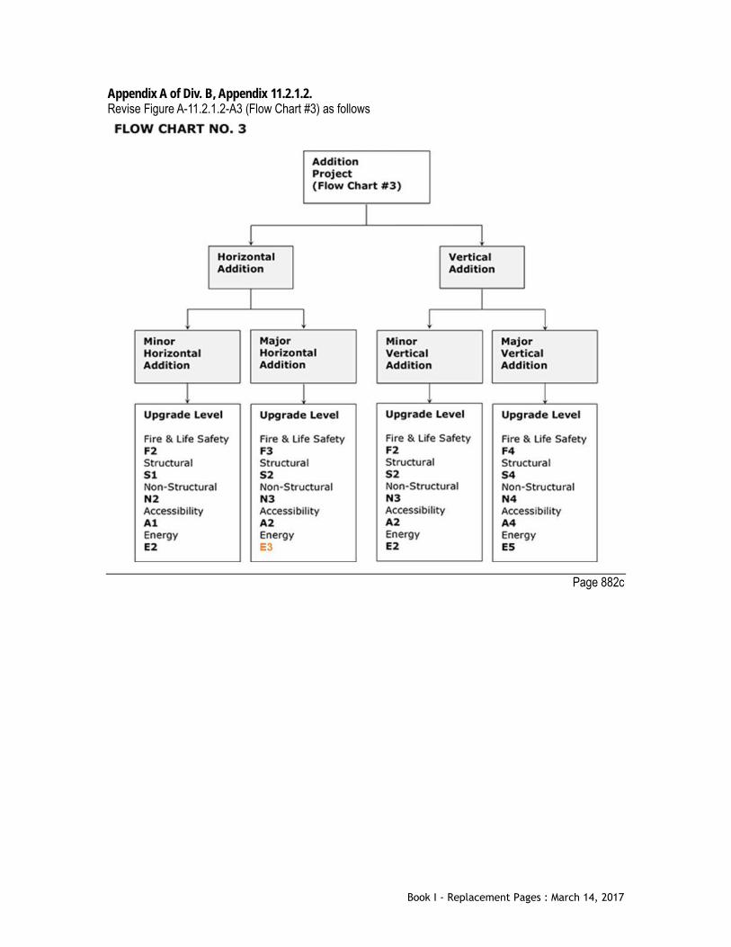
Appendix A of Div. B, Appendix 11.2.1.2. Revise Figure A-11.2.1.2-A3 (Flow Chart #3) as follows
Page 882c
Book I - Replacement Pages : March 14, 2017

[This page intentionally left blank]
Book I - Replacement Pages : March 14, 2017

Appendix A of Div. B, Appendix 11.2.1.2. Revised 3rd paragraph, of Step 3 - Procedure for Using the Upgrade Mechanism Model as follows The alternative acceptable solution for energy efficiency requires that the determined E design upgrade level is used to enter Table A-11.2.1.2.C to obtain a solution. The solution column in Table A-11.2.1.2.C provides the L level to enter Table A-11.2.1.2.D. Within the L Level row of Table A-11.2.1.2.D the user is provided with various Section rows under the Section column. Each Section row provides one or more alternative acceptable solutions under the Alternative Acceptable Solution Options column. Each alternative acceptable solution is identified as a separate numeric solution. There are one or more alternative acceptable solutions for each Section row. The “Select 1-L*” solution in Table A-11.2.1.2.C means that only one (1) of the alternative solutions in the Alternative Acceptable Solution Options column in Table A-11.2.1.2.D are required to meet the objective. It is up to the user to determine which Section(s) in the Section column and corresponding alternative acceptable solution in the Alternative Acceptable Solution Options column is (are) used to satisfy the objective. Within any 5 year period, when an alternative acceptable solution has been used previously within the project area, then that option is not permitted to be used as an alternative acceptable solution.
Page 884a
Book I - Replacement Pages : March 14, 2017
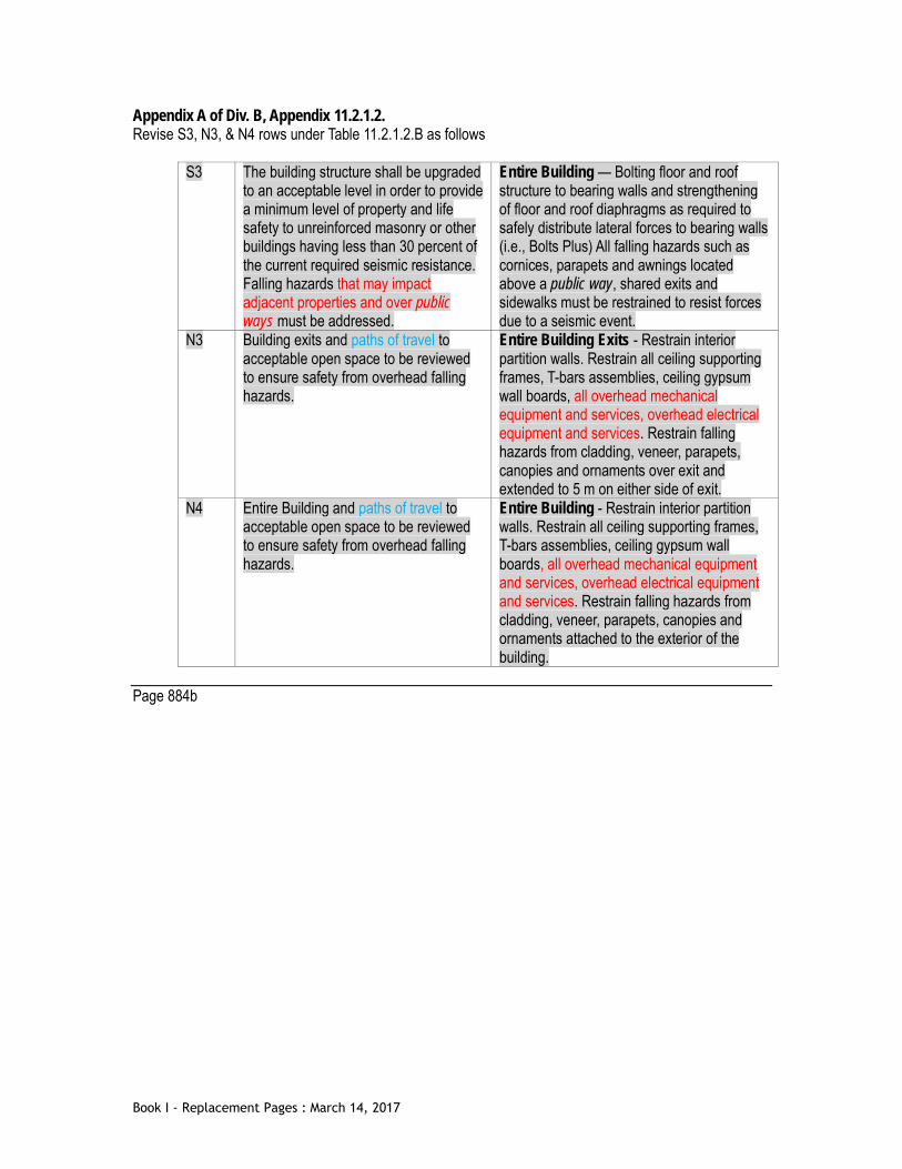
Appendix A of Div. B, Appendix 11.2.1.2. Revise S3, N3, & N4 rows under Table 11.2.1.2.B as follows
S3 The building structure shall be upgraded to an acceptable level in order to provide a minimum level of property and life safety to unreinforced masonry or other buildings having less than 30 percent of the current required seismic resistance. Falling hazards that may impact adjacent properties and over public ways must be addressed.
Entire Building — Bolting floor and roof structure to bearing walls and strengthening of floor and roof diaphragms as required to safely distribute lateral forces to bearing walls (i.e., Bolts Plus) All falling hazards such as cornices, parapets and awnings located above a public way, shared exits and sidewalks must be restrained to resist forces due to a seismic event.
N3 Building exits and paths of travel to acceptable open space to be reviewed to ensure safety from overhead falling hazards.
Entire Building Exits - Restrain interior partition walls. Restrain all ceiling supporting frames, T-bars assemblies, ceiling gypsum wall boards, all overhead mechanical equipment and services, overhead electrical equipment and services. Restrain falling hazards from cladding, veneer, parapets, canopies and ornaments over exit and extended to 5 m on either side of exit.
N4 Entire Building and paths of travel to acceptable open space to be reviewed to ensure safety from overhead falling hazards.
Entire Building - Restrain interior partition walls. Restrain all ceiling supporting frames, T-bars assemblies, ceiling gypsum wall boards, all overhead mechanical equipment and services, overhead electrical equipment and services. Restrain falling hazards from cladding, veneer, parapets, canopies and ornaments attached to the exterior of the building.
Page 884b
Book I - Replacement Pages : March 14, 2017

[This page intentionally left blank]
Book I - Replacement Pages : March 14, 2017

Appendix A of Div. B, Appendix 11.2.1.2. Revise note 1 of Table 11.2.1.2.C as follows (1) The solution column in Table A-11.2.1.2.C provides the solution that will satisfy the objective. The
solution column in Table A-11.2.1.2.C provides an L level to enter Table A-11.2.1.2.D. Within the L Level row the user is provided with various Section rows under the Section column. Each Section row provides one or more alternative acceptable solutions under the Alternative Acceptable Solutions Options column. Each alternative acceptable solution is identified as a separate numeric solution. There are one or more alternative acceptable solutions for each Section row. The “Select 1-L*” solution in Table A-11.2.1.2.C means that only one (1) of the alternative solutions in the Alternative Acceptable Solutions Options column in Table A-11.2.1.2.D are required to meet the objective. It is up to the user to determine which Section(s) in the Section column and corresponding alternative acceptable solution in the Alternative Acceptable Solution Option column is (are) used to satisfy the objective. Within any 5 year period, when an alternative acceptable solutions has been used previously within the project area, then that option is not permitted to be used as an alternative acceptable solution. a) the BOMA BESt certification is administered by BOMA, b) BOMA BESt Path 1 - BOMA BESt (Level 1, 2, 3, 4) provides proof of a valid Certification and ongoing commissioning per BOMA's BESt Practice Q.3 (Preventative Maintenance Program), and c) BOMA BESt Path 2 - BOMA BESt (Level 1-AL2, 2, 3, 4) provides proof of a first-time Certification (to at least Level 1 with an ASHRAE Level 2 audit) within the previous 18 months, or a valid Certification and an increase in BOMA BESt's Energy Performance Benchmark Scale by at least one level within the previous 18 months, or advancing Certification (from one level to another) within the previous 18 months.
Page 886b
Book I - Replacement Pages : March 14, 2017

Appendix A of Div. B, Appendix 11.2.1.2. Revise L2 HVAC Sub-row of Table 11.2.1.2.D as follows L2 HVAC(3) 1) Clean and Balance all Air Systems (per 6.7.2.3.2 of ASHRAE 90.1 - 2010)
2) Balance all Hydronic Systems (per 6.7.2.3.3 of ASHRAE 90.1 - 2010)
3) Remove Wood-Burning Fireplace unit
4) Replace gas fireplace pilot light with electronic ignition unit with energy rating over 50
5) Install makeup air supply per code to balance exhaust fan(s) over 300 cfm Page XXb Appendix A of Div. B, Appendix 11.2.1.2. Revise L2 Lighting Sub-row of Table 11.2.1.2.D as follows L2 Lighting 1) Upgrade to incorporate Automatic Lighting Shutoff (per 9.4.1.1 of ASHRAE 90.1 - 2010)
2) Upgrade to incorporate Space Control systems (per 9.4.1.2 of ASHRAE 90.1 - 2010)
3) Upgrade to control Parking Garage Lighting (per 9.4.1.3 of ASHRAE 90.1 - 2010)
4) Upgrade all Automatic Daylighting Controls for Primary Sidelighted Areas (per 9.4.1.4 of ASHRAE 90.1 - 2010)
5) Upgrade all Automatic Daylighting Controls for Toplighting (per 9.4.1.5 of ASHRAE 90.1 - 2010)
6) Upgrade to incorporate Additional Controls for specialized lighting (per 9.4.1.6 of ASHRAE 90.1 - 2010)
7) Exterior Lighting Control (per 9.4.1.7 of ASHRAE 90.1 - 2010)
8) Upgrade all hard wired lighting within scope of work area to High Efficiency light systems
9) Upgrade all hard wired lighting within an occupied space to High Efficiency light systems
10) Reduce total Skylight Fenestration/Glazing Area to 5% of gross roof area (per 5.5.4.2.2. of ASHRAE 90.1 - 2010)
Page 888a
Book I - Replacement Pages : March 14, 2017

Appendix A of Div. B, Appendix 11.2.1.2. Revise L3 Lighting Sub-row of Table 11.2.1.2.D as follows L3 Lighting 1) Provide a comprehensive Lighting System Assessment Report to be signed and sealed by
a design professional • Report to include: systems reviews, upgrade options, with estimates for energy
savings and cost paybacks.
2) Upgrade total Exterior Lighting Power (per 9.4.3 of ASHRAE 90.1 - 2010) of the building.
3) Meet the interior lighting power allowance by the Building Area Method (per 9.5 of ASHRAE 90.1 - 2010) of the suite.
4) Meet the interior lighting power allowance by the Space-by-Space Method (per 9.6 of ASHRAE 90.1 - 2010)
Page 888b
Book I - Replacement Pages : March 14, 2017

Appendix C of Div. B, Table C-4 [Add new table as follows]
Table C-4 Required Performance of Windows and Doors in Part 9 Buildings
Forming Part of Appendix C Location Climatic Data Specified Loads NAFS
1/5 DRWP
1/50 HWP
DRWP Wind Load Required Fenestration Performance
Pa kPA Pa Pa (psf) DP PG Water Resist.
Vancouver – Burnaby (Simon Fraser Univ.)
160 0.47 160 952 19.88 960 20 180
Vancouver – North Vancouver
160 0.45 160 911 19.03 960 20 180
Vancouver – Richmond 160 0.45 160 911 19.03 960 20 180 West Vancouver 160 0.48 160 972 20.30 1200 25 180
Page 918a
Book I - Replacement Pages : March 14, 2017

[This page intentionally left blank]
Book I - Replacement Pages : March 14, 2017

Appendix D of Div. B, 1.4.2.1.(2) Table D-1.1.2. [Replace Table D-1.1.2. as shown]
Table D-1.1.2. Documents Referenced in Appendix D Fire-Performance Ratings
Forming part of Sentence (1) Issuing Agency Document Number(1) Title of Document(2) Reference
ANSI A208.1-2009 Particleboard Table D-3.1.1.A. ASTM C 330-09 Lightweight Aggregates for Structural Concrete D-1.4.3.(2) ASTM C 1396/C 1396M-11 Gypsum Board D-1.5.1.
Table D-3.1.1.A. CCBFC NRCC 30629 Supplement to the National Building Code of Canada
1990 D-6.2. D-6.3. D-6.4.
CGSB 4-GP-36M-1978 Carpet Underlay, Fiber Type Table D-3.1.1.B. CGSB CAN/CGSB-4.129-97 Carpets for Commercial Use Table D-3.1.1.B. CGSB CAN/CGSB-11.3-M87 Hardboard Table D-3.1.1.A. CGSB CAN/CGSB-92.2-M90 Trowel or Spray Applied Acoustical Material D-2.3.4.(5) CSA A23.1-09/A23.2-09 Concrete Materials and Methods of Concrete
Construction/Test Methods and Standard Practices for Concrete
D-1.4.3.(1)
CSA CAN/CSA-A23.3-04 Design of Concrete Structures D-2.1.5.(2) D-2.6.6.(1) Table D-2.6.6.B. D-2.8.2.(1) Table D-2.8.2.
CSA A82.5-M1978 Structural Clay Non-Load-Bearing Tile Table D-2.6.1.A. CSA A82.22-M1977 Gypsum Plasters Table D-3.1.1.A. CSA CAN/CSA-A82.27-M91 Gypsum Board D-1.5.1.
Table D-3.1.1.A. CSA A82.30-M1980 Interior Furring, Lathing and Gypsum Plastering D-1.7.2.(1)
D-2.3.9.(1) Table D-2.5.1.
CSA A82.31-M1980 Gypsum Board Application D-2.3.9.(1) D-2.3.9.(6)
CSA CAN/CSA-A165.1-04 Concrete Block Masonry Units Table D-2.1.1. CSA O86-09 Engineering Design in Wood D-2.11.2.(1)
D-2.11.2.(2) CSA O121-08 Douglas Fir Plywood Table D-3.1.1.A. CSA O141-05 Softwood Lumber D-2.3.6.(2)
Table D-2.4.1. CSA O151-09 Canadian Softwood Plywood Table D-3.1.1.A. CSA O153-M1980 Poplar Plywood Table D-3.1.1.A. CSA CAN/CSA-O325-07 Construction Sheathing D-3.1.1.A. CSA O437.0-93 OSB and Waferboard Table D-3.1.1.A. CSA S16-09 Design of Steel Structures D-2.6.6.(1)
D-2.6.6.(3)
Book I - Replacement Pages : March 14, 2017

Table D-2.6.6.B. NFPA 80-2010 Fire Doors and Other Opening Protectives D-5.2.1.(1)
D-5.2.1.(2) ULC CAN/ULC-S101-07 Fire Endurance Tests of Building Construction and
Materials D-1.1.1.(4) D-1.12.1. D-2.3.2.
ULC CAN/ULC-S102-10 Test for Surface Burning Characteristics of Building Materials and Assemblies
D-1.1.1.(5)
ULC CAN/ULC-S102.2-10 Test for Surface Burning Characteristics of Flooring, Floor Coverings, and Miscellaneous Materials and Assemblies
D-1.1.1.(5) Table D-3.1.1.B.
ULC CAN/ULC-S114-05 Test for Determination of Non-Combustibility in Building Materials
D-1.1.1.(6) D-4.1.1.(1) D-4.2.1.
ULC ULC-S505-1974 Fusible Links for Fire Protection Service D-5.3.2. ULC CAN/ULC-S702-09 Mineral Fibre Thermal Insulation for Buildings Table D-2.3.4.A.
Table D-2.3.4.D. D-2.3.5.(2) D-2.3.5.(4) Table D-2.6.1.E. D-6.4.
ULC CAN/ULC-S703-09 Cellulose Fibre Insulation (CFI) for Buildings D-2.3.4.(5) ULC CAN/ULC-S706-09 Wood Fibre Thermal Insulation for Buildings Table D-3.1.1.A.
Notes to Table D-1.1.2.:
(1) Some documents may have been reaffirmed or reapproved. Check with the applicable issuing agency for up-to-date information.
(2) Some titles have been abridged to omit superfluous wording. Page 920d
Book I - Replacement Pages : March 14, 2017
Appendix D of Div. B, Appendix Note D-1.4.3. Description of Aggregates
2) Increasing the proportion of sand as fine aggregate in low density concretes requires increased thicknesses of material to produce equivalent fire-resistance ratings. Low density aggregates for Type L and Types L-S concretes used in loadbearing components shall conform to ASTM C 330/C 330M, “Lightweight Aggregates for Structural Concrete.”
Page 924a
Book I - Replacement Pages : March 14, 2017

[This page intentionally left blank]
Book I - Replacement Pages : March 14, 2017

Appendix D of Div. B, Appendix Note D-4.3.1. Typical Examples Noncombustible materials include brick, ceramic tile, concrete made from Portland cement with noncombustible aggregate, asbestos cement, plaster made from gypsum with noncombustible aggregate, metals commonly used in buildings, glass, granite, sandstone, slate, limestone and marble.
Page 956a
Book I - Replacement Pages : March 14, 2017

[This page intentionally left blank]
Book I - Replacement Pages : March 14, 2017

[This page intentionally left blank]
Book I - Replacement Pages : March 14, 2017

Div. B, Table 3.9.1.1. (Attribution Tables of Division B) [Insert in numerical sequence the following]
3.2.5.19. Radio Antennae Systems (1) [F12, F13 – OS1.2,OS1.5] [F12,F13 – OS3.7]
[F12, F13- OP1.2] Page 996b
Book I - Replacement Pages : March 14, 2017
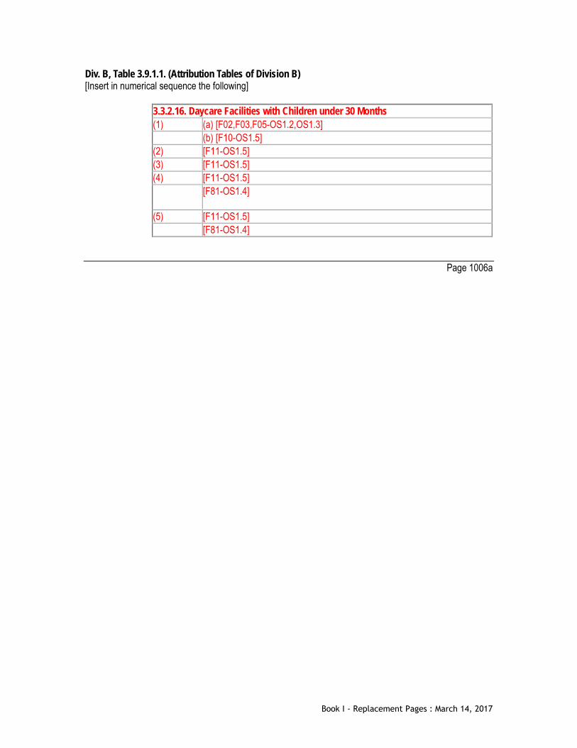
Div. B, Table 3.9.1.1. (Attribution Tables of Division B) [Insert in numerical sequence the following]
3.3.2.16. Daycare Facilities with Children under 30 Months (1) (a) [F02,F03,F05-OS1.2,OS1.3] (b) [F10-OS1.5] (2) [F11-OS1.5] (3) [F11-OS1.5] (4) [F11-OS1.5] [F81-OS1.4]
(5) [F11-OS1.5] [F81-OS1.4]
Page 1006a
Book I - Replacement Pages : March 14, 2017

[This page intentionally left blank]
Book I - Replacement Pages : March 14, 2017

[This page intentionally left blank]
Book I - Replacement Pages : March 14, 2017

Div. B, Table 3.9.1.1. (Attribution Tables of Division B) [Strikeout the following]
6.2.1.7. Outdoor Design Conditions (2) [F40,F44,F50-OH1.1] [F44-OS3.4]
Page 1048b
Book I - Replacement Pages : March 14, 2017
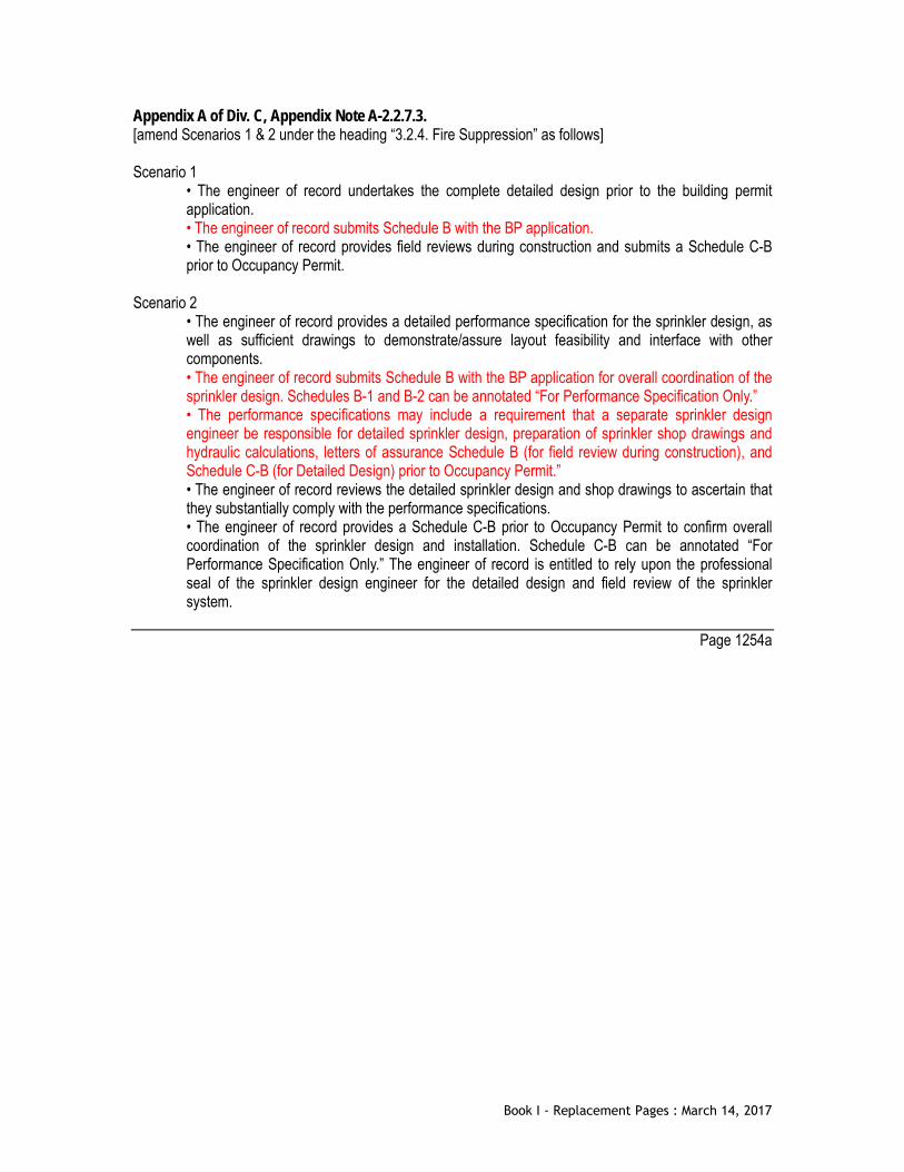
Appendix A of Div. C, Appendix Note A-2.2.7.3. [amend Scenarios 1 & 2 under the heading “3.2.4. Fire Suppression” as follows] Scenario 1
• The engineer of record undertakes the complete detailed design prior to the building permit application. • The engineer of record submits Schedule B with the BP application. • The engineer of record provides field reviews during construction and submits a Schedule C-B prior to Occupancy Permit.
Scenario 2
• The engineer of record provides a detailed performance specification for the sprinkler design, as well as sufficient drawings to demonstrate/assure layout feasibility and interface with other components. • The engineer of record submits Schedule B with the BP application for overall coordination of the sprinkler design. Schedules B-1 and B-2 can be annotated “For Performance Specification Only.” • The performance specifications may include a requirement that a separate sprinkler design engineer be responsible for detailed sprinkler design, preparation of sprinkler shop drawings and hydraulic calculations, letters of assurance Schedule B (for field review during construction), and Schedule C-B (for Detailed Design) prior to Occupancy Permit.” • The engineer of record reviews the detailed sprinkler design and shop drawings to ascertain that they substantially comply with the performance specifications. • The engineer of record provides a Schedule C-B prior to Occupancy Permit to confirm overall coordination of the sprinkler design and installation. Schedule C-B can be annotated “For Performance Specification Only.” The engineer of record is entitled to rely upon the professional seal of the sprinkler design engineer for the detailed design and field review of the sprinkler system.
Page 1254a
Book I - Replacement Pages : March 14, 2017

[This page intentionally left blank]
Book I - Replacement Pages : March 14, 2017