Building By law #11996: Book II (Plumbing) Insert Pages Set...
22
Replacement Pages: February 28, 2018 Building By-law #11996: Book II (Plumbing) - Insert Pages Set 3 Revision: February 28, 2018 Effective: January 1, 2018 Legend: Greybar text is Unique to Vancouver Red text are #11687 changes effective May 1, 2017. Blue text are errata to By-laws #11180 & #11687 . Green text are #11748 effective March 1, 2018 & #11776 effective January 1, 2018. Orange text are 11996 effective January 1, 2018. Struckout text is not to be read as part of the by-law, but is provided as an administrative convenience to show where a change has occurred. Instructions: Insert pages between successive pages as numbered (i.e. page 4a or 4b is inserted between pages 3 & 4). Specifics instructions may also be included after the header in [backets].
Transcript of Building By law #11996: Book II (Plumbing) Insert Pages Set...

Replacement Pages: February 28, 2018
Building By-law #11996: Book II (Plumbing) - Insert Pages Set 3 Revision: February 28, 2018 Effective: January 1, 2018
Legend: Greybar text is Unique to Vancouver Red text are #11687 changes effective May 1, 2017. Blue text are errata to By-laws #11180 & #11687 . Green text are #11748 effective March 1, 2018 & #11776 effective January 1, 2018. Orange text are 11996 effective January 1, 2018. Struckout text is not to be read as part of the by-law, but is provided as an administrative convenience to show where a change has occurred. Instructions: Insert pages between successive pages as numbered (i.e. page 4a or 4b is inserted between pages 3 & 4). Specifics instructions may also be included after the header in [backets].

Replacement Pages: February 28, 2018
[This page intentionally blank]

Replacement Pages: February 28, 2018
Div. B, Table T-1.3.1.2. [Replace Table 1.3.1.2 as follows]
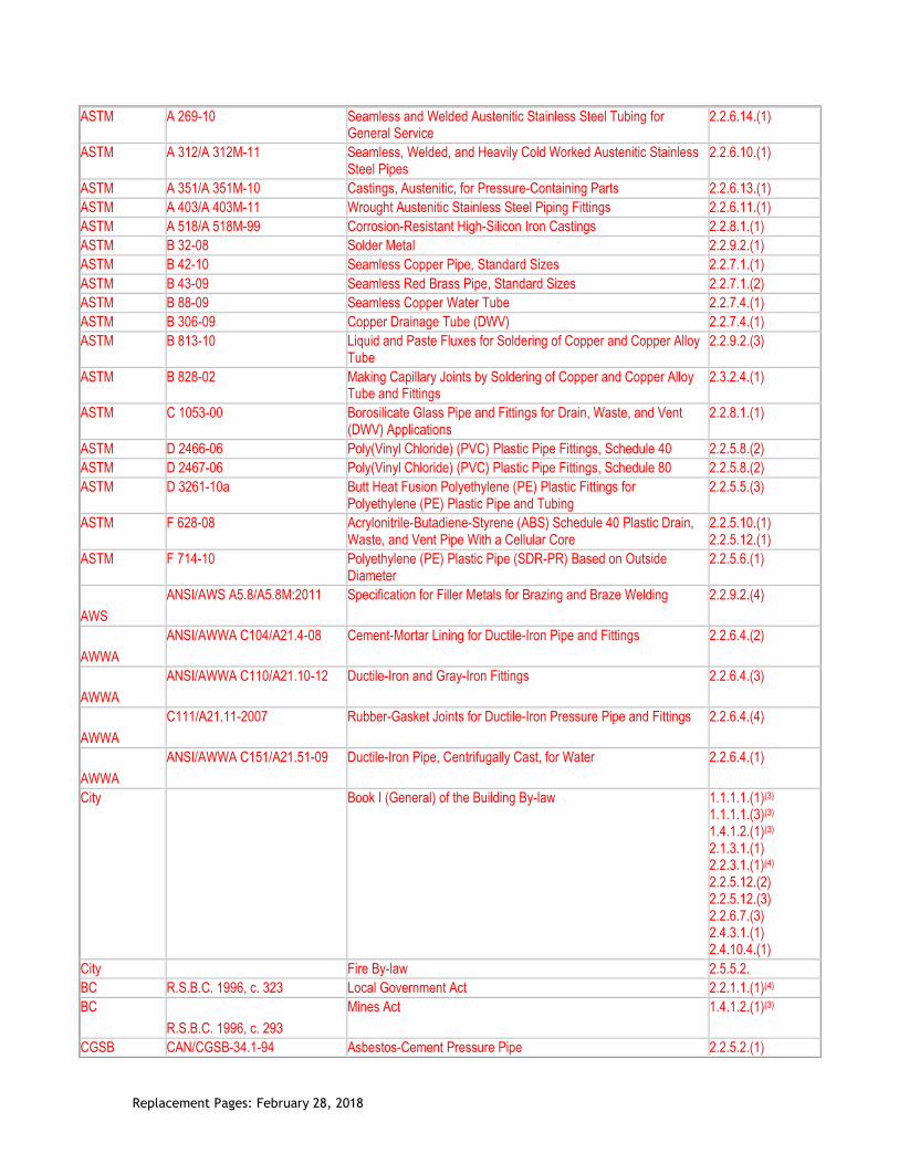
Table 1.3.1.2. Documents Referenced in Book II (Plumbing Systems) of the By-law
Forming part of Sentence 1.3.1.2.(1)
Issuing Agency
Document Number(1) Title of Document(2) By-law Reference
ANSI/AWWA C288-08 Stainless-Steel Pipe Flanges for Water Service — Sizes 2 In. Through 72 In. (50 mm Through 1,800 mm)
2.2.6.12.(1)
ANSI/CSA ANSI Z21.22-1999/ CSA 4.4-M99 (including Addenda 1 and 2)
Relief Valves for Hot Water Supply Systems 2.2.10.11.(1)
ASME/CSA ASME A112.18.1-2012/ CAN/CSA-B125.1-12
Plumbing Supply Fittings 2.2.10.6.(1) 2.2.10.7.(1)
ASME/CSA ASME A112.18.2-2011/ CAN/CSA-B125.2-11
Plumbing Waste Fittings 2.2.3.3.(1) 2.2.10.6.(2)
ASME/CSA ASME A112.19.1-08/ CSA B45.2-08
Enamelled Cast Iron and Enamelled Steel Plumbing Fixtures 2.2.2.2.(3) 2.2.2.2.(4)
ASME/CSA ASME A112.19.2-08/ CSA B45.1-08
Ceramic Plumbing Fixtures 2.2.2.2.(2)
ASME/CSA ASME A112.19.3-08/ CSA B45.4-08
Stainless Steel Plumbing Fixtures 2.2.2.2.(5)
ASME/CSA ASME A112.19.7-2012/ CSA B45.10-12
Hydromassage Bathtub Systems 2.2.2.2.(7)
ASME B16.3-2011 Malleable Iron Threaded Fittings, Classes 150 and 300 2.2.6.6.(1)
ASME B16.4-2011 Gray Iron Threaded Fittings, Classes 125 and 250 2.2.6.5.(1)
ASME B16.5-2009 Pipe Flanges and Flanged Fittings: NPS ½ Through NPS 24 Metric/Inch Standard
2.2.6.12.(1)
ASME B16.9-2007 Factory-Made Wrought Buttwelding Fittings 2.2.6.11.(1) 2.2.6.14.(1)
ASME B16.12-2009 Cast Iron Threaded Drainage Fittings 2.2.6.3.(1)
ASME B16.15-2011 Cast Copper Alloy Threaded Fittings, Classes 125 and 250 2.2.7.3.(1)
ASME B16.18-2012 Cast Copper Alloy Solder-Joint Pressure Fittings 2.2.7.6.(1) 2.2.7.6.(2)
ASME B16.22-2001 Wrought Copper and Copper Alloy Solder Joint Pressure Fittings 2.2.7.6.(1)
ASME B16.23-2011 Cast Copper Alloy Solder Joint Drainage Fittings: DWV 2.2.7.5.(1)
ASME B16.24-2011 Cast Copper Alloy Pipe Flanges and Flanged Fittings: Classes 150, 300, 600, 900, 1500, and 2500
2.2.7.2.(1)
ASME B16.26-2011 Cast Copper Alloy Fittings for Flared Copper Tubes 2.2.7.7.(1) 2.2.7.7.(2)
ASME B16.29-2007 Wrought Copper and Wrought Copper Alloy Solder-Joint Drainage Fittings – DWV
2.2.7.5.(1)
ASME B31.9-2008 Building Services Piping 2.3.2.8.(1)
ASME B36.19M-2004 Stainless Steel Pipe 2.2.6.10.(1)
ASSE ANSI/ASSE 1010-2004 Water Hammer Arresters 2.2.10.15.(1)
ASSE 1051-2009G Individual and Branch Type Air Admittance Valves for Sanitary Drainage Systems
2.2.10.16.(1)
ASTM A 53/A 53M-10 Pipe, Steel, Black and Hot-Dipped, Zinc-Coated, Welded and Seamless
2.2.6.7.(4)
ASTM A 182/A 182M-06 Forged or Rolled Alloy and Stainless Steel Pipe Flanges, Forged Fittings, and Valves and Parts for High-Temperature Service
2.2.6.12.(1) 2.2.6.13.(1)
Replacement Pages: February 28, 2018
ASTM A 269-10 Seamless and Welded Austenitic Stainless Steel Tubing for General Service
2.2.6.14.(1)
ASTM A 312/A 312M-11 Seamless, Welded, and Heavily Cold Worked Austenitic Stainless Steel Pipes
2.2.6.10.(1)
ASTM A 351/A 351M-10 Castings, Austenitic, for Pressure-Containing Parts 2.2.6.13.(1)
ASTM A 403/A 403M-11 Wrought Austenitic Stainless Steel Piping Fittings 2.2.6.11.(1)
ASTM A 518/A 518M-99 Corrosion-Resistant High-Silicon Iron Castings 2.2.8.1.(1)
ASTM B 32-08 Solder Metal 2.2.9.2.(1)
ASTM B 42-10 Seamless Copper Pipe, Standard Sizes 2.2.7.1.(1)
ASTM B 43-09 Seamless Red Brass Pipe, Standard Sizes 2.2.7.1.(2)
ASTM B 88-09 Seamless Copper Water Tube 2.2.7.4.(1)
ASTM B 306-09 Copper Drainage Tube (DWV) 2.2.7.4.(1)
ASTM B 813-10 Liquid and Paste Fluxes for Soldering of Copper and Copper Alloy Tube
2.2.9.2.(3)
ASTM B 828-02 Making Capillary Joints by Soldering of Copper and Copper Alloy Tube and Fittings
2.3.2.4.(1)
ASTM C 1053-00 Borosilicate Glass Pipe and Fittings for Drain, Waste, and Vent (DWV) Applications
2.2.8.1.(1)
ASTM D 2466-06 Poly(Vinyl Chloride) (PVC) Plastic Pipe Fittings, Schedule 40 2.2.5.8.(2)
ASTM D 2467-06 Poly(Vinyl Chloride) (PVC) Plastic Pipe Fittings, Schedule 80 2.2.5.8.(2)
ASTM D 3261-10a Butt Heat Fusion Polyethylene (PE) Plastic Fittings for Polyethylene (PE) Plastic Pipe and Tubing
2.2.5.5.(3)
ASTM F 628-08 Acrylonitrile-Butadiene-Styrene (ABS) Schedule 40 Plastic Drain, Waste, and Vent Pipe With a Cellular Core
2.2.5.10.(1) 2.2.5.12.(1)
ASTM F 714-10 Polyethylene (PE) Plastic Pipe (SDR-PR) Based on Outside Diameter
2.2.5.6.(1)
AWS
ANSI/AWS A5.8/A5.8M:2011 Specification for Filler Metals for Brazing and Braze Welding 2.2.9.2.(4)
AWWA
ANSI/AWWA C104/A21.4-08 Cement-Mortar Lining for Ductile-Iron Pipe and Fittings 2.2.6.4.(2)
AWWA
ANSI/AWWA C110/A21.10-12 Ductile-Iron and Gray-Iron Fittings 2.2.6.4.(3)
AWWA
C111/A21.11-2007 Rubber-Gasket Joints for Ductile-Iron Pressure Pipe and Fittings 2.2.6.4.(4)
AWWA
ANSI/AWWA C151/A21.51-09 Ductile-Iron Pipe, Centrifugally Cast, for Water 2.2.6.4.(1)
City Book I (General) of the Building By-law 1.1.1.1.(1)(3) 1.1.1.1.(3)(3) 1.4.1.2.(1)(3) 2.1.3.1.(1) 2.2.3.1.(1)(4) 2.2.5.12.(2) 2.2.5.12.(3) 2.2.6.7.(3) 2.4.3.1.(1) 2.4.10.4.(1)
City Fire By-law 2.5.5.2.
BC R.S.B.C. 1996, c. 323 Local Government Act 2.2.1.1.(1)(4)
BC
R.S.B.C. 1996, c. 293
Mines Act 1.4.1.2.(1)(3)
CGSB CAN/CGSB-34.1-94 Asbestos-Cement Pressure Pipe 2.2.5.2.(1)

Replacement Pages: February 28, 2018
CGSB CAN/CGSB-34.9-94 Asbestos-Cement Sewer Pipe 2.2.5.1.(2)
CGSB CAN/CGSB-34.22-94 Asbestos-Cement Drain Pipe 2.2.5.1.(1)
CGSB CAN/CGSB-34.23-94 Asbestos-Cement House Connection Sewer Pipe 2.2.5.1.(2)
CSA A60.1-M1976 Vitrified Clay Pipe 2.2.5.4.(1)
CSA A60.3-M1976 Vitrified Clay Pipe Joints 2.2.5.4.(2)
CSA CAN/CSA-A257.1-09 Non-Reinforced Circular Concrete Culvert, Storm Drain, Sewer Pipe, and Fittings
2.2.5.3.(1)
CSA CAN/CSA-A257.2-09 Reinforced Circular Concrete Culvert, Storm Drain, Sewer Pipe, and Fittings
2.2.5.3.(1)
CSA CAN/CSA-A257.3-09 Joints for Circular Concrete Sewer and Culvert Pipe, Manhole Sections, and Fittings Using Rubber Gaskets
2.2.5.3.(2)
CSA CAN/CSA-A257.4-09 Precast Reinforced Circular Concrete Manhole Sections, Catch Basins, and Fittings
2.2.5.3.(5)
CSA CAN/CSA-B45 Series-02 Plumbing Fixtures 2.2.2.2.(1)
CSA CSA-B45.5-11/IAPMO Z124-2011
Plastic Plumbing Fixtures 2.2.2.2.(6)
CSA CAN/CSA-B45.9-02 Macerating Systems and Related Components 2.2.2.2.(8)
CSA B64.0-11 Definitions, General Requirements, and Test Methods for Vacuum Breakers and Backflow Preventers
2.2.10.10.(1)
CSA CAN/CSA-B64.1.1-11 Atmospheric Vacuum Breakers (AVB) 2.2.10.10.(1)
CSA CAN/CSA-B64.1.2-11 Pressure Vacuum Breakers (PVB) 2.2.10.10.(1)
CSA B64.2-11 Hose Connection Vacuum Breakers (HCVB) 2.2.10.10.(1)
CSA B64.2.1-11 Hose Connection Vacuum Breakers (HCVB) with Manual Draining Feature
2.2.10.10.(1)
CSA B64.2.2-11 Hose Connection Vacuum Breakers (HCVB) with Automatic Draining Feature
2.2.10.10.(1)
CSA B64.3-11 Dual Check Valve Backflow Preventers with Atmospheric Port (DCAP)
2.2.10.10.(1)
CSA B64.4-11 Reduced Pressure Principle Backflow Preventers (RP) 2.2.10.10.(1)
CSA B64.4.1-11 Reduced Pressure Principle Backflow Preventers for Fire Protection Systems (RPF)
2.6.2.4.(2) 2.6.2.4.(4)
CSA B64.5-11 Double Check Valve Backflow Preventers (DCVA) 2.2.10.10.(1)
CSA B64.5.1-11 Double Check Valve Backflow Preventers for Fire Protection Systems (DCVAF)
2.6.2.4.(2)
CSA B64.6-11 Dual Check Valve Backflow Preventers (DuC) 2.2.10.10.(1)
CSA B64.6.1-11 Dual Check Valve Backflow Preventers for Fire Protection Systems (DuCF)
2.6.2.4.(2)
CSA B64.7-11 Laboratory Faucet Vacuum Breakers (LFVB) 2.2.10.10.(1)
CSA B64.8-11 Dual Check Valve Backflow Preventers with Intermediate Vent (DuCV)
2.2.10.10.(1)
CSA B64.9-11 Single Check Valve Backflow Preventers for Fire Protection Systems (SCVAF)
2.6.2.4.(2)
CSA B64.10-11 Selection and Installation of Backflow Preventers 2.6.2.1.(3)
CSA B70-12 Cast Iron Soil Pipe, Fittings, and Means of Joining 2.2.6.1.(1) 2.4.6.4.(2)
CSA B125.3-12 Plumbing Fittings 2.2.10.6.(1) 2.2.10.6.(3) 2.2.10.7.(2) 2.2.10.10.(2)
CSA CAN/CSA-B127.1-99 Asbestos Cement Drain, Waste and Vent Pipe and Pipe Fittings 2.2.5.1.(1) 2.2.6.2.(1)
CSA B127.2-M1977 Components for Use in Asbestos Cement Building Sewer Systems 2.2.5.1.(2)

Replacement Pages: February 28, 2018
2.2.6.2.(1)
CSA CAN/CSA-B128.1-06 Design and Installation of Non-Potable Water Systems 2.7.4.1.(1)
CSA CAN/CSA-B137.1-09 Polyethylene (PE) Pipe, Tubing, and Fittings for Cold-Water Pressure Services
2.2.5.5.(1)
CSA CAN/CSA-B137.2-09 Polyvinylchloride (PVC) Injection-Moulded Gasketed Fittings for Pressure Applications
2.2.5.8.(3)
CSA CAN/CSA-B137.3-09 Rigid Polyvinylchloride (PVC) Pipe and Fittings for Pressure Applications
2.2.5.8.(1)
CSA CAN/CSA-B137.5-09 Crosslinked Polyethylene (PEX) Tubing Systems for Pressure Applications
2.2.5.7.(1)
CSA CAN/CSA-B137.6-09 Chlorinated Polyvinylchloride (CPVC) Pipe, Tubing, and Fittings for Hot- and Cold-Water Distribution Systems
2.2.5.9.(1)
CSA CAN/CSA-B137.9-09 Polyethylene/Aluminum/Polyethylene (PE-AL-PE) Composite Pressure-Pipe Systems
2.2.5.13.(1)
CSA CAN/CSA-B137.10-09 Crosslinked Polyethylene/Aluminum/Crosslinked Polyethylene (PEX-AL-PEX) Composite Pressure-Pipe Systems
2.2.5.13.(4) 2.2.5.14.(1)
CSA CAN/CSA-B137.11-09 Polypropylene (PP-R) Pipe and Fittings for Pressure Applications 2.2.5.15.(1)
CSA B158.1-1976 Cast Brass Solder Joint Drainage, Waste and Vent Fittings 2.2.10.1.(1)
CSA CAN/CSA-B181.1-11 Acrylonitrile-Butadiene-Styrene (ABS) Drain, Waste, and Vent Pipe and Pipe Fittings
2.2.5.10.(1) 2.2.5.11.(1) 2.2.5.12.(1) 2.4.6.4.(2)
CSA CAN/CSA-B181.2-11 Polyvinylchloride (PVC) and Chlorinated Polyvinylchloride (CPVC) Drain, Waste, and Vent Pipe and Pipe Fittings
2.2.5.10.(1) 2.2.5.11.(1) 2.2.5.12.(1) 2.4.6.4.(2)
CSA CAN/CSA-B181.3-11 Polyolefin and Polyvinylidene Fluoride (PVDF) Laboratory Drainage Systems
2.2.8.1.(1)
CSA CAN/CSA-B182.1-11 Plastic Drain and Sewer Pipe and Pipe Fittings 2.2.5.10.(1) 2.4.6.4.(2)
CSA CAN/CSA-B182.2-11 PSM Type Polyvinylchloride (PVC) Sewer Pipe and Fittings 2.2.5.10.(1)
CSA CAN/CSA-B182.4-11 Profile Polyvinylchloride (PVC) Sewer Pipe and Fittings 2.2.5.10.(1)
CSA CAN/CSA-B182.6-11 Profile Polyethylene (PE) Sewer Pipe and Fittings For Leak-Proof Sewer Applications
2.2.5.10.(1)
CSA B242-05 Groove- and Shoulder-Type Mechanical Pipe Couplings 2.2.10.4.(1)
CSA B272-93 Prefabricated Self-Sealing Roof Vent Flashings 2.2.10.14.(2)
CSA CAN/CSA-B356-10 Water Pressure Reducing Valves for Domestic Water Supply Systems
2.2.10.12.(1)
CSA CAN/CSA-B602-10 Mechanical Couplings for Drain, Waste, and Vent Pipe and Sewer Pipe
2.2.10.4.(2)
CSA CAN/CSA-F379.1 Series-09 (excluding CAN/CSA-F379S1-11)
Packaged Solar Domestic Hot Water Systems (Liquid to Liquid Heat Transfer)
2.2.10.13.(1)
CSA CAN/CSA-F383-08 Installation Code for Solar Domestic Hot Water Systems 2.6.1.8.(1)
CSA CAN/CSA-G401-071 Corrugated Steel Pipe Products 2.2.6.8.(1)
NFPA 13D-2010 Installation of Sprinkler Systems in One- and Two-Family Dwellings and Manufactured Homes
2.6.3.1.(3)
NSF/ANSI 61 – 2016 Drinking Water System Components – Health Effects 2.2.6.10.
NSF/ANSI 372 - 2016 Drinking Water System Components – Lead Content 2.2.6.11., 2.2.6.12., 2.2.6.13.
ULC CAN/ULC-S114-05 Test for Determination of Non-Combustibility in Building Materials 1.4.1.2.(1) (3)

Replacement Pages: February 28, 2018
Notes to Table 1.3.1.2.: (1) Some documents may have been reaffirmed or reapproved. Check with the applicable issuing agency for up-to-date information. (2) Some titles have been abridged to omit superfluous wording. (3) By-law reference is in Division A. (4) By-law reference is in Division C.
Page 48e

Replacement Pages: February 28, 2018
Div. B, Table T-1.3.1.2. [Replace Table 1.3.1.2 - see page over]
Page 48f

Replacement Pages: February 28, 2018
Div. B, 2.2.6. Ferrous Pipes and Fittings [Add new Articles as follows] 2.2.6.10. Stainless Steel Pipe
1) Stainless steel pipe shall conform to a) ASTM A 312/A 312M, “Seamless, Welded, and Heavily Cold Worked Austenitic Stainless Steel Pipes,” b) ASME B36.19M, “Stainless Steel Pipe,” and c) NSF/ANSI 61 “Drinking Water System Components – Health Effects.”
2) Only grade 304/304L or 316/316L stainless steel pipe shall be used.
2.2.6.11. Stainless Steel Butt Weld Pipe Fittings
1) Stainless steel butt weld pipe fittings shall conform to a) ASTM A 403/A 403M, “Wrought Austenitic Stainless Steel Piping Fittings,” b) ASME B16.9 “Factory-Made Wrought Buttwelding Fittings,” and c) NSF/ANSI 372 “Drinking Water System Components – Led Content.”
2) Stainless steel butt weld pipe fittings shall be made of a material that matches the grade of the pipe material used.
2.2.6.12. Stainless Steel Pipe Flanges
1) Stainless steel pipe flanges shall conform to a) ASME B16.5, “Pipe Flanges and Flanged Fittings: NPS ½ Through NPS 24 Metric/Inch Standard,” b) NSF/ANSI 372 “Drinking Water System Components – Led Content,” and c) shall conform with
i)ASTM A 182/A 182M, “Forged or Rolled Alloy and Stainless Steel Pipe Flanges, Forged Fittings, and Valves and Parts for High-Temperature Service,” or ii) ANSI/AWWA C228, “Stainless-Steel Pipe Flanges for Water Service — Sizes 2 In. Through 72 In. (50 mm Through 1,800 mm).”
2) Stainless steel pipe flanges shall be made of a material that matches the grade of the pipe material used.
[continued on next page]
Page 64a

Replacement Pages: February 28, 2018
Div. B, 2.2.6. Ferrous Pipes and Fittings [Add new Articles as follows] 2.2.6.13. Stainless Steel Threaded Fittings
1) Stainless steel threaded fittings shall be schedule 40s or greater conforming to NSF/ANSI 372 “Drinking Water System Components – Led Content,” and
a) ASTM A 182/A 182M, “Forged or Rolled Alloy and Stainless Steel Pipe Flanges, Forged Fittings, and Valves and Parts for High-Temperature Service,” or b) ASTM A 351/A 351M, “Castings, Austenitic, for Pressure-Containing Parts.”
2) Stainless steel threaded fittings shall be made of a material that matches the grade of the pipe material used.
2.2.6.14. Stainless Steel Tube
1) Stainless steel tube shall conform to a) ASTM A 269, “Seamless and Welded Austenitic Stainless Steel Tubing for General Service,” and b) ASME B16.9, “Factory-Made Wrought Buttwelding Fittings.”
2) Only grade 304/304L or 316/316L stainless steel tube shall be used.
2.2.6.15. Stainless Steel Pipe and Tube
1) The use of stainless steel pipe and tube shall conform to Table 2.2.6.15.
Table 2.2.6.15. Permitted Uses of Stainless Steel Tube and Pipe
Forming part of Sentence 2.2.6.15.(1)
Stainless Steel Tube or Pipe
Plumbing Purposes
Water Distribution System
Building Sewer
Drainage System Venting System
Under-ground
Above-ground
Under-ground
Above-ground
Under-ground
Above-ground
Stainless steel pipe P P P P P P P
Stainless steel tube P P N N N N N
P = Permitted N = Not Permitted
Div. B, 2.2.9.2. Solders and Fluxes
4) Brazing alloys shall conform to ANSI/AWS A5.8, “Specification for Filler Metals for Brazing and Braze Welding,” BCuP range.
Page 64b

Replacement Pages: February 28, 2018
Div. B, 2.2.10.6.Supply and Waste Fittings
1) Supply fittings shall conform to a) ASME A112.18.1/CSA B125.1, “Plumbing Supply Fittings,” or b) CSA B125.3, “Plumbing Fittings.” 2) Waste fittings shall conform to ASME A112.18.2/CSA B125.2, “Plumbing Waste Fittings.” 3) Supply fittings complying with Sentence (1) shall have a maximum flow rate in compliance with Book I Division B Article 10.3.1.2.
Div. B, 2.2.10.7. Water Temperature Control
1) Except as provided in Sentence (2), all valves supplying fixed-location shower heads shall be
individual pressure‑balanced or thermostatic-mixing valves conforming to ASME A112.18.1/CSA
B125.1, “Plumbing Supply Fittings.” 2) Individual pressure-balanced or thermostatic-mixing valves shall not be required for showers having a single tempered water supply that is controlled by a master thermostatic-mixing valve conforming to CSA B125.3, “Plumbing Fittings.” 3) All mixing valves supplying shower heads shall be of the pressure-balanced, thermostatic, or combination pressure-balanced/thermostatic type capable of a) maintaining a water outlet temperature that does not exceed 49°C, and b) limiting thermal shock. 4) The temperature of water discharging into a bathtub shall not exceed 49°C.
Div. B, 2.2.10.10. Back-Siphonage Preventers and Backflow Preventers [see next page]
Page 66a

Replacement Pages: February 28, 2018
Div. B, 2.2.10.10. Back-Siphonage Preventers and Backflow Preventers
1) Except as provided in Sentence (2), back-siphonage preventers and backflow preventers shall conform to a) CSA B64.0, “Definitions, General Requirements, and Test Methods for Vacuum Breakers and Backflow Preventers,” b) CSA B64.1.1, “Atmospheric Vacuum Breakers (AVB),” c) CSA B64.1.2, “Pressure Vacuum Breakers (PVB),” d) CSA B64.2, “Hose Connection Vacuum Breakers (HCVB),” e) CSA B64.2.1, “Hose Connection Vacuum Breakers (HCVB) with Manual Draining Feature,” f) CSA B64.2.2, “Hose Connection Vacuum Breakers (HCVB) with Automatic Draining Feature,” g) CSA B64.3, “Dual Check Valve Backflow Preventers with Atmospheric Port (DCAP),” h) CSA B64.4, “Reduced Pressure Principle Backflow Preventers (RP),” i) CSA B64.5, “Double Check Valve (DCVA) Backflow Preventers,” j) CSA B64.6, “Dual Check Valve (DuC) Backflow Preventers,” k) CSA B64.7, “Laboratory Faucet Vacuum Breakers (LFVB),” or l) CSA B64.8, “Dual Check Valve Backflow Preventers with Intermediate Vent (DuCV).” 2) Back-siphonage preventers for tank-type water closets (anti-siphon fill valves) shall conform to CSA B125.3, “Plumbing Fittings.”
Div. B, 2.2.10.13. Solar Domestic Hot Water
1) Equipment for solar heating of potable water shall conform to CAN/CSA-F379 Series, “Packaged Solar Domestic Hot Water Systems (Liquid-to-Liquid Heat Transfer),” excluding CAN/CSA-F379S1.
Div. B, 2.2.10.16. Air Admittance Valves
1) Air admittance valves shall conform to ASSE 1051, “Individual and Branch Type Air Admittance Valves (AAVs) for Sanitary Drainage Systems.” (See Appendix A.)
Page 66b

Replacement Pages: February 28, 2018
Div. B, 2.6.1.8. Solar Domestic Hot Water Systems
1) Systems for solar heating of potable water shall be installed in conformance with CAN/CSA-F383 “Installation of Packaged Solar Domestic Hot Water Systems.”
Div. B, 2.6.2.1.(3) Connection of Systems [Replace Sentences (3) & (4) with the following]
3) Backflow preventers shall be selected, installed, maintained and field tested in conformance with the Water Works By-law. 4) Backflow preventers shall be maintained and field tested in conformance with the Water Works By-law.
Page 98a

Replacement Pages: February 28, 2018
[This page intentionally blank]
Page 98b

Replacement Pages: February 28, 2018
Appendix A of Div. B, Appendix Note A-2.2.10.4.(1) [insert the following new note before A-2.2.10.5.(1)] A-2.2.10.4.(1) Fittings in Pressure Piping Applications Piping used in pressure applications are to be grooved and constructed using tools specifically designed for that piping material. It is important that all groove profiles are to meet the fitting manufacturer’s guidelines and conform to CSA-B242 “Groove and Shoulder-Type Mechanical Pipe Couplings.” Overly shallow roll grooved or cut connections may result in reduced working pressures at the joint or the failure of the connection due to insufficient engagement of the coupling or from slippage at the joint. Conversely, grooves or cuts that are overly deep may result in failures of the pipe stemming from corrosion or stress concentrations at the joints.
Incorrect Correct
Note: Image is exaggerated for clarity
Figure A-2.2.10.4.(1) Insufficient Key Engagement of Fitting in Roll Grooved Connection
Page 140a

Replacement Pages: February 28, 2018
[This page intentionally blank]
Page 140b
Replacement Pages: February 28, 2018
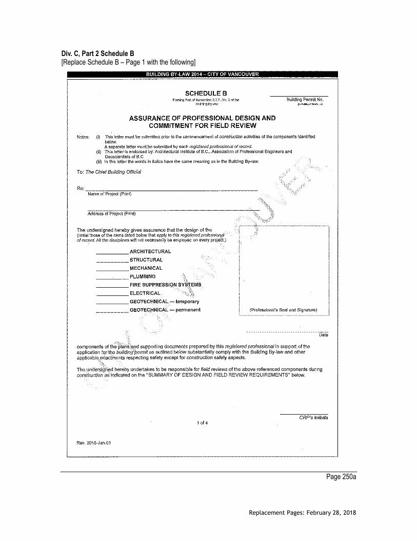
Div. C, Part 2 Schedule B [Replace Schedule B – Page 1 with the following]
Page 250a
Replacement Pages: February 28, 2018
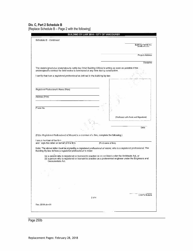
Div. C, Part 2 Schedule B [Replace Schedule B – Page 2 with the following]
Page 250b

Replacement Pages: February 28, 2018
Div. C, Part 2 Schedule B [Replace Schedule B – Page 3 with the following]
Page 250c

Replacement Pages: February 28, 2018
Div. C, Part 2 Schedule B [Replace Schedule B – Page 4 with the following]
Page 250d

Replacement Pages: February 28, 2018
Div. C, Part 2 Schedule C-A [Replace Schedule C-A with the following]
Page 254a

Replacement Pages: February 28, 2018
[This page intentionally left blank]
Page 254b