Building Automation System (BAS) for HVAC
20
U OF I FACILITIES STANDARDS 23 09 23- 1 BUILDING AUTOMATION SYSTEM ADDENDUM NO. 2 (BAS) FOR HVAC REVISED SECTION LAST UPDATED NOVEMBER 1, 2011 SECTION 23 09 23 - BUILDING AUTOMATION SYSTEM (BAS) FOR HVAC PART I - GENERAL 1.1 SECTION INCLUDES A. Standalone Digital Controllers B. Network Interface Modules C. Application Specific Controllers D. Integrating Subsystem Controllers E. Control Devices, Components, Wiring and Materi al F. Instructions for Owners 1.2 RELATED SECTIONS [Note to AE: List additional sections as required by project.] A. Section 01 91 13 - General Commissioning Requirements B. Section 23 08 00 - Commissioning of HVAC C. Section 23 09 13 - Instrumentation and Control Devices for HVAC D. Section 23 09 13.33 – Control Valves E. Section 23 09 13.34 – Control Valve Actuators F. Section 23 09 13.43 – Control Dampers G. Section 28 30 00 - Fire and Smoke Detection System 1.3 RELATED DRAWINGS [Note to AE: Include as appropriate and edit to be specific to the project.] A. Drawing 23 09 05-01, Controls Symbols B. Drawing 23 09 05-02, Type VAV AHU, Minimum OA, Steam Preheat C. Drawing 23 09 05-03, Type VAV AHU, Minimum OA, HW Preheat D. Drawing 23 09 05-04, Type CV AHU, Minimum OA, Steam Preheat E. Drawing 23 09 05-05, Type CV AHU, Minimum OA, HW Preheat F. Drawing 23 09 05-06, Type CV AHU, 100%OA, Steam Preheat G. Drawing 23 09 05-07, Type CV AHU,100%OA,HW Preheat H. Drawing 23 09 05-08, Type CV AHU,100%OA,HW Preheat, Heat Recovery Loop I. Drawing 23 09 05-09, Type CV AHU,100%OA,HW Preheat, Heat Wheel J. Drawing 23 09 05-10, Pressure Independent VAV Box with HW Reheat and Perimeter Radiation K. Drawing 23 09 05-11, Steam to Hot Water Heat Exchanger HW System Controls L. Drawing 23 09 05-12, Chilled Water Bldg Entrance Valve Flow Control Valve M. Drawing 23 09 13-1, Pressure Differential Instrumentation Piping N. Drawing 23 09 13-2, Static Pressure Instrumentation Detail O. Drawing 23 09 13-3, Central Chilled Water System Metering Station Detail P. Drawing 23 09 23-1, 40 Deg Freezestat-Elect CHW Valve Override
Transcript of Building Automation System (BAS) for HVAC

7/31/2019 Building Automation System (BAS) for HVAC
http://slidepdf.com/reader/full/building-automation-system-bas-for-hvac 1/20
U OF I FACILITIES STANDARDS 23 09 23- 1 BUILDING AUTOMATION SYSTEM ADDENDUM NO. 2 (BAS) FOR HVACREVISED SECTION LAST UPDATED NOVEMBER 1, 2011
SECTION 23 09 23 - BUILDING AUTOMATION SYSTEM (BAS) FOR HVAC
PART I - GENERAL
1.1 SECTION INCLUDES
A. Standalone Digital ControllersB. Network Interface Modules
C. Application Specific Controllers
D. Integrating Subsystem Controllers
E. Control Devices, Components, Wiring and Material
F. Instructions for Owners
1.2 RELATED SECTIONS [Note to AE: List additional sections as required by project.]
A. Section 01 91 13 - General Commissioning Requirements
B. Section 23 08 00 - Commissioning of HVAC
C. Section 23 09 13 - Instrumentation and Control Devices for HVAC D. Section 23 09 13.33 – Control Valves
E. Section 23 09 13.34 – Control Valve Actuators
F. Section 23 09 13.43 – Control Dampers
G. Section 28 30 00 - Fire and Smoke Detection System
1.3 RELATED DRAWINGS [Note to AE: Include as appropriate and edit to be specific to the project.]
A. Drawing 23 09 05-01, Controls Symbols
B. Drawing 23 09 05-02, Type VAV AHU, Minimum OA, Steam Preheat
C. Drawing 23 09 05-03, Type VAV AHU, Minimum OA, HW Preheat
D. Drawing 23 09 05-04, Type CV AHU, Minimum OA, Steam Preheat
E. Drawing 23 09 05-05, Type CV AHU, Minimum OA, HW Preheat
F. Drawing 23 09 05-06, Type CV AHU, 100%OA, Steam Preheat
G. Drawing 23 09 05-07, Type CV AHU,100%OA,HW Preheat
H. Drawing 23 09 05-08, Type CV AHU,100%OA,HW Preheat, Heat Recovery Loop
I. Drawing 23 09 05-09, Type CV AHU,100%OA,HW Preheat, Heat Wheel
J. Drawing 23 09 05-10, Pressure Independent VAV Box with HW Reheat and Perimeter Radiation
K. Drawing 23 09 05-11, Steam to Hot Water Heat Exchanger HW System Controls
L. Drawing 23 09 05-12, Chilled Water Bldg Entrance Valve Flow Control Valve
M. Drawing 23 09 13-1, Pressure Differential Instrumentation Piping
N. Drawing 23 09 13-2, Static Pressure Instrumentation Detail
O. Drawing 23 09 13-3, Central Chilled Water System Metering Station Detail
P. Drawing 23 09 23-1, 40 Deg Freezestat-Elect CHW Valve Override

7/31/2019 Building Automation System (BAS) for HVAC
http://slidepdf.com/reader/full/building-automation-system-bas-for-hvac 2/20
U OF I FACILITIES STANDARDS 23 09 23- 2 BUILDING AUTOMATION SYSTEM ADDENDUM NO. 2 (BAS) FOR HVACREVISED SECTION LAST UPDATED NOVEMBER 1, 2011
Q. Drawing 23 09 23-2, 40 Deg Freezestat Pneumatic CHW Valve Override
R. Drawing 23 09 23-3, Typical BAS Network Architecture
S. Drawing 23 09 23-4, DDC Panel Installation Detail
T. Drawing 23 09 23-5, General Safety Circuit
U. Drawing 23 09 43-1, Temperature Control Air Compressor Installation
1.4 RELATED EXHIBITS
A. Exhibits 23 09 23-01a and 23 09 23-01b, Example Building Main Navigation Screen
B. Exhibits 23 09 23-02a and 23 09 23-02b, Example AHU Graphics Screen
C. Exhibit 23 09 23-03, Example AHU Zone Plan
D. Exhibits 23 09 23-04a and 23 09 23-04b, Example VAV Navigation Screen
E. Exhibits 23 09 23-05a and 23 09 23 05b, Example VAV Summary Table
F. Exhibit 23 09 23-06, Example VAV Small Scale Zone Plan
G. Exhibits 23 09 23-07a and 23 09 23-07b, Example VAV Graphics Screen
1.5 REFERENCES
A. UL508A – Standard for Industrial Control Panels
B. NEMA 250 Enclosures for Electrical Equipment (1000 volts Maximum)
C. ASHRAE 85 Automatic Control Terminology for Heating, Ventilating, Air Conditioning
D. NFPA 70
E. National Electrical Code
F. UL 864 - Standard For Safety For Control Units For Fire Protective Signaling Systems
1.6 ACRONYMS
A. Acronyms used in this specification are as follows:
1. ASD Application Specific Device
2. ALN Area Level Network
3. BAS Building Automation System4. BLN Building Level Network
5. CER Communication Equipment Room
6. CITES Campus Information and Technology Services
7. CSMA/CD Carrier Sense Multiple Access / Collision Detect
8. DDC Direct Digital Control
9. HHOT Hand Held Operator’s Terminal
10. IP Internet Protocol
11. FLN Field Level Network
12. LAN Local Area Network13. LEED Leadership in Energy and Environmental Design
14. NEC National Electric Code
15. NCU Network Control Unit
16. NIM Network Interface Module
7/31/2019 Building Automation System (BAS) for HVAC
http://slidepdf.com/reader/full/building-automation-system-bas-for-hvac 3/20
U OF I FACILITIES STANDARDS 23 09 23- 3 BUILDING AUTOMATION SYSTEM ADDENDUM NO. 2 (BAS) FOR HVACREVISED SECTION LAST UPDATED NOVEMBER 1, 2011
17. P&ID Piping & Instrument Diagrams
18. PID Proportional, Integral, Derivative
19. SDC Stand-alone Digital Controller
1.7 DEFINITIONS
A. BAS (Building Automation System)a. Devices, conduit, wire, programming and protocols required for operation of a
building’s environmental control systems. Major systems and units controlledinclude items such as Chilled Water Distribution, Air Handling Units, Chillers,Boilers, Heat Exchangers, Hot Water Distribution.
B. Networks: in order of speed / hierarchy.
1. LAN (Local Area Network) Ethernet Communications Network by CITES2. BLN (Building Level Network) / ALN (Area Level Network)
a. Communication Network between SDC’s inside the building.b. Acceptable Protocols used for communication include:
(a) Siemens: P1 (preferred) or BACnet I/P(b) Andover: BACnet I/P(c) Schneider Electric Building Systems I/A Series: BACnet I/P
c. Used to communicate between BAS devices installed within the building.d. Higher Speed
3. FLN – Field Level Networka. Communications network between ASD’s, SDC’sb. Acceptable Protocols used for communication include:
(d) Siemens: P2(e) Andover: INFINET (RS-485)(f) Schneider Electric Building Systems I/A Series: BACnet I/P
C. Specific Control Component Devices
1. ASD (Application Specific Device)a. Communicates on the FLNb. Contains Analog / Digital I/O points.c. Typically used on Terminal Units such as VAV’s, Fan Coils.d. Can “Fully Load”, e.g. does not need spare I/O Point capacity.
2. NCU (Network Control Unit)a. Device which communicates between LAN and BLNb. May have capability to directly control Analog / Digital I/O points.
3. NIM (Network Interface Module)a. Device which communicates between LAN and BLN.b. Has no capability to directly control Analog / Digital I/O points.
4. SDC (Stand-alone Digital Controller)a. Device which communicates between LAN and BLNb. May also communicate to devices on FLN.c. Has capability to directly control Analog / Digital I/O points.d. Design so that unit uses only 80% of total I/O capacity to allow for future
expansion without immediate need for an additional I/O module.
1.8 LEED REQUIREMENTS
A. This project shall meet the requirements of the current U.S. Green Building CouncilLeadership in Energy and Environmental Design (LEED) program.
B. Carefully examine the LEED portion of the Project Specification for full compliance with thefollowing applicable LEED points. Note that these Prerequisite and Credit descriptions are
7/31/2019 Building Automation System (BAS) for HVAC
http://slidepdf.com/reader/full/building-automation-system-bas-for-hvac 4/20
U OF I FACILITIES STANDARDS 23 09 23- 4 BUILDING AUTOMATION SYSTEM ADDENDUM NO. 2 (BAS) FOR HVACREVISED SECTION LAST UPDATED NOVEMBER 1, 2011
taken from the 2009 edition of LEED. [Note to AE: Descriptions may vary for future editions of LEED. This section needs editing to meet specific requirements of project.]
1. “Energy & Atmosphere”: Prerequisite 1, “Fundamental Commissioning of BuildingEnergy Systems”, Prerequisite 2, “Minimum Energy Performance,” Credit 3 -“Enhanced Commissioning”, and Credit 5 - “Measurement and Verification”, asdescribed by LEED. [Note to AE: A complete and total re-commissioning of the temperature control system may be required at one- and two-year intervals. This portion needs removed or revised to give specific requirements to the Building Automation Systems (BAS) Contractor. For LEED platinum projects, the requirement
is re-commissioning at one and two year intervals, thus this requirement must be left in. However, it is not reasonable to expect the Contractor to have involvement beyond warranty period nor to bid to ‘open ended’ / undefined requirements so these contract documents must do a thorough job of defining the work to be done.]
2. “Indoor Environmental Quality”: Prerequisite 1 - “Minimum Indoor Air QualityPerformance”, Credit 1 - “Outdoor Air Delivery Monitoring”, Credit 2 – “IncreasedVentilation”, Credit 6.1 - “Controllability of Systems – Lighting”, and Credit 6.2 -“Controllability of Systems - Thermal Comfort.”
3. All labor and materials required for these and any other LEED initiatives shall beprovided without additional cost to the Owner.
1.9 SYSTEM DESCRIPTION
A. DDC System: The BAS shall be a direct digital control (DDC) system which can, withoutadditional equipment, perform all of the automatic temperature control and energymanagement functions as required in this specification. DDC shall be defined as a controltechnique through which the process is continuously monitored by a digital computer thataccomplishes loop control by calculating a control solution for output to a control device.The system, as specified, shall independently control the building’s HVAC equipment tomaintain a comfortable environment in an energy efficient manner. The building operator shall communicate with the system and control the sequence of operation within thebuilding via an operator workstation. System components shall be fully compatible withexisting systems from the same vendor on the campus of the University of Illinois atUrbana-Champaign.
B. Site License: Approved vendors have systems at this campus with a site license coveringall system software which has been documented, approved and signed by all parties. Thesite license shall be maintained by the University with the vendor in contracts negotiatedoutside of this project contract. Client Licenses shall be utilized and provided by vendor under this contract where required by this project’s system.
C. Client License: Where required by the system architecture, the vendor shall provide aClient License for utilization at the project site. In addition, a client license shall also beprovided to the Owner with each new project added to the system.
1.10 SUBMITTALS
A. General: Submit documents under provisions of Division 01. Two (2) printed copies of thematerials shall be delivered directly to the Owner, in addition to the copies required byother Sections. In addition, an electronic version of the completed materials shall beprovided on CD or DVD. Refer to Section 01 91 13 – General Commissioning Requirements and Section 23 08 00 – Commissioning of HVAC for additionalCommissioning submittal requirements.
B. Electronic Submittals: While all requirements for hard copy submittal apply, controlsubmittals and operation and maintenance (O&M) information shall also be provided inelectronic format as follows:
1. Drawings and Diagrams: Shop Drawings shall be provided on electronic media as an AutoCAD drawing per Owner’s CAD standards. All ‘x reference’ and font files must beprovided with AutoCAD files.

7/31/2019 Building Automation System (BAS) for HVAC
http://slidepdf.com/reader/full/building-automation-system-bas-for-hvac 5/20
U OF I FACILITIES STANDARDS 23 09 23- 5 BUILDING AUTOMATION SYSTEM ADDENDUM NO. 2 (BAS) FOR HVACREVISED SECTION LAST UPDATED NOVEMBER 1, 2011
2. Other Submittals: All other submittals shall be provided in Adobe Portable DocumentFormat.
C. Equipment Coordination:
1. The Building Automation Systems (BAS) Contractor shall obtain approved equipmentsubmittals from other contractors to determine equipment wiring connections, tochoose appropriate controllers, and to provide programming.
2. Control valve selections shall be based on control valve schedule and flow rates shownin Construction Documents.
3. Coordinate the control interface of all equipment with the equipment manufacturersprior to submittal submission.
D. Shop Drawings Grouped into Separately Phased Submissions: Submit Shop Drawings ingroups to be reviewed at appropriate phases of the construction execution. Groups shallbe established and submitted such that components and equipment requiring the longestlead time and/or greater coordination efforts are reviewed and approved first. A suggestedgrouping and order of submission is as follows:
1. First Submission:a. Proposed point names (prior to beginning any programming effort.) Do not begin
programming effort until the Owner has approved the point names. [Note to AE: Early in the design process, request a copy of the University’s most current point naming convention from the Owner, and incorporate the correct point names into
the project documents,] b. Main Valves and their actuatorsc. Boilers, Chillersd. AHU’s, Heat Recovery Unitse. System Architecture and System Layout
2. Second Submissiona. Unitary Controllers, VAV’sb. Dampers and their actuatorsc. Air Flow Measuring Stationsd. Schematic Flow Diagramse. Schematic Diagramsf. Points Listg. Sequencesh. Product Data of all control devices, panels and accessories
3. Third Submissiona. Graphics Pagesb. Programming, Block Diagram format and native program language with annotation
and documentation.c. Schematic Wiring Diagrams
E. Shop Drawings: Submit Shop Drawings electronically on AutoCAD software for eachcontrol system, including a complete drawing for each air handling unit, system, pump,device, etc. with all point descriptors, addresses and point names indicated. ShopDrawings shall contain the following information:
1. Cross-reference all control components and point names in a single table located at thebeginning of the submittal with the identical nomenclature used in this section.
2. Submittal shall include a trunk cable schematic diagram depicting operator workstations, control panel locations and a description of the communication type,media and protocol.
3. System Architecture and System Layout: Provide One-line diagram indicatingschematic locations of all control units, workstations, LAN interface devices, gateways,etc. Indicate Ethernet backbone number, network number, device ID, address, deviceinstance, MAC address, object ID (object type, instance number), drawing referencenumber, and controller type for each control unit. Indicate media, protocol, baud rate,

7/31/2019 Building Automation System (BAS) for HVAC
http://slidepdf.com/reader/full/building-automation-system-bas-for-hvac 6/20
U OF I FACILITIES STANDARDS 23 09 23- 6 BUILDING AUTOMATION SYSTEM ADDENDUM NO. 2 (BAS) FOR HVACREVISED SECTION LAST UPDATED NOVEMBER 1, 2011
and type of each LAN. All optical isolators, repeaters, end-of-line resistors, junctions,ground locations etc. shall be located on the diagram. Include interface requirementswith other systems, including but not limited to, security and surveillance systems,lighting control, elevator status, power monitoring systems and door access systems.
a. Provide floor plans locating all control units, workstations, servers, LAN interfacedevices, gateways, etc. Include all WAN and LAN communication wiring routing,power wiring, power originating sources, and low voltage power wiring. IndicateEthernet network number, network number, device ID, address, device instance,MAC address, drawing reference number, and controller type for each control unit.
Indicate media, protocol, baud rate, and type of each LAN. All optical isolators,repeaters, end-of-line resistors, junctions, ground locations etc. shall be located onthe floor plans. Wiring routing as-built conditions shall be maintained accuratelythroughout the construction period and the drawing shall be updated to accuratelyreflect accurate, actual installed conditions.
4. Diagrams shall include:
a. Wiring diagrams and layouts for each control panel showing all terminationnumbers.
b. Schematic diagrams for all control, communication and power wiring. Provide aschematic drawing of the central system installation. Label all cables and portswith computer manufacturers’ model numbers and functions. Show all interfacewiring to the control system.
c. Identification of all control components connected to emergency power.d. Schematic diagrams for all field sensors and controllers.
e. A schematic diagram of each controlled system. The schematics shall have allcontrol points labeled. The schematics shall graphically show the location of allcontrol elements in the system.
f. A schematic wring diagram for each controlled system. Each schematic shall haveall elements labeled. Where a control element is the same as that shown on thecontrol system schematic, label it with the same name. Label all terminals.
g. A tabular instrumentation list for each controlled system. The table shall showelement name, type of device, manufacturer, model number and product datasheet number.
h. All installation details and any other details required to demonstrate that thesystem will function properly.
i. All interface requirements with other systems.
5. With each schematic, provide a point summary table listing building number andabbreviation, system type, equipment type, full point name, point description, If thisinformation is not available at the time of Shop Drawings submittals, furnish with O&Mmanual documentation for Owner review and approval. See Section 01 33 23 – Shop Drawings, Product Data, and Samples and Section 01 78 23 – Operation and Maintenance Data for additional requirements.
6. The network infrastructure shall conform to the published guidelines for wire type,length, number of nodes per channel, termination, and other relevant wiring andinfrastructure criteria as published. The number of nodes per channel shall be no morethan 80% of the defined segment (logical or physical) limit in order to provide futuresystem enhancement with minimal infrastructure modifications.
7. Sequences: Submit a complete description of the operation of the control system,including sequences of operation. The description shall include and reference aschematic diagram of the controlled system. The wording of the control sequencesin the submittal shall match verbatim that included in the constructiondocuments to ensure there are no sequence deviations from that intended by

7/31/2019 Building Automation System (BAS) for HVAC
http://slidepdf.com/reader/full/building-automation-system-bas-for-hvac 7/20
U OF I FACILITIES STANDARDS 23 09 23- 7 BUILDING AUTOMATION SYSTEM ADDENDUM NO. 2 (BAS) FOR HVACREVISED SECTION LAST UPDATED NOVEMBER 1, 2011
the AE. Clearly highlight any deviations from the specified sequences on thesubmittals.
8. Points List Schedule: Submit a complete points list of all points to be connected to theBAS. The points list for each system controller shall include both inputs and outputs(I/O), point number, the controlled device associated with the I/O point, the location of the I/O device, and reference drawings. Where a control point is the same as thatshown on the control system schematic, label it with the same name. Points list shallspecifically identify alarms, trends, event history, archive, totalization, graphic points,and all mapped points from other systems (security systems, lighting control, fire
alarm, etc.). Provide points lists, point naming convention, and factory supportinformation for systems provided and integrated into the BAS.
9. Schematic flow diagram of each air and water system showing fans, coils, dampers,valves, pumps, heat exchange equipment and control devices.
a. Include written description of sequence of operation on the Schematic Flowdiagram to match components and system shown.
b. All physical points on the schematic flow diagram shall be indicated with names,descriptors, and point addresses identified as listed in the point summary table
10. Damper Schedule: Schedule shall include a separate line for each damper and acolumn for each of the damper attributes:a. Damper Identification Tag.b. Location.c. Damper Type.d. Damper Size & Quantity.e. Duct Size.f. Arrangement.g. Blade Type.h. Velocity Pressure Drop.i. Fail Position
j. Actuator Identification Tagk. Actuator Type & Quantity.l. Mounting.
11. Valve Schedule: AE shall create a valve schedule. BAS Contractor shall size thecontrol valves and provide Cv. Schedule shall include a separate line for each valve
and a column for each of the valve attributes:a. Valve Identification Tag.b. Location.c. Valve Type.d. Valve Size.e. Pipe Size.f. Configuration.g. Flow Characteristics.h. Capacity.i. Valve C V.
j. Design Pressure Drop.k. Pressure Drop at Design Flow.l. Fail Position.m. Close-off Pressure.
n. Valve and Actuator Model Number and Type.
12. Airflow Measuring Station (AFMS) Schedule: [ Note to AE: Consider specifying this for installation by Ventilation Contractor. BAS Contractor shall wire and terminate to the AFMS’s Transmitter dP. This would be similar to requirements for Damper Installation.] a. The manufacturer’s authorized representative shall prepare the airflow measuring
station submittal, or review and approve in writing the submittal prepared by the
7/31/2019 Building Automation System (BAS) for HVAC
http://slidepdf.com/reader/full/building-automation-system-bas-for-hvac 8/20
U OF I FACILITIES STANDARDS 23 09 23- 8 BUILDING AUTOMATION SYSTEM ADDENDUM NO. 2 (BAS) FOR HVACREVISED SECTION LAST UPDATED NOVEMBER 1, 2011
BAS Contractor prior to submission to the AE and prior to installation. Therepresentative shall review air handling equipment submittals and duct fabricationdrawings to ensure that all AFMS locations meet the appropriate parameters toachieve proper installation and the specified accuracy. Comply with allmanufacturer’s installation requirements including straight up and downstreamduct lengths. Install airflow straighteners if required by the manufacturer based oninstallation constraints. The AE shall be notified for approval of any deviations.
b. Submit product data sheets for airflow measuring devices indicating minimumplacement requirements, sensor density, sensor distribution, and installedaccuracy to the host control system.
c. Submit installation, operation, and maintenance documentation.
13. Product Data: Submit manufacturer's engineering and technical product data for eachcontrol device, panel, and accessory furnished, indicating dimensions, capacities,performance and electrical characteristics, and material finishes. Include installationand start-up instructions for each BAS system component.
14. Provide Graphics Pages to be utilized on Operator Work Stations and Web Access.Sample shall be submitted and approved prior to deployment to system components.See Part 2 of this specification for requirements.
15. Provide copy of program to be utilized in each device for approval by the Owner prior todeployment. Submit information in block diagram format (VISIO) as well as in nativeprogram language. Submittal shall include all appropriate documentation, commenting
and notation to facilitate understanding and troubleshooting the system.16. Label each control device with setting or adjustable range of control.
17. Label each input and output with the appropriate range.
18. Provide a Bill of Materials with each schematic. Indicate device identification to matchschematic and actual field labeling, quantity, actual product ordering number,manufacturer, description, size, voltage range, pressure range, temperature range,etc. as applicable.
19. With each schematic, provide valve and actuator information including size, Cv, designflow, design pressure drop, manufacturer, model number, close off rating, etc. Indicatenormal positions of spring return valves and dampers.
20. Indicate all required electrical wiring. Electrical wiring diagrams shall include both
ladder logic type diagram for motor starter, control, and safety circuits and detaileddigital interface panel point termination diagrams with all wire numbers and terminalblock numbers identified. Provide panel termination Drawings on separate Drawings.Ladder diagrams shall appear on system schematic. Clearly differentiate betweenportions of wiring that are existing, factory-installed and portions to be field-installed.
21. Details of control panels, including controls, instruments, and labeling shown in plan or elevation indicating the installed locations.
22. Sheets shall be consecutively numbered.
23. Each sheet shall have a title indicating the type of information included and the HVACsystem controlled.
24. Table of Contents listing sheet titles and sheet numbers.
25. Legend and list of abbreviations.F. Training Manual:
1. Provide Course Outline and training manuals for each class. Refer to the paragraphentitled “Training” in Part 3 of this section.
G. Record Documents:
1. Update and include all information noted in the Shop Drawing section.

7/31/2019 Building Automation System (BAS) for HVAC
http://slidepdf.com/reader/full/building-automation-system-bas-for-hvac 9/20
U OF I FACILITIES STANDARDS 23 09 23- 9 BUILDING AUTOMATION SYSTEM ADDENDUM NO. 2 (BAS) FOR HVACREVISED SECTION LAST UPDATED NOVEMBER 1, 2011
2. Record copies of product data, as built control Shop Drawings and final sequence of operation updated to reflect the final installed condition.
H. Provide as-built network architecture Drawings showing all nodes including a descriptionfield with specific controller identification, description and location information.
I. As-Built Control Diagram: Provide complete operating data, system drawings, wiringdiagrams, and written detailed descriptions of sequences. One copy of the as-built controldiagram shall be placed inside each control panel. Provide metallic pocket inside the door large enough to hold complete drawings. Electronic set to be provided to the Owner commencing with start of Warranty period.
J. Operation and Maintenance Data:
1. Submit maintenance instructions and spare parts lists for each type of control device,control unit, and accessory.
a. Include systems descriptions, setpoints, and controls settings and adjustments.
b. Include inspection period, cleaning methods, recommended cleaning materials,and calibration tolerances.
2. Submit BAS User’s Guides (Operating Manuals) for each controller type and for allworkstation hardware and software and workstation peripherals.
3. Submit BAS advanced Programming Manuals for each controller type and for allworkstation software.
4. Manufacturer’s Certificates: For all listed and/or labeled products, provide certificate of conformance.
5. Product Warranty Certificates: Submit manufacturer’s product warranty certificatescovering the hardware provided.
K. Actual Locations: Include actual location of control components, including panels,thermostats, and sensors, not already included in as-built drawings. Include revised shopdrawings to reflect actual installation and operating sequences.
L. Calibration Report: The BAS Contractor shall submit to the Owner a calibration report of all final slopes, intercepts and/or offsets for all devices prior to final witnessing by theOwner. See Part 3 of this specification for requirements.
M. Commissioning Report: At completion of Work, submit commissioning report of automaticcontrol system.
1.11 QUALIFICATIONS
A. Manufacturer: [Note to AE: Approved companies must specialize in manufacturing the products specified in this Section with minimum 5 years experience.]
1.12 WARRANTY
A. Components: Provide one-year warranty on all materials and labor, after commissioning iscomplete and accepted by Owner.
B. Software Upgrades: Requirements shall include furnishing and installing all BAS software
upgrades issued by the manufacturer for one year beyond the warranty period.C. Operator Workstation: Provide a four-year Complete Care Warranty.
PART 2 - PRODUCTS
2.1 ACCEPTABLE MANUFACTURERS
A. Siemens Apogee
7/31/2019 Building Automation System (BAS) for HVAC
http://slidepdf.com/reader/full/building-automation-system-bas-for-hvac 10/20
U OF I FACILITIES STANDARDS 23 09 23- 10 BUILDING AUTOMATION SYSTEM ADDENDUM NO. 2 (BAS) FOR HVACREVISED SECTION LAST UPDATED NOVEMBER 1, 2011
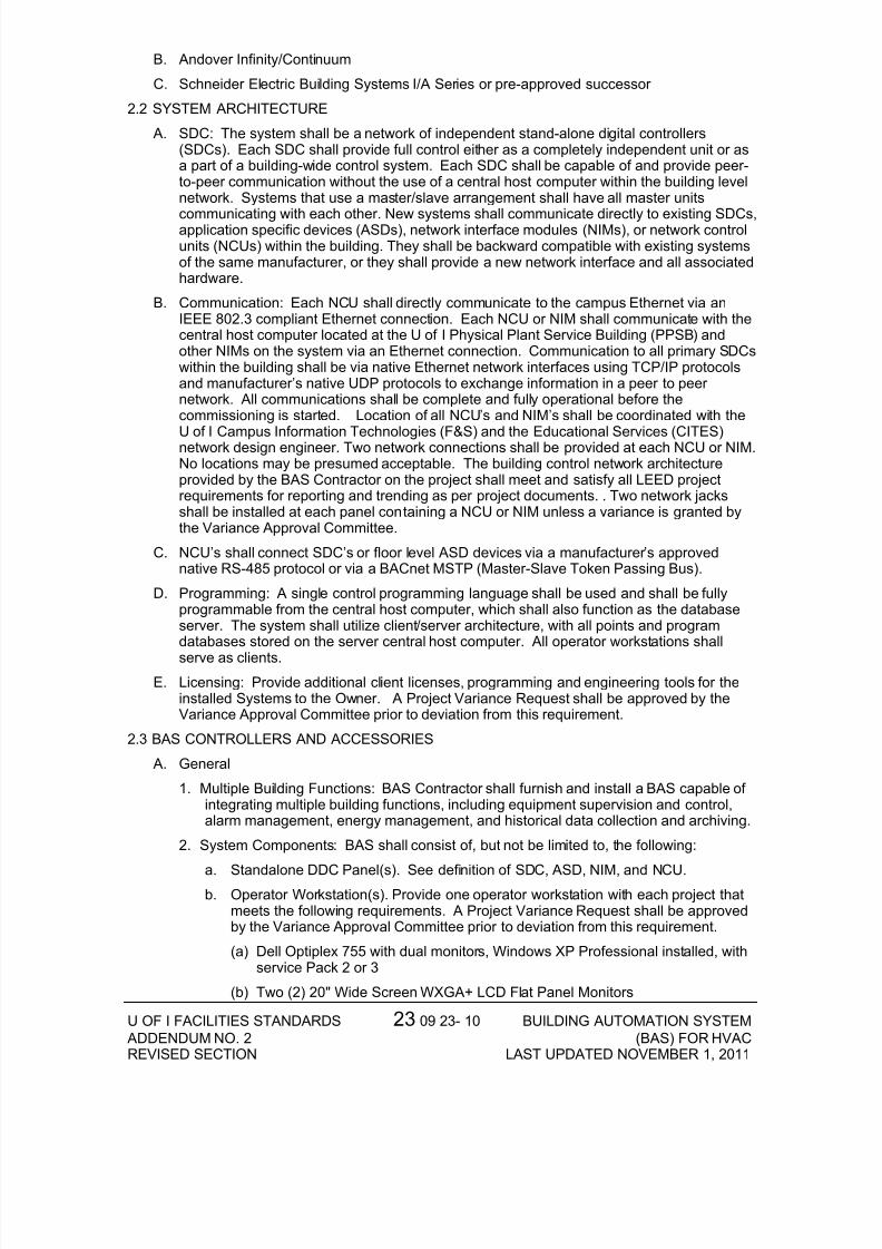
B. Andover Infinity/Continuum
C. Schneider Electric Building Systems I/A Series or pre-approved successor
2.2 SYSTEM ARCHITECTURE
A. SDC: The system shall be a network of independent stand-alone digital controllers(SDCs). Each SDC shall provide full control either as a completely independent unit or asa part of a building-wide control system. Each SDC shall be capable of and provide peer-to-peer communication without the use of a central host computer within the building levelnetwork. Systems that use a master/slave arrangement shall have all master units
communicating with each other. New systems shall communicate directly to existing SDCs,application specific devices (ASDs), network interface modules (NIMs), or network controlunits (NCUs) within the building. They shall be backward compatible with existing systemsof the same manufacturer, or they shall provide a new network interface and all associatedhardware.
B. Communication: Each NCU shall directly communicate to the campus Ethernet via anIEEE 802.3 compliant Ethernet connection. Each NCU or NIM shall communicate with thecentral host computer located at the U of I Physical Plant Service Building (PPSB) andother NIMs on the system via an Ethernet connection. Communication to all primary SDCswithin the building shall be via native Ethernet network interfaces using TCP/IP protocolsand manufacturer’s native UDP protocols to exchange information in a peer to peer network. All communications shall be complete and fully operational before thecommissioning is started. Location of all NCU’s and NIM’s shall be coordinated with the
U of I Campus Information Technologies (F&S) and the Educational Services (CITES)network design engineer. Two network connections shall be provided at each NCU or NIM.No locations may be presumed acceptable. The building control network architectureprovided by the BAS Contractor on the project shall meet and satisfy all LEED projectrequirements for reporting and trending as per project documents. . Two network jacksshall be installed at each panel containing a NCU or NIM unless a variance is granted bythe Variance Approval Committee.
C. NCU’s shall connect SDC’s or floor level ASD devices via a manufacturer’s approvednative RS-485 protocol or via a BACnet MSTP (Master-Slave Token Passing Bus).
D. Programming: A single control programming language shall be used and shall be fullyprogrammable from the central host computer, which shall also function as the databaseserver. The system shall utilize client/server architecture, with all points and programdatabases stored on the server central host computer. All operator workstations shallserve as clients.
E. Licensing: Provide additional client licenses, programming and engineering tools for theinstalled Systems to the Owner. A Project Variance Request shall be approved by theVariance Approval Committee prior to deviation from this requirement.
2.3 BAS CONTROLLERS AND ACCESSORIES
A. General
1. Multiple Building Functions: BAS Contractor shall furnish and install a BAS capable of integrating multiple building functions, including equipment supervision and control,alarm management, energy management, and historical data collection and archiving.
2. System Components: BAS shall consist of, but not be limited to, the following:
a. Standalone DDC Panel(s). See definition of SDC, ASD, NIM, and NCU.b. Operator Workstation(s). Provide one operator workstation with each project that
meets the following requirements. A Project Variance Request shall be approvedby the Variance Approval Committee prior to deviation from this requirement.
(a) Dell Optiplex 755 with dual monitors, Windows XP Professional installed, withservice Pack 2 or 3
(b) Two (2) 20" Wide Screen WXGA+ LCD Flat Panel Monitors
7/31/2019 Building Automation System (BAS) for HVAC
http://slidepdf.com/reader/full/building-automation-system-bas-for-hvac 11/20
U OF I FACILITIES STANDARDS 23 09 23- 11 BUILDING AUTOMATION SYSTEM ADDENDUM NO. 2 (BAS) FOR HVACREVISED SECTION LAST UPDATED NOVEMBER 1, 2011
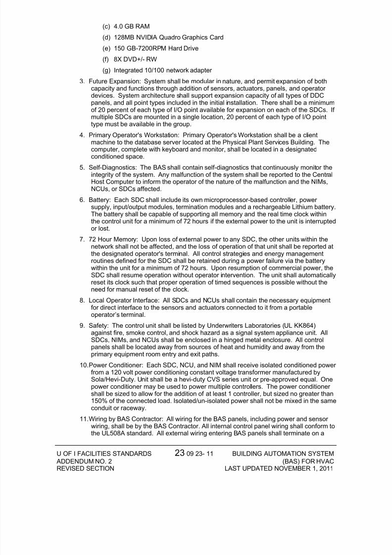
(c) 4.0 GB RAM
(d) 128MB NVIDIA Quadro Graphics Card
(e) 150 GB-7200RPM Hard Drive
(f) 8X DVD+/- RW
(g) Integrated 10/100 network adapter
3. Future Expansion: System shall be modular in nature, and permit expansion of bothcapacity and functions through addition of sensors, actuators, panels, and operator
devices. System architecture shall support expansion capacity of all types of DDCpanels, and all point types included in the initial installation. There shall be a minimumof 20 percent of each type of I/O point available for expansion on each of the SDCs. If multiple SDCs are mounted in a single location, 20 percent of each type of I/O pointtype must be available in the group.
4. Primary Operator's Workstation: Primary Operator's Workstation shall be a clientmachine to the database server located at the Physical Plant Services Building. Thecomputer, complete with keyboard and monitor, shall be located in a designatedconditioned space.
5. Self-Diagnostics: The BAS shall contain self-diagnostics that continuously monitor theintegrity of the system. Any malfunction of the system shall be reported to the CentralHost Computer to inform the operator of the nature of the malfunction and the NIMs,NCUs, or SDCs affected.
6. Battery: Each SDC shall include its own microprocessor-based controller, power supply, input/output modules, termination modules and a rechargeable Lithium battery.The battery shall be capable of supporting all memory and the real time clock withinthe control unit for a minimum of 72 hours if the external power to the unit is interruptedor lost.
7. 72 Hour Memory: Upon loss of external power to any SDC, the other units within thenetwork shall not be affected, and the loss of operation of that unit shall be reported atthe designated operator's terminal. All control strategies and energy managementroutines defined for the SDC shall be retained during a power failure via the batterywithin the unit for a minimum of 72 hours. Upon resumption of commercial power, theSDC shall resume operation without operator intervention. The unit shall automaticallyreset its clock such that proper operation of timed sequences is possible without the
need for manual reset of the clock.8. Local Operator Interface: All SDCs and NCUs shall contain the necessary equipment
for direct interface to the sensors and actuators connected to it from a portableoperator’s terminal.
9. Safety: The control unit shall be listed by Underwriters Laboratories (UL KK864)against fire, smoke control, and shock hazard as a signal system appliance unit. AllSDCs, NIMs, and NCUs shall be enclosed in a hinged metal enclosure. All controlpanels shall be located away from sources of heat and humidity and away from theprimary equipment room entry and exit paths.
10. Power Conditioner: Each SDC, NCU, and NIM shall receive isolated conditioned power from a 120 volt power conditioning constant voltage transformer manufactured bySola/Hevi-Duty. Unit shall be a hevi-duty CVS series unit or pre-approved equal. One
power conditioner may be used to power multiple controllers. The power conditioner shall be sized to allow for the addition of at least 1 controller, but sized no greater than150% of the connected load. Isolated/un-isolated power shall not be mixed in the sameconduit or raceway.
11. Wiring by BAS Contractor: All wiring for the BAS panels, including power and sensor wiring, shall be by the BAS Contractor. All internal control panel wiring shall conform tothe UL508A standard. All external wiring entering BAS panels shall terminate on a
7/31/2019 Building Automation System (BAS) for HVAC
http://slidepdf.com/reader/full/building-automation-system-bas-for-hvac 12/20
U OF I FACILITIES STANDARDS 23 09 23- 12 BUILDING AUTOMATION SYSTEM ADDENDUM NO. 2 (BAS) FOR HVACREVISED SECTION LAST UPDATED NOVEMBER 1, 2011
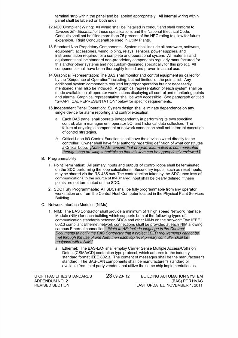
terminal strip within the panel and be labeled appropriately. All internal wiring withinpanel shall be labeled on both ends.
12. NEC Compliant Wiring: All wiring shall be installed in conduit and shall conform toDivision 26 - Electrical of these specifications and the National Electrical Code.Conduits shall not be filled more than 75 percent of the NEC rating to allow for futureexpansion. Rigid Conduit shall be used in Utility Plants.
13. Standard Non-Proprietary Components: System shall include all hardware, software,equipment, accessories, wiring, piping, relays, sensors, power supplies, andinstrumentation required for a complete and operational system. All materials andequipment shall be standard non-proprietary components regularly manufactured for this and/or other systems and not custom-designed specifically for this project. Allcomponents shall have been thoroughly tested and proven in actual use.
14. Graphical Representation: The BAS shall monitor and control equipment as called for by the "Sequence of Operation" including, but not limited to, the points list. Anyadditional system components required for proper operation but not necessarilymentioned shall also be included. A graphical representation of each system shall bemade available on all operator workstations displaying all control and monitoring pointsand alarms. Graphical representation shall be web accessible. See paragraph entitled“GRAPHICAL REPRESENTATION” below for specific requirements.
15. Independent Panel Operation: System design shall eliminate dependence on anysingle device for alarm reporting and control execution.
a. Each BAS panel shall operate independently in performing its own specifiedcontrol, alarm management, operator I/O, and historical data collection. Thefailure of any single component or network connection shall not interrupt executionof control strategies.
b. Critical Loop I/O Control Functions shall have the devices wired directly to thecontroller. Owner shall have final authority regarding definition of what constitutesa Critical Loop. [Note to AE: Ensure that program information is communicated through shop drawing submittals so that this item can be appropriately reviewed.]
B. Programmability
1. Point Termination: All primary inputs and outputs of control loops shall be terminatedon the SDC performing the loop calculations. Secondary inputs, such as reset inputs,may be shared via the RS-485 bus. The control action taken by the SDC upon loss of communications to the source of the shared input shall be clearly defined if thesepoints are not terminated on the SDC.
2. SDC Fully Programmable: All SDCs shall be fully programmable from any operator workstation and from the Central Host Computer located in the Physical Plant ServicesBuilding.
C. Network Interface Modules (NIMs)
1. NIM: The BAS Contractor shall provide a minimum of 1 high speed Network InterfaceModule (NIM) for each building which supports both of the following types of communication standards between SDCs and other NIMs on the network: Two IEEE802.3 compliant Ethernet network connections shall be provided at each NIM allowingcampus Ethernet connection . [Note to AE: Include language in the Contract Documents to notify the BAS Contractor that if project LEED requirements cannot be met through the use of one NIM, then each top level primary controller shall be equipped with a NIM.]
a. Ethernet: The BAS-LAN shall employ Carrier Sense Multiple Access/CollisionDetect (CSMA/CD) contention type protocol, which adheres to the industrystandard format IEEE 802.3. The content of messages shall be the manufacturer'sstandard. The BAS-LAN components shall be manufacturer's standard or available from third party vendors that utilize the same chip implementation as
7/31/2019 Building Automation System (BAS) for HVAC
http://slidepdf.com/reader/full/building-automation-system-bas-for-hvac 13/20
U OF I FACILITIES STANDARDS 23 09 23- 13 BUILDING AUTOMATION SYSTEM ADDENDUM NO. 2 (BAS) FOR HVACREVISED SECTION LAST UPDATED NOVEMBER 1, 2011
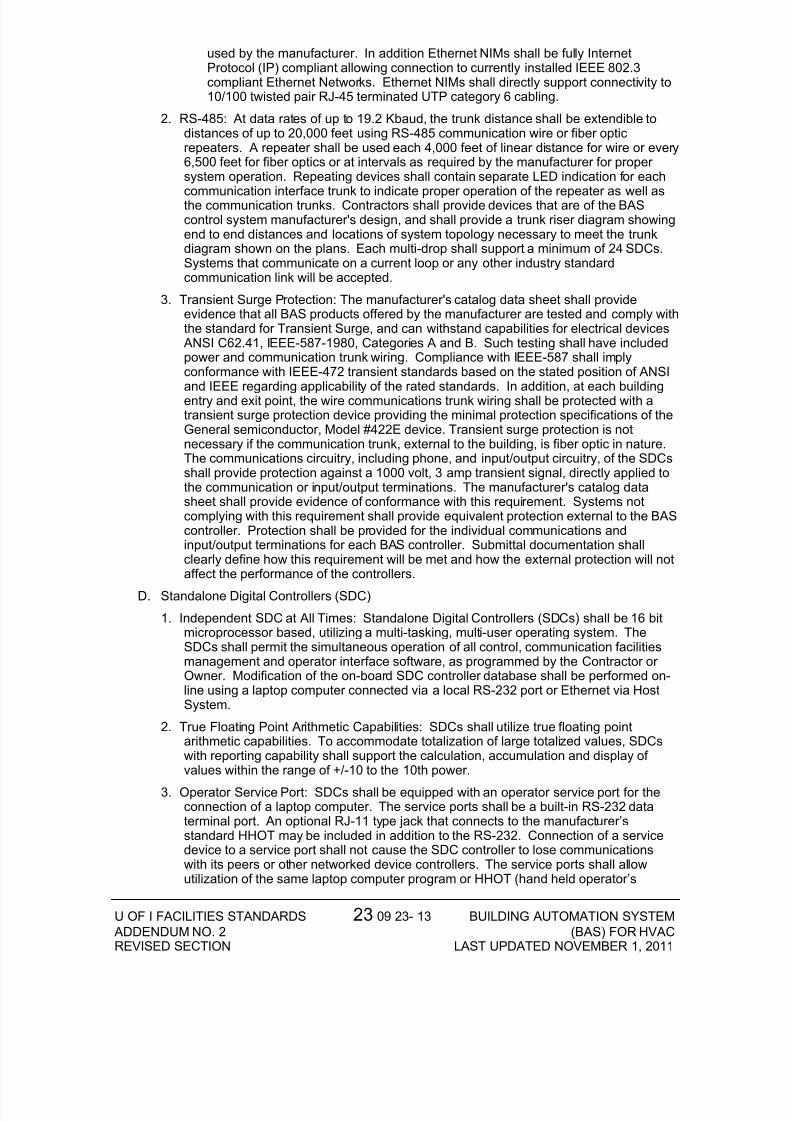
used by the manufacturer. In addition Ethernet NIMs shall be fully InternetProtocol (IP) compliant allowing connection to currently installed IEEE 802.3compliant Ethernet Networks. Ethernet NIMs shall directly support connectivity to10/100 twisted pair RJ-45 terminated UTP category 6 cabling.
2. RS-485: At data rates of up to 19.2 Kbaud, the trunk distance shall be extendible todistances of up to 20,000 feet using RS-485 communication wire or fiber opticrepeaters. A repeater shall be used each 4,000 feet of linear distance for wire or every6,500 feet for fiber optics or at intervals as required by the manufacturer for proper system operation. Repeating devices shall contain separate LED indication for each
communication interface trunk to indicate proper operation of the repeater as well asthe communication trunks. Contractors shall provide devices that are of the BAScontrol system manufacturer's design, and shall provide a trunk riser diagram showingend to end distances and locations of system topology necessary to meet the trunkdiagram shown on the plans. Each multi-drop shall support a minimum of 24 SDCs.Systems that communicate on a current loop or any other industry standardcommunication link will be accepted.
3. Transient Surge Protection: The manufacturer's catalog data sheet shall provideevidence that all BAS products offered by the manufacturer are tested and comply withthe standard for Transient Surge, and can withstand capabilities for electrical devices
ANSI C62.41, IEEE-587-1980, Categories A and B. Such testing shall have includedpower and communication trunk wiring. Compliance with IEEE-587 shall implyconformance with IEEE-472 transient standards based on the stated position of ANSI
and IEEE regarding applicability of the rated standards. In addition, at each buildingentry and exit point, the wire communications trunk wiring shall be protected with atransient surge protection device providing the minimal protection specifications of theGeneral semiconductor, Model #422E device. Transient surge protection is notnecessary if the communication trunk, external to the building, is fiber optic in nature.The communications circuitry, including phone, and input/output circuitry, of the SDCsshall provide protection against a 1000 volt, 3 amp transient signal, directly applied tothe communication or input/output terminations. The manufacturer's catalog datasheet shall provide evidence of conformance with this requirement. Systems notcomplying with this requirement shall provide equivalent protection external to the BAScontroller. Protection shall be provided for the individual communications andinput/output terminations for each BAS controller. Submittal documentation shallclearly define how this requirement will be met and how the external protection will notaffect the performance of the controllers.
D. Standalone Digital Controllers (SDC)
1. Independent SDC at All Times: Standalone Digital Controllers (SDCs) shall be 16 bitmicroprocessor based, utilizing a multi-tasking, multi-user operating system. TheSDCs shall permit the simultaneous operation of all control, communication facilitiesmanagement and operator interface software, as programmed by the Contractor or Owner. Modification of the on-board SDC controller database shall be performed on-line using a laptop computer connected via a local RS-232 port or Ethernet via HostSystem.
2. True Floating Point Arithmetic Capabilities: SDCs shall utilize true floating pointarithmetic capabilities. To accommodate totalization of large totalized values, SDCswith reporting capability shall support the calculation, accumulation and display of values within the range of +/-10 to the 10th power.
3. Operator Service Port: SDCs shall be equipped with an operator service port for theconnection of a laptop computer. The service ports shall be a built-in RS-232 dataterminal port. An optional RJ-11 type jack that connects to the manufacturer’sstandard HHOT may be included in addition to the RS-232. Connection of a servicedevice to a service port shall not cause the SDC controller to lose communicationswith its peers or other networked device controllers. The service ports shall allowutilization of the same laptop computer program or HHOT (hand held operator’s

7/31/2019 Building Automation System (BAS) for HVAC
http://slidepdf.com/reader/full/building-automation-system-bas-for-hvac 14/20
U OF I FACILITIES STANDARDS 23 09 23- 14 BUILDING AUTOMATION SYSTEM ADDENDUM NO. 2 (BAS) FOR HVACREVISED SECTION LAST UPDATED NOVEMBER 1, 2011
terminal) from any location. The same laptop computer program or HHOT shall beutilized for any SDC or NIM. Systems that utilize more than one variety of laptopcomputer program or HHOT are not acceptable.
4. Override Capability: The SDC shall provide commanded override capability from thelaptop computer or HHOT. Such overrides shall be annunciated to the Central HostComputer. Such overrides shall be valid as long as power is applied to the controller.SDC indication of such manual override actions shall be provided as feedback statusindication points shown on the Drawings, in conjunction with the application programswithin the SDC. H/O/A switches remotely located at the SDC controller shall be
behind a locked panel or capable of being disabled through the control program.5. Adjustments: Every SDC shall provide adjustments for the functions specified. In
general, adjustments shall be provided for all setpoints used by controllers within eachcontrol panel, or adjustments to other parameters as specified. Adjustments shall beintegral to each individual SDC. From a single SDC user interface, any other SDC onthe network shall be accessible and full adjustment capabilities shall be provided.
6. Metal Enclosures: All SDCs, or any device not classified as an ASD controller, shall beenclosed in metal enclosures with suitable brackets for either wall or floor mountingand shall be furnished and installed with each system. They shall be fabricated fromeither steel or extruded aluminum and shall be equipped with hinged door and lock.Panels shall not be secured to any item of equipment.
E. Network Control Unit (NCU)
1. A Network Control Unit (NCU) is a SDC incorporating a built-in NIM. The NCU shallincorporate all of the features of the SDCs and NIMs as outlined above.
F. Application Specific Devices (ASD)
1. Independent ASD Operation At All Times: Application Specific Devices (ASD) shallutilize a multi-tasking, multi-user operating system. The ASDs shall permit thesimultaneous operation of all control, communication facilities management andoperator interface software, as programmed by the Contractor or Owner. Modificationof the on-board ASD controller database shall be performed on-line using a laptopcomputer connected via a local port or from an Operator Workstation. Systems thatrequire the ASD to be removed from service while BAS control sequences aremodified are not acceptable.
2. Power Loss Protection: All programming defining the functions to be performed by the ASD, including but not limited to application programs and point database within each ASD, shall be protected from loss due to power failure. Systems providing non-volatilememory for these functions are preferred. Systems not providing non-volatile memoryshall provide a system rechargeable battery backup system sufficient to provideprotection. Systems not in compliance shall provide for uninterrupted power to each
ASD.
3. Operator Service Port: ASDs shall be equipped with an operator service port for theconnection of a laptop computer. The service ports shall be a built-in data terminalport. Connection of a service device, to a service port, shall not cause the ASDcontroller to lose communications with its peers or other networked device controllers.The service ports shall allow utilization of the same laptop computer program or HHOTfrom any location. The same laptop computer program or HHOT shall be utilized for any ASD or NIM.
4. Adjustments: Every ASD shall provide adjustments for the functions specified. Ingeneral, adjustments shall be provided for all setpoints used by controllers within eachcontrol panel, or adjustments to other parameters as specified. Adjustments shall beintegral to each individual ASD. From a single ASD user interface, any other ASD onthe network shall be accessible and full adjustment capabilities shall be provided.
G. Communications
7/31/2019 Building Automation System (BAS) for HVAC
http://slidepdf.com/reader/full/building-automation-system-bas-for-hvac 15/20
U OF I FACILITIES STANDARDS 23 09 23- 15 BUILDING AUTOMATION SYSTEM ADDENDUM NO. 2 (BAS) FOR HVACREVISED SECTION LAST UPDATED NOVEMBER 1, 2011
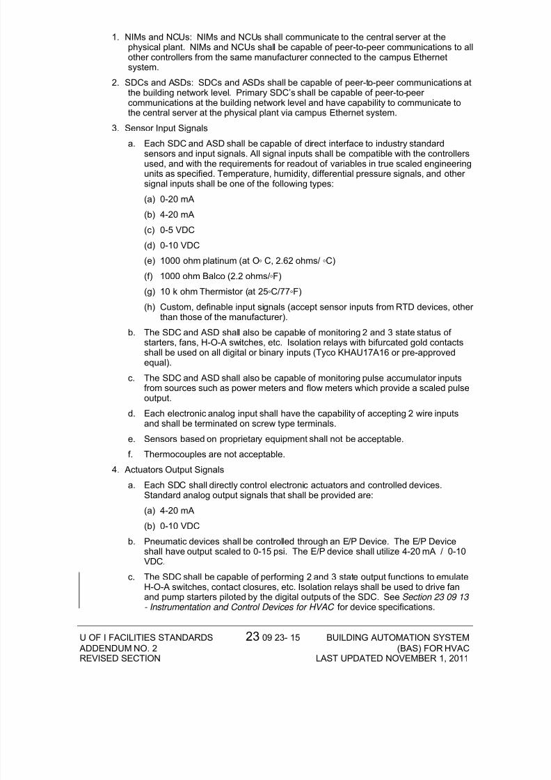
1. NIMs and NCUs: NIMs and NCUs shall communicate to the central server at thephysical plant. NIMs and NCUs shall be capable of peer-to-peer communications to allother controllers from the same manufacturer connected to the campus Ethernetsystem.
2. SDCs and ASDs: SDCs and ASDs shall be capable of peer-to-peer communications atthe building network level. Primary SDC’s shall be capable of peer-to-peer communications at the building network level and have capability to communicate tothe central server at the physical plant via campus Ethernet system.
3. Sensor Input Signals
a. Each SDC and ASD shall be capable of direct interface to industry standardsensors and input signals. All signal inputs shall be compatible with the controllersused, and with the requirements for readout of variables in true scaled engineeringunits as specified. Temperature, humidity, differential pressure signals, and other signal inputs shall be one of the following types:
(a) 0-20 mA
(b) 4-20 mA
(c) 0-5 VDC
(d) 0-10 VDC
(e) 1000 ohm platinum (at O ◦ C, 2.62 ohms/ ◦ C)
(f) 1000 ohm Balco (2.2 ohms/ ◦ F)
(g) 10 k ohm Thermistor (at 25 ◦ C/77 ◦ F)
(h) Custom, definable input signals (accept sensor inputs from RTD devices, other than those of the manufacturer).
b. The SDC and ASD shall also be capable of monitoring 2 and 3 state status of starters, fans, H-O-A switches, etc. Isolation relays with bifurcated gold contactsshall be used on all digital or binary inputs (Tyco KHAU17A16 or pre-approvedequal).
c. The SDC and ASD shall also be capable of monitoring pulse accumulator inputsfrom sources such as power meters and flow meters which provide a scaled pulseoutput.
d. Each electronic analog input shall have the capability of accepting 2 wire inputsand shall be terminated on screw type terminals.
e. Sensors based on proprietary equipment shall not be acceptable.
f. Thermocouples are not acceptable.
4. Actuators Output Signals
a. Each SDC shall directly control electronic actuators and controlled devices.Standard analog output signals that shall be provided are:
(a) 4-20 mA
(b) 0-10 VDC
b. Pneumatic devices shall be controlled through an E/P Device. The E/P Deviceshall have output scaled to 0-15 psi. The E/P device shall utilize 4-20 mA / 0-10VDC.
c. The SDC shall be capable of performing 2 and 3 state output functions to emulateH-O-A switches, contact closures, etc. Isolation relays shall be used to drive fanand pump starters piloted by the digital outputs of the SDC. See Section 23 09 13 - Instrumentation and Control Devices for HVAC for device specifications.
7/31/2019 Building Automation System (BAS) for HVAC
http://slidepdf.com/reader/full/building-automation-system-bas-for-hvac 16/20
U OF I FACILITIES STANDARDS 23 09 23- 16 BUILDING AUTOMATION SYSTEM ADDENDUM NO. 2 (BAS) FOR HVACREVISED SECTION LAST UPDATED NOVEMBER 1, 2011
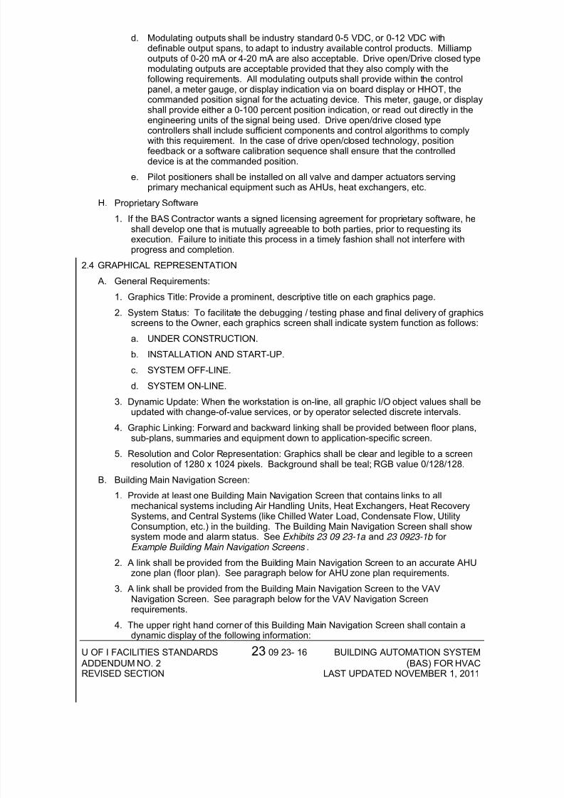
d. Modulating outputs shall be industry standard 0-5 VDC, or 0-12 VDC withdefinable output spans, to adapt to industry available control products. Milliampoutputs of 0-20 mA or 4-20 mA are also acceptable. Drive open/Drive closed typemodulating outputs are acceptable provided that they also comply with thefollowing requirements. All modulating outputs shall provide within the controlpanel, a meter gauge, or display indication via on board display or HHOT, thecommanded position signal for the actuating device. This meter, gauge, or displayshall provide either a 0-100 percent position indication, or read out directly in theengineering units of the signal being used. Drive open/drive closed typecontrollers shall include sufficient components and control algorithms to complywith this requirement. In the case of drive open/closed technology, positionfeedback or a software calibration sequence shall ensure that the controlleddevice is at the commanded position.
e. Pilot positioners shall be installed on all valve and damper actuators servingprimary mechanical equipment such as AHUs, heat exchangers, etc.
H. Proprietary Software
1. If the BAS Contractor wants a signed licensing agreement for proprietary software, heshall develop one that is mutually agreeable to both parties, prior to requesting itsexecution. Failure to initiate this process in a timely fashion shall not interfere withprogress and completion.
2.4 GRAPHICAL REPRESENTATION
A. General Requirements:1. Graphics Title: Provide a prominent, descriptive title on each graphics page.
2. System Status: To facilitate the debugging / testing phase and final delivery of graphicsscreens to the Owner, each graphics screen shall indicate system function as follows:
a. UNDER CONSTRUCTION.
b. INSTALLATION AND START-UP.
c. SYSTEM OFF-LINE.
d. SYSTEM ON-LINE.
3. Dynamic Update: When the workstation is on-line, all graphic I/O object values shall beupdated with change-of-value services, or by operator selected discrete intervals.
4. Graphic Linking: Forward and backward linking shall be provided between floor plans,sub-plans, summaries and equipment down to application-specific screen.
5. Resolution and Color Representation: Graphics shall be clear and legible to a screenresolution of 1280 x 1024 pixels. Background shall be teal; RGB value 0/128/128.
B. Building Main Navigation Screen:
1. Provide at least one Building Main Navigation Screen that contains links to allmechanical systems including Air Handling Units, Heat Exchangers, Heat RecoverySystems, and Central Systems (like Chilled Water Load, Condensate Flow, UtilityConsumption, etc.) in the building. The Building Main Navigation Screen shall showsystem mode and alarm status. See Exhibits 23 09 23-1a and 23 0923-1b for Example Building Main Navigation Screens .
2. A link shall be provided from the Building Main Navigation Screen to an accurate AHUzone plan (floor plan). See paragraph below for AHU zone plan requirements.
3. A link shall be provided from the Building Main Navigation Screen to the VAVNavigation Screen. See paragraph below for the VAV Navigation Screenrequirements.
4. The upper right hand corner of this Building Main Navigation Screen shall contain adynamic display of the following information:

7/31/2019 Building Automation System (BAS) for HVAC
http://slidepdf.com/reader/full/building-automation-system-bas-for-hvac 17/20
U OF I FACILITIES STANDARDS 23 09 23- 17 BUILDING AUTOMATION SYSTEM ADDENDUM NO. 2 (BAS) FOR HVACREVISED SECTION LAST UPDATED NOVEMBER 1, 2011
a. Global Outside Air Temperature.
b. Global Outdoor Air Humidity.
c. Global Outdoor Air Dew Point.
d. Global Outdoor Air Enthalpy.
5. The top middle of the page shall list the Building Name and Building Number. Also, alink shall be provided to the main “Illinois” BAS home page, which contains a list of active links to all the campus buildings.
C. AHU and Other Mechanical Equipment Graphics Screens (Heat Exchangers, EnthalpyWheels, Boilers, Chillers, etc.)
(Graphic details provided for AHU as an example).
1. Provide at least one Graphic display for each Air Handling Unit. Indicate in the top of the screen (above the graphics): Building Name, Building Number, Air Handling UnitName, Air Handling Unit Number, and Unit Location (mechanical room number). SeeExhibits 23 09 23-2a and 23 09 23-2b for Example AHU Graphics Screens .Graphically show the mechanical systems in as-built condition (i.e. do not use genericdrop-in graphics). Include a standard AHU graphics library with all of the controlsinstruments and mechanical devices and associated set points. Locate all instrumentsand control objects on the drawing (e.g. By-Pass Dampers, Control Dampers, ControlValves, Freeze-Stats, etc.) as they are installed in the field.
2. Control Set Points shall be clearly listed and exposed in a box above each instrument.3. Each control set point shall have override capability.
4. Show all Controls Inputs and Controls Outputs (AO, DO) on the screen.
5. The Owner shall be able to perform troubleshooting from this graphics screen.
6. The upper right hand corner of this screen shall contain information related to following: AHU scheduling, AHU start-up, and any mode change such as cooling lock out,economizer lock out, etc.
7. This graphics screen shall have a link to the most current version of the writtenSequence of Operations. The Sequence of Operations shall be updated at the end of the Project to reflect as-built conditions. A printable version of the Sequence of Operations shall be supplied as part of the graphics.
8. Provide color-coded floor (zone) plan with AHU service zones including hallways, etc.Multiple floor plans shall have a consistent color-code among floor plans. Distinctcolors shall be used to clearly differentiate between zones, and a legend shall beprovided if needed for clarity. If used, indicate and provide links to sub-plan areas.Emulate the project’s drawings for the zone plan backgrounds. Where applicable,include the mechanical room, HVAC equipment and control components locations,with corresponding links to the main mechanical pieces of equipment and AHU. Linksto these zone plans shall be provided from the Building Main Navigation Screen.These floor plans (zone drawings) shall reside in the control system database. SeeExhibit 23 09 23-3, Example AHU Zone Plan .
D. VAV / Terminal Units, Fan Coil Units and/or other HVAC Equipment Graphics Screens:
(Graphic details provided for VAV Boxes as an example.)
1. A VAV Main Navigation Screen shall be provided, containing links to all VAV SummaryTables and VAV Small Scale Zone Plans. A link to this VAV Main Navigation Screenshall be provided from the Building Navigation Screen. See Exhibits 23 09 23-04a and23 09 23-04b for Example VAV Navigation Screens .
2. VAV box and other HVAC equipment listing shall be provided in a form of a matrix or table on a summary table page. The table header shall include the following: Buildingnumber, AHU number servicing the associated VAV boxes, Room Number (location of
7/31/2019 Building Automation System (BAS) for HVAC
http://slidepdf.com/reader/full/building-automation-system-bas-for-hvac 18/20
U OF I FACILITIES STANDARDS 23 09 23- 18 BUILDING AUTOMATION SYSTEM ADDENDUM NO. 2 (BAS) FOR HVACREVISED SECTION LAST UPDATED NOVEMBER 1, 2011
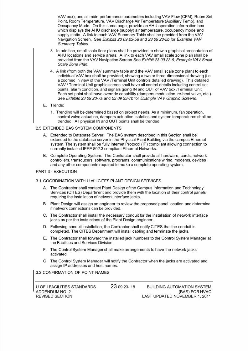
VAV box), and all main performance parameters including VAV Flow (CFM), Room SetPoint, Room Temperature, VAV Discharge Air Temperature (Auxiliary Temp), andOccupancy Mode. On this same page, provide an AHU operation information boxwhich displays the AHU discharge (supply) air temperature, occupancy mode andsupply static. A link to each VAV Summary Table shall be provided from the VAVNavigation Screen. See Exhibits 23 09 23-5a and 23 09 23-5b for Example VAV Summary Tables .
3. In addition, small scale floor plans shall be provided to show a graphical presentation of AHU locations and service areas. A link to each VAV small scale zone plan shall be
provided from the VAV Navigation Screen See Exhibit 23 09 23-6, Example VAV Small Scale Zone Plan .
4. A link (from both the VAV summary table and the VAV small scale zone plan) to eachindividual VAV box shall be provided, showing a two or three dimensional drawing (i.e.a zoomed in view of the VAV /Terminal Unit controls detailed drawing). This detailedVAV / Terminal Unit graphic screen shall have all control details including control setpoints, alarm condition, and signals going IN and OUT of VAV box /Terminal Unit.Each set point shall have override capability (dampers modulation, re-heat valve, etc.).See Exhibits 23 09 23-7a and 23 09 23-7b for Example VAV Graphic Screens .
E. Trends:
1. Trending will be determined based on project needs. As a minimum, fan operation,control valve actuation, dampers actuation, safeties and system temperatures shall be
trended. All physical IN and OUT points shall be trended.2.5 EXTENDED BAS SYSTEM COMPONENTS
A. Extended to Database Server: The BAS system described in this Section shall beextended to the database server in the Physical Plant Building via the campus Ethernetsystem. The system shall be fully Internet Protocol (IP) compliant allowing connection tocurrently installed IEEE 802.3 compliant Ethernet Networks.
B. Complete Operating System: The Contractor shall provide all hardware, cards, networkcontrollers, transducers, software, programs, communications wiring, modems, devicesand any other components required to make a complete operating system.
PART 3 - EXECUTION
3.1 COORDINATION WITH U of I CITES PLANT DESIGN SERVICES
A. The Contractor shall contact Plant Design of the Campus Information and TechnologyServices (CITES) Department and provide them with the location of their control panelsrequiring the installation of network interface jacks.
B. Plant Design will assign an engineer to review the proposed panel location and determineif network connections can be provided.
C. The Contractor shall install the necessary conduit for the installation of network interface jacks as per the instructions of the Plant Design engineer.
D. Following conduit installation, the Contractor shall notify CITES that the conduit iscompleted. The CITES Department will install cabling and terminate the jacks.
E. The Contractor shall forward the installed jack numbers to the Control System Manager atthe Facilities and Services Division.
F. The Control System Manager shall make arrangements to have the network jacksactivated.
G. The Control System Manager will notify the Contractor when the jacks are activated andassign IP addresses and host names.
3.2 CONFIRMATION OF POINT NAMES
7/31/2019 Building Automation System (BAS) for HVAC
http://slidepdf.com/reader/full/building-automation-system-bas-for-hvac 19/20
U OF I FACILITIES STANDARDS 23 09 23- 19 BUILDING AUTOMATION SYSTEM ADDENDUM NO. 2 (BAS) FOR HVACREVISED SECTION LAST UPDATED NOVEMBER 1, 2011
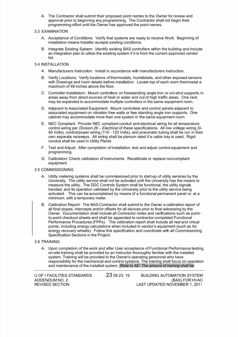
A. The Contractor shall submit their proposed point names to the Owner for review andapproval prior to beginning any programming. The Contractor shall not begin their programming effort until the Owner has approved the point names.
3.3 EXAMINATION
A. Acceptance of Conditions: Verify that systems are ready to receive Work. Beginning of installation means Installer accepts existing conditions.
B. Integrate Existing System: Identify existing BAS controllers within the building and includean integration plan to utilize the existing system if it is from the current approved vendor
list.3.4 INSTALLATION
A. Manufacturers Instruction: Install in accordance with manufacturers instruction.
B. Verify Locations: Verify locations of thermostats, humidistats, and other exposed sensorswith Drawings and room details before installation. Locate top of each room thermostat amaximum of 48 inches above the floor.
C. Controller Installation: Mount controllers on freestanding angle iron or uni-strut supports inareas away from direct sources of heat or water and out of high traffic areas. One rackmay be expanded to accommodate multiple controllers in the same equipment room.
D. Adjacent to Associated Equipment: Mount controllers and control panels adjacent toassociated equipment on vibration free walls or free standing angle iron supports. One
cabinet may accommodate more than one system in the same equipment room.E. NEC Compliant: Provide NEC compliant conduit and electrical wiring for all temperature
control wiring per Division 26 – Electrical of these specifications. All low voltage wiring (0-40 Volts), control/power wiring (110 - 120 Volts), and pneumatic tubing shall be run in their own separate raceways. All wiring shall be plenum rated if a cable tray is used. Rigidconduit shall be used in Utility Plants.
F. Test and Adjust: After completion of installation, test and adjust control equipment andprogramming.
G. Calibration: Check calibration of instruments. Recalibrate or replace noncompliantequipment.
3.5 COMMISSIONING
A. Utility metering systems shall be commissioned prior to start-up of utility services by theUniversity. The utility service shall not be activated until the University has the means tomeasure the utility. The DDC Controls System shall be functional, the utility signalstrended, and its operation validated by the University prior to the utility service beingactivated. This can be accomplished by means of a functional permanent panel or, at aminimum, with a temporary meter.
B. Calibration Report: The BAS Contractor shall submit to the Owner a calibration report of all final slopes, intercepts and/or offsets for all devices prior to final witnessing by theOwner. Documentation shall include all Contractor notes and verifications such as point-to-point checkout sheets and shall be appended to contractor-completed FunctionalPerformance Procedures (FPPs). The calibration report shall include all real and virtualpoints, including energy calculations when included in vendor’s equipment (such as for energy recovery wheels). Follow this specification and coordinate with all Commissioning
Specification Sections in the Project.3.6 TRAINING
A. Upon completion of the work and after User acceptance of Functional Performance testing,on-site training shall be provided by an instructor thoroughly familiar with the installedsystem. Training will be provided to the Owner's operating personnel who haveresponsibility for the mechanical and control systems. The training shall focus on operationand maintenance of the installed system. [Note to AE: The amount of training shall be
7/31/2019 Building Automation System (BAS) for HVAC
http://slidepdf.com/reader/full/building-automation-system-bas-for-hvac 20/20
U OF I FACILITIES STANDARDS 23 09 23- 20 BUILDING AUTOMATION SYSTEM ADDENDUM NO. 2 (BAS) FOR HVACREVISED SECTION LAST UPDATED NOVEMBER 1, 2011
provided and shall match the size of the project (e.g., no less than eight hours for small projects and up to 40 hours for large projects). Specify exact hours in the Contract Documents].
B. [Note to AE: Personnel factory training shall be provided for User if an approved manufacturer is new to the University or if User deems necessary during project design phase. This training shall be scheduled after substantial completion. The project shall include training for 4 workers for one week typically, at a level necessary to successfully operate the BAS supplied. The Contractor will not bear the cost of transportation, meals and lodging of the University’s personnel.]
END OF SECTION 23 09 23
This section of the U of I Facilities Standards establishes minimum requirements only.It should not be used as a complete specification.