Building an environment for validating BMS functionality ...
4
BATTERY CELL VOLTAGE GENERATOR SS7081-50 Building an environment for validating BMS * 1 functionality has never been easier Introducing a 12-channel battery cell voltage generator that delivers power supply, electronic load, and DMM functionality in a single package. The SS7081-50’s simple architecture makes building an environment for validating BMS functionality more affordable and productive than ever before. * 2 Calibration is performed according to customer-specified calibration points within the scope of certification. Calibration is not available for the entire specification range of the product. * 1 BMS: Battery Management System ISO/IEC 17025* 2
Transcript of Building an environment for validating BMS functionality ...

BATTERY CELL VOLTAGE GENERATOR SS7081-50
Building an environment for validating BMS*1 functionality has never been easier
Introducing a 12-channel battery cell voltage generator that delivers power supply, electronic load, and DMM functionality in a single package. The SS7081-50’s simple architecture makes building an environment for validating BMS functionality more affordable and productive than ever before.
*2 Calibration is performed according to customer-specified calibration points within the scope of certification. Calibration is not available for the entire specification range of the product.
*1 BMS: Battery Management System
ISO/IEC 17025*2
2
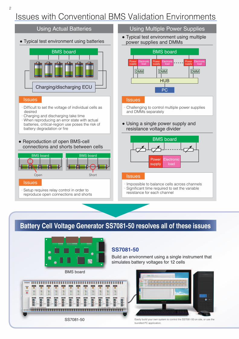
Issues with Conventional BMS Validation Environments
Battery Cell Voltage Generator SS7081-50 resolves all of these issues
· Difficult to set the voltage of individual cells as desired
· Charging and discharging take time· When reproducing an error state with actual
batteries, critical-region use poses the risk of battery degradation or fire
Issues· Challenging to control multiple power supplies
and DMMs separately
· Impossible to balance cells across channels· Significant time required to set the variable
resistance for each channel· Setup requires relay control in order to reproduce open connections and shorts
Issues
IssuesIssues
Using Actual Batteries Using Multiple Power Supplies
Build an environment using a single instrument that simulates battery voltages for 12 cells
SS7081-50
BMS board
SS7081-50 Easily build your own system to control the SS7081-50 on site, or use the bundled PC application.
● Typical test environment using multiple power supplies and DMMs
● Reproduction of open BMS-cell connections and shorts between cells
● Typical test environment using batteries
● Using a single power supply and resistance voltage divider
BMS board
BMS board
Power supply
Electronic load
BMS board
HUB
PC
Electronic load
Electronic load
Electronic load
Power supply
Power supply
Power supply
BMS board BMS board
ShortOpen
DMM DMM DMM
Charging/discharging ECU

3
● Safer than using actual batteries and separate power supplies
● High-accuracy, high-precision output and testing
Build a highly accurate BMS validation environment easily and safely
• Simulate cell behavior in individual channels, with 12 channels per SS7081-50 unit
• Build a large-scale module environment with a series voltage of 1000 V (5 V/channel × 200 channels = 1000 V)
• Simulate cell anomalies that would pose the risk of fire if using actual batteries
• Simulate open-wire malfunctions between channels and the BMS
• Simulate cell shorts
• Simulate cell behavior using high-accuracy voltage output• Take advantage of cell balancing from -1 A to 1 A
with two-quadrant output voltages
• High-accuracy, high-precision voltage and current measurement• Measure minuscule currents using the 100 μA range
(for BMS dark current and cell balancing circuit leakage current)
Output range per channel
Continuous output
Continuous output
Output time200 ms
Output time200 ms
5
-1 1-0.21
Voltage [V]
Current [A]0.210
12
No. of channels
Generated voltage
5 V/channel1000 V
Max. series generated voltage
±0.015%Voltage output
accuracy
Voltage measurement
accuracy
±0.01%
Current measurement
accuracy1 A range: ±0.07%100 μA range: ±0.035%
Simplify evaluation with the bundled PC application• Control up to ten SS7081-50 units• Automate testing by creating sequences of the simulated states you wish to reproduce
Open and short simulation with the SS7081-50
SS7081-50
V V V
A A A
BMS board

HEADQUARTERS 81 Koizumi, Ueda, Nagano 386-1192 Japan
https://www.hioki.com/
All information correct as of Apr. 15, 2020. All specifications are subject to change without notice. SS7081-50E1-04M Printed in Japan
DISTRIBUTED BY
Note: Company names and product names appearing in this catalog are trademarks or registered trademarks of various companies.
Please contact your HIOKI distributor for a demonstration unit and further specifications.
Specifications
Example system architecture
Model
System based on a HIOKI Memory HiCorder and Non-Contact CAN Sensor
MEMORY HiCORDER MR6000
NON-CONTACT CAN SENSOR SP7001-90
• Data and waveform logging• Temperature measurement
• Capture CAN signals (MR6000 Ver. 3.0*)
* Using the VN1600 family of interfaces from Vector
+
(Accuracy guaranteed for 1 year, accuracy after adjustment guaranteed for 1 year)
SP7001-90
MR6000
SS7081-50
Number of channels 12
Maximum in-seriesconnections
In-series connections of instrument up to and including amaximum in-series output voltage of 1000 V
Output range
DC voltage 0.0000 V to 5.0250 V (set independently for all channels)
Maximum outputcurrent
±1.00000 A (set independently for all channels)Continuous output: -210 mA to 210 mAContinuous output of currents greater than 210 mA or less than -210 mA is subject to limitations*.*Continuous output limitationsMax. output time: 200 msTime to next output (reference value): If outputting 1 A at 5 V for 200 ms, 5 s
Measurement range
DC voltage -0.00100 V to 5.10000 V
DC current(2-range architecture)
±1.20000 A (1 A range)±120.0000 μA (100 μA range)
Integration time 1 PLC (50 Hz: 20 ms; 60 Hz: 16.7 ms) × number of smoothing iterations (user-configured)
Voltage output accuracy
±0.0150% of setting ±500 μVAdditional error (temperature coefficient)0℃ to 18℃, 28℃ to 40℃: Add the following value per 1℃:±0.05 × output accuracy/℃Output resistance: 3 mΩ or less (not including terminal contact resistance)
Voltage measure-ment accuracy
±0.0100% of reading ±100 μVAdditional error (temperature coefficient)0℃ to 18℃, 28℃ to 40℃: Add the following value per 1℃:±0.05% × measurement accuracy/℃
Current measure-ment accuracy
1 A range
±0.0700% of reading ±100 μAAdditional error (temperature coefficient)0℃ to 18℃, 28℃ to 40℃: Add the following value per 1℃:±0.05% × measurement accuracy/℃
100 μA range
±0.0350% of reading ±10 nAAdditional error (temperature coefficient)0℃ to 18℃, 28℃ to 40℃: Add the following value per 1℃:±0.05% × measurement accuracy/℃
Accuracy guarantee temperature and humidity range
23℃ ±5℃, 80% RH (with warm-up time of at least 30 min.)
Power supply Universal (100 V to 240 V AC)
Power supply frequency range 50 Hz / 60 Hz, ±2 Hz
Interfaces
LAN Supported standard: IEEE 802.3Transmission method: 10Base-T/100Base-TX, automatic detection, full duplexProtocol: TCP/IPConnector: RJ-45Functionality: Configuration of settings and acquisition of device status and measured values using communications commandsSettings: IP address: 192.168.1.xxx (only the xxx portion is user-configured)Subnet mask: 255.255.255.0 (fixed)Default gateway: None (fixed)Communications command port: 1024 (fixed)Default setting: IP address: 192.168.1.1
Dimensions and mass
430 (16.93 in)W ±3 mm (0.12 in) × 132 (5.20 in)H ±3 mm (0.12 in) ×483 (19.02 in)D ±3 mm (0.12 in), 10.3 kg (363.3 oz.) ±0.5 kg (17.6 oz.)
Accessories User manual, power cord, rack frame, disk with computer application
Model: BATTERY CELL VOLTAGE GENERATOR SS7081-50
Model No. (Order Code) : SS7081-50