BUILDING AN AUTONOMOUS HUMANOID TOOL...
20
BUILDING AN AUTONOMOUS HUMANOID TOOL USER WILLIAM BLUETHMANN NASA Johnson Space Center, 2101 NASA Parkway, M/C ER3 Houston, TX 77058 USA [email protected] ROBERT AMBROSE, MYRON DIFTLER, ERIC HUBER Dexterous Robotic Laboratory, NASA JSC, 2101 NASA Parkway Houston, TX 77058 USA ambrose,[email protected], [email protected] ANDY FAGG, MICHAEL ROSENSTEIN, ROBERT PLATT, RODERIC GRUPEN Computer Science Department, University of Massachusetts Amherst, MA 01003 USA G rupen grupen, fagg,mtr,[email protected] CYNTHIA BREAZEAL, ANDREW BROOKS, ANDREA LOCKERD MIT Media Lab, Massachusetts Institute of Technology Cambridge, MA 02139 USA cynthiab,zoz,[email protected] R. ALAN PETERS Electrical Engineering & Computer Science, Vanderbilt University, Nashville, TN 37235 USA [email protected] O. CHAD JENKINS, MAJA MATARIC Computer Science Department, Unversity of Southern California Los Angeles, CA 90089 USA cjenkins, [email protected] MAGDALENA. BUGAJSKA Navy Center for Applied Research in Artificial Intelligence, Naval Research Laboratory (NRL) Washington, DC 20375 [email protected] Abstract To make the transition from a technological curiosity to productive tools, humanoid robots will require key advances in many areas, including, mechanical design, sensing, embedded avionics, power, and navigation. Using the NASA Johnson Space Center’s Robonaut as a testbed, the DARPA Mobile Autonomous Robot Software (MARS) Humanoids team is investigating technologies that will enable humanoid robots to work effectively with humans and autonomously work with tools. A novel learning approach is being applied that enables the robot to learn both from a remote human teleoperating the robot and an adjacent human giving instruction. When the remote human performs tasks teleoperatively, the robot learns the salient sensory-motor features for executing the task. Once learned, the task may be carried out by fusing the skills required to perform the task, guided by on-board sensing. The adjacent human takes advantage of previously learned skills to sequence the execution of these skills. Preliminary results from initial experiments using a drill to tighten lug nuts on a wheel are discussed. Keywords: Humanoid robots, Robonaut, dexterity, robotic tool use.
-
Upload
phamnguyet -
Category
Documents
-
view
215 -
download
1
Transcript of BUILDING AN AUTONOMOUS HUMANOID TOOL...
BUILDING AN AUTONOMOUS HUMANOID TOOL USER
WILLIAM BLUETHMANN NASA Johnson Space Center, 2101 NASA Parkway, M/C ER3
Houston, TX 77058 USA [email protected]
ROBERT AMBROSE, MYRON DIFTLER, ERIC HUBER
Dexterous Robotic Laboratory, NASA JSC, 2101 NASA Parkway Houston, TX 77058 USA
ambrose,[email protected], [email protected]
ANDY FAGG, MICHAEL ROSENSTEIN, ROBERT PLATT, RODERIC GRUPEN Computer Science Department, University of Massachusetts
Amherst, MA 01003 USA Grupengrupen, fagg,mtr,[email protected]
CYNTHIA BREAZEAL, ANDREW BROOKS, ANDREA LOCKERD
MIT Media Lab, Massachusetts Institute of Technology Cambridge, MA 02139 USA
cynthiab,zoz,[email protected]
R. ALAN PETERS Electrical Engineering & Computer Science, Vanderbilt University,
Nashville, TN 37235 USA [email protected]
O. CHAD JENKINS, MAJA MATARIC
Computer Science Department, Unversity of Southern California Los Angeles, CA 90089 USA cjenkins, [email protected]
MAGDALENA. BUGAJSKA
Navy Center for Applied Research in Artificial Intelligence, Naval Research Laboratory (NRL) Washington, DC 20375 [email protected]
Abstract
To make the transition from a technological curiosity to productive tools, humanoid robots will require key advances in many areas, including, mechanical design, sensing, embedded avionics, power, and navigation. Using the NASA Johnson Space Center’s Robonaut as a testbed, the DARPA Mobile Autonomous Robot Software (MARS) Humanoids team is investigating technologies that will enable humanoid robots to work effectively with humans and autonomously work with tools. A novel learning approach is being applied that enables the robot to learn both from a remote human teleoperating the robot and an adjacent human giving instruction. When the remote human performs tasks teleoperatively, the robot learns the salient sensory-motor features for executing the task. Once learned, the task may be carried out by fusing the skills required to perform the task, guided by on-board sensing. The adjacent human takes advantage of previously learned skills to sequence the execution of these skills. Preliminary results from initial experiments using a drill to tighten lug nuts on a wheel are discussed.
Keywords: Humanoid robots, Robonaut, dexterity, robotic tool use.
Administrator
Proc. IEEE-RAS Internl. Conf on Humanoid Robotics, Los Angeles, CA, Nov 2004
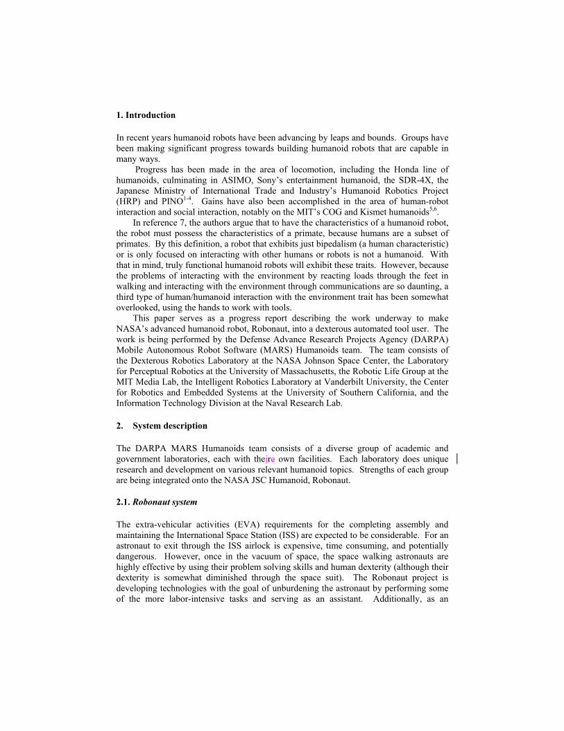
1. Introduction
In recent years humanoid robots have been advancing by leaps and bounds. Groups have been making significant progress towards building humanoid robots that are capable in many ways.
Progress has been made in the area of locomotion, including the Honda line of humanoids, culminating in ASIMO, Sony’s entertainment humanoid, the SDR-4X, the Japanese Ministry of International Trade and Industry’s Humanoid Robotics Project (HRP) and PINO1-4. Gains have also been accomplished in the area of human-robot interaction and social interaction, notably on the MIT’s COG and Kismet humanoids5,6.
In reference 7, the authors argue that to have the characteristics of a humanoid robot, the robot must possess the characteristics of a primate, because humans are a subset of primates. By this definition, a robot that exhibits just bipedalism (a human characteristic) or is only focused on interacting with other humans or robots is not a humanoid. With that in mind, truly functional humanoid robots will exhibit these traits. However, because the problems of interacting with the environment by reacting loads through the feet in walking and interacting with the environment through communications are so daunting, a third type of human/humanoid interaction with the environment trait has been somewhat overlooked, using the hands to work with tools.
This paper serves as a progress report describing the work underway to make NASA’s advanced humanoid robot, Robonaut, into a dexterous automated tool user. The work is being performed by the Defense Advance Research Projects Agency (DARPA) Mobile Autonomous Robot Software (MARS) Humanoids team. The team consists of the Dexterous Robotics Laboratory at the NASA Johnson Space Center, the Laboratory for Perceptual Robotics at the University of Massachusetts, the Robotic Life Group at the MIT Media Lab, the Intelligent Robotics Laboratory at Vanderbilt University, the Center for Robotics and Embedded Systems at the University of Southern California, and the Information Technology Division at the Naval Research Lab.
2. System description
The DARPA MARS Humanoids team consists of a diverse group of academic and government laboratories, each with theire own facilities. Each laboratory does unique research and development on various relevant humanoid topics. Strengths of each group are being integrated onto the NASA JSC Humanoid, Robonaut.
2.1. Robonaut system
The extra-vehicular activities (EVA) requirements for the completing assembly and maintaining the International Space Station (ISS) are expected to be considerable. For an astronaut to exit through the ISS airlock is expensive, time consuming, and potentially dangerous. However, once in the vacuum of space, the space walking astronauts are highly effective by using their problem solving skills and human dexterity (although their dexterity is somewhat diminished through the space suit). The Robonaut project is developing technologies with the goal of unburdening the astronaut by performing some of the more labor-intensive tasks and serving as an assistant. Additionally, as an

extravehicular robot, Robonaut will have the ability to perform emergency work at a moment’s notice. Robonaut is NASA’s most ambitious humanoid system, Figure 1.
Fig. 1. Robonaut Units A and B
In opposition to other space robots, Robonaut is designed to work in an environment designed for use by humans8,9. The requirements for interacting with space station EVA crew interfaces and tools provided the starting point for the Robonaut design10. To a large extent these requirements drive the subsystem designs, for example, a maximum force of 20 lbs and torque of 30 in-lbs is required to remove and install Orbital Replacement Units (ORU).
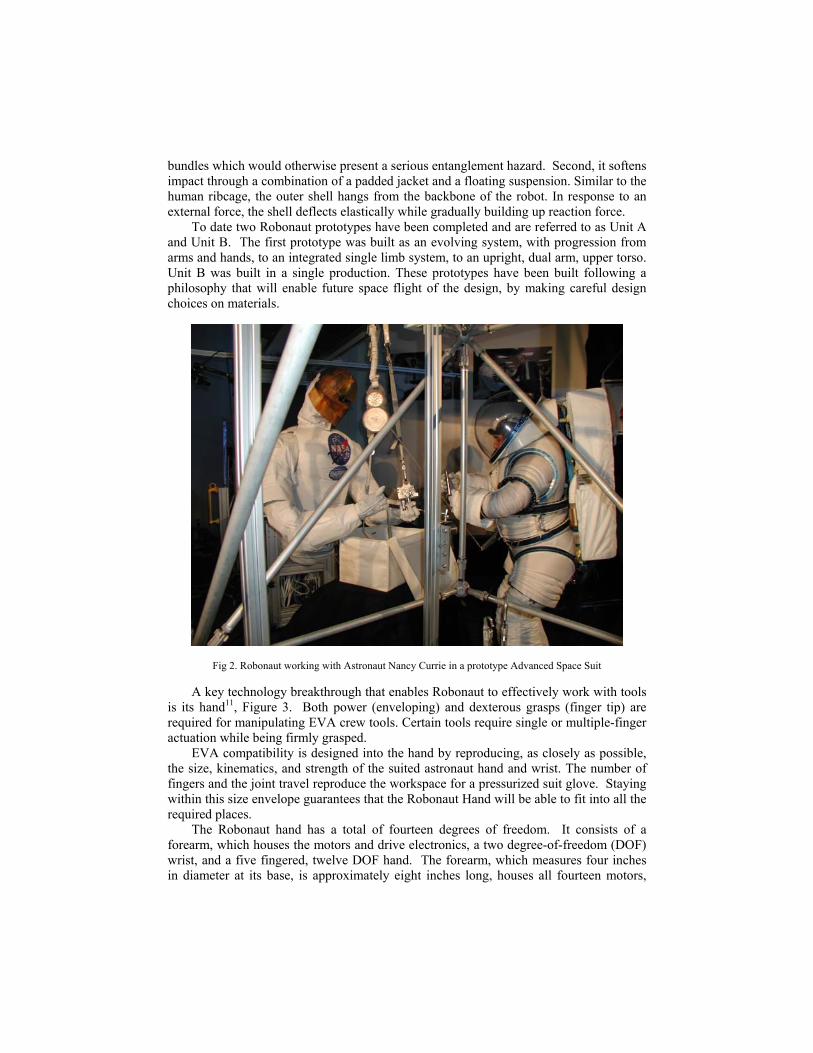
The EVA requirements also drive the Robonaut design in more subtle ways. The human-rated space environment has been engineered for the astronaut to be able to work in a safe, reliable, and efficient manner. The dimensions of Robonaut are guided by the size of the astronaut in the Extravehicular Mobility Unit (EMU), Figure 2. The Space Station requires that areas designed to be accessible by humans have corridors that the EVA astronaut can fit into. Because Robonaut is similar in size to the EMU, it also can fit through the access corridors.
Another requirement for EVA hardware is that the tools don’t have sharp edges that may nick or cut the astronaut’s suit. From one perspective, Robonaut is an EVA tool; it is therefore covered in a skin that prevents the astronaut from contacting any sharp edges. From another perspective, Robonaut is a user of EVA tools. The skin also prevents the robot from creating sharp edges or burrs on tools or handholds an astronaut may later contact.
A carbon fiber outer shell further protects the robot from damage. The outer shell safeguards the robot in two ways. First, it hides fragile electronic components and wire
bundles which would otherwise present a serious entanglement hazard. Second, it softens impact through a combination of a padded jacket and a floating suspension. Similar to the human ribcage, the outer shell hangs from the backbone of the robot. In response to an external force, the shell deflects elastically while gradually building up reaction force.
To date two Robonaut prototypes have been completed and are referred to as Unit A and Unit B. The first prototype was built as an evolving system, with progression from arms and hands, to an integrated single limb system, to an upright, dual arm, upper torso. Unit B was built in a single production. These prototypes have been built following a philosophy that will enable future space flight of the design, by making careful design choices on materials.
Fig 2. Robonaut working with Astronaut Nancy Currie in a prototype Advanced Space Suit
A key technology breakthrough that enables Robonaut to effectively work with tools is its hand11, Figure 3. Both power (enveloping) and dexterous grasps (finger tip) are required for manipulating EVA crew tools. Certain tools require single or multiple-finger actuation while being firmly grasped.
EVA compatibility is designed into the hand by reproducing, as closely as possible, the size, kinematics, and strength of the suited astronaut hand and wrist. The number of fingers and the joint travel reproduce the workspace for a pressurized suit glove. Staying within this size envelope guarantees that the Robonaut Hand will be able to fit into all the required places.
The Robonaut hand has a total of fourteen degrees of freedom. It consists of a forearm, which houses the motors and drive electronics, a two degree-of-freedom (DOF) wrist, and a five fingered, twelve DOF hand. The forearm, which measures four inches in diameter at its base, is approximately eight inches long, houses all fourteen motors,

twelve separate circuit boards, and all of the wiring for the hand. Overall the hand is equipped with forty-three sensors. Each joint is equipped with embedded absolute position sensors and each motor is equipped with incremental encoders.
Robonaut has three serial chains emerging from the body: two upper arms for dexterous work, and a neck for pointing the head, Figure 3. These chains are all built with a common technology, best described as a family of modular joints, characterized by size and kinematic motion type. There are four torque ranges, from 10 ft-lbs to 200 ft-lbs, and two motion types, roll and pitch. When coupled with the wrist, the arms are seven DOF devices. The neck is a two DOF device on Unit A and a three DOF device on Unit B, Figure 3.
Fig. 3. The Robonaut hand, arm, and head
The lower body of Robonaut yields a wide variety of options for either providing further dexterity or mobility, Figure 4. The most basic lower body is the 0g option, where a dexterous leg, consisting of another chain of the family of modular joints used in the arms and neck, is mounted below the upper body. During operations, the leg is inserted into a worksite interface (WIF) socket to provide upper body re-positioning and load path to structure. Additionally, the leg may be used to transport payloads or provide momentum management during climbing procedures12.
For terrestrial applications, the Robonaut upper torso has been placed upon a two-wheeled base, a modified version of the SegwayTM Human Transportera. The primary development objective for the wheeled Robonaut system was to identify control options for mobile, dexterous, dual arm robots13. A secondary objective was to investigate this wheeled configuration of Robonaut for terrestrial service roles such as bomb disposal, plant maintenance, and security. In the future, a lower body capable of operation on more uneven terrain is envisioned. This concept, often referred to as centaur, places the dexterous upper body onto a four-wheeled rover lower body.
Robonaut Unit A uses a three-jointed version of the leg, giving it waist mobility. Waist mobility complements the dexterity of a dual arm system, allowing the intersection of the two arm’s dexterous workspaces to be repositioned around a work site, enabling the use of smaller, closely configured arms to perform dexterous manipulation over a large resultant workspace.
a Commercial products identified are for informational purposes only. This neither serves as an endorsement nor implies the product is necessarily the best suited to the application.
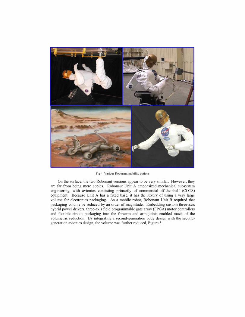
Fig 4. Various Robonaut mobility options
On the surface, the two Robonaut versions appear to be very similar. However, they are far from being mere copies. Robonaut Unit A emphasized mechanical subsystem engineering, with avionics consisting primarily of commercial-off-the-shelf (COTS) equipment. Because Unit A has a fixed base, it has the luxury of using a very large volume for electronics packaging. As a mobile robot, Robonaut Unit B required that packaging volume be reduced by an order of magnitude. Embedding custom three-axis hybrid power drivers, three-axis field programmable gate array (FPGA) motor controllers and flexible circuit packaging into the forearm and arm joints enabled much of the volumetric reduction. By integrating a second-generation body design with the second-generation avionics design, the volume was further reduced, Figure 5.

Fig 5. Robonaut Unit B body packaging
2.2. Software architecture
The Robonaut software system is being developed with the ability to work with and in the presences of humans. The control system design is inspired by the human brain anatomy. The human brain embeds some functions, such as gaits, reactive reflexes and sensing, at a very low level, in the spinal cord or nerves14. Higher brain functions, such as cognition and planning take place in other parts of the brain, including the cerebral cortex, thalamus, and cerebellum.
Within the Robonaut control system, the very low level functions are referred to as the brainstem. The brainstem contains the motion controllers for the 40+ DOF, sensing, safety functions, and low level sequencing. As a humanoid robot designed for the purpose of working in the proximity of humans, safety is the key component of Robonaut’s control design. By embedding safety systems at a low level, safety and overall performance are improved.
Using the brainstem approach allows higher-level functions to operate independently of the low level functions. This allows the implementation of a variety of control methods with the brainstem unaware of which higher-level control system is being used. This also enables the pieces of the software system that reside nearest to the hardware to be the final arbiters of what qualifies as safe operation.
An Application Programmer’s Interface (API) exists as a method of communicating from external sources to the Robonaut brainstem. This standard interface allows systems to both monitor and modify the state of the Robonaut brainstem. Additionally, Robonaut’s API creates an environment where software integration between systems developed by the various members of the team is relatively seamless. To define a new communications channel between two or more processes, the producers and consumers of the data agree upon a channel name, port number and data contents. Data is published by simple function calls. To receive data, an application either polls for the incoming data or registers a callback function to trigger an event upon the arrival of new data.
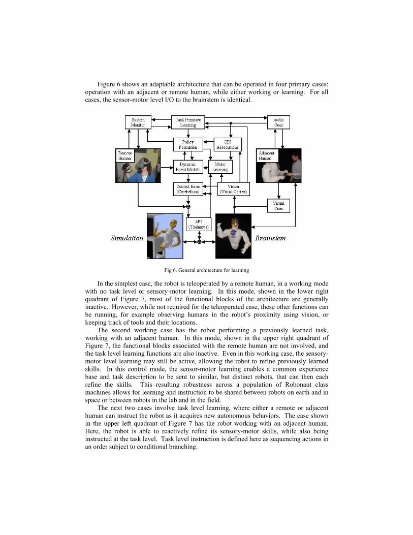
Figure 6 shows an adaptable architecture that can be operated in four primary cases: operation with an adjacent or remote human, while either working or learning. For all cases, the sensor-motor level I/O to the brainstem is identical.
Fig 6. General architecture for learning
In the simplest case, the robot is teleoperated by a remote human, in a working mode with no task level or sensory-motor learning. In this mode, shown in the lower right quadrant of Figure 7, most of the functional blocks of the architecture are generally inactive. However, while not required for the teleoperated case, these other functions can be running, for example observing humans in the robot’s proximity using vision, or keeping track of tools and their locations.
The second working case has the robot performing a previously learned task, working with an adjacent human. In this mode, shown in the upper right quadrant of Figure 7, the functional blocks associated with the remote human are not involved, and the task level learning functions are also inactive. Even in this working case, the sensory-motor level learning may still be active, allowing the robot to refine previously learned skills. In this control mode, the sensor-motor learning enables a common experience base and task description to be sent to similar, but distinct robots, that can then each refine the skills. This resulting robustness across a population of Robonaut class machines allows for learning and instruction to be shared between robots on earth and in space or between robots in the lab and in the field.
The next two cases involve task level learning, where either a remote or adjacent human can instruct the robot as it acquires new autonomous behaviors. The case shown in the upper left quadrant of Figure 7 has the robot working with an adjacent human. Here, the robot is able to reactively refine its sensory-motor skills, while also being instructed at the task level. Task level instruction is defined here as sequencing actions in an order subject to conditional branching.
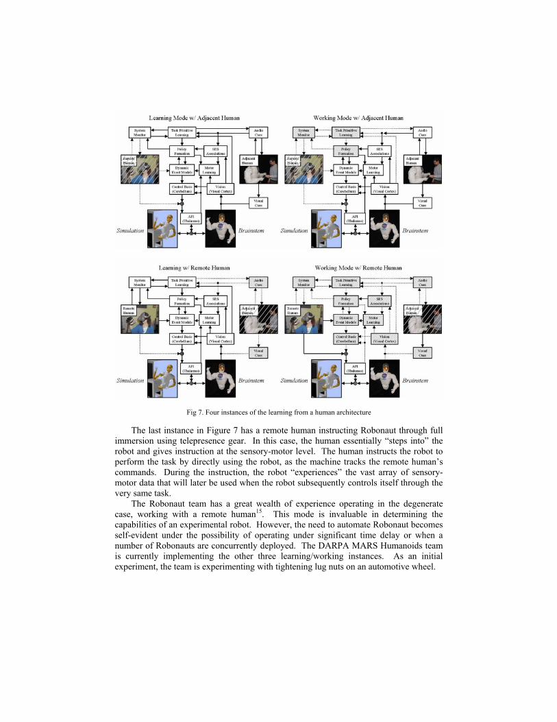
Fig 7. Four instances of the learning from a human architecture
The last instance in Figure 7 has a remote human instructing Robonaut through full immersion using telepresence gear. In this case, the human essentially “steps into” the robot and gives instruction at the sensory-motor level. The human instructs the robot to perform the task by directly using the robot, as the machine tracks the remote human’s commands. During the instruction, the robot “experiences” the vast array of sensory-motor data that will later be used when the robot subsequently controls itself through the very same task.
The Robonaut team has a great wealth of experience operating in the degenerate case, working with a remote human15. This mode is invaluable in determining the capabilities of an experimental robot. However, the need to automate Robonaut becomes self-evident under the possibility of operating under significant time delay or when a number of Robonauts are concurrently deployed. The DARPA MARS Humanoids team is currently implementing the other three learning/working instances. As an initial experiment, the team is experimenting with tightening lug nuts on an automotive wheel.

3. Approach
To bring together an interdisciplinary team of researchers presents quite a number of challenges. Each team member brings different skills bases and preferences ranging from the most important issues on humanoid research to operating systems to programming languages and working hours. As the project began, the strengths of each group were considered in order that the correct roles and inter-group synergies could be exploited. From these discussions, the following roles were defined:
• University of Massachusetts – Grasping and understanding operator’s intent • Vanderbilt University/University of Southern California – Sensory egosphere
(Vanderbilt), superposition of behaviors, learned through teleoperation • Massachusetts Institute of Technology/Naval Research Lab – Spatial reasoning,
language understanding, social interaction, perspective taking • Johnson Space Center – Stereo vision, sensing based behaviors, integration
3.1. Autonomous capabilities and autonomy enabling functions
At the core of the autonomous behaviors is a variety of low-level behaviors and sensing modalities. Behaviors include guarded movements, pointing to a location, reflexive grasping, tracking objects seen with the vision system, servoing the neck to look or follow a position, impedance and damping control laws, and the ability to "speak". Sensing functions include six-axis load cells at both the shoulders and wrists, tactile sensing in the hands, proprioception, stereo vision and the ability to hear. Note that speaking and hearing are not applicable modes in the vacuum of space, but serve as important functions of terrestrial versions of Robonaut.
3.1.1 Sensory egosphere
Robonaut uses a data structure called the Sensory Egosphere (SES) as common short-term memory and networked scratch space between processes. In this capacity, the SES is being underutilized on Robonaut. In its designed form, the SES stores and tracks the location of known objects in an egocentric manner, allowing the robot to better understand its environment by searching memory for data or objects by region, name, class, etc.16
3.1.2. Stereo vision
Good stereo vision is central to the performance of Robonaut as a human's assistance and tool user17. The stereo vision system employs a pair of head-mounted commercial cameras, pointed by the driving the robot's neck. The Robonaut vision system performs object recognition and pose estimation enabling the robot to perform practical tasks in real-world domains, e.g. tracking multiple complex objects, cluttered foregrounds and backgrounds, and partially occluded objects
The vision system employs Laplacian of Guassian (LoG) pre-filtering making the correlation process sensitive to natural surface (visual) texture. After building the range maps, they are then thresholded to produce a binary range map (a 2D silhouette map). Each element of the binary map gets a 1 for object surfaces detected within a range of

interest and a 0 if not –revealing silhouettes of object within the range. The silhouettes are then matched against increasingly higher fidelity templates, Figure 8. The silhouette maps reliably and accurately measure three of six pose parameters. The three other (out of image plane) parameters are matched against 3D range information tagged to the 2D silhouettes, Figure 9.
Fig 8. Matching against increasingly higher fidelity silhouette templates
Fig 9. Matching tagged points against 3D range information
3.1.3. Learning through teleoperation
Figure 7 describes four instances of learning and working with adjacent and remote humans. The lower left instance shows learning with a remote human. In this case, a teleoperator in full immersion commands the robot to perform a task while the robot observes its own sensory-motor commands. By observing a number of trials, the learning system can superposition a small set of behaviors, leading to the completion of a complex task18.
Four phases exist for the data gathering and analysis for this learning through teleoperation. First, a teleoperator controls the robot through the desired tasks. As the teleoperator performs these training motions, Robonaut’s sensory data and motor command streams are sampled and recorded as a time-series. Next, the sensory-motor coordination (SMC) events are used to parse the operations into episodes. The signals are then averaged at each location to produce a canonical, sensory-motor data, vector time-series for each location. Finally, the verbs and adverbs process combine the generalized motions19. Once the generalized motions are created, they serve as a general representation of the task. Under runeal-time conditions, the representation guides the task towards completion (verbs), while sensory data modifies the execution of the task towards the goal (adverbs) and delineates the episodic boundaries. Subjectively, trajectories executed using learning through teleoperation are unique because the teleoperator's style (pauses, approach directions, using visual cues to gauge quality of task completion, etc.) is evident in ways that would not occur to a programmer hard coding a motion.

3.1.4. Spatial reasoning system
Robonaut employs a spatial reasoning system to detect the intersection of forearm deictic gestures with the plane of an object residing within the sensory egosphere. While generic in nature, the system on Robonaut determines the intersection of the forearm pointing gestures with the plane of the wheel, both originally detected by the vision system, and then correlates in memory the order of tightening lug nuts prescribed by the adjacent human.
When correlating the adjacent human's wishes to the sensory data, the system must take into account several difficulties that arise from the data collection. First, the robot's vision sensor produces a noisy estimation of the actual human forearm orientation. The vision system also has difficulty gauging the range when matching silhouettes to templates due to the variations in the size and shape of human arms and hands. Second, since the human arm is not aligned with the human eye, visually guided human pointing introduces a target error proportional with the distance of the destination being pointed at. Since the discrimination distances between the nuts are so small (radius ~3cm), these errors can frequently be larger than the distances themselves. Just as humans observe relative information from multiple gestures to determine the correct pattern, Robonaut's spatial reasoning system makes similar inferences.
After projecting the pointing data onto the wheel plane, the spatial reasoning system employs a nearest neighbor’s algorithm to match the intersection points to the appropriate nuts. The heuristic that any human error is more likely to manifest itself from a lower level mechanical source (pointing accuracy) than a higher-level task source (mislabeling a nut) is employed. Therefore, an exhaustive nearest neighbor search of the labeling space produces matches that are optimal in terms of minimizing the residual spatial error.
For feedback to the operators and as a development tool, the spatial reasoning system incorporates a 3-D viewer that graphically displays the spatial arrangements of the various objects relative to the robot, as well as an arbitrary number of user-defined vectors and polygons, from the viewpoint of a controllable virtual camera. An example screenshot is shown in Figure 10 over the shoulder of the stick-figure Robonaut, with the wheel displayed as a blue cylinder, the nuts as red cubes, the forearm gestures as thick multicolored lines and the gesture labels as green pyramids. The thin multicolored lines show the assignments of the labels to nuts, passing through a vertex point representing their locations as corrected for the estimated systematic pointing error.
3.1.5. Grasping
In traditional robotics, a standard technique used to place nut drivers onto nuts is to first place cameras at strategic locations; either along the insertion axis or orthogonal to the task to optimize the quality of viewing, then change out the tooling with a nut driver. Robonaut misses on both these points in that it does not require these specialized actions. First, the cameras are attached to the robot, in roughly the same location and with similar kinematics relative to the body as a human. Next, when the robot picks up a tool, that tool is not rigidly held. The transformation between the hand and tool tip does not remain constant. This leads to the need to automatically re-calibrate the pose of the drill in the hand periodically.

Fig 10. Spatial reasoning graphical output
During the lug nut tightening task, the nut driver will typically be placed in a holster within the robot's reach. To grasp the drill, four basic grasping behaviors are used to form the drill grasp policy. There is a primitive for moving the hand around the drill handle, another for putting the thumb on the back of the drill handle, another for putting the index finger on the trigger, and finally one for putting the rest of the palm against the handle and closing the fingers20.
The grasp policy was developed through observation of the kind of grasps used by teleoperators when grasping the drill. It was determined that many good drill grasps placed the base of the inner thumb against the outside of the drill handle. This inspired a grasp primitive that moved the hand until a positive force was registered on the tactile sensor at the base of the inner thumb, Figure 11.
Fig 11. Grasping the nut driver, looking for contact at base of thumb
Another main requirement for the drill grasp is that the index finger be able to actuate the trigger. Therefore, the next grasp primitive moves the hand up and down
along the axis of the handle until the index finger opposes the trigger. The primitive iteratively closes the index finger on the handle until the index finger moves down off the barrel onto the trigger in a single step.
At this point in the process, the handle and trigger are positioned between the base of the thumb and index finger. The next primitive rolls the hand about the axis between thumb and index finger. The roll continues until contact with the glove sensors at the bottom of the hand is perceived.
Finally, after satisfactorily navigating the proper states within a finite state machine (FSM), the grasp controller closes the hand, extracts the drill from the holster and tests the quality of grasp by closing the trigger.
3.2. Integrated demonstration
The initial integrated task for the team is to tighten lug nuts on an automotive wheel using a bolt driver. While seemingly very straightforward, it is a task that requires many relevant humanoid topics, including human-robot interactions, grasping, learning, teaching, spatial reasoning, and stereo vision.
As an example of the complexity of this task, consider how a human performs the task for the first time. A 16-year-old human beginning work as a tire changer for the first time in an automotive shop possesses many of the behaviors needed to complete the task of performing the lug nut tightening task. They know from experience how to pick up a pneumatic nut driver, because it is very similar to their parent’s drill. After acquiring the nut driver, the junior mechanic takes a look at the wheel, then visually servos the socket towards the first nut. Once contact occurs, the visual servo control mode changes into a force control task that aligns the socket until it bottoms out on the lug nut. At this point, the shoulder becomes a bit strained, so they adjust their body so the arm is more comfortable and has better leverage. The novice then pulls the trigger and the lug nut begins to spin. After a few turns of the nut, it tightens, indicated by the torque felt in the arm. Next, the trigger is released and the nut driver is pulled off the nut.
Moving on, the first timer intuitively begins to repeat the process starting with a visual servo to the next nut in a clockwise pattern. At this point, the supervisor, who’s been watching all along, interrupts for a dose of human-human interaction. After verbally gaining the trainee’s attention, the supervisor asks them to stop. The supervisor then indicates that the proper way to put the wheel back on the car is tighten the nuts in a star, pattern, saying as he points, “First you do this one, then this one, then this one…” The rookie, says “OK”, and then completes the other four loose lug nuts. When the next car into the shop has a six-bolt pattern, the 16-year-old either asks the supervisor how to do the new task or generalizes that it can be done similarly to the already known task.
Because Robonaut has neither the experience base nor the cognitive abilities of the 16-year-old mechanic-in-training, its human partners do not make the same assumptions as the supervisor did in the example.
A typical work session begins by the adjacent human greeting the robot using a combination of off-the-shelf voice recognition software and NAUTILUS, the Naval Research Laboratory’s natural language understanding parser21. This greeting grabs the attention of Robonaut, which triggers a behavior to find then track its human partner. As part of the greeting trigger, Robonaut clears its knowledge of the task data from its SES.
In the working with tools scenario, a controller that finds and tracks the human fist and forearm triggers when the adjacent human steps within a 1.5 meter radius of the
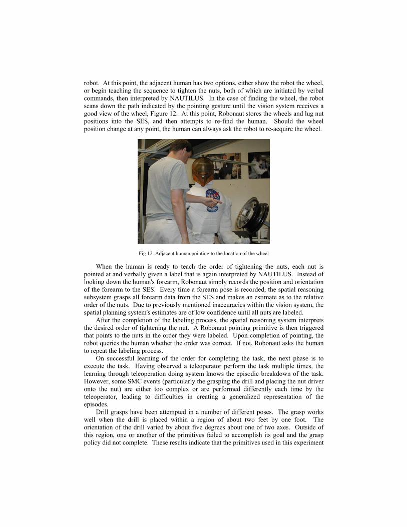
robot. At this point, the adjacent human has two options, either show the robot the wheel, or begin teaching the sequence to tighten the nuts, both of which are initiated by verbal commands, then interpreted by NAUTILUS. In the case of finding the wheel, the robot scans down the path indicated by the pointing gesture until the vision system receives a good view of the wheel, Figure 12. At this point, Robonaut stores the wheels and lug nut positions into the SES, and then attempts to re-find the human. Should the wheel position change at any point, the human can always ask the robot to re-acquire the wheel.
Fig 12. Adjacent human pointing to the location of the wheel
When the human is ready to teach the order of tightening the nuts, each nut is pointed at and verbally given a label that is again interpreted by NAUTILUS. Instead of looking down the human's forearm, Robonaut simply records the position and orientation of the forearm to the SES. Every time a forearm pose is recorded, the spatial reasoning subsystem grasps all forearm data from the SES and makes an estimate as to the relative order of the nuts. Due to previously mentioned inaccuracies within the vision system, the spatial planning system's estimates are of low confidence until all nuts are labeled.
After the completion of the labeling process, the spatial reasoning system interprets the desired order of tightening the nut. A Robonaut pointing primitive is then triggered that points to the nuts in the order they were labeled. Upon completion of pointing, the robot queries the human whether the order was correct. If not, Robonaut asks the human to repeat the labeling process.
On successful learning of the order for completing the task, the next phase is to execute the task. Having observed a teleoperator perform the task multiple times, the learning through teleoperation doing system knows the episodic breakdown of the task. However, some SMC events (particularly the grasping the drill and placing the nut driver onto the nut) are either too complex or are performed differently each time by the teleoperator, leading to difficulties in creating a generalized representation of the episodes.
Drill grasps have been attempted in a number of different poses. The grasp works well when the drill is placed within a region of about two feet by one foot. The orientation of the drill varied by about five degrees about one of two axes. Outside of this region, one or another of the primitives failed to accomplish its goal and the grasp policy did not complete. These results indicate that the primitives used in this experiment
generalize over only a small set of initial positions and orientations. By making the primitives more generalizable, it may be possible to generalize over a wider range of initial drill poses. Nevertheless, as long as it can be assured that the drill holster will be placed inside this capture envelope, then the grasp policy will execute with good probability.
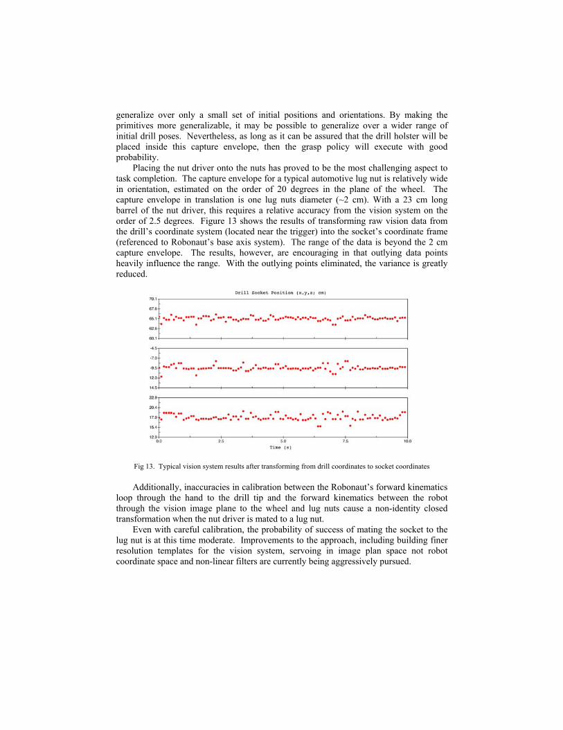
Placing the nut driver onto the nuts has proved to be the most challenging aspect to task completion. The capture envelope for a typical automotive lug nut is relatively wide in orientation, estimated on the order of 20 degrees in the plane of the wheel. The capture envelope in translation is one lug nuts diameter (~2 cm). With a 23 cm long barrel of the nut driver, this requires a relative accuracy from the vision system on the order of 2.5 degrees. Figure 13 shows the results of transforming raw vision data from the drill’s coordinate system (located near the trigger) into the socket’s coordinate frame (referenced to Robonaut’s base axis system). The range of the data is beyond the 2 cm capture envelope. The results, however, are encouraging in that outlying data points heavily influence the range. With the outlying points eliminated, the variance is greatly reduced.
Fig 13. Typical vision system results after transforming from drill coordinates to socket coordinates
Additionally, inaccuracies in calibration between the Robonaut’s forward kinematics loop through the hand to the drill tip and the forward kinematics between the robot through the vision image plane to the wheel and lug nuts cause a non-identity closed transformation when the nut driver is mated to a lug nut.
Even with careful calibration, the probability of success of mating the socket to the lug nut is at this time moderate. Improvements to the approach, including building finer resolution templates for the vision system, servoing in image plan space not robot coordinate space and non-linear filters are currently being aggressively pursued.
4. Forward Work
The task described in section 3.2 is a snapshot of the work currently under way by the DARPA MARS Humanoids team. At this writing, much of the subsystem engineering required to perform this task is finished. However, integration of the teaching the order to drive the nuts, pulling the drill out of the holster, and tightening the nuts is not fully complete.
Even after the completion of this work, Robonaut will still be lacking many needed skills. A large step towards the continued evolution of Robonaut’s “mind” will be further integrating the state-of-the-art research coming out of the university laboratories.
The learning by being shown the order of task execution is a very shallow form of learning. To become a truly autonomous tool user, the task sequence must be represented in a more generalized manner. The MIT team has successfully explored teaching their humanoid robot, Leonardo, how to perform a generalized task through tutelage22,23. Building on the ability of Robonaut to perform actions on objects in the world, the next endeavor involves the ability for a human to teach the robot more complex tasks made up of these actions. To allow this, human-robot communication must extend beyond labeling objects for the robot and requesting subsequent actions to be performed on them. Technology to have the robot learn a generalized task representation that includes object properties and goals must be implemented. Ideally, Robonaut would be able to learn a generalized task representation through working through several examples with a human instructor. After the task is learned, Robonaut should then be able to perform the task on a different wheel, with a different number of bolts to be tightened, where the bolts might be arranged in a different pattern.
The group at the University of Massachusetts is pursuing research down two paths, using their humanoid, Dexter, that when transferred to Robonaut will greatly increase its skill base. The first pursuit is implementing more generalized grasping controllers that can be used to grasp the nut driver or objects in general.
While robotic grasping research typically assumes that fingertips alone will be used to grasp objects, non-fingertip contacts are also possible. For example, potential contact points may exist along the entire surface of a finger not just at the fingertip. Grasps that depend on non-fingertip contacts on arbitrary hand and body surfaces may be termed “whole body grasp”. Unfortunately, synthesizing whole body grasps can be difficult because kinematic coupling among non-fingertip contacts may prevent desired contact points from being made. Therefore, manipulator kinematics must be considered when synthesizing grasps.
One method manipulator kinematics can inform the grasp search process is through the use of “virtual fingers.” A virtual finger is a set of fingers or other hand/arm surfaces that provide a single oppositional force24. For example, humans often use their four fingers as a single virtual finger in opposition to the thumb. Similarly, virtual fingers are used to synthesize an enveloping grasp for the Robonaut hand. Position and normal information from multiple physical contacts on the Robonaut hand fingertips are grouped together and averaged. To enable the integration of the UMass grasping work, the Robonaut team is developing fingertip force sensing that allow localization of contact and surface normals.
The second research area being pursued by the Umass team involves learning by predicting operator intent during teleoperation. Figure 14 shows the predictor display for a tool-use experiment with Dexter. In this experiment, predictions of operator intent are

based on movement of the robot in the vicinity of key landmarks, i.e., bolts in the figure. In particular, the predictions about which bolt to tighten are simply a function of the position and velocity of the end-effector, relative to each bolt. The operator controls the drill using hand movements with a glove-like input device.
Fig 14. The Umass humanoid Dexter using predictive displays to understand operator intent
With the proper feedback from the predictor display, the teleoperator has an effective means for adjusting commands to elicit the desired prediction from the interface. In other words, the operator has two strategies for tightening a bolt: (1) carefully move the robot toward the target bolt and then engage an autonomous docking controller; or (2) exploit the interface by first moving to a region of space where the target bolt is easily discriminated from the others, and then engage the docking controller. Anecdotal evidence shows that the latter strategy is extremely effective, and in many cases the operator can use gross movements for precise target selection. Applied to learning, this approach will provide additional composite data to the learning through teleoperation techniques
Lastly, the learning from the remote teleoperator groups at Vanderbilt and USC are investigating methods to better automate the processes of segmenting new data and building generalized presentations of tasks.
Conclusions
This paper describes an on-going integration effort between members of the DARPA MARS Humanoids team. It highlights work being conducted on NASA JSC's Robonaut humanoid in an often overlooked area of humanoid research, working with tools, specifically tightening the nuts on an automotive wheel. This work presents the beginning of an evolution from a purely teleoperated machine towards a full autonomous tool using humanoid. To achieve this goal, continued development will need to proceed by advancing the state-of-the-art in humanoid mechanical systems, cognitive development, advanced sensing, and the more traditional robotics control systems. Until capable of working with their hands, humanoids will continue to develop, but will not be fully functional.
Acknowledgements
NASA and the Mobile Autonomous Robot Software (MARS) program in the DARPA Information Processing Technology Office (IPTO) sponsored this work.
References
1. Y. Sakagami, R. Watanabe, C. Aoyama, S. Matsunaga., N. Higaki, K. Fujimura, “The intelligent ASIMO: system overview and integration,”, Proceedings of the 2002 IEEE/RSJ International Conference on Intelligent Robots and Systems, 2002, pp 2478-2483.
2. M. Fujita, Y. Kuroki, T. Ishida, T. Doi, ” A small humanoid robot SDR-4X for entertainment applications,” Proceedings of the 2003 IEEE/ASME International Conference on Advanced Intelligent Mechatronics, 2003, pp. 938–943.
3. F. Yamasaki, T. Matsui, T. Miyashita, H. Kitano, “PINO – The Humanoid that Walks,” Proceedings of the First IEEE-RAS International Conference on Humanoid Robots, 2000.
4. K. Kaneko, F. Kanehiro, S. Kajita, K. Yokoyama, K. Akachi, T. Kawasaki, S. Ota, T. Isozumi, “Design of prototype humanoid robotics platform for HRP,” Proceedings of the 2002 IEEE/RSJ International Conference on Intelligent Robots and Systems, 2002, pp. 2431-2436.
5. R. Brooks, C. Breazeal, M. Marjanovic, B. Scassellati, M. Williamson, “The Cog Project: Building a Humanoid Robot” Computation for Metaphors, Analogy, and Agents. C. Nehaniv (ed), Lecture Notes in Artificial Intelligence 1562. New York, Springer, 1999, pp. 52–87.
6. C. Breazeal, "Towards sociable robots," T. Fong (ed), Robotics and Autonomous Systems, 42(3-4), 2003, pp. 167-175.
7. R. Ambrose, C. Ambrose, “Primate Anatomy, Kinematics and the Principles for Humanoid Design,” International Journal of Humanoid Robotics, Vol. 1, No. 1, 2004, pp. 175-198.
8. G. Hirzinger, B. Brunner, J. Dietrich, J. Heindl, “ROTEX–The First Remotely Control Robot in Space, IEEE International Conference on Robotics and Automation,” 1994, pp 2604–2611.
9. M. Oda, “ETS-VII: Achievements, Troubles, and Future,” Proceedings of the 6th International Symposium on Artificial Intelligence and Robotics & Automation in Space: I-SAIRAS 2001, 2001.
10. Extravehicular Activity (EVA) Hardware Generic Design Requirements Document, JSC 26626, NASA/Johnson Space Center, Houston, Texas, 1994.
11. C. Lovchik, M. Diftler, “Compact Dexterous Robotic Hand.” United States Patent #6,244,644, 2001.
12. F. Rehnmark, W. Bluethmann, I. Spain, S. Goza, R. Ambrose, K. Alder, “An Experimental Investigation of Robotic Spacewalking, submitted to Humanoids 2004.
13. R. Ambrose, R. Savely, S. Goza, P. Strawser, M. Diftler, I. Spain, N. Radford, “Mobile Manipulation using NASA’s Robonaut,” Proceedings in the 2004 Conference on Robotics and Automation, 2004.
14. Albus, J., “A Theory of Cerebellar Function,” Mathematical Biosciences, 10, 1971, pp. 25-61. 15. R. Ambrose, C. Culbert, F. Rehnmark, “An Experimental Investigation of Dexterous Robots
working with EVA Hardware”, AIAA Space 2001, 2001. 16. K. Kawamura R. Peters, C., Johnson P., Nilas S. Thongchai, “Supervisory control of mobile
robots using Sensory EgoSphere”, Proceedings 2001 IEEE International Symposium on Computational Intelligence in Robotics and Automation, 2001, pp. 523 – 529.
17. E. Huber, K. Baker, “Using a Hybrid of Silhouette and Range Templates for Real-time Pose Estimation,” Proceedings of the 2004 International Conference on Robotics and Automation, ICRA 2004, 2004.
18. C. Campbell, R. Peters, R. Bodenheimer, W. Bluethmann, E. Huber, R. Ambrose, “Superpositioning of Behaviors Learned through Teleoperation,” accepted to IEEE Transactions on Robotics and Automation, 2004.
19. Rose, C., M. Cohen, and B. Bodenheimer, “Verbs and Adverbs: Multidimensional Motion Interpolation”, IEEE Computer Graphics and Applications, Vol. 18, No. 5, 1998, pp. 32-40.
20. T. Martin, R. Ambrose, M. Diftler, R. Platt, M.Butzer, "Tactile Gloves for Autonomous Grasping with the NASA/DARPA Robonaut," Proceedings of the 2004 International Conference on Robotics and Automation, ICRA 2004, 2004.
21. K. Wauchope, “Eucalyptus: Integrating Natural Language Input with a Graphical User Interface,” Naval Research Laboratory Technical Report NRL/FR/5510-94-9711, 1994.

22. C. Breazeal, A. Brooks, D. Chilongo, J. Gray, G. Hoffman, C. Kidd, H. Lee, J. Lieberman, A. Lockerd,“Humanoid Robots as Cooperative Partners for People,” To appear International Journal of Humanoid Robots, 2004.
23. C. Breazeal, G. Hoffman, A. Lockerd, “Teaching and Working with Robots as a Collaboration,” To appear AAMAS 2004, 2004.
24. T. Iberall; G. Sukhatme; D. Beattie, G. Bekey, “Control philosophy and simulation of a robotic hand as a model for prosthetic hands,” Proceedings of the 2002 IEEE/RSJ International Conference on Intelligent Robots and Systems,1993, pp. 824–831.
![Design of an Autonomous Humanoid Robot - Yolarobozires.yolasite.com/resources/10[1].1.1.94.1237.pdf · This paper describes the design of an autonomous humanoid robot. The robot itself](https://static.fdocuments.in/doc/165x107/5b7c12eb7f8b9a70138beaed/design-of-an-autonomous-humanoid-robot-111941237pdf-this-paper-describes.jpg)
![Future Research Perspectives With Autonomous, Intelligent Humanoid Robots [Presentation at EYE Lab Surfing Workshop]](https://static.fdocuments.in/doc/165x107/55944d761a28ab596f8b46bb/future-research-perspectives-with-autonomous-intelligent-humanoid-robots-presentation-at-eye-lab-surfing-workshop.jpg)

![From Vision to Actions - Towards Adaptive & Autonomous Humanoid Robots [PhD Defense]](https://static.fdocuments.in/doc/165x107/547e7784b4af9fb9158b56ca/from-vision-to-actions-towards-adaptive-autonomous-humanoid-robots-phd-defense.jpg)