
BUILD-MASTER - ensoftsystems.com · A shear wall can be idealized in Build-master as follows-- A...
167
Transcript of BUILD-MASTER - ensoftsystems.com · A shear wall can be idealized in Build-master as follows-- A...
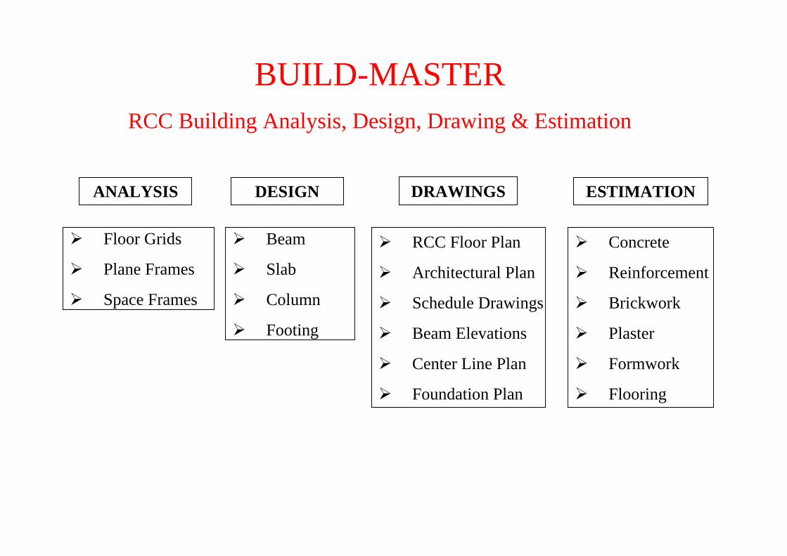
BUILD-MASTERRCC Building Analysis, Design, Drawing & Estimation
ANALYSIS DESIGN DRAWINGS ESTIMATION
Floor Grids
Plane Frames
Space Frames
Beam
Slab
Column
Footing
RCC Floor Plan
Architectural Plan
Schedule Drawings
Beam Elevations
Center Line Plan
Foundation Plan
Concrete
Reinforcement
Brickwork
Plaster
Formwork
Flooring

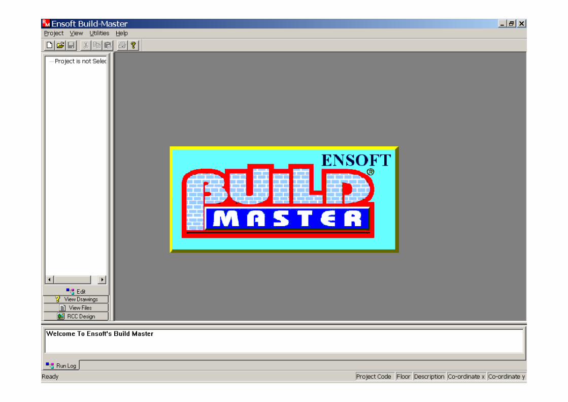
The step by step Analysis and Design of a Multistoried Building with 3 lifts and a staircase is shown here.
The step by step Analysis and Design of a Multistoried Building with 3 lifts and a staircase is shown here.
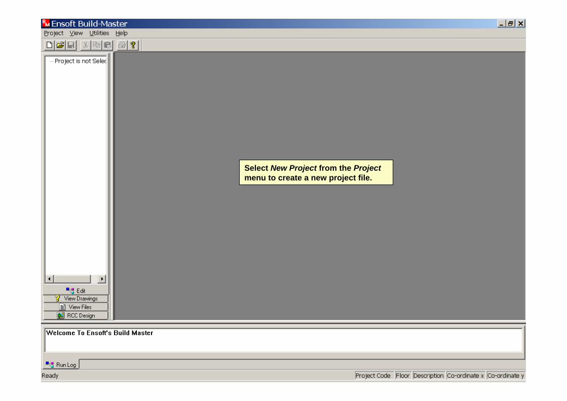
Select New Project from the Project menu to create a new project file.
Select New Project from the Project menu to create a new project file.

It is mandatory to enter 4 characters Project code, as Build-Master later creates files for various floors by appending floor names to it .
Enter no. of floors, storey height and Project title then click ok.
It is mandatory to enter 4 characters Project code, as Build-Master later creates files for various floors by appending floor names to it .
Enter no. of floors, storey height and Project title then click ok.
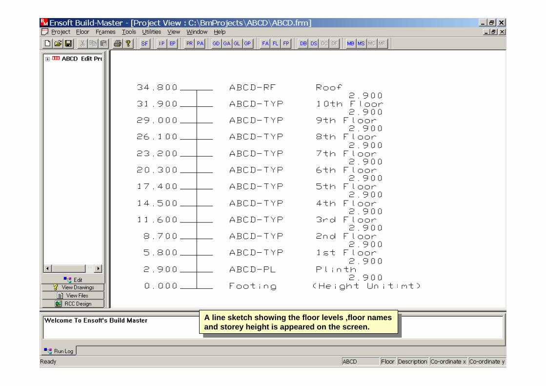
A line sketch showing the floor levels ,floor names and storey height is appeared on the screen.
A line sketch showing the floor levels ,floor names and storey height is appeared on the screen.
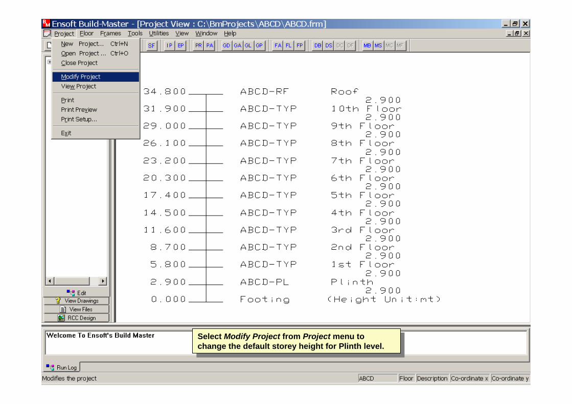
Select Modify Project from Project menu to change the default storey height for Plinth level.
Select Modify Project from Project menu to change the default storey height for Plinth level.
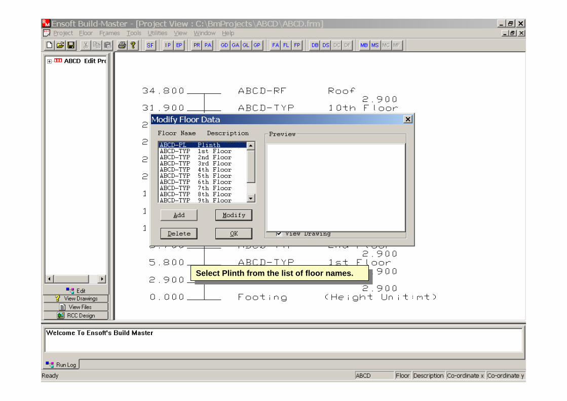
Select Plinth from the list of floor names.Select Plinth from the list of floor names.

Change Storey height to desired value and click OK.Change Storey height to desired value and click OK.

Again the line sketch with changed height for the Plinth floor is displayed.
Again the line sketch with changed height for the Plinth floor is displayed.
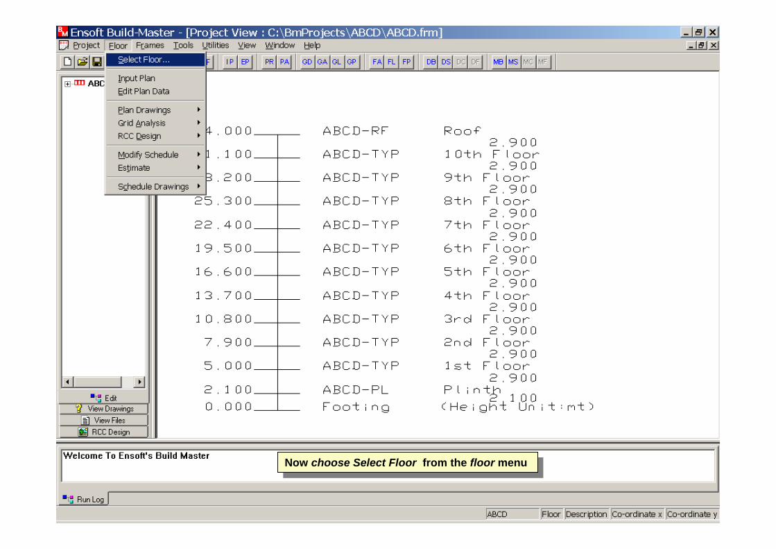
Now choose Select Floor from the floor menu Now choose Select Floor from the floor menu

Select the desired floor then click Select.Select the desired floor then click Select.
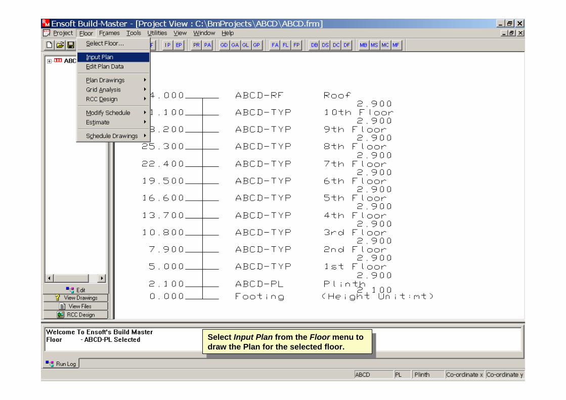
Select Input Plan from the Floor menu to draw the Plan for the selected floor.
Select Input Plan from the Floor menu to draw the Plan for the selected floor.
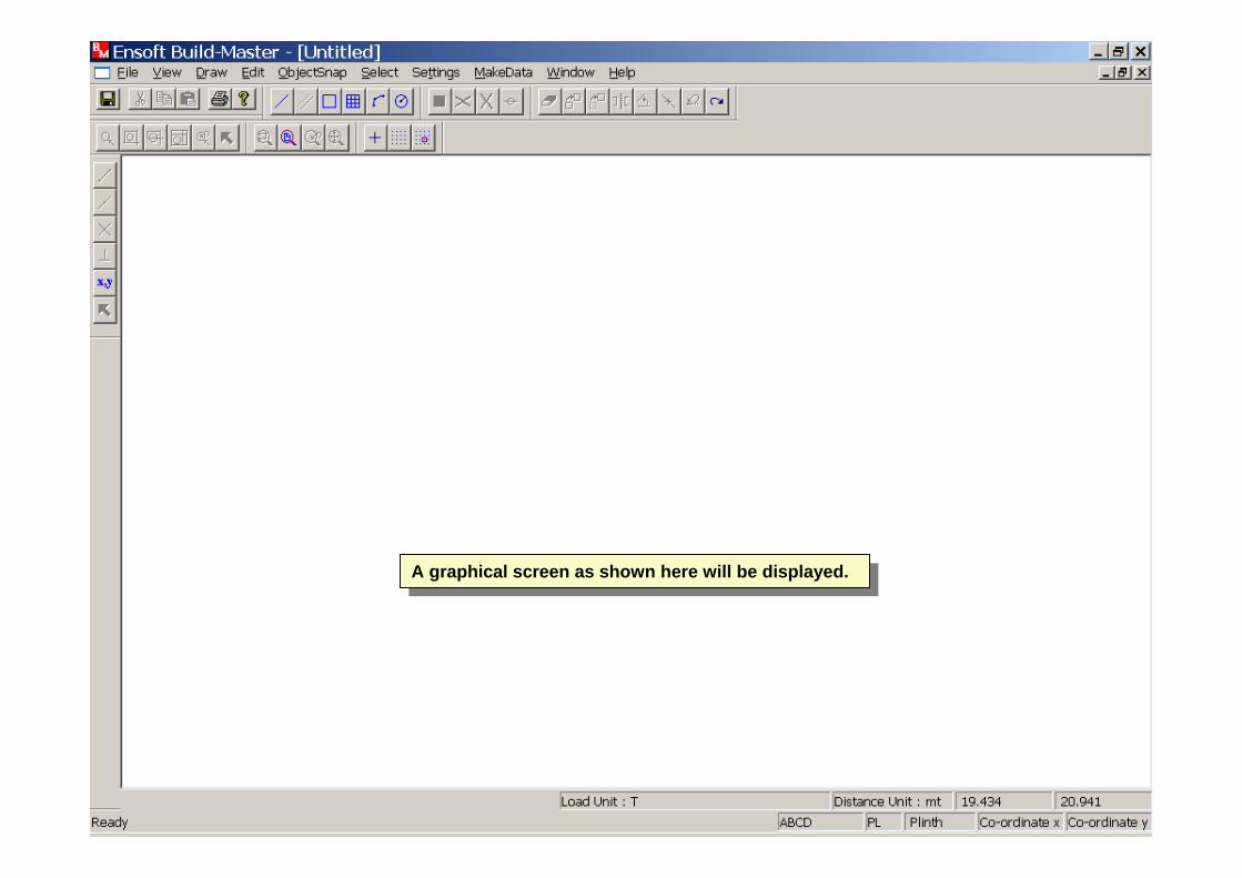
A graphical screen as shown here will be displayed.A graphical screen as shown here will be displayed.
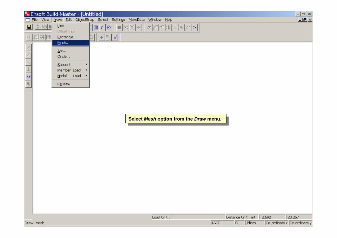
Select Mesh option from the Draw menu.Select Mesh option from the Draw menu.

The spacing in X and Y directions are not same, hence select New Random from the Spacing Type and click on Random Mesh.
The spacing in X and Y directions are not same, hence select New Random from the Spacing Type and click on Random Mesh.

Enter the X values by using Add Row button.
No. of X values is equal to no. of X grids.
Enter the X values by using Add Row button.
No. of X values is equal to no. of X grids.
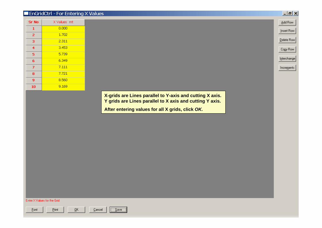
X-grids are Lines parallel to Y-axis and cutting X axis. Y grids are Lines parallel to X axis and cutting Y axis.
After entering values for all X grids, click OK.
X-grids are Lines parallel to Y-axis and cutting X axis. Y grids are Lines parallel to X axis and cutting Y axis.
After entering values for all X grids, click OK.
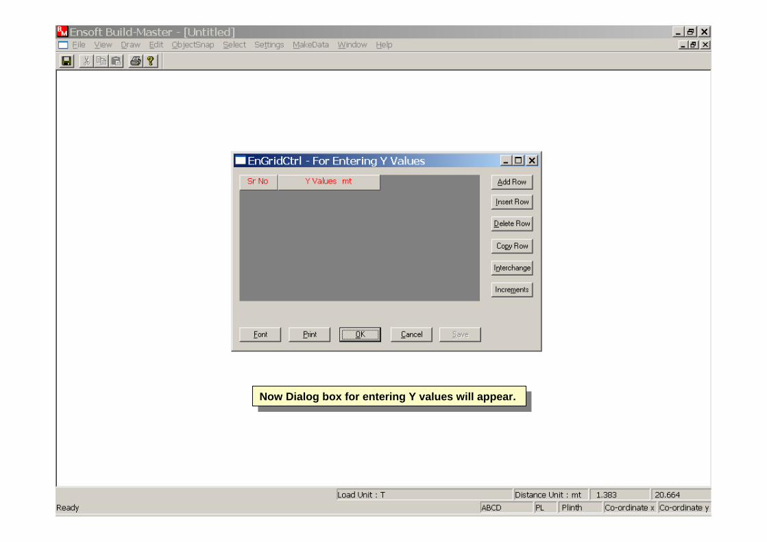
Now Dialog box for entering Y values will appear.Now Dialog box for entering Y values will appear.

After entering all Y values click Ok.After entering all Y values click Ok.
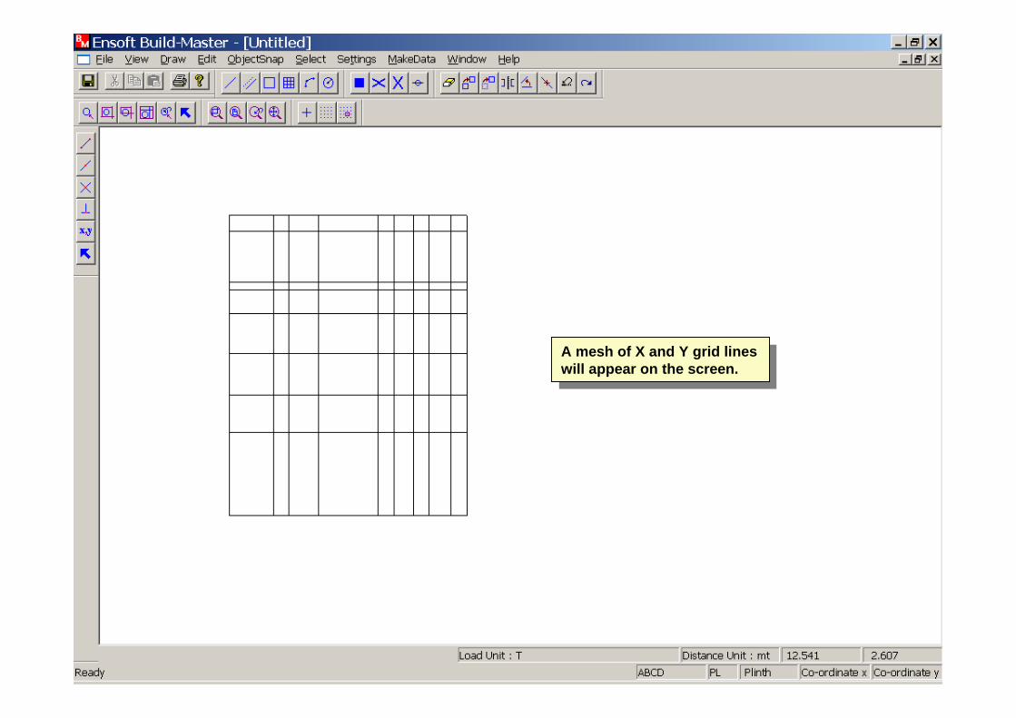
A mesh of X and Y grid lines will appear on the screen.
A mesh of X and Y grid lines will appear on the screen.

Now select Erase from the Edit menu.Now select Erase from the Edit menu.
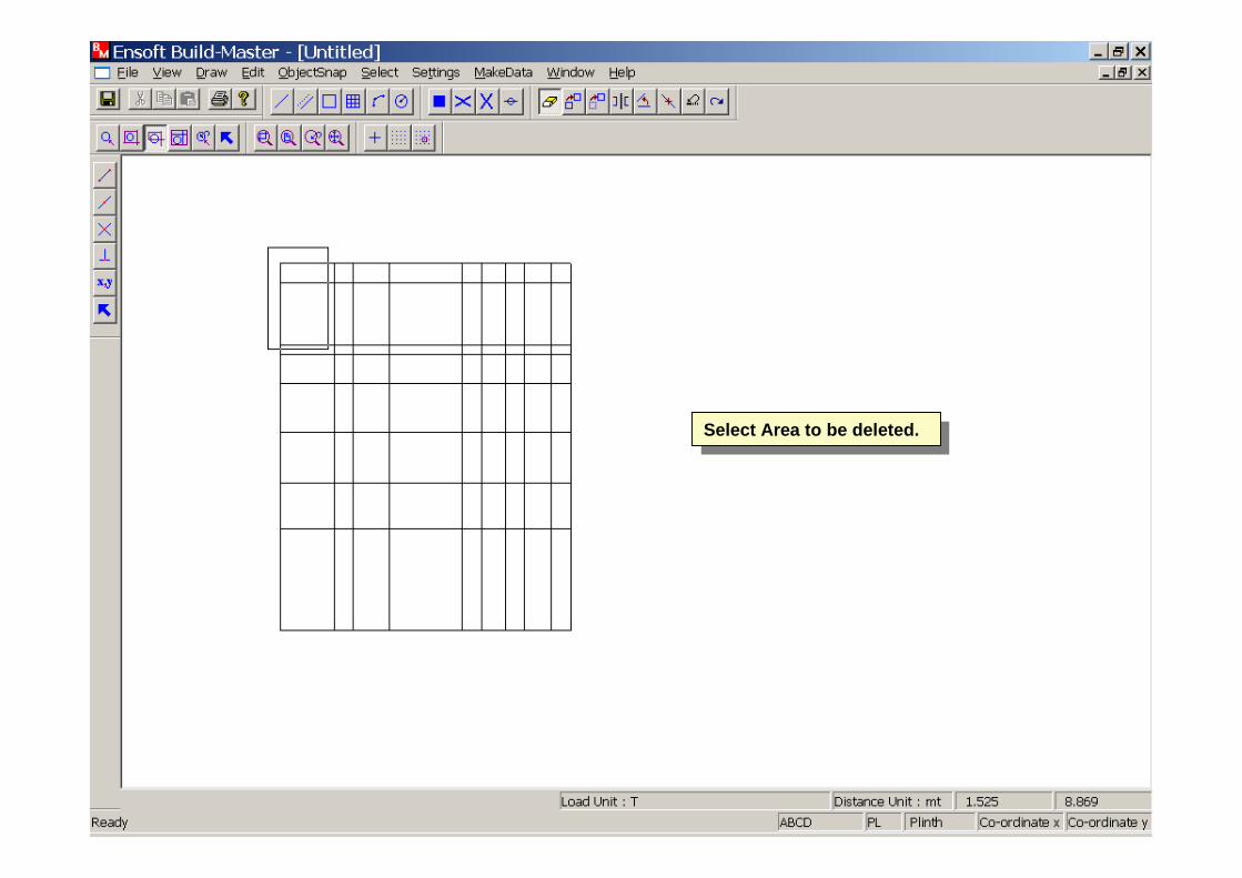
Select Area to be deleted.Select Area to be deleted.


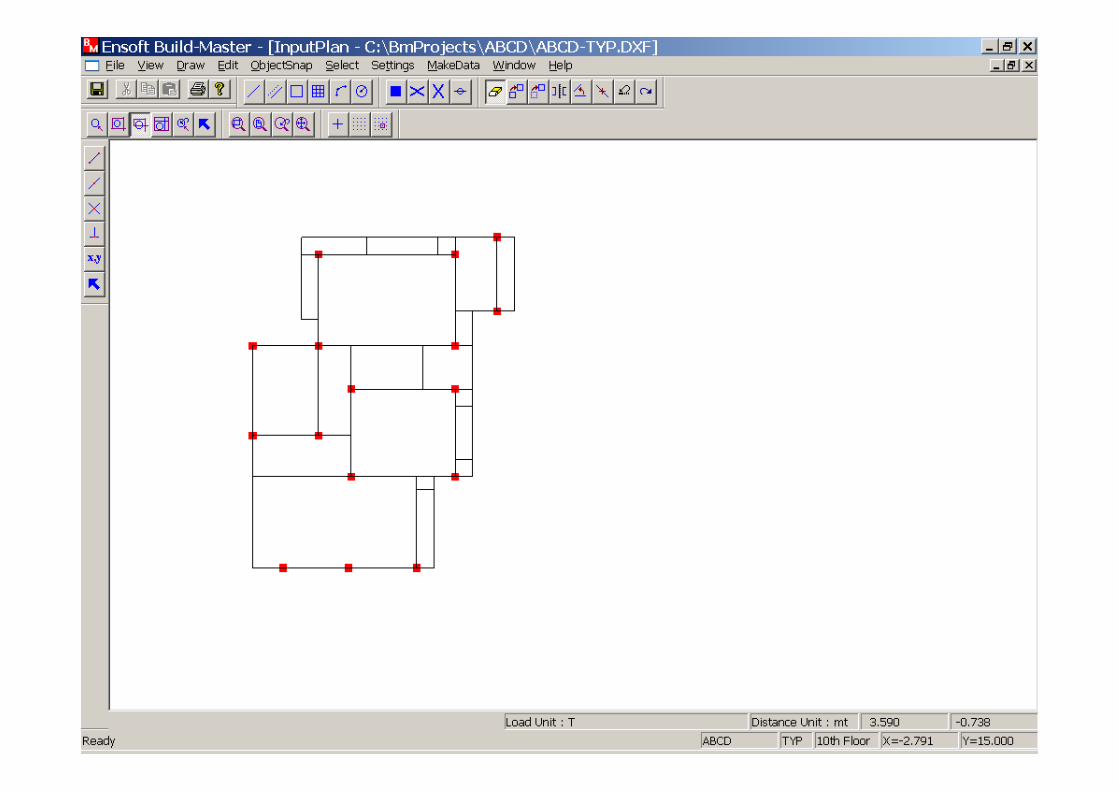
Now the floor plan is a line sketch with beam positions according to the Architectural drawing.
Now the floor plan is a line sketch with beam positions according to the Architectural drawing.

Select Support->Column option from the Draw menu to place the columns.
Select Support->Column option from the Draw menu to place the columns.

Select points for placement of columns by moving the pick box.
Select points for placement of columns by moving the pick box.
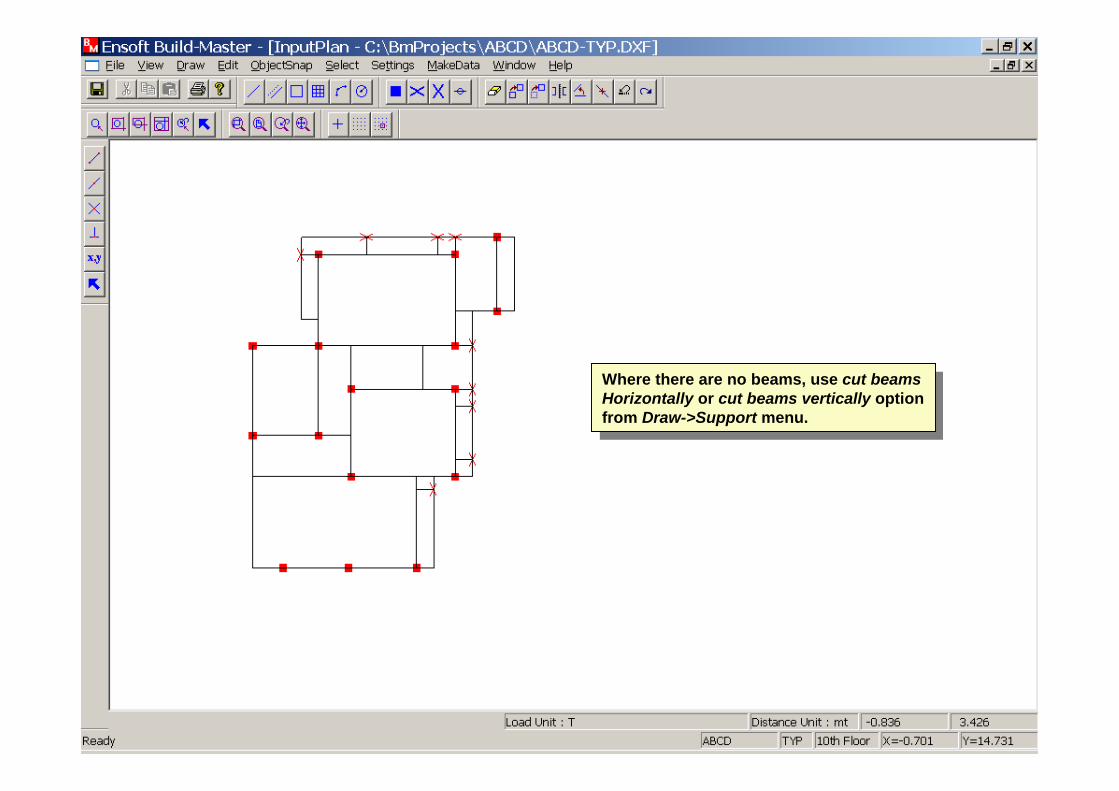
Where there are no beams, use cut beams Horizontally or cut beams vertically option from Draw->Support menu.
Where there are no beams, use cut beams Horizontally or cut beams vertically option from Draw->Support menu.
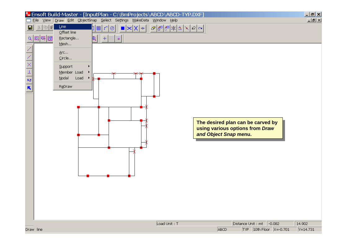
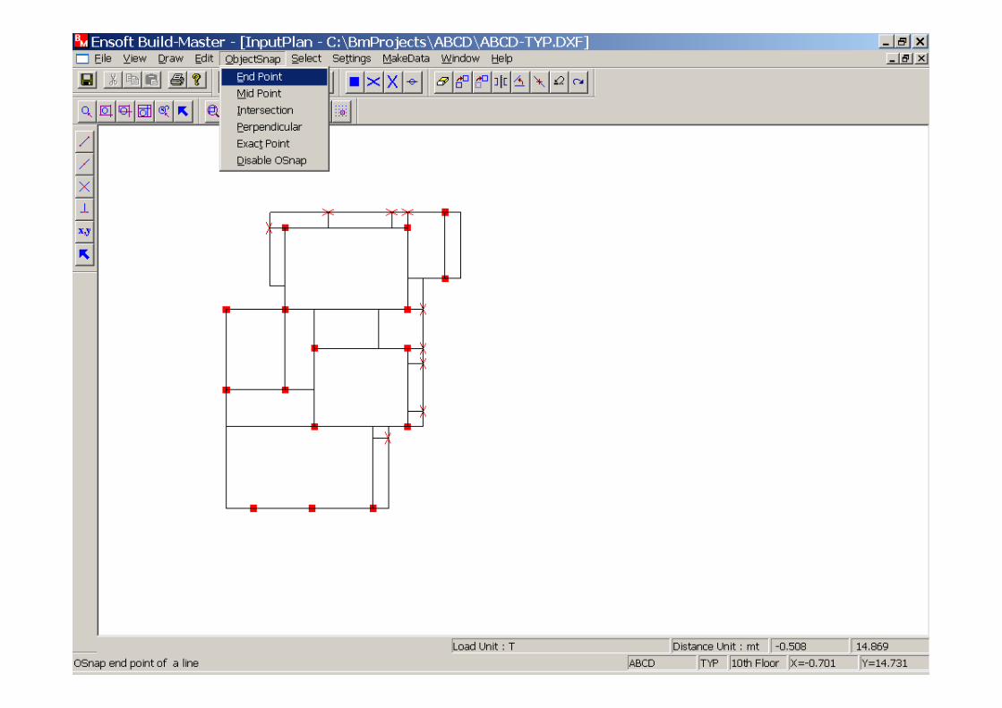
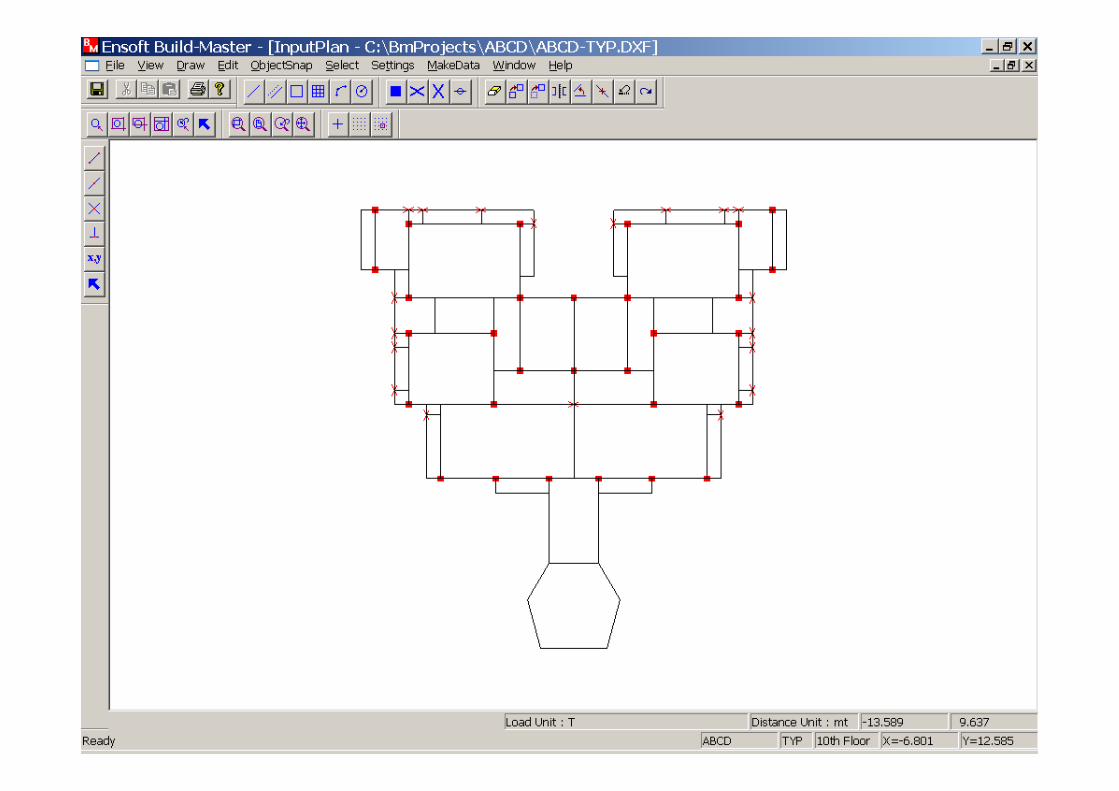
The desired plan can be carved by using various options from Draw and Object Snap menu.
The desired plan can be carved by using various options from Draw and Object Snap menu.

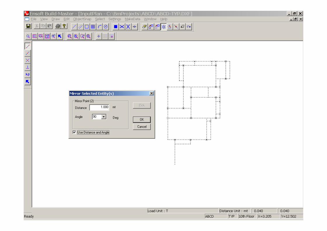
Now use Mirror option from the Edit menu to draw the mirror image of the entire plan.
Now use Mirror option from the Edit menu to draw the mirror image of the entire plan.

Now select the points at which mirror image is to be drawn.
Now select the points at which mirror image is to be drawn.
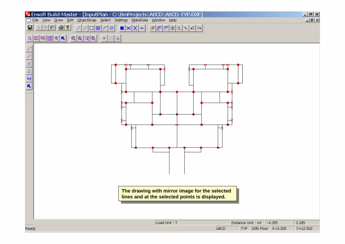
The drawing with mirror image for the selected lines and at the selected points is displayed.
The drawing with mirror image for the selected lines and at the selected points is displayed.
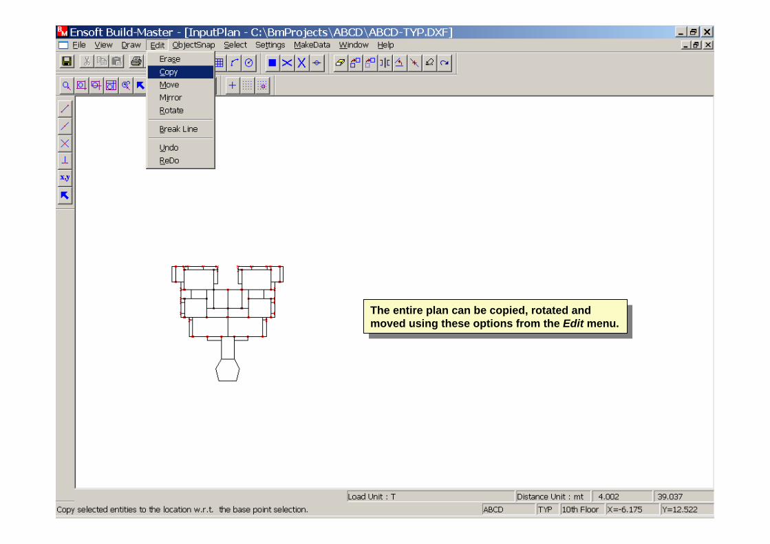
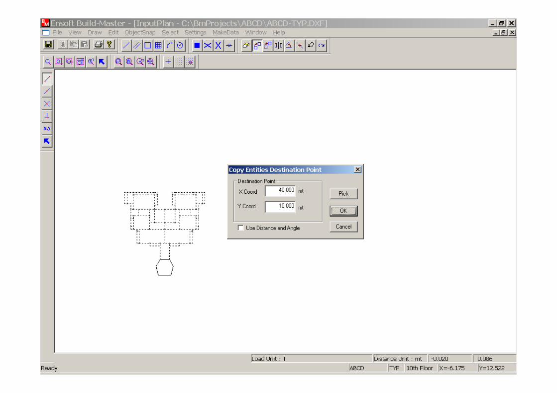
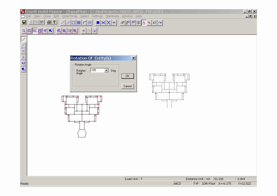
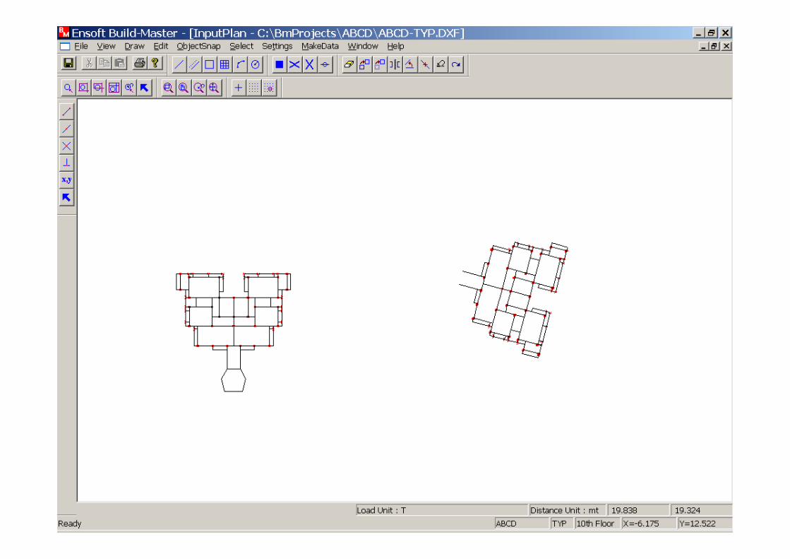
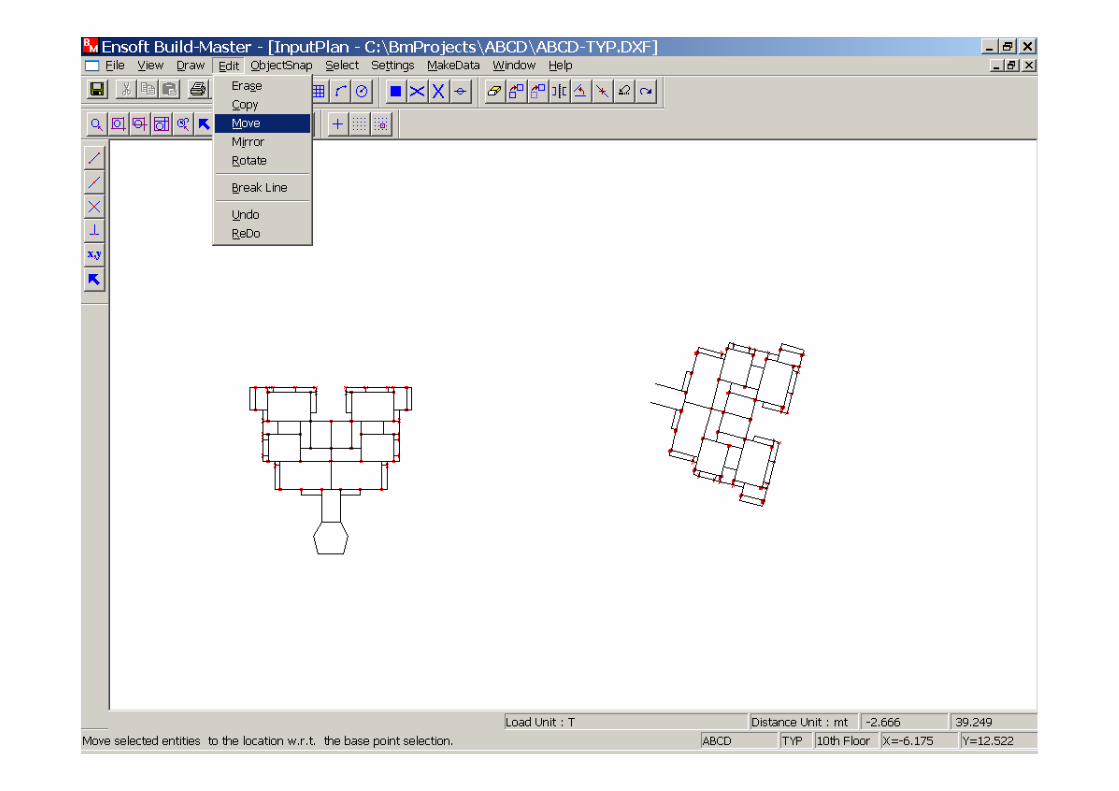
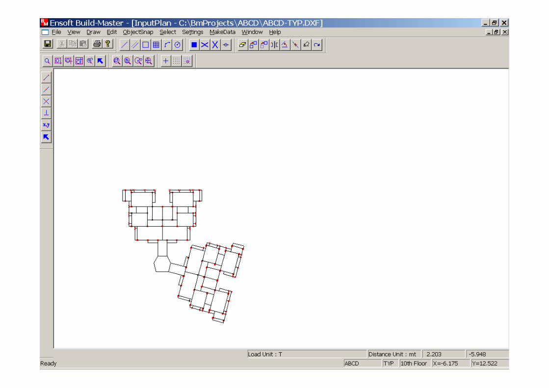
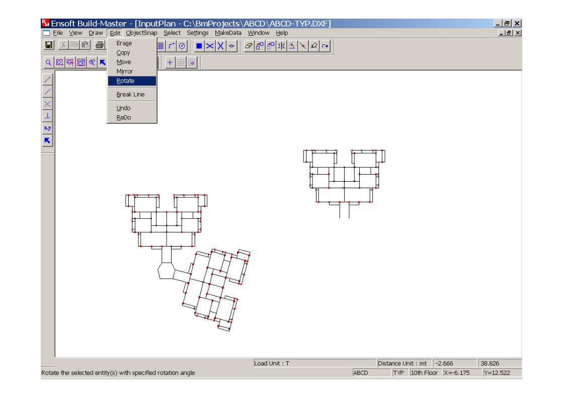
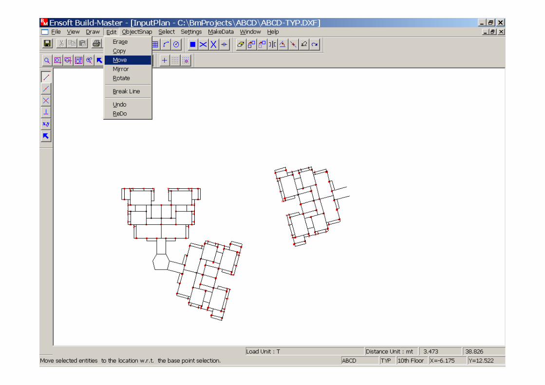
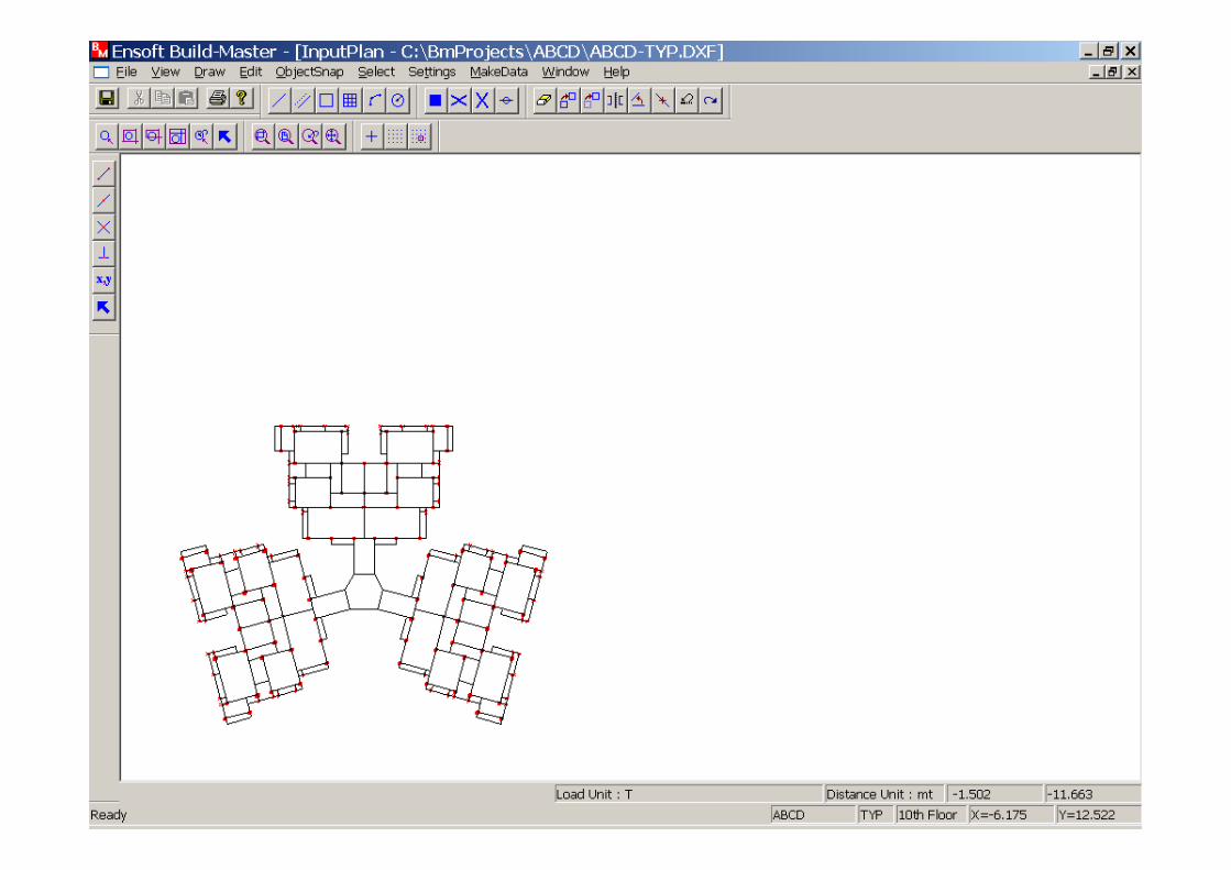
The entire plan can be copied, rotated and moved using these options from the Edit menu.
The entire plan can be copied, rotated and moved using these options from the Edit menu.


Shear Wall Idealization(Wide Column Analogy)
C4 B5 BF C5 BF B6 C6
C4 B5 BF C5 BF B6 C6
Shear Wall
A shear wall can be idealized in Build-master with Column Analogy method.A shear wall can be idealized in Build-master with Column Analogy method.
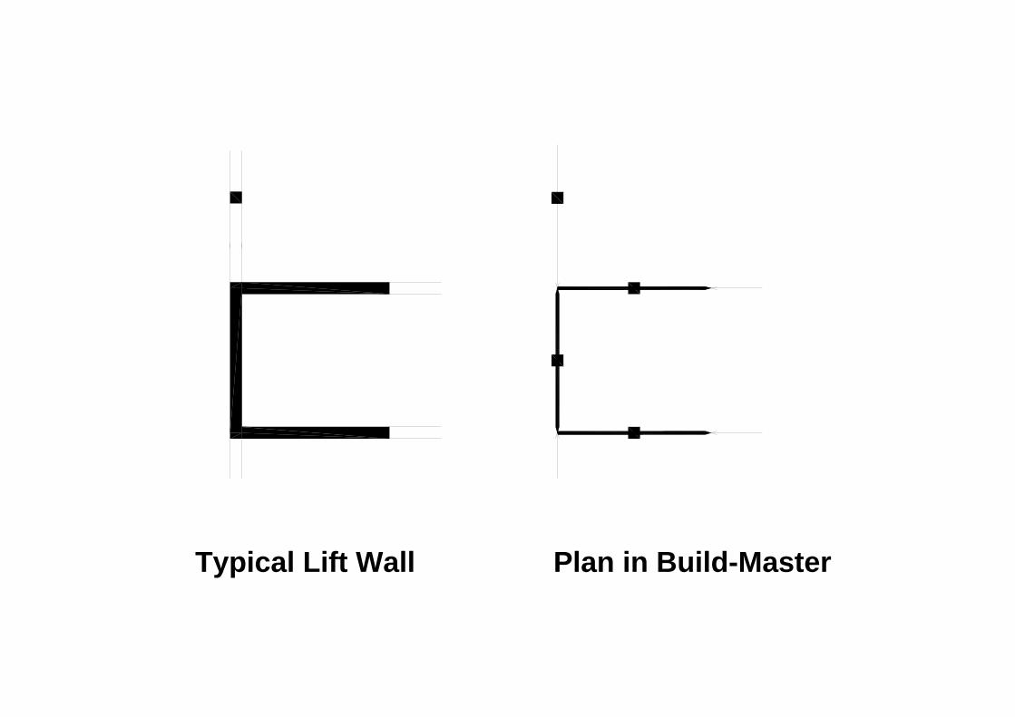
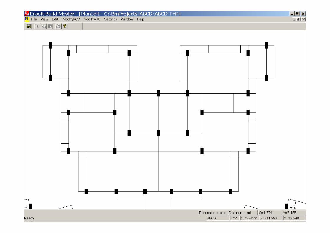
Typical Lift Wall Plan in Build-Master
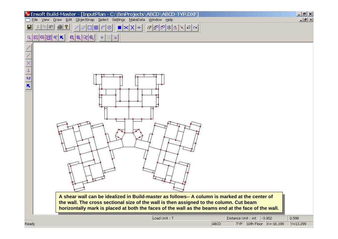
A shear wall can be idealized in Build-master as follows-- A column is marked at the center of the wall. The cross sectional size of the wall is then assigned to the column. Cut beam horizontally mark is placed at both the faces of the wall as the beams end at the face of the wall.
A shear wall can be idealized in Build-master as follows-- A column is marked at the center of the wall. The cross sectional size of the wall is then assigned to the column. Cut beam horizontally mark is placed at both the faces of the wall as the beams end at the face of the wall.
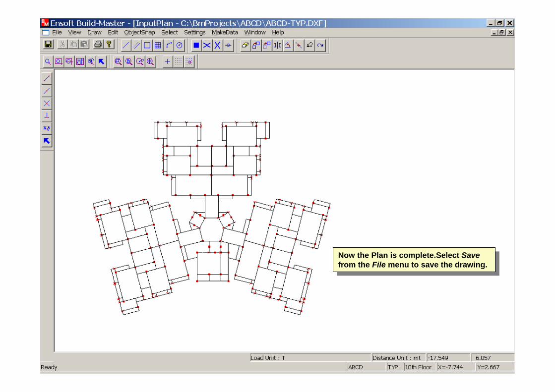
Now the Plan is complete.Select Save from the File menu to save the drawing.
Now the Plan is complete.Select Save from the File menu to save the drawing.
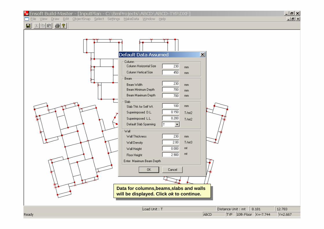
Data for columns,beams,slabs and walls will be displayed. Click ok to continue.
Data for columns,beams,slabs and walls will be displayed. Click ok to continue.
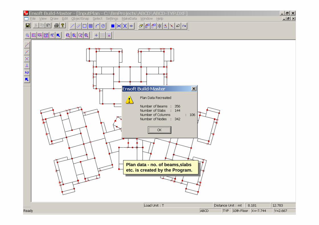
Plan data - no. of beams,slabs etc. is created by the Program.
Plan data - no. of beams,slabs etc. is created by the Program.


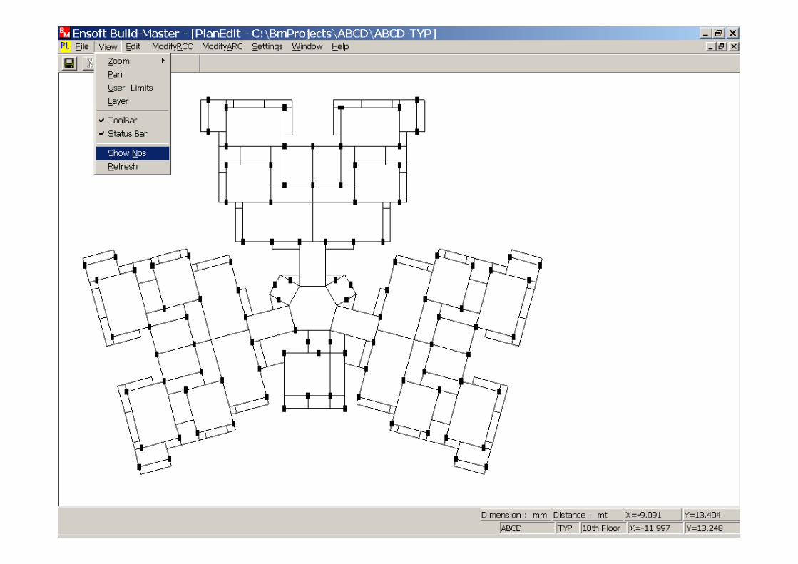
Now select Edit Plan Data from the Floor menu.Now select Edit Plan Data from the Floor menu.

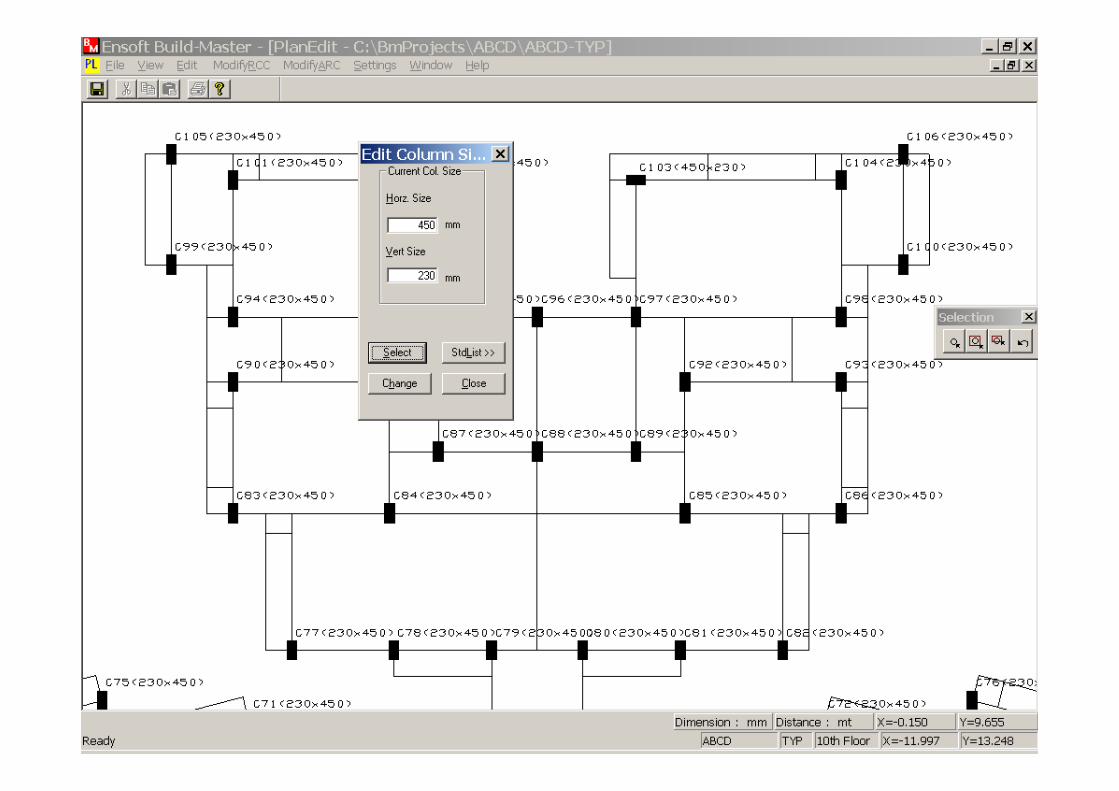
Now Select Column Data-->Column Size from the Edit menu.
Now Select Column Data-->Column Size from the Edit menu.
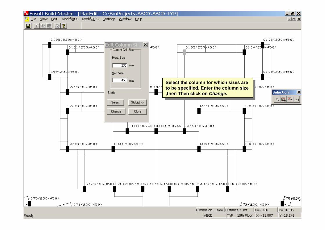
Select the column for which sizes are to be specified. Enter the column size ,then Then click on Change.
Select the column for which sizes are to be specified. Enter the column size ,then Then click on Change.
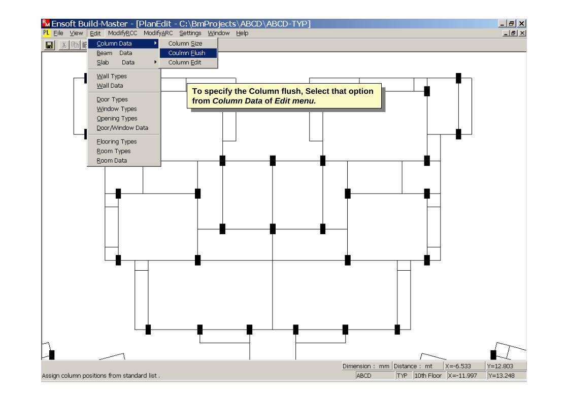
To specify the Column flush, Select that option from Column Data of Edit menu.
To specify the Column flush, Select that option from Column Data of Edit menu.

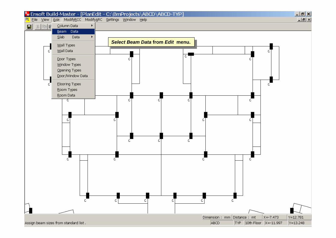
Select Beam Data from Edit menu.Select Beam Data from Edit menu.
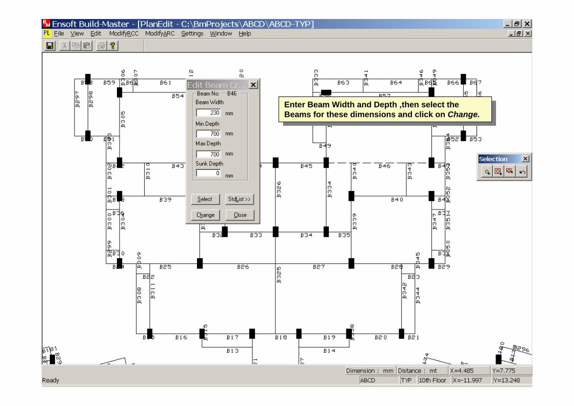
Enter Beam Width and Depth ,then select the Beams for these dimensions and click on Change.
Enter Beam Width and Depth ,then select the Beams for these dimensions and click on Change.

Now select Slab Data from the Edit menu. Select the option Spanning.
Now select Slab Data from the Edit menu. Select the option Spanning.
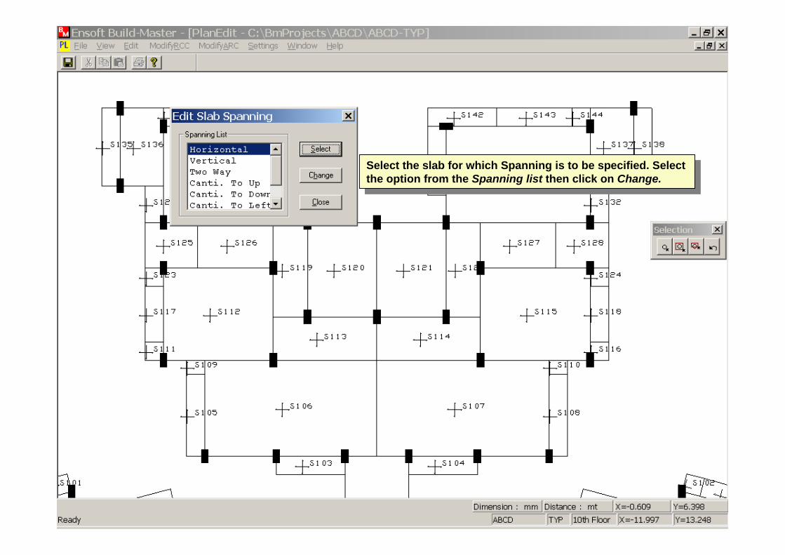
Select the slab for which Spanning is to be specified. Select the option from the Spanning list then click on Change.
Select the slab for which Spanning is to be specified. Select the option from the Spanning list then click on Change.

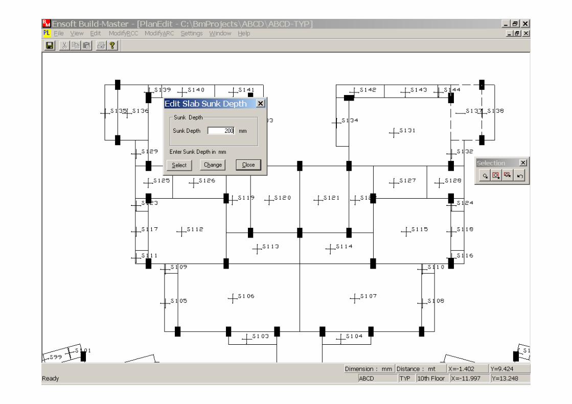
Now select Sunk Slab option from the Slab Data.Now select Sunk Slab option from the Slab Data.


Now select Wall Types from the Edit menu.Now select Wall Types from the Edit menu.
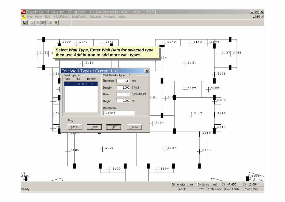
Select Wall Type, Enter Wall Data for selected type then use Add button to add more wall types.
Select Wall Type, Enter Wall Data for selected type then use Add button to add more wall types.

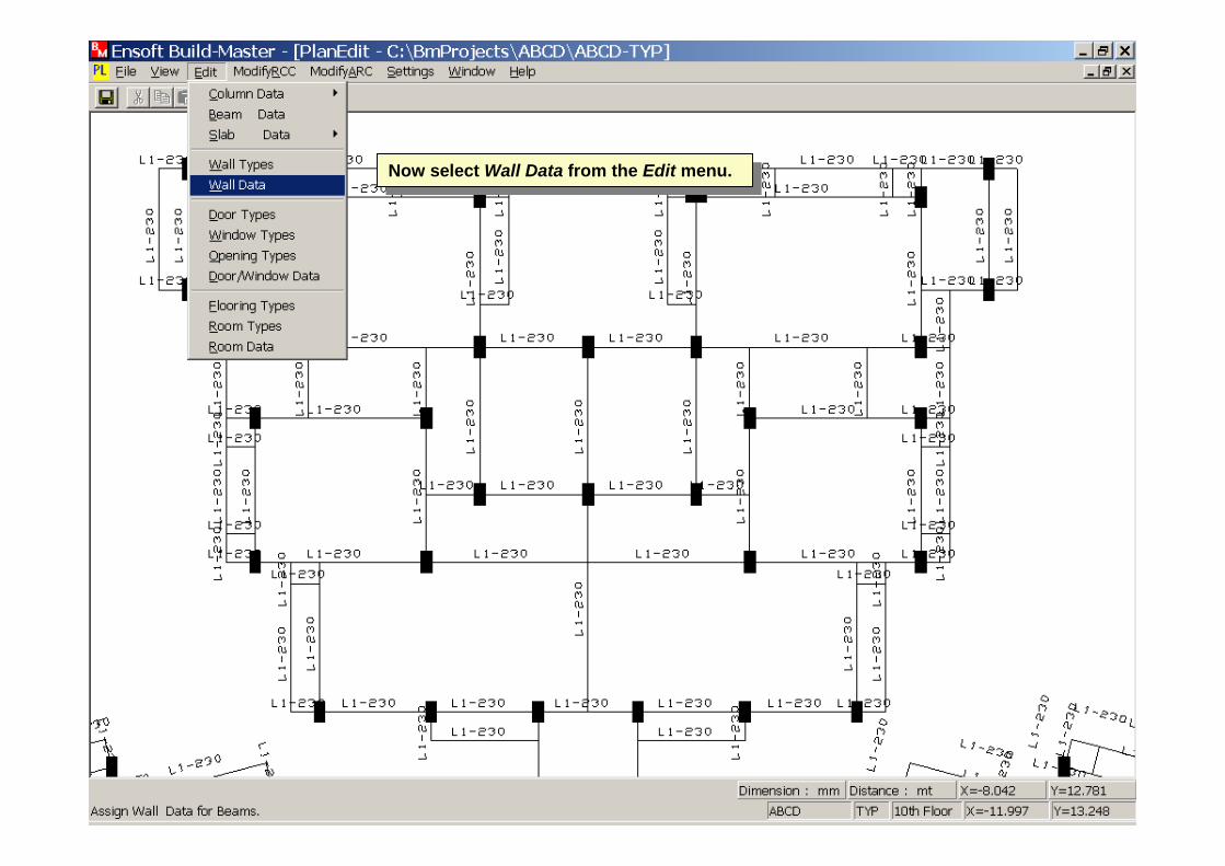
Now select Wall Data from the Edit menu.Now select Wall Data from the Edit menu.
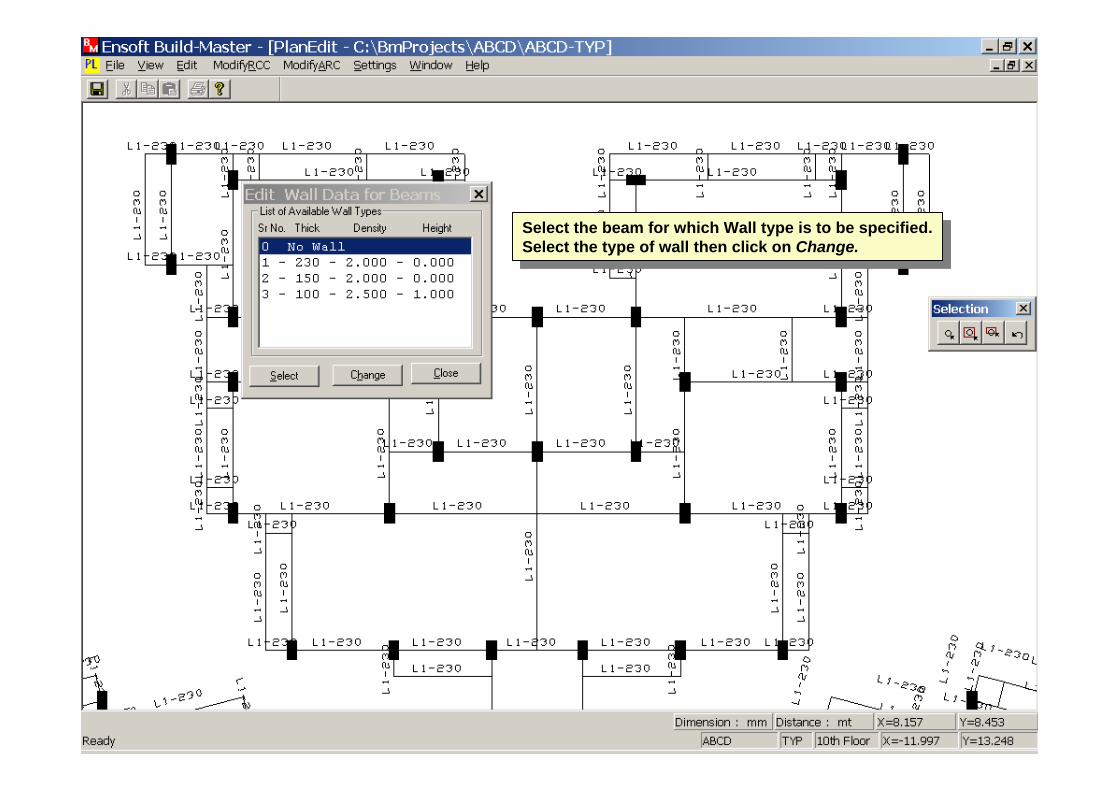
Select the beam for which Wall type is to be specified. Select the type of wall then click on Change.
Select the beam for which Wall type is to be specified. Select the type of wall then click on Change.

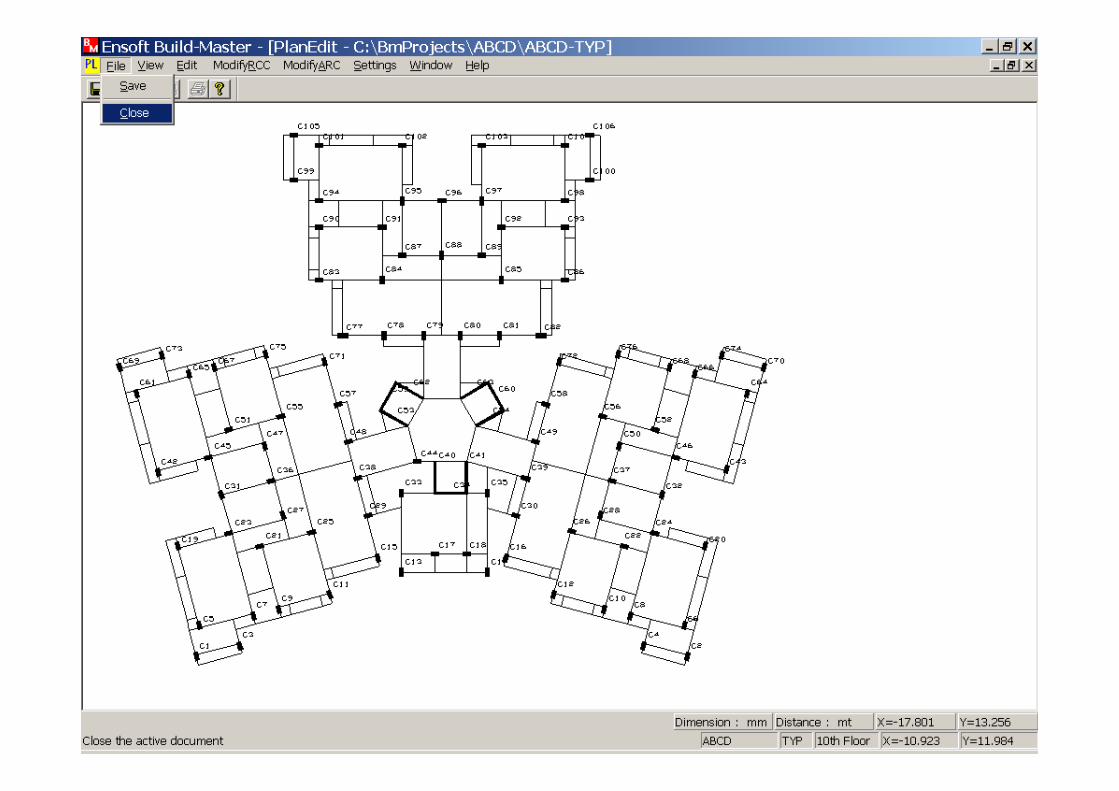
This completes the editing of Plan Data, hence Save the file and then Close.
This completes the editing of Plan Data, hence Save the file and then Close.
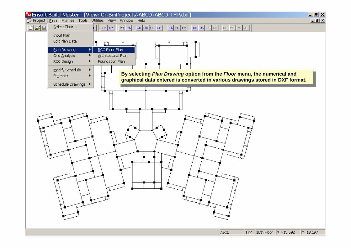
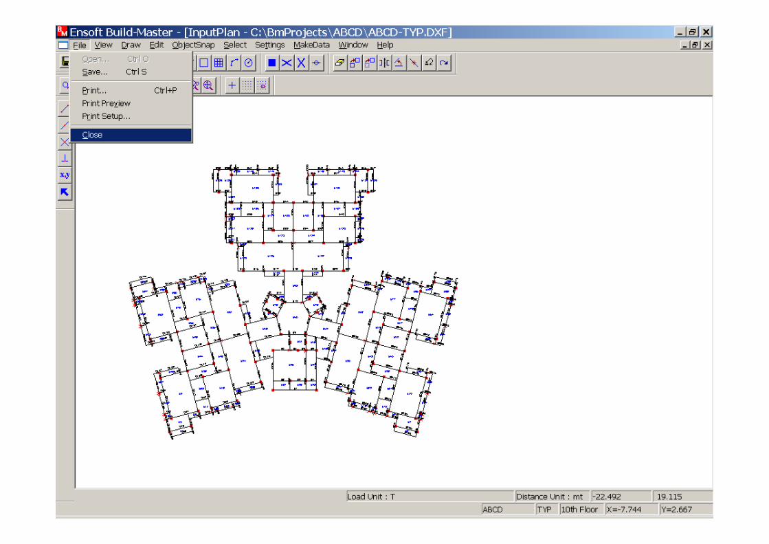
By selecting Plan Drawing option from the Floor menu, the numerical and graphical data entered is converted in various drawings stored in DXF format.
By selecting Plan Drawing option from the Floor menu, the numerical and graphical data entered is converted in various drawings stored in DXF format.
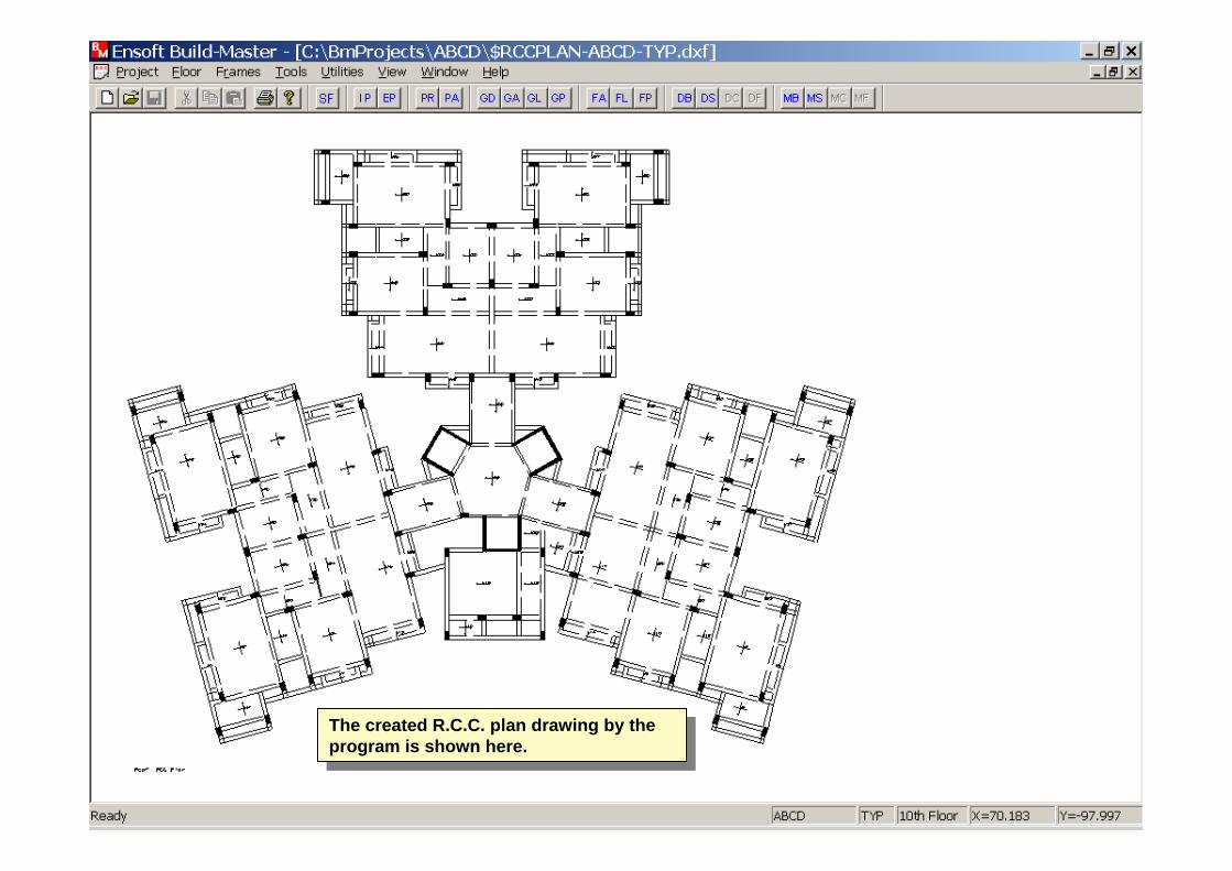
The created R.C.C. plan drawing by the program is shown here.
The created R.C.C. plan drawing by the program is shown here.

Select Architectural Plan from the Plan Drawing option of the Floor menu to view Architectural drawing.
Select Architectural Plan from the Plan Drawing option of the Floor menu to view Architectural drawing.

The Architectural drawing created is shown hereThe Architectural drawing created is shown here
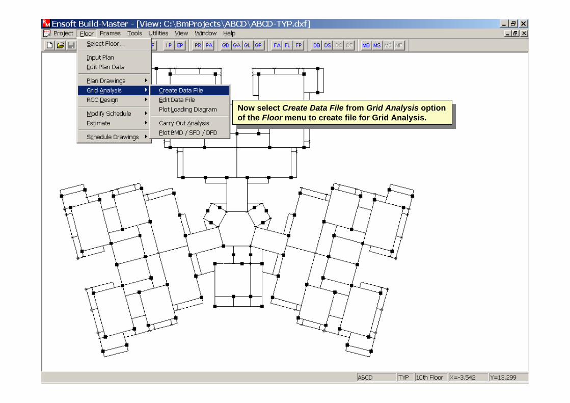
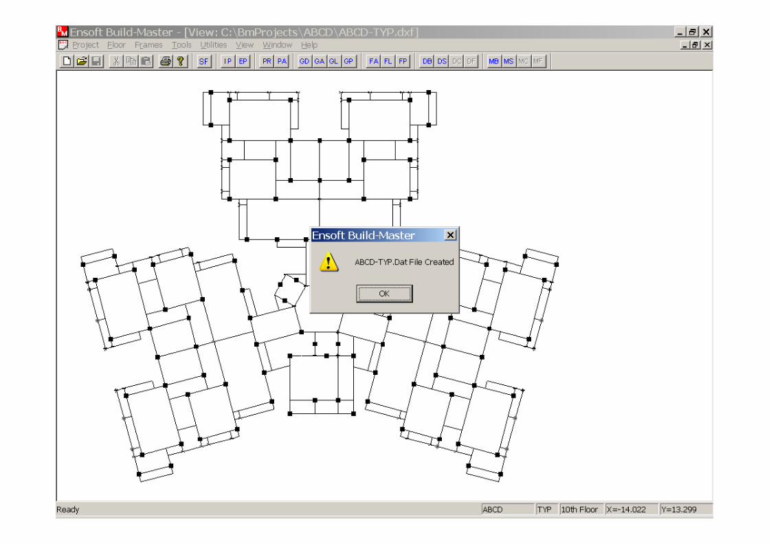
Now select Create Data File from Grid Analysis option of the Floor menu to create file for Grid Analysis.
Now select Create Data File from Grid Analysis option of the Floor menu to create file for Grid Analysis.
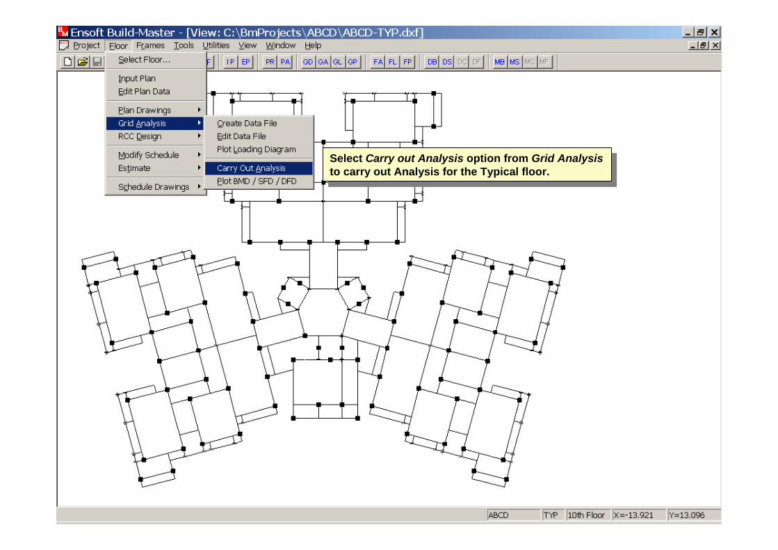
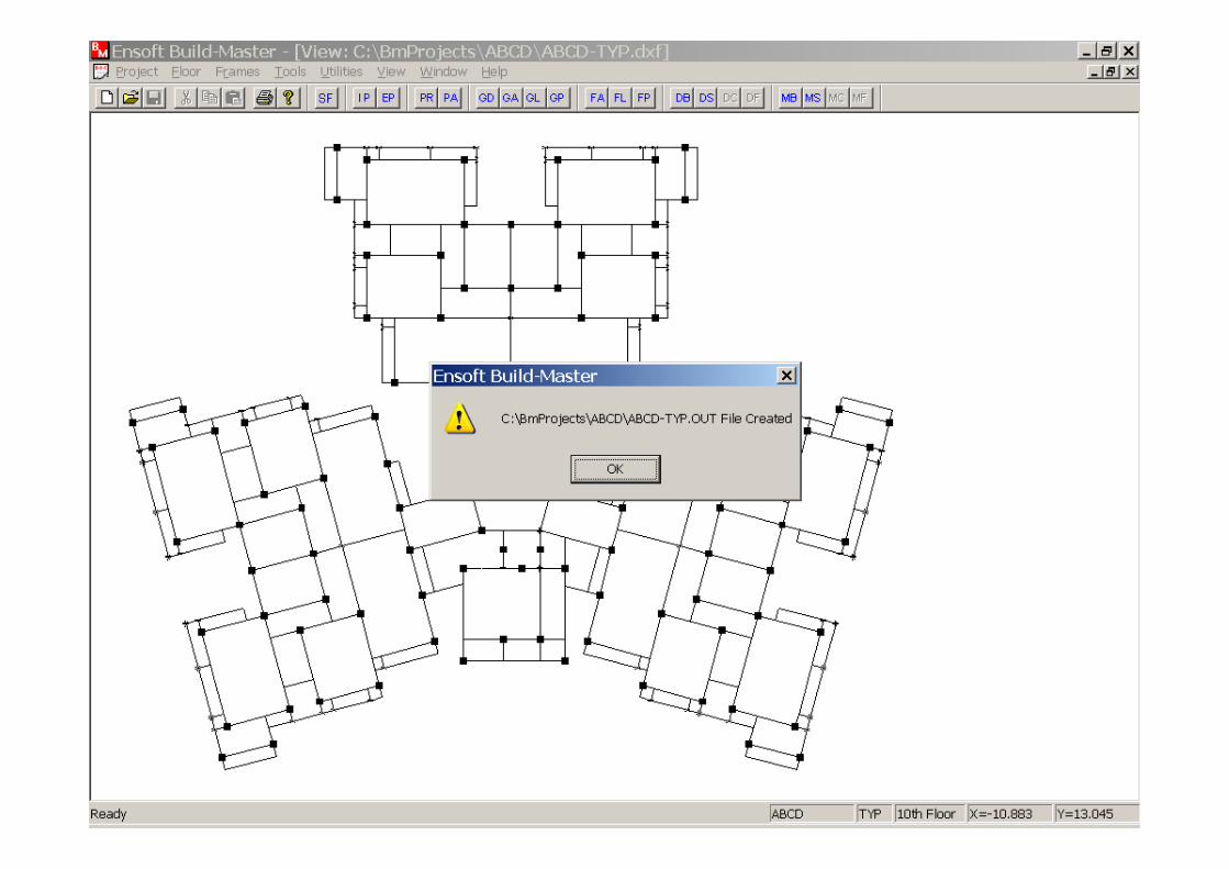
Select Carry out Analysis option from Grid Analysis to carry out Analysis for the Typical floor.
Select Carry out Analysis option from Grid Analysis to carry out Analysis for the Typical floor.
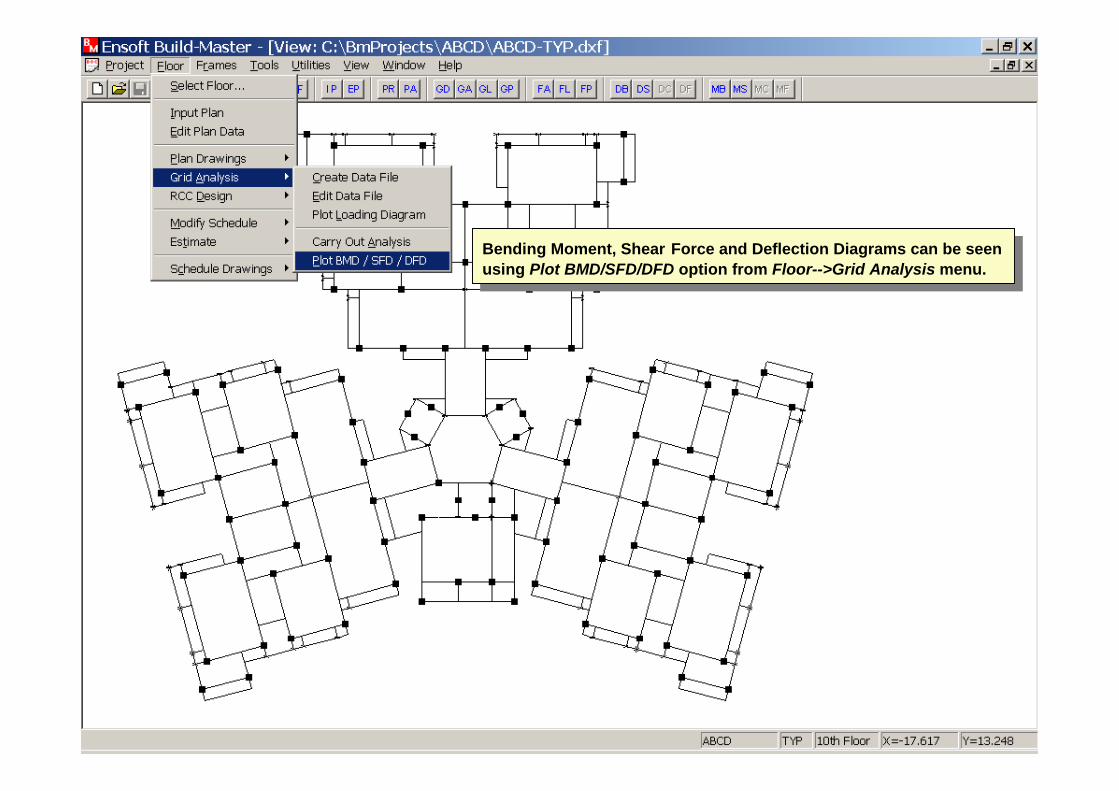
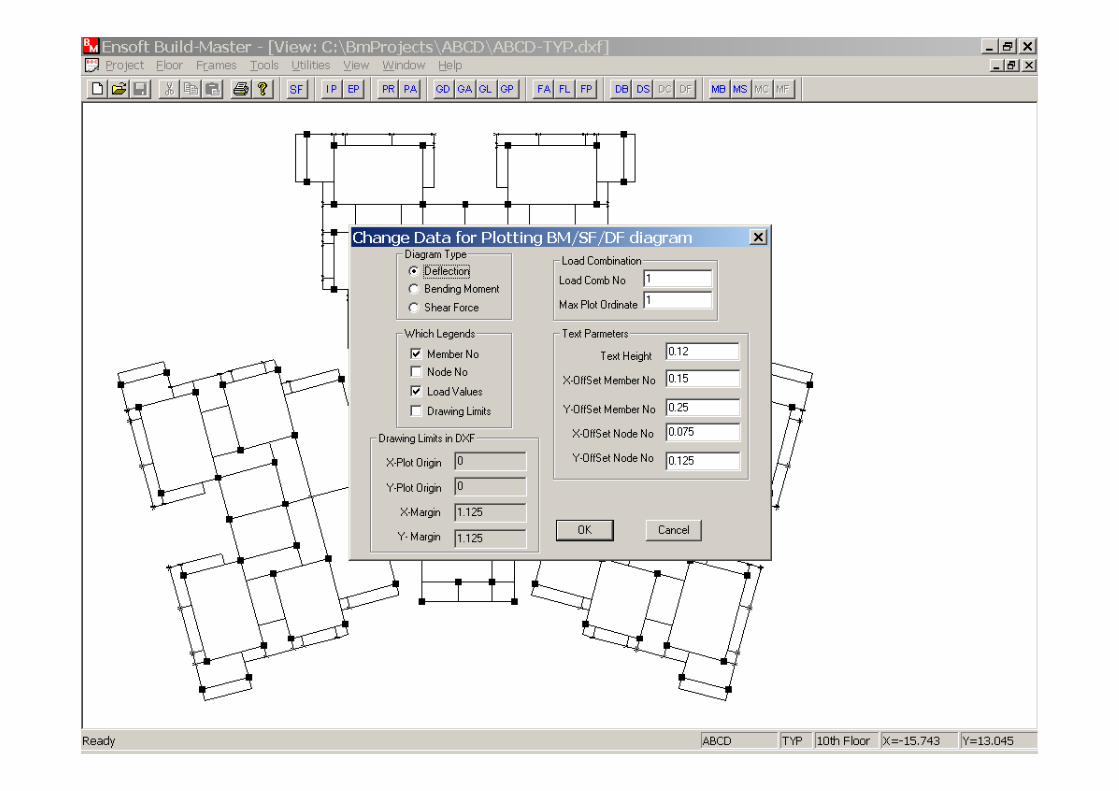
Bending Moment, Shear Force and Deflection Diagrams can be seen using Plot BMD/SFD/DFD option from Floor-->Grid Analysis menu.
Bending Moment, Shear Force and Deflection Diagrams can be seen using Plot BMD/SFD/DFD option from Floor-->Grid Analysis menu.
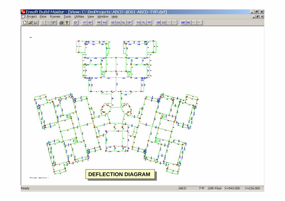
DEFLECTION DIAGRAMDEFLECTION DIAGRAM
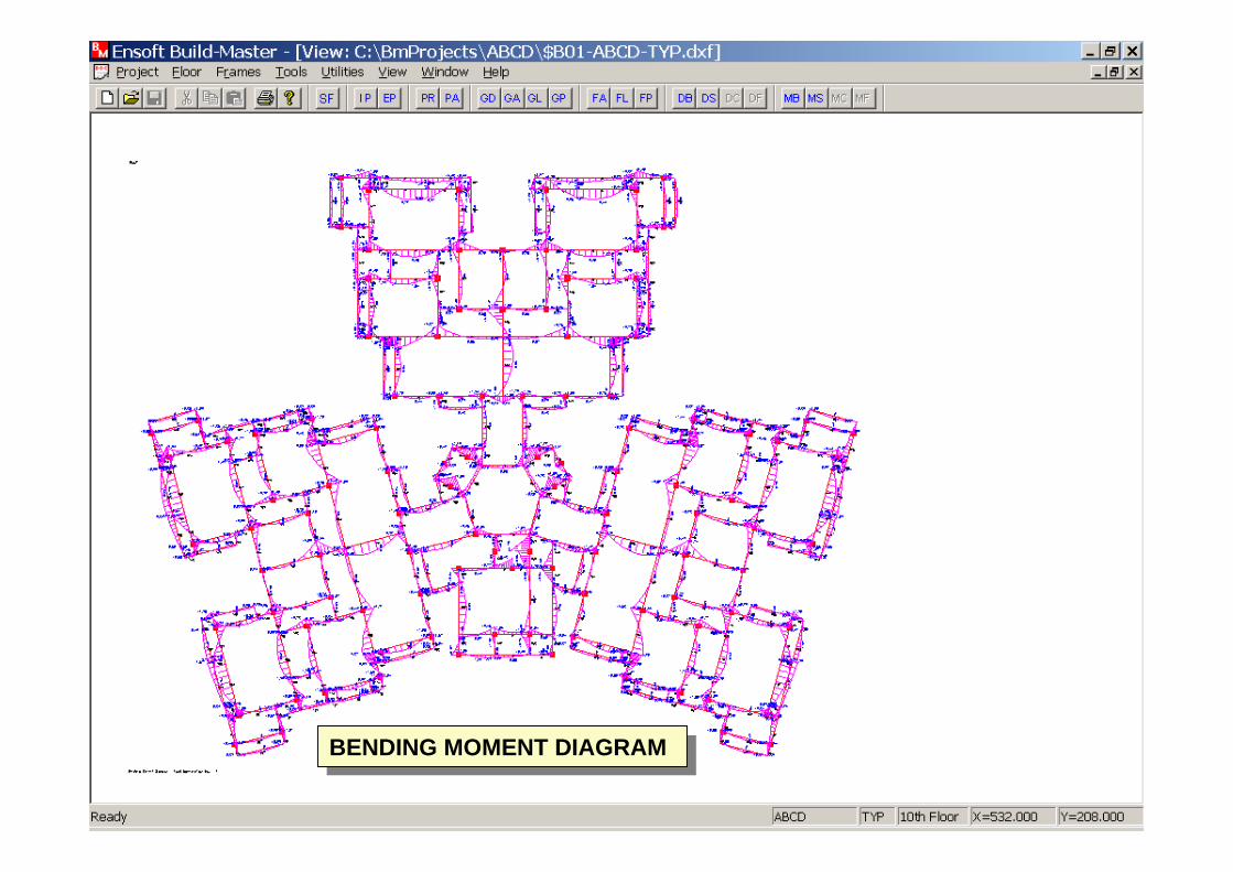
BENDING MOMENT DIAGRAMBENDING MOMENT DIAGRAM
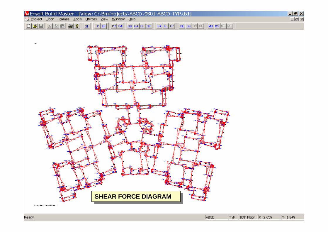
SHEAR FORCE DIAGRAMSHEAR FORCE DIAGRAM

Now copy plan for the Typical floor using Copy Floor option from the Utilities menu.
Now copy plan for the Typical floor using Copy Floor option from the Utilities menu.
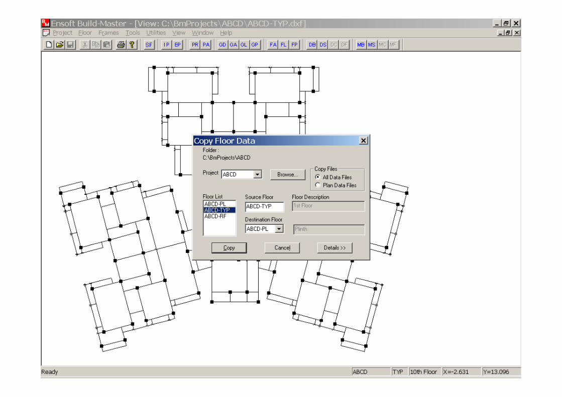
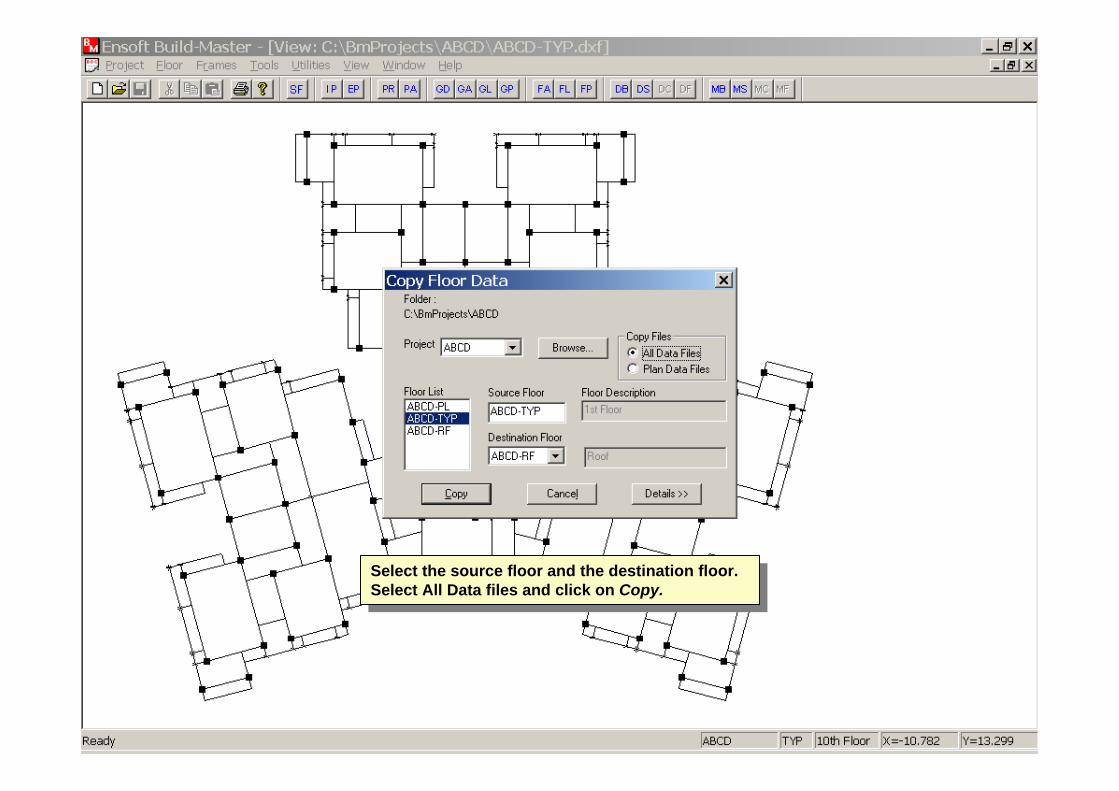
Select the source floor and the destination floor. Select All Data files and click on Copy.
Select the source floor and the destination floor. Select All Data files and click on Copy.
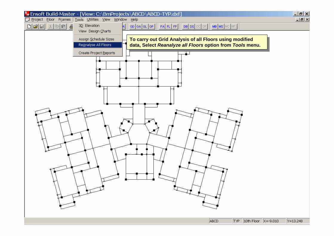
To carry out Grid Analysis of all Floors using modified data, Select Reanalyze all Floors option from Tools menu.
To carry out Grid Analysis of all Floors using modified data, Select Reanalyze all Floors option from Tools menu.
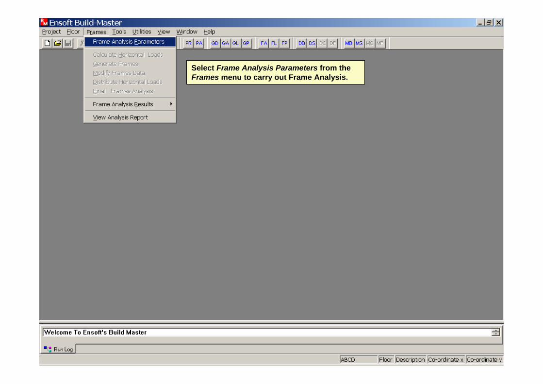
Select Frame Analysis Parameters from the Frames menu to carry out Frame Analysis.
Select Frame Analysis Parameters from the Frames menu to carry out Frame Analysis.
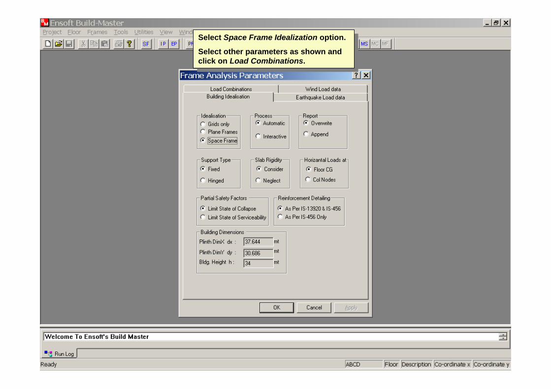
Select Space Frame Idealization option.
Select other parameters as shown and click on Load Combinations.
Select Space Frame Idealization option.
Select other parameters as shown and click on Load Combinations.
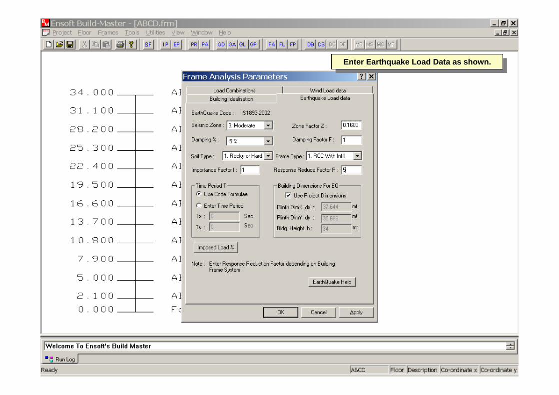
Enter Earthquake Load Data as shown.Enter Earthquake Load Data as shown.
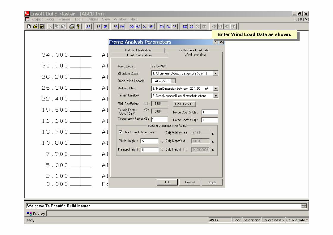
Enter Wind Load Data as shown.Enter Wind Load Data as shown.

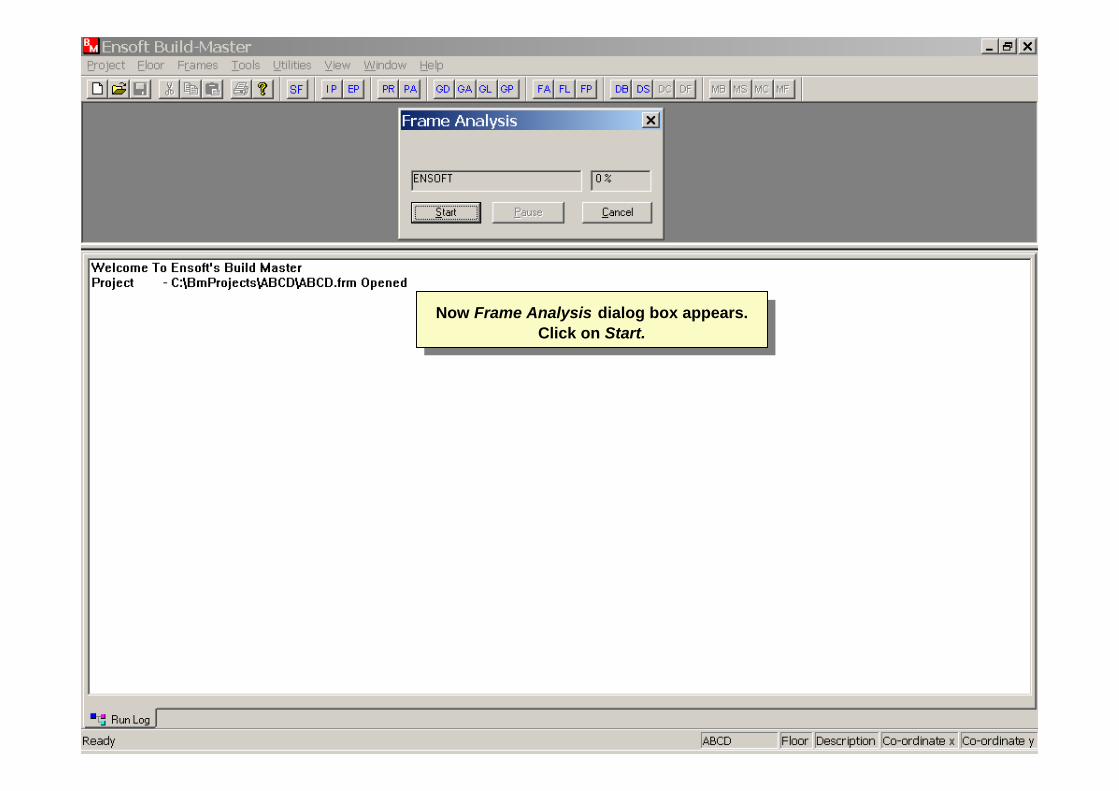
Now Frame Analysis dialog box appears. Click on Start.
Now Frame Analysis dialog box appears. Click on Start.
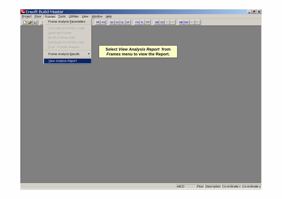
Select View Analysis Report from Frames menu to view the Report.
Select View Analysis Report from Frames menu to view the Report.
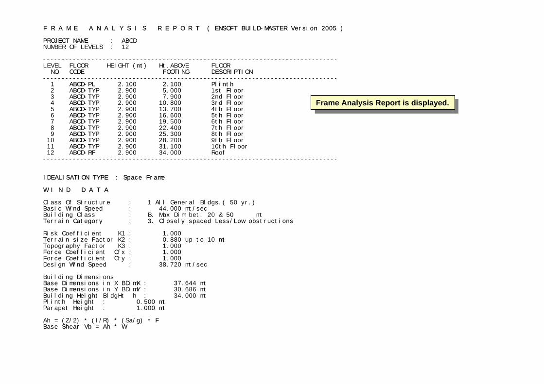
F R A M E A N A L Y S I S R E P O R T ( ENSOFT BUILD-MASTER Version 2005 ) PROJECT NAME : ABCD NUMBER OF LEVELS : 12 ------------------------------------------------------------------------------- LEVEL FLOOR HEIGHT (mt) Ht.ABOVE FLOOR NO. CODE FOOTING DESCRIPTION ------------------------------------------------------------------------------- 1 ABCD-PL 2.100 2.100 Plinth 2 ABCD-TYP 2.900 5.000 1st Floor 3 ABCD-TYP 2.900 7.900 2nd Floor 4 ABCD-TYP 2.900 10.800 3rd Floor 5 ABCD-TYP 2.900 13.700 4th Floor 6 ABCD-TYP 2.900 16.600 5th Floor 7 ABCD-TYP 2.900 19.500 6th Floor 8 ABCD-TYP 2.900 22.400 7th Floor 9 ABCD-TYP 2.900 25.300 8th Floor 10 ABCD-TYP 2.900 28.200 9th Floor 11 ABCD-TYP 2.900 31.100 10th Floor 12 ABCD-RF 2.900 34.000 Roof ------------------------------------------------------------------------------- IDEALISATION TYPE : Space Frame W I N D D A T A Class Of Structure : 1 All General Bldgs.( 50 yr.) Basic Wind Speed : 44.000 mt/sec Building Class : B. Max Dim bet. 20 & 50 mt Terrain Category : 3. Closely spaced Less/Low obstructions Risk Coefficient K1 : 1.000 Terrain size Factor K2 : 0.880 up to 10 mt Topography Factor K3 : 1.000 Force Coefficient Cfx : 1.000 Force Coefficient Cfy : 1.000 Design Wind Speed : 38.720 mt/sec Building Dimensions Base Dimensions in X BDimX : 37.644 mt Base Dimensions in Y BDimY : 30.686 mt Building Height BldgHt h : 34.000 mt Plinth Height : 0.500 mt Parapet Height : 1.000 mt Ah = (Z/2) * (I/R) * (Sa/g) * F Base Shear Vb = Ah * W
Frame Analysis Report is displayed.Frame Analysis Report is displayed.
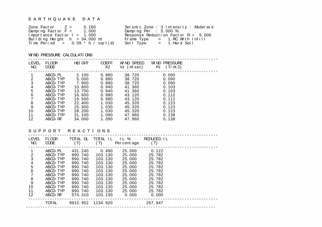
E A R T H Q U A K E D A T A Zone Factor Z = 0.160 Seismic Zone : 3 Intensity : Moderate Damping Factor F = 1.000 Damping Per : 5.000 % Importance Factor I = 1.000 Response Reduction Factor R = 5.000 Building Height h = 34.000 mt Frame Type = 1.RC With Infill Time Period = 0.09 * h / sqrt(d) Soil Type = 1.Hard Soil WIND PRESSURE CALCULATIONS ------------------------------------------------------------------------------- LEVEL FLOOR HEIGHT COEFF WIND SPEED WIND PRESSURE NO. CODE K2 Vz (m/sec) Pz (T/mt2) ------------------------------------------------------------------------------- 1 ABCD-PL 2.100 0.880 38.720 0.090 2 ABCD-TYP 5.000 0.880 38.720 0.090 3 ABCD-TYP 7.900 0.880 38.720 0.090 4 ABCD-TYP 10.800 0.940 41.360 0.103 5 ABCD-TYP 13.700 0.940 41.360 0.103 6 ABCD-TYP 16.600 0.980 43.120 0.112 7 ABCD-TYP 19.500 0.980 43.120 0.112 8 ABCD-TYP 22.400 1.030 45.320 0.123 9 ABCD-TYP 25.300 1.030 45.320 0.123 10 ABCD-TYP 28.200 1.030 45.320 0.123 11 ABCD-TYP 31.100 1.090 47.960 0.138 12 ABCD-RF 34.000 1.090 47.960 0.138 S U P P O R T R E A C T I O N S ------------------------------------------------------------------------------- LEVEL FLOOR TOTAL DL TOTAL IL IL % REDUCED IL NO. CODE (T) (T) Percentage (T) ------------------------------------------------------------------------------- 1 ABCD-PL 431.240 0.490 25.000 0.122 2 ABCD-TYP 890.740 103.130 25.000 25.782 3 ABCD-TYP 890.740 103.130 25.000 25.782 4 ABCD-TYP 890.740 103.130 25.000 25.782 5 ABCD-TYP 890.740 103.130 25.000 25.782 6 ABCD-TYP 890.740 103.130 25.000 25.782 7 ABCD-TYP 890.740 103.130 25.000 25.782 8 ABCD-TYP 890.740 103.130 25.000 25.782 9 ABCD-TYP 890.740 103.130 25.000 25.782 10 ABCD-TYP 890.740 103.130 25.000 25.782 11 ABCD-TYP 890.740 103.130 25.000 25.782 12 ABCD-RF 574.310 103.130 0.000 0.000 ------------------------------------------------------------------------------- TOTAL 9912.952 1134.920 257.947 -------------------------------------------------------------------------------
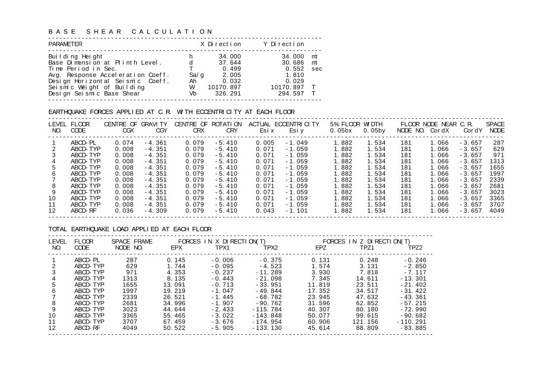
B A S E S H E A R C A L C U L A T I O N -------------------------------------------------------------------------- PARAMETER X Direction Y Direction -------------------------------------------------------------------------- Building Height h 34.000 34.000 mt Base Dimension at Plinth Level. d 37.644 30.686 mt Time Period in Sec. T 0.499 0.552 sec Avg. Response Acceleration Coeff. Sa/g 2.005 1.810 Design Horizontal Seismic Coeff. Ah 0.032 0.029 Seismic Weight of Building W 10170.897 10170.897 T Design Seismic Base Shear Vb 326.291 294.597 T -------------------------------------------------------------------------- EARTHQUAKE FORCES APPLIED AT C.R. WITH ECCENTRICITY AT EACH FLOOR --------------------------------------------------------------------------------------------------------------------------- LEVEL FLOOR CENTRE OF GRAVITY CENTRE OF ROTATION ACTUAL ECCENTRICITY 5% FLOOR WIDTH FLOOR NODE NEAR C.R. SPACE NO. CODE CGX CGY CRX CRY Esix Esiy 0.05bx 0.05by NODE NO. CordX CordY NODE --------------------------------------------------------------------------------------------------------------------------- 1 ABCD-PL 0.074 -4.361 0.079 -5.410 0.005 -1.049 1.882 1.534 181 1.066 -3.657 287 2 ABCD-TYP 0.008 -4.351 0.079 -5.410 0.071 -1.059 1.882 1.534 181 1.066 -3.657 629 3 ABCD-TYP 0.008 -4.351 0.079 -5.410 0.071 -1.059 1.882 1.534 181 1.066 -3.657 971 4 ABCD-TYP 0.008 -4.351 0.079 -5.410 0.071 -1.059 1.882 1.534 181 1.066 -3.657 1313 5 ABCD-TYP 0.008 -4.351 0.079 -5.410 0.071 -1.059 1.882 1.534 181 1.066 -3.657 1655 6 ABCD-TYP 0.008 -4.351 0.079 -5.410 0.071 -1.059 1.882 1.534 181 1.066 -3.657 1997 7 ABCD-TYP 0.008 -4.351 0.079 -5.410 0.071 -1.059 1.882 1.534 181 1.066 -3.657 2339 8 ABCD-TYP 0.008 -4.351 0.079 -5.410 0.071 -1.059 1.882 1.534 181 1.066 -3.657 2681 9 ABCD-TYP 0.008 -4.351 0.079 -5.410 0.071 -1.059 1.882 1.534 181 1.066 -3.657 3023 10 ABCD-TYP 0.008 -4.351 0.079 -5.410 0.071 -1.059 1.882 1.534 181 1.066 -3.657 3365 11 ABCD-TYP 0.008 -4.351 0.079 -5.410 0.071 -1.059 1.882 1.534 181 1.066 -3.657 3707 12 ABCD-RF 0.036 -4.309 0.079 -5.410 0.043 -1.101 1.882 1.534 181 1.066 -3.657 4049 --------------------------------------------------------------------------------------------------------------------------- TOTAL EARTHQUAKE LOAD APPLIED AT EACH FLOOR -------------------------------------------------------------------------------------------------------- LEVEL FLOOR SPACE FRAME FORCES IN X DIRECTION(T) FORCES IN Z DIRECTION(T) NO. CODE NODE NO. EPX TPX1 TPX2 EPZ TPZ1 TPZ2 -------------------------------------------------------------------------------------------------------- 1 ABCD-PL 287 0.145 -0.006 -0.375 0.131 0.248 -0.246 2 ABCD-TYP 629 1.744 -0.095 -4.523 1.574 3.131 -2.850 3 ABCD-TYP 971 4.353 -0.237 -11.289 3.930 7.818 -7.117 4 ABCD-TYP 1313 8.135 -0.443 -21.098 7.345 14.611 -13.301 5 ABCD-TYP 1655 13.091 -0.713 -33.951 11.819 23.511 -21.402 6 ABCD-TYP 1997 19.219 -1.047 -49.844 17.352 34.517 -31.422 7 ABCD-TYP 2339 26.521 -1.445 -68.782 23.945 47.632 -43.361 8 ABCD-TYP 2681 34.996 -1.907 -90.762 31.596 62.852 -57.215 9 ABCD-TYP 3023 44.644 -2.433 -115.784 40.307 80.180 -72.990 10 ABCD-TYP 3365 55.465 -3.022 -143.848 50.077 99.615 -90.682 11 ABCD-TYP 3707 67.459 -3.676 -174.954 60.906 121.156 -110.291 12 ABCD-RF 4049 50.522 -5.905 -133.130 45.614 88.809 -83.885 --------------------------------------------------------------------------------------------------------
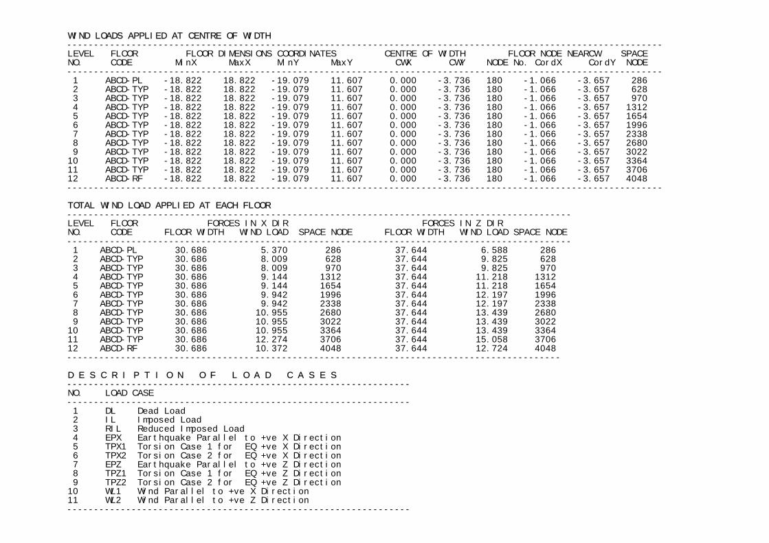
WIND LOADS APPLIED AT CENTRE OF WIDTH --------------------------------------------------------------------------------------------------------------- LEVEL FLOOR FLOOR DIMENSIONS COORDINATES CENTRE OF WIDTH FLOOR NODE NEARCW SPACE NO. CODE MinX MaxX MinY MaxY CWX CWY NODE No. CordX CordY NODE --------------------------------------------------------------------------------------------------------------- 1 ABCD-PL -18.822 18.822 -19.079 11.607 0.000 -3.736 180 -1.066 -3.657 286 2 ABCD-TYP -18.822 18.822 -19.079 11.607 0.000 -3.736 180 -1.066 -3.657 628 3 ABCD-TYP -18.822 18.822 -19.079 11.607 0.000 -3.736 180 -1.066 -3.657 970 4 ABCD-TYP -18.822 18.822 -19.079 11.607 0.000 -3.736 180 -1.066 -3.657 1312 5 ABCD-TYP -18.822 18.822 -19.079 11.607 0.000 -3.736 180 -1.066 -3.657 1654 6 ABCD-TYP -18.822 18.822 -19.079 11.607 0.000 -3.736 180 -1.066 -3.657 1996 7 ABCD-TYP -18.822 18.822 -19.079 11.607 0.000 -3.736 180 -1.066 -3.657 2338 8 ABCD-TYP -18.822 18.822 -19.079 11.607 0.000 -3.736 180 -1.066 -3.657 2680 9 ABCD-TYP -18.822 18.822 -19.079 11.607 0.000 -3.736 180 -1.066 -3.657 3022 10 ABCD-TYP -18.822 18.822 -19.079 11.607 0.000 -3.736 180 -1.066 -3.657 3364 11 ABCD-TYP -18.822 18.822 -19.079 11.607 0.000 -3.736 180 -1.066 -3.657 3706 12 ABCD-RF -18.822 18.822 -19.079 11.607 0.000 -3.736 180 -1.066 -3.657 4048 --------------------------------------------------------------------------------------------------------------- TOTAL WIND LOAD APPLIED AT EACH FLOOR ---------------------------------------------------------------------------------------------- LEVEL FLOOR FORCES IN X DIR FORCES IN Z DIR NO. CODE FLOOR WIDTH WIND LOAD SPACE NODE FLOOR WIDTH WIND LOAD SPACE NODE ---------------------------------------------------------------------------------------------- 1 ABCD-PL 30.686 5.370 286 37.644 6.588 286 2 ABCD-TYP 30.686 8.009 628 37.644 9.825 628 3 ABCD-TYP 30.686 8.009 970 37.644 9.825 970 4 ABCD-TYP 30.686 9.144 1312 37.644 11.218 1312 5 ABCD-TYP 30.686 9.144 1654 37.644 11.218 1654 6 ABCD-TYP 30.686 9.942 1996 37.644 12.197 1996 7 ABCD-TYP 30.686 9.942 2338 37.644 12.197 2338 8 ABCD-TYP 30.686 10.955 2680 37.644 13.439 2680 9 ABCD-TYP 30.686 10.955 3022 37.644 13.439 3022 10 ABCD-TYP 30.686 10.955 3364 37.644 13.439 3364 11 ABCD-TYP 30.686 12.274 3706 37.644 15.058 3706 12 ABCD-RF 30.686 10.372 4048 37.644 12.724 4048 -------------------------------------------------------------------------------------------- D E S C R I P T I O N O F L O A D C A S E S ---------------------------------------------------------------- NO. LOAD CASE ---------------------------------------------------------------- 1 DL Dead Load 2 IL Imposed Load 3 RIL Reduced Imposed Load 4 EPX Earthquake Parallel to +ve X Direction 5 TPX1 Torsion Case 1 for EQ +ve X Direction 6 TPX2 Torsion Case 2 for EQ +ve X Direction 7 EPZ Earthquake Parallel to +ve Z Direction 8 TPZ1 Torsion Case 1 for EQ +ve Z Direction 9 TPZ2 Torsion Case 2 for EQ +ve Z Direction 10 WL1 Wind Parallel to +ve X Direction 11 WL2 Wind Parallel to +ve Z Direction ----------------------------------------------------------------
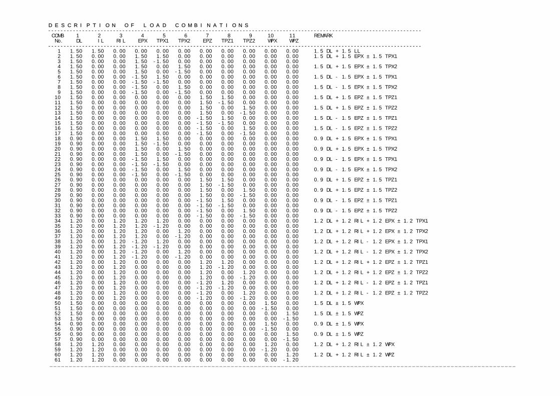
D E S C R I P T I O N O F L O A D C O M B I N A T I O N S ------------------------------------------------------------------------------------------------------------------------- COMB 1 2 3 4 5 6 7 8 9 10 11 REMARK No. DL IL RIL EPX TPX1 TPX2 EPZ TPZ1 TPZ2 WPX WPZ ------------------------------------------------------------------------------------------------------------------------- 1 1.50 1.50 0.00 0.00 0.00 0.00 0.00 0.00 0.00 0.00 0.00 1.5 DL + 1.5 LL 2 1.50 0.00 0.00 1.50 1.50 0.00 0.00 0.00 0.00 0.00 0.00 1.5 DL + 1.5 EPX ± 1.5 TPX1 3 1.50 0.00 0.00 1.50 -1.50 0.00 0.00 0.00 0.00 0.00 0.00 4 1.50 0.00 0.00 1.50 0.00 1.50 0.00 0.00 0.00 0.00 0.00 1.5 DL + 1.5 EPX ± 1.5 TPX2 5 1.50 0.00 0.00 1.50 0.00 -1.50 0.00 0.00 0.00 0.00 0.00 6 1.50 0.00 0.00 -1.50 1.50 0.00 0.00 0.00 0.00 0.00 0.00 1.5 DL - 1.5 EPX ± 1.5 TPX1 7 1.50 0.00 0.00 -1.50 -1.50 0.00 0.00 0.00 0.00 0.00 0.00 8 1.50 0.00 0.00 -1.50 0.00 1.50 0.00 0.00 0.00 0.00 0.00 1.5 DL - 1.5 EPX ± 1.5 TPX2 9 1.50 0.00 0.00 -1.50 0.00 -1.50 0.00 0.00 0.00 0.00 0.00 10 1.50 0.00 0.00 0.00 0.00 0.00 1.50 1.50 0.00 0.00 0.00 1.5 DL + 1.5 EPZ ± 1.5 TPZ1 11 1.50 0.00 0.00 0.00 0.00 0.00 1.50 -1.50 0.00 0.00 0.00 12 1.50 0.00 0.00 0.00 0.00 0.00 1.50 0.00 1.50 0.00 0.00 1.5 DL + 1.5 EPZ ± 1.5 TPZ2 13 1.50 0.00 0.00 0.00 0.00 0.00 1.50 0.00 -1.50 0.00 0.00 14 1.50 0.00 0.00 0.00 0.00 0.00 -1.50 1.50 0.00 0.00 0.00 1.5 DL - 1.5 EPZ ± 1.5 TPZ1 15 1.50 0.00 0.00 0.00 0.00 0.00 -1.50 -1.50 0.00 0.00 0.00 16 1.50 0.00 0.00 0.00 0.00 0.00 -1.50 0.00 1.50 0.00 0.00 1.5 DL - 1.5 EPZ ± 1.5 TPZ2 17 1.50 0.00 0.00 0.00 0.00 0.00 -1.50 0.00 -1.50 0.00 0.00 18 0.90 0.00 0.00 1.50 1.50 0.00 0.00 0.00 0.00 0.00 0.00 0.9 DL + 1.5 EPX ± 1.5 TPX1 19 0.90 0.00 0.00 1.50 -1.50 0.00 0.00 0.00 0.00 0.00 0.00 20 0.90 0.00 0.00 1.50 0.00 1.50 0.00 0.00 0.00 0.00 0.00 0.9 DL + 1.5 EPX ± 1.5 TPX2 21 0.90 0.00 0.00 1.50 0.00 -1.50 0.00 0.00 0.00 0.00 0.00 22 0.90 0.00 0.00 -1.50 1.50 0.00 0.00 0.00 0.00 0.00 0.00 0.9 DL - 1.5 EPX ± 1.5 TPX1 23 0.90 0.00 0.00 -1.50 -1.50 0.00 0.00 0.00 0.00 0.00 0.00 24 0.90 0.00 0.00 -1.50 0.00 1.50 0.00 0.00 0.00 0.00 0.00 0.9 DL - 1.5 EPX ± 1.5 TPX2 25 0.90 0.00 0.00 -1.50 0.00 -1.50 0.00 0.00 0.00 0.00 0.00 26 0.90 0.00 0.00 0.00 0.00 0.00 1.50 1.50 0.00 0.00 0.00 0.9 DL + 1.5 EPZ ± 1.5 TPZ1 27 0.90 0.00 0.00 0.00 0.00 0.00 1.50 -1.50 0.00 0.00 0.00 28 0.90 0.00 0.00 0.00 0.00 0.00 1.50 0.00 1.50 0.00 0.00 0.9 DL + 1.5 EPZ ± 1.5 TPZ2 29 0.90 0.00 0.00 0.00 0.00 0.00 1.50 0.00 -1.50 0.00 0.00 30 0.90 0.00 0.00 0.00 0.00 0.00 -1.50 1.50 0.00 0.00 0.00 0.9 DL - 1.5 EPZ ± 1.5 TPZ1 31 0.90 0.00 0.00 0.00 0.00 0.00 -1.50 -1.50 0.00 0.00 0.00 32 0.90 0.00 0.00 0.00 0.00 0.00 -1.50 0.00 1.50 0.00 0.00 0.9 DL - 1.5 EPZ ± 1.5 TPZ2 33 0.90 0.00 0.00 0.00 0.00 0.00 -1.50 0.00 -1.50 0.00 0.00 34 1.20 0.00 1.20 1.20 1.20 0.00 0.00 0.00 0.00 0.00 0.00 1.2 DL + 1.2 RIL + 1.2 EPX ± 1.2 TPX1 35 1.20 0.00 1.20 1.20 -1.20 0.00 0.00 0.00 0.00 0.00 0.00 36 1.20 0.00 1.20 1.20 0.00 1.20 0.00 0.00 0.00 0.00 0.00 1.2 DL + 1.2 RIL + 1.2 EPX ± 1.2 TPX2 37 1.20 0.00 1.20 1.20 0.00 -1.20 0.00 0.00 0.00 0.00 0.00 38 1.20 0.00 1.20 -1.20 1.20 0.00 0.00 0.00 0.00 0.00 0.00 1.2 DL + 1.2 RIL - 1.2 EPX ± 1.2 TPX1 39 1.20 0.00 1.20 -1.20 -1.20 0.00 0.00 0.00 0.00 0.00 0.00 40 1.20 0.00 1.20 -1.20 0.00 1.20 0.00 0.00 0.00 0.00 0.00 1.2 DL + 1.2 RIL - 1.2 EPX ± 1.2 TPX2 41 1.20 0.00 1.20 -1.20 0.00 -1.20 0.00 0.00 0.00 0.00 0.00 42 1.20 0.00 1.20 0.00 0.00 0.00 1.20 1.20 0.00 0.00 0.00 1.2 DL + 1.2 RIL + 1.2 EPZ ± 1.2 TPZ1 43 1.20 0.00 1.20 0.00 0.00 0.00 1.20 -1.20 0.00 0.00 0.00 44 1.20 0.00 1.20 0.00 0.00 0.00 1.20 0.00 1.20 0.00 0.00 1.2 DL + 1.2 RIL + 1.2 EPZ ± 1.2 TPZ2 45 1.20 0.00 1.20 0.00 0.00 0.00 1.20 0.00 -1.20 0.00 0.00 46 1.20 0.00 1.20 0.00 0.00 0.00 -1.20 1.20 0.00 0.00 0.00 1.2 DL + 1.2 RIL - 1.2 EPZ ± 1.2 TPZ1 47 1.20 0.00 1.20 0.00 0.00 0.00 -1.20 -1.20 0.00 0.00 0.00 48 1.20 0.00 1.20 0.00 0.00 0.00 -1.20 0.00 1.20 0.00 0.00 1.2 DL + 1.2 RIL - 1.2 EPZ ± 1.2 TPZ2 49 1.20 0.00 1.20 0.00 0.00 0.00 -1.20 0.00 -1.20 0.00 0.00 50 1.50 0.00 0.00 0.00 0.00 0.00 0.00 0.00 0.00 1.50 0.00 1.5 DL ± 1.5 WPX 51 1.50 0.00 0.00 0.00 0.00 0.00 0.00 0.00 0.00 -1.50 0.00 52 1.50 0.00 0.00 0.00 0.00 0.00 0.00 0.00 0.00 0.00 1.50 1.5 DL ± 1.5 WPZ 53 1.50 0.00 0.00 0.00 0.00 0.00 0.00 0.00 0.00 0.00 -1.50 54 0.90 0.00 0.00 0.00 0.00 0.00 0.00 0.00 0.00 1.50 0.00 0.9 DL ± 1.5 WPX 55 0.90 0.00 0.00 0.00 0.00 0.00 0.00 0.00 0.00 -1.50 0.00 56 0.90 0.00 0.00 0.00 0.00 0.00 0.00 0.00 0.00 0.00 1.50 0.9 DL ± 1.5 WPZ 57 0.90 0.00 0.00 0.00 0.00 0.00 0.00 0.00 0.00 0.00 -1.50 58 1.20 1.20 0.00 0.00 0.00 0.00 0.00 0.00 0.00 1.20 0.00 1.2 DL + 1.2 RIL ± 1.2 WPX 59 1.20 1.20 0.00 0.00 0.00 0.00 0.00 0.00 0.00 -1.20 0.00 60 1.20 1.20 0.00 0.00 0.00 0.00 0.00 0.00 0.00 0.00 1.20 1.2 DL + 1.2 RIL ± 1.2 WPZ 61 1.20 1.20 0.00 0.00 0.00 0.00 0.00 0.00 0.00 0.00 -1.20
-------------------------------------------------------------------------------------------------------------------------
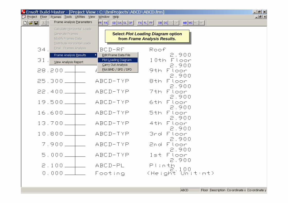
Select Plot Loading Diagram option from Frame Analysis Results.
Select Plot Loading Diagram option from Frame Analysis Results.
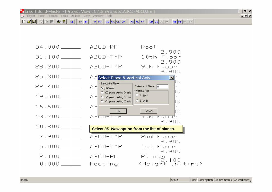
Select 3D View option from the list of planes.Select 3D View option from the list of planes.
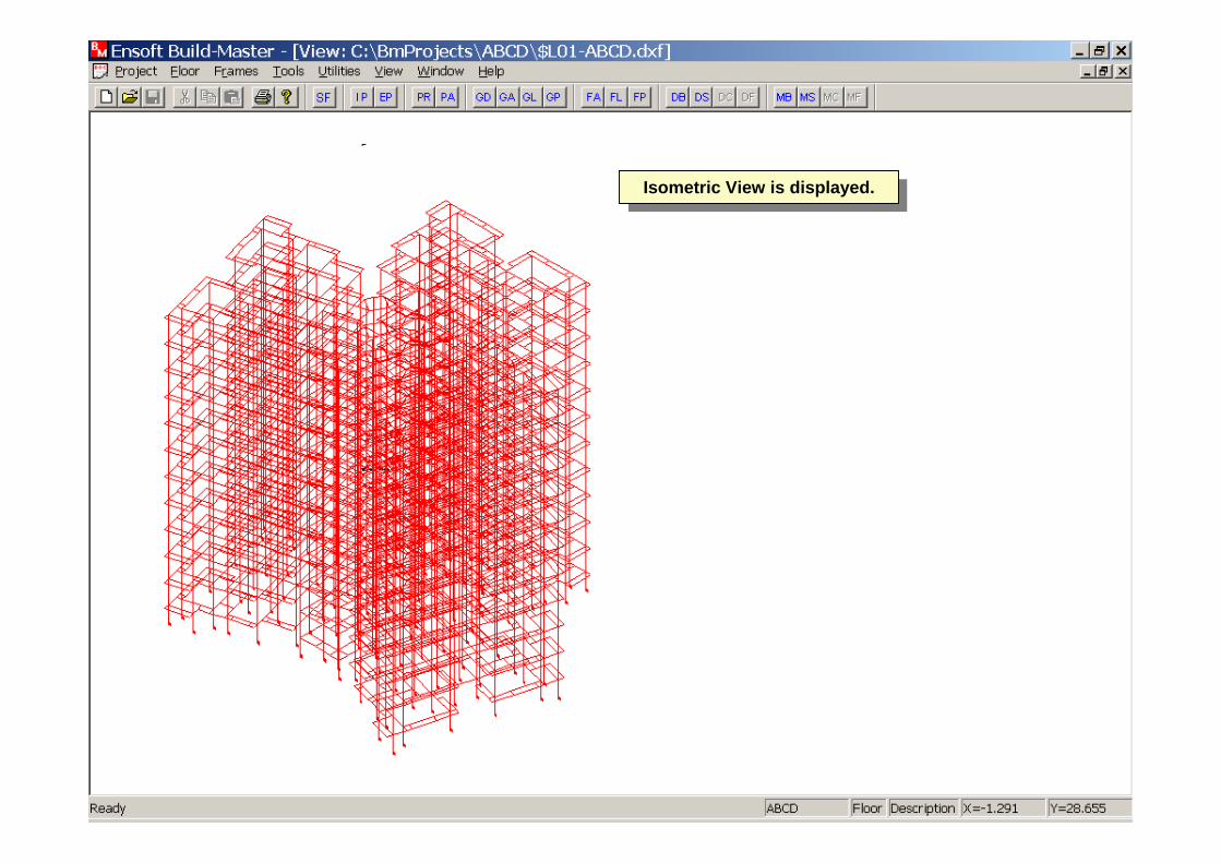
Isometric View is displayed.Isometric View is displayed.
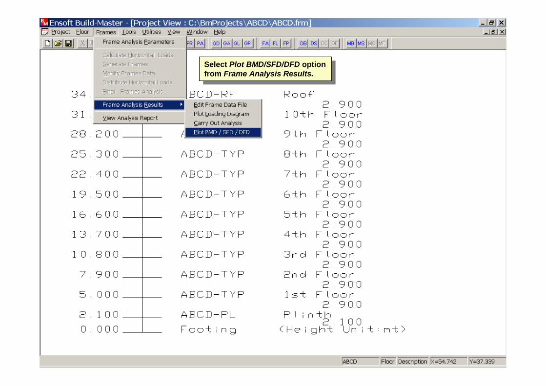
Select Plot BMD/SFD/DFD option from Frame Analysis Results.
Select Plot BMD/SFD/DFD option from Frame Analysis Results.

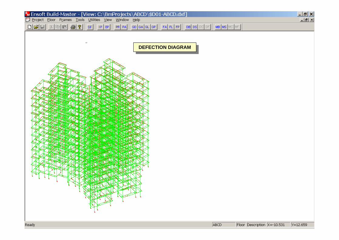
DEFECTION DIAGRAMDEFECTION DIAGRAM
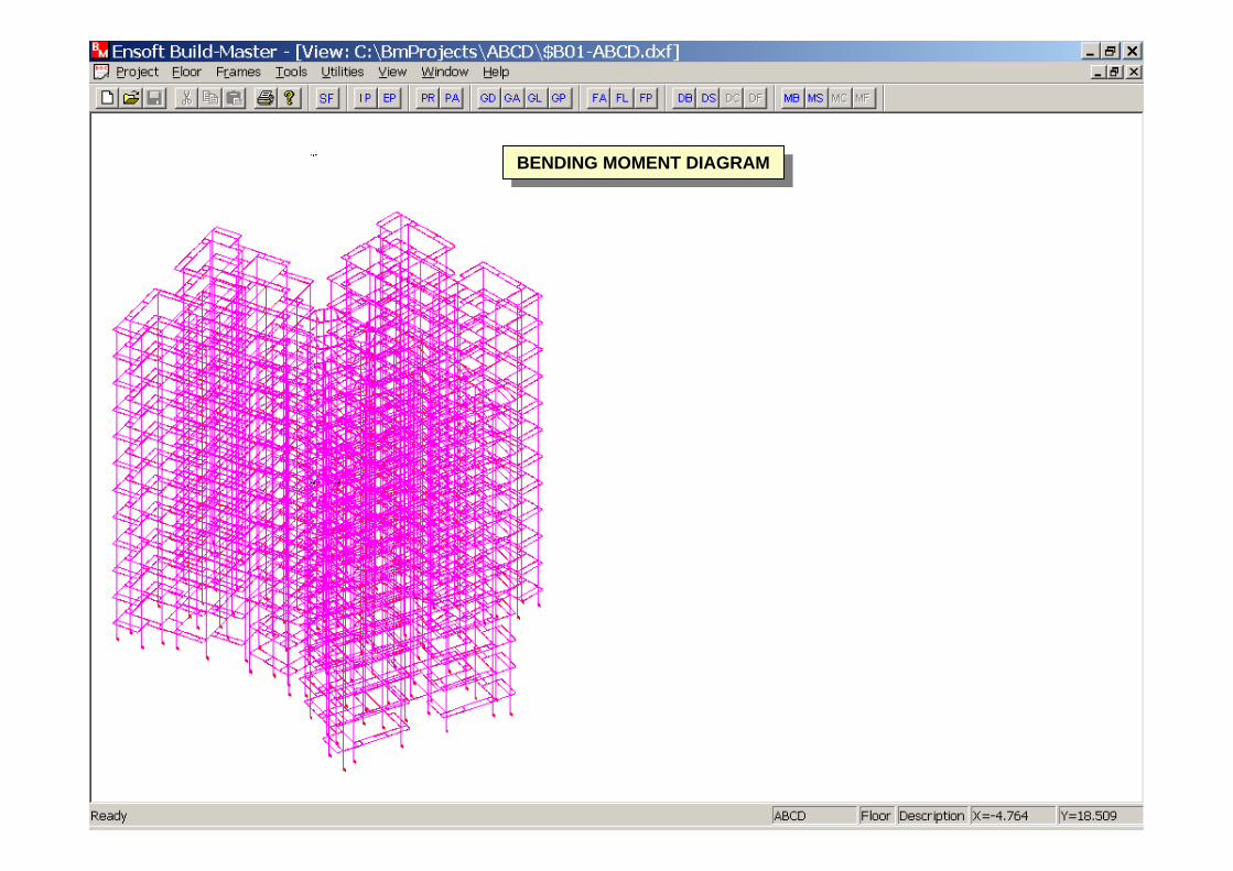
BENDING MOMENT DIAGRAMBENDING MOMENT DIAGRAM
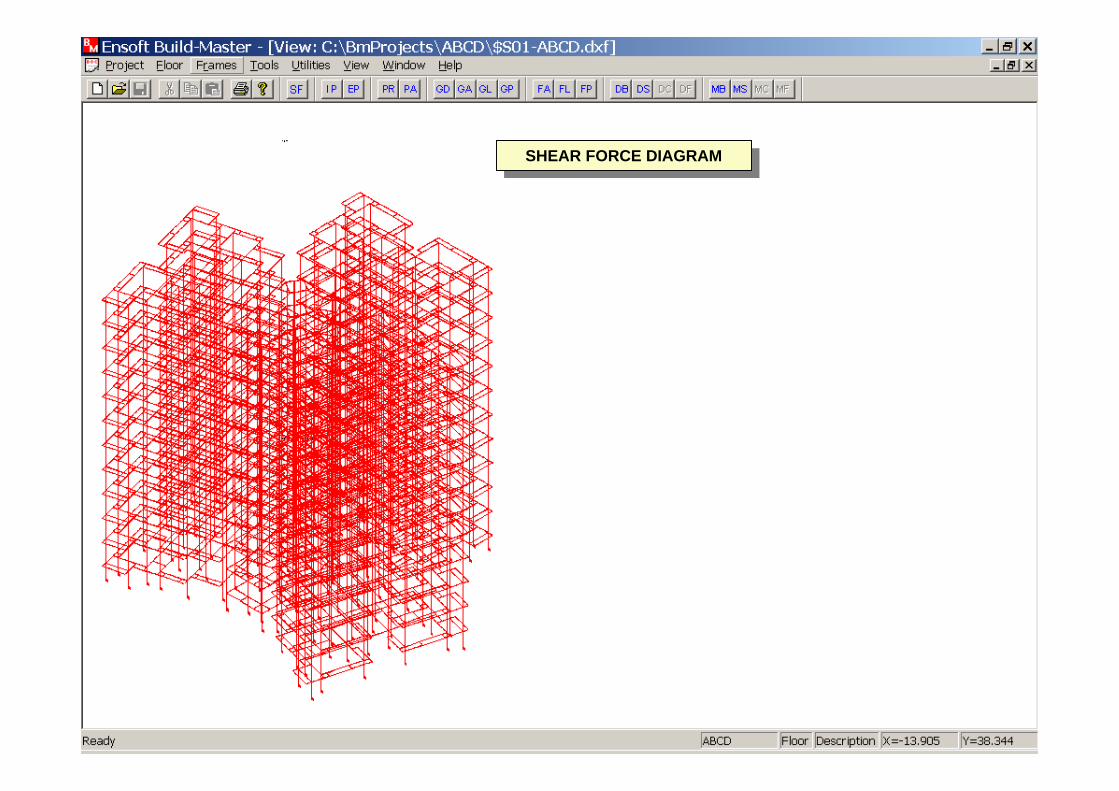
SHEAR FORCE DIAGRAMSHEAR FORCE DIAGRAM
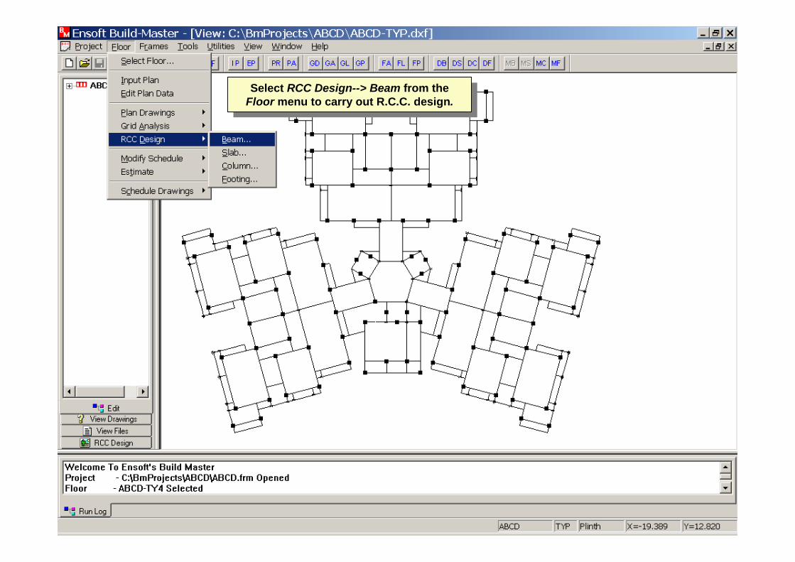
Select RCC Design--> Beam from the Floor menu to carry out R.C.C. design.Select RCC Design--> Beam from the
Floor menu to carry out R.C.C. design.
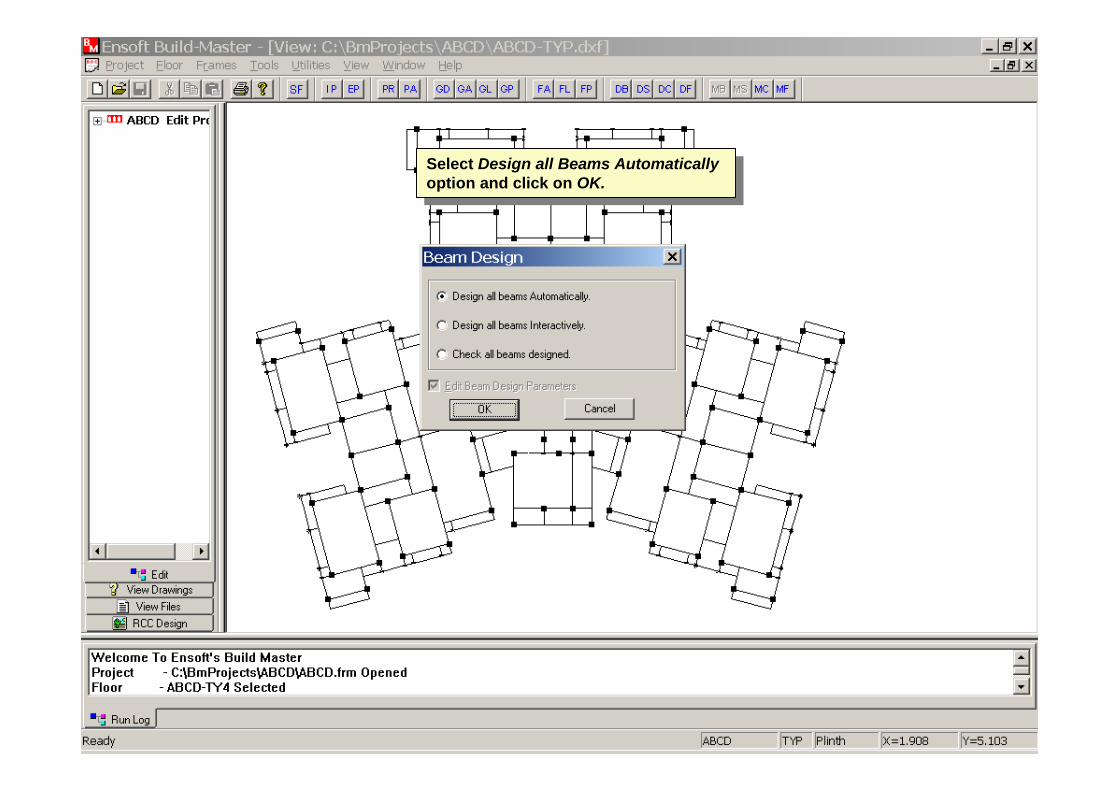
Select Design all Beams Automatically option and click on OK.
Select Design all Beams Automatically option and click on OK.

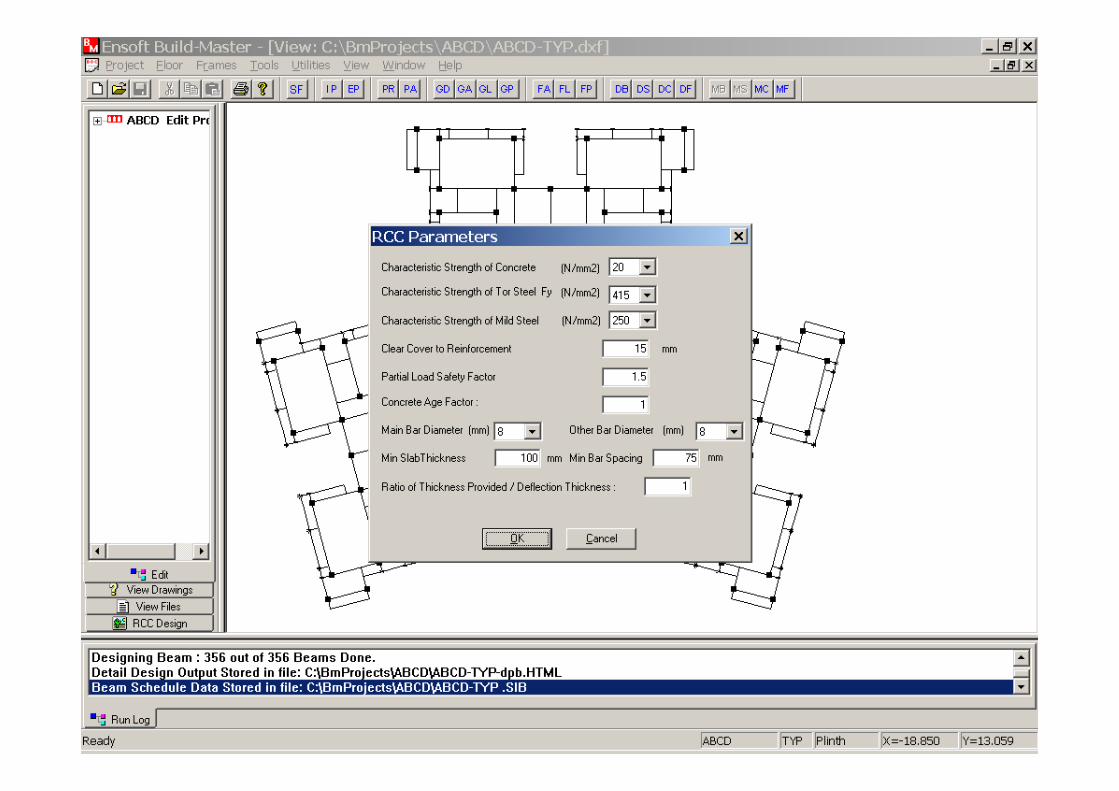
Select RCC Parameters as shown and click OK.
Select RCC Parameters as shown and click OK.
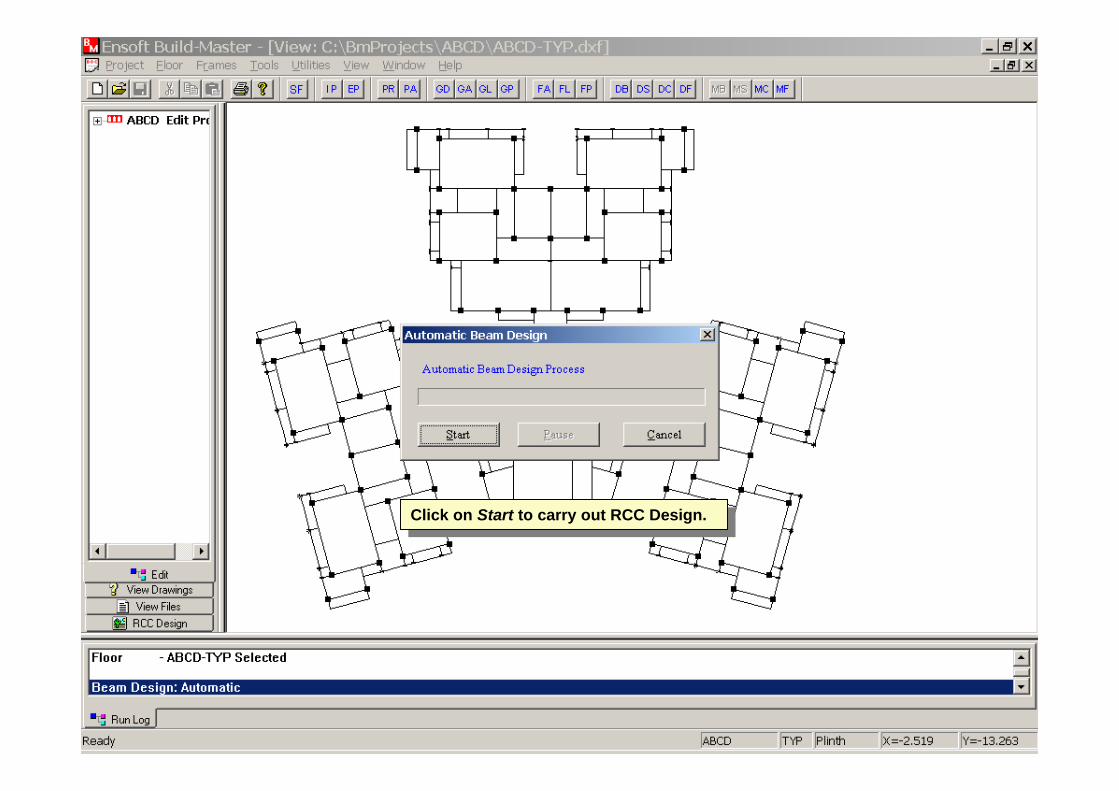
Click on Start to carry out RCC Design.Click on Start to carry out RCC Design.
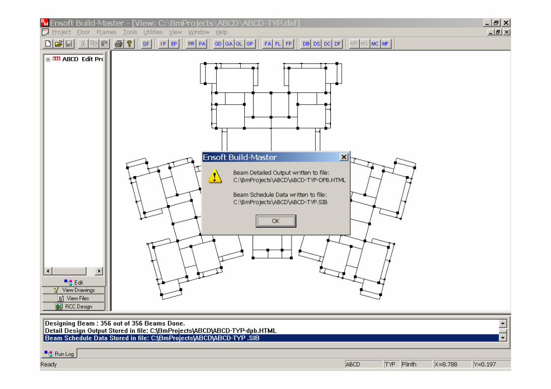

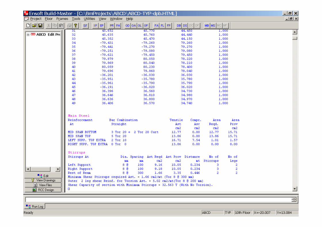
RCC Design output for Beams is displayed.RCC Design output for Beams is displayed.
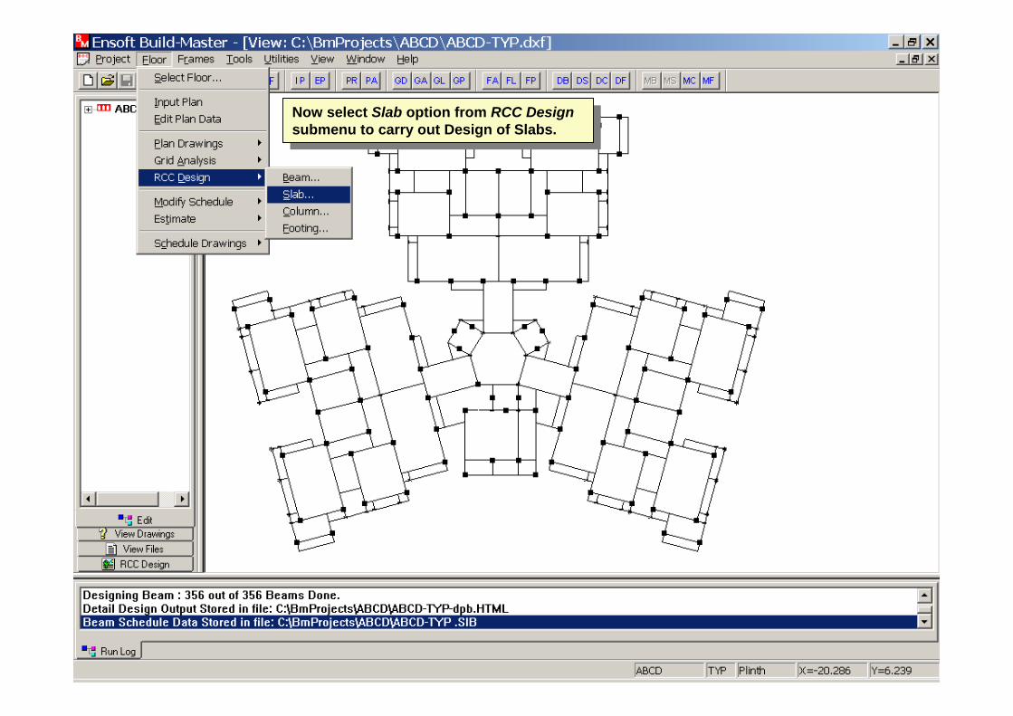
Now select Slab option from RCC Designsubmenu to carry out Design of Slabs.
Now select Slab option from RCC Designsubmenu to carry out Design of Slabs.
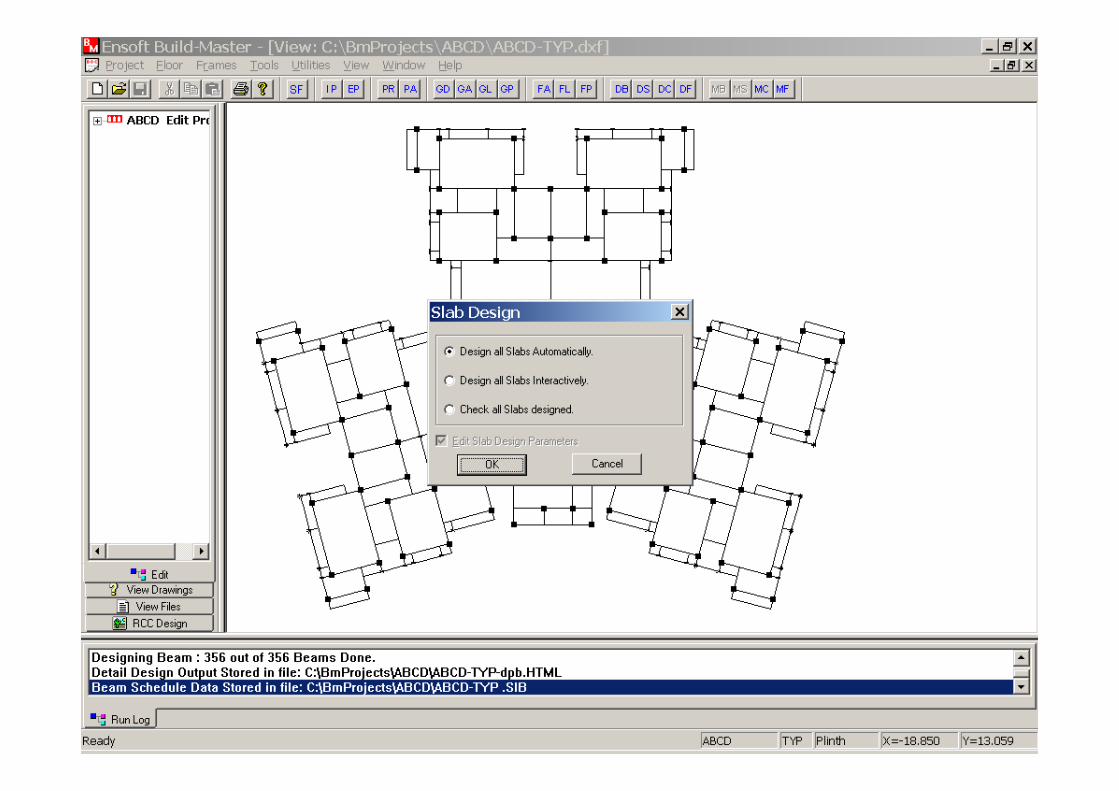
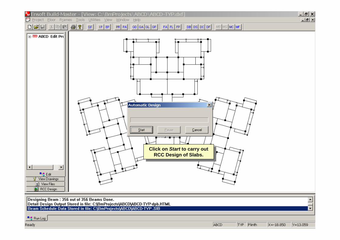
Click on Start to carry out RCC Design of Slabs.
Click on Start to carry out RCC Design of Slabs.


RCC Design output for Slabs is displayed.RCC Design output for Slabs is displayed.
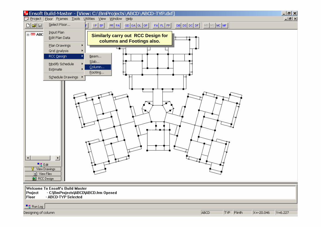
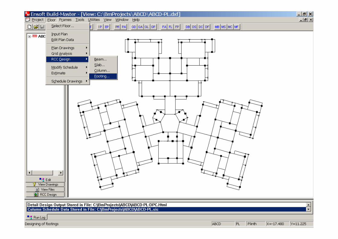
Similarly carry out RCC Design for columns and Footings also.
Similarly carry out RCC Design for columns and Footings also.
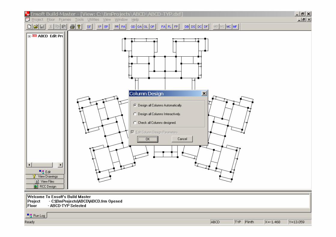

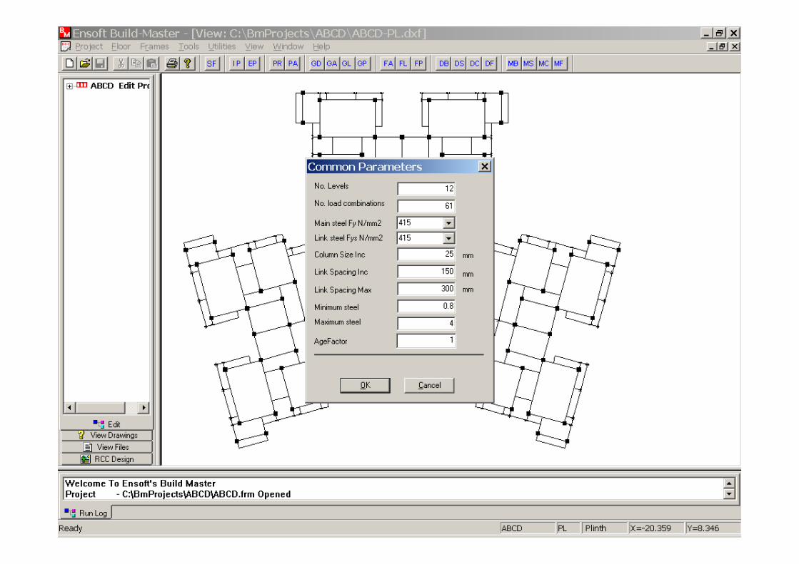
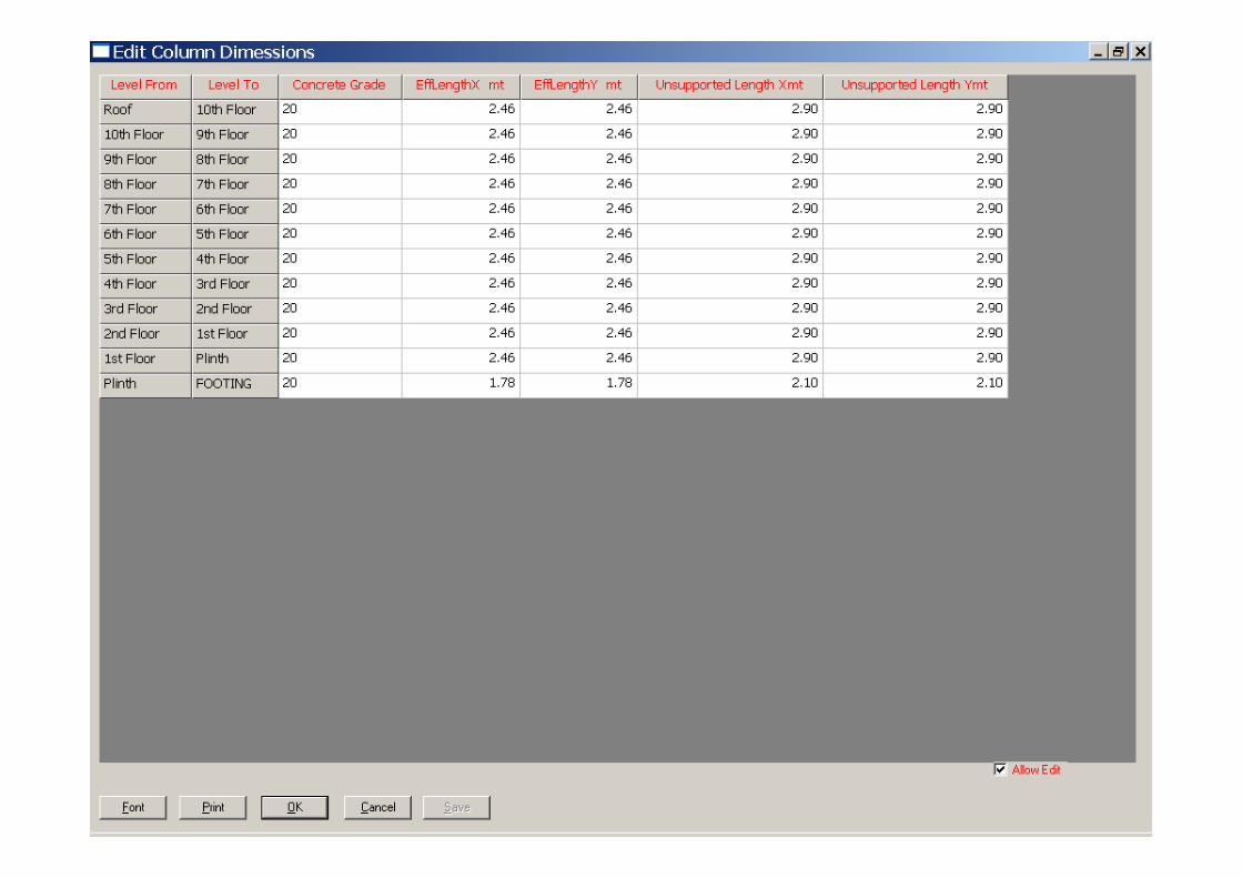
Enter Design Parameters as shown.Enter Design Parameters as shown.
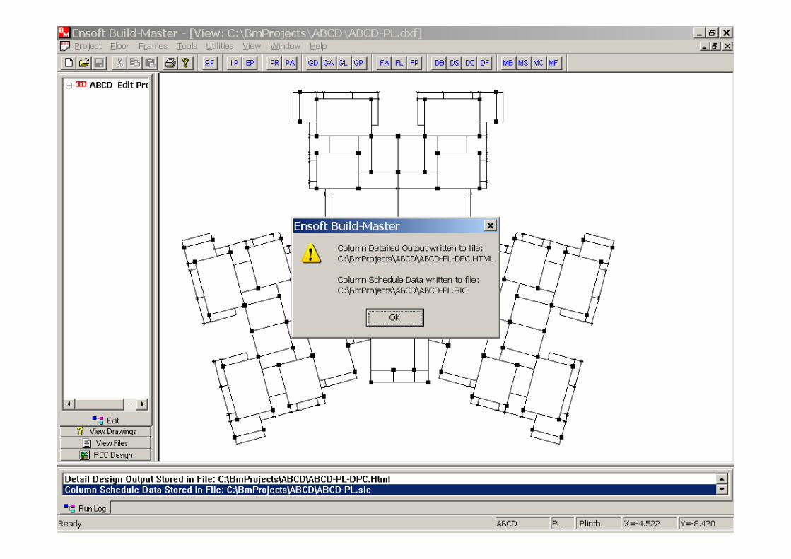

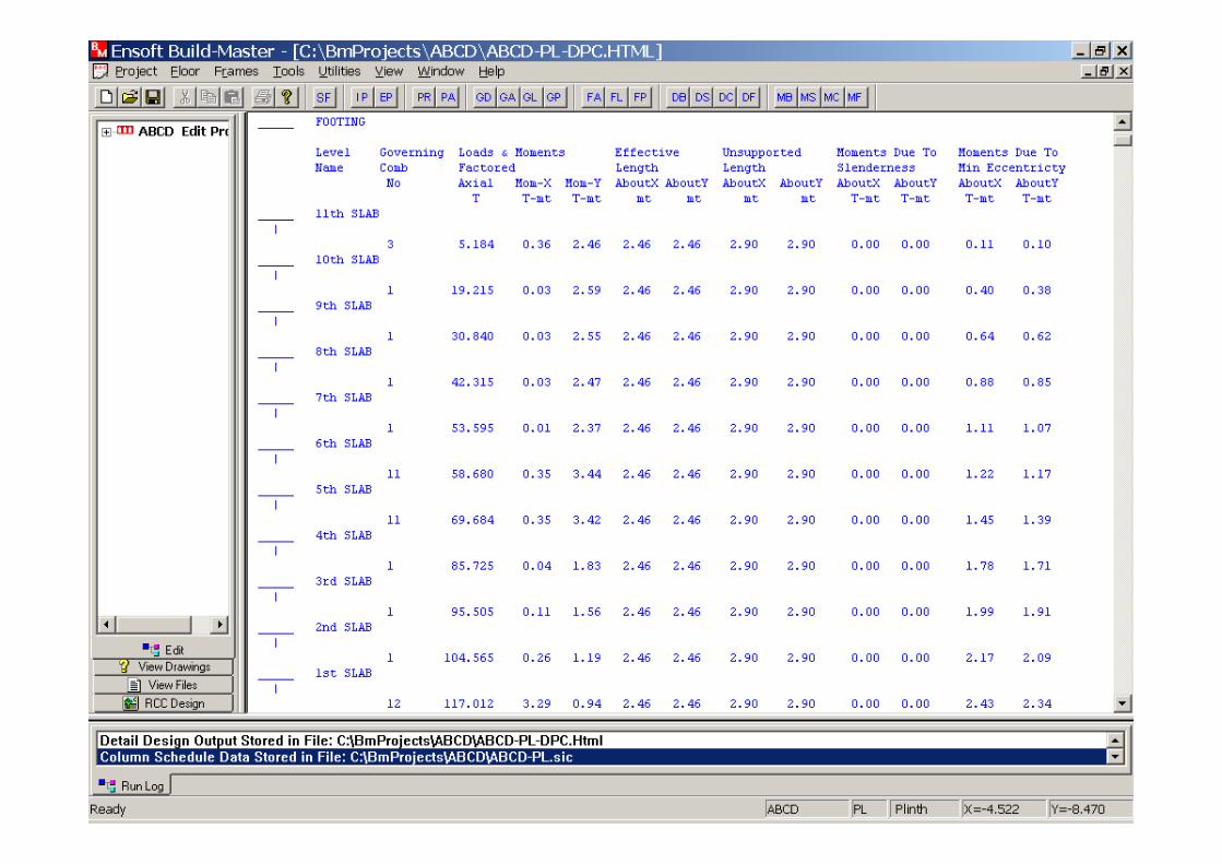
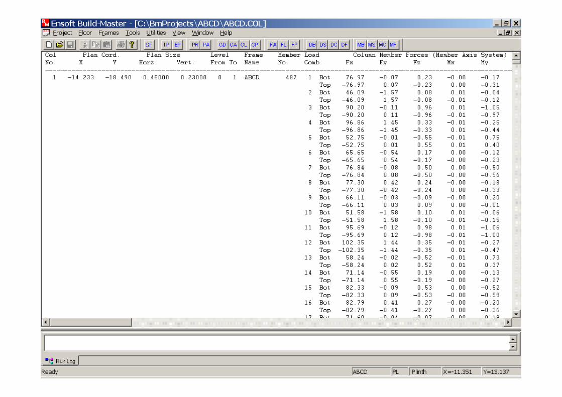
RCC Design output for columns is displayed.RCC Design output for columns is displayed.

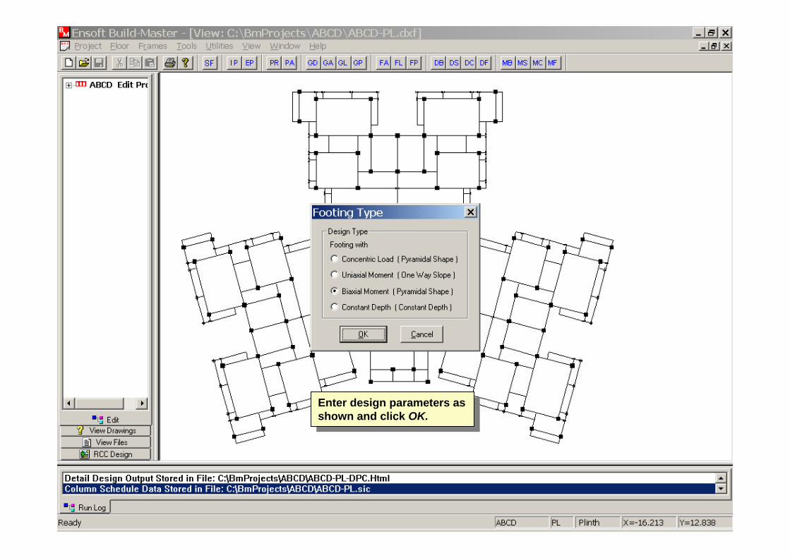
Enter design parameters as shown and click OK.
Enter design parameters as shown and click OK.
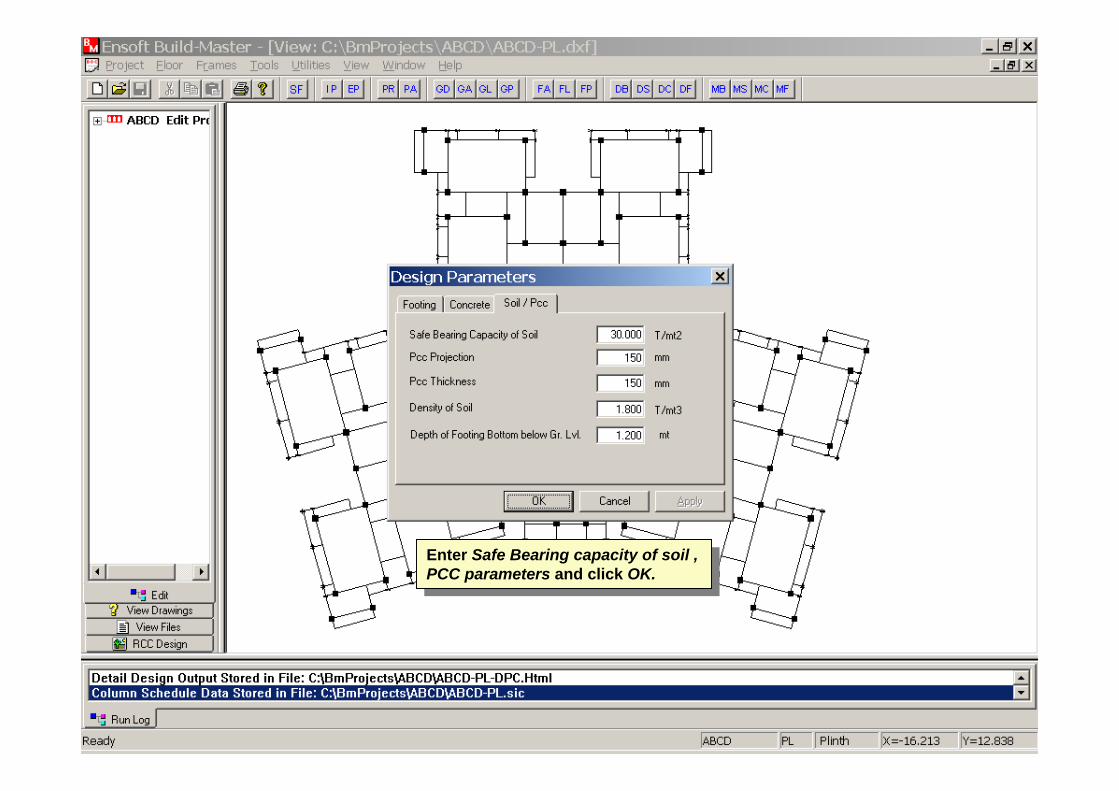
Enter Safe Bearing capacity of soil , PCC parameters and click OK.
Enter Safe Bearing capacity of soil , PCC parameters and click OK.
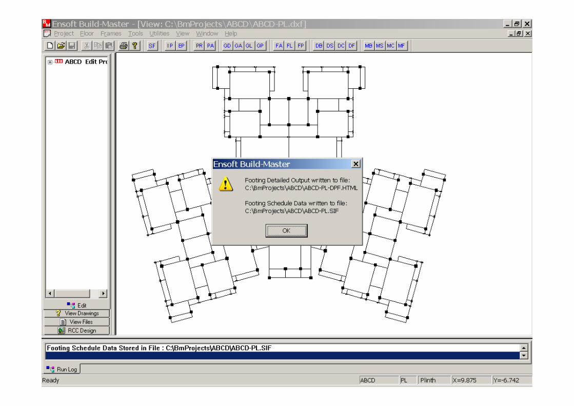
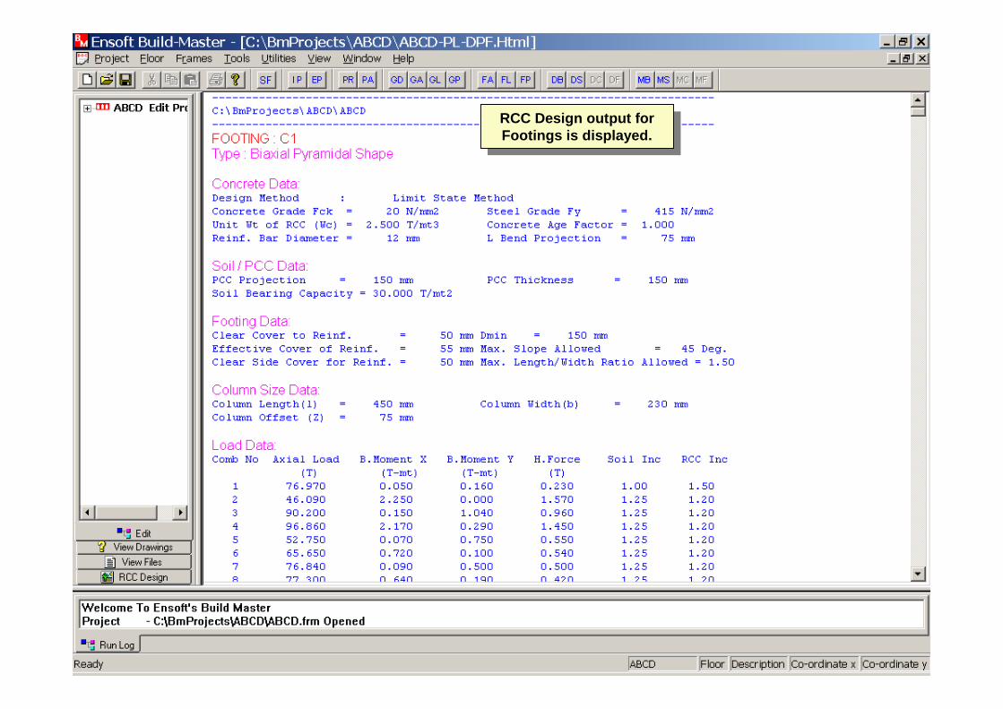
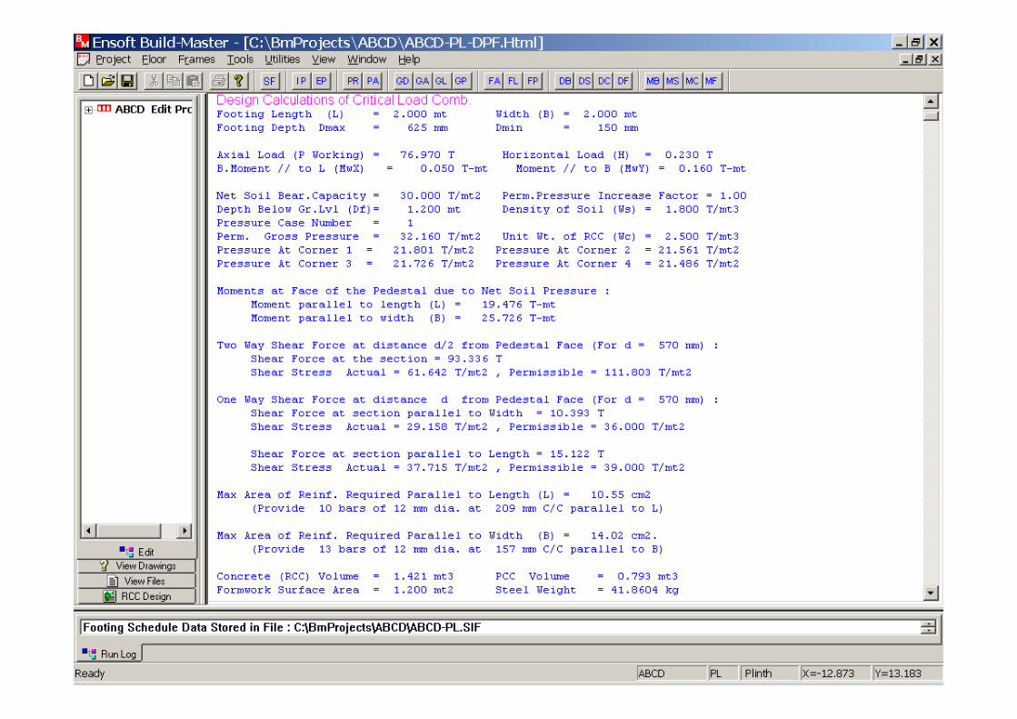
RCC Design output for Footings is displayed.
RCC Design output for Footings is displayed.

Foundation Plan can be viewed now by selecting that option from Plan Drawings.Foundation Plan can be viewed now by
selecting that option from Plan Drawings.
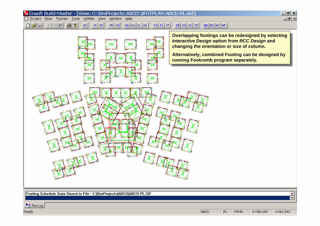
Overlapping footings can be redesigned by selecting Interactive Design option from RCC Design and changing the orientation or size of column.
Alternatively, combined Footing can be designed by running Footcomb program separately.
Overlapping footings can be redesigned by selecting Interactive Design option from RCC Design and changing the orientation or size of column.
Alternatively, combined Footing can be designed by running Footcomb program separately.
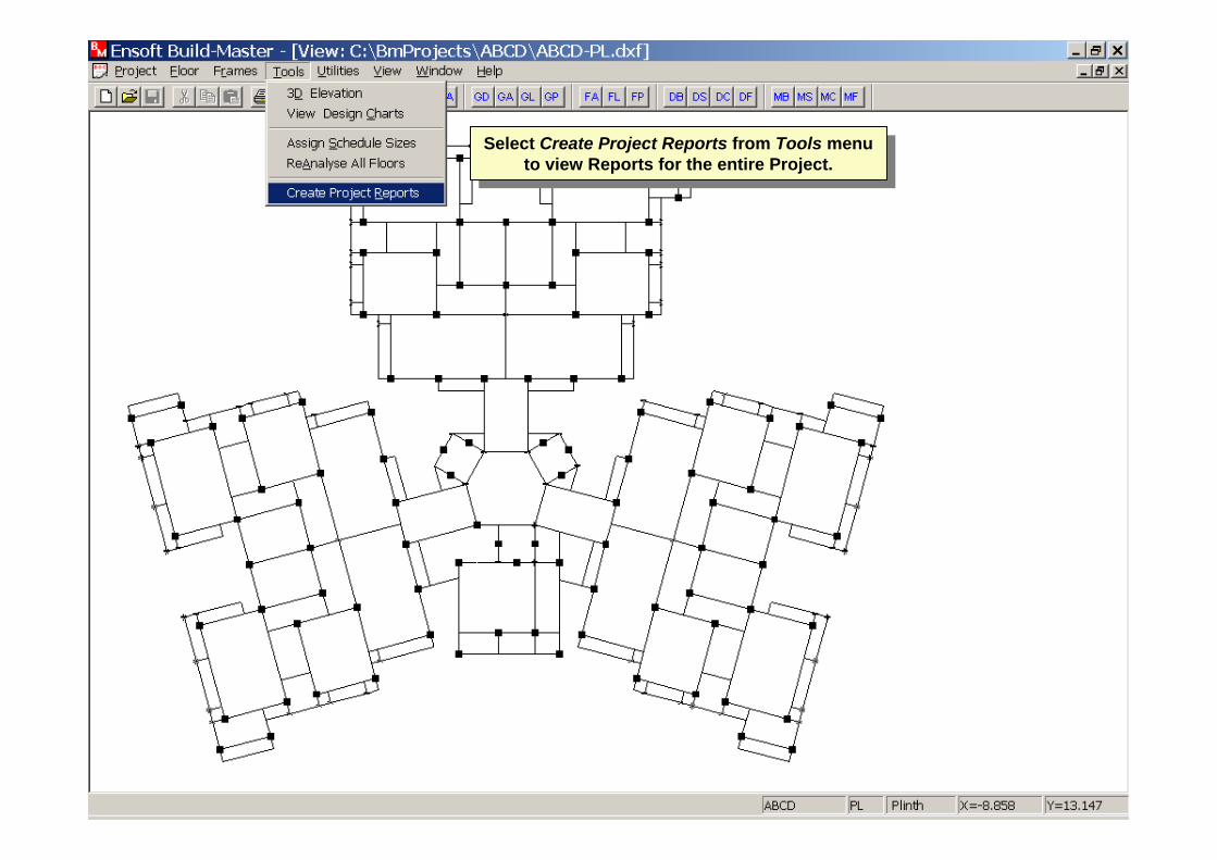
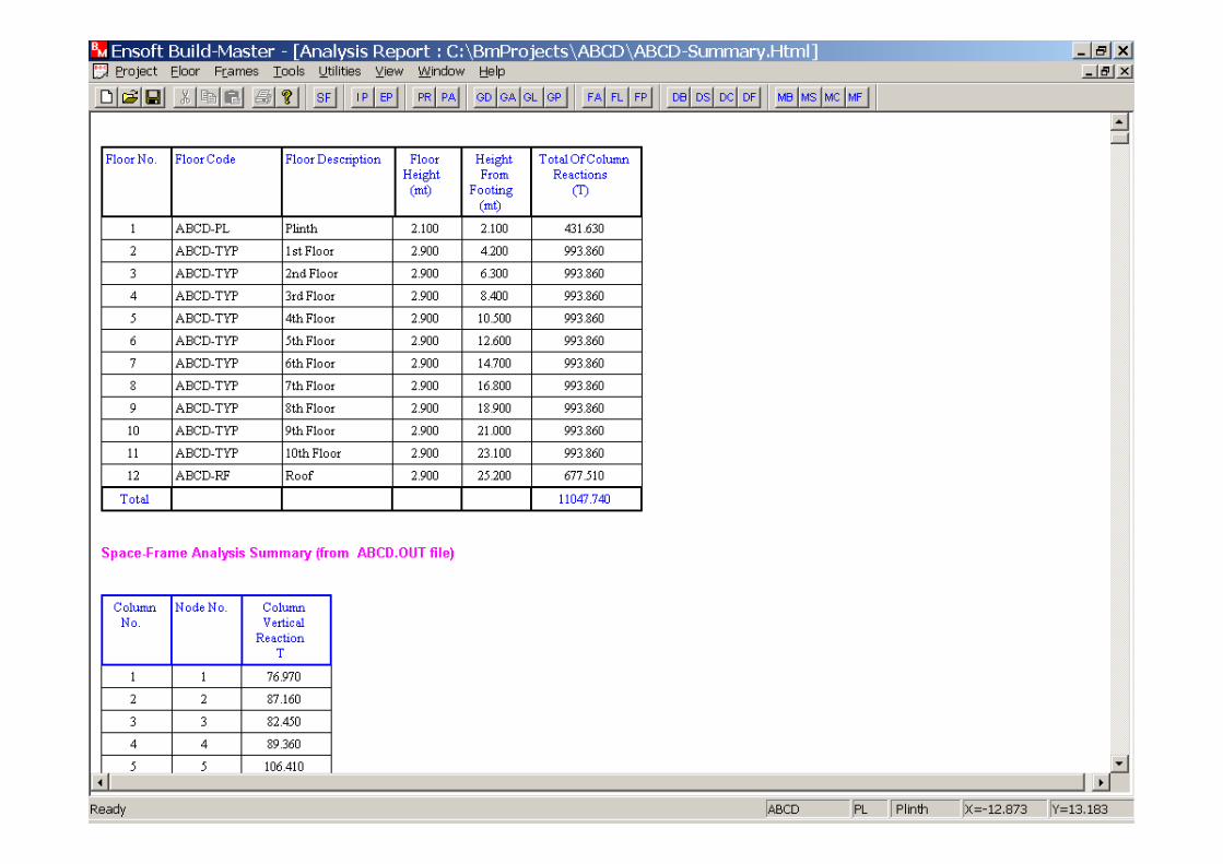
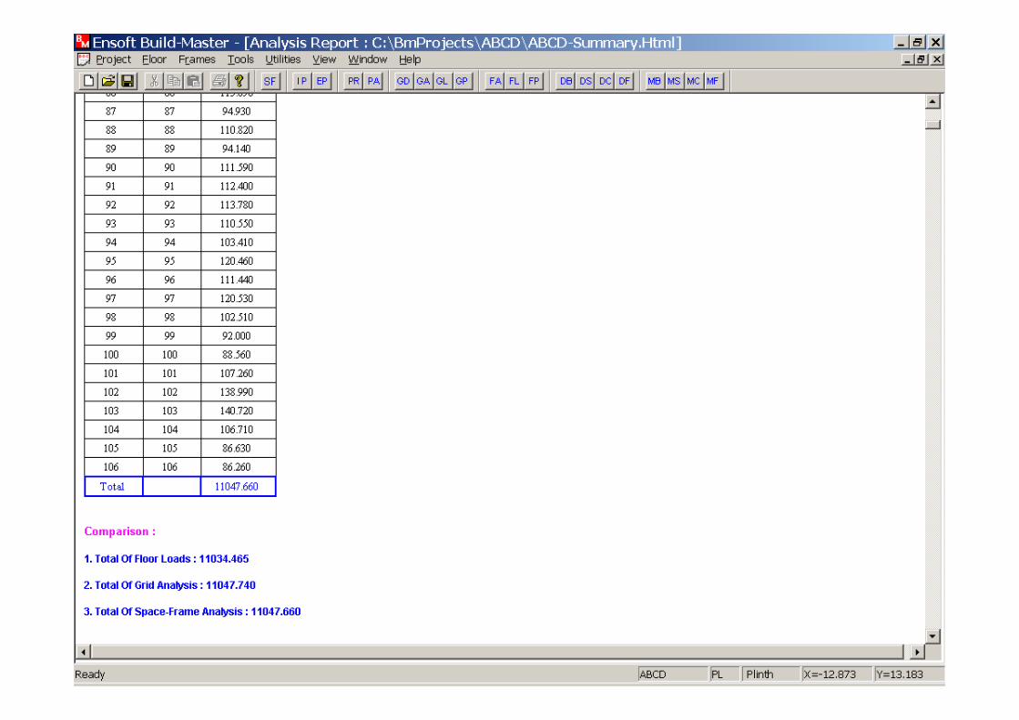
Select Create Project Reports from Tools menu to view Reports for the entire Project.
Select Create Project Reports from Tools menu to view Reports for the entire Project.

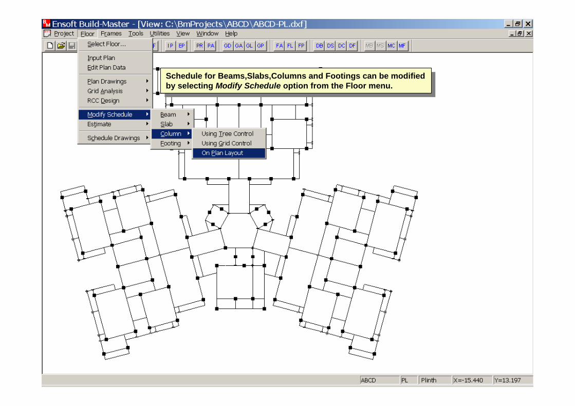
Schedule for Beams,Slabs,Columns and Footings can be modified by selecting Modify Schedule option from the Floor menu.
Schedule for Beams,Slabs,Columns and Footings can be modified by selecting Modify Schedule option from the Floor menu.


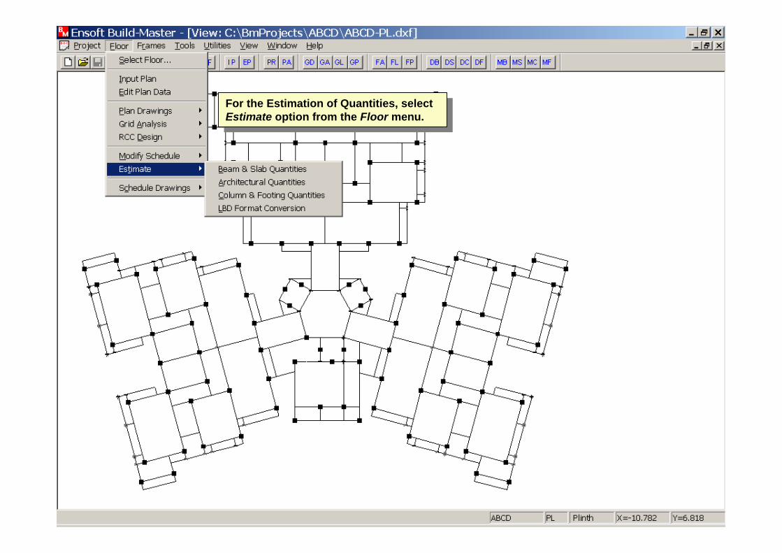
For the Estimation of Quantities, select Estimate option from the Floor menu.
For the Estimation of Quantities, select Estimate option from the Floor menu.
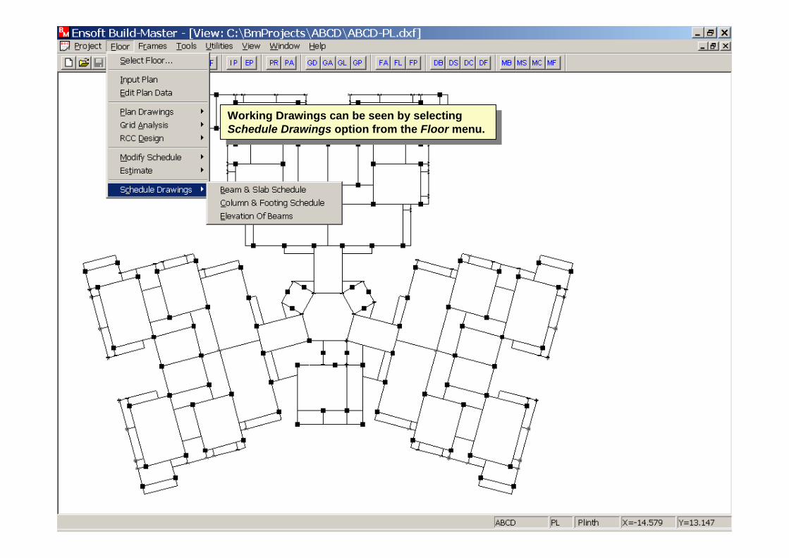
Working Drawings can be seen by selecting Schedule Drawings option from the Floor menu.
Working Drawings can be seen by selecting Schedule Drawings option from the Floor menu.

THANK YOU
ENSOFTENSOFT