BUCKLING COEFFICIENTS FOR SANDWICH CYLINDERS OF FINITE ...
29
U.S. DEPARTMENT OF AGRICULTURE • FOREST SERVICE •FOREST PRODUCTS LABORATORY • MADlSON, WIS. In Cooperation with the University of Wisconsin U. S. FOREST SERVICE RESEARCH NOTE FPL- 0104 SEPTEMBER 1965 BUCKLING COEFFICIENTS FOR SANDWICH CYLINDERS OF FINITE LENGTH UNDER UNIFORM EXTERNAL LATERAL PRESSURE This Report is One of a Series Issued in Cooperation with the MIL-HDBK-23 WORKING GROUP ON COMPOSITE CONSTRUCTION FOR FLIGHT VEHICLES of the Departments of the AIR FORCE, NAVY, AND COMMERCE
Transcript of BUCKLING COEFFICIENTS FOR SANDWICH CYLINDERS OF FINITE ...

U.S. DEPARTMENT OF AGRICULTURE • FOREST SERVICE •FOREST PRODUCTS LABORATORY • MADlSON, WIS. In Cooperation with the University of Wisconsin
U. S. FOREST SERVICE RESEARCH NOTE
FPL-0104 SEPTEMBER 1965
BUCKLING COEFFICIENTS FOR SANDWICH CYLINDERS OF FINITE LENGTH UNDER UNIFORM EXTERNAL LATERAL PRESSURE
This Report is One of a Series Issued in Cooperation with the MIL-HDBK-23 WORKING GROUP ON COMPOSITE CONSTRUCTION FOR FLIGHT VEHICLES of the Departments of the AIR FORCE, NAVY, AND COMMERCE

ABSTRACT
This Note contains curves of buckling coefficients and formulas for the calculation of the critical external pressure of finite length, circular cylindrical shells with sandwich walls. The facings of the sandwich are isotropic, of equal or unequal thickness, of the same or different material, and their individual stiffness is not taken into account. The sandwich core is isotropic or orthotropic having natural axes in the axial, tangential, and radial directions of the cylinder. If the cores are very rigid, the method yields results that are substantially those of von Mises.
ddobson
Underline

BUCKLING COEFFICIENTS FOR SANDWICH CYLINDERS
OF FINITE LENGTH UNDER UNIFORM EXTERNAL
LATERAL PRESSURE 1,2
ByE. W. KUENZI, Engineer B. BOHANNAN, Engineer
and G. H. STEVENS, Engineer
Forest Products Laboratory,3-Forest Service U.S. Department of Agriculture
Introduction
Design curves for the critical external radial pressure of circular cylindrical shells with sandwich walls, calculated according to the formulas developed at the Forest Products Laboratory (9),4 are presented in this report. The sandwich cylinder walls have isotropic facings of equal or unequal thickness, and of the same or different materials, and orthotropic or isotropic cores. It is assumed that Poisson's ratio is the same for both facings. The natural axes of the orthotropic cores are axial, tangential, and radial. These formulas reduce substantially to those developedby von Mises (7, 10, 14) when the core is very rigid.
1This Note is the latest revision of "Design Curves for the Buckling of Sandwich Cylinders of Finite Length under Uniform External Lateral Pressure," by Charles B. Norris and John J. Zahn. It was originally issued as Forest Products Lab. Rpt. 1869 in 1959, and revised as U.S. Forest Service Research Note FPL-07 in 1963.
2This progress report is one of a series (ANC-23, Item 57-3) prepared and distributed by the Forest Products Laboratory under U.S. Navy, Bureau of Naval Weapons Order No. 19-65-8005 WEPS and U.S. Air Force Contract NO. DO 33(615)65-5002. Results here reported are preliminary and may be revised as additional data become available.
3Maintained at Madison, Wis., in cooperation with the University of Wisconsin. 4Underlined numbers in parentheses refer to Literature Cited at the end of
this report.
FPL-0104

Much investigative work has been done on isotropic cylindrical shells subjected to external pressure since Forest Products Laboratory Report 1844-B, giving theoretical analysis of sandwich cylinders, was published, It was found that experiment sometimes yields critical loads that are less than those predicted by von Mises' theory (13). This has been attributed to two causes. First, the experimental cylinders contained imperfections that lowered the critical load (1, 2, 3, 8, 12). Second, energy levels associated with postbuckling configurations of the cylinder are lower than those just at buckling. The energy levels associated with postbuckling may be reached without snap-through buckling. The energy necessary for snap-through buckling may be supplied by vibration or shocks (4, 5, 6, 8). The curves in this report do not consider snap-through buckling or cylinders with imperfections.Sandwich cylinder walls, however, are much more perfect than their solid counterparts because they are thicker and the effect of an imperfection is in proportion to the ratio of its amplitude to the thickness of the cylindrical shell wall. Also, the curves neglect the stiffnesses of the individual facings. These stiffnesses add to the critical loads when the cylinders are short, and it is for short cylinders that snap-through is likely to occur (6).
Development of Formula for Design Curves
The formulas presented in this report for calculating the critical external pressure and the buckling coefficient are based on the work presented in Forest Products Laboratory Reports 11844-A and 1844-B (9) with the followingnotation:
E1, E2 Modulus of elasticity of the outer facing (1) and inner facing (2),respectively.
µ Poisson‘s ratio,
θ Grz . Grθ
Grz Modulus of rigidity of core in the radial and axial directions.
Grθ Modulus of rigidity of core in the radial and tangential directions.
d Thickness of the sandwich.
h Distance between facing centroids.
t1, t2 Thickness of outer and inner faces, respectively.
r Mean radius of the sandwich cylinder.
L Length of the cylinder.
FPL-0104 -2-

β
R
N qr.
n Number of half-waves in the circumferences of the cylinder.
k
q The external critical pressure on the cylinder.
A few parameters of Report 1844-B were generalized to dissimilar facings as follows:
Report 1844-B Revised Parameter
These generalized parameters were combined with the notation and derivation of equations given in Report 1844-B. The critical external pressure was then found by solving the revised form of equation 51 of Report 1844-B for the buckling coefficient. The determinant was simplified by taking modulus of elasticity of the core (Ec) to be infinite. For most core materials, except possibly for low-density foams, Ec is sufficiently large so that this assumption yields only slightly high values of the critical pressure. Before Ec is allowed to approach infinity, the first, third, and fourth columns of
FPL-0104 -3-
V

the determinant are multiplied by Gzq. Then when Ec approaches infinity, the Ec
expressions in rows 3, 4, 5, and 6 of column 3 approach zero. Further simplification of the 6 by 6 determinant was made by taking µ to be 1/3, multiplying row 1 by
and row 2 by
Further reduction is accomplished by adding multiples of one row to another as indicated by the following sequence of substitutions, where subscriptsindicate row number counting down from the top:
These substitutions cause the expressions in rows 2, 3, 4, 5, and 6 of column 3 and those in rows 3, 4, 5, and 6 of column 6 to become zero, and the 6 by 6 determinant was readily reduced by minors to a 4 by 4 determinant. The radii a and
the b were eliminated by the following equations obtained from
the geometry of cylinder:
FPL-0104 -4-

and the following substitutions were made:
After setting this determinant equal to zero and solving for k, the critical pressure can be found by
This represents a theoretical solution for the critical pressure with the assumption that the sandwich core modulus of elasticity is infinite.
The determinant was further simplified by a few approximations without anysignificant loss of accuracy. Examination of the parameters and showed that is large in comparison to Therefore, any terms of
were taken as equal to
Making this simplification, the determinant reduces to the following expressions:
Row 1, column 1
Row 2, column 1
Row 3, column 1
Row 4, column 1
FPL-0104 -5-

Row 1, column 2
Row 2, column 2
Row 3, column 2
Row 4, column 2
Row 1, column 3
Row 2, column 3
0
Row 3, column 3
Row 4, column 3
Row 1, column 4
FPL-0104 -6-

Row 2, column 4
Row 3, column 4
Row 4, column 4
By setting this determinant equal to zero, the approximate solution for k is
To obtain this value of k, terms containing k2 and kα2 were neglected. It was also assumed that terms (1 ± mα) = 1 where m is a small whole number.
A lower and upper limit exist for the buckling coefficient k. The lower limit is associated with the infinitely long shell for which β = 0 and this limit from the approximate formula for k is given by
and for V = 0 this formula is minimum for n = 2 and is
FPL-0104 -7-
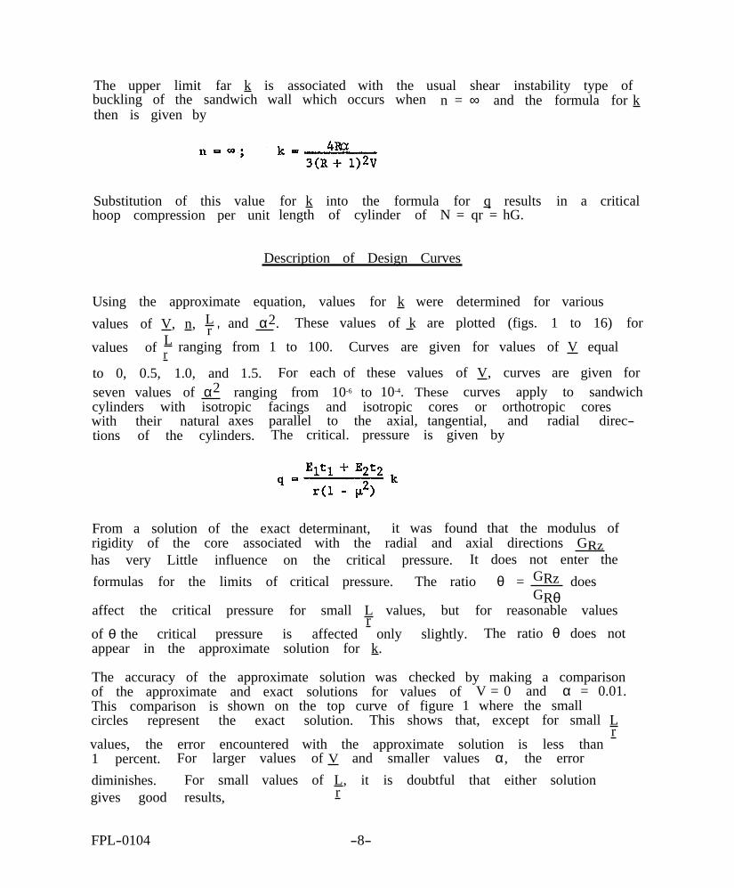
The upper limit far k is associated with the usual shear instability type of buckling of the sandwich wall which occurs when n = ∞ and the formula for k then is given by
Substitution of this value for k into the formula for q results in a critical hoop compression per unit length of cylinder of N = qr = hG.
Description of Design Curves
Using the approximate equation, values for k were determined for various values of V, n, L
r ' and α2. These values of k are plotted (figs. 1 to 16) for
values of L ranging from 1 to 100. Curves are given for values of V equalr to 0, 0.5, 1.0, and 1.5. For each of these values of V, curves are given for seven values of α2 ranging from 10-6 to 10-4. These curves apply to sandwich cylinders with isotropic facings and isotropic cores or orthotropic cores with their natural axes parallel to the axial, tangential, and radial directions of the cylinders. The critical. pressure is given by
From a solution of the exact determinant, it was found that the modulus of rigidity of the core associated with the radial and axial directions GRz has very Little influence on the critical pressure. It does not enter the formulas for the limits of critical pressure. The ratio θ = GRz does
GRθaffect the critical pressure for small L values, but for reasonable values
r of θ the critical pressure is affected only slightly. The ratio θ does not appear in the approximate solution for k.
The accuracy of the approximate solution was checked by making a comparison of the approximate and exact solutions for values of V = 0 and α = 0.01. This comparison is shown on the top curve of figure 1 where the small circles represent the exact solution. This shows that, except for small L
r values, the error encountered with the approximate solution is less than 1 percent. For larger values of V and smaller values α, the error diminishes. For small values of L, it is doubtful that either solution gives good results, r
FPL-0104 -8-
ddobson
Underline
ddobson
Underline
Literature Cited
(1) Bodner, S. R., and Berks, W. 1952, The effect of imperfections on the stress in a circular
cylindrical shell under hydrostatic pressure. PIBAL Rpt. 210, illus. Polytechnic Institute of Brooklyn.
(2) Donnell, L. H. 1956. Effect of imperfections on buckling of thin cylinders under
external pressure. Jour. Appl. Mech. 23(4).
(3) Galletly, G. D., and Bart, R. 1956. Effects of boundary conditions and initial out-of-roundness on
the strength of thin-walled cylinders subject to external hydrostatic pressure. Jour. Appl. Mech. 23(3).
(4) Kempner, Joseph, Pandolai, K. A. V., Patel, S. A., and Crouzet-Pascal, J. 1957. Post-buckling behavior of circular cylindrical shells under
hydrostatic pressure. Jour. Aero. Sci. 24(4).
(5) Kirstein, A. F., and Wenk, E. 1956. Observations of snap-through action in thin cylindrical shells
under external pressure. David Taylor Model Basin Rpt. 1062. U.S. Navy Dept.
(6) Langhaar, H. L., and Boresi, A. P. 1955. Snap-through and post-buckling behavior of cylindrical shells
under the action of external pressure. T. & A.M. Rpt. 80. Department of Theoretical and Applied Mechanics, University of Illinois.
(7) Mises, R. von 1929. The critical external pressure of cylindrical tubes under uniform
radial and axial load. Stodola-Festschrift, Zurich.
(8) Nash, William A. 1955. Effect of large deflections and initial imperfections on the
buckling of cylindrical shells subject to hydrostatic pressure. Jour. Aero. Sci. 22(4).
(9) Raville, Milton E. 1954. Analysis of long cylinders of sandwich construction under uniform
external lateral pressure. Forest Products Lab. Rpt. 1844, 23 pp., illus.; and supplementary Rpts. 1844-A(1955) and 1844-B (1955).
(10) Timoshenko, S. 1936. Theory of elastic stability. McGraw-Hill, New York.
FPL-0104 -9-

(11) U.S. Department of Defense. 1955. Sandwich construction for aircraft. Part II, Second Edition.
ANC-23 Bulletin, 115 pp., illus. Superintendent of Documents, U.S. Government Printing Office, Washington, D.C. 20402.
(12) Volmir, A. S. 1957. On the influence of initial imperfections on the stability of
cylindrical shells under external pressure. Dokladi Akad. Nauk SSSR (N. S.) 113: (2)291-293 (translated by M. D. Friedman, Inc., Heedham, Mass., V-124, 5 pp.)
(13) Wenk, E., Slankard, R. C., and Nash, W. A. 1954. Experimental analysis of the buckling of cylindrical shells
subjected to external hydrostatic pressure. Proc. Soc. Exp. Stress Anal. XII (1).
(14) Windenburg, D. F., and Trilling, C. 1934. Collapse by instability of thin cylindrical shells under external
pressure. Trans. American Society of Mechanical Engineers 56(11).
FPL-0104 -10- 1.-26

Figure 1.--Values of k for V = 0, and for
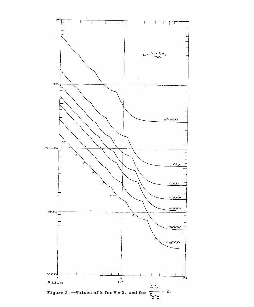
Figure 2.--Values of k for V = 0, and for
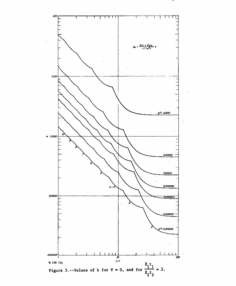
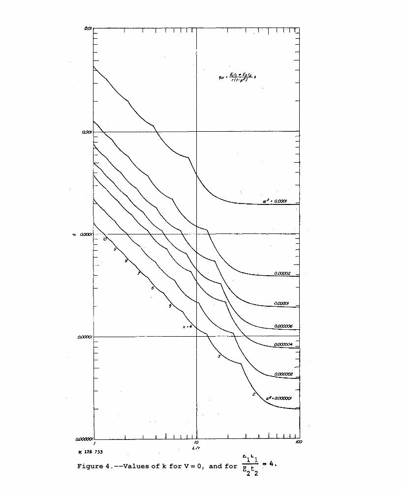
Figure 4.--Values of k for V = 0, and for
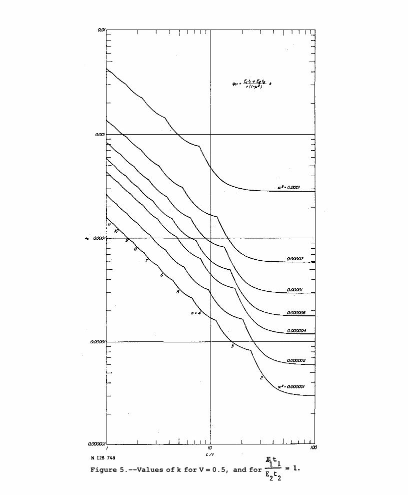
Figure 5.--Values of k for V = 0.5, and for E t

Figure 6.--Values of k for V = 0.5, and for E t

Figure 7.--Valuesof k for V = 0.5, and for E t

Figure 8.--Values of k for V = 0.5, and for

Figure 9.--Values of k for V = 1, and for E t

Figure lO.--Values of k for V = 1, and for E t

Figure 11.--Values of k for V = 1, and for

Figure 12.--Values of k for V = 1, and for 2 2

Figure 13.--Values of k for V = 1.5, and for E t

Figure 14.--Values of k for V = 1.5, and for E t

Figure 15.--Values of k for V = 1.5, and for E t

Figure l6.--Values of k for V = 1.5, and for E t
PUBLICATION LISTS ISSUED BY THE
FOREST PRODUCTS LABORATORY
The following lists of publications deal with investigative projects of the Forest Products Laboratory or relate to special interest groups and are available upon request:
Architects, Builders, Engineers, and Retail Lumbermen
Box, Crate, and Packaging Data
Chemistry of Wood
Drying of Wood
Fire Protection
Fungus and Insect Defects in Forest Products
Furniture Manufacturers, Woodworkers, and Teachers of Woodshop Practice
Glue and Plywood
Growth, Structure, and Identification of Wood
Logging, Milling, and Utilization of Timber Products
Mechanical Properties of Timber
Structural Sandwich, Plastic Laminates, and Wood-Base Components
Thermal Properties of Wood
Wood Fiber Products
Wood Finishing Subjects
Wood Preservation
Note: Since Forest Products Laboratory publications are so varied in subject matter, no single catalog of titles is issued. Instead, a listing is made for each area of Laboratory research. Twice a year, January 1 and July 1, a list is compiled showing new reports for the previous 6 months. This is the only item sent regularly to the Laboratory's mailing roster, and it serves to keep current the various subject matter listings. Names may be added to the mailing roster upon request.