Buckling and post buckling characteristics of cantilevered ...
Buckling Assessment of Plated Structures
NI 615
Consolidated edition for documentation only
July 2016 with amendments January 2017
This document is an electronic consolidated edition of the Rule Note Buckling Assessment of Plated Structures, edition July 2016 with amendments January 2017.
This document is for documentation only. The following published Rules and Amendments are the reference text for classification:
• NI 615 DT Amd 001 E Amendments to NI 615 January 2017
• NI 615 DT R01 E Buckling Assessment of Plated Structures July 2016

July 2016 with amendments January 2017 Bureau Veritas

GUIDANCE NOTE NI 615
Buckling Assessment of Plated Structures
SECTION 1 GENERAL
SECTION 2 SLENDERNESS REQUIREMENTS
SECTION 3 PRESCRIPTIVE BUCKLING REQUIREMENTS
SECTION 4 BUCKLING REQUIREMENTS FOR DIRECT STRENGTH ANALYSIS
SECTION 5 BUCKLING CAPACITY
APPENDIX 1 STRESS BASED REFERENCE STRESSES
APPENDIX 2 METHOD SELECTION FOR DIRECT STRENGTH ANALYSIS OF PANELS
July 2016 with amendments January 2017

Section 1 General
1 General 5
1.1 Application1.2 Assumption1.3 Scope
2 Definitions 5
2.1 General2.2 Buckling utilisation factor2.3 Allowable buckling utilisation factor2.4 Buckling acceptance criteria
Section 2 Slenderness Requirements
1 Structural elements 7
1.1 General
2 Plates 7
2.1 Net thickness of plate panels
3 Stiffeners 8
3.1 Proportions of stiffeners
4 Primary supporting members 8
4.1 Proportions and stiffness4.2 Web stiffeners fitted on primary supporting members
5 Brackets 9
5.1 Tripping brackets5.2 End brackets5.3 Edge reinforcement
6 Other structures 10
6.1 Pillars6.2 Edge reinforcement in way of openings
Section 3 Prescriptive Buckling Requirements
1 General 12
1.1 Scope1.2 Equivalent plate panel
2 Hull girder stress 13
2.1 General
2 Bureau Veritas July 2016 with amendments January 2017

3 Buckling criteria 13
3.1 Overall stiffened panels3.2 Elementary plate panels3.3 Stiffeners3.4 Vertically corrugated transverse and longitudinal bulkheads3.5 Horizontally corrugated longitudinal bulkheads3.6 Struts, pillars and cross ties
Section 4 Buckling Requirements for Direct Strength Analysis
1 General 14
1.1 Scope
2 Stiffened and unstiffened panels 14
2.1 General2.2 Stiffened panels2.3 Unstiffened panels2.4 Reference stresses2.5 Lateral pressure2.6 Buckling criteria
3 Corrugated bulkheads 16
3.1 General3.2 Reference stresses3.3 Overall column buckling3.4 Local buckling
4 Struts, pillars and cross ties 18
4.1 Buckling criteria
Section 5 Buckling Capacity
1 General 20
1.1 Scope
2 Buckling capacity of plates and stiffeners 20
2.1 Overall stiffened panel capacity2.2 Plate capacity2.3 Stiffeners2.4 Primary supporting members
3 Buckling capacity of the other structures 32
3.1 Struts, pillars and cross ties3.2 Corrugated bulkheads
Appendix 1 Stress Based Reference Stresses
1 Stress based method 35
1.1 Introduction1.2 Stress application
July 2016 with amendments January 2017 Bureau Veritas 3

2 Reference stresses 35
2.1 Regular panel2.2 Irregular panel and curved panel
Appendix 2 Method Selection for Direct Strength Analysis of Panels
1 Stiffened and unstiffened panels 37
1.1 General
4 Bureau Veritas July 2016 with amendments January 2017

NI 615, Sec 1
SECTION 1 GENERAL
1 General
1.1 Application
1.1.1 This Guidance Note contains the strength criteria forbuckling and ultimate strength of local supporting mem-bers, primary supporting members and other structures suchas pillars, corrugated bulkheads and brackets.
1.1.2 This Guidance Note is to be applied for buckling ofplated structures when it is referred to in the applicableRules.
1.2 Assumption
1.2.1 For each structural member, the characteristic buck-ling strength is to be taken as the most unfavourable/criticalbuckling failure mode.
1.2.2 Unless otherwise specified, the scantling require-ments of structural members in this Guidance Note arebased on net scantling.
1.2.3 In this Guidance Note, compressive and shearstresses are to be taken as positive, tension stresses are to betaken as negative.
1.3 Scope
1.3.1 The buckling checks are to be performed accordingto:
• Sec 2 for the slenderness requirements of plates, longi-tudinal and transverse stiffeners, primary supportingmembers and brackets
• Sec 3 for the prescriptive buckling requirements ofplates, longitudinal and transverse stiffeners, primarysupporting members and other structures
• Sec 4 for the buckling requirements of the FE analysisfor the plates, stiffened panels and other structures
• Sec 5 for the buckling capacity of prescriptive and FEbuckling requirements.
1.3.2 Stiffeners
The buckling check of the stiffeners referred to in this Guid-ance Note is applicable to the stiffeners fitted along the longedge of the buckling panel.
1.3.3 Enlarged stiffeners
Enlarged stiffeners, with or without web stiffening, used forPermanent Means of Access (PMA) are to comply with thefollowing requirements:
a) Slenderness requirements for primary supporting mem-bers:
• for enlarged stiffener web, see Sec 2, [4.1.1], item a)
• for enlarged stiffener flange, see Sec 2, [4.1.1], itemb) and Sec 2, [5.1]
• for stiffeners fitted on enlarged stiffener web, seeSec 2, [3.1.1].
b) Buckling strength of prescriptive requirements:
• for enlarged stiffener web, see Sec 3, [3.2]
• for stiffeners fitted on enlarged stiffener web, see Sec3, [3.1] and Sec 3, [3.3].
c) All structural elements used for PMA are to be compliedwith for the buckling requirements of the FE analysis inSec 4 when applicable.
d) Buckling strength of longitudinal PMA platforms withoutstiffeners fitted on enlarged stiffener web is to bechecked using the criteria for local supporting membersin Sec 3, [3.1] and Sec 3, [3.3].
2 Definitions
2.1 General
2.1.1 Buckling definition
‘Buckling’ is used as a generic term to describe the strengthof structures, generally under in-plane compressions and/orshear and lateral loads. The buckling strength or capacitycan take into account the internal redistribution of loadsdepending on the load situation, slenderness and type ofstructure.
2.1.2 Buckling capacity
Buckling capacity based on this principle gives a lowerbound estimate of ultimate capacity, or the maximum loadthe panel can carry without suffering major permanent set.
Buckling capacity assessment utilises the positive elasticpost-buckling effect for plates and accounts for load redistri-bution between the structural components, such as betweenplating and stiffeners. For slender structures, the capacitycalculated using this method is typically higher than theideal elastic buckling stress (minimum Eigen value). Accept-ing elastic buckling of structural components in slenderstiffened panels implies that large elastic deflections andreduced in-plane stiffness will occur at higher buckling uti-lisation levels.
July 2016 with amendments January 2017 Bureau Veritas 5

NI 615, Sec 1
2.1.3 Assessment methods
The buckling assessment is carried out according to one ofthe two following methods, taking into account differentboundary condition types:
• Method A:
All the edges of the elementary plate panel are forced toremain straight (but free to move in the in-plane direc-tions) due to the surrounding structure/neighbouringplates. The elementary plate is integrated in the struc-ture, which means that it is surrounded by plates thatgive a strong in plane support. A typical example is adouble bottom girder supporting a longitudinal bulk-head.
• Method B:
The edges of the elementary plate panel are not forcedto remain straight due to low in-plane stiffness at theedges and/or no surrounding structure/neighbouringplates. The elementary plate is not surrounded by plateswhich means that the in-plane support is weak. A typi-cal example is a double bottom girder not supporting alongitudinal bulkhead.
2.2 Buckling utilisation factor
2.2.1 The utilisation factor η is defined as the ratio betweenthe applied loads and the corresponding ultimate capacityor buckling strength.
2.2.2 For combined loads, the utilisation factor ηact is to bedefined as the ratio of the applied equivalent stress and thecorresponding buckling capacity, as shown in Fig 1, and isto be taken as:
where:
Wact : Applied equivalent stress, in N/mm2:
• for plates:
• for stiffeners:
Wact = σa + σb + σw
σx , σy : Membrane stresses, in N/mm2, applied, respec-tively, in x direction and in y direction
τ : Membrane shear stress applied in xy plane, inN/mm2
σa : Actual stress in the stiffener, in N/mm2, asdefined in Sec 5, [2.3]
σb : Bending stress in the stiffener, in N/mm2, asdefined in Sec 5, [2.3]
σw : Warping stress in the stiffener, in N/mm2, asdefined in Sec 5, [2.3]
Wu : Equivalent buckling capacity, in N/mm2, to betaken as:• for plates:
• for stiffeners:
σcx , σcy , τc : Critical stresses, in N/mm2, defined in Sec 5,[2.2] for plates and in Sec 5, [2.3] for stiffeners
ReH-S : Specified minimum yield stress of the stiffener,in N/mm2
S : Partial safety factor, as defined in Sec 5γc : Stress multiplier factor at failure.For each typical failure mode, the corresponding capacityof the panel is calculated by applying the actual stress com-bination and then increasing or decreasing the stresses pro-portionally until collapse.
Fig 1 illustrates the buckling capacity and the buckling uti-lisation factor of a structural member subjected to σx and σy
stresses.
Figure 1 : Example of buckling capacityand buckling utilisation factor
2.3 Allowable buckling utilisation factor
2.3.1 General structural elementsThe allowable buckling utilisation factor ηall is defined inthe applicable Rules.
2.4 Buckling acceptance criteria
2.4.1 A structural member is considered to have an accept-able buckling strength when it satisfies the following crite-rion:ηact ≤ ηall
where:ηact : Buckling utilisation factor based on the applied
stress, defined in [2.2.2]ηall : Allowable buckling utilisation factor as defined
in [2.3].
ηact
Wact
Wu----------- 1
γc----= =
Wact σx2 σy
2 τ2+ +=
Wu σcx2 σcy
2 τc2+ +=
WuReH-S
S------------=
6 Bureau Veritas July 2016 with amendments January 2017
NI 615, Sec 2
SECTION 2 SLENDERNESS REQUIREMENTS
Symbols
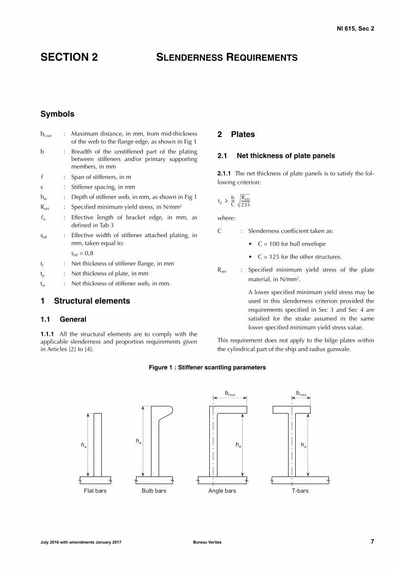
bf-out : Maximum distance, in mm, from mid-thicknessof the web to the flange edge, as shown in Fig 1
b : Breadth of the unstiffened part of the platingbetween stiffeners and/or primary supportingmembers, in mm
: Span of stiffeners, in m
s : Stiffener spacing, in mm
hw : Depth of stiffener web, in mm, as shown in Fig 1
ReH : Specified minimum yield stress, in N/mm2
b : Effective length of bracket edge, in mm, asdefined in Tab 3
seff : Effective width of stiffener attached plating, inmm, taken equal to:
seff = 0,8
tf : Net thickness of stiffener flange, in mm
tp : Net thickness of plate, in mm
tw : Net thickness of stiffener web, in mm.
1 Structural elements
1.1 General
1.1.1 All the structural elements are to comply with theapplicable slenderness and proportion requirements givenin Articles [2] to [4].
2 Plates
2.1 Net thickness of plate panels
2.1.1 The net thickness of plate panels is to satisfy the fol-lowing criterion:
where:
C : Slenderness coefficient taken as:
• C = 100 for hull envelope
• C = 125 for the other structures.
ReH : Specified minimum yield stress of the plate
material, in N/mm2.
A lower specified minimum yield stress may beused in this slenderness criterion provided therequirements specified in Sec 3 and Sec 4 aresatisfied for the strake assumed in the samelower specified minimum yield stress value.
This requirement does not apply to the bilge plates withinthe cylindrical part of the ship and radius gunwale.
Figure 1 : Stiffener scantling parameters
tpbC---- ReH
235----------≥
Bulb bars Angle bars T-barsFlat bars
July 2016 with amendments January 2017 Bureau Veritas 7

NI 615, Sec 2
3 Stiffeners
3.1 Proportions of stiffeners
3.1.1 Net thickness of all stiffener types
The net thickness of stiffeners is to satisfy the following cri-teria:
a) Stiffener web plate:
b) Stiffener flange:
where:
Cw, Cf : Slenderness coefficients given in Tab 1.
Table 1 : Slenderness coefficients Cw and Cf
3.1.2 Net dimensions of angle bars and T-bars
The total flange breadth bf , in mm, for angle bars and T-barsis to satisfy the following criterion:
bf ≥ 0,25 hw
4 Primary supporting members
4.1 Proportions and stiffness
4.1.1 Proportions of web plates and flanges
The net thicknesses (web plate and flange) of primary sup-porting members are to satisfy the following criteria:
a) Web plates:
b) Flanges:
where:
sw : Plate breadth, in mm, taken as the spacing ofthe web stiffeners
Cw : Slenderness coefficient for the web plates takenas:
Cw = 100
Cf : Slenderness coefficient for the flanges taken as:
Cf = 12
4.1.2 Stiffness of deck transverse primary supporting members
The net moment of inertia Ipsm-n50 , in cm4, of deck transverseprimary members supporting deck longitudinals subject toaxial compressive hull girder stress is to comply, within thecentral half of the bending span, with the following crite-rion:
where:
Ipsm-n50 : Net moment of inertia, in cm4, of deck trans-verse primary supporting members with aneffective width of attached plating equal to 0,8 S
bdg : Effective bending span of deck transverse pri-mary supporting members, in m, as defined inthe applicable Rules
S : Spacing of deck transverse primary supportingmembers, in m, as defined in the applicableRules
Ist : Net moment of inertia of deck stiffeners, in cm4,within the central half of the bending span,taken equal to:
Aeff : Net sectional area of the stiffener, including itseffective attached plating seff , in cm2
ReH : Specified minimum yield stress of the materialof the stiffener attached plating, in N/mm2.
4.2 Web stiffeners fitted on primary supporting members
4.2.1 Proportions of web stiffeners
The net thicknesses (web plate and flange) and dimensionsof the web stiffeners fitted on primary supporting membersare to satisfy the requirements specified in [3.1.1] and[3.1.2].
4.2.2 Stiffness of web stiffeners
The net moment of inertia Ist , in cm4, of web stiffeners fittedon primary supporting members, with effective attachedplating seff , is not to be less than the minimum moment ofinertia defined in Tab 2.
Type of stiffeners Cw Cf
Angle bars 75 12
T-bars 75 12
Bulb bars 45 −
Flat bars 22 −
twhw
Cw------- ReH
235----------≥
tfbf-out
Cf------------ ReH
235----------≥
twsw
Cw-------
ReH
235----------≥
tfbf-out
Cf------------ ReH
235----------≥
Ipsm-n50 300 bdg
4
S3s--------- Ist≥
Ist 1 43 , 2 Aeff ReH
235----------=
8 Bureau Veritas July 2016 with amendments January 2017

NI 615, Sec 2
Table 2 : Stiffness criteria for web stiffeners fitted on primary supporting members (PSM)
5 Brackets
5.1 Tripping brackets
5.1.1 Unsupported flange length
The unsupported length of the flange of the primary sup-porting members, in m, i.e. the distance between trippingbrackets, is to satisfy the following criterion:
where:
bf : Flange breadth of primary supporting members,in mm
C : Slenderness coefficient taken as:
• C = 0,022 for symmetrical flanges
• C = 0,033 for asymmetrical flanges
Af-n50 : Net cross-sectional area of the flange, in cm2
Aw-n50 : Net cross-sectional area of the web plate, incm2
ReH : Specified minimum yield stress of the PSMmaterial, in N/mm2
Sb-min : Minimum unsupported flange length, in m,taken as:
• Sb-min = 3,0 m for cargo tank/hold region, ontank/hold boundaries or on hull envelopeincluding external decks
• Sb-min = 4,0 m for the other areas.
5.1.2 Edge stiffening
The tripping brackets on primary supporting members are tobe stiffened by a flange or an edge stiffener if the effectivelength of the edge b , as defined in Tab 3, in mm, is greaterthan 75 tb , where:
tb : Net web thickness of the brackets, in mm.
5.2 End brackets
5.2.1 Proportions
The net web thickness, in mm, of the end brackets sub-jected to compressive stresses is to satisfy the following cri-terion:
where:
db : Bracket depth, in mm, as defined in Tab 3
C : Slenderness coefficient as defined in Tab 3
ReH : Specified minimum yield stress of the endbracket material, in N/mm2.
Stiffener arrangement Minimum moment of inertia of web stiffeners, in cm4
A
Web stiffeners fitted along the PSM span
B
Web stiffeners fitted normal to the PSM span
Note 1: : Length of the web stiffeners, in m:
• for web stiffeners welded to local supporting members, the length is to be measured between the flanges of the local support members
• for sniped web stiffeners, the length is to be measured between the lateral supports, i.e. corresponds to the total dis-tance between the flanges of the primary supporting member, as shown for stiffener arrangement B
Aeff : Net sectional area, in cm2, of the web stiffener, including its effective attached plating seff
tw : Net web thickness of the primary supporting member, in mmReH : Specified minimum yield stress of the material of the web plate of the primary supporting member, in N/mm2.
Ist 0 72 2 Aeff ReH
235----------,≥
Ist 1 14 s2 tw 2 5 1000s
----------------, 2 s1000----------------–
ReH
235---------- 10 5–,≥
Sb Max ≤ bf CAf-n50
Af-n50Aw-n50
3---------------+
----------------------------------------- 235
ReH---------- ; Sb-min
tbdb
C----- ReH
235----------≥
July 2016 with amendments January 2017 Bureau Veritas 9

NI 615, Sec 2
Table 3 : Slenderness coefficient C for proportions of brackets
5.3 Edge reinforcement
5.3.1 Reinforcement of bracket edges
The web depth hw , in mm, of the edge stiffeners in way ofbrackets is to satisfy the following criterion:
where:
C : Slenderness coefficient, taken as:
• C = 75 for end brackets
• C = 50 for tripping brackets
ReH : Specified minimum yield stress of the stiffenermaterial, in N/mm2.
5.3.2 Proportions of edge stiffeners
The net thicknesses (web plate and flange) and dimensionsof the edge stiffeners are to satisfy the requirements speci-fied in [3.1.1] and [3.1.2].
6 Other structures
6.1 Pillars
6.1.1 Proportions of I-section pillars
The net thicknesses (web plate and flanges) and dimensionsof I-section pillars are to comply with the requirementsspecified in [3.1.1] and [3.1.2].
6.1.2 Proportions of box section pillars
The net thickness of thin-walled box section pillars is tocomply with the requirements specified in [3.1.1], item a).
Mode C
Brackets without edge stiffener
with:
Brackets with edge stiffener
C = 70
b
db
C 20 db
b----- 16+=
0 25, db
b----- 1 0,≤ ≤
db
hw Max Cb ReH
235---------- ; 50
≥
10 Bureau Veritas July 2016 with amendments January 2017

NI 615, Sec 2
6.1.3 Proportions of circular section pillarsThe net thickness t, in mm, of circular section pillars is tocomply with the following criterion:
where:r : Mid-thickness radius of the circular section, in
mm.
6.2 Edge reinforcement in way of openings
6.2.1 Depth of edge stiffenersWhen fitted as shown in Fig 2, the web depth hw , in mm, ofedge stiffeners in way of openings is to satisfy the followingcriterion:
where:
C : Slenderness coefficient taken as:
C = 50
ReH : Specified minimum yield stress of the edge stiff-ener material, in N/mm2.
6.2.2 Proportions of edge stiffeners
The net thicknesses (web plate and flange) and dimensionsof the edge stiffeners are to satisfy the requirements speci-fied in [3.1.1] and [3.1.2].
Figure 2 : Typical edge reinforcements
t r50------≥
hw Max C ReH
235---------- ; 50
≥
July 2016 with amendments January 2017 Bureau Veritas 11

NI 615, Sec 3
SECTION 3 PRESCRIPTIVE BUCKLING REQUIREMENTS
Symbols
ηall : Allowable buckling utilisation factor, as definedin Sec 1, [2.3]
EPP : Elementary Plate Panel, i.e. the unstiffened partof the plating between stiffeners and/or primarysupporting members
LCP : Load Calculation Point, as defined in the appli-cable Rules.
1 General
1.1 Scope
1.1.1 This Section applies to plate panels, including curvedplate panels, and stiffeners subject to hull girder compres-sion and shear stresses. In addition the following structuralmembers subject to compressive stresses are to be checked:• corrugations of transverse vertically corrugated bulk-
heads• corrugations of longitudinal corrugated bulkheads• struts• pillars• cross ties.
1.1.2 The hull girder buckling strength requirements applyalong the full length of the ship.
1.1.3 Design load setsThe buckling checks are to be performed for all design loadsets, with pressure combination defined in the applicableRules.
For each design load set, and for all dynamic load cases, thelateral pressure is to be determined and applied at a loadcalculation point as described in the applicable Rules. It isto be applied together with the hull girder stress combina-tions given in [2.1].
1.2 Equivalent plate panel
1.2.1 In longitudinal stiffening arrangement, when the plate
thickness varies over the width b of a plate panel, the buck-ling check is to be performed for an equivalent plate panelwidth, combined with the smaller plate thickness t1. The
width beq of this equivalent plate panel, in mm, is defined
by the following formula:
where:
1 : Width of the part of the plate panel with the
smaller net plate thickness t1, in mm, as defined
in Fig 1
2 : Width of the part of the plate panel with the
greater net plate thickness t2, in mm, as defined
in Fig 1.
1.2.2 In transverse stiffening arrangement, when an EPP ismade with different thicknesses, the buckling check of theplate and stiffeners is to be made for each thickness consid-ered constant on the EPP, the stresses and pressures beingestimated for the EPP at the LCP.
1.2.3 Materials
When the plate panel is made of different materials, theminimum yield strength is to be used for the bucklingassessment.
Figure 1 : Plate thickness change over the width b
beq 1 2 t1
t2
---
1 5,
+=
12 Bureau Veritas July 2016 with amendments January 2017
NI 615, Sec 3
2 Hull girder stress
2.1 General
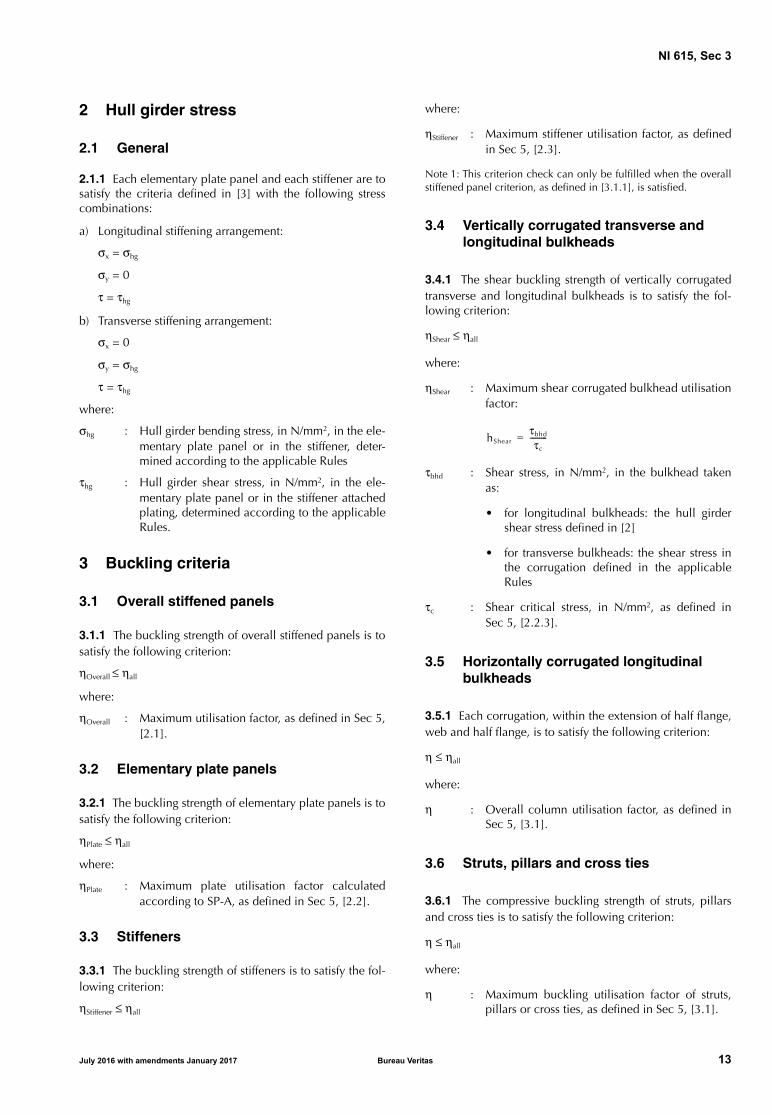
2.1.1 Each elementary plate panel and each stiffener are tosatisfy the criteria defined in [3] with the following stresscombinations:
a) Longitudinal stiffening arrangement:
σx = σhg
σy = 0
τ = τhg
b) Transverse stiffening arrangement:
σx = 0
σy = σhg
τ = τhg
where:
σhg : Hull girder bending stress, in N/mm2, in the ele-mentary plate panel or in the stiffener, deter-mined according to the applicable Rules
τhg : Hull girder shear stress, in N/mm2, in the ele-mentary plate panel or in the stiffener attachedplating, determined according to the applicableRules.
3 Buckling criteria
3.1 Overall stiffened panels
3.1.1 The buckling strength of overall stiffened panels is tosatisfy the following criterion:
ηOverall ≤ ηall
where:
ηOverall : Maximum utilisation factor, as defined in Sec 5,[2.1].
3.2 Elementary plate panels
3.2.1 The buckling strength of elementary plate panels is tosatisfy the following criterion:
ηPlate ≤ ηall
where:
ηPlate : Maximum plate utilisation factor calculatedaccording to SP-A, as defined in Sec 5, [2.2].
3.3 Stiffeners
3.3.1 The buckling strength of stiffeners is to satisfy the fol-lowing criterion:
ηStiffener ≤ ηall
where:
ηStiffener : Maximum stiffener utilisation factor, as definedin Sec 5, [2.3].
Note 1: This criterion check can only be fulfilled when the overallstiffened panel criterion, as defined in [3.1.1], is satisfied.
3.4 Vertically corrugated transverse and longitudinal bulkheads
3.4.1 The shear buckling strength of vertically corrugatedtransverse and longitudinal bulkheads is to satisfy the fol-lowing criterion:
ηShear ≤ ηall
where:
ηShear : Maximum shear corrugated bulkhead utilisationfactor:
τbhd : Shear stress, in N/mm2, in the bulkhead takenas:
• for longitudinal bulkheads: the hull girdershear stress defined in [2]
• for transverse bulkheads: the shear stress inthe corrugation defined in the applicableRules
τc : Shear critical stress, in N/mm2, as defined inSec 5, [2.2.3].
3.5 Horizontally corrugated longitudinal bulkheads
3.5.1 Each corrugation, within the extension of half flange,web and half flange, is to satisfy the following criterion:
η ≤ ηall
where:
η : Overall column utilisation factor, as defined inSec 5, [3.1].
3.6 Struts, pillars and cross ties
3.6.1 The compressive buckling strength of struts, pillarsand cross ties is to satisfy the following criterion:
η ≤ ηall
where:
η : Maximum buckling utilisation factor of struts,pillars or cross ties, as defined in Sec 5, [3.1].
hShearτbhd
τc
---------=
July 2016 with amendments January 2017 Bureau Veritas 13

NI 615, Sec 4
SECTION 4 BUCKLING REQUIREMENTS FOR DIRECT STRENGTH ANALYSIS
Symbols
ηall : Allowable buckling utilisation factor, as definedin Sec 1, [2.3]
α : Aspect ratio of the plate panel, defined in Sec 5.
1 General
1.1 Scope
1.1.1 The requirements of this Section apply for the buck-ling assessment of direct strength analysis subjected to com-pressive stress, shear stress and lateral pressure.
1.1.2 All structural elements in the FE analysis are to beassessed individually. The buckling checks are to be per-formed for the following structural elements:
• stiffened and unstiffened panels, including curved panels
• web plates in way of openings
• corrugated bulkheads
• struts, pillars and cross ties.
2 Stiffened and unstiffened panels
2.1 General
2.1.1 The plate panels of hull structure are to be modelledas stiffened or unstiffened panels. Method A or Method B asdefined in Sec 1, [2] is to be used according to App 2.
2.1.2 Average thickness of plate panel
Where the plate thickness along a plate panel is not con-stant, the panel used for the buckling assessment is to bemodelled according to the applicable Rules, with aweighted average thickness tavr , in mm, taken as:
where:
Ai : Area of the i-th plate element, in mm2
ti : Net thickness of the i-th plate element, in mm
n : Number of finite elements defining the bucklingplate panel.
2.1.3 Yield stress of plate panelThe yield stress ReH_P , in N/mm2, of a plate panel is taken asthe minimum value of the specified yield stresses of the ele-ments within the plate panel.
2.2 Stiffened panels
2.2.1 To represent the overall buckling behaviour, eachstiffener with attached plating is to be modelled as a stiff-ened panel of the extent defined in App 2, Tab 1.
2.2.2 If the stiffener properties or the stiffener spacing varywithin the stiffened panel, the calculations are to be per-formed separately for all the configurations of the plate pan-els, i.e. for each stiffener and plate between the stiffeners.The plate thickness, stiffener properties and stiffener spacingat the considered location are to be assumed for the wholepanel.
2.3 Unstiffened panels
2.3.1 Irregular panelIn way of web frames, stringers and brackets, the geometryof the panel (i.e. plate bounded by web stiffeners/faceplates) may not have a rectangular shape. In this case, anequivalent rectangular panel is to be defined according to[2.3.2] for irregular geometry and [2.3.3] for triangulargeometry and is to comply with buckling assessment.
2.3.2 Modelling of an unstiffened panel with irregular geometry
Unstiffened panels with irregular geometry are to be ideal-ised to equivalent rectangular panels for plate bucklingassessment according to the following procedure:
a) The four corners closest to a right angle (90 deg) in thebounding polygon for the plate are identified as shownin Fig 1.
Figure 1 : Unstiffened panel
b) The distances along the plate bounding polygonbetween the corners (as shown in Fig 2) are calculated,i.e. the sum of all the straight line segments between theend points.
tavr
Ai
1
n
ti
Ai
1
n
----------------=
14 Bureau Veritas July 2016 with amendments January 2017

NI 615, Sec 4
Figure 2 : Distances
c) The pair of opposite edges with the smallest total lengthis identified, i.e. the minimum of (d1 + d3) and (d2 + d4)
d) A line joins the middle points of the chosen oppositeedges as shown in Fig 3 (a middle point is defined as thepoint at half the distance from one end). This linedefines the longitudinal direction for the capacitymodel. The length of the line defines the length a of thecapacity model, measured from one end point.
Figure 3 : Join line a
e) The length b of the shorter side, in mm, as shown in Fig 4,is to be taken as:
b = A/a
where:
Figure 4 : Side b
A : Area of the plate, in mm²
a : Length, in mm, defined in item d).
f) The stresses from the direct strength analysis are to betransformed into the local coordinate system of theequivalent rectangular panel. These stresses are to beused for the buckling assessment.
2.3.3 Modelling of an unstiffened panel with triangular geometry
Unstiffened panels with triangular geometry are to be ideal-ised to equivalent rectangular panels for plate bucklingassessment according to the following procedure:
a) Medians are constructed as shown in Fig 5.
Figure 5 : Medians
b) The longest median is identified as shown in Fig 6. Thismedian, the length of which is 1 in mm, defines the lon-gitudinal direction for the capacity model.
Figure 6 : Longest median 1
c) The width 2 of the model, in mm, as shown in Fig 7, isto be taken as:
2 = A/1
where:
A : Area of the plate, in mm².
Figure 7 : Width 2 of the model
d) The lengths of the shorter side b and the longer side a, inmm, of the equivalent rectangular panel are to be takenas:
a = 1 Ctri
where:
e) The stresses from the direct strength analysis are to betransformed into the local coordinate system of theequivalent rectangular panel. These stresses are to beused for the buckling assessment.
2.4 Reference stresses
2.4.1 The stress distribution is to be taken from the directstrength analysis and applied to the buckling model.
2.4.2 The reference stresses are to be calculated using thestress based reference stresses, as defined in App 1.
2.5 Lateral pressure
2.5.1 The lateral pressure applied to the direct strengthanalysis is also to be applied to the buckling assessmentunless otherwise stated in the applicable Rules.
1
12
b2
Ctri
-------=
Ctri 0 42
1
----, 0 6,+=
July 2016 with amendments January 2017 Bureau Veritas 15

NI 615, Sec 4
2.5.2 Where the lateral pressure is not constant over abuckling panel defined by a number of finite plate ele-ments, an average lateral pressure Pavr , in N/mm2, is calcu-lated using the following formula:
where:
Ai : Area of the i-th plate element, in mm2
Pi : Lateral pressure of the i-th plate element, inN/mm2
n : Number of finite elements in the bucklingpanel.
2.6 Buckling criteria
2.6.1 UP-AThe compressive buckling strength of UP-A is to satisfy thefollowing criterion:
ηUP-A ≤ ηall
where:
ηUP-A : Maximum plate panel utilisation factor calcu-lated according to Method A, as defined in Sec5, [2.2].
2.6.2 UP-BThe compressive buckling strength of UP-B is to satisfy thefollowing criterion:
ηUP-B ≤ ηall
where:
ηUP-B : Maximum plate panel utilisation factor calcu-lated according to Method B, as defined in Sec5, [2.2].
2.6.3 SP-AThe compressive buckling strength of SP-A is to satisfy thefollowing criterion:
ηSP-A ≤ ηall
where:
ηSP-A : Maximum stiffened panel utilisation factortaken as the maximum of:
• the overall stiffened panel capacity, asdefined in Sec 5, [2.1]
• the plate capacity calculated according toMethod A, as defined in Sec 5, [2.2]
• the stiffener buckling strength as defined inSec 5, [2.3], considering separately theproperties (thickness, dimensions), the pres-sures defined in [2.5.2] and the referencestresses of each EPP at both sides of the stiff-ener.
Note 1: The stiffener buckling capacity check can only be fulfilledwhen the overall stiffened panel capacity, as defined in Sec 5, [2.1],is satisfied.
2.6.4 SP-BThe compressive buckling strength of SP-B is to satisfy thefollowing criterion:
ηSP-B ≤ ηall
where:
ηSP-B : Maximum stiffened panel utilisation factortaken as the maximum of:
• the overall stiffened panel capacity, asdefined in Sec 5, [2.1]
• the plate capacity calculated according toMethod B, as defined in Sec 5, [2.2]
• the stiffener buckling strength as defined inSec 5, [2.3], considering separately theproperties (thickness, dimensions), the pres-sures defined in [2.5.2] and the referencestresses of each EPP at both sides of the stiff-ener.
Note 1: The stiffener buckling capacity check can only be fulfilledwhen the overall stiffened panel capacity, as defined in Sec 5, [2.1],is satisfied.
2.6.5 Web plate in way of openingsThe web plate of primary supporting members in way ofopenings is to satisfy the following criterion:
ηopening ≤ ηall
where:
ηopening : Maximum web plate utilisation factor in way ofopenings, as defined in Sec 5, [2.4].
3 Corrugated bulkheads
3.1 General
3.1.1 Three buckling failure modes are to be assessed oncorrugated bulkheads:
• corrugation overall column buckling
• corrugation flange panel buckling
• corrugation web panel buckling.
3.2 Reference stresses
3.2.1 Each corrugation flange and web panel is to beassessed.
3.2.2 The membrane stresses at element centroid are to beused.
3.2.3 For the application of this requirement:
b : Width of the considered member (flange orweb) of the corrugation.
The maximum normal stress σx parallel to the corrugation isthe maximum of the two following stresses:
• the normal stress parallel to the corrugation taken at b/2from the corrugation ends
• the normal stress parallel to the corrugation within themid-span of the corrugation.
Pavr
Ai
1
n
Pi
Ai
1
n
-----------------=
16 Bureau Veritas July 2016 with amendments January 2017

NI 615, Sec 4
Figure 8 : Single corrugation
When a corrugation end is fitted with a shedder plate, thenormal stress parallel to the corrugation at this end is to betaken at b/2 from the intersection of the shedder plate withthe point at mid-breadth of the flange or of the web, as thecase may be.
The maximum shear stress is the shear stress which is maxi-mum at the corrugation flange or web at the point b/2 fromends as defined above for the normal stress parallel to thecorrugation.
The in-plane stresses σx and σy and the shear stress τ are tobe taken as the element stresses averaged over the width ofthe considered member (flange or web) at the consideredlocation.
When the stress value at b/2 from ends cannot be obtaineddirectly from FEA element, the stress at this location is to beobtained by interpolation. This interpolation is to be madeon elements extending over a distance equal to 3 b at apoint located at b/2 from the end of the corrugation or fromthe intersection of the shedder plate if fitted, measured atmid-breadth of the flange or of the web. The interpolationof the in-plane stresses σx and σy is to be made in accord-ance with App 1, [2.1].
The shear stress at b/2 is obtained by linear interpolationbetween the elements the closest to b/2 location.
3.2.4 Where more than one plate thickness is used for aflange panel, the maximum stress is to be obtained for eachthickness range and is to be checked with the buckling cri-teria for each thickness.
3.3 Overall column buckling
3.3.1 The overall buckling failure mode of corrugated bulk-heads subjected to axial compression is to be checked forcolumn buckling (e.g. horizontally corrugated bulkheadsand vertically corrugated bulkheads subjected to local verti-cal forces).
Table 1 : Application of overall column buckling for corrugated bulkheads
3.3.2 Each corrugation unit, i.e. each single corrugationmade up of half flange/web/half flange, as shown in grey inFig 8, is to satisfy the following criterion:
ηOverall ≤ ηall
where:
ηOverall : Maximum overall column utilisation factor, asdefined in Sec 5, [3.1] and Sec 5, [3.1.2], con-sidering the corrugation unit as a pillar with anunsupported length equal to the length of thecorrugation.
3.3.3 End constraint factor fend to be applied correspondsto:
• pinned ends, in general
• fixed end support, in case of stool having a widthexceeding 2 times the depth of the corrugation.
3.4 Local buckling
3.4.1 The compressive buckling strength of a unit flangeand a unit web of corrugated bulkheads is to satisfy the fol-lowing criterion:
ηCorr ≤ ηall
where:
ηCorr : Maximum unit flange or unit web utilisationfactor, as defined in Sec 5, [3.2.1].
Two stress combinations are to be considered for the appli-cation of this criterion:
• the maximum normal stress σx parallel to the corruga-tion, combined with the stress σy perpendicular to thecorrugation and with the shear stress τ, at the locationwhere the maximum normal stress parallel to the corru-gation occurs.
• the maximum shear stress τ, combined with the normalstress σx parallel to the corrugation and with the stress σy
perpendicular to the corrugation, at the location wherethe maximum shear stress occurs.
The buckling assessment is to be performed with an aspectratio α equal to 2, and for the member thicknesses wherethe maximum compressive/shear stress occurs (see [3.2.4]).
Bulkhead orientation
Corrugation orientation
Horizontal Vertical
LongitudinalorTransverse
Required Required, when sub-jected to local vertical forces (e.g. crane loads)
July 2016 with amendments January 2017 Bureau Veritas 17

NI 615, Sec 4
4 Struts, pillars and cross ties
4.1 Buckling criteria
4.1.1 The compressive buckling strength of struts, pillarsand cross ties is to satisfy the following criterion:
ηPillar ≤ ηall
where:ηPillar : Maximum utilisation factor of struts, pillars or
cross ties, as defined in Sec 5, [3.1].
18 Bureau Veritas July 2016 with amendments January 2017

NI 615, Sec 5
SECTION 5 BUCKLING CAPACITY
Symbols
As : Net sectional area of the stiffener withoutattached plating, in mm2
a : Length of the longer side of the plate panel, inmm
b : Length of the shorter side of the plate panel, inmm
beff : Effective width of the attached plating of a stiff-ener, in mm, as defined in [2.3.5]
beff1 : Effective width of the attached plating of a stiff-ener, in mm, without the shear lag effect, takenas:
• when σx > 0
- for prescriptive assessment:
- for FE analysis:
beff1 = Cx b
• when σx ≤ 0
beff1 = b
bf : Breadth of the stiffener flange, in mm
b1, b2 : Width of the plate panel on each side of theconsidered stiffener, in mm
Cx1, Cx2 : Tab 4, calculated for the EPP1 and EPP2 oneach side of the considered stiffener accordingto case 1
Cx : Reduction factor as defined in [2.2.3]
d : Length, in mm, of the side parallel to the axis ofthe cylinder corresponding to the curved platepanel, as shown in Tab 5
E : Young’s modulus of the material, in N/mm2
ef : Distance, in mm, from the attached plating tothe flange centre, as shown in Fig 1, dependingon the profile type:
• ef = hw for flat bars
• ef = hw – 0,5 tf for bulb bars
• ef = hw + 0,5 tf for angle bars and T-bars
Flong : Correction factor defined in [2.2.4]
hw : Depth of the stiffener web, in mm, as shown inFig 1
: Span of the stiffener, in mm, equal to the spac-ing between the primary supporting members
R : Radius of the curved plate panel, in mm
ReH_P : Specified minimum yield stress of the plate, inN/mm2
ReH_S : Specified minimum yield stress of the stiffener,in N/mm2
S : Partial safety factor, to be taken as:
• for structures exposed to local concentratedloads:
S = 1,1
• for all the other cases:
S = 1,0
tp : Net thickness of the plate panel, in mm
tw : Net thickness of the stiffener web, in mm
tf : Net thickness of the stiffener flange, in mm
x axis : For a rectangular buckling panel, local axis par-allel to its long edge
y axis : For a rectangular buckling panel, local axis per-pendicular to its long edge
α : Aspect ratio of the plate panel, to be taken as:
β : Coefficient taken as:
ω : Coefficient taken as:
ω = Min (3 ; α)
σx : Stress applied on the edge along x axis of thebuckling panel, in N/mm2
σy : Stress applied on the edge along y axis of thebuckling panel, in N/mm2
σ1 : Maximum stress, in N/mm2
σ2 : Minimum stress, in N/mm2
σE : Elastic buckling reference stress, in N/mm2, tobe taken as:
• for the application of plate limit stateaccording to [2.2.1]:
• for the application of curved plate panelsaccording to [2.2.5]:
beff1Cx1b1 Cx2b2+
2----------------------------------=
α ab---=
β 1 ψ–α
-------------=
σEπ2 E
12 1 ν2–( )-------------------------- tp
b---
2
=
σEπ2 E
12 1 ν2–( )-------------------------- tp
d---
2
=
July 2016 with amendments January 2017 Bureau Veritas 19

NI 615, Sec 5
τ : Applied shear stress, in N/mm2
ν : Poisson’s ratio of the material
ψ : Edge stress ratio, to be taken as:
γ : Stress multiplier factor acting on loads. When γis such that the loads reach the interaction for-mulae, then:
γ = γc
γc : Stress multiplier factor at failure.
1 General
1.1 Scope
1.1.1 This Section contains the methods for determinationof the buckling capacity of plate panels, stiffeners, primarysupporting members, struts, pillars, cross ties and corru-gated bulkheads.
1.1.2 For the application of this Section, the stresses σx , σy
and τ applied on the structural members are defined in:
• Sec 3 for the prescriptive requirements
• Sec 4 for the FE analysis requirements.
1.1.3 Ultimate buckling capacity
The ultimate buckling capacity is calculated by applying theactual stress combination and then increasing or decreasingthe stresses proportionally until the interaction formulaedefined in [2.1.1], [2.2.1], and [2.3.4] are equal to 1,0.
1.1.4 Buckling utilisation factor
The buckling utilisation factor η of the structural member isequal to the highest utilisation factor obtained for the differ-ent buckling modes.
1.1.5 Lateral pressure
The lateral pressure is to be considered as constant in thebuckling strength assessment.
2 Buckling capacity of plates and stiffeners
2.1 Overall stiffened panel capacity
2.1.1 The elastic stiffened panel limit state is based on thefollowing interaction formula:
where cf and Pz are defined in [2.3.4].
2.2 Plate capacity
2.2.1 Plate limit statea) The plate limit state is based on the following interac-
tion formulae:
•
with:
• when σx ≥ 0:
• when σy ≥ 0:
•
where:σx , σy : Normal stresses applied on the plate panel,
in N/mm2, to be taken as defined in [2.2.6]τ : Shear stress applied on the plate panel, in
N/mm2
σcx’ : Ultimate buckling stress, in N/mm2, in thedirection parallel to the longer edge of thebuckling panel, as defined in [2.2.3]
σcy’ : Ultimate buckling stress, in N/mm2, in thedirection parallel to the shorter edge of thebuckling panel, as defined in [2.2.3]
Figure 1 : Stiffener cross-sections
ψ σ2
σ1
-----=
Pz
cf
----- 1=
γc1 σx S
σcx′
--------------------
e0 γc1 σy S
σcy′
--------------------
e0 γc1 τ S
τc′
--------------------
e0
Ω–+ + 1=
Ω Bγc1 σx S
σcx′
--------------------
e0 2⁄ γc1 σy S
σcy′
--------------------
e0 2⁄
=
γc2 σx S
σcx′
--------------------
2 βp0.25⁄ γc2 τ S
τc′
--------------------
2 βp0.25⁄
+ 1=
γc3 σy S
σcy′
--------------------
2 βp0.25⁄ γc3 τ S
τc′
--------------------
2 βp0.25⁄
+ 1=
γc4 τ S
τc′
-------------------- 1=
20 Bureau Veritas July 2016 with amendments January 2017

NI 615, Sec 5
τc’ : Ultimate buckling shear stresses, in N/mm2,as defined in [2.2.3]
γc1 , γc2 , γc3 , γc4 : Stress multiplier factors at failure for
each of the above different limit states.
γc2 and γc3 are to be considered only whenσx ≥ 0 and σy ≥ 0, respectively
B, e0 : Coefficients given in Tab 1.
b) The stress multiplier factor at failure, γc , is taken as:
γc = Min (γc1 ; γc2 ; γc3 ; γc4)
Table 1 : Coefficients B and e0
2.2.2 Reference degree of slenderness
The reference degree of slenderness is to be taken as:
where:
K : Buckling factor, as defined in Tab 4 for planeplate panels and Tab 5 for curved plate panels.
2.2.3 Ultimate buckling stresses
The ultimate buckling stresses of plate panels, in N/mm2,are to be taken as:
σcx’ = Cx ReH_P
σcy’ = Cy ReH_P
The ultimate buckling stress of plate panels subject to shear,in N/mm2, is to be taken as:
where:
Cx , Cy , Cτ : Reduction factors, as defined in Tab 4.
• for the first equation of [2.2.1]:
when σx < 0 or σy < 0, the reduction factorsare to be taken as follows:
Cx = Cy = Cτ = 1
• in the other cases:
Cy is calculated according to Tab 4, usingthe values of c1 given in Tab 2.
Table 2 : Coefficient c1
The boundary conditions for the plates are to be consideredas simply supported: see case 1, case 2 and case 15 of Tab 4.
If the boundary conditions differ significantly from the con-dition ‘simple support’, a more appropriate boundary con-dition can be applied, chosen from the different cases ofTab 4, subject to the agreement of the Society.
2.2.4 Correction factor Flong
The correction factor Flong depending on the edge stiffenertypes on the longer side of the buckling panel is defined inTab 3. An average value of Flong is to be used for the platepanels having different edge stiffeners. For stiffener typesother than those mentioned in Tab 3, the value of c is to beagreed by the Society. In such a case, a value of c higherthan those mentioned in Tab 3 can be used, provided it isverified by buckling strength check of panel using non-linear FEA and deemed appropriate by the Society.
Table 3 : Correction factor Flong
Applied stresses B e0
σx ≥ 0 and σy ≥ 0 0,7 − 0,3 βp / α2
σx < 0 or σy < 0 1,0 2,0
Note 1:βp : Plate slenderness parameter taken as:
2 βp0 25,⁄
βpbtp
--- ReH_P
E------------=
λ ReH_P
KσE
------------=
τc ′ Cτ ReH_P
3------------=
Plate panels c1
SP-A
UP-A
Vertically stiffened single side skin of bulk carrier
Corrugations of corrugated bulkhead
SP-Bc1 = 1
UP-B
c1 1 1α---–
0≥=
Structural element types Flong
Unstiffened panel 1,0
Stiffened panel
Stiffener not fixed at both ends 1,0
Stiffener fixed at both ends
Flat bar (1) (c = 0,10)
Bulb bar (c = 0,30)
Angle bar (c = 0,40)
T-bar (c = 0,30)
Girder of high rigidity (e.g. bottom transverse) 1,4
(1) tw is the net web thickness, in mm, without the correction defined in [2.3.2].
Flong c 1+= for tw
tp---- 1>
Flong ctw
tp
----
3
1+= for tw
tp
---- 1≤
July 2016 with amendments January 2017 Bureau Veritas 21

NI 615, Sec 5
2.2.5 Curved plate panelsThis requirement for curved plate limit state is applicablewhen R/tp ≤ 2500. Otherwise, the requirement for platelimit state given in [2.2.1] is applicable.
The curved plate limit state is based on the following inter-action formula:
with:
where:σax : Axial stress applied to the cylinder correspond-
ing to the curved plate panel, in N/mm2.
In case of tensile axial stresses: σax = 0
σtg : Tangential stress applied to the cylinder corre-
sponding to the curved plate panel, in N/mm2.
In case of tensile tangential stresses: σtg = 0
Cax , Ctg , Cτ : Buckling reduction factors of the curved platepanel, as defined in Tab 5.
The stress multiplier factor γc of the curved plate panel neednot be taken less than the stress multiplier factor γc obtainedfrom [2.2.1] for an expanded plane panel.
2.2.6 Normal stresses applied to plate panel
The normal stresses σx and σy, in N/mm2, to be applied forthe plate panel capacity calculation as given in [2.2.1], areto be taken as follows:
• for FE analysis, the reference stresses as defined in Sec 4,[2.4]
• for prescriptive assessment, the axial or transverse com-pressive stresses at load calculation points of the consid-ered elementary plate panel, as defined in theapplicable Rules
• for grillage analysis where the stresses are obtainedbased on the beam theory, the following values:
where:
σxb , σyb : Stresses, in N/mm2, from grillage beam anal-ysis, respectively along x axis and y axis ofthe attached buckling panel.
Table 4 : Buckling factor K and reduction factor C for plane plate panels
γcσaxSCaxReH_P
---------------------
1 25, γcσtgSCtgReH_P
--------------------
1 25, γcτ 3SCτReH_P
-------------------
2
ϒ–+ + 1=
ϒ 0 5γcσaxS
CaxReH_P
--------------------- γcσtgS
CtgReH_P
-------------------- ,=
σxσxb νσyb+
1 ν2–-------------------------=
σyσyb νσxb+
1 ν2–-------------------------=
Case Stress ratio ψ Buckling factor K Reduction factor C
Case 1
1 ≥ ψ ≥ 0
• when σx ≤ 0:
Cx = 1,00
• when σx > 0:
Cx = 1,00 for λ ≤ λc
where:
0 > ψ > −1 Kx = Flong [7,63 − ψ (6,26 − 10 ψ)]
ψ ≤ −1 Kx = Flong [5,975 (1 − ψ)2]
Case 2
1 ≥ ψ ≥ 0• when α ≤ 6:
• when α > 6:
Kx Flong8 4,
ψ 1 1,+--------------------=
Cx c 1λ--- 0 22,
λ2-------------–
= for λ λc>
c 1 25, 0 12ψ,–( ) 1 25,≤=
λcc2--- 1 1 0 88,
c-------------–+
=
Ky
2 1 1α2-----+
2
1 ψ 1 ψ–( )100---------------- 2 4,
α2--------- 6 9f1,+ + +
------------------------------------------------------------------------=
f1 1 ψ–( ) α 1–( )=
f1 0 6 1 6ψα-------–
α 14α------+
with f1 14 5, 0 35,α2-------------–≤
,=
22 Bureau Veritas July 2016 with amendments January 2017

NI 615, Sec 5
Case 2 (continued) • when σy ≤ 0: Cy = 1,00
• when σy > 0:
where:
c = (1,25 − 0,12 Ψ) ≤ 1,25
R = 0,22 for λ ≥ λc
c1 as defined in Tab 2
• when α > 6 (1 − Ψ):
with f1 ≤ 14,5 − 0,35 β2
f2 = f3 = 0
• when 3 (1 − Ψ) ≤ α ≤ 6 (1 − Ψ):
f2 = f3 = 0
• when 1,5 (1 − Ψ) ≤ α < 3 (1 − Ψ):
f2 = f3 = 0
• when 1 − Ψ ≤ α < 1,5 (1 − Ψ):
- for α > 1,5:
f2 = 3 β − 2
f3 = 0
- for α ≤ 1,5:
f3 = 0
f4 = [1,5 − Min (1,5 ; α)]2
• when 0,75 (1 − Ψ) ≤ α < 1 − Ψ:
f1 = 0
f4 = [1,5 − Min(1,5 ; α)]2
with:
Case Stress ratio ψ Buckling factor K Reduction factor C
0 ψ 1 4α3-------–≥>
Ky200 1 β2+( )2
1 f3–( ) 100 2 4β2, 6 9f1, 23f2+ + +( )---------------------------------------------------------------------------------------------=
Cy c 1λ--- R F2 H R–( )+
λ2-------------------------------------–=
R λ 1 λc---–
= for λ λc<
λcc2--- 1 1 0 88,
c-------------–+
=
F 1
K0 91,------------- 1–
λp2
-----------------------------– c1 0≥=
λp2 λ2 0 5,–= for 1 λp
2 3≤ ≤
H λ 2λ
c T T2 4–+( )--------------------------------------- R≥–=
T λ 1415λ---------- 1
3---+ +=
f1 0 6 1β--- 14β+ ,=
f11β--- 1–=
f11β--- 2 ωβ–( )4– 9 ωβ 1–( ) 2
3--- β– –=
f1 2 1β--- 16 1 ω
3----–
4
– 1β--- 1– =
f1 2 1 5,1 ψ–------------- 1– 1
β--- 1– =
f2ψ 1 16f4
2–( )1 α–
----------------------------- =
f2 1 2 31 β 1–( ), 48 43--- β– f4
2–+=
f3 3f4 β 1–( ) f4
1 81,------------- α 1–
1 31,-------------–
=
ψ 1 4α3-------–<
Ky 5 972 β2
1 f3–-------------,=
f3 f5f5
1 81,------------- 1 3ψ+
5 24,-----------------+
=
f59
16------ 1 Max 1 ψ;–( )+[ ]2=
July 2016 with amendments January 2017 Bureau Veritas 23

NI 615, Sec 5
Case 3
1 ≥ ψ ≥ 0
0 > ψ ≥ −1
Case 4
1 ≥ ψ ≥ −1
Case 5
−
• when α ≥ 1,64:Kx = 1,28
• when α < 1,64:
Case 61 ≥ ψ ≥ 0
0 > ψ ≥ −1
Case 7
1 ≥ ψ ≥ −1
Case 8
−
Case 9
− Kx = 6,97
Cx = 1,00 for λ ≤ 0,83
Case 10
−
Cy = 1,00 for λ ≤ 0,83
Case 11
−
• when α ≥ 4:Kx = 4
• when α < 4:
Cx = 1,00 for λ ≤ 0,83
Case Stress ratio ψ Buckling factor K Reduction factor C
Kx
4 0 425, 1α2-----+
3ψ 1+----------------------------------------=
Cx 1 00,= for λ 0 7,≤
Cx1
λ2 0 51,+------------------------= for λ 0 7,>
Kx 4 0 425, 1α2-----+
1 ψ+( )
5ψ 1 3 42ψ,–( )–
=
Kx 0 425, 1α2-----+
3 ψ–2
-------------=
Kx1α2----- 0 56, 0 13α2,+ +=
Ky4 0 425, α2+( )
3ψ 1+( )α2-------------------------------------=
Cy 1 00,= for λ 0 7,≤
Cy1
λ2 0 51,+------------------------= for λ 0 7,>
Ky 4 0 425, α2+( ) 1 ψ+( ) 1α2-----=
5ψ 1 3 42ψ,( )–[ ] 1α2-----–
Ky 0 425, α2+( ) 3 ψ–( )2α2------------------=
Ky 1 0 56,α2------------- 0 13,
α4-------------+ +=
Cx 1 13 1λ--- 0 22,
λ2-------------–
,= for λ 0 83,>
Ky 4 2 07,α2------------- 0 67,
α4-------------+ +=
Cy 1 13 1λ--- 0 22,
λ2-------------–
,= for λ 0 83,>
Kx 4 2 74 4 α–3
------------- ,
4
+=Cx 1 13 1
λ--- 0 22,
λ2-------------–
,= for λ 0 83,>
24 Bureau Veritas July 2016 with amendments January 2017
NI 615, Sec 5
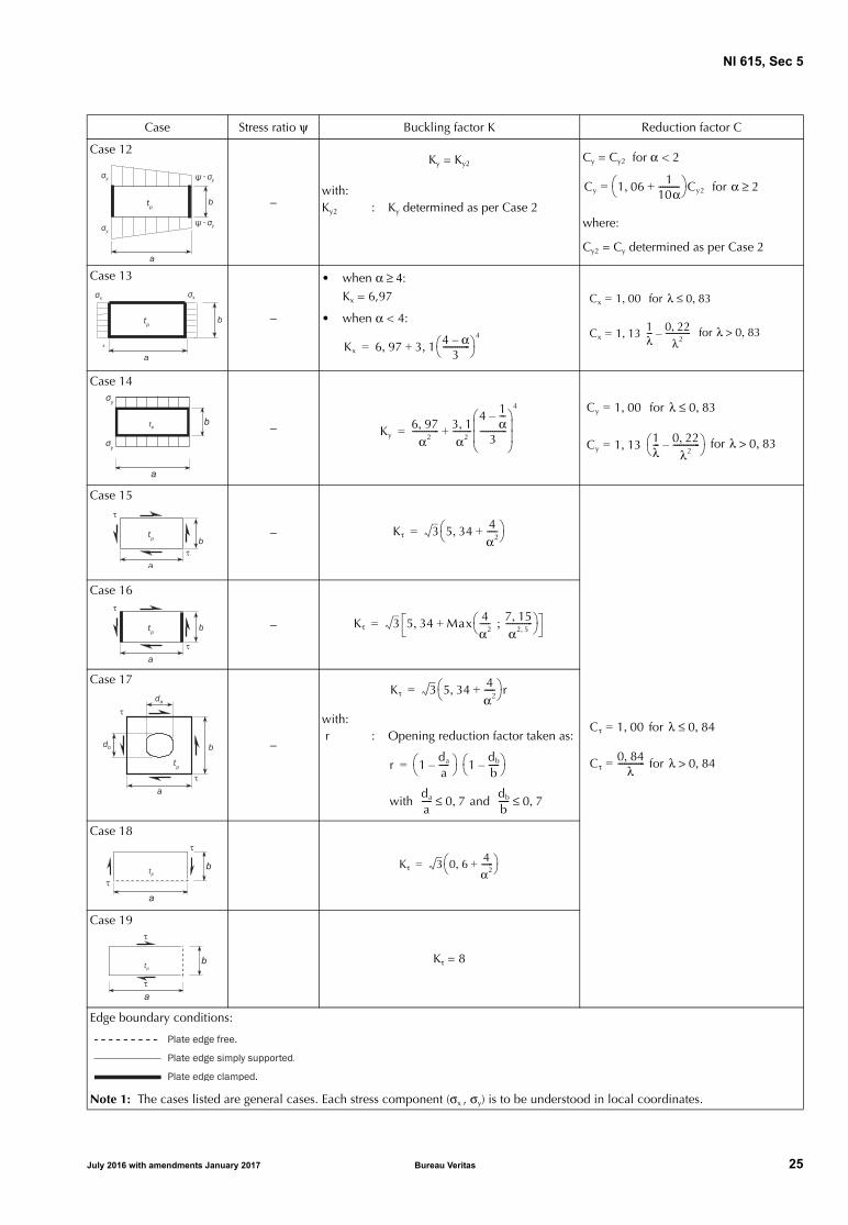
Case 12
−
Ky = Ky2Cy = Cy2 for α < 2
where:
Cy2 = Cy determined as per Case 2
with:Ky2 : Ky determined as per Case 2
Case 13
−
• when α ≥ 4:Kx = 6,97
• when α < 4:
Case 14
−
Case 15
−
Case 16
−
Case 17
−
with: r : Opening reduction factor taken as:
Case 18
Case 19
Kτ = 8
Edge boundary conditions:
Note 1: The cases listed are general cases. Each stress component (σx , σy) is to be understood in local coordinates.
Case Stress ratio ψ Buckling factor K Reduction factor C
Cy 1 06, 110α----------+
Cy2= for α 2≥
Kx 6 97, 3 1 4 α–3
------------- ,
4
+=
Cx 1 00,= for λ 0 83,≤
Cx 1 13 1λ--- 0 22,
λ2-------------–,= for λ 0 83,>
Ky6 97,
α2------------- 3 1,
α2---------
4 1α---–
3-------------
4
+=
Cy 1 00,= for λ 0 83,≤
Cy 1 13 1λ--- 0 22,
λ2-------------–
,= for λ 0 83,>
Kτ 3 5 34, 4α2-----+
=
Cτ 1 00,= for λ 0 84,≤
Cτ0 84,
λ-------------= for λ 0 84,>
Kτ 3 5 34, Max 4α2----- 7 15,
α2 5,-------------;
+=
Kτ 3 5 34, 4α2-----+
r=
r 1da
a-----–
1db
b-----–
=
with da
a----- 0 7,≤ and
db
b----- 0 7,≤
Kτ 3 0 6, 4α2------+
=
July 2016 with amendments January 2017 Bureau Veritas 25

NI 615, Sec 5
Table 5 : Buckling factor K and reduction factor C for curved plate panel with R/tp ≤ 2500
Case Aspect ratio Buckling factor K Reduction factor C
Case 1 • for general application:
Cax = 1,00 for λ ≤ 0,25
Cax = 1,233 − 0,933 λ for 0,25 < λ ≤ 1,0
• for curved single fields, e.g. bilge strakes, which are bounded by plane panels:
Case 2a
• for general application:
Ctg = 1,00 for λ ≤ 0,4
Ctg = 1,274 − 0,686 λ for 0,4 < λ ≤ 1,2
• for curved single fields, e.g. bilge strakes, which are bounded by plane panels:
Case 2b
Case 3
as in Case 2a
Case 4
Cτ = 1,00 for λ ≤ 0,4
Cτ = 1,274 − 0,686 λ for 0,4 < λ ≤ 1,2
Edge boundary conditions:
dR--- 0 5 R
tp
---,≤ K 1 23--- d2
Rtp
-------+=
Cax0 30,
λ3-------------= for 1 0, λ 1 5,≤<
Cax0 20,
λ2-------------= for λ 1 5,>
Cax0 65,
λ2------------- 1 0,≤=
dR--- 0 5 R
tp
---,> K 0 267 d2
Rtp
------- 3 dR--- tp
R---– 0 4 d2
Rtp
-------,≥,=
dR--- 1 63 R
tp
---,≤ K dRtp
------------ 3 Rtp( )0 175,
d0 35,----------------------+=
Ctg0 65,
λ2-------------= for λ 1 2,>
Ctg0 8,λ2--------- 1 0,≤=d
R--- 1 63 R
tp
---,> K 0 3 d2
R2-----, 2 25 R2
d tp
---------
2
,+=
dR--- R
tp
---≤ K 0 6d,Rtp
-------------= Rtp
d------------ 0 3
Rtp
d2-------,–+
dR--- R
tp
---> K 0 3 d2
R2-----, 0 291 R2
d tp
---------
2
,+=
dR--- 8 7 R
tp
---,≤ K 3 28 3, 0 67 d3,R1 5, tp
1 5,---------------------+=
Cτ0 65,
λ2-------------= for λ 1 2,>d
R--- 8 7 R
tp
---,> K 3 0 28d, 2
R Rtp
-------------------=
26 Bureau Veritas July 2016 with amendments January 2017
NI 615, Sec 5
The shear stress τ, in N/mm2, to be applied for the platepanel capacity calculation as given in [2.2.1], is to be takenas follows:
• for FE analysis, the reference shear stresses as defined inSec 4, [2.4]
• for prescriptive assessment, the shear stresses at loadcalculation points of the considered elementary platepanel, as defined in the applicable Rules
• for grillage beam analysis, τ = 0 in the attached bucklingpanel.
2.3 Stiffeners
2.3.1 Buckling modes
The following buckling modes are to be checked:
• stiffener induced failure (SI)
• associated plate induced failure (PI).
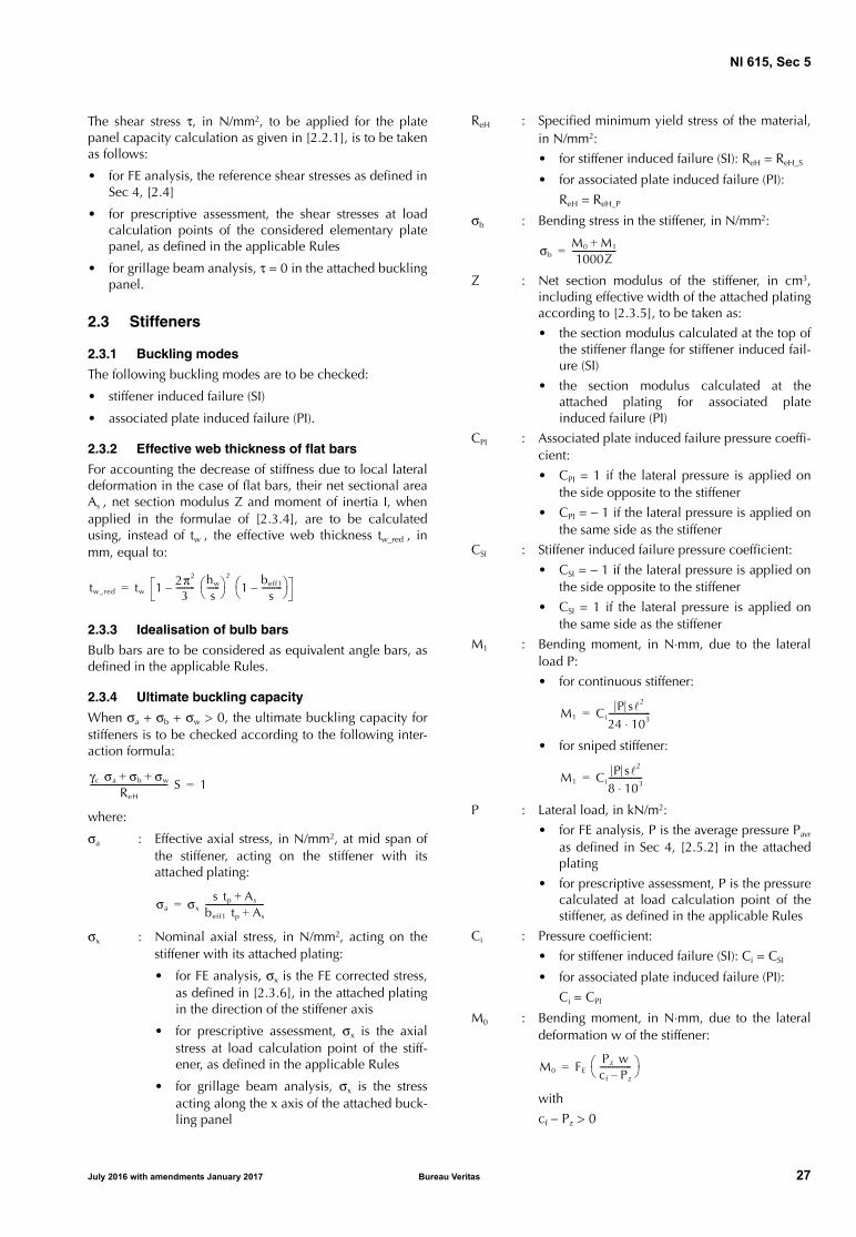
2.3.2 Effective web thickness of flat bars
For accounting the decrease of stiffness due to local lateraldeformation in the case of flat bars, their net sectional areaAs , net section modulus Z and moment of inertia I, whenapplied in the formulae of [2.3.4], are to be calculatedusing, instead of tw , the effective web thickness tw_red , inmm, equal to:
2.3.3 Idealisation of bulb bars
Bulb bars are to be considered as equivalent angle bars, asdefined in the applicable Rules.
2.3.4 Ultimate buckling capacity
When σa + σb + σw > 0, the ultimate buckling capacity forstiffeners is to be checked according to the following inter-action formula:
where:
σa : Effective axial stress, in N/mm2, at mid span ofthe stiffener, acting on the stiffener with itsattached plating:
σx : Nominal axial stress, in N/mm2, acting on thestiffener with its attached plating:
• for FE analysis, σx is the FE corrected stress,as defined in [2.3.6], in the attached platingin the direction of the stiffener axis
• for prescriptive assessment, σx is the axialstress at load calculation point of the stiff-ener, as defined in the applicable Rules
• for grillage beam analysis, σx is the stressacting along the x axis of the attached buck-ling panel
ReH : Specified minimum yield stress of the material,in N/mm2:
• for stiffener induced failure (SI): ReH = ReH_S
• for associated plate induced failure (PI):
ReH = ReH_P
σb : Bending stress in the stiffener, in N/mm2:
Z : Net section modulus of the stiffener, in cm3,including effective width of the attached platingaccording to [2.3.5], to be taken as:
• the section modulus calculated at the top ofthe stiffener flange for stiffener induced fail-ure (SI)
• the section modulus calculated at theattached plating for associated plateinduced failure (PI)
CPI : Associated plate induced failure pressure coeffi-cient:
• CPI = 1 if the lateral pressure is applied onthe side opposite to the stiffener
• CPI = − 1 if the lateral pressure is applied onthe same side as the stiffener
CSI : Stiffener induced failure pressure coefficient:
• CSI = − 1 if the lateral pressure is applied onthe side opposite to the stiffener
• CSI = 1 if the lateral pressure is applied onthe same side as the stiffener
M1 : Bending moment, in N⋅mm, due to the lateralload P:
• for continuous stiffener:
• for sniped stiffener:
P : Lateral load, in kN/m2:
• for FE analysis, P is the average pressure Pavr
as defined in Sec 4, [2.5.2] in the attachedplating
• for prescriptive assessment, P is the pressurecalculated at load calculation point of thestiffener, as defined in the applicable Rules
Ci : Pressure coefficient:
• for stiffener induced failure (SI): Ci = CSI
• for associated plate induced failure (PI):
Ci = CPI
M0 : Bending moment, in N⋅mm, due to the lateraldeformation w of the stiffener:
with
cf − Pz > 0
tw_red tw 1 2π2
3--------- hw
s------
2
1beff1
s----------–
–=
γc σa σb σw+ +ReH
------------------------------------- S 1=
σa σx s tp As+
beff1 tp As+----------------------------=
σbM0 M1+1000Z---------------------=
M1 CiP s2
24 103⋅--------------------=
M1 CiP s2
8 103⋅----------------=
M0 FE Pz wcf Pz–---------------
=
July 2016 with amendments January 2017 Bureau Veritas 27

NI 615, Sec 5
FE : Ideal elastic buckling force of the stiffener, in N:
I : Moment of inertia of the stiffener, in cm4,including effective width of the attached platingaccording to [2.3.5].
I is to satisfy the following criterion:
tp : Net thickness of the attached plating, in mm, tobe taken as:
• for prescriptive requirements: the meanthickness of the two attached plating panels
• for FE analysis: the thickness of the consid-ered EPP on one side of the stiffener
Pz : Nominal lateral load, in N/mm2, acting on thestiffener due to stresses, σx , σy and τ, in theattached plating in way of the stiffener mid-span:
σy : Stress applied on the edge along the y axis ofthe buckling panel, in N/mm2, without beingtaken less than 0:
• for FE analysis, σy is the FE corrected stress,as defined in [2.3.6], in the attached platingin the direction perpendicular to the stiff-ener axis
• for prescriptive assessment, σy is the maxi-mum compressive stress at load calculationpoints of the stiffener attached plating, asdefined in the applicable Rules
• for grillage beam analysis, σy is the stressacting along the y axis of the attached buck-ling panel
τ : Applied shear stress, in N/mm2:
• for FE analysis, τ is the reference shearstress, as defined in Sec 4, [2.4.2], in theattached plating
• for prescriptive assessment, τ is the shearstress at load calculation point of the stiff-ener attached plating, as defined in theapplicable Rules
• for grillage beam analysis, τ = 0 in theattached buckling panel
m1 , m2 : Coefficients taken equal to:
• when α ≥ 2: m1 = 1,47 and m2 = 0,49
• when α < 2: m1 = 1,96 and m2 = 0,37
c : Factor taking into account the stresses in theattached plating acting perpendicular to thestiffener axis:
• for 0 ≤ ψ ≤ 1: c = 0,5 (1 + ψ)
•
ψ : Edge stress ratio for case 2 according to Tab 4
w : Deformation of stiffener, in mm:
w = w0 + w1
w0 : Assumed imperfection, in mm, to be taken as:
• in general:
w0 = / 1000
• for stiffeners sniped at both ends, consider-ing stiffener induced failure (SI):
w0 = − wna
• for stiffeners sniped at both ends, consider-ing associated plate induced failure (PI):
w0 = wna
wna: : Distance from the mid-point of attached platingto the neutral axis of the stiffener calculatedwith the effective width of the attached platingaccording to [2.3.5]
w1 : Deformation of the stiffener, in mm, at mid-point of the stiffener span, due to lateral load P.
In case of uniformly distributed load, w1 is to betaken as:
• in general:
• for stiffeners sniped at both ends:
cf : Elastic support provided by the stiffener, inN/mm2:
with:
cxa : Coefficient to be taken as:
•
•
FEπ---
2
E I 104=
Is tp
3
12 104⋅--------------------≥
Pztp
s--- σxl
π s--------
2
2c γ σy 2τ1+ +=
σxl γ σx 1As
stp
------+ = 0≥
τ1 γ τ tp ReH_p E m1
a2------- m2
b2-------+
–= 0≥
for ψ 0< : c 12 1 ψ–( )----------------------=
w1 Ci P s4
384 107⋅ EI-------------------------------=
w1 Ci 5 P s4
384 107⋅ EI-------------------------------=
cf FE π---
2
1 cp+( )=
cp1
1 0 91,cxa
------------- 12Istp
3--------104 1– +
----------------------------------------------------------=
for 2s≥ : cxa
2s------ 2s
------+
2
=
for 2s< : cxa 1 2s------
2
+2
=
28 Bureau Veritas July 2016 with amendments January 2017

NI 615, Sec 5
Table 6 : Moments of inertia IP , IT and Iω
σw : Stress due to torsional deformation, in N/mm2,to be taken as:
• for stiffener induced failure (SI):
• for associated plate induced failure (PI):
σw = 0
yw : Distance, in mm, from the centroid of the stiff-ener cross-section to the free edge of the stiff-ener flange, to be taken as:
• for flat bars:
• for angle and bulb bars:
• for T-bars:
Φ0 : Coefficient taken as:
σET : Reference stress for torsional buckling, inN/mm2:
IP : Net polar moment of inertia of the stiffener, incm4, about point C (see Fig 1), as defined in Tab 6
IT : Net Saint Venant’s moment of inertia of the stiff-ener, in cm4, as defined in Tab 6
Iω : Net sectional moment of inertia of the stiffener,in cm6, about point C (see Fig 1), as defined inTab 6
ε : Degree of fixation:
Aw : Net area of the stiffener web, in mm2
Af : Net area of the stiffener flange, in mm2.
2.3.5 Effective width of attached plating
The effective width beff , in mm, of the stiffener attachedplating is to be taken as:
• when σx > 0:
- for FE analysis:
beff = Min (Cx b ; χs s)
- for prescriptive assessment:
• when σx ≤ 0:
beff = χs s
where:
χs : Effective width coefficient to be taken as:
• for eff /s ≥ 1:
• for eff /s < 1:
Flat bars (1) Bulb bars, angle bars and T-bars
• for bulb and angle bars:
• for T-bars:
(1) tw is the net web thickness, in mm (see Fig 1). tw_red as defined in [2.3.2] is not to be used in this Table.
IPhw
3 tw
3 104⋅----------------= IP
Aw ef 0 5tf,–( )2
3--------------------------------------- Af ef
2+ 10 4–=
IThw tw
3
3 104⋅---------------- 1 0 63
tw
hw
------,– = IT
ef 0 5tf,–( ) tw3
3 104⋅----------------------------------- 1 0 63
tw
ef 0 5tf,–-----------------------,–
bf tf3
3 104⋅---------------- 1 0 63
tf
bf
----,– +=
Iωhw
3 tw3
36 106⋅--------------------=
IωAf ef
2 bf2
12 106⋅--------------------- Af 2 6Aw,+
Af Aw+---------------------------- =
Iωbf
3 tf ef2
12 106⋅--------------------=
σw E yw tf
2--- hw+ Φ0
π---
2
1
10 4ReH_S,
σET
----------------------–-------------------------------- 1–
=
ywtw
2----=
yw bfhw tw
2 tf bf2+
2As
------------------------------ –=
ywbf
2----=
Φ0
hw
------ 10 3–=
σETEIP
--- επ2 Iω 102
2
-------------------------- 0 385IT,+ =
ε 1
π---
2
10 3–
Iω 0 75s,tp3
--------------- ef 0 5tf,–tw3
-----------------------+
--------------------------------------------------------------+=
beff Min Cx1 b1 Cx2 b2+
2--------------------------------------- χss; =
χs Min 1 12,
1 1 75,eff
s-------
1 6,------------------+
---------------------------- 1 0,;=
χs 0 407eff
s-------,=
July 2016 with amendments January 2017 Bureau Veritas 29

NI 615, Sec 5
eff : Effective length of the stiffener, in mm, taken as:
• for a stiffener fixed at both ends:
• for a stiffener simply supported at one endand fixed at the other:
eff = 0,75
• for a stiffener simply supported at both ends:
eff =
2.3.6 FE corrected stresses for stiffener capacity
When the reference stresses σx and σy obtained by FE analy-sis according to Sec 4, [2.4] are both compressive, they areto be corrected according to the following formulae:
• if σx < ν σy:
σxcor = 0
σycor = σy
• if σy < ν σx:
σxcor = σx
σycor = 0
• in the other cases:
σxcor = σx − ν σy
σycor = σy − ν σx
2.4 Primary supporting members
2.4.1 Web plate in way of openings
The web plate of primary supporting members with open-ings is to be assessed for buckling based on the combinedaxial compressive and shear stresses.
The web plate adjacent to the opening on both sides is to beconsidered as individual unstiffened plate panels as shownin Tab 7.
The interaction formulae of [2.2.1] are to be used with:
• σx = σav
• σy = 0
• τ = τav
where:
σav : Weighted average compressive stress, in N/mm2,in the area of web plate being considered, i.e.P1, P2 or P3 as shown in Tab 7
τav : Weighted average shear stress, in N/mm2:
• for opening modelled in primary supportingmembers:
τav is the weighted average shear stress in thearea of web plate being considered, i.e. P1,P2 or P3 as shown in Tab 7
• for opening not modelled in primary sup-porting members:
τav is the weighted average shear stress givenin Tab 7.
2.4.2 Reduction factors of web plate in way of openings
The reduction factors, Cx or Cy in combination with Cτ , ofthe plate panel(s) of the web adjacent to the opening is tobe taken as shown in Tab 7.
2.4.3 The equivalent plate panel of web plate of primarysupporting members crossed by perpendicular stiffeners isto be idealised as shown in Fig 2.
Figure 2 : Web plate idealisation
The correction of panel breadth is also applicable for other slot configurations, provided the web or the collar plate is attached to at least oneside of the passing stiffener.
eff
3-------=
0,5hstf
30 Bureau Veritas July 2016 with amendments January 2017

NI 615, Sec 5
Table 7 : Reduction factors Cx , Cy and Cτ
Configuration Cx and Cy
Cτ
Opening modelled in PSM
Opening not modelled in PSM
(a) Without edge reinforcements:Separate reductionfactors are to beapplied to areas P1and P2 using case 3or case 6 in Tab 4,with edge stress ratioψ = 1,0
Separate reductionfactors are to beapplied to areas P1and P2 using case 18or case 19 in Tab 4
• when case 17 of Tab 4 isapplicable:A common reductionfactor is to be applied toareas P1 and P2 usingcase 17 in Tab 4 with:τav = τav(web)
• when case 17 of Tab 4 is not applicable:Separate reduction fac-tors are to be applied to areas P1 and P2 using case 18 or case 19 in Tab 4 with:
(b) With edge reinforcements:Separate reductionfactors are to beapplied to areas P1and P2 using, in Tab4 Cx for case 1 or Cy
for case 2, with edgestress ratio ψ = 1,0
Separate reductionfactors are to beapplied to areas P1and P2 using case 15in Tab 4
Separate reduction factorsare to be applied to areas P1and P2 using case 15 in Tab4, with:
(c) Example of hole in web:Panels P1 and P2 are to be evaluated in accordancewith configuration (a)Panel P3 is to be evaluated in accordance with con-figuration (b)
Note 1:h : Height, in m, of the web of the primary supporting member in way of the openingh0 : Height, in m, of the opening measured in the depth of the webτav(web) : Weighted average shear stress, in N/mm2 over the web height h of the primary supporting member.
Note 2: Web panels to be considered for buckling in way of openings are shown shaded and numbered P1, P2, etc.
τavτav (web) h⋅
h h0–-----------------------------=
τavτav (web) h⋅
h h0–-----------------------------=
July 2016 with amendments January 2017 Bureau Veritas 31
NI 615, Sec 5
3 Buckling capacity of the other structures
3.1 Struts, pillars and cross ties
3.1.1 Buckling utilisation factor
The buckling utilisation factor η, for axially compressedstruts, pillars and cross ties, is to be taken as:
where:
σav : Average axial compressive stress in the member,in N/mm2
σcr : Minimum critical buckling stress, in N/mm2,taken as:
• for σE ≤ 0,5 ReH_S:
σcr = σE
• for σE > 0,5 ReH_S:
σE : Minimum elastic compressive buckling stress,in N/mm2, according to [3.1.2] to [3.1.4]
ReH_S : Specified minimum yield stress of the consid-ered member, in N/mm2. For built-up members,the lowest specified minimum yield stress is tobe used.
3.1.2 Elastic column buckling stress
The elastic compressive column buckling stress σEC , inN/mm2, of members subject to axial compression is to betaken as:
where:
A : Net cross-sectional area of the member, in cm2
I : Net moment of inertia about the weakest axis ofthe cross-section, in cm4
pill : Length of the member, in m:
• for pillars and struts:
pill is the unsupported length of the member
• for cross ties:
- in centre tanks: pill is the distancebetween the flanges of longitudinal stiff-eners on the starboard and port longitu-dinal bulkheads to which the cross tie’shorizontal stringer is attached
- in wing tanks: pill is the distancebetween the flanges of longitudinal stiff-eners on the longitudinal bulkhead towhich the cross tie’s horizontal stringeris attached, and the inner hull plating.
fend : End constraint factor, taken as:
• for pillars and struts:
- fend = 1,0 where both ends are simplysupported
- fend = 2,0 where one end is simply sup-ported and the other end is fixed
- fend = 4,0 where both ends are fixed
• for cross ties:
fend = 2,0
A pillar end may be considered fixed when brackets of ade-quate size are fitted. Such brackets are to be supported bystructural members with bending stiffness greater than thepillar.
3.1.3 Elastic torsional buckling stress
The elastic torsional buckling stress σET , in N/mm2, withrespect to axial compression of members is to be taken as:
where:
Isv : Net Saint Venant’s moment of inertia, in cm4
(see Tab 8 for examples of cross-sections)
Ipol : Net polar moment of inertia about the shear
centre of cross-section, in cm4, taken as:
Ipol = Iy + Iz + A (y02 + z0
2)
cwarp : Warping constant, in cm6 (see Tab 8 for exam-ples of cross-sections)
pill : Length of the member, in m, as defined in[3.1.2]
Iy : Net moment of inertia about the y axis, in cm4
Iz : Net moment of inertia about the z axis, in cm4
A : Net cross-sectional area of the member, in cm2
y0 : Transverse position of shear centre relative tothe cross-sectional centroid, in cm (see Tab 8 forexamples of cross-sections)
z0 : Vertical position of shear centre relative to thecross-sectional centroid, in cm (see Tab 8 forexamples of cross-sections).
η σav
σcr
-------=
σcr 1ReH_S
4σE
------------– ReH_S=
σEC π2 Efend IA pill
2--------------- 10 4–=
σETGIsv
Ipol
---------- π2 fend Ecwarp
Ipol pill2
--------------------------------- 10 4–+=
32 Bureau Veritas July 2016 with amendments January 2017
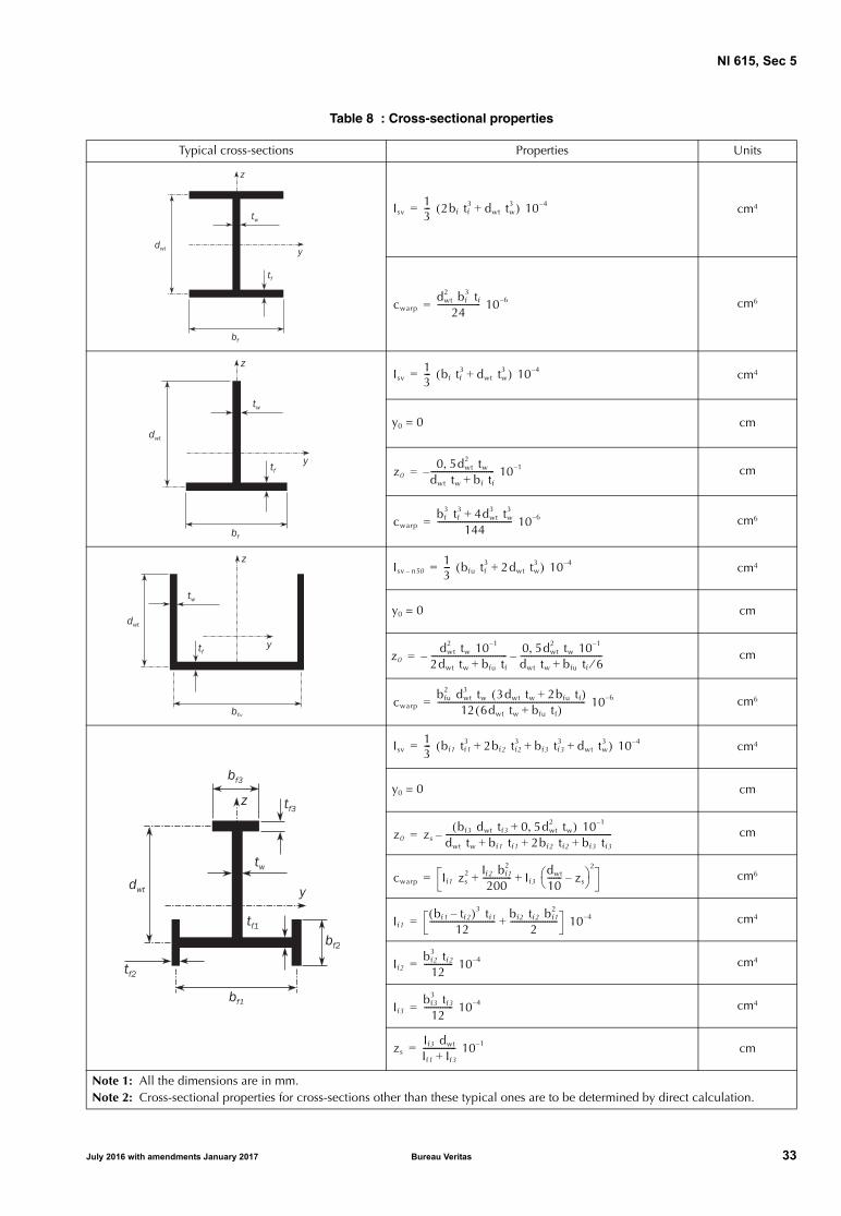
NI 615, Sec 5
Table 8 : Cross-sectional properties
Typical cross-sections Properties Units
cm4
cm6
cm4
y0 = 0 cm
cm
cm6
cm4
y0 = 0 cm
cm
cm6
cm4
y0 = 0 cm
cm
cm6
cm4
cm4
cm4
cm
Note 1: All the dimensions are in mm.Note 2: Cross-sectional properties for cross-sections other than these typical ones are to be determined by direct calculation.
Isv13--- 2bf tf
3 dwt tw3+( ) 10 4–=
cwarpdwt
2 bf3 tf
24--------------------- 10 6–=
Isv13--- bf tf
3 dwt tw3+( ) 10 4–=
z00 5dwt
2 tw,dwt tw bf tf+------------------------------- 10 1––=
cwarpbf
3 tf3 4dwt
3 tw3+
144------------------------------------ 10 6–=
Isv n50–13--- bfu tf
3 2dwt tw3+( ) 10 4–=
z0dwt
2 tw 10 1–
2dwt tw bfu tf+-------------------------------------– 0 5dwt
2 tw 10 1–,dwt tw bfu tf 6⁄+----------------------------------------–=
cwarpbfu
2 dwt3 tw 3dwt tw 2bfu tf+( )12 6dwt tw bfu tf+( )
------------------------------------------------------------------------ 10 6–=
Isv13--- bf1 tf1
3 2bf2 tf23 bf3 tf3
3 dwt tw3+ + +( ) 10 4–=
z0 zsbf3 dwt tf3 0 5dwt
2 tw,+( ) 10 1–
dwt tw bf1 tf1 2bf2 tf2 bf3 tf3+ + +---------------------------------------------------------------------------------–=
cwarp If1 zs2 If2 bf1
2
200-------------- If3
dwt
10------- zs–
2
+ +=
If1bf1 tf2–( )3 tf1
12-------------------------------- bf2 tf2 bf1
2
2-----------------------+ 10 4–=
If2bf2
3 tf2
12-------------- 10 4–=
If3bf3
3 tf3
12-------------- 10 4–=
zsIf3 dwt
If1 If3+---------------- 10 1–=
July 2016 with amendments January 2017 Bureau Veritas 33

NI 615, Sec 5
3.1.4 Elastic torsional/column buckling stress
For the cross-sections where the centroid and the shear cen-tre do not coincide, the interaction between the torsionaland column buckling modes is to be examined.
The elastic torsional/column buckling stress σETF , in N/mm2,with respect to axial compression is to be taken as:
where:
σEC : Elastic compressive column buckling stress, asdefined in [3.1.2]
σET : Elastic torsional buckling stress, as defined in[3.1.3]
ζ : Coefficient taken as:
y0 , z0 , Ipol : As defined in [3.1.3]A : Net cross-sectional area of the member, in cm2.
3.2 Corrugated bulkheads
3.2.1 The buckling utilisation factor of flange and web ofcorrugations of corrugated bulkheads is based on the com-bination of in-plane stresses and shear stress.The interaction formulae of [2.2.1] are to be used consider-ing the following coefficients:• α = 2• ψx = ψy = 1
σETF1
2ζ------ σEC σET+( ) σEC σET+( )2 4ζ σEC σET––[ ]=
ζ 1y0
2 z+ 02( ) A
Ipol
----------------------------–=
34 Bureau Veritas July 2016 with amendments January 2017

NI 615, App 1
APPENDIX 1 STRESS BASED REFERENCE STRESSES
Symbols
a : Length, in mm, of the longer side of the platepanel as defined in Sec 5
b : Length, in mm, of the shorter side of the platepanel as defined in Sec 5
Αi : Area, in mm2, of the i-th plate element of thebuckling panel
n : Number of plate elements in the buckling panel
σxi : Actual stress, in N/mm2, at the centroid of the i-th plate element in x direction, applied alongthe shorter edge of the buckling panel
σyi : Actual stress, in N/mm2, at the centroid of the i-th plate element in y direction, applied alongthe longer edge of the buckling panel
ψ : Edge stress ratio as defined in Sec 5
τi : Αctual membrane shear stress, in N/mm2, at thecentroid of the i-th plate element of the buck-ling panel.
1 Stress based method
1.1 Introduction
1.1.1 This Appendix provides a method to determine stressdistribution along the edges of the considered bucklingpanel by 2nd order polynomial curve, by linear distributionusing the least square method and by weighted averageapproach. This method is called Stress based method.
The reference stress is the stress components at centre of theplate element transferred into the local system of the con-sidered buckling panel.
1.1.2 Definition
A regular panel is a plate panel of rectangular shape. Anirregular panel is a plate panel which is not regular, asdetailed in Sec 4, [2.3.1].
1.2 Stress application
1.2.1 Regular panel
The reference stresses are to be taken as defined in [2.1] fora regular panel when the following conditions are satisfied:
• at least one plate element centre is located in each thirdpart of the long edge a of a regular panel, and
• this element centre is located at a distance in the panellocal x direction not less than a/4 to at least one of theelement centres in the adjacent third part of the panel.
Otherwise, the reference stresses are to be taken as definedin [2.2] for an irregular panel.
1.2.2 Irregular panel and curved panel
The reference stresses of an irregular panel or a curvedpanel are to be taken as defined in [2.2].
2 Reference stresses
2.1 Regular panel
2.1.1 Longitudinal stress
The longitudinal stress σx applied on the shorter edge of thebuckling panel is to be calculated as follows:
• for plate buckling assessment, the distribution of σx(x) isassumed as 2nd order polynomial curve:
σx(x) = C x2 + D x + E
The best fitting curve σx(x) is to be obtained by minimis-ing the square error Π, considering the area of each ele-ment as a weighting factor:
The unknown coefficients C, D and E must yield zerofirst partial derivatives ∂Π with respect to C, D and Erespectively:
The unknown coefficients C, D and E are obtained bysolving the three above equations.
Π Ai σxi Cxi2 Dxi E+ +( )–[ ]2
i 1=
n
=
C∂∂Π 2 Aixi
2 σxi Cxi2 Dxi E+ +( )–[ ]
i 1=
n
0= =
D∂∂Π 2 Aixi σxi Cxi
2 Dxi E+ +( )–[ ]i 1=
n
0= =
E∂∂Π 2 Ai σxi Cxi
2 Dxi E+ +( )–[ ]i 1=
n
0= =
July 2016 with amendments January 2017 Bureau Veritas 35
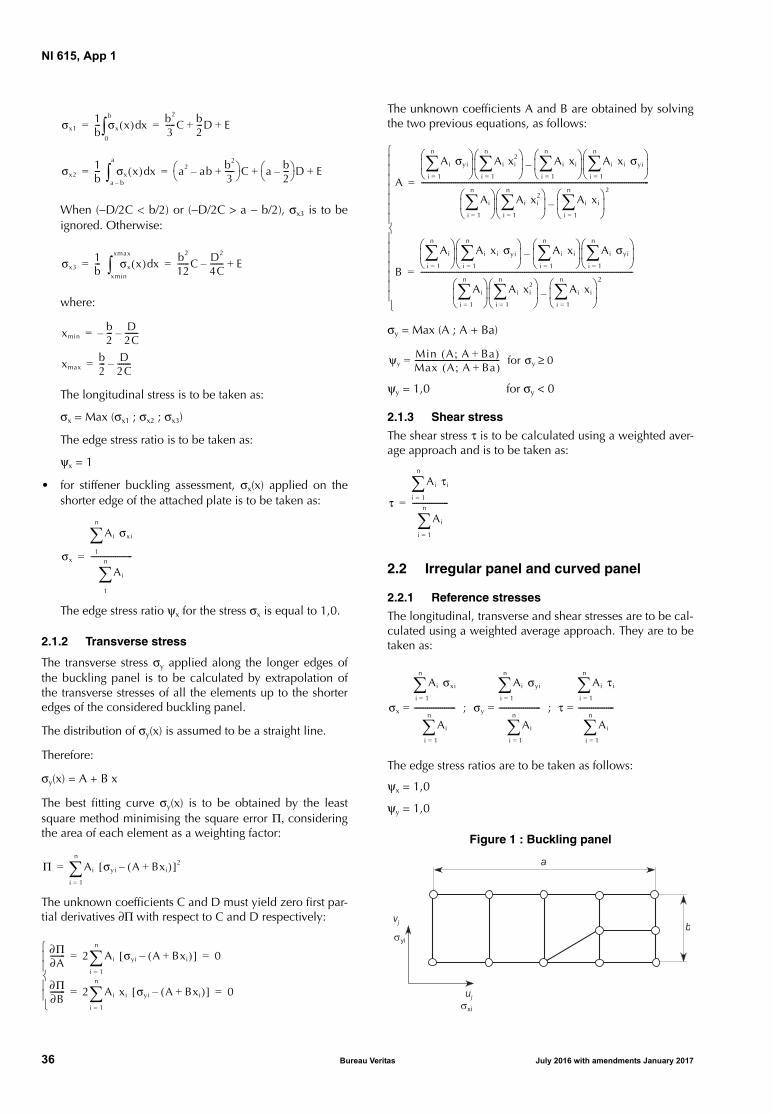
NI 615, App 1
When (−D/2C < b/2) or (−D/2C > a − b/2), σx3 is to beignored. Otherwise:
where:
The longitudinal stress is to be taken as:
σx = Max (σx1 ; σx2 ; σx3)
The edge stress ratio is to be taken as:
ψx = 1
• for stiffener buckling assessment, σx(x) applied on theshorter edge of the attached plate is to be taken as:
The edge stress ratio ψx for the stress σx is equal to 1,0.
2.1.2 Transverse stress
The transverse stress σy applied along the longer edges ofthe buckling panel is to be calculated by extrapolation ofthe transverse stresses of all the elements up to the shorteredges of the considered buckling panel.
The distribution of σy(x) is assumed to be a straight line.
Therefore:
σy(x) = A + B x
The best fitting curve σy(x) is to be obtained by the leastsquare method minimising the square error Π, consideringthe area of each element as a weighting factor:
The unknown coefficients C and D must yield zero first par-tial derivatives ∂Π with respect to C and D respectively:
The unknown coefficients A and B are obtained by solvingthe two previous equations, as follows:
σy = Max (A ; A + Ba)
ψy = 1,0 for σy < 0
2.1.3 Shear stress
The shear stress τ is to be calculated using a weighted aver-age approach and is to be taken as:
2.2 Irregular panel and curved panel
2.2.1 Reference stresses
The longitudinal, transverse and shear stresses are to be cal-culated using a weighted average approach. They are to betaken as:
The edge stress ratios are to be taken as follows:
ψx = 1,0
ψy = 1,0
Figure 1 : Buckling panel
σx11b--- σx x( ) xd
0
b
b2
3-----C b
2---D E+ += =
σx21b--- σx x( ) xd
a b–
a
a2 ab– b2
3-----+
C a b2---–
D E+ += =
σx31b--- σx x( ) xd
xmin
xmax
b2
12------C D2
4C-------– E+= =
xminb2---– D
2C-------–=
xmaxb2--- D
2C-------–=
σx
Ai σxi
1
n
Ai
1
n
----------------------=
Π Ai σyi A Bxi+( )–[ ]2
i 1=
n
=
∂Π∂A-------- 2 Ai σyi A Bxi+( )–[ ]
i 1=
n
0= =
∂Π∂B-------- 2 Ai xi σyi A Bxi+( )–[ ]
i 1=
n
0= =
A
Ai σyi
i 1=
n
Ai xi
2
i 1=
n
Ai xi
i 1=
n
Ai xi σyi
i 1=
n
–
Ai
i 1=
n
Ai xi
2
i 1=
n
Ai xi
i 1=
n
2
–
-------------------------------------------------------------------------------------------------------------------------=
B
Ai
i 1=
n
Ai xi σyi
i 1=
n
Ai xi
i 1=
n
Ai σyi
i 1=
n
–
Ai
i 1=
n
Ai xi
2
i 1=
n
Ai xi
i 1=
n
2
–
-----------------------------------------------------------------------------------------------------------------=
ψyMin A A Ba+;( )Max A A Ba+;( )---------------------------------------------= for σy 0≥
τ
Ai τi
i 1=
n
Ai
i 1=
n
-------------------=
σx
Ai σxi
i 1=
n
Ai
i 1=
n
----------------------= ; σy
Ai σyi
i 1=
n
Ai
i 1=
n
----------------------= ; τ
Ai τi
i 1=
n
Ai
i 1=
n
-------------------=
yi
xi
36 Bureau Veritas July 2016 with amendments January 2017

NI 615, App 2
APPENDIX 2 METHOD SELECTION FOR DIRECT STRENGTH ANALYSIS OF PANELS
1 Stiffened and unstiffened panels
1.1 General
1.1.1 This Appendix provides guidance for the selection ofthe modelling method of plate panels, when assessed forbuckling through direct strength analysis according to Sec 4
1.1.2 The plate panels of hull structure are to be modelled asstiffened or unstiffened panels. Method A or Method B asdefined in Sec 1, [2] is to be used according to Fig 1to Fig 11.
Table 1 : Structural members
Structural elementsAssessment
methodNormal panel definition
Longitudinal structure (see Fig 1, Fig 2 and Fig 7)
Longitudinally stiffened panelsShell envelopeDeckInner hullHopper tank sidesLongitudinal bulkheads
SP-A length: between web frames width: between primary supporting members
Double bottom longitudinal girders in line with longitudinal bulkheads or connected to hopper tank sides
SP-A length: between web frameswidth: full web depth
Web of double bottom longitudinal girders not in line with lon-gitudinal bulkheads or not connected to hopper tank sides
SP-B length: between web frameswidth: full web depth
Web of horizontal girders in double side spaces connected to hopper tank sides
SP-A length: between web frameswidth: full web depth
Web of horizontal girders in double side spaces not connected to hopper tank sides
SP-B length: between web frameswidth: full web depth
Web of single skin longitudinal girders or stringers UP-B plate between local stiffeners/face plate/PSM
Transverse structure (see Fig 3 Fig 4, Fig 5, Fig 8 and Fig 11)
Web of transverse deck frames, including brackets UP-B plate between local stiffeners/face plate/PSM
Vertical web in double side spaces SP-B length: full web depth width: between primary supporting members
Irregularly stiffened panels, e.g. web panels in way of hopper tanks and bilges
UP-B plate between local stiffeners/face plate/PSM
Double bottom floors SP-B length: full web depth width: between primary supporting members
Vertical web frames, including brackets UP-B plate between vertical web stiffeners/face plate/PSM
Cross tie web plates UP-B plate between vertical web stiffeners/face plate/PSM
Transverse watertight bulkheads (see Fig 6, Fig 9 and Fig 10)
Regularly stiffened bulkhead panels including the secondary buckling stiffeners perpendicular to the regular stiffeners (such as carlings)
SP-A length: between primary supporting memberswidth: between primary supporting members
Irregularly stiffened bulkhead panels, e.g. web panels in way of hopper tanks and bilges
UP-B plate between local stiffeners/face plate
Web plate of bulkhead stringers, including brackets UP-B plate between web stiffeners/face plate
Transverse corrugated bulkheads and cross deck
Cross deck SP-A plate between local stiffeners/PSM
Note 1:SP, UP : Stiffened panel and Unstiffened panel, respectivelyA, B : Method A and Method B, respectivelyPSM : Primary supporting member.
July 2016 with amendments January 2017 Bureau Veritas 37
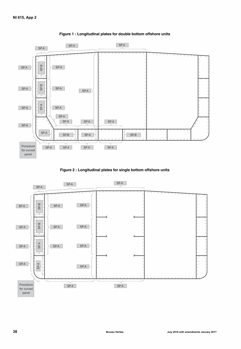
NI 615, App 2
Figure 1 : Longitudinal plates for double bottom offshore units
Figure 2 : Longitudinal plates for single bottom offshore units
38 Bureau Veritas July 2016 with amendments January 2017

NI 615, App 2
Figure 3 : Transverse web frames for double bottom offshore units
Figure 4 : Transverse web frames for single bottom offshore units
July 2016 with amendments January 2017 Bureau Veritas 39
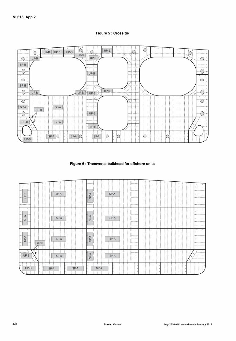
NI 615, App 2
Figure 5 : Cross tie
Figure 6 : Transverse bulkhead for offshore units
40 Bureau Veritas July 2016 with amendments January 2017

NI 615, App 2
Figure 7 : Longitudinal plates for container ships
Figure 8 : Transverse web frames for container ships
UP-B
SP-A
SP-A
SP-B
Procedurefor curved
panel
SP-A SP-A SP-A SP-A SP-A SP-A
SP-A SP-A SP-A SP-A SP-A SP-A
UP-B
UP-ASP-B
SP-B SP-B SP-B SP-B SP-B
SP-A
SP-A
UP-B
UP-B
SP-B SP-B SP-BSP-BSP-B SP-B
UP-B
SP-B
SP-B UP-B
Procedure for opening isto be applied for panelsfitted with openings
UP-B
UP-B
UP-B
July 2016 with amendments January 2017 Bureau Veritas 41
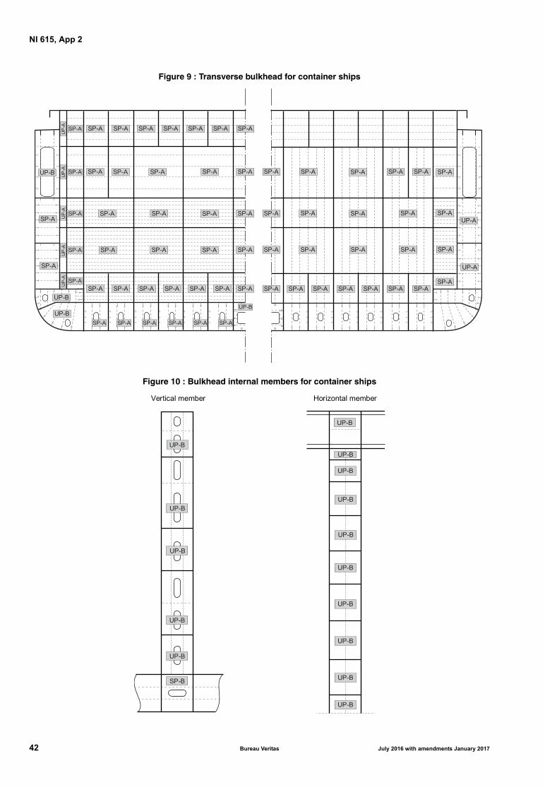
NI 615, App 2
Figure 9 : Transverse bulkhead for container ships
Figure 10 : Bulkhead internal members for container ships
UP-B
UP-B
SP-A SP-A SP-ASP-ASP-A SP-A
UP-B
SP-A SP-A SP-A SP-A SP-A SP-A
SP-A SP-A SP-A SP-A
SP-A SP-A SP-A SP-A
SP-A SP-A SP-A SP-A
SP-A SP-A SP-A SP-A SP-A SP-A SP-A
SP-A
SP-A
SP-A
SP-A
SP-A
SP-AUP-B
SP-A
SP-A
SP-A
UP
-AU
P-A
UP
-AU
P-A
UP
-A
UP-A
UP-A
SP-A
SP-A
SP-A
SP-A
SP-A
SP-A
SP-A
SP-A SP-A SP-A SP-A SP-A SP-A
SP-A SP-A
SP-A SP-A
SP-A SP-A SP-A SP-A
SP-A
SP-A
SP-A
UP-B
UP-B
UP-B
UP-B
UP-B
SP-B
Vertical member
UP-B
UP-B
UP-B
UP-B
UP-B
UP-B
UP-B
UP-B
UP-B
Horizontal member
UP-B
42 Bureau Veritas July 2016 with amendments January 2017
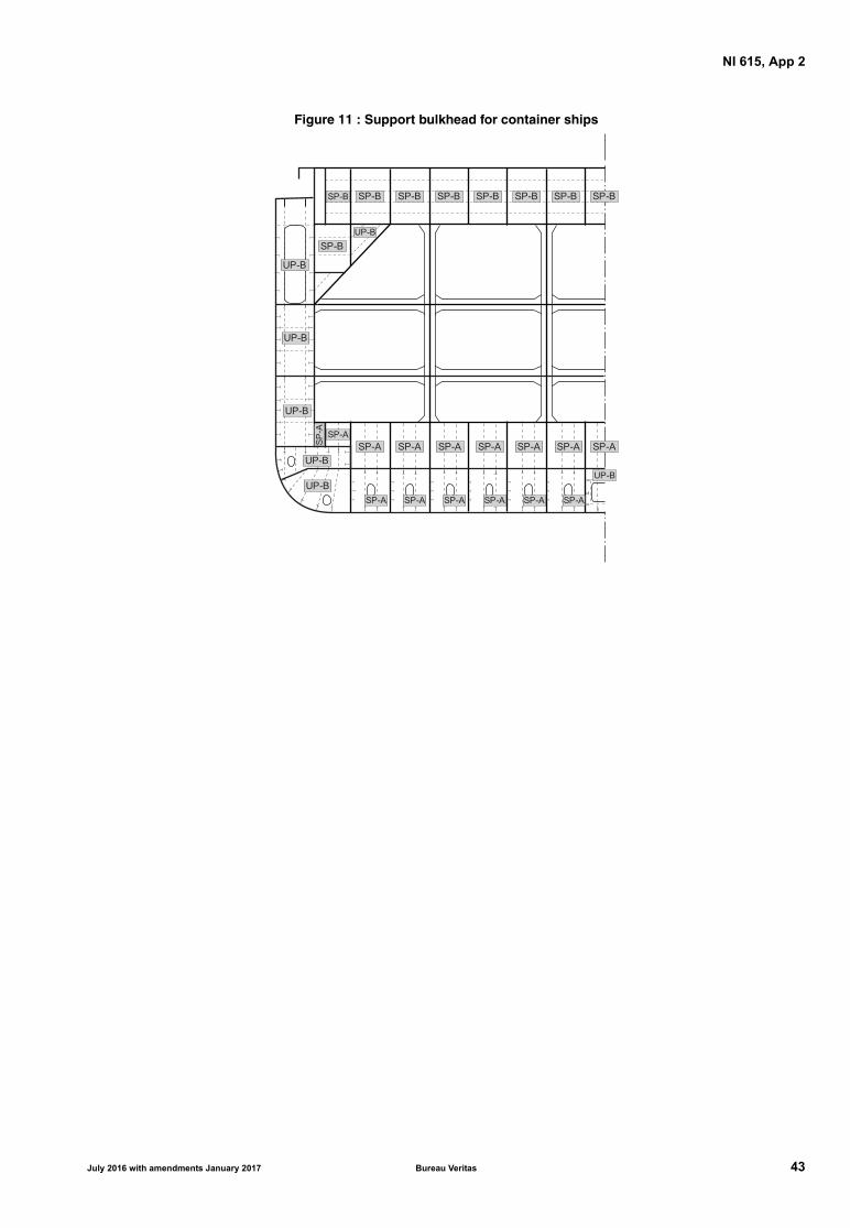
NI 615, App 2
Figure 11 : Support bulkhead for container ships
UP-B
UP-B
UP-B
UP-B
SP-A SP-A SP-ASP-ASP-A SP-A
UP-B
SP-A
SP-A SP-A SP-A SP-A SP-A SP-A
SP-B SP-B SP-B SP-B SP-B SP-B SP-BSP-B
SP-A
UP-B
SP-B
UP-B
SP
-A
July 2016 with amendments January 2017 Bureau Veritas 43

NI 615, App 2
44 Bureau Veritas July 2016 with amendments January 2017