Buckle Seismic Isolation - Buffalo · · 2011-10-11Seismic Isolation Technology forSeismic...
78
Seismic Isolation Technology for Seismic Isolation Technology for Highway Bridges _____________ Ian Buckle Foundation Professor Department of Civil and Environmental Engineering 1 University of Nevada Reno, Reno NV 89557
Transcript of Buckle Seismic Isolation - Buffalo · · 2011-10-11Seismic Isolation Technology forSeismic...

Seismic Isolation Technology forSeismic Isolation Technology for Highway Bridges
_____________
Ian Buckle
Foundation Professor
Department of Civil and Environmental Engineering
1
University of Nevada Reno, Reno NV 89557

Topics• Background• Principles of Seismic Isolation• Some Applications• System Design• Testing Requirements
Sources:• FHWA/MCEER 2006, Seismic
I l ti f Hi h B id S i lIsolation of Highway Bridges, SpecialPublication MCEER-06-SP07
• AASHTO 2010 Guide Specifications for
2
• AASHTO 2010, Guide Specifications for Seismic Isolation Design, Third Edition

Topics
• BackgroundBackground• Principles of Seismic Isolation
S A li ti• Some Applications• System Design• Testing Requirements
3

Conventional Seismic Design
Superstructure
Ab t tBearingsAbutment Abutment
ea gsAbutment
Footing & piles
Columns are required to support
4
Columns are required to support gravity and earthquake loads, dissipate energy, and not collapse
EQ ground motion

Unacceptable Performance
Collapsed Superstructure
Ab t tBearings
Ab t t
Fractured Column
Abutmentea gs
Abutment
Piles
ColumnFooting
Piles
5
EQ ground motion

Seismic Design Objective
column strengthF t f f t 1 0Factor of safety =
earthquake force> 1.0
6

Seismic Design Objective
capacityF t f f t 1 0Factor of safety = > 1.0
demand
7

Conventional Design ApproachINCREASE CAPACITY
capacityF t f f t 1 0Factor of safety = > 1.0
demand
8

Conventional Design
9

Conventional Design
10

Seismic Isolation… an Alternative
capacityF t f f t 1 0Factor of safety = > 1.0
demand
REDUCE DEMAND
11

Seismic Isolation… an Alternative
12

Seismic Isolation… an Alternative
IsolationIsolation ‘suspension’ system
13
EQ ground motion

Basic Idea of Seismic IsolationIsolate the bridge from ground motion by:
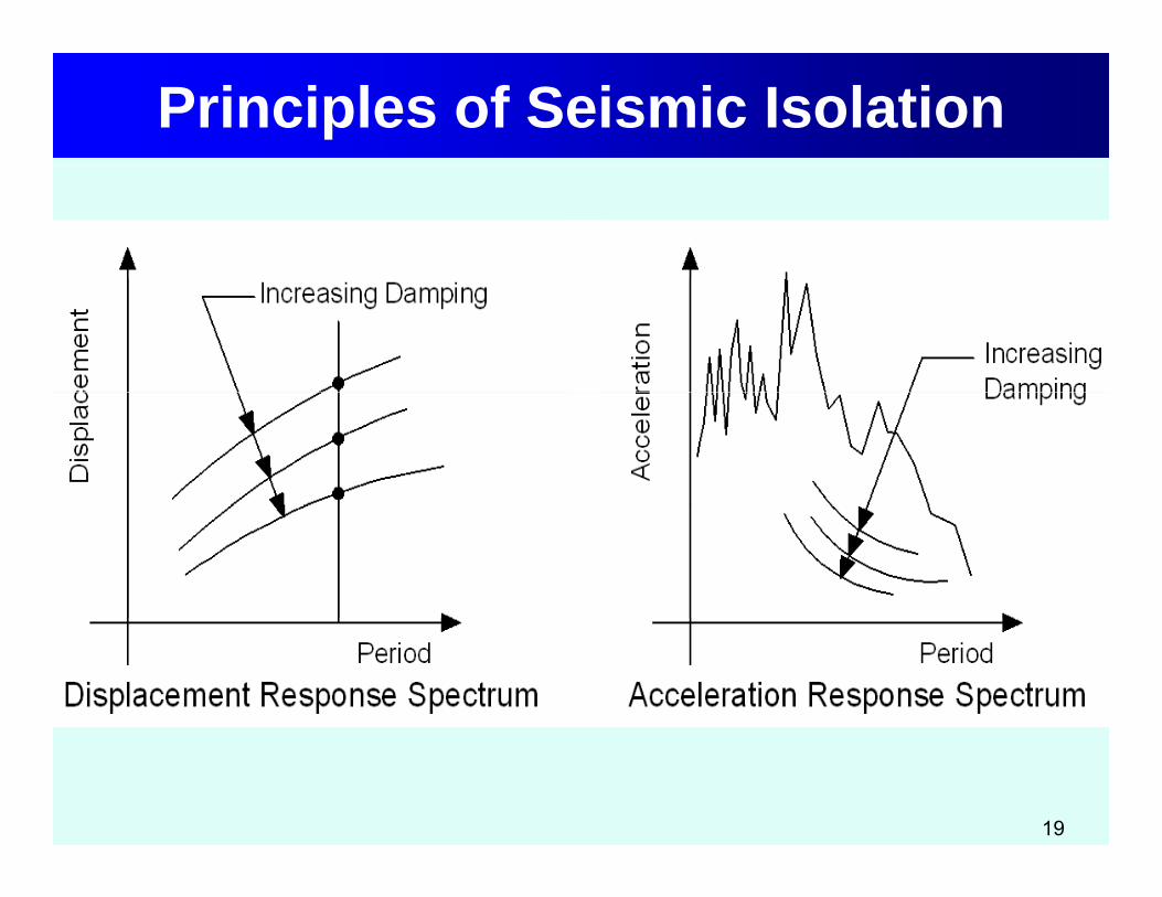
– Inserting a flexible support system between the super- and sub-structure (isolation bearings). This will lengthen the natural period of the bridge such that the inertia forces in the bridgebridge such that the inertia forces in the bridge are significantly reduced.Force reduction may be sufficient to keepForce reduction may be sufficient to keep columns elastic.
– Control the ‘liveliness’ of the bridge (due to the flexible bearings) using energy dissipators(dampers) to limit the motion
14
(dampers) to limit the motion.

Seismic Isolation: Key Point
Seismic isolation reduces the earthquakedemand on a bridge, rather than increasesgits capacity.
In many cases the reduction in demand is such that it may be feasible to have substructures perform elastically.
15

Topics
• BackgroundBackground• Principles of Seismic Isolation
S A li ti• Some Applications• System Design• Testing Requirements
16

Principles of Seismic Isolation
17

Principles of Seismic Isolation
18
Principles of Seismic Isolation
19

Principles of Seismic Isolation
20

Principles of Seismic IsolationIn addition to flexibility and energy dissipation
most isolation systems also comprise:y p• Adequate rigidity for non-seismic loads
(e g wind and braking) while(e.g. wind and braking) while accommodating thermal, creep, and other shortening effects andshortening effects, and
• Self-centering capability
21

Seismic Isolation: Key Point
Most seismic isolation systems comprise:1.Flexibility 2.Energy dissipation3.Rigidity for non-seismic loads g y4.Self-centering
Above criteria means all isolation systems have nonlinear properties…. exceptions exist
22
p p pbut are rare.

Principles of Seismic Isolation
Isolator Force, F
Kd
Kisol
Qd
Fy Fisol
Ku
dy Ku
disol Isolator Displacement, d Ku
K = Elastic (unloading) stiffness
Kd
Qd = Characteristic strength
23
Ku Elastic (unloading) stiffnessKisol = Effective stiffnessdisol = Isolator lateral displacement
d gFy = Yield strengthFisol = Isolator lateral forceKd = Post-elastic stiffness

Principles of Seismic Isolation
POLISHED STAINLESS STEEL SURFACEPOLISHED STAINLESS STEEL SURFACE
SEAL
R
SEAL
R
Lead-Rubber Isolator
STAINLESS STEELARTICULATED SLIDER(ROTATIONAL PART)
COMPOSITE LINER MATERIAL
RSTAINLESS STEELARTICULATED SLIDER(ROTATIONAL PART)
COMPOSITE LINER MATERIAL
R
Friction-Pendulum
24
Friction-Pendulum Isolator

Principles of Seismic Isolation
Eradiquake Isolator
25

Bridges Not Suitable for Isolation• Bridges on soft sites, because lengthening
the period may increase, rather than p y ,decrease, spectral accelerations
Soft soilSoft soil spectrumRock
spectrum
26

Bridges Not Suitable for Isolation
• Bridges in high seismic zones on soft sites, g g ,where displacements may be large and costly expansion joints may be required to accommodate movements
• Bridges with tall flexible piers, which already have long periods and little advantage is
i d ith i l tigained with isolation
27

Seismic Isolation: Key Point
Bridges that are most suitable for isolation are (a) located on stiff and medium-stiff soil
sites, (b) have relatively stiff substructures
(e.g. short-to-medium height columns)(c) continuous superstructures, and (d) seat-type abutments.
28

Topics
• BackgroundBackground• Principles of Seismic Isolation
S A li ti• Some Applications• System Design• Testing Requirements
29

Applications: So. Rangitikei River, NZ
30

Applications: US 101 Sierra Point, CA
31

Applications: I-680 Benecia-Martinez, CAMartinez, CA
32

Applications: JFK Airport Light Rail, NY
33

Applications: Bolu Viaduct, Turkey
34

Applications in U.S, Canada, Mexico
Applications(Percent of total
Isolator Type
(Percent of total number of
isolated bridges in Northin North
America)
Lead rubber isolator 75%Lead-rubber isolator 75%
Eradiquake isolator 20%
Other: Friction pendulum, High damping rubber, Natural Rubber FIP isolator
5%
35
Rubber, FIP isolator

Topics
• BackgroundBackground• Principles of Seismic Isolation
S A li ti• Some Applications• System Design• Testing Requirements
36

Design of a Bridge Isolation SystemThree step process:
1. Determine required performance criteriae e e equ ed pe o a ce c e a2. Determine properties of the isolation system
(e.g. Qd and Kd) to achieve required ( g d d) qperformance using one or more methods of analysis V Kd
3. Select isolator type and design hardware to achieve
V KdQd
required system properties (i.e.,Qd and Kd values) using
D
37
d d
a rational design procedure

Performance Criteria• Usually set by owner• Examples include:Examples include:
o Not-to-exceed total base shear for Design Earthquake (DE)Earthquake (DE)
o Elastic columns during DEo Not-to-exceed longitudinal displacement ino Not to exceed longitudinal displacement in
superstructure during DE.o Essentially elastic behavior for the Maximumo Essentially elastic behavior for the Maximum
Considered Earthquake (MCE)o Reparable damage in MCE, but not collapse
38
p g , p

Analysis Methods for Isolated BridgesBridges
Bridges with nonlinear isolators may beBridges with nonlinear isolators may be analyzed using linear methods provided equivalent properties are used such asequivalent properties are used, such as • effective stiffness and
i l t i d i b d• equivalent viscous damping based on the hysteretic energy dissipated by the i l tisolators.
39

Analysis Methods
• Simplified MethodSimplified Method• Single Mode Spectral Method
M lti d S t l M th d• Multimode Spectral Method • Time History Method
40

Simplified Method Assumptions1. Superstructure acts a rigid-diaphragm compared
to flexibility of isolators2 Single displacement describes motion of2. Single displacement describes motion of
superstructure, i.e. single degree-of-freedom systemy
3. Nonlinear properties of isolators may be represented by bilinear loops
V4. Bilinear loops can be represented by Kisol,
ff i iff d
V
effective stiffness, and energy dissipated per cycle
f l
Kisol D
41
= area of loop Note Kisol & loop area are dependent on displacement, D.

Simplified Method Assumptions5. Energy dissipated per cycle may be
represented by viscous damping, i.e., work done during plastic deformation can be represented by work done moving viscous fluid through an orifice Equivalent viscousfluid through an orifice. Equivalent viscous damping ratio given by
)1(2
isol
y
isol
d
dd
FQh
6. Acceleration spectrum is inversely i l i d (S / T)
42
proportional to period (SA = a / T)

Simplified Method Assumptions7. Acceleration spectra for 5% viscous
damping may be scaled for actual damping (h%) by dividing by a damping coefficient, BL
3.0
050
hBL 05.0
B is used in long period range of spectrumBL is used in long-period range of spectrum. A second factor (BS) is used in short-period range Isolated bridges fall in long period
43
range. Isolated bridges fall in long-period range.

AASHTO Design Response SpectraAASHTO Spectra (SA) are for 5% damping on a rock site (Site Class B)
SA (A) Spectral Acceleration (g)
5 % damping B)
For sites other than rock, the spectra are modified by Site SD1
h % damping p yFactors, Fa and Fv
For damping other than 5%, the Period T1.0s
SD1 / BL
spectra are modified by a Damping Factor, BL
SSFAS Dv 11
Period, T
SD (D) Spectral Displacement
5 % damping
TBS
TBSAS
L
D
L
vA
11
TSTSFg
≈10SD1
5 % damping
44
L
D
L
vD B
TSB
TSFgDS 112 79.9
4
Period, T1.0s
h % damping≈10SD1 / BL

Simplified MethodV
This method is alsoV
FisolQdKd
known as the Direct-Displacement
Kisol DDirect Displacement Method
d i li bl t
disol
S (D) Spectraland is applicable toa wide range of
SD (D) Spectral Displacement
10S
5 % damping
structural types - not just isolated bridges.
≈10SD1
h % damping≈10SD1 / BL
45
just isolated bridges.Period, T1.0s
p g10SD1 / BL

Simplified MethodBasic steps:1. Assume value for
VFisolQd
Kdisol
2. Calculate effective KisolD
Kd
stiffness, Kisol
3. Calculate max. force,
Ddisol
Fisol
4. Calculate effective i d Tperiod, Teff
d KQK isoldKF ffWT 2
46
disol
isol Kd
K isolisolisol dKF isol
eff gKT 2

Simplified Method Continued5. Calculate viscous
damping ratio, hV
FisolQdK6. Calculate damping
coefficient, BL KisolD
Kd
7. Calculate disol
8. Compare with value
Ddisoldy
for disol in Step (1). Repeat if necessary until convergence
effL
visol T
BSFgd 1
24
until convergence.
)1(2 yd
dd
FQh 3.0)
050( hBL )(79.9 1 inchesT
BSFd eff
visol
47
isolisol dF )05.0
(L B ffL

Example: Simplified Method
The superstructure of a 2-span bridge weighs533 K It is located on a rock site where S =533 K. It is located on a rock site where SD1 = 0.55. The bridge is seismically isolated with 12 isolation bearings at the piers and12 isolation bearings at the piers and abutments.
Isolation
system
48

Example
If the value of Q = 0 075W andIf the value of Qd = 0.075W and Kd = 13.0 K/in (summed over all theisolators), calculate the maximumdisplacement of the superstructure and thetotal base shear.
Neglect pier flexibility.
49

Example 1Solution:1. Initialize
1.1 Qd =0.075 W = 0.075 (533) = 40 K1 2 Need initial value di l1.2 Need initial value disol
Take Teff = 1.5 sec, 5% damping (B =1 0) and calculate5% damping (BL=1.0) and calculate D = 9.79 SD1 Teff / BL
9 79 (0 55) 1 5= 9.79 (0.55) 1.5 = 8.08 in
50
Take initial value for disol = D

Example 1 ContinuedSolution:1. Initialize
Qd = 40 KD = 8 08 inD 8.08 in
2 Iterate2. Iterate2.1 Set disol = D and proceed with Steps 1-7
51

Example 1 ContinuedStep Trial 1 Trial 2 Trial n0. Characteristic strength, Qd 40.00. Post-elastic stiffness, Kd 13.01. Isolator Displacement, disol
2. Effective stiffness, Kisol
3. Max. isolator force, Fm
4. Effective period, Teff
5. Viscous damping ratio, h%6 D i ffi i t B6. Damping coefficient, BL
7. Isolator displacement, disol
52

Example 1 ContinuedStep Trial 1 Trial 2 Trial n0. Characteristic strength, Qd 40.00. Post-elastic stiffness, Kd 13.01. Isolator Displacement, disol 8.082. Effective stiffness, Kisol
3. Max. isolator force, Fm
4. Effective period, Teff
5. Viscous damping ratio, h%6 D i ffi i t B6. Damping coefficient, BL
7. Isolator displacement, disol
53

Example 1 ContinuedStep Trial 1 Trial 2 Trial n0. Characteristic strength, Qd 40.00. Post-elastic stiffness, Kd 13.01. Isolator Displacement, disol 8.082. Effective stiffness, Kisol 17.953. Max. isolator force, Fm
4. Effective period, Teff
5. Viscous damping ratio, h%6 D i ffi i t B6. Damping coefficient, BL
7. Isolator displacement, disol
54

Example 1 ContinuedStep Trial 1 Trial 2 Trial n0. Characteristic strength, Qd 40.00. Post-elastic stiffness, Kd 13.01. Isolator Displacement, disol 8.082. Effective stiffness, Kisol 17.953. Max. isolator force, Fm 144.94. Effective period, Teff
5. Viscous damping ratio, h%6 D i ffi i t B6. Damping coefficient, BL
7. Isolator displacement, disol
55

Example 1 ContinuedStep Trial 1 Trial 2 Trial n0. Characteristic strength, Qd 40.00. Post-elastic stiffness, Kd 13.01. Isolator Displacement, disol 8.082. Effective stiffness, Kisol 17.953. Max. isolator force, Fm 144.94. Effective period, Teff 1.465. Viscous damping ratio, h%6 D i ffi i t B6. Damping coefficient, BL
7. Isolator displacement, disol
56

Example 1 ContinuedStep Trial 1 Trial 2 Trial n0. Characteristic strength, Qd 40.00. Post-elastic stiffness, Kd 13.01. Isolator Displacement, disol 8.082. Effective stiffness, Kisol 17.953. Max. isolator force, Fm 144.94. Effective period, Teff 1.465. Viscous damping ratio, h% 17.66 D i ffi i t B6. Damping coefficient, BL
7. Isolator displacement, disol
57

Example 1 ContinuedStep Trial 1 Trial 2 Trial n0. Characteristic strength, Qd 40.00. Post-elastic stiffness, Kd 13.01. Isolator Displacement, disol 8.082. Effective stiffness, Kisol 17.953. Max. isolator force, Fm 144.94. Effective period, Teff 1.465. Viscous damping ratio, h% 17.66 D i ffi i t B 1 466. Damping coefficient, BL 1.467. Isolator displacement, disol
58

Example 1 ContinuedStep Trial 1 Trial 2 Trial n0. Characteristic strength, Qd 40.00. Post-elastic stiffness, Kd 13.01. Isolator Displacement, disol 8.082. Effective stiffness, Kisol 17.953. Max. isolator force, Fm 144.94. Effective period, Teff 1.465. Viscous damping ratio, h% 17.66 D i ffi i t B 1 466. Damping coefficient, BL 1.467. Isolator displacement, disol 6.43
59

Example 1 ContinuedStep Trial 1 Trial 2 Trial n0. Characteristic strength, Qd 40.0 40.00. Post-elastic stiffness, Kd 13.0 13.01. Isolator Displacement, disol 8.08 6.432. Effective stiffness, Kisol 17.953. Max. isolator force, Fm 144.94. Effective period, Teff 1.465. Viscous damping ratio, h% 17.66 D i ffi i t B 1 466. Damping coefficient, BL 1.467. Isolator displacement, disol 6.43
60

Example 1 ContinuedStep Trial 1 Trial 2 Trial n0. Characteristic strength, Qd 40.0 40.0 40.00. Post-elastic stiffness, Kd 13.0 13.0 13.01. Isolator Displacement, disol 8.08 6.43 5.662. Effective stiffness, Kisol 17.95 20.063. Max. isolator force, Fm 144.9 113.64. Effective period, Teff 1.46 1.655. Viscous damping ratio, h% 17.6 22.46 D i ffi i t B 1 46 1 576. Damping coefficient, BL 1.46 1.577. Isolator displacement, disol 6.43 5.66
61

Example 1 ContinuedStep Trial 1 Trial 2 Trial n0. Characteristic strength, Qd 40.0 40.0 40.00. Post-elastic stiffness, Kd 13.0 13.0 13.01. Isolator Displacement, disol 8.08 6.43 5.662. Effective stiffness, Kisol 17.95 20.063. Max. isolator force, Fm 144.9 113.64. Effective period, Teff 1.46 1.655. Viscous damping ratio, h% 17.6 22.46 D i ffi i t B 1 46 1 576. Damping coefficient, BL 1.46 1.577. Isolator displacement, disol 6.43 5.66
62

Simplified MethodF
• Basic method assumes very
Kd
Qd
F
Kisol
ystiff piers but method can
dy disol
F
Superstructure Isolator Effective Stiffness, Kisol
be modifiedto include dsub
Ksub
Substructure, Ksub
Isolator(s), Kisol
pier flexibility. sub
Fdisol dsub
Substructure Stiffness, Ksub
Keff d
63MCEER,2006.
d = disol + dsub
Combined Effective Stiffness, Keff

Multimodal Spectral Method• Elastic Multimodal Method, developed for
conventional bridges, may be used for isolated bridges even though they are nonlinear systems.
Modeling the nonlinear properties of the isolators is usually done with equivalent linearized springs and the response spectrum is modified for theand the response spectrum is modified for the additional damping in the ‘isolated modes’in the isolated modes .Recall earlier discussionof the ‘composite’ spectrum
64
p p

Multimodal Spectral Method
• Method is iterative and a good strategy is toMethod is iterative and a good strategy is to use the results from the Simplified Method of Analysis to obtain starting values for theAnalysis to obtain starting values for the iteration.
• In this case convergence in 1 or 2 cycles is ibl llpossible… usually
65

Isolator Design• Analysis gives required system properties
(Qd and Kd) to meet desired performance( d d) p• Next step is to design an isolation system to
have these propertieshave these properties• Isolators used in bridge design include:
Elastomeric bearings with lead cores (Lead• Elastomeric bearings with lead cores (Lead-Rubber Bearing)
• Curved sliders (Friction Pendulum System)• Curved sliders (Friction Pendulum System)• Flat plate slider with elastomeric spring
dampers (Eradiquake System)
66
dampers (Eradiquake System)

Elastomeric Isolator Design (LRB)
67

Elastomeric Isolator Design (LRB)• Qd = 0.9 d2 (K)
where d = diameter of lead core (in)
• K = G A / T• Kd = G Ar / Trwhere G = shear modulus of elastomer (e g 0 1 Ksi)G = shear modulus of elastomer (e.g. 0.1 Ksi)Ar = bonded area of elastomerT = total thickness of elastomerTr total thickness of elastomer
• Period (post-yield) =
g
TGgK
WT rcd
2)(2
68
Period (post yield)
gGgKd
d )(

Curved Sliding Isolators (FPS)
R
W
Restoring force
Friction
g
69
D(Displacement)

Curved Sliding Isolator Design (FPS)POLISHED STAINLESS STEEL SURFACEPOLISHED STAINLESS STEEL SURFACE
• Qd = Wwhere SEALSEAL
= coefficient of frictionW = weight per isolator
STAINLESS STEELARTICULATED SLIDER(ROTATIONAL PART)
COMPOSITE LINER MATERIAL
SEAL
RSTAINLESS STEELARTICULATED SLIDER(ROTATIONAL PART)
COMPOSITE LINER MATERIAL
SEAL
R
W weight per isolator
• K =
( )( )
W• Kd = whereR di f t f lid
RW
R=radius of curvature of slider
R270
• Period when sliding = gRTd 2

Summary of LRB and FPS Designs
El t i C d SlidElastomeric (LRB)
Curved Slider(FPS)
Number of isolators 12 12
External dimensions9.4 in diam. 18 in diam.
External dimensionsx 7.75 in height x 5 in (est.) height
Internal dimensions 11 x ½ in layers radius = 41 in
Other 1.92 in diam. lead core
coefficient of friction = 0.075
71

Eradiquake Isolator
72

Other Design Issues (All) • Restoring force capability• Clearances (expansion joints, utility crossings… )( p j y g )• Vertical load capacity and stability at high shear
strain• Uplift restrainers, tensile capacity• Non-seismic requirements (wind, braking, thermal q ( g
movements… )• System Property Modification Factors (-factors) for
aging, temperature, wear and tear, and contamination
73

Topics
• Background• Principles of Seismic Isolation, • Some Applicationspp• System Design• Testing Requirements• Testing Requirements
74

Basic Testing Requirements• Because isolators are subject to extreme
deformations and loads during large g gearthquakes, most design codes require they be tested to demonstrate conformance with design expectations
• For both reasons (extreme loads andFor both reasons (extreme loads and extensive testing), design provisions for isolation bearings may differ from that forisolation bearings may differ from that for conventional bearings e.g., Section 14, AASHTO LRFD Design Specifications
75
AASHTO LRFD Design Specifications

Basic Testing RequirementsUsually three categories of tests are required:
1. Characterization Tests to confirm basic C a acte at o ests o co bas cproperties such as effect of velocity, pressure, and temperature to develop models for analysis
2. Prototype Tests for each project prior to production to confirm mechanical properties used in design
3. Production Tests performed on each isolator ( l ith t i l t t ) f lit(along with material tests) for quality control/quality assurance.
76

During this lecture we have learned:• Basic purpose of seismic isolation • Four components of an isolation systemFour components of an isolation system• Bridge types / configurations suitable for
seismic isolationseismic isolation• How to calculate displacement and base
shear in an isolated bridge using theshear in an isolated bridge using the Simplified Method
• About three kinds of isolators in use today

Five questions
1. What is basic purpose of seismic isolation? 2 List the four components of an isolation system2. List the four components of an isolation system.3. Describe bridge types and configurations that
are suitable for seismic isolation.are suitable for seismic isolation.4. Name three common types of isolators on the
market today in the U.S. y5. Name three types of tests used to assure the
quality of seismic isolatorsquality of seismic isolators