BTS3900A (Ver.D) Installation Guide(V100R009C00_01)(PDF)-En
281
BTS3900A(Ver.D) V100R009C00 Installation Guide Issue 01 Date 2014-04-30 HUAWEI TECHNOLOGIES CO., LTD.
description
hauwei BTS 3900A installation
Transcript of BTS3900A (Ver.D) Installation Guide(V100R009C00_01)(PDF)-En
BTS3900A(Ver.D)
V100R009C00
Installation Guide
Issue 01
Date 2014-04-30
HUAWEI TECHNOLOGIES CO., LTD.

Copyright © Huawei Technologies Co., Ltd. 2014. All rights reserved.
No part of this document may be reproduced or transmitted in any form or by any means without prior writtenconsent of Huawei Technologies Co., Ltd. Trademarks and Permissions
and other Huawei trademarks are trademarks of Huawei Technologies Co., Ltd.All other trademarks and trade names mentioned in this document are the property of their respective holders. NoticeThe purchased products, services and features are stipulated by the contract made between Huawei and thecustomer. All or part of the products, services and features described in this document may not be within thepurchase scope or the usage scope. Unless otherwise specified in the contract, all statements, information,and recommendations in this document are provided "AS IS" without warranties, guarantees or representationsof any kind, either express or implied.
The information in this document is subject to change without notice. Every effort has been made in thepreparation of this document to ensure accuracy of the contents, but all statements, information, andrecommendations in this document do not constitute a warranty of any kind, express or implied.
Huawei Technologies Co., Ltd.Address: Huawei Industrial Base
Bantian, LonggangShenzhen 518129People's Republic of China
Website: http://www.huawei.com
Email: [email protected]
Issue 01 (2014-04-30) Huawei Proprietary and ConfidentialCopyright © Huawei Technologies Co., Ltd.
i

About This Document
OverviewThis document describes the procedure for installing the cabinets, boards, modules, and cablesin the BTS3900A (Ver.D) (shortened to BTS3900A in this document). It also provides checklistsfor hardware installation.
Product VersionThe following table lists the product versions related to this document.
Product Name Product Version
BTS3900A V100R009C00The mapping single-mode base station versionsare:GBTS: V100R016C00eGBTS: V100R016C00NodeB: V200R016C00eNodeB: V100R007C00
Intended AudienceThis document is intended for:
l Base station installation engineers
Organization1 Changes in BTS3900A (Ver.D) Installation Guide
This section describes the changes in BTS3900A (Ver.D) Installation Guide.
2 Overview
BTS3900A(Ver.D)Installation Guide About This Document
Issue 01 (2014-04-30) Huawei Proprietary and ConfidentialCopyright © Huawei Technologies Co., Ltd.
ii
Familiarize yourself with this information as well as the cabinet interior, application scenariosof the cabinets, and relevant clearance requirements before installing the cabinets.
3 Installation Preparations
This chapter lists the tools and instruments that must be obtained before the installation. It alsospecifies the skills that the onsite personnel must have.
4 Unpacking Check
Unpack and check the delivered equipment to ensure that all the materials are included and intact.
5 Obtaining the ESN
The electronic serial number (ESN) is a unique identifier of a NE. Record the ESN of the basestation before the installation for future commissioning.
6 Installation Process
The process of installing the BTS3900A consists of the following procedures: installing thebases, installing the cabinets, installing optional modules, installing cables, installation check,power-on check, and subsequent operations.
7 Checking the Installed Modules and Cables
After installing modules and cables in the cabinet, you need to check that the modules and cablesare installed securely.
8 Installing the Base
This section describes the procedure and precautions for installing the base for a cabinet on aconcrete floor.
9 Installing the Cabinet
When installing the BTS3900A, use different installation modes based on different scenarios.
10 Installing a PGND Cable and an Equipotential Cable
A PGND cable connects a PGND screw in a cabinet and a PGND bar to ensure proper groundingof the cabinet. An equipotential cable connects PGND screws on different cabinets to ensure theequipotential bonding between the cabinets.
11 Installing Optional Modules and Their Cables
This chapter describes procedures for installing the optional modules and their cables onsite.
12 Installing Cables
Before cabinets used in the BTS3900A are delivered, the boards and cables inside the cabinetshave been installed. You must install the external cables and cables for optional componentsonsite.
13 Installation Checklist
After the cabinets and devices are installed, you need to check the installation items, installationenvironment, and cable-related items.
14 Powering On a Base Station
BTS3900A(Ver.D)Installation Guide About This Document
Issue 01 (2014-04-30) Huawei Proprietary and ConfidentialCopyright © Huawei Technologies Co., Ltd.
iii

This section describes how to power on a base station and handle a failure in the power supplyto the components in a cabinet.
15 Subsequent Operations
This chapter describes the operations that need to be performed after the installation, whichinclude sealing the cable holes on the base of the cabinet and repainting the cabinet.
ConventionsSymbol Conventions
The symbols that may be found in this document are defined as follows.
Symbol Description
Indicates an imminently hazardous situation which, if notavoided, will result in death or serious injury.
Indicates a potentially hazardous situation which, if notavoided, could result in death or serious injury.
Indicates a potentially hazardous situation which, if notavoided, may result in minor or moderate injury.
Indicates a potentially hazardous situation which, if notavoided, could result in equipment damage, data loss,performance deterioration, or unanticipated results.NOTICE is used to address practices not related to personalinjury.
Calls attention to important information, best practices andtips.NOTE is used to address information not related to personalinjury, equipment damage, and environment deterioration.
General Conventions
The general conventions that may be found in this document are defined as follows.
Convention Description
Times New Roman Normal paragraphs are in Times New Roman.
Boldface Names of files, directories, folders, and users are inboldface. For example, log in as user root.
Italic Book titles are in italics.
BTS3900A(Ver.D)Installation Guide About This Document
Issue 01 (2014-04-30) Huawei Proprietary and ConfidentialCopyright © Huawei Technologies Co., Ltd.
iv

Convention Description
Courier New Examples of information displayed on the screen are inCourier New.
Command Conventions
The command conventions that may be found in this document are defined as follows.
Convention Description
Boldface The keywords of a command line are in boldface.
Italic Command arguments are in italics.
[ ] Items (keywords or arguments) in brackets [ ] are optional.
{ x | y | ... } Optional items are grouped in braces and separated byvertical bars. One item is selected.
[ x | y | ... ] Optional items are grouped in brackets and separated byvertical bars. One item is selected or no item is selected.
{ x | y | ... }* Optional items are grouped in braces and separated byvertical bars. A minimum of one item or a maximum of allitems can be selected.
[ x | y | ... ]* Optional items are grouped in brackets and separated byvertical bars. Several items or no item can be selected.
GUI Conventions
The GUI conventions that may be found in this document are defined as follows.
Convention Description
Boldface Buttons, menus, parameters, tabs, window, and dialog titlesare in boldface. For example, click OK.
> Multi-level menus are in boldface and separated by the ">"signs. For example, choose File > Create > Folder.
Keyboard Operations
The keyboard operations that may be found in this document are defined as follows.
Format Description
Key Press the key. For example, press Enter and press Tab.
BTS3900A(Ver.D)Installation Guide About This Document
Issue 01 (2014-04-30) Huawei Proprietary and ConfidentialCopyright © Huawei Technologies Co., Ltd.
v
Format Description
Key 1+Key 2 Press the keys concurrently. For example, pressing Ctrl+Alt+A means the three keys should be pressed concurrently.
Key 1, Key 2 Press the keys in turn. For example, pressing Alt, A meansthe two keys should be pressed in turn.
Mouse Operations
The mouse operations that may be found in this document are defined as follows.
Action Description
Click Select and release the primary mouse button without movingthe pointer.
Double-click Press the primary mouse button twice continuously andquickly without moving the pointer.
Drag Press and hold the primary mouse button and move thepointer to a certain position.
BTS3900A(Ver.D)Installation Guide About This Document
Issue 01 (2014-04-30) Huawei Proprietary and ConfidentialCopyright © Huawei Technologies Co., Ltd.
vi
Contents
About This Document.....................................................................................................................ii
1 Changes in BTS3900A (Ver.D) Installation Guide.................................................................1
2 Overview.........................................................................................................................................32.1 Cabinet Interior...............................................................................................................................................................42.2 BTS3900A (Ver.D) Configured with RFUs but Without RRUs..................................................................................182.3 BTS3900A (Ver.D) Configured with RFUs and RRUs...............................................................................................302.4 Installation Clearance Requirements............................................................................................................................392.5 Engineering Specifications of Customer Equipment in the APM30H.........................................................................40
3 Installation Preparations............................................................................................................453.1 Document Preparations.................................................................................................................................................463.2 Tools and Instruments..................................................................................................................................................463.3 Requirements for Onsite Personnel..............................................................................................................................47
4 Unpacking Check........................................................................................................................48
5 Obtaining the ESN......................................................................................................................50
6 Installation Process.....................................................................................................................52
7 Checking the Installed Modules and Cables.........................................................................547.1 Checking the BTS3900A Cabinets Supplied with AC Power......................................................................................557.2 Checking the BTS3900A Cabinets Supplied with -48 V DC Power...........................................................................59
8 Installing the Base.......................................................................................................................65
9 Installing the Cabinet.................................................................................................................729.1 Installing the Cabinet on a Base...................................................................................................................................739.2 Stacking Two Cabinets.................................................................................................................................................78
10 Installing a PGND Cable and an Equipotential Cable......................................................81
11 Installing Optional Modules and Their Cables..................................................................8611.1 Installing the SLPU as a Monitoring Signal Protection Unit.....................................................................................8811.2 Installing the EMUA/EMUB and Its Cables..............................................................................................................9211.2.1 Installing the EMUA/EMUB in the APM30H........................................................................................................9211.2.2 Installing the EMUA/EMUB in the TMC11H........................................................................................................98
BTS3900A(Ver.D)Installation Guide Contents
Issue 01 (2014-04-30) Huawei Proprietary and ConfidentialCopyright © Huawei Technologies Co., Ltd.
vii

11.3 Installing the GPS Surge Protector...........................................................................................................................10411.4 Installing the GATM and Bias-Tee..........................................................................................................................10911.5 Installing the DDF....................................................................................................................................................11511.6 Installing the Batteries..............................................................................................................................................11811.7 Installing the DCDU-12B.........................................................................................................................................12111.8 Installing the BBU....................................................................................................................................................12711.9 Installing Boards in the BBU and surge protection boards......................................................................................13511.10 Installing the RFU..................................................................................................................................................13811.11 Installing the RRU..................................................................................................................................................14411.12 Installing the AC Heater.........................................................................................................................................14411.13 (Optional) Installing the HAU01A-01....................................................................................................................148
12 Installing Cables......................................................................................................................15312.1 Cabling Requirements..............................................................................................................................................15412.2 Cable Holes...............................................................................................................................................................16012.3 Installing Power Cables............................................................................................................................................16512.3.1 Installing Power Cables for AC Cabinets..............................................................................................................16512.3.2 Installing Power Cables for DC Cabinets..............................................................................................................19512.4 Installing Transmission Cables.................................................................................................................................20112.4.1 Installing the E1/T1 Cables...................................................................................................................................20112.4.2 Installing the FE/GE Ethernet Cables....................................................................................................................20312.4.3 Installing the FE/GE Fiber Optic Cables...............................................................................................................20512.5 Installing Signal Cables............................................................................................................................................20712.5.1 Installing Monitoring Signal Cables Between Cabinets in AC Scenarios.............................................................20812.5.2 Installing Monitoring Signal Cables Between Cabinets in -48 V DC Scenarios..................................................23212.5.3 (Optional) Installing Inter-BBU Signal Cables.....................................................................................................23912.5.4 Installing a BBU Alarm Cable...............................................................................................................................24312.6 Installing RF Jumpers...............................................................................................................................................24412.7 (Optional) Installing the CPRI Electrical Cables.....................................................................................................24812.8 (Optional) Installing the CPRI Fiber Optic Cables..................................................................................................250
13 Installation Checklist..............................................................................................................253
14 Powering On a Base Station..................................................................................................256
15 Subsequent Operations..........................................................................................................26615.1 Sealing the Cable Holes............................................................................................................................................26715.2 Repainting.................................................................................................................................................................270
BTS3900A(Ver.D)Installation Guide Contents
Issue 01 (2014-04-30) Huawei Proprietary and ConfidentialCopyright © Huawei Technologies Co., Ltd.
viii

1 Changes in BTS3900A (Ver.D) InstallationGuide
This section describes the changes in BTS3900A (Ver.D) Installation Guide.
01 (2014-04-30)
This is the first commercial release.
Compared with Draft B (2014-02-28), this issue does not include any changes.
Draft B (2014-02-28)
This is a draft.
Compared with issue Draft A (2014-01-20), no information is added or deleted.
Compared with issue Draft A (2014-01-20), this issue incorporates the following changes:
Topic Change Description
14 Powering On a Base Station Added descriptions of the status of theindicators for CPRI ports.
Draft A (2014-01-20)
This is a draft.
Compared with multimode base station version V100R008C00, WCDMA-NodeBV200R015C00, GSM-BTS V100R015C00, eNodeB V100R006C00, this issue is added with thefollowing topic:
l 11.4 Installing the GATM and Bias-Tee
Compared with multimode base station version V100R008C00, WCDMA-NodeBV200R015C00, GSM-BTS V100R015C00, eNodeB V100R006C00, this issue incorporates thefollowing change:
BTS3900A(Ver.D)Installation Guide 1 Changes in BTS3900A (Ver.D) Installation Guide
Issue 01 (2014-04-30) Huawei Proprietary and ConfidentialCopyright © Huawei Technologies Co., Ltd.
1

Topic Change Description
l 11.1 Installing the SLPU as aMonitoring Signal Protection Unit
l 11.5 Installing the DDFl 11.8 Installing the BBU
Added the optional steps of removing the airbaffle.
11.2 Installing the EMUA/EMUB and ItsCables and it's child topics.
l Added the optional steps of removing theair baffle.
l Added the scenario of installing theEMUB.
The whole document l Added the interconnection mode aboutUMPT + UMPT for the inter-BBU signalcable.
l Added the information of UBBP.
Compared with imultimode base station version V100R008C00, WCDMA-NodeBV200R015C00, GSM-BTS V100R015C00, eNodeB V100R006C00, no topic is deleted fromthis issue.
BTS3900A(Ver.D)Installation Guide 1 Changes in BTS3900A (Ver.D) Installation Guide
Issue 01 (2014-04-30) Huawei Proprietary and ConfidentialCopyright © Huawei Technologies Co., Ltd.
2
2 Overview
About This Chapter
Familiarize yourself with this information as well as the cabinet interior, application scenariosof the cabinets, and relevant clearance requirements before installing the cabinets.
2.1 Cabinet InteriorTo adapt to the complicated and various environments outdoors, Huawei provides multiplecabinets with different functions for the BTS3900A. The cabinets are APM30H, TMC11H, RFC,IBBS200D, IBBS200T, IBBS700D, and IBBS700T.
2.2 BTS3900A (Ver.D) Configured with RFUs but Without RRUsWhen only RFUs are configured, a BTS3900A supports different cabinet configurations in 110V AC, 220 V AC, or -48 V DC power supply scenarios.
2.3 BTS3900A (Ver.D) Configured with RFUs and RRUsWhen RFUs and RRUs are configured, a BTS3900A supports different cabinet configurationsin 110 V AC, 220 V AC, or -48 V DC power supply scenarios.
2.4 Installation Clearance RequirementsThe installation of the BTS3900A is classified into three scenarios: a single cabinet is installedalone, two cabinets are installed side by side, and two cabinets are stacked.
2.5 Engineering Specifications of Customer Equipment in the APM30HThe customer equipment to be installed in Huawei cabinets must meet the requirements forengineering specifications.
BTS3900A(Ver.D)Installation Guide 2 Overview
Issue 01 (2014-04-30) Huawei Proprietary and ConfidentialCopyright © Huawei Technologies Co., Ltd.
3
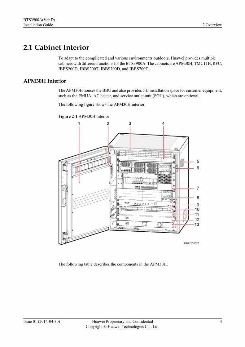
2.1 Cabinet InteriorTo adapt to the complicated and various environments outdoors, Huawei provides multiplecabinets with different functions for the BTS3900A. The cabinets are APM30H, TMC11H, RFC,IBBS200D, IBBS200T, IBBS700D, and IBBS700T.
APM30H InteriorThe APM30H houses the BBU and also provides 5 U installation space for customer equipment,such as the EMUA, AC heater, and service outlet unit (SOU), which are optional.
The following figure shows the APM30H interior.
Figure 2-1 APM30H interior
The following table describes the components in the APM30H.
BTS3900A(Ver.D)Installation Guide 2 Overview
Issue 01 (2014-04-30) Huawei Proprietary and ConfidentialCopyright © Huawei Technologies Co., Ltd.
4

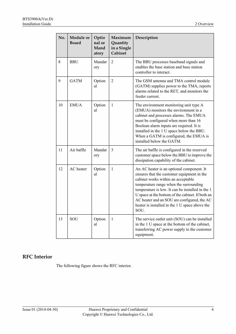
Table 2-1 Components in the APM30H
No. Module orBoard
Optional orMandatory
MaximumQuantityin a SingleCabinet
Description
1 Outer aircirculationassembly
Mandatory
1 The outer air circulation assembly includes aheat exchanger core and a fan.l The heat exchanger core promotes the
inner and outer air circulation, andexchanges internal and external air. In thisway, it lowers the operating temperature ofthe cabinet and protects the cabinet fromdust.
l The fan dissipates heat from the cabinet.
2 ACjunctionbox
Mandatory
1 When a heater or heating film is configured,the junction box provides power for the heateror heating film.
3 FAN 02D Mandatory
1 The FAN 02D is configured with fans andcentral monitoring unit type EA (CMUEA).The fans dissipate heat from the cabinet.
4 SLPU Mandatory
2 l To provide protection for trunk signals, asignal lightning protection unit (SLPU) ismandatory and installed in the top 1 Uspace of the cabinet. It is configured withthe universal E1/T1 lightning protectionunit (UELP) or universal FE lightningprotection unit (UFLP).
l To provide protection for monitoringsignals, an SLPU is optional and installedin the 1 U space below the BBU. It isconfigured with two universal signallightning protection unit 2 (USLP2)boards.
5 ELU Mandatory
1 The electronic label unit (ELU) reports thecabinet type automatically to facilitatetroubleshooting.
6 Door statussensor
Mandatory
1 The door status sensor reports the door status.
7 EPU05Asubrack
Mandatory
1 The EPU05A subrack distributes AC and DCpower for the cabinet. The EPU subracks in aseparated macro base station can be dividedinto two types which use 110 V AC power and220 V AC power, respectively.
BTS3900A(Ver.D)Installation Guide 2 Overview
Issue 01 (2014-04-30) Huawei Proprietary and ConfidentialCopyright © Huawei Technologies Co., Ltd.
5
No. Module orBoard
Optional orMandatory
MaximumQuantityin a SingleCabinet
Description
8 BBU Mandatory
2 The BBU processes baseband signals andenables the base station and base stationcontroller to interact.
9 GATM Optional
2 The GSM antenna and TMA control module(GATM) supplies power to the TMA, reportsalarms related to the RET, and monitors thefeeder current.
10 EMUA Optional
1 The environment monitoring unit type A(EMUA) monitors the environment in acabinet and processes alarms. The EMUAmust be configured when more than 16Boolean alarm inputs are required. It isinstalled in the 1 U space below the BBU.When a GATM is configured, the EMUA isinstalled below the GATM.
11 Air baffle Mandatory
3 The air baffle is configured in the reservedcustomer space below the BBU to improve thedissipation capability of the cabinet.
12 AC heater Optional
1 An AC heater is an optional component. Itensures that the customer equipment in thecabinet works within an acceptabletemperature range when the surroundingtemperature is low. It can be installed in the 1U space at the bottom of the cabinet. If both anAC heater and an SOU are configured, the ACheater is installed in the 1 U space above theSOU.
13 SOU Optional
1 The service outlet unit (SOU) can be installedin the 1 U space at the bottom of the cabinet,transferring AC power supply to the customerequipment.
RFC InteriorThe following figure shows the RFC interior.
BTS3900A(Ver.D)Installation Guide 2 Overview
Issue 01 (2014-04-30) Huawei Proprietary and ConfidentialCopyright © Huawei Technologies Co., Ltd.
6
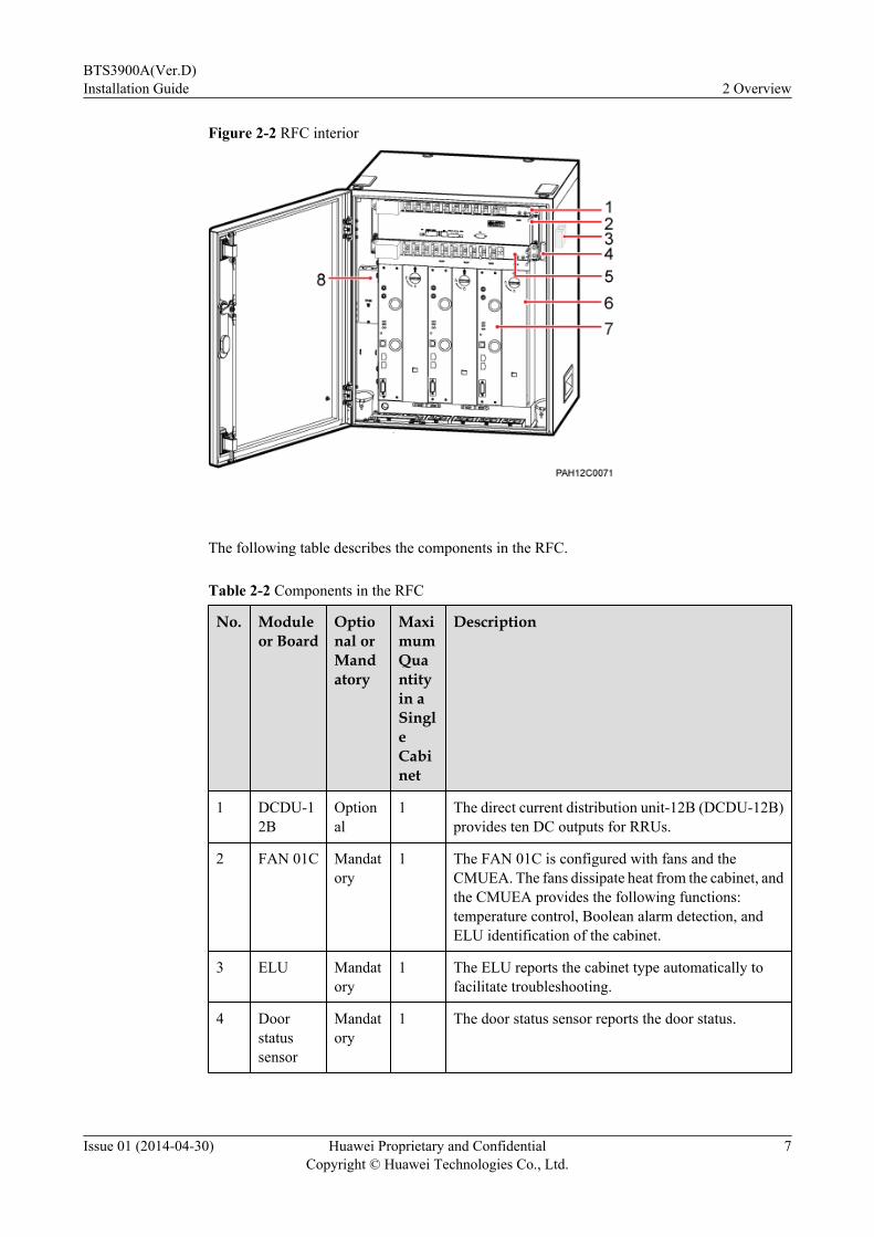
Figure 2-2 RFC interior
The following table describes the components in the RFC.
Table 2-2 Components in the RFC
No. Moduleor Board
Optional orMandatory
MaximumQuantityin aSingleCabinet
Description
1 DCDU-12B
Optional
1 The direct current distribution unit-12B (DCDU-12B)provides ten DC outputs for RRUs.
2 FAN 01C Mandatory
1 The FAN 01C is configured with fans and theCMUEA. The fans dissipate heat from the cabinet, andthe CMUEA provides the following functions:temperature control, Boolean alarm detection, andELU identification of the cabinet.
3 ELU Mandatory
1 The ELU reports the cabinet type automatically tofacilitate troubleshooting.
4 Doorstatussensor
Mandatory
1 The door status sensor reports the door status.
BTS3900A(Ver.D)Installation Guide 2 Overview
Issue 01 (2014-04-30) Huawei Proprietary and ConfidentialCopyright © Huawei Technologies Co., Ltd.
7
No. Moduleor Board
Optional orMandatory
MaximumQuantityin aSingleCabinet
Description
5 DCDU-12A
Mandatory
1 The DCDU-12A provides ten DC outputs forcomponents in the RFC.
6 Fillerpanel
Optional
- To ensure proper ventilation of the cabinet, fillerpanels must be installed in all vacant slots in the RFUsubrack.
7 RFU Mandatory
6 The radio frequency unit (RFU) is used in macro basestations. It performs the following functions:modulation and demodulation of baseband signals andRF signals, data processing, power amplification, andvoltage standing wave ratio (VSWR) detection.
8 DCjunctionbox
Mandatory
1 The DC junction box uses one or two DC power inputsand provides two DC power outputs.
TMC11H InteriorThere are two types of TMC11Hs:l One type of TMC11H houses only transmission equipment, as shown in illustration A in
the following figure.l The other type of TMC11H houses the BBU and uses the -48 V DC power supply, as shown
in illustration B in the following figure.
BTS3900A(Ver.D)Installation Guide 2 Overview
Issue 01 (2014-04-30) Huawei Proprietary and ConfidentialCopyright © Huawei Technologies Co., Ltd.
8
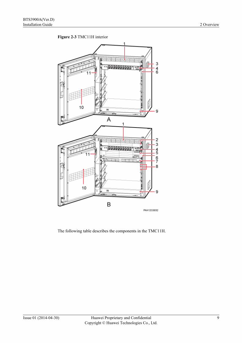
Figure 2-3 TMC11H interior
The following table describes the components in the TMC11H.
BTS3900A(Ver.D)Installation Guide 2 Overview
Issue 01 (2014-04-30) Huawei Proprietary and ConfidentialCopyright © Huawei Technologies Co., Ltd.
9
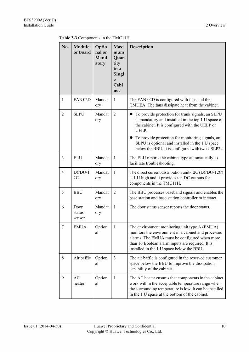
Table 2-3 Components in the TMC11H
No. Moduleor Board
Optional orMandatory
MaximumQuantityin aSingleCabinet
Description
1 FAN 02D Mandatory
1 The FAN 02D is configured with fans and theCMUEA. The fans dissipate heat from the cabinet.
2 SLPU Mandatory
2 l To provide protection for trunk signals, an SLPUis mandatory and installed in the top 1 U space ofthe cabinet. It is configured with the UELP orUFLP.
l To provide protection for monitoring signals, anSLPU is optional and installed in the 1 U spacebelow the BBU. It is configured with two USLP2s.
3 ELU Mandatory
1 The ELU reports the cabinet type automatically tofacilitate troubleshooting.
4 DCDU-12C
Mandatory
1 The direct current distribution unit-12C (DCDU-12C)is 1 U high and it provides ten DC outputs forcomponents in the TMC11H.
5 BBU Mandatory
2 The BBU processes baseband signals and enables thebase station and base station controller to interact.
6 Doorstatussensor
Mandatory
1 The door status sensor reports the door status.
7 EMUA Optional
1 The environment monitoring unit type A (EMUA)monitors the environment in a cabinet and processesalarms. The EMUA must be configured when morethan 16 Boolean alarm inputs are required. It isinstalled in the 1 U space below the BBU.
8 Air baffle Optional
3 The air baffle is configured in the reserved customerspace below the BBU to improve the dissipationcapability of the cabinet.
9 ACheater
Optional
1 The AC heater ensures that components in the cabinetwork within the acceptable temperature range whenthe surrounding temperature is low. It can be installedin the 1 U space at the bottom of the cabinet.
BTS3900A(Ver.D)Installation Guide 2 Overview
Issue 01 (2014-04-30) Huawei Proprietary and ConfidentialCopyright © Huawei Technologies Co., Ltd.
10
No. Moduleor Board
Optional orMandatory
MaximumQuantityin aSingleCabinet
Description
10 Outer aircirculationassembly
Mandatory
1 The outer air circulation assembly consists of the heatexchanger core and fans.l The heat exchanger core promotes the inner and
outer air circulation, and exchanges internal andexternal air. In this way, it lowers the operatingtemperature of the cabinet and protects the cabinetfrom dust.
l The fan dissipates heat from the cabinet.
11 ACjunctionbox
Mandatory
1 When a heater or heating film is configured, thejunction box provides power for the heater or heatingfilm.
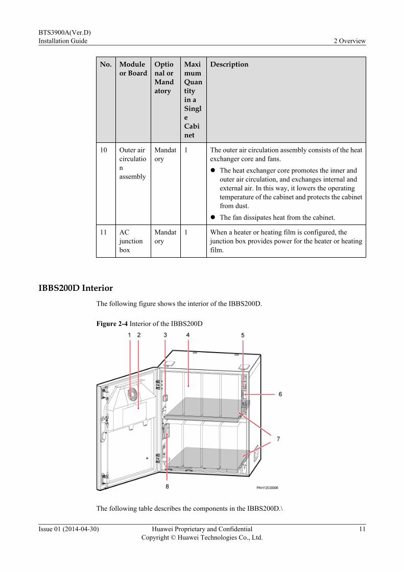
IBBS200D Interior
The following figure shows the interior of the IBBS200D.
Figure 2-4 Interior of the IBBS200D
The following table describes the components in the IBBS200D.\
BTS3900A(Ver.D)Installation Guide 2 Overview
Issue 01 (2014-04-30) Huawei Proprietary and ConfidentialCopyright © Huawei Technologies Co., Ltd.
11

Table 2-4 Components in the IBBS200D
No.
Component Optional orMandatory
MaximumQuantity inaSingleCabinet
Remarks
1 Fan mountingframe
Mandatory
1 The fan mounting frame is installed on the frontdoor of the cabinet, and configured with a fan.
2 CMUEA Mandatory
1 The central monitoring unit type EA (CMUEA)controls temperature, detects Boolean alarm, andidentifies the ELU.
3 ELU Mandatory
1 The electronic label unit (ELU) reports the cabinettype automatically to facilitate troubleshooting.
4 Storagebattery
Mandatory
8 The storage batteries provide long-durationbackup power for base stations.
5 Powerdistributionbox
Mandatory
1 The power distribution box is installed on theupper right wall of the cabinet interior. It transfersand distributes input power to the TEC or fan andstorage batteries.
6 Door statussensor
Mandatory
1 The door status sensor monitors the status (openor closed) of the cabinet door.
7 Heating film Optional
2 The IBBS200D must be configured with a heatingfilm in cold areas. The heating film is not requiredin general areas.
8 Junctionterminal forthe inputpower cable ofthe heatingfilm
Mandatory
1 The junction terminal provides the input powerport for the heating film.
IBBS200T InteriorTo improve the cooling efficiency of the TEC, the coverage of the heat insulation foam must begreater than 75% on the inner side of the IBBS200T. The following figure shows the interior ofthe IBBS200T.
BTS3900A(Ver.D)Installation Guide 2 Overview
Issue 01 (2014-04-30) Huawei Proprietary and ConfidentialCopyright © Huawei Technologies Co., Ltd.
12

Figure 2-5 Interior of the IBBS200T
The following table describes the components in the IBBS200D.
Table 2-5 Components in the IBBS200T
No.
Component
Optional orMandatory
MaximumQuantity inaSingleCabinet
Remarks
1 TEC Mandatory
1 The TEC ensures the normal operation of theIBBS200T in high-temperature areas and dissipatesheat from the storage batteries.
2 CMUEA Mandatory
1 The central monitoring unit type EA (CMUEA)controls temperature, detects Boolean alarm, andidentifies the ELU.
3 ELU Mandatory
1 The electronic label unit (ELU) reports the cabinettype automatically to facilitate troubleshooting.
4 Storagebattery
Mandatory
8 The storage batteries provide long-duration backuppower for base stations.
BTS3900A(Ver.D)Installation Guide 2 Overview
Issue 01 (2014-04-30) Huawei Proprietary and ConfidentialCopyright © Huawei Technologies Co., Ltd.
13

No.
Component
Optional orMandatory
MaximumQuantity inaSingleCabinet
Remarks
5 Powerdistribution box
Mandatory
1 The power distribution box is installed on the upperright wall of the cabinet interior. It transfers anddistributes power to the fan or TEC and storagebatteries.
6 Door statussensor
Mandatory
1 The door status sensor monitors the status (open orclosed) of the cabinet door.
IBBS700D InteriorThe following figure shows the interior of the IBBS700D.
Figure 2-6 Components of IBBS700D
The following table describes the components in the IBBS700D.
BTS3900A(Ver.D)Installation Guide 2 Overview
Issue 01 (2014-04-30) Huawei Proprietary and ConfidentialCopyright © Huawei Technologies Co., Ltd.
14
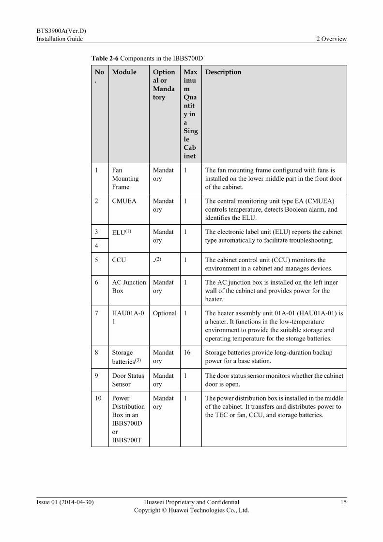
Table 2-6 Components in the IBBS700D
No.
Module Optional orMandatory
MaximumQuantity inaSingleCabinet
Description
1 FanMountingFrame
Mandatory
1 The fan mounting frame configured with fans isinstalled on the lower middle part in the front doorof the cabinet.
2 CMUEA Mandatory
1 The central monitoring unit type EA (CMUEA)controls temperature, detects Boolean alarm, andidentifies the ELU.
3 ELU(1) Mandatory
1 The electronic label unit (ELU) reports the cabinettype automatically to facilitate troubleshooting.
4
5 CCU -(2) 1 The cabinet control unit (CCU) monitors theenvironment in a cabinet and manages devices.
6 AC JunctionBox
Mandatory
1 The AC junction box is installed on the left innerwall of the cabinet and provides power for theheater.
7 HAU01A-01
Optional 1 The heater assembly unit 01A-01 (HAU01A-01) isa heater. It functions in the low-temperatureenvironment to provide the suitable storage andoperating temperature for the storage batteries.
8 Storagebatteries(3)
Mandatory
16 Storage batteries provide long-duration backuppower for a base station.
9 Door StatusSensor
Mandatory
1 The door status sensor monitors whether the cabinetdoor is open.
10 PowerDistributionBox in anIBBS700DorIBBS700T
Mandatory
1 The power distribution box is installed in the middleof the cabinet. It transfers and distributes power tothe TEC or fan, CCU, and storage batteries.
BTS3900A(Ver.D)Installation Guide 2 Overview
Issue 01 (2014-04-30) Huawei Proprietary and ConfidentialCopyright © Huawei Technologies Co., Ltd.
15

NOTE
l (1) When a CCU is configured, the ELU is installed in the position illustrated by "4." When no CCUis configured, the ELU is installed in the position illustrated by "3."
l (2) When the IBBS700D cabinet is used with an APM30H (Ver.D) cabinet, no CCU is required. Whenthe IBBS700D cabinet is used with a BTS3900AL (Ver.A) or TP48600A-H17B1 cabinet, a CCU isrequired.
l (3) The storage batteries provide current of 300 Ah, 450 Ah, or 600 Ah for a single cabinet and providecurrent of 150 Ah or 300 Ah for each one in a cabinet combination.
l A battery temperature sensor is configured in the cabinet by default. For details about the position ofthe battery temperature sensor in the cabinet, see Temperature Sensor.
IBBS700T InteriorThe following figure shows the interior of the IBBS700T.
Figure 2-7 Components of IBBS700T
The following table describes the components in the IBBS700T.
BTS3900A(Ver.D)Installation Guide 2 Overview
Issue 01 (2014-04-30) Huawei Proprietary and ConfidentialCopyright © Huawei Technologies Co., Ltd.
16

Table 2-7 Components in the IBBS700T
No.
Module Optional orMandatory
MaximumQuantity inaSingleCabinet
Description
1 Inner AirCirculationFan
Mandatory
1 The inner air circulation fan is installed in theupper part of the front door. It dissipates heat forthe storage batteries.
2 TEC Cooler inan IBBS700T
Mandatory
1 The TEC ensures the normal operation of anIBBS700T in high-temperature areas anddissipates heat for the storage batteries.
3 Outer AirCirculationFan
Mandatory
1 The outer air circulation fan is installed in thelower part of the front door. It dissipates heat forthe TEC.
4 CMUF Mandatory
1 The central monitoring unit type F (CMUF)controls temperature, detects Boolean alarm, andidentifies the ELU.
5 ELU(1) Mandatory
1 The electronic label unit (ELU) reports the cabinettype automatically to facilitate troubleshooting.
6
7 CCU -(2) 1 The cabinet control unit (CCU) monitors theenvironment in a cabinet and manages devices.
8 AC JunctionBox
Mandatory
1 The AC junction box is installed on the left innerwall of the cabinet and provides power for theheater.
9 HAU01A-01 Optional
1 The heater assembly unit 01A-01 (HAU01A-01)is a heater. It functions in the low-temperatureenvironment to provide the suitable storage andoperating temperature for the storage batteries.
10 (3) Mandatory
16 Storage batteries provide long-duration backuppower for a base station.
11 Door StatusSensor
Mandatory
1 The door status sensor monitors whether thecabinet door is open.
BTS3900A(Ver.D)Installation Guide 2 Overview
Issue 01 (2014-04-30) Huawei Proprietary and ConfidentialCopyright © Huawei Technologies Co., Ltd.
17
No.
Module Optional orMandatory
MaximumQuantity inaSingleCabinet
Description
12 PowerDistributionBox in anIBBS700D orIBBS700T
Mandatory
1 The power distribution box is installed in themiddle of the cabinet. It transfers and distributespower to the TEC or fan, CCU, and storagebatteries.
NOTE
l (1) When a CCU is configured, the ELU is installed in the position illustrated by "6." When no CCUis configured, the ELU is installed in the position illustrated by "5."
l (2) When the IBBS700T cabinet is used with an APM30H (Ver.D) cabinet, no CCU is required. Whenthe IBBS700T cabinet is used with a BTS3900AL (Ver.A) or TP48600A-H17B1 cabinet, a CCU isrequired.
l (3) The storage batteries provide current of 300 Ah, 450 Ah, or 600 Ah for a single cabinet and providecurrent of 150 Ah or 300 Ah for each one in a cabinet combination.
l A battery temperature sensor is configured in the cabinet by default. For details about the position ofthe battery temperature sensor in the cabinet, see Temperature Sensor.
2.2 BTS3900A (Ver.D) Configured with RFUs but WithoutRRUs
When only RFUs are configured, a BTS3900A supports different cabinet configurations in 110V AC, 220 V AC, or -48 V DC power supply scenarios.
Cabinet Configuration PrinciplesMaximum configuration principles for a single sitel A BTS3900A site can be configured with a maximum of 12 RFUs.l A BTS3900A site can be configured with a maximum of two cabinet combinations (one
cabinet combination consists of one APM30H and one RFC). The two cabinet combinationsmust be installed side by side with a clearance of 40 mm (1.57 in.) between them.
l When a site is configured with more than six RFUs and only one IBBS200D or IBBS200T,the IBBS200D or IBBS200T must be configured with at least two battery packs consistingof 92 Ah storage batteries to avoid overcurrent of a single battery pack during thedischarging.
Principles for stacking and combining cabinets
BTS3900A(Ver.D)Installation Guide 2 Overview
Issue 01 (2014-04-30) Huawei Proprietary and ConfidentialCopyright © Huawei Technologies Co., Ltd.
18

l An IBBS200D or IBBS200T can be stacked only with an IBBS200D, IBBS200T, orTMC11H. When the IBBS200D or IBBS200T is stacked with the TMC11H, the TMC11His stacked on the IBBS200D or IBBS200T.
l An RFC can be stacked only below the APM30H or TMC11H.l If auxiliary cabinets, such as the battery cabinet IBBS200D/IBBS200T or transmission
cabinet TMC11H, are required during an initial site construction, the auxiliary cabinets arepositioned on the left side of basic cabinets. If both the battery cabinet and transmissioncabinet are required, the battery cabinet is positioned on the left side of the basic cabinet,and the transmission cabinet is stacked on the battery cabinet or positioned on the left sideof the battery cabinet.
l During an initial site construction, space must be reserved for capacity expansion. Unlessotherwise stated, the original cabinets remain in the original positions and new cabinets areadded to the right side of original cabinets during capacity expansion. In a special scenario,new cabinets can be added to the left side of original cabinets.
l A cabinet combination of one APM30H and one RFC is configured with one BBU bydefault. This cabinet combination can be configured with a maximum of two BBUs, andthe power consumption of all BBU boards cannot exceed 1000 W. This principle appliesto a new or expansion scenario.
Cabinet Configurations of a Single- or Dual-Mode BTS3900AA single- or dual-mode base station is configured with only one BBU, which is installed in theAPM30H or TMC11H. When seven to twelve RFUs are configured, two RFCs are required.
When a site is supplied with 110 or 220 V AC power and does not require backup power, thecabinet configurations of a single- or dual-mode base station with different requirements of spacefor customer equipment and carrier configurations are shown in the following figure.
BTS3900A(Ver.D)Installation Guide 2 Overview
Issue 01 (2014-04-30) Huawei Proprietary and ConfidentialCopyright © Huawei Technologies Co., Ltd.
19
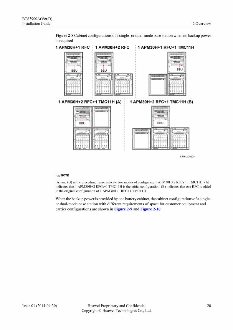
Figure 2-8 Cabinet configurations of a single- or dual-mode base station when no backup poweris required
NOTE
(A) and (B) in the preceding figure indicate two modes of configuring 1 APM30H+2 RFCs+1 TMC11H. (A)indicates that 1 APM30H+2 RFCs+1 TMC11H is the initial configuration. (B) indicates that one RFC is addedto the original configuration of 1 APM30H+1 RFC+1 TMC11H.
When the backup power is provided by one battery cabinet, the cabinet configurations of a single-or dual-mode base station with different requirements of space for customer equipment andcarrier configurations are shown in Figure 2-9 and Figure 2-10.
BTS3900A(Ver.D)Installation Guide 2 Overview
Issue 01 (2014-04-30) Huawei Proprietary and ConfidentialCopyright © Huawei Technologies Co., Ltd.
20

Figure 2-9 Cabinet configurations of a single- or dual-mode base station when backup poweris provided by an IBBS200D/IBBS200T
BTS3900A(Ver.D)Installation Guide 2 Overview
Issue 01 (2014-04-30) Huawei Proprietary and ConfidentialCopyright © Huawei Technologies Co., Ltd.
21
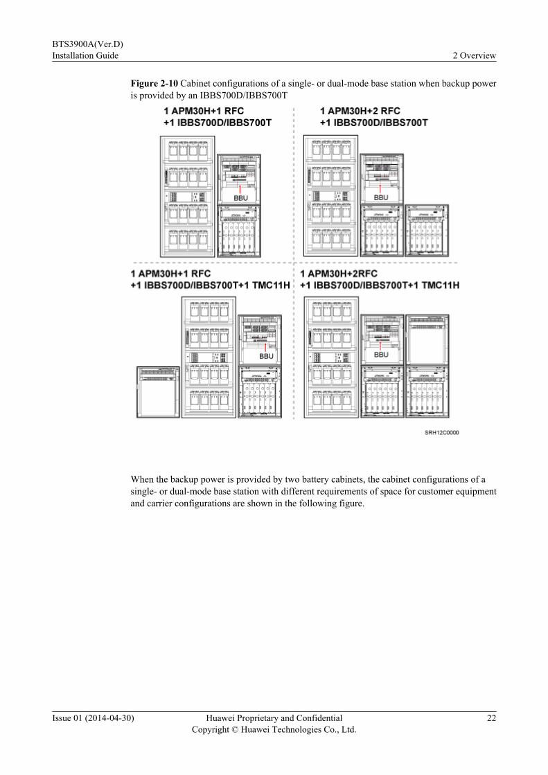
Figure 2-10 Cabinet configurations of a single- or dual-mode base station when backup poweris provided by an IBBS700D/IBBS700T
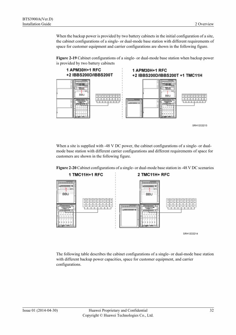
When the backup power is provided by two battery cabinets, the cabinet configurations of asingle- or dual-mode base station with different requirements of space for customer equipmentand carrier configurations are shown in the following figure.
BTS3900A(Ver.D)Installation Guide 2 Overview
Issue 01 (2014-04-30) Huawei Proprietary and ConfidentialCopyright © Huawei Technologies Co., Ltd.
22
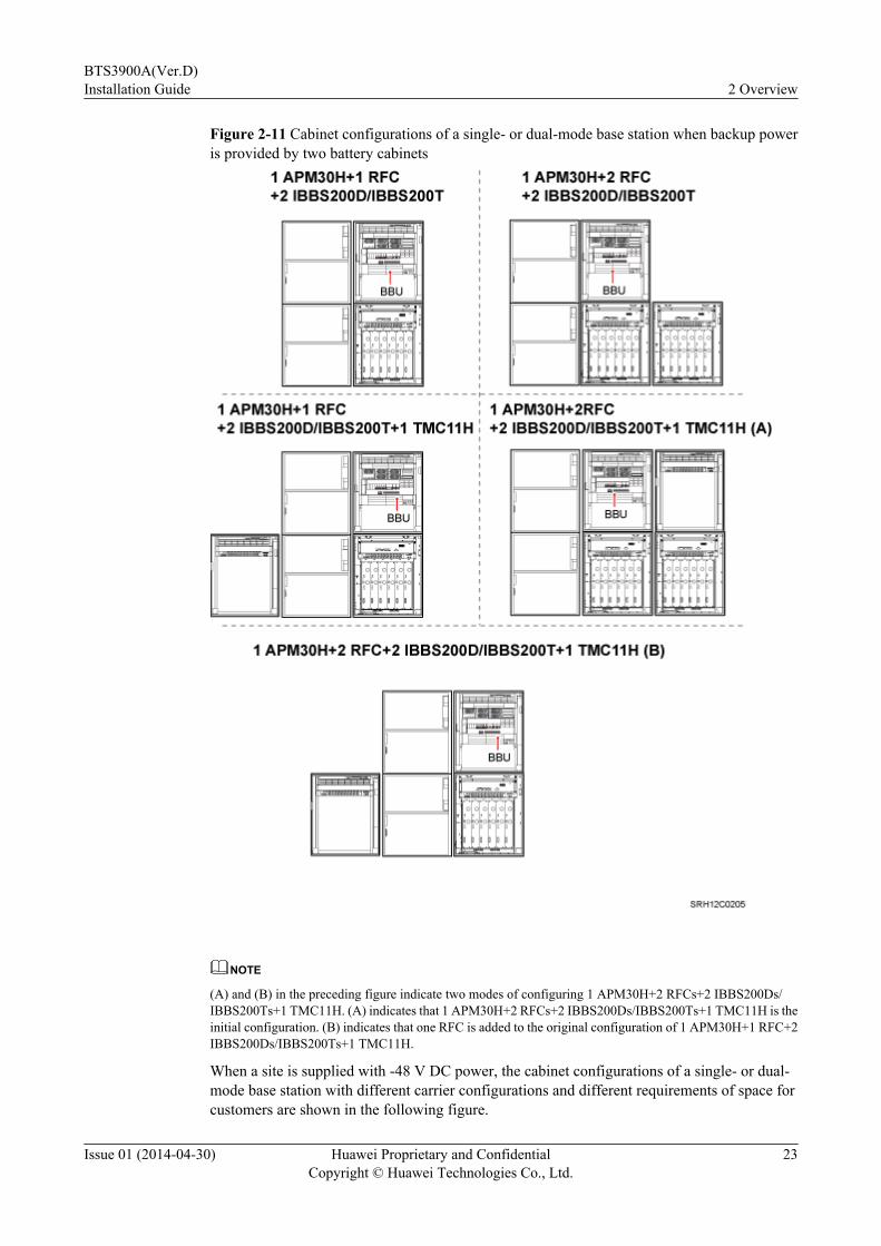
Figure 2-11 Cabinet configurations of a single- or dual-mode base station when backup poweris provided by two battery cabinets
NOTE
(A) and (B) in the preceding figure indicate two modes of configuring 1 APM30H+2 RFCs+2 IBBS200Ds/IBBS200Ts+1 TMC11H. (A) indicates that 1 APM30H+2 RFCs+2 IBBS200Ds/IBBS200Ts+1 TMC11H is theinitial configuration. (B) indicates that one RFC is added to the original configuration of 1 APM30H+1 RFC+2IBBS200Ds/IBBS200Ts+1 TMC11H.
When a site is supplied with -48 V DC power, the cabinet configurations of a single- or dual-mode base station with different carrier configurations and different requirements of space forcustomers are shown in the following figure.
BTS3900A(Ver.D)Installation Guide 2 Overview
Issue 01 (2014-04-30) Huawei Proprietary and ConfidentialCopyright © Huawei Technologies Co., Ltd.
23

Figure 2-12 Cabinet configurations of a single- or dual-mode base station in -48 V DC scenarios
NOTE
(A) and (B) in the preceding figure indicate two modes of configuring 2 TMC11Hs+2 RFCs. (A) indicatesthat 2 TMC11Hs+2 RFCs is the initial configuration. (B) indicates that one RFC is added to the initialconfiguration of 2 TMC11Hs + 1 RFC.
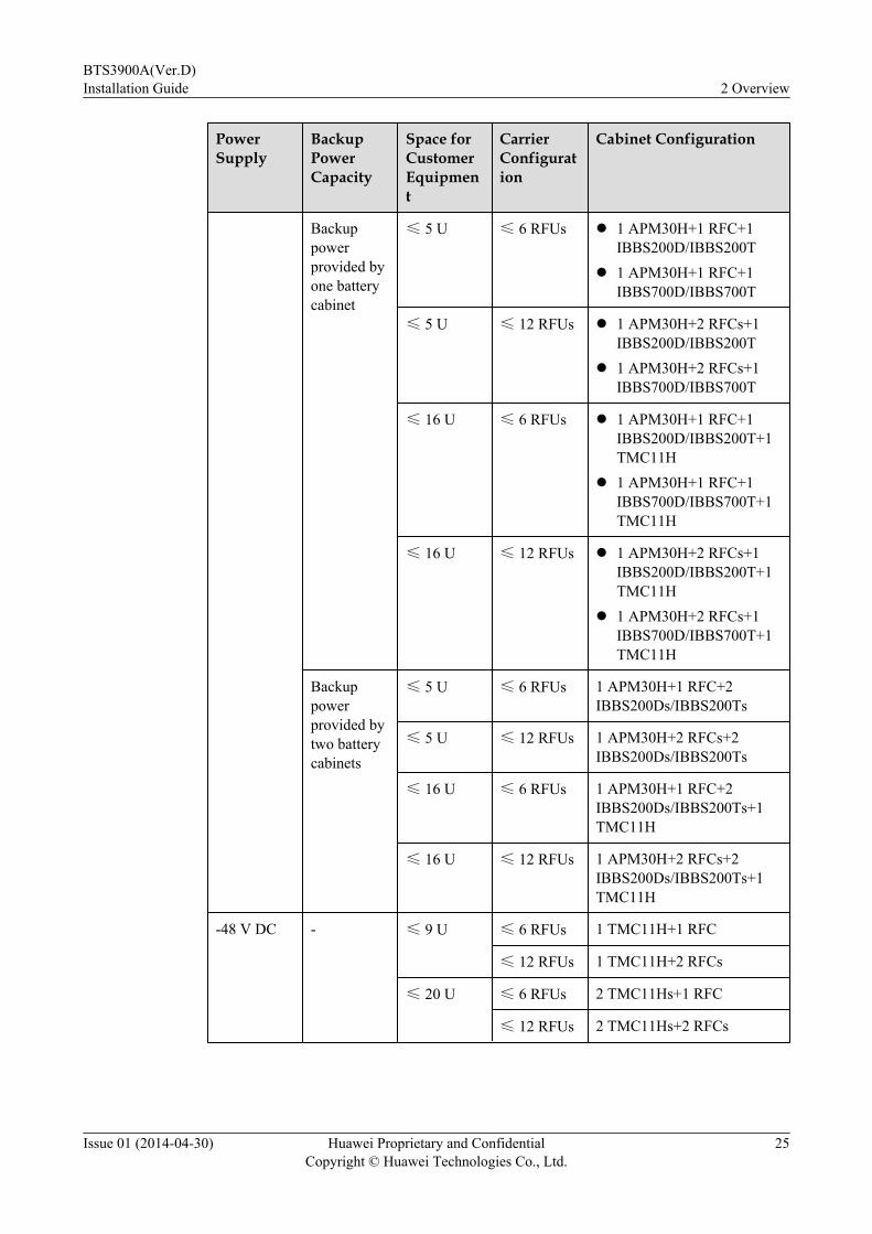
The following table describes the cabinet configurations of a single- or dual-mode base stationwith different backup power capacities, space for customer equipment, and carrierconfigurations.
Table 2-8 Cabinet configurations of a single- or dual-mode BTS3900A
PowerSupply
BackupPowerCapacity
Space forCustomerEquipment
CarrierConfiguration
Cabinet Configuration
110 V AC or220 V AC
No backuppower
≤ 5 U ≤ 6 RFUs 1 APM30H+1 RFC
≤ 5 U ≤ 12 RFUs 1 APM30H+2 RFCs
≤ 16 U ≤ 6 RFUs 1 APM30H+1 RFC+1TMC11H
≤ 16 U ≤ 12 RFUs 1 APM30H+2 RFCs+1TMC11H
BTS3900A(Ver.D)Installation Guide 2 Overview
Issue 01 (2014-04-30) Huawei Proprietary and ConfidentialCopyright © Huawei Technologies Co., Ltd.
24
PowerSupply
BackupPowerCapacity
Space forCustomerEquipment
CarrierConfiguration
Cabinet Configuration
Backuppowerprovided byone batterycabinet
≤ 5 U ≤ 6 RFUs l 1 APM30H+1 RFC+1IBBS200D/IBBS200T
l 1 APM30H+1 RFC+1IBBS700D/IBBS700T
≤ 5 U ≤ 12 RFUs l 1 APM30H+2 RFCs+1IBBS200D/IBBS200T
l 1 APM30H+2 RFCs+1IBBS700D/IBBS700T
≤ 16 U ≤ 6 RFUs l 1 APM30H+1 RFC+1IBBS200D/IBBS200T+1TMC11H
l 1 APM30H+1 RFC+1IBBS700D/IBBS700T+1TMC11H
≤ 16 U ≤ 12 RFUs l 1 APM30H+2 RFCs+1IBBS200D/IBBS200T+1TMC11H
l 1 APM30H+2 RFCs+1IBBS700D/IBBS700T+1TMC11H
Backuppowerprovided bytwo batterycabinets
≤ 5 U ≤ 6 RFUs 1 APM30H+1 RFC+2IBBS200Ds/IBBS200Ts
≤ 5 U ≤ 12 RFUs 1 APM30H+2 RFCs+2IBBS200Ds/IBBS200Ts
≤ 16 U ≤ 6 RFUs 1 APM30H+1 RFC+2IBBS200Ds/IBBS200Ts+1TMC11H
≤ 16 U ≤ 12 RFUs 1 APM30H+2 RFCs+2IBBS200Ds/IBBS200Ts+1TMC11H
-48 V DC - ≤ 9 U ≤ 6 RFUs 1 TMC11H+1 RFC
≤ 12 RFUs 1 TMC11H+2 RFCs
≤ 20 U ≤ 6 RFUs 2 TMC11Hs+1 RFC
≤ 12 RFUs 2 TMC11Hs+2 RFCs
BTS3900A(Ver.D)Installation Guide 2 Overview
Issue 01 (2014-04-30) Huawei Proprietary and ConfidentialCopyright © Huawei Technologies Co., Ltd.
25
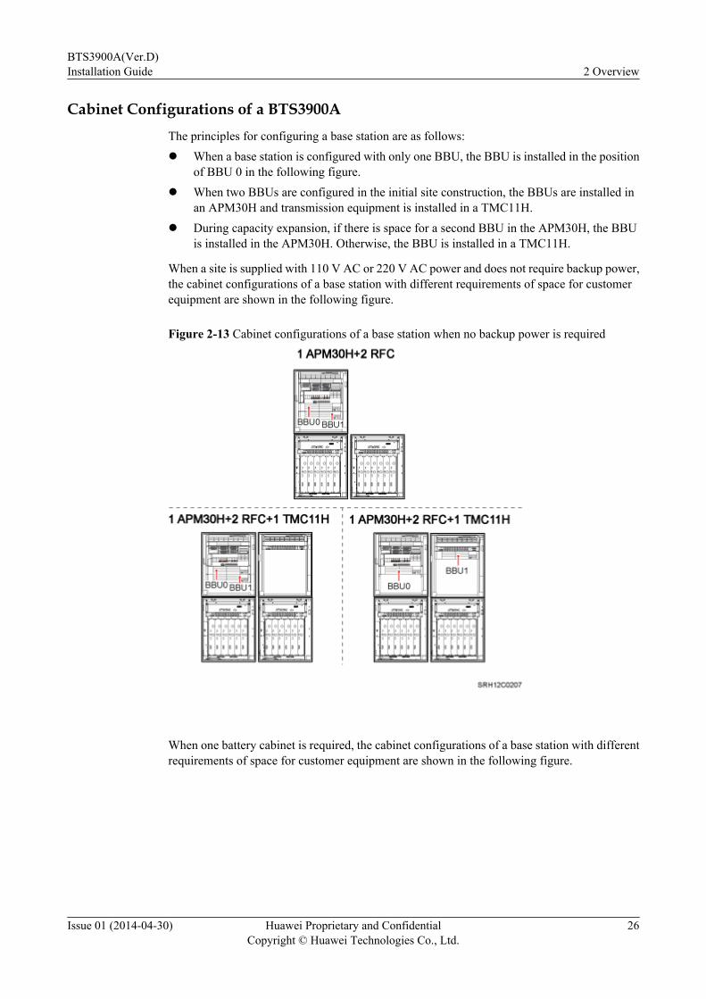
Cabinet Configurations of a BTS3900AThe principles for configuring a base station are as follows:l When a base station is configured with only one BBU, the BBU is installed in the position
of BBU 0 in the following figure.l When two BBUs are configured in the initial site construction, the BBUs are installed in
an APM30H and transmission equipment is installed in a TMC11H.l During capacity expansion, if there is space for a second BBU in the APM30H, the BBU
is installed in the APM30H. Otherwise, the BBU is installed in a TMC11H.
When a site is supplied with 110 V AC or 220 V AC power and does not require backup power,the cabinet configurations of a base station with different requirements of space for customerequipment are shown in the following figure.
Figure 2-13 Cabinet configurations of a base station when no backup power is required
When one battery cabinet is required, the cabinet configurations of a base station with differentrequirements of space for customer equipment are shown in the following figure.
BTS3900A(Ver.D)Installation Guide 2 Overview
Issue 01 (2014-04-30) Huawei Proprietary and ConfidentialCopyright © Huawei Technologies Co., Ltd.
26
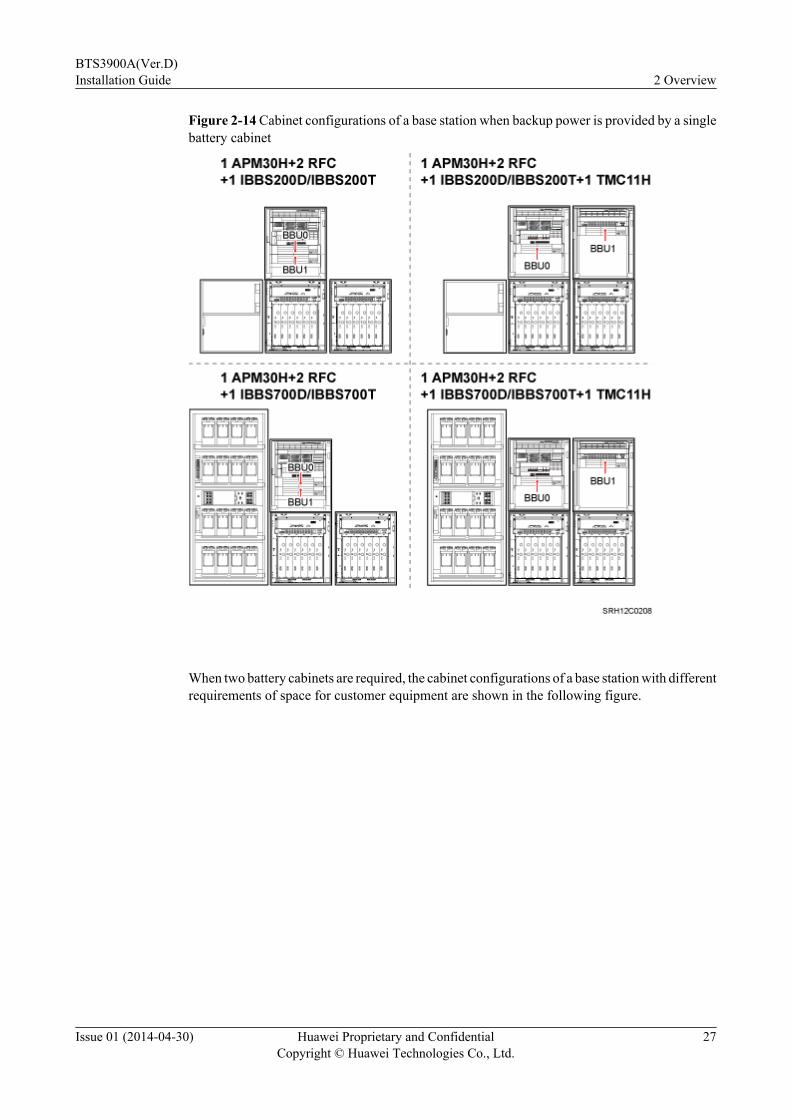
Figure 2-14 Cabinet configurations of a base station when backup power is provided by a singlebattery cabinet
When two battery cabinets are required, the cabinet configurations of a base station with differentrequirements of space for customer equipment are shown in the following figure.
BTS3900A(Ver.D)Installation Guide 2 Overview
Issue 01 (2014-04-30) Huawei Proprietary and ConfidentialCopyright © Huawei Technologies Co., Ltd.
27
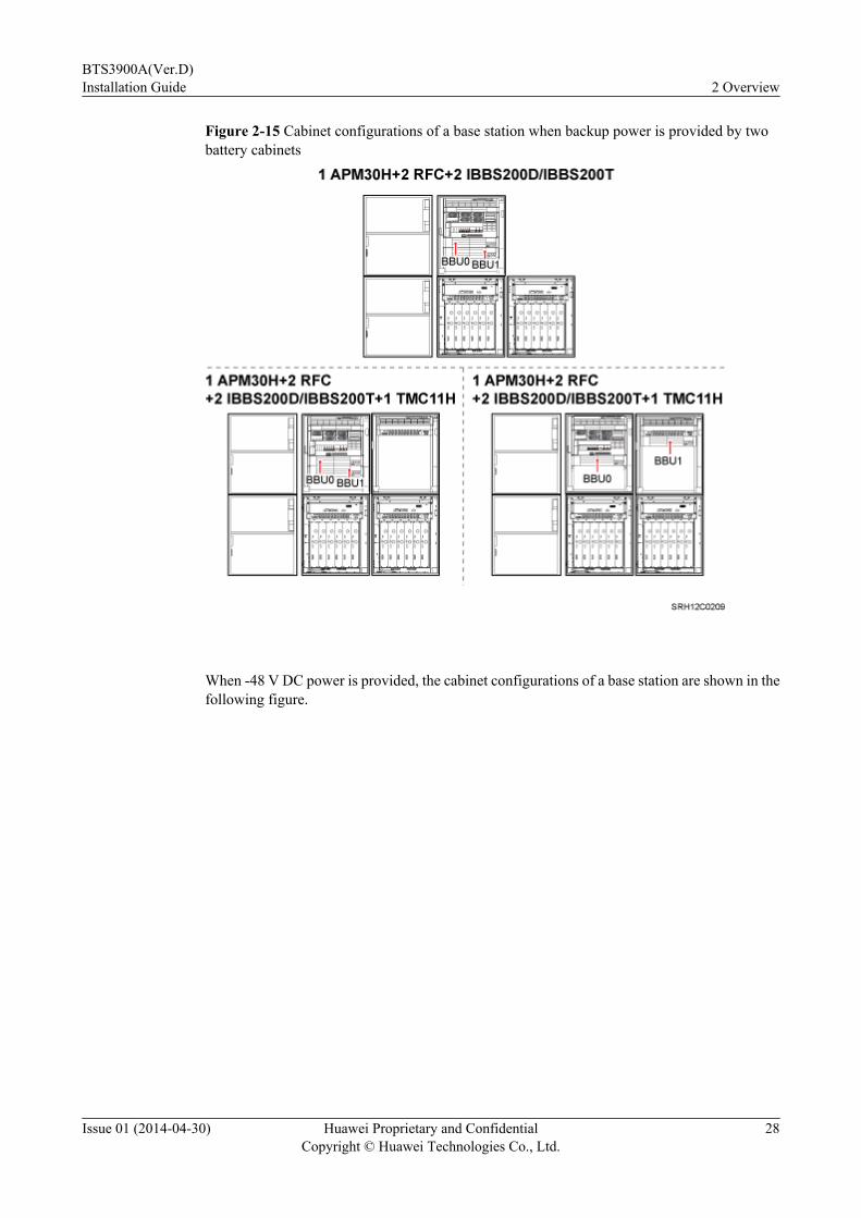
Figure 2-15 Cabinet configurations of a base station when backup power is provided by twobattery cabinets
When -48 V DC power is provided, the cabinet configurations of a base station are shown in thefollowing figure.
BTS3900A(Ver.D)Installation Guide 2 Overview
Issue 01 (2014-04-30) Huawei Proprietary and ConfidentialCopyright © Huawei Technologies Co., Ltd.
28
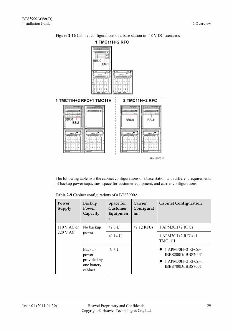
Figure 2-16 Cabinet configurations of a base station in -48 V DC scenarios
The following table lists the cabinet configurations of a base station with different requirementsof backup power capacities, space for customer equipment, and carrier configurations.
Table 2-9 Cabinet configurations of a BTS3900A
PowerSupply
BackupPowerCapacity
Space forCustomerEquipment
CarrierConfiguration
Cabinet Configuration
110 V AC or220 V AC
No backuppower
≤ 3 U ≤ 12 RFUs 1 APM30H+2 RFCs
≤ 14 U 1 APM30H+2 RFCs+1TMC11H
Backuppowerprovided byone batterycabinet
≤ 3 U l 1 APM30H+2 RFCs+1IBBS200D/IBBS200T
l 1 APM30H+2 RFCs+1IBBS700D/IBBS700T
BTS3900A(Ver.D)Installation Guide 2 Overview
Issue 01 (2014-04-30) Huawei Proprietary and ConfidentialCopyright © Huawei Technologies Co., Ltd.
29
PowerSupply
BackupPowerCapacity
Space forCustomerEquipment
CarrierConfiguration
Cabinet Configuration
≤ 14 U l 1 APM30H+2 RFCs+1IBBS200D/IBBS200T+1TMC11H
l 1 APM30H+2 RFCs+1IBBS700D/IBBS700T+1TMC11H
Backuppowerprovided bytwo batterycabinets
≤ 3 U 1 APM30H+2 RFCs+2IBBS200Ds/IBBS200Ts
≤ 14 U 1 APM30H+2 RFCs+2IBBS200Ds/IBBS200Ts+1TMC11H
-48 V DC - ≤ 7 U 1 TMC11H+2 RFCs
≤ 18 U 2 TMC11Hs+2 RFCs
2.3 BTS3900A (Ver.D) Configured with RFUs and RRUsWhen RFUs and RRUs are configured, a BTS3900A supports different cabinet configurationsin 110 V AC, 220 V AC, or -48 V DC power supply scenarios.
Cabinet Configuration Principlesl A single BTS3900A can be configured with a maximum of six RFUs and nine RRUs.
Therefore, deploy more than one site if the RFUs and RRUs to be configured exceed themaximum configuration.
l When a BTS3900A is configured with RFUs and RRUs, the maximum configuration ofRRUs is six RRUs of 2x60 W and three RRUs of 2x40 W.
Cabinet Configurations of a Single- or Dual-Mode BTS3900AA single- or dual-mode base station is configured with only one BBU, which is installed in theAPM30H or TMC11H.
When a site is supplied with 110 or 220 V AC power and does not require backup power, thecabinet configurations of a single- or dual-mode base station with different requirements of spacefor customer equipment and carrier configurations are shown in the following figure.
BTS3900A(Ver.D)Installation Guide 2 Overview
Issue 01 (2014-04-30) Huawei Proprietary and ConfidentialCopyright © Huawei Technologies Co., Ltd.
30
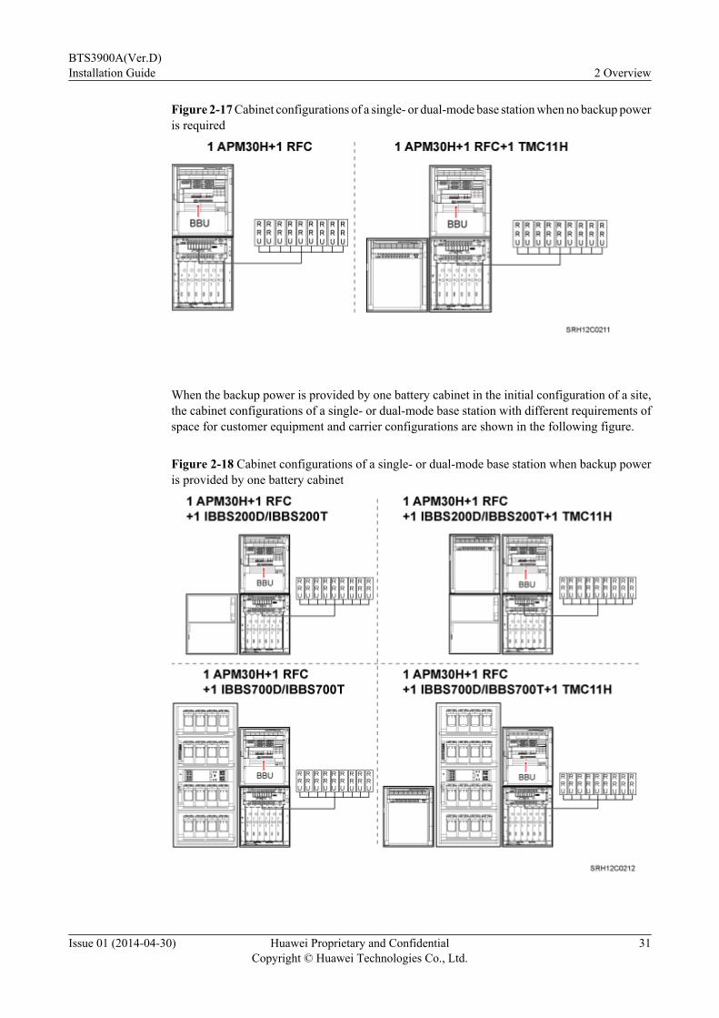
Figure 2-17 Cabinet configurations of a single- or dual-mode base station when no backup poweris required
When the backup power is provided by one battery cabinet in the initial configuration of a site,the cabinet configurations of a single- or dual-mode base station with different requirements ofspace for customer equipment and carrier configurations are shown in the following figure.
Figure 2-18 Cabinet configurations of a single- or dual-mode base station when backup poweris provided by one battery cabinet
BTS3900A(Ver.D)Installation Guide 2 Overview
Issue 01 (2014-04-30) Huawei Proprietary and ConfidentialCopyright © Huawei Technologies Co., Ltd.
31
When the backup power is provided by two battery cabinets in the initial configuration of a site,the cabinet configurations of a single- or dual-mode base station with different requirements ofspace for customer equipment and carrier configurations are shown in the following figure.
Figure 2-19 Cabinet configurations of a single- or dual-mode base station when backup poweris provided by two battery cabinets
When a site is supplied with -48 V DC power, the cabinet configurations of a single- or dual-mode base station with different carrier configurations and different requirements of space forcustomers are shown in the following figure.
Figure 2-20 Cabinet configurations of a single- or dual-mode base station in -48 V DC scenarios
The following table describes the cabinet configurations of a single- or dual-mode base stationwith different backup power capacities, space for customer equipment, and carrierconfigurations.
BTS3900A(Ver.D)Installation Guide 2 Overview
Issue 01 (2014-04-30) Huawei Proprietary and ConfidentialCopyright © Huawei Technologies Co., Ltd.
32

Table 2-10 Cabinet configurations of a single- or dual-mode BTS3900A
PowerSupply
BackupPowerCapacity
Space forCustomerEquipment
CarrierConfiguration
Cabinet Configuration
110 V AC or220 V AC
No backuppower
≤ 5 U ≤ 6 RFUs+9RRUs
1 APM30H+1 RFC
≤ 16 U 1 APM30H+1 RFC+1TMC11H
Backuppowerprovided byone batterycabinet inthe initialconfiguration
≤ 5 U l 1 APM30H+1 RFC+1IBBS200D/IBBS200T
l 1 APM30H+1 RFC+1IBBS700D/IBBS700T
≤ 16 U l 1 APM30H+1 RFC+1IBBS200D/IBBS200T+1TMC11H
l 1 APM30H+1 RFC+1IBBS700D/IBBS700T+1TMC11H
Backuppowerprovided bytwo batterycabinets inthe initialconfiguration
≤ 5 U 1 APM30H+1 RFC+2IBBS200Ds/IBBS200Ts
≤ 16 U 1 APM30H+1 RFC+2IBBS200Ds/IBBS200Ts+1TMC11H
-48 V DC - ≤ 9 U 1 TMC11H+1 RFC
≤ 20 U 2 TMC11Hs+1 RFC
Cabinet Configurations of a BTS3900A
The principles for configuring a base station are as follows:
l When a base station is configured with only one BBU, the BBU is installed in the positionof BBU 0 in the following figure.
l When two BBUs are configured in the initial site construction, the BBUs are installed inan APM30H and transmission equipment is installed in a TMC11H.
l During capacity expansion, if there is space for a second BBU in the APM30H, the BBUis installed in the APM30H. Otherwise, the BBU is installed in a TMC11H.
In the 110 V or 220 V AC power supply scenario, if power backup is not required, the cabinetconfigurations of a base station with different requirements of space for customer equipmentand carrier configurations are shown in the following figure.
BTS3900A(Ver.D)Installation Guide 2 Overview
Issue 01 (2014-04-30) Huawei Proprietary and ConfidentialCopyright © Huawei Technologies Co., Ltd.
33

Figure 2-21 Cabinet configurations of a base station when no backup power is required
When one battery cabinet is required, the cabinet configurations of a base station with differentrequirements of space for customer equipment and carrier configurations are shown in Figure2-22 and Figure 2-23.
BTS3900A(Ver.D)Installation Guide 2 Overview
Issue 01 (2014-04-30) Huawei Proprietary and ConfidentialCopyright © Huawei Technologies Co., Ltd.
34
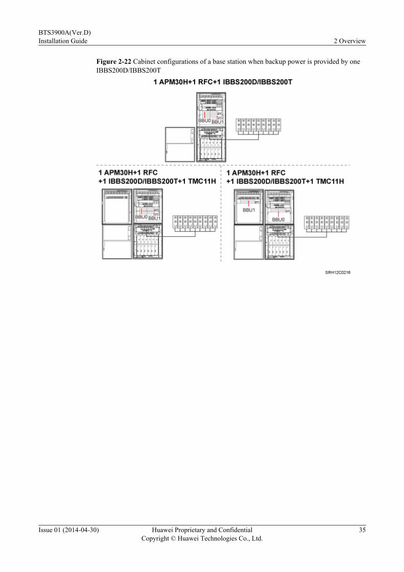
Figure 2-22 Cabinet configurations of a base station when backup power is provided by oneIBBS200D/IBBS200T
BTS3900A(Ver.D)Installation Guide 2 Overview
Issue 01 (2014-04-30) Huawei Proprietary and ConfidentialCopyright © Huawei Technologies Co., Ltd.
35
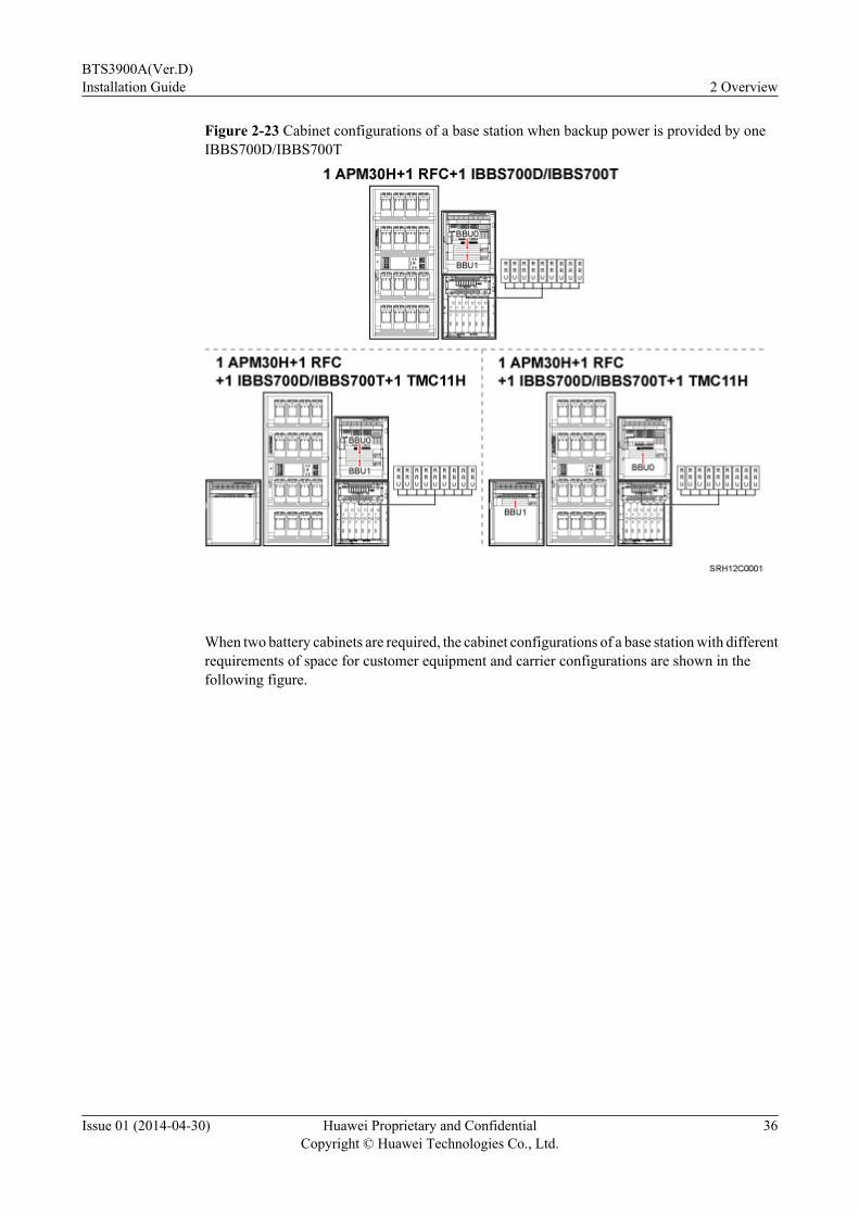
Figure 2-23 Cabinet configurations of a base station when backup power is provided by oneIBBS700D/IBBS700T
When two battery cabinets are required, the cabinet configurations of a base station with differentrequirements of space for customer equipment and carrier configurations are shown in thefollowing figure.
BTS3900A(Ver.D)Installation Guide 2 Overview
Issue 01 (2014-04-30) Huawei Proprietary and ConfidentialCopyright © Huawei Technologies Co., Ltd.
36
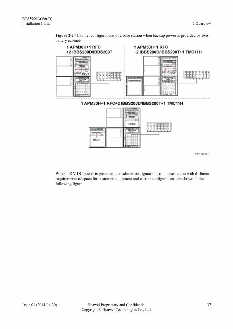
Figure 2-24 Cabinet configurations of a base station when backup power is provided by twobattery cabinets
When -48 V DC power is provided, the cabinet configurations of a base station with differentrequirements of space for customer equipment and carrier configurations are shown in thefollowing figure.
BTS3900A(Ver.D)Installation Guide 2 Overview
Issue 01 (2014-04-30) Huawei Proprietary and ConfidentialCopyright © Huawei Technologies Co., Ltd.
37

Figure 2-25 Cabinet configurations of a base station in -48 V DC scenarios
The following table lists the cabinet configurations of a base station with different requirementsof backup power capacities, space for customer equipment, and carrier configurations.
Table 2-11 Cabinet configurations of a BTS3900A
PowerSupply
BackupPowerCapacity
Space forCustomerEquipment
CarrierConfiguration
Cabinet Configuration
110 V AC or220 V AC
No backuppower
≤ 3 U ≤ 6 RFUs+9RRUs
1 APM30H+1 RFC
≤ 14 U 1 APM30H+1 RFC+1TMC11H
Backuppowerprovided byone batterycabinet
≤ 3 U l 1 APM30H+1 RFC+1IBBS200D/IBBS200T
l 1 APM30H+1 RFC+1IBBS700D/IBBS700T
BTS3900A(Ver.D)Installation Guide 2 Overview
Issue 01 (2014-04-30) Huawei Proprietary and ConfidentialCopyright © Huawei Technologies Co., Ltd.
38
PowerSupply
BackupPowerCapacity
Space forCustomerEquipment
CarrierConfiguration
Cabinet Configuration
≤ 14 U l 1 APM30H+1 RFC+1IBBS200D/IBBS200T+1TMC11H
l 1 APM30H+1 RFC+1IBBS700D/IBBS700T+1TMC11H
Backuppowerprovided bytwo batterycabinets
≤ 3 U 1 APM30H+1 RFC+2IBBS200Ds/IBBS200Ts
≤ 14 U 1 APM30H+1 RFC+2IBBS200Ds/IBBS200Ts+1TMC11H
-48 V DC - ≤ 7 U 1 TMC11H+1 RFC
≤ 18 U 2 TMC11Hs+1 RFC
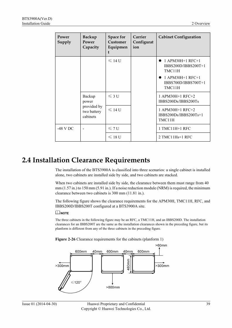
2.4 Installation Clearance RequirementsThe installation of the BTS3900A is classified into three scenarios: a single cabinet is installedalone, two cabinets are installed side by side, and two cabinets are stacked.
When two cabinets are installed side by side, the clearance between them must range from 40mm (1.57 in.) to 150 mm (5.91 in.). If a noise reduction module (NRM) is required, the minimumclearance between two cabinets is 300 mm (11.81 in.).
The following figure shows the clearance requirements for the APM30H, TMC11H, RFC, andIBBS200D/IBBS200T configured at a BTS3900A site.
NOTE
The three cabinets in the following figure may be an RFC, a TMC11H, and an IBBS200D. The installationclearances for an IBBS200T are the same as the installation clearances shown in the preceding figure, but itsplanform is different from any of the three cabinets in the preceding figure.
Figure 2-26 Clearance requirements for the cabinets (planform 1)
BTS3900A(Ver.D)Installation Guide 2 Overview
Issue 01 (2014-04-30) Huawei Proprietary and ConfidentialCopyright © Huawei Technologies Co., Ltd.
39
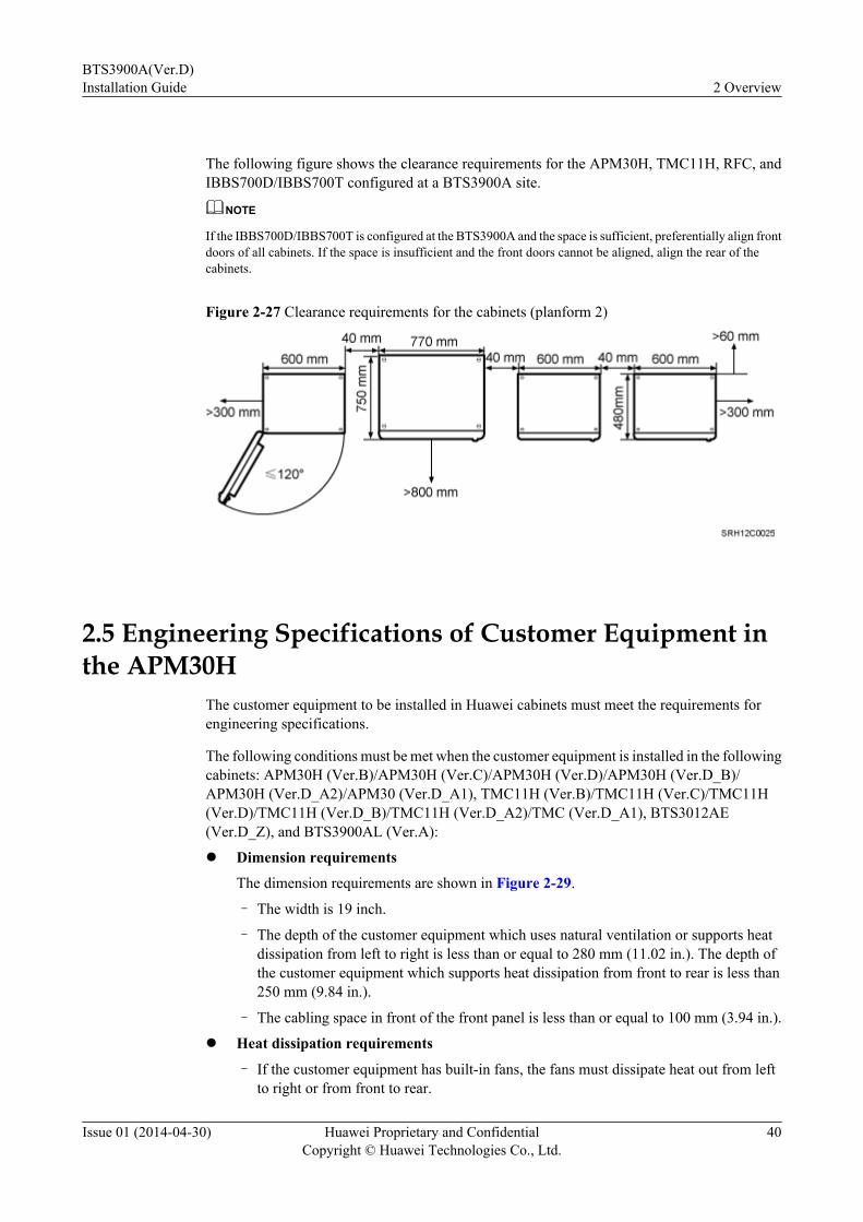
The following figure shows the clearance requirements for the APM30H, TMC11H, RFC, andIBBS700D/IBBS700T configured at a BTS3900A site.
NOTE
If the IBBS700D/IBBS700T is configured at the BTS3900A and the space is sufficient, preferentially align frontdoors of all cabinets. If the space is insufficient and the front doors cannot be aligned, align the rear of thecabinets.
Figure 2-27 Clearance requirements for the cabinets (planform 2)
2.5 Engineering Specifications of Customer Equipment inthe APM30H
The customer equipment to be installed in Huawei cabinets must meet the requirements forengineering specifications.
The following conditions must be met when the customer equipment is installed in the followingcabinets: APM30H (Ver.B)/APM30H (Ver.C)/APM30H (Ver.D)/APM30H (Ver.D_B)/APM30H (Ver.D_A2)/APM30 (Ver.D_A1), TMC11H (Ver.B)/TMC11H (Ver.C)/TMC11H(Ver.D)/TMC11H (Ver.D_B)/TMC11H (Ver.D_A2)/TMC (Ver.D_A1), BTS3012AE(Ver.D_Z), and BTS3900AL (Ver.A):
l Dimension requirements
The dimension requirements are shown in Figure 2-29.
– The width is 19 inch.
– The depth of the customer equipment which uses natural ventilation or supports heatdissipation from left to right is less than or equal to 280 mm (11.02 in.). The depth ofthe customer equipment which supports heat dissipation from front to rear is less than250 mm (9.84 in.).
– The cabling space in front of the front panel is less than or equal to 100 mm (3.94 in.).
l Heat dissipation requirements
– If the customer equipment has built-in fans, the fans must dissipate heat out from leftto right or from front to rear.
BTS3900A(Ver.D)Installation Guide 2 Overview
Issue 01 (2014-04-30) Huawei Proprietary and ConfidentialCopyright © Huawei Technologies Co., Ltd.
40
– If the customer equipment does not have built-in fans but uses natural ventilation, aminimum of 1 U space must be reserved above and below the customer equipment toensure heat dissipation.
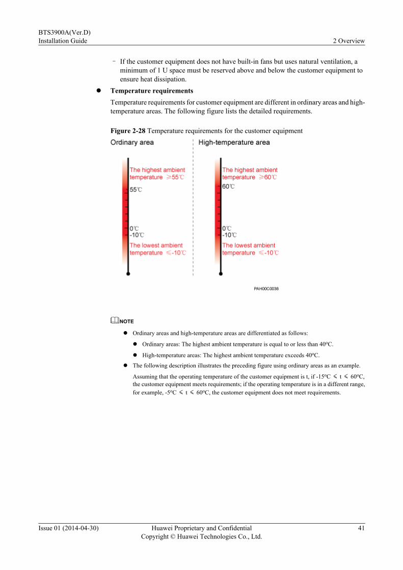
l Temperature requirementsTemperature requirements for customer equipment are different in ordinary areas and high-temperature areas. The following figure lists the detailed requirements.
Figure 2-28 Temperature requirements for the customer equipment
NOTE
l Ordinary areas and high-temperature areas are differentiated as follows:
l Ordinary areas: The highest ambient temperature is equal to or less than 40oC.
l High-temperature areas: The highest ambient temperature exceeds 40oC.
l The following description illustrates the preceding figure using ordinary areas as an example.
Assuming that the operating temperature of the customer equipment is t, if -15oC ≤ t ≤ 60oC,the customer equipment meets requirements; if the operating temperature is in a different range,for example, -5oC ≤ t ≤ 60oC, the customer equipment does not meet requirements.
BTS3900A(Ver.D)Installation Guide 2 Overview
Issue 01 (2014-04-30) Huawei Proprietary and ConfidentialCopyright © Huawei Technologies Co., Ltd.
41
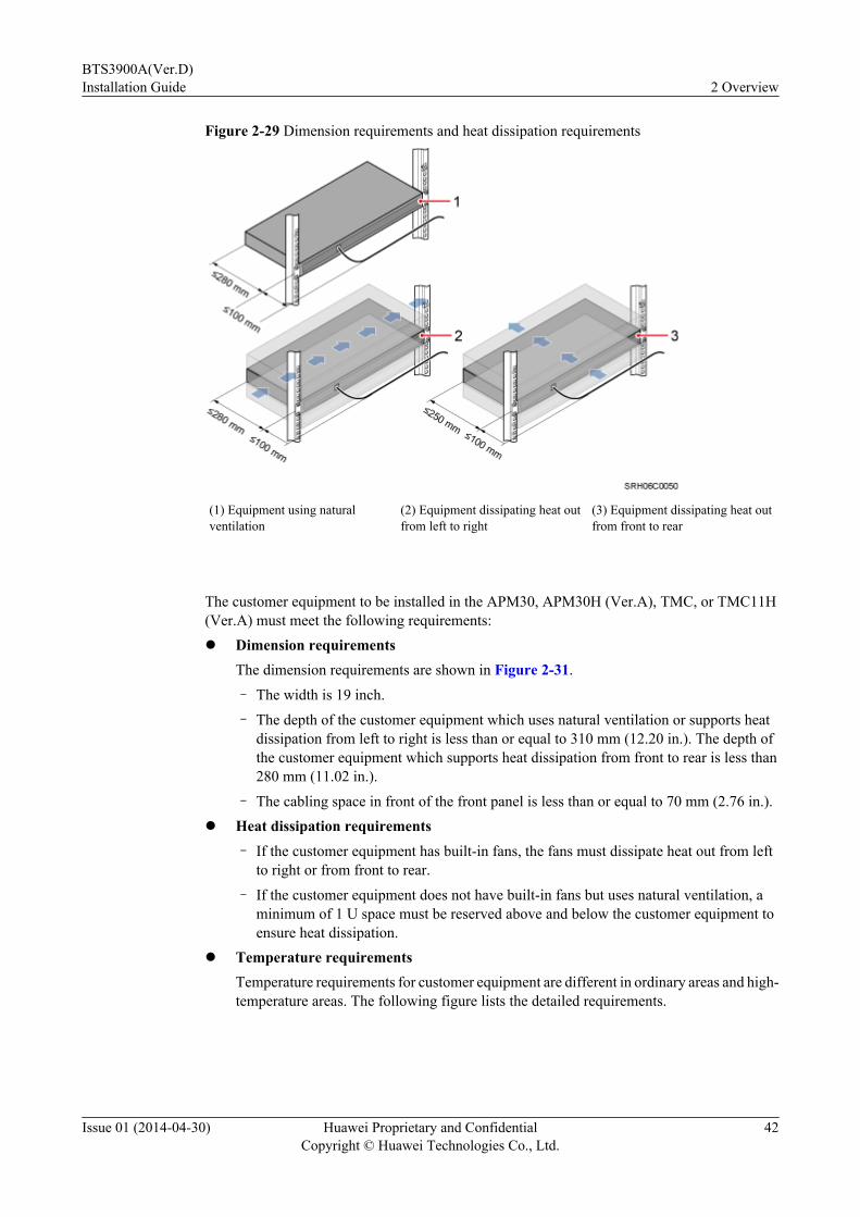
Figure 2-29 Dimension requirements and heat dissipation requirements
(1) Equipment using naturalventilation
(2) Equipment dissipating heat outfrom left to right
(3) Equipment dissipating heat outfrom front to rear
The customer equipment to be installed in the APM30, APM30H (Ver.A), TMC, or TMC11H(Ver.A) must meet the following requirements:l Dimension requirements
The dimension requirements are shown in Figure 2-31.
– The width is 19 inch.
– The depth of the customer equipment which uses natural ventilation or supports heatdissipation from left to right is less than or equal to 310 mm (12.20 in.). The depth ofthe customer equipment which supports heat dissipation from front to rear is less than280 mm (11.02 in.).
– The cabling space in front of the front panel is less than or equal to 70 mm (2.76 in.).l Heat dissipation requirements
– If the customer equipment has built-in fans, the fans must dissipate heat out from leftto right or from front to rear.
– If the customer equipment does not have built-in fans but uses natural ventilation, aminimum of 1 U space must be reserved above and below the customer equipment toensure heat dissipation.
l Temperature requirementsTemperature requirements for customer equipment are different in ordinary areas and high-temperature areas. The following figure lists the detailed requirements.
BTS3900A(Ver.D)Installation Guide 2 Overview
Issue 01 (2014-04-30) Huawei Proprietary and ConfidentialCopyright © Huawei Technologies Co., Ltd.
42

Figure 2-30 Temperature requirements for the customer equipment
NOTE
l Ordinary areas and high-temperature areas are differentiated as follows:
l Ordinary areas: The highest ambient temperature is equal to or less than 40oC.
l High-temperature areas: The highest ambient temperature exceeds 40oC.
l The following description illustrates the preceding figure using ordinary areas as an example.
Assuming that the operating temperature of the customer equipment is t, if -15oC ≤ t ≤ 60oC,the customer equipment meets requirements; if the operating temperature is in a different range,for example, -5oC ≤ t ≤ 60oC, the customer equipment does not meet requirements.
BTS3900A(Ver.D)Installation Guide 2 Overview
Issue 01 (2014-04-30) Huawei Proprietary and ConfidentialCopyright © Huawei Technologies Co., Ltd.
43

Figure 2-31 Dimension requirements and heat dissipation requirements
(1) Equipment using naturalventilation
(2) Equipment dissipating heat outfrom left to right
(3) Equipment dissipating heat outfrom front to rear
BTS3900A(Ver.D)Installation Guide 2 Overview
Issue 01 (2014-04-30) Huawei Proprietary and ConfidentialCopyright © Huawei Technologies Co., Ltd.
44
3 Installation Preparations
About This Chapter
This chapter lists the tools and instruments that must be obtained before the installation. It alsospecifies the skills that the onsite personnel must have.
3.1 Document PreparationsThis section lists the documents that must be obtained before the installation.
3.2 Tools and InstrumentsThis section lists the tools and instruments that must be obtained before installation.
3.3 Requirements for Onsite PersonnelOnsite personnel must be qualified and trained. Before performing any operation, onsitepersonnel must be familiar with correct operation methods and safety precautions.
BTS3900A(Ver.D)Installation Guide 3 Installation Preparations
Issue 01 (2014-04-30) Huawei Proprietary and ConfidentialCopyright © Huawei Technologies Co., Ltd.
45
3.1 Document PreparationsThis section lists the documents that must be obtained before the installation.
l Before the installation, familiarize yourself with related information in the followingdocuments:
– Hardware descriptions of base stations to be installed: BTS3900A (Ver.B) HardwareDescription, BTS3900A (Ver.C) Hardware Description, and BTS3900A (Ver.D)Hardware Description
– Hardware descriptions of cabinets configured for each base station:APM30H&TMC11H&IBBS200D&IBBS200T (Ver.B) Product Description,APM30H&TMC11H&IBBS200D&IBBS200T (Ver.C) Product Description, andAPM30H&TMC11H&IBBS200D&IBBS200T (Ver.D) Product Description.
– Safety Precautionsl During the installation, refer to the following document:
– Installation Reference
3.2 Tools and InstrumentsThis section lists the tools and instruments that must be obtained before installation.
Marker Phillips screwdriver (M3 toM6)
Flat-head screwdriver (M3 toM6)
Diagonal pliers
32 mm (1.26 in.)combination wrench
Socket wrench Torque wrench
Power cable crimping tool RJ45 crimping tool Cable cutter
Rubber mallet Soldering iron Wire stripper
BTS3900A(Ver.D)Installation Guide 3 Installation Preparations
Issue 01 (2014-04-30) Huawei Proprietary and ConfidentialCopyright © Huawei Technologies Co., Ltd.
46
Hammer drill (Φ16) Heat gun Level
Multimeter Measuring tape Vacuum cleaner
ESD wrist strap ESD gloves Torque screwdriver
Gloves Utility knife Hydraulic pliers
Torx screwdriver - -
3.3 Requirements for Onsite PersonnelOnsite personnel must be qualified and trained. Before performing any operation, onsitepersonnel must be familiar with correct operation methods and safety precautions.
Before the installation, pay attention to the following:
l The customer's technical engineers must be trained by Huawei and be familiar with theproper installation and operation methods.
l The number of onsite personnel depends on the engineering schedule and installationenvironment. Generally, three to five onsite personnel are necessary.
BTS3900A(Ver.D)Installation Guide 3 Installation Preparations
Issue 01 (2014-04-30) Huawei Proprietary and ConfidentialCopyright © Huawei Technologies Co., Ltd.
47

4 Unpacking Check
Unpack and check the delivered equipment to ensure that all the materials are included and intact.
Context
CAUTIONThe gravity center of some cabinets is in the front, for example, the BTS3900AL and IBBS700T.Therefore, avoid toppling of the cabinet when the door of the cabinet is opened, especially whenyou unpack the cabinet or before it has been secured onto a base.
NOTICEl Power on a cabinet or BBU within seven days after unpacking it.l Power on an RRU within 24 hours after unpacking it.
NOTE
When transporting, moving, or installing the equipment, components, or parts, you must:
l Prevent them from colliding with doors, walls, shelves, or other objects.
l Wear clean gloves, and avoid touching the equipment, components, or parts with bare hands, sweat-soaked gloves, or dirty gloves.
Procedure
Step 1 Check the total number of articles in each case according to the packing list.
BTS3900A(Ver.D)Installation Guide 4 Unpacking Check
Issue 01 (2014-04-30) Huawei Proprietary and ConfidentialCopyright © Huawei Technologies Co., Ltd.
48
If... Then...
The total number tallies with the packinglist
Go to Step 2.
The total number does not tally with thepacking list
Find out the cause and report any missingarticles to the local Huawei office.
Step 2 Check the exterior of the packing case.
If... Then...
The outer packing case is intact Go to Step 3.
The outer packing is severely damaged orsoaked
Find out the cause and report the situation tothe local Huawei office.
Step 3 Check the type and quantity of the equipment in the cases according to the packing list.
If... Then...
Types and quantity of the articles tally withthose on the packing list
Sign the Packing List with the customer.
There are any goods missing, incorrectlydelivered, or damaged
Report the situation to the local Huawei office.
CAUTIONTo protect the equipment and prevent damage to the equipment, you are advised to keep theunpacked equipment and packing materials indoors, take photos of the stocking environment,packing case or carton, packing materials, and any rusted or eroded equipment, and then file thephotos.
----End
BTS3900A(Ver.D)Installation Guide 4 Unpacking Check
Issue 01 (2014-04-30) Huawei Proprietary and ConfidentialCopyright © Huawei Technologies Co., Ltd.
49

5 Obtaining the ESN
The electronic serial number (ESN) is a unique identifier of a NE. Record the ESN of the basestation before the installation for future commissioning.
Procedure
Step 1 Record the ESN on the BBU.l If there is no label on the FAN unit of the BBU, the ESN is printed on a mounting ear of the
BBU, as shown in Figure 5-1. Record the ESN and base station information.l If there is a label on the FAN unit of the BBU, the ESN is printed on the label and a mounting
ear of the BBU, as shown in Figure 5-2. Remove the label and record the base stationinformation on the label printed with Site.
NOTE
The base station information includes the name, ID, and location of the base station.
Figure 5-1 ESN position (1)
BTS3900A(Ver.D)Installation Guide 5 Obtaining the ESN
Issue 01 (2014-04-30) Huawei Proprietary and ConfidentialCopyright © Huawei Technologies Co., Ltd.
50
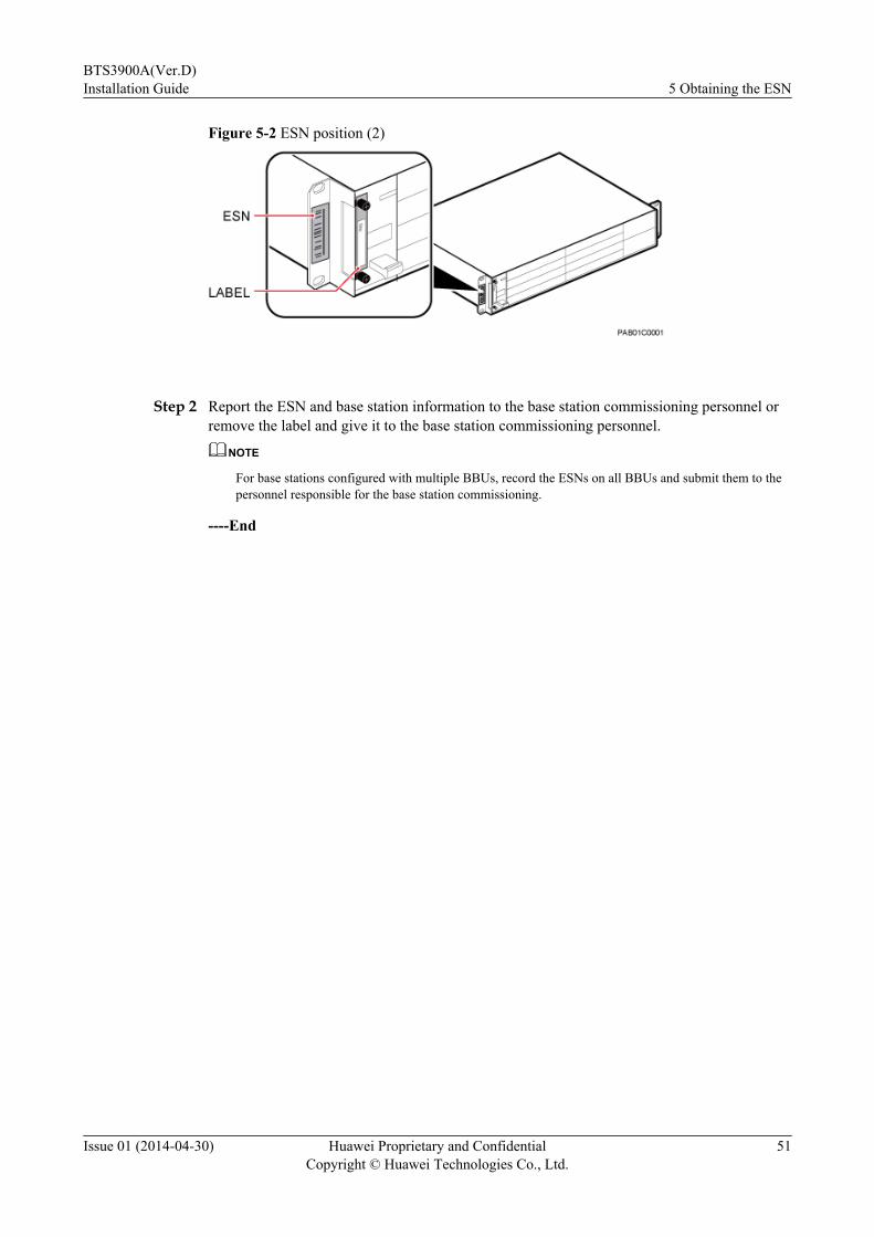
Figure 5-2 ESN position (2)
Step 2 Report the ESN and base station information to the base station commissioning personnel orremove the label and give it to the base station commissioning personnel.
NOTE
For base stations configured with multiple BBUs, record the ESNs on all BBUs and submit them to thepersonnel responsible for the base station commissioning.
----End
BTS3900A(Ver.D)Installation Guide 5 Obtaining the ESN
Issue 01 (2014-04-30) Huawei Proprietary and ConfidentialCopyright © Huawei Technologies Co., Ltd.
51
6 Installation Process
The process of installing the BTS3900A consists of the following procedures: installing thebases, installing the cabinets, installing optional modules, installing cables, installation check,power-on check, and subsequent operations.
The following figure shows the installation process.
BTS3900A(Ver.D)Installation Guide 6 Installation Process
Issue 01 (2014-04-30) Huawei Proprietary and ConfidentialCopyright © Huawei Technologies Co., Ltd.
52

Figure 6-1 Installation process
BTS3900A(Ver.D)Installation Guide 6 Installation Process
Issue 01 (2014-04-30) Huawei Proprietary and ConfidentialCopyright © Huawei Technologies Co., Ltd.
53

7 Checking the Installed Modules and Cables
About This Chapter
After installing modules and cables in the cabinet, you need to check that the modules and cablesare installed securely.
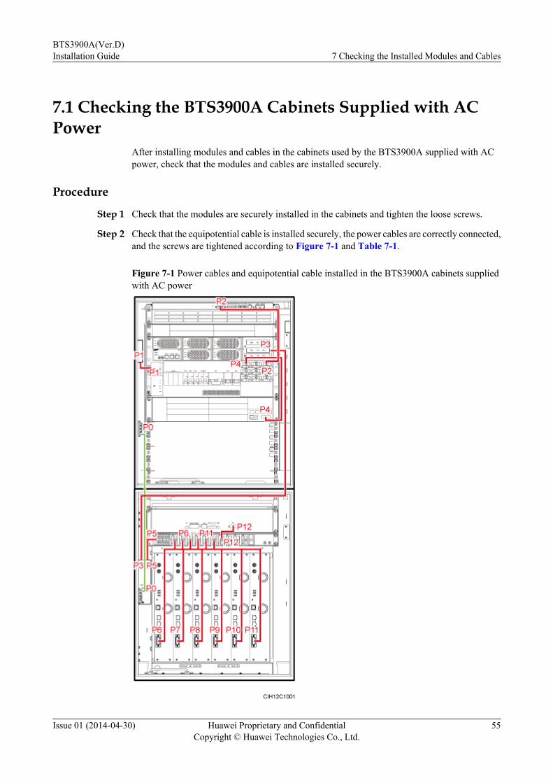
7.1 Checking the BTS3900A Cabinets Supplied with AC PowerAfter installing modules and cables in the cabinets used by the BTS3900A supplied with ACpower, check that the modules and cables are installed securely.
7.2 Checking the BTS3900A Cabinets Supplied with -48 V DC PowerModules and cables have been installed in the BTS3900A cabinets supplied with -48 V DCpower before delivery. You need to check whether the modules and cables are installed securely.
BTS3900A(Ver.D)Installation Guide 7 Checking the Installed Modules and Cables
Issue 01 (2014-04-30) Huawei Proprietary and ConfidentialCopyright © Huawei Technologies Co., Ltd.
54
7.1 Checking the BTS3900A Cabinets Supplied with ACPower
After installing modules and cables in the cabinets used by the BTS3900A supplied with ACpower, check that the modules and cables are installed securely.
Procedure
Step 1 Check that the modules are securely installed in the cabinets and tighten the loose screws.
Step 2 Check that the equipotential cable is installed securely, the power cables are correctly connected,and the screws are tightened according to Figure 7-1 and Table 7-1.
Figure 7-1 Power cables and equipotential cable installed in the BTS3900A cabinets suppliedwith AC power
BTS3900A(Ver.D)Installation Guide 7 Checking the Installed Modules and Cables
Issue 01 (2014-04-30) Huawei Proprietary and ConfidentialCopyright © Huawei Technologies Co., Ltd.
55
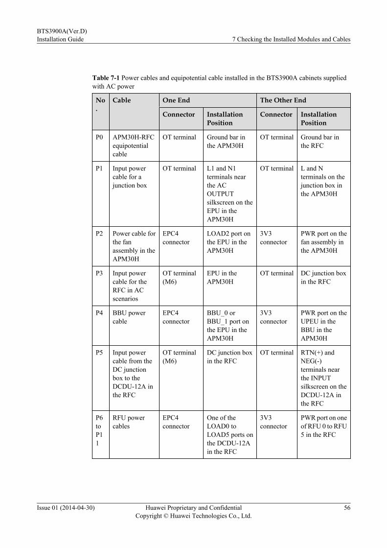
Table 7-1 Power cables and equipotential cable installed in the BTS3900A cabinets suppliedwith AC power
No.
Cable One End The Other End
Connector InstallationPosition
Connector InstallationPosition
P0 APM30H-RFCequipotentialcable
OT terminal Ground bar inthe APM30H
OT terminal Ground bar inthe RFC
P1 Input powercable for ajunction box
OT terminal L1 and N1terminals nearthe ACOUTPUTsilkscreen on theEPU in theAPM30H
OT terminal L and Nterminals on thejunction box inthe APM30H
P2 Power cable forthe fanassembly in theAPM30H
EPC4connector
LOAD2 port onthe EPU in theAPM30H
3V3connector
PWR port on thefan assembly inthe APM30H
P3 Input powercable for theRFC in ACscenarios
OT terminal(M6)
EPU in theAPM30H
OT terminal DC junction boxin the RFC
P4 BBU powercable
EPC4connector
BBU_0 orBBU_1 port onthe EPU in theAPM30H
3V3connector
PWR port on theUPEU in theBBU in theAPM30H
P5 Input powercable from theDC junctionbox to theDCDU-12A inthe RFC
OT terminal(M6)
DC junction boxin the RFC
OT terminal RTN(+) andNEG(-)terminals nearthe INPUTsilkscreen on theDCDU-12A inthe RFC
P6toP11
RFU powercables
EPC4connector
One of theLOAD0 toLOAD5 ports onthe DCDU-12Ain the RFC
3V3connector
PWR port on oneof RFU 0 to RFU5 in the RFC
BTS3900A(Ver.D)Installation Guide 7 Checking the Installed Modules and Cables
Issue 01 (2014-04-30) Huawei Proprietary and ConfidentialCopyright © Huawei Technologies Co., Ltd.
56

No.
Cable One End The Other End
Connector InstallationPosition
Connector InstallationPosition
P12
Power cable forthe fanassembly in theRFC
EPC4connector
LOAD6 port onthe DCDU-12Ain the RFC
3V3connector
PWR port on thefan assembly inthe RFC
Step 3 Check that signal cables are connected securely and correctly in the cabinets according to Figure7-2 and Table 7-2.
Figure 7-2 Signal cables installed in the BTS3900A cabinets supplied with AC power
BTS3900A(Ver.D)Installation Guide 7 Checking the Installed Modules and Cables
Issue 01 (2014-04-30) Huawei Proprietary and ConfidentialCopyright © Huawei Technologies Co., Ltd.
57
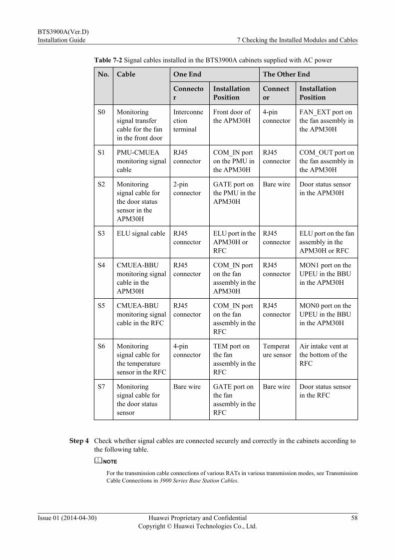
Table 7-2 Signal cables installed in the BTS3900A cabinets supplied with AC power
No. Cable One End The Other End
Connector
InstallationPosition
Connector
InstallationPosition
S0 Monitoringsignal transfercable for the fanin the front door
Interconnectionterminal
Front door ofthe APM30H
4-pinconnector
FAN_EXT port onthe fan assembly inthe APM30H
S1 PMU-CMUEAmonitoring signalcable
RJ45connector
COM_IN porton the PMU inthe APM30H
RJ45connector
COM_OUT port onthe fan assembly inthe APM30H
S2 Monitoringsignal cable forthe door statussensor in theAPM30H
2-pinconnector
GATE port onthe PMU in theAPM30H
Bare wire Door status sensorin the APM30H
S3 ELU signal cable RJ45connector
ELU port in theAPM30H orRFC
RJ45connector
ELU port on the fanassembly in theAPM30H or RFC
S4 CMUEA-BBUmonitoring signalcable in theAPM30H
RJ45connector
COM_IN porton the fanassembly in theAPM30H
RJ45connector
MON1 port on theUPEU in the BBUin the APM30H
S5 CMUEA-BBUmonitoring signalcable in the RFC
RJ45connector
COM_IN porton the fanassembly in theRFC
RJ45connector
MON0 port on theUPEU in the BBUin the APM30H
S6 Monitoringsignal cable forthe temperaturesensor in the RFC
4-pinconnector
TEM port onthe fanassembly in theRFC
Temperature sensor
Air intake vent atthe bottom of theRFC
S7 Monitoringsignal cable forthe door statussensor
Bare wire GATE port onthe fanassembly in theRFC
Bare wire Door status sensorin the RFC
Step 4 Check whether signal cables are connected securely and correctly in the cabinets according tothe following table.
NOTE
For the transmission cable connections of various RATs in various transmission modes, see TransmissionCable Connections in 3900 Series Base Station Cables.
BTS3900A(Ver.D)Installation Guide 7 Checking the Installed Modules and Cables
Issue 01 (2014-04-30) Huawei Proprietary and ConfidentialCopyright © Huawei Technologies Co., Ltd.
58
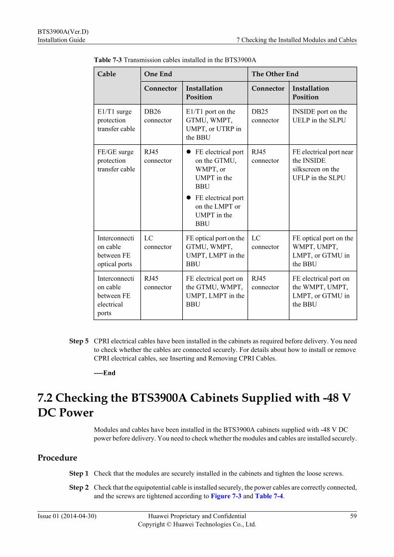
Table 7-3 Transmission cables installed in the BTS3900A
Cable One End The Other End
Connector InstallationPosition
Connector InstallationPosition
E1/T1 surgeprotectiontransfer cable
DB26connector
E1/T1 port on theGTMU, WMPT,UMPT, or UTRP inthe BBU
DB25connector
INSIDE port on theUELP in the SLPU
FE/GE surgeprotectiontransfer cable
RJ45connector
l FE electrical porton the GTMU,WMPT, orUMPT in theBBU
l FE electrical porton the LMPT orUMPT in theBBU
RJ45connector
FE electrical port nearthe INSIDEsilkscreen on theUFLP in the SLPU
Interconnection cablebetween FEoptical ports
LCconnector
FE optical port on theGTMU, WMPT,UMPT, LMPT in theBBU
LCconnector
FE optical port on theWMPT, UMPT,LMPT, or GTMU inthe BBU
Interconnection cablebetween FEelectricalports
RJ45connector
FE electrical port onthe GTMU, WMPT,UMPT, LMPT in theBBU
RJ45connector
FE electrical port onthe WMPT, UMPT,LMPT, or GTMU inthe BBU
Step 5 CPRI electrical cables have been installed in the cabinets as required before delivery. You needto check whether the cables are connected securely. For details about how to install or removeCPRI electrical cables, see Inserting and Removing CPRI Cables.
----End
7.2 Checking the BTS3900A Cabinets Supplied with -48 VDC Power
Modules and cables have been installed in the BTS3900A cabinets supplied with -48 V DCpower before delivery. You need to check whether the modules and cables are installed securely.
Procedure
Step 1 Check that the modules are securely installed in the cabinets and tighten the loose screws.
Step 2 Check that the equipotential cable is installed securely, the power cables are correctly connected,and the screws are tightened according to Figure 7-3 and Table 7-4.
BTS3900A(Ver.D)Installation Guide 7 Checking the Installed Modules and Cables
Issue 01 (2014-04-30) Huawei Proprietary and ConfidentialCopyright © Huawei Technologies Co., Ltd.
59

Figure 7-3 Power cables and equipotential cable installed in BTS3900A cabinets supplied with-48 V DC power
Table 7-4 Power cables and equipotential cable installed in BTS3900A cabinets supplied with-48 V DC power
No. Cable One End The Other End
Connector
InstallationPosition
Connector InstallationPosition
P0 TMC11H-RFCequipotentialcable
OTterminal
Ground bar inthe TMC11H
OT terminal Ground bar inthe RFC
BTS3900A(Ver.D)Installation Guide 7 Checking the Installed Modules and Cables
Issue 01 (2014-04-30) Huawei Proprietary and ConfidentialCopyright © Huawei Technologies Co., Ltd.
60

No. Cable One End The Other End
Connector
InstallationPosition
Connector InstallationPosition
P1 Input powercables for theTMC11H
OTterminal
Junction box inthe RFC
OT terminal RTN(+) andNEG(-)terminals in theINPUT part ofthe DCDU-12Cin the TMC11H
P2 Power cablefor the fan inthe TMC11H
EPC4connector
LOAD9 port onthe DCDU-12Cin the TMC11H
3V3 connector PWR port on thefan assembly inthe TMC11H
P3 BBU powercable
EPC4connector
LOAD6 orLOAD7 port onthe DCDU-12Cin the TMC11H
3V3 connector PWR port on theUPEU in theBBU
P4 Power cablefor the fanassembly inthe RFC
EPC4connector
LOAD6 port onthe DCDU-12Ain the RFC
3V3 connector PWR port on thefan assembly inthe RFC
P5 Input powercable from theDC junctionbox to theDCDU-12A inthe RFC
OTterminal
Junction box inthe RFC
OT terminal RTN(+) andNEG(-)terminals nearthe INPUTsilkscreen on theDCDU-12A inthe RFC
P6 toP11
RFU powercables
EPC4connector
One of theLOAD0 toLOAD5 ports onthe DCDU-12Ain the RFC
3V3 connector PWR port onone of RFU 0 toRFU 5 in theRFC
Step 3 Check that signal cables are connected securely and correctly in the cabinets according to Figure7-4 and Table 7-5.
BTS3900A(Ver.D)Installation Guide 7 Checking the Installed Modules and Cables
Issue 01 (2014-04-30) Huawei Proprietary and ConfidentialCopyright © Huawei Technologies Co., Ltd.
61
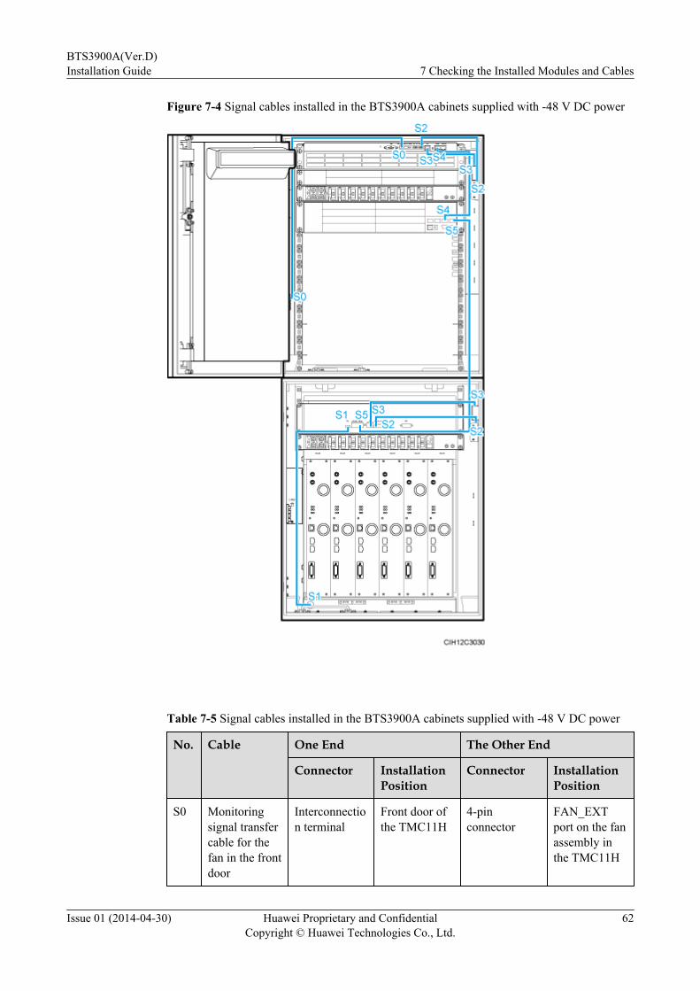
Figure 7-4 Signal cables installed in the BTS3900A cabinets supplied with -48 V DC power
Table 7-5 Signal cables installed in the BTS3900A cabinets supplied with -48 V DC power
No. Cable One End The Other End
Connector InstallationPosition
Connector InstallationPosition
S0 Monitoringsignal transfercable for thefan in the frontdoor
Interconnection terminal
Front door ofthe TMC11H
4-pinconnector
FAN_EXTport on the fanassembly inthe TMC11H
BTS3900A(Ver.D)Installation Guide 7 Checking the Installed Modules and Cables
Issue 01 (2014-04-30) Huawei Proprietary and ConfidentialCopyright © Huawei Technologies Co., Ltd.
62

No. Cable One End The Other End
Connector InstallationPosition
Connector InstallationPosition
S1 Monitoringsignal cable forthetemperaturesensor in theRFC
4-pinconnector
TEM port onthe fanassembly inthe RFC
Temperaturesensor
Air intake ventat the bottomof the RFC
S2 Monitoringsignal cable forthe door statussensor
Bare wire GATE port onthe fanassembly inthe TMC11Hor RFC
Bare wire Door statussensor in theTMC11H orRFC
S3 ELU signalcable
RJ45connector
ELU in theTMC11H orRFC
RJ45connector
ELU port onthe fanassembly ofthe TMC11Hor RFC
S4 BBU-CMUEAmonitoringsignal cable inthe TMC11H
RJ45connector
COM_IN porton the fanassembly inthe TMC11H
RJ45connector
MON1 port onthe UPEU inthe BBU in theTMC11H
S5 BBU-CMUEAmonitoringsignal cable inthe RFC
RJ45connector
COM_IN porton the fanassembly inthe RFC
RJ45connector
MON0 port onthe UPEU inthe BBU in theTMC11H
Step 4 Check whether signal cables are connected securely and correctly in the cabinets according tothe following table.
NOTE
For the transmission cable connections of various RATs in various transmission modes, see TransmissionCable Connections in 3900 Series Base Station Cables.
BTS3900A(Ver.D)Installation Guide 7 Checking the Installed Modules and Cables
Issue 01 (2014-04-30) Huawei Proprietary and ConfidentialCopyright © Huawei Technologies Co., Ltd.
63

Table 7-6 Transmission cables installed in the BTS3900A
Cable One End The Other End
Connector InstallationPosition
Connector InstallationPosition
E1/T1 surgeprotectiontransfer cable
DB26connector
E1/T1 port on theGTMU, WMPT,UMPT, or UTRP inthe BBU
DB25connector
INSIDE port on theUELP in the SLPU
FE/GE surgeprotectiontransfer cable
RJ45connector
l FE electrical porton the GTMU,WMPT, orUMPT in theBBU
l FE electrical porton the LMPT orUMPT in theBBU
RJ45connector
FE electrical port nearthe INSIDEsilkscreen on theUFLP in the SLPU
Interconnection cablebetween FEoptical ports
LCconnector
FE optical port on theGTMU, WMPT,UMPT, LMPT in theBBU
LCconnector
FE optical port on theWMPT, UMPT,LMPT, or GTMU inthe BBU
Interconnection cablebetween FEelectricalports
RJ45connector
FE electrical port onthe GTMU, WMPT,UMPT, LMPT in theBBU
RJ45connector
FE electrical port onthe WMPT, UMPT,LMPT, or GTMU inthe BBU
Step 5 CPRI electrical cables have been installed in the cabinets as required before delivery. You needto check whether the cables are connected securely. For details about how to install or removeCPRI electrical cables, see Inserting and Removing CPRI Cables.
----End
BTS3900A(Ver.D)Installation Guide 7 Checking the Installed Modules and Cables
Issue 01 (2014-04-30) Huawei Proprietary and ConfidentialCopyright © Huawei Technologies Co., Ltd.
64
8 Installing the Base
This section describes the procedure and precautions for installing the base for a cabinet on aconcrete floor.
ContextFor the procedure for installing an IBBS700D/IBBS700T on a base at a BTS3900A (Ver.D) site,see Installing the Base in IBBS700D&IBBS700T User Guide.
Procedure
Step 1 Install the base in the correct position.1. Determine the position to install the cabinet according to the engineering drawing and 2.4
Installation Clearance Requirements.2. Mark anchor points on the concrete pad, as shown by the circles in the following figure.
BTS3900A(Ver.D)Installation Guide 8 Installing the Base
Issue 01 (2014-04-30) Huawei Proprietary and ConfidentialCopyright © Huawei Technologies Co., Ltd.
65

Figure 8-1 Anchor points for the base
(1) Wall (2) Installation holes
3. After drawing the lines between anchor points, use a long measuring tape to measure the
distance between anchor points to ensure that the dimensions are accurate.
Step 2 Drill holes at the anchor points and install expansion bolt assemblies in the holes, as shown inthe following figure.
CAUTIONTake proper safety measures to protect your eyes and respiratory tract against the dust beforedrilling holes.
NOTE
Generally, the concrete floor is solid and smooth. Therefore, you can use the center punch to help locatethe drill bit. If the conditions of the floor allow direct drilling, skip this step.
BTS3900A(Ver.D)Installation Guide 8 Installing the Base
Issue 01 (2014-04-30) Huawei Proprietary and ConfidentialCopyright © Huawei Technologies Co., Ltd.
66
Figure 8-2 Drilling a hole and inserting an expansion bolt assembly
(1) M12x60 bolts (2) Spring washer (3) Flat washer (4) Expansion tube
1. Use a hammer drill with a Φ16 drill bit to drill holes with a depth ranging from 52 mm(2.05 in.) to 60 mm (2.36 in.).
2. Use a vacuum cleaner to clear the dust out from inside and around the holes, and measurethe distances between holes. If any of the hole is beyond the acceptable range, mark a newanchor point and drill a new hole.
3. Tighten an expansion bolt slightly and place it vertically into each hole.
4. Hit the expansion bolt with a rubber mallet until the expansion tube completely enters thehole.
5. Turning the M12x60 bolt, spring washer, and flat washer counterclockwise, and removethem in sequence.
CAUTIONAfter dismantling the expansion bolt assembly, ensure that the top of the expansion tubeis level with the concrete floor. Otherwise, the cabinet cannot be installed on the concretefloor evenly and securely.
Step 3 Place the base on the concrete pad, as shown in the following figure.
BTS3900A(Ver.D)Installation Guide 8 Installing the Base
Issue 01 (2014-04-30) Huawei Proprietary and ConfidentialCopyright © Huawei Technologies Co., Ltd.
67
1. Place the base in the determined position on the concrete pad, using the expansion tubesas reference.
2. Insert the M12x60 bolts, spring washers, and flat washers, but do not tighten them.
Figure 8-3 Installing the base in the correct position
Step 4 Adjust the base until it is horizontally level, as shown in the following figure.
1. Place the level on the base and observe the position of the mercury.
2. The base is horizontal only when the mercury is in the center of the level. Add spacersbetween the base and the concrete pad to adjust the level if necessary.
Figure 8-4 Adjusting the base until it is horizontally level
(1) Level (2) Spacer
BTS3900A(Ver.D)Installation Guide 8 Installing the Base
Issue 01 (2014-04-30) Huawei Proprietary and ConfidentialCopyright © Huawei Technologies Co., Ltd.
68

Step 5 Use a torque wrench to tighten the M12x60 bolts to 45 N·m (398.25 lbf·in.) in a diagonalsequence, as shown in the following figure.
Figure 8-5 Tightening the bolts
Step 6 Use a Phillips screwdriver to loosen the three M4 countersunk screws on the front cover plateof the base, and remove the front cover plate.
NOTE
Keep the removed screws and cover plates for later installation.
Figure 8-6 Remove the front cover plate
Step 7 Remove the baffle plates from both sides and the rear of the base, as shown in the followingfigure.
BTS3900A(Ver.D)Installation Guide 8 Installing the Base
Issue 01 (2014-04-30) Huawei Proprietary and ConfidentialCopyright © Huawei Technologies Co., Ltd.
69

1. Use a Phillips screwdriver to loosen the M4 screw assemblies on both sides of the base andremove the baffle plates.
2. Use a Phillips screwdriver to loosen the two M4 screw assemblies on the left of the rear ofthe base and slide the left baffle plate to the left. Then remove the baffle plates on the rightside one by one.
Figure 8-7 Removing the baffle plates from both sides and the rear of the base
Step 8 Optional: If an RFC will be installed on the base, the mounting blocks need to be fixed on thebase, and tighten the bolts to 45 N·m (398.25 lbf·in.), as shown in the following figure.
NOTE
The mounting blocks are placed in the accessory bag of the RFC.
BTS3900A(Ver.D)Installation Guide 8 Installing the Base
Issue 01 (2014-04-30) Huawei Proprietary and ConfidentialCopyright © Huawei Technologies Co., Ltd.
70
Figure 8-8 Securing the mounting blocks
(1) Bolt (2) Spring washer (3) Flat washer (4) Mounting block
----End
BTS3900A(Ver.D)Installation Guide 8 Installing the Base
Issue 01 (2014-04-30) Huawei Proprietary and ConfidentialCopyright © Huawei Technologies Co., Ltd.
71

9 Installing the Cabinet
About This Chapter
When installing the BTS3900A, use different installation modes based on different scenarios.
9.1 Installing the Cabinet on a BaseThis section describes the procedure and precautions for installing two stacked cabinets or asingle cabinet on a base.
9.2 Stacking Two CabinetsThis section describes the procedure and precautions for stacking a cabinet on another.
BTS3900A(Ver.D)Installation Guide 9 Installing the Cabinet
Issue 01 (2014-04-30) Huawei Proprietary and ConfidentialCopyright © Huawei Technologies Co., Ltd.
72
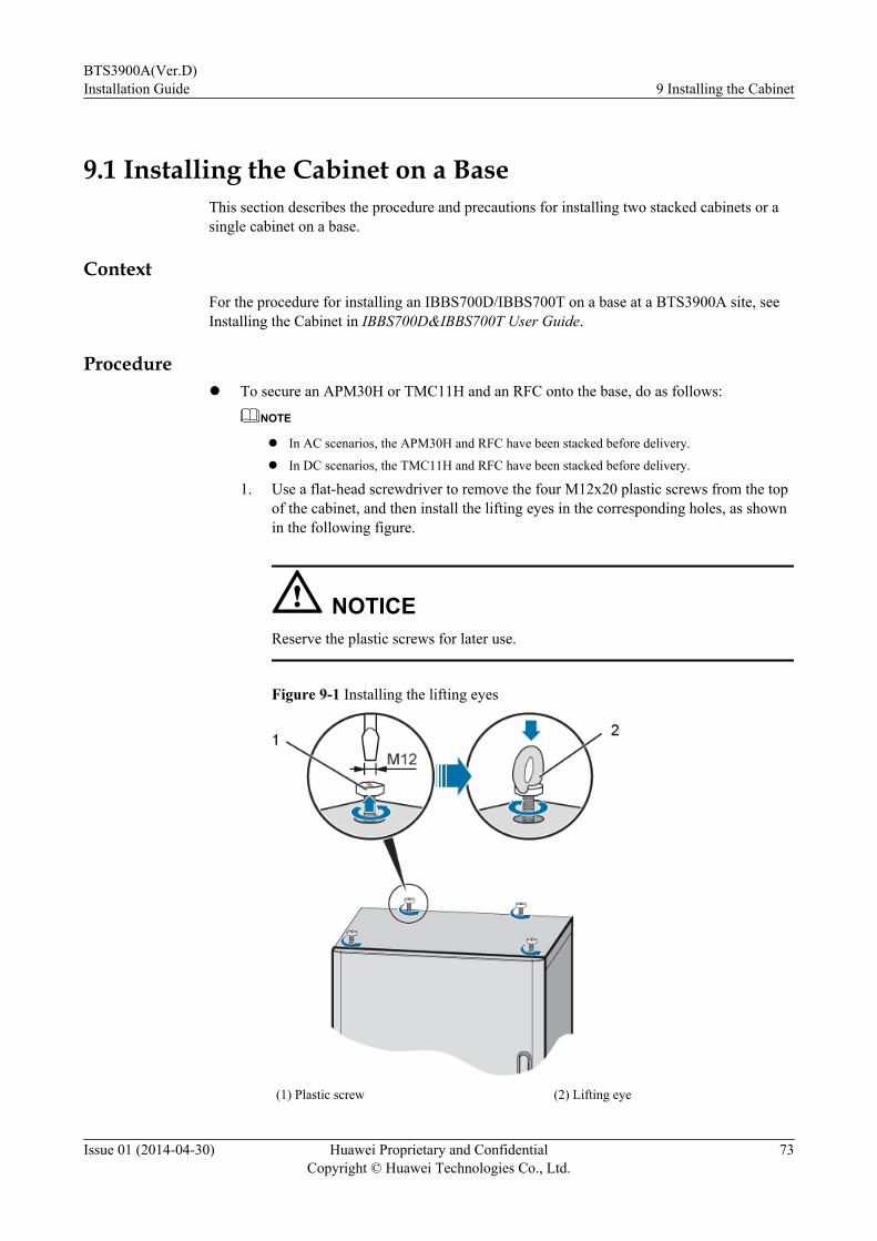
9.1 Installing the Cabinet on a BaseThis section describes the procedure and precautions for installing two stacked cabinets or asingle cabinet on a base.
ContextFor the procedure for installing an IBBS700D/IBBS700T on a base at a BTS3900A site, seeInstalling the Cabinet in IBBS700D&IBBS700T User Guide.
Procedurel To secure an APM30H or TMC11H and an RFC onto the base, do as follows:
NOTE
l In AC scenarios, the APM30H and RFC have been stacked before delivery.
l In DC scenarios, the TMC11H and RFC have been stacked before delivery.
1. Use a flat-head screwdriver to remove the four M12x20 plastic screws from the topof the cabinet, and then install the lifting eyes in the corresponding holes, as shownin the following figure.
NOTICEReserve the plastic screws for later use.
Figure 9-1 Installing the lifting eyes
(1) Plastic screw (2) Lifting eye
BTS3900A(Ver.D)Installation Guide 9 Installing the Cabinet
Issue 01 (2014-04-30) Huawei Proprietary and ConfidentialCopyright © Huawei Technologies Co., Ltd.
73
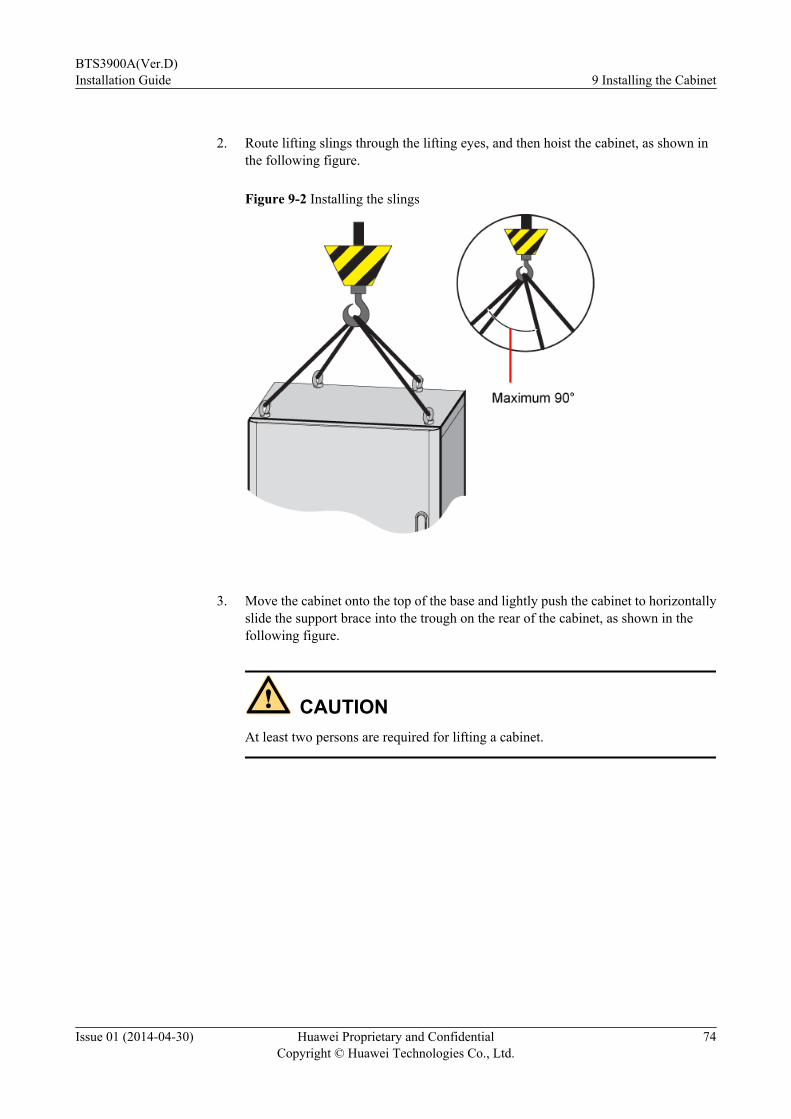
2. Route lifting slings through the lifting eyes, and then hoist the cabinet, as shown in
the following figure.
Figure 9-2 Installing the slings
3. Move the cabinet onto the top of the base and lightly push the cabinet to horizontally
slide the support brace into the trough on the rear of the cabinet, as shown in thefollowing figure.
CAUTIONAt least two persons are required for lifting a cabinet.
BTS3900A(Ver.D)Installation Guide 9 Installing the Cabinet
Issue 01 (2014-04-30) Huawei Proprietary and ConfidentialCopyright © Huawei Technologies Co., Ltd.
74

Figure 9-3 Lifting a cabinet onto a base
4. Remove the slings and use a flat-head screwdriver to secure the four M12x20 plastic
screws on the top of the cabinet, as shown in the following figure.
NOTICEBefore installing the plastic screws, clean the mounting holes to prevent entry of metalbits.
BTS3900A(Ver.D)Installation Guide 9 Installing the Cabinet
Issue 01 (2014-04-30) Huawei Proprietary and ConfidentialCopyright © Huawei Technologies Co., Ltd.
75
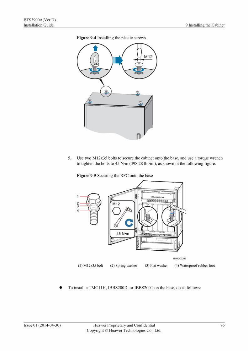
Figure 9-4 Installing the plastic screws
5. Use two M12x35 bolts to secure the cabinet onto the base, and use a torque wrench
to tighten the bolts to 45 N·m (398.28 lbf·in.), as shown in the following figure.
Figure 9-5 Securing the RFC onto the base
(1) M12x35 bolt (2) Spring washer (3) Flat washer (4) Waterproof rubber foot
l To install a TMC11H, IBBS200D, or IBBS200T on the base, do as follows:
BTS3900A(Ver.D)Installation Guide 9 Installing the Cabinet
Issue 01 (2014-04-30) Huawei Proprietary and ConfidentialCopyright © Huawei Technologies Co., Ltd.
76
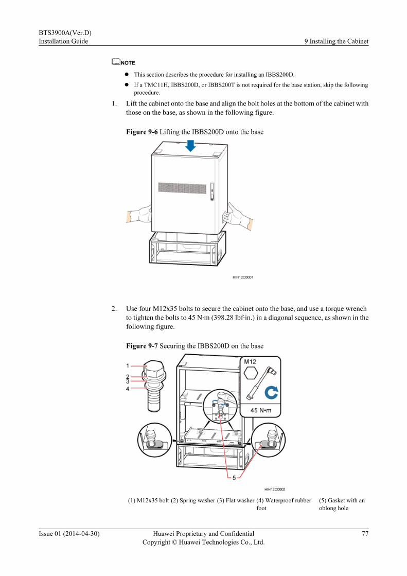
NOTE
l This section describes the procedure for installing an IBBS200D.
l If a TMC11H, IBBS200D, or IBBS200T is not required for the base station, skip the followingprocedure.
1. Lift the cabinet onto the base and align the bolt holes at the bottom of the cabinet withthose on the base, as shown in the following figure.
Figure 9-6 Lifting the IBBS200D onto the base
2. Use four M12x35 bolts to secure the cabinet onto the base, and use a torque wrench
to tighten the bolts to 45 N·m (398.28 lbf·in.) in a diagonal sequence, as shown in thefollowing figure.
Figure 9-7 Securing the IBBS200D on the base
(1) M12x35 bolt (2) Spring washer (3) Flat washer (4) Waterproof rubberfoot
(5) Gasket with anoblong hole
BTS3900A(Ver.D)Installation Guide 9 Installing the Cabinet
Issue 01 (2014-04-30) Huawei Proprietary and ConfidentialCopyright © Huawei Technologies Co., Ltd.
77
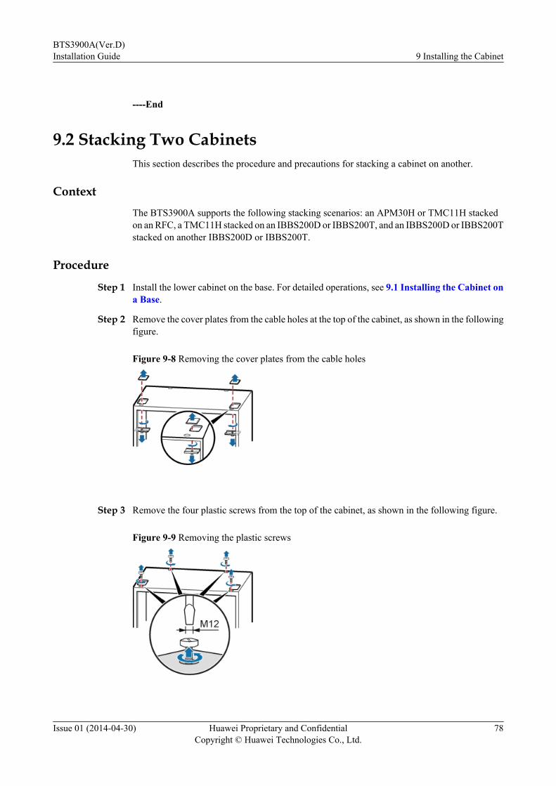
----End
9.2 Stacking Two CabinetsThis section describes the procedure and precautions for stacking a cabinet on another.
ContextThe BTS3900A supports the following stacking scenarios: an APM30H or TMC11H stackedon an RFC, a TMC11H stacked on an IBBS200D or IBBS200T, and an IBBS200D or IBBS200Tstacked on another IBBS200D or IBBS200T.
Procedure
Step 1 Install the lower cabinet on the base. For detailed operations, see 9.1 Installing the Cabinet ona Base.
Step 2 Remove the cover plates from the cable holes at the top of the cabinet, as shown in the followingfigure.
Figure 9-8 Removing the cover plates from the cable holes
Step 3 Remove the four plastic screws from the top of the cabinet, as shown in the following figure.
Figure 9-9 Removing the plastic screws
BTS3900A(Ver.D)Installation Guide 9 Installing the Cabinet
Issue 01 (2014-04-30) Huawei Proprietary and ConfidentialCopyright © Huawei Technologies Co., Ltd.
78
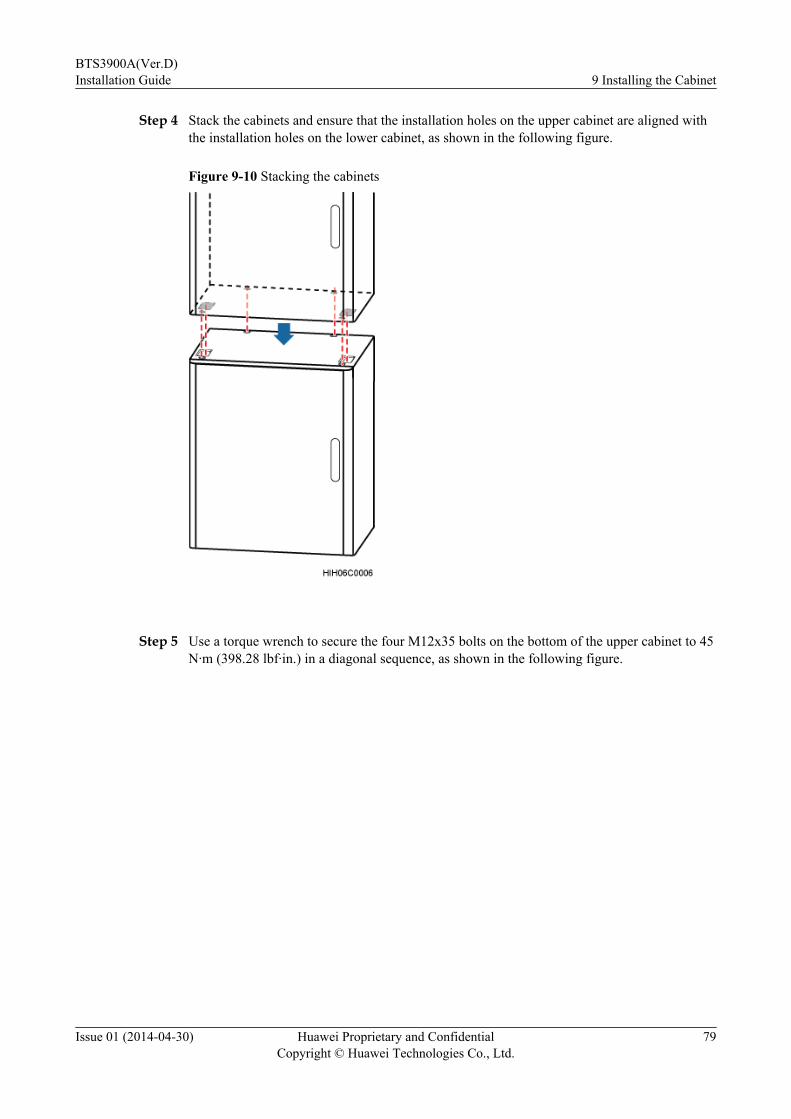
Step 4 Stack the cabinets and ensure that the installation holes on the upper cabinet are aligned withthe installation holes on the lower cabinet, as shown in the following figure.
Figure 9-10 Stacking the cabinets
Step 5 Use a torque wrench to secure the four M12x35 bolts on the bottom of the upper cabinet to 45N·m (398.28 lbf·in.) in a diagonal sequence, as shown in the following figure.
BTS3900A(Ver.D)Installation Guide 9 Installing the Cabinet
Issue 01 (2014-04-30) Huawei Proprietary and ConfidentialCopyright © Huawei Technologies Co., Ltd.
79

Figure 9-11 Tightening the bolts
(1) M12x35 bolt (2) Spring washer (3) Flat washer (4) Waterproof rubber foot (5) Gasket with an oblonghole
----End
BTS3900A(Ver.D)Installation Guide 9 Installing the Cabinet
Issue 01 (2014-04-30) Huawei Proprietary and ConfidentialCopyright © Huawei Technologies Co., Ltd.
80
10 Installing a PGND Cable and anEquipotential Cable
A PGND cable connects a PGND screw in a cabinet and a PGND bar to ensure proper groundingof the cabinet. An equipotential cable connects PGND screws on different cabinets to ensure theequipotential bonding between the cabinets.
PrerequisitesThe following tools and materials are available: a Phillips screwdriver, a torque screwdriver,and a pair of ESD gloves.
ContextThe principles for grounding the BTS3900A site are as follows:l The upper and lower cabinets must be connected through an equipotential cable.l The lower cabinets are connected to the RFC through the equipotential cables.l The RFC is connected to the ground busbar through the PGND cable.
The following table lists the specifications of a PGND cable and an equipotential cable.
Table 10-1 Specifications of a PGND cable and an equipotential cable
Cable Cross-Sectional Area ofthe Cable and Size of theOT Terminal
Color
PGND cable OT terminal (M6, 16 mm2 or0.025 in.2)
l 220 V AC or -48 V DC input: greenand yellow
l 110 V AC input: greenEquipotentialcable
OT terminal (M6, 16 mm2 or0.025 in.2)
BTS3900A(Ver.D)Installation Guide 10 Installing a PGND Cable and an Equipotential Cable
Issue 01 (2014-04-30) Huawei Proprietary and ConfidentialCopyright © Huawei Technologies Co., Ltd.
81

Procedure
Step 1 Prepare a PGND cable.1. Cut the cables to the length suitable for the actual cable route.2. Add OT terminals to both ends of the cables according to the instructions in Assembling
the OT Terminal and the Power Cable.
Step 2 Install the PGND cable, as shown in Figure 10-2.1. Connect one end of the PGND cable to the ground bar on the inner wall of the RFC, and
then use spring washers and screws to secure the OT terminals of the PGND cable.
NOTE
When installing a PGND cable, tightly press the OT terminal in the correct direction, as shown inFigure 10-1.
Figure 10-1 Installing an OT terminal correctly
2. Connect the other end of the PGND cable to the external ground copper bar outside the
cabinet, as shown in the following figure.
BTS3900A(Ver.D)Installation Guide 10 Installing a PGND Cable and an Equipotential Cable
Issue 01 (2014-04-30) Huawei Proprietary and ConfidentialCopyright © Huawei Technologies Co., Ltd.
82

Figure 10-2 Installing a PGND cable
(1) Ground bar in the cabinet (2) PGND cable (3) Onsite ground bar
Step 3 Install an equipotential cable.
Figure 10-3, Figure 10-4, and Figure 10-5 show the positions for installing equipotential cablesin the cabinets. For the detailed procedure, go to Step 2.
Figure 10-3 Installing an equipotential cable (scenario 1)
BTS3900A(Ver.D)Installation Guide 10 Installing a PGND Cable and an Equipotential Cable
Issue 01 (2014-04-30) Huawei Proprietary and ConfidentialCopyright © Huawei Technologies Co., Ltd.
83
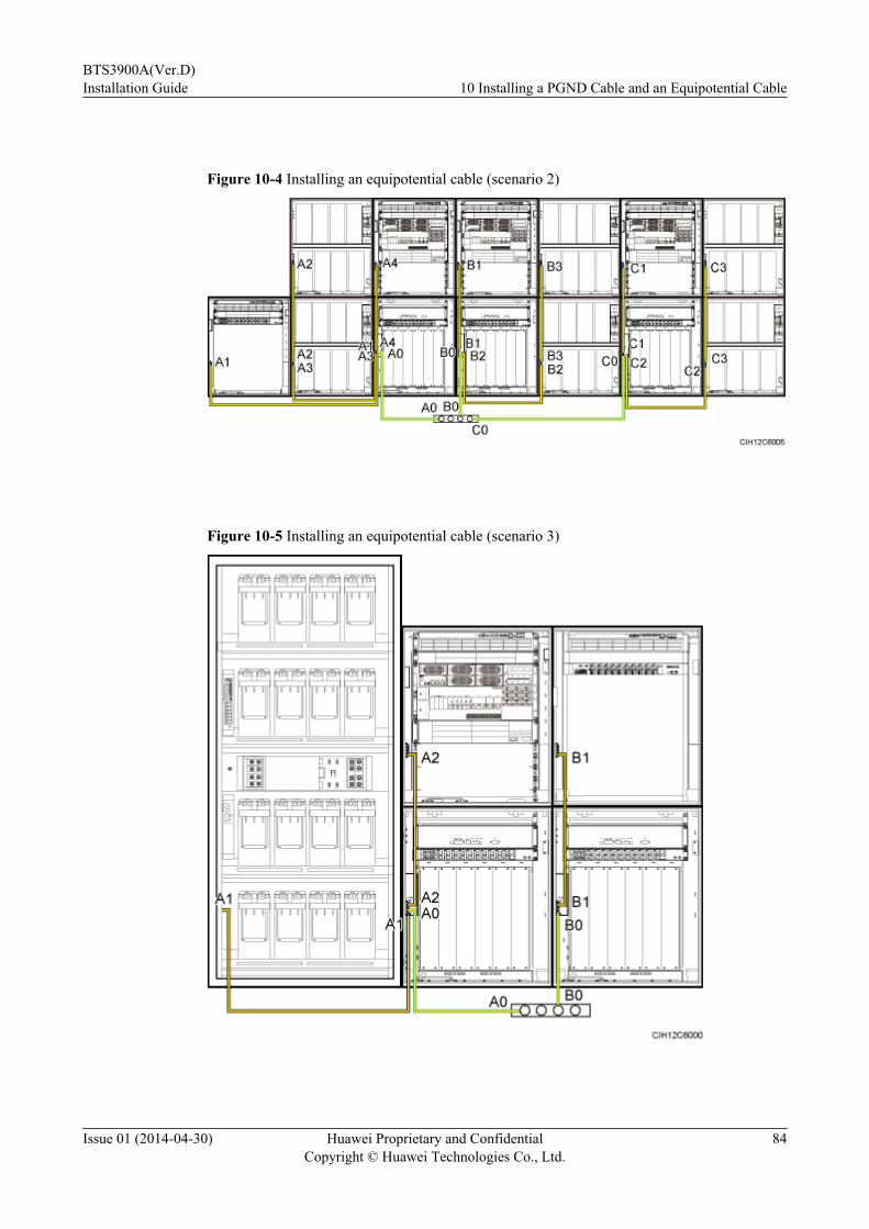
Figure 10-4 Installing an equipotential cable (scenario 2)
Figure 10-5 Installing an equipotential cable (scenario 3)
BTS3900A(Ver.D)Installation Guide 10 Installing a PGND Cable and an Equipotential Cable
Issue 01 (2014-04-30) Huawei Proprietary and ConfidentialCopyright © Huawei Technologies Co., Ltd.
84
Step 4 Lay out the cables according to the instructions in 12.1 Cabling Requirements, and use cableties to bind them.
Step 5 Label the installed cables according to the instructions in Attaching a Sign Plate Label.
----End
BTS3900A(Ver.D)Installation Guide 10 Installing a PGND Cable and an Equipotential Cable
Issue 01 (2014-04-30) Huawei Proprietary and ConfidentialCopyright © Huawei Technologies Co., Ltd.
85
11 Installing Optional Modules and TheirCables
About This Chapter
This chapter describes procedures for installing the optional modules and their cables onsite.
11.1 Installing the SLPU as a Monitoring Signal Protection UnitWhen an outdoor base station uses 1 to 16 customerized alarm inputs, you need to install theSLPU as a monitoring signal protection unit and its cables.
11.2 Installing the EMUA/EMUB and Its CablesThis section describes the procedure for installing the EMUA/EMUB and its cables in differentcabinets.
11.3 Installing the GPS Surge ProtectorThe GPS surge protector can be installed at a site to provide surge protection for GPS signals.
11.4 Installing the GATM and Bias-TeeIf the DRFU is installed at a site, the GATM and Bias-Tee must be installed at the site.
11.5 Installing the DDFThe digital distribution frame (DDF) distributes alarm cables and E1/T1 cables.
11.6 Installing the BatteriesThis section describes the procedure and precautions for installing the batteries and related cablesin the IBBS200D, IBBS200T, IBBS700D, and IBBS700T.
11.7 Installing the DCDU-12BYou need to install the DCDU-12B and its cables when RRUs are added to a base stationconfigured only with RFUs.
11.8 Installing the BBUWhen a site is configured with RFUs and RRUs, you need to install a second BBU and its cables.
11.9 Installing Boards in the BBU and surge protection boardsWhen an outdoor base station originally configured with RFUs is expanded to support RFUsand RRUs, BBU boards and surge protection boards need to be installed onsite. When an indoor
BTS3900A(Ver.D)Installation Guide 11 Installing Optional Modules and Their Cables
Issue 01 (2014-04-30) Huawei Proprietary and ConfidentialCopyright © Huawei Technologies Co., Ltd.
86

base station originally configured with RFUs is expanded to support RFUs and RRUs, only BBUboards need to be installed onsite.
11.10 Installing the RFUIf the RFUs initially configured for the base station do not reach the full configuration, you canadd RFUs based on the site requirements.
11.11 Installing the RRUIf a site is configured with RFUs and RRUs, the RRUs and their cables must be installed onsite.For details, see the related RRU installation guide.
11.12 Installing the AC HeaterWhen the environmental temperature of a cabinet is low, the cabinet can be configured with aheater so that the temperature in the cabinet is kept in a proper range. This section describes theprocedure for installing a heater in an APM30H or TMC11H.
11.13 (Optional) Installing the HAU01A-01This section describes the procedure and precautions for installing the HAU01A-01 and itsrelated cables.
BTS3900A(Ver.D)Installation Guide 11 Installing Optional Modules and Their Cables
Issue 01 (2014-04-30) Huawei Proprietary and ConfidentialCopyright © Huawei Technologies Co., Ltd.
87

11.1 Installing the SLPU as a Monitoring Signal ProtectionUnit
When an outdoor base station uses 1 to 16 customerized alarm inputs, you need to install theSLPU as a monitoring signal protection unit and its cables.
Contextl The following table lists the specifications of the cables for the SLPU.
Table 11-1 Cable specifications
Cable One End The Other End Remarks
Surge protectiontransfer cable forthe monitoringsignals
RJ45 connector RJ45 connector Gray shieldedstraight-throughcable
External dry contactmonitoring signalcable
Bare wire Depending on theexternal equipment
-
l The SLPU is installed in the 1 U space under the BBU.
Procedure
Step 1 Select the step according to the types of the APM30H.
If... Then...
An APM30H(Ver.B), APM30H(Ver.C), TMC11H(Ver.B), or TMC11H(Ver.C) is used
Go toStep 2.
An APM30H(Ver.D) or TMC11H(Ver.D) is used Go toStep 3.
Step 2 Optional: If there is a filler module in the installation position, remove the filler module, asshown in the following figure.
1. Use a Phillips screwdriver to remove the two M6 screws from the mounting ear on eachside of the filler module.
2. Slide the filler module out of the cabinet.
NOTE
The removed filler modules must be installed in the vacant slots in the lower part of the cabinet from top down.If vacant slots are all occupied with filler modules, other redundant filler modules are discarded.
BTS3900A(Ver.D)Installation Guide 11 Installing Optional Modules and Their Cables
Issue 01 (2014-04-30) Huawei Proprietary and ConfidentialCopyright © Huawei Technologies Co., Ltd.
88
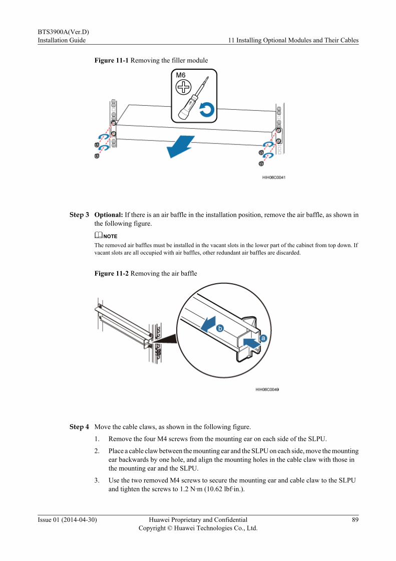
Figure 11-1 Removing the filler module
Step 3 Optional: If there is an air baffle in the installation position, remove the air baffle, as shown inthe following figure.
NOTE
The removed air baffles must be installed in the vacant slots in the lower part of the cabinet from top down. Ifvacant slots are all occupied with air baffles, other redundant air baffles are discarded.
Figure 11-2 Removing the air baffle
Step 4 Move the cable claws, as shown in the following figure.
1. Remove the four M4 screws from the mounting ear on each side of the SLPU.
2. Place a cable claw between the mounting ear and the SLPU on each side, move the mountingear backwards by one hole, and align the mounting holes in the cable claw with those inthe mounting ear and the SLPU.
3. Use the two removed M4 screws to secure the mounting ear and cable claw to the SLPUand tighten the screws to 1.2 N·m (10.62 lbf·in.).
BTS3900A(Ver.D)Installation Guide 11 Installing Optional Modules and Their Cables
Issue 01 (2014-04-30) Huawei Proprietary and ConfidentialCopyright © Huawei Technologies Co., Ltd.
89

Figure 11-3 Moving the cable claw on the SLPU
Step 5 Slide the SLPU into the cabinet and use a torque screwdriver to tighten the two M6x12 screwson the mounting ears to 2 N·m (17.7 lbf·in.), as shown in the following figure.
Figure 11-4 Installing the SLPU
Step 6 Install the surge protection transfer cable for the monitoring signals, as shown in the followingfigure.
1. Connect one end of the cable to the OUT0 port on the USLP2 in slot 3 of the SLPU.
2. Connect the other end of the cable to the EXT_ALM0 port on the UPEU in the BBU.
BTS3900A(Ver.D)Installation Guide 11 Installing Optional Modules and Their Cables
Issue 01 (2014-04-30) Huawei Proprietary and ConfidentialCopyright © Huawei Technologies Co., Ltd.
90

Figure 11-5 Installing the surge protection transfer cable for the monitoring signals
NOTE
A maximum of three surge protection transfer cables for the monitoring signals are installed according tothe actually customerized alarm inputs, as shown in the following figure. For details about the customerizedalarm inputs and cable connections, see section "Customized Alarm Input Principles" in the correspondinghardware description.
Figure 11-6 Connections of the surge protection transfer cable for the monitoring signals
Step 7 Install external dry contact monitoring signal cable, as shown in the following figure.1. Cut the external dry contact monitoring signal cable to the length suitable for the actual
cable route.2. Strip an 8 mm (0.31 in) length of the jacket off the cable connected to the USLP2 to expose
the wires.3. Use a screwdriver to press the IN0 to IN3 ports on the USLP, insert the external dry contact
monitoring signal cables into the ports, and move the screwdriver away.
BTS3900A(Ver.D)Installation Guide 11 Installing Optional Modules and Their Cables
Issue 01 (2014-04-30) Huawei Proprietary and ConfidentialCopyright © Huawei Technologies Co., Ltd.
91
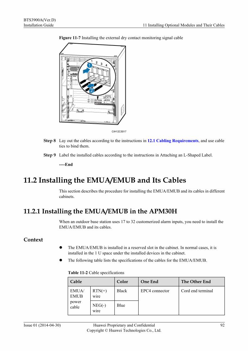
Figure 11-7 Installing the external dry contact monitoring signal cable
Step 8 Lay out the cables according to the instructions in 12.1 Cabling Requirements, and use cableties to bind them.
Step 9 Label the installed cables according to the instructions in Attaching an L-Shaped Label.
----End
11.2 Installing the EMUA/EMUB and Its CablesThis section describes the procedure for installing the EMUA/EMUB and its cables in differentcabinets.
11.2.1 Installing the EMUA/EMUB in the APM30HWhen an outdoor base station uses 17 to 32 customerized alarm inputs, you need to install theEMUA/EMUB and its cables.
Contextl The EMUA/EMUB is installed in a reserved slot in the cabinet. In normal cases, it is
installed in the 1 U space under the installed devices in the cabinet.
l The following table lists the specifications of the cables for the EMUA/EMUB.
Table 11-2 Cable specifications
Cable Color One End The Other End
EMUA/EMUBpowercable
RTN(+)wire
Black EPC4 connector Cord end terminal
NEG(-)wire
Blue
BTS3900A(Ver.D)Installation Guide 11 Installing Optional Modules and Their Cables
Issue 01 (2014-04-30) Huawei Proprietary and ConfidentialCopyright © Huawei Technologies Co., Ltd.
92
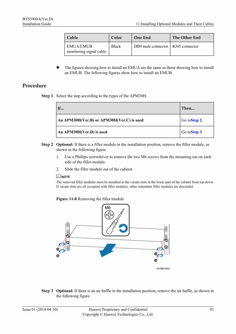
Cable Color One End The Other End
EMUA/EMUBmonitoring signal cable
Black DB9 male connector RJ45 connector
l The figures showing how to install an EMUA are the same as those showing how to installan EMUB. The following figures show how to install an EMUB.
Procedure
Step 1 Select the step according to the types of the APM30H.
If... Then...
An APM30H(Ver.B) or APM30H(Ver.C) is used Go toStep 2.
An APM30H(Ver.D) is used Go toStep 3.
Step 2 Optional: If there is a filler module in the installation position, remove the filler module, asshown in the following figure.
1. Use a Phillips screwdriver to remove the two M6 screws from the mounting ear on eachside of the filler module.
2. Slide the filler module out of the cabinet.
NOTE
The removed filler modules must be installed in the vacant slots in the lower part of the cabinet from top down.If vacant slots are all occupied with filler modules, other redundant filler modules are discarded.
Figure 11-8 Removing the filler module
Step 3 Optional: If there is an air baffle in the installation position, remove the air baffle, as shown inthe following figure.
BTS3900A(Ver.D)Installation Guide 11 Installing Optional Modules and Their Cables
Issue 01 (2014-04-30) Huawei Proprietary and ConfidentialCopyright © Huawei Technologies Co., Ltd.
93

NOTE
The removed air baffles must be installed in the vacant slots in the lower part of the cabinet from top down. Ifvacant slots are all occupied with air baffles, other redundant air baffles are discarded.
Figure 11-9 Removing the air baffle
Step 4 Optional: Align the cable claws with the holes of the mounting ears on the EMUB, and stickthe cable claws onto both sides of the EMUB, as shown in the following figure. If you want toinstall an EMUA, skip this step.
Figure 11-10 Sticking cable claws onto both sides of an EMUB
(1) Double-sided tape
Step 5 Install the EMUA/EMUB, as shown in the following figure.
1. Slide the EMUA/EMUB into the installation position.
2. Tighten the four M6 screws on the mounting ear on both sides of the EMUA/EMUB to 2N·m (17.7 lbf·in.).
BTS3900A(Ver.D)Installation Guide 11 Installing Optional Modules and Their Cables
Issue 01 (2014-04-30) Huawei Proprietary and ConfidentialCopyright © Huawei Technologies Co., Ltd.
94
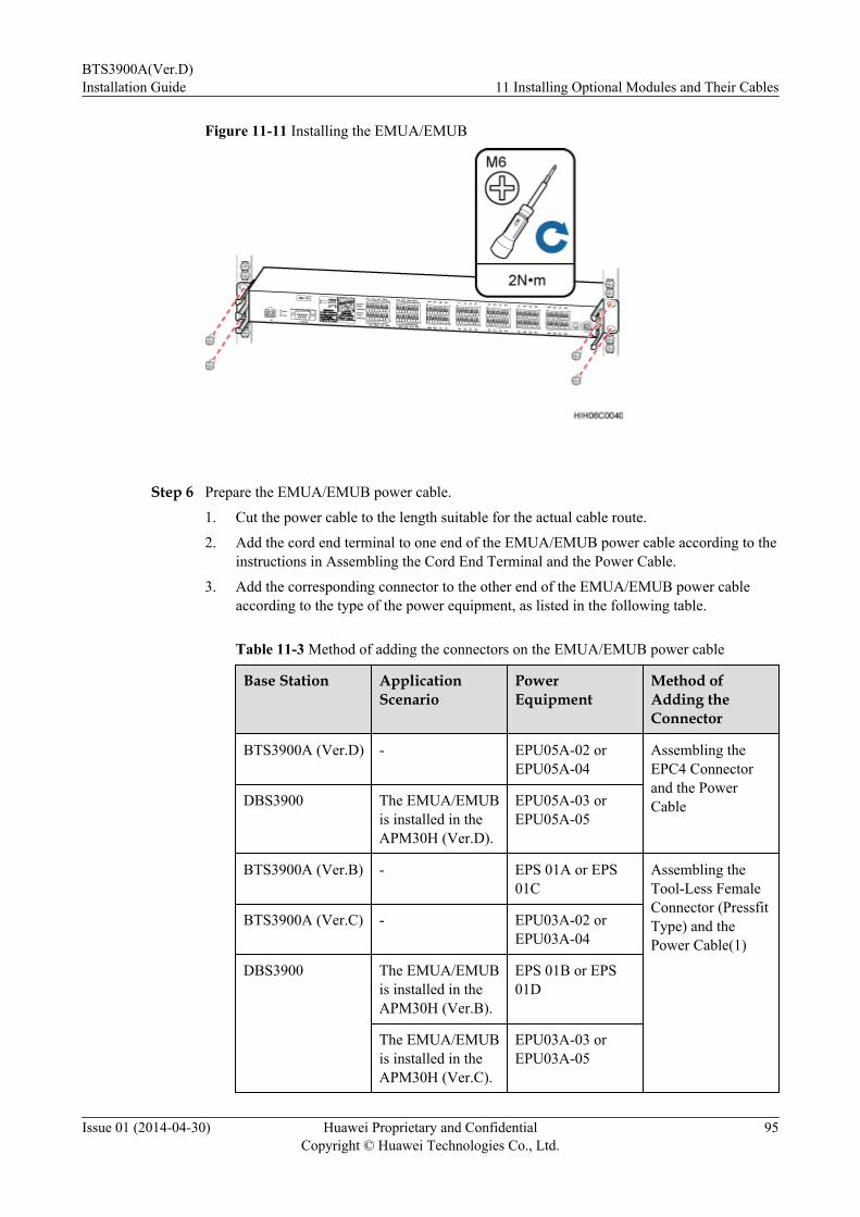
Figure 11-11 Installing the EMUA/EMUB
Step 6 Prepare the EMUA/EMUB power cable.
1. Cut the power cable to the length suitable for the actual cable route.
2. Add the cord end terminal to one end of the EMUA/EMUB power cable according to theinstructions in Assembling the Cord End Terminal and the Power Cable.
3. Add the corresponding connector to the other end of the EMUA/EMUB power cableaccording to the type of the power equipment, as listed in the following table.
Table 11-3 Method of adding the connectors on the EMUA/EMUB power cable
Base Station ApplicationScenario
PowerEquipment
Method ofAdding theConnector
BTS3900A (Ver.D) - EPU05A-02 orEPU05A-04
Assembling theEPC4 Connectorand the PowerCableDBS3900 The EMUA/EMUB
is installed in theAPM30H (Ver.D).
EPU05A-03 orEPU05A-05
BTS3900A (Ver.B) - EPS 01A or EPS01C
Assembling theTool-Less FemaleConnector (PressfitType) and thePower Cable(1)
BTS3900A (Ver.C) - EPU03A-02 orEPU03A-04
DBS3900 The EMUA/EMUBis installed in theAPM30H (Ver.B).
EPS 01B or EPS01D
The EMUA/EMUBis installed in theAPM30H (Ver.C).
EPU03A-03 orEPU03A-05
BTS3900A(Ver.D)Installation Guide 11 Installing Optional Modules and Their Cables
Issue 01 (2014-04-30) Huawei Proprietary and ConfidentialCopyright © Huawei Technologies Co., Ltd.
95
Step 7 Install the EMUA/EMUB power cable, as shown in the following figure.1. Connect the cord end terminal at one end of the EMUA/EMUB power cable to the PWR1
port on the EMUA/EMUB.2. Connect the other end of the cable to the corresponding power equipment, as listed in the
following table.
Table 11-4 Installation position of the EMUA/EMUB power cable
Base Station ApplicationScenario
PowerEquipment
InstallationPosition
BTS3900A (Ver.B) - EPS 01A or EPS01C
DC output terminalLOAD7
DBS3900 The EMUA/EMUBis installed in theAPM30H (Ver.B).
EPS 01B or EPS01D
BTS3900A (Ver.C) - EPU03A-02 orEPU03A-04
DC output terminalLOAD4
DBS3900 The EMUA/EMUBis installed in theAPM30H (Ver.C).
EPU03A-03 orEPU03A-05
BTS3900A (Ver.D) - EPU05A-02 orEPU05A-04
DC output fuseterminal LOAD5
DBS3900 The EMUA/EMUBis installed in theAPM30H (Ver.D).
EPU05A-03 orEPU05A-05
BTS3900A(Ver.D)Installation Guide 11 Installing Optional Modules and Their Cables
Issue 01 (2014-04-30) Huawei Proprietary and ConfidentialCopyright © Huawei Technologies Co., Ltd.
96

Figure 11-12 Installing the EMUA/EMUB power cable
3. Lay out the cables according to the instructions in 12.1 Cabling Requirements, and use
cable ties to bind them.4. Label the installed cables according to the instructions in Attaching a Cable-Tying Label.
Step 8 Install the EMUA/EMUB monitoring signal cable, as shown in the following figure.1. Connect one end of the cable with a DB9 male connector to the RS-485 port on the EMUA
or the COM_485 port on the EMUB.2. Connect the RJ-45 connector at the other end of the cable to the COM_OUT port on the
PMU in the cabinet.
BTS3900A(Ver.D)Installation Guide 11 Installing Optional Modules and Their Cables
Issue 01 (2014-04-30) Huawei Proprietary and ConfidentialCopyright © Huawei Technologies Co., Ltd.
97

Figure 11-13 Installing the EMUA/EMUB monitoring signal cable
3. Lay out the cables according to the instructions in 12.1 Cabling Requirements, and usecable ties to bind them.
4. Label the installed cables according to the instructions in Attaching an L-Shaped Label.
----End
11.2.2 Installing the EMUA/EMUB in the TMC11HWhen an outdoor base station uses 17 to 32 customerized alarm inputs, you need to install theEMUA/EMUB and its cables.
Contextl The EMUA/EMUB is installed in a reserved slot in the cabinet. In normal cases, it is
installed in the 1 U space under the installed devices in the cabinet.
l The following table lists the specifications of the cables for the EMUA/EMUB.
Table 11-5 Cable specifications
Cable Color One End The Other End
EMUA/EMUBpowercable
RTN(+)wire
Black EPC4 connector Cord end terminal
NEG(-)wire
Blue
EMUA/EMUBmonitoring signal cable
Black DB9 male connector RJ45 connector
BTS3900A(Ver.D)Installation Guide 11 Installing Optional Modules and Their Cables
Issue 01 (2014-04-30) Huawei Proprietary and ConfidentialCopyright © Huawei Technologies Co., Ltd.
98

l The figures showing how to install an EMUA are the same as those showing how to installan EMUB. The following figures show how to install an EMUB.
Procedure
Step 1 Select the step according to the types of the TMC11H.
If... Then...
An TMC11H(Ver.B) or TMC11H(Ver.C) is used Go toStep 2.
An TMC11H(Ver.D) is used Go toStep 3.
Step 2 Optional: If there is a filler module in the installation position, remove the filler module, asshown in the following figure.
1. Use a Phillips screwdriver to remove the two M6 screws from the mounting ear on eachside of the filler module.
2. Slide the filler module out of the cabinet.
NOTE
The removed filler modules must be installed in the vacant slots in the lower part of the cabinet from top down.If vacant slots are all occupied with filler modules, other redundant filler modules are discarded.
Figure 11-14 Removing the filler module
Step 3 Optional: If there is an air baffle in the installation position, remove the air baffle, as shown inthe following figure.
NOTE
The removed air baffles must be installed in the vacant slots in the lower part of the cabinet from top down. Ifvacant slots are all occupied with air baffles, other redundant air baffles are discarded.
BTS3900A(Ver.D)Installation Guide 11 Installing Optional Modules and Their Cables
Issue 01 (2014-04-30) Huawei Proprietary and ConfidentialCopyright © Huawei Technologies Co., Ltd.
99
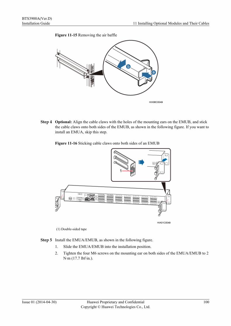
Figure 11-15 Removing the air baffle
Step 4 Optional: Align the cable claws with the holes of the mounting ears on the EMUB, and stickthe cable claws onto both sides of the EMUB, as shown in the following figure. If you want toinstall an EMUA, skip this step.
Figure 11-16 Sticking cable claws onto both sides of an EMUB
(1) Double-sided tape
Step 5 Install the EMUA/EMUB, as shown in the following figure.1. Slide the EMUA/EMUB into the installation position.2. Tighten the four M6 screws on the mounting ear on both sides of the EMUA/EMUB to 2
N·m (17.7 lbf·in.).
BTS3900A(Ver.D)Installation Guide 11 Installing Optional Modules and Their Cables
Issue 01 (2014-04-30) Huawei Proprietary and ConfidentialCopyright © Huawei Technologies Co., Ltd.
100

Figure 11-17 Installing the EMUA/EMUB
Step 6 Prepare the EMUA/EMUB power cable.1. Cut the power cable to the length suitable for the actual cable route.2. Add the cord end terminal to one end of the EMUA/EMUB power cable according to the
instructions in Assembling the Cord End Terminal and the Power Cable.3. Add the corresponding connector to the other end of the EMUA/EMUB power cable
according to the type of the power equipment, as listed in the following table.
Table 11-6 Method of adding the connectors on the EMUA/EMUB power cable
Base Station ApplicationScenario
PowerEquipment
Method ofAdding theConnector
BTS3900A (Ver.D) - DCDU-12C Assembling theEPC4 Connectorand the PowerCable
DBS3900 The EMUA/EMUBis installed in theTMC11H (Ver.D).
DCDU-12B
BTS3900A (Ver.C) - DCDU-11C Assembling theTool-Less FemaleConnector (PressfitType) and thePower Cable(1)
DBS3900 The EMUA/EMUBis installed in theTMC11H (Ver.C).
DCDU-12B
BTS3900A (Ver.B) - DCDU-03C Assembling the OTTerminal and thePower CableDBS3900 The EMUA/EMUB
is installed in theTMC11H (Ver.B).
DCDU-03B
Step 7 Install the EMUA/EMUB power cable.
BTS3900A(Ver.D)Installation Guide 11 Installing Optional Modules and Their Cables
Issue 01 (2014-04-30) Huawei Proprietary and ConfidentialCopyright © Huawei Technologies Co., Ltd.
101
1. Connect the cord end terminal at one end of the EMUA/EMUB power cable to the PWR1port on the EMUA/EMUB.
2. Connect the other end of the cable to the corresponding power equipment, as listed in thefollowing table.
Table 11-7 Method of adding the connectors on the EMUA/EMUB power cable
Base Station ApplicationScenario
PowerEquipment
InstallationPosition
BTS3900A (Ver.D) - DCDU-12C DC output terminalLOAD8
DBS3900 The EMUA/EMUBis installed in theTMC11H (Ver.D).
DCDU-12B
BTS3900A (Ver.C) - DCDU-11C
DBS3900 The EMUA/EMUBis installed in theTMC11H (Ver.C).
DCDU-12B
BTS3900A (Ver.B) - DCDU-03C DC output terminalLOAD7
DBS3900 The EMUA/EMUBis installed in theTMC11H (Ver.B).
DCDU-03B
BTS3900A(Ver.D)Installation Guide 11 Installing Optional Modules and Their Cables
Issue 01 (2014-04-30) Huawei Proprietary and ConfidentialCopyright © Huawei Technologies Co., Ltd.
102
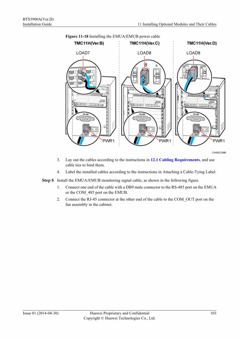
Figure 11-18 Installing the EMUA/EMUB power cable
3. Lay out the cables according to the instructions in 12.1 Cabling Requirements, and usecable ties to bind them.
4. Label the installed cables according to the instructions in Attaching a Cable-Tying Label.
Step 8 Install the EMUA/EMUB monitoring signal cable, as shown in the following figure.1. Connect one end of the cable with a DB9 male connector to the RS-485 port on the EMUA
or the COM_485 port on the EMUB.2. Connect the RJ-45 connector at the other end of the cable to the COM_OUT port on the
fan assembly in the cabinet.
BTS3900A(Ver.D)Installation Guide 11 Installing Optional Modules and Their Cables
Issue 01 (2014-04-30) Huawei Proprietary and ConfidentialCopyright © Huawei Technologies Co., Ltd.
103
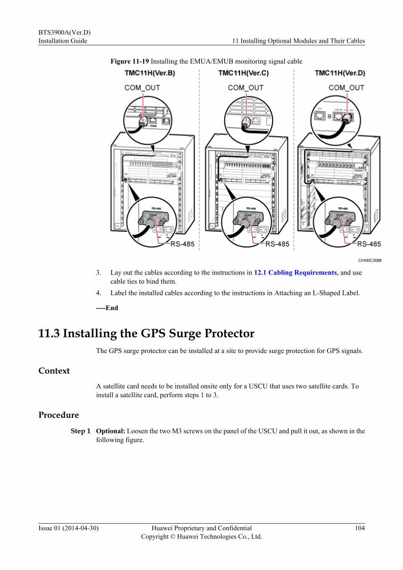
Figure 11-19 Installing the EMUA/EMUB monitoring signal cable
3. Lay out the cables according to the instructions in 12.1 Cabling Requirements, and usecable ties to bind them.
4. Label the installed cables according to the instructions in Attaching an L-Shaped Label.
----End
11.3 Installing the GPS Surge ProtectorThe GPS surge protector can be installed at a site to provide surge protection for GPS signals.
ContextA satellite card needs to be installed onsite only for a USCU that uses two satellite cards. Toinstall a satellite card, perform steps 1 to 3.
Procedure
Step 1 Optional: Loosen the two M3 screws on the panel of the USCU and pull it out, as shown in thefollowing figure.
BTS3900A(Ver.D)Installation Guide 11 Installing Optional Modules and Their Cables
Issue 01 (2014-04-30) Huawei Proprietary and ConfidentialCopyright © Huawei Technologies Co., Ltd.
104
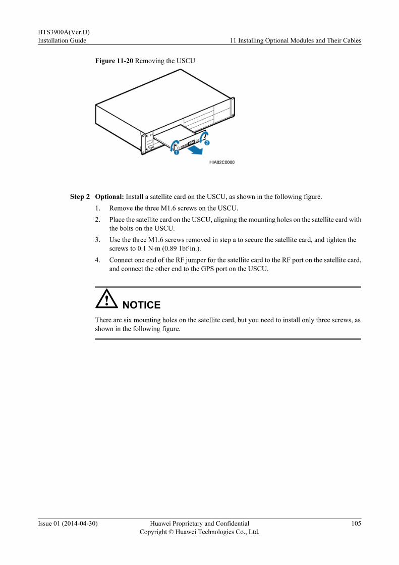
Figure 11-20 Removing the USCU
Step 2 Optional: Install a satellite card on the USCU, as shown in the following figure.1. Remove the three M1.6 screws on the USCU.2. Place the satellite card on the USCU, aligning the mounting holes on the satellite card with
the bolts on the USCU.3. Use the three M1.6 screws removed in step a to secure the satellite card, and tighten the
screws to 0.1 N·m (0.89 1bf·in.).4. Connect one end of the RF jumper for the satellite card to the RF port on the satellite card,
and connect the other end to the GPS port on the USCU.
NOTICEThere are six mounting holes on the satellite card, but you need to install only three screws, asshown in the following figure.
BTS3900A(Ver.D)Installation Guide 11 Installing Optional Modules and Their Cables
Issue 01 (2014-04-30) Huawei Proprietary and ConfidentialCopyright © Huawei Technologies Co., Ltd.
105

Figure 11-21 Installing a satellite card on the USCU
(1) Satellite card (2) RF jumper for the satellite card
Step 3 Optional: Install the USCU in the BBU, and tighten the captive screws on the USCU to 0.6 N·m(5.31 lbf·in.).
Step 4 Secure the GPS clock signal cable onto the support, and tighten the screws to 6.5 N·m (57.53lbf in.), as shown in the following figure.
BTS3900A(Ver.D)Installation Guide 11 Installing Optional Modules and Their Cables
Issue 01 (2014-04-30) Huawei Proprietary and ConfidentialCopyright © Huawei Technologies Co., Ltd.
106
Figure 11-22 Securing the GPS clock signal cable onto the support
(1) GPS clock signal cable (2) Support
Step 5 Secure the support onto the left inner wall of the cabinet, and tighten the screws to 1.2 N·m(10.62 lbf in.), as shown in the following figure.
Figure 11-23 Securing the support onto the cabinet
Step 6 Connect the GPS clock signal cable to the GPS port on the LMPT, USCU, or UMPTa6, as shownin the following figure.
NOTE
If the BBU is configured with an LMPT or UMPTa6, the GPS clock signal cable is preferentially connectedto the GPS port on the LMPT or UMPTa6.
BTS3900A(Ver.D)Installation Guide 11 Installing Optional Modules and Their Cables
Issue 01 (2014-04-30) Huawei Proprietary and ConfidentialCopyright © Huawei Technologies Co., Ltd.
107

Figure 11-24 Connecting the GPS clock signal cable to the USCU
(1) BBU (2) GPS support
Step 7 Use a torque wrench to secure the Protect port on the GPS surge protector onto the Type N50straight female connector at one end of the GPS signal cable, and tighten the screw to 4 N·m(35.40 lbf in.), as shown in the following figure.
Figure 11-25 Installing the GPS surge protector
(1) GPS surge protector
NOTE
The exterior of the GPS surge protector in this section is for reference only. The actual exterior may be different.
Step 8 Use a torque wrench to secure the GPS jumper to the Surge port on the GPS surge protector,and tighten the screw to 4 N·m (35.40 lbf in.), as shown in the following figure.
BTS3900A(Ver.D)Installation Guide 11 Installing Optional Modules and Their Cables
Issue 01 (2014-04-30) Huawei Proprietary and ConfidentialCopyright © Huawei Technologies Co., Ltd.
108

Figure 11-26 Installing the GPS jumper
Step 9 Lay out the cables according to the instructions in 12.1 Cabling Requirements, and use cableties to bind them.
Step 10 Label the installed cables according to the instructions in Attaching an L-Shaped Label.
----End
11.4 Installing the GATM and Bias-TeeIf the DRFU is installed at a site, the GATM and Bias-Tee must be installed at the site.
ContextA Bias-Tee couples the DC power or OOK signals into the feeder and a GATM is connected tothe antenna through the Bias-Tee. When a DRFU is configured, a GATM and a Bias-Tee mustbe installed, and usually a straight DIN Bias-Tee is used.
The following figure shows the ports on a straight DIN Bias-Tee and the following tabledescribes the cable connections on the straight DIN Bias-Tee.
Figure 11-27 Ports on a straight DIN Bias-Tee
BTS3900A(Ver.D)Installation Guide 11 Installing Optional Modules and Their Cables
Issue 01 (2014-04-30) Huawei Proprietary and ConfidentialCopyright © Huawei Technologies Co., Ltd.
109

Table 11-8 Cable connections on a straight DIN Bias-Tee
No. Cable Connected to Each Port
1 Feeder for the antenna system
2 Bias-Tee and RET control signal cable. The other end of the cable isconnected to any port from ANT0 to ANT5 on the GATM.
3 PGND cable
4 Jumper for the base station
The procedures for installing the GATM and Bias-Tee in the BTS3900A (Ver.B), BTS3900A(Ver.C), and BTS3900A (Ver.D) are the same. The following shows the procedure for installingthe GATM and Bias-Tee in the BTS3900A (Ver.D) cabinet.
The GATM must be installed closely below the BBU. If two GATM boards are needed, installthem next to each other below the BBU. The upper GATM is called GATM0, and the lowerGATM is called GATM1.
Procedure
Step 1 Install the GATM, as shown in the following figure.1. Slide the GATM into the installation position.2. Tighten the four M6 screws on the mounting ear on both sides of the GATM to 2 N·m (17.7
lbf·in.).
Figure 11-28 Installing the GATM
Step 2 Install the power cable for the GATM.
BTS3900A(Ver.D)Installation Guide 11 Installing Optional Modules and Their Cables
Issue 01 (2014-04-30) Huawei Proprietary and ConfidentialCopyright © Huawei Technologies Co., Ltd.
110
1. Connect the end with a 3V3 connector to the -48V port on the GATM and tighten the screwon the connector using a torque screwdriver to 0.6 N·m (0.44 ft·lb).
2. Add a connector to the other end of the cable according to the type of power equipmentand connect the end to the power equipment.
Base Station Cabinet Type PowerEquipment
InstallationPosition
Method ofAdding aConnector
BTS3900A(Ver.B)
APM30H(Ver.B)
DCDU-01 inthe RFC
l GATM0:SPARE1port
l GATM1:BBU port
Serial terminal,no need to beadded onsite.
TMC11H(Ver.B)
DCDU-03C inthe TMC11H
l GATM0:LOAD8port
l GATM1:LOAD7port
Add OTterminals. Fordetails, seeAssemblingthe OTTerminal andthe PowerCable.
BTS3900A(Ver.C)
APM30H(Ver.C)
l GATM0:DCDU-11A in theRFC
l GATM1:EPU03A-02/04 in theAPM30H
l GATM0:LOAD7port
l GATM1:BBU1 port
Add a tool-lessfemale(pressfit type)connector totwo core wiresaccording tothe instructionsin Assemblingthe Tool-LessFemaleConnector(Pressfit Type)and the PowerCable(2).
TMC11H(Ver.C)
DCDU-11C inthe TMC11H
l GATM0:LOAD8port
l GATM1:LOAD6port
BTS3900A(Ver.D)
APM30H(Ver.D)
l GATM0:DCDU-12A in theRFC
l GATM1:EPU05A-02/04 in theAPM30H
l GATM0:LOAD7port
l GATM1:LOAD5port
Add an EPC4connector. Fordetails, seeAssemblingthe EPC4Connector andthe PowerCable.
BTS3900A(Ver.D)Installation Guide 11 Installing Optional Modules and Their Cables
Issue 01 (2014-04-30) Huawei Proprietary and ConfidentialCopyright © Huawei Technologies Co., Ltd.
111

Base Station Cabinet Type PowerEquipment
InstallationPosition
Method ofAdding aConnector
TMC11H(Ver.D)
DCDU-12C inthe TMC11H
l GATM0:LOAD8port
l GATM1:LOAD7port
Step 3 Install the monitoring signal cable for the GATM.1. Connect one end of the cable to the COM1 port on the GATM.2. Connect the other end of the cable to the MON0 or MON1 port on the BBU.
Step 4 Install the monitoring signal cable between the CMUA/CMUE/CMUEA and the GATM.1. Connect one end of the cable to the COM2 port on the GATM.2. Connect the other end of the cable to the COM_IN port on the fan unit in the cabinet.
NOTE
The fan unit to be used in a cabinet varies according to the cabinet type. The fan unit types include: FAN01A, FAN 01B, FAN 01C, FAN 02A, FAN 02B, and FAN 02D.
Step 5 Route RF jumpers to the cabinet according to one of the routes shown in Figure 11-29.
Figure 11-29 Routing of RF jumpers
Step 6 Install the Bias-Tee, as shown in Figure 11-30.
BTS3900A(Ver.D)Installation Guide 11 Installing Optional Modules and Their Cables
Issue 01 (2014-04-30) Huawei Proprietary and ConfidentialCopyright © Huawei Technologies Co., Ltd.
112
Figure 11-30 Installing the Bias-Tee
(1) Bias-Tee (2) DIN female connector (3) RF jumper
NOTE
It is recommended that the lower Bias-Tee be installed first.
Step 7 Install the RET control signal cable, with one end connected to the DC/OOK port on the Bias-Tee and the other end to the ANT0 to ANT5 ports on the GATM, as shown in Figure 11-31 orFigure 11-32.
BTS3900A(Ver.D)Installation Guide 11 Installing Optional Modules and Their Cables
Issue 01 (2014-04-30) Huawei Proprietary and ConfidentialCopyright © Huawei Technologies Co., Ltd.
113

Figure 11-31 Installing the RET control signal cable (1)
Figure 11-32 Installing the RET control signal cable (2)
Step 8 Attach color codings to RF jumpers according to the instructions in Color Ring for the AntennaSystem and Attaching the Color Ring.
----End
BTS3900A(Ver.D)Installation Guide 11 Installing Optional Modules and Their Cables
Issue 01 (2014-04-30) Huawei Proprietary and ConfidentialCopyright © Huawei Technologies Co., Ltd.
114
11.5 Installing the DDFThe digital distribution frame (DDF) distributes alarm cables and E1/T1 cables.
Contextl The DDF is installed in the 1 U space reserved in the cabinet.l In the following figure showing the digital distribution module, a, b, and s have different
meanings.
– a and b indicate signal cables.
– s indicates a PGND cable.l Alarm cables are routed on the left side of the DDF, and E1/T1 cables are routed on the
right side of the DDF. All cables are routed from the top down.l The following procedure uses a twisted pair cable as an example. When installing an E1
coaxial cable, install an insulating pad between the wiring terminal and the DDF.
Procedure
Step 1 Distribute the twisted pair cable on the DDF on the BBU side. This twisted pair cable is connectedto the BBU.1. Insert the bare wires at one end of the twisted pair cable to the corresponding digital
distribution module according to the colors and labels of the wires.2. Use an impact tool to seat the wires of the twisted pair cable into the terminal blocks on
the DDF, as shown in Figure 11-33.
Step 2 Distribute the twisted pair cable on the DDF on the peer equipment side. This twisted pair cableis connected to the peer equipment.1. Insert the bare wires at one end of the twisted pair cable to the corresponding digital
distribution module according to the colors and labels of the wires.2. Use an impact tool to seat the wires of the twisted pair cable into the terminal blocks on
the DDF, as shown in Figure 11-33.
Step 3 Arrange the wires on the DDF, as shown in the following figure.
BTS3900A(Ver.D)Installation Guide 11 Installing Optional Modules and Their Cables
Issue 01 (2014-04-30) Huawei Proprietary and ConfidentialCopyright © Huawei Technologies Co., Ltd.
115

Figure 11-33 Cabling on the DDF
NOTE
l After distributing cables on the DDF, ensure that no bare wire is exposed outside the DDF.
l When interconnecting cables on both sides of the DDF, interconnect wires according to actualsituations. The colors of interconnected wires must be the same, as shown in Figure 11-33.
Step 4 Select the step according to the types of the cabinet.
If... Then...
An APM30H(Ver.B) or APM30H(Ver.C) is used Go toStep 5.
An APM30H(Ver.D) or BTS3900AL(Ver.A) is used Go toStep 6.
Step 5 Optional: If there is a filler module in the installation position, remove the filler module, asshown in the following figure.
BTS3900A(Ver.D)Installation Guide 11 Installing Optional Modules and Their Cables
Issue 01 (2014-04-30) Huawei Proprietary and ConfidentialCopyright © Huawei Technologies Co., Ltd.
116

1. Use a Phillips screwdriver to remove the two M6 screws from the mounting ear on eachside of the filler module.
2. Slide the filler module out of the cabinet.
NOTE
The removed filler modules must be installed in the vacant slots in the lower part of the cabinet from top down.If vacant slots are all occupied with filler modules, other redundant filler modules are discarded.
Figure 11-34 Removing the filler module
Step 6 Optional: If there is an air baffle in the installation position, remove the air baffle, as shown inthe following figure.
NOTE
The removed air baffles must be installed in the vacant slots in the lower part of the cabinet from top down. Ifvacant slots are all occupied with air baffles, other redundant air baffles are discarded.
Figure 11-35 Removing the air baffle
Step 7 Check whether floating nuts are installed on both sides of the 19-inch rack. If no, install thefloating nuts delivered with the DDF to both sides of the rack.
BTS3900A(Ver.D)Installation Guide 11 Installing Optional Modules and Their Cables
Issue 01 (2014-04-30) Huawei Proprietary and ConfidentialCopyright © Huawei Technologies Co., Ltd.
117

Step 8 Align the DDF with the cabinet, slide it into the cabinet, and use a screwdriver to tighten twoM6x12 screws on each side of the DDF to 2 N·m (17.70 lbf in.), as shown in the following figure.
Figure 11-36 Installing the DDF
----End
11.6 Installing the BatteriesThis section describes the procedure and precautions for installing the batteries and related cablesin the IBBS200D, IBBS200T, IBBS700D, and IBBS700T.
PrerequisitesA screwdriver and ESD gloves are available.
Context
DANGERl During the installation, avoid any contact between the exposed metal conductors in the power
cables and the metal housing of the cabinet.l During the installation, avoid short circuits or reverse connections between the positive and
negative poles of the batteries.l All tools used for installation must be insulated to avoid burning of batteries and to ensure
personal safety.
This section describes the procedure and precautions for installing batteries in an IBBS200D orIBBS200T. For the procedure for installing batteries in an IBBS700D/IBBS700T, see InstallingStorage Batteries in the IBBS700D or IBBS700T in IBBS700D&IBBS700T User Guide.
Procedure
Step 1 Check that the power input and output switches for the batteries are turned off to avoidovercurrent. The correct positions of the switches are shown by 1 and 2 in Figure 11-37.
BTS3900A(Ver.D)Installation Guide 11 Installing Optional Modules and Their Cables
Issue 01 (2014-04-30) Huawei Proprietary and ConfidentialCopyright © Huawei Technologies Co., Ltd.
118
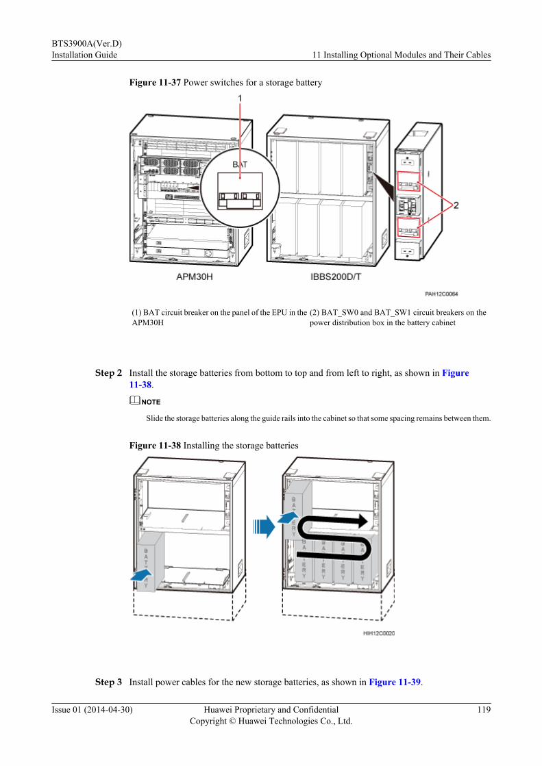
Figure 11-37 Power switches for a storage battery
(1) BAT circuit breaker on the panel of the EPU in theAPM30H
(2) BAT_SW0 and BAT_SW1 circuit breakers on thepower distribution box in the battery cabinet
Step 2 Install the storage batteries from bottom to top and from left to right, as shown in Figure11-38.
NOTE
Slide the storage batteries along the guide rails into the cabinet so that some spacing remains between them.
Figure 11-38 Installing the storage batteries
Step 3 Install power cables for the new storage batteries, as shown in Figure 11-39.
BTS3900A(Ver.D)Installation Guide 11 Installing Optional Modules and Their Cables
Issue 01 (2014-04-30) Huawei Proprietary and ConfidentialCopyright © Huawei Technologies Co., Ltd.
119

1. Remove terminal covers from the storage batteries.
2. Install copper bars between the poles of neighboring batteries for series connections.
3. First connect the negative power cable and then the positive power cable for each storagebattery. Negative power cables are black, and positive power cables are red.
Figure 11-39 Installing power cables for the storage batteries
The following figure shows the route of power cables in the battery cabinet.
Figure 11-40 Route of power cables for storage batteries
BTS3900A(Ver.D)Installation Guide 11 Installing Optional Modules and Their Cables
Issue 01 (2014-04-30) Huawei Proprietary and ConfidentialCopyright © Huawei Technologies Co., Ltd.
120
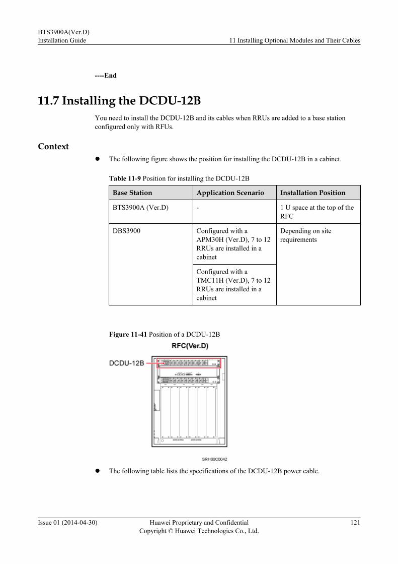
----End
11.7 Installing the DCDU-12BYou need to install the DCDU-12B and its cables when RRUs are added to a base stationconfigured only with RFUs.
Contextl The following figure shows the position for installing the DCDU-12B in a cabinet.
Table 11-9 Position for installing the DCDU-12B
Base Station Application Scenario Installation Position
BTS3900A (Ver.D) - 1 U space at the top of theRFC
DBS3900 Configured with aAPM30H (Ver.D), 7 to 12RRUs are installed in acabinet
Depending on siterequirements
Configured with aTMC11H (Ver.D), 7 to 12RRUs are installed in acabinet
Figure 11-41 Position of a DCDU-12B
l The following table lists the specifications of the DCDU-12B power cable.
BTS3900A(Ver.D)Installation Guide 11 Installing Optional Modules and Their Cables
Issue 01 (2014-04-30) Huawei Proprietary and ConfidentialCopyright © Huawei Technologies Co., Ltd.
121
Table 11-10 Cable specifications
BaseStation
ApplicationScenario
Cable Color Cross-Sectional Area
Connector
MostRegions
UK OneEnd
TheOtherEnd
BTS3900A(Ver.D)
AC RTN(+) Black Blue 25 mm2
or 0.039in.2, onegroup
OTterminal(M6)
OTterminal(M6)NEG(-) Blue Grey
BTS3900A(Ver.D)
DC RTN(+) Black Blue l 35mm2
or0.054 in.2
(lowsmokezerohalogen),onegroup
l 16mm2
or0.025 in.2,twogroups
OTterminal(M6)
Depending ontheexternalequipment
NEG(-) Blue Grey
DBS3900
Configured withaAPM30H(Ver.D),7 to 12RRUsareinstalledin acabinet
RTN(+) Black Blue 25 mm2
or 0.039in.2, onegroup
OTterminal(M6)
OTterminal(M6)NEG(-) Blue Grey
BTS3900A(Ver.D)Installation Guide 11 Installing Optional Modules and Their Cables
Issue 01 (2014-04-30) Huawei Proprietary and ConfidentialCopyright © Huawei Technologies Co., Ltd.
122
BaseStation
ApplicationScenario
Cable Color Cross-Sectional Area
Connector
MostRegions
UK OneEnd
TheOtherEnd
Configured withaTMC11H(Ver.D),7 to 12RRUsareinstalledin acabinet
RTN(+) Black Blue l 35mm2
or0.054 in.2
(lowsmokezerohalogen),onegroup
l 16mm2
or0.025 in.2,twogroups
OTterminal(M6)
Depending ontheexternalequipment
NEG(-) Blue Grey
Procedure
Step 1 Remove the four M6 screws on both sides of the slot for installing the DCDU-12B.
Step 2 Stick a cable claw onto the right side of the DCDU-12B, as shown in the following figure.
BTS3900A(Ver.D)Installation Guide 11 Installing Optional Modules and Their Cables
Issue 01 (2014-04-30) Huawei Proprietary and ConfidentialCopyright © Huawei Technologies Co., Ltd.
123

Figure 11-42 Installing a cable claw onto the right side of the DCDU-12B
(1) Double-sided tape
Step 3 Install the DCDU-12B, as shown in the following figure.1. Hold the DCDU-12B with both hands, and slide it into the cabinet until the mounting ears
on both sides of the DCDU-12B contact the columns.2. Tighten the four M6 screws on both sides of the DCDU-12B to 2 N·m (17.7 lbf·in.).
Figure 11-43 Installing the DCDU-12B
(1) DCDU-12B (2) Cable claw
Step 4 Prepare the DCDU-12B power cable.1. Cut the cable to the length suitable for the actual cable route.2. Add new connectors to both ends of the cable.
BTS3900A(Ver.D)Installation Guide 11 Installing Optional Modules and Their Cables
Issue 01 (2014-04-30) Huawei Proprietary and ConfidentialCopyright © Huawei Technologies Co., Ltd.
124
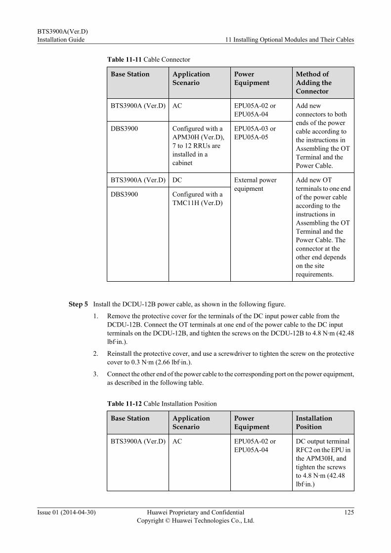
Table 11-11 Cable Connector
Base Station ApplicationScenario
PowerEquipment
Method ofAdding theConnector
BTS3900A (Ver.D) AC EPU05A-02 orEPU05A-04
Add newconnectors to bothends of the powercable according tothe instructions inAssembling the OTTerminal and thePower Cable.
DBS3900 Configured with aAPM30H (Ver.D),7 to 12 RRUs areinstalled in acabinet
EPU05A-03 orEPU05A-05
BTS3900A (Ver.D) DC External powerequipment
Add new OTterminals to one endof the power cableaccording to theinstructions inAssembling the OTTerminal and thePower Cable. Theconnector at theother end dependson the siterequirements.
DBS3900 Configured with aTMC11H (Ver.D)
Step 5 Install the DCDU-12B power cable, as shown in the following figure.
1. Remove the protective cover for the terminals of the DC input power cable from theDCDU-12B. Connect the OT terminals at one end of the power cable to the DC inputterminals on the DCDU-12B, and tighten the screws on the DCDU-12B to 4.8 N·m (42.48lbf·in.).
2. Reinstall the protective cover, and use a screwdriver to tighten the screw on the protectivecover to 0.3 N·m (2.66 lbf·in.).
3. Connect the other end of the power cable to the corresponding port on the power equipment,as described in the following table.
Table 11-12 Cable Installation Position
Base Station ApplicationScenario
PowerEquipment
InstallationPosition
BTS3900A (Ver.D) AC EPU05A-02 orEPU05A-04
DC output terminalRFC2 on the EPU inthe APM30H, andtighten the screwsto 4.8 N·m (42.48lbf·in.)
BTS3900A(Ver.D)Installation Guide 11 Installing Optional Modules and Their Cables
Issue 01 (2014-04-30) Huawei Proprietary and ConfidentialCopyright © Huawei Technologies Co., Ltd.
125
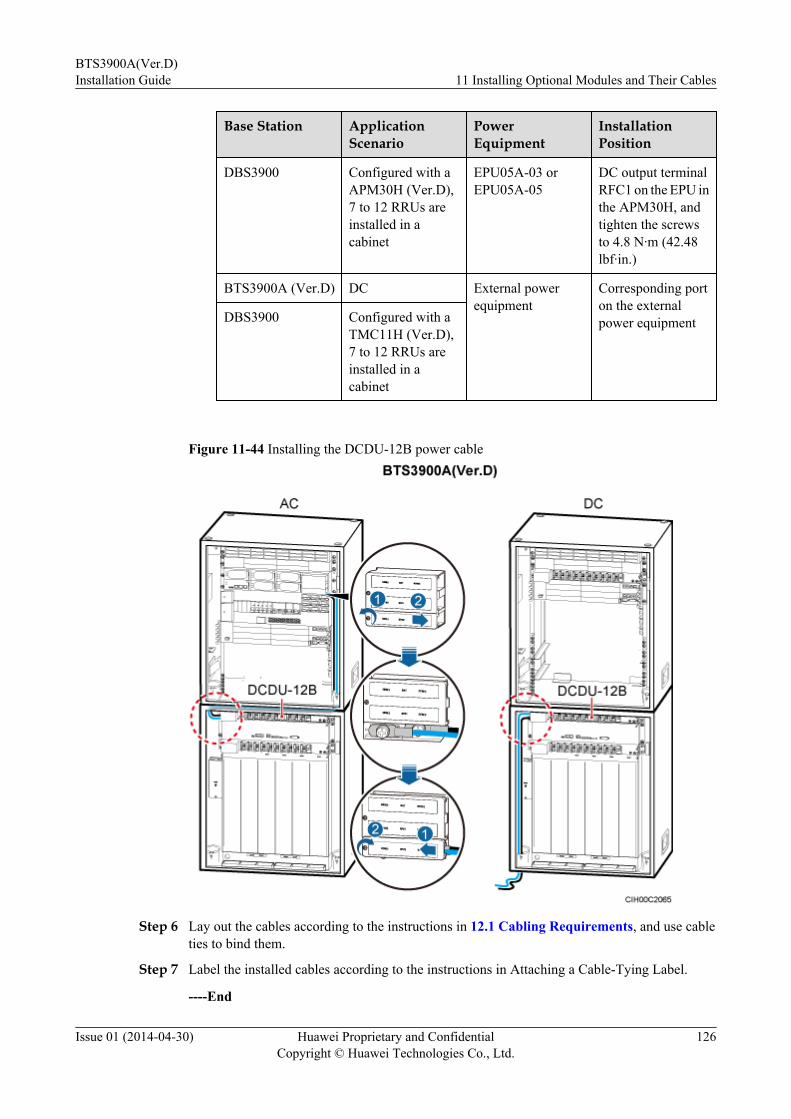
Base Station ApplicationScenario
PowerEquipment
InstallationPosition
DBS3900 Configured with aAPM30H (Ver.D),7 to 12 RRUs areinstalled in acabinet
EPU05A-03 orEPU05A-05
DC output terminalRFC1 on the EPU inthe APM30H, andtighten the screwsto 4.8 N·m (42.48lbf·in.)
BTS3900A (Ver.D) DC External powerequipment
Corresponding porton the externalpower equipmentDBS3900 Configured with a
TMC11H (Ver.D),7 to 12 RRUs areinstalled in acabinet
Figure 11-44 Installing the DCDU-12B power cable
Step 6 Lay out the cables according to the instructions in 12.1 Cabling Requirements, and use cableties to bind them.
Step 7 Label the installed cables according to the instructions in Attaching a Cable-Tying Label.
----End
BTS3900A(Ver.D)Installation Guide 11 Installing Optional Modules and Their Cables
Issue 01 (2014-04-30) Huawei Proprietary and ConfidentialCopyright © Huawei Technologies Co., Ltd.
126
11.8 Installing the BBUWhen a site is configured with RFUs and RRUs, you need to install a second BBU and its cables.
ContextThe following table and figure show the installation positions of the BBU in the BTS3900A.
Table 11-13 Installation position of the BBU
Base Station Type Installation Position
BTS3900A (Ver.B) and BTS3900A (Ver.C) The second BBU is installed in the secondAPM30H or TMC11H, and the installationposition is the same as the first BBU, asshown in Figure 11-45.
BTS3900A (Ver.D) The second BBU is installed in the 2 U spacebelow the first BBU in the basic cabinet. Ifthere is no available space in the basiccabinet, the second BBU is installed in theextension cabinet, and the installationposition is the same as the first BBU, asshown in Figure 11-46.
BTS3900A(Ver.D)Installation Guide 11 Installing Optional Modules and Their Cables
Issue 01 (2014-04-30) Huawei Proprietary and ConfidentialCopyright © Huawei Technologies Co., Ltd.
127

Figure 11-45 BBU installed in the BTS3900A (Ver.B) or BTS3900A (Ver.C)
(1) The BBU is installed in the APM30H. (2) The BBU is installed in the TMC11H.
BTS3900A(Ver.D)Installation Guide 11 Installing Optional Modules and Their Cables
Issue 01 (2014-04-30) Huawei Proprietary and ConfidentialCopyright © Huawei Technologies Co., Ltd.
128

Figure 11-46 BBU installed in the BTS3900A (Ver.D)
(1) Both BBUs are installed in one APM30H. (2) Two BBUs are separately installed in the two APM30Hs.
(3) Both BBUs are installed in one TMC11H. (4) Two BBUs are separately installed in the two TMC11Hs.
Procedure
Step 1 Select the step according to the types of the APM30H.
If... Then...
An APM30H(Ver.B), APM30H(Ver.C), TMC11H(Ver.B), or TMC11H(Ver.C) is used
Go toStep 2.
An APM30H(Ver.D) or TMC11H(Ver.D) is used Go toStep 3.
Step 2 Optional: If there is a filler module in the installation position, remove the filler module, asshown in the following figure.
1. Use a Phillips screwdriver to remove the two M6 screws from the mounting ear on eachside of the filler module.
2. Slide the filler module out of the cabinet.
NOTE
The removed filler modules must be installed in the vacant slots in the lower part of the cabinet from top down.If vacant slots are all occupied with filler modules, other redundant filler modules are discarded.
BTS3900A(Ver.D)Installation Guide 11 Installing Optional Modules and Their Cables
Issue 01 (2014-04-30) Huawei Proprietary and ConfidentialCopyright © Huawei Technologies Co., Ltd.
129
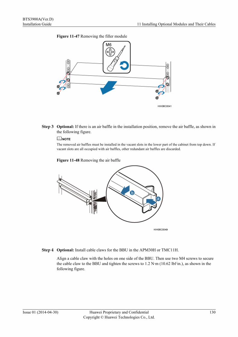
Figure 11-47 Removing the filler module
Step 3 Optional: If there is an air baffle in the installation position, remove the air baffle, as shown inthe following figure.
NOTE
The removed air baffles must be installed in the vacant slots in the lower part of the cabinet from top down. Ifvacant slots are all occupied with air baffles, other redundant air baffles are discarded.
Figure 11-48 Removing the air baffle
Step 4 Optional: Install cable claws for the BBU in the APM30H or TMC11H.
Align a cable claw with the holes on one side of the BBU. Then use two M4 screws to securethe cable claw to the BBU and tighten the screws to 1.2 N·m (10.62 lbf·in.), as shown in thefollowing figure.
BTS3900A(Ver.D)Installation Guide 11 Installing Optional Modules and Their Cables
Issue 01 (2014-04-30) Huawei Proprietary and ConfidentialCopyright © Huawei Technologies Co., Ltd.
130
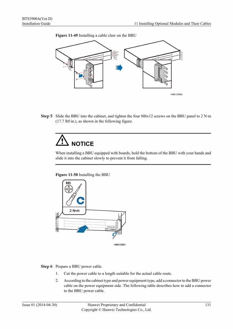
Figure 11-49 Installing a cable claw on the BBU
Step 5 Slide the BBU into the cabinet, and tighten the four M6x12 screws on the BBU panel to 2 N·m(17.7 lbf·in.), as shown in the following figure.
NOTICEWhen installing a BBU equipped with boards, hold the bottom of the BBU with your hands andslide it into the cabinet slowly to prevent it from falling.
Figure 11-50 Installing the BBU
Step 6 Prepare a BBU power cable.
1. Cut the power cable to a length suitable for the actual cable route.
2. According to the cabinet type and power equipment type, add a connector to the BBU powercable on the power equipment side. The following table describes how to add a connectorto the BBU power cable.
BTS3900A(Ver.D)Installation Guide 11 Installing Optional Modules and Their Cables
Issue 01 (2014-04-30) Huawei Proprietary and ConfidentialCopyright © Huawei Technologies Co., Ltd.
131
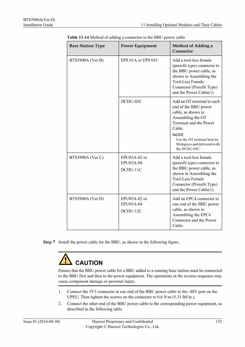
Table 11-14 Method of adding a connector to the BBU power cable
Base Station Type Power Equipment Method of Adding aConnector
BTS3900A (Ver.B) EPS 01A or EPS 01C Add a tool-less female(pressfit type) connector tothe BBU power cable, asshown in Assembling theTool-Less FemaleConnector (Pressfit Type)and the Power Cable(1).
DCDU-03C Add an OT terminal to eachend of the BBU powercable, as shown inAssembling the OTTerminal and the PowerCable.NOTE
Use the OT terminal bent by90 degrees and delivered withthe DCDU-03C.
BTS3900A (Ver.C) EPU03A-02 orEPU03A-04DCDU-11C
Add a tool-less female(pressfit type) connector tothe BBU power cable, asshown in Assembling theTool-Less FemaleConnector (Pressfit Type)and the Power Cable(1).
BTS3900A (Ver.D) EPU05A-02 orEPU05A-04DCDU-12C
Add an EPC4 connector toone end of the BBU powercable, as shown inAssembling the EPC4Connector and the PowerCable.
Step 7 Install the power cable for the BBU, as shown in the following figure.
CAUTIONEnsure that the BBU power cable for a BBU added to a running base station must be connectedto the BBU first and then to the power equipment. The operations in the reverse sequence maycause component damage or personal injury.
1. Connect the 3V3 connector at one end of the BBU power cable to the -48V port on theUPEU. Then tighten the screws on the connector to 0.6 N·m (5.31 lbf·in.).
2. Connect the other end of the BBU power cable to the corresponding power equipment, asdescribed in the following table.
BTS3900A(Ver.D)Installation Guide 11 Installing Optional Modules and Their Cables
Issue 01 (2014-04-30) Huawei Proprietary and ConfidentialCopyright © Huawei Technologies Co., Ltd.
132

Table 11-15 Installation position of BBU power cable
Base StationType
Cabinet PowerEquipment
InstallationPosition
BTS3900A (Ver.B) APM30H (Ver.B) EPS 01A or EPS01C
LOAD1 or LOAD2
TMC11H (Ver.B) DCDU-03C LOAD6
BTS3900A (Ver.C) APM30H (Ver.C) EPU03A-02 orEPU03A-04
BBU_0 or BBU_1
TMC11H (Ver.C) DCDU-11C LOAD6 or LOAD7
BTS3900A (Ver.D) APM30H (Ver.D) EPU05A-02 orEPU05A-04
LOAD0 or LOAD1
TMC11H (Ver.D) DCDU-12C LOAD6 or LOAD7
BTS3900A(Ver.D)Installation Guide 11 Installing Optional Modules and Their Cables
Issue 01 (2014-04-30) Huawei Proprietary and ConfidentialCopyright © Huawei Technologies Co., Ltd.
133
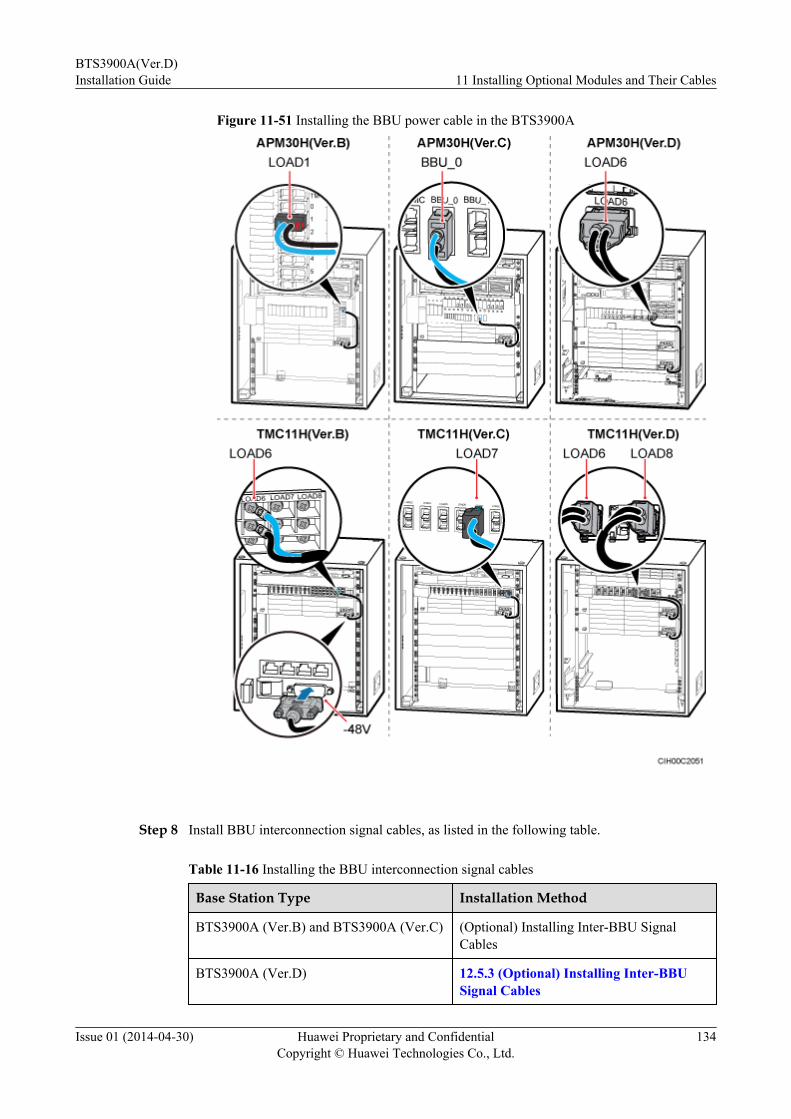
Figure 11-51 Installing the BBU power cable in the BTS3900A
Step 8 Install BBU interconnection signal cables, as listed in the following table.
Table 11-16 Installing the BBU interconnection signal cables
Base Station Type Installation Method
BTS3900A (Ver.B) and BTS3900A (Ver.C) (Optional) Installing Inter-BBU SignalCables
BTS3900A (Ver.D) 12.5.3 (Optional) Installing Inter-BBUSignal Cables
BTS3900A(Ver.D)Installation Guide 11 Installing Optional Modules and Their Cables
Issue 01 (2014-04-30) Huawei Proprietary and ConfidentialCopyright © Huawei Technologies Co., Ltd.
134

Step 9 Lay out the cables according to the instructions in 12.1 Cabling Requirements, and use cableties to bind them.
Step 10 Label the installed cables according to the instructions in Attaching a Cable-Tying Label.
----End
11.9 Installing Boards in the BBU and surge protectionboards
When an outdoor base station originally configured with RFUs is expanded to support RFUsand RRUs, BBU boards and surge protection boards need to be installed onsite. When an indoorbase station originally configured with RFUs is expanded to support RFUs and RRUs, only BBUboards need to be installed onsite.
Contextl The boards in the BBU to be installed onsite include the WMPT, WBBP, GTMU, GBBP,
LMPT, LBBP, UTRP, UPEU, and UEIU. The actual boards to be installed depend on theconfiguration requirements of a base station. The following uses the procedure for installingthe WMPT and UPEU as an example. The procedures for installing other preceding boardsare the same.
l The surge protection boards to be installed include the UELP and UFLP.
Operation Rulesl When moving a board, you must hold the board with both hands, as shown in the following
figure.
Figure 11-52 Incorrect and correct operations when moving a board
l When installing a board, you must hold the ejector lever side of the board with one hand
and hold another side of the board with the other hand to ensure that the board is movingin the correct direction. Do not hold the board with only one hand and never apply lateralforces to the board. The following figure shows incorrect and correct operations wheninstalling a board.
BTS3900A(Ver.D)Installation Guide 11 Installing Optional Modules and Their Cables
Issue 01 (2014-04-30) Huawei Proprietary and ConfidentialCopyright © Huawei Technologies Co., Ltd.
135
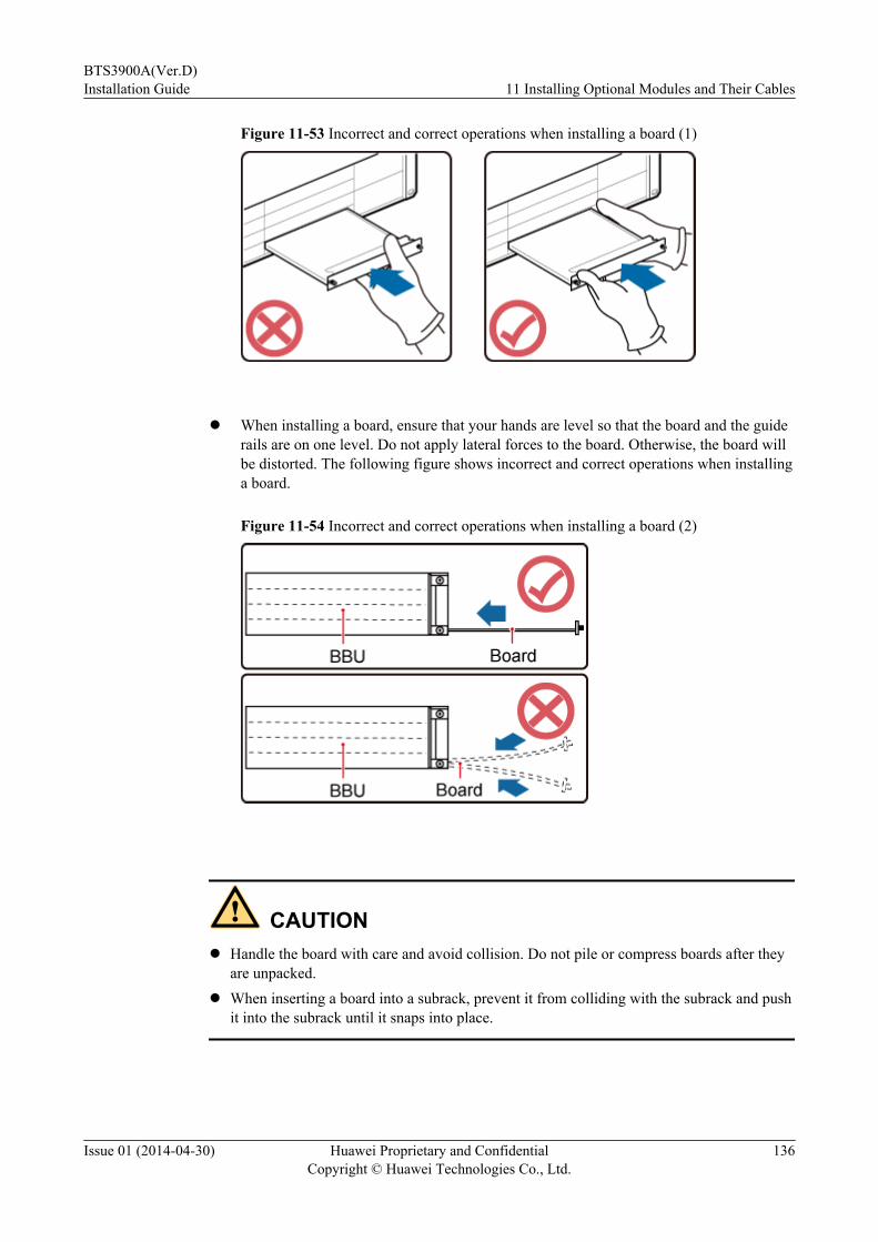
Figure 11-53 Incorrect and correct operations when installing a board (1)
l When installing a board, ensure that your hands are level so that the board and the guide
rails are on one level. Do not apply lateral forces to the board. Otherwise, the board willbe distorted. The following figure shows incorrect and correct operations when installinga board.
Figure 11-54 Incorrect and correct operations when installing a board (2)
CAUTIONl Handle the board with care and avoid collision. Do not pile or compress boards after they
are unpacked.l When inserting a board into a subrack, prevent it from colliding with the subrack and push
it into the subrack until it snaps into place.
BTS3900A(Ver.D)Installation Guide 11 Installing Optional Modules and Their Cables
Issue 01 (2014-04-30) Huawei Proprietary and ConfidentialCopyright © Huawei Technologies Co., Ltd.
136

Procedure
Step 1 Put on an ESD wrist strap or a pair of ESD gloves.
NOTICETake proper ESD protection measures, for example, put on an ESD wrist strap or a pair of ESDgloves, to prevent electrostatic damage to the boards, modules, or other electronic components.
Step 2 Install the WMPT and UPEU.
1. Remove the screws on the filler panels in the slots to be used, and gently remove the fillerpanels.
2. If there are ejector levers on the panels of the boards, raise them and remove the boards. Ifthere are no ejector levers, directly remove the boards.
3. Slowly insert the board into the slot until it snaps into place. Then, lower the ejector levers.
4. Tighten the captive screws on the panel to 0.6 N·m (5.31 lbf·in.).
Figure 11-55 Installing boards in the BBU
Step 3 Optional: In an outdoor base station, you need to install a UELP or UFLP. The followingdescribes how to install a UELP in an SLPU as an example. The procedure for installing a UELPor UFLP in the surge protection subrack for transmission signals in a BTS3900AL (Ver.A) issimilar.
1. Remove the screws on the filler panels in the slots to be used, and gently remove the fillerpanels.
2. Slowly insert the board into the slot until it snaps into place.
3. Tighten the captive screws on the panel to 0.6 N·m (5.31 lbf·in.).
BTS3900A(Ver.D)Installation Guide 11 Installing Optional Modules and Their Cables
Issue 01 (2014-04-30) Huawei Proprietary and ConfidentialCopyright © Huawei Technologies Co., Ltd.
137
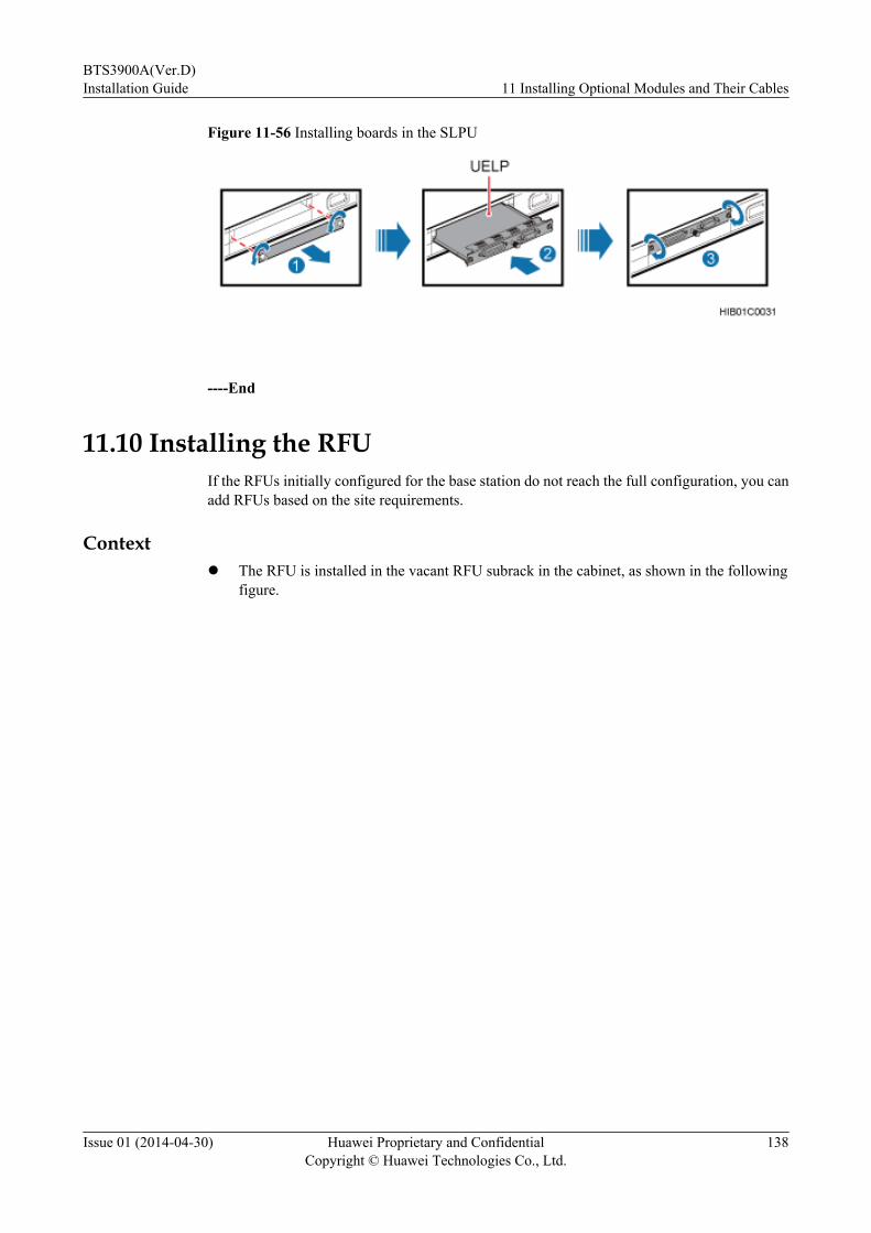
Figure 11-56 Installing boards in the SLPU
----End
11.10 Installing the RFUIf the RFUs initially configured for the base station do not reach the full configuration, you canadd RFUs based on the site requirements.
Contextl The RFU is installed in the vacant RFU subrack in the cabinet, as shown in the following
figure.
BTS3900A(Ver.D)Installation Guide 11 Installing Optional Modules and Their Cables
Issue 01 (2014-04-30) Huawei Proprietary and ConfidentialCopyright © Huawei Technologies Co., Ltd.
138
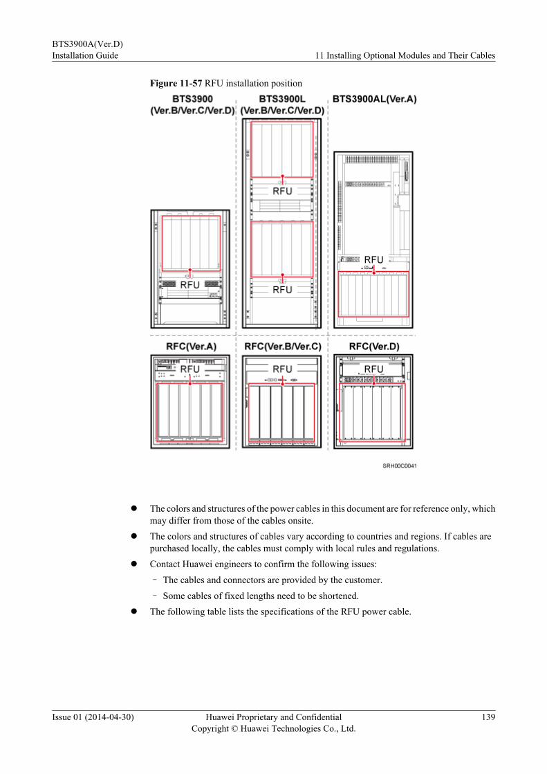
Figure 11-57 RFU installation position
l The colors and structures of the power cables in this document are for reference only, which
may differ from those of the cables onsite.l The colors and structures of cables vary according to countries and regions. If cables are
purchased locally, the cables must comply with local rules and regulations.l Contact Huawei engineers to confirm the following issues:
– The cables and connectors are provided by the customer.
– Some cables of fixed lengths need to be shortened.l The following table lists the specifications of the RFU power cable.
BTS3900A(Ver.D)Installation Guide 11 Installing Optional Modules and Their Cables
Issue 01 (2014-04-30) Huawei Proprietary and ConfidentialCopyright © Huawei Technologies Co., Ltd.
139
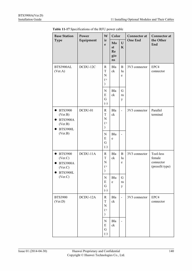
Table 11-17 Specifications of the RFU power cable
Base StationType
PowerEquipment
Wire
Color Connector atOne End
Connector atthe OtherEndMo
stRegions
UK
BTS3900AL(Ver.A)
DCDU-12C RTN(+)
Black
Blue
3V3 connector EPC4connector
NEG(-)
Black
Gray
l BTS3900(Ver.B)
l BTS3900A(Ver.B)
l BTS3900L(Ver.B)
DCDU-01 RTN(+)
Black
- 3V3 connector Parallelterminal
NEG(-)
Blue
-
l BTS3900(Ver.C)
l BTS3900A(Ver.C)
l BTS3900L(Ver.C)
DCDU-11A RTN(+)
Black
Blue
3V3 connector Tool-lessfemaleconnector(pressfit type)
NEG(-)
Blue
Gray
BTS3900(Ver.D)
DCDU-12A RTN(+)
Black
- 3V3 connector EPC4connector
NEG(-)
Black
-
BTS3900A(Ver.D)Installation Guide 11 Installing Optional Modules and Their Cables
Issue 01 (2014-04-30) Huawei Proprietary and ConfidentialCopyright © Huawei Technologies Co., Ltd.
140
Base StationType
PowerEquipment
Wire
Color Connector atOne End
Connector atthe OtherEndMo
stRegions
UK
l BTS3900A(Ver.D)
l BTS3900L(Ver.D)
DCDU-12A RTN(+)
Black
Blue
3V3 connector EPC4connector
NEG(-)
Black
Gray
Procedure
Step 1 Put on an ESD wrist strap or a pair of ESD gloves.
NOTICETake proper ESD protection measures, for example, put on an ESD wrist strap or a pair of ESDgloves, to prevent electrostatic damage to the boards, modules, or other electronic components.
Step 2 Remove the 3V3 connector from the lower part of the filler panel in the slot where the RFU isto be installed.
Step 3 Remove the filler panel.l If the base station uses the Ver.D cabinets, turn the knob on the upper part of the filler panel
in the direction indicated, lift the filler panel slightly, and then pull out the filler panel, asshown in the following figure.
BTS3900A(Ver.D)Installation Guide 11 Installing Optional Modules and Their Cables
Issue 01 (2014-04-30) Huawei Proprietary and ConfidentialCopyright © Huawei Technologies Co., Ltd.
141
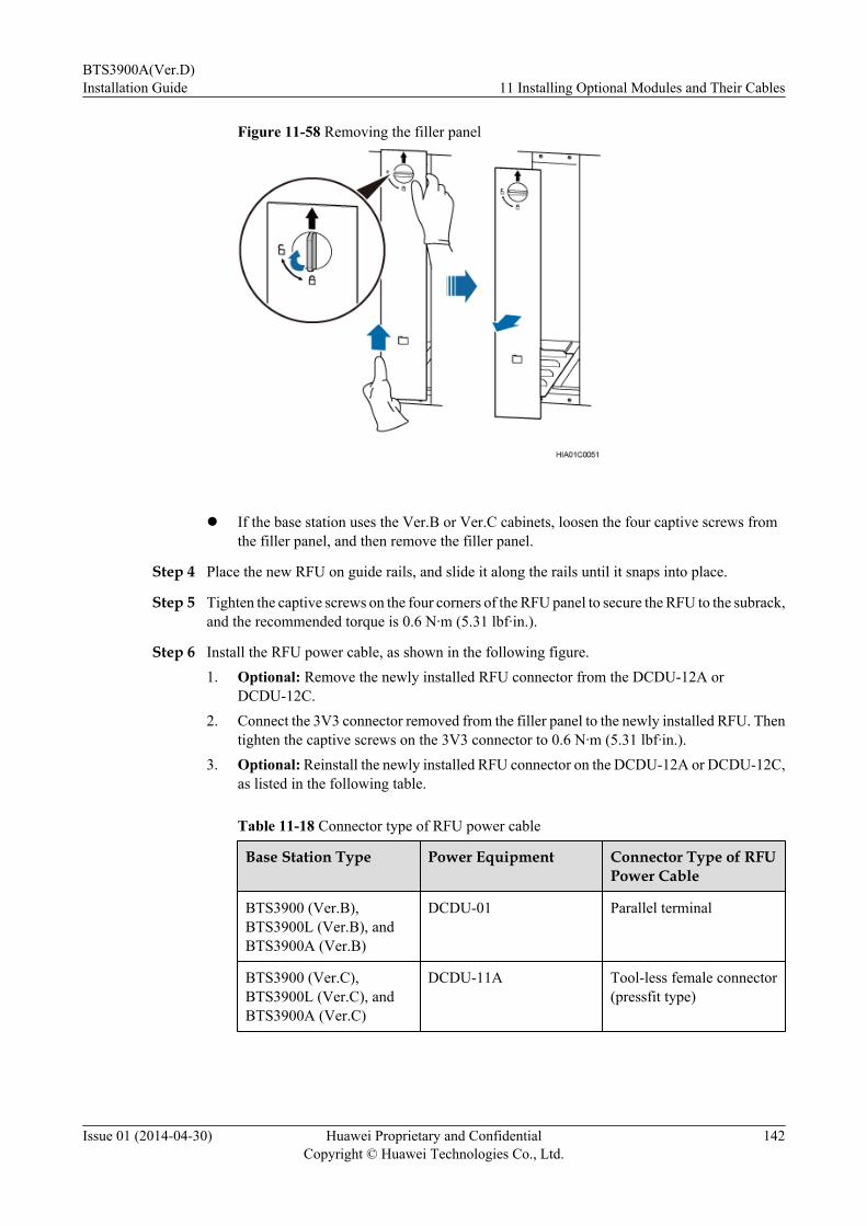
Figure 11-58 Removing the filler panel
l If the base station uses the Ver.B or Ver.C cabinets, loosen the four captive screws from
the filler panel, and then remove the filler panel.
Step 4 Place the new RFU on guide rails, and slide it along the rails until it snaps into place.
Step 5 Tighten the captive screws on the four corners of the RFU panel to secure the RFU to the subrack,and the recommended torque is 0.6 N·m (5.31 lbf·in.).
Step 6 Install the RFU power cable, as shown in the following figure.1. Optional: Remove the newly installed RFU connector from the DCDU-12A or
DCDU-12C.2. Connect the 3V3 connector removed from the filler panel to the newly installed RFU. Then
tighten the captive screws on the 3V3 connector to 0.6 N·m (5.31 lbf·in.).3. Optional: Reinstall the newly installed RFU connector on the DCDU-12A or DCDU-12C,
as listed in the following table.
Table 11-18 Connector type of RFU power cable
Base Station Type Power Equipment Connector Type of RFUPower Cable
BTS3900 (Ver.B),BTS3900L (Ver.B), andBTS3900A (Ver.B)
DCDU-01 Parallel terminal
BTS3900 (Ver.C),BTS3900L (Ver.C), andBTS3900A (Ver.C)
DCDU-11A Tool-less female connector(pressfit type)
BTS3900A(Ver.D)Installation Guide 11 Installing Optional Modules and Their Cables
Issue 01 (2014-04-30) Huawei Proprietary and ConfidentialCopyright © Huawei Technologies Co., Ltd.
142

Base Station Type Power Equipment Connector Type of RFUPower Cable
BTS3900 (Ver.D),BTS3900L (Ver.D), andBTS3900A (Ver.D)
DCDU-12A EPC4 connector
BTS3900AL (Ver.A) DCDU-12C EPC4 connector
CAUTIONEnsure that the RFU power cable for an RFU added to a running base station must beconnected to the RFU first and then to the power equipment. The operations in the reversesequence may cause component damage or personal injury.
Figure 11-59 Installing the RFU power cable
Step 7 Install the RF jumpers, as described in the following table.
Table 11-19 Installing RF jumpers
Base Station Type Installation Method
BTS3900A (Ver.B), BTS3900A (Ver.C), andBTS3900A (Ver.D)
12.6 Installing RF Jumpers
BTS3900 (Ver.B), BTS3900 (Ver.C), andBTS3900 (Ver.D)
Installing RF Jumpers
BTS3900A(Ver.D)Installation Guide 11 Installing Optional Modules and Their Cables
Issue 01 (2014-04-30) Huawei Proprietary and ConfidentialCopyright © Huawei Technologies Co., Ltd.
143

Base Station Type Installation Method
BTS3900L (Ver.B), BTS3900L (Ver.C), andBTS3900L (Ver.D)
Installing RF Jumpers
BTS3900AL(Ver.A) Installing RF Jumpers
Step 8 Install the CPRI electrical cables, as described in the following table.
Table 11-20 Installing CPRI electrical cables
Base Station Type Installation Method
BTS3900A (Ver.B), BTS3900A (Ver.C), andBTS3900A (Ver.D)
12.7 (Optional) Installing the CPRIElectrical Cables
BTS3900 (Ver.B), BTS3900 (Ver.C), andBTS3900 (Ver.D)
(Optional) Installing CPRI Electrical Cables
BTS3900L (Ver.B), BTS3900L (Ver.C), andBTS3900L (Ver.D)
(Optional) Installing CPRI Electrical Cables
BTS3900AL(Ver.A) (Optional) Installing CPRI Electrical Cables
Step 9 Lay out the cables according to the instructions in 12.1 Cabling Requirements, and use cableties to bind them.
Step 10 Optional: In an outdoor base station, use a PVC corrugated pipe to protect the cables outsidethe cabinet, and tie the pipe to the cable hole on the cabinet.
Step 11 Label the installed cables according to the instructions in Attaching a Sign Plate Label.
----End
11.11 Installing the RRUIf a site is configured with RFUs and RRUs, the RRUs and their cables must be installed onsite.For details, see the related RRU installation guide.
11.12 Installing the AC HeaterWhen the environmental temperature of a cabinet is low, the cabinet can be configured with aheater so that the temperature in the cabinet is kept in a proper range. This section describes theprocedure for installing a heater in an APM30H or TMC11H.
ContextThe procedure for installing an AC heater is the same for the APM30H (Ver.B), APM30H(Ver.C), and APM30H (Ver.D). The procedure for installing an AC heater is the same for theTMC11H (Ver.B), TMC11H (Ver.C), and TMC11H (Ver.D). The figures in this section use theAPM30H (Ver.D) and TMC11H (Ver.D) as examples.
BTS3900A(Ver.D)Installation Guide 11 Installing Optional Modules and Their Cables
Issue 01 (2014-04-30) Huawei Proprietary and ConfidentialCopyright © Huawei Technologies Co., Ltd.
144
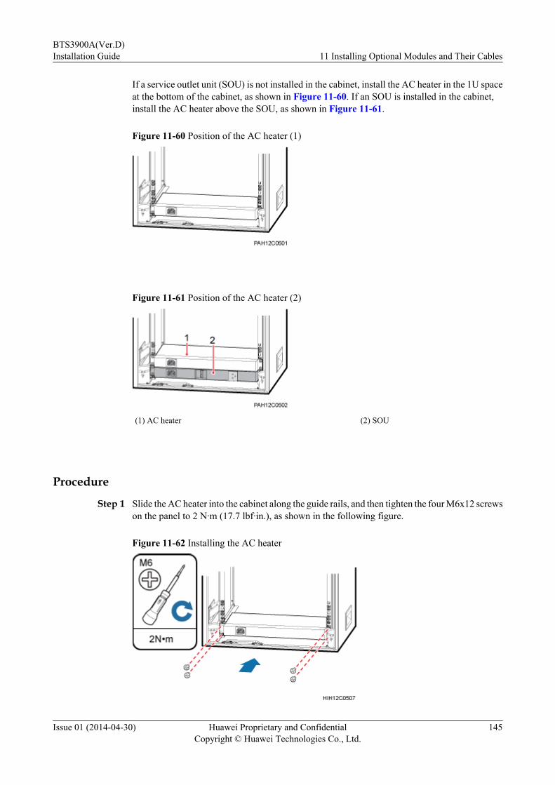
If a service outlet unit (SOU) is not installed in the cabinet, install the AC heater in the 1U spaceat the bottom of the cabinet, as shown in Figure 11-60. If an SOU is installed in the cabinet,install the AC heater above the SOU, as shown in Figure 11-61.
Figure 11-60 Position of the AC heater (1)
Figure 11-61 Position of the AC heater (2)
(1) AC heater (2) SOU
Procedure
Step 1 Slide the AC heater into the cabinet along the guide rails, and then tighten the four M6x12 screwson the panel to 2 N·m (17.7 lbf·in.), as shown in the following figure.
Figure 11-62 Installing the AC heater
BTS3900A(Ver.D)Installation Guide 11 Installing Optional Modules and Their Cables
Issue 01 (2014-04-30) Huawei Proprietary and ConfidentialCopyright © Huawei Technologies Co., Ltd.
145

Step 2 Install the AC heater power cable.
If... Then...
The AC heater is installed in an APM30H Perform Step 2.1
The AC heater is installed in a TMC11H Perform Step 2.2
1. Install the AC heater power cable in the APM30H.
a. Remove the cover plate of the AC junction box.
b. Connect the C13 connector at the other end of the AC heater power cable to the powerinput port on the AC heater.
c. Connect the OT terminals at one end of the brown, blue, and green and yellow wiresof the AC heater power cable to the L0, N0, and PE terminals in the AC junction box,respectively.
d. Install the cover plate of the AC junction box and tighten the screws on the cover plateto 0.3 N·m (2.66 lbf·in.).
Figure 11-63 Installing the AC heater power cable
2. Install the AC heater power cable in the TMC11H, as shown in Figure 11-64 and Figure11-65.
a. Remove the cover plate of the AC junction box.
b. Connect the C13 connector at the other end of the AC heater power cable to the powerinput port on the AC heater.
BTS3900A(Ver.D)Installation Guide 11 Installing Optional Modules and Their Cables
Issue 01 (2014-04-30) Huawei Proprietary and ConfidentialCopyright © Huawei Technologies Co., Ltd.
146
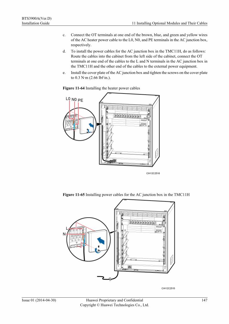
c. Connect the OT terminals at one end of the brown, blue, and green and yellow wiresof the AC heater power cable to the L0, N0, and PE terminals in the AC junction box,respectively.
d. To install the power cables for the AC junction box in the TMC11H, do as follows:Route the cables into the cabinet from the left side of the cabinet, connect the OTterminals at one end of the cables to the L and N terminals in the AC junction box inthe TMC11H and the other end of the cables to the external power equipment.
e. Install the cover plate of the AC junction box and tighten the screws on the cover plateto 0.3 N·m (2.66 lbf·in.).
Figure 11-64 Installing the heater power cables
Figure 11-65 Installing power cables for the AC junction box in the TMC11H
BTS3900A(Ver.D)Installation Guide 11 Installing Optional Modules and Their Cables
Issue 01 (2014-04-30) Huawei Proprietary and ConfidentialCopyright © Huawei Technologies Co., Ltd.
147
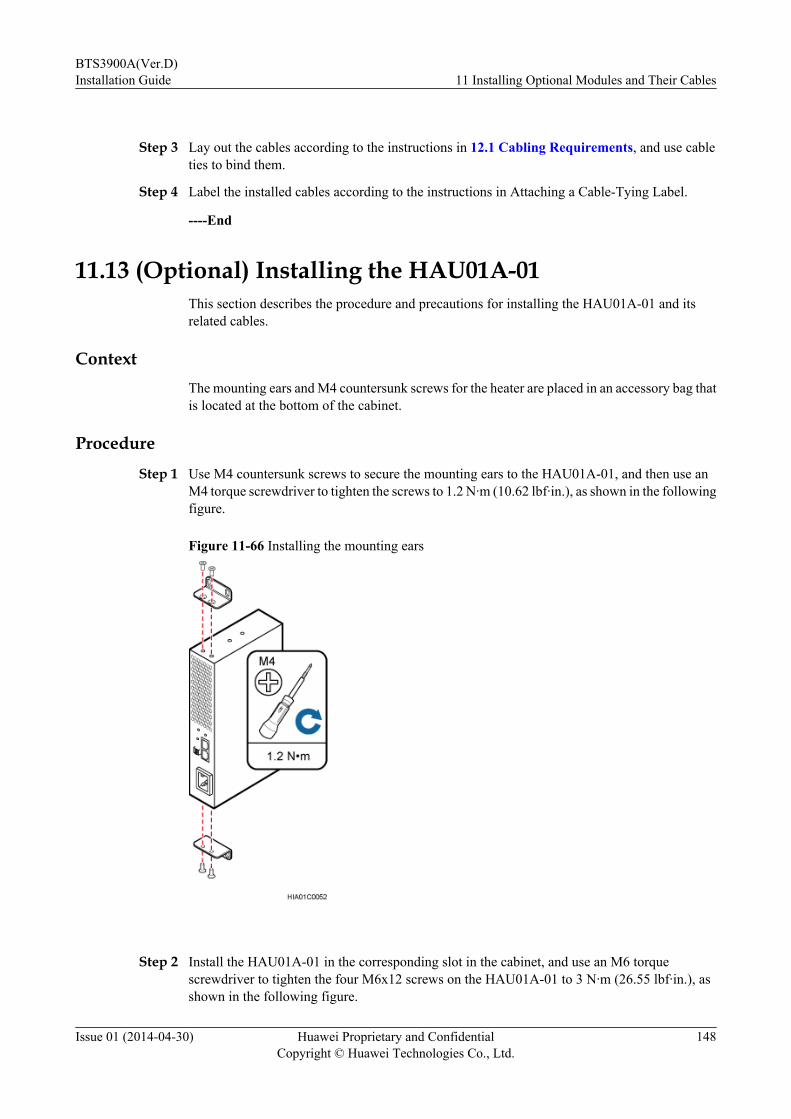
Step 3 Lay out the cables according to the instructions in 12.1 Cabling Requirements, and use cableties to bind them.
Step 4 Label the installed cables according to the instructions in Attaching a Cable-Tying Label.
----End
11.13 (Optional) Installing the HAU01A-01This section describes the procedure and precautions for installing the HAU01A-01 and itsrelated cables.
ContextThe mounting ears and M4 countersunk screws for the heater are placed in an accessory bag thatis located at the bottom of the cabinet.
Procedure
Step 1 Use M4 countersunk screws to secure the mounting ears to the HAU01A-01, and then use anM4 torque screwdriver to tighten the screws to 1.2 N·m (10.62 lbf·in.), as shown in the followingfigure.
Figure 11-66 Installing the mounting ears
Step 2 Install the HAU01A-01 in the corresponding slot in the cabinet, and use an M6 torquescrewdriver to tighten the four M6x12 screws on the HAU01A-01 to 3 N·m (26.55 lbf·in.), asshown in the following figure.
BTS3900A(Ver.D)Installation Guide 11 Installing Optional Modules and Their Cables
Issue 01 (2014-04-30) Huawei Proprietary and ConfidentialCopyright © Huawei Technologies Co., Ltd.
148
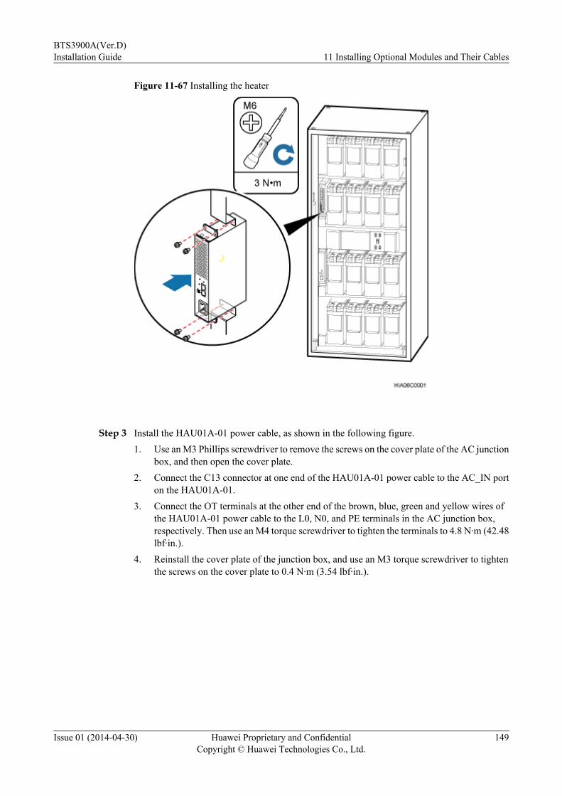
Figure 11-67 Installing the heater
Step 3 Install the HAU01A-01 power cable, as shown in the following figure.1. Use an M3 Phillips screwdriver to remove the screws on the cover plate of the AC junction
box, and then open the cover plate.2. Connect the C13 connector at one end of the HAU01A-01 power cable to the AC_IN port
on the HAU01A-01.3. Connect the OT terminals at the other end of the brown, blue, green and yellow wires of
the HAU01A-01 power cable to the L0, N0, and PE terminals in the AC junction box,respectively. Then use an M4 torque screwdriver to tighten the terminals to 4.8 N·m (42.48lbf·in.).
4. Reinstall the cover plate of the junction box, and use an M3 torque screwdriver to tightenthe screws on the cover plate to 0.4 N·m (3.54 lbf·in.).
BTS3900A(Ver.D)Installation Guide 11 Installing Optional Modules and Their Cables
Issue 01 (2014-04-30) Huawei Proprietary and ConfidentialCopyright © Huawei Technologies Co., Ltd.
149

Figure 11-68 Installing the HAU01A-01 power cable
Step 4 Install the HAU01A-01 monitoring signal cable.1. Connect the bare wires at the other end of the HAU01A-01 monitoring signal cable to the
ALM_ALL port on the HAU01A-01, as shown in the following figure.
NOTE
One end of the HAU01A-01 monitoring signal cable has been connected to the IN0 port on theCMUEA or CMUF before delivery.
BTS3900A(Ver.D)Installation Guide 11 Installing Optional Modules and Their Cables
Issue 01 (2014-04-30) Huawei Proprietary and ConfidentialCopyright © Huawei Technologies Co., Ltd.
150

Figure 11-69 Installing the HAU01A-01 monitoring signal cable
2. Optional: In the scenario where the battery cabinet is used with the BTS3900AL or
TP48600A-H17B1 and configured with a CCU, connect the RJ45 connector at the otherend of the HAU01A-01 monitoring signal cable to the COM_IN port on the HAU01A-01,as shown in the following figure.
NOTE
One end of the HAU01A-01 monitoring signal cable has been connected to the D_COM3 port onthe CCU before delivery.
BTS3900A(Ver.D)Installation Guide 11 Installing Optional Modules and Their Cables
Issue 01 (2014-04-30) Huawei Proprietary and ConfidentialCopyright © Huawei Technologies Co., Ltd.
151

Figure 11-70 Installing the HAU01A-01 monitoring signal cable
Step 5 Lay out the cables according to the instructions in 12.1 Cabling Requirements, and use cableties to bind them.
Step 6 Label the installed cables according to the instructions in Attaching an L-Shaped Label.
----End
BTS3900A(Ver.D)Installation Guide 11 Installing Optional Modules and Their Cables
Issue 01 (2014-04-30) Huawei Proprietary and ConfidentialCopyright © Huawei Technologies Co., Ltd.
152
12 Installing Cables
About This Chapter
Before cabinets used in the BTS3900A are delivered, the boards and cables inside the cabinetshave been installed. You must install the external cables and cables for optional componentsonsite.
12.1 Cabling RequirementsCables must be laid out according to the specified cabling requirements to prevent signalinterference.
12.2 Cable HolesIn a BTS3900A, all cabinets are maintained from the front, and all cables are routed into andout of the cabinets through the cable holes at the bottom of the cabinets. This section describesthe cable holes in the APM30H, TMC11H, RFC, IBBS200D, IBBS200T, IBBS700D, andIBBS700T.
12.3 Installing Power CablesThis chapter describes the procedures and precautions for installing the external power cableand power cables for the modules in the cabinet.
12.4 Installing Transmission CablesThis chapter describes the procedures and precautions for installing transmission cables betweenthe cabinet and external transmission equipment.
12.5 Installing Signal CablesThis chapter describes the procedures and precautions for installing the signal cables.
12.6 Installing RF JumpersRF jumpers transmit signals between the RFUs and antenna system.
12.7 (Optional) Installing the CPRI Electrical CablesThis section describes the procedure for installing CPRI electrical cables. A CPRI electricalcable connects an RFU and a BBU and transmits CPRI signals between them.
12.8 (Optional) Installing the CPRI Fiber Optic CablesA CPRI fiber optic cable connects a BBU and an RRU and transmits CPRI signals betweenthem.
BTS3900A(Ver.D)Installation Guide 12 Installing Cables
Issue 01 (2014-04-30) Huawei Proprietary and ConfidentialCopyright © Huawei Technologies Co., Ltd.
153

12.1 Cabling RequirementsCables must be laid out according to the specified cabling requirements to prevent signalinterference.
NOTE
If a cable listed below is not required, skip the cabling requirements of the cable.
General Cabling Requirements
Bending radius requirements
l The bending radius of a 7/8'' feeder must be greater than 250 mm (9.84 in.), and the bendingradius of a 5/4'' feeder must be greater than 380 mm (14.96 in.).
l The bending radius of a 1/4'' jumper must be greater than 35 mm (1.38 in.). The bendingradius of a super-flexible 1/2'' jumper must be greater than 50 mm (1.97 in.), and the bendingradius of an ordinary 1/2'' jumper must be greater than 127 mm (5 in.).
l The bending radius of a power cable or PGND cable must be at least three times its diameter.
l The bending radius of a fiber optic cable is at least 20 times of its diameter, and the bendingradius of a breakout cable is at least 30 mm (1.18 in.).
l The bending radius of an E1/T1 cable must be at least three times its diameter.
l The bending radius of a signal cable must be at least five times its diameter.
Cable binding requirements
l Cables of the same type must be bound together.
l Different types of cables must be separately laid out and bound, with a minimum distanceof 30 mm (1.18 in.) from each other.
l The cables must be bound tightly and neatly. The sheaths of the cables must not be damaged.
l The cable ties must face the same direction, and those at the same horizontal line must bein a straight line.
l The excess of the indoor cable ties is cut off. The excess of 5 mm (0.197 in.) of the outdoorcable ties is reserved, and the cut surfaces are smooth without sharp edges.
l After cables are installed, labels or nameplates must be attached to the cables at their ends,curves, and interconnection positions.
Security requirements
l When routing cables, avoid sharp objects, for example sharp edges on the wall. If necessary,use tubes to protect the cables.
l When routing cables, keep the cables away from heat sources and use heat insulationmaterials to insulate the cables from the heat sources.
l Reserve a proper distance (0.1 m or 3.937 in. is recommended) between equipment andcables especially at the cable curves to protect the cables and equipment.
Indoor cabling requirements
l Route each cable into the room through the feeder window.
BTS3900A(Ver.D)Installation Guide 12 Installing Cables
Issue 01 (2014-04-30) Huawei Proprietary and ConfidentialCopyright © Huawei Technologies Co., Ltd.
154
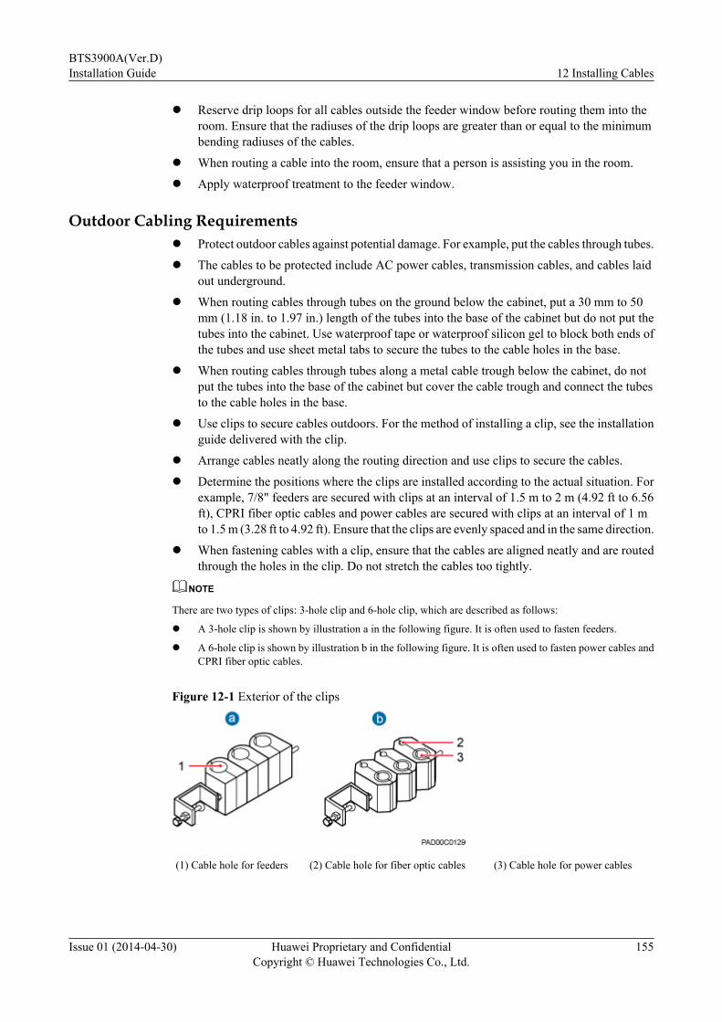
l Reserve drip loops for all cables outside the feeder window before routing them into theroom. Ensure that the radiuses of the drip loops are greater than or equal to the minimumbending radiuses of the cables.
l When routing a cable into the room, ensure that a person is assisting you in the room.
l Apply waterproof treatment to the feeder window.
Outdoor Cabling Requirementsl Protect outdoor cables against potential damage. For example, put the cables through tubes.
l The cables to be protected include AC power cables, transmission cables, and cables laidout underground.
l When routing cables through tubes on the ground below the cabinet, put a 30 mm to 50mm (1.18 in. to 1.97 in.) length of the tubes into the base of the cabinet but do not put thetubes into the cabinet. Use waterproof tape or waterproof silicon gel to block both ends ofthe tubes and use sheet metal tabs to secure the tubes to the cable holes in the base.
l When routing cables through tubes along a metal cable trough below the cabinet, do notput the tubes into the base of the cabinet but cover the cable trough and connect the tubesto the cable holes in the base.
l Use clips to secure cables outdoors. For the method of installing a clip, see the installationguide delivered with the clip.
l Arrange cables neatly along the routing direction and use clips to secure the cables.
l Determine the positions where the clips are installed according to the actual situation. Forexample, 7/8" feeders are secured with clips at an interval of 1.5 m to 2 m (4.92 ft to 6.56ft), CPRI fiber optic cables and power cables are secured with clips at an interval of 1 mto 1.5 m (3.28 ft to 4.92 ft). Ensure that the clips are evenly spaced and in the same direction.
l When fastening cables with a clip, ensure that the cables are aligned neatly and are routedthrough the holes in the clip. Do not stretch the cables too tightly.
NOTE
There are two types of clips: 3-hole clip and 6-hole clip, which are described as follows:
l A 3-hole clip is shown by illustration a in the following figure. It is often used to fasten feeders.
l A 6-hole clip is shown by illustration b in the following figure. It is often used to fasten power cables andCPRI fiber optic cables.
Figure 12-1 Exterior of the clips
(1) Cable hole for feeders (2) Cable hole for fiber optic cables (3) Cable hole for power cables
BTS3900A(Ver.D)Installation Guide 12 Installing Cables
Issue 01 (2014-04-30) Huawei Proprietary and ConfidentialCopyright © Huawei Technologies Co., Ltd.
155
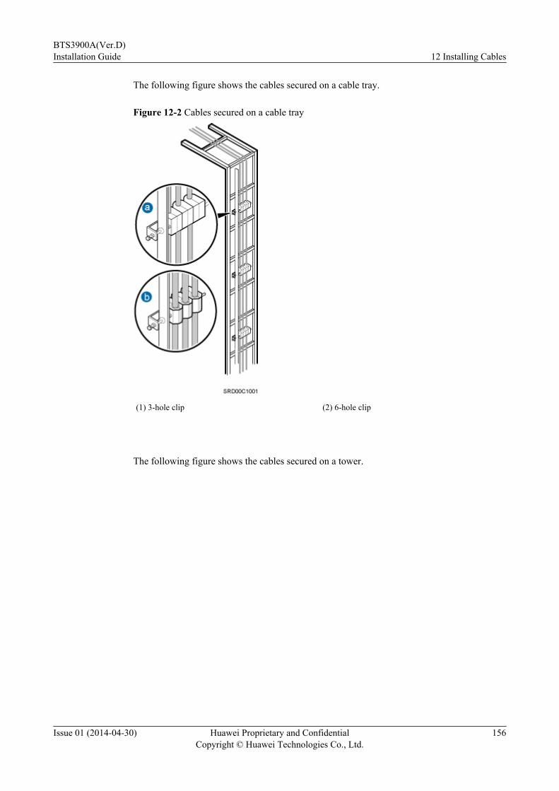
The following figure shows the cables secured on a cable tray.
Figure 12-2 Cables secured on a cable tray
(1) 3-hole clip (2) 6-hole clip
The following figure shows the cables secured on a tower.
BTS3900A(Ver.D)Installation Guide 12 Installing Cables
Issue 01 (2014-04-30) Huawei Proprietary and ConfidentialCopyright © Huawei Technologies Co., Ltd.
156
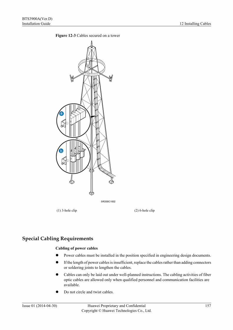
Figure 12-3 Cables secured on a tower
(1) 3-hole clip (2) 6-hole clip
Special Cabling Requirements
Cabling of power cables
l Power cables must be installed in the position specified in engineering design documents.
l If the length of power cables is insufficient, replace the cables rather than adding connectorsor soldering joints to lengthen the cables.
l Cables can only be laid out under well-planned instructions. The cabling activities of fiberoptic cables are allowed only when qualified personnel and communication facilities areavailable.
l Do not circle and twist cables.
BTS3900A(Ver.D)Installation Guide 12 Installing Cables
Issue 01 (2014-04-30) Huawei Proprietary and ConfidentialCopyright © Huawei Technologies Co., Ltd.
157
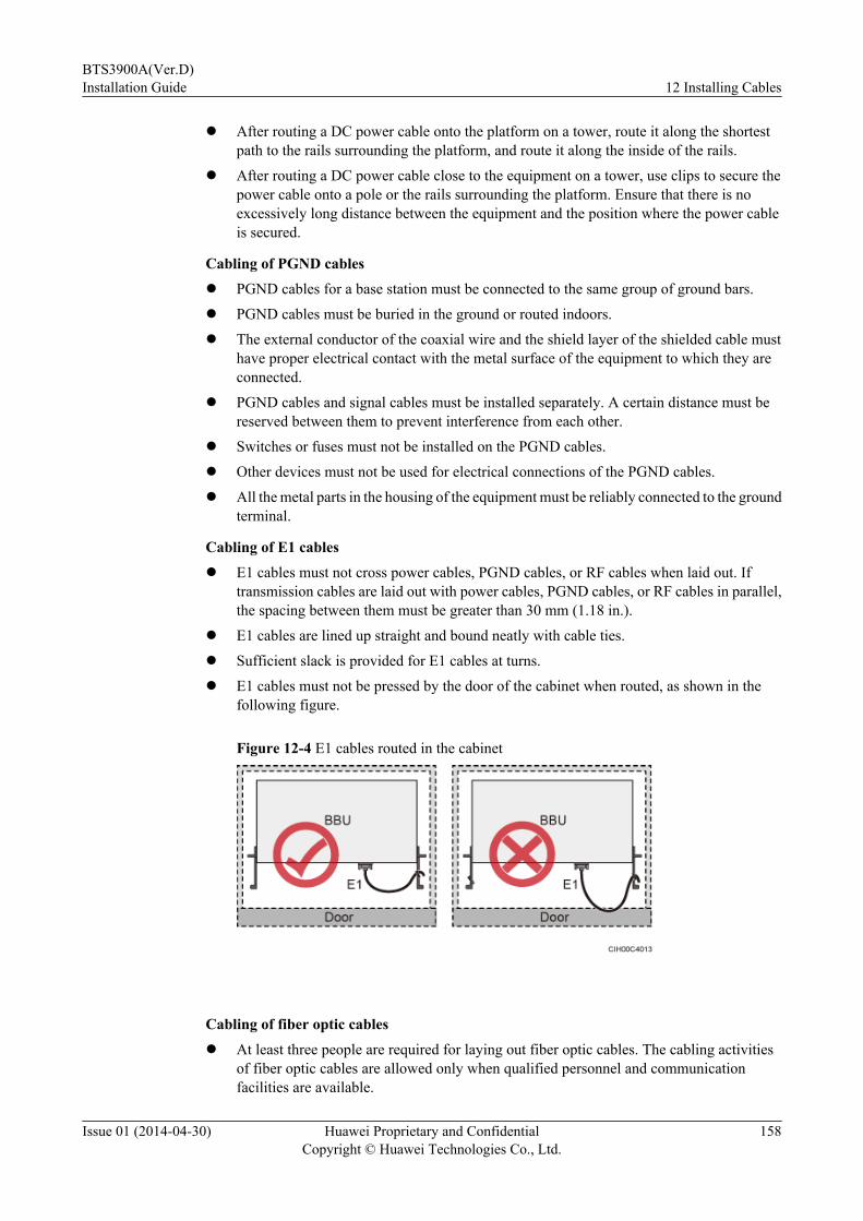
l After routing a DC power cable onto the platform on a tower, route it along the shortestpath to the rails surrounding the platform, and route it along the inside of the rails.
l After routing a DC power cable close to the equipment on a tower, use clips to secure thepower cable onto a pole or the rails surrounding the platform. Ensure that there is noexcessively long distance between the equipment and the position where the power cableis secured.
Cabling of PGND cablesl PGND cables for a base station must be connected to the same group of ground bars.
l PGND cables must be buried in the ground or routed indoors.
l The external conductor of the coaxial wire and the shield layer of the shielded cable musthave proper electrical contact with the metal surface of the equipment to which they areconnected.
l PGND cables and signal cables must be installed separately. A certain distance must bereserved between them to prevent interference from each other.
l Switches or fuses must not be installed on the PGND cables.
l Other devices must not be used for electrical connections of the PGND cables.
l All the metal parts in the housing of the equipment must be reliably connected to the groundterminal.
Cabling of E1 cablesl E1 cables must not cross power cables, PGND cables, or RF cables when laid out. If
transmission cables are laid out with power cables, PGND cables, or RF cables in parallel,the spacing between them must be greater than 30 mm (1.18 in.).
l E1 cables are lined up straight and bound neatly with cable ties.
l Sufficient slack is provided for E1 cables at turns.
l E1 cables must not be pressed by the door of the cabinet when routed, as shown in thefollowing figure.
Figure 12-4 E1 cables routed in the cabinet
Cabling of fiber optic cablesl At least three people are required for laying out fiber optic cables. The cabling activities
of fiber optic cables are allowed only when qualified personnel and communicationfacilities are available.
BTS3900A(Ver.D)Installation Guide 12 Installing Cables
Issue 01 (2014-04-30) Huawei Proprietary and ConfidentialCopyright © Huawei Technologies Co., Ltd.
158
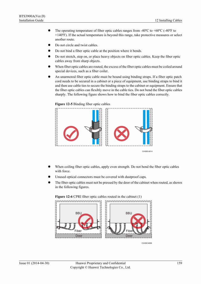
l The operating temperature of fiber optic cables ranges from -40ºC to +60ºC (-40ºF to+140ºF). If the actual temperature is beyond this range, take protective measures or selectanother route.
l Do not circle and twist cables.l Do not bind a fiber optic cable at the position where it bends.l Do not stretch, step on, or place heavy objects on fiber optic cables. Keep the fiber optic
cables away from sharp objects.l When fiber optic cables are routed, the excess of the fiber optic cables must be coiled around
special devices, such as a fiber coiler.l An unarmored fiber optic cable must be bound using binding straps. If a fiber optic patch
cord needs to be secured in a cabinet or a piece of equipment, use binding straps to bind itand then use cable ties to secure the binding straps to the cabinet or equipment. Ensure thatthe fiber optic cables can flexibly move in the cable ties. Do not bend the fiber optic cablessharply. The following figure shows how to bind the fiber optic cables correctly.
Figure 12-5 Binding fiber optic cables
l When coiling fiber optic cables, apply even strength. Do not bend the fiber optic cables
with force.l Unused optical connectors must be covered with dustproof caps.l The fiber optic cables must not be pressed by the door of the cabinet when routed, as shown
in the following figures.
Figure 12-6 CPRI fiber optic cables routed in the cabinet (1)
BTS3900A(Ver.D)Installation Guide 12 Installing Cables
Issue 01 (2014-04-30) Huawei Proprietary and ConfidentialCopyright © Huawei Technologies Co., Ltd.
159

Figure 12-7 CPRI fiber optic cables routed in the cabinet (2)
Figure 12-8 FE/GE fiber optic cables routed in the cabinet
l After routing a fiber optic cable onto the platform on a tower, route it along the shortestpath to the rails surrounding the platform, and route it along the inside of the rails.
l After routing a fiber optic cable close to the equipment on a tower, use clips to secure thefiber optic cable onto a pole or the rails surrounding the platform. Ensure that there is noexcessively long distance between the equipment and the position where the cable issecured.
l Coil the excess of the fiber optic cables near the equipment on the tower before securingthe cables on the tower.
12.2 Cable HolesIn a BTS3900A, all cabinets are maintained from the front, and all cables are routed into andout of the cabinets through the cable holes at the bottom of the cabinets. This section describesthe cable holes in the APM30H, TMC11H, RFC, IBBS200D, IBBS200T, IBBS700D, andIBBS700T.
Cable Holes in an APM30H, TMC11H, or IBBS200D/IBBS200T
The following figure shows a planform for the cable holes at the bottom of an APM30H,TMC11H, or IBBS200D/IBBS200T.
BTS3900A(Ver.D)Installation Guide 12 Installing Cables
Issue 01 (2014-04-30) Huawei Proprietary and ConfidentialCopyright © Huawei Technologies Co., Ltd.
160

Figure 12-9 Planform for the cable holes in the APM30H, TMC11H, or IBBS200D/IBBS200T
(1) Left cable hole (2) Right cable hole
Cable bags are used in the cable holes of the APM30H, TMC11H, and IBBS200D/IBBS200T.This facilitates the cabling of all types of cables. The following figure uses an APM30H as anexample.
Figure 12-10 Cable bags in an APM30H, TMC11H, or IBBS200D/IBBS200T
The following table describes the cable routing through the cable holes in an APM30H.
BTS3900A(Ver.D)Installation Guide 12 Installing Cables
Issue 01 (2014-04-30) Huawei Proprietary and ConfidentialCopyright © Huawei Technologies Co., Ltd.
161

Table 12-1 Cable routing through the cable holes in an APM30H
Item Description
Leftcablehole
Cables routed through this cable hole are as follows: the APM30H input power cable,inter-cabinet equipotential cable, heating film power cable in an IBBS200D, powercable for the AC junction box in a TMC11H, E1/T1 cable, CPRI electrical cable,CPRI fiber optic cable, GPS signal cable, GPS jumper, and monitoring signal cablefor a battery cabinet.
Rightcablehole
Cables routed through this cable hole are as follows: the RFC power cable, TMC11Hinput power cable, storage battery power cable, power cable for the fan in anIBBS200D, power cable for the TEC in the IBBS200T, CPRI electrical cable, CPRIfiber optic cable, FE/GE Ethernet cable, FE/GE fiber optic cable, RGPS signal cable,1PPS+TOD signal cable, and CMUEA-BBU monitoring signal cable.
The following table describes the cable routing through the cable holes in a TMC11H.
Table 12-2 Cable routing through the cable holes in a TMC11H
Item Description
Leftcablehole
Cables routed through this cable hole are as follows: the AC input and output powercable, power cable for the AC junction box in a TMC11H, inter-cabinet equipotentialcable, E1/T1 cable, CPRI electrical cable, CPRI fiber optic cable, GPS signal cable,and GPS jumper.
Rightcablehole
Cables routed through this cable hole are as follows: the TMC11H input power cable,monitoring signal cable between cascaded CMUEAs (in the RFC and TMC11H), FEcable, FE/GE Ethernet cable, FE/GE fiber optic cable, RGPS signal cable, 1PPS+TOD signal cable, and CMUEA-BBU monitoring signal cable.
The following table describes the cable routing through the cable holes in an IBBS200D orIBBS200T.
Table 12-3 Cabling through the cable holes in an IBBS200D or IBBS200T
Item Description
Leftcablehole
Cables routed through this cable hole are as follows: the power cable for the ACjunction box in an TMC11H, inter-cabinet equipotential cable, heating film powercable in an IBBS200D, battery cabinet monitoring signal cable, and monitoring signalcable between the cascaded CMUEAs (in different battery cabinets).
Rightcablehole
Cables routed through this cable hole are as follows: the TMC11H input power cable,storage battery power cable, storage battery cascading power cable, power cable forthe TEC in an IBBS200T, and power cable for the fan in an IBBS200D.
BTS3900A(Ver.D)Installation Guide 12 Installing Cables
Issue 01 (2014-04-30) Huawei Proprietary and ConfidentialCopyright © Huawei Technologies Co., Ltd.
162
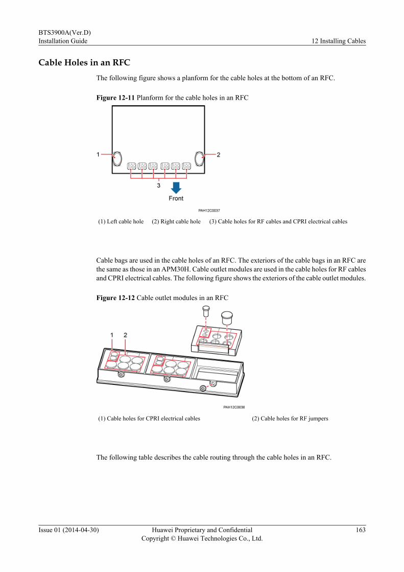
Cable Holes in an RFCThe following figure shows a planform for the cable holes at the bottom of an RFC.
Figure 12-11 Planform for the cable holes in an RFC
(1) Left cable hole (2) Right cable hole (3) Cable holes for RF cables and CPRI electrical cables
Cable bags are used in the cable holes of an RFC. The exteriors of the cable bags in an RFC arethe same as those in an APM30H. Cable outlet modules are used in the cable holes for RF cablesand CPRI electrical cables. The following figure shows the exteriors of the cable outlet modules.
Figure 12-12 Cable outlet modules in an RFC
(1) Cable holes for CPRI electrical cables (2) Cable holes for RF jumpers
The following table describes the cable routing through the cable holes in an RFC.
BTS3900A(Ver.D)Installation Guide 12 Installing Cables
Issue 01 (2014-04-30) Huawei Proprietary and ConfidentialCopyright © Huawei Technologies Co., Ltd.
163
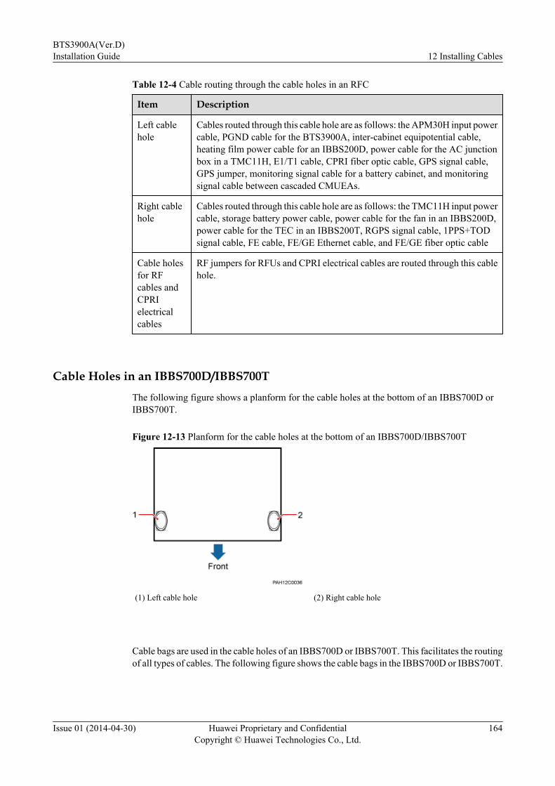
Table 12-4 Cable routing through the cable holes in an RFC
Item Description
Left cablehole
Cables routed through this cable hole are as follows: the APM30H input powercable, PGND cable for the BTS3900A, inter-cabinet equipotential cable,heating film power cable for an IBBS200D, power cable for the AC junctionbox in a TMC11H, E1/T1 cable, CPRI fiber optic cable, GPS signal cable,GPS jumper, monitoring signal cable for a battery cabinet, and monitoringsignal cable between cascaded CMUEAs.
Right cablehole
Cables routed through this cable hole are as follows: the TMC11H input powercable, storage battery power cable, power cable for the fan in an IBBS200D,power cable for the TEC in an IBBS200T, RGPS signal cable, 1PPS+TODsignal cable, FE cable, FE/GE Ethernet cable, and FE/GE fiber optic cable
Cable holesfor RFcables andCPRIelectricalcables
RF jumpers for RFUs and CPRI electrical cables are routed through this cablehole.
Cable Holes in an IBBS700D/IBBS700TThe following figure shows a planform for the cable holes at the bottom of an IBBS700D orIBBS700T.
Figure 12-13 Planform for the cable holes at the bottom of an IBBS700D/IBBS700T
(1) Left cable hole (2) Right cable hole
Cable bags are used in the cable holes of an IBBS700D or IBBS700T. This facilitates the routingof all types of cables. The following figure shows the cable bags in the IBBS700D or IBBS700T.
BTS3900A(Ver.D)Installation Guide 12 Installing Cables
Issue 01 (2014-04-30) Huawei Proprietary and ConfidentialCopyright © Huawei Technologies Co., Ltd.
164

Figure 12-14 Cable bags in an IBBS700D/IBBS700T
The following table describes the cable routing through the cable holes in an IBBS700D orIBBS700T.
Table 12-5 Cabling through the cable holes in an IBBS700D/IBBS700T
Item Note
Leftcablehole
Cables routed through this cable hole are as follows: the PGND cable, power cablefor the AC junction box, power cable for the power distribution box, CCU monitoringsignal cable, and battery cabinet monitoring signal cable.
Rightcablehole
Cables routed through this cable hole are as follows: power cable for the temperaturecontrol system and power cables connected to the power distribution box.
12.3 Installing Power CablesThis chapter describes the procedures and precautions for installing the external power cableand power cables for the modules in the cabinet.
12.3.1 Installing Power Cables for AC CabinetsThis section describes the procedure and precautions for installing power cables for variouscabinets when AC power is supplied.
Installing Input Power Cables for the APM30H
In an APM30H (Ver.D), the input power cables for the APM30H refer to EPU05A-02 orEPU05A-04 power cables. The cables feed power into the EPU05A-02 or EPU05A-04 in theAPM30H (Ver.D) from the external power equipment.
BTS3900A(Ver.D)Installation Guide 12 Installing Cables
Issue 01 (2014-04-30) Huawei Proprietary and ConfidentialCopyright © Huawei Technologies Co., Ltd.
165
Prerequisitesl The following tools are available: a Phillips screwdriver, a torque screwdriver, a cable
cutter, and a multi-purpose crimping tool.
l The PGND cable for the cabinet has been installed.
l The external power supply to the APM30H has been shut off.
Contextl Before the BTS3900A cabinets are delivered, the boards and power cables inside the
cabinets have been installed. You must install input power cables onsite.
l The colors and structures of the power cables in this document are for reference only, whichmay differ from those of the cables onsite.
l The colors and structures of cables vary according to countries and regions. If cables arepurchased locally, the cables must comply with local rules and regulations.
l Contact with Huawei engineers to confirm the following issues:
– The cables and connectors are provided by the customer.
– Some cables of fixed lengths need to be shortened.
The APM30H (Ver.D) supports 220 V AC three-phase, 220 V AC single-phase, and 110 V dual-live-wire power supplies, which require different types of input power cables for the APM30H,as listed in the following table.
Table 12-6 Specifications of the input power cables for the APM30H (Ver.D)
Cable One End The OtherEnd
Color
EPU05A-02 orEPU05A-04 powercables in a 220 V ACthree-phase scenario
L1 OT terminal (M6, 6mm2 or 0.009 in.2)
Depending onthe externalequipment
Brown
L2 Black
L3 Gray
N Blue
EPU05A-02 orEPU05A-04 powercables in a 220 V ACsingle-phase scenario
L OT terminal (M6, 25mm2 or 0.039 in.2)
Depending onthe externalequipment
Brown
N Blue
EPU05A-02 orEPU05A-04 powercables in a 110 V dual-live-wire scenario
L1 OT terminal (M6, 25mm2 or 0.039 in.2)
Depending onthe externalequipment
Black
L2 Red
N White
Procedure
Step 1 Prepare EPU05A-02 or EPU05A-04 power cables.
BTS3900A(Ver.D)Installation Guide 12 Installing Cables
Issue 01 (2014-04-30) Huawei Proprietary and ConfidentialCopyright © Huawei Technologies Co., Ltd.
166

1. Cut the cables to the length suitable for the actual cable route.2. Add M6 OT terminals to the cables on the EPU side according to the instructions in
Assembling the OT Terminal and the Power Cable.
Step 2 Install the EPU05A-02 or EPU05A-04 power cables, as shown in Figure 12-15, Figure12-16, or Figure 12-17.1. Use a Phillips screwdriver to remove an M3 screw from the protective cover for the AC
input terminals, and open the protective cover.2. Optional: Remove the short-circuiting bar on the L1, L2, and L3 input terminals. If 220
V single-phase or 110 V dual-live wire power is supplied, skip this step.3. Route the power cables into the cabinet along the inner left side of the cabinet, connect
each wire to the corresponding terminal, and use a torque screwdriver to tighten the screwsto 4.8 N·m (42.48 lbf·in.).
4. Reinstall the protective covers for the AC input terminals, and tighten the screws on theprotective covers to 0.25 N·m (2.21 lbf·in.).
Figure 12-15 Installing the input power cables for the APM30H on the EPU side (220 V ACthree-phase)
(1) Short-circuiting bar
BTS3900A(Ver.D)Installation Guide 12 Installing Cables
Issue 01 (2014-04-30) Huawei Proprietary and ConfidentialCopyright © Huawei Technologies Co., Ltd.
167
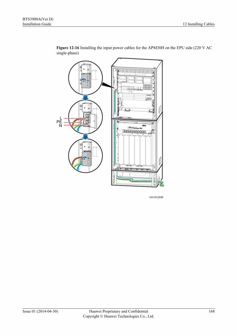
Figure 12-16 Installing the input power cables for the APM30H on the EPU side (220 V ACsingle-phase)
BTS3900A(Ver.D)Installation Guide 12 Installing Cables
Issue 01 (2014-04-30) Huawei Proprietary and ConfidentialCopyright © Huawei Technologies Co., Ltd.
168
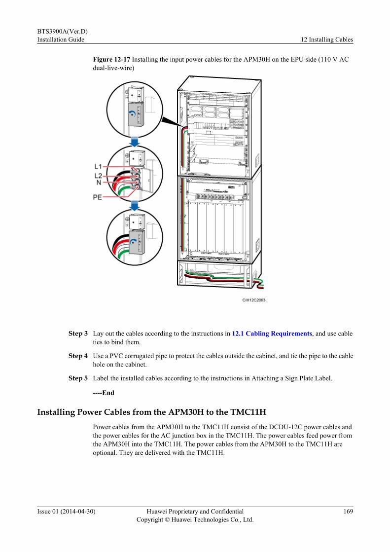
Figure 12-17 Installing the input power cables for the APM30H on the EPU side (110 V ACdual-live-wire)
Step 3 Lay out the cables according to the instructions in 12.1 Cabling Requirements, and use cableties to bind them.
Step 4 Use a PVC corrugated pipe to protect the cables outside the cabinet, and tie the pipe to the cablehole on the cabinet.
Step 5 Label the installed cables according to the instructions in Attaching a Sign Plate Label.
----End
Installing Power Cables from the APM30H to the TMC11HPower cables from the APM30H to the TMC11H consist of the DCDU-12C power cables andthe power cables for the AC junction box in the TMC11H. The power cables feed power fromthe APM30H into the TMC11H. The power cables from the APM30H to the TMC11H areoptional. They are delivered with the TMC11H.
BTS3900A(Ver.D)Installation Guide 12 Installing Cables
Issue 01 (2014-04-30) Huawei Proprietary and ConfidentialCopyright © Huawei Technologies Co., Ltd.
169

Prerequisitesl The following tools are available: a Phillips screwdriver, a torque screwdriver, a cable
cutter, and a multi-purpose crimping tool.
l The PGND cable for the cabinet has been installed.
Contextl Before the BTS3900A cabinets are delivered, the boards and power cables inside the
cabinets have been installed. You must install input power cables onsite.
l The colors and structures of the power cables in this document are for reference only, whichmay differ from those of the cables onsite.
l The colors and structures of cables vary according to countries and regions. If cables arepurchased locally, the cables must comply with local rules and regulations.
l Contact with Huawei engineers to confirm the following issues:
– The cables and connectors are provided by the customer.
– Some cables of fixed lengths need to be shortened.
The following table lists the specifications of the power cables from the APM30H to theTMC11H.
Table 12-7 Specifications of power cables from the APM30H to the TMC11H
Cable One End The Other End Color
DCDU-12Cpower cables
RTN(+) EPC4 connector OT terminal (M6, 4mm2 or 0.006 in.2)
Black
NEG(-) Blue
Power cables foran AC junctionbox
L OT terminal (M4, 1.5mm2 or 0.002 in.2)
OT terminal (M4, 1.5mm2 or 0.002 in.2)
Brown
N Blue
Procedure
Step 1 Prepare the DCDU-12C power cables and the power cables for the AC junction box in theTMC11H.
1. Cut the cables to the length suitable for the actual cable route.
2. Add a connector or terminals to each end of the power cables according to the precedingtable.
l For the power cables for the AC junction box in the TMC11H, see Assembling the OTTerminal and the Power Cable.
l For the DCDU-12C power cables, see Assembling the EPC4 Connector and the PowerCable.
Step 2 Install the DCDU-12C power cables, as shown in the following figure.
1. Open the protective cover for the power input terminals.
BTS3900A(Ver.D)Installation Guide 12 Installing Cables
Issue 01 (2014-04-30) Huawei Proprietary and ConfidentialCopyright © Huawei Technologies Co., Ltd.
170

2. Connect the OT terminals at one end of the power cables to the RTN(+) and NEG(-)terminals on the DCDU-12C in the TMC11H, and tighten the screws on the OT terminalsto 4.8 N·m (42.48 lbf·in.).
3. Connect the EPC4 connector at the other end of the power cables to the LOAD7 port onthe EPU in the APM30H.
4. Reinstall the protective cover, and use a torque screwdriver to tighten the screw on theprotective cover to 0.3 N·m (2.66 lbf·in.).
CAUTIONEnsure that the TMC11H power cable for a TMC11H added to a running base station must beconnected to the TMC11H first and then to the APM30H. The operations in the reverse sequencemay cause component damage or personal injury.
Figure 12-18 Installing the DCDU-12C power cables
Step 3 Install the power cables for the AC junction box in the TMC11H, as shown in the followingfigure.
BTS3900A(Ver.D)Installation Guide 12 Installing Cables
Issue 01 (2014-04-30) Huawei Proprietary and ConfidentialCopyright © Huawei Technologies Co., Ltd.
171
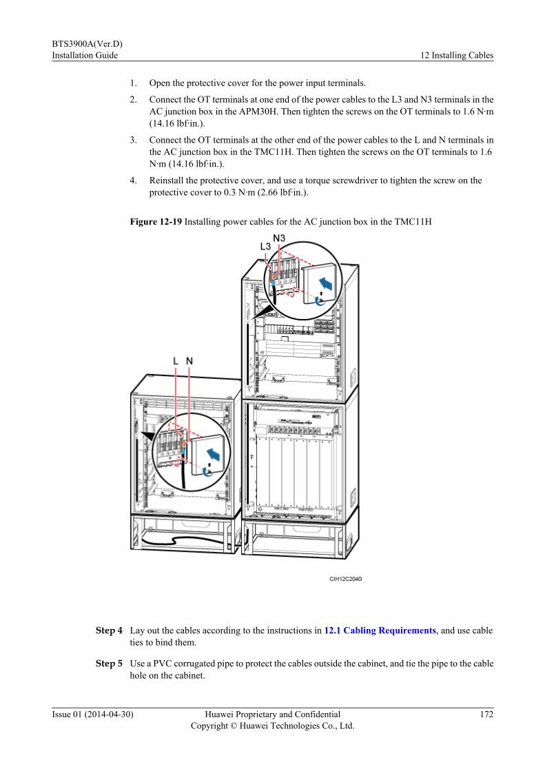
1. Open the protective cover for the power input terminals.
2. Connect the OT terminals at one end of the power cables to the L3 and N3 terminals in theAC junction box in the APM30H. Then tighten the screws on the OT terminals to 1.6 N·m(14.16 lbf·in.).
3. Connect the OT terminals at the other end of the power cables to the L and N terminals inthe AC junction box in the TMC11H. Then tighten the screws on the OT terminals to 1.6N·m (14.16 lbf·in.).
4. Reinstall the protective cover, and use a torque screwdriver to tighten the screw on theprotective cover to 0.3 N·m (2.66 lbf·in.).
Figure 12-19 Installing power cables for the AC junction box in the TMC11H
Step 4 Lay out the cables according to the instructions in 12.1 Cabling Requirements, and use cableties to bind them.
Step 5 Use a PVC corrugated pipe to protect the cables outside the cabinet, and tie the pipe to the cablehole on the cabinet.
BTS3900A(Ver.D)Installation Guide 12 Installing Cables
Issue 01 (2014-04-30) Huawei Proprietary and ConfidentialCopyright © Huawei Technologies Co., Ltd.
172

Step 6 Label the installed cables according to the instructions in Attaching a Sign Plate Label.
----End
Installing Power Cables from the APM30H to RFCs
When two RFCs are configured in the BTS3900A, you need to install the power cables from theAPM30H to the extension RFC onsite.
Prerequisitesl The following tools are available: a Phillips screwdriver, a torque screwdriver, a cable
cutter, and a multi-purpose crimping tool.
l The PGND cable for the cabinet has been installed.
Contextl Before the BTS3900A cabinets are delivered, the boards and power cables inside the
cabinets have been installed. You must install input power cables onsite.
l The colors and structures of the power cables in this document are for reference only, whichmay differ from those of the cables onsite.
l The colors and structures of cables vary according to countries and regions. If cables arepurchased locally, the cables must comply with local rules and regulations.
l Contact with Huawei engineers to confirm the following issues:
– The cables and connectors are provided by the customer.
– Some cables of fixed lengths need to be shortened.
The following table lists the specifications of power cables from the APM30H to RFCs.
Table 12-8 Specifications of power cables from the APM30H to RFCs
Cable One End The Other End Color
Power cables forthe DC junctionbox
RTN(+) OT terminal (M6, 25mm2 or 0.039 in.2)
OT terminal (M6, 25mm2 or 0.039 in.2)
Black
NEG(-) Blue
Procedure
Step 1 Prepare the power cables for the DC junction box.
1. Cut the cables to the length suitable for the actual cable route.
2. Add OT terminals to both ends of the power cables according to the preceding table. Fordetails about how to add the OT terminals, see Assembling the OT Terminal and the PowerCable.
Step 2 Install the power cables for the DC junction box, as shown in the following figure.
1. Open the protective cover for the power input terminals.
BTS3900A(Ver.D)Installation Guide 12 Installing Cables
Issue 01 (2014-04-30) Huawei Proprietary and ConfidentialCopyright © Huawei Technologies Co., Ltd.
173
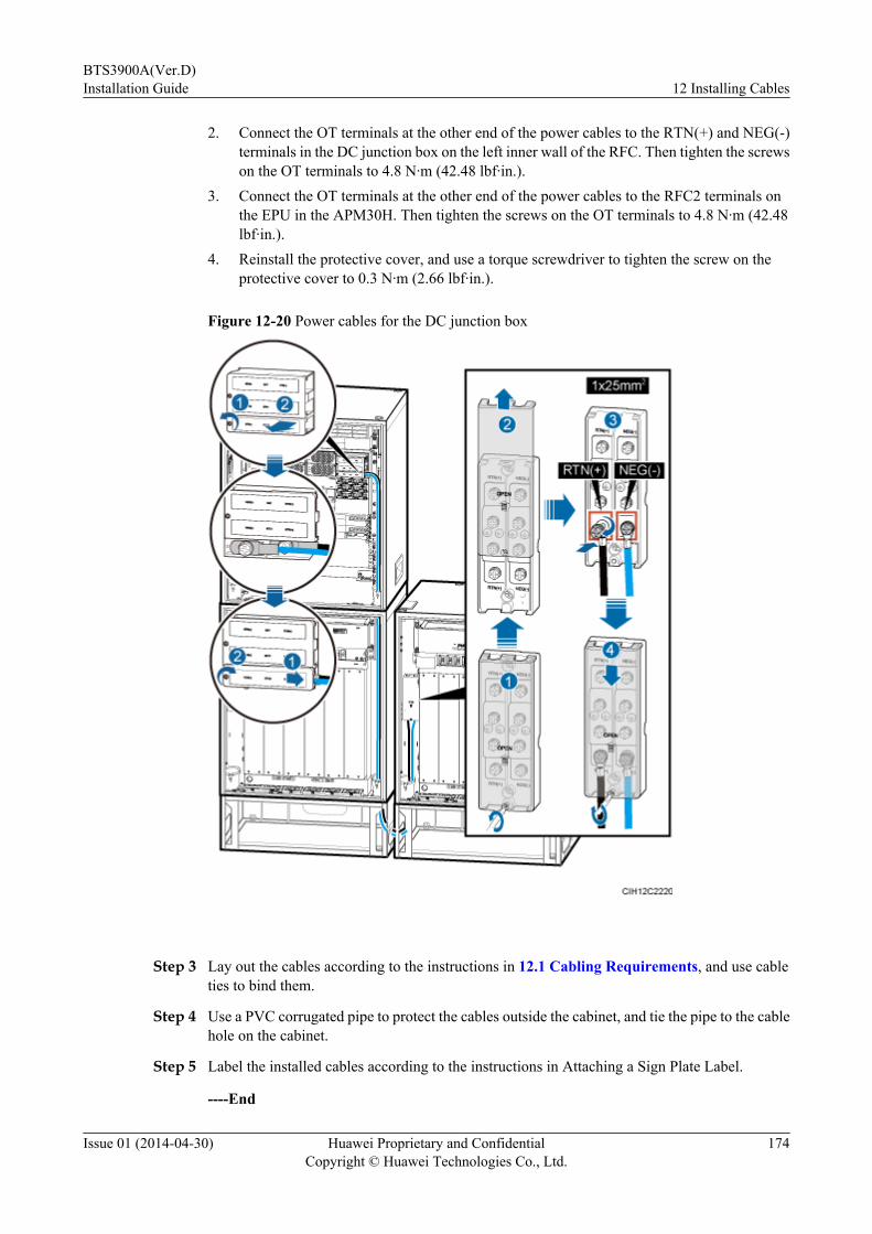
2. Connect the OT terminals at the other end of the power cables to the RTN(+) and NEG(-)terminals in the DC junction box on the left inner wall of the RFC. Then tighten the screwson the OT terminals to 4.8 N·m (42.48 lbf·in.).
3. Connect the OT terminals at the other end of the power cables to the RFC2 terminals onthe EPU in the APM30H. Then tighten the screws on the OT terminals to 4.8 N·m (42.48lbf·in.).
4. Reinstall the protective cover, and use a torque screwdriver to tighten the screw on theprotective cover to 0.3 N·m (2.66 lbf·in.).
Figure 12-20 Power cables for the DC junction box
Step 3 Lay out the cables according to the instructions in 12.1 Cabling Requirements, and use cableties to bind them.
Step 4 Use a PVC corrugated pipe to protect the cables outside the cabinet, and tie the pipe to the cablehole on the cabinet.
Step 5 Label the installed cables according to the instructions in Attaching a Sign Plate Label.
----End
BTS3900A(Ver.D)Installation Guide 12 Installing Cables
Issue 01 (2014-04-30) Huawei Proprietary and ConfidentialCopyright © Huawei Technologies Co., Ltd.
174
Installing the Power Cables from the APM30H to the IBBS200D or IBBS200T (OneIBBS200D or IBBS200T Configured)
This section describes the procedure for installing the power cables from the APM30H to theIBBS200D or IBBS200T when one IBBS200D or IBBS200T is configured in the initialconfiguration.
Prerequisitesl The following tools are available: a Phillips screwdriver, a torque screwdriver, a cable
cutter, and a multi-purpose crimping tool.
l The PGND cable for the cabinet has been installed.
Contextl Before the BTS3900A cabinets are delivered, the boards and power cables inside the
cabinets have been installed. You must install input power cables onsite.
l The colors and structures of the power cables in this document are for reference only, whichmay differ from those of the cables onsite.
l The colors and structures of cables vary according to countries and regions. If cables arepurchased locally, the cables must comply with local rules and regulations.
l Contact with Huawei engineers to confirm the following issues:
– The cables and connectors are provided by the customer.
– Some cables of fixed lengths need to be shortened.
l A site can only be configured with either the IBBS200D or IBBS200T.
The following table lists the specifications of power cables from the APM30H to the IBBS200Dor IBBS200T.
Table 12-9 Specifications of power cables from the APM30H to the IBBS200D or IBBS200T
Cable One End The Other End Color
Fan power cablesin an IBBS200DTEC powercables in anIBBS200T
RTN(+) EPC4 connector EPC4 connector Black
NEG(-) Blue
Power cables forthe IBBS200D orIBBS200T
RTN(+) OT terminal (M8, 35mm2 or 0.054 in.2)
OT terminal (M8, 35mm2 or 0.054 in.2)
Red
NEG(-) Black
Heating-filmpower cables inan IBBS200D
L OT terminal (M4, 1.5mm2 or 0.002 in.2)
OT terminal (M4, 1.5mm2 or 0.002 in.2)
Brown
N Blue
BTS3900A(Ver.D)Installation Guide 12 Installing Cables
Issue 01 (2014-04-30) Huawei Proprietary and ConfidentialCopyright © Huawei Technologies Co., Ltd.
175
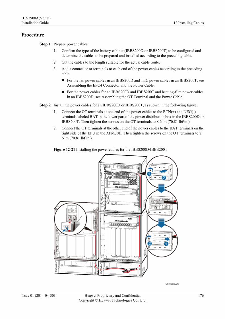
Procedure
Step 1 Prepare power cables.
1. Confirm the type of the battery cabinet (IBBS200D or IBBS200T) to be configured anddetermine the cables to be prepared and installed according to the preceding table.
2. Cut the cables to the length suitable for the actual cable route.
3. Add a connector or terminals to each end of the power cables according to the precedingtable.
l For the fan power cables in an IBBS200D and TEC power cables in an IBBS200T, seeAssembling the EPC4 Connector and the Power Cable.
l For the power cables for an IBBS200D and IBBS200T and heating-film power cablesin an IBBS200D, see Assembling the OT Terminal and the Power Cable.
Step 2 Install the power cables for an IBBS200D or IBBS200T, as shown in the following figure.
1. Connect the OT terminals at one end of the power cables to the RTN(+) and NEG(-)terminals labeled BAT in the lower part of the power distribution box in the IBBS200D orIBBS200T. Then tighten the screws on the OT terminals to 8 N·m (70.81 lbf·in.).
2. Connect the OT terminals at the other end of the power cables to the BAT terminals on theright side of the EPU in the APM30H. Then tighten the screws on the OT terminals to 8N·m (70.81 lbf·in.).
Figure 12-21 Installing the power cables for the IBBS200D/IBBS200T
BTS3900A(Ver.D)Installation Guide 12 Installing Cables
Issue 01 (2014-04-30) Huawei Proprietary and ConfidentialCopyright © Huawei Technologies Co., Ltd.
176

Step 3 Optional: Install the fan power cables in the IBBS200D. If no IBBS200D is configured, skipthis step.
1. Connect the EPC4 connector at the other end of the power cable to the INPUT port nearthe FAN/TEC silkscreen in the middle of the power distribution box in the IBBS200D.
2. Connect the EPC4 connector at the other end of the power cables to the LOAD8 port onthe right side of the EPU in the APM30H.
Figure 12-22 Installing the fan power cables in the IBBS200D
Step 4 Optional: Install the heating-film power cables in the IBBS200D. Skip this step if no IBBS200Dis configured or no heating film is configured in the IBBS200D.
1. Open the protective cover for the power input terminals.
2. Open the cover plate of the AC junction box.
3. Connect the OT terminals at one end of the power cables to the L2 and N2 terminals in theAC junction box on the left inner wall of the APM30H. Then tighten the screws on the OTterminals to 1.6 N·m (14.16 lbf·in.).
BTS3900A(Ver.D)Installation Guide 12 Installing Cables
Issue 01 (2014-04-30) Huawei Proprietary and ConfidentialCopyright © Huawei Technologies Co., Ltd.
177

4. Connect the OT terminals at the other end of the power cables to the L and N terminals inthe heating-film AC junction box on the left inner wall in the IBBS200D. Then tighten thescrews on the OT terminals to 0.3 N·m (2.66 lbf·in.).
5. Reinstall the protective cover for the power input terminals, and tighten the screws to 0.3N·m (2.66 lbf·in.).
6. Reinstall the cover plate of the AC junction box, and tighten the screws to 0.3 N·m (2.66lbf·in.).
NOTICEWhen installing the heating-film power cables in the heating-film AC junction box in theIBBS200D, do not connect the cables in the manners shown in the following figure.l Do not expose the wires of the heating-film power cables outside the heating-film AC
junction box.l The heating-film power cables must be routed into the heating-film AC junction box from
the top, not from the bottom.
Figure 12-23 Incorrect connections of the heating-film power cables in the heating-film ACjunction box in the IBBS200D
BTS3900A(Ver.D)Installation Guide 12 Installing Cables
Issue 01 (2014-04-30) Huawei Proprietary and ConfidentialCopyright © Huawei Technologies Co., Ltd.
178
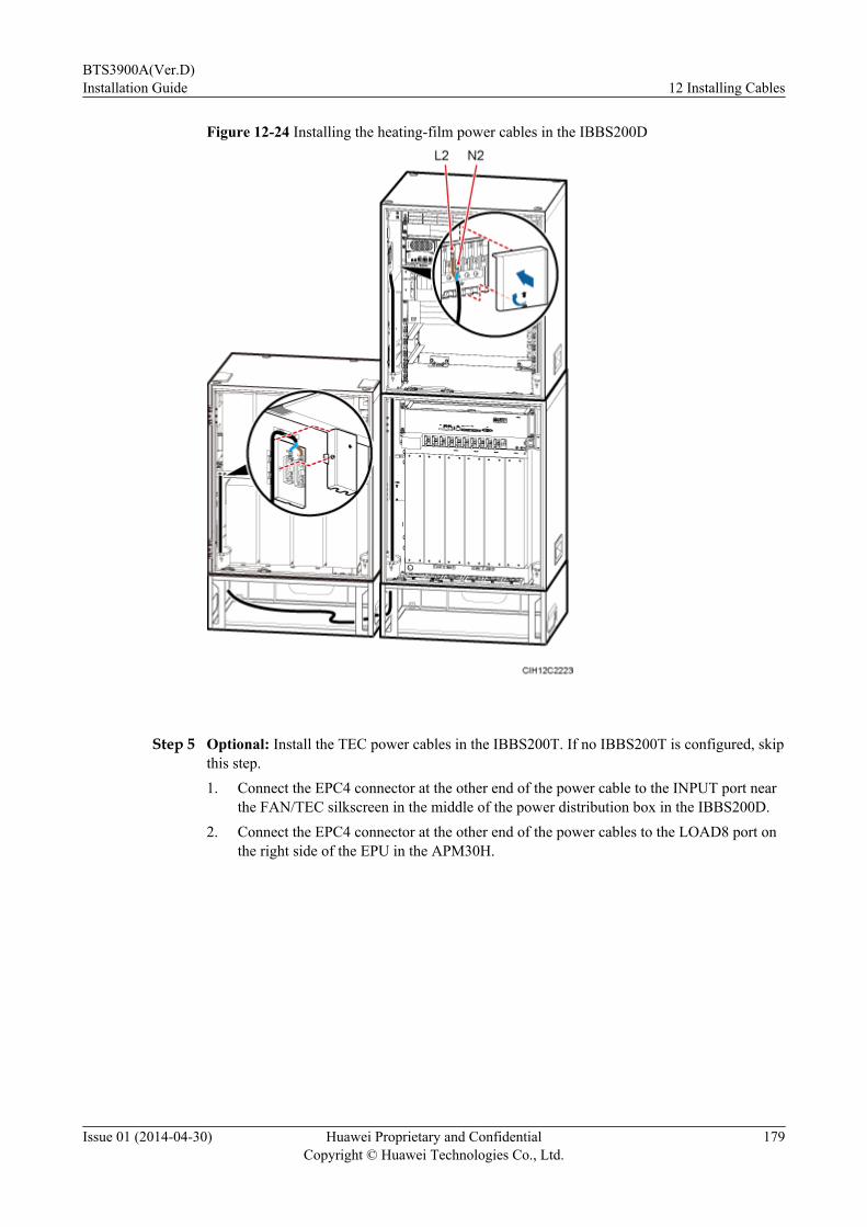
Figure 12-24 Installing the heating-film power cables in the IBBS200D
Step 5 Optional: Install the TEC power cables in the IBBS200T. If no IBBS200T is configured, skipthis step.1. Connect the EPC4 connector at the other end of the power cable to the INPUT port near
the FAN/TEC silkscreen in the middle of the power distribution box in the IBBS200D.2. Connect the EPC4 connector at the other end of the power cables to the LOAD8 port on
the right side of the EPU in the APM30H.
BTS3900A(Ver.D)Installation Guide 12 Installing Cables
Issue 01 (2014-04-30) Huawei Proprietary and ConfidentialCopyright © Huawei Technologies Co., Ltd.
179

Figure 12-25 Installing TEC power cables in the IBBS200T
Step 6 Lay out the cables according to the instructions in 12.1 Cabling Requirements, and use cableties to bind them.
Step 7 Use a PVC corrugated pipe to protect the cables outside the cabinet, and tie the pipe to the cablehole on the cabinet.
Step 8 Label the installed cables according to the instructions in Attaching a Sign Plate Label.
----End
Installing the Power Cables from the APM30H to the IBBS200D or IBBS200T (TwoIBBS200Ds or IBBS200Ts Configured)
This section describes the procedure for installing the power cables from the APM30H to thetwo IBBS200Ds or IBBS200Ts configured in the initial configuration.
Prerequisitesl The following tools are available: a Phillips screwdriver, a torque screwdriver, a cable
cutter, and a multi-purpose crimping tool.
BTS3900A(Ver.D)Installation Guide 12 Installing Cables
Issue 01 (2014-04-30) Huawei Proprietary and ConfidentialCopyright © Huawei Technologies Co., Ltd.
180
l The PGND cable for the cabinet has been installed.
Contextl Before the BTS3900A cabinets are delivered, the boards and power cables inside the
cabinets have been installed. You must install input power cables onsite.l The colors and structures of the power cables in this document are for reference only, which
may differ from those of the cables onsite.l The colors and structures of cables vary according to countries and regions. If cables are
purchased locally, the cables must comply with local rules and regulations.l Contact with Huawei engineers to confirm the following issues:
– The cables and connectors are provided by the customer.– Some cables of fixed lengths need to be shortened.
l A site can only be configured with either the IBBS200D or IBBS200T.
The following table lists the specifications of power cables from the APM30H to the IBBS200Dor IBBS200T.
Table 12-10 Specifications of power cables from the APM30H to the IBBS200D or IBBS200T
Cable One End The Other End Color
Fan power cablesin an IBBS200DFan power cablesbetweencascadedIBBS200DsTEC powercables in anIBBS200TTEC powercables betweencascadedIBBS200Ts
RTN(+) EPC4 connector EPC4 connector Black
NEG(-) Blue
Power cables forthe IBBS200D orIBBS200TPower cablesbetweencascadedIBBS200Ds orIBBS200Ts
RTN(+) OT terminal (M8, 35mm2 or 0.054 in.2)
OT terminal (M8, 35mm2 or 0.054 in.2)
Red
NEG(-) Black
Heating-filmpower cables(two) in anIBBS200D
L OT terminal (M4, 1.5mm2 or 0.002 in.2)
OT terminal (M4, 1.5mm2 or 0.002 in.2)
Brown
N Blue
BTS3900A(Ver.D)Installation Guide 12 Installing Cables
Issue 01 (2014-04-30) Huawei Proprietary and ConfidentialCopyright © Huawei Technologies Co., Ltd.
181
Procedure
Step 1 Prepare power cables.1. Confirm the type of the battery cabinet (IBBS200D or IBBS200T) to be configured and
determine the cables to be prepared and installed according to the preceding table.2. Cut the cables to the length suitable for the actual cable route.3. Add a connector or terminals to each end of the cables by performing the following
operations:l For the fan power cables in an IBBS200D, fan power cables between cascaded
IBBS200Ds, TEC power cables in an IBBS200T, and TEC power cables betweencascaded IBBS200Ts, see Assembling the EPC4 Connector and the Power Cable.
l For the power cables for an IBBS200D or IBBS200T, power cables between cascadedIBBS200D or IBBS200T, and heating-film power cables in an IBBS200D, seeAssembling the OT Terminal and the Power Cable.
Step 2 Install the power cables for the IBBS200D or IBBS200T, as shown by illustration P1 in thefollowing figure.1. Connect the OT terminals at one end of the power cables to the BAT terminals on the right
side of the EPU in the APM30H. Then tighten the screws on the OT terminals to 8 N·m(70.81 lbf·in.).
2. Connect the OT terminals at the other end of the power cables to the RTN(+) and NEG(-)terminals labeled BAT in the lower part of the power distribution box in the lowerIBBS200D or IBBS200T. Then tighten the screws on the OT terminals to 8 N·m (70.81lbf·in.).
Step 3 Install the power cables between cascaded IBBS200Ds or IBBS200Ts, as shown by illustrationP2 in the following figure.1. Connect the OT terminals at one end of the power cables to the RTN(+) and NEG(-)
terminals labeled BAT in the upper part of the power distribution box in the lowerIBBS200D or IBBS200T. Then tighten the screws on the OT terminals to 8 N·m (70.81lbf·in.).
2. Connect the OT terminals at the other end of the power cables to the RTN(+) and NEG(-)terminals labeled BAT in the lower part of the power distribution box in the upperIBBS200D or IBBS200T. Then tighten the screws on the OT terminals to 8 N·m (70.81lbf·in.).
BTS3900A(Ver.D)Installation Guide 12 Installing Cables
Issue 01 (2014-04-30) Huawei Proprietary and ConfidentialCopyright © Huawei Technologies Co., Ltd.
182
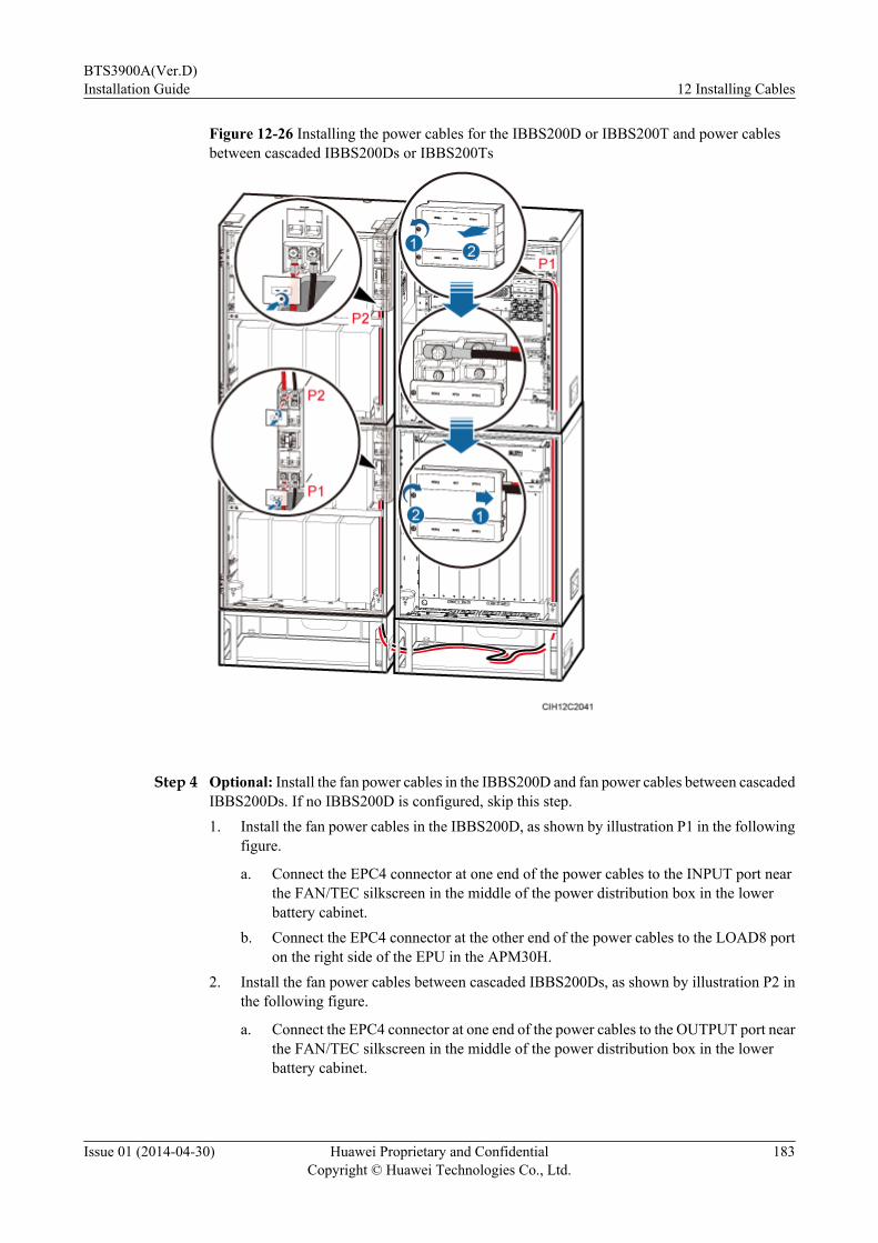
Figure 12-26 Installing the power cables for the IBBS200D or IBBS200T and power cablesbetween cascaded IBBS200Ds or IBBS200Ts
Step 4 Optional: Install the fan power cables in the IBBS200D and fan power cables between cascadedIBBS200Ds. If no IBBS200D is configured, skip this step.1. Install the fan power cables in the IBBS200D, as shown by illustration P1 in the following
figure.
a. Connect the EPC4 connector at one end of the power cables to the INPUT port nearthe FAN/TEC silkscreen in the middle of the power distribution box in the lowerbattery cabinet.
b. Connect the EPC4 connector at the other end of the power cables to the LOAD8 porton the right side of the EPU in the APM30H.
2. Install the fan power cables between cascaded IBBS200Ds, as shown by illustration P2 inthe following figure.
a. Connect the EPC4 connector at one end of the power cables to the OUTPUT port nearthe FAN/TEC silkscreen in the middle of the power distribution box in the lowerbattery cabinet.
BTS3900A(Ver.D)Installation Guide 12 Installing Cables
Issue 01 (2014-04-30) Huawei Proprietary and ConfidentialCopyright © Huawei Technologies Co., Ltd.
183
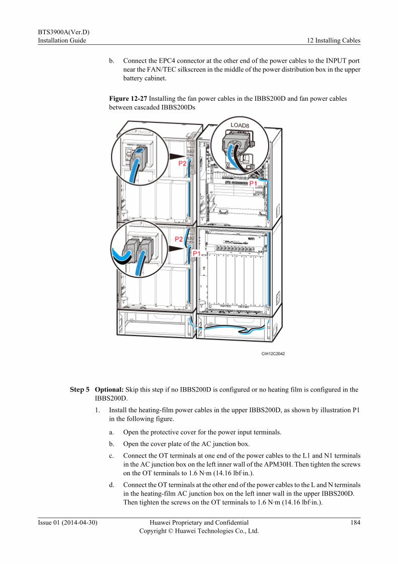
b. Connect the EPC4 connector at the other end of the power cables to the INPUT portnear the FAN/TEC silkscreen in the middle of the power distribution box in the upperbattery cabinet.
Figure 12-27 Installing the fan power cables in the IBBS200D and fan power cablesbetween cascaded IBBS200Ds
Step 5 Optional: Skip this step if no IBBS200D is configured or no heating film is configured in theIBBS200D.
1. Install the heating-film power cables in the upper IBBS200D, as shown by illustration P1in the following figure.
a. Open the protective cover for the power input terminals.
b. Open the cover plate of the AC junction box.
c. Connect the OT terminals at one end of the power cables to the L1 and N1 terminalsin the AC junction box on the left inner wall of the APM30H. Then tighten the screwson the OT terminals to 1.6 N·m (14.16 lbf·in.).
d. Connect the OT terminals at the other end of the power cables to the L and N terminalsin the heating-film AC junction box on the left inner wall in the upper IBBS200D.Then tighten the screws on the OT terminals to 1.6 N·m (14.16 lbf·in.).
BTS3900A(Ver.D)Installation Guide 12 Installing Cables
Issue 01 (2014-04-30) Huawei Proprietary and ConfidentialCopyright © Huawei Technologies Co., Ltd.
184
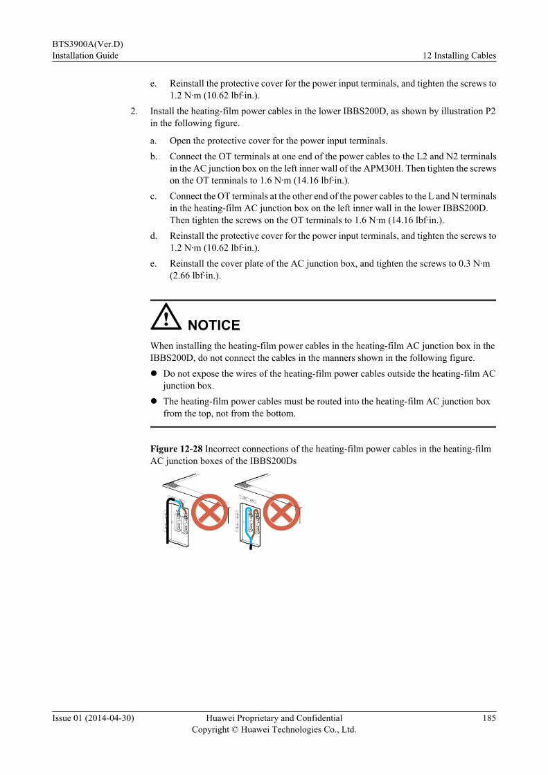
e. Reinstall the protective cover for the power input terminals, and tighten the screws to1.2 N·m (10.62 lbf·in.).
2. Install the heating-film power cables in the lower IBBS200D, as shown by illustration P2in the following figure.
a. Open the protective cover for the power input terminals.b. Connect the OT terminals at one end of the power cables to the L2 and N2 terminals
in the AC junction box on the left inner wall of the APM30H. Then tighten the screwson the OT terminals to 1.6 N·m (14.16 lbf·in.).
c. Connect the OT terminals at the other end of the power cables to the L and N terminalsin the heating-film AC junction box on the left inner wall in the lower IBBS200D.Then tighten the screws on the OT terminals to 1.6 N·m (14.16 lbf·in.).
d. Reinstall the protective cover for the power input terminals, and tighten the screws to1.2 N·m (10.62 lbf·in.).
e. Reinstall the cover plate of the AC junction box, and tighten the screws to 0.3 N·m(2.66 lbf·in.).
NOTICEWhen installing the heating-film power cables in the heating-film AC junction box in theIBBS200D, do not connect the cables in the manners shown in the following figure.l Do not expose the wires of the heating-film power cables outside the heating-film AC
junction box.l The heating-film power cables must be routed into the heating-film AC junction box
from the top, not from the bottom.
Figure 12-28 Incorrect connections of the heating-film power cables in the heating-filmAC junction boxes of the IBBS200Ds
BTS3900A(Ver.D)Installation Guide 12 Installing Cables
Issue 01 (2014-04-30) Huawei Proprietary and ConfidentialCopyright © Huawei Technologies Co., Ltd.
185
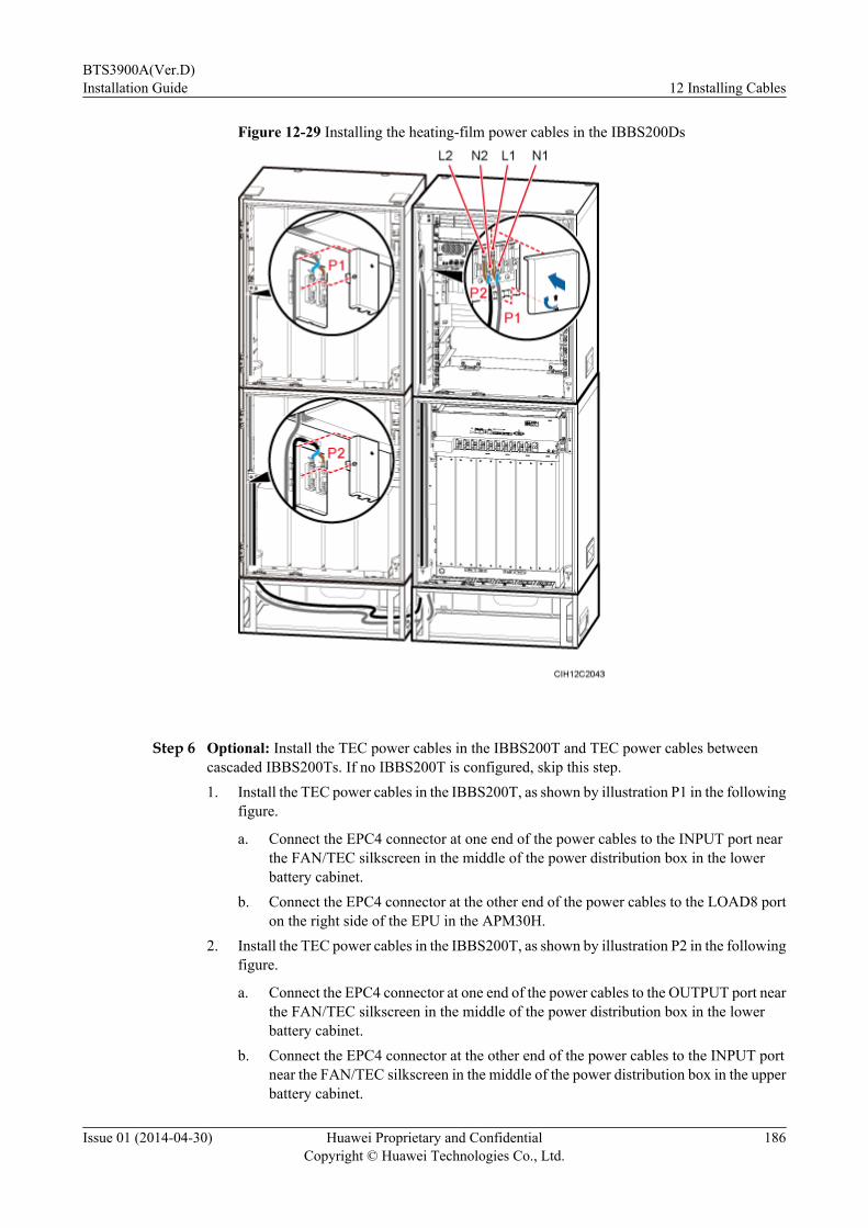
Figure 12-29 Installing the heating-film power cables in the IBBS200Ds
Step 6 Optional: Install the TEC power cables in the IBBS200T and TEC power cables betweencascaded IBBS200Ts. If no IBBS200T is configured, skip this step.1. Install the TEC power cables in the IBBS200T, as shown by illustration P1 in the following
figure.
a. Connect the EPC4 connector at one end of the power cables to the INPUT port nearthe FAN/TEC silkscreen in the middle of the power distribution box in the lowerbattery cabinet.
b. Connect the EPC4 connector at the other end of the power cables to the LOAD8 porton the right side of the EPU in the APM30H.
2. Install the TEC power cables in the IBBS200T, as shown by illustration P2 in the followingfigure.
a. Connect the EPC4 connector at one end of the power cables to the OUTPUT port nearthe FAN/TEC silkscreen in the middle of the power distribution box in the lowerbattery cabinet.
b. Connect the EPC4 connector at the other end of the power cables to the INPUT portnear the FAN/TEC silkscreen in the middle of the power distribution box in the upperbattery cabinet.
BTS3900A(Ver.D)Installation Guide 12 Installing Cables
Issue 01 (2014-04-30) Huawei Proprietary and ConfidentialCopyright © Huawei Technologies Co., Ltd.
186
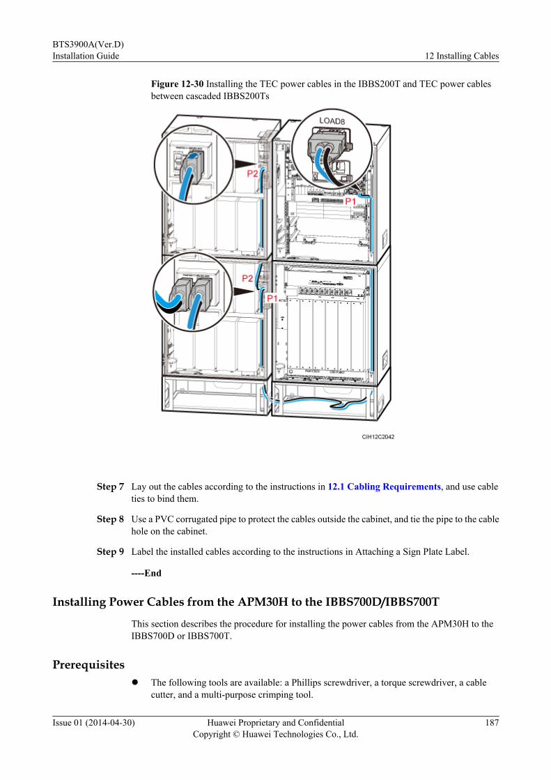
Figure 12-30 Installing the TEC power cables in the IBBS200T and TEC power cablesbetween cascaded IBBS200Ts
Step 7 Lay out the cables according to the instructions in 12.1 Cabling Requirements, and use cableties to bind them.
Step 8 Use a PVC corrugated pipe to protect the cables outside the cabinet, and tie the pipe to the cablehole on the cabinet.
Step 9 Label the installed cables according to the instructions in Attaching a Sign Plate Label.
----End
Installing Power Cables from the APM30H to the IBBS700D/IBBS700T
This section describes the procedure for installing the power cables from the APM30H to theIBBS700D or IBBS700T.
Prerequisitesl The following tools are available: a Phillips screwdriver, a torque screwdriver, a cable
cutter, and a multi-purpose crimping tool.
BTS3900A(Ver.D)Installation Guide 12 Installing Cables
Issue 01 (2014-04-30) Huawei Proprietary and ConfidentialCopyright © Huawei Technologies Co., Ltd.
187
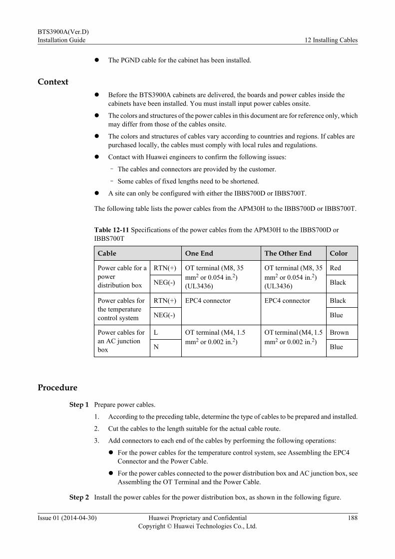
l The PGND cable for the cabinet has been installed.
Contextl Before the BTS3900A cabinets are delivered, the boards and power cables inside the
cabinets have been installed. You must install input power cables onsite.
l The colors and structures of the power cables in this document are for reference only, whichmay differ from those of the cables onsite.
l The colors and structures of cables vary according to countries and regions. If cables arepurchased locally, the cables must comply with local rules and regulations.
l Contact with Huawei engineers to confirm the following issues:
– The cables and connectors are provided by the customer.
– Some cables of fixed lengths need to be shortened.
l A site can only be configured with either the IBBS700D or IBBS700T.
The following table lists the power cables from the APM30H to the IBBS700D or IBBS700T.
Table 12-11 Specifications of the power cables from the APM30H to the IBBS700D orIBBS700T
Cable One End The Other End Color
Power cable for apowerdistribution box
RTN(+) OT terminal (M8, 35mm2 or 0.054 in.2)(UL3436)
OT terminal (M8, 35mm2 or 0.054 in.2)(UL3436)
Red
NEG(-) Black
Power cables forthe temperaturecontrol system
RTN(+) EPC4 connector EPC4 connector Black
NEG(-) Blue
Power cables foran AC junctionbox
L OT terminal (M4, 1.5mm2 or 0.002 in.2)
OT terminal (M4, 1.5mm2 or 0.002 in.2)
Brown
N Blue
Procedure
Step 1 Prepare power cables.
1. According to the preceding table, determine the type of cables to be prepared and installed.
2. Cut the cables to the length suitable for the actual cable route.
3. Add connectors to each end of the cables by performing the following operations:
l For the power cables for the temperature control system, see Assembling the EPC4Connector and the Power Cable.
l For the power cables connected to the power distribution box and AC junction box, seeAssembling the OT Terminal and the Power Cable.
Step 2 Install the power cables for the power distribution box, as shown in the following figure.
BTS3900A(Ver.D)Installation Guide 12 Installing Cables
Issue 01 (2014-04-30) Huawei Proprietary and ConfidentialCopyright © Huawei Technologies Co., Ltd.
188
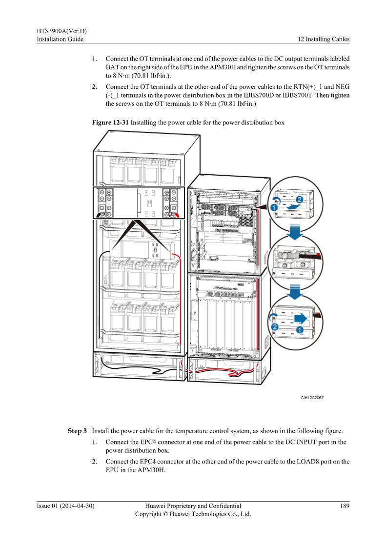
1. Connect the OT terminals at one end of the power cables to the DC output terminals labeledBAT on the right side of the EPU in the APM30H and tighten the screws on the OT terminalsto 8 N·m (70.81 lbf·in.).
2. Connect the OT terminals at the other end of the power cables to the RTN(+)_1 and NEG(-)_1 terminals in the power distribution box in the IBBS700D or IBBS700T. Then tightenthe screws on the OT terminals to 8 N·m (70.81 lbf·in.).
Figure 12-31 Installing the power cable for the power distribution box
Step 3 Install the power cable for the temperature control system, as shown in the following figure.1. Connect the EPC4 connector at one end of the power cable to the DC INPUT port in the
power distribution box.2. Connect the EPC4 connector at the other end of the power cable to the LOAD8 port on the
EPU in the APM30H.
BTS3900A(Ver.D)Installation Guide 12 Installing Cables
Issue 01 (2014-04-30) Huawei Proprietary and ConfidentialCopyright © Huawei Technologies Co., Ltd.
189
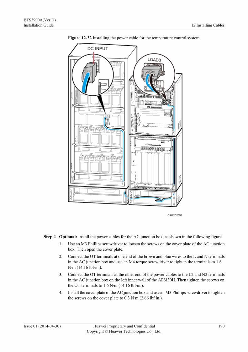
Figure 12-32 Installing the power cable for the temperature control system
Step 4 Optional: Install the power cables for the AC junction box, as shown in the following figure.1. Use an M3 Phillips screwdriver to loosen the screws on the cover plate of the AC junction
box. Then open the cover plate.2. Connect the OT terminals at one end of the brown and blue wires to the L and N terminals
in the AC junction box and use an M4 torque screwdriver to tighten the terminals to 1.6N·m (14.16 lbf·in.).
3. Connect the OT terminals at the other end of the power cables to the L2 and N2 terminalsin the AC junction box on the left inner wall of the APM30H. Then tighten the screws onthe OT terminals to 1.6 N·m (14.16 lbf·in.).
4. Install the cover plate of the AC junction box and use an M3 Phillips screwdriver to tightenthe screws on the cover plate to 0.3 N·m (2.66 lbf·in.).
BTS3900A(Ver.D)Installation Guide 12 Installing Cables
Issue 01 (2014-04-30) Huawei Proprietary and ConfidentialCopyright © Huawei Technologies Co., Ltd.
190
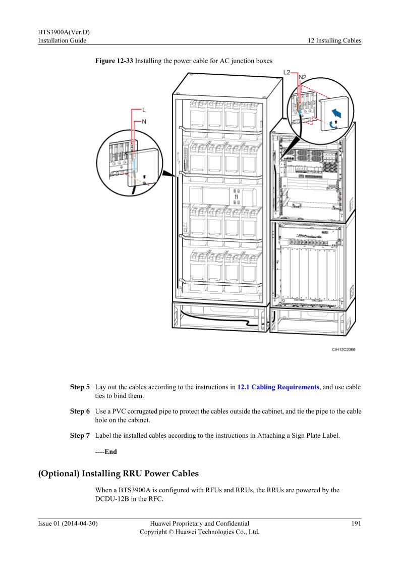
Figure 12-33 Installing the power cable for AC junction boxes
Step 5 Lay out the cables according to the instructions in 12.1 Cabling Requirements, and use cableties to bind them.
Step 6 Use a PVC corrugated pipe to protect the cables outside the cabinet, and tie the pipe to the cablehole on the cabinet.
Step 7 Label the installed cables according to the instructions in Attaching a Sign Plate Label.
----End
(Optional) Installing RRU Power Cables
When a BTS3900A is configured with RFUs and RRUs, the RRUs are powered by theDCDU-12B in the RFC.
BTS3900A(Ver.D)Installation Guide 12 Installing Cables
Issue 01 (2014-04-30) Huawei Proprietary and ConfidentialCopyright © Huawei Technologies Co., Ltd.
191

Prerequisitesl The following tools are available: a Phillips screwdriver, a torque screwdriver, a cable
cutter, and a multi-purpose crimping tool.
l The PGND cable for the cabinet has been installed.
Contextl Before the BTS3900A cabinets are delivered, the boards and power cables inside the
cabinets have been installed. You must install input power cables onsite.
l The colors and structures of the power cables in this document are for reference only, whichmay differ from those of the cables onsite.
l The colors and structures of cables vary according to countries and regions. If cables arepurchased locally, the cables must comply with local rules and regulations.
l Contact with Huawei engineers to confirm the following issues:
– The cables and connectors are provided by the customer.
– Some cables of fixed lengths need to be shortened.
l The type of connector connecting to the power port on the RRU depends on the type of theRRU. For details about how to add a connector to an RRU power cable, see the relatedRRU installation guide.
The following table lists the specifications of an RRU power cable when the DCDU-12B suppliespower.
Table 12-12 Specifications of an RRU power cable
Cable Wire Color One End The OtherEnd
NorthAmericanStandard
EuropeanStandard
RRUpowercable
RTN(+)
Black Brown EPC5 or EPC4connector
Depending onthe port on theRRU
NEG(-)
Blue Blue
Procedure
Step 1 Route the RRU power cable through a cable bag into the cabinet.
Step 2 Install the ground clip, as shown in Figure 12-35.
1. Strip a length of jacket off the RRU power cable at the position 300 mm (11.81 in.) awayfrom the cable bag in the RFC to expose the shield layer.
2. Strip the shield layer to expose the two wires at the position 350 mm (13.78 in.) away fromthe cable bag in the RFC.
BTS3900A(Ver.D)Installation Guide 12 Installing Cables
Issue 01 (2014-04-30) Huawei Proprietary and ConfidentialCopyright © Huawei Technologies Co., Ltd.
192
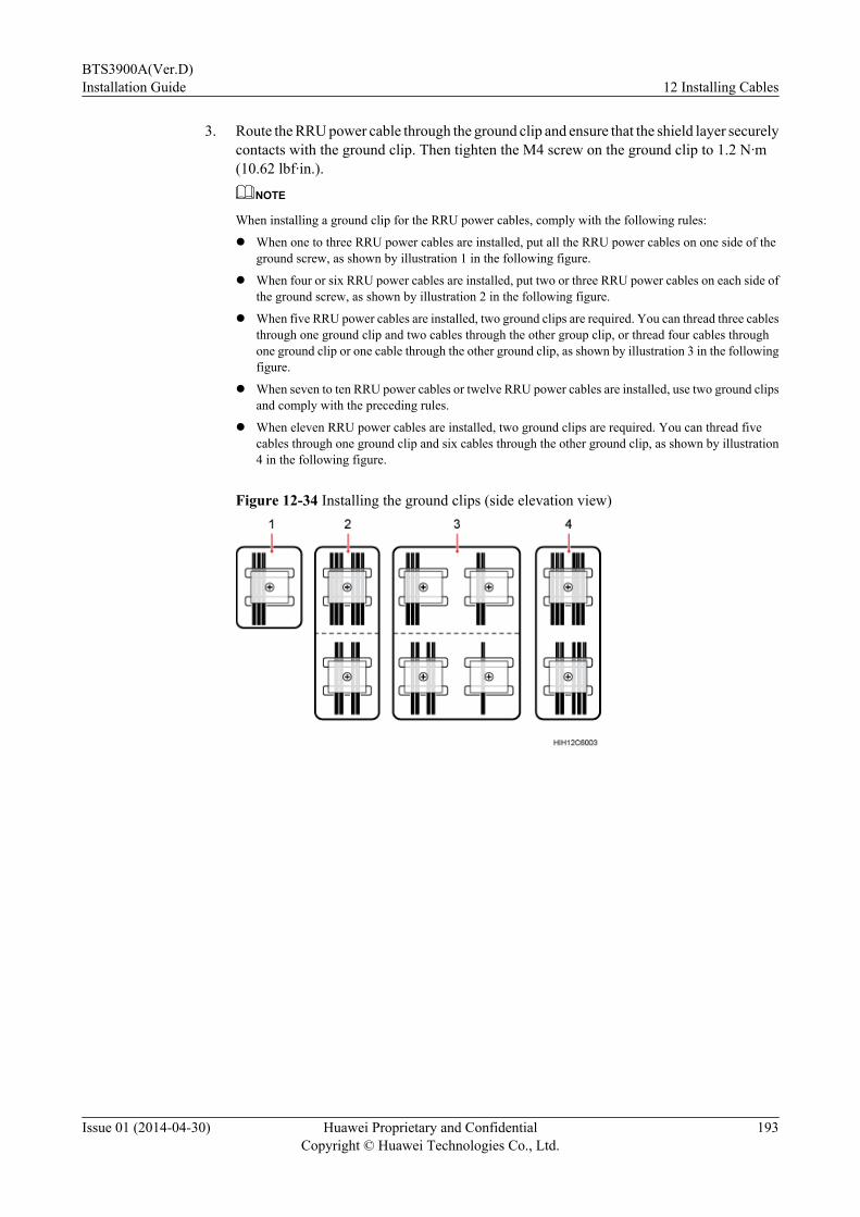
3. Route the RRU power cable through the ground clip and ensure that the shield layer securelycontacts with the ground clip. Then tighten the M4 screw on the ground clip to 1.2 N·m(10.62 lbf·in.).
NOTE
When installing a ground clip for the RRU power cables, comply with the following rules:
l When one to three RRU power cables are installed, put all the RRU power cables on one side of theground screw, as shown by illustration 1 in the following figure.
l When four or six RRU power cables are installed, put two or three RRU power cables on each side ofthe ground screw, as shown by illustration 2 in the following figure.
l When five RRU power cables are installed, two ground clips are required. You can thread three cablesthrough one ground clip and two cables through the other group clip, or thread four cables throughone ground clip or one cable through the other ground clip, as shown by illustration 3 in the followingfigure.
l When seven to ten RRU power cables or twelve RRU power cables are installed, use two ground clipsand comply with the preceding rules.
l When eleven RRU power cables are installed, two ground clips are required. You can thread fivecables through one ground clip and six cables through the other ground clip, as shown by illustration4 in the following figure.
Figure 12-34 Installing the ground clips (side elevation view)
BTS3900A(Ver.D)Installation Guide 12 Installing Cables
Issue 01 (2014-04-30) Huawei Proprietary and ConfidentialCopyright © Huawei Technologies Co., Ltd.
193

Figure 12-35 Installing the ground clip
Step 3 Add an EPC5 or EPC4 connector to the RRU power cable on the DCDU-12B side. For detailsabout how to add the connector, see Assembling the EPC5 Connector and the Power Cable orAssembling the EPC4 Connector and the Power Cable.
Step 4 Connect the connector at one end of the RRU power cable to the RRU.
Step 5 Connect the EPC5 or EPC4 connector at the other end of the RRU power cable to one of theLOAD0 to LOAD8 ports on the DCDU-12B, as shown in the following figure.
CAUTIONEnsure that the RRU power cable for an RRU added to a running base station must be connectedto the RRU first and then to the power equipment. The operations in the reverse sequence maycause component damage or personal injury.
BTS3900A(Ver.D)Installation Guide 12 Installing Cables
Issue 01 (2014-04-30) Huawei Proprietary and ConfidentialCopyright © Huawei Technologies Co., Ltd.
194
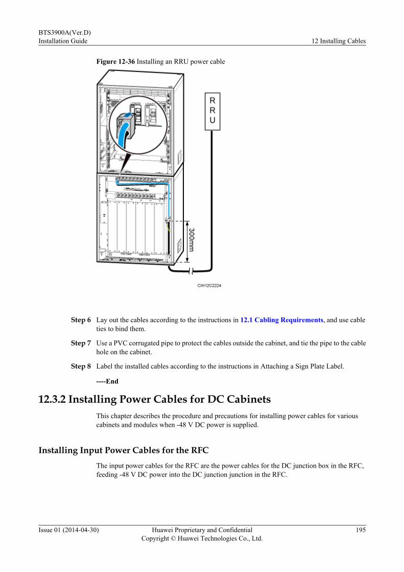
Figure 12-36 Installing an RRU power cable
Step 6 Lay out the cables according to the instructions in 12.1 Cabling Requirements, and use cableties to bind them.
Step 7 Use a PVC corrugated pipe to protect the cables outside the cabinet, and tie the pipe to the cablehole on the cabinet.
Step 8 Label the installed cables according to the instructions in Attaching a Sign Plate Label.
----End
12.3.2 Installing Power Cables for DC CabinetsThis chapter describes the procedure and precautions for installing power cables for variouscabinets and modules when -48 V DC power is supplied.
Installing Input Power Cables for the RFCThe input power cables for the RFC are the power cables for the DC junction box in the RFC,feeding -48 V DC power into the DC junction junction in the RFC.
BTS3900A(Ver.D)Installation Guide 12 Installing Cables
Issue 01 (2014-04-30) Huawei Proprietary and ConfidentialCopyright © Huawei Technologies Co., Ltd.
195
Prerequisitesl The following tools are available: a Phillips screwdriver, a torque screwdriver, a cable
cutter, and a multi-purpose crimping tool.
l The PGND cable for the cabinet has been installed.
l The external power supply to the RFC has been shut off.
Contextl The colors and structures of the power cables in this document are for reference only, which
may differ from those of the cables onsite.
l The colors and structures of cables vary according to countries and regions. If cables arepurchased locally, the cables must comply with local rules and regulations.
l Contact with Huawei engineers to confirm the following issues:
– The cables and connectors are provided by the customer.
– Some cables of fixed lengths need to be shortened.
The RFC supports two types of input power cables: 35 mm2 (0.054 in.2) and 16 mm2 (0.025 in.2), as listed in.Table 12-13.
Table 12-13 Specifications of the input power cables for the RFC
Cable One End TheOtherEnd
Color
Power cable forthe DC junctionbox
(35 mm2 or0.054 in.2, agroup)
RTN(+) OT terminal (M6, 35mm2 or 0.054 in.2)
Depending on theexternalequipment
Black
NEG(-) Blue
Power cable forthe DC junctionbox
(16 mm2 or0.025 in.2, twogroups)
RTN(+) OT terminal (M6, 16mm2 or 0.025 in.2)
Depending on theexternalequipment
Black
NEG(-) Blue
Procedure
Step 1 Install the power cables for the DC junction box.
1. Cut the cables to the length suitable for the actual cable route.
2. Install a corresponding connector at each end of the input power cables for the RFCaccording to the specifications in the preceding table and the instructions in Assemblingthe OT Terminal and the Power Cable.
BTS3900A(Ver.D)Installation Guide 12 Installing Cables
Issue 01 (2014-04-30) Huawei Proprietary and ConfidentialCopyright © Huawei Technologies Co., Ltd.
196

Step 2 Install the power cables for the DC junction box, as shown in the following figure.
1. Connect the OT terminals at one end of the power cables to the RTN(+) and NEG(-)terminals in the DC junction box on an inner wall of the RFC.
2. Connect the OT terminals at the other end of the power cables to the external powerequipment.
Figure 12-37 Installing the power cables for the DC junction box
Step 3 Lay out the cables according to the instructions in 12.1 Cabling Requirements, and use cableties to bind them.
Step 4 Use a PVC corrugated pipe to protect the cables outside the cabinet, and tie the pipe to the cablehole on the cabinet.
Step 5 Label the installed cables according to the instructions in Attaching a Sign Plate Label.
----End
(Optional) Installing RRU Power Cables
When a BTS3900A is configured with RFUs and RRUs, the RRUs are powered by theDCDU-12B in the RFC.
BTS3900A(Ver.D)Installation Guide 12 Installing Cables
Issue 01 (2014-04-30) Huawei Proprietary and ConfidentialCopyright © Huawei Technologies Co., Ltd.
197
Prerequisitesl The following tools are available: a Phillips screwdriver, a torque screwdriver, a cable
cutter, and a multi-purpose crimping tool.
l The PGND cable for the cabinet has been installed.
Contextl Before the BTS3900A cabinets are delivered, the boards and power cables inside the
cabinets have been installed. You must install input power cables onsite.
l The colors and structures of the power cables in this document are for reference only, whichmay differ from those of the cables onsite.
l The colors and structures of cables vary according to countries and regions. If cables arepurchased locally, the cables must comply with local rules and regulations.
l Contact with Huawei engineers to confirm the following issues:
– The cables and connectors are provided by the customer.
– Some cables of fixed lengths need to be shortened.
l The type of connector connecting to the power port on the RRU depends on the type of theRRU. For details about how to add a connector to an RRU power cable, see the relatedRRU installation guide.
The following table lists the specifications of an RRU power cable when the DCDU-12B suppliespower.
Table 12-14 Specifications of an RRU power cable
Cable Wire Color One End The OtherEnd
NorthAmericanStandard
EuropeanStandard
RRUpowercable
RTN(+)
Black Brown EPC5 or EPC4connector
Depending onthe port on theRRU
NEG(-)
Blue Blue
Procedure
Step 1 Route the RRU power cable through a cable bag into the cabinet.
Step 2 Install the ground clip, as shown in Figure 12-39.
1. Strip a length of jacket off the RRU power cable at the position 300 mm (11.81 in.) awayfrom the cable bag in the RFC to expose the shield layer.
2. Strip the shield layer to expose the two wires at the position 350 mm (13.78 in.) away fromthe cable bag in the RFC.
BTS3900A(Ver.D)Installation Guide 12 Installing Cables
Issue 01 (2014-04-30) Huawei Proprietary and ConfidentialCopyright © Huawei Technologies Co., Ltd.
198
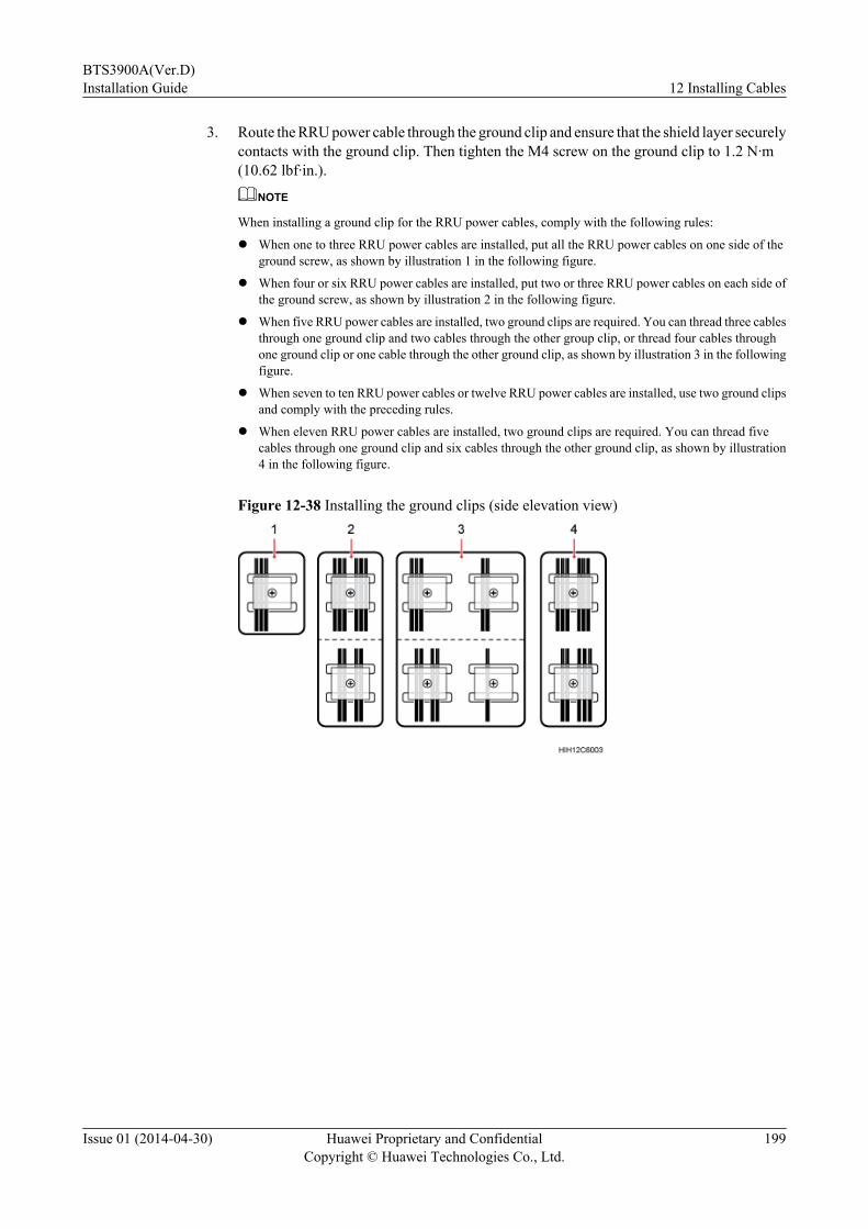
3. Route the RRU power cable through the ground clip and ensure that the shield layer securelycontacts with the ground clip. Then tighten the M4 screw on the ground clip to 1.2 N·m(10.62 lbf·in.).
NOTE
When installing a ground clip for the RRU power cables, comply with the following rules:
l When one to three RRU power cables are installed, put all the RRU power cables on one side of theground screw, as shown by illustration 1 in the following figure.
l When four or six RRU power cables are installed, put two or three RRU power cables on each side ofthe ground screw, as shown by illustration 2 in the following figure.
l When five RRU power cables are installed, two ground clips are required. You can thread three cablesthrough one ground clip and two cables through the other group clip, or thread four cables throughone ground clip or one cable through the other ground clip, as shown by illustration 3 in the followingfigure.
l When seven to ten RRU power cables or twelve RRU power cables are installed, use two ground clipsand comply with the preceding rules.
l When eleven RRU power cables are installed, two ground clips are required. You can thread fivecables through one ground clip and six cables through the other ground clip, as shown by illustration4 in the following figure.
Figure 12-38 Installing the ground clips (side elevation view)
BTS3900A(Ver.D)Installation Guide 12 Installing Cables
Issue 01 (2014-04-30) Huawei Proprietary and ConfidentialCopyright © Huawei Technologies Co., Ltd.
199
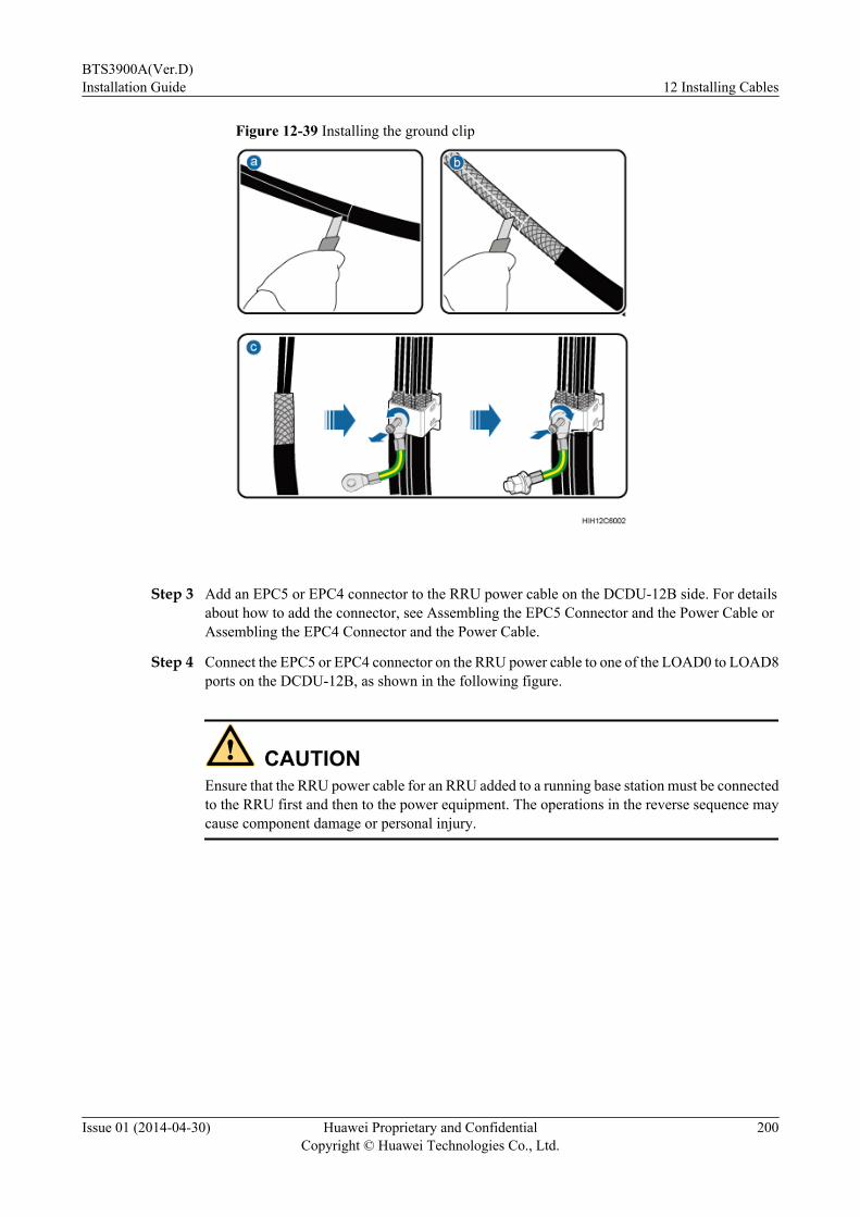
Figure 12-39 Installing the ground clip
Step 3 Add an EPC5 or EPC4 connector to the RRU power cable on the DCDU-12B side. For detailsabout how to add the connector, see Assembling the EPC5 Connector and the Power Cable orAssembling the EPC4 Connector and the Power Cable.
Step 4 Connect the EPC5 or EPC4 connector on the RRU power cable to one of the LOAD0 to LOAD8ports on the DCDU-12B, as shown in the following figure.
CAUTIONEnsure that the RRU power cable for an RRU added to a running base station must be connectedto the RRU first and then to the power equipment. The operations in the reverse sequence maycause component damage or personal injury.
BTS3900A(Ver.D)Installation Guide 12 Installing Cables
Issue 01 (2014-04-30) Huawei Proprietary and ConfidentialCopyright © Huawei Technologies Co., Ltd.
200

Figure 12-40 Installing an RRU power cable
Step 5 Lay out the cables according to the instructions in 12.1 Cabling Requirements, and use cableties to bind them.
Step 6 Use a PVC corrugated pipe to protect the cables outside the cabinet, and tie the pipe to the cablehole on the cabinet.
Step 7 Label the installed cables according to the instructions in Attaching a Sign Plate Label.
----End
12.4 Installing Transmission CablesThis chapter describes the procedures and precautions for installing transmission cables betweenthe cabinet and external transmission equipment.
12.4.1 Installing the E1/T1 CablesThis section describes the procedure and precautions for installing the E1/T1 cables.
BTS3900A(Ver.D)Installation Guide 12 Installing Cables
Issue 01 (2014-04-30) Huawei Proprietary and ConfidentialCopyright © Huawei Technologies Co., Ltd.
201

Prerequisites
NOTICEEnsure that both ends of the E1/T1 cable are disconnected from any equipment. Then, solder aconnector to each E1/T1 cable during the same session.
Contextl Contact Huawei engineers to confirm the following issues:
– The cables and connectors prepared by the customer will be used.
– Some cables of fixed lengths need to be shortened.l When the TMC11H uses the -48 V DC power supply, the connections and routing of the
E1/T1 cables in this cabinet are the same as those in the APM30H shown in Figure12-41.
l This section describes the connections and routing of E1/T1 cables for a BTS3900A(Ver.D). The connections and routing of E1/T1 cables for the BTS3900A (Ver.B),BTS3900A (Ver.C), and BTS3900A (Ver.D) are the same.
Procedure
Step 1 Connect one end of the E1/T1 cables to the OUTSIDE ports on the UELP, as shown in thefollowing figure.
NOTE
For details about the connections of E1/T1 cables, see section "Transmission Cable Connections" in the 3900Series Base Station Cables.
BTS3900A(Ver.D)Installation Guide 12 Installing Cables
Issue 01 (2014-04-30) Huawei Proprietary and ConfidentialCopyright © Huawei Technologies Co., Ltd.
202
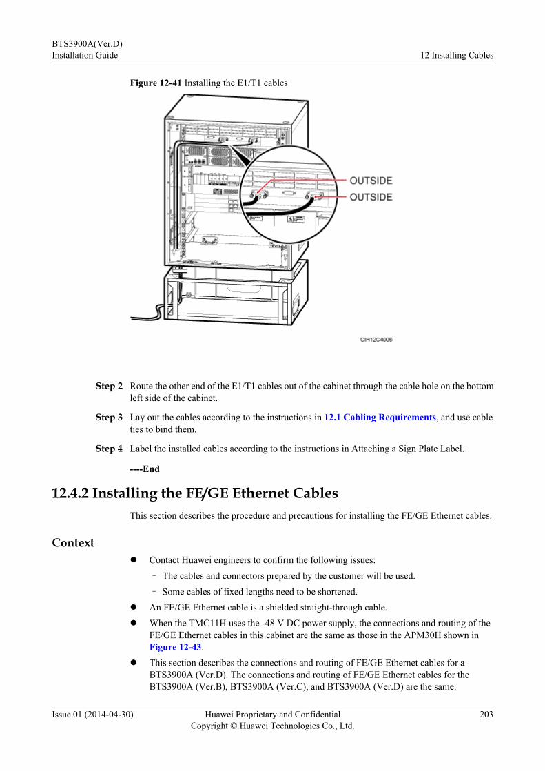
Figure 12-41 Installing the E1/T1 cables
Step 2 Route the other end of the E1/T1 cables out of the cabinet through the cable hole on the bottomleft side of the cabinet.
Step 3 Lay out the cables according to the instructions in 12.1 Cabling Requirements, and use cableties to bind them.
Step 4 Label the installed cables according to the instructions in Attaching a Sign Plate Label.
----End
12.4.2 Installing the FE/GE Ethernet CablesThis section describes the procedure and precautions for installing the FE/GE Ethernet cables.
Contextl Contact Huawei engineers to confirm the following issues:
– The cables and connectors prepared by the customer will be used.
– Some cables of fixed lengths need to be shortened.l An FE/GE Ethernet cable is a shielded straight-through cable.l When the TMC11H uses the -48 V DC power supply, the connections and routing of the
FE/GE Ethernet cables in this cabinet are the same as those in the APM30H shown inFigure 12-43.
l This section describes the connections and routing of FE/GE Ethernet cables for aBTS3900A (Ver.D). The connections and routing of FE/GE Ethernet cables for theBTS3900A (Ver.B), BTS3900A (Ver.C), and BTS3900A (Ver.D) are the same.
BTS3900A(Ver.D)Installation Guide 12 Installing Cables
Issue 01 (2014-04-30) Huawei Proprietary and ConfidentialCopyright © Huawei Technologies Co., Ltd.
203

Procedure
Step 1 Route the FE/GE Ethernet cables through a cable bag or a cable outlet module into the cabinet.
Step 2 Install a ground clip for the FE/GE Ethernet cables in a proper position within 1 m (3.28 ft.)from the cable hole of the cabinet, as shown in the following figure.1. Determine the position for grounding the FE/GE Ethernet cables, and strip the sheath off
the cables for about 40 mm (1.57 in.) to expose the shield layer.2. Loosen the screws on the ground clip, and route the FE/GE cables through the clip.3. Attach a ground clip to the shield layer of the FE/GE Ethernet cables and tighten the M4
screws on the ground clip to 1.2 N·m (10.62 lbf·in.).
Figure 12-42 Installing the ground clip
Step 3 Connect one end of the FE/GE Ethernet cables to the FE0 (or FE/GE0) or FE1 (or FE/GE1) portsnear the OUTSIDE silkscreen on the UFLP, as shown in the following figure.
NOTE
For details about the connections of FE/GE Ethernet cables, see section "Transmission Cable Connections" inthe 3900 Series Base Station Cables.
BTS3900A(Ver.D)Installation Guide 12 Installing Cables
Issue 01 (2014-04-30) Huawei Proprietary and ConfidentialCopyright © Huawei Technologies Co., Ltd.
204

Figure 12-43 Installing the FE/GE Ethernet cables
Step 4 Lay out the cables according to the instructions in 12.1 Cabling Requirements, and use cableties to bind them.
Step 5 Label the installed cables according to the instructions in Attaching a Sign Plate Label.
----End
12.4.3 Installing the FE/GE Fiber Optic CablesThis section describes the procedure and precautions for installing the FE/GE fiber optic cables.
Contextl Contact Huawei engineers to confirm the following issues:
– The cables and connectors prepared by the customer will be used.
– Some cables of fixed lengths need to be shortened.
l Single-mode optical modules are labeled as SM and multimode optical modules are labeledas MM.
l The puller of a single-mode optical module is blue. The puller of a multimode opticalmodule is black or gray.
l The optical modules to be installed must match the rates of their corresponding ports.
l An FE/GE fiber optic cable has an LC connector at one end and an FC connector, SCconnector, or LC connector at the other end.
BTS3900A(Ver.D)Installation Guide 12 Installing Cables
Issue 01 (2014-04-30) Huawei Proprietary and ConfidentialCopyright © Huawei Technologies Co., Ltd.
205
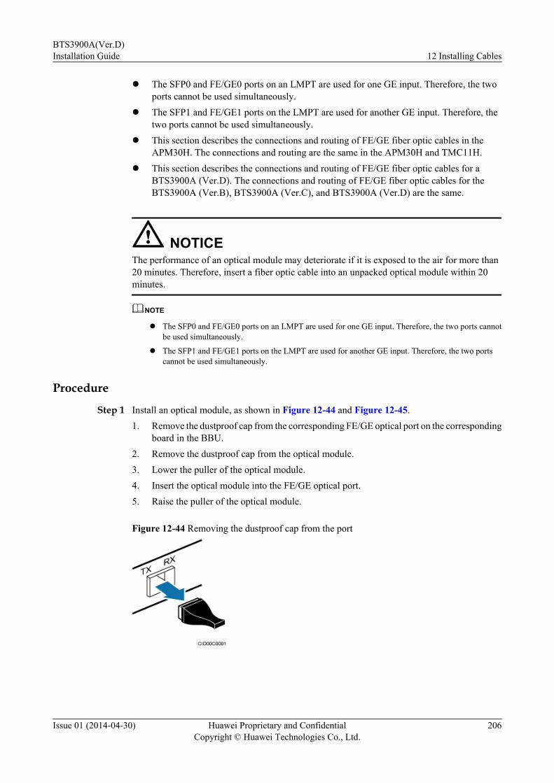
l The SFP0 and FE/GE0 ports on an LMPT are used for one GE input. Therefore, the twoports cannot be used simultaneously.
l The SFP1 and FE/GE1 ports on the LMPT are used for another GE input. Therefore, thetwo ports cannot be used simultaneously.
l This section describes the connections and routing of FE/GE fiber optic cables in theAPM30H. The connections and routing are the same in the APM30H and TMC11H.
l This section describes the connections and routing of FE/GE fiber optic cables for aBTS3900A (Ver.D). The connections and routing of FE/GE fiber optic cables for theBTS3900A (Ver.B), BTS3900A (Ver.C), and BTS3900A (Ver.D) are the same.
NOTICEThe performance of an optical module may deteriorate if it is exposed to the air for more than20 minutes. Therefore, insert a fiber optic cable into an unpacked optical module within 20minutes.
NOTE
l The SFP0 and FE/GE0 ports on an LMPT are used for one GE input. Therefore, the two ports cannotbe used simultaneously.
l The SFP1 and FE/GE1 ports on the LMPT are used for another GE input. Therefore, the two portscannot be used simultaneously.
Procedure
Step 1 Install an optical module, as shown in Figure 12-44 and Figure 12-45.1. Remove the dustproof cap from the corresponding FE/GE optical port on the corresponding
board in the BBU.2. Remove the dustproof cap from the optical module.3. Lower the puller of the optical module.4. Insert the optical module into the FE/GE optical port.5. Raise the puller of the optical module.
Figure 12-44 Removing the dustproof cap from the port
BTS3900A(Ver.D)Installation Guide 12 Installing Cables
Issue 01 (2014-04-30) Huawei Proprietary and ConfidentialCopyright © Huawei Technologies Co., Ltd.
206

Figure 12-45 Installing the optical module
Step 2 Connect one end of the FE/GE fiber optic cables to the optical module, as shown in the followingfigure.
NOTE
For details about the connections of FE/GE fiber optic cables, see section "Transmission Cable Connections"in the 3900 Series Base Station Cables.
Figure 12-46 Installing FE/GE fiber optic cables
Step 3 Route the other end of the FE/GE fiber optic cables out of the cabinet through the cable hole onthe bottom right side of the cabinet.
Step 4 Lay out the cables according to the instructions in 12.1 Cabling Requirements, and use cableties to bind them.
Step 5 Label the installed cables according to the instructions in Attaching a Sign Plate Label.
----End
12.5 Installing Signal CablesThis chapter describes the procedures and precautions for installing the signal cables.
BTS3900A(Ver.D)Installation Guide 12 Installing Cables
Issue 01 (2014-04-30) Huawei Proprietary and ConfidentialCopyright © Huawei Technologies Co., Ltd.
207
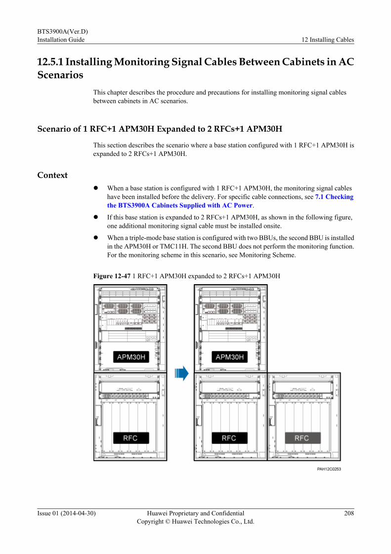
12.5.1 Installing Monitoring Signal Cables Between Cabinets in ACScenarios
This chapter describes the procedure and precautions for installing monitoring signal cablesbetween cabinets in AC scenarios.
Scenario of 1 RFC+1 APM30H Expanded to 2 RFCs+1 APM30H
This section describes the scenario where a base station configured with 1 RFC+1 APM30H isexpanded to 2 RFCs+1 APM30H.
Contextl When a base station is configured with 1 RFC+1 APM30H, the monitoring signal cables
have been installed before the delivery. For specific cable connections, see 7.1 Checkingthe BTS3900A Cabinets Supplied with AC Power.
l If this base station is expanded to 2 RFCs+1 APM30H, as shown in the following figure,one additional monitoring signal cable must be installed onsite.
l When a triple-mode base station is configured with two BBUs, the second BBU is installedin the APM30H or TMC11H. The second BBU does not perform the monitoring function.For the monitoring scheme in this scenario, see Monitoring Scheme.
Figure 12-47 1 RFC+1 APM30H expanded to 2 RFCs+1 APM30H
BTS3900A(Ver.D)Installation Guide 12 Installing Cables
Issue 01 (2014-04-30) Huawei Proprietary and ConfidentialCopyright © Huawei Technologies Co., Ltd.
208

Procedure
Step 1 Install the cascading monitoring signal cable for the fan assemblies (from the original RFC tothe added RFC), as shown in the following figure.
1. Connect one end of the cable to the COM_OUT port on the CMUEA in the fan assemblyof the original RFC.
2. Connect the other end of the cable to the COM_IN port on the CMUEA in the fan assemblyof the added RFC.
Figure 12-48 Installing a monitoring signal cable in a base station configured with 2 RFCs+1APM30H
Step 2 Lay out the cables according to the instructions in 12.1 Cabling Requirements, and use cableties to bind them.
Step 3 Label the installed cables according to the instructions in Attaching an L-Shaped Label.
Step 4 Use a PVC corrugated pipe to protect the cables outside the cabinet, and tie the pipe to the cablehole on the cabinet.
----End
BTS3900A(Ver.D)Installation Guide 12 Installing Cables
Issue 01 (2014-04-30) Huawei Proprietary and ConfidentialCopyright © Huawei Technologies Co., Ltd.
209

Scenario of 1 RFC+1 APM30H+1 IBBS200D/IBBS200T Expanded to 2 RFCs+1APM30H+2 IBBS200Ds/IBBS200Ts
This section describes the scenario where a base station configured with 1 RFC+1 APM30H+1IBBS200D/IBBS200T is expanded to 2 RFCs+1 APM30H+2 IBBS200Ds/IBBS200Ts.
Contextl When a base station is configured with 1 RFC+1 APM30H+1 IBBS200D/IBBS200T, one
monitoring signal cable must be installed onsite to connect the IBBS200D/IBBS200T andthe APM30H.
l If this base station is expanded to 2 RFCs+1 APM30H+2 IBBS200Ds/IBBS200Ts, asshown in the following figure, two additional monitoring signal cables must be installedonsite.
l When a triple-mode base station is configured with two BBUs, the second BBU is installedin the APM30H or TMC11H. The second BBU does not perform the monitoring function.For the monitoring scheme in this scenario, see Monitoring Scheme.
Figure 12-49 1 RFC+1 APM30H+1 IBBS200D/IBBS200T expanded to 2 RFCs+1 APM30H+2 IBBS200Ds/IBBS200Ts
Procedure
Step 1 Install the monitoring signal cable for the battery cabinet (from the IBBS200D/IBBS200T to theAPM30H), as shown in the following figure.1. Connect one end of the cable to the COM_IN port on the CMUEA on the door of the
IBBS200D or IBBS200T.2. Connect the other end of the cable to the COM_485 port on the PMU in the APM30H.
BTS3900A(Ver.D)Installation Guide 12 Installing Cables
Issue 01 (2014-04-30) Huawei Proprietary and ConfidentialCopyright © Huawei Technologies Co., Ltd.
210
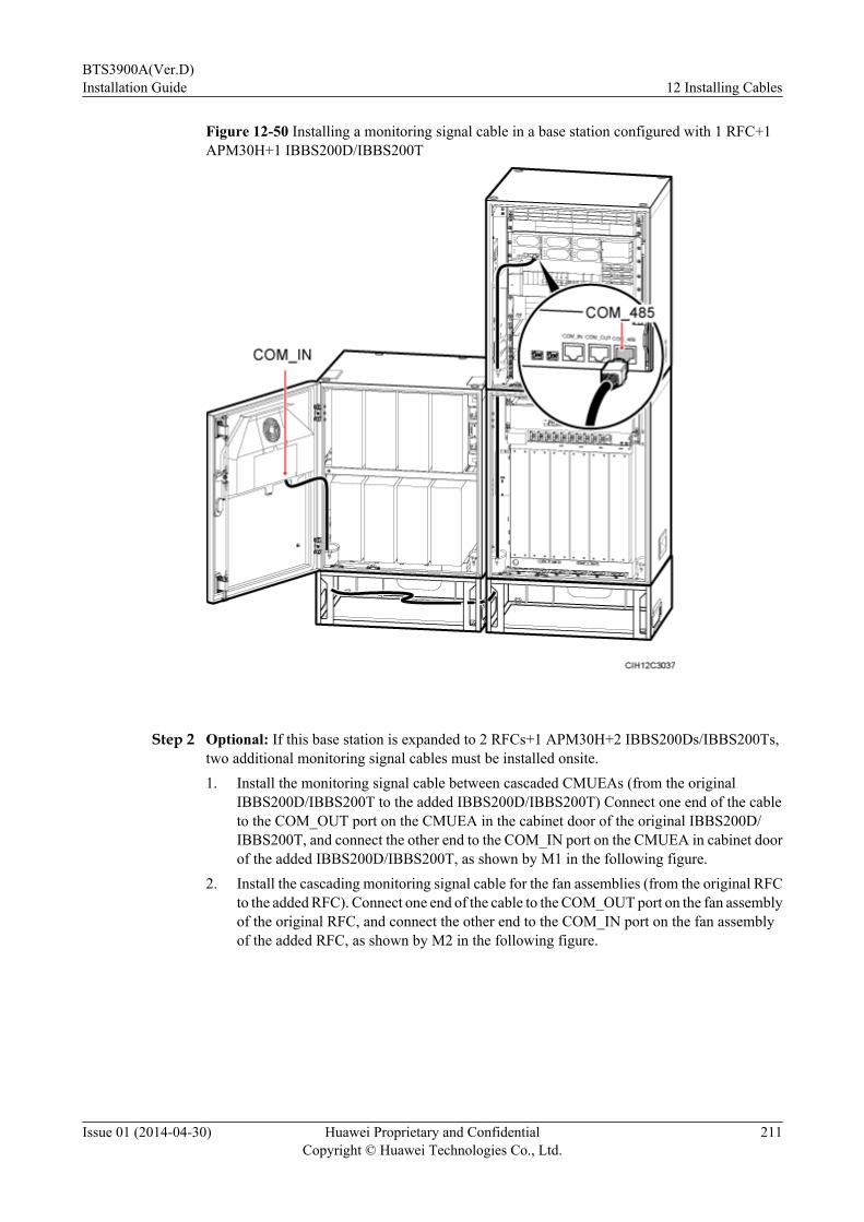
Figure 12-50 Installing a monitoring signal cable in a base station configured with 1 RFC+1APM30H+1 IBBS200D/IBBS200T
Step 2 Optional: If this base station is expanded to 2 RFCs+1 APM30H+2 IBBS200Ds/IBBS200Ts,two additional monitoring signal cables must be installed onsite.1. Install the monitoring signal cable between cascaded CMUEAs (from the original
IBBS200D/IBBS200T to the added IBBS200D/IBBS200T) Connect one end of the cableto the COM_OUT port on the CMUEA in the cabinet door of the original IBBS200D/IBBS200T, and connect the other end to the COM_IN port on the CMUEA in cabinet doorof the added IBBS200D/IBBS200T, as shown by M1 in the following figure.
2. Install the cascading monitoring signal cable for the fan assemblies (from the original RFCto the added RFC). Connect one end of the cable to the COM_OUT port on the fan assemblyof the original RFC, and connect the other end to the COM_IN port on the fan assemblyof the added RFC, as shown by M2 in the following figure.
BTS3900A(Ver.D)Installation Guide 12 Installing Cables
Issue 01 (2014-04-30) Huawei Proprietary and ConfidentialCopyright © Huawei Technologies Co., Ltd.
211

Figure 12-51 Installing the monitoring signal cables in a base station configured with 2 RFCs+1 APM30H+2 IBBS200Ds/IBBS200Ts
Step 3 Lay out the cables according to the instructions in 12.1 Cabling Requirements, and use cableties to bind them.
Step 4 Label the installed cables according to the instructions in Attaching an L-Shaped Label.
Step 5 Use a PVC corrugated pipe to protect the cables outside the cabinet, and tie the pipe to the cablehole on the cabinet.
----End
Scenario of 1 RFC+1 APM30H+1 TMC11H Expanded to 2 RFCs+1 APM30H+1TMC11H
This section describes the scenario where a base station configured with 1 RFC+1 APM30H+1TMC11H is expanded to 2 RFCs+1 APM30H+1 TMC11H.
Contextl When a base station is configured with 1 RFC+1 APM30H+1 TMC11H, one monitoring
signal cable must be installed onsite to connect the TMC11H and the RFC.
BTS3900A(Ver.D)Installation Guide 12 Installing Cables
Issue 01 (2014-04-30) Huawei Proprietary and ConfidentialCopyright © Huawei Technologies Co., Ltd.
212

l If this base station is expanded to 2 RFCs+1 APM30H+1 TMC11H, as shown in thefollowing figure, one additional monitoring signal cable must be installed onsite.
l When a triple-mode base station is configured with two BBUs, the second BBU is installedin the APM30H or TMC11H. The second BBU does not perform the monitoring function.For the monitoring scheme in this scenario, see Monitoring Scheme.
Figure 12-52 1 RFC+1 APM30H+1 TMC11H expanded to 2 RFCs+1 APM30H+1 TMC11H
Procedure
Step 1 Install the cascading monitoring signal cable for the fan assemblies (from the RFC to theTMC11H), as shown in the following figure.1. Connect one end of the cable to the COM_OUT port on the CMUEA in the fan assembly
of the RFC.2. Connect the other end of the cable to the COM_IN port on the CMUEA in the fan assembly
of the TMC11H.
BTS3900A(Ver.D)Installation Guide 12 Installing Cables
Issue 01 (2014-04-30) Huawei Proprietary and ConfidentialCopyright © Huawei Technologies Co., Ltd.
213
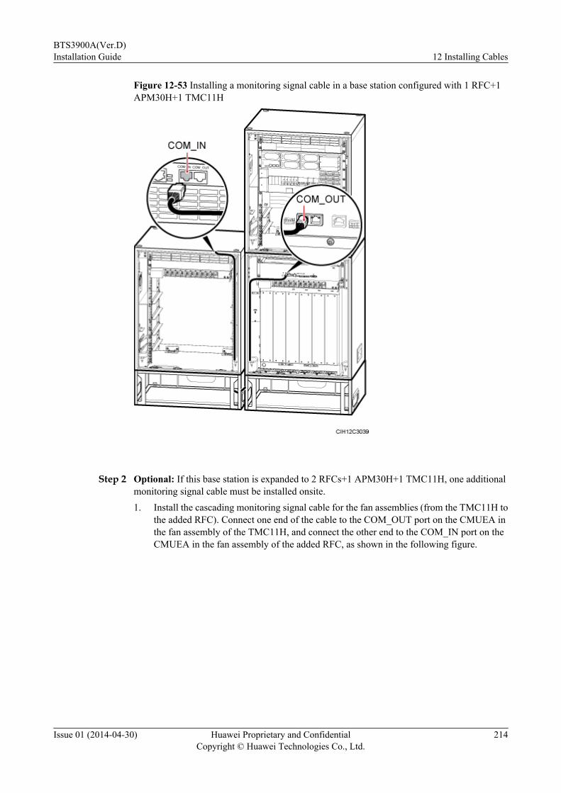
Figure 12-53 Installing a monitoring signal cable in a base station configured with 1 RFC+1APM30H+1 TMC11H
Step 2 Optional: If this base station is expanded to 2 RFCs+1 APM30H+1 TMC11H, one additionalmonitoring signal cable must be installed onsite.1. Install the cascading monitoring signal cable for the fan assemblies (from the TMC11H to
the added RFC). Connect one end of the cable to the COM_OUT port on the CMUEA inthe fan assembly of the TMC11H, and connect the other end to the COM_IN port on theCMUEA in the fan assembly of the added RFC, as shown in the following figure.
BTS3900A(Ver.D)Installation Guide 12 Installing Cables
Issue 01 (2014-04-30) Huawei Proprietary and ConfidentialCopyright © Huawei Technologies Co., Ltd.
214

Figure 12-54 Installing a monitoring signal cable in a base station configured with 2 RFCs+1APM30H+1 TMC11H
Step 3 Lay out the cables according to the instructions in 12.1 Cabling Requirements, and use cableties to bind them.
Step 4 Label the installed cables according to the instructions in Attaching an L-Shaped Label.
Step 5 Use a PVC corrugated pipe to protect the cables outside the cabinet, and tie the pipe to the cablehole on the cabinet.
----End
Scenario of 1 RFC+1 APM30H+1 IBBS200D/IBBS200T+1 TMC11H Expanded to 2RFCs+1 APM30H+2 IBBS200Ds/IBBS200Ts+1 TMC11H
This section describes the scenario where a base station configured with 1 RFC+1 APM30H+1IBBS200D/IBBS200T+1 TMC11H is expanded to 2 RFCs+1 APM30H+2 IBBS200Ds/IBBS200Ts+1 TMC11H.
Contextl When a base station is configured with 1 RFC+1 APM30H+1 IBBS200D/IBBS200T+1
TMC11H, two monitoring signal cables must be installed onsite.
BTS3900A(Ver.D)Installation Guide 12 Installing Cables
Issue 01 (2014-04-30) Huawei Proprietary and ConfidentialCopyright © Huawei Technologies Co., Ltd.
215

l If this base station is expanded to 2 RFCs+1 APM30H+2 IBBS200Ds/IBBS200Ts+1TMC11H, as shown in the following figure, two additional monitoring signal cables mustbe installed onsite.
l When a triple-mode base station is configured with two BBUs, the second BBU is installedin the APM30H or TMC11H. The second BBU does not perform the monitoring function.For the monitoring scheme in this scenario, see Monitoring Scheme.
Figure 12-55 1 RFC+1 APM30H+1 IBBS200D/IBBS200T+1 TMC11H expanded to 2 RFCs+1 APM30H+2 IBBS200Ds/IBBS200Ts+1 TMC11H
Procedure
Step 1 Install the monitoring signal cable for the battery cabinet (from the IBBS200D/IBBS200T to theAPM30H), as shown in the following figure.1. Connect one end of the cable to the COM_IN port on the CMUEA on the door of the
IBBS200D or IBBS200T.2. Connect the other end of the cable to the COM_485 port on the PMU in the APM30H.
BTS3900A(Ver.D)Installation Guide 12 Installing Cables
Issue 01 (2014-04-30) Huawei Proprietary and ConfidentialCopyright © Huawei Technologies Co., Ltd.
216

Figure 12-56 Installing the monitoring signal cables in a base station configured with 1 RFC+1APM30H+1 IBBS200D/IBBS200T+1 TMC11H (1)
Step 2 Install the cascading monitoring signal cable for the fan assemblies (from the RFC to theTMC11H), as shown in the following figure.1. Connect one end of the cable to the COM_OUT port on the CMUEA in the fan assembly
of the RFC.2. Connect the other end of the cable to the COM_IN port on the CMUEA in the fan assembly
of the TMC11H.
BTS3900A(Ver.D)Installation Guide 12 Installing Cables
Issue 01 (2014-04-30) Huawei Proprietary and ConfidentialCopyright © Huawei Technologies Co., Ltd.
217

Figure 12-57 Installing the monitoring signal cables in a base station configured with 1 RFC+1APM30H+1 IBBS200D/IBBS200T+1 TMC11H (2)
Step 3 Optional: If this base station is expanded to 2 RFCs+1 APM30H+2 IBBS200Ds/IBBS200Ts+1 TMC11H, two additional monitoring signal cables must be installed onsite.1. Install the cascading monitoring signal cable for the fan assemblies (from the TMC11H to
the added RFC). Connect one end of the cable to the COM_OUT port on the CMUEA inthe fan assembly of the TMC11H, and connect the other end to the COM_IN port on theCMUEA in the fan assembly of the added RFC, as shown by M1 in the following figure.
2. Install the monitoring signal cable between cascaded CMUEAs (from the originalIBBS200D/IBBS200T to the added IBBS200D/IBBS200T). Connect one end of the cableto the COM_OUT port on the CMUEA in the cabinet door of the original IBBS200D/IBBS200T, and connect the other end to the COM_IN port on the CMUEA in cabinet doorof the added IBBS200D/IBBS200T, as shown by M2 in the following figure.
BTS3900A(Ver.D)Installation Guide 12 Installing Cables
Issue 01 (2014-04-30) Huawei Proprietary and ConfidentialCopyright © Huawei Technologies Co., Ltd.
218

Figure 12-58 Installing the monitoring signal cables in a base station configured with 2 RFCs+1 APM30H+2 IBBS200Ds/IBBS200Ts+1 TMC11H
Step 4 Lay out the cables according to the instructions in 12.1 Cabling Requirements, and use cableties to bind them.
Step 5 Label the installed cables according to the instructions in Attaching an L-Shaped Label.
Step 6 Use a PVC corrugated pipe to protect the cables outside the cabinet, and tie the pipe to the cablehole on the cabinet.
----End
Scenario of 1 RFC+1 APM30H+2 IBBS200Ds/IBBS200Ts Expanded to 2 RFCs+1APM30H+2 IBBS200Ds/IBBS200Ts
This section describes the scenario where a base station configured with 1 RFC+1 APM30H+2IBBS200Ds/IBBS200Ts is expanded to 2 RFCs+1 APM30H+2 IBBS200Ds/IBBS200Ts.
Contextl When a base station is configured with 1 RFC+1 APM30H+2 IBBS200Ds/IBBS200Ts,
two monitoring signal cables must be installed onsite.
BTS3900A(Ver.D)Installation Guide 12 Installing Cables
Issue 01 (2014-04-30) Huawei Proprietary and ConfidentialCopyright © Huawei Technologies Co., Ltd.
219
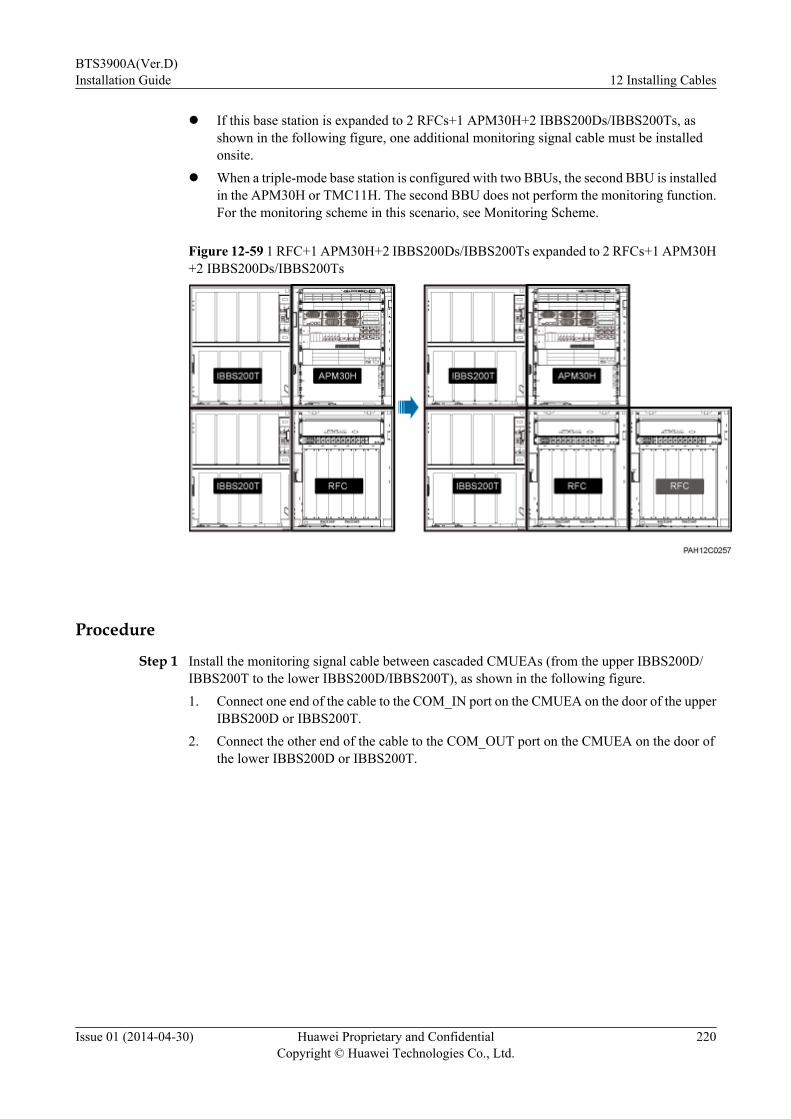
l If this base station is expanded to 2 RFCs+1 APM30H+2 IBBS200Ds/IBBS200Ts, asshown in the following figure, one additional monitoring signal cable must be installedonsite.
l When a triple-mode base station is configured with two BBUs, the second BBU is installedin the APM30H or TMC11H. The second BBU does not perform the monitoring function.For the monitoring scheme in this scenario, see Monitoring Scheme.
Figure 12-59 1 RFC+1 APM30H+2 IBBS200Ds/IBBS200Ts expanded to 2 RFCs+1 APM30H+2 IBBS200Ds/IBBS200Ts
Procedure
Step 1 Install the monitoring signal cable between cascaded CMUEAs (from the upper IBBS200D/IBBS200T to the lower IBBS200D/IBBS200T), as shown in the following figure.1. Connect one end of the cable to the COM_IN port on the CMUEA on the door of the upper
IBBS200D or IBBS200T.2. Connect the other end of the cable to the COM_OUT port on the CMUEA on the door of
the lower IBBS200D or IBBS200T.
BTS3900A(Ver.D)Installation Guide 12 Installing Cables
Issue 01 (2014-04-30) Huawei Proprietary and ConfidentialCopyright © Huawei Technologies Co., Ltd.
220
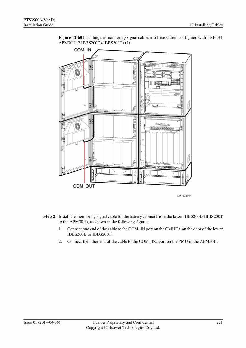
Figure 12-60 Installing the monitoring signal cables in a base station configured with 1 RFC+1APM30H+2 IBBS200Ds/IBBS200Ts (1)
Step 2 Install the monitoring signal cable for the battery cabinet (from the lower IBBS200D/IBBS200Tto the APM30H), as shown in the following figure.1. Connect one end of the cable to the COM_IN port on the CMUEA on the door of the lower
IBBS200D or IBBS200T.2. Connect the other end of the cable to the COM_485 port on the PMU in the APM30H.
BTS3900A(Ver.D)Installation Guide 12 Installing Cables
Issue 01 (2014-04-30) Huawei Proprietary and ConfidentialCopyright © Huawei Technologies Co., Ltd.
221
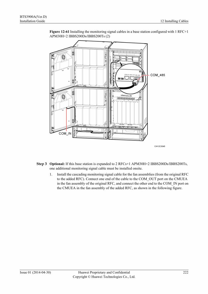
Figure 12-61 Installing the monitoring signal cables in a base station configured with 1 RFC+1APM30H+2 IBBS200Ds/IBBS200Ts (2)
Step 3 Optional: If this base station is expanded to 2 RFCs+1 APM30H+2 IBBS200Ds/IBBS200Ts,one additional monitoring signal cable must be installed onsite.1. Install the cascading monitoring signal cable for the fan assemblies (from the original RFC
to the added RFC). Connect one end of the cable to the COM_OUT port on the CMUEAin the fan assembly of the original RFC, and connect the other end to the COM_IN port onthe CMUEA in the fan assembly of the added RFC, as shown in the following figure.
BTS3900A(Ver.D)Installation Guide 12 Installing Cables
Issue 01 (2014-04-30) Huawei Proprietary and ConfidentialCopyright © Huawei Technologies Co., Ltd.
222

Figure 12-62 Installing a monitoring signal cable in a base station configured with 2 RFCs+1APM30H+2 IBBS200Ds/IBBS200Ts
Step 4 Lay out the cables according to the instructions in 12.1 Cabling Requirements, and use cableties to bind them.
Step 5 Label the installed cables according to the instructions in Attaching an L-Shaped Label.
Step 6 Use a PVC corrugated pipe to protect the cables outside the cabinet, and tie the pipe to the cablehole on the cabinet.
----End
Scenario of 1 RFC+1 APM30H+2 IBBS200Ds/IBBS200Ts+1 TMC11H Expanded to2 RFCs+1 APM30H+2 IBBS200Ds/IBBS200Ts+1 TMC11H
This section describes the scenario where a base station configured with 1 RFC+1 APM30H+2IBBS200Ds/IBBS200Ts+1 TMC11H is expanded to 2 RFCs+1 APM30H+2 IBBS200Ds/IBBS200Ts+1 TMC11H.
Contextl When a base station is configured with 1 RFC+1 APM30H+2 IBBS200Ds/IBBS200Ts+1
TMC11H, three monitoring signal cables must be installed onsite.
l If this base station is expanded to 2 RFCs+1 APM30H+2 IBBS200Ds/IBBS200Ts+1TMC11H, as shown in the following figure, one additional monitoring signal cable mustbe installed onsite.
BTS3900A(Ver.D)Installation Guide 12 Installing Cables
Issue 01 (2014-04-30) Huawei Proprietary and ConfidentialCopyright © Huawei Technologies Co., Ltd.
223

l When a triple-mode base station is configured with two BBUs, the second BBU is installedin the APM30H or TMC11H. The second BBU does not perform the monitoring function.For the monitoring scheme in this scenario, see Monitoring Scheme.
Figure 12-63 1 RFC+1 APM30H+2 IBBS200Ds/IBBS200Ts+1 TMC11H expanded to 2 RFCs+1 APM30H+2 IBBS200Ds/IBBS200Ts+1 TMC11H
Procedure
Step 1 Install the monitoring signal cable between cascaded CMUEAs (from the upper battery cabinetto the lower battery cabinet), as shown in the following figure.1. Connect one end of the cable to the COM_IN port on the CMUEA on the door of the upper
IBBS200D or IBBS200T.2. Connect the other end of the cable to the COM_OUT port on the CMUEA on the door of
the lower IBBS200D or IBBS200T.
BTS3900A(Ver.D)Installation Guide 12 Installing Cables
Issue 01 (2014-04-30) Huawei Proprietary and ConfidentialCopyright © Huawei Technologies Co., Ltd.
224

Figure 12-64 Installing the monitoring signal cables in a base station configured with 1 RFC+1APM30H+2 IBBS200Ds/IBBS200Ts+1 TMC11H (1)
Step 2 Install the monitoring signal cable for the battery cabinet (from the lower battery cabinet to theAPM30H), as shown in the following figure.1. Connect one end of the cable to the COM_IN port on the CMUEA on the door of the lower
IBBS200D or IBBS200T.2. Connect the other end of the cable to the COM_485 port on the PMU in the APM30H.
BTS3900A(Ver.D)Installation Guide 12 Installing Cables
Issue 01 (2014-04-30) Huawei Proprietary and ConfidentialCopyright © Huawei Technologies Co., Ltd.
225
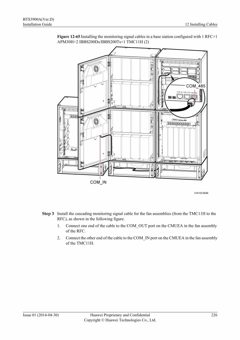
Figure 12-65 Installing the monitoring signal cables in a base station configured with 1 RFC+1APM30H+2 IBBS200Ds/IBBS200Ts+1 TMC11H (2)
Step 3 Install the cascading monitoring signal cable for the fan assemblies (from the TMC11H to theRFC), as shown in the following figure.1. Connect one end of the cable to the COM_OUT port on the CMUEA in the fan assembly
of the RFC.2. Connect the other end of the cable to the COM_IN port on the CMUEA in the fan assembly
of the TMC11H.
BTS3900A(Ver.D)Installation Guide 12 Installing Cables
Issue 01 (2014-04-30) Huawei Proprietary and ConfidentialCopyright © Huawei Technologies Co., Ltd.
226
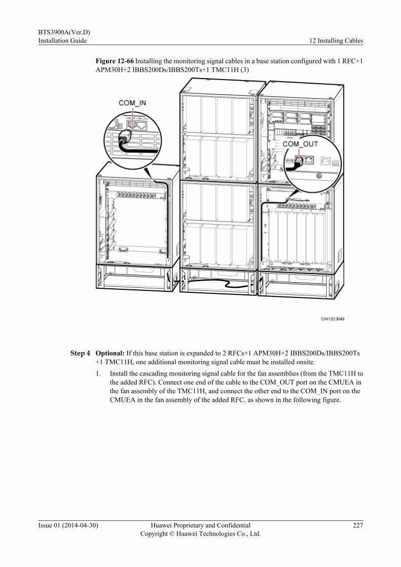
Figure 12-66 Installing the monitoring signal cables in a base station configured with 1 RFC+1APM30H+2 IBBS200Ds/IBBS200Ts+1 TMC11H (3)
Step 4 Optional: If this base station is expanded to 2 RFCs+1 APM30H+2 IBBS200Ds/IBBS200Ts+1 TMC11H, one additional monitoring signal cable must be installed onsite.1. Install the cascading monitoring signal cable for the fan assemblies (from the TMC11H to
the added RFC). Connect one end of the cable to the COM_OUT port on the CMUEA inthe fan assembly of the TMC11H, and connect the other end to the COM_IN port on theCMUEA in the fan assembly of the added RFC, as shown in the following figure.
BTS3900A(Ver.D)Installation Guide 12 Installing Cables
Issue 01 (2014-04-30) Huawei Proprietary and ConfidentialCopyright © Huawei Technologies Co., Ltd.
227

Figure 12-67 Installing a monitoring signal cable in a base station configured with 2 RFCs+1APM30H+2 IBBS200Ds/IBBS200Ts+1 TMC11H
Step 5 Lay out the cables according to the instructions in 12.1 Cabling Requirements, and use cableties to bind them.
Step 6 Label the installed cables according to the instructions in Attaching an L-Shaped Label.
Step 7 Use a PVC corrugated pipe to protect the cables outside the cabinet, and tie the pipe to the cablehole on the cabinet.
----End
Scenario of 1 RFC+1 APM30H+1 IBBS700D/IBBS700T+1 TMC11H and ItsExpansion Scenario
This section describes the scenario where a base station configured with 1 RFC+1 APM30H+1IBBS700D/IBBS700T+1 TMC11H is expanded to 2 RFCs+1 APM30H+1 IBBS700D/IBBS700T+1 TMC11H.
Contextl When a base station is configured with 1 RFC+1 APM30H+1 IBBS700D/IBBS700T+1
TMC11H, two monitoring signal cables must be installed onsite.
l If this base station is expanded to 2 RFCs+1 APM30H+1 IBBS2700D/IBBS700T+1TMC11H, as shown in the following figure, one additional monitoring signal cable mustbe installed onsite.
l When a triple-mode base station is configured with two BBUs, the second BBU is installedin the APM30H or TMC11H. The second BBU does not perform the monitoring function.For the monitoring scheme in this scenario, see Monitoring Scheme.
BTS3900A(Ver.D)Installation Guide 12 Installing Cables
Issue 01 (2014-04-30) Huawei Proprietary and ConfidentialCopyright © Huawei Technologies Co., Ltd.
228
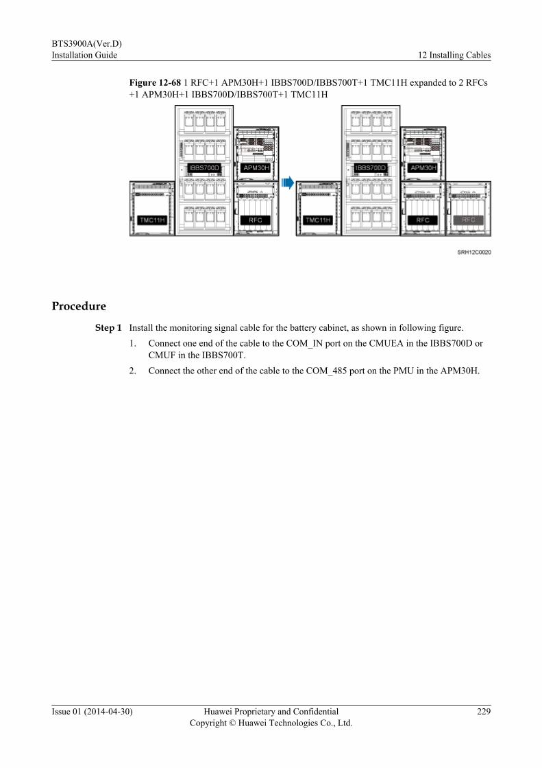
Figure 12-68 1 RFC+1 APM30H+1 IBBS700D/IBBS700T+1 TMC11H expanded to 2 RFCs+1 APM30H+1 IBBS700D/IBBS700T+1 TMC11H
Procedure
Step 1 Install the monitoring signal cable for the battery cabinet, as shown in following figure.1. Connect one end of the cable to the COM_IN port on the CMUEA in the IBBS700D or
CMUF in the IBBS700T.2. Connect the other end of the cable to the COM_485 port on the PMU in the APM30H.
BTS3900A(Ver.D)Installation Guide 12 Installing Cables
Issue 01 (2014-04-30) Huawei Proprietary and ConfidentialCopyright © Huawei Technologies Co., Ltd.
229
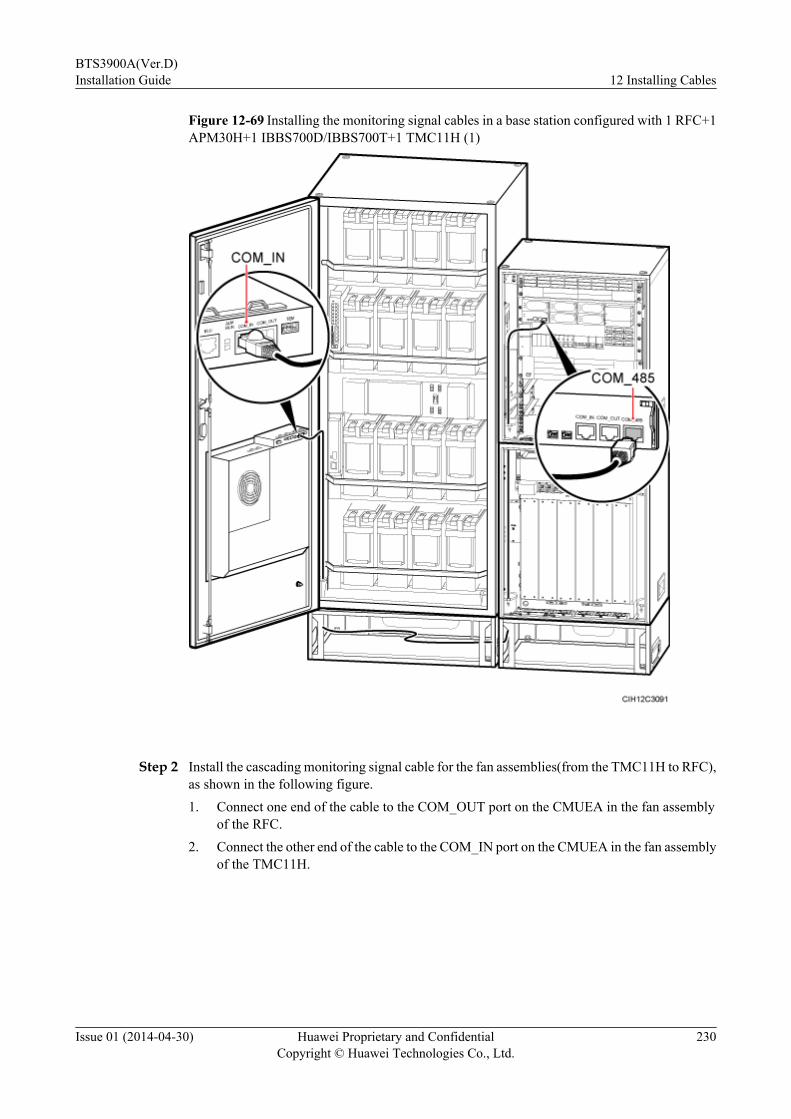
Figure 12-69 Installing the monitoring signal cables in a base station configured with 1 RFC+1APM30H+1 IBBS700D/IBBS700T+1 TMC11H (1)
Step 2 Install the cascading monitoring signal cable for the fan assemblies(from the TMC11H to RFC),as shown in the following figure.1. Connect one end of the cable to the COM_OUT port on the CMUEA in the fan assembly
of the RFC.2. Connect the other end of the cable to the COM_IN port on the CMUEA in the fan assembly
of the TMC11H.
BTS3900A(Ver.D)Installation Guide 12 Installing Cables
Issue 01 (2014-04-30) Huawei Proprietary and ConfidentialCopyright © Huawei Technologies Co., Ltd.
230
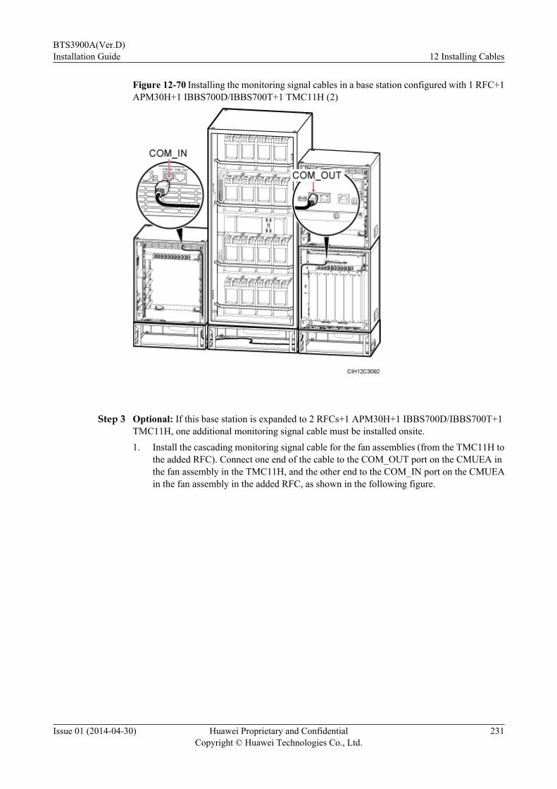
Figure 12-70 Installing the monitoring signal cables in a base station configured with 1 RFC+1APM30H+1 IBBS700D/IBBS700T+1 TMC11H (2)
Step 3 Optional: If this base station is expanded to 2 RFCs+1 APM30H+1 IBBS700D/IBBS700T+1TMC11H, one additional monitoring signal cable must be installed onsite.1. Install the cascading monitoring signal cable for the fan assemblies (from the TMC11H to
the added RFC). Connect one end of the cable to the COM_OUT port on the CMUEA inthe fan assembly in the TMC11H, and the other end to the COM_IN port on the CMUEAin the fan assembly in the added RFC, as shown in the following figure.
BTS3900A(Ver.D)Installation Guide 12 Installing Cables
Issue 01 (2014-04-30) Huawei Proprietary and ConfidentialCopyright © Huawei Technologies Co., Ltd.
231
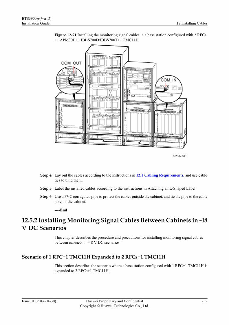
Figure 12-71 Installing the monitoring signal cables in a base station configured with 2 RFCs+1 APM30H+1 IBBS700D/IBBS700T+1 TMC11H
Step 4 Lay out the cables according to the instructions in 12.1 Cabling Requirements, and use cableties to bind them.
Step 5 Label the installed cables according to the instructions in Attaching an L-Shaped Label.
Step 6 Use a PVC corrugated pipe to protect the cables outside the cabinet, and tie the pipe to the cablehole on the cabinet.
----End
12.5.2 Installing Monitoring Signal Cables Between Cabinets in -48V DC Scenarios
This chapter describes the procedure and precautions for installing monitoring signal cablesbetween cabinets in -48 V DC scenarios.
Scenario of 1 RFC+1 TMC11H Expanded to 2 RFCs+1 TMC11HThis section describes the scenario where a base station configured with 1 RFC+1 TMC11H isexpanded to 2 RFCs+1 TMC11H.
BTS3900A(Ver.D)Installation Guide 12 Installing Cables
Issue 01 (2014-04-30) Huawei Proprietary and ConfidentialCopyright © Huawei Technologies Co., Ltd.
232
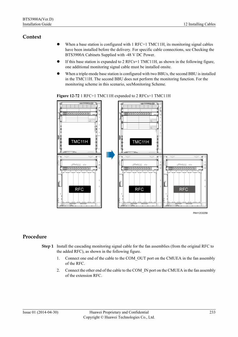
Contextl When a base station is configured with 1 RFC+1 TMC11H, its monitoring signal cables
have been installed before the delivery. For specific cable connections, see Checking theBTS3900A Cabinets Supplied with -48 V DC Power.
l If this base station is expanded to 2 RFCs+1 TMC11H, as shown in the following figure,one additional monitoring signal cable must be installed onsite.
l When a triple-mode base station is configured with two BBUs, the second BBU is installedin the TMC11H. The second BBU does not perform the monitoring function. For themonitoring scheme in this scenario, seeMonitoring Scheme.
Figure 12-72 1 RFC+1 TMC11H expanded to 2 RFCs+1 TMC11H
Procedure
Step 1 Install the cascading monitoring signal cable for the fan assemblies (from the original RFC tothe added RFC), as shown in the following figure.1. Connect one end of the cable to the COM_OUT port on the CMUEA in the fan assembly
of the RFC.2. Connect the other end of the cable to the COM_IN port on the CMUEA in the fan assembly
of the extension RFC.
BTS3900A(Ver.D)Installation Guide 12 Installing Cables
Issue 01 (2014-04-30) Huawei Proprietary and ConfidentialCopyright © Huawei Technologies Co., Ltd.
233

Figure 12-73 Installing a monitoring signal cable in a base station configured with 2 RFCs+1TMC11H
Step 2 Lay out the cables according to the instructions in 12.1 Cabling Requirements, and use cableties to bind them.
Step 3 Label the installed cables according to the instructions in Attaching an L-Shaped Label.
Step 4 Use a PVC corrugated pipe to protect the cables outside the cabinet, and tie the pipe to the cablehole on the cabinet.
----End
Scenario of 1 RFC+2 TMC11Hs Expanded to 2 RFCs+2 TMC11Hs
This section describes the scenario where a base station configured with 1 RFC+2 TMC11Hs isexpanded to 2 RFCs+2 TMC11Hs.
Contextl When a base station is configured with 1 RFC+2 TMC11Hs, one monitoring signal cable
must be installed onsite.
BTS3900A(Ver.D)Installation Guide 12 Installing Cables
Issue 01 (2014-04-30) Huawei Proprietary and ConfidentialCopyright © Huawei Technologies Co., Ltd.
234

l If this base station is expanded to 2 RFCs+2 TMC11Hs, as shown in the following figure,one additional monitoring signal cable must be installed onsite.
l When a triple-mode base station is configured with two BBUs, the second BBU is installedin the TMC11H. The second BBU does not perform the monitoring function. For themonitoring scheme in this scenario, seeMonitoring Scheme.
Figure 12-74 1 RFC+2 TMC11Hs expanded to 2 RFCs+2 TMC11Hs
Procedure
Step 1 Install the cascading monitoring signal cable for the fan assemblies (from the RFC to theextension TMC11H), as shown in the following figure.1. Connect one end of the cable to the COM_OUT port on the CMUEA in the fan assembly
of the RFC.2. Connect the other end of the cable to the COM_IN port on the CMUEA in the fan assembly
of the TMC11H.
BTS3900A(Ver.D)Installation Guide 12 Installing Cables
Issue 01 (2014-04-30) Huawei Proprietary and ConfidentialCopyright © Huawei Technologies Co., Ltd.
235

Figure 12-75 Installing a monitoring signal cable in a base station configured with 1 RFC+2TMC11Hs
Step 2 Optional: If this base station is expanded to 2 RFCs+2 TMC11Hs, one additional monitoringsignal cable must be installed onsite.1. Install the cascading monitoring signal cable for the fan assemblies (from the extension
TMC11H to the added RFC). Connect one end of the cable to the COM_OUT port on theCMUEA in the fan assembly of the extension TMC11H that is not configured with anyBBU, and connect the other end to the COM_IN port on the CMUEA in the fan assemblyof the added RFC, as shown in the following figure.
BTS3900A(Ver.D)Installation Guide 12 Installing Cables
Issue 01 (2014-04-30) Huawei Proprietary and ConfidentialCopyright © Huawei Technologies Co., Ltd.
236
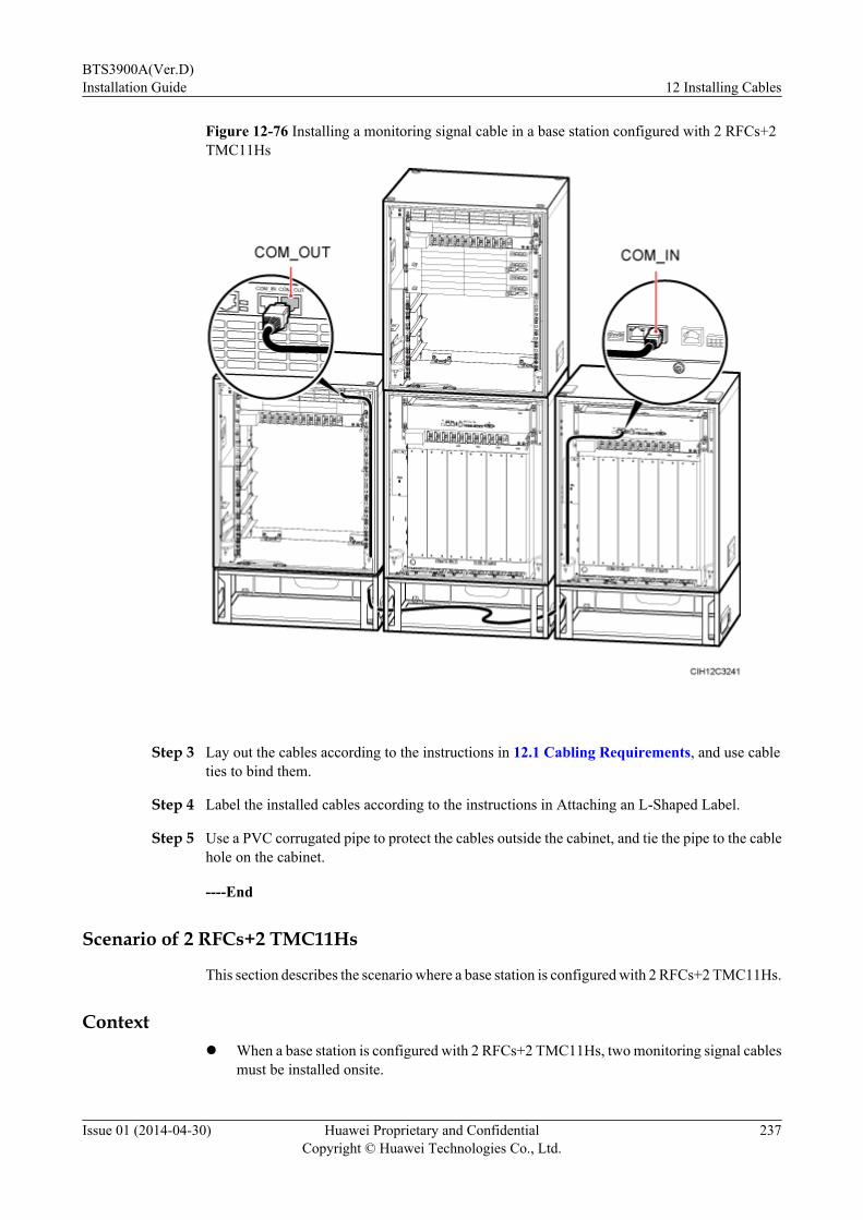
Figure 12-76 Installing a monitoring signal cable in a base station configured with 2 RFCs+2TMC11Hs
Step 3 Lay out the cables according to the instructions in 12.1 Cabling Requirements, and use cableties to bind them.
Step 4 Label the installed cables according to the instructions in Attaching an L-Shaped Label.
Step 5 Use a PVC corrugated pipe to protect the cables outside the cabinet, and tie the pipe to the cablehole on the cabinet.
----End
Scenario of 2 RFCs+2 TMC11Hs
This section describes the scenario where a base station is configured with 2 RFCs+2 TMC11Hs.
Contextl When a base station is configured with 2 RFCs+2 TMC11Hs, two monitoring signal cables
must be installed onsite.
BTS3900A(Ver.D)Installation Guide 12 Installing Cables
Issue 01 (2014-04-30) Huawei Proprietary and ConfidentialCopyright © Huawei Technologies Co., Ltd.
237

l When a triple-mode base station is configured with two BBUs, the second BBU is installedin the TMC11H. The second BBU does not perform the monitoring function. For themonitoring scheme in this scenario, seeMonitoring Scheme.
Procedure
Step 1 Install the cascading monitoring signal cable for the fan assemblies (from the RFC to the RFC),as shown in the following figure.
1. Connect one end of the cable to the COM_OUT port on the CMUEA in the fan assemblyof the left RFC.
2. Connect the other end of the cable to the COM_IN port on the CMUEA in the fan assemblyof the right RFC.
Figure 12-77 Installing the monitoring signal cables in a base station configured with 2 RFCs+2 TMC11Hs (1)
Step 2 Install the cascading monitoring signal cable for the fan assemblies (from the RFC to theextension TMC11H), as shown in the following figure.
1. Connect one end of the cable to the COM_OUT port on the CMUEA in the fan assemblyof the right RFC.
BTS3900A(Ver.D)Installation Guide 12 Installing Cables
Issue 01 (2014-04-30) Huawei Proprietary and ConfidentialCopyright © Huawei Technologies Co., Ltd.
238
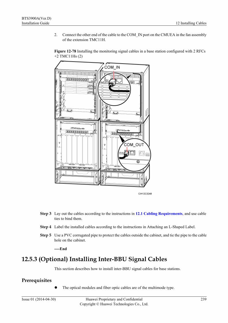
2. Connect the other end of the cable to the COM_IN port on the CMUEA in the fan assemblyof the extension TMC11H.
Figure 12-78 Installing the monitoring signal cables in a base station configured with 2 RFCs+2 TMC11Hs (2)
Step 3 Lay out the cables according to the instructions in 12.1 Cabling Requirements, and use cableties to bind them.
Step 4 Label the installed cables according to the instructions in Attaching an L-Shaped Label.
Step 5 Use a PVC corrugated pipe to protect the cables outside the cabinet, and tie the pipe to the cablehole on the cabinet.
----End
12.5.3 (Optional) Installing Inter-BBU Signal CablesThis section describes how to install inter-BBU signal cables for base stations.
Prerequisitesl The optical modules and fiber optic cables are of the multimode type.
BTS3900A(Ver.D)Installation Guide 12 Installing Cables
Issue 01 (2014-04-30) Huawei Proprietary and ConfidentialCopyright © Huawei Technologies Co., Ltd.
239

l The rate of optical modules installed in the UMPT and UCIU is 5 Gbit/s or 2.5 Gbit/s.
l The inter-WBBPf signal cable is a QSFP electrical cable.
Optical modules can be divided into single- and multimode optical modules, which can bedistinguished as follows:
l The puller of a single-mode optical module is blue and the puller of a multimode opticalmodule is black or gray.
l The transmission mode is displayed as "SM" on the label of a single-mode optical moduleand "MM" on the label of a multimode optical module.
There is a label on each optical module, which provides information such as the rate, wavelength,and transmission mode, as shown in the following figure.
Figure 12-79 Label on an optical module
(1) Rate (2) Wavelength (3) Transmission mode
Context
Procedure
Step 1 Remove the dustproof cap from the corresponding port on the BBU and install the opticalmodules in BBU 0 and BBU 1, as shown in the following figure.
1. Lower the puller of the optical module.
2. Insert the optical module into the port.
3. Raise the puller of the optical module.
Figure 12-80 Installing the optical module
Step 2 Remove dustproof caps from both ends of the fiber optic cable, as shown in Figure 12-81.
BTS3900A(Ver.D)Installation Guide 12 Installing Cables
Issue 01 (2014-04-30) Huawei Proprietary and ConfidentialCopyright © Huawei Technologies Co., Ltd.
240
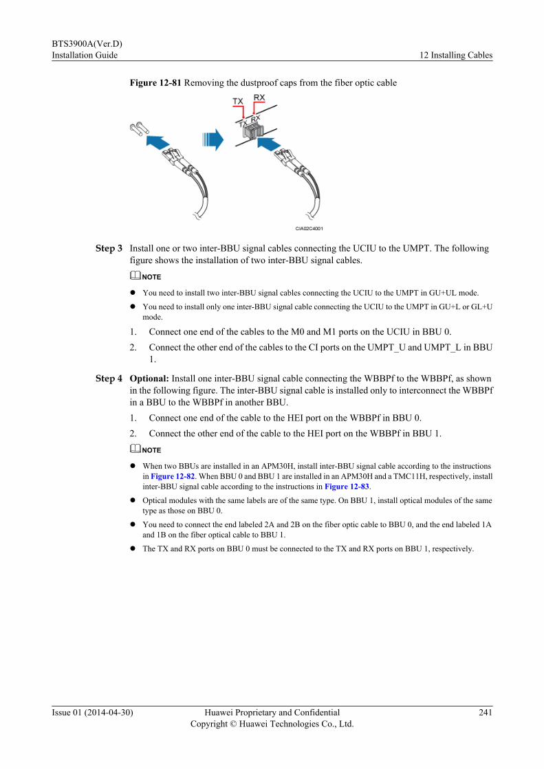
Figure 12-81 Removing the dustproof caps from the fiber optic cable
Step 3 Install one or two inter-BBU signal cables connecting the UCIU to the UMPT. The followingfigure shows the installation of two inter-BBU signal cables.
NOTE
l You need to install two inter-BBU signal cables connecting the UCIU to the UMPT in GU+UL mode.
l You need to install only one inter-BBU signal cable connecting the UCIU to the UMPT in GU+L or GL+Umode.
1. Connect one end of the cables to the M0 and M1 ports on the UCIU in BBU 0.2. Connect the other end of the cables to the CI ports on the UMPT_U and UMPT_L in BBU
1.
Step 4 Optional: Install one inter-BBU signal cable connecting the WBBPf to the WBBPf, as shownin the following figure. The inter-BBU signal cable is installed only to interconnect the WBBPfin a BBU to the WBBPf in another BBU.1. Connect one end of the cable to the HEI port on the WBBPf in BBU 0.2. Connect the other end of the cable to the HEI port on the WBBPf in BBU 1.
NOTE
l When two BBUs are installed in an APM30H, install inter-BBU signal cable according to the instructionsin Figure 12-82. When BBU 0 and BBU 1 are installed in an APM30H and a TMC11H, respectively, installinter-BBU signal cable according to the instructions in Figure 12-83.
l Optical modules with the same labels are of the same type. On BBU 1, install optical modules of the sametype as those on BBU 0.
l You need to connect the end labeled 2A and 2B on the fiber optic cable to BBU 0, and the end labeled 1Aand 1B on the fiber optical cable to BBU 1.
l The TX and RX ports on BBU 0 must be connected to the TX and RX ports on BBU 1, respectively.
BTS3900A(Ver.D)Installation Guide 12 Installing Cables
Issue 01 (2014-04-30) Huawei Proprietary and ConfidentialCopyright © Huawei Technologies Co., Ltd.
241

Figure 12-82 Installing inter-BBU signal cables (1)
BTS3900A(Ver.D)Installation Guide 12 Installing Cables
Issue 01 (2014-04-30) Huawei Proprietary and ConfidentialCopyright © Huawei Technologies Co., Ltd.
242
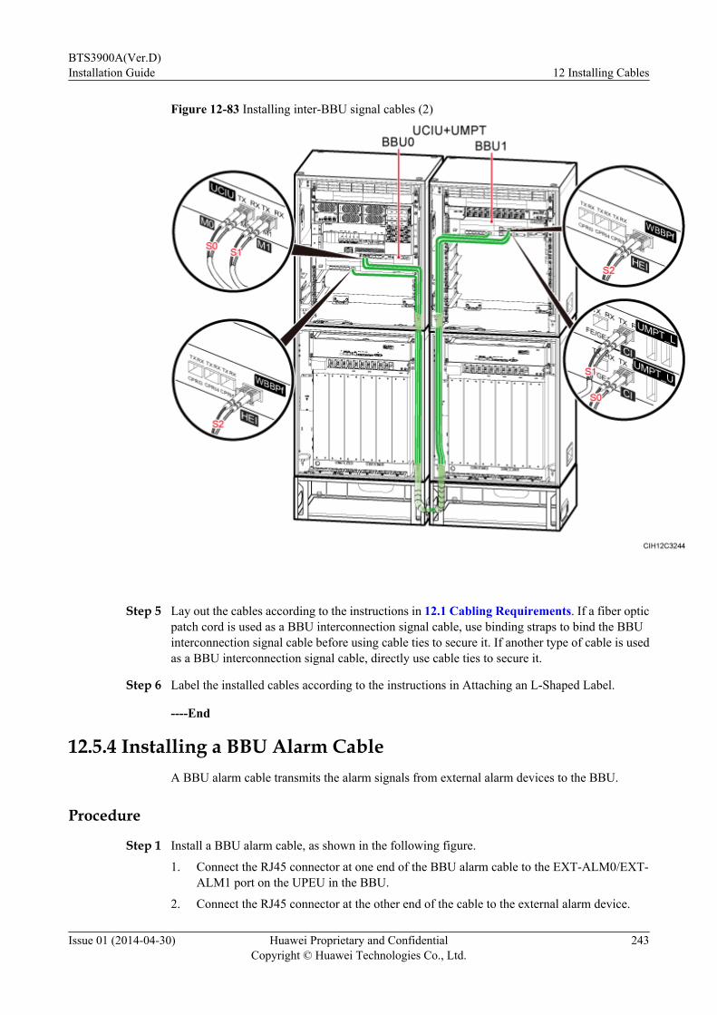
Figure 12-83 Installing inter-BBU signal cables (2)
Step 5 Lay out the cables according to the instructions in 12.1 Cabling Requirements. If a fiber opticpatch cord is used as a BBU interconnection signal cable, use binding straps to bind the BBUinterconnection signal cable before using cable ties to secure it. If another type of cable is usedas a BBU interconnection signal cable, directly use cable ties to secure it.
Step 6 Label the installed cables according to the instructions in Attaching an L-Shaped Label.
----End
12.5.4 Installing a BBU Alarm CableA BBU alarm cable transmits the alarm signals from external alarm devices to the BBU.
Procedure
Step 1 Install a BBU alarm cable, as shown in the following figure.
1. Connect the RJ45 connector at one end of the BBU alarm cable to the EXT-ALM0/EXT-ALM1 port on the UPEU in the BBU.
2. Connect the RJ45 connector at the other end of the cable to the external alarm device.
BTS3900A(Ver.D)Installation Guide 12 Installing Cables
Issue 01 (2014-04-30) Huawei Proprietary and ConfidentialCopyright © Huawei Technologies Co., Ltd.
243
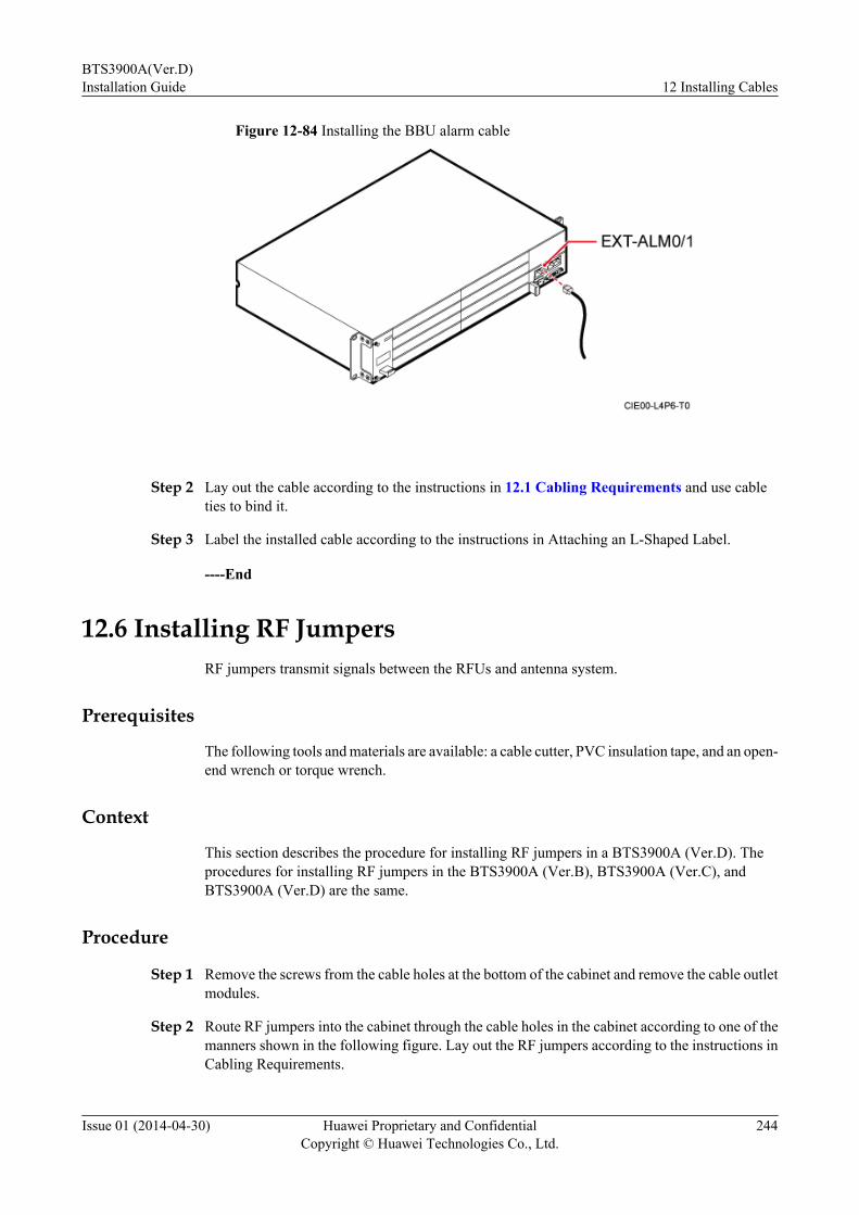
Figure 12-84 Installing the BBU alarm cable
Step 2 Lay out the cable according to the instructions in 12.1 Cabling Requirements and use cableties to bind it.
Step 3 Label the installed cable according to the instructions in Attaching an L-Shaped Label.
----End
12.6 Installing RF JumpersRF jumpers transmit signals between the RFUs and antenna system.
Prerequisites
The following tools and materials are available: a cable cutter, PVC insulation tape, and an open-end wrench or torque wrench.
Context
This section describes the procedure for installing RF jumpers in a BTS3900A (Ver.D). Theprocedures for installing RF jumpers in the BTS3900A (Ver.B), BTS3900A (Ver.C), andBTS3900A (Ver.D) are the same.
Procedure
Step 1 Remove the screws from the cable holes at the bottom of the cabinet and remove the cable outletmodules.
Step 2 Route RF jumpers into the cabinet through the cable holes in the cabinet according to one of themanners shown in the following figure. Lay out the RF jumpers according to the instructions inCabling Requirements.
BTS3900A(Ver.D)Installation Guide 12 Installing Cables
Issue 01 (2014-04-30) Huawei Proprietary and ConfidentialCopyright © Huawei Technologies Co., Ltd.
244

Figure 12-85 Routing of RF jumpers
Step 3 Install RF jumpers, as shown in the following figure.
NOTICEConnect each RF jumper securely to prevent RF signal leakage.
Figure 12-86 Installing RF jumpers for interconnected RFUs
NOTE
Inter-RFU RF signal cables have been installed in the cabinet before delivery. You only need to checkwhether the cables are securely connected.
BTS3900A(Ver.D)Installation Guide 12 Installing Cables
Issue 01 (2014-04-30) Huawei Proprietary and ConfidentialCopyright © Huawei Technologies Co., Ltd.
245

Figure 12-87 Installing RF jumpers for independent RFUs
1. Connect the jumper DIN connector to the ANT port on the RFU panel.
2. Use a 32 mm (1.26 in.) torque wrench to tighten the two DIN connectors from bottom totop with a torque between 25 N·m (221.27 lbf·in.) and 35 N·m (309.78 lbf·in.), as shownin the following figure.
Figure 12-88 Tightening the DIN connectors
Step 4 Seal the cable holes for RF jumpers, as shown in the following figure.
1. Route the RF jumpers through the corresponding cable holes, and install the cable outletmodules on the bottom of the cabinet.
2. Use rubber plugs to seal any unused cable holes in the cable outlet modules.
3. Insert the metal piece and use a torque screwdriver to tighten the screws to 1.2 N·m (10.62lbf·in.).
BTS3900A(Ver.D)Installation Guide 12 Installing Cables
Issue 01 (2014-04-30) Huawei Proprietary and ConfidentialCopyright © Huawei Technologies Co., Ltd.
246

NOTE
The following figure shows how to seal the cable holes for RF jumpers in a BTS3900A (Ver.D).
Figure 12-89 Sealing the cable holes for RF jumpers
(1) RF jumper (2) Cable outlet module (3) Metal piece
(4) Screw (5) Rubber plugs -
NOTE
The following figure shows how to seal the cable holes for RF jumpers in a BTS3900A (Ver.B) orBTS3900A (Ver.C).
Figure 12-90 Sealing the cable holes for RF jumpers
(1) RF jumper (2) Cable outlet module (3) Metal piece
(4) Screw (5) Rubber plug -
Step 5 Attach color codings to the RF jumpers according to the instructions in Attaching the ColorRing.
BTS3900A(Ver.D)Installation Guide 12 Installing Cables
Issue 01 (2014-04-30) Huawei Proprietary and ConfidentialCopyright © Huawei Technologies Co., Ltd.
247
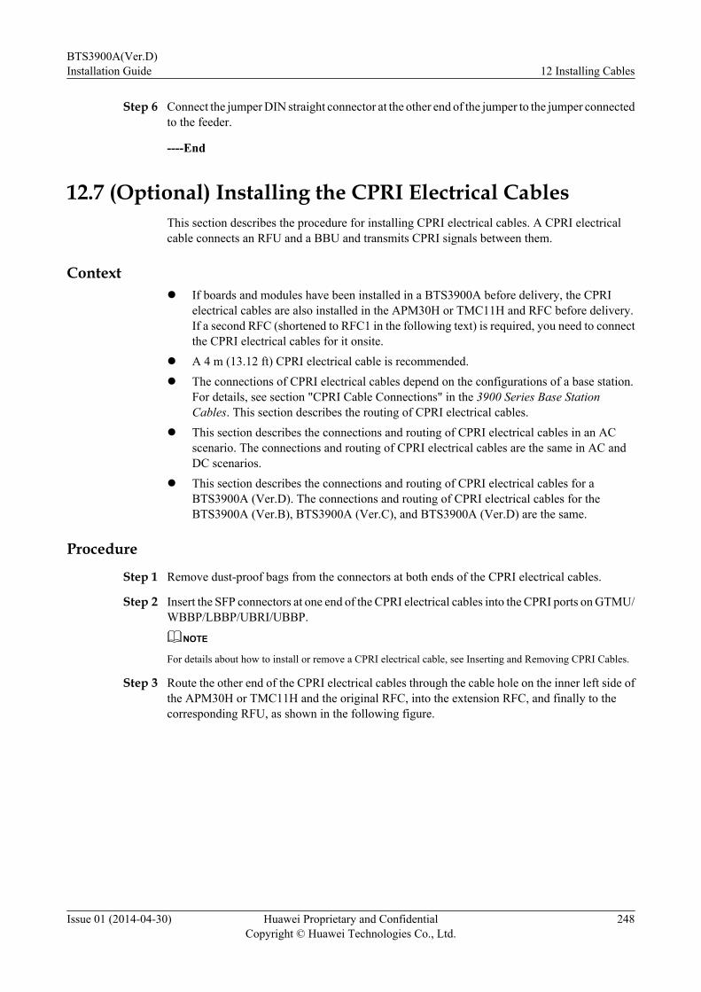
Step 6 Connect the jumper DIN straight connector at the other end of the jumper to the jumper connectedto the feeder.
----End
12.7 (Optional) Installing the CPRI Electrical CablesThis section describes the procedure for installing CPRI electrical cables. A CPRI electricalcable connects an RFU and a BBU and transmits CPRI signals between them.
Contextl If boards and modules have been installed in a BTS3900A before delivery, the CPRI
electrical cables are also installed in the APM30H or TMC11H and RFC before delivery.If a second RFC (shortened to RFC1 in the following text) is required, you need to connectthe CPRI electrical cables for it onsite.
l A 4 m (13.12 ft) CPRI electrical cable is recommended.l The connections of CPRI electrical cables depend on the configurations of a base station.
For details, see section "CPRI Cable Connections" in the 3900 Series Base StationCables. This section describes the routing of CPRI electrical cables.
l This section describes the connections and routing of CPRI electrical cables in an ACscenario. The connections and routing of CPRI electrical cables are the same in AC andDC scenarios.
l This section describes the connections and routing of CPRI electrical cables for aBTS3900A (Ver.D). The connections and routing of CPRI electrical cables for theBTS3900A (Ver.B), BTS3900A (Ver.C), and BTS3900A (Ver.D) are the same.
Procedure
Step 1 Remove dust-proof bags from the connectors at both ends of the CPRI electrical cables.
Step 2 Insert the SFP connectors at one end of the CPRI electrical cables into the CPRI ports on GTMU/WBBP/LBBP/UBRI/UBBP.
NOTE
For details about how to install or remove a CPRI electrical cable, see Inserting and Removing CPRI Cables.
Step 3 Route the other end of the CPRI electrical cables through the cable hole on the inner left side ofthe APM30H or TMC11H and the original RFC, into the extension RFC, and finally to thecorresponding RFU, as shown in the following figure.
BTS3900A(Ver.D)Installation Guide 12 Installing Cables
Issue 01 (2014-04-30) Huawei Proprietary and ConfidentialCopyright © Huawei Technologies Co., Ltd.
248

Figure 12-91 Installing the CPRI electrical cables
Step 4 Insert the SFP connectors at the other end of the CPRI electrical cables into the CPRI0 ports onthe RFUs, as shown in Figure 12-91.
NOTE
l Wind and bind the redundant parts of CPRI electrical cables at the top of the DCDU-12A in the RFC or inthe base of the RFC.
l For the BTS3900A (Ver.D), lay out the cables according to the manners in Figure 12-91. For the BTS3900A(Ver.B) and BTS3900A (Ver.C), ensure that the cables are routed to the RFU through the cable bridge abovethe RFUs in RFC1.
l During the routing for the BTS3900A (Ver.B) and BTS3900A (Ver.C), bind the cables. Tie the cables onthe binding bracket by leading the cable ties around the cable in a diagonal way to upper and lower cablingteeth. Ensure that the heads of all the cable ties are outside the cabling teeth, as shown in the following figure.
BTS3900A(Ver.D)Installation Guide 12 Installing Cables
Issue 01 (2014-04-30) Huawei Proprietary and ConfidentialCopyright © Huawei Technologies Co., Ltd.
249
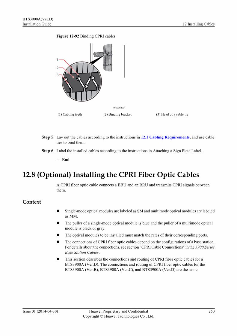
Figure 12-92 Binding CPRI cables
(1) Cabling teeth (2) Binding bracket (3) Head of a cable tie
Step 5 Lay out the cables according to the instructions in 12.1 Cabling Requirements, and use cableties to bind them.
Step 6 Label the installed cables according to the instructions in Attaching a Sign Plate Label.
----End
12.8 (Optional) Installing the CPRI Fiber Optic CablesA CPRI fiber optic cable connects a BBU and an RRU and transmits CPRI signals betweenthem.
Contextl Single-mode optical modules are labeled as SM and multimode optical modules are labeled
as MM.l The puller of a single-mode optical module is blue and the puller of a multimode optical
module is black or gray.l The optical modules to be installed must match the rates of their corresponding ports.l The connections of CPRI fiber optic cables depend on the configurations of a base station.
For details about the connections, see section "CPRI Cable Connections" in the 3900 SeriesBase Station Cables.
l This section describes the connections and routing of CPRI fiber optic cables for aBTS3900A (Ver.D). The connections and routing of CPRI fiber optic cables for theBTS3900A (Ver.B), BTS3900A (Ver.C), and BTS3900A (Ver.D) are the same.
BTS3900A(Ver.D)Installation Guide 12 Installing Cables
Issue 01 (2014-04-30) Huawei Proprietary and ConfidentialCopyright © Huawei Technologies Co., Ltd.
250
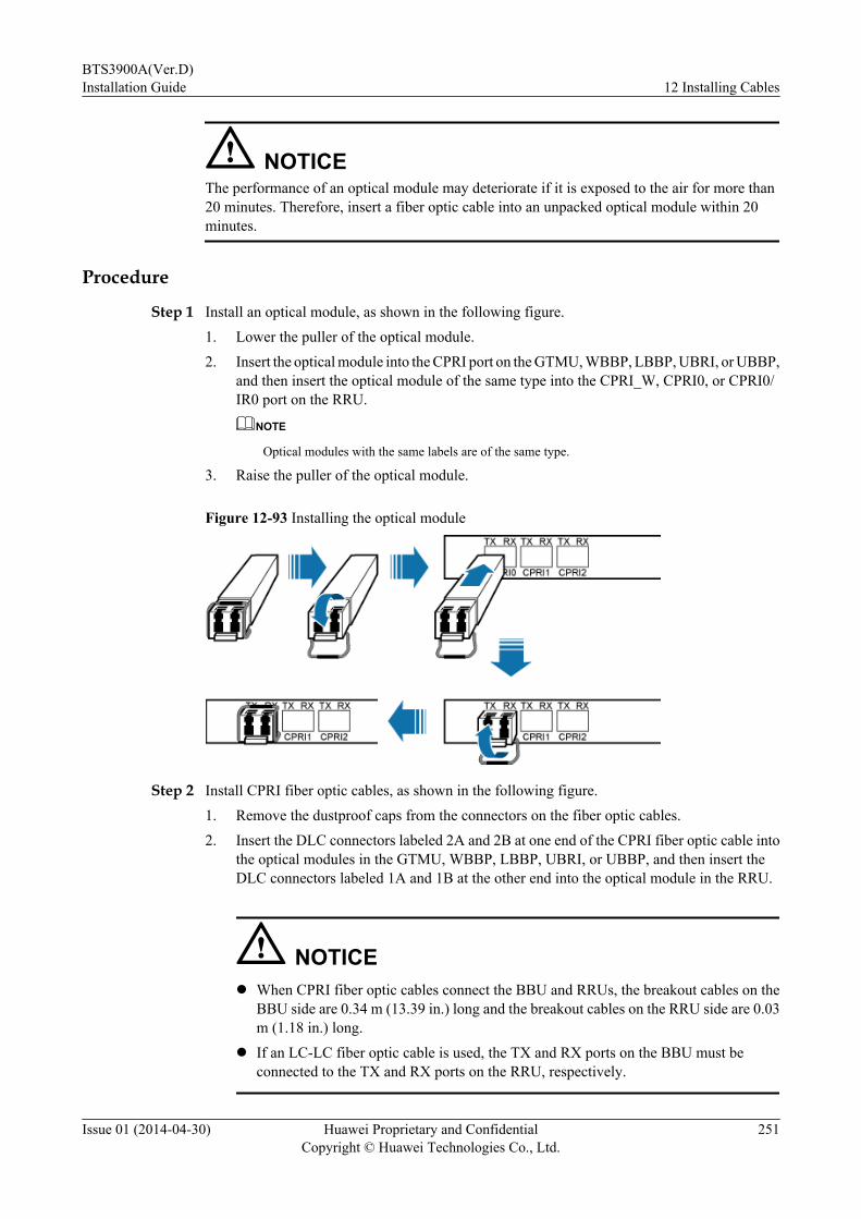
NOTICEThe performance of an optical module may deteriorate if it is exposed to the air for more than20 minutes. Therefore, insert a fiber optic cable into an unpacked optical module within 20minutes.
Procedure
Step 1 Install an optical module, as shown in the following figure.1. Lower the puller of the optical module.2. Insert the optical module into the CPRI port on the GTMU, WBBP, LBBP, UBRI, or UBBP,
and then insert the optical module of the same type into the CPRI_W, CPRI0, or CPRI0/IR0 port on the RRU.
NOTE
Optical modules with the same labels are of the same type.
3. Raise the puller of the optical module.
Figure 12-93 Installing the optical module
Step 2 Install CPRI fiber optic cables, as shown in the following figure.1. Remove the dustproof caps from the connectors on the fiber optic cables.2. Insert the DLC connectors labeled 2A and 2B at one end of the CPRI fiber optic cable into
the optical modules in the GTMU, WBBP, LBBP, UBRI, or UBBP, and then insert theDLC connectors labeled 1A and 1B at the other end into the optical module in the RRU.
NOTICEl When CPRI fiber optic cables connect the BBU and RRUs, the breakout cables on the
BBU side are 0.34 m (13.39 in.) long and the breakout cables on the RRU side are 0.03m (1.18 in.) long.
l If an LC-LC fiber optic cable is used, the TX and RX ports on the BBU must beconnected to the TX and RX ports on the RRU, respectively.
BTS3900A(Ver.D)Installation Guide 12 Installing Cables
Issue 01 (2014-04-30) Huawei Proprietary and ConfidentialCopyright © Huawei Technologies Co., Ltd.
251

Figure 12-94 Installing CPRI fiber optic cables
Step 3 Route the CPRI fiber optic cable out of the cabinet from the cable hole on the bottom left side.For details about how to route the cable, see 12.1 Cabling Requirements.
Step 4 Label the installed cables according to the instructions in Attaching a Sign Plate Label.
----End
BTS3900A(Ver.D)Installation Guide 12 Installing Cables
Issue 01 (2014-04-30) Huawei Proprietary and ConfidentialCopyright © Huawei Technologies Co., Ltd.
252

13 Installation Checklist
After the cabinets and devices are installed, you need to check the installation items, installationenvironment, and cable-related items.
Cabinet Installation Checklist
The following table lists the items to be checked for the cabinet installation.
Table 13-1 Cabinet installation checklist
No. Item
1 The installation position of the cabinet strictly complies with the engineeringdesign.
2 The base is securely installed.
3 All the bolts, including those for electrical connections, are tightened. The springwashers and the flat washers are installed in the correct sequence.
4 The cabinet is neat and clean.
5 The paint on the surface is intact. The damaged paint is repaired. For details, see15.2 Repainting.
6 Labels, tags, and nameplates are correct, legible, and complete.
Installation Environment Checklist
The following table lists the items to be checked for the installation environment.
Table 13-2 Installation environment checklist
No. Item
1 No excessive straps or adhesive tapes are left on the cables.
BTS3900A(Ver.D)Installation Guide 13 Installation Checklist
Issue 01 (2014-04-30) Huawei Proprietary and ConfidentialCopyright © Huawei Technologies Co., Ltd.
253
No. Item
2 No tapes, tails of cable ties, paper, or packing bags are left around the cabinet.
3 Antirust powder on the door of the cabinet is cleared.
Electrical Connection ChecklistThe following table lists the items to be checked for electrical connections.
Table 13-3 Electrical connection checklist
No. Item
1 All self-made PGND cables are copper-based with proper core diameters. Thereshould not be any switch or fuse in the grounding system. No short circuit is allowed.
2 The PGND cable is securely connected and the AC input power cable and cablesin the cabinet are correctly connected according to the electrical design of the powersystem. The screws are tightened. In addition, the inputs or outputs are not short-circuited.
3 The redundant part of the power cable or PGND cable is cut off rather than coiled.
4 The terminals at both ends of the power cable or PGND cable are securely solderedor crimped.
5 The bare wires and the terminal handles at the wiring terminals are coated with heatshrink tubing.
6 The flat washers and the spring washers are well mounted on all OT terminals.
7 The exterior of the storage battery is intact without any scratch, dent, or crack.
8 The shell of the storage battery is clean without any leakage trace.
9 The wiring terminal on the storage battery stands properly without any damage, andthe post is not covered with any acid substances.
10 The pressure relief valve of the battery is not deformed, and no liquid leaks.
11 The power cables for the storage batteries are correctly connected to the positiveand negative poles.
12 The voltage of the storage battery is normal.l The voltage of a 2 V storage battery ranges from 1.8 V to 2.35 V.l The voltage of a 12 V storage battery ranges from 10.8 V to 14.1 V.l The total voltage of the storage batteries ranges from 43.2 V to 56.4 V.
13 The circuit breakers for the storage batteries are set to OFF.
BTS3900A(Ver.D)Installation Guide 13 Installation Checklist
Issue 01 (2014-04-30) Huawei Proprietary and ConfidentialCopyright © Huawei Technologies Co., Ltd.
254
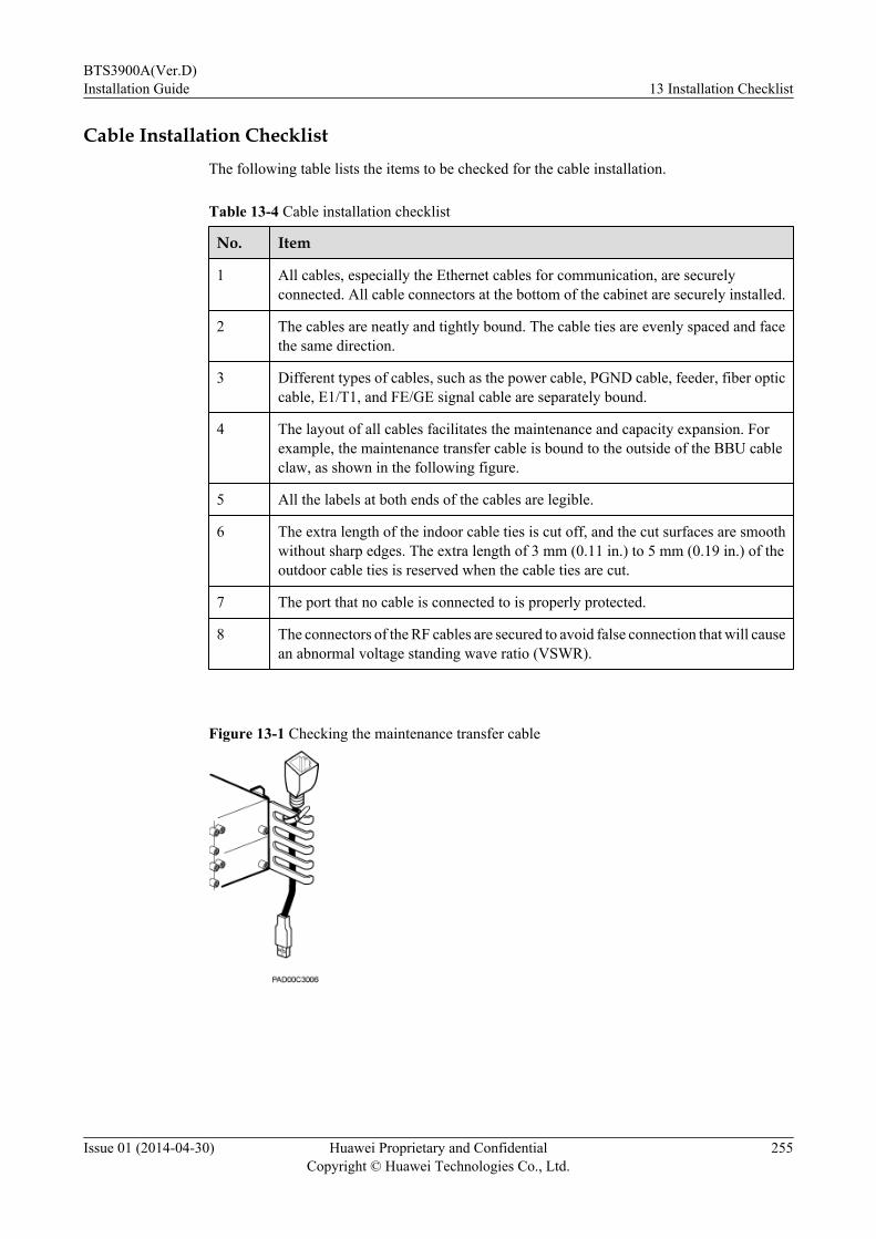
Cable Installation ChecklistThe following table lists the items to be checked for the cable installation.
Table 13-4 Cable installation checklist
No. Item
1 All cables, especially the Ethernet cables for communication, are securelyconnected. All cable connectors at the bottom of the cabinet are securely installed.
2 The cables are neatly and tightly bound. The cable ties are evenly spaced and facethe same direction.
3 Different types of cables, such as the power cable, PGND cable, feeder, fiber opticcable, E1/T1, and FE/GE signal cable are separately bound.
4 The layout of all cables facilitates the maintenance and capacity expansion. Forexample, the maintenance transfer cable is bound to the outside of the BBU cableclaw, as shown in the following figure.
5 All the labels at both ends of the cables are legible.
6 The extra length of the indoor cable ties is cut off, and the cut surfaces are smoothwithout sharp edges. The extra length of 3 mm (0.11 in.) to 5 mm (0.19 in.) of theoutdoor cable ties is reserved when the cable ties are cut.
7 The port that no cable is connected to is properly protected.
8 The connectors of the RF cables are secured to avoid false connection that will causean abnormal voltage standing wave ratio (VSWR).
Figure 13-1 Checking the maintenance transfer cable
BTS3900A(Ver.D)Installation Guide 13 Installation Checklist
Issue 01 (2014-04-30) Huawei Proprietary and ConfidentialCopyright © Huawei Technologies Co., Ltd.
255

14 Powering On a Base Station
This section describes how to power on a base station and handle a failure in the power supplyto the components in a cabinet.
Prerequisitesl Input power cables for the BTS3900A are correctly connected.l The power supply to the BTS3900A meets the requirements of the power system.l The external power supply to the BTS3900A has been shut off.l All circuit breakers in the APM30H have been set to OFF.l All circuit breakers (if any) on the DCDUs in the RFC and TMC11H have been set to OFF.l All circuit breakers on the power distribution box in the IBBS200D or IBBS200T have
been set to OFF.l Switch on the power distribution box in the IBBS700D or IBBS700T has been set to OFF.l Circuit breakers on the boards in the BBU have been set to OFF.l Boards, modules, and cables have been installed in the cabinet.
Context
DANGERExercise caution when performing a power-on check, which involves some high voltageoperations. Direct contact with the input voltage or indirect contact with the input voltage usinga damp object may be fatal.
BTS3900A(Ver.D)Installation Guide 14 Powering On a Base Station
Issue 01 (2014-04-30) Huawei Proprietary and ConfidentialCopyright © Huawei Technologies Co., Ltd.
256

NOTICEl Power on a cabinet or BBU within 7 days after unpacking it. If you power off a cabinet or
BBU for maintenance, restore power to the cabinet or BBU within 48 hours.l Power on an RRU within 24 hours after unpacking it. If you power off an RRU for
maintenance, restore power to the RRU within 24 hours.
Table 14-1 Circuit breakers in BTS3900A base stations
BaseStation
Power Device(1) Circuit Breaker
BTS3900A(Ver.B)
EPS 01A or EPS 01C,DCDU-01, DCDU-03B,DCDU-03C, or powerdistribution box
l Circuit breakers on the EPS 01A or EPS 01Cl BAT_SW0, BAT_SW1, and FAN/TEC_SW2
circuit breakers on the power distribution boxin an IBBS200D or IBBS200T
l SPARE2, SPARE1, BBU, FAN, and RFU0 toRFU5 circuit breakers on the DCDU-01 (Thecircuit breakers control the power input to theBBU, fan assembly, and RFUs.)
l SW0 to SW9 circuit breakers on theDCDU-03B (The circuit breakers control thepower input to the RRU 0 to RRU 5, BBU, fanassembly, and customer transmissionequipment.)
l SW0 to SW9 circuit breakers on theDCDU-03C (The circuit breakers control thepower input to the BBU, fan assembly, andcustomer transmission equipment.)
BTS3900A(Ver.D)Installation Guide 14 Powering On a Base Station
Issue 01 (2014-04-30) Huawei Proprietary and ConfidentialCopyright © Huawei Technologies Co., Ltd.
257

BaseStation
Power Device(1) Circuit Breaker
BTS3900A(Ver.C)
EPU03A-02 orEPU03A-04,DCDU-11A,DCDU-11B,DCDU-11C, and powerdistribution box
l Circuit breakers on the EPU03A-02 orEPU03A-04
l BAT_SW0, BAT_SW1, and FAN/TEC_SW2circuit breakers on the power distribution boxin an IBBS200D or IBBS200T
l SW0 to SW9 circuit breakers on theDCDU-11A (SW0 to SW8 circuit breakerscontrol the power input to the RFU 0 to RFU 5,FAN 01B, and BBU 0 and BBU 1. The SW9circuit breaker is reserved.)
l SW0 to SW9 circuit breakers on theDCDU-11B (SW0 to SW9 circuit breakerscontrol the power input to the RFU 0 to RFU 5,BBU 0 and BBU 1, EMUA, and FAN 02B. TheSW9 circuit breaker is reserved.)
l SW0 to SW9 circuit breakers on theDCDU-11C (SW0 to SW5 circuit breakerscontrol the power input to the transmissionequipment. SW6 to SW9 circuit breakerscontrol the power input to BBU 0 and BBU 1,EMUA, and FAN 02B.)
BTS3900A(Ver.D)
EPU05A-02 orEPU05A-04,DCDU-12A,DCDU-12B,DCDU-12C, and powerdistribution box
l Circuit breakers on the EPU05A-02 orEPU05A-04
l BAT_SW0 and BAT_SW1 circuit breakers onthe power distribution box in an IBBS200D orIBBS200T
l Switch on the power distribution box in anIBBS700D or IBBS700T
NOTE
(1) In this section, EPU05A-02 or EPU05A-04 and EPU03A-02 or EPU03A-04 are shortened to EPU, EPS 01Aor EPS 01C is shortened to EPS, and a DCDU of any model is shortened to DCDU.
ProcessThe following figure shows the power-on check process.
BTS3900A(Ver.D)Installation Guide 14 Powering On a Base Station
Issue 01 (2014-04-30) Huawei Proprietary and ConfidentialCopyright © Huawei Technologies Co., Ltd.
258

Figure 14-1 Power-on check process
Procedurel Power on an AC base station.
BTS3900A(Ver.D)Installation Guide 14 Powering On a Base Station
Issue 01 (2014-04-30) Huawei Proprietary and ConfidentialCopyright © Huawei Technologies Co., Ltd.
259

1. Use a multimeter to measure the resistance between the external power supply andthe ground to ensure that there is no short circuit.
2. Optional: If the base station is configured with a battery cabinet, set the BAT circuitbreaker on the EPU or EPS to ON and set the circuit breaker on the power distributionbox in the battery cabinet to ON. Otherwise, skip this substep.
3. Turn on the external power circuit breaker to power on the APM30H and batterycabinet.
4. Set the circuit breakers on the EPU or EPS for the corresponding components to ON,and check the power supply status of each component.
Table 14-2 Normal status of the components powered by the EPU or EPS
Cabinet Component
Normal Power Supply Status
APM30H PMU l The RUN indicator is blinking (on for 0.125s andoff for 0.125s or on for 1s and off for 1s).
l The ALM indicator is steady off.
PSU l The power indicator is steady green.l The fault indicator is steady off.
Fanassembly
l The RUN indicator is blinking (on for 0.125s andoff for 0.125s or on for 1s and off for 1s).
l The ALM indicator is steady off.
Fan in thefront door
The fan is working properly.
IBBS200DorIBBS200T
Fan or TECin the frontdoor
The fan or the TEC is working properly, and the RUNindicator on the CMUA, CMUE, or CMUEA isblinking (on for 0.125s and off for 0.125s or on for 1sand off for 1s).
IBBS700D Fan in thefront doorandCMUEA
The fan is working properly, and the RUN indicatoron the CMUEA is blinking (on for 0.125s and off for0.125s or on for 1s and off for 1s).
IBBS700T TEC andCMUF
The TEC is working properly, and the RUN indicatoron the CMUF is blinking (on for 0.125s and off for0.125s or on for 1s and off for 1s).
5. Optional: Set the circuit breakers for the corresponding components on each DCDU
in the RFC and TMC11H to ON. Skip this substep if there is no circuit breaker on theDCDU, such as the DCDU-12A, DCDU-12B, and DCDU-12C.
6. Set the circuit breaker on the UPEU in the BBU to ON.7. Check the power supply to each component according to the following table.
BTS3900A(Ver.D)Installation Guide 14 Powering On a Base Station
Issue 01 (2014-04-30) Huawei Proprietary and ConfidentialCopyright © Huawei Technologies Co., Ltd.
260
Table 14-3 Normal status of components in the cabinet
Cabinet Component
Normal Power Supply Status
APM30H BBU l UPEU: The RUN indicator is steady on.l FAN: The STATE indicator is blinking (on for 1s
and off for 1s).l Other boards: The RUN indicator is blinking (on
for 0.125s and off for 0.125s or on for 1s and offfor 1s). The indicators indicating the status of theCPRI ports are in status other than steady reda.
TMC11H FAN 02A/FAN 02B/FAN 02D
l The RUN indicator is blinking (on for 0.125s andoff for 0.125s or on for 1s and off for 1s).
l The ALM indicator is steady off.
Fan in thefront door
The fan is working properly.
RFC RFU l The RUN indicator is blinking (on for 0.125s andoff for 0.125s or on for 1s and off for 1s).
l The ALM indicator is steady off.
FAN 01A/FAN 01B/FAN 01C
l The RUN indicator is blinking (on for 0.125s andoff for 0.125s or on for 1s and off for 1s).
l The ALM indicator is steady off.
- RRU l The RUN indicator is blinking (on for 1s and offfor 1s).
l The ALM indicator is steady off.
a: If the indicators indicating the status of the CPRI ports are steady red, checkwhether the optical module is faulty or the fiber optic cable is broken.
NOTE
The indicators in the preceding table are only examples. For the status of other indicators, seeBBU Hardware Description.
8. Optional: If the power supply to a component fails after the cabinet is powered on,handle the fault according to the instructions in the following table.
BTS3900A(Ver.D)Installation Guide 14 Powering On a Base Station
Issue 01 (2014-04-30) Huawei Proprietary and ConfidentialCopyright © Huawei Technologies Co., Ltd.
261
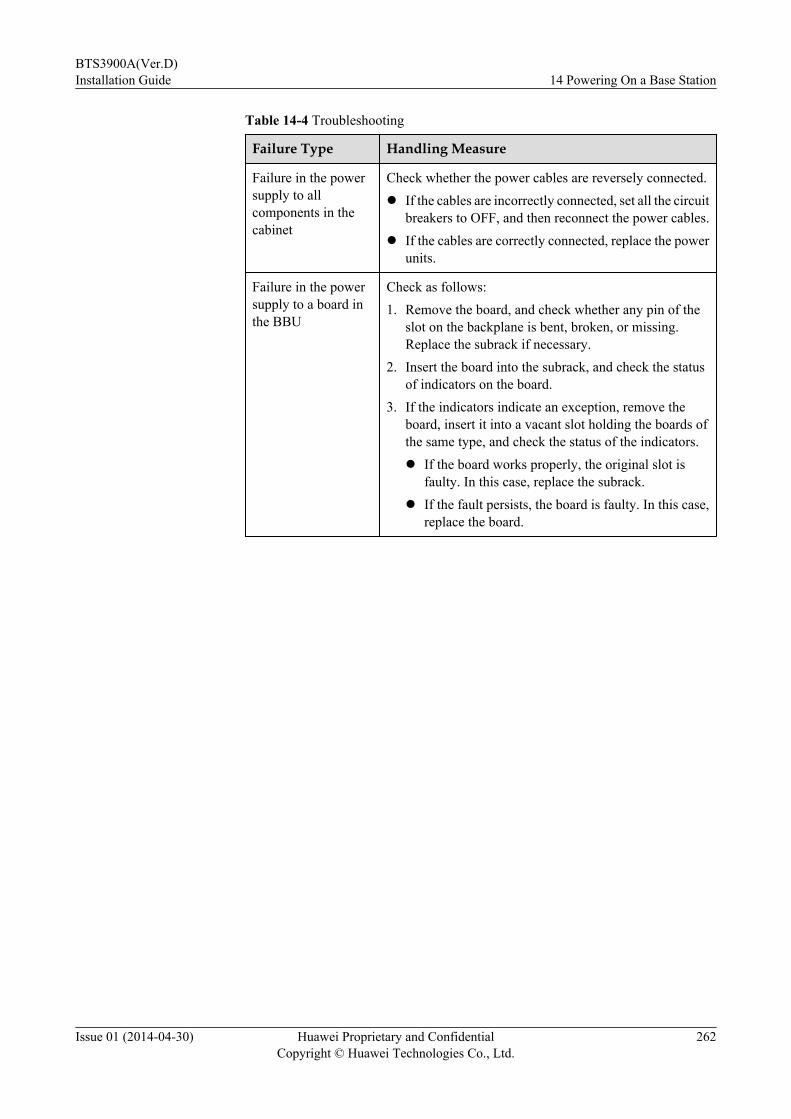
Table 14-4 Troubleshooting
Failure Type Handling Measure
Failure in the powersupply to allcomponents in thecabinet
Check whether the power cables are reversely connected.l If the cables are incorrectly connected, set all the circuit
breakers to OFF, and then reconnect the power cables.l If the cables are correctly connected, replace the power
units.
Failure in the powersupply to a board inthe BBU
Check as follows:1. Remove the board, and check whether any pin of the
slot on the backplane is bent, broken, or missing.Replace the subrack if necessary.
2. Insert the board into the subrack, and check the statusof indicators on the board.
3. If the indicators indicate an exception, remove theboard, insert it into a vacant slot holding the boards ofthe same type, and check the status of the indicators.l If the board works properly, the original slot is
faulty. In this case, replace the subrack.l If the fault persists, the board is faulty. In this case,
replace the board.
BTS3900A(Ver.D)Installation Guide 14 Powering On a Base Station
Issue 01 (2014-04-30) Huawei Proprietary and ConfidentialCopyright © Huawei Technologies Co., Ltd.
262
Failure Type Handling Measure
Failure in the powersupply to othercomponents in thecabinet
Check as follows:1. Check whether the indicator on the fuse terminal block
that connects power supply to the component is on. Skipthis step and go to step 2 if this component does not useany fuse terminal block.l If the indicator on the fuse terminal block is on, the
fuse is faulty. In this case, replace the fuse accordingto the instructions in Replacing a Fuse.
l If the indicator on the fuse terminal block is off, goto step 2.
2. Use a multimeter to measure the input power to thecomponent.l If the input power is normal, replace the component.l If the input power is abnormal, check whether the
power cable for the component is connectedsecurely. If the power cable is not securelyconnected, turn off the circuit breaker for thecomponent (if there is no circuit breaker for thecomponent, remove the connector from the powerunit) and reconnect the power cable. If the powercable is securely connected, the protector (such ascircuit breaker or fuse) on the component may bedamaged. In this case, replace the damagedprotector. If the protector cannot be replaced,replace the upper-level power distributioncomponent.
l Power on a DC base station.
1. Use a multimeter to measure the resistance between the external power supply andthe ground to ensure that there is no short circuit.
2. Turn on the external power switch to power on the RFC cabinet. Power on theTMC11H if it is configured as a transmission cabinet.
3. Optional: Set the circuit breakers connected to loads on the DCDU in the RFC to ON.Skip this step if there is no power circuit breaker on the DCDU, such as DCDU-12Aand DCDU-12B.
4. Optional: Set the circuit breakers connected to loads on the DCDU in the TMC11Hto ON. Skip this step if there is no power circuit breaker on the DCDU, such asDCDU-12C.
5. Set the circuit breaker on the UPEU in the BBU to ON.6. Check the power supply to each component according to the following table.
BTS3900A(Ver.D)Installation Guide 14 Powering On a Base Station
Issue 01 (2014-04-30) Huawei Proprietary and ConfidentialCopyright © Huawei Technologies Co., Ltd.
263
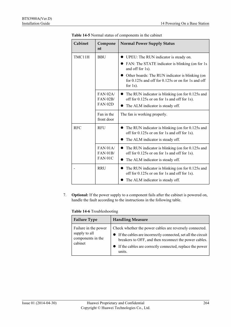
Table 14-5 Normal status of components in the cabinet
Cabinet Component
Normal Power Supply Status
TMC11H BBU l UPEU: The RUN indicator is steady on.l FAN: The STATE indicator is blinking (on for 1s
and off for 1s).l Other boards: The RUN indicator is blinking (on
for 0.125s and off for 0.125s or on for 1s and offfor 1s).
FAN 02A/FAN 02B/FAN 02D
l The RUN indicator is blinking (on for 0.125s andoff for 0.125s or on for 1s and off for 1s).
l The ALM indicator is steady off.
Fan in thefront door
The fan is working properly.
RFC RFU l The RUN indicator is blinking (on for 0.125s andoff for 0.125s or on for 1s and off for 1s).
l The ALM indicator is steady off.
FAN 01A/FAN 01B/FAN 01C
l The RUN indicator is blinking (on for 0.125s andoff for 0.125s or on for 1s and off for 1s).
l The ALM indicator is steady off.
- RRU l The RUN indicator is blinking (on for 0.125s andoff for 0.125s or on for 1s and off for 1s).
l The ALM indicator is steady off.
7. Optional: If the power supply to a component fails after the cabinet is powered on,
handle the fault according to the instructions in the following table.
Table 14-6 Troubleshooting
Failure Type Handling Measure
Failure in the powersupply to allcomponents in thecabinet
Check whether the power cables are reversely connected.l If the cables are incorrectly connected, set all the circuit
breakers to OFF, and then reconnect the power cables.l If the cables are correctly connected, replace the power
units.
BTS3900A(Ver.D)Installation Guide 14 Powering On a Base Station
Issue 01 (2014-04-30) Huawei Proprietary and ConfidentialCopyright © Huawei Technologies Co., Ltd.
264
Failure Type Handling Measure
Failure in the powersupply to a board inthe BBU
Check as follows:1. Remove the board, and check whether any pin of the
slot on the backplane is bent, broken, or missing.Replace the subrack if necessary.
2. Insert the board into the subrack, and check the statusof indicators on the board.
3. If the indicators indicate an exception, remove theboard, insert it into a vacant slot holding the boards ofthe same type, and check the status of the indicators.l If the board works properly, the original slot is
faulty. In this case, replace the subrack.l If the fault persists, the board is faulty. In this case,
replace the board.
Failure in the powersupply to othercomponents in thecabinet
Check as follows:1. Check whether the indicator on the fuse terminal block
that connects power supply to the component is on. Skipthis step and go to step 2 if this component does not useany fuse terminal block.l If the indicator on the fuse terminal block is on, the
fuse is faulty. In this case, replace the fuse accordingto the instructions in Replacing a Fuse.
l If the indicator on the fuse terminal block is off, goto step 2.
2. Use a multimeter to measure the input power to thecomponent.l If the input power is normal, replace the component.l If the input power is abnormal, check whether the
power cable for the component is connectedsecurely. If the power cable is not securelyconnected, turn off the circuit breaker for thecomponent (if there is no circuit breaker for thecomponent, remove the connector from the powerunit) and reconnect the power cable. If the powercable is securely connected, the protector (such ascircuit breaker or fuse) on the component may bedamaged. In this case, replace the damagedprotector. If the protector cannot be replaced,replace the upper-level power distributioncomponent.
----End
BTS3900A(Ver.D)Installation Guide 14 Powering On a Base Station
Issue 01 (2014-04-30) Huawei Proprietary and ConfidentialCopyright © Huawei Technologies Co., Ltd.
265

15 Subsequent Operations
About This Chapter
This chapter describes the operations that need to be performed after the installation, whichinclude sealing the cable holes on the base of the cabinet and repainting the cabinet.
15.1 Sealing the Cable HolesAfter all cables are installed, seal all cable holes on the cabinets and bases.
15.2 RepaintingThe paint on the surface of the cabinet should be kept intact. Therefore, any damaged paint mustbe repaired.
BTS3900A(Ver.D)Installation Guide 15 Subsequent Operations
Issue 01 (2014-04-30) Huawei Proprietary and ConfidentialCopyright © Huawei Technologies Co., Ltd.
266
15.1 Sealing the Cable HolesAfter all cables are installed, seal all cable holes on the cabinets and bases.
Procedurel Seal the cable holes in the cabinet.
1. Route cables through the cable bags and pull the drawstrings to fasten the bags aroundthe cables, as shown in the following figure.
NOTE
l All cables must be bound to the cable bridges on one side of the cabinet.
l You can put your hands in the cable bag to help routing cables through the bag.
l The following figure describes the method of fastening cable bags in an APM30H. Thesame method is used for fastening the cable bags in other types of cabinets.
Figure 15-1 Fastening the cable bags
l Sealing the Cable Holes on the Base (APM30H/TMC11H/IBBS200D/IBBS200T/RFC)
1. Use baffle plates to block redundant space in the cable holes and tighten the two screwsand two butterfly nuts to 1.2N·m (10.62lbf·in.), as shown in the following figure.
BTS3900A(Ver.D)Installation Guide 15 Subsequent Operations
Issue 01 (2014-04-30) Huawei Proprietary and ConfidentialCopyright © Huawei Technologies Co., Ltd.
267

Figure 15-2 Sealing the cable holes on the base
(1) Baffle plate on the right (2) Baffle plate at the rear (3) Baffle plate on the left
2. Use fireproof mud to seal the cable holes on the base, as shown in the following figure.
NOTICEFireproof mud is used only for sealing cable holes on the base. Do not use fireproofmud to seal any cable holes in the cabinet.
BTS3900A(Ver.D)Installation Guide 15 Subsequent Operations
Issue 01 (2014-04-30) Huawei Proprietary and ConfidentialCopyright © Huawei Technologies Co., Ltd.
268

Figure 15-3 Using fireproof mud to seal the cable holes on the base
(1) Fireproof mud (2) PVC corrugated pipe
3. Tighten the three screws on the cover plate in front of the base to 1.2 N·m (10.62
lbf·in.) to secure the cover plate.l Sealing the Cable Holes on the Base (IBBS700D or IBBS700T)
1. Use baffle plates to fill the empty space in the cable holes, as shown in the followingfigure.
2. Install the front cover plate for the base. Tighten the three M6 countersunk screws onthe cover plate to 3 N·m (26.55 lbf·in.), as shown in the following figure.
BTS3900A(Ver.D)Installation Guide 15 Subsequent Operations
Issue 01 (2014-04-30) Huawei Proprietary and ConfidentialCopyright © Huawei Technologies Co., Ltd.
269

Figure 15-4 Sealing the cable holes on the base of the IBBS700D or IBBS700T
(1) PVC corrugated pipe (2) Baffle plate (3) Front cover plate
----End
15.2 RepaintingThe paint on the surface of the cabinet should be kept intact. Therefore, any damaged paint mustbe repaired.
PrerequisitesBefore repainting the cabinet, select the paint of the same color according to the following table.
Table 15-1 Color codes
IntendedObject
Color Huawei Code International Code
Cabinet RAL7035 YB026 RAL7035
Base 3010 light gray YB030 Pantone 422U
BTS3900A(Ver.D)Installation Guide 15 Subsequent Operations
Issue 01 (2014-04-30) Huawei Proprietary and ConfidentialCopyright © Huawei Technologies Co., Ltd.
270

Procedure
Step 1 If the area where the paint is damaged is dirty or the material is rusted, slightly rub the area withsandpaper to remove the dirt or rust, as shown in the following figure.
Figure 15-5 Rubbing the damaged area with sandpaper
Step 2 Use anhydrous alcohol to dampen a cloth and use the wet cloth to remove dirt or dust from therubbed area or the area to be repaired. Then dry the area with another clean cloth, as shown inthe following figures.
Figure 15-6 Cleaning the damaged area with anhydrous alcohol
Step 3 Paint the surface of the cabinet with paint of the same color.
Step 4 Shake the bottle of the paint, open the bottle, and saturate the brush with the paint. Then applythe paint evenly to the damaged area until no scar can be observed, as shown in the followingfigures.
NOTICEThe paint coating should be as thin as possible. No drops are allowed on the paint coating, andthe surface should be smooth.
BTS3900A(Ver.D)Installation Guide 15 Subsequent Operations
Issue 01 (2014-04-30) Huawei Proprietary and ConfidentialCopyright © Huawei Technologies Co., Ltd.
271
Figure 15-7 Repaint the damaged paint coating of the cabinet
Step 5 Perform the following operations after the repaired paint coating has been exposed in the air for30 minutes.
NOTE
The color of the repaired paint coating area should be consistent with that of the surrounding areas, withoutobvious edges and bulges, and the original damage should no longer be distinguishable. In addition, thereshould be no paint peeled off.
----End
BTS3900A(Ver.D)Installation Guide 15 Subsequent Operations
Issue 01 (2014-04-30) Huawei Proprietary and ConfidentialCopyright © Huawei Technologies Co., Ltd.
272