BTERM II -- 5” Gun Launched Projectile · BTERM II -- 5” Gun Launched Projectile ......
22
1 BTERM II -- 5” Gun Launched Projectile 44 th Annual Gun & Missile Systems Conference and Exhibition 8 April 2009 Michael Lukas Naval Surface Warfare Center Dahlgren Division Dahlgren VA [email protected] 540-653-8294 DISTRIBUTION STATEMENT A. Approved for public release; distribution is unlimited. Approved by Michael A. Till, Engagement Systems Department Deputy Department Head
Transcript of BTERM II -- 5” Gun Launched Projectile · BTERM II -- 5” Gun Launched Projectile ......
DISTRIBUTION STATEMENT A
DISTRIBUTION STATEMENT A
1
BTERM II -- 5” Gun Launched Projectile44th Annual Gun & Missile Systems
Conference and Exhibition
8 April 2009
Michael LukasNaval Surface Warfare Center Dahlgren Division
Dahlgren [email protected]
540-653-8294
DISTRIBUTION STATEMENT A. Approved for public release; distribution is unlimited.
Approved by Michael A. Till,Engagement Systems Department
Deputy Department Head
DISTRIBUTION STATEMENT A
DISTRIBUTION STATEMENT A
2
Agenda
• System Overview• Major Subsystems
– Rocket Motor– Low Cost Guidance Electronic Unit (LCGEU)– Canard Actuation System– Warhead
• Recent Tests• Program Accomplishments

DISTRIBUTION STATEMENT A
DISTRIBUTION STATEMENT A
3
Ballistic Trajectory Extended RangeMunition (BTERM)
• Flies a primarily ballistic path, correcting for– Gun pointing errors– Winds aloft
• Compatible with MK45 Mod2 and Mod4 guns• Technology demonstration effort funded by the
Navy• Proven success in boosted and un-boosted guided
flight tests

DISTRIBUTION STATEMENT A
DISTRIBUTION STATEMENT A
4
BTERM Mission Profile
Boosted Ballistic
BTERM
BoostGlide

DISTRIBUTION STATEMENT A
DISTRIBUTION STATEMENT A
5
System Overview
• Boost-Ballistic Trajectory - Long Range, Fastest Flight to Target• Rolling Airframe with Single-Axis Control – Small Delivery Errors• Rear Obturation – Simple, Robust Rocket Motor• High-Density Frag Warhead – Lethal Across Target Set• GPS with Anti-Jam – Short Time in Jammed Zone• MEMS Accelerometers/Rate Sensors – Low Cost, Rugged• Compatible with any gun modified for precision projectiles – MOD2 and MOD4
Fuze• Gun Interface• Safe Separation• HOB Sensor
CAS (Control Actuator System)• COTS Servo Motor• Battery Pack (8 Storage Batteries)• Canard Deployment Mechanism
GEU (Guidance Electronics Unit)• ISA (Inertial Sensor Assembly)• GPS Module/Anti-Jam Module• Flight Processor Module• PCE (Power Conditioning Electronics) and I/O
Fragmenting Warhead• Warhead• PBXN-9 Explosive• Warhead S&A (Safe & Arm)• Booster Cup and Detonator
Rocket Motor• End-Burning with Centerport Inhibitor• SAA-139 Propellant• Titanium Beta-C Rocket Motor Case
TFA (Tail Fin Assembly)• Blast Tube/Rocket Motor Nozzle• ISD (Ignition Safety Device)• 8 Taper Fins• Fin Locking Mechanism

DISTRIBUTION STATEMENT A
DISTRIBUTION STATEMENT A
6
Rocket Motor
• Many subsystems on BTERM II had been proven during BTERM I and ANSR which were predecessors to BTERM II
• Changes were implemented in the manufacturing processes towards a more producible design
• The rocket motor was a pacing factor that required significant and unplanned attention
• Two areas were improved over a 2 year span and ultimately provensuccessful– Over pressure during testing– Nozzle burn-through

DISTRIBUTION STATEMENT A
DISTRIBUTION STATEMENT A
7
BTERM II Rocket Motor Summary
• BTERM II motors have exhibited two different anomalies– Over pressurization– Blast tube insulation burn through
• These only occurred in flight or spin tests, not static– Anomalies are associated with unanticipated interaction between environments and process/material variabilities or design margins
• Overpressurization can be caused by:– Excess propellant surface area– Nozzle area reduction/blockage– Change in propellant combustion properties
• Testing and analysis quickly reduced the cause to excess surface area– Manufacturing techniques were modified – Rocket motor burn was consistent

DISTRIBUTION STATEMENT A
DISTRIBUTION STATEMENT A
8
Performance Predictions – Pressure vs. Time
0.0
0.5
1.0
1.5
2.0
2.5
3.0
3.5
0 5 10 15 20 25 30
TIME (sec)
PR
ESS
UR
E (k
psia
)
RMSS-4A Static Spin Firing at +75F
RMSS-4A Postfire Prediction at +75F
GFT-3D Prefire Prediction at +75F
GFT-3C Prefire Prediction at +75F

DISTRIBUTION STATEMENT A
DISTRIBUTION STATEMENT A
9
Nozzle Improved to Provide Thermal Margin
Nozzle Insulation Improvements– Conducted detailed review with
NSWCDD on 01 Jun 06• Agreement on changes & test
plan• Team agreed on a material fiber
orientation changes to approach and blast tube to resist erosion
– Approach thickness changed to better resist charring / heat
– Spinning static fire tests validated changes
• Erosion analysis added confidence
Fiber orientation
changes
Joint moved aft to avoid turbulent
area
Thickness change

DISTRIBUTION STATEMENT A
DISTRIBUTION STATEMENT A
10
• Developed by Draper Laboratory– Navy funded– Originally developed as risk reduction for ERGM– Rockwell-Collins SAASM GPS receiver
•Direct-Y acquisition
• Survives and operates in gun environments > 10,000 g’s
• Deep Integration GPS anti-jam algorithms– Allows inexpensive commercial MEMSgyros and accels
• Proven success and robustness in laboratory and live fire tests
– Multiple platforms
• Guidance control laws are robust to system errors
Low Cost Guidance Electronic Unit (LCGEU)
PCE & I/O Module
Anti-Jam Electronics Processor
Module
GPS Receiver
ISA
Cover
BTERM II Low Cost Guidance Electronics Unit is a Mature Demonstrated Design

DISTRIBUTION STATEMENT A
DISTRIBUTION STATEMENT A
11
CAS Configuration and Performance History
• Current design proven in flight tests
• Robustness demonstrated in GFT301-1C
• Added current limit to protect battery from over-current
• Improved design for interconnect to GS and Fuze sections
• Optional Al or Steel clam shells
• Proven battery pack in numerous flight tests
Canard
Fuze ConnectorGEU-CAS connector
Clam Shell
DISTRIBUTION STATEMENT A
DISTRIBUTION STATEMENT A
12
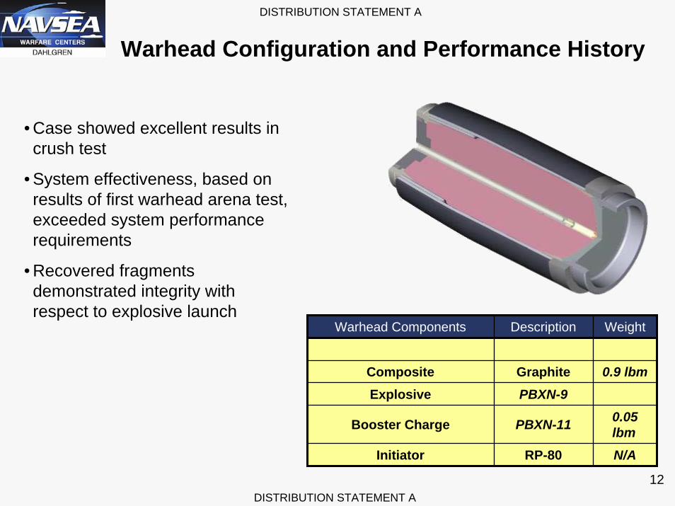
Warhead Configuration and Performance History
Warhead Components Description Weight
Composite Graphite 0.9 lbm
0.05 lbmN/A
Explosive PBXN-9
Booster Charge PBXN-11
Initiator RP-80
• Case showed excellent results in crush test
• System effectiveness, based on results of first warhead arena test, exceeded system performance requirements
• Recovered fragments demonstrated integrity with respect to explosive launch

DISTRIBUTION STATEMENT A
DISTRIBUTION STATEMENT A
13
Guided Flight Results
• GUFT-1– February 2006– Guided Unboosted Flight Test– 8.7nmi@ Yuma Proving Grounds-> 7.3nmi sea level– 5 foot miss distance from target
• GFT-301– September 2008– Guided Flight Test– 54nmi@ White Sands Missile Range-> 49nmi sea level– 15 foot miss distance from target

DISTRIBUTION STATEMENT A
DISTRIBUTION STATEMENT A
14
GUFT-1 Mission Overview
4.960 @ Body4.986 @ Bore rider
FuzeRocket MotorMass Simulator GEU
CASTelemetry
Tail Fin Ass’y
Test:• Location: Yuma Proving Ground (YPG)• Test dates – 08 February 2006
Test Conditions:• 5”/62 Caliber Gun (S/N 17499)• NACO Propellant Charges• Muzzle Velocity = 2,170 ft/sec• Expected Launch Accel = 7,200 G• GUFT-1/ODT QE = 60.5°
Test Configurations:• 3 Baseline Obturated TCD Slugs• 1 Guided, Unboosted Flight Test (GUFT-1)
Instrumentation:• 3 M11 and 2 Piezoelectric Pressure Sensors
within Propelling Charges• Barrel Pressure Data• Camera Coverage at Gun and Target• Trajectory and Muzzle Radar• Telemetry for GUFT-1

DISTRIBUTION STATEMENT A
DISTRIBUTION STATEMENT A
15
February 8, 2006 Guided Unboosted Results

DISTRIBUTION STATEMENT A
DISTRIBUTION STATEMENT A
16
Guided flight observed from radar track
GUFT-1 Mission Objective Results
• New mag based down determination successful
• GPS acquisition successful
• Canard deployment successful
• Canard control successful
• Hit the TARGET!
TM shows canard Response tracking command very well
Test Objective Criteria Results
Evaluate short range GNC algorithms
Successful acquisition of telemetry and radar data
Passed
Demonstrate CAS performance with COTS actuator
COTS actuator demonstrates the ability to control the flight trajectory using commands issued by the GEU
Passed
1.5m impact instead of 185m ballistic miss1.5m impact instead of 185m ballistic miss
DISTRIBUTION STATEMENT A
DISTRIBUTION STATEMENT A
17
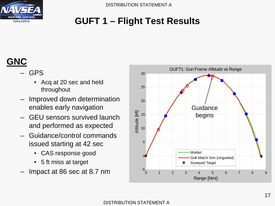
GUFT 1 – Flight Test Results
GNC– GPS
• Acq at 20 sec and held throughout
– Improved down determination enables early navigation
– GEU sensors survived launch and performed as expected
– Guidance/control commands issued starting at 42 sec
• CAS response good• 5 ft miss at target
– Impact at 86 sec at 8.7 nm 0 1 2 3 4 5 6 7 8 9-5
0
5
10
15
20
25
30GUFT1: Gun Frame Altitude vs Range
Range [Nmi]
Alti
tude
[kft]
WeibelGuft Match Sim (Unguided)Surveyed Target
Guidancebegins

DISTRIBUTION STATEMENT A
DISTRIBUTION STATEMENT A
18
GFT-301 Mission Overview
Test:• Location: White Sands Missile Range
(WSMR) – Site L531• Test Date – 29 Sep 2008
Test Conditions:• 5”/62 Caliber Gun (S/N 17499)• NACO Propellant Charges• Muzzle Velocity = 2170 ft/sec• Expected Launch Accel = 7200g• Projectiles QE ~ 59.3°• GFT-301 long range ~ 54 nmi
Test Configurations:• 2 TCD Slugs + 1 backup• 2 GFT-3 Guided, Boosted Flight Test• 1 EET-3 Guided, Boosted Flight Test
Instrumentation:• 3 M11 and 2 Piezoelectric Pressure Sensors
within Propelling Charges• Barrel Pressure Data• Camera Coverage @ Gun & Targets• Trajectory & Muzzle Radar• ATK Telemetry

DISTRIBUTION STATEMENT A
DISTRIBUTION STATEMENT A
19
GFT-301 Flight Profile
Guided Flight Test Timeline (Boosted)
1.0 nmi
54.06 nmi
ProjectileFired
0.2 nmi
0.9 sec : Begin Digital Telemetry Data
Ballistic FlightTerminal Guidance
TerminalGuidance
Impact177.8 sec
Rocket Motor Firing
27.62 nmi
0.1 nmi
7.3 nmi
3.0 nmi
6 sec : Begin GPS Aqu. and Down Det
18 sec : Nominal GPS Acquisition
0.6 sec : Power Up Complete
5.9 nmi
34 Sec: Down Det Complete/First Nav.
Solution Ready
7 sec : Rocket Motor Ignition
28.84 sec : Rocket Motor Burnout
92 Sec: Begin Guidance
1.1 nmi

DISTRIBUTION STATEMENT A
DISTRIBUTION STATEMENT A
20
Recent BTERM Success
Target
Impact4.88 m
Altitude (Corr.) vs Range: Comparison
0
20,000
40,000
60,000
80,000
100,000
120,000
0 10 20 30 40 50 60
Range (Nmi)
Alti
tude
(ft)
6-DOFEET-3BGFT-3DGFT-3C
C-Band Last Known Position
49.7
5,876
-5,133
170
48.9
5,336
-6,189
168
54.0
2,940
-77
188
GFT-3C GFT-3D EET-3B6-DOF
Time Of Flight (sec) 178
54.08
2,428
± 15Cross Range (ft)
Range (Nmi)
Altitude (ft)
Cross Range (Corr.) vs Range: Comparison-7,000
-6,000
-5,000
-4,000
-3,000
-2,000
-1,000
0
1,0000 10 20 30 40 50 60
Range (Nmi)C
ross
Ran
ge (f
t)
6-DOFEET-3BGFT-3DGFT-3C
C-Band Last Known Position
49.7
5,876
-5,133
170
48.9
5,336
-6,189
168
54.0
2,940
-77
188
GFT-3C GFT-3D EET-3B6-DOF
Time Of Flight (sec) 178
54.08
2,428
± 15Cross Range (ft)
Range (Nmi)
Altitude (ft)All Three Test Projectiles On VerySimilar Trajectories
GFT-3C Guided To Target
Recent Success Validates 5” Gun Solution for NSFS
Sept 2008 test success• Achieved 54 nmi range
– Full duration rocket motor burn
• 4.9 m miss distance – Acquired 10 satellites in direct Y
– Corrected 5 nmi of range error
– Corrected 0.9 nmi of cross range error
DISTRIBUTION STATEMENT A
DISTRIBUTION STATEMENT A
21
Program Accomplishments
• Demonstrated short and long range guidance accuracy– 8-nmi guided flight test within approximately 5-feet of the intended aim-point
– 54-nmi guided flight test within approximately 15 feet of the intended aim point
– Low Cost Guidance Electronics Unit (LCGEU) continues to demonstrate robust performance meeting all requirements
– 6-DOF simulation accurately predicts actual guidance performance
– CAS (w/COTS components) provides sufficient control authority to meet guidance accuracy requirements
– Tail fin deployment and locking
– Electronic ISD demonstrated

DISTRIBUTION STATEMENT A
DISTRIBUTION STATEMENT A
22
• Demonstrated subsystems
– Guidance, navigation and control subsystem and algorithms– Composite blast fragment warhead – Single Axis CAS including the COTS actuator – Electronic Ignition Safety Device– Reliable rocket motor performance
• Demonstrated lethality of warhead – Arena tests at NSWC-DD demonstrated lethality meets or exceeds requirements
against the ERM target set– Actual performance better than simulation/model– Crush test demonstrated strength exceeds requirement for BTERM launch
environment of ~7500-g
• Demonstrated the data communications interface (DCI)– Benchtop tests with ERM setter
Program Accomplishments