BTECHN PROJECT 2 Final report (GROUP)
29
SCHOOL OF ARCHITECTURE, BUILDING & DESIGN Modern Architecture Studies in Southeast Asia (MASSA) Research Unit Bachelor of Science (Honours) (Architecture) BUILDING TECHNOLOGY 1 [ARC 3512] Project 2 – Advanced Roof & Industrialized Building System Name ID. NO Lee Yiang Siang 0302966 Celine Tan Jean Inn 0303669 Ling Teck Ong 0303127 Poh Wei Keat 0303646 Wong Soon Fook 0302953 Chung Ka Seng 0316922 Azin Eskandari 0312234 1
-
Upload
ong93 -
Category
Technology
-
view
861 -
download
8
Transcript of BTECHN PROJECT 2 Final report (GROUP)

SCHOOL OF ARCHITECTURE, BUILDING & DESIGNModern Architecture Studies in Southeast Asia (MASSA)
Research Unit
Bachelor of Science (Honours) (Architecture)
BUILDING TECHNOLOGY 1 [ARC 3512]
Project 2 – Advanced Roof & Industrialized Building System
Name ID. NO
Lee Yiang Siang 0302966
Celine Tan Jean Inn 0303669
Ling Teck Ong 0303127
Poh Wei Keat 0303646
Wong Soon Fook 0302953
Chung Ka Seng 0316922
Azin Eskandari 0312234
1

Table of Content:
1.0 INTRODUCTION ……………………………………………………………………………….... 2
2.0 ROOF CONSTRUCTION2.1 COATED FIBRE GLASS MEMBRANE (PTFE) ………………………………………..... 3-5
2.2 STRUCTURAL DESIGN…………………………………………………………………..... 6-7 2.3 ROOF SPECIFICATIONS…………………………………………………………………………….... 8-9
3.0 INDUSTRIALIZED BUILDING SYSTEM3.1 PRECAST REINFORCED CONCRETE WALL………………………………………………..... 10-14
3.2 PRECAST REINFORCED CONCRETE BEAM &COLUMN…………………............... 15-193.3 PRECAST REINFORCED CONCRETE FLOORING (Hollow Core Slab)…............ 20-253.4 PRECAST REINFORCED CONCRETE STAIRCASE……………………………………...... 26-28
4.0 REFERENCES…………………………………………………………………............................. 29
2

Full Name : Olympiastadion BerlinLocation : Westend, Charlottenburg-
Wilmersdorf, Berlin, GermanyOwner :Olympiastadion Berlin GmbHArchitect :Werner March/Albert Speer &
Friedrich Wilhelm KraheBuilt :1934 to 1936Opened : 1936Capacity : 74,064Field size : 105 × 68 m
The Olympic Stadium in Berlin has been designed by the architect Werner March for the Olympic Games from1933 and is the largest stadium in Germany. The construction is listed as protected monuments. The stadiumoval is interrupted by the Marathon gate allowing the Bell tower to be seen from inside the stadium. The ovalis 300 m long, 215 m wide and the grandstand has a maximum height of 15 m above the surrounding ground.The upper and lower terraces are separated by a inner gallery. The grandstand was built with precastreinforced concrete (prefabricated step units and precast radial frames). The columns of the outer and theinner galleries are made of stone blocks.
Figure 1.1 Panorama View of Berlin Olympic Stadium
Figure 1.2 Demolition and reconstruction of lower ring, renovation and alterations to upper ring
Figure 1.3 Floor Plan of Berlin Olympic Stadium
Olympiastadion Berlin1.0 INTRODUCTION
3

Structural Members of Berlin Olympic StadiumThere are tubular radial and tangential truss girderswith welded nodes and 76 radial truss girders, onefor every two stone facade columns. They are twovertical flange trusses and are carried by twotangential members: a spatial, three-flange trusssustained by the tree dinner columns and an outerspatial beam sustained by the outer columns. At theside of the roof in the vicinity of the joint betweenthe membrane and the glass surfaces there is aninclined two-flange truss, which has the role ofequalizing the vertical displacements at the ends ofthe radial girders. In between the describedmembers there are tangential tubular bars linkingthe upper nodes of the radial girders andrespectively the lower nodes. Their role is to stabilizethe radial girders by carrying the horizontaltangential forces to the bracing. The curved lowerflange of the radial truss is stabilized vertically bymeans of a steel cable.
The Olympiastadion was partly covered for the first time. A roof existing of steel and Plexiglas was added on the main tribunes. At that time, these were modern and light materials and gave the stadium a completely new look.
Figure 1.4 Views of the stadium without roof (a) and with the new roof (b)
Figure 1.5 The upper membrane.
Figure 1.6 The lower membrane. (View inside the roof box)
Compartment of RoofThe upper membrane is supported by steelarches and has a double negative curvature.The lower membrane is open on theperimeter, plane and pre-stressed by meansof small springs
Before After
4

Sectional Perspective View
Rows of Seating Chairs in Stadium Interior View showing Precast Concrete Column
Section View of the PrecastConcrete Structure
Advanced Roof Membrane Structure Column Supporting the Roof
Olympiastadion Berlin
5
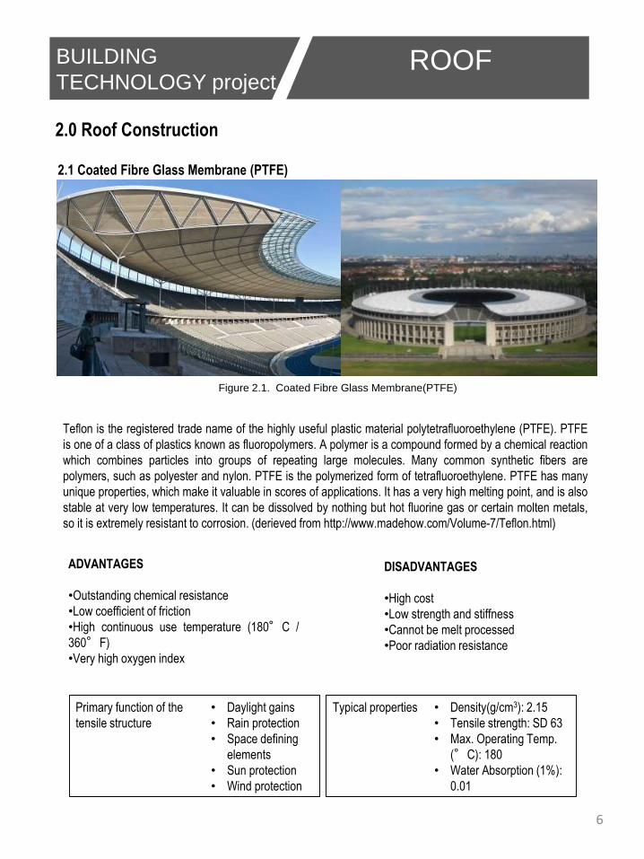
2.1 Coated Fibre Glass Membrane (PTFE)
2.0 Roof Construction
Figure 2.1. Coated Fibre Glass Membrane(PTFE)
Teflon is the registered trade name of the highly useful plastic material polytetrafluoroethylene (PTFE). PTFE
is one of a class of plastics known as fluoropolymers. A polymer is a compound formed by a chemical reaction
which combines particles into groups of repeating large molecules. Many common synthetic fibers are
polymers, such as polyester and nylon. PTFE is the polymerized form of tetrafluoroethylene. PTFE has many
unique properties, which make it valuable in scores of applications. It has a very high melting point, and is also
stable at very low temperatures. It can be dissolved by nothing but hot fluorine gas or certain molten metals,
so it is extremely resistant to corrosion. (derieved from http://www.madehow.com/Volume-7/Teflon.html)
Primary function of the
tensile structure
• Daylight gains
• Rain protection
• Space defining
elements
• Sun protection
• Wind protection
ADVANTAGES
•Outstanding chemical resistance
•Low coefficient of friction
•High continuous use temperature (180°C /
360°F)
•Very high oxygen index
DISADVANTAGES
•High cost
•Low strength and stiffness
•Cannot be melt processed
•Poor radiation resistance
Typical properties • Density(g/cm3): 2.15
• Tensile strength: SD 63
• Max. Operating Temp.
(°C): 180
• Water Absorption (1%):
0.01
6
BUILDING
TECHNOLOGY project 2ROOF

2.2 Structural Design
Figure 2.2 Detail from the computational model
of the structure
TOPIC
The structural system and components are depicted in Fig. 2.2.
1.There are tubular radial and tangential truss girders with
welded nodes.
2.There are 76 radial truss girders, i.e. one for every two stone
facade columns.
3.They are vertical two-flange trusses and are carried by two
tangential members: a spatial, three-flange truss sustained by
the treed inner columns and an outer spatial beam sustained
by the outer columns.
4.At the side of the roof in the vicinity of the joint between the
membrane and the glass surfaces there is an inclined two-
flange truss to equalize the vertical displacements at the ends
of the radial girders.
5.In between the described members there are tangential
tubular bars linking the upper nodes of the radial girders and
respectively the lower nodes to stabilize the radial girders by
carrying the horizontal tangential forces to the bracing.
6.The curved lower flange of the radial truss is stabilized
vertically by means of a steel cable (see Fig.2.2).
The textile membranes were designed by the consultant civil engineers
Schlaich, Bergermann and Partners . The upper membrane is supported
by steel arches and has a double negative curvature (Fig. 2.3(a)). The
lower membrane is open on the perimeter, plane and pre-stressed by
means of small springs (Fig. 2.3(b)). A detailed description of the roof
construction is given in.
Following German companies were involved with the design and erection
of the roof: von Gerkan, Marg and Partners (gmp) as architects, Krebs &
Kiefer Consulting Engineers Ltd as structural engineers, Schlaich
Bergermann and Partners as designer of the membrane roofing and of
some cast nodes, Wacker Engineers and Institute for Industry
Aerodynamic Aachen for the Wind Engineering, Institute of Steel
Construction (University of Aachen) as expert for special steel, Dillinger
Stahlbau Ltd for the steel construction, B&O Hightex Ltd for the
membrane construction, MERO Ltd for the glass construction and Prof.
M. Specht as proof engineer. For the design of the roof gmp and Krebs &
Kiefer have received the Special Award of the German Association of
Steel Construction 2004.
Figure 2.3 (a) The upper membrane
Figure 2.3 (b) The lower membrane
(view inside the roof box)
7
BUILDING
TECHNOLOGY project 2 ROOF

2.3 Roof Specifications
Figure 2.3 Roof membrane view from interior
Roof construction
Total roof area: ca. 42.000m²
•Upper roof membrane: approx. 27.000m², distributed to 77
sectors
•Lower roof membrane: approx. 28.000m²
•Glass surface: 6006m²
Material: PTFE-coated glass fiber (PTFE:
Polytetrafluorethylen) Roof width: approx. 68m Distance
roof to infield: 39,99m Roof weight: ca. 3.500t
Number of steel posts inside seating area: 20 with the
distance between posts ranging from 32 to 40m and a
length of 8,50m Diameter: bifurcation 35cm, pedestal
26cm Number of outside posts: 132 Binders: 76 Material:
Steel St 52 and St 37
Construction
The erection of the steel structure has always
started at a radius with inner column. Following
steps were used. Firstly came the outer columns
and the steel and pre-cast R/C elements of the
perimeter beam. The inner column was then erected
and temporarily supported. Afterwards the assembly
made by the parts of the radial trusses adjacent to
the inner column and lying between this column and the outer beam was erected. All spatial parts were welded
outside the stadium and were already equipped with the steel arches, which had to carry the upper textile
membrane (Fig.2.4). At this stage the structure became self stabilized, there was no longer need for the
temporary support of the inner column.
After ballasting of the outer beam the erection
continued with the tangential spatial truss linking the
inner columns, the rests of the radial and tangential
steel structure and so on.
Fgure 2.4 Erection of the steel structure
Figure 2.5 Detail of the outer beam before ballasting 8
BUILDING
TECHNOLOGY project 2 ROOF

9
BUILDING
TECHNOLOGY project 2ROOF
Figure 2.6 Detail of the truss system
Figure 2.7 Detail of the steel truss systemFigure 2.8 Detail of structural steel frame
Figure 2.9b Detail of the tension rope connect to the membrane
Figure 2.9a Detail of connection of tension rope
with truss system

Precast reinforced concrete wall panels can take many forms. It consist of steel-reinforced concrete ribs
that run vertically and horizontally in the panels. Others are solid precast concrete panels. Panels are
precast and cured in a controlled factory environment so weather delays can be avoided. A typical
panelised foundation can be erected in four to five hours, without the need to place concrete on site for
the foundation. The result is a foundation that can be installed in any climate zone in one sixth of the time
needed for a formed concrete wall.
ADVANTAGES• Ease of installation
• Well manufactured in advance of installation
• Most panels included embedded connections
hardware
• Consistent quality
• Reduced weather dependency
• Environmentally Friendly
• Weather and UV resistance
• Energy Savings
• Modularity
3.1 PRECAST REINFORCED CONCRETE WALL
Figure: Detail drawing of precast reinforced
Figure 3.1 Concrete panels
BUILDING
TECHNOLOGY project 2PRECAST R/C WALL DETAILS
DISADVANTAGES• Connection may be difficult
• Limited building design flexibility
• Joints between panels are often
expensive and complicated
• Skilled workmanship is required
• Camber in beams and slabs
Density - 800 to 1400 kg/m3
STC - 45
Thermal Resistance (R-Value) - 30 degree Celsius/inch
Absorption by Volume, max - <1.8%
Thermal Conductivity (K-Factor) - 23 degree Celsius/ (hr.)
Wall Compressive Strength - 0.23N /mm2
3.0 Industrialised Building System
10

Proper planning and preparation works are required before the actual erection of precast concrete
elements to ensure efficient and quality installation. Items should be carefully planned such as:
• Method and sequence of assembly and erection
• Provide temporary supports
• Provision for final structural connections and joint details
• Handling and rigging requirements
STEP 1:• Set reference line and offset line
• Determine the position of
precast elements to install
INSTALLATION OF PRECAST REINFORCED CONCRETE WALL
Figure 3.1 (a): Setting Out
BUILDING
TECHNOLOGY project 2PRECAST R/C WALL DETAILS
STEP 2:• Lift and rig the panel to its
designated location with the
use of wire ropes
STEP 3:• Prepare and apple non-shrink
mortar to seal the gaps
• Keep the installation panels
undisturbed for 24hours
STEP 4:• The joint between façade walls or between external
columns with beams or wall elements approved sealant
and grout will be installed at later stage
• For panel with welded connection, place the connecting
plate between the panels and carry out welding
• Check that the compressible form
or backer road are properly
secured.
MAINTENANCEAn annual maintenance check should be carried out by a responsible person. Checking all surfaces for any
signs cracks or impact damage.
• Safe storage & Disposal Materials
• Avoid watercourses with material and packaging
• Avoidance of frost
• Store in dry when not required
• Avoid litter
• Remove unused packs from site
• Provide excellent protection against impacts from
explosion, vehicles and projectiles.
• Precast concrete wall panels have passed tornado
/hurricane impact testing
11

Figure 3.1(b) : Berlin Olympic Stadium on precast reinforced stadium panel
BUILDING
TECHNOLOGY project 2PRECAST CONCRETE WALL DETAILS
PRECAST WALL WITH LEED REQUIREMENTS• Optimize energy performance –moderate indoor temperature extremes through thermal mass and
insulation applications.
• Building reuse materials – longer lifespan and can be reused when modifying designs for intended
use.
• Construction waste management – diverting construction debris from landfill disposal by recycling
concrete material.
• Recycled content – supplementary cementations materials, such as fly ash, silica fume and slag.
• Regional materials – use of indigenous materials and reduced transportation distances.
• Low-emitting materials – precast foundation walls, floors and ceilings provide low indoor air
contaminant surfaces. .
• Materials and resource credit – bio-based release agents.
• Innovative design credit – precast can be made to take on any shape, colour or texture.
12

Figure 3.1(c) : Precast Concrete Wall System Detail
BUILDING
TECHNOLOGY project 2PRECAST CONCRETE WALL DETAILS
13

-Panel to panel square external corner (butt joint).-Proprietary composite or thermo-plastic ties should be used between skins. If using steel ties, the effects of thermal bridging should be considered.
Figure 3.1(d) : Example of installation of precast concrete wall at site
Figure 3.1(e) : Joining of panel to panel
Figure 3.1(g) : Example of different type of joining of concrete panel
Figure 3.1(f) : Detail of concrete wall section
BUILDING
TECHNOLOGY project 2PRECAST CONCRETE WALL DETAILS
14

BUILDING
TECHNOLOGY project 2BEAM & COLUMN
Precast concrete beams and columns can be used to create the entire framing system for the shell
of a building. A precast concrete structural system can provide a number of benefits, including speed
of erection, single-source provider for all framing needs, consistent high quality, durable structural
support, fire resistance and others.
Columns: – A column is a vertical member carrying the beam and floor loadings to the foundation.
It is a compression member and therefore the column connection is required to be proper. The main
principle involved in making column connections is to ensure continuity and this can be achieved by
a variety of methods.
Beams: – Beams can vary in their complexity of design and reinforcement from the very simple
beam formed over an isolated opening to the more common encountered in frames where the
beams transfer their loadings to the column. Methods of connecting beams and columns are
A precasting concrete haunch is cast on to the column with a locating dowel or stud bolt to fix the
beam.
A projecting metal corbel is fixed to the column and the beam is bolted to the corbel.
Column and beam reinforcement, generally in the form of hooks, are left exposed. The two
members are hooked together and covered with in-situ concrete to complete the joint. This is as
shown in the figure.
3.2 PRECAST REINFORCED CONCRETE BEAM &COLUMN
15

BUILDING
TECHNOLOGY project 2BEAM & COLUMN
Advantages:
• Saving in cost, material, time & manpower.
• Shuttering and scaffolding is not necessary.
• Installation of building services and finishes can be done immediately.
• Independent of weather condition.
• Components produced at close supervision .so quality is good
• Clean and dry work at site.
• Possibility of alterations and reuse
• Correct shape and dimensions and sharp edges are maintained.
• Very thin sections can be entirely precast with precision.
Disadvantages:
• Handling and transportation may cause breakages of members during the transit and extra
provision is to be made.
• Difficulty in connecting precast units so as to produce same effect as monolithic. This leads to
non-monolithic construction.
• They are to be exactly placed in position, otherwise the loads coming on them are likely to get
changed and the member may be affected.
• Disadvantages:
• High transport cost
• Need of erection equipment
• Skilled labor and supervision is required.
Figure 3.2(a) : Detail of column & beams connection
16

BUILDING
TECHNOLOGY project 2BEAM & COLUMN
Figure 3.2(b) : Dimension of precast concrete column
Figure 3.2(c) : Example of installation of precast column and beam at site
17

BUILDING
TECHNOLOGY project 2BEAM & COLUMN
18

BUILDING
TECHNOLOGY project 2BEAM & COLUMN DRAWING
Figure 3.2(d) : Connection of Precast concrete beam & column
Figure 3.2(e) : Precast concrete column to beam detail
19

Design Benefits
•Flexibility of Design Approach
•Enhanced Spans
Manufacturing Benefits
Factory produced to High Quality
Standard
Preformed Site Services
Construction Benefits
One or two hour fire resistance
Type ‘A’ Finished Soffit
Shelf Angle Bearing
Cast in lifting hooks
Sound resistance – Noise transfer performance
Reduction of in-situ Concrete
Speed of Erection
Immediate un-propped Working Platform
A Hollow core slab offers the ideal structural section by reducing deadweight while providing the
maximum structural efficiency within the slab depth. Precast floors are available with a variety of
factory-formed notches, slots and reinforcement arrangements which offer various design
approaches.
BUILDING
TECHNOLOGY project 2FLOORING
3.3 PRECAST REINFORCED CONCRETE FLOORING (Hollow Core Slab)
Suitable Applications
Stadium
Schools
Retail
Car parks
Office buildings
Leisure & Hotels
Residential (Single and multi-occupancy)
Care homes
Hollow Core Slab Flooring
Section of Olympiastadion Berlin
20

BUILDING
TECHNOLOGY project 2FLOORING
Figure 3.3(a) : Detail of hollow core slab connection
Figure 3.3(b) : Detail of hollow core slab connected to wall
21

BUILDING
TECHNOLOGY project 2FLOORING
Figure 3.3(c) : Hollow Core Floors Unit Profile 22

BUILDING
TECHNOLOGY project 2FLOORING
Figure 3.3(d) : Connection of hollow core flooring to the beam
23

BUILDING
TECHNOLOGY project 2FLOORING
Figure 3.3(f) Plank to plank connection
Figure 3.3(e) : Example of installation of hollow core
slab at site
Figure 3.3(g) Connection of floor with wall 24

BUILDING
TECHNOLOGY project 2FLOORING
25

BUILDING
TECHNOLOGY project 2STAIRCASE
-Concrete stairs offer a fast, efficient and cost effective option, reducing labour on site, being fast to install and providing immediate access to all floor areas.
THE BENEFITS
-FLEXIBLE CONFIGURATIONS WITH THE ABILITY TO MAKE CUSTOM BUILT MOULDS WE CAN ACCOMMODATE A WIDE VARIETY OF STAIRCASE CONFIGURATIONS AND DESIGNS.-INNOVATIVE DESIGN OUR DESIGNERS WORK HARD TO KEEP APACE WITH LATEST CONSTRUCTION TRENDS EG. STAIRS ARE NOW AVAILABLE THAT ACCOMODATE UNDERFLOOR HEATING PIPES.-QUALITY FINISH MANUFACTURED IN A CONTROLLED FACTORY ENVIRONMENT, USING BESPOKE MOULDS GIVES A PREMIUM QUALITY FINISH.-MMEDIATE ACCESS IMPROVES SITE SAFETY AND EFFICIENCY.-EASE OF PROGRAMMING MANUFACTURED OFFSITE AND DELIVERED AND INSTALLED TO MEET YOUR BUILD PROGRAMME.-LANDINGS CAN INCORPORATE ANY DETAIL THAT THE DESIGN DEMANDS SUCH AS CURVES.-LANDINGS CAN BE DETAILED FOR PROGRESSIVE COLLAPSE IF REQUIRED.
3.4 PRECAST REINFORCED CONCRETE STAIRCASE
Figure 3.4(a) Precast concrete staircase
26

BUILDING
TECHNOLOGY project 2STAIRCASE
Figure 3.4(b) Detail of precast concrete staircase
Figure 3.4(d) Dimension of staircaseFigure 3.4(c) Applied finish to the landing area 27

BUILDING
TECHNOLOGY project 2STAIRCASE
Figure 3.4(e) Installation of precast concrete staircase at site
Figure 3.4(f) Detail of precast staircase
Figure 3.4(g) Detail of installation of precast staircase
A stairs is a set of steps orflight leading from one floorto another. It is designed toprovide easy and quick accessto different floors. The stepsof a stair may be constructedas a series of horizontal opentreads with a space betweenthe treads (as in a ladder or afoot-over bridge) or asenclosed steps with a verticalface between the treads,called a riser. The enclosureor part of the buildingcontaining a stairs is calledstaircase.
28

29
4.0 REFERENCES:
Compiled by Legal Research Board. Uniform Building By-Laws 1984, 1997, International Law BookServices, Kuala Lumpur.
CIDB (2014) CIDB Malaysia. Retrieved November 20, 2014, from http://www.cidb.gov.my/cidbv4/index.php?option=com_content&view=article&id=391&Itemid=184&lang=en
Creative (2012) Industrialized Building System. Retrieved November 21, 2014, from http://www.creativeptsb.com/industrialized-building-system-IBS-supplier-Malaysia.htm
Orton, Andrew, 2001, The Way We Build Now: Form Scale and Technique, Spon Press, London. Spon Press