btech thesis
40
OPTIMIZATION OF PROCESS PARAMETERS INVOLVED IN LASER BENDING OPERATION USING TAGUCHI EXPERIMENTAL DESIGN METHOD A Project Report Submitted in Partial Fulfilment of the Requirements for the Degree of B. Tech. (Mechanical Engineering) By PRATOH SOURAV SAHU Roll No. 10603039 Under the supervision of Prof. Saroj Kumar Patel Associate Professor Department of Mechanical Engineering, NIT, Rourkela Department of Mechanical Engineering National Institute of Technology Rourkela MAY, 2010
-
Upload
-supreet-singh -
Category
Documents
-
view
92 -
download
0
description
nit
Transcript of btech thesis
OPTIMIZATION OF PROCESS PARAMETERS INVOLVED IN
LASER BENDING OPERATION USING TAGUCHI
EXPERIMENTAL DESIGN METHOD
A Project Report Submitted in Partial Fulfilment of the Requirements for the Degree of
B. Tech.
(Mechanical Engineering)
By
PRATOH SOURAV SAHU Roll No. 10603039
Under the supervision of
Prof. Saroj Kumar Patel Associate Professor
Department of Mechanical Engineering, NIT, Rourkela
Department of Mechanical Engineering
National Institute of Technology
Rourkela MAY, 2010
National Institute of Technology
Rourkela
C E R T I F I C A T E
This is to certify that the work in this thesis entitled optimization of
process parameters involved in laser bending operation
using Taguchi experimental design method by Pratoh Sourav
Sahu has been carried out under my supervision in partial fulfilment of
the requirements for the degree of Bachelor of Technology in
Mechanical Engineering during session 2009- 2010 in the Department of
Mechanical Engineering, National Institute of Technology, Rourkela.
To the best of my knowledge, this work has not been submitted to any
other University/Institute for the award of any degree or diploma.
Dr. Saroj Kumar Patel
(Supervisor)
Associate Professor
Dept. of Mechanical Engineering
National Institute of Technology
Rourkela - 769008
A C K N O W L E D G E M E N T
It gives me immense pleasure to express my deep sense of gratitude to my supervisor
Prof. Saroj Kumar Patel for his invaluable guidance, motivation, constant
inspiration and above all for his ever co-operating attitude that enabled me in bringing
up this thesis in the present form.
I am extremely thankful to Prof. R. K. Sahoo, Head, Department of Mechanical
Engineering and Prof. K. P. Maity, Course Coordinator for their help and advice
during the course of this work.
I express my sincere gratitude to Mr. Siva Reddy, M. Tech and Prof. S. K. Sahoo for
their invaluable guidance during the course of this work.
I am greatly thankful to all the staff members of the department and all my well
wishers, class mates and friends for their inspiration and help.
DATE: 14-05-2010 PRATOH SOURAV SAHU PLACE: ROURKELA Roll No. - 10603039 8th Semester, B. Tech Mechanical Engineering Department National Institute of Technology Rourkela-769008
A B S T R A C T
A laser-bending process has many advantages such as no mechanical spring-back effect,
precise incremental adjustment, high level of process flexibility, and the capability of
production of complex shapes due to which it has shown a great promise and so has lately
been the subject of considerable interest. This paper reports the variation of bending angle
with change of different process parameters. Experiments are conducted following a well
planned experimental schedule based on Taguchi’s design of experiments (DOE) method and
the optimal values of process parameters for maximum bending angle is thus determined.
Process parameters include laser power, pulse diameter, pulse duration and scan speed.
Significant control factors predominantly influencing the bending angle are also identified.
Specimen used for experiments is Aluminium metal sheet and Nd-YAG laser is used as laser
source.
Keywords: laser bending, spring-back, DOE.
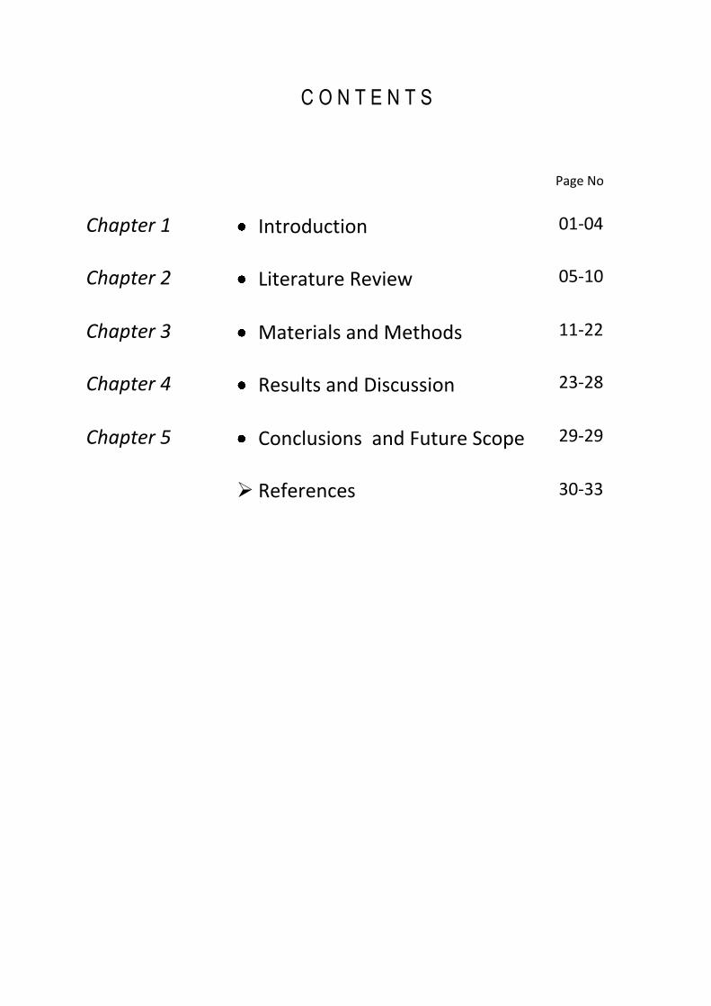
C O N T E N T S
Page No.
Chapter 1 Introduction 01-04
Chapter 2 Literature Review 05-10
Chapter 3 Materials and Methods 11-22
Chapter 4 Results and Discussion 23-28
Chapter 5 Conclusions and Future Scope 29-29
References 30-33
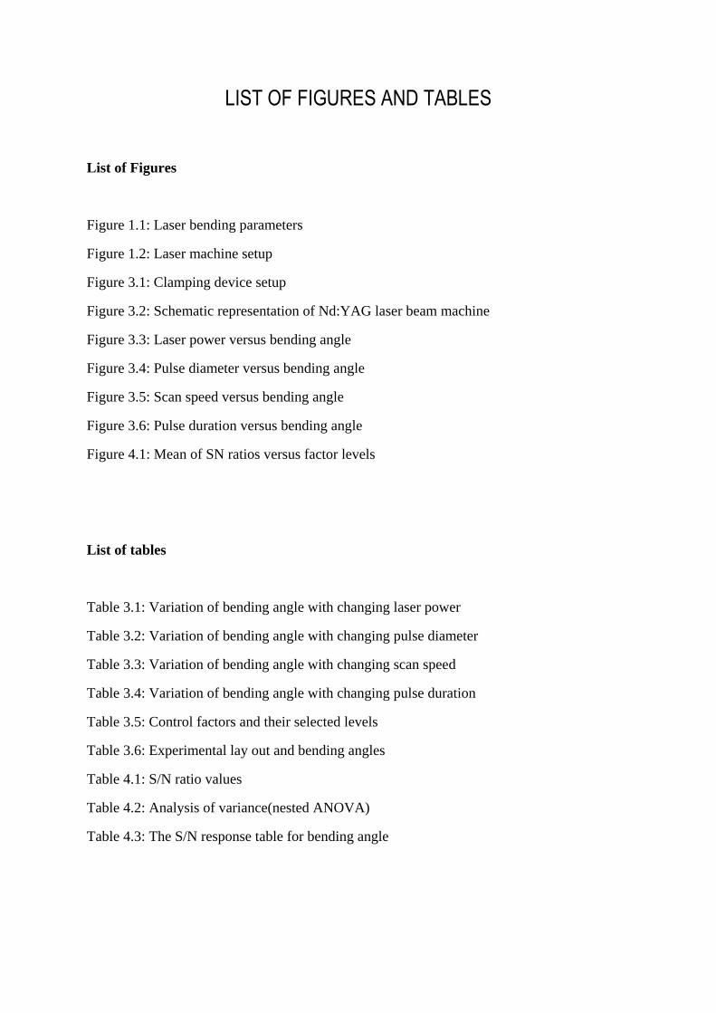
LIST OF FIGURES AND TABLES
List of Figures
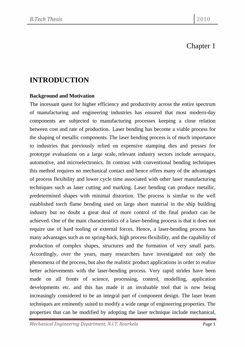
Figure 1.1: Laser bending parameters
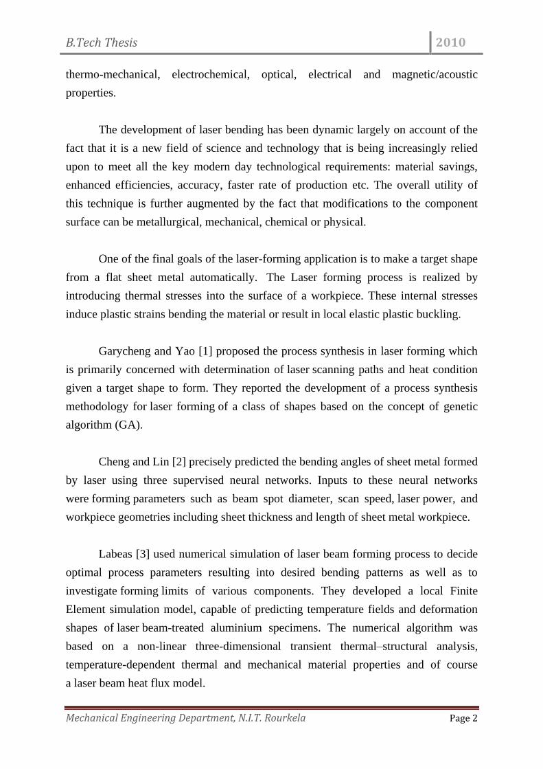
Figure 1.2: Laser machine setup
Figure 3.1: Clamping device setup
Figure 3.2: Schematic representation of Nd:YAG laser beam machine
Figure 3.3: Laser power versus bending angle
Figure 3.4: Pulse diameter versus bending angle
Figure 3.5: Scan speed versus bending angle
Figure 3.6: Pulse duration versus bending angle
Figure 4.1: Mean of SN ratios versus factor levels
List of tables
Table 3.1: Variation of bending angle with changing laser power
Table 3.2: Variation of bending angle with changing pulse diameter
Table 3.3: Variation of bending angle with changing scan speed
Table 3.4: Variation of bending angle with changing pulse duration
Table 3.5: Control factors and their selected levels
Table 3.6: Experimental lay out and bending angles
Table 4.1: S/N ratio values
Table 4.2: Analysis of variance(nested ANOVA)
Table 4.3: The S/N response table for bending angle
B.Tech Thesis 2010
Mechanical Engineering Department, N.I.T. Rourkela Page 1
Chapter 1
INTRODUCTION
Background and Motivation
The incessant quest for higher efficiency and productivity across the entire spectrum
of manufacturing and engineering industries has ensured that most modern-day
components are subjected to manufacturing processes keeping a close relation
between cost and rate of production. Laser bending has become a viable process for
the shaping of metallic components. The laser bending process is of much importance
to industries that previously relied on expensive stamping dies and presses for
prototype evaluations on a large scale, relevant industry sectors include aerospace,
automotive, and microelectronics. In contrast with conventional bending techniques
this method requires no mechanical contact and hence offers many of the advantages
of process flexibility and lower cycle time associated with other laser manufacturing
techniques such as laser cutting and marking. Laser bending can produce metallic,
predetermined shapes with minimal distortion. The process is similar to the well
established torch flame bending used on large sheet material in the ship building
industry but no doubt a great deal of more control of the final product can be
achieved. One of the main characteristics of a laser-bending process is that it does not
require use of hard tooling or external forces. Hence, a laser-bending process has
many advantages such as no spring-back, high process flexibility, and the capability of
production of complex shapes, structures and the formation of very small parts.
Accordingly, over the years, many researchers have investigated not only the
phenomena of the process, but also the realistic product applications in order to realize
better achievements with the laser-bending process. Very rapid strides have been
made on all fronts of science, processing, control, modelling, application
developments etc. and this has made it an invaluable tool that is now being
increasingly considered to be an integral part of component design. The laser beam
techniques are eminently suited to modify a wide range of engineering properties. The
properties that can be modified by adopting the laser technique include mechanical,
B.Tech Thesis 2010
Mechanical Engineering Department, N.I.T. Rourkela Page 2
thermo-mechanical, electrochemical, optical, electrical and magnetic/acoustic
properties.
The development of laser bending has been dynamic largely on account of the
fact that it is a new field of science and technology that is being increasingly relied
upon to meet all the key modern day technological requirements: material savings,
enhanced efficiencies, accuracy, faster rate of production etc. The overall utility of
this technique is further augmented by the fact that modifications to the component
surface can be metallurgical, mechanical, chemical or physical.
One of the final goals of the laser-forming application is to make a target shape
from a flat sheet metal automatically. The Laser forming process is realized by
introducing thermal stresses into the surface of a workpiece. These internal stresses
induce plastic strains bending the material or result in local elastic plastic buckling.
Garycheng and Yao [1] proposed the process synthesis in laser forming which
is primarily concerned with determination of laser scanning paths and heat condition
given a target shape to form. They reported the development of a process synthesis
methodology for laser forming of a class of shapes based on the concept of genetic
algorithm (GA).
Cheng and Lin [2] precisely predicted the bending angles of sheet metal formed
by laser using three supervised neural networks. Inputs to these neural networks
were forming parameters such as beam spot diameter, scan speed, laser power, and
workpiece geometries including sheet thickness and length of sheet metal workpiece.
Labeas [3] used numerical simulation of laser beam forming process to decide
optimal process parameters resulting into desired bending patterns as well as to
investigate forming limits of various components. They developed a local Finite
Element simulation model, capable of predicting temperature fields and deformation
shapes of laser beam-treated aluminium specimens. The numerical algorithm was
based on a non-linear three-dimensional transient thermal–structural analysis,
temperature-dependent thermal and mechanical material properties and of course
a laser beam heat flux model.
B.Tech Thesis 2010
Mechanical Engineering Department, N.I.T. Rourkela Page 3
Dubey and Yadava [4] used a hybrid approach of Taguchi method (TM) and
principal component analysis (PCA) for multi-objective optimization (MOO) of
pulsed Nd:YAG laser beam cutting (LBC) of nickel-based superalloy (SUPERNI 718)
sheet to achieve better cut qualities within existing resources.
Marya and Edwards [5] derived a simple dimensionless equation to find
process parameters in order to maximize bending angle and therefore assist in
the optimization of the process conditions.
Against this background, the present study has been undertaken to optimize the
process parameters involved in laser bending.Optimization technique is used to set the
values of input parameters like laser power, scan velocity, spot diameter and pulse
duration which are the controllable variables so as to get an optimum value of output.
Fig 1.1: Laser bending parameters
B.Tech Thesis 2010
Mechanical Engineering Department, N.I.T. Rourkela Page 4
Fig 1.2: Laser machine setup
B.Tech Thesis 2010
Mechanical Engineering Department, N.I.T. Rourkela Page 5
Chapter 2
LITERATURE REVIEW
This section provides an insight to the current technology available in the field of laser
forming. It also highlights various methods used by researchers on this topic.
Laser forming is a complex transient process that involves thermodynamics,
elastic-plastic mechanics, metallography etc. To control the deformation of metal
sheet, research of mechanics plays the major role. Forming mechanisms are governed
by the temperature field which in turn is influenced by geometry of workpiece, laser
power, laser spot diameter, laser pulse duration, scanning velocity, scanning path and
so on.
Here we get the feel of the topic by getting to know about various mechanisms
governing laser forming, influence of various parameters on the laser forming
operation.
Shichun and Jinsong [6] did the experimental study to find out the changes in
the bending angle with process parameters. Process parameters consist of laser energy
parameters, material parameters and sheet geometry parameters. The laser energy
parameters include laser power, path feed-rate, beam spot diameter and feed
number. Material parameters include coefficient of thermal expansion, density and
specific heat at constant pressure. Sheet geometry parameters include sheet length,
width and thickness. The experiments were performed on a type of LCM-
408 laser machine, with a CO2 laser source of 2 kW. Steel 08 (corresponding to AISI
1008), aluminium L3M (corresponding to ASTM 1050, annealed) and duralumin
LY12CZ (corresponding to ASTM 2024, quenched and naturally aged) sheets were
chosen as the working materials for the tests of laser bending. The sheet surfaces were
coated with carbon black before testing in order to increase the absorption of laser
power. The sheet metals after irradiation were cooled naturally. The conclusions
B.Tech Thesis 2010
Mechanical Engineering Department, N.I.T. Rourkela Page 6
drawn from the tests were that the bending angle varied in direct proportion to
the laser power and feed number, and in inverse proportion to the path feed-rate and
beam spot diameter. The material parameters are related by a thermal-effect index,
which can be related as R=αth/ρcp, where αth is the coefficient of thermal expansion, ρ
is the density of the material and cp is the specific heat capacity at constant pressure.
The bending angle was found to be increasing with increase in the index R. There was
no significant influence of the strength at room temperature on the bending angle.
Among the sheet geometric parameters only sheet thickness had remarkable effect on
the bending angle, which decreases sharply with increase in the sheet thickness.
Shen and Yao [7] did the experimental study of mechanical properties of sheet
metal after laser irradiation. Many sheet metal components formed by mechanical
pressing are subjected to cyclic loading during their service life. The investigations
indicated that the fatigue performance of the pressed components decreased
significantly compared to the stock plate specimens of the same material . This
decrease in life is attributed not only to the increase in tensile residual stress but more
importantly also to the degradation of the material gains resulting from the mechanical
forming process. The observed decrease in fatigue life has led to a search for an
alternative manufacturing process for enhancing the fatigue
performance. Laser forming is a flexible manufacturing process that forms a metal
sheet by means of thermal stresses induced by external heat instead of external force.
Some analytical models for bending angle induced by the straight line scan
in laser bending have been presented, and numerical simulations have also been
performed using various commercial codes for laser bending. In order to increase the
plastic deformation, the method that of adding external forces or bending moments
during the laser forming process has been applied . For a multi-scans study, numerical
investigations have been carried out to examine the difference in temperature fields
and plastic deformations between the two simultaneous laser scans and the sequential
scans . The effects of scan intervals on the bending angle for two-scan laser forming
along the same path were investigated using numerical simulation .
B.Tech Thesis 2010
Mechanical Engineering Department, N.I.T. Rourkela Page 7
However, this study focused on the design of the fatigue life test, and the
influence of the laser processing parameters on the fatigue life was of little concern.
The objectives of this study are to characterize the mechanical properties of laser-
formed samples. The tensile properties and the low-cycle fatigue life under
different laser processing parameters were investigated. A fractographic examination
was also made to understand the microscopic behaviours of the fatigue crack initiation
and propagation.
Monotonic tensile behaviour of low carbon steel specimens with
different laser processing parameters was investigated. The tensile properties of
specimens after laser forming changed slightly compared to the unprocessed ones.
Low-cycle fatigue damage and life of the specimens were compared with that of the
unscanned ones. The enhancement in fatigue life as indicated by the laser-formed
specimens was encouraging. SEM analysis also revealed the reason why laser-formed
low carbon steel has a longer fatigue life than before laser forming. The compressive
residual strain is the most important reason why the fatigue life of low carbon steel
after laser forming improves.
Garycheng and Yao [1] developed a process synthesis methodology by genetic
algorithm. GAs, which are optimization techniques based on probabilistic transition
rules, have been successfully implemented for a wide range of problems in physical
and social sciences, engineering and operations research, and computer sciences . GAs
mimic the natural evolution process by which superior creatures evolve while inferior
ones fade out from the population as generations go on. GAs have been proved to be a
robust, simple-to-implement method, which can handle a large set of parameters. The
disadvantages of GAs include their long computational time, and the semi-empirical
nature of the algorithm parameter selection procedure. Here GA based approach was
presented for process synthesis applicable to laser forming of a class of shapes. The
synthesis scheme developed in this study has the advantage of being able to handling a
large number of decision variables. This approach was validated through several
cases. The effects of fitness function and control parameters of GAs (population size,
crossover rate and mutation rate) on the convergence of the design process were also
B.Tech Thesis 2010
Mechanical Engineering Department, N.I.T. Rourkela Page 8
investigated. It was demonstrated through this investigation that given a desired shape
for the class of shapes concerned, the approach used was effective in determining the
optimal values of diverse process parameters for laser forming process. It was also
shown that it is able to handle a large number of decision variables. When the number
of decision variables was close to 30, however, it took a large number of generations
to achieve convergence. Investigations showed that the algorithm control parameters
and the fitness function type have significant effects on the GA synthesis results. It
was shown that a proper form of fitness function is important to balance among
competing objectives, such as geometric accuracy, forming time, and energy
consumption.
Kim and Na [8] developed a method for 3D laser forming of sheet metal by
using a geometrical information rather than a complicated stress-strain analysis.
Forming sheet metal by laser-induced thermal stress (laser forming) is considered to
offer great potential for rapid prototyping and other flexible manufacturing. In order to
apply the laser forming process to real 3D products, a method that encompasses the
whole process planning, including the laser irradiation patterns, laser power, and
travel speed, when the target shape is given. In this work a method for 3D laser
forming of sheet metal is proposed by using a geometrical information rather than a
complicated stress-strain analysis. Using this method the total calculation time is
reduced considerably while affording strong potential for enhanced accuracy.
Hsieh and Lin [9] investigated numerically and experimentally the buckling
mechanism of a thin metal tube during laser forming in this study. Metal tubes made
of 304 stainless steel were heated by a CO2 Gaussian laser beam, which induced the
buckling phenomenon on the tube surface due to elastic–plastic deformation. This
uncoupled thermal–mechanical problem was solved using a three-dimensional finite
element method and was subsequently satisfactorily verified with displacement
measurements. The transient bending angle and residual stress of the thin metal tube
under specific operation conditions were also studied.
B.Tech Thesis 2010
Mechanical Engineering Department, N.I.T. Rourkela Page 9
Guan et al. [10] established a three-dimensional coupled thermo-mechanical
finite element model. The laser-forming process is a new flexible forming process
without rigid tools and external force. The sheet metal is formed by internal localized
thermal stress induced by laser. Material properties play an important role in laser
forming. A three-dimensional coupled thermo-mechanical finite element model is
established in this paper. The laser-bending process of a sheet blank is simulated
numerically using the model. The relationship between the bending angle and material
property parameters, such as Young’s modulus, yield strength, coefficient of thermal
expansion, specific heat, and thermal conductivity, are studied extensively by FEM
simulation. The simulations show that the material with lower Young’s modulus and
yield strength can produce a larger bending angle. The thermal expansion coefficient
is nearly in direct proportion to the bending angle. The bending angle decreases with
the increase of the heat conductivity.
Magee et al. [11] developed a non-contact laser forming (LF) demonstrator
system to demonstrate the process on a large primitive shape. A fundamental study
was carried out which examined the elects of laser-forming parameters on tokens of
an aluminium and a titanium alloy. Energy, geometrical and metallurgical influences
were investigated and are summarized here. Results of the study showed that LF of
these aerospace materials is possible using a large operating envelope of laser-
processing parameters. A range of metallurgical elects resulted on the titanium alloy
and these are traced here. Depending on how the energy input was supplied to the
plate surface, various geometrical elects resulted. These elects are discussed. Using
the knowledge gathered from the fundamental study, a prototype LF system was built.
The components of the system and the forming of a primitive shape on it are
discussed. Conclusions from the study indicate that the future work lies in the
development of the demonstrator for primitive 3-D shapes and the integration of a
knowledge-based system.
Shen et al. [12] proposed a new mechanism of laser forming. Laser forming is
a complex thermal–mechanical process. To reveal the mechanisms dominating the
B.Tech Thesis 2010
Mechanical Engineering Department, N.I.T. Rourkela Page 10
forming process is essential to control accurately the deformation of metal plate.
Numerous efforts had been made to understand the mechanisms of laser forming.
Proposed mechanisms mainly included temperature gradient mechanism, buckling
mechanism and upsetting mechanism. However, in the investigation of laser forming,
it is found that the above three mechanisms cannot explain fully the process of
deformation. Based on the study of thermal transfer and elastic–plastic deformation,
the above three mechanisms are further explained. In addition, a new mechanism,
coupling mechanism, is proposed. To verify the validity of the mechanisms proposed,
numerical simulations are carried out, and simulation results are consistent with
analyses of mechanisms.
Ueda et al. [13] used temperature distribution for determining the bending
angle. Laser forming is a thermal process for the deformation of sheet metal by
inducing localized thermal stress. Temperature distribution is the most important
factor for determining the bending angle of the sheet metal. In the present study, the
combined effect of the temperature of the workpiece, the temperature gradient
between the two surfaces of the sheet, the size of the area irradiated with laser beam,
and the thickness of the workpiece is investigated both theoretically and
experimentally. The temperature at the surface irradiated with CO2 laser and at the
opposite surface are simultaneously measured using two-color pyrometers with an
optical fiber. The bending angle has been found to increase with the spot diameter and
workpiece surface temperature and decrease with workpiece thickness.
Thomson and Pridham [14] discussed the development of a basic process
monitoring and control system. Laser forming is a process that uses the energy of
relatively high powered lasers to cause permanent deformation to components by
inducing localized thermal stresses. This paper briefly discusses laser forming and the
development of a basic process monitoring and control system used to overcome
various problems due to the complex nature of the lasers and the manner in which
they interact with material.
B.Tech Thesis 2010
Mechanical Engineering Department, N.I.T. Rourkela Page 11
Chapter 3
MATERIALS AND METHODS
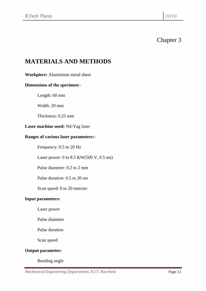
Workpiece: Aluminium metal sheet
Dimensions of the specimen:-
Length: 60 mm
Width: 20 mm
Thickness: 0.25 mm
Laser machine used: Nd-Yag laser
Ranges of various laser parameters:-
Frequency: 0.5 to 20 Hz
Laser power: 0 to 8.5 KW(500 V, 0.5 ms)
Pulse diameter: 0.2 to 2 mm
Pulse duration: 0.5 to 20 ms
Scan speed: 0 to 20 mm/sec
Input parameters:
Laser power
Pulse diameter
Pulse duration
Scan speed
Output parameter:
Bending angle
B.Tech Thesis 2010
Mechanical Engineering Department, N.I.T. Rourkela Page 12
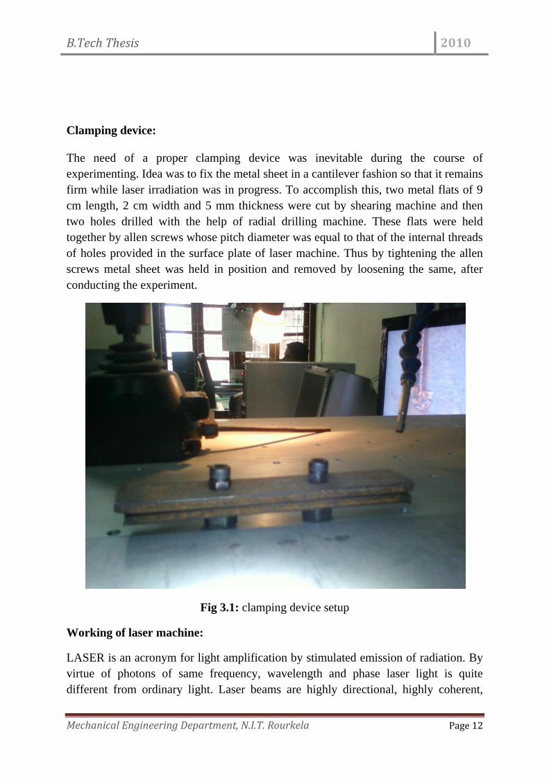
Clamping device:
The need of a proper clamping device was inevitable during the course of
experimenting. Idea was to fix the metal sheet in a cantilever fashion so that it remains
firm while laser irradiation was in progress. To accomplish this, two metal flats of 9
cm length, 2 cm width and 5 mm thickness were cut by shearing machine and then
two holes drilled with the help of radial drilling machine. These flats were held
together by allen screws whose pitch diameter was equal to that of the internal threads
of holes provided in the surface plate of laser machine. Thus by tightening the allen
screws metal sheet was held in position and removed by loosening the same, after
conducting the experiment.
Fig 3.1: clamping device setup
Working of laser machine:
LASER is an acronym for light amplification by stimulated emission of radiation. By
virtue of photons of same frequency, wavelength and phase laser light is quite
different from ordinary light. Laser beams are highly directional, highly coherent,
B.Tech Thesis 2010
Mechanical Engineering Department, N.I.T. Rourkela Page 13
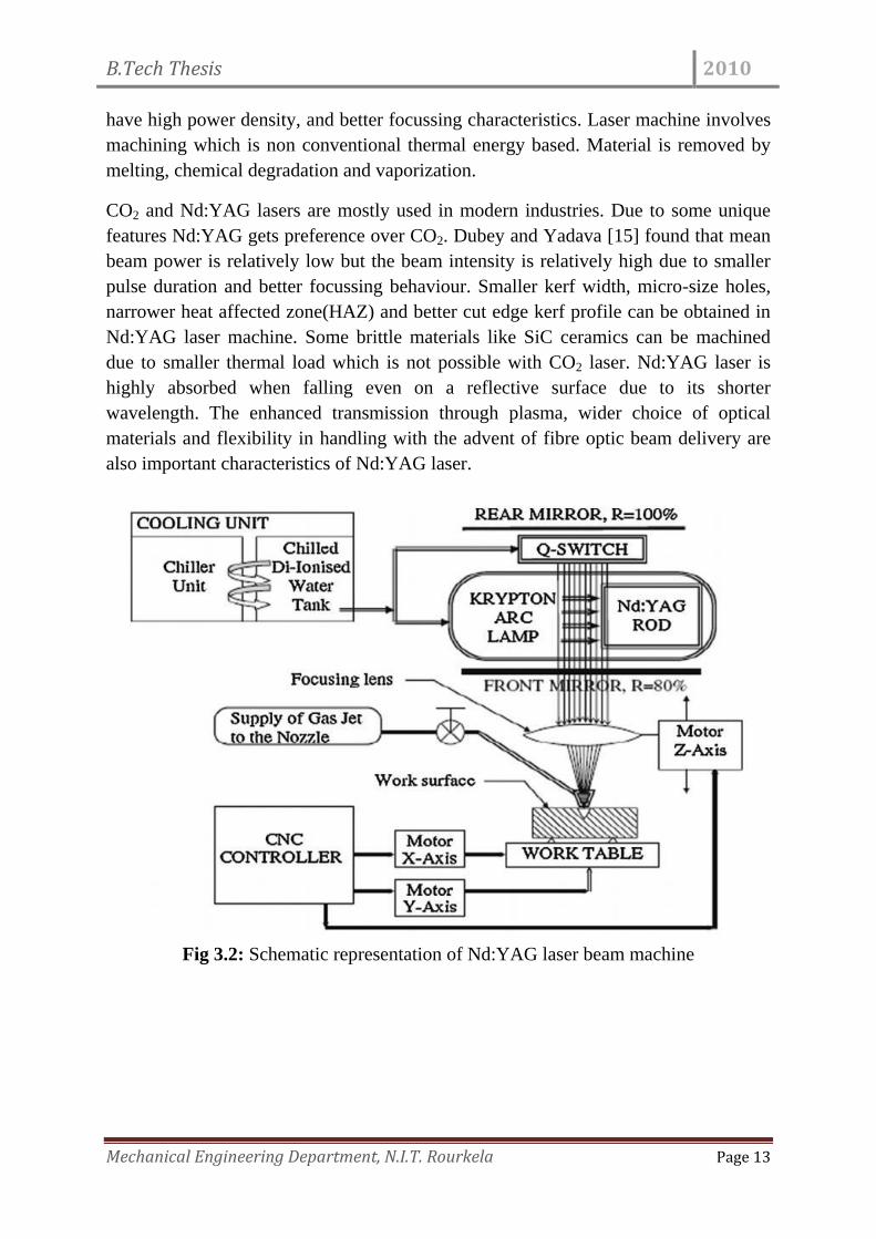
have high power density, and better focussing characteristics. Laser machine involves
machining which is non conventional thermal energy based. Material is removed by
melting, chemical degradation and vaporization.
CO2 and Nd:YAG lasers are mostly used in modern industries. Due to some unique
features Nd:YAG gets preference over CO2. Dubey and Yadava [15] found that mean
beam power is relatively low but the beam intensity is relatively high due to smaller
pulse duration and better focussing behaviour. Smaller kerf width, micro-size holes,
narrower heat affected zone(HAZ) and better cut edge kerf profile can be obtained in
Nd:YAG laser machine. Some brittle materials like SiC ceramics can be machined
due to smaller thermal load which is not possible with CO2 laser. Nd:YAG laser is
highly absorbed when falling even on a reflective surface due to its shorter
wavelength. The enhanced transmission through plasma, wider choice of optical
materials and flexibility in handling with the advent of fibre optic beam delivery are
also important characteristics of Nd:YAG laser.
Fig 3.2: Schematic representation of Nd:YAG laser beam machine
B.Tech Thesis 2010
Mechanical Engineering Department, N.I.T. Rourkela Page 14
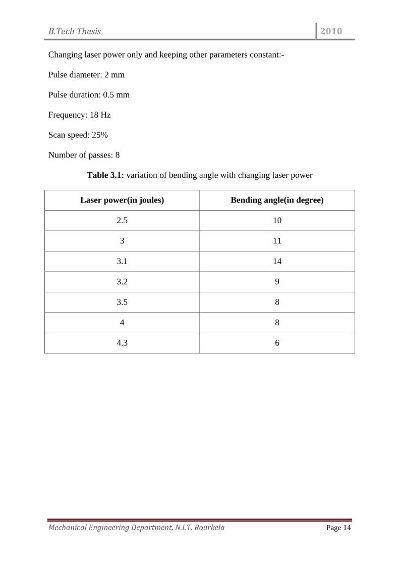
Changing laser power only and keeping other parameters constant:-
Pulse diameter: 2 mm
Pulse duration: 0.5 mm
Frequency: 18 Hz
Scan speed: 25%
Number of passes: 8
Table 3.1: variation of bending angle with changing laser power
Laser power(in joules) Bending angle(in degree)
2.5 10
3 11
3.1 14
3.2 9
3.5 8
4 8
4.3 6
B.Tech Thesis 2010
Mechanical Engineering Department, N.I.T. Rourkela Page 15
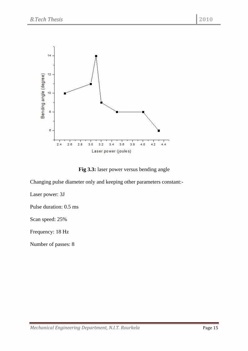
Fig 3.3: laser power versus bending angle
Changing pulse diameter only and keeping other parameters constant:-
Laser power: 3J
Pulse duration: 0.5 ms
Scan speed: 25%
Frequency: 18 Hz
Number of passes: 8
B.Tech Thesis 2010
Mechanical Engineering Department, N.I.T. Rourkela Page 16
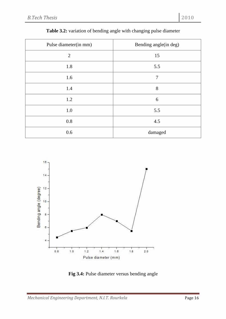
Table 3.2: variation of bending angle with changing pulse diameter
Pulse diameter(in mm) Bending angle(in deg)
2 15
1.8 5.5
1.6 7
1.4 8
1.2 6
1.0 5.5
0.8 4.5
0.6 damaged
Fig 3.4: Pulse diameter versus bending angle
B.Tech Thesis 2010
Mechanical Engineering Department, N.I.T. Rourkela Page 17
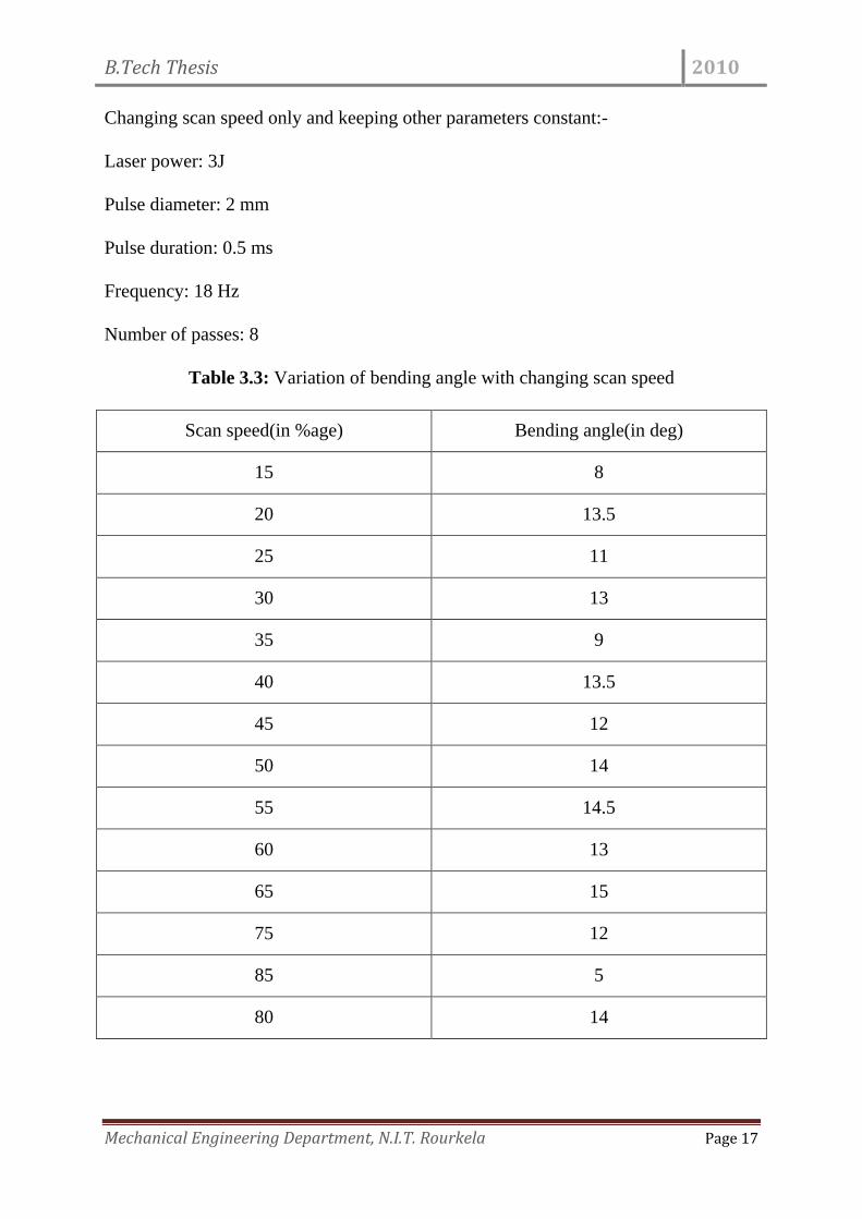
Changing scan speed only and keeping other parameters constant:-
Laser power: 3J
Pulse diameter: 2 mm
Pulse duration: 0.5 ms
Frequency: 18 Hz
Number of passes: 8
Table 3.3: Variation of bending angle with changing scan speed
Scan speed(in %age) Bending angle(in deg)
15 8
20 13.5
25 11
30 13
35 9
40 13.5
45 12
50 14
55 14.5
60 13
65 15
75 12
85 5
80 14
B.Tech Thesis 2010
Mechanical Engineering Department, N.I.T. Rourkela Page 18
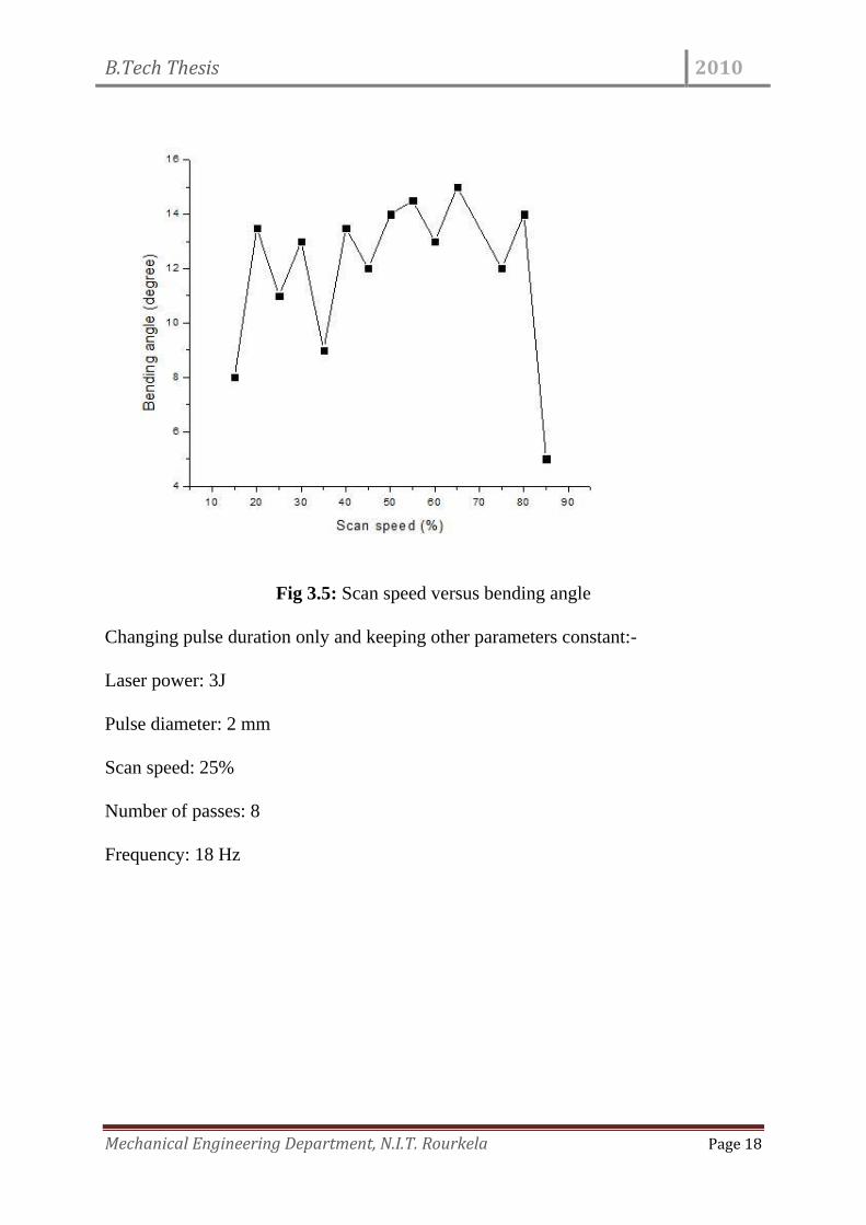
Fig 3.5: Scan speed versus bending angle
Changing pulse duration only and keeping other parameters constant:-
Laser power: 3J
Pulse diameter: 2 mm
Scan speed: 25%
Number of passes: 8
Frequency: 18 Hz
B.Tech Thesis 2010
Mechanical Engineering Department, N.I.T. Rourkela Page 19
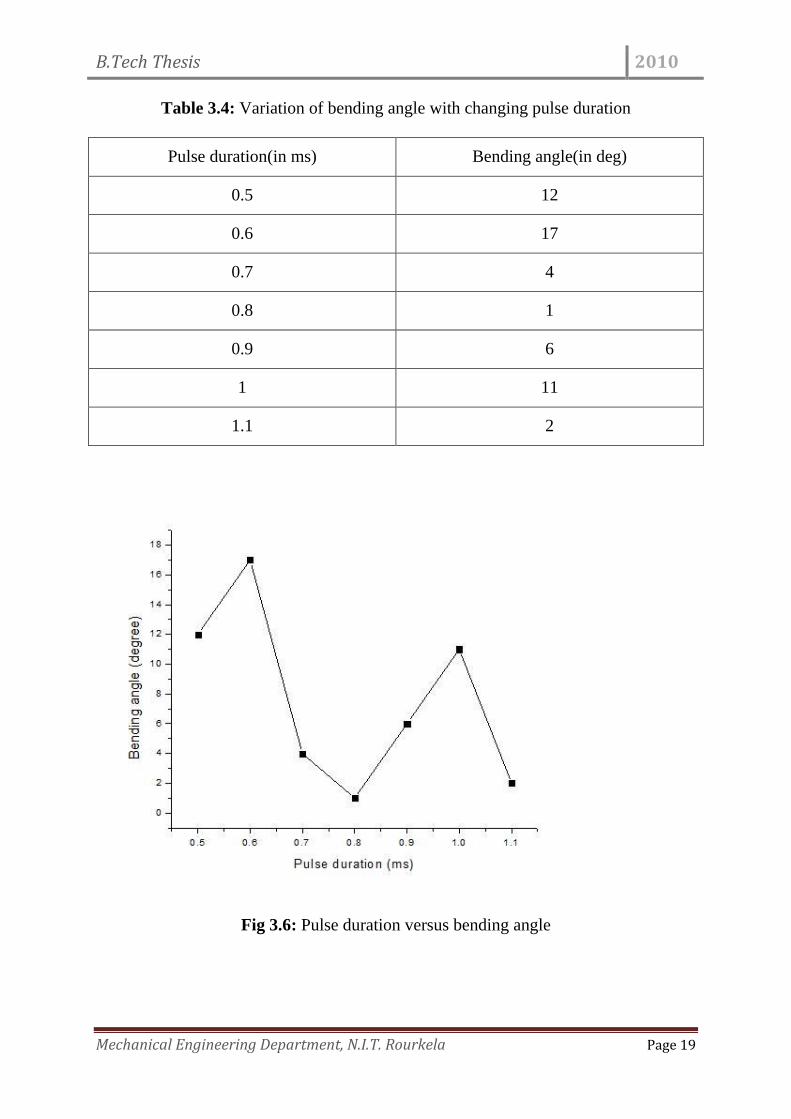
Table 3.4: Variation of bending angle with changing pulse duration
Pulse duration(in ms) Bending angle(in deg)
0.5 12
0.6 17
0.7 4
0.8 1
0.9 6
1 11
1.1 2
Fig 3.6: Pulse duration versus bending angle
B.Tech Thesis 2010
Mechanical Engineering Department, N.I.T. Rourkela Page 20
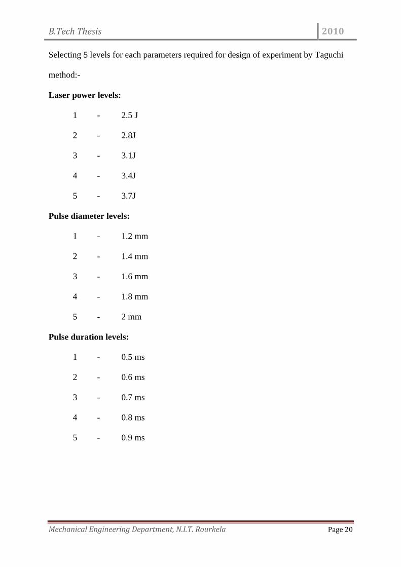
Selecting 5 levels for each parameters required for design of experiment by Taguchi
method:-
Laser power levels:
1 - 2.5 J
2 - 2.8J
3 - 3.1J
4 - 3.4J
5 - 3.7J
Pulse diameter levels:
1 - 1.2 mm
2 - 1.4 mm
3 - 1.6 mm
4 - 1.8 mm
5 - 2 mm
Pulse duration levels:
1 - 0.5 ms
2 - 0.6 ms
3 - 0.7 ms
4 - 0.8 ms
5 - 0.9 ms
B.Tech Thesis 2010
Mechanical Engineering Department, N.I.T. Rourkela Page 21
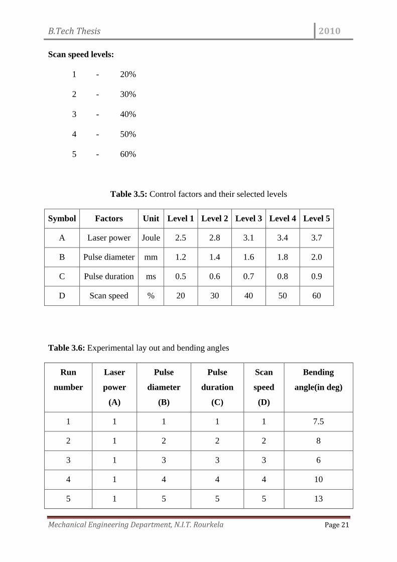
Scan speed levels:
1 - 20%
2 - 30%
3 - 40%
4 - 50%
5 - 60%
Table 3.5: Control factors and their selected levels
Symbol Factors Unit Level 1 Level 2 Level 3 Level 4 Level 5
A Laser power Joule 2.5 2.8 3.1 3.4 3.7
B Pulse diameter mm 1.2 1.4 1.6 1.8 2.0
C Pulse duration ms 0.5 0.6 0.7 0.8 0.9
D Scan speed % 20 30 40 50 60
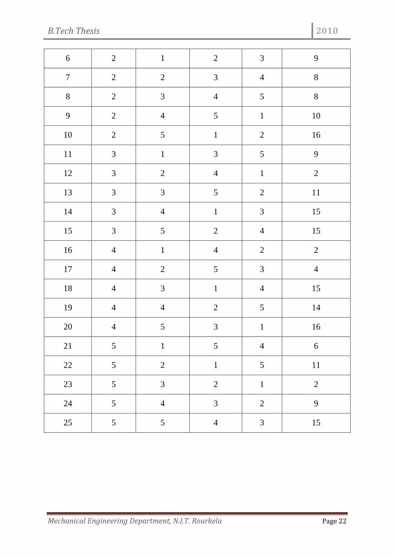
Table 3.6: Experimental lay out and bending angles
Run
number
Laser
power
(A)
Pulse
diameter
(B)
Pulse
duration
(C)
Scan
speed
(D)
Bending
angle(in deg)
1 1 1 1 1 7.5
2 1 2 2 2 8
3 1 3 3 3 6
4 1 4 4 4 10
5 1 5 5 5 13
B.Tech Thesis 2010
Mechanical Engineering Department, N.I.T. Rourkela Page 22
6 2 1 2 3 9
7 2 2 3 4 8
8 2 3 4 5 8
9 2 4 5 1 10
10 2 5 1 2 16
11 3 1 3 5 9
12 3 2 4 1 2
13 3 3 5 2 11
14 3 4 1 3 15
15 3 5 2 4 15
16 4 1 4 2 2
17 4 2 5 3 4
18 4 3 1 4 15
19 4 4 2 5 14
20 4 5 3 1 16
21 5 1 5 4 6
22 5 2 1 5 11
23 5 3 2 1 2
24 5 4 3 2 9
25 5 5 4 3 15
B.Tech Thesis 2010
Mechanical Engineering Department, N.I.T. Rourkela Page 23
Chapter 4
RESULTS AND DISCUSSIONS
Laser bending involves a number of process variables, which contribute in a large way
to the quality of bending achieved. During bending operation, various operating
parameters are determined mostly based on past experience. It therefore does not
provide the optimal set of parameters for a particular objective. In order to obtain the
best result with regard to any specific bending characteristic, accurate identification of
significant control parameters is essential. This chapter is devoted to analyze the
experimentally obtained results on laser bending made at different operational
conditions. For this purpose, a statistical technique called Taguchi experimental
design method is used. Factors are identified according to their influence on the laser
bending.
TAGUCHI EXPERIMENTAL DESIGN
Taguchi method of experimental design is a simple, efficient and systematic approach
to optimize designs for performance and cost . In the present work, this method is
applied to the process of laser bending for identifying the significant process variables
influencing laser bending. The levels of these factors are also found out so that the
process variables can be optimized within the test range.
Experimental Design
B.Tech Thesis 2010
Mechanical Engineering Department, N.I.T. Rourkela Page 24
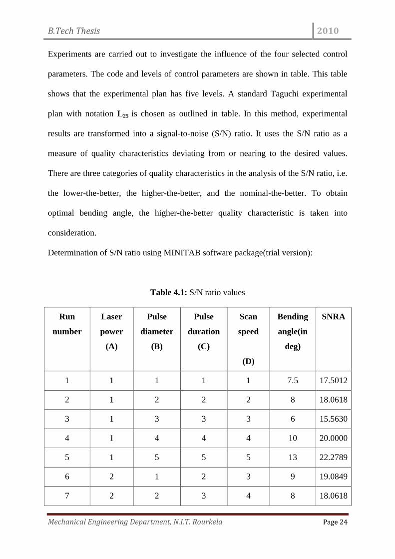
Experiments are carried out to investigate the influence of the four selected control
parameters. The code and levels of control parameters are shown in table. This table
shows that the experimental plan has five levels. A standard Taguchi experimental
plan with notation L25 is chosen as outlined in table. In this method, experimental
results are transformed into a signal-to-noise (S/N) ratio. It uses the S/N ratio as a
measure of quality characteristics deviating from or nearing to the desired values.
There are three categories of quality characteristics in the analysis of the S/N ratio, i.e.
the lower-the-better, the higher-the-better, and the nominal-the-better. To obtain
optimal bending angle, the higher-the-better quality characteristic is taken into
consideration.
Determination of S/N ratio using MINITAB software package(trial version):
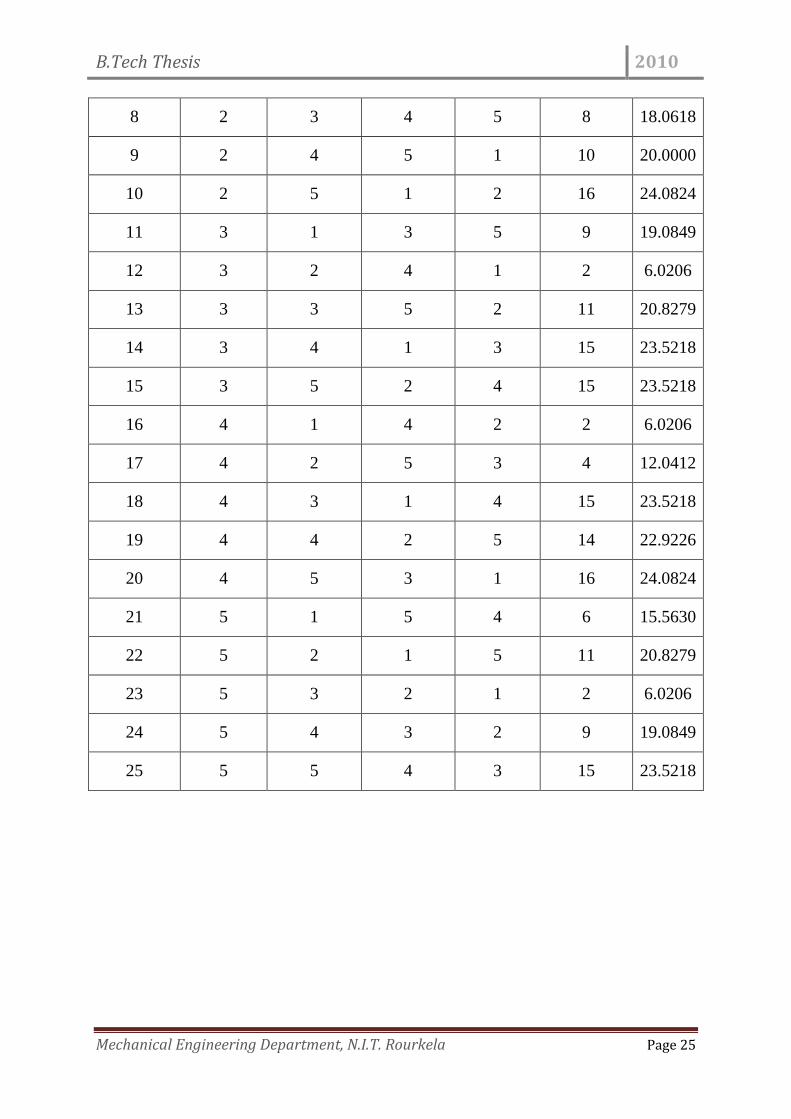
Table 4.1: S/N ratio values
Run
number
Laser
power
(A)
Pulse
diameter
(B)
Pulse
duration
(C)
Scan
speed
(D)
Bending
angle(in
deg)
SNRA
1 1 1 1 1 7.5 17.5012
2 1 2 2 2 8 18.0618
3 1 3 3 3 6 15.5630
4 1 4 4 4 10 20.0000
5 1 5 5 5 13 22.2789
6 2 1 2 3 9 19.0849
7 2 2 3 4 8 18.0618
B.Tech Thesis 2010
Mechanical Engineering Department, N.I.T. Rourkela Page 25
8 2 3 4 5 8 18.0618
9 2 4 5 1 10 20.0000
10 2 5 1 2 16 24.0824
11 3 1 3 5 9 19.0849
12 3 2 4 1 2 6.0206
13 3 3 5 2 11 20.8279
14 3 4 1 3 15 23.5218
15 3 5 2 4 15 23.5218
16 4 1 4 2 2 6.0206
17 4 2 5 3 4 12.0412
18 4 3 1 4 15 23.5218
19 4 4 2 5 14 22.9226
20 4 5 3 1 16 24.0824
21 5 1 5 4 6 15.5630
22 5 2 1 5 11 20.8279
23 5 3 2 1 2 6.0206
24 5 4 3 2 9 19.0849
25 5 5 4 3 15 23.5218
B.Tech Thesis 2010
Mechanical Engineering Department, N.I.T. Rourkela Page 26
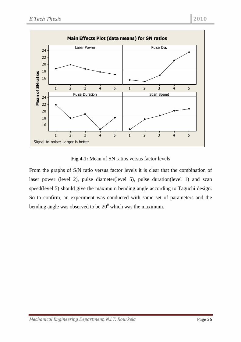
Fig 4.1: Mean of SN ratios versus factor levels
From the graphs of S/N ratio versus factor levels it is clear that the combination of
laser power (level 2), pulse diameter(level 5), pulse duration(level 1) and scan
speed(level 5) should give the maximum bending angle according to Taguchi design.
So to confirm, an experiment was conducted with same set of parameters and the
bending angle was observed to be 200 which was the maximum.
Me
an
of
SN
ra
tio
s
54321
24
22
20
18
16
54321
54321
24
22
20
18
16
54321
Laser Power Pulse Dia.
Pulse Duration Scan Speed
Main Effects Plot (data means) for SN ratios
Signal-to-noise: Larger is better
B.Tech Thesis 2010
Mechanical Engineering Department, N.I.T. Rourkela Page 27
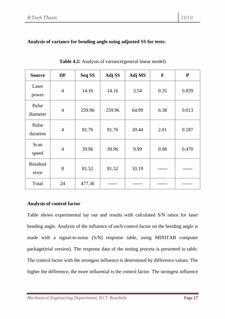
Analysis of variance for bending angle using adjusted SS for tests:
Table 4.2: Analysis of variance(general linear model)
Source DF Seq SS Adj SS Adj MS F P
Laser
power 4 14.16 14.16 3.54 0.35 0.839
Pulse
diameter 4 259.96 259.96 64.99 6.38 0.013
Pulse
duration 4 81.76 81.76 20.44 2.01 0.187
Scan
speed 4 39.96 39.96 9.99 0.98 0.470
Residual
error 8 81.52 81.52 10.19 ------ ------
Total 24 477.36 ------ ------ ------ ------
Analysis of control factor
Table shows experimental lay out and results with calculated S/N ratios for laser
bending angle. Analysis of the influence of each control factor on the bending angle is
made with a signal-to-noise (S/N) response table, using MINITAB computer
package(trial version). The response data of the testing process is presented in table.
The control factor with the strongest influence is determined by difference values. The
higher the difference, the more influential is the control factor. The strongest influence
B.Tech Thesis 2010
Mechanical Engineering Department, N.I.T. Rourkela Page 28
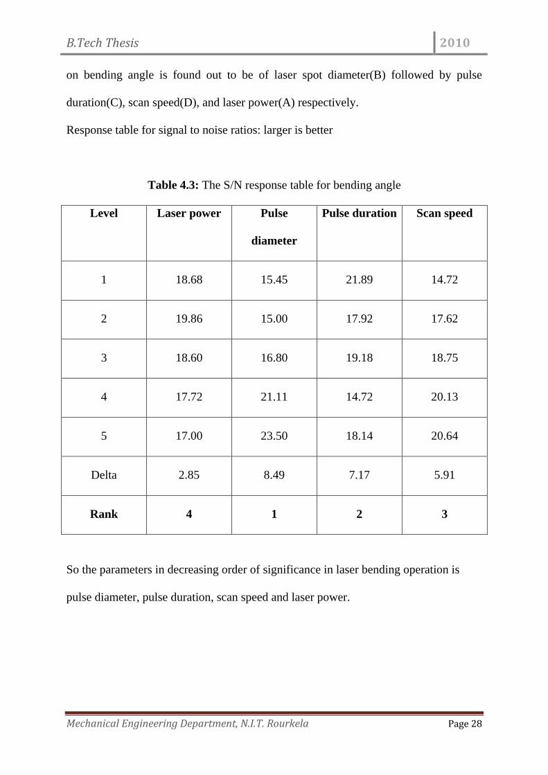
on bending angle is found out to be of laser spot diameter(B) followed by pulse
duration(C), scan speed(D), and laser power(A) respectively.
Response table for signal to noise ratios: larger is better
Table 4.3: The S/N response table for bending angle
Level Laser power Pulse
diameter
Pulse duration Scan speed
1 18.68 15.45 21.89 14.72
2 19.86 15.00 17.92 17.62
3 18.60 16.80 19.18 18.75
4 17.72 21.11 14.72 20.13
5 17.00 23.50 18.14 20.64
Delta 2.85 8.49 7.17 5.91
Rank 4 1 2 3
So the parameters in decreasing order of significance in laser bending operation is
pulse diameter, pulse duration, scan speed and laser power.
B.Tech Thesis 2010
Mechanical Engineering Department, N.I.T. Rourkela Page 29
Chapter 4
CONCLUSIONS & SCOPE FOR FUTURE WORK
Conclusions
This experimental investigation on the laser bending parameters have led to the
following specific conclusions:
1. Laser spot diameter is the most significant factor followed by laser pulse
duration, laser scanning speed and then laser power.
2. There is no specific pattern of variation of bending angle obtained by
changing only one parameter while keeping the others constant.
3. Maximum bending angle predicted by Taguchi analysis for a particular set
of parameters was found correct.
Scope for future work
This work leaves a wide scope for future investigators to explore many other aspects
of laser beam bending. Some recommendations for future research include:
Application of other optimization techniques and comparing results with
Taguchi method.
B.Tech Thesis 2010
Mechanical Engineering Department, N.I.T. Rourkela Page 30
R E F E R E N C E S 1. GaryCheng J. and Yao Y.L., Process synthesis of laser forming by genetic algorithm, International
Journal of Machine Tools and Manufacture, Volume 44, Issue 15, December 2004, pp 1619-1628.
2. Cheng P. J. and Lin S. C., Using neural networks to predict bending angle of sheet metal formed by
laser, International Journal of Machine Tools and Manufacture, Volume 40, Issue 8, June 2000, pp
1185-1197
3. Labeas G.N., Development of a local three-dimensional numerical simulation model for the laser
forming process of aluminium components, Journal of Materials Processing Technology, Volume 207,
Issues 1-3, 16 October 2008, pp 248-257.
4. Dubey A.K. and Yadava V., Multi-objective optimization of Nd:YAG laser cutting of nickel-based
superalloy sheet using orthogonal array with principal component analysis, Optics and Lasers in
Engineering, Volume 46, Issue 2, February 2008, pp 124-132.
5. Marya M. and Edwards G. R., An analytical model for the optimization of the laser bending of titanium
Ti–6Al–2Sn–4Zr–2Mo, Journal of Materials Processing Technology, Volume 124, Issue 3, 20 June 2002,
pp 337-344.
6. Shichun W. and Jinsong Z., An experimental study of laser bending for sheet metals, Journal of
Materials Processing Technology, Volume 110, Issue 2, 19 March 2001, pp 160-163.
7. Shen H. and Yao Z., study on mechanical properties after laser forming, Optics and Lasers in
Engineering, Volume 47, Issue 1, January 2009, pp 111-117.
8. Kim J. and Na S.J., 3D laser-forming strategies for sheet metal by geometrical information, Optics &
Laser Technology, Volume 41, Issue 6, September 2009, pp 843-852.
9. Hsieh H. and Lin J., Study of the buckling mechanism in laser tube forming, Optics & Laser Technology,
Volume 37, Issue 5, July 2005, pp 402-409.
10. Guan Y., Sun S., Zhao G. and Luan Y., Influence of material properties on the laser-forming process of
sheet metals, Journal of Materials Processing Technology, Volume 167, Issue 1, 25 August 2005, pp
124-131.
11. Magee J., Sidhu J. and Cooke R. L., A Prototype laser forming system, Optics and Lasers in
Engineering, Volume 34, Issues 4-6, October 2000, pp 339-353.
12. Shi Y., Yao Z., Shen H. and Hu J., Research on the mechanisms of laser forming for the metal plate,
International Journal of Machine Tools and Manufacture, Volume 46, Issues 12-13, October 2006, pp
1689-1697.
13. Ueda T., Sentoku E., Yamada K. and Hosokawa A., Temperature Measurement in Laser Forming of
Sheet Metal, CIRP Annals - Manufacturing Technology, Volume 54, Issue 1, 2005, pp 179-182.
14. Thomson G. and Pridham M., Improvements to laser forming through process control refinements,
Optics & Laser Technology, Volume 30, Issue 2, March 1998, pp 141-146.
B.Tech Thesis 2010
Mechanical Engineering Department, N.I.T. Rourkela Page 31
15. Dubey A. K. and Yadava V., experimental study of Nd-YAG laser beam machining-an overview, journal
of materials processing technology, 195 (2006) 15-26
16. Geiger M. and Vollertsen F., The mechanisms of laser forming, CIRP Annals 42 (1993), pp. 301–304.
17. Vollertsen F., An analytical model for laser bending, Laser in Engineering 2 (1994), pp. 261–276.
18. Vollertsen F., Geiger M. and Li W.M., FDM- and FEM-simulation of laser forming: a comparative study,
In:Advanced Technology of Plasticity, Proceedings of the Fourth International Conference on
Technology of Plasticity (1993), pp. 1793–1798.
19. Kermanidis Th.B., Kyrsanidi A.K. and Pantelakis S.G., Numerical simulation of the laser forming process
in metallic sheet metals, In: Proceedings of the International Conference on Computer Methods and
Experimental Measurements for Surface Treatment Effects (1997), pp. 307–316.
20. Grefenstette J.J. , Optimization of control parameters for genetic algorithms, IEEE Transactions on
Systems, Man and Cybernetics, vol. SMC-16, No. 1, 1986, pp. 122–128.
21. Montgomery, D.C. (1997). Design and Analysis of Experiments, 4th Edition. John Wiley & Sons, Inc.
22. Geiger M., Vollertsen F.and Deinzer G., Flexible straightening of car body shells by laser forming,
In: Sheet Metal and Stamping Symping Symposium SAE Special Publication, no. 944 SAE (1993), pp.
37–44.
23. Fisher, R.A. (1925). Statistical Methods for Research Workers. Oliver & Boyd,Edinburgh.
24. Hogg, R.V. and Ledolter, J. (1987). Applied Statistics for Engineers and Physical scientists. Macmillan
Publishing Company, NY.
25. Kao M.T., Elementary study of laser sheet formingof single curvature, Master Thesis of Department of
Power Mechanical Engineering, Tsing Hua University, 1996..
26. Vollertsen F. and Rodle M., Model for the temperature gradient mechanism
of laser bending. LaserAssisted Net Shape Engineering Proceedings of the LANE 1 (1994), pp. 371–378.
27. Cheng J. and Yao Y.L., Microstructure integrated modeling of multiscan laser forming. ASME
Transactions, Journal of Manufacturing Science and Engineering 124 2 (2002), pp. 379–388.
28. Li W. and Yao Y.L., Numerical and experimental study of strain rate effects in laser forming. ASME
Transactions, Journal of Manufacturing Science and Engineering 122 3 (2000), pp. 445–451.
29. Vollertsen F., Mechanism and models for laser forming. In: Proceedings of the Laser Assisted Net
Shape Engineering (LANE ’94) vol. 1 (1994), pp. 345–360.
30. Mühlenbein H., How genetic algorithm really work: I. Mutation and hillclimbing. In: G.J.E. Rawlins,
Editor,Foundations of Genetic Algorithms, Morgan Kaufmann Publishers, San Mateo, CA (1992), pp.
15–25.
31. Bäck T., Optimal mutation rates in genetic search. In: S. Forrest, Editor, Proceedings of the Fifth
International Conference on Genetic Algorithms, Morgan Kaufmann Publishers, San Mateo, CA (1993),
pp. 2–8.
32. Syswerda G., A study of reproduction in generational and steady-state genetic algorithms. In: G.J.E.
Rawlins, Editor, Foundations of Genetic Algorithms, Morgan Kaufmann Publishers, San Mateo, CA
(1991), pp. 94–101.
B.Tech Thesis 2010
Mechanical Engineering Department, N.I.T. Rourkela Page 32
33. C.L. Yau, K.C. Chan and W.B. Lee, Laser bending of leadframe materials. Journal of Materials
Processing Technology 82 (1998), pp. 117–121.
34. An. K. Kyrsanidi, Th. B. Kermanidis and Sp. G. Pantelakis, Numerical and experimental investigation of
the laser forming process, Journal of Materials Processing Technology, Volume 87, Issues 1-3, 15
March 1999, pp 281-290.
35. Liu J., Sun S., Guan Y. and Ji Z., Experimental study on negative laser bending process of steel foils,
Optics and Lasers in Engineering, Volume 48, Issue 1, January 2010, pp 83-88.
36. Wu D., Zhang Q., Ma G., Guo Y. and Guo D., Laser bending of brittle materials, Optics and Lasers in
Engineering, Volume 48, Issue 4, April 2010, pp 405-410.
37. Chen D., Wu S. and Li M., Deformation behaviours of laser curve bending of sheet metals, Journal of
Materials Processing Technology, Volume 148, Issue 1, 1 May 2004, pp 30-34.
38. Carlos Vásquez-Ojeda, Jorge Ramos-Grez, Bending of stainless steel thin sheets by a raster scanned
low power CO2 laser, Journal of Materials Processing Technology, Volume 209, Issue 5, 1 March
2009, pp 2641-2647.
39. Hennige T., Holzer S., Vollertsen F. and Geiger M., On the working accuracy of laser bending, Journal
of Materials Processing Technology, Volume 71, Issue 3, 23 November 1997, pp 422-432.
40. Hu Z., Labudovic M., Wang H. and Kovacevic R., Computer simulation and experimental investigation
of sheet metal bending using laser beam scanning, International Journal of Machine Tools and
Manufacture, Volume 41, Issue 4, March 2001, pp 589-607.
41. Chan K. C., Harada Y., Liang J. and Yoshida F., Deformation behaviour of chromium sheets in
mechanical and laser bending, Journal of Materials Processing Technology, Volume 122, Issues 2-3, 28
March 2002, pp 272-277.
42. Majumdar J.D., Nath A. K. and Manna I., Studies on laser bending of stainless steel, Materials Science
and Engineering A, Volume 385, Issues 1-2, 15 November 2004, pp 113-122.
43. Wang X. F., Takacs J., Krallics G., Szilagyi A. and Markovits T., Research on the thermo-physical process
of laser bending, Journal of Materials Processing Technology, Volume 127, Issue 3, 3 October 2002, pp
388-391.
44. Jha G.C., Nath A.K. and Roy S.K., Study of edge effect and multi-curvature in laser bending of AISI 304
stainless steel, Journal of Materials Processing Technology, Volume 197, Issues 1-3, 1 February
2008, pp 434-438.
45. Shen H., Hu J. and Yao Z., Analysis and control of edge effects in laser bending, Optics and Lasers in
Engineering, Volume 48, Issue 3, March 2010, pp 305-315.
46. Walczyk D.F. and Vittal S., Bending of Titanium Sheet Using Laser Forming, Journal of Manufacturing
Processes, Volume 2, Issue 4, 2000, pp 258-269.
47. Lawrence J., Schmidt M. J. J. and Li L., The forming of mild steel plates with a 2.5 kW high power
diode laser, International Journal of Machine Tools and Manufacture, Volume 41, Issue 7, May
2001,pp 967-977.
B.Tech Thesis 2010
Mechanical Engineering Department, N.I.T. Rourkela Page 33
48. Chen D. J., Wu S. C. and Li M. Q., Studies on laser forming of Ti–6Al–4V alloy sheet, Journal of
Materials Processing Technology, Volume 152, Issue 1, 1 October 2004, pp 62-65.
49. Hu Z., Kovacevic R. and Labudovic M., Experimental and numerical modeling of buckling instability
of laser sheet forming, International Journal of Machine Tools and Manufacture, Volume 42, Issue
13, October 2002, pp 1427-1439.