Btech compile 6 oct 4am
27
1
-
Upload
celine-tan -
Category
Data & Analytics
-
view
488 -
download
1
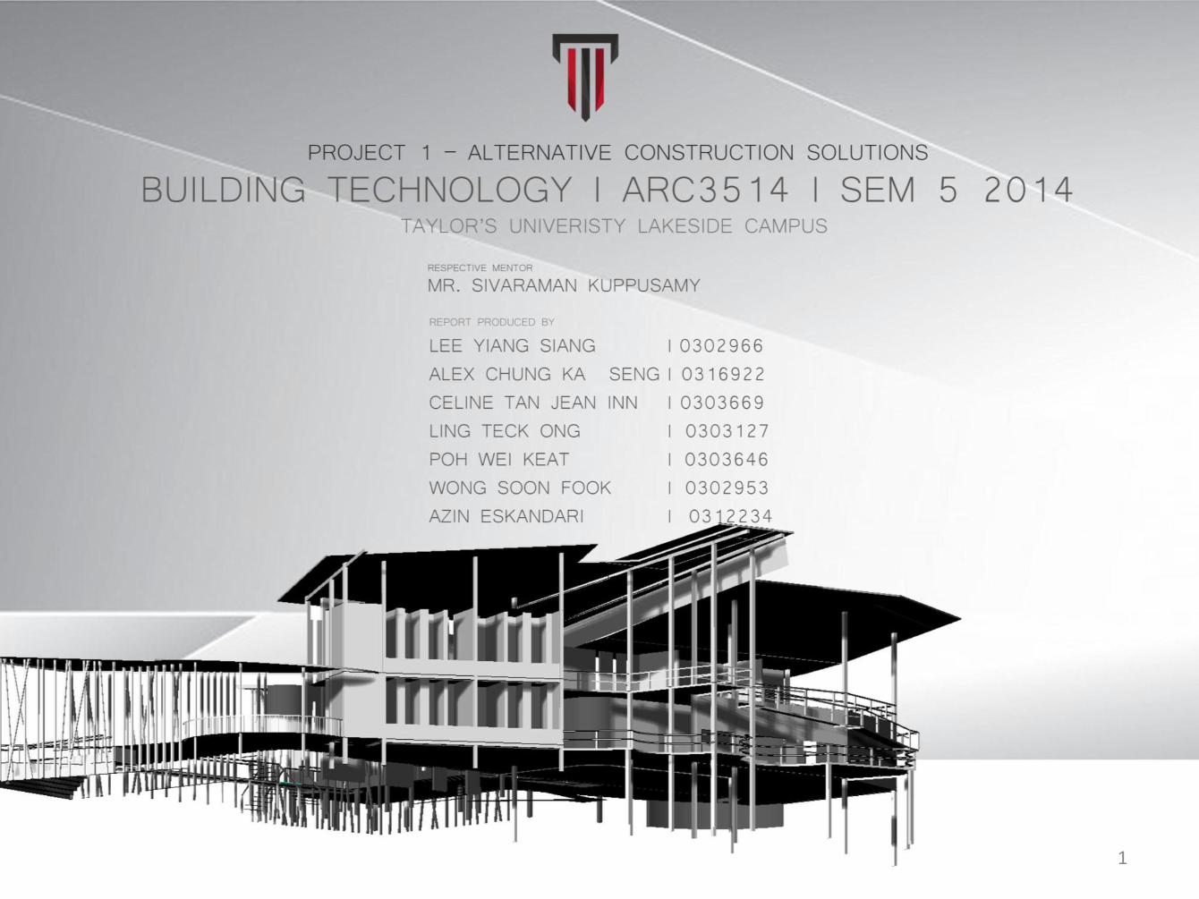
Transcript of Btech compile 6 oct 4am
1

2

2

BASEMENT SYSTEM
Concrete Diaphragm Wall Waterproofing Systems
PRECEDENT STUDY
Diaphragm walls are commonly used in the construction of large commercial
basement. Because of the way these types of wall are constructed, it is only
possible to position the waterproofing on the internal face of the wall.
Waterproofing solutions for these types of wall are therefore similar to those
used to waterproof internal basement walls although they are usually adapted
to take account of the higher levels of water ingress that might be expected in
larger basements.
SECTION A-A, indicates the floor
The Vue shopping mall comprises 7,800 sq.m GFA with 3,850 sq.m NSA with 1
level basement retail area and car parking; four floors retail area including
pedestrian circulation areas, footpaths seating areas. The construction Contract
was awarded mid December 2010 with completion planned 10 months later at
end of October 2011.
The basement works are 100% complete with the exception of the car
access/egress ramp nearing completion. The main M&E plant rooms, waste
water treatment, water storage tanks are complete with M&E works in progress.
Basement masonry walls and architectural works are 70% complete with M&E
works 35% complete.
The superstructure ground and second floor slabs and columns are complete
with third floor slabs 75% complete and forth floor 25% complete.
Lifts, aluminium, glazed windows and shop fronts are under fabrication. Lift
contract is awarded and delivery is due in September 2011.The Basement
Constructed with
Concrete diaphragm wall waterproofing system to maximize the car park
capacity and
prevent the inclement whether to drain out the rainwater efficiency.
VUE Boutique Shopping Mall ,Bangkok
Basement Construction
PR
EP
AR
ED
BY
: AL
EX
CH
UN
G K
AH
SH
EN
G
4

BASEMENT SYSTEM
APPLICATION METHOD
ADVANTAGES - Can be Installed to considerable depth.
- Formation of walls with substantial thickness.
- Flexible system in plan layout.
- Easily incorporated into Permanent works.
- Designable to carry vertical loads.
- Construction time of Basement can be lowered considerably.
- Economic and Positive solution for large deep basement in saturated and
unstable soil profiles.
- Weakness Construction if in very unstable soil profiles below the water
table
- Limited construction time
- Where deeper than normal cantilever support may be required.
DISADVANTAGES
1. Diaphragm walls are constructed by excavating a series of rectangular
panels keyed into each other to form a continuous wall.
4. Panels are keyed into each other by using temporary formwork (stop
ends).
After that, pour in concrete to the formwork and form the basement
diaphragm wall. Finally apply waterproofing membrane to prevent
inclement whether.
3. Water bars (rubber membranes) can also be installed between panels by
casting
in place via the stop end. Excavation of the panels in soils and low
quality rock
are via either rope suspended or kelly bar mounted grabs.
2. Excavation in more competent rock requires mills. In almost all cases the
excavation is supported by drilling fluids such as bentonite or occasionally
polymer slurries. This enables diaphragm walls to be constructed through
almost any ground conditions.
PR
EP
AR
ED
BY
: AL
EX
CH
UN
G K
AH
SH
EN
G
5

BASEMENT SYSTEM
DETAIL WORKING DRAWING
WATERPROOFING SYSTEM FOR BASEMENT DETAIL
1. Insulation Membrane 35mm
2. Insulation 75mm
3. Brick Plug with Compression Seal
4. Plasterboard Dryling 50mm
5. Overseal Tape 75mm
6. Perimeter Drainage
7. Floor Screed- 50mm Min.
8. Insulation Membrane 15mm
9. Knauf Polyfam Floorboard 150mm
10. Membrane (Fill studs with Lean-Mix Concrete)
11. Vandex Super-Used As Lime Control Agent
DETAIL WORKING DRAWING
SEALED INTERNAL BASEMENT WATERPROOFING WITH
AQUADRAIN AND SENTRY SUMP SYSTEM
1. Safeguard Fastframe Dryling System Components
2. Plasterboard -12.5mm
3. Oldroyd Xv membrane 15mm
4. Oldroyd Overseal Tape 75mm
5. Skirting Board
6. Oldroyd Aquadrain
7. Pea Shingle
8. Oldroyd Xv Membrane 15mm
9. Oldroyd Flat Top Aquadrain
PR
EP
AR
ED
BY
: AL
EX
CH
UN
G K
AH
SH
EN
G
6

BASEMENT SYSTEM
DETAIL WORKING DRAWING
WATERPROOFING WITH INTERNAL INSULATION
1. Safeguard Fastframe Drylining System Components
2. Plasterboard 12.5mm
3. Closed Cell Insulation e.g.Knauf
4. Oldroyd Xv membrane
5. Oldroyd Brick Plug with compression seal
6. Oldroyd 75mm Overseal Tape
7. Skirting Board
8. Oldroyd Aquadrain Perimeter Drainage
9. Pea Shingle
10. Closed Cell Insulation e.g Knauf
11. Oldroyd Xv Membrane
12. Flooring Grade 18mm T&G Chipboard
PR
EP
AR
ED
BY
: AL
EX
CH
UN
G K
AH
SH
EN
G
7

RAFT FOUNDATION SYSTEM
RAFT FOUNDATION WITH REINFORCEMENT
PRECEDENT STUDY
A raft foundation consists of a raft of reinforced concrete under the whole of a
building. This type of foundation is described as a raft in the sense that the
concrete raft is cast on the surface of the ground which supports it, as water
does a raft, and the foundation is not fixed by foundations carried down into
the subsoil. Raft foundations may be used for buildings on compressible ground
such as very soft clay, alluvial deposits and compressible fill material where strip,
pad or pile foundations would not provide a stable foundation without
excessive excavation. The reinforced concrete raft is designed to transmit the
whole load of the building from the raft to the ground where the small spread
loads will cause little if any appreciable settlement. SECTION, indicates the foundation
Tugendhat House Details: Barn-style self build, Cambridge shire, November 2009-July 2010
Designer: PJT Design
The main contractor is currently preparing the site to begin casting foundations
for the house. Foundations are a very important part of building design, and the
choice of foundation depends on the soil, the site conditions and the type of
structure that will be built. Foundations carry the load of the entire building and
its contents and must be designed to limit excessive movement in the structure
that may result in it losing its integrity.
Due to the site conditions and the light steel frame structure we have designed
for Stand 47, the foundation type we will be using is a raft foundation. It varies
from the popular strip foundation (which uses unreinforced concrete ground
beams and light brick walls to distribute point loads), in that a raft foundation is
actually a two-way reinforced concrete slab resting on the ground. The raft
distributes pressure from the weight of the structure above to the ground
below, and provides a bound foundation system that reduces the risk of soil
collapse and cracks. The perimeter of the raft is usually turned down to prevent
storm-water from damaging the structure by causing channels below the slab.
Due to the building technology we are using at Stand 47, the raft foundation
offers an alternative to the usual masonry system used in residential
foundations.
8
PR
EP
AR
ED
BY
: AZ
IN E
SK
AN
DA
RI

FOUNDATION SYSTEM
SUPPLIER
PEEL INDUSTRIAL ESTATE
CHAMBERHALL STREET
BURY
LANCASHIRE BL9 0LU
Tel: 0844 576 6726
Fax: 0161 447 8333
REINFORCEMENT DETAIL OF RAFT FOUNDATION
The extensive foundation (which is usually called raft foundation), is a unified
foundation that extends throughout the entire area of the columns.
As a rule, raft foundation is used as a building’s foundation when the soil has a
low bearing capacity.
The behavior of the raft foundation resembles the behavior of a strip
foundation grate.
The stresses applied upon the soil are larger in the columns’ area and lighter in
the intermediate areas. The presence of beams acting as stiffeners helps in a
more even distribution of the soil pressures between the columns’ areas and
the intermediate areas of the raft foundation.
The foundation slabs are reinforced with two wire meshes, one placed at the
lower fibers and one at the upper fibers, by following the reinforcement rules
that apply to slabs.
The beams are reinforced with strong stirrups and bars placed both at the
upper and lower fibers, by following the reinforcement rules that apply to
beams.
The slabs’ free edges are reinforced with common hairpin bars or with a wire
mesh folded like a hairpin, by following the reinforcement rules that apply to
slabs.
When the columns are subjected to large loads and the foundation slab’s
thickness is analogically small, it is obligatory to use punching shear
reinforcement. That reinforcement can be pro-vided by stirrup cages, as it is in
this example, by bundles of properly bent rebar or by special industrial
elements.
The column rebar are in grey color. The red color is reinforcement steel bar.
Reinforcement of a solid raft foundation Raft foundation with punching shear reinforcement
9
PR
EP
AR
ED
BY
: WO
NG
SO
ON
FO
OK
FOUNDATION SYSTEM
APPLICATION METHOD
ADVANTAGES
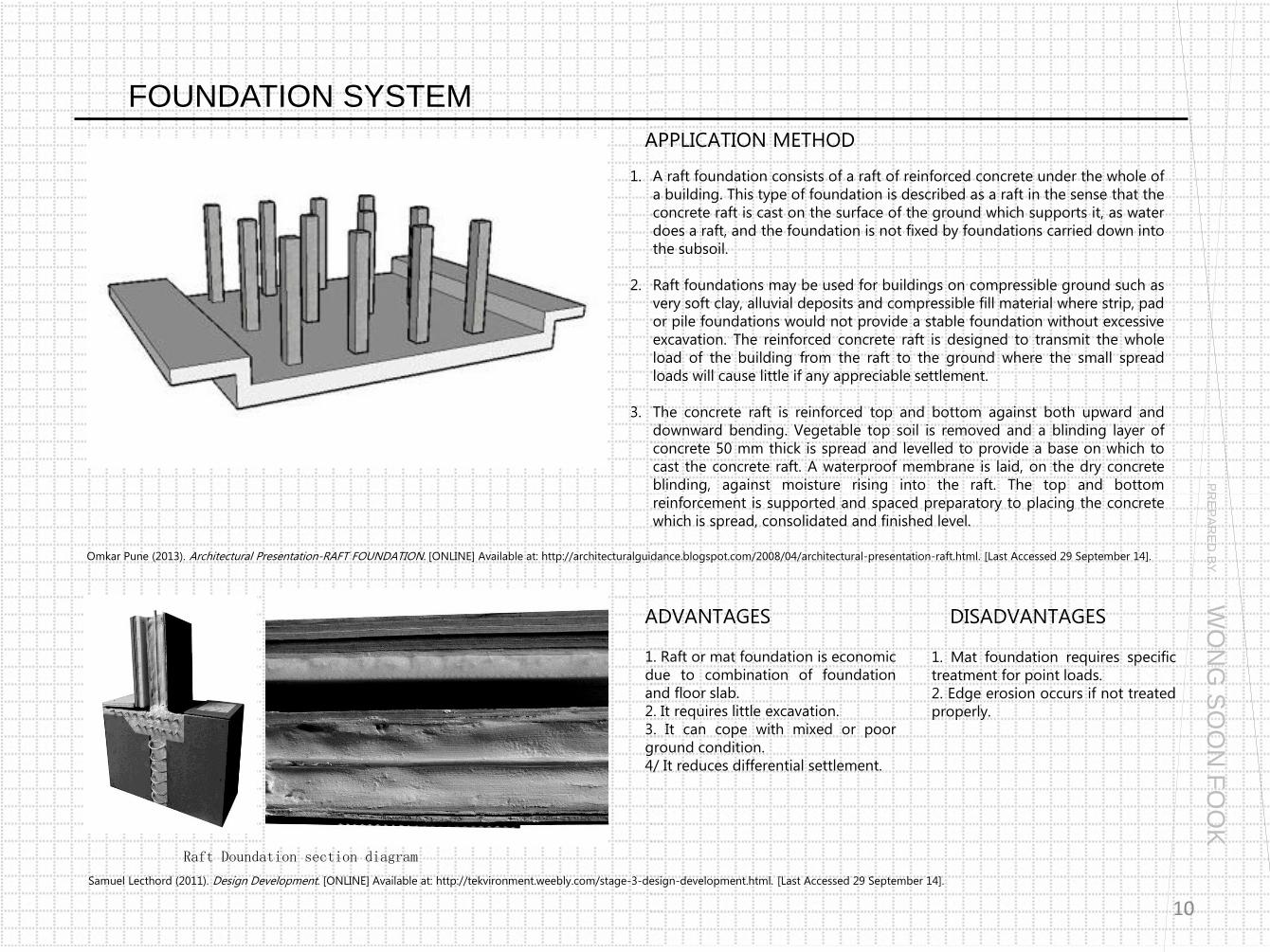
1. A raft foundation consists of a raft of reinforced concrete under the whole of
a building. This type of foundation is described as a raft in the sense that the
concrete raft is cast on the surface of the ground which supports it, as water
does a raft, and the foundation is not fixed by foundations carried down into
the subsoil.
2. Raft foundations may be used for buildings on compressible ground such as
very soft clay, alluvial deposits and compressible fill material where strip, pad
or pile foundations would not provide a stable foundation without excessive
excavation. The reinforced concrete raft is designed to transmit the whole
load of the building from the raft to the ground where the small spread
loads will cause little if any appreciable settlement.
3. The concrete raft is reinforced top and bottom against both upward and
downward bending. Vegetable top soil is removed and a blinding layer of
concrete 50 mm thick is spread and levelled to provide a base on which to
cast the concrete raft. A waterproof membrane is laid, on the dry concrete
blinding, against moisture rising into the raft. The top and bottom
reinforcement is supported and spaced preparatory to placing the concrete
which is spread, consolidated and finished level.
1. Raft or mat foundation is economic
due to combination of foundation
and floor slab.
2. It requires little excavation.
3. It can cope with mixed or poor
ground condition.
4/ It reduces differential settlement.
Raft Doundation section diagram
Omkar Pune (2013). Architectural Presentation-RAFT FOUNDATION. [ONLINE] Available at: http://architecturalguidance.blogspot.com/2008/04/architectural-presentation-raft.html. [Last Accessed 29 September 14].
DISADVANTAGES
1. Mat foundation requires specific
treatment for point loads.
2. Edge erosion occurs if not treated
properly.
Samuel Lecthord (2011). Design Development. [ONLINE] Available at: http://tekvironment.weebly.com/stage-3-design-development.html. [Last Accessed 29 September 14].
10
PR
EP
AR
ED
BY
: WO
NG
SO
ON
FO
OK

FOUNDATION SYSTEM
DETAIL WORKING DRAWING
Step 1: Commonly used type of raft is the solid slab raft without downstand
beam. To begin constructing the solid slab raft foundation, the vegetative top
soil (original soil) is removed then the soil left behind is compressed.
Sometimes, hardcore (broken rocks or stones) maybe be added to raise the
ground floor level.
Step 2: To provide a level bed that will receive the reinforcement and concrete,
a layer of blinding (weak concrete) is added to the surface of the hardcore or
directly to the compacted soil.
Step 3: After the blinding has been allowed to cure for some days, then the
temporary formwork (wood) is then erected over it all around that will serve as
the support to for the reinforced steel bars and concrete work. Mould oil can be
used on the surfaces and sides of the formwork. This makes the finished
concrete work to have a clean look or surface by preventing the concrete from
sticking to the wood used.
Step 4: The reinforced steel bars will then be placed into the formwork
following the bending schedule the structural engineer has provided. After this
is done the concrete which is mixed to a given ratio is then poured in and
spread all over to cover the reinforcement.
When the concrete has been allowed to cure for some days. A layer of damp
proof membrane is spread around the entire area of the foundation and then
over it reinforced mesh wire is laid, which will receive the concrete for the main
floor slab (German floor). Before the concrete is poured all necessary plumbing
piping is done. After the concrete has been cured the main walling for the
building can begin.
STEPS OF RAFT FOUNDATION
Concrete blinding on hardcore Concrete blinding on the soil directly
Temporary frame work Reinforced steel bars Damp Proof Membrane and Mesh Wire Completed raft foundation Completed raft foundation
11
PR
EP
AR
ED
BY
: WO
NG
SO
ON
FO
OK

FOUNDATION SYSTEM
RAFT FOUNDATION SYSTEM DETAIL
12

FOUNDATION SYSTEM
RAFT FOUNDATION SYSTEM DETAIL
13
PR
EP
AR
ED
BY
: WO
NG
SO
ON
FO
OK

BEAM & BLOCK FLOOR SYSTEM
BEAM AND BLOCK SYSTEM
PRECEDENT STUDY
Beam and block is a flooring construction method where concrete blocks are
laid between supporting cast concrete beams. This method can be cost effective
and is also extremely durable. A number of firms specialize in making
components for beam and block flooring and some also provide installation.
One advantage of this technique is relative ease of installation, making it
possible for construction crews without prior experience to establish a sound
floor relatively quickly with some direction.
SECTION A-A, indicates the floor
SUTTERTON SURGERY MEDICAL CENTRE
The works comprise of a new single storey extension and
remodelling to an existing Surgery. Construction methods
include strip foundations, beam and block floors, traditional
cavity wall construction with face brickwork and flat roof.
Aluminum door and UPVC windows. External works include
tarmac to car park, concrete footpath to the perimeter of the
building and extending the existing drainage. New timber
fencing with concrete posts
Flooring Construction of Sutterton Surgery Medical Centre by using beam & block flooring.
PR
EP
AR
ED
BY
: LIN
G T
EC
K O
NG
14

BEAM & BLOCK FLOOR SYSTEM APPLICATION METHOD
Installation It is essential that the floor beams be handled and stacked the correct way up, they should be lifted as
close to the ends as possible and no damaged beams should be used in the installation. It is important
that all mortar in the preceding work is adequately cured, having enough strength to give support to the
floor being installed. Ensure that all mortar and debris is removed from the bearing points and they are
level and true.
PR
EP
AR
ED
BY
: LIN
G T
EC
K O
NG
15
Ventilation Provision should be made for a void beneath the
floor, the depth of which should be at least 150mm
but may vary depending on site conditions. To meet
Local Authority and NHBC requirements, the void
should be ventilated. Ventilation openings should be
placed to enable the free flow of air to the complete
under floor area. Ventilators should be placed
frequently enough to the perimeter of the building to
give suitable ventilation. Supreme supply plastic
telescopic void ventilators with a range of colored
plastic air bricks.

BEAM & BLOCK FLOOR SYSTEM
Ground Floor (Application) Supreme beams are 155mm deep, and
manufactured in two widths with the same side
profile. They are 120mm and 170mm wide. Note!
Wide beams are available at lengths over
4000mm only. They can be used with any
suitable infill block by any manufacturer, subject
to design requirements and specification. The
infill block may be selected to suit budget,
strength or thermal and sound recommendations
as required. Aerated blocks sometimes have a
larger face size than standard blocks. Care must
be taken when the infill block is bedded into a
load bearing wall as the floor blocks must be of
the same crushing strength, or stronger, than the
requirement of the wall.
Upper Floor (Application) Supreme T Beams are also suitable for upper
floors in domestic dwellings where for example
a dense floor is required to create a "quiet
home" or the first floor partitions are to be of
block work, which can be supported by the
floor. Compartment Floors between Dwellings
Specific performance specifications are
required in accordance with the building
regulations in respect of infill blocks and
directly applied screeds.
-Quick and simple installation
-No specialist teams or skills
required. -Minimal excavation of ground
surface, removing the requirement of
importing additional hardstanding
material.
-All weather construction – can be
installed in adverse weather
conditions.
-Flexibility of Design - the high load
carrying capacity allows complete
freedom of room design layouts.
Rigid Floor - without the bounce or
creaking associated with timber
joists.
-Suitable for brown field
developments and ideal on
developments with restricted site
access.
-Services pipe penetrations can be
easily accommodated.
-As soon as the flooring is installed,
the floor can safely be used as a
working platform, allowing the inner
leaf construction work to commence.
ADVANTAGES DISADVANTAGES -The site measurement shall be
accurate other wise precast will not
fit in position
-require heavy lift machines
-the pipes and electric conduits
must be located accurately
PR
EP
AR
ED
BY
: LIN
G T
EC
K O
NG
16

BEAM & BLOCK FLOOR SYSTEM
DETAIL WORKING DRAWING
PR
EP
AR
ED
BY
: LIN
G T
EC
K O
NG
17

WALL SYSTEM
PRECEDENT STUDY / SRISUK VILLAGE, RAYANG
http://www.smartblock.in.th/download/manual/ManSiB_Eng.pdf Retrieved from 1 October 2014
ELEVATION, Indicates the Wall System
Manufacturer: Smart Concrete Co. Ltd
Website : www.smartblock.in.th
Material selection needed to be simple given the impermanence and relatively
Low Budget of the facility. Composite fiber reinforced cement board, a light
weight and economical concrete material, gives the building its clean, simple planes and lines. It is an ideal material choice for this building given the desire
to create large, flat planes that are lightweight, easily dismantled and rebuilt.
The quality of its minimalist details is a tribute to the skill of the crafts people,
and proof that the relatively modest materials can be used to produce refined
result.
Lightweight aggregate concrete
Lightweight aggregate concrete can be produced using a variety of
lightweight aggregates. Lightweight aggregates originate from either:
• Natural materials, like volcanic pumice.
• The thermal treatment of natural raw materials like clay, slate or
shale i.e. Leca.
• Manufacture from industrial by-products such as fly ash, i.e. Lytag.
• Processing of industrial by-products like FBA or slag.
The benefits of using lightweight aggregate concrete include:
• Reduction in dead loads making savings in foundations and reinforcement.
• Improved thermal properties.
• Improved fire resistance.
• Savings in transporting and handling precast units on site.
• Reduction in formwork and propping.
4
2 1
3
1. Insert Tie Bar 2. Install the next row 3. Finish wall with one side plaster 4. Finished wall
PR
EP
AR
ED
BY
: CE
LIN
E T
AN
JE
AN
INN
18

WALL SYSTEM
Poli-Klinik Rüdersdorf bei Berlin
Material: TERRART- Large
Manufacturer: NBK Architectural Terracotta TERRART® -LARGE is an ventilated curtain wall/ rain screen system whose
exposed components are made exclusively from terracotta. This system
components are manufactured so as to maximise shape, accuracy and
guarantee best fit. Terrart also provides large-format elements, which are
individually manufactured based on the project specification. Ideal for
projects where large-sized or oversized elements support wind load and
structural and design aesthetic are a consideration.
Length : max.1800mm. Length of ceramic element can be adjustable.
Height : max. 800mm. Height of the element can be adjustable.
Thickness : approx. 40mm Hollow chambers
Colors : Other colors are available on request.
Glazing according to customer wishes
or RAL specifications
Surface Finishes : Natural, Polished, Tetxured,
Peeled, Profiled, Glazed.
Curved Surface can not be polished
Mass per unit area : approx. 65kg/m2
NBK - Terrart Large. (n.d.). http://www.nbkterracotta.com/en-GB/products/terrart/large.jsp Retrieved October 1, 2014.
Figure: Poli-Klinik Rüdersdorf bei Berlin
Figure: Section dimension of
Terrart-Large
PR
EP
AR
ED
BY
: CE
LIN
E T
AN
JE
AN
INN
Figure: Elevation Drawing of
Polo-Klinik Rudersdort bei Berlin
Advantages: • Strongest compressive strength
and the strongest break load
• Low percentage of water
absorption ensures that dirt
does not penetrate the tile
• Low maintenance material with
an inert material colour
• Outstanding colour consistency
• Recycle content that qualify for
LEEDs credit
• Large tiles enable faster
installation
• Lower labour costs
Key Features: • Wide variety of machining
options available in our
production process
• Able to create individual
facades that meet the toughest
design
• Most common machining
options:
- Horizontal/Vertical/Diagonal
/Mitre Cutes/ Drilling
19
WALL SYSTEM
APPLICATION METHOD
ADVANTAGES
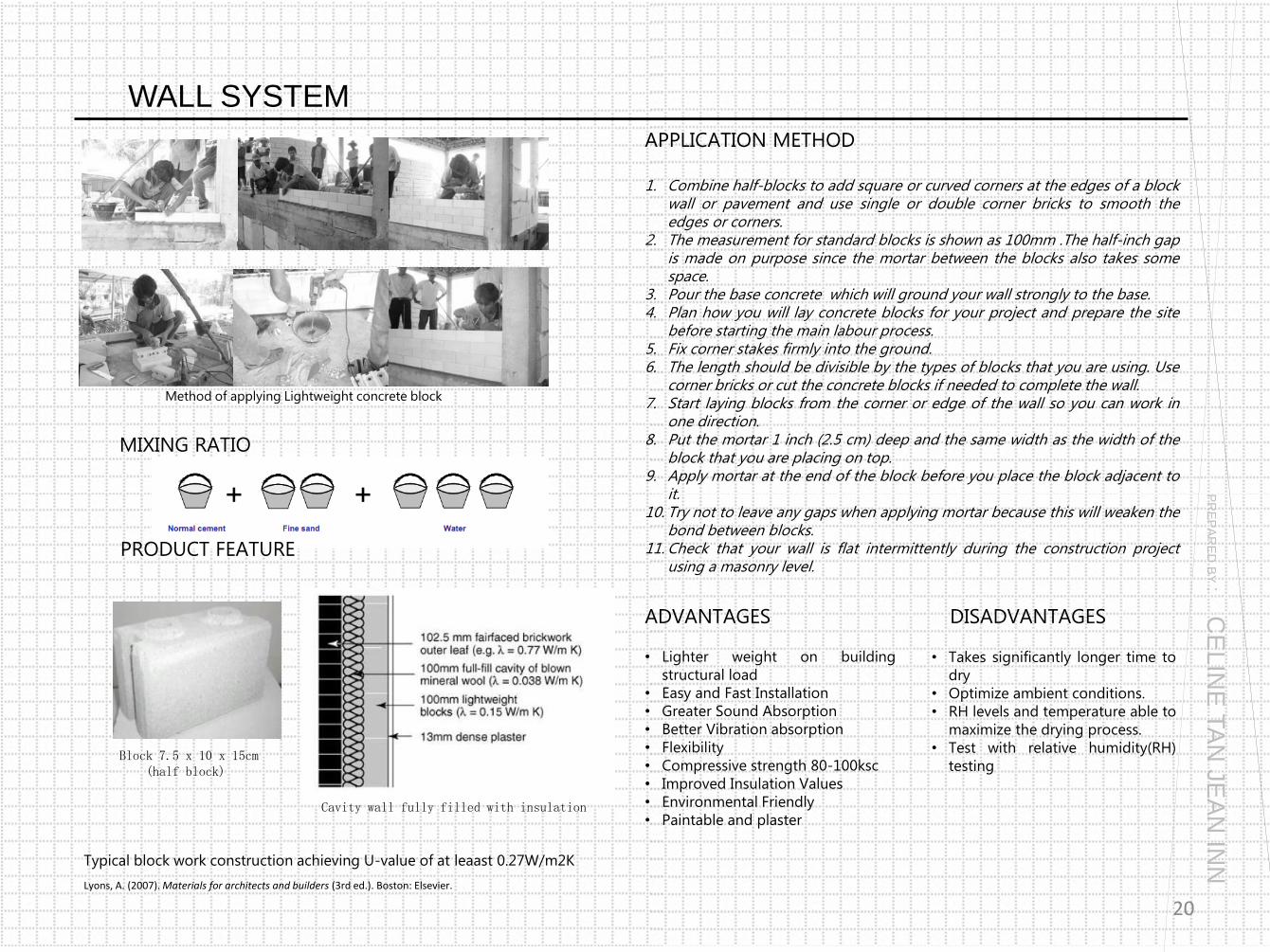
1. Combine half-blocks to add square or curved corners at the edges of a block wall or pavement and use single or double corner bricks to smooth the edges or corners.
2. The measurement for standard blocks is shown as 100mm .The half-inch gap is made on purpose since the mortar between the blocks also takes some space.
3. Pour the base concrete which will ground your wall strongly to the base. 4. Plan how you will lay concrete blocks for your project and prepare the site
before starting the main labour process. 5. Fix corner stakes firmly into the ground. 6. The length should be divisible by the types of blocks that you are using. Use
corner bricks or cut the concrete blocks if needed to complete the wall. 7. Start laying blocks from the corner or edge of the wall so you can work in
one direction. 8. Put the mortar 1 inch (2.5 cm) deep and the same width as the width of the
block that you are placing on top. 9. Apply mortar at the end of the block before you place the block adjacent to
it. 10. Try not to leave any gaps when applying mortar because this will weaken the
bond between blocks. 11. Check that your wall is flat intermittently during the construction project
using a masonry level.
• Lighter weight on building
structural load
• Easy and Fast Installation
• Greater Sound Absorption
• Better Vibration absorption
• Flexibility
• Compressive strength 80-100ksc
• Improved Insulation Values
• Environmental Friendly
• Paintable and plaster
Typical block work construction achieving U-value of at leaast 0.27W/m2K
Lyons, A. (2007). Materials for architects and builders (3rd ed.). Boston: Elsevier.
DISADVANTAGES
• Takes significantly longer time to
dry
• Optimize ambient conditions.
• RH levels and temperature able to
maximize the drying process.
• Test with relative humidity(RH)
testing
MIXING RATIO
PRODUCT FEATURE
Block 7.5 x 10 x 15cm (half block)
Cavity wall fully filled with insulation
Method of applying Lightweight concrete block
PR
EP
AR
ED
BY
: CE
LIN
E T
AN
JE
AN
INN
20

WALL SYSTEM
TERRART LARGE SHADE SCREEN TO LIGHTWEIGHT CONCRETE WALL DETAIL DRAWING
PR
EP
AR
ED
BY
: CE
LIN
E T
AN
JE
AN
INN
21

ROOF SYSTEM
TPO ROOFING
PRECEDENT STUDY
Thermoplastic PolyOlefin (TPO) is a trade name that refers to polymer/filler
blends usually consisting of some fraction of PP (polypropylene), PE
(polyethylene), BCPP (block copolymer polypropylene), rubber, and a
reinforcing filler. Common fillers include, though are not restricted to talc,
fiberglass, carbon fiber, wollastonite, and MOS (Metal Oxy Sulfate). Common
rubbers include EPR (ethylene propylene rubber), EPDM (EP-diene rubber),
EO (ethylene-octene), EB (ethylbenzene), SEBS (styrene-ethylene-butadiene-
styrene). The process of manufacturing TPO requires no plasticizer or
chlorine.
SECTION A-A, indicates the roof
Architecture Lab (2011, March 29). Culloden Battlefield Visitor Centre, Scotland By Gareth Hoskins. Retrieved October 5, 2014, from website: http://architecturelab.net/culloden-battlefield-visitor-centre-scotland-by-gareth-hoskins-architects/
CULLODEN BATTLEFIELD VISITOR CENTRE
Project Details:
Location: Culloden Moor, Inverness – Scotland
Type: Cultural - Public
Architects: Gareth Hoskins Architects
The building form, has a small surface:area ratio to minimize heat loss and
its low form reduces exposure to northerly winds. Orientation and roof form
are manipulated to maximize glare free daylight and natural ventilation. The
roof here functions as an viewing platform colonized by indigenous plants to
retain biodiversity. Roof access is achieved via an 80 metre inclined planted
berm/screen containing site spoil which would otherwise go to landfill.
The roof is a covered with a TPO membrane. More than 1000sqm are used
as a public viewing terrace and are covered with an intensive green roof
system. The under floor heating is powered by a bio fuel boiler fed from the
estates of the local forestry commission. Most of the building is natural
ventilated via roof lights, which also maximize the use of natural light or
high/low level grilles and stack vents.
PR
EP
AR
ED
BY
: PO
H W
EI K
EA
T
22

ROOF SYSTEM
APPLICATION METHOD
ADVANTAGES
Common Applications
• Fully adhered
• Mechanically fastened
• Ballasted
1. TPO is applied in large rolls that vary in both size and thickness.
2. TPO can be fully adhered, mechanically fastened, or ballasted.
3. The seams of the membrane are hot air-welded together to form a very
strong waterproof bond between sheets.
4. Sealing seams to prevent water from entering the welded area through
wicking or capillary action
5. TPO-coated metal flashing material is used to fasten some TPO membranes
at roof edges, walls, decks.
6. Fasteners and plates are used to held the membrane or insulation to the
roof deck.
7. Special screws simplify attachment of roof layers to steel, wood or concrete
decks.
8. Install all membrane flashing at the same time as the roof membrane. (Use
only fully adhered, mechanically attached or prefabricated flashings
depending on job circumstances.)
Method of applying TPO membrane
• Environmentally friendly
• Energy efficient
• Great flexibility even at extremely
low temperatures
• Strong puncture resistant material
• Cool roof Energy Star system UV
resistant, lowers heating and cooling
bills
• Reduces the heat island effect and
solar heat gain
• Resistant to chemicals, acid, salt, oil,
etc.
• Extremely strong seams
Image of material
DISADVANTAGES
• Questionable longevity
(Young roofing technology
which still finding the right
formula to make the product
durable and long lasting while
maintaining a competitive
price)
• Does not stand up well to heat
load
(TPO roofing membranes have
been noted to have an issue of
accelerated weathering when
subjected to high thermal or
solar loading.)
TPO SPECIAL-RESISTANT MEMBRANE
Ledegar Roofing (2014). Flat Roofing Systems for Commercial Buildings. Retrieved October 5, 2014, from Ledegar Roofing website:
https://www.ledegarroofing.com/commercial/flat-roofing
Godfrey Roofing (2013).TPO Roofing. Retrieved October 5, 2014, from Godfrey Roofing Inc website:
http://godfreyroofing.com/commercial/education/roofing-systems/tpo-thermoplastic-olefin/
3 4 5
6 7 8
PR
EP
AR
ED
BY
: PO
H W
EI K
EA
T
23

ROOF SYSTEM
BASE TIE IN WITH HD SEAM PLATE FASTENED TO DECK
GAF (2014). EverGuard® TPO. Retrieved October 5, 2014, from EverGuard website: http://www.gaf.com/Roofing/Commercial/Products/Single_Ply_Roofing/Self_Adhered/Double_Side_and_Strip_In
PR
EP
AR
ED
BY
: PO
H W
EI K
EA
T
24

ROOF SYSTEM
ROOF EDGE GUTTER WITH TPO COATED METAL
Firestone Building Product (2014). Roof Edge Gutter With Flange. Retrieved October 5, 2014, from Firestone website: http://us-fsbp.cbdmarketing.com/technical-information/all-drawings/detail-drawings/tpo-roof-systems/ultrablend-roof-systems/
PR
EP
AR
ED
BY
: PO
H W
EI K
EA
T
25

ROOF SYSTEM
TPO ROOFING JOINED WITH LIGHT WEIGHT CONCRETE WALL
26

27
• Firestone Building Product (2014). Roof Edge Gutter With Flange. Retrieved October 5, 2014, from Firestone website: http://us-fsbp.cbdmarketing.com/technical-information/all-drawings/detail-drawings/tpo-roof-systems/ultrablend-roof-systems/
• Ledegar Roofing (2014). Flat Roofing Systems for Commercial Buildings. Retrieved October 5, 2014, from Ledegar Roofing website:
https://www.ledegarroofing.com/commercial/flat-roofing
• Godfrey Roofing (2013).TPO Roofing. Retrieved October 5, 2014, from Godfrey Roofing Inc website:
http://godfreyroofing.com/commercial/education/roofing-systems/tpo-thermoplastic-olefin/
• Architecture Lab (2011, March 29). Culloden Battlefield Visitor Centre, Scotland By Gareth Hoskins. Retrieved October 5, 2014, from website: http://architecturelab.net/culloden-battlefield-visitor-centre-scotland-by-gareth-hoskins-architects/
• Phillips, D., & Yamashita, M. (2012). Detail in contemporary concrete architecture. London: Laurence King Publishing. • Ching, F. (1975). Building construction illustrated. New York: Van Nostrand Reinhold. • NBK - Terrart Large. (n.d.). http://www.nbkterracotta.com/en-GB/products/terrart/large.jsp Retrieved October 1, 2014.
• http://www.smartblock.in.th/download/manual/ManSiB_Eng.pdf Retrieved from 1 October 2014 • Allen, E., & Iano, J. (2004). Fundamentals of building construction: Materials and methods(4th ed.). Hoboken, N.J.: J. Wiley & Sons.