BST-LT02 DIGITAL MULTIPLE LOOP / PSC / EARTH TESTER · result. When Conducting a test, do not touch...
16
BESANTEK BST-LT02 DIGITAL MULTIPLE LOOP / PSC / EARTH TESTER INSTRUCTION MANUAL Test Equipment Depot - 800.517.8431 99 Washington Street Melrose, MA 02176 TestEquipmentDepot.com
Transcript of BST-LT02 DIGITAL MULTIPLE LOOP / PSC / EARTH TESTER · result. When Conducting a test, do not touch...

BESANTEK
BST-LT02
DIGITAL MULTIPLE
LOOP / PSC / EARTH TESTER
INSTRUCTION MANUAL
Test Equipment Depot - 800.517.8431
99 Washington Street Melrose, MA 02176
TestEquipmentDepot.com
Index 1. Safety Precautions…………..............2. Specifications…………………….......3. Safety Notes………………….............4. Features……………...................……5. Connections………………….............6. Instrument Layout and
System Connections…......................7. Functions………................................8. Preparation for Measurement…….....9. Loop / PSC / Earth testing….............10. Battery……………………..................11. Calibration & Servicing….…..............
Page1-23455
6-8910
11-1213
13-14
-1-
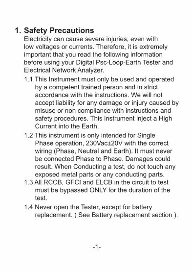
1. Safety PrecautionsElectricity can cause severe injuries, even withlow voltages or currents. Therefore, it is extremelyimportant that you read the following informationbefore using your Digital Psc-Loop-Earth Tester andElectrical Network Analyzer.1.1 This Instrument must only be used and operated
by a competent trained person and in strict accordance with the instructions. We will not accept liability for any damage or injury caused by misuse or non compliance with instructions and safety procedures. This instrument inject a High Current into the Earth.
1.2 This instrument is only intended for Single Phase operation, 230Vac±20V with the correct wiring (Phase, Neutral and Earth). It must never be connected Phase to Phase. Damages could result. When Conducting a test, do not touch any exposed metal parts or any conducting parts.
1.3 All RCCB, GFCI and ELCB in the circuit to test must be bypassed ONLY for the duration of the test.
1.4 Never open the Tester, except for battery replacement. ( See Battery replacement section ).

-2-
1.5 Before use, always inspect the tester and test leads for any sign of abnormal condition or damage. If any abnormal conditions exist (broken test leads, cracked case, display faulty etc…) do not attempt to take any measurement or use the tester. Return it to nearest Distributor for Service.
1.6 The tester has been designed with your safety in mind. However, no design can completely protect against incorrect use. Electrical circuits can be dangerous and/or lethal when a lack of caution or poor safety practice is used. Use caution in the presence of voltage above 24V as these pose a shock hazard.
1.7 Pay attention to cautions and warnings which will inform you of potentially dangerous procedures.

-3-
2. SpecificationsLoop impedance range L-E, L-N 20/200/2000Ω (auto-range)
Loop impedance test current 12A at 230V / 50HzVoltage measurement L-N, L-E 80 to 250V AC/50Hz
Earth wire/path return resistance 20/200/2000Ω (auto-range)
Neutral wire return resistance 20/200/2000Ω (auto-range)Line wire return resistance &transformer windings 20/200/2000Ω (auto-range)
PSC current (L-N) max 3kA
Operating voltage 230V±20V / 50Hz
Typical Accuracy
Loop impedance ±5%rdg ± 2dgtPSC current ±20%rdg ± 5dgt
Voltage ±1%rdg ±1dgtOperating-temperature
-humidity-10°C to 40°C 80% Max.relative humidity
Dimensions 170(L) x 120(W) x 95(D)mmWeight (battery included) Approx. 780gPower source 1.5V (AA) x 8
Safety standard EN 61010-1 CAT III 250VEN 61326-1
Accessories Instruction manual Test leads Shoulder beltBatteries
-
BESANTEK -
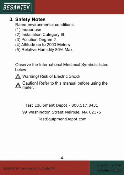
3. Safety NotesRated environmental conditions:(1) Indoor use(2) Installation Category Ill.(3) Pollution Degree 2.(4) Altitude up to 2000 Meters.(5) Relative Humidity 80% Max.
Observe the International Electrical Symbols listed below: A Warning! Risk of Electric Shock
A Caution! Refer to this manual before using the .C. meter.
-4-
Test Equipment Depot - 800.517.8431
99 Washington Street Melrose, MA 02176
TestEquipmentDepot.com
BESANTEK -
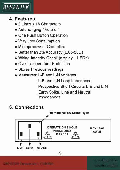
4. Features
• 2 Lines x 16 Characters
• Auto-ranging / Auto-off
• One Push Button Operation
• Very Low Consumption
• Microprocessor Controlled
• Better than 3% Accuracy (0.05-500)
• Wiring Integrity Check (display+ LEDs)
• Over Temperature Protection
• Stores Previous readings
• Measures: L-E and L-N voltages
L-E and L-N Loop Impedance
Prospective Short Circuits L-E and L-N
Earth Spike, Line and NeutralImpedances
5. Connections
International IEC Socket Type
,
I OPERATE ON SINGLE MAX 250V
I I APHASE ONLY
.A
MAX10A 8 CAT.II
; Live Earth Neutral
-5-
BESANTEK
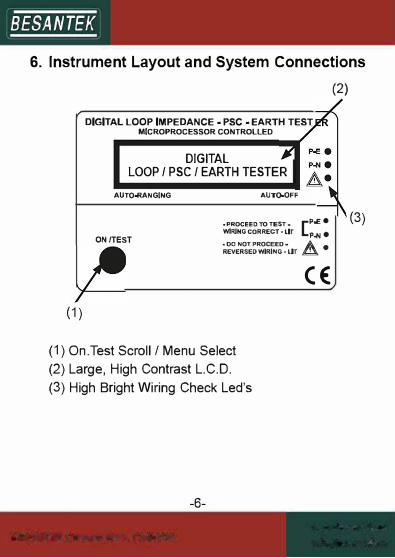
6. Instrument Layout and System Connections
(2)
(1)
DIGITAL LOOP IMPEDANCE • PSC • EARTH TEST MICROPROCESSOR CONTROLLEO
DIGITAL
LOOP / PSC / EARTH TESTER
AUTO-RANGING
ON /TEST
AUTO.OFF
.. PROCEED TO TEST. [ P..E • WIRING CORRECT • LIT p� e .. 00 NOT PROCEED• A e REVERSED WIRING• LIT �
CE:
(1) On.Test Scroll/ Menu Select
(2) Large, High Contrast L.C.D.
(3) High Bright Wiring Check Led's
-6-
(3)

-
BESANTEK -
Fault Finding and Analyzing
the Electrical Network
Electrical Supply and
Distribution
L
E
Point of Test, or
Socket Outlet
VG = Voltage of the generator (supply transformer) (internal impedance of transformer= X-Form)
ZL = Impedance of the Line wire from the transformer, up to the test point (ZL displayed by Instrument also include X-Form). If this impedance is too high, check the connections of the Line wiring, check the quality of the line wiring and the switches/ contacts in the line circuit.
-7-

-8-
ZN = Impedance of the Neutral wire from the transformer, up to the test point. If this impedance is too high, check the connections of the Neutral wiring, check the quality of the line wiring and the switches or contacts in the Neutral circuit.
ZE = Impedance of the Earth wire, including the Earth Impedance itself, as seen by the protection system. Similar checking, specially at the bounding points should be done is this path impedance is too high.
Test Equipment Depot - 800.517.8431
99 Washington Street Melrose, MA 02176
TestEquipmentDepot.com

-9-
7. FunctionsThe tester Measures:● Line – Earth Voltage● Line – Earth Loop Impedance.● Prospective Short Circuit Current L– E.
(This is the current which will flows between Lineand Earth, should a short circuit be made betweenLine and Earth)
● Line – Neutral Voltage● Line – Neutral Impedance● Prospective Short Circuit Current L – N.
(This is the current which will flows between Lineand Neutral, should a short circuit be made betweenLine and Neutral)
● Earth Spike Impedance (Earth Wire)● Line + Transformer Impedance (X-Form)● Neutral Wire Impedance● Wiring Integrity
The tester report:● Low battery indication● Bad wiring● No line● Over-Temperature

-10-
8. Preparation for measurementBefore testing Always check the following.● System Voltage
Your Digital Psc / Loop / Earth Tester is bestintended to work with 230 Vac. However, if thevoltage is lower than that, the test could still bedone but accuracy of the PSC could deterioratedue to the fact that the current injected is lower thanoptimal. However, your tester can work on a widerange of voltage and compute results so that thosechanges have a minimal effect on Results.
● ELCB / RCCB / GFCIIt is necessary to bypass the ELCB / RCCB / GFCIfor the duration of the Earth / Loop / Psc test. UseLeads of same size as ELCB circuit.
● Unplug all LoadIn order not to affect the measurement, it is avoidedto unplug all load from the installation under test.
● Make a clear Sketch of measurement to be able toInterpret results.
● Check leads before using Tester.The Leads Quality and Resistance is a factorinfluence the accuracy of the results make surethey are always in good conditions.
BESANTEK -
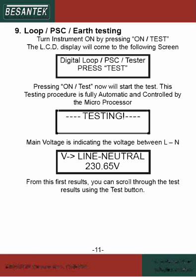
9. Loop / PSC / Earth testingTurn Instrument ON by pressing "ON I TEST"
The L.C.D. display will come to the following Screen
Digital Loop/ PSC I Tester PRESS "TEST'
Pressing "ON / Test" now will start the test. This Testing procedure is fully Automatic and Controlled by
the Micro Processor I ----TESTING!---- IMain Voltage is indicating the voltage between L - N
V-> LINE-NEUTRAL
230.65V
From this first results, you can scroll through the test results using the Test button.
-11-

BESANTEK -
Scroll through the
results again, if the
tester is not
connected to the
circuit under test
or do a new test by connecting the
tester to the circuit
under test.
V-> LINE-EARTH
228.93V
Z-> LINE-EARTH
0.890
Z-> LINE-NEUTRAL
0.430
PSC->LINE-NEUTRAL
536A
PSC->LINE-EARTH
257A
If the circuit under test is open-circuit, the display will
show "NO LINE".
Z-> NEUTRAL WIRE Z-> EARTH WIRE
0.220 0.680
Z-> LINE+XFORM
COIL 0.210
-12-

-13-
10. BatteryBattery Replacement
● The Tester continuously monitors the battery voltage and indicates when the battery need to be replaced.
● The tester’s batteries are situated under the test. ● Disconnect the test leads from the instrument,
remove the battery cover and the batteries. ● Replace with eight 1.5V AA pen light batteries,
taking care to observe correct polarity. ● Alkaline batteries are recommended. ● Replace battery Holder and the battery cover
11. Calibration & ServicingBoth, calibration and servicing must be performed by a competent trained and approved person.Contact your nearest authorized distributor about Calibration Certificate and Servicing.Before returning the Instrument, ensure that:
● the leads have been checked for continuity and signs of damage.
● the batteries are in good condition ● Cleaning and storage:

-14-
WARNINGTo avoid electrical shock or damage to the meter, do not get water inside the case.
Periodically wipe the case with a damp cloth and detergent; do not use abrasive or solvents.If the meter is not to used for periods of longer than 60 days, remove the batteries and store them separately.
Test Equipment Depot - 800.517.8431
99 Washington Street Melrose, MA 02176
TestEquipmentDepot.com


![Enabling Open Innovation in a World of Ubiquitous ...ibis.in.tum.de/mkwi08/...contra_Hypes/...Muhle.pdf · movements like Open Source [Or99][LT02], Open Standards [We04][Pe06], Open](https://static.fdocuments.in/doc/165x107/5f0245cc7e708231d40370ae/enabling-open-innovation-in-a-world-of-ubiquitous-ibisintumdemkwi08contrahypesmuhlepdf.jpg)