BS 2654
111
A BRITISH STANDARD "" Specification for Manufacture of vertical steel welded non-refrigerated storage tanks with butt-welded shells for the petroleum industry BS 2654 : 1989 NO COPYING WITHOUT BSI PERMISSION EXCEPT AS PERMlTI'ED BY COPYRIGHT LAW COPYRIGHT British Standards Institute on ERC Specs and Standards Licensed by Information Handling Services COPYRIGHT British Standards Institute on ERC Specs and Standards Licensed by Information Handling Services
-
Upload
islam-yousef -
Category
Documents
-
view
1.539 -
download
32
Transcript of BS 2654
A BRITISH STANDARD ""
Specification for
Manufacture of vertical steel welded non-refrigerated storage tanks with butt-welded shells for the petroleum industry
BS 2654 : 1989
NO COPYING WITHOUT BSI PERMISSION EXCEPT AS PERMlTI'ED BY COPYRIGHT LAW
COPYRIGHT British Standards Institute on ERC Specs and StandardsLicensed by Information Handling ServicesCOPYRIGHT British Standards Institute on ERC Specs and StandardsLicensed by Information Handling Services
Foreword
I This British Standard was prepared under the direction of the Pressure Vessel Standards Policy Committee and replaces BS 2654 : 1984 which is now withdrawn. It is designed to provide the petroleum industry with tanks of adequate safety, reasonable economy and in a range of suitable capacities for the storage of oil and oil products. The committee recognizes, however, that this standard muld be adopted with equal safety and economy by other industries and/or for the storage of other products, although purchasers and manufacturers may need to formulate and agree additional requirements necessitated by the conditions pertaining to a particular application. NOTE. Users of this British Standard are reminded that the BSI committee responsible is prepared to offer interpretations of the text on request.
The requirements for material selection in this standard have been based on the results of a number of notched and welded Wells Wide Plate Tests (WWP Tests) on carbon and carbon/manganese steel plates, carried out a t the Welding Institute. In particular, the proposals are related to the results reported in 'Mild steel for pressure equipment sub- zero temperatures', British Welding Journal, March 1964. but al l other known W P test data have been taken into account. They also reflect many subjective assessments of practice to date in this field as permitted by current British, American and German codes.
WWP test data all indicate that resistance to brittle fracture is dependent upon the following.
(a) Notch toughness of the material.
(bJ Plate thickness.
(c) Extent of crack-like defects present; it is believed that i f such defects are absent, brittle fracture will not be a problem at normal rates of loading.
(d) Degree of local ernbrittlement a t tip of preexisting defects; in the case of carbon and carbonlmanganese steels, post-weld heat treatment in the stress relieving range temperature is effective in removing severe embrinlement arising as a result of welding and/or flame cutting operations.
The method specified is for determining the notch tough- ness required of a material in any given thickness for design temperatures down to - 10 OC based on tests in which through-thickness defects up to 10 mm long, located both in locally embrittled and post-weld heat treated material, are required to withstand approximately four times yield point strain (see figure 1 ). Scale A is derived using these criteria and data from W P tests for as-welded joints. Scale B is used for determining the requirements for the hydrostatic test. Appendix A gives recommendations for tank foundations and appendix 8 gives recommendations for the design and application of insulation.
This standard is expressed in metric units and a proposed range of standard metric diameters and capacities is given in appendix C.
All pressure and vacuum values in this standard are expressed as gauge values.
The symbols used throughout the tex t are as listed in appendix D.
Appendix E gives recommendations for internal floating covers, appendix F gives recommendations for the design of venting systems and appendix G offers seismic loading I provisions.
It has been assumed in the drafting of this British Standard that the execution of i t s provisions is entrusted to appro- priately qualified and experienced people.
This edition introduces technical changes to bring the standard up-to-date but it does not reflect a full review of the standard, which will be undertaken in due course.
Compliance with a British S u d a d does not of itself confer immunity from legal obligations.
COPYRIGHT British Standards Institute on ERC Specs and StandardsLicensed by Information Handling ServicesCOPYRIGHT British Standards Institute on ERC Specs and StandardsLicensed by Information Handling Services
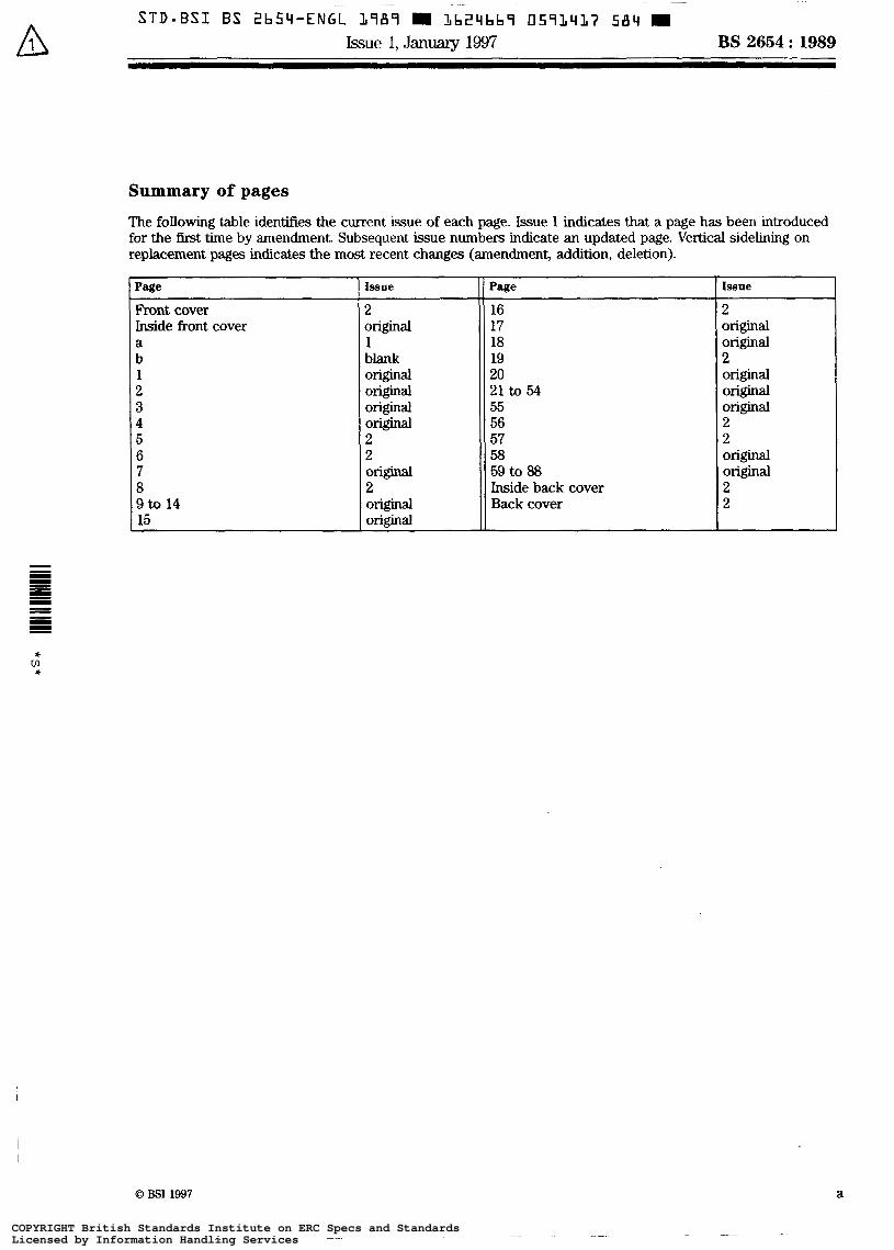
Summary of pages
The following table identifies the current issue of each page. Issue 1 indicates that a page has been introduced for the first time by amendment. Subsequent issue numbers indicate an updated page. Vertical sidelining on replacement pages indicates the most recent changes (amendment, addition, deletion).
Page
Front cover Inside front cover a b 1 2 3 4 5 6 7 8 9to 14 15
Issue
2
1 blank
original
original original Original Original 2 2 Original 2 I 1 Original Original
Pace Issue
16 2 17
20 2 19 Original 18 original
Original 55 Original 21 to 54 Original
56 2 57 2
58 original 59 to 88 Original
Inside back cover 2 Back cover 2
0 BSI 1997 a
COPYRIGHT British Standards Institute on ERC Specs and StandardsLicensed by Information Handling ServicesCOPYRIGHT British Standards Institute on ERC Specs and StandardsLicensed by Information Handling Services
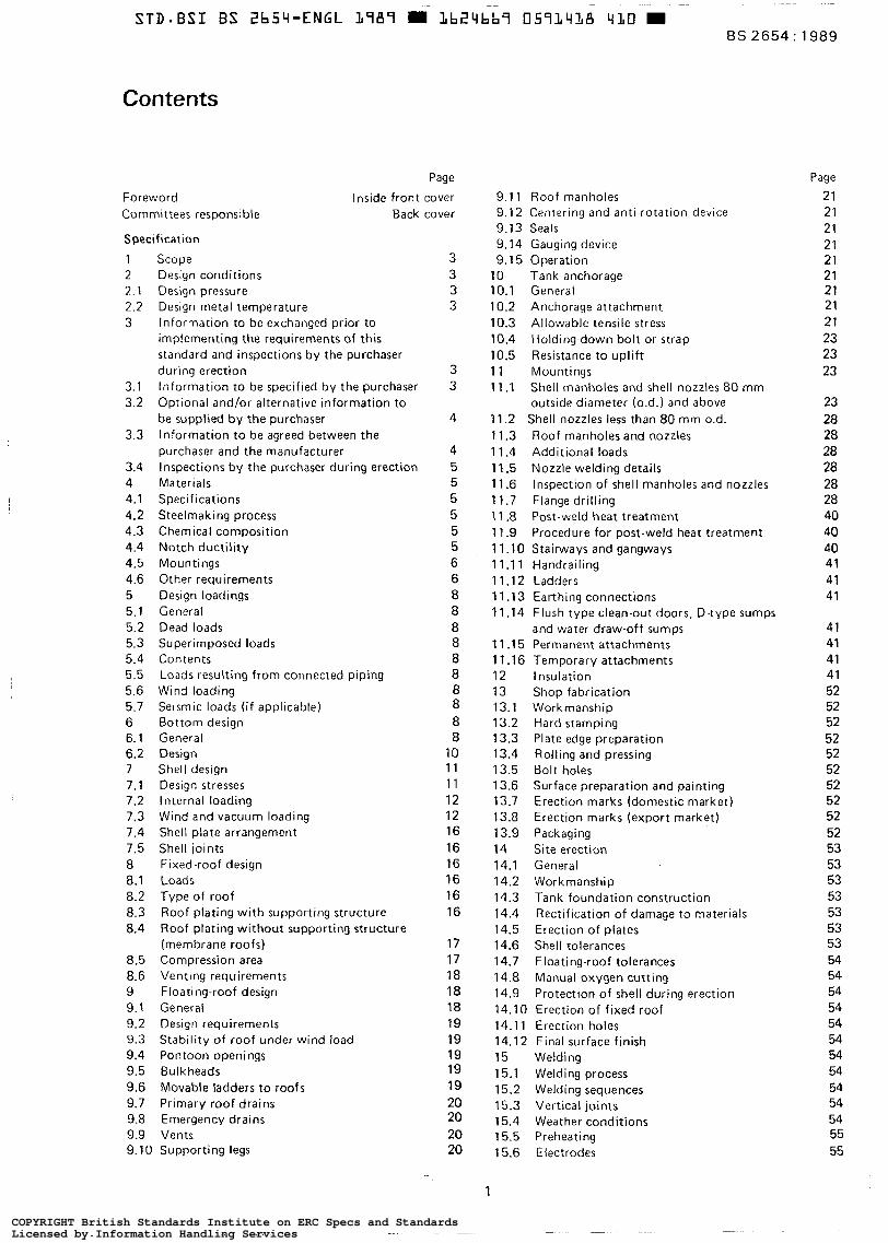
Contents
Specification
1 2 2 .1 2.2 3
3.1 3.2
3.3
3.4 4 4.1 4.2 4.3 4.4 4.5 4.6 5 5.1 5.2 5.3 5.4 5.5 5.6 5.7 6 6.1 6.2 7 7.1 7.2 7.3 7.4 7.5 8 8.1 8.2 8.3 8.4
8.5 8.6 9 9.1 9.2 9.3 9.4 9.5 9.6 9.7 9.8 9.9
Scope Design conditions Design pressure Design metal temperature Information to be exchanged prior to implementing the requirements of this standard and inspections by the purchaser during erection Information to be specified by the purchaser Optional and/or alternative information to be supplied by the purchaser Information to be agreed between the purchaser and the manufacturer Inspections by the purchaser during erection Materials Specifications Steelmaking process Chemical composition Notch ductility Mountings Other requirements Design loadings General Dead loads Superimposed loads Contents Loads resulting from connected piping Wind loading Selsmic loads ( i f applicable) Bottom design General Design Shell design Design stresses Internal loading Wind and vacuum loading Shell plate arrangement Shell joints Fixed-roof design Loads Type of roof Roof plating with supporting structure Roof plating without supporting structure (membrane roofs) Compression area Venting requirements Floating-roof design General Design requirements Stability of roof under wind load Pontoon openings Bulkheads Movable ladders to roofs Primary roof drains Emergency drains Vents
9.10 Supporting legs
3 3 3 3
3 3
4
4 5 5 5 5 5 5 6 6 8 8 8 8 8 8 8 8 8 8
10 11 11 12 12 16 16 16 16 16 16
17 17 18 18 18 19 19 19 19 19 20 20 20 20
~~
Page
Foreword Inside front cover Committees responsible Back cover
Page
9.1 1 Roof manholes 21 9.12 Centering and anti-rotation device 21 9.13 Seals 21 9.14 Gauging device 21 9.15 Operation 21
10 10.1 10.2 10.3 10.4 10.5 11 11.1
11.2 11.3 11.4 11.5 11.6 11.7 1 1.8 1 1.9 11.10 11.11 11.12 11.13 11.14
11.15 11.16 12 13 13.1 13.2 13.3 13.4 13.5 13.6 13.7 13.8 13.9 14 14.1 14.2 14.3 14.4 14.5 14.6 14.7 14.8 14.9
Tank anchorage General Anchorage attachment Allowable tensile stress Holding-down bolt or strap Resistance to uplift Mountings Shell manholes and shell nozzles 80 mm outside diameter (o.d.1 and above Shell nozzles less than 80 mm 0.d. Roof manholes and nozzles Additional loads Nozzle welding details Inspection of shell manholes and nozzles Flange drilling Post-weld heat treatment Procedure for post-weld heat treatment Stairways and gangways Handrailing Ladders Earthing connections Flush type clean-out doors, D-type sumps and water draw-off sumps Permanent attachments Temporary attachments Insulation Shop fabrication Workmanship Hard stamping Plate edge proparation Rolling and pressing Bolt holes Surface preparation and painting Erection marks (domestic market) Erection marks (export market) Packaging Site erection General Workmanship Tank foundation construction Rectification of damage to materials Erection of plates Shell tolerances Floating-roof tolerances Manual oxygen cutting Protection of shell durinq erection
14.10 Erection of fixed roof 14.11 Erection holes 14.12 Final surface finish 15 Welding 15.1 Welding process 15.2 Welding sequences 15.3 Vertical joints 15.4 Weather conditions 15.5 Preheating 15.6 Electrodes
1
21 21 21 21 23 23 23
23 28 28 28 28 28 28 40 40 40 41 41 41
41 41 41 41 52 52 52 52 52 52 52 52 52 52 53 53 53 53 53 53 53 54 54 54 54 54 54 54 54 54 54 54 55 55
COPYRIGHT British Standards Institute on ERC Specs and StandardsLicensed by Information Handling ServicesCOPYRIGHT British Standards Institute on ERC Specs and StandardsLicensed by Information Handling Services
BS 2654: 1989
Page
15.7 Tack welds 15.8 Cleaning of welds 15.9 Back gouging and chipping 15.10 Visual inspection 15.1 1 Weld reinforcement 15.12 Undercutting 15.13 Peening 15.14 Repairs 16 Welding procedure and welder approval 16.1 General 16.2 Welding procedure approval 16.3 Approval process for welders 17 Radiography 17.1 Application 17.2 Preparation for examination 17.3 Extent of radiography per tank 17.4 Radiography procedure 18 Testing 18.1 General 18.2 Bottom testing 18.3 Mountings 18.4 Shell testing 18.5 Floating-roof testing 18.6 Fixed-roof testing
Appendices
A Recommendations for tank foundations B Recommendations for the design and application
of insulation C Standard diameters for vertical cylindrical tanks D List of symbols E Recommendations for internal floating covers F Recommendations for the design of venting
systems I G Seismic provisions for storage tanks
Tables
1 Leg length of fi l let weld 2 Minimum specified shell thickness 3 Angle ring dimensions 4 Minimum sizes of top curb angle 5 Manhole and nozzle body thickness 6 Extent of radiography per tank 7 Acceptance levels for radiographic examination 8 Standapd lengths for shell plates 9 Nominal capacities of standard vertical
cylindrical tanks
I I 1 Soil profile coefficient 10 Requirements for emergency venting
Figures
1 Minimum Charpy V impact requirements 2 Typical bottom layouts for tanks 3 Cross joints in bottom plates where three
thicknesses occur 4 Typical joints in sketch plates under shell
plates: tanks up to and including 12.5 m diameter
5 Typical annular plate joint under shell plates: tanks over 12.5 m diameter
6 Wind girders 7 Shell-roof compression areas 8 Typical tank anchorage detail 9 Shell manholes
55 55 55 55 55 55 55 55 56 56 56 57 57 57 57 57 58 59 59 59 59 60 60 60
61
64 75 77 78
80 83
10 11 14 18 23 58 59 75
75 82 85
7 9
10
1 1
11 13 17 22 24
10 Shell insert type reinforcement 11 Barrel type nozzle reinforcement 12 Graph for the determination of the thickness
of barrel type nozzle reinforcement 13 Flanged roof nozzles 14 Typical weld details for connection of
mountings: set-through type (preferred details): r = 20 mm (max.)
mountings: set-through type (preferred details): 20 mm t < 40 mm
mountings: set-through type (preferred details): t i > 40 mm
17 Typical weld details for the connection of mountings: set-through type (alternative details)
mountings: compensated set-through type (preferred details): t = 12.5 mm (max.)
mountings: compensated set-through type (preferred details)
mountings: dompensated set-through type (alternative details)
mountings: set-on type (shell nozzles less than 80 mm 0.d.)
mountings
15 Typical weld details for connection of
16 Typical weld details for connection of
18 Typical weld detai ls for connection of
19 Typical weld details for connection of
20 Typical weld details for connection of
21 Typical weld details for connection of
22 Recognized weld details for connection of
23 Reinforcement detai ls for low type nozzles 24 Details of overlay weld for nozzles 25 Details of an acceptable type of spiral stairway 26 Handrailing 27 Typical detail of earthing boss (supplied with
28 Flush type clean-out door with insert plate
29 Flush type clean-out door with plate
30 Flush type clean-out door with plate
31 Davit for 915 m m x 1230 mm clean-out door 32 Combined water draw-off and clean-out sump 33 Acceptable water draw-off sumps 34 Location of Charpy V-notch impact t e s t
specimen 35 Typical tank foundation 36 Pad supports 37 Angle section and plate supports 38 Typical flanged nozzle or manhole 39 Typical arrangement showing termination of
40 Typical arrangement with insulation attached
41 Typical flanged nozzle or manhole with
42 Typical construction of insulation local to
43 Effective masses 44 Centroids of seismic forces 45 Factor K, 46 Compressive force wb
tank) site welded to tank shell plates
reinforcement
reinforcement 915 mm x 1230 mm
reinforcement 300 mm x 1230 mm
insulation adjacent to the tank bottom
to the shell only
additional branch insulation
wind stiffening ring
2
Page
25 26
27 29
30
31
32
33
34
34
35
36
37 38 39 42 43
44
45
47
48 49 50 51
56 62 67 67 68
70
70
71
72 84 84 85 87
COPYRIGHT British Standards Institute on ERC Specs and StandardsLicensed by Information Handling ServicesCOPYRIGHT British Standards Institute on ERC Specs and StandardsLicensed by Information Handling Services
~-
BS 2654 : 1989
Specification
1 Scope
This British Standard specifies requirements for the materials, design, fabrication, erection and testing of
I vertical cylindrical welded non-refrigerated steel tanks. The standard applies specifically to the needs of the petroleum industry and the requirements for the design, construction, inspection and testing of tank shells apply when the design relative density of the product stored will not be less than 1 .O. NOTE I . Thls provldes the petroleum Industry with the necessary operational flexibility in that tanks originally designed to store one partlcular product can subsequenrly be utilized to store products of differlng relative densities when the need arises.
1 The standard applies to non-refrigerated storage tanks with the following characteristics:
(a) maximum design pressure o f 56 mbar*;
(b) design metal temperature not cooler than - 10 O C ;
(c) that are never filled above the level of the top of the cylindrical shell or the overflow, whichever i s lower.
NOTE 2 . For special cases outside the scope of this specificatlon where the design pressure lies between 56 mbar and 140 mbar, reference may be made to BS 4741 for types of roof design procedures.
In addition to the definitive requirements, the standard also requires the items detailed in clause 3 to be docu- mented. For compliance with this standard, both the definitive requirements and the documented items have to be satisfied. NOTE 3. The titles of the publications referred to in this standard are listed on the inside back cover,
2 Design conditions
2.1 Design pressure (see 3.l(e))
2.1.1 General. In the interests of standardization of design pressures, storage tanks shall be grouped as specified in 2.1.2 to 2.1.4.
2.1.2 Non-pressure tanks. Non-pressure tanks shall be suitable for working a t atmospheric pressure, but designed for an internal pressure of 7.5 mbar and a vacuum of 2.5 mbar. In a l l cases the tanks shall comply with 8.5. For tanks with column-supported roofs, an internal pressure of 4 mbar shall be assumed.
2.1.3 Low-pressure tanks. Low-pressure tanks shall be designed for an internal pressure of 20 mbar and a vacuum of 6 mbar.
2.1.4 High-pressure tanks. High-pressure tanks shall be designed for an internal pressure of 56 mbar and a vacuum of 6 mbar.
2.2 Design metal temperature (see 3 . l ( f ) )
The design metal temperature shall be specified by the purchaser on the basis of the official weather reports over at least 30 years. The design metal temperature shall be the lower o f the lowest daily mean temperaturet plus 10 O C and the minimum temperature of the contents.
For a storage tank constructed for service in the UK where the shell temperature is controlled by ambient conditions, the minimum design metal temperatureshall not exceed 0°C.
For a storage tank constructed for use outside the UK and where no long term data or weather reports are available, the design metal temperature shall be the lower of the lowest daily mean temperaturet plus 5 'C and the minimum temperature of the contents. In the interests of operational flexibility, the minimum design temperature for the tank shall not take into account the beneficial e f fec t of heated or insulated tanks.
3 Information to be exchanged prior to implementing the requirements of this standard and inspections by the purchaser during erection
3.1 Information to be specified by the purchaser*
The following basic information to be specified by the purchaser shall be fully documented. Both the definitive requirements specified throughout the standard and the documented items shall be satisfied before a claim of compliance with the standard can be made and verified.
(a) Geographical location of the tank
(b) Diameter and height or the capacity of the tank, including ullage. Where only the capacity of the tank is specified ground conditions shall be included.
(c) Whether fixed or floating roof i s to be supplied and the type of roof if the purchaser has specific preferences, ¡.e. for fixed roofs (cone, dome, membrane, etc.) or for floating roofs (pontoon, double deck, etc.).
(dl All relevant properties of the contained fluid, including the relative density and corrosion allowance (if, how and where required).
(e) The design vapour pressure and vacuum conditions inside the tank (see 2.1).
( f ) The minimum and maximum design metal tempera- tures (see 2.2) .
(9) The size, number and type of a l l mountings required showing locations. Maximum filling and emptying rates and any special-venting arrangements (see 9.9). (h) The minimum depth of product (see 10.1 (b)).
( i ) If the tank is to be insulated (see clause 12).
'1 rnbar = 100 Nlm' = 100 Pa. t lmaximum temperature + minimum temperature). i Where the word 'purchaser' occurs in the text, it i s intended to include representatives of the purchaser. e .g . purchaser's inspector.
3 COPYRIGHT British Standards Institute on ERC Specs and StandardsLicensed by Information Handling ServicesCOPYRIGHT British Standards Institute on ERC Specs and StandardsLicensed by Information Handling Services
BS 2654 : 1989
( J ) Areas of responsibility between the designer, the manufacturer and the erector of the tank when these are not the same.
(k) Quality of the water (particularly i f inhtbiters are to be present) to be used during tank water test (see 18.4.2).
(I) Expected maximum differential settlements during water testing and service lifetime of the tank (see appendix A). (m) Other specifications which are to be read in conjunction with this standard.
3.2 Optional and/or alternative information to be supplied by the purchaser
The following optional and/or alternative information to be supplied by the purchaser shall be fully documented. Both the definitive requirements specified throughout this standard and the documented items shall be satisfied before a claim of compliance with the standard can be made and verified.
(a) Whether a check analysis is required (see 4.3.2).
(b) Whether the weight of insulation is excluded from the minimum superimposed loadings (see 5.3.2).
(c) Whether significant external loading from piping, etc. i s present (see 5.5).
(d) Whether seismic loading is present requiring specialist consideration including methods and criteria to be used
(e) Whether a fixed roof is required and i f so:
I in such analysis (see 5.7 and appendix G),
( 1 ) i f cone roof slope is other than 1 in 5 (see 8.2.2); (2) if radius of curvature of dome roof is other than 1.5 times tank diameter (see 8.2.2);
(3) whether made as a double-welded lap joint or a butt joint (see 8.3.5); (4) whether particular venting requirements are specified (see 8.6.1 and 8.6.2).
or (f) Whether a floating roof is required and if so:
(1 1 whether floating roof is designed to land as part of the normal operating procedure (see 9.1.1);
(2) whether floating roof is designed for wind-excited fatigue loading (see 9.3);
(3) whether top edge of bulkhead is to be provided with continuous single fi l let weld (see 9.51;
(4) floating roof ladder details (see 9.6.1, 9.6.2 and 9.6.4);
(5) type of primary roof drains (see 9.7.1);
(6) requirements for additional roof manholes (see 9.1 1);
(7) whether maximum aromatic content of the product is greater than 40 % ( r n / r n ) (see 9.13);
(8) requirements for the design of gauge hatch (see 9.14).
(9) An alternative type of manhole cover (see 11.3). (h) Details of flange drilling i f not in accordance with BS 1560 (see 11.7).
( i) Detailsof painting requirements and whether pickling, grit or shot blasting i s required (see 13.6.1, 13.6.3 and 14.12).
( j ) Details of erection marks (see 13.7.1).
(k) Whether welding electrodes and/or key plating equipment are to be supplied by the tank manufacturer (see 14.1).
(I) Alternative arrangements for provision of tank foundation (see 14.3).
(m) Whether a welder making only f i l let welds is required to be approved for such welding in accordance with BS 4871 : Part 1 (see 16.3.2).
(n) Whether tack wetding of shell, roof and bottom i s permitted t o be carried out by non-approved operators (see 16.3.2).
3.3 Information to be agreed between the purchaser and the manufacturer
The following information to be agreed between the purchaser and manufacturer shall be f u l l y documented. Both the definitive requirements specified throughout this standard and the documented items shall be satisfied before a claim of compliance with the standard can be made and verified.
(a ) Alternative materials selection (see 4.1)
(b) Precautions for avoiding brittle fracture during hydrostatic testing (see figure 1 ) .
(c) Alternative bottom plate layouts (see 6.1.2).
(dl Spacing of the roof-plate-supporting members for dome roof (see 8.3.11.
(e) Any increase in roof joint efficiency for lapped and welded roof plates (see 8.3.6).
( f ) Alternative loading conditions for floating roof design (see 9.2.1.4).
(9) The operating and cleaning position levels of the supporting legs (see 9.10.1).
(h) Proposed method to hold the plates in position for welding (but see 14.5.1).
(i) The location and number of checks on shell tolerances during erection (see 14.6.2). ..
( j ) Methods of protecting the shell during erection against wind damage, etc. (see 14.9).
(k) If fixed roofs are to be erected in the tank bottom, and raised into position by an air pressure or suitable means (see 14.10).
(I) Sequence in which joints are to be welded (see 15.2).
(m) If previously approved appropriate welding procedures are acceptable (see 16.1.3).
(n) Test procedures to be used during the tank water test (see 18.1.1).
4
COPYRIGHT British Standards Institute on ERC Specs and StandardsLicensed by Information Handling ServicesCOPYRIGHT British Standards Institute on ERC Specs and StandardsLicensed by Information Handling Services
A Issue 2, January 1997
3.4 lnrprctianr by the purchaser during erection lhe following inspections by the purchaser during erection shall be fully documented. Both the definitive require- ments spacified throughout this standard and the docu- mented items s h a l l be satisfied before a claim of compliance with this stMdrrd can be d e and verified.
(a) Rectifkation’of damage to materials prior to erection (see 14.4). (b) Repair of all unaoceptable defects found in welds (soe 15.14.1 l. (c) Addi t io~l radiowaphic testing of welds bee 15.149). (dl Records of each welder’s approval (see 16.3.5.1). (e) Standard test radiograph (see 17.4.4). (0 Repair of leaks in bottom and bottom to shell welds (see 182.41. (91 Leaks in pontoon compartments and decks (see 18.5.31.
4 Materials
4.1 Sprciticrtknr AI1 mrtcr i r ls used in the mufacturn of tanks complying with this st8d.d shall be in accordance with appropriate rpccifiitions given in either (8) ar (b), a d as amended or amplified by the requirements of th is &dard.
I (a) plrtes* in BccoTd8m with BS EN 10025 and BS EN 101 13
Forgings: in ac#)rdllnce with 6s 1503 (CS-
60lting mtabl: in d a n a with BS 1506
rectiomand bars: ( I s 0 630-1980.)
and carbodmanganese steets only)
Piping: in accordance with BS 3602 and 0s 3603.
(bl Otherwise suitable matcnials weed between the purchaser and the manufacturer CICC 3.3(a)) provided that ruch materials are equivalent in heat treatment and chemical composition to thosa l i in (al and, in other respects, comply with all the requirements of this SUndrrd.
NOTE. Exænples we fominpr in .&ordlnce with ASTM A105 : lS82t. piping in accordme8 with ASTM A106 : 1982t o r ASTM AS24 : 1-t O( G n d a A 8 d B of API SL : 1983t.
4.2 Smtmaking p o c a s Steels shall be made by the open hearth, electric furnace or one of the basic oxygen processes. Use of semi-killed or fully-killed steels shall be permitted provided that they comply with all the requirements of this standard. Neither
BS 2654 : 1989
Bessemer steel- nor rimming steel shall be permitted to be used. The tank manufacturer s h a l l ascertain from the steelmaker (at the time of order) the condition of supply of all plates, e.g. as-rolled, normalized, or quenched and tempered, and the nominal composition of thc steel.
4.3 Chemical mmporition
4.3.1 The carbon equivalent calculated from the ladle analysis usiq the following formula shall not exceed 0.43 % b / m ) for plates 20 mm thick up to and including 25 mm nor 0.42 % (m/m) for plater thicker than 25 mm.
Mn Cr+Mo+V + Ni+- 6 5 15
c + - +
4.32 Thc Id le analysis and chedc analysis, when rcquired (see 32(a)), shall be reported by the s tee l maker IL requircd by the particular steel specification togcther with values for all elements specified in 43.1 and including any deliberate additions, e.g. aluminium, niobium, boron or vanadium. In a check analytls the carbon equinlent, using the formula C + Mn/6 shall not e x c d 0.43 % (m/m) (see 3.2(a)). The incidence of testing shall not be l e s s than that specified in BS EN 10025. I 4.3.3 For steels with specified minimum tensik strength greater thsn 420 Wmm’ the phorphorus plus the sulphur shall not exceed 0.08 % (#?/m).
43A Steels shall be rithw aluminium treated with a minimum aluminium/nitrogen ratio of 2:1 or have a nitrogen content of kss than 0.01 % (m/m).
4.4 Notch ductilb
4.4.1 Gened. The raquired impact test tempernwes md levels of impact propmiss f o r shdl and bottom annular plates shall amply with the following dauses; as appro- priate, -her wim 6.1.4 and figure 1 :
ia) dause 4-42 for materials 430 Wmm’ tensile strength; (b) dause 4.4.3 for materials > 430 Wmm’ and
(c) dause 4.4.4 for materials > 490 Wmm’ tensile strength.
490 Wmm2 tensile strength;
For thicknesses not exceeding 13 mm in materials with specified minimum tensile strengths up to and induling 490 Wmm’. impact tests a n not required. NOTE. Steels mry be supplied in canditiona other thon normdired when it ir to be damafutmtd to the m i d r t i o n of th. purchmer that ma manufacturing pmadum (O.% controlled rolling, q u w h - ing and tmparing. œeekmd coding, ah.) wit1 provide oquident notch ductilify.
O BSI 1997 5
COPYRIGHT British Standards Institute on ERC Specs and StandardsLicensed by Information Handling ServicesCOPYRIGHT British Standards Institute on ERC Specs and StandardsLicensed by Information Handling Services
STD-BSI BS 2b54-ENGL L789 I L b 2 4 h b 9 0593423 888 m Issue 2, January 1997
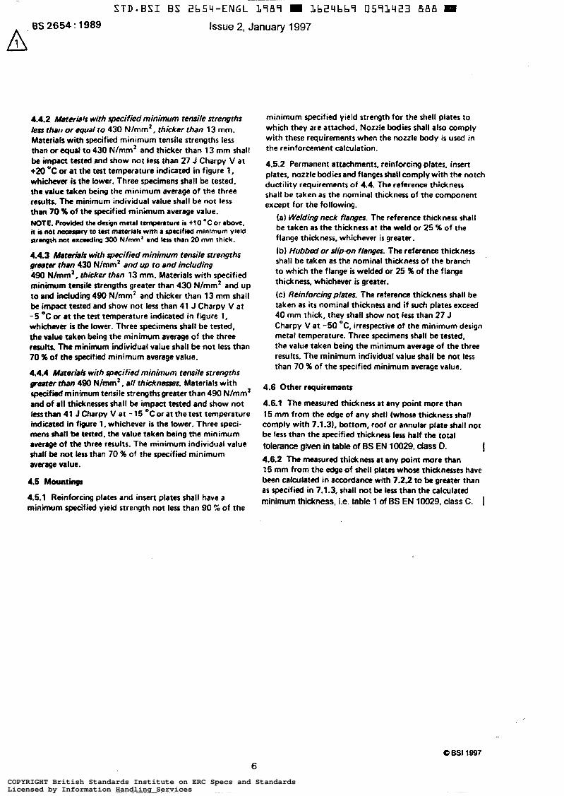
4.4.2 Mater& with specift%d minimum tensile strengths less that1 or equal to 430 Nlmm’ , thicker than 13 mm. Materials with specified minimum tensile strengths less than W equal to 430 Nlmm’ and thicker than 13 mm shall be impact tested and show not less than 27 J Charpy V at +m ‘C or a t the test temperature indicated in figure I, whichever is the tower. Three specimens shall be tested, the value taken being the minimum average of the three results. The minimum individual value shall be not less than 70 %of the specified minimum average value. NOTE. Provided the design metal temporarum ir +10 *C or above. it b W necessary so test materials with a specified minimum yield n r q r h not e d i n g 300 Nimm' and ksr than 20 mm thick.
4.4.3 hfatmtbls with specified minimum tensile strengths p a t e r than 430 N/mm2 and up to and including 490 N/mm’, thicker than 13 mm. Materials with specified minimum tensile strengths greater than 430 N/mm2 and up to and induding 490 N/mm2 and thicker than 13 mm shall be impact tested and show not less than 41 J Charpy V at -5 OC or at the test temperature indicated in figure I, whichever is the lower. Three specimens shall be tested, the va& taken being the minimum average of the three results. l h e minimum individual value shall be not less than 70 % of the specified minimum average value.
4.4.4 Marsrids with specified minimum tensile strengths parer than 490 N/mm2, all thicknesses. Materials wi th s p e c i f i d minimum tensile strengthsgreattr than 490 N/mm2 and of all thicknesses shall be impact tested and show not less than 41 J Charpy V at - 15 O C or at the test temperature indicated in f w r e l . whichever is the lower. Three speci- mens shall be tested, the value taken being the minimum rverrw of the three results. The minimum individual value shall be not less than 70 % of the specified minimum average value.
4.5 Mountings
4.5.1 Reinforcing plates and insert plates shall have a minimum specified yield strength not less than 90 % of the
minimum specified yield strength for the shell plates to which they are attached. Nozzle bodies shall also comply with these requirements when the nozzle body is used in the reinforcement calculation.
4.5.2 Permanent attachments, reinforcing prates, insert plates. nozzle bodies and flanges shall comply with the notch ductility requirements of 4.4. The reference thickness shall be taken as the nominal thickness of the component except for the following.
(a) Weldingneck flanges. The reference thickness shall be taken as the thickness at the weld or 25 % of the flange thickness, whichever is greater.
{b) Hubbed or slipon flanges. The reference thickness shall be taken as the nominal thickness of the branch to which the flange is welded or 25 %of the flange thickness, whichever is greater.
(cl Reinforcingplates. The reference thickness shalt be taken as i ts nominal thickness and if such plates exceed 40 mm thick, they shall show not less than 27 J Charpy V a t -50 OC, irrespective of the minimum design metal temperature. Three specimens shall be tested, the value taken being the minimum average of the three results. The minimum individual value shall be not less than 70 % of the specified minimum average value.
4.6 Other requirements
4.6.1 The measured thickness at any point more than 15 mm from the edge of any shell (whose thickness shall comply with 7.1.31, bottom, roof or annular plate shall not be less than the specified thickness l e s half the total tolerance given in table of BS EN 10029, dass D. 4.6.2 The measured thickness at any point more than 15 mm from the edge of shell plates whore thicknesses have been calculated in accordance with 7.22 to be greater than as specified in 7.1.3, shall not be less than the calculated minimum thickness, ¡.e. table 1 of BS EN 10029, dass C. I
I
6 BSI 1997
6 COPYRIGHT British Standards Institute on ERC Specs and StandardsLicensed by Information Handling ServicesCOPYRIGHT British Standards Institute on ERC Specs and StandardsLicensed by Information Handling Services
A BS 2654: 1989
Scale B Scale A
Scale A -Minimum design meta l tempera ture O C (see 2 . 2 1
. .
. . , , W . . . I . . . . I . . . / I . . . . I
r . . . I . . . . J . . .:Y... . I . . ._ I
- 20
- 15
- 12.5
Charpy V tes t t empera tu re O C
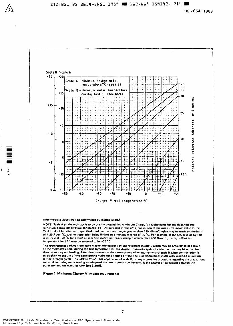
(Intermediate values may be determined by interpolation.)
NOTE. Scale A on the ordinate is to be used in determining minimum Charpy V requirements for the thickness and minimum design temperature concerned. For the purpo~s of this note, conversion of the measured impact value to the 27 J (or 41 J for steels w i th spacified minimum tensile strength greater than 430 N/mm'j -lue may b e made on the basis of 1.35 J per "C. such extrapolation being limited to a maximum range of 20 "C. For exemple. i f the actual value b y test IS 33.75 J at -2O'C for a steel of specified minimum tensile strength greater than 400 Nlmm' . the equivälent test temperature for 27 J may be assumed to be -25 O C .
The requirements derived from Kale A take into account an improvement in safety which may be anticipated as a re$& of the hydrostatic test. During the fint hydrostatic test the degree of security against brittle fracture may be rather lm than on subsequent loading. Attention ir drawn to the more conservative requirements of =ale B when consideration is to be given to lhe use of this scale during hvdrastatic testing of tank shells constructed of steels with specified minimum tensile strength greater than 430 Nlmrn' . The application of scale B. or any alternative procedure regarding the precautions
purchaser and the manufacturer (see 3.3(bl). Io b e taken during waler testing t o safeguard the tank from bri t t le fracture, is the subject of agreement betwaen the
Figure 1. Minimum Charpy V impact requirements
7
COPYRIGHT British Standards Institute on ERC Specs and StandardsLicensed by Information Handling ServicesCOPYRIGHT British Standards Institute on ERC Specs and StandardsLicensed by Information Handling Services
BS 2654 : 1989
A
~~ ~
STD-BSI BS 2b54-ENGL L989 L b 2 4 b b 9 U59L425 b5O ~~~
Issue 2, January 1.997
5 Design loadings
5.1 Ganerd The tank shall be designed for the most severe possible combination of the loadings specified in 5.2 to 5.7.
5.2 Dud loads Dead loads shall be considered as those resulting from the weight of all component parts of the tank.
5.3 Superimposed buis
5.3.1 The fixed roof and supporting structures shall be designed to support a minimum superimpored load of 1.2 kN/m2 of projected area. The superimposed load shall be the sum of either internal vacuum and snow load, or internal vacuum and live load.
5.3.2 Unless otherwise specified by the purchaser (see 32(b)), the weight of any insulation shall be included in the mínimum superimposed loadings for fixed roofs specified in 5.3.1.
5.3.3 The superimposed loadings applied to floating roofs shall be as specified in clause 9.
5.4 Contents
The t o a d due to the contents shall be the weight of the product to be stored from full to empty, with or without the specified vapour pressure. For the design of the shell, the product relative density shall be assumed to be not less than 1.0.
5.5 Loads resulting from connected piping Pipes, valves and other items connected to the tank shell shall be designed in such a manner that no significant additional loads or moments are applied to the tank shell.
Settlement of all pipe support foundations relative to those of the tank, rotational and translational movements of the &wert shell course shall be taken into consideration. The purchaser shall state whether this loading is significan1 bee 331~)). otherwise it shall not be taken into account.
5.6 Wind Wing The wind speed used in the calculations shall be the maximum three second gust speed estimated to be exceeded on the average only once in 50 years.
In the UK this value shall be taken as effective ‘wind speed’ as defined in BS 6399 : Part 2. In other areas the I
three second gust speed shali be obtained from the appro- priate authority. NOTE. Careful consideration should be given to open-top water tanks without any form of roof s i n c c wind effects could produce severe movement of the contents resulting in spillage and excesswe loading on the tank. If this W i n g cannof be quantified. it ir recommended that a roof be provided unless previous experience with similar conditions h a proved satisfactory.
5.7 Seismic loads (if applicable1 The purchaser shall specify whether the tank i s to be designed to withstand seismic loads (see 32(dI). NOTE. Recommendations on seismic provisions for s t o m p tanks are given in appendix G.
6 Bottom design
6.1 General
6.1.1 Full support of the tank bottom by the foundation shall be assumed. NOTE. Recornmendations for tank faundations and typical tank pads are given in appendix A.
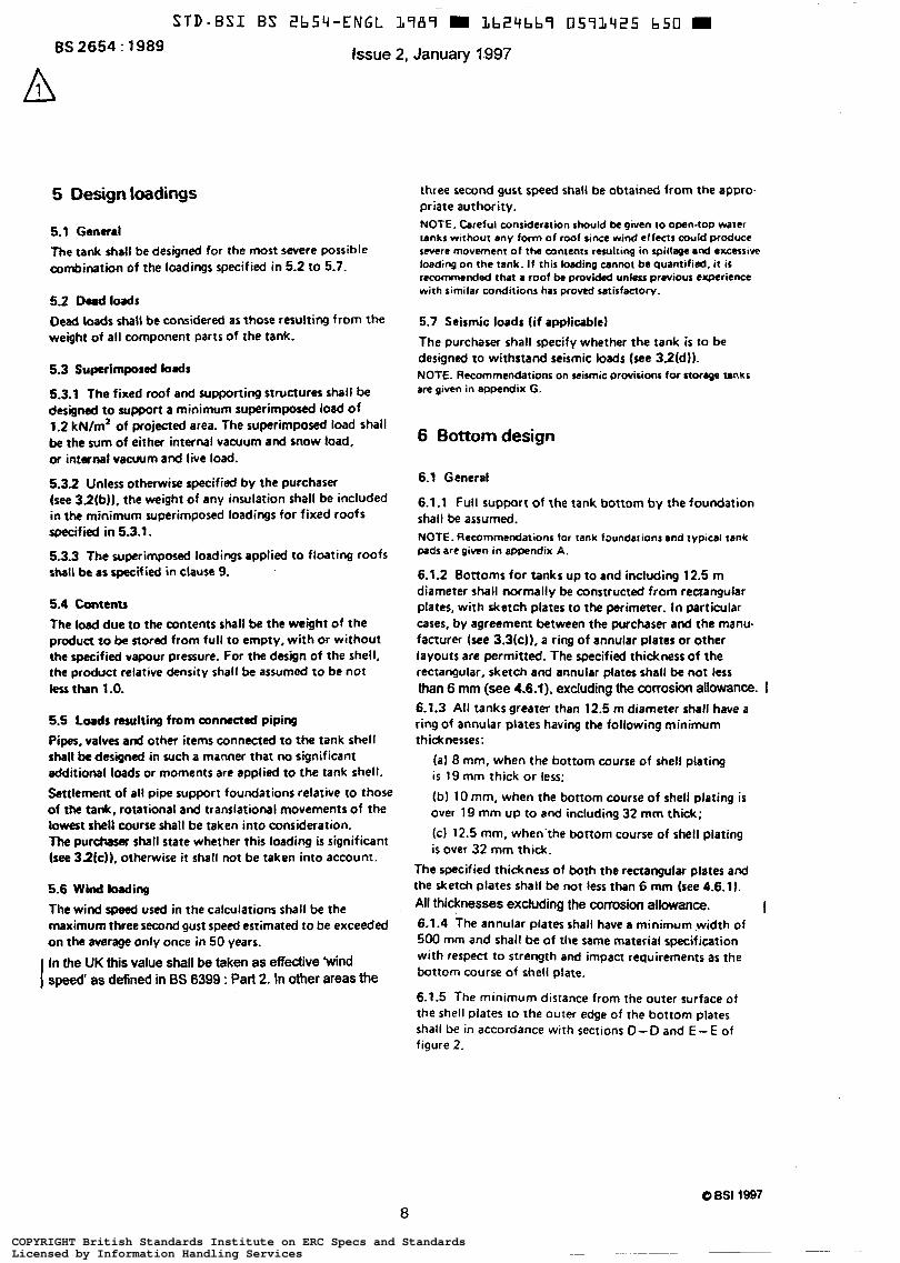
6.1.2 Bottoms for tanks up to and including 12.5 m diameter shall normally be constructed from rectangular plates, with sketch plates to the perimeter. ln particular cases, by agreement between the purchaser and the manu- facturer (see 3.3k)). a ring of annular plates or other layouts are permitted. The specified thickness of the rectangular, sketch and annular plates shall be not less than 6 mm (see 4.6.f), excluding the WKOSiOn allowance. I 6.1.3 All tanks greater than 12.5 m diameter shall have a ring of annular plates having the following minimum thicknesses:
(al 8 mm, when the bottom course of shell plating i s 19 mm thick or less;
(b) 10 mm, when the bottom course of shell plating is over 19 mm up to and including 32 mm thick; (cl 12.5 mm. when~the bottom course of shell plating ir over 32 mm thick.
The specified thickness of both the rectangular plates and the sketch plates shall be not less than 6 mm (see 4.6.1). All thicknesses excluding the corrosion allowance. I 6.1.4 The annular plates shall have a minimum width of 500 mm and shall be of the same material specification with respect to strength and impact requirements as the bottom course of shell plate.
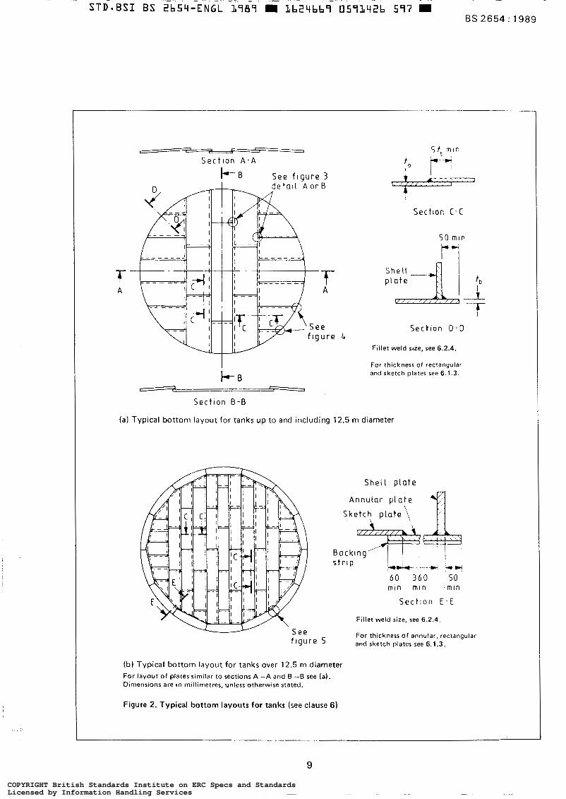
6.1.5 The minimum distance from the outer surface of the shell Plates to the outer edge of the bottom plates shall be in accordance with sections 0-0 and E-E of figure 2.
a O BSI 1997
COPYRIGHT British Standards Institute on ERC Specs and StandardsLicensed by Information Handling ServicesCOPYRIGHT British Standards Institute on ERC Specs and StandardsLicensed by Information Handling Services
I
S e c t l o n A - A
I+-B S e e f l g u r e 3
S t , mln
T b p-
Sec t l on C - C
5 0 m l n
S e c t l o n 0 - 0
Fillet weld size, see 6.2.4.
For thickness of rectangular and sketch plates see 6.1.3.
r I
Sec t ron B - B
(al Typical bottom layout for tanks up to and including 12.5 m diameter
f tgur e 5
(b) Typical bottom layout for tanks over 12.5 m diameter For layout of plates similar to sections A-A and B "B see (a). Dimensions are in millimetres, unless otherwise stated.
Figure 2. Typical bottom layouts for tanks (see clause 6)
Fillet weld size, see 6.2.4.
For thickness of annular, rectangular and sketch plates see 6.1.3.
9
COPYRIGHT British Standards Institute on ERC Specs and StandardsLicensed by Information Handling ServicesCOPYRIGHT British Standards Institute on ERC Specs and StandardsLicensed by Information Handling Services
BS 2654 : 1989
6.2 Design
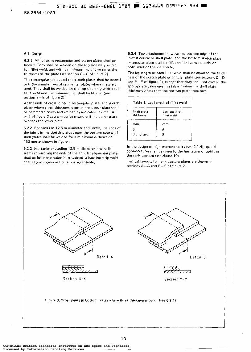
6.2.1 All joints in rectangular and sketch plates shall be lapped. They shall be welded on the top side only with a full fillet weld, and with a minimum lap of f ive times the thickness of the plate (see section C-C of figure 2).
The rectangular plates and the sketch p la tes shall be lapped over the annular ring of segmental plates where these are used. They shall be welded on the top side only with a full f i l let weld and t h e minimum lap shall be 60 mm (see section E - E of figure 2). At the ends of cross joints in rectangular plates and sketch plates where three thicknesses occur, the upper plate shall be hammered down and welded as indicated in detail A or B of figure 3 as a corrective measure i f the upper plate overlaps the lower plate.
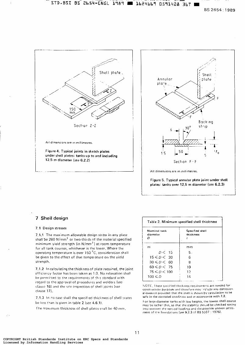
6.2.2 For tanks of 12.5 m diameter and under, the ends of the joints in the sketch plates under the bottom course of shell plates shall be welded for a minimum distance of 150 mm as shown in figure 4.
6.2.3 For tanks exceeding 12.5 m diameter. the radial seams connecting the ends of the annular segmental plates shall be full penetration butt-welded; a backing strip weld of the form shown in figure 5 is acceptable.
6.2.4 The attachment between the bottom edge of the lowest course of shell plates and the bottom sketch plate or annular plate shall be fillet-welded continuously on both sides of the shell plate.
The leg length of each fillet weld shall be equal to the thick- ness of the sketch plate or annular plate (see sections D-D snd E - E of figure 21, except that they shall not exceed the appropriate value given in table 1 when the shell plate thickness i s less than the bottom plate thickness.
I Table 1. Leg length of fillet weld
Shell plate thickness
6 and over
Leg length of fillet weld
mm
6 8
In the design of high-pressure tanks (see 2.1.4), special consideration shall be given to the limitation of uplift in the tank bottom (see clause 10). Typical layouts for tank bottom plates are shown in sections A-A and B - B of figure 2.
Sectlon X - X
DetaI I B
izz%%ïa Sect lon Y - Y
Figure 3. Cross joints in bottom plates where three thicknesses occur (see 6.2.1)
10
COPYRIGHT British Standards Institute on ERC Specs and StandardsLicensed by Information Handling ServicesCOPYRIGHT British Standards Institute on ERC Specs and StandardsLicensed by Information Handling Services
. ..
~
STD-BSI B S 2bS4-ËÑGL 3787 m Lb24bb7 0573428 3bT .. - . . ~. .. . . - ..~_ .. . _ ~ - L > - ~ -
BS 2654: 1989
/ '
S e c t l o n Z - Z
All dimenslons are in millimetres.
Figure 4. Typical joints in sketch plates under shell plates: tanks up to and including 12.5 m diameter (see 6.2.2)
7 Shell design
7.1 Design stresses
7.1.1 The maximum allowable design stress in any plate shall be 260 N/mm* or two-thirds of the material specified minimum yield strength ( in Nimm2) a t room temperature for all tank courses, whichever i s the lower. Where the operatlng temperature is over 150 O C , consideration shall be given to the effect of that temperature on the yield strength.
7.1.2 In calculating the thickness of plate required, the joint efficiency factor has been taken as 1 .O. No relaxation shall be permitted !o the requirements of t h i s standard with regard to the approval of procedures and welders (see clause 16) and the s i t e inspection of shell joints (see clause 17).
7.1.3 In no case shall the specified thickness of shell plates be less than i s given in table 2 (see 4.6.1).
The maxlmurn thickness of shell plates shall be 40 mm.
Section F - F
All dimensions are in millimetres.
Figure 5. Typical annular plate joint under shell plates: tanks over 12.5 m diameter (see 6.2.3)
Table 2. Minimum specified shell thickness
Nominal tank thickness diameter Specified shell
t D
m
5 . D < 15
mm
1 5 < D < 30
12 75 < D < 100 10 6 0 Q D < 75 8 3 0 d D < 60 6
100 S D 14 ___ "_
NOTE. These specified thickness requlrernents are needed for COnstrUcf~on purposes and therefore may include any corrosion allowance provided that the shell is shown by calculation to be safe in the corroded condition and In accordance wi th 7.2.
For large<liameter tanks with low herghts, the lowest shell course may be rather thln, so that the stability should be checked taking into account the vertlcal loadings and the possible uneven settle- ment of the foundations (see 9.2.3 of ß S 5387 : 1976).
1 1 COPYRIGHT British Standards Institute on ERC Specs and StandardsLicensed by Information Handling ServicesCOPYRIGHT British Standards Institute on ERC Specs and StandardsLicensed by Information Handling Services
BS 2654 : 1989
7.2 Internal loading
7.2.1 The tank shell thickness shall be computed on the assumption that the tank is filled either to the top of the shell or to the overflow designed to limit the fluid height. When the height of the shell includes a wind skirt with overflow openings and/or seismic freeboard, the maximum product height for calculation purposes shall be the over- flow height or the height less the seismic freeboard. The calculation shall be based on the relative density of the stored product and this shall not be less than 1 .O.
7.2.2 The following formula shall be used in calculating the minimum thickness t (in mm) of shell plates (see 4.6.2):
= - { 9 8 w ( H - 0.3) + P ) + C O
20s where
H i s the distance from the bottom of the course under consideration to the height defined in 7.2.1 (in m);
is the tank diameter (in m);
is the maximum density of the contained liquid under storage conditions, but shall not be less than 1 .O (in g/mL);
is the allowable design stress (see 7.1) (in N/mm* );
is the design pressure (this can be neglected for non-pressure tanks) (in mbar);
is the corrosion allowance (in mm).
7.2.3 The tension force in each course shall be computed a t 0.3 m above the centre line of the horizontal joint in question, except when adjacent upper and lower courses are inade from materials with different mechanical properties and :
H, - 0.3 HL - 0.3 > S" S,
where
Hu i s the distance from the bottom of the upper course
Su is the allowable design stress of the upper course
H, is the distance from the bottom of the lower course
S, i s the allowable design stress of the lower course
to the height defined in 7.2.1 (in m);
(in N/mm2);
to the height defined in 7.2.1 (in m);
(in N/mm2 );
then the thickness of the upper course shall be calculated using the modified formula:
t = - (98wH + P ) f C. D
20s Furthermore, no course shall be constructed a t a thickness less than that of the course above, irrespective of the materials of construction.
7.3 Wind and vacuum loading
7.3.1 Primary wind girders
7.3.1.1 Open-top tanks shall be provided with a primary stiffening ring to maintain roundness when the tank i s subjected to wind loads. The primary ring shall be located a t or near the top of the top course and preferably on the outside of the tank shell.
7.3.1.2 Fixed-roof tanks with roof structure are considered to be adequately stiffened a t the top of the shell by the structure, and a primary ring i s not therefore considered necessary.
7.3.1.3 The requircd minimum section modulus of the primary stiffening ring Z (in cm3) shall be determined by the equation":
Z = 0.0580'H where
D i s the diameter of the tank (tanks in excess of 60 m in diameter shall be considered to be of this dimen- sion when determining the section modulus) (in m);
H i s the height of the tank shell including any 'freeboard' provided above the maximum filling height (see 7.2.1) (in m).
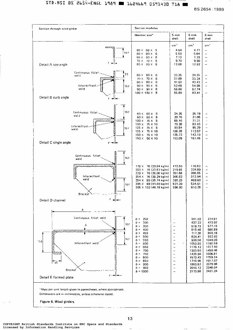
7.3.1.4 The section modulus of the primary stiffening ring shall be based upon the properties of the applied members. NOTE 1. I t may include a portion of the tank shell for a distance of 16 plate thicknesses below and, where applicable, above the ring shell attachment.
When curb angles are attached to the top edge of the shell ring by butt welding, this distance shall be reduced by the width of the vertical leg of the angle. NOTE 2. Section moduli values for typical ring members are gwen in figure 6.
7.3.1.5 Stiffening rings shall comprise:
(a) structural sections or formed plate sections; or (b) sections built up by welding; or (c ) combinations of such types of sections assembled by welding.
NOTE. The outer periphery of stiffening rings may be circular or polygonal.
7.3.1.6 The minimum size of angle for use alone, or as a component in a built-up stiffening ring, shall be 60 mm x 60 mm x 5 mm. The minimal nominal thickness of plate for use in formed or built-up-stiffening rings shall be 5 mm when i t s width does not exceed 600 mm and shall be 6 mm if over 600 mm wide.
7.3.1.7 When stiffening rings are located more than 600 mm below the top of the shell, the tank shall be provided with a 60 mm x 60 mm x 5 mm top curb angle for 5 mm top shell course and 80 mm x 80 mm x 6 mm angle for top shell course 6 mm and thicker.
12 COPYRIGHT British Standards Institute on ERC Specs and StandardsLicensed by Information Handling ServicesCOPYRIGHT British Standards Institute on ERC Specs and StandardsLicensed by Information Handling Services
Section through wind girder 7
Detai l A t o p angle
Detai l B curb angle
Contlnuous f i l l e t - ve ld
lntermlt tent 1 1 6 , ve ld
t 4 L -
a t v e l d
lntermlt ve ld
tent
A 716 f
ØJ-
Detai l C single angle
Detai l [ 3
t
channel
b e 7
i Contlnuous f l l let veld
Brockeí L ..--", ---
f Detai l E formed plate
'Mass per unit length given in parentheses, where appropriate
Dimensions are ln millimetres. unless otherwise stated.
Figure 6. Wind girders
Section modulus
Member sire'
60 X 60 X 5 60 X 60 X 6 60 X 60 X 8 70 X 7 0 X 8 8 0 X 8 0 X 8
60X 60 X 6 7 0 X 70 X 6 80 X 80 X 6 90 X 90 X 6 9OX 9OX 8
1 0 0 X l O O X 8
60 X 6 0 X 6 60 X 60 X 8
100 X 75 X 8 100 x 75 x 10 125 X 75 X 8 125 X 75X 10 150X 75X 10 150X 9 O X 10
178 X 76 (20.84 k g l m ) 203 X 76 (23.82 kglm) 229 X 76 (26.06 kglm) 254 X 76 (28.29 k g h ) 254 X 8 9 (35.74 kglm) 305 X 89 (41.69 kglm) 305 X 102 (46.18 kglm)
b = 250 b = 300 b = 350 b = 400 b = 450 b = 500 b = 550 b = 600 b = 650 b = 700 b = 750 b = 800 b = 850 b = 900 b = 950 b = 1000
5 mm ;hell
:m3
4.64 5.50 7.13 9.70
12.68
23.35 3 1.88 41.63 52.69 56.86 65.80
24.26 29.70 68.10 79.26 90.84
106.38 135.72 153.09
172.50 219.65 26 1.88 305.62 393.23 521.30 596.93
- - - - - - - - - "
- - - - - -
6 mm shell
c m '
4.77 5.64 7.29 9.90
12.92
24.35 33.24 43.43 54.98 67.74 82.41
25.19 31.06 71.31 83.43 95.29
1 12.07 143.10 161.45
176.62 224.99 268.65 3 13.94 402.60 534.61 610.28
34 1 .O2 427.22 518.73 615.46 71 7.38 824.41 936.56
1053.80 1176.12 1303.50 1435.94 1573.43 1715.96 1863.53 2016.13 21 73.58
8 mm shell
cm'
- - - - -
- - - - -
-
- - - - - - - -
- - - - - - -
374.81 473.07 577.15 686.8 9 802.18 922.93
1049.05 1180.59 1317.40 1459.48 1606.81 1759.34 191 7.07 2079.98 2248.04 2421.24
13 COPYRIGHT British Standards Institute on ERC Specs and StandardsLicensed by Information Handling ServicesCOPYRIGHT British Standards Institute on ERC Specs and StandardsLicensed by Information Handling Services
BS 2654 : 1989
7.3.1.8 Rings which may trap liquids shall be provided with adequate drain holes.
7.3.1.9 Stiffening rings or portions thereof which are regularly used as a walkway shall have a width of not less than 600 mm clear of the projecting curb angle on the top, of the tank shell, shall be located 1 m below the top of the curb angle and shall be provided with hand railing on the otherwise unprotected side and at the ends of the section so used.
7.3.1.10 When a stairway opening is installed through a primary stiffening ring, adequate compensation shall be provided to ensure that the section modulus a t any section through the opening complies with 7.3.1.3.
The shell adjacent to such an opening shall be stiffened with an angle or bar placed horizontally. The other sides of the opening shall be stiffened with an angle or bar placed vertically. The cross-sectional area of these edge stiffeners shall be a t least equivalent to the cross-sectional area of that portion of shell included in the section modulus calculation of the stiffening ring (see 7.3.1.4). These stiffeners, or additional members, shall be positioned and designed so as to provide a suitable toe board around the opening. The stiffening members shall extend beyond the end of the opening for a distance equal to, or greater than, the minimum depth of the regular ring sections. The end stiffening members shall frame into the side stiffening members and shall be connected to them in such a manner as t o develop their full strength.
7.3.1.11 Brackets shall be provided for all primary stiffen- ing rings when the dimension of the horizontal leg or web exceeds 16 times the leg or web thickness. Such brackets shall be placed at intervals as required for the dead load dnd vert ical l ive load that may be placed upon the ring. However, the spacing shall not exceed 24 times the width of the outside compression flange.
7.3.1.12 Continuous welds shall be used for all joints which, because of their location, might be subjected to corrosion from entrapped moisture. Full penetration butt welds.shall be used for end-to-end joints in ring sections.
7.3.2 Secondary wind girders
7.3.2.1 In certain cases for both open-top and fixed-roof tank shells designed in accordance with this standard, secondary rings shall be required to maintain roundness over the full height of the tank shell under wind and/or vacuum conditions of loading,
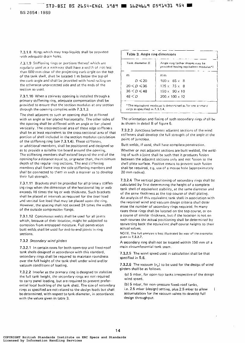
7.3.2.2 Insofar as the primary ring is designed to stabilize the full tank height, the secondary rings are not required to carry panel loading, but are required to prevent prefer- ential local buckling of the tank shell. The size of secondary rings as specified are not related to the design loads but shall be determined, with respect to tank diameter, in accordance with the values given in table 3.
Table 3. Angle ring dimensions _ _ _ ~ _
""
Tank diameter D Angle ring (other shapes m a y be provlded having equivalent modulus')
_______ __ m mm
D Q 2 0
2 0 0 x 100 x 12 4 8 < D 1 5 0 x 9 O x 10 3 6 < D < 4 8 1 2 5 x 75 x 8 20 < D G 3 6 lOOx 65 x 8
'The equivalent modulus I S determined as for t he prlmary rings as specified in 7.3.1.4.
The orientation and fixing of such secondary rings shall be as shown in detail B of figure 6.
7.3.2.3 Junctions between adjacent sections of the wind stiffeners shall develop the full strength of the angle at the point of junction.
Butt welds, if used, shall have complete penetration.
Whether or not adjacent sections are butt welded, the weld- ing of such a joint shall be such that it produces fusion between the adjacent sections only and not fusion to the shell plate surface. Positive means to prevent such fusion shall be required, e.g. use of a mouse hole (approximately 20 mm radius).
7.3.2.4 The vertical positioning o f secondary rings shall be calculated by first determining the height of a complete tank shell of equivalent stability, a t the same diameter and of the same thickness a s the top course of shell plating. An analysis of this equivalent tank shell in association with the required wind and vacuum design criteria shall deter- mine the number of secondary rings required. In many cases these rings shall be located on the top course, or on a course of similar thickness, but if the location is not on such courses the actual positioning shall be determined by converting back the equivalent shell course heights to their actual values. NOTE. The full analysis I S best illustrated by way o f the examples given in 7.3.2.7.
A secondary ring shall not be located within 150 mm of a main circumferential tank seam.
7.3.2.5 The wind speed used in calculation shall be that specified in 5.6.
7.3.2.6 The vacuum (v,) to be used for the design of wind girders shall be as follows.
(a ) 5 mbar, for open-top tanks irrespective of the design wind speed.
(b) 5 mbar, for non-pressure fixed-roof tanks, ¡.e. 2.5 mbar (design) setting, plus 2.5 mbar to allow I accumulation for the vacuum valves to develop full design throughput.
14 COPYRIGHT British Standards Institute on ERC Specs and StandardsLicensed by Information Handling ServicesCOPYRIGHT British Standards Institute on ERC Specs and StandardsLicensed by Information Handling Services
A BS 2654 : 1989
(c) 8.5 mbar, for other fixed-roof tanks. ¡.e. 6 mbar V, = 60 m/s, v, = 5 mbar, 50 K = 6.040644
for the vacuum valve to develop full design throughput. I (design) setting, plus 2.5 mbar to allow accumulation Hence
I NOTE. A lower level of total vacuum may be used in the cmpu- H, = 6.040644 = 3.254 m tation if this can be proven to be justifiable, e.9. with full-bore large free vents or low pumping r a m on non-voletile storage. Since 2Hp <HE < 3H,, two secondary rings are required.
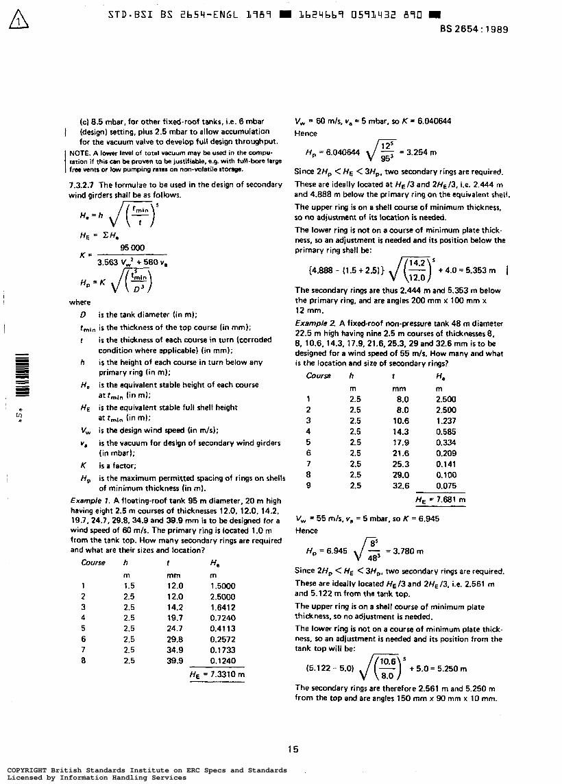
7.3.2.7 The formulae to be used in the design of secondary wind girders shall be as follows.
H, = h
H E = CH, 95 O00
K =
H, = K ,/E,) 3.563 VW2 + 580 v,,
where D i s the tank diameter (in m); rmin i s the thickness of the top course (in mm);
r i s the thickness of each course in turn (corroded condition where applicable) (in mm);
I h i s the height of each course in turn below any - primary ring (in m);
= at rmin fin m):
* at rmin (in m);
I
.I) H, is the equivalent stable height of each course
HE is the equivalent stable full shell height
V, i s the design wind speed (in m/s);
Y* i s the vacuum for design of secondary wind girders (in mbarJ;
K i s a factor;
H, i s the maximum permitted spacing of rings on shells
*. v)
of minimum thickness (in m).
Example 1. A floating-roof tank 95 m diameter, 20 m high having eight 2.5 m courses of thicknesses 12.0, 12.0, 14.2, 19.7,24.7,29.8.34.9 and 39.9 mm is to be designed for a wind speed of 60 mis. The primary ring is located 1 .O m from the tank top. How many secondary rings are required and what are their sizes and location?
Course h ? H e
m 1.5 2.5 2.5 2.5 2.5 2.5 2.5 2.5
mm m 12.0 ? .5000 12.0 2.5000 14.2 1.641 2 19.7 0.7240 24.7 0.41 13 29.8 0.2572 34.9 o. 1733 39.9 0.1 240
HE = 7.3310 m
These are ideally located at HE/^ and 2HE/3, ¡.e. 2.444 m and 4.888 m below the primary ring on the equivalent shell.
The upper ring is on a shell course of minimum thickness, so no adjustment of i ts location is needed.
The lower ring is not on a course of minimum plate thick- ness, u) an adjustment is needed and i t s position below the primary ring shall be:
(4.888 - (1.5 + 2.5)) JE)’ + 4.0 = 5.353 m I
Example 2. A fixed-roof non-pressure tank 48 m diameter 22.5 m high having nine 2.5 m courses of thicknesses 8, 8, 10.6, 14.3, 17.9, 21.6,25.3, 29and 32.6 mm is to be designed for a wind speed of 55 m/s. How many and what is the location and sire of secondary rings?
Course h t H* m 2.5 2.5 2.5 2.5 2.5 2.5 2.5 2.5 2.5
mm m 8.0 2.500 8.0 2.500
10.6 1.237 14.3 0.585 17.9 0.334 21.6 0.209 25.3 0.141 29.0 o. 1 O0 32.6 0.075
H E = 7.681 m
V, = 55 m/s, v, = 5 mbar, so K = 6.945 Hence
Since 2H, < HE < 3H,. two secondary rings are required.
These are ideally located HE I3 and 2HE /3, ¡.e. 2.561 m and 5.122 m from the tank top.
The upper ring is on a shell course of minimum plate thickness, so no adjustment is needed. The lower ring is not on a course of minimum plate thick- ness, 50 an adjustment is needed and i t s position from the tank top will be:
The secondary rings are therefore 2.561 m and 5.250 m from the top and are angles 750 mm x 90 mm x 10 mm.
15
COPYRIGHT British Standards Institute on ERC Specs and StandardsLicensed by Information Handling ServicesCOPYRIGHT British Standards Institute on ERC Specs and StandardsLicensed by Information Handling Services
Since the top stiffener cornes within 150 mm of a hori- zontal seam. it h a s to be moved. Whether it i s moved up say 21 1 mm to 2.35 m or down say 89 mm to 2.65 m from the tank top, the three portions of the tank are still stable against the design conditions as the positions resulting from moving the upper stiffener either up or down still gives a distance between the stiffeners less than H,, (= 3.78 m).
7.4 Shall pbt r arrmgamhnt The tank shall be designed to have all courses truly vertical. NOTE. It ir recomncnded that the distana between vertical joints in adjacent COUCM should not be less than ons-third of the plate Imgth. When this distance is lm than one-third of the plate length. dditional pmruliom may be McesLary to prevent undue distortion.
7.5 Shell joints
7.5.1 All vertical seams shall be bun joints and shall have full penetration and complete fusion.
7.5.2 All horizontal seams shall be butt joints and, for a distance of 150 mm at either side of each vertical seam (T-junctions), shall have f u l l penetration and complete fusion. The procedure used for welding portions of the girth seams between the T-junctions shall be that approved (see c h s e 16). NOTE. I t is m i z e d that, in practice, eontinuour full penetra- tion nuy not almmyr bo achieved tutmtn T-junctions. This need not neœsarity k ause for rejection. providd thn the k k of full penetration is intermittent, longitudinal in natun yd does not r x d appmximntly 10 X of the thicknalf of the thicker plate hid. Som diocration ir mommmded against rigorous rectification of lack of panetration. since repair welds may introduce posible hazards grsrter than the original defect.
8 Fixed-roof design
8.1 Cords Roofs shall be designed to support the loads specified in dause 5.
8.2 Typa of roof
8.2.1 One of the twu following types of roof shall be specified:
(a) the self-supporting cone or dome roof; or (b) the colurnn-supported roof.
NOTE. Column-supgorted roofs are I-~OK ncommended to be used on foundations -re significant settlement is anticipated unless special der in pmvisions are made.
8.22 The roof slope of a cone roof shall either comply with the requirements specified by the purchaser (see 322(e)(l)I or be 1 in 5. Where a domed roof is adopted, the radius of curvature shall either comply with the requirements specified by
tne pwchaser (ses 3.2(e)(2)) or be 1.5 times the diameter of the tank. NOTE. Normally the radius of curvature lies within the range 0.8 to 1.5 times the diameter of the tank.
Where a column-rupported mol ir used, a sbw of 1 in 16 is recommended.
8.3 Roof plating with supporting muetun
8.3.1 Roof-supporting structures (cone, dome or column supported) shall be designed in accordance with BS 449. The spacing of roof-plate-supporting members for cone roofs shall be such that the span between them does not exceed 2.00 m where one edge of the panel is supported by the top Curb of the tank. Where this support i s not present, the span shall not exceed 1.7 m. For dome roofs, this spacing shall be permitted to be increased as agreed between purchaser and manufacturer (sec 3.3td)).
8.3.2 Roof plates shall be continuously fillet welded to the top curb angle. For tanks exceeding 12.5 m diameter, roof plates shall not be attached to the roof-supporting structure.
8.3.3 The specified thickness of all roof plating shall be not less than 5 mm (see 4.6.1), exduding the corrosion allowance. 1 8.3.4 The steel used for construction of the roof members shall have a specified thickness of not less than 5 mm, exduding the corrosion allowance. I NOTE. This docs not apply to the d of rolled ficlel j0irtr and channels or pukiws or to struecum in which s m i a l provisiom against corrosion we made.
8.3.5 Unless othetwise specified by the purchaser (see 32(e)(3)), plates shall be lapped and continuously fillet welded on the outside with a minimum lap of 25 mm. NOTE. They should be lapped 20 that the lower edge of the u w f - most plate ir k n m t h the upper odge of the lower in order to minimize the possibility of condensate moisture entering the l a p joint. Depending on the tank contents, it may rometifms be mataw for the lm joint to be d o u b l w w l d d or m d r os 8 butt joint.
8.3.6 The joint efficiency shall be taken as 1 .O for butt welds, 0.35 for lapped joints with fillet welds on one Side only and 0.5 for lapped joints with fillet- welds on both sides. The allowable stress shall be taken as two-thirds of the yield strength. Increases in joint efficiency for a lap welded rdof plate shall be permitted by agreement between the purchaser and the manufaaurer (see 3.3(e)), provided that this can be justified by special procedure tests simulating the actua! configuration to be used on site.
8.3.7 All roof framing shall be provided with bracing in the plane of the roof surface complying with the following.
(a) Cross bracing in the plane of the roof surface shall be provided in at least two bays, ¡.e. between two pairs of adjacent rafters, on all roofs exceeding 15 m diameter. Sets of braced bays shall be spaced evenly around the tank circumference.
16 0 B S I 1997
COPYRIGHT British Standards Institute on ERC Specs and StandardsLicensed by Information Handling ServicesCOPYRIGHT British Standards Institute on ERC Specs and StandardsLicensed by Information Handling Services
., .. .
(b) Additional vertical ring bracing, on trussed roofs only, shall be provided in an approximately vertical plane between the trusses as follows:
( 1 ) roofs over 15 m up to and including 25 m diameter: one ring;
(2) roofs over 25 m diameter: two rings.
8.4 Roof plating without supporting structure (membrane roofs)
8.4.1 All membrane roofs shall be of either butt-welded or double-welded lap construction.
8.4.2 Membrane roofs shall be designed to resist buckling due to external loading and shall be checked for internal pressure.
For pressure:
r,= - (for spherical roofs) 20 sq
r, = - PR I 1osq (for conical roofs)
BS 2654: 1989
For buckling:
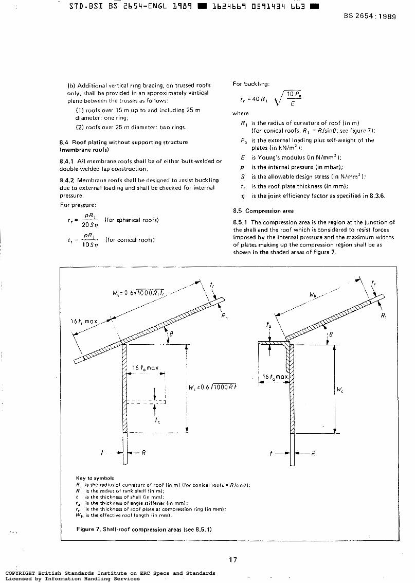
t , = 4 0 R , ,/F where
R , i s the radius of curvature of roof (in m) (for conical roofs, ßI = R/sinO; see figure 7);
P, i s the external loading plus self-weight of the plates (in kN/m2 1;
E i s Young’s modulus (in N/mm2 1; p i s the internal pressure (in mbar);
S is the allowable design stress (in N/mm2 I ; tr is the roof plate thickness (in mm);
is the joint efficiency factor as specified in 8.3.6.
8.5 Compression area
8.5.1 The compression area i s the region a t the junction of the shell and the roof which is considered to resist forces imposed by the internal pressure and the maximum widths of plates making up the compression region shall be a s shown in the shaded areas of figure 7.
Key to symbols R , i s the radius of curvature of roof (in m) (for conical roofs = /?/sino); R is the radius of tank shell (in m); r i s the thickness of shell (in mm); ta i s the thickness o f angle stiffener (in mm); r , is the thickness of roof plate at compression ring (in mm); W, is the effective roof length (in mm).
Figure 7. Shell-roof compression areas (see 8.5.1)
17 COPYRIGHT British Standards Institute on ERC Specs and StandardsLicensed by Information Handling ServicesCOPYRIGHT British Standards Institute on ERC Specs and StandardsLicensed by Information Handling Services
BS 2654 : 1989
8.5.2 The area to be provided A (in mm2 ) shall be not less than that determined by the following equation:
50p R ’ S, tan0
A = -
where
P
O
R
S C
8.5.3
i s the internal pressure, see 2.1 (less weight of roof sheets) (in mbar);
is the slope of roof meridian a t roof-shell connection (see figure 7) (in degrees);
i s the radius of tank (in m);
i s the allowable compressive stress (which, unless otherwise specified, shall be taken as 120 N/mm2) (in N/mm2 1. If a horizontal girder i s required to provide additional
cross-sectional area, this girder shall be placed as close to the junction as possible and a t a distance always less than the effective shell length for compression area W , (see figure 7).
8.5.4 The compression area shall be checked for tension ioading due to external pressure and/or vacuum condition.
8.5.5 When using a structurally-supported roof, care shall be taken to avoid excessive bending in the compression region a t the rafter connection to the shell periphery.
8.5.6 For fixed-roof tanks the minimum area defined by A in 8.5.2 or the minimum sizes of top curb angle given in table 4, whichever is the greater, shall be provided.
Tank diameter D Size of curb angle
m D G10
l O < D < 2 0 2 0 < D < 3 6 3 6 < D < 4 8 4 a < ~
mm
60 x 60 x 6 60 x 60 x 8 8 0 x 8Ox 10
1oox 1oox 12 150 x 150 x 10
8.6 Venting requirements
8.6.1 General. The precise requirements for the venting of fixed-roof tanks designed to this standard shall be either particularly specified by the purchaser (see 3.2(e)(4)) or as specified in 8.6.2 to 8.6.4 inclusive.
8.6.2 Scope of venting provided. The venting system provided shall cater for the following:
(a) normal vacuum relief;
(b) normal pressure relief;
(c) emergency pressure relief.
In the case of (c), this shall be specified in accordance with this standard unless disregarded a t the purchaser’s discre- tion (see 3.2(e)(4)). Where emergency pressure relief is required, it shall be provided by suitable vents or by the provision of a frangible roof joint (see F.3).
8.6.3 Venting capacity. The number and size of vents provided shall be based on the venting capacity obtalned from appendix F and shall be sufficient to prevent any accumulation of pressure or vacuum exceeding the values specified in 8.6A. NOTE. These valves may be fitted with coarse-mesh screens to prevent the ingress of birds. The use of fine-mesh screens as anti-flash protection is not recommended because o f the danger o f blockage, especially under winter conditions.
Conslderation should be given to the possibility of corrosion when selecting material for the wire mesh screen.
8.6.4 Accumulation of pressure and vacuum
8.6.4.1 In accordance with 7.3.2.6, the set vacuum plus the accumulation to permit the valves to achieve the required throughput shall not exceed va.
8.6.4.2 In accordance with 2.1, the set pressure plus the accumulation to permit the valves to achieve the required throughput for normal pressure relief shall not exceed the design pressure.
8.6.4.3 No specific values for emergency pressure accumu- lation are specified in this standard but the following considerations shall apply.
(a) If it is expected that the design pressure specified in 2.1 is to be exceeded by the emergency pressure accumulation, then it shall be verified that the strength of the roof-to-shell junction is adequate and whether tank anchorage is required. NOTE. This particularly applies to columnsupported cone roof tanks wi th a low roof slope and to small tanks in general.
(b) The set pressure of relieving devices for emergency conditions (if required) shall be consistent with the provisions of Fi5.2.
(c) Account shall be taken of the substantial differences between the opening and closing pressures (blowdown) that can occur between vents of different types.
NOTE .This standard does not cater for protection against over- pressure caused b y explosion within the tank, and where such protection is to be provided special consideration should be given to the design of the tank and the venting devices.
9 Floating-roof design
9.1 General
9.1.1 A floating roof, being a structure designed to float on the surface of the liquid in an open top tank and to be in complete contact withthat surface, shall comply with 9.2 to 9.15. NOTE. This clause is not applicable to the design o f floating covers installed in fixed-roof tanks in accordance with appendix E.
The requirements of this clause, unless otherwise qualified, shall apply only to the pontoon type and double-deck type of floating roofs which shall be differentiated as follows:
(a) a pontoon type roof has a continuous annular pontoon divided by bulkheads into liquid-tight pontoon compartments and has a central area covered by a Single- deck diaphragm;
18 COPYRIGHT British Standards Institute on ERC Specs and StandardsLicensed by Information Handling ServicesCOPYRIGHT British Standards Institute on ERC Specs and StandardsLicensed by Information Handling Services

(bl a doubledeck root has both an upper and a lower deck extending over the area of the liquid surf-, the lower deck in contact with the liquid surface being %parated from the upper deck by rim plata and bulk- head plates to form lquid-tight pontoon compartments.
In normal operation, the roof shall remain in the floating d i t i o n and shall only be landed on to i t s support legs for maintenance or inspection purposes. The purchaser shall specify whether the floating roof is to be designed to land as part of the normal operating procedure (see 33(f)(l)), otherwise this requirement does not apply.
9.12 The roof and accessories shall be so designed and constructed as to allow the tank to overflow and then return to a liquid level which floats the roof well below the top of the tank shell without damage to any pan of the roof, tank or appurtenances. This requirement shall apply under both servia and hydrostatic testing conditions. If a windskirt or topshell extension is used for the purpose of containing the roof seals at the highest point of travel, overflow drainage openings shall be provided to indicate the riss of the liquid level in the tank above the designed apacitv &Mt. unless the tank shell has been designed for I liquid height to the top of the shell extension.
9.13 The qncified thickness of all roof plating shall be not less than 5 mm (see 4.6.11. NOTE. A corrwion allowance is not normally specified for floating rooh but if it Is, the design should be checked in both corroded and uncotroded conditions.
9.2 hign nquinments
921 Bwymcy
9.2.1.1 Gunem/. The roof shall comply with 92.1.2.9.2.1.3 or 9.2.1 A, as appropriate.
9.212 Sqledcck pontoon roofs. The design of single- deck pontoon roofs shall comply with the following.
(a) The minimum pontoon volume of a singledeck pontoon roof shall be sufficient to keep the roof float-
on J liquid with 8 relative density not exceeding 0.7 if the ringle dedc and m y two pontoon cornp~mants
punctured and the primuv roof drain k considered as inopsntive. (b) The minimum pontoon volume of a singledeck Pontoon roof shall be sufficient to keep the roof float- ing on a liquid with a relative density not exceeding 0.7 if it carries a load of 250 mm rainfall Over the entire roof area concentrated on the centre deck and the primary roof drain is considered as inoperative. No pon- toon compartments or centre deck shall be considered to be punctured for this condition.
9.21.3 Doubkdhck roofs. The design of doubledeck roofs shall comply with the following.
(al The minimum pantoon volumc of a doubledeck roof shll be sufficient to keep the roof floating on a liquid with a relative density not exceeding 0.7 if any two Pontoon compartments are punctured and the primary roof drain i s considered inoperative. (b) The minimum pontoon volume of a doubled& roof shall be sufficient to keep the roof floating on a IhUid with a relative density not exaeding 0.7 if it
BS2654:1989
carries a 250 mm rainfall over the entire roof area in a 24 h period and the primary roof dm;.> is considered to be inoperative. NOTE.Such a requirement muy be rrtbfied by dsrio(ling the roof to csny the entire 250 mm ninfall or r l ~ i v e i y a Iwr k r d moy be urud pmvidd adequate ancrg.ncy drains are fitted which m'Il dirchmge the U~C+II minumtor dimly into the product.
When emergency drains are fitted. they shall not permit the product to flow on to the roof.
9.2.1.4 Alternative loading conditmns. By agreement between the purchaser and the manufacturer (see 33(f)), it shal l be permitted to design the roof for a fixed specific gravity. a fixed product, or a @fiad mount of rainfall deviating from the requirements of 9.2.1.2 a d 9.21.3.
9.22 Stmctural &*n. The roof shall be designed to be structurally sound under the following loading conditions.
(a) Buoyancy conditions as specified in 9.21. (b) When the roof is landed on its arpport legs a d with a superimposed load of 1.2 kWm2 (the supt?rimpofcd load is not intended to include any occumuktd rain- water).
9.3 Stability of roof under wind lord The pur- shall advim the manufacturer when tanks are to be erected in areas where wind conditions cauld give rise to fatigue loading which could reark in centre deck weld c r a c k s in m a l pontoon typa roofs, prrtiahrly for tanks over 50 m diameter, and tha desian and tvpc of rooftobeusedrhrllbe8sIpccificdbvthepurchmer (see 3.2(f)(2)). Otherwise. no account shall be taken of wind-excited fatigue Wing.
9.4 Pontoon oprningr Each compartment shall be provided with a nunway with a raimtight cover. The manway covers h l 1 be LO designcd that they will rHQlt if lifted by any gusts a d not bkw off under-the specified wind conditions. The top edge of manway necks shall be at an elevation to prevent water entering the compartments under the conditions speaficd in 9.2.
9.5 Bulkheads Either all internal bulkhead plater shall be a t least single- fillet welded along their bottom and vertical edges for liquid tightness, or when specified by the purchaser (see 32(f)(3)), the top edge of the bulkhead shall also be provided with a continuous singlc-fillet weld for liquid tightness. Bulkhead plate corners trimmed for passage of longitudinal fillet welds shall be filled by welding to obtain liquid tightness.
9.6 -.#O laddan to roofs
9.6.1 Unless othecwise specified by the purchaser (see 32cf)(4)), the floating roof shall be supplied with a ladder which automatically adjusts to any position of the
8 BSI 1997 19
COPYRIGHT British Standards Institute on ERC Specs and StandardsLicensed by Information Handling ServicesCOPYRIGHT British Standards Institute on ERC Specs and StandardsLicensed by Information Handling Services
A BS 2654 : 1989
roof in such a manner as always to provide access to the roof. The ladder shall be designed for full roof travel, regardless of normal setting of roof-leg supports. I f a rolling ladder i s furnished, it shall have full-length handrails on both sides and shall be designed for a 500 kg vertical midpoint load with the ladder in any operating position combined with the maximum wind load acting in any direction of the ladder. NOTE. Consideration should also be given to the vibration effects of wind loading and torsional rigidity of long ladders which can lead to the derailing of the ladder.
9.6.2 The ladder shall be equipped with self-levelling treads unless specified by the purchaser (see 3.2(1)(4)) that fixed rungs are to be used. NOTE l . When fixed rungs are used, ir is recommended that safety wire netting should be provided on the underside of the ladder.
NOTE 2. Attention is drawn to the need for careful selection of heights for smalldiameter tanks to permit the use of movable ladders.
9.6.3 The ladder shall run over a track, which shall be a t such a height over the deck that snow or ice will not cause derailment of the ladder.
For long and heavy ladders, special attention shall be given to the bearing width of the rails and the strength of the wheels.
9.6.4 Unless otherwise specified by the purchaser (see 3.2(f)(4)), flameshields are not required to be fitted to ladders. I f flameshields are fitted, the effect of the increased wind loading shall be considered in the design of the ladder and track.
9.7 Primary roof drains
9.7.1 Primary roof drains shall be of the hose or articulated-pipe type unless otherwise specified by the purchaser (see 3.2(f)(5)). NOTE. If specified by the purchaser, open type roof drains may be used on doubledeck roofs.
Roof drains shall be capable of operating under all specified service conditions of the roof.
9.7.2 A check valve shall be provided near the roof end of the hose, or articulated-pipe drains shall be provided on single-de& pontoon roofs, to prevent backflow of stored product on to the roof in case of leakage in the hose or the jointed pipe.
9.7.3 Provisions shall be included to prevent kinking of the hose or pinching under the deck legs.
Hose drains shall be designed to permit replacement without entering the tank.
9.7.4 The articulated joints of pipe drains shall be designed to prevent leakage. both of water into the product and vice-versa.
9.7.5 The installation of either type of drain shall include the installation of the proper shell fittings for i t s operation and, i f necessary, i t s removal.
9.7.6 The minimum size primary drain shall be equivalent in capacity to the following:
(a) one 75 mm drain for roofs up to and including 30 m in diameter;
(b) one 1 0 0 mm drain for roofs more than 30 m in diameter;
(c) one 150 mm drain for roofs more than 60 m in diameter.
9.8 Emergency drains NOTE l . Pontoon roofs. Open emergency drains should not be be installed in pontoon type roofs as the product lewl in the tank ir always higher than the rainwater level on the centre deck.
A 1 0 0 mm diameter emergency drain plug shall be located near the centre of the roof to permit the drainage of water when the roof is landed on i t s support legs. NOTE 2. To prevent backflow of the product, masures should be taken to avoid this drain plug being opened in service.
NOTE 3. Doubledeck roofs. Open type emergency drains may be installed at the centre of doubledeck roofs which will discharge rainwater directly into the product (see also 9.2.1.3(bI).
9.9 Vents
The purchaser shall specify maximum liquid filling and withdrawal rates and any special venting requirements (see 3.1(g)).
Suitable vents shall be provided to prevent overstressing of the roof deck or seal membrane. These vents or bleeder valves shall be adequate to evacuate air and gases from underneath the roof during initial filling and when the product is being withdrawn with the roof landed on i ts support legs. Operating legs for such vents shall be adjust- able to suit the various level settings of the roof-wpport legs.
9-10 supporting legs
9.10.1 Design of supporting legs. Floating roofs shall be provided with supporting legs. Legs fabricated from pipe shall be provided with a 50 mm x 25 mm notch at the bottom to provide drainage. When variable roof levels are required, the l egs shall be adjustable from the top side of the roof. The operating and cleaning position levels of the supporting legs shall be agreed between purchaser and manufacturer (see 3.3(gl).
The manufacturer shall make certain that all tank appur- tenances, such as side-entry mixers, interior piping and filling nozzles, are cleared by the roof in its lowest position.
The design of the supporting legs shall not allow product to flow on to the roof deck when the roof is loaded with the maximum specified rainfall.
9.10.2 Loading. Legs and attachments shall be designed in accordance with BS 449 to support the roof and a live load of 1.2 kN/mZ. Where posible, roof loads shall be transmitted to the legs through bulkheads or diaphragms. NOTE. These loadings do not make provision for any oil or water load or the possible effects of frequent landing of the roof (see a l so 9.1.1 1.
20 COPYRIGHT British Standards Institute on ERC Specs and StandardsLicensed by Information Handling ServicesCOPYRIGHT British Standards Institute on ERC Specs and StandardsLicensed by Information Handling Services
9.10.3 Distribution of leg loads. Measures shall be used, such as steel pads, to distribute the leg loads on the bottom of the tank. I f used, pads shall be continuously welded to the bottom plates; shim plates, also continuously welded to the bottom, shall be used when these pads coincide with lap joints in bottom plates.
9.11 Roof manholes
At least one roof manhole shall be provided for access to the tank interior and for ventilation when the tank is empty. Any additional roof manholes shall be specified by the purchaser (see 3.2(f)(6)). These manholes shall be at least 500 mm inside diameter (¡.d.) and shall have tight-gasketed and bolted covers.
9.12 Centering and anti-rotation device
Suitable devices shall be provided to maintain the roof in a centred position and to prevent i t s rotation. These devices shall be capable of resisting the lateral forces imposed on them by the roof ladder, unequal snow loads, wind loads, etc.
9.13 Seals
The space between the outer periphery of the roof and the tank shell shall be sealed by a flexible device which shall provide a reasonably close fit to the shell surfaces.
If the sealing device employs steel shoes in contact with the shell, such shoes shall be made from either stainless steel or galvanized sheet with a minimum thickness of 1.5 mm.
An adequate number of expansion joints shall be provided to aid the efficiency of the sealing,
Adequate means shall be provided to prevent an electrical charge on the floating roof causing sparking in or above the seal. In the case of seals with jointed mechanisms in the vapour space, a shunt shall be provided between the roof and shoe plate a t every such mechanism.
Any fabric or non-metallic material used as a seal or a seal component shall be durable in i t s environment and shall not discolour or contaminate the product stored. The pur- chaser shall specify the maximum aromatic content of the product which the fabric is required to resist, if greater than 40 % ( r n / r n ) (see 3.2(f)(7)). The manufacturer shall specify the maximum inward and outward movement of which the seal is capable.
9.14 Gauging device
Each roof shall be provided with a gauge hatch or gauge well with a tight cap either as specified by the purchaser (see 3.2(f)(8)) or to the manufacturer's own standard.
9.15 Operation
9.15.1 The design conditions specified in 9.2 shall not be considered as normal operating conditions but, as the ultimate conditions for flotation of the roof.
9.15.2 When primary roof drains are closed in winter, measures shall be taken to prevent the freezing of rainwater
in the lowest part of the roof drain outside the lowest shell course. NOTE. The manufacturer should supply the purchaser with an operatlng and maintenance manual which should set out the design and operattonal limitations of the floating roof and should include a t least the following points.
la) Pontoon compartments and centre decks should be checked for leaks at regular intervals; such leaks reduce the watercarrying capacity of the roof.
i b l If the primary roof draln is normally kept closed when the roof i s floating, rainwater should not b e allowed to accumulate on the roof but in any case the roof drain should be opened when water equivalent to about 75 mm rainfall has collected.
ic) If the primary roof drain i s normally kept open, frequent inspections should be made to ensure that leaking articulated joints or punctured hoses are not permitting the product to escape through the drain.
id) When the product temperature is expected to be less than O "C, the roof drain should be drained of entrapped water and then closed and the precautions outl ined in (c) observed.
( e ) The purchaser should ensure that the recommendations set out in such a manual are carefully observed by his operator.
1 O Tank anchorage
10.1 General
Tank anchorage shall be provided for fixed roof tanks if, with one of the following conditions, there may be a tendency for the shell and the bottom plate, close to the shell, to lift off its foundations.
(a) Uplift on an empty tank due to internal design pressure counteracted by the effective weight of roof and shell.
(b) Uplift due to internal design pressure in combination with wind loading counteracted by the effective weight of roof and shell, plus the effective weight of product considered by the user to be always present in the tank (see 3.1(h)).
Tank weights shall be considered after deducting any corrosion allowance.
10.2 Anchorage attachment
The anchorage shall not be attached to the bottom plate only but principally to the shell. The design shall accom- modate movements of the tank due to thermal changes and hydrostatic pressure and reduce any induced stresses in the shell to a minimum. NOTE. A typical example is shown in figure 8 but other design details are permissible.
10.3 Allowable tensile stress
For the design conditions given, the allowable tensile stress in the anchorage shall,not exceed one-half of the specified minimum yield strength or one-third of the minimum tensile strength, whichever is the lower.
21
COPYRIGHT British Standards Institute on ERC Specs and StandardsLicensed by Information Handling ServicesCOPYRIGHT British Standards Institute on ERC Specs and StandardsLicensed by Information Handling Services
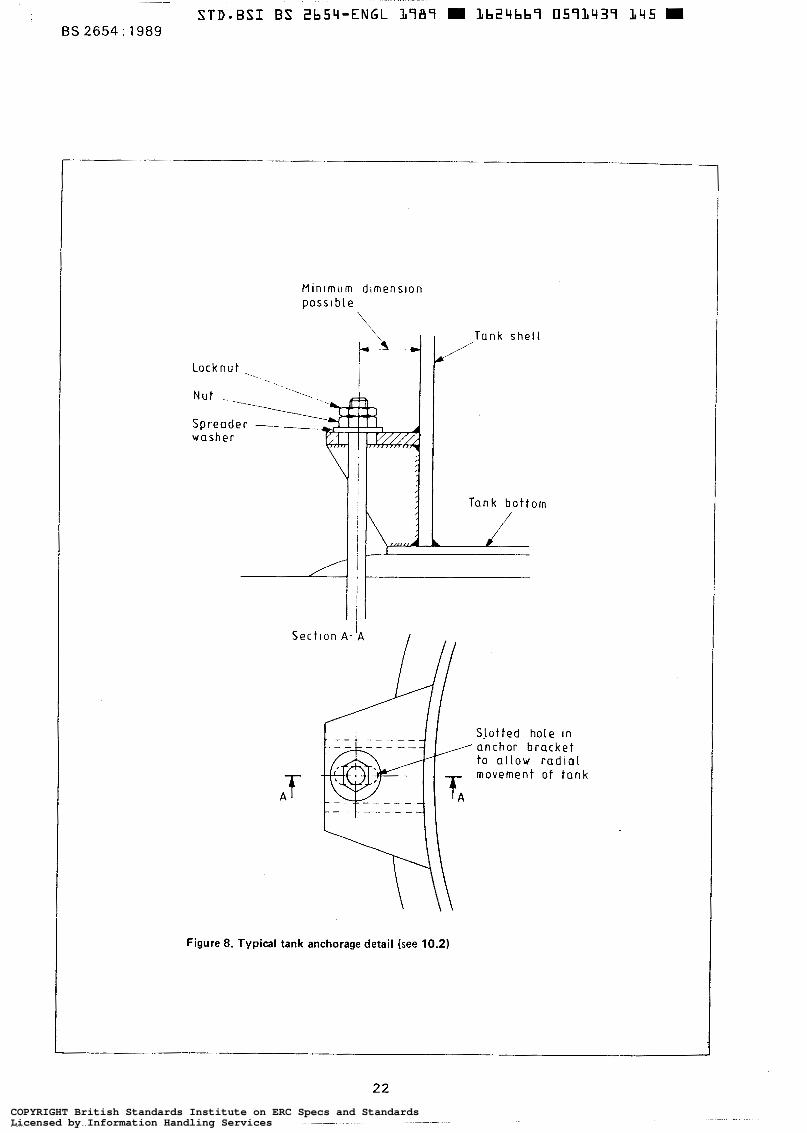
STD-BSI BS ZbSq-ENGL L787 m Lb24bb7 057L437 145 m BS 2654 : 1989
M i n i m u m d l m e n s l o n p o s s l b i e
\
S p r e a d e r -."_ w a s h e r
S e c t l o n A - I A
A f
Figure 8. Typical tank anchorage detail (see 10.2)
S l o t t e d hole I n anchor b r a c k e t t o a l l o w r a d i a l m o v e m e n t of tank
22 COPYRIGHT British Standards Institute on ERC Specs and StandardsLicensed by Information Handling ServicesCOPYRIGHT British Standards Institute on ERC Specs and StandardsLicensed by Information Handling Services
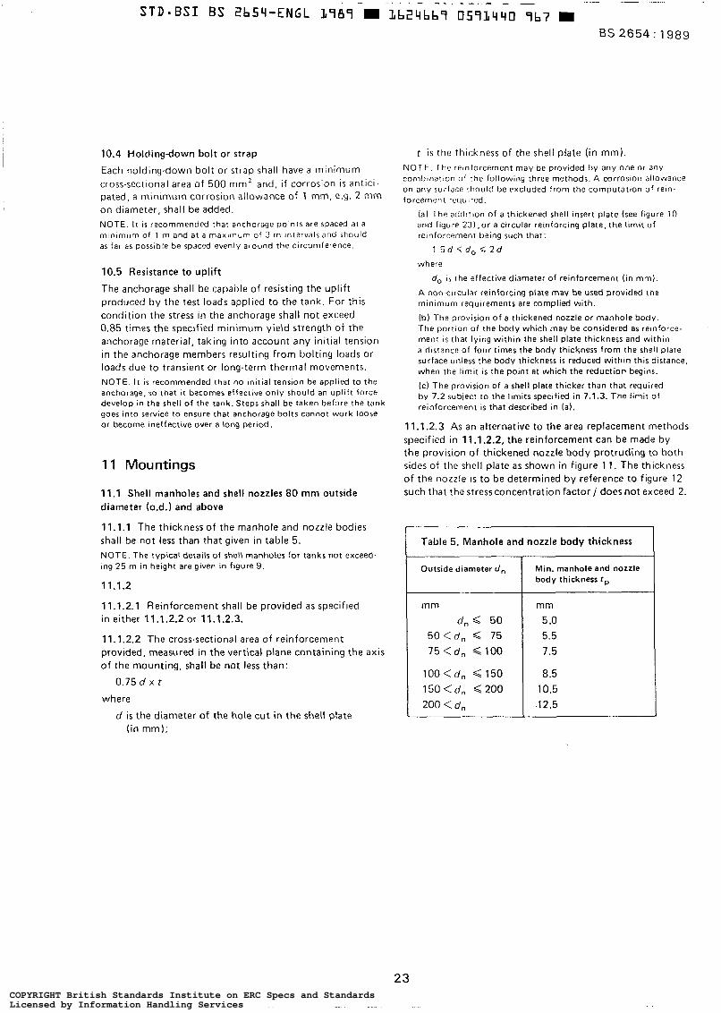
10.4 Holding-down bolt or strap
Each holding.down bolt or strap shall have a minimum cross-sectional area of 500 mm’ and, i f corrosion is antici- pated, a minimum corrosion allowance of 1 mm, e.g. 2 mm on diameter, shall be added. NOTE. It i s recommended that anchorage points are spaced at a mlnlrnurn of 1 m and at a maxlmum of 3 m intervals and should as far as posslble be spaced evenly around the circumference.
10.5 Resistance to uplift
The anchorage shall be capable of resisting the uplift produced by the tes t loads applied to the tank. For this condition the stress in the anchorage shall not exceed 0.85 times the specified minimum yield strength of the anchorage material, taking into account any initial tension in the anchorage members resulting from bolting loads or loads due to transient or long-term thermal movements. NOTE. It i s recommended that no initial tension be applied to the anchorage, so that it becomes effective only should an uplift force develop In the shell o f the tank. Steps shall be taken before the tank goes into service to ensure that anchorage bolts cannot work loose or become ineffective over a long period.
11 Mountings
11.1 Shell manholes and shell nozzles 80 mm outside diameter (o.d.1 and above
11.1.1 The thickness of the manhole and nozzle bodies shall be not less than that given in table 5. NOTE. The typical details of shell manholes for tanks not exceed- ing 25 m in height are given in figure 9.
11.12
11.1.2.1 Reinforcement shall be provided a s specified in either 11.1.2.2 or 11.1.2.3.
11.1.2.2 The cross-sectional area of reinforcement provided, measured in the vertical plane containing the axis of the mounting, shall be not less than:
0.75 d x t
where
d i s the diameter of the hole cut in the shell plate (in mm);
t i s the thickness of the shell plate (in mm). NOTE. The relnforcernent rnay be provided by any one or any combtnation of the following three methods. A corrosion allowance on any surface should b e excluded from the computatton o f rein. forcement required.
(al The addltlon o f a thickened shell insert plate ( see figure 10 and figure 23) ,or a circular reinforcing plate, the limit o f recnforcement being such that:
1 .5d do i 2 d
where
do I S t he effective diameter o f reinforcement (in mm).
A non-clrcular reinforcing plate may be used provided the minimum requirements are complied with.
(b) The provision o f a thickened nozzle or manhole body. The portion of the body which rnay be considered as relnforce- ment is that lying within the shell plate thickness and within a distance of four times the body thickness from the shel l plate surface unless the body thickness is reduced within this distance, when the l imit i s the point a t which the reduction begins.
(c) The provision of a shell plate thicker than that required by 7.2 sub~ecr to the limits specified in 7.1.3. The limit o f reinforcement is that described in (a).
11.1.2.3 As an alternative to the area replacement methods specified in 11.1 2 . 2 , the reinforcement can be made by the provision of thickened nozzle body protruding to both sides of the shell plate as shown in figure 1 1 . The thickness of the nozzle I S to be determined by reference to figure 12 such that the stress concentration factor j does not exceed 2.
r Table 5. Manhole and nozzle body thickness
Outside diameter d ,
mm dn 50
50<dn Q 75 75<dn 100
100 <dn 150 150 <d, 200 200 < d,
Min. manhole and nozzle body thickness tp
mm 5 .o 5.5 7.5
8.5 10.5
-1 2.5
23 COPYRIGHT British Standards Institute on ERC Specs and StandardsLicensed by Information Handling ServicesCOPYRIGHT British Standards Institute on ERC Specs and StandardsLicensed by Information Handling Services
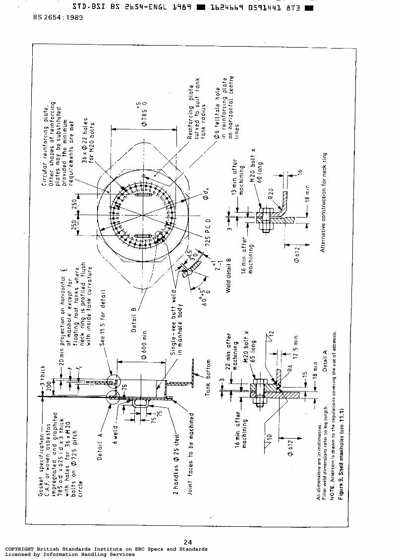
v) l"
c - E 00 r
i t
L! r"
1' c-4
c E -
24 COPYRIGHT British Standards Institute on ERC Specs and StandardsLicensed by Information Handling ServicesCOPYRIGHT British Standards Institute on ERC Specs and StandardsLicensed by Information Handling Services
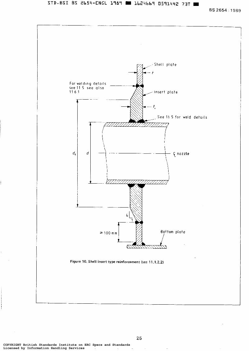
For weld lng de ta i ls see 1 1 S s e e a l s o 1 1 6 1
For weld lng de ta i ls 3 ~ I n s e r t p l a t e
A
S e e 11 S f o r
d, I
weld deta i ls
p l a t e
Figure 10. Shell insert type reinforcement (see 11.1.2.2)
25 COPYRIGHT British Standards Institute on ERC Specs and StandardsLicensed by Information Handling ServicesCOPYRIGHT British Standards Institute on ERC Specs and StandardsLicensed by Information Handling Services
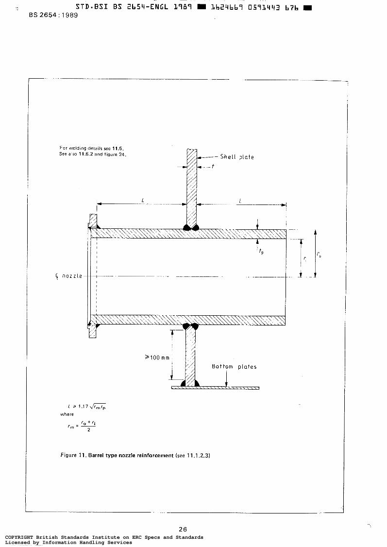
For welding details see 11.5. See also 11.6.2 and figure 24 h Shel l p la te
/ ,
nozzle 1
L Z 1 . 1 7 G
where
r, = - r. + r i
2
Figure 11. Barrel type nozzle reinforcement (see 11.1 2.3)
26 COPYRIGHT British Standards Institute on ERC Specs and StandardsLicensed by Information Handling ServicesCOPYRIGHT British Standards Institute on ERC Specs and StandardsLicensed by Information Handling Services
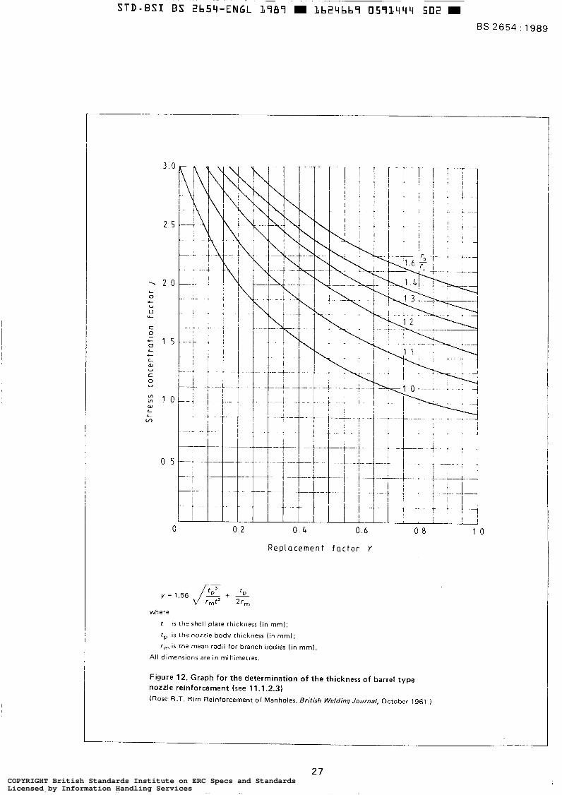
BS 2654 : 1989
L c c @J
O 0 2 O. 4 0 6 0 8 1 0
Replacement f a c t o r Y
y = 1.56 & + rmt2 Z r ,
where
f I S the shell plate thickness ( in mm);
f p is the n o z z l e body thickness ( in mm);
r m is the mean radii for branch bodies ( in mm).
All dlmensions are in millimetres.
Figure 12. Graph for the determination of the thickness of barrel type nozzle reinforcement (see 11.1.2.3) (Rose R.T. Rim Reinforcement of Manholes. Brifish Welding Journal, October 1961 .)
27 COPYRIGHT British Standards Institute on ERC Specs and StandardsLicensed by Information Handling ServicesCOPYRIGHT British Standards Institute on ERC Specs and StandardsLicensed by Information Handling Services
11.2 Shell nozzles less than 80 mm 0.d. Set-on nozzles shall not be permitted in sizes of 80 mm 0.d. and above. No additional reinforcement shall be required for nozzles less than 80 mm o.d., provided that the thick- cess of the body i s not less than that given in table 5. NOTE. Set-on nozzles (see figure 21 1 may b e used, provided that the plates are checked close to the opening to ensure that no injurious laminations are present. For thls purpose, ultrasonic or magnetic-particle crack detection is recommended.
11.3 Roof manholes and nozzles
The roof manholes shall have a minimum inside diameter of 500 mm. They shall be suitable for attachment by welding to the tank roof sheets.
The manhole covers shall be either as specified by the purchaser (see 3.2(g)) or of the multiple-bolt fixed or hinged type.
Flanged nozzles for fixed-roof tanks shall be as shown in figure 13.
11.4 Additional loads
Nozzles shall be designed to withstand the loads specified in 5.5.
11.5 Nozzle welding details NOTE 1. Typical weld details for nozzles, manholes and other openings are shown in figures 14 t o 21 and recognized weld details for connection of mountings are shown in figure 22. NOTE 2. Other forms of joint preparation are permitted by agree. ment between lhe manufacturer and the purchaser.
11.5.1 The partial penetration welds, e.g. as shown in figures 18 and 20(e) and (f), shall only be used when the shell thickness ( r ) i s not more than 12.5 mm and the allowable design stress (S) i s less than 185 N/mm2.
11.5.2 The toes of fillet welds connecting the nozzle or reinforcing plates to the shell, or the centre line of butt welds connecting insert plates to the shell, shall not be closer than 100 mm to the centre line of any other shell butt joint, the toe of the shell to bottom fillet weld, or the toe of fillet'welds of adjacent attachments. NOTE. The relnforcing plate or insert plate may be extended to the shell to bottom Junction provided the plate intersects the bottom a1 90" (see figure 23).
11.5.3 The dimensions of the welds connecting set-through nozzles to the shell are not required to be larger than twice
the wall thickness of the mounting (for examples see figures 14 to 20). When the thickness of nozzle bodies manufactured from rolled plate exceeds 20 mm, either material with specified through-thickness properties shall be used or a minimum layer of 3 mm of weld metal shall be applied to the surface of the body, prior to welding the nozzle to the shell (see figure 24).
11.5.4 Butt joints connecting insert plates to the shell plates shall have full penetration and complete fusion.
11.5.5 The leg length of fillet welds around the periphery of reinforcing plates shall equal the thickness of the rein- forcing plate or 20 mm, whichever is less.
11.6 Inspection of shell manholes and nozzles
11.6.1 The butt weld connecting insert plates to the shell plate shall be fully radiographed (see 17.3.2) in accordance with 17.4.
11.6.2 Longitudinal and circumferential butt welds in nozzles shall be 100 % visually examined to ensure complete fusion, ¡.e. in single-sided welds, the inside shall be examined to ensure adequate penetration and in double. sided welds, the back gouge shall be examined to ensure removal of the root face.
On completion, dye-penetrant crack detection shall be carried out where accessible.
11.6.3 All other welds shall be fully magnetic-particle crack detected before the hydrostatic test or, where applicable, before and after post-weld heat treatment. The weld surface shall be such as to ensure that inter- pretation of the crack detection is not impaired.
11.6.4 When the thickness of nozzle bodies manufactured from rolled plate exceeds 20 mm, that area of the body to be welded to the shell shall be ultrasonically examined to ensure freedom from laminations.
11.7 Flange drilling
Unless otherwise specified by the purchaser (see 3.2(h)), the flanges of al l mountings except shell and roof manholes shall be made and drilled in accordance with class 150 o f BS 1560 : Part 2. The orientation of mating flanges shall be checked for compatibility.
28 COPYRIGHT British Standards Institute on ERC Specs and StandardsLicensed by Information Handling ServicesCOPYRIGHT British Standards Institute on ERC Specs and StandardsLicensed by Information Handling Services
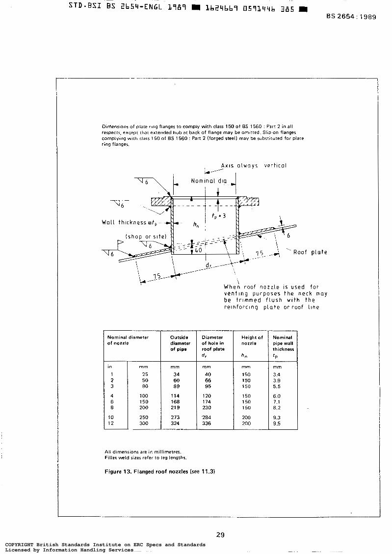
- BS 2654 : 1989
Dinlensions of plate ring flanges to comply wi th class 150 o f BS 1560 : Part 2 in all respects, except that extended hub at back of flange may be ornltted. Slip-on flanges complying with class 150 of BS 1560 : Part 2 (forged steel) may be substituted for plate ring flanges.
A X I S always vert ical
W a l l t h i c k n e s s t , ---
\ W h e n r o o f n o z z l e I S u s e d fo r v e n t i n g p u r p o s e s t h e n e c k m a y be t r i m m e d f l u s h w l t h t h e r e l n f o r c l n g p l a t e o r r o o f l l n e
Nominal diameter diameter of nozzle Outside
of pipe
in
1 2 3
4 6 8
10 12
1 O0 114 150 200 21 9
250 273 300
Diameter of hole in roof plate dr
mm
40 66 95
120 174 230
.284 336
Height o f nozzle
h"
mm
150 150 150
150 150 150
200 200
Nominal pipe wall thickness
I P
mm
3.4 3.9 5.5
6.0 7.1 8.2
9.3 9.5
All dimensions are in millimetres. Fillet weld sizes refer to leg lengths,
Figure 13. Flanged roof nozzles (see 11.3)
29 COPYRIGHT British Standards Institute on ERC Specs and StandardsLicensed by Information Handling ServicesCOPYRIGHT British Standards Institute on ERC Specs and StandardsLicensed by Information Handling Services
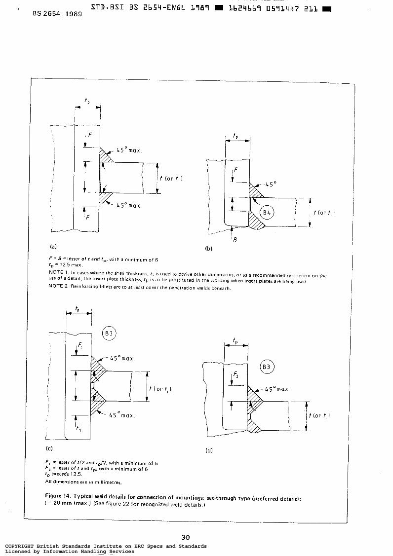
STD-BSI B S Zb59-ENGL L787 m LbZ9bb7 0573497 231 m BS 2654 : 1989
F = B = lesser of r and tp, with a minimum of 6 t , = 12.5 max.
NOTE 1 . In cases where the shell thickness, r , is used to derive other dimensions, or as a recommended restriction on the use of a detail, the insert plate thickness, f i , is to be substituted i n the wording when insert plates are being used.
NOTE 2. Reinforcing fillets are to at least cover the penetration welds beneath.
i
"-- m I - l
F , = lesser of t l 2 and t , / 2 , with a minimum of 6 F, = lesser o f t and fp, wtth a minimum of 6 tp exceeds 12.5.
All di,mensions are in millimetres.
Figure 14. Typical weld details for connection of mountings: set-through type (preferred details): t = 20 mm (max.) (See figure 22 for recognized weld details.)
COPYRIGHT British Standards Institute on ERC Specs and StandardsLicensed by Information Handling ServicesCOPYRIGHT British Standards Institute on ERC Specs and StandardsLicensed by Information Handling Services
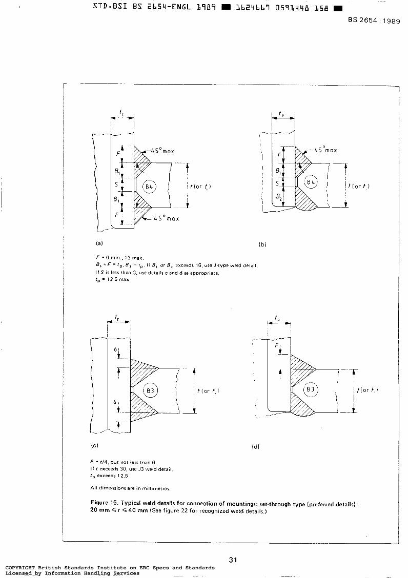
i ”I -.. \
F = 6 min., 13 max. 8, + F = f p , 8, = f p . If 8, or B, exceeds 16, use J-type weld detail
I f S i s less than 3, use details c and d as appropriate. f p = 12.5 max.
ì
i i
1.
F = t /4 , but not less than 6. I f f exceeds 30, use J3 weld detail f p exceeds 12.5
All dimensions are in millimetres.
I
Figure 15. Typical weld details for connection of mountings: set-through type (preferred details): 20 mm < t G 40 mm (See figure 22 for recognized weld details.)
31 COPYRIGHT British Standards Institute on ERC Specs and StandardsLicensed by Information Handling ServicesCOPYRIGHT British Standards Institute on ERC Specs and StandardsLicensed by Information Handling Services
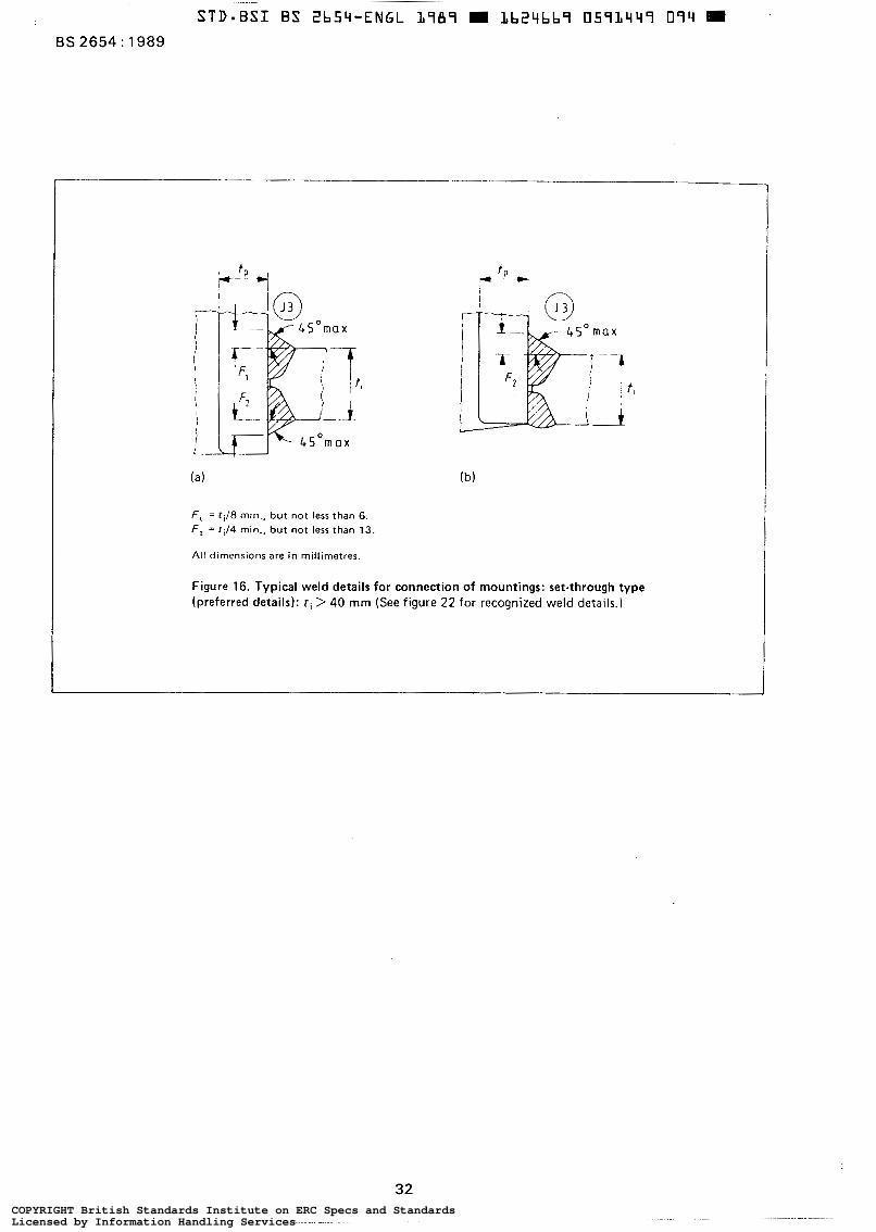
~ O r n a x
F , = ti18 min., but not less than 6. F, = ri/4 min., but not less than 13.
All dimensions are in millimetres.
Figure 16. Typical weld details for connection of mountings: set-through type (preferred details): t i > 40 mm (See figure 22 for recognized weld details.)
32 COPYRIGHT British Standards Institute on ERC Specs and StandardsLicensed by Information Handling ServicesCOPYRIGHT British Standards Institute on ERC Specs and StandardsLicensed by Information Handling Services
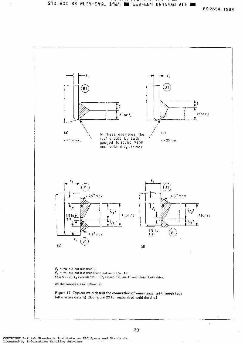
( a 1 In these examples the 1 (b)
t = 16 max. r o o t should be back gouged t o sound meta l and welded t ,=16 max
1 = 25 max.
' I
t (or t,l
F , = ~ 1 8 . but not less than 6. F , = t14. but not less than 6 and no t more than 13. t exceeds 20. Cp exceeds 12.5. If ci exceeds 50, use J1 weld detail both sides.
All dimensions are in millimetres.
Figure 17. Typical weld details for connection of mountings: set-through type (alternative details) (See figure 22 for recognized weld details.)
33 COPYRIGHT British Standards Institute on ERC Specs and StandardsLicensed by Information Handling ServicesCOPYRIGHT British Standards Institute on ERC Specs and StandardsLicensed by Information Handling Services
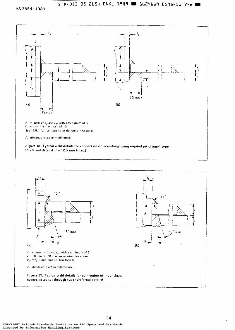
STD-BSI BS 2b54-ENGL L787 L b 2 4 b b 7 057LY5L 742 m BS 2654: 1989
u - ? t
+ 35
i 1 max F2
F, = lesser o f f p and r,, wi th a mlnimurn of 6. F , = t . with a maxlrnurn of 10. See 11.5.1 for restrictions on the use of this derail.
All dimensions are in millimetres.
Figure 18. Typical weld details for connection of mountings: compensated set-through type (preferred details): t = 12.5 mm (max.)
/
l S O m l n
F , = lesser of f p and r,. with a minimum of 6. e = 10 min. to 20 rnax. as required for access. F , = fp/3 min. but not less than 6.
All dimensions are in millimetres.
Figure 19. Typical weld details for connection of mountings: compensated set-through type (preferred details)
34 COPYRIGHT British Standards Institute on ERC Specs and StandardsLicensed by Information Handling ServicesCOPYRIGHT British Standards Institute on ERC Specs and StandardsLicensed by Information Handling Services
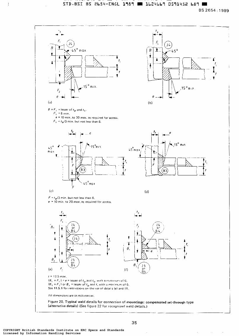
BS 2654 : 1989
(a )
B + F , = lesser o f tp and T c .
F , = 6 min.
F , = tp/3 min. but not less than 6. e = 10 min. to 20 max. as required for access
(C) (dl
F = t J 3 min. but not less than 6. e = 10 min. to 20 rnax. as required for access.
I Y e
( e ) F:
t = 12.5 max. 18, + F , I = e = lesser of rp and T c , with a minimum of 6. ( B , + F , ) or B , = lesser of tp and t. wi th a minimum of 6. See 11.5.1 for restrictions on the use o f details (e) and ( f ) .
All dtrnensions are in millimetres.
Figure 20. Typical weld details for connection of mountings: Compensated set-through type (alternative details) (See figure 22 for recognized weld details.)
35 COPYRIGHT British Standards Institute on ERC Specs and StandardsLicensed by Information Handling ServicesCOPYRIGHT British Standards Institute on ERC Specs and StandardsLicensed by Information Handling Services
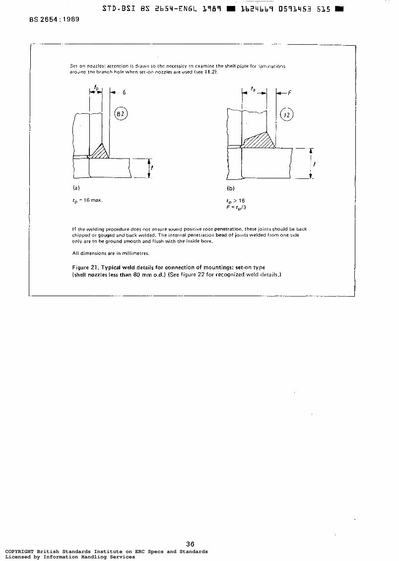
BS 2654 : 1989
Set-on nozzles: attention i s drawn t o the necessitv to examine the shell plate for laminations around the branch hole when set-on nozzles are used (see 11.2).
rp = 16 max. t p > 16 F = t , /3
I f the welding procedure does not ensure sound positive root penetration, these joints should be back chipped or gouged and back welded. The internal penetration bead of joints welded from one slde only are to be ground smooth and flush with the inside bore.
All dimensions are in millimetres.
Figure 21. Typical weld details for connection of mountings: set-on type (shell nozzles less than 80 mm 0.d.) (See figure 22 for recognized weld details.)
36 COPYRIGHT British Standards Institute on ERC Specs and StandardsLicensed by Information Handling ServicesCOPYRIGHT British Standards Institute on ERC Specs and StandardsLicensed by Information Handling Services
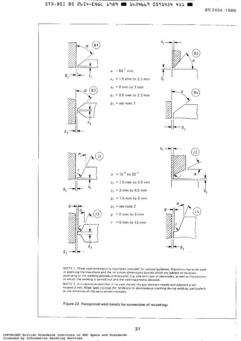
CY = 50 min.
S, = 1.5 mm to 2.5 mm
s2 = O mm to 3 mm
g , = 2.5 mm to 3.2 mm
g 2 = see note 2
s, = 1.5 mm to 2.5 mm
s2 = 3 mm to 4.5 mm
g1 = 1.5 mm to 3 mm
* gz = see note 2
g = 0 m m t o 3 m m
r = 6 mm to 13 mm
52
II-f
NOTE l . These recommendations have been included for general guidance. Discretion has to be used in applying the maximum and the minimum dimensions quoted which are subject to variation according to the welding procedure employed, e.g. size and type of electrodes, as well as the position in which the welding i s carried out apd the welding process adopted.
NOTE 2. I t is recommended that in no case should the gap between nozzle and adjacent plate exceed 3 mm. Wider gaps increase the tendency t o spontaneous cracking during welding, particularly as the thickness of the parts joined increases.
Figure 22. Recognized weld details for connect ion of mountings
37 COPYRIGHT British Standards Institute on ERC Specs and StandardsLicensed by Information Handling ServicesCOPYRIGHT British Standards Institute on ERC Specs and StandardsLicensed by Information Handling Services
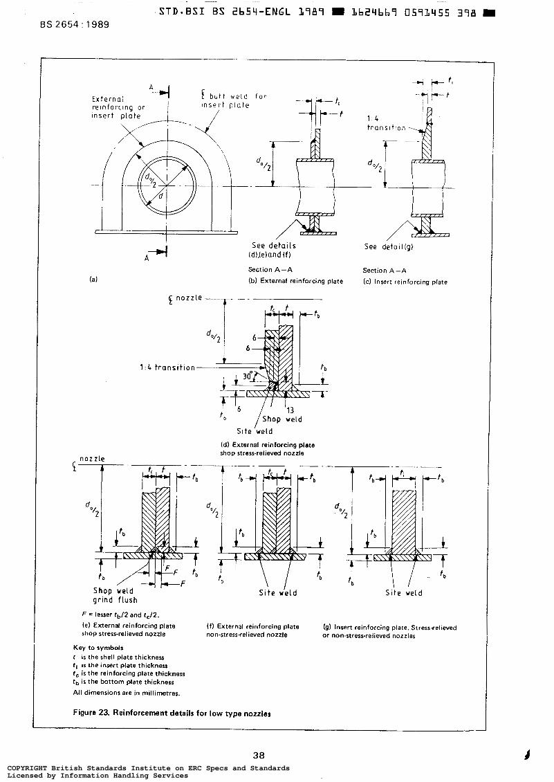
E x t e r n a l f b u t t w e l d reinforcing o r i n s e r t p l a t e
\
I I f
I
A -4 (a)
See detai ls id),[eland ( f )
Section A - A
(b) External reinforcing plate
Section A - A
(cl Insert reinforcing plate
1 : 4 t rans i t ion-
t b I l6 /ShiOp :M Slte weld
(dl External reinforcing plate shop stress-relieved nozzle
n o z z l e " "_
S i t e wéld Site w e l d grind f lush
F = lesser tbf2 and tc12.
(e) External reinforcing plate ( f ) External reinforcing plate shop stress-relieved nozzle
(9) Insert reinforcing plate. Stress+elieved non-stress-relieved nozzle or non-stress-relieved nozzles
Key to symbols r i s the shell plate thickness tl is the insert plate thickness tc i s the reinforcing plate thickness tb i s the bottom plate thickness
All dimensions are in millimetres.
Figure 23. Reinforcement details for low type nozzles
38 COPYRIGHT British Standards Institute on ERC Specs and StandardsLicensed by Information Handling ServicesCOPYRIGHT British Standards Institute on ERC Specs and StandardsLicensed by Information Handling Services
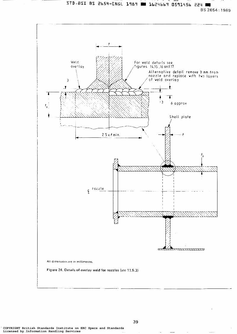
STD - BSI
Weld o v e r l a y
\
i-""" I t *
T"
e--- " n o z z l e
All dimenstons a r e In millimetres.
! Figure 24. Details of overlay weld for nozzles (see 11.5.3)
39 COPYRIGHT British Standards Institute on ERC Specs and StandardsLicensed by Information Handling ServicesCOPYRIGHT British Standards Institute on ERC Specs and StandardsLicensed by Information Handling Services

11.8 Post-weld heat treatment
11.8.1 I f mountings involving openings 300 mm or larger are welded to shell plates thicker than 20 mm, all lap or fi l let welds connecting the barrel or compensating plate to the shell and a l l butt welds incorporating plates thicker than 40 mm at the prepared edges shall be post-weld heat treated in accordance with 11.9.
11.8.2 The width of the plate containing the mounting and its reinforcement shall be a t least equal to the full width of the course and i t s length shall be not less than its width.
11.8.3 An extension pipe or flange welded to either the inside or outside of the nozzle and not forming part of the required reinforcement shall not be considered part of the assembly.
11.8.4 Subsequent welds to nozzles shall not be closer to any weld which has been post-weld heat treated than:
2.5 6 where
r i i s the inside radius of the pipe (in mm); r , is the wall thickness (in mm).
11.9 Procedure for post-weld heat treatment
11.9.1 The temperature of the furnace a t the time the assembly i s placed in it shall not exceed 400 "C.
11.9.2 The rate of heating above 400 OC (in 'C per hour) shall not exceed the following, with a maximum rate of 200 "C per hour:
5000
(t or r i ) where
t is the shell plate thickness (in mm);
t i is the bottom course plate thickness (in mm).
11.9.3 During the heating period there shall not be a greater variation in temperature thoughout the assembly being heated than 150 "C within any 5 m interval of length and when a t the holding temperature, the temperature throughout shall be within the range 580 " C to 620 "C .
11.9.4 During the heating and holding periods the furnace atmosphere shall be so controlled as to avoid excessive oxidation of the surface. There shall be no direct impinge- ment of the flame on the assembly.
11.9.5 When the assembly has attained a uniform tempera- ture as specified in 11.9.3, the temperature shall he held constant for a period in hours equal to 4 % of the thickness in millimetres of the shell plate, with a minimum of one hour.
11.9.6 The assembly shall be cooled in the furnace to 400 " C a t a rate in "C per hour not exceeding the
following, with a maximum r a t e of 250 "C per hour:
6250
( t or t i )
where t and r i are as defined in 11.9.2. NOTE. Below 400 O C , the assembly may be cooled In s1111 alr .
11.9.7 The temperatures specified shall he actual tempera- tures of any part of the assembly and shall he determined by thermocouples attached to the assembly, unless it can be demonstrated that the type of furnace used will always comply with 11.9.1 to 11.9.7.
A sufficient number of temperatures shall be recorded continuously and automatically to ensure that the whole assembly being heat-treated is within the range specified.
11.10 Stairways and gangways NOTE. For stairways on insulated tanks, see 8.5.2
11.10.1 Local regulations shall be observed and any conflict with the requirements of this standard resolved.
11.10.2 Stairways and gangways shall he of metallic construction and the minimum clear walking space shall he 600 mm. NOTE. I t is recommended that the angle of stairways to the horizontal p lane should not exceed 45 O .
11.10.3 The stairway treads shall be of the non-slip type. NOTE. The rise should normally be 200 mm with a minlmum wldth of 200 mm measured a t t he mid-length of tread. The rlse may be adjusted within t 5 mm to make treads level with landings or platforms.
11.10.4 Spiral type stairways incorporating stair treads welded directly to the shell, or by means of local pads, shall only be permissible where:
(a) the minimum specified tensile strength of the shell material does not exceed 460 N/mm* ;or (b) the minimum specified tensile strength of the shell material exceeds 460 N/mm2 and the shell thickness does not exceed 12.5 mm.
Where the minimum specified tensile strength of the shell material exceeds 460 N/mm2 and the shell thickness exceeds 12.5 mm, stairways shall be ind.ependently supported or affixed by horizontally oriented continuous welds (see 11.15).
11.10.5 Stairways and gangways shall he capable of supporting a superimposed load of 2.4 kN/m2 as well as the wind loadings specified for the design of the shell. NOTE. It is recommended that where the vertical rise of stairways i s more than 6 m, intermediate landing or landings should be provided.
11.10.6 Tank gangways which extend from one part of a tank to any part of an adjacent tank or to ground or other structure shall be so supported as to permit free relat ive movement of the structures joined by the gangway.
40 COPYRIGHT British Standards Institute on ERC Specs and StandardsLicensed by Information Handling ServicesCOPYRIGHT British Standards Institute on ERC Specs and StandardsLicensed by Information Handling Services
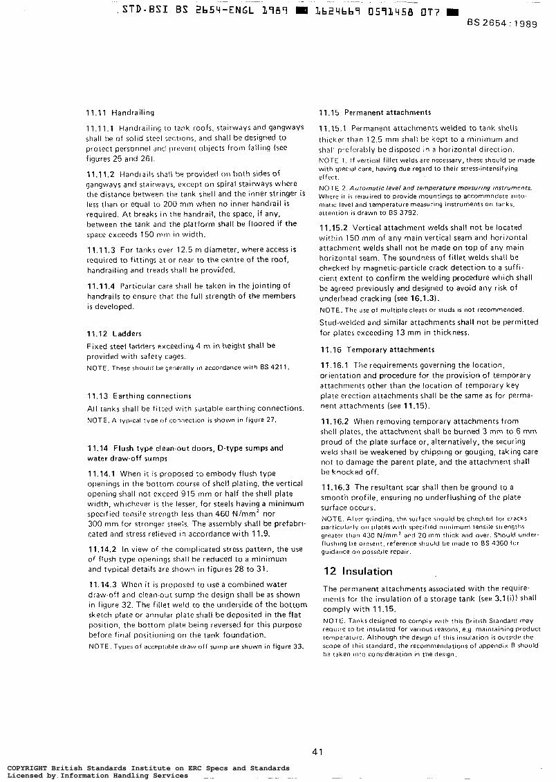
11.1 1 Handrailing
11.11.1 Handrailing to tank roofs, stairways and gangways shall be of solid steel scctions, and shall be designed to protect personnel anri prevent objects from falling (see figures 25 and 26).
11.1 1.2 Handrails shall be provided on both sides of gangways and stairways, except on spiral stairways where the distance between t h e tank shell and the inner stringer is less than or equal to 200 mm when no inner handrail is required. A t breaks in the handrail, the space, i f any, between the tank and the platform shall be floored if the space exceeds 150 mm in width.
11.1 1.3 For tanks over 12.5 m diameter, where access i s required to fittings a t or near to the centre of t h e roof, handrailing and treads shall he provided.
11.11.4 Particular care shall be taken in the jointing of handrails to ensure that the full strength of the members i s developed.
11.12 Ladders Fixed steel ladders exceeding 4 m in height shall be provided with safety cages. NOTE. These should be generally in accordance with 6s 421 1
11.13 Earthing connections
All tanks shall be fitted with suitable earthing connections. NOTE. A typacal type of connection is shown in figure 27.
11.14 Flush type clean-out doors, D-type sumps and water draw-off sumps
11.14.1 When i t is proposed to embody flush type openings in the bottom course of shell plating, the vertical opening shall not exceed 915 mm or half the shell plate width, whichever is the lesser, for steels having a minimum spectfied tensile strength less than 460 N/mmz nor 300 mm for stronger steels. The assembly shall be prefabri- cated and stress relieved in accordance with 11.9.
11.14.2 In view of the complicated st ress pattern, the use of flush type openings shall be reduced to a minimum and typical details are shown in figures 28 to 31.
11.14.3 When it is proposed to use a combined water draw-off and clean-out sump the design shall be as shown in figure 32. The fillet weld to the underside of the bottom sketch plate or annular plate shall be deposited in the flat position, the bottom plate being reversed for this purpose before final positioning on the tank foundation. NOTE. Types o f acceptable draw-off sump are shown in figure 33.
11.15 Permanent attachments
11.15.1 Permanent attachments welded to tank shells thicker than 12.5 mm shall be kept to a minimum and shall preferably be disposed in a horizontal direction NOTE 1 . If veitical f i l let welds are necessary, these should be made wi th speclal care, having due regard to their stress-intensifying effect.
NOTE 2. Automatic level and temperature measuring rostruments. Where i t i s required to provide mountings to accommodate auto- mafic level and temperature measuring instruments on tanks, attention is drawn to BS 3792.
11.15.2 Vertical attachment welds shall not be located within 150 mm of any main vertical seam and horizontal attachment welds shall not be made on top of any main horizontal seam. The soundness of fillet welds shall be checked by magnetic-particle crack detection to a suffi- cient extent to confirm the welding procedure which shall be agreed previously and designed to avoid any risk of underbead cracking (see 16.1.3). NOTE. The use of mul t ip le cleats or studs is not recommended.
Stud-welded and similar attachments shall not be permitted for plates exceeding 13 mm in thickness.
11.16 Temporary attachments
11.16.1 The requirements governing the location, orientation and procedure for the provision of temporary attachments other than the location of temporary key plate erection attachments shall be the same as for perma- nent attachments (see 11.15).
11.16.2 When removing temporary attachments from shell plates, the attachment shall be burned 3 mm to 6 mm proud of the plate surface or, alternatively, the securing weld shall be weakened by chipping or gouging, taking care not to damage the parent plate, and the attachment shall be knocked off.
11.16.3 The resultant scar shall then be ground to a smooth profile, ensuring no underflushing of the plate surface occurs. NOTE. After grinding, the surface should be checked for cracks particularly 011 plates w i t h specified minimum tensile strengths greater than 430 N/mm' and 20 mm rhick and over. Should under- flushtng h e present, reference should be made to 8 s 4360 fo r guldance on possible repair.
12 Insulation
The permanent attachments associated with the require- ments for the insulation of a storage tank (see 3. l( i )) shall comply with 11.15. NOTE. Tanks designed to comply with this British Standard may require to b e Insulated for various reasons, e.g. maintaining product temperature. Although the design of this insulation i s outslde the scope o f this standard, the recommendations of appendix B should h e taken into consideration in the design.
41
COPYRIGHT British Standards Institute on ERC Specs and StandardsLicensed by Information Handling ServicesCOPYRIGHT British Standards Institute on ERC Specs and StandardsLicensed by Information Handling Services
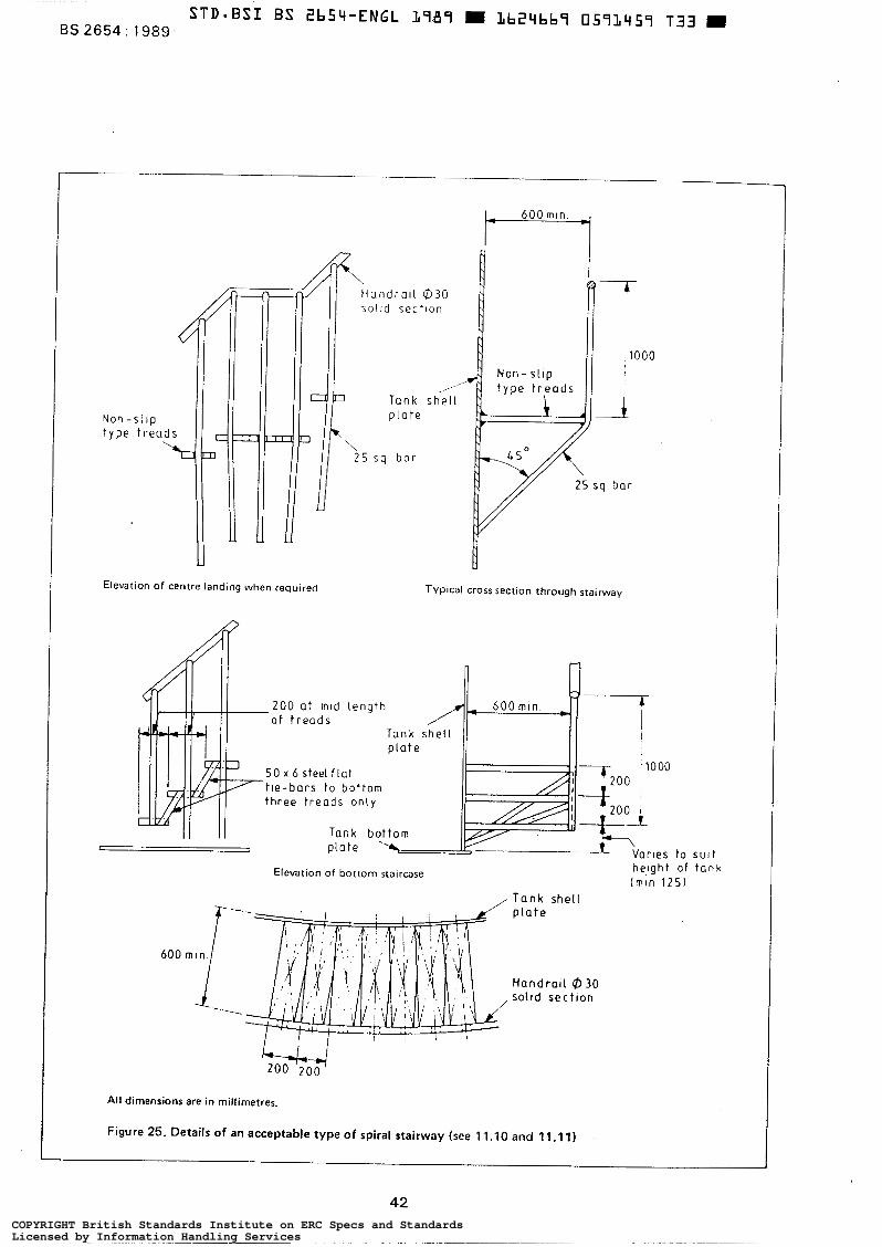
STD-BSI BS 2b54-ENGL 1787 m Lb24bb7 CI591~57 T33 BS 2654 : 1989
1 600 mln
Non - type
r,
s o l l d sec t lon
c7 Tank she l l ,
. s l i p p l a t e
,\ 2 5 s q b a r
U
Elevation of centre landing when required
I Typical cross section through stairway
200 a t m l d l eng th o f t r e a d s
5 0 r 6 s t e e l f l a t t l e -ba rs t o bo t tom three t r e a d s only
Tank b? p l a t e
Elevation of bottom staircase
, Tank shell
Varles to sult height of t ank
( m i n 1 2 5 )
1 "
600 rn ln .
-"- /
I , I
p l a t e
Handratl @ 30 solid s e c t l o n
All dimensions are in millimetres.
Figure 25. Details of an acceptable type of spiral stairway (see 11.10 and 11.11)
42 COPYRIGHT British Standards Institute on ERC Specs and StandardsLicensed by Information Handling ServicesCOPYRIGHT British Standards Institute on ERC Specs and StandardsLicensed by Information Handling Services
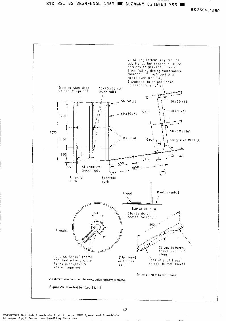
Loca l r e g u l c t l o n s n a y require
a d d l t i o n o l t o e - b o a r d s or o ther b a r r i e r s t o p r e v e n t o b j e c t s f r o m f a l l l ng du r lng ma in tenance H a n d r a l l t o r o o f c e n t r e on t a n k s Over @ 1 2 . 5 m. Standards to be Dosl t loned a d j a c e n t t o a r a f t e r
Erect lon stop shop hOx&OxSL for welded to u p r l g h t l ower ra i l s
! S - -1,
I
f - 1070
~ . 6Ox6Ox6L
5 0 x 6 M S f l a t
A l t e r n a t t v e l o w e r r o l l s
""W
4 A
I n t e r n a l E x t e r n a l c u r b curb
T r e a d
. R o o f sheets 5
: i
Treads.
I I
1
Elevat ion A - A S t a n d a r d s on
' c e n t r e h a n d r a l l
600,,. "
/' /" "' ,iR
\ / J
2 5 gap between t r e a d and roo f
Y H a n l r - l i t o r o o f c e n t r e a n d c e n t r e h a n d r a ( i on tanks over @ 1 2 S m where required
@ l b r o u n d or square Ends on ly o f t r e a d b a r
s h e e t
welded to roof sheets
Detail of treads to roof centre All dimensions are in millimetres, unless otherwise stated.
Figure 26. Handrailing (see 11.1 1)
thlck
43 COPYRIGHT British Standards Institute on ERC Specs and StandardsLicensed by Information Handling ServicesCOPYRIGHT British Standards Institute on ERC Specs and StandardsLicensed by Information Handling Services
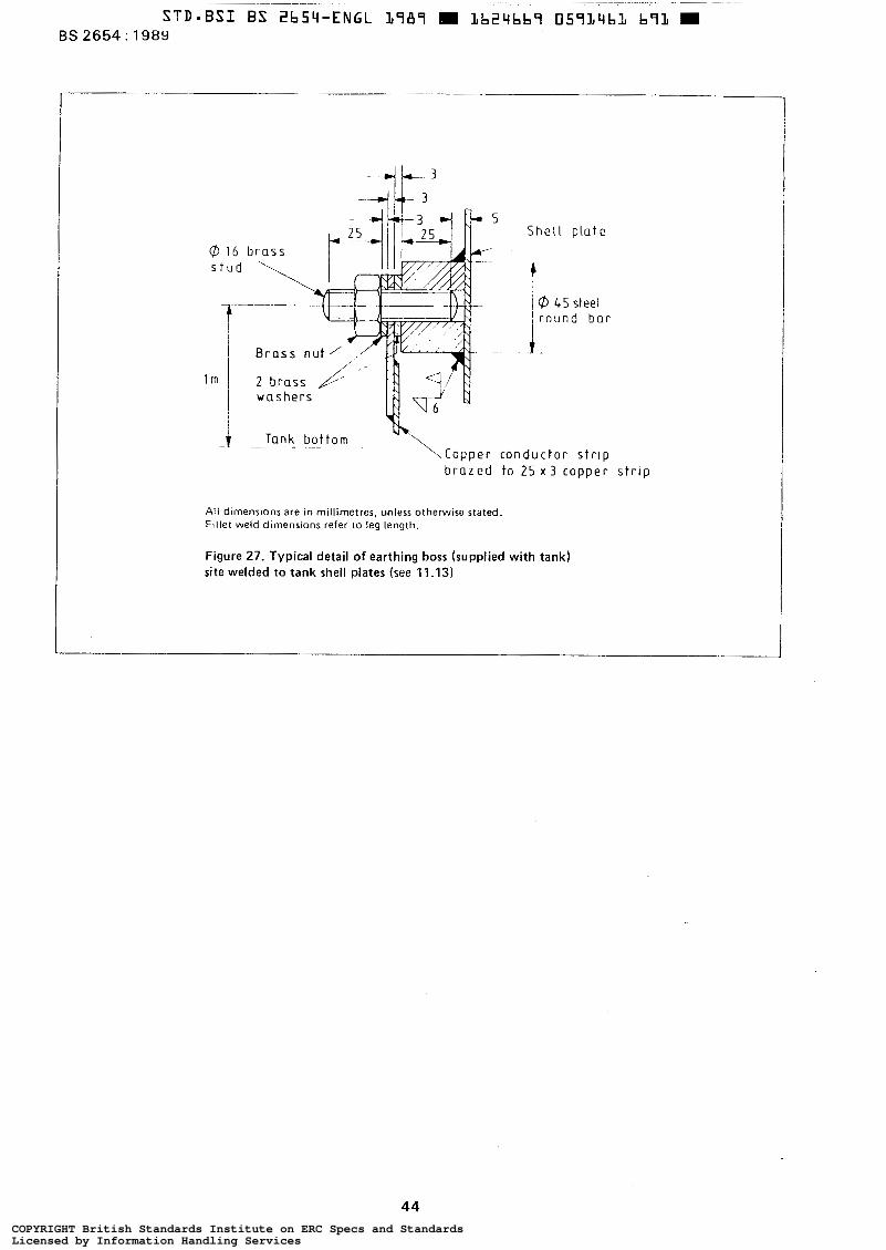
S h e l l o l a t e
c i Ø 45 steel I r o u n d b a r
- i Tank - - b o t t o m -. .
C o p p e r c o n d u c t o r s t r i p b r a z e d t o 2 5 x 3 c o p p e r s t r i p
All dimensions are in millimetres, unless otherwise stated. Ftllet weld dlmensions refer to leg length.
Figure 27. Typical detail of earthing boss (supplied with tank) site welded to tank shell plates (see 11 .I31
44 COPYRIGHT British Standards Institute on ERC Specs and StandardsLicensed by Information Handling ServicesCOPYRIGHT British Standards Institute on ERC Specs and StandardsLicensed by Information Handling Services
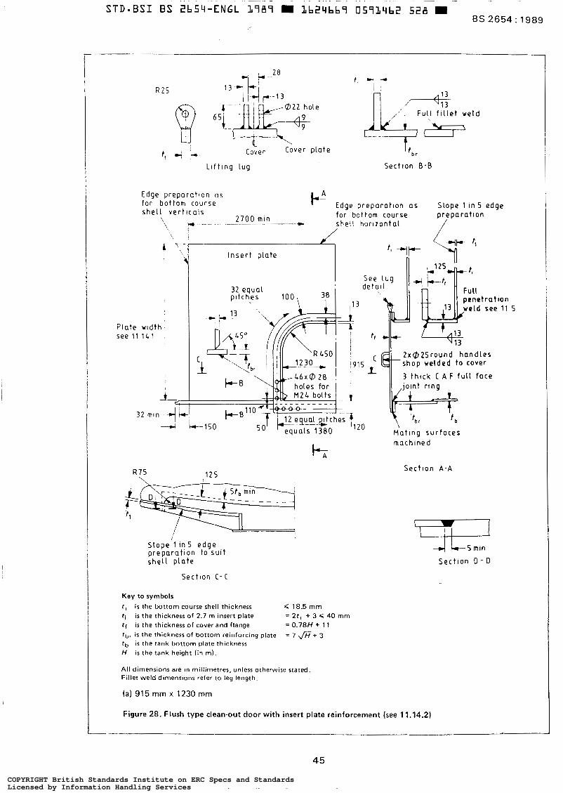
Edge prepara t lon as for bot tom course )-" Edge p repara t ton as Slope 1 In S edge s h e l l v e r t i c a l s
\ for bot tom course p r e p a r a t l o n she l l ho r l ron ta l ""
I n s e r t p l a t e tl "ip- Ifl c "., c-
Plate width see 11 1 L 1
I
I 1 t + !
L
3 2 equal
Z x Ø Z S r o u n d h a n d l e s shop welded t o cover
3 t h l c k C A F f u l l f a c e
h 12 S
S l o p e ' l I n S edge p r e p a r a t i o n t o su i t s h e l l p l a t e
Sect lon C - C
Key to symbols
C , i s the bottom course shell thickness 18.5 mm f i i s the thickness of 2.7 m insert plate = 2 t , + 3 4 40 m m f f i s the thickness of cover and flange = 0.78H + 11 rb, is the thickness of bottom reinforcing plate = 7 f i + 3 tb i s the tank bottom plate thickness H i s the tank height (in m).
All dimensions are in millimetres, unless otherwise stated Fillet weld dimensions refer to leg length.
(a) 915 mm X 1230 mm
j o l n t r l n g 4 A t 3
''br 'b
M a t i n g s u r f a c e s mach lned
Sec t lon A - A
Figure 28. Flush type clean-out door with insert plate reinforcement (see 11.14.2)
45
COPYRIGHT British Standards Institute on ERC Specs and StandardsLicensed by Information Handling ServicesCOPYRIGHT British Standards Institute on ERC Specs and StandardsLicensed by Information Handling Services
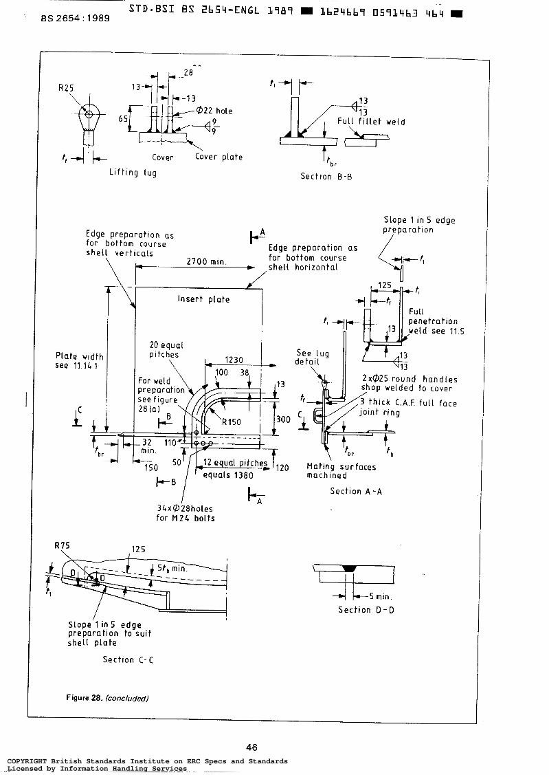
1 R 2 5
~ L i f t i n g l u g Sect lon 8 - 8
Slope 1 in 5 edge
Edge preparat ion as for bottom course s h e l l v e r t i c a l s
P p r e p a r a t i o n
Edge preparat ion as for bottom course s h e l l h o r i z o n t a l
welded t o cover
20 M a t i n g s u r f a c e s m a c h i n e d
Sect ion A - A
for M 2 4 bol ts
4 L - ~ m i n .
S e c t i o n D - D
S l o p e ' l in 5 e d g e p r e p a r a t i o n t o s u i t s h e l l p l a t e
~ Sect ion C- C
Figure 28. (concluded)
46 COPYRIGHT British Standards Institute on ERC Specs and StandardsLicensed by Information Handling ServicesCOPYRIGHT British Standards Institute on ERC Specs and StandardsLicensed by Information Handling Services
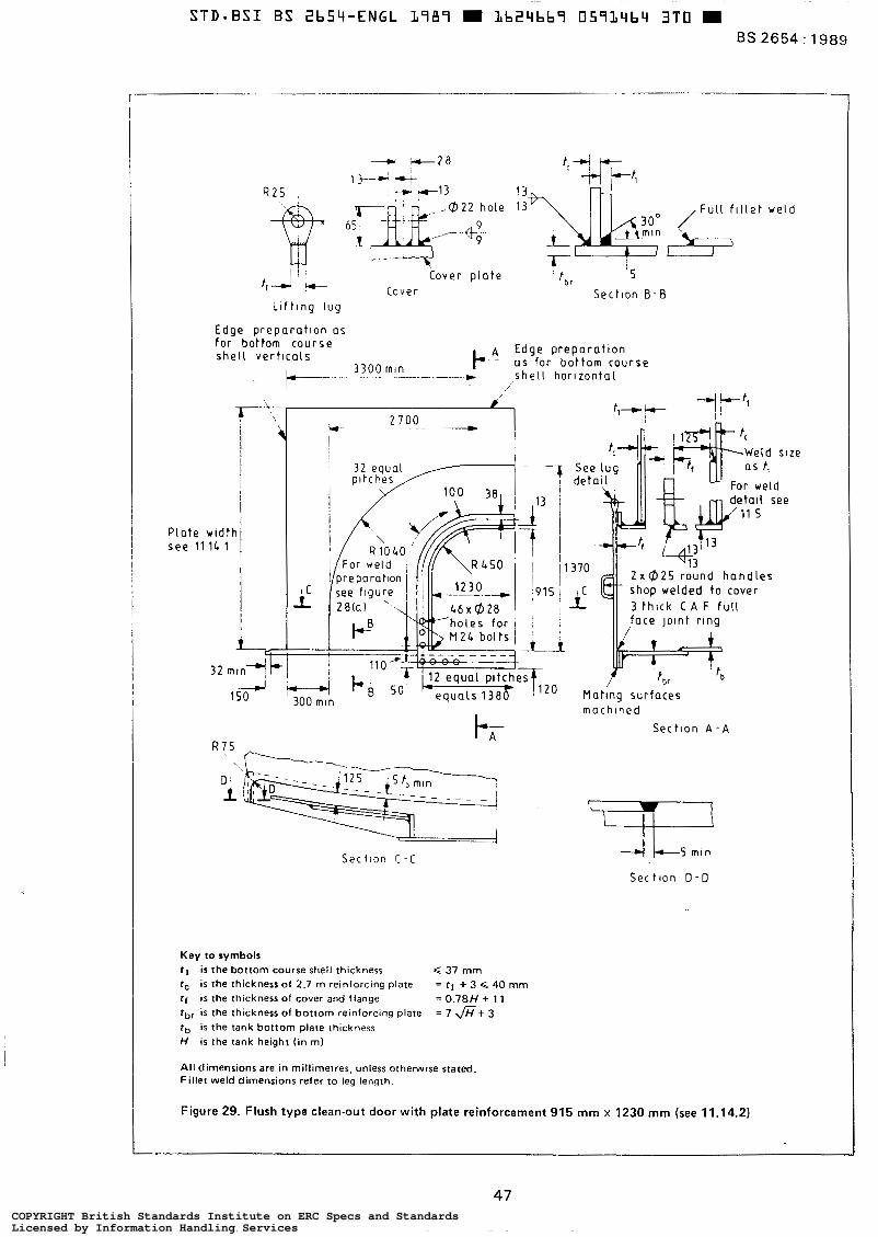
BS 2654 : 1989
R 2 5 ,
_."+
[Fu l l f l l l e t w e l d
I ! Cover p l a t e
! t , r ' S
Cover Sect lon 6-13 L l f t l n g l ug
Edge p repara t lon as for bottom course s h e l l verticals Edge p repara t i on
t- 3300 mln F' as for bot tom course . - * s h e l l h o r l z o n t a l r
Pla te w id th see 11 1L 1 i
150 4
W"". 2700 __c - "_
!
R 7 5
Sec t l on C - c
See l u g d e t a l l For weld
de ta l l see 11 S
370 2 x 0 2 5 r o u n d h a n d l e s
i 3 t h ~ c k C A F f u l l shop welded to cover
II ,face Jornt rrng
Mat ing sur faces mach ined
Sect lon A - A
S e c t l o n D - D
Key to symbols t l i s the bottom course shell thickness r, is the thickness of 2.7 m reinforcing plate = r, + 3 Q 40 mm tf i s the thickness of cover and flange = 0.78H + 1 1 tbr is the thickness of bottom reinforctng plate = 7 f i t 3 tb is the tank bottom plate thickness H i s the tank height ( i n m)
All dimensions are in millimetres, unless otherwise stated. Fillet weld dimensions refer to leg length.
37 mm
Figure 29. Flush type clean-out door with plate reinforcement 915 mm x 1230 mm (see 11.14.2)
47 COPYRIGHT British Standards Institute on ERC Specs and StandardsLicensed by Information Handling ServicesCOPYRIGHT British Standards Institute on ERC Specs and StandardsLicensed by Information Handling Services
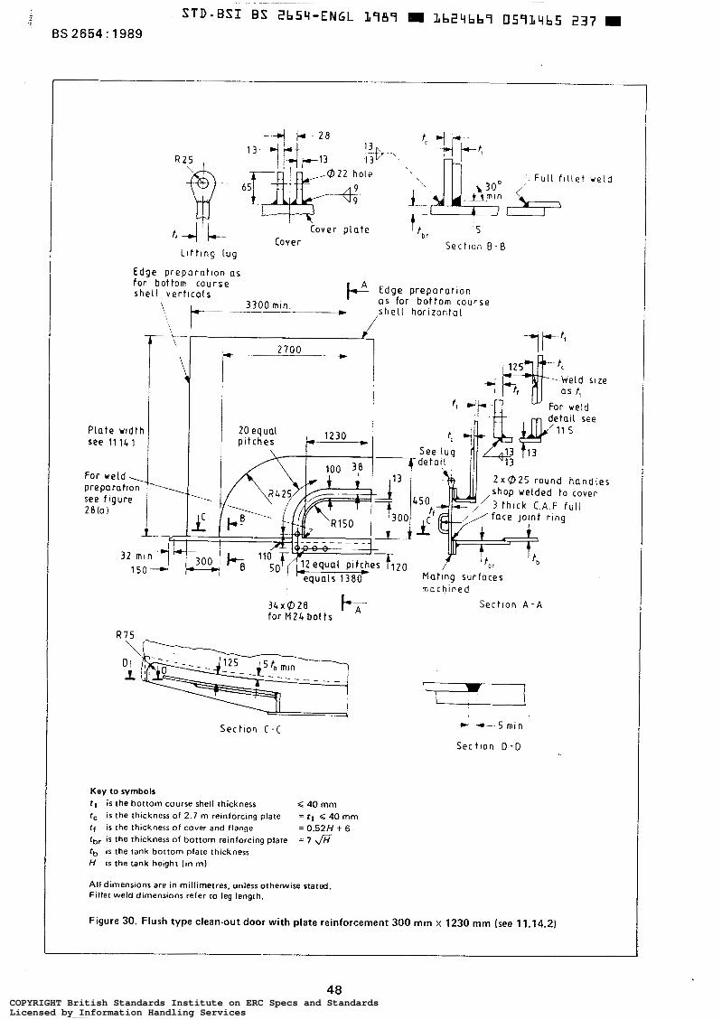
Pla te w id th see 11. lL 1
For weld, preparat ion see frgure 28(a)
I -
Edge p repara t ion as f o r bottom course s h e l l v e r t l c a l s Edge p repara t l on F as fo r bot tom course
s h e l l h o r i z o n t a l
-
R 7 5
-2-
f, t I 300
-i
2700 *
2 x 0 2 5 r o u n d h a n d l e s shop welded to cover
Mat ing sur faces n a c h i n e d
3 4 x 6 2 8 k Sect ion A - A for M 2 4 b o l t s
- H
Sec t l on C -C
Key to symbols tl i s the bottom course shell thickness 4 40 mm r, i s the thickness o f 2.7 m reinforcing plate = r, 40 mm f f i s the thickness o f cover and flange = 0.52H + 6 tbr i s the thickness of bottom reinforcing plate = 7 fi tb i s the tank bottom plate thickness H i s the tank height (in m)
All dimensions are in millimetres, unless othenwise stated. Fillet weld dimensions refer to leg length.
7 L I
* +"S min
Sec t l o n D - D
11.14.2) Figure 30. Flush type clean-out door with plate reinforcement 300 mm x 1230 mm (see
4% COPYRIGHT British Standards Institute on ERC Specs and StandardsLicensed by Information Handling ServicesCOPYRIGHT British Standards Institute on ERC Specs and StandardsLicensed by Information Handling Services
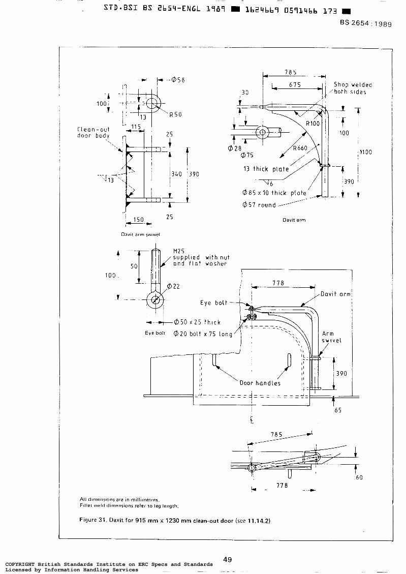
Davit arm swivel
I
1 0 0 ,
J ~ ~-
($85 x 10 thlck p l a t e
Davit arm
s u p p l l e d wl th n u t a n d f l a t washer 50 r
All dimensions are in millimetres. Fil let weld dimensions refer to leg length.
i J I
6 5
O
COPYRIGHT British Standards Institute on ERC Specs and StandardsLicensed by Information Handling ServicesCOPYRIGHT British Standards Institute on ERC Specs and StandardsLicensed by Information Handling Services
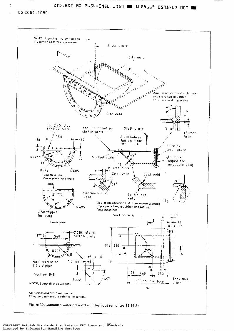
NOTE. A gratlng may be f l tted to ~.
the sump a5 a safety precaution Shel l p i a t e
S i t e weld
nular or bot tom sketch plate be reversed to permlt wnhand welding at s ~ t e
18 x 02 S holes f o r M 2 2 bolts
End elevation Cover plate not shown
Gasket specification C.A.F. or woven asbestos impregnated and graphited and mating faces machined
f o r plug S e c t l o n A - A
Cover plate
6iO o d plpe
S e c t l o n B-B Tank shei ,
NOTE. Sump all shop welded.
Plan
All dimensions are in millimetres. Flllet weld dimensions refer t o leg length.
Figure 32. Combined water draw-off and clean-out sump (see 11.14.3)
50 COPYRIGHT British Standards Institute on ERC Specs and StandardsLicensed by Information Handling ServicesCOPYRIGHT British Standards Institute on ERC Specs and StandardsLicensed by Information Handling Services
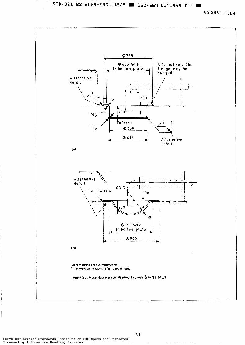
BS 2654 : 1989
t*-l A l t e r n a t i v e l y t h e
U Al ternat ive de ta¡ l
All dimensions are in millimetres. Fillet weld dimensions refer to leg length.
Figure 33. Acceptable water draw-off sumps (see 11.14.3)
51 COPYRIGHT British Standards Institute on ERC Specs and StandardsLicensed by Information Handling ServicesCOPYRIGHT British Standards Institute on ERC Specs and StandardsLicensed by Information Handling Services
~ ~~
STD=BSI BS 265Y-ENGL L787 W L b Z Y b b 7 05714b9 782 m BS 2654: 1989
13 Shop fabrication
13.1 Workmanship The workmanship and finish shall be subjected to close inspection by the manufacturer to ensure that they comply with al l requirements of this standard. NOTE. This is required whether o r not the purchaser waives any part o f his inspection.
13.2 Hard stamping
Hard stamping shall only be permitted for the purpose of plate identification and in any case shall be kept to a minimum.
13.3 Plate edge preparation
13.3.1 All edges of a l l plates except bottom and roof plates, shall be prepared by shearing, machining, chipping or cutting with a machine-operated cutting torch. For butt- welded joints, shearing shall be limited to 10 mm thickness of plates.
13.3.2 For bottom and roof plates from a steel reversing mill, further edge preparation shall not be required.
The edges of the products of a s tee l strip mill shall be trimmed in accordance with 13.3.1 to achieve a square edge or double-run fillet welds shall be adopted to ensure adequate root penetration. NOTE. This reaulrement is necessary since the longitudinal edge produced by the mill may not be sufficiently square to unsure a sound fillet weld with full throat thickness.
13.3.3 When manual oxygen cutting is used for trimming outside circumferential edges of roof and bottom sketch plates, such oxygen-cut edges shall be properly cleaned for welding, free from oxide and cutting scale. NOTE. These should be reasonably smooth at the welding edges, although this would not normally require grinding i f a good quality of workmanship i s achieved.
13.3.4 All shell plates shall be profiled to a tolerance of f. 2.0 mm in length and width. In addition, to ensure that plates are truly rectangular, the diagonals, measured across the rectangle formed by scribing lines 50 mm from each edge, shall not differ by more than 3 mm.
For lap welded roof and bottom plates, normal mill tolerances shall be acceptable. 1 13.4 Rolling and pressing
When required, to comply with the dimensional require- ments of this standard, shell plates shall have ends preset and b e rolled to correct curvature. NOTE. If plates are not rolled, the manufacturer should inform the purchaser.
13.5 Bolt holes
All bolt holes shall be punched or drilled to template so that similar parts are interchangeable. Badly matched holes shall not be corrected by drifting.
13.6 Surface preparation and painting
13.6.1 Unless otherwise specified by the purchaser (see 3.2(¡)) , painting shall be as specified In 13.6.2.
13.6.2 All roof structural members, stairways and hand- railings manufactured from mild steel shall be thoroughly cleaned and freed from rust and scale by pickling, or blast cleaning, and painted immediately a f t e r cleanlng with a primer coat of paint.
13.6.3 The method and extent of surface cleaning and painting for al l other materials shall be specified by the purchaser (see 3.2(i) and A.3.4).
13.6.4 Special consideration shall be given to the need to protect welding margins, machined surfaces, nuts and bolts, etc. from corrosion during shipment and construction.
13.7 Erection marks (domestic market)
13.7.1 Tanks erected by manufacturer. All plates and structural members shall be marked in accordance with the manufacturer's normal practice, unless specified otherwise by the purchaser (see 3.2(j)).
13.7.2 Tanks erected by others. All plates and structural members shall be marked in accordance with a marking diagram to be supplied by the manufacturer which shall also bear such other marks as may be required to facil i tate erection. Erection marks shall be painted clearly on plates and structural members in symbols a t leas t 50 mm high, where practicable, and in the case of curved plates, such marks shall be on the inside surface.
13.8 Erection marks (export market)
All plates and structural members shall be marked in accordance with a marking diagram to be supplied by the manufacturer which shall also bear such other marks as may be required to facilitate erection overseas.
Erection marks shall be painted clearly on plates and structural membeis in white paint and shall be a t least 50 mm high. In addition, it may be necessary for them to be hard stamped (see 13.2) in symbols not less than 13 mm high, which in the case of plates shall .be in the corner approximately 150 mm from either edge. For curved plates, such marks shall be on the inside surface.
13.9 Packaging
13.9.1 Structural materials and tank plates. All materials to be erected either by the manufacturers or by others shall be bundled and packaged in accordance with the usual requirements for the mode of transport, taking into account the handling facilities available in transit, and every care shall be taken to guard against damage or loss.
13.9.2 Mountings and fittings. Where flange gaskets are packed separately, they shall be adequately protected against damage in transit. NOTE, Roof and shell manholes, nozzles, bottom sumps. clean-outs. etc. may be sent loose with covers bolted on.
COPYRIGHT British Standards Institute on ERC Specs and StandardsLicensed by Information Handling ServicesCOPYRIGHT British Standards Institute on ERC Specs and StandardsLicensed by Information Handling Services
13.9.3 Welding electrodes. Welding electrodes shall be supplied in containers which give adequate protection against damage and moisture in transit and in storage on site. The type of packing to be employed shall be specified by the electrode manufacturer. NOTE. ldentification. Each case, bundle or package wherever possible should be provided with suitable identification marks giving weight or other desired particulars.
14 Site erection
14.1 General
Unless otherwise specified by the purchaser (see 3.2(k)), the responsibility for supplying welding electrodes and/or key plating equipment lies with the manufacturer. The responsibility for the supply of site erection equipment, labour, false work, etc. lies with the erection contractor.
14.2 Workmanship The erector shall carry out an inspection of the workman- ship and finish to ensure that they comply with all the requirements of this standard. NOTE. This will be completed irrespective of whether the purchaser waives any part of his own inspection.
14.3 Tank foundation construction
Unless he makes alternative arrangements (see 3.2(1)), the foundation for receiving the tank bottom shall be provided by the purchaser. NOTE l . I t i s recommended that its construction be in accordance w i th appendix A. Al l reasonable care should be taken to prevent damage to the foundation during erection.
The top of the foundation levels shall be checked a t a handover stage to the tank erection contractor and the difference in level of the surface of the tank foundation between any two points 10 m apart around the periphery of the tank shall not be greater than k 6 mm and the envelope of peripheral surface levels shall l ie within 12 mm above to 12 mm below the design levels, NOTE 2 . Closer tolerances in the tank foundation peripheral levels may be necessary in thecase of floating.roof tanks. Uneven founda- tion conditions and settlement can result in the shell assuming an oval shape at the top, causing the floating roof to stick.
14.4 Rectification of damage to materials
Any damage to material shall be corrected to the satisfac- tion of the purchaser prior to erection (see 3.4(a)).
14.5 Erection of plates
14.5.1 The method proposed to hold the plates in position for welding shall be approved by the purchaser, unless such approval has already been given in writing by the purchaser (see 3.3(h)).
14.5.2 The course of shell plates to be erected first shall be held in position by metal clamps or other devices attached to the bottom plates whilst it is plumbed and checked for circularity and before it is tack welded or welded. In setting
out this course, care shall be taken to ensure that due allowance i s made for the contraction of the vertical joints during welding.
14.5.3 On a l l lap joints, the plates shall be held in close contact during the welding operation. The surfaces where the weld metal is to be applied shall be thoroughly cleaned before assembly.
14.5.4 Lugs attached by welding to the tank, and needed only for purposes of erection, shall comply with 11.16.
14.6 Shell tolerances
14.6.1 The shell shall comply with 14.6.2 to 14.6.6, which wil l ensure that the tank shell is being erected in a satis- *
factory manner in order that the completed tank will have an acceptable appearance and assist in maintaining the satisfactory function of a floating roof, if fitted.
14.6.2 The tolerances specified in 14.6.3 to 14.6.6 shall only apply to the tank during erection.
The location and number of tolerance measurements on the shell taken during erection and on completion shall be by agreement between the purchaser and the manufacturer (see 3.3(¡11.
14.6.3 The internal radius measured horizontally from the centre of the tank a t floor level shall not vary from the nominal internal radius by more than the following:
(a) tanks 12.5 m diameter: ? 13 mm;
(b) tanks > 12.5 m 45 m diameter: * 19 mm:
(c) tanks > 45 m diameter: k 25 mm.
14.6.4 The overall height of the shell shall not be out of vertical by more than 1 in 200. NOTE. This standard of verticality should apply to each individual course which should be erected within the same tolerance.
14.6.5 Local departures from the design form shall be gradual and sharp changes in form shall not be permitted. NOTE. At horizontal and vertical ¡oints the shell profile should not deviate f rom i t s design form by more than the following measured over a gauge length of 1 m:
(al plates < 12.5 mm th ick : 10 mm;
(bl plates > 12.5 mm < 25 mm th ick : 8 mm;
(c) plates > 25 mm thick: 6 mm.
14.6.6 Plates to be joined by butt welding shall be matched accurately and retained in position during the welding operation. Misalignment of the plates shall not exceed the following.
(a) In completed vertical joints: 10 % of the plate thickness, or 1.5 mm for plates 19 mm thick and under, and 3 mm for plates over 19 mm thick, whichever is the larger.
(b) In completed horizontal joints: 20 %of the upper plate thickness, or 1.5 mm for plates 8 mm thick and under, and 3 mm for plates over 8 mm thick, whichever i s the smaller.
NOTE. The tank shell should be checked forcircularity, dimensions and level before the roof members are positioned or the primary wind girder i s erected.
53 COPYRIGHT British Standards Institute on ERC Specs and StandardsLicensed by Information Handling ServicesCOPYRIGHT British Standards Institute on ERC Specs and StandardsLicensed by Information Handling Services
BS 2654 : 1989
14.7 Floating-roof tolerances
The difference in the gap between the shell and the peri- phery of the roof on completion of erection of the roof shall not exceed i- i 3 mm from the nominal gap. NOTE. A t any elevation of the roof other than that at which it was erected, this difference in gap should not exceed t 50 mm or such other value as may be agreed between the purchaser and the manufacturer for a partlcular seal design.
14.8 Manual oxygen cutting
14.8.1 If manual oxygen cutting is used for trimming outside circumferential edges of roof and bottom sketch plates and for trimming corners of bottom plates where two lapped joints intersect, such oxygen-cut edges shall be properly cleaned for welding and free from oxide and cutting scale. NOTE. These should be reasonably smooth at the welding edges although this would not normally require grinding if a good quality of workmanship is achieved. I t i s particularly important for the sketch to annularplate connection to be properly prepared and fitted for welding.
14.8.2 When openings for fittings fixed on site are manually oxygen cut, then radius arms, straight edges and nozzle guides shall be used. The cut edge shall be cleaned and trimmed by chipping or grinding where necessary to maintain the correct weld preparation.
14.9 Protection of shell during erection
The erection contractors shall employ suitable methods for the protection of the shell during erection which have been agreed with the purchaser (see 3.3(j)). When required by the purchaser, full details of these methods shall be made available for his approval. The factors to be taken into account when determining the suitability of the proposed method of protection shall be:
(a) tank size;
(b) construction method;
(c) location and degree of exposure to wind loads;
(d) number and type of key plate equipment;
(e) availability of reliable meteorological data during al l periods of erection.
NOTE. The use of steel wire guys or cables may not necessarily be adequate and consideration should be given to the use of temporary wind girders.
14.10 Erection of fixed roof
The-temporary support for the erection of roof framing shall remain in position until the completion of the main
14.12 Final surface finish
The final surface preparation and painting system shall be specified by the purchaser in accordance with the environ mental and operational conditions (see 3.2(¡)),
15 Welding
15.1 Welding process
15.1.1 All welding, including repair, tack and attachment welding, shall be carried out according to the welding procedure established in 16.2 and by welders approved under 16.3. NOTE. Unless otherwise agreed between the purchaser and the manufacturer, this standard is confined to manual metal-arc and mult i - run submerged.arc welding processes for all seams. Addl t ion ally. CO, welding using spray transfer is permitted for welding gir th seams only.
When it i s proposed to utilize welding processes or techniques other than those specified in this clause, it may be necessary to mod i fy or amplify the approval tests andlor inspection to ensure satlsfac- tory results. For example, single-pass bu t t welds may introduce special notch ducti l i ty problems both in the weld metal and heat- affected zone and dip transfer welding processes could introduce lack of fusion and cold lapping which are not easy to detect. Additional tests and/or inspection will be the subject o f agreement between the purchaser and the manufacturer.
15.1.2 Where manual metal-arc welding is employed in construction, hydrogen-controlled electrodes shall be used for welding steels with specified minimum tensile strengths greater than 430 N/mm2 in thicknesses exceeding 13 mm.
15.2 Welding sequences
The sequences in which joints are to be welded shall be agreed between the purchaser and manufacturer (see 3.3(1)), and they shall beadhered toon site. The sequence employed for tack welding and welding the bottom, shell and roof plates shall be such that the distortion due to welding shrinkage is minimized.
15.3 Vertical joints
In vertical joints in shell plates exceeding 13 mm thick, al l but the root runs shall be welded by the 'upwards' technique. Root runs by either the 'upwards' technique or by vertical-down welding in such plates over 13 mm shall be permitted but, in the latter case, the weld metal shall be completely removed by gouging or other suitable means IO
sound clean metal, before welding on the reverse side.
15.4 Weather conditions and secondary framing. Care shall be taken when assembl- ing roof sheets on the framing that no excessive
Welding shall not be done when the surfaces of the parts
unsymmetrical loading is applied to the roof members due to be welded are wet, when rain or snow i s falling on such
to the stacking of roof sheets. The strength of the temporary surfaces, or during periods of high winds unless the welder
support shall be calculated using the most unfavourable and work are properly shielded. When the parent metal
loading condition during erection. temperature is lower than O O C , the surfaces on both sides of the joint shall be preheated to a temperature warm to
When agreed with the purchaser (see 3.3(k)), roofs are the hand, or to the temperature specified in the welding permitted to be erected on the tank bottom and raised procedure, and to a distance of not less than four times the into position by an air pressure or other suitable means. plate thickness or 75 mm, whichever i s the greater, in any
direction before welding is begun. During the course of the 14.11 Erection holes welding operation this preheat temperature shall be main- Erection holes shall not be permitted in plate work. tained in the specified area.
COPYRIGHT British Standards Institute on ERC Specs and StandardsLicensed by Information Handling ServicesCOPYRIGHT British Standards Institute on ERC Specs and StandardsLicensed by Information Handling Services
A
15.5 Preheating
The necessity for and the extent of preheat for any of the conditions shall be determined before the procedure tests are carried out. NOTE. Preheat ir not normally necessary on plates less than 25 mm thick i l the thermal input is not less than 1.6 kJlmm and the material complies with clause 4.
For plates thidter than 25 mm and for al l thicknesses if the thermal input derived from the welding process is less than 1.6 kJ/mm, the necessity for preheat shall receive special consideration (see BS 5135).
15.6 Electrodm
Electrodes shall be stored in their original packets or cartons in a dry place adequately protected from weather effects. Similar precautions shall be taken in the storage of flux for submerged-arc welding. NOTE. If the electrodes become damp but are not otherwise damaged, they may be used only efter being dried out in a manner approved by the electrode manufacturer. Any electrodes which hava areas of the flux covering broken away or damqed are to be discarded.
Hydrogencontrolled electrodes shall be stored and baked in accordance with the electrode manufacturer's recommendations.
15.7 Tack welds
Tack welds used in the assembly of the vertical joints of tank shells and horizontal joints to be manually welded shall be removed and shall not remain in fhe finished joint. NOTE. Tack welds in the bottom, shell-to-bottom, roof and wtomatically welded horizontal joints of the tank shall and other joints, need not be m o v e d provided they are sound and the subbegvent weld runs are thoroughly fused into the teck welds.
15.8 Cleaning of welds
Each run of weld metal shall be cleaned of slag and other deposits before the next run i s applied. Slag shall also be removed from finished welds before inspection. Where air-arc gouging is used, the surfaces shall be chipped or ground back to bright metal before welding.
15.9 Back gouging and chipping
The reverse side of full penetration butt welds shall be cleaned thoroughly prior to the application of the first run to this side in a manner that will leave the exposed surface suitable for proper interfusion with the deposited weld metal. NOTE. This may be done by chipping, prinding, flame or eir-arc gouging or. where the back of the initial bead ir n o o t h and free from crevices which might entrap slag, by other methods which may. upon field inspection, be acceptable to the purchaser.
BS 2654 : 1989
15.10 Visual inspection
All welds shall be visually inspected.
15.11 Weld reinforcement The weld metal of both sides of all butt joints shall be built up so that the finished face in the area of fusion extends above the surface of the adjoining plates, or the thinner plate joined (see 1 6 2 and 16.3).
15.12 Undercutting
The edges of all welds shall merge smoothly with the surface of the plane without a sharp angle. There shall be no undercutting of the parent metal, except that on horizontal butt joints and fillet welds, an undercut not exceeding 1 mm in depth shall not be cause for rejection.
15.13 Peening
Peening of butt welds shall not be permitted.
15.14 Repain
15.14.1 AH unacceptable defects found in welds shall be brought to the attention of the purchaser and his approval shall be obtained as to the method of repair (see 3.4(b)).
15.14.2 When a section of weld is shown by radiography not to comply with this standard, two adjacent spots shall be examined by radiography.
I f the weld at either of these sections fails to comply with 17.4.10, then either of the following courses shall be followed :
(a) additional nearby spots shall be examined until the limits of such welding are determined: or (b) all welding performed by the welder in that joint shall be replaced.
ln case (a), if any additional spot fails to comply with 17.4.10 the limit of such welding shall be determined as specified for the initial section of the defective weld. For case (b), the purchaser shall be permitted to request that one radiograph be taken a t any selected location on any other joint that the same welder has welded (see 3.4(c)).
15.14.3 All defects in excess of the minimum requirements specified in 17.4.10 shall be removed by chipping, grinding or gouging from one or both tides of the joint, as required. and rewelded. Only sufficient cutting-out of the joints shall be done as is necessary to remove the defects.
15.14.4 All repairs carried out because of noncompliance with 17.4.10 shatl be 1 O0 % radiographed unless the complete seam is removed and rewelded; in which case the original weld inspection procedure shall be followed.
55 COPYRIGHT British Standards Institute on ERC Specs and StandardsLicensed by Information Handling ServicesCOPYRIGHT British Standards Institute on ERC Specs and StandardsLicensed by Information Handling Services
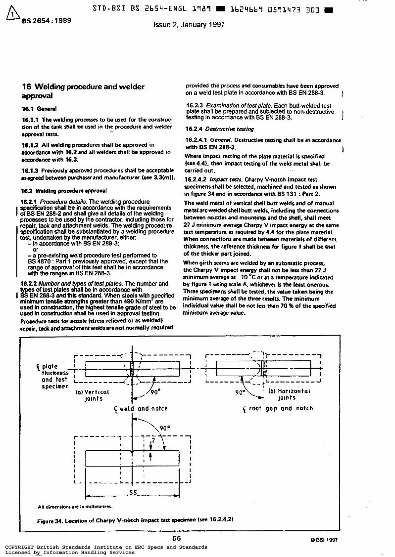
I
16 Welding procedure and welder approval
16.1 -Md
16.1.1 The welding processes to be used for the construc- tion of the tank shall be used in the procedure and welder approval tests.
16.19 All welding procedures shall be approved in accordane with 16.2 and all welders shall be approved in acwrdance with 16.3.
16.13 Previously approved procedures shall be acceptable asagreed betweenpurchaserand manufacturer (see 3.3(m)).
16.2 Welding proadun approval
16.2.1 Pmedum detai/s. The welding procedure specification shall be in accordance w~th the requirements of BS EN 288-2 and shall give all details of the welding processes to be used by the contractor, including those for repair, tack and attachment welds. The welding procedure specification shall be substantiated by a welding procedure test, undertaken by the manufacturer, either:
.-
- in accordance with BS EN 288-3;
- a preexisting weld procedure test performed to 6s 4870 : Part 1 prevlously approved, except that the range of approval of this test shall be in accordance with the ranges in BS EN 288-3.
or
16.2.2 Number and types of test plates. The number and
I R E N 288-3 and this standard. When steels with pcif ied minimum tensile stre S greater than 490 Wnrm are used in canstntdian, E highest tensile grade of steel to be used in construckm shall be used in approval testing.
tests for nozzle (stress relieved or as welded) repair, tack and attachment welds are not normally recluid
S of test plates shall be in accordanœ with
provided the process and consumables have been approved on a weld test plate in accordance with BS EN 288-3. I 16.2.3 Examination offesf plate. Each butt-welded test plate shall be prepared and subjected to non-destructive testing in accordance with BS EN 288-3. I 16.2.4 Destructive testing
16.2.4.1 General. Destructive testing shal l be in accordance with BS EN 288-3. Where impact testing of the plate material is specified (see 4.41, then impact testing of the weld metal shall be carried out. 16.2.4.2 / m p a c t t . & Charpy V-notch impact test specimens shall be selected, machined and tested as shown in figure 34 and in accordance with BS 131 : Part 2. The weld metal of verticaf shell butt welds and of manual metal arc welded shell butt welds, including the connections between nozzles and mountings and the shell, shall meet 27 J minimum average Charpy V impact energy at the same test temperature as required by 4.4 for the plate material. When connections are made between materials of different thickness, the reference thickness for figure 1 shall be that of the thicker part joined. When girth seams are welded by an automatic proas, t h e Charpy V impact energy shall not be less than 27 J minimum average a t -10 *C or at a tempcraturc indhted by figure 1 using scale A, whichever is the least onerous. Three specimens shall be tested, the value taken being the minimum average of the three results. The minimum individual value shall be not les than 70 96 of the specified minimum average value.
I
r------- I
plote I thickness7- 1 specimen
- - " - - 1 I
' [ I t - I l S -
and test L """" 4
(al Verttcal Joln t S
1 vetd and notch I
.""" 1" 1 1 ;
5 5
All dimensions M in millimetres.
r """_ 4 -lr """" "
-l
9 0 o y (bl Homontal JOlntS
{ root gap and not,ch
Figure 34. Loation of Charpy V-nbtch impad test specimen (see 16.2.4.2)
56 O BSI 1997 COPYRIGHT British Standards Institute on ERC Specs and StandardsLicensed by Information Handling ServicesCOPYRIGHT British Standards Institute on ERC Specs and StandardsLicensed by Information Handling Services
A STD-BSI BS ZbSq-ENGL 3987 m Lb24bb9 0593474 2 4 T m Issue 2, January 1997 BS 2654 : 1989
16.2.4.3 Retests. tf one or more Charpy specimen fails to comply with 16.2.4.2. three further specimens shall be prepared and tested. If any of the retests fail to comply with 16.2.4.2, the pro- d u r e shall be deemed not to comply with th is standard and a new prooedure shall be tested. NOTE. H u d n n r II llracommmded thal it is danonrtr.ted in the procedure teats t h t the hardness of the hsrt-8ffccted zone at the shell to bottom phteand of the weld matal. bat -dfwtd Z.0- .nd parmt plate m other l o w e i o n s in the drall. should not e x m d 300 HV (us¡* u) kg Iod). Where m n,s conditions m to IH encountered and YI awm- priate low M of hardness cannot k obtained, the most'suitable *rry to avoid suen corrosion crrking will be to pmtect the shell IO mwtu weid QCO and the a.ant uenicrt shell a d annular &te welds using m ~ p r ~ ~ h t a paint.
16.25 t3anges affrcting q6provsl. A welding procedure test shall be required when my of the changes specified
approved welding procedure. I in BS EN 288-3 and/or the following are made to an
(a) A change of brand of hydrogencontrolled welding electrode or in automatic welditq conrumabler, except for the wire in su"c welds. (b) F or a specified weld prepamtion in plates 12.5 mm thick and thidter, a chrngc of more than * 25 % in the number of NM If the cross-sectional area of the groove is increased, it is pcrmissibk to increase the number of runs in proportion to the increase in was. (cl For automtic girthseam weldirrg, a change from multipk runs per ride to ringle run per side. (dl For automatic girthoeam welding, a change from single arc to multiple arc or vice-versa.
16.3 Approval proœs for mlden
163.1 &nxwa/ of w/dm. Each welder shall k approved before welding on the tmk. A welder who has successfully welded the proadure test plate shall be considered to have ". 16.32 Appmvsl t em. E d welder shall be approved in
I accordanœ with 6s EN 287-1 and this standard, except for the following applications.
(al U n k specifically y!quired by the purchaser (see 32(m)). a mMcr who is oniy required to make filkt welds on the tank bottom, roof or shell plates not exceeding 12.5 mm thidtness, except for the hell-to- bottom wM, is not required to pass an approval test, but his standard of workmanship shall be such that the requirements of this standard are maintained. lb) Tack welding of shell, roof or bottom, where the tack weld shall be removed by gowing or shall be COmpfetely fured, can be carried out by nonspproved operators who are suitaMy i nmned and supervised to the Purchaser's satisfaction when permitted by the
purchaser (see 3.2(n)l. Othemrise, approved welders shall carry out these operations.
16.3.3 Examination of welders' test plates. Each butt-welded test-plate shall be tested in accordance with
16.3.4 Extent of wpval. A welder who has success- fully welded the s p e c i f d tests duIl be approved to the extent specified in BS EN 287-1 except that:
(a) a welder who has successfully welded the t e s t s using a basic coated electrode shall be approved to use rutile, allulosic or iron powder coated electrodes; (b) a welder who has successfully welded the tests wing a rutile coated electrode shall be approved to use cellu- losic or iron powder coated elactrode; (c) a change from single arc to multiple arc or vice w u for wddert operating automatic or mmi-automaic machines requires re-testing.
BS EN 287-1.
I
16.3.5 Records
16.3.5.1 Copies of the records of each welder's approval shall be available for examination on site by the purdurer (see 3.4(d)).
16.3.5.2 A welder who has been approved shall not be prevented from undertaking production W& pending examination of these rccocds, or artif¡ copia of these records, provided 1635.1 has been complied with.
17 Radiography
17.1 Application The proadure specified in this clause shall apply to the inspection of the joints listed in 17.3. Radiographic examination of fillet welds shall not be required.
17.2 Prepation for examirution Surface dressing of butt-welded seams is not normally required except that surface irregularities which may confuse or mask any objectionable defect shall be care- fully removed.
17.3 Extent of radiography per tank
17.3.1 The extent of radiography *all be not less than that listed in table 6 for ea& plate thickness, bu1 shall include one radiograph taken from the first completed vertical joint for each welding process and thickness, if differing by more than ?r 3 mm, welded by each welder. Thereafter, without regard to the number of welders working thereon, the same incidence of radiography shall be maintained. NOTE. The loution of the r.diographa ir to be determined in sgreamcnt with the purchaser.
O BSI 1997
57
COPYRIGHT British Standards Institute on ERC Specs and StandardsLicensed by Information Handling ServicesCOPYRIGHT British Standards Institute on ERC Specs and StandardsLicensed by Information Handling Services
STD-BSI BS 2b54-ENGL L989 m Lb24bb9 0591475 18b m
BS 2654 : 1989
Table 6. Extent of radiography per tank
Thinner plate thickness Vertical wdds and T-joints
Over 25 mm 1 O % of total seam length plus al l T-junctions t
Over 13 mm up to and a t least half of the including 25 mm 1 O % of total seam length,
radiographs to include T-junctions
seam length Up to and including 13 mm 1 % of total vertical
Annular plates over 10 mm - Annular plates over 8 mm up to and including 10 mm
Annular plates up to and - including 8 mm
-
I
Horizontal seams
2 % of seam length
2 % of seam length
1 % of seam length
Annular bottom butt welds.
-
All joints
Half the number of joints
A quarter of the number of joints, with a minimum of 4 radiographs
'The length to be radiographed shall consist of that length from the outside of the annular Plate to a POiW 250 mm inside the tank. t50 % of radiographs with film horizontal and 50 % of radiographs with film vertical.
17.3.2 Butt welds around the periphery of an insert plate shall be radiographed over the whole of their length. NOTE. When two or more tanks are erected in the same location for the same purchaser. either concurrently or consecutively, the initial radiographs of the work of each welder need only be taken on one tank. In addition. the total number of radiographs taken may be based on the aggregate length of welds for the same type and thickness in such a group of tanks rather than on the length in each tank, but with a minimum of 50 % of the coverage requirements given in table 6 on each tank.
17.4 Radiography procedure
17.4.1 Tehniques. Radiography shall be carried out in accordance with BS 2600 : Part 1 using techniques 1,2,3, 6 or 7 for plate thicknesses up to and including 19 mm and techniques 1 or 2 for plates thicker than 19 mm. NOTE. X-radiography is preferred to gamma-radiography because of the inherent low contrast of the latter. If, because of local conditions or special circumstances, gamma-radiography ir used the isotope employed will be Iridium 192.
17.4.2 Intensifying screns. Lead screens shall be used in all the techniques and their thicknesses shall be in accor- dance with table 3 of BS 2600 : Part 1 : 1983.
17.4.3 Radiographic film. Each film shall show clearly a minimum of 300 mm of weld length; it shall be centred on the weld and shall be sufficiently wide to permit adequate space for the location of identification markers and image quality indicator (IQI). Care shall be taken to ensure that films are carefully handled and stored: they should not be
subjected to mechanical or chemical damage and it is particularly important to guard against inadvertent expo- sure to sunlight, radiation or excessive heat.
17.4.4 Standard test radiograph. The exposing, film p r o cessing and handling procedures shall be demonstrated to the purchaser and shall be subject to his approval (see 3.4(e)). A standard test radiograph shall be prepared and shall be made available for inspection.
17.4.5 Image quality indkarors. To check the degree of definition and contrast achieved and to determine whether the minimum radiographic standard is being attained, an image quality indicator complying with BS 3971 shall be used with dimensions appropriate to the thickness of the weld. The method of assessing the radiographic sensi- tivity shalt be that described in BS 397 l.
17.4.6 Film locarion. The film during exposure shall be as close to the adjacent weld surface as is practicable.
17.4.7 ldenrificarion markers. Identification markers, the images of which will appear on the film, shall be placed adjacent to the weld at each spot examined and their locations accurately marked near the weld on the outside surface, so that a defect appearing on the radiograph may be accurately located.
17.4.8 Reference marker. There shall also be a suitable reference marker on each film.
17.4.9 Submission of radiography. All radiographs shall be submitted to the purchaser.
58 COPYRIGHT British Standards Institute on ERC Specs and StandardsLicensed by Information Handling ServicesCOPYRIGHT British Standards Institute on ERC Specs and StandardsLicensed by Information Handling Services
17.4.10 Radiographic standards. The defect acceptance levels given in table 7 shall be imposed during fabrication as a means of quality control. Areas found to be outside these limits shall be repaired in accordance with 15.14.
17.4.1 1 Record of radiographic examination
17.4.11.1 The eredon contractor shall make a record of all films, with their identification marks, preferably on a developed shell plate diagram. NOTE. Other agreed methods comparable with this diagram may be acceptable.
17.4.11.2 After completion of the tank, the films shall be retained for a minimum of 5 years.
1 Table 7. Acceptance levels for radiographic examination
1 Defect type I Permitted maximum
Crack
Lack of fusion
Incomplete penetration
Not permitted
Not permitted
Not permitted except as specified in 7.5.2
I Isolated pores I Uniformly distributed or localized porosity
Linear porosity
Wormholes, isolated
Wormholes, aligned
Individual slag inclusions parallel to major weld axis NOTE l . Inclusions to b e separated on the major axis by a distance equal to or greater than the length of the longer inclusion and the sum of the lengths of the inclusions shall not exceed the total weld length being examined
2 % by areac (as seen in a radiograph)
Linear porosity in vertical welds parallel to the axis of the weld may indicate lack of fusion or lack of penetration and therefore is not permitted
Length 3 6 mm
As linear porosity
Length > t
'Area to be considered should be the length o f the weld affected by porosity multiplied by the maximum width of the weld locally.
NOTE 2 . In this table the following symbols are used:
Q i s a defect diameter (in mm);
1 is the thickness of thinner plate being joined lin mm).
18 Testing
18.1 General
18.1.1 A comprehensive test procedure shall be specified and agreed between the purchaser and manufacturer (see 3.3(n)) . The water tes t procedure shall specify maximum filling rates, hold periods, emergency and normal emptying procedures, method of settlement measurement, limits for differential and maximum settlement of the foundations, minimum water temperatures, etc. (see A.5).
On completion of the test, the manufacturer in conjunc- tion with the purchaser shall review the settlement data and determine that the tank is fit for service. Consideration shall also be given to the effect of future settlements.
18.1.2 No connections shall be made between a tank and any product line until the tank and i t s appropriate mount- ings have been satisfactorily tested in accordance with 18.2 to 18.6.
18.2 Bottom testing
18.2.1 The bottom of the tank shall be tested for leaks using either of the methods in 18.2.2 or 18.2.3.
18.2.2 The bottom seams shall be tested by the vacuum box method using a pressure of 650 mbar absolute h e . 350 mbar of vacuum).
18.2.3 Alternatively,after the tank bottom and a t least the bottom course of shell plates have been welded, air shall be pumped beneath the tank bottom at a pressure sufficient to l i f t the bottom plates off the foundation. The pressure, which shall be 7 mbar maximum, shall be held by the construction of a temporary dam of clay or other suitable material around the tank periphery. Soap solution or other suitable material shall be applied to the joints for the detection of leaks.
18.2.4 The bottom and bottom-to-shell welds shall be made free of leaks as required by the purchaser (see 3.4(f)).
18.3 Mountings
18.3.1 Pneumatic testing of the reinforcing plates i s not required unless specified by the purchaser (see 3.2(0)), when it shall be done a t a pressure of 1 bar prior to the shell water test. For this purpose,"tapped holes of 12 mm diameter maximum shall be used and these holes shall be left open after testing,
18.3.2 The roof drain shall be installed prior to the hydraulic test on the tank and during this test the drain shall be examined to ensure that it i s not leaking due to external pressure.
59 COPYRIGHT British Standards Institute on ERC Specs and StandardsLicensed by Information Handling ServicesCOPYRIGHT British Standards Institute on ERC Specs and StandardsLicensed by Information Handling Services
BS2654:1989
18.4 Shell testing
18.4.1 The tank shall be tested by filling with water to the level specified in 7.2.1. The rate of filling shall not exceed that specified in the procedure. NOTE. Attention is drawn to the notes o f figure 1 relating to the minimum test water temperature and to the recommendations of A.5 relating to the rate of test water filling.
18.4.2 The manufacturer shall be informed by the purchaser of the quality of the water to be used and if necessary, any special cleaning or corrosion protection, e.g. inhibitor or cathodic protection (see 3.1 (k)).
18.4.3 Continuous inspection shall be maintained for the whole filling period. All leaks found shall be repaired with the water level a t least 300 mm below the point being repaired.
18.4.4 During emptying of test water, precautions shall be taken to ensure that the design vacuum is not exceeded.
18.5 Floating-roof testing
18.5.1 The centre deck plate, pontoon bottom plate and rim plate welded joints shall be tested by spraying with a penetrating oil, such as light gas oil, on the bottom side and inspecting visually on the top side and inside of rim plates.
18.5.2
18.5.2.1 Either of the methods of test specified in 18.5.2.2 or 18.5.2.3 shall be applicable.
18.5.2.2 The fillet welds connecting the bulkheads between pontoons to the inner and outer rim plates and to the pontoon bottom shall be examined for leaks using penetrating oil prior to the installation of the pontoon top plates. When continuously welded, the welds connecting the pontoon top plates shall be inspected visually for pinholes or defective welding.
18.5.2.3 Alternatively, when the compartments are completely welded, each completed compartment of pontoon roof shall be individually tested with an air pressure of 7 mbar gauge, a soapy water solution being applied to all welded joints under pressure which have not been previously tested with penetrating oil.
18.5.3 The roof shall be given a flotation test while the tank is being filled with water and emptied. During this test, the upper side of the lower deck and al l pontoon compartments shall be examined for leaks. Rainwater shall be prevented from entering the pontoon compartments during this test.
During the initial filling with product the purchaser shall check pontoon compartments and decks for any leaks
caused by the deeper immersion in the stored product than in the water (see 3.4(9)).
18.5.4 Pin-holes and/or defectivewelding in seams intended to be in contact with the product shall be corrected by welding. NOTE. Isolated pin-holes in seams not in contact with the product may be caulked mechanically.
18.5.5 The sealing mechanism shall be checked to ensure proper functioning over the full height of the shell.
18.6 Fixed-roof testing
18.6.1 When the tank shell i s tested with water the roof joints shall be tested by applying an internal air pressure equal to 7.5 mbar for non-pressure tanks and 3 mbar above the design pressure of the tank for pressure tanks.
In the case of column-supported roof tanks, the air test pressure shall be limited to that pressure equivalent to the weight of the roof plates unless the compression area has been determined in accordance with 8.5, using a design pressure of 7.5 mbar (see 2.12).
Soap solution or other suitable material shall be used for the detection of leaks. NOTE. Attention i s drawn to the need for careful control and monitoring of pressures during this testing. Climatic changes can cause sharp fluctuations in test pressures and provision should be made for the safe relief of pressure or vacuum in the event of such fluctuations.
18.6.2 Pressure and vacuum or free vents shall normally be installed after completion of the tank water test or alternatively shall be blanked-off during the testing of the roof. After installation or immediately following the roof pressure tes t a l l vents shall be carefully examined to ensure that all packing and blanks have been removed and that a l l moving parts function normally. NOTE 1. Anchorages. I f tank anchorages are provided, these should be checked and readjusted, i f necessary, with the tank full of water and prior to the air pressure test.
NOTE 2. Foondarions. Attention is drawn to the recommendations of A.5. When foundations are not constructed in accordance with appendix A it is still advisable that the recommendations in A.5 are adhered to.
Water filling should be stopped immediately there is evidence o f excessive abnormal or unexpected soil movement or the differen- tial or maximum settlements are tending to exceed those specified in the testing procedure. I f there is a risk of continuing excessive settlements or soil movement, the tank should be off-loaded.
Any tank showing evidence of leakage from the bottom during water test should be emptied immediately. The source of such leaks should be determined and rectified. Where there is a risk that the leakage may have caused washout of the foundation material, the foundations are to be inspected. The repair of the foundation should be the subject of special consideration and approval by the purchaser.
60 COPYRIGHT British Standards Institute on ERC Specs and StandardsLicensed by Information Handling ServicesCOPYRIGHT British Standards Institute on ERC Specs and StandardsLicensed by Information Handling Services
Appendices
Appendix A. Recommendations for tank foundations
A.l General
A . l . l The recommendations given in this appendix are intended to establish general principles for the design and construction of foundations under vertical oil storage tanks. They are offered as an outline of good practice and point out some precautions which should be observed in constructing such foundations.
A.1.2 Because of the wide variety of surface, sub-surface and climatic conditions, it obviously i s not practicable to establish design data to cover all situations and the allow- able soil loading should be decided for each individual case having regard to the type and s ize of tank. The design should be generally in accordance with CP 2004 and take account of the special nature of the soil/structure inter- actions and the definition of the load.
A.1.3 I f tank anchorages are required according to clause 10, suitable foundations are required. The design of these foundations should be based on the loadings specified by the tank designer.
A.2 Site design considerations
A.2.1 At any tank site, the nature of the sub-surface conditions should be known in order to determine the variation o f soil properties over the s i te and to estimate the amount of settlement that will be experienced. A s i te investigation should be carried out in accordance with BS 5930 to identify the ground conditions under the complete area of each tank to a depth over which signifi- cant settlements may occur. Where the founding material i s sound or weathered rock, the s i te investigation shall be supplemented by geophysical mapping of the tank pad formation.
Additional useful information can be obtained from a review of sub-surface conditions and the history of similar structures in the vicinity.
The allowable soil loading can then be decided in relation to the reliability of predictions of ultimate bearing capacity and the permissible settlements by a soil mechanics specialist.
A.2.2 The permissible settlement is the maximum allow- able design limits for the settlement of the foundation. These limits are to be agreed between the purchaser and the manufacturer for the maximum and differential settle- ment across the bottom and around the periphery of the tank. The considerations affecting the limits of permissible settlement are as follows.
(a ) The dimensions and aspect ratio of the tank.
(b) The type of tank, e.g. open-top tanks with pontoon type floating roofs will generally tolerate a much smaller differential settlement around the circumference than fixed-roof tanks. Tanks with column-supported roofs require special design considerations in the event
of significant bottom plate settlements (see 8.2.1).
(c) Economic considerations, e.g. savings of foundations costs versus the risk of excessive settlements and the possibility of future maintenance costs.
(d) The allowable relative movement of adjoining or related foundations or pipework.
(e) The difference in settlement between the periphery and the centre.
Settlement calculations are of limited accuracy even with detailed investigation and sophisticated analysis. Tanks should not therefore be designed to depend for their integrity on precise settlement predictions.
A.2.3 Maximum tank settlements can vary from a few millimetres to a metre or more. The initial settlement measured a t water test can be greatly exceeded during the l i fe of the tank particularly on weak slow draining sub-soils and the amount of settlement may also be affected by the cyclic nature of the load. The extent o f the differential settlement will depend on the uniformity or otherwise of the sub-soil, the stiffness of the tank and any interactive effects from adjacent tanks. The use of foundations with large permissible settlements should only be considered after a thorough site investigation and in consultation with soil mechanics specialists.
The following are some of the many variations in condi- tions which should, if a t all possible, be avoided for the construction of tank foundations. Where, from economic considerations or lack of alternative areas, they are unavoid- able, then they require special considerations.
(a) Sites where part of a tank may be on rock, undisturbed ground or other construction and part on fill; where the depth of required fill is variable; or where ground under part of the tank area has been precon- solidated.
(b) Sites on swampy or filled ground, or where layers of highly compressible material are below the surface.
(c) Sites where stability of the ground is questionable, such as adjacent to water courses, deep excavations or heavy loads, or on hillsides.
(d) Sites where tanks may be exposed to flood waters, resulting in possible uplift, displacement or scour.
Special consideration should also b e given to the effect on the foundation of heated tanks.
A.2.4 If the sub-soil supporting the foundation is weak and inadequate to carry the load of the filled tank without excessive settlement, the following methods should be considered.
61
(a) Removal and replacement of unsatisfactory material by suitable compacted fill.
(b) Improvement of the soft or loose materials by vibration, dynamic compaction or preloading with an overburden of other material.
(c) Sub-soil drainage with or without preloading.
(d) Stabilization by chemical or grout injection methods.
(e ) Provision of a reinforced concrete raf t with or without supporting piles.
COPYRIGHT British Standards Institute on ERC Specs and StandardsLicensed by Information Handling ServicesCOPYRIGHT British Standards Institute on ERC Specs and StandardsLicensed by Information Handling Services
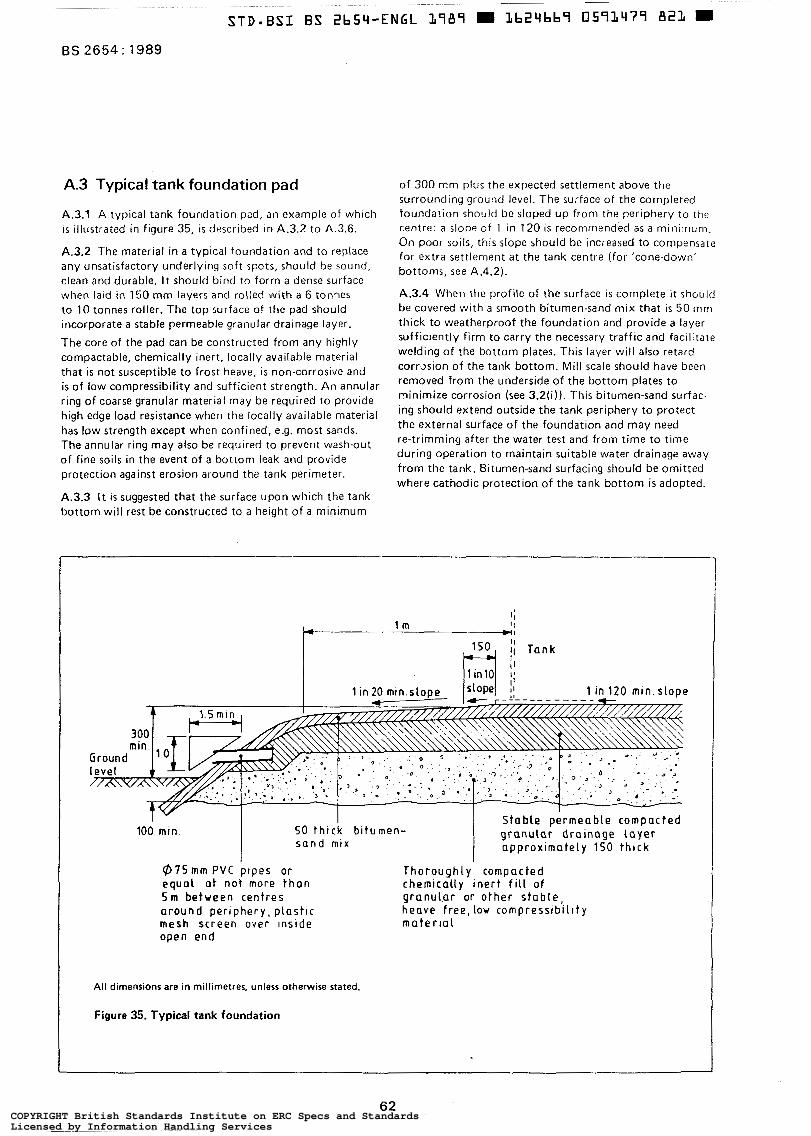
BS 2654: 1989
A.3 Typical tank foundation pad
A.3.1 A typical tank foundatlon pad, an example of which is illustrated in figure 35, is described In A.3.2 to A.3.6.
A.3.2 The material in a typical foundation and to replace any unsatisfactory underlying soft spots, should be sound, clean and durable. It should bind to form a dense surface when laid in 150 mm layers and rolled with a 6 tonnes to 10 tonnes roller. The top surface of the pad should incorporate a stable permeable granular drainage layer.
The core of the pad can be constructed from any highly compactable, chemically inert, locally available material that is not susceptible to frost heave, i s non-corrosive and is of low compressibility and sufficient strength. An annular ring of coarse granular material may be required to provide high edge load resistance when the locally available material has low strength except when confined, e.g. most sands. The annular ring may also be required to prevent wash-out of fine soils in the event of a bottom leak and provide protection against erosion around the tank perimeter.
A.3.3 I t is suggested that the surface upon which the tank bottom will rest be constructed to a height of a minimum
of 300 mm plus the expected settlement above the surrounding ground level. The surface of the completed foundation should be sloped up from the periphery to the centre: a slope o f 1 in 120 is recommended as a minimum. On poor soils, this slope should be increased to compensate for extra settlement at the tank centre ( for 'cone-down' bottoms, see A.4.2).
A.3.4 When the profile of the surface i s complete it should be covered with a smooth bitumen-sand mix that is 50 mm thick to weatherproof the foundation and provide a layer sufficiently firm to carry the necessary traffic and facilitate welding of the bottom plates. This layer will also retard corrxion of the tank bottom. Mill scale should have been removed from the underside of the bottom plates to minimize corrosion (see 3.2(¡)). This bitumen-sand surfac- ing should extend outside the tank periphery to protect the external surface of the foundation and may need re-trimming after the water test and from time to time during operation to maintain suitable water drainage away from the tank. Bitumen-sand surfacing should be omitted where cathodic protection of the tank bottom is adopted.
Groun level m
1 in 120 min slope
All dime
I - l I Stable permeable compacted 100 min. 50 thick bitumen- g r a n u l a r d r a i n a g e l a y e r s a n d mlx approxlmately 150 thick
nsi
I
Ø 7 5 m m P V C prpes o r equa l a t not more t h o n S m between centres around per iphery, plast lc mesh screen o v e r Inside open end
ons are in millimetres, unless otherwise stated.
I
Thoroughly compacted chemically inert f i l l of granuL.ar or o t h e r s t a b l e , heave free, low cornpressibillty m a t e r l a l
Figure 35. Typical tank foundation
1
62 COPYRIGHT British Standards Institute on ERC Specs and StandardsLicensed by Information Handling ServicesCOPYRIGHT British Standards Institute on ERC Specs and StandardsLicensed by Information Handling Services
A.3.5 A suitable bitumen-sand can be produced by hot- mixing in the followlng proportions b y mass:
1 (a ) 9 ? 0.5 % ( r n / r n ) non-toxic cut back bitumen i (¡.e. fluxed with kerosine and not creosote*);
(b) 10 5 1 .O % ( rn /m) filler: either limestone dust passing a sieve of nominal aperture size 75 pm complying with BS 410, or Portland cement;
( c ) 81 t 1.5 % ( m / m ) clean dry washed sand with the properties given in table 2 of BS 882, 1201 : Part 2 : 1973.
As an alternative to the sand, crushed rock types 1 to 7, slag or limestone in accordance with table 53 of BS 4987 : 1973 may be used.
Some variation of these proportions may be necessary to suit ambient temperature conditions, locally available materials, etc., and it is recommended that trial mixes be made in order to achieve the correct proportions to suit the particular case.
A.3.6 A series of 75 mm diameter PVC pipes should be placed around the perimeter of the drainage layer and protrude through the bitsand facing to the berm to give warning of any bottom plate leakage. The pipes should be at not more than 5 m intervals and the inlet should be covered with a mesh screen to prevent clogging by material from the drainage layer, In special cases it may be necessary to introduce an impermeable layer below the base of the foundation pad (see figure 35).
A.4 Modifications and alternatives to typical foundation pads
A.4.1 Where poor sub-soil conditions necessitate the use of a reinforced concrete raft and piled foundations, the raft should be designed in accordance with normal reinforced concrete practice (see CP 1 1 4 or CP 110) and surfaced with a reduced thickness of bitumen-sand mix as described in A.3.
A.4.2- Where a tank with a central internal bottom drainage sump is required:
(a) on hard ground where little settlement is expected, the tank foundation may be given a slight fall to the centre;
(b) on poor ground where considerable settlement is expected, special consideration should be given to the possibility of unacceptable tensile stresses developing in the bottom plates and in such cases a foundation constructed as recommended in A.4.1 should be used.
A.4.3 For high-pressure tanks, it may be necessary to prevent uplift of the shell due to the combined effects of vapour pressure and wind movement by means of an anchorage around the shell built into a suitable concrete ring or raft.
Where the foundation design incorporates a ring beam, care should be taken to ensure that the relative settlement characteristics o f the fing wall and the infill are not such as to result in excessive differential settlement local to the inner wall of the ring beam. Consideration may need to be given to the provision of a hinged transition slab in this area. A minimum thickness of 50 mm of bitumen-sand should be maintained over the concrete.
A.5 Water testing
While it i s normal practice to t e s t all tanks by filling with water before commissioning, this filling should be done under controlled conditions to ensure that foundation failure does not occur during filling. The water test pressure is an integral part of the foundation design and should be agreed with a soil mechanics specialist.
All tank tests will be carried out to provide adequate measured load/settlement records.
The first tank in a new area will be the most critical and subsequent testing arrangements on other tanks should be adjusted in the light of the first test results where the tanks are on similar sub-soil conditions.
A minimum of four points on tanks under 25 m diameter and eight points on tanks over 25 m diameter should be marked around the base of the tank for subsequent levelling reference. A greater number of points may be required for large tanks and/or where a complex settlement pattern i s expected. Before water is added to the tank, the levels a t each reference point should be recorded. Permanent refe- rence levels have to be established in locations unaffected by tank loading.
As a guide, when ground conditions are good and settle- ment is expected to be negligible, the tank may be half- filled with water as quickly as practicable, having regard to its size, the pumping facilities and water supply available. No further filling should proceed until levels have been taken and checked against the readings when empty to ensure that no uneven settlement is occurring in which case filling can proceed until the tank i s three-quarters full, when level readings should be taken again. Provided the tank remains level with only slight settlement due to load, filling can then proceed until the tank is full, when level readings are again repeated. The full water load should be main- taind for 48 h and provided levels remain sensibly consis- tent, the tank can be offloaded prior to calibration for service. Provided this tank is satisfactory and subsequent tanks are founded similarly, the level readings a t one-half and three-quarters capacity may be omitted for small tanks of less than 25 m diameter. On weak ground where signifi- cant settlements may be expected or where the initial factor of safety against slip failure is low, the rate of filling should be greatly reduced. Some guidance on the Safe heights for initial filling and where pauses in filling are
*Creosote fluxed bitumen i s not considered to be acceptable in view o f i t s acid content.
63
~~
COPYRIGHT British Standards Institute on ERC Specs and StandardsLicensed by Information Handling ServicesCOPYRIGHT British Standards Institute on ERC Specs and StandardsLicensed by Information Handling Services
BS 2654 : 1989
required may be deduced from the soil investigation and from piezometric monitoring of pore water pressures. Typically, where settlements of over 300 mm may be expected, water should be added to the tank a t about 0.6 m per day until about 3 m of water i s stored. At such a head, filling should cease and levels a t the reference points should be recorded daily. Daily reference point levels should be plotted on a timescale to follow the pattern of settlement.
When the daily rate of settlement begins to decrease, water should be added to the tank in decreasing increments of head when the settlement graph shows that the rate of settlement under each new increment of load is reducing. As the water load nears the full capacity of the tank, water should preferably be added after an early morning check of reference levels so that further readings can be taken during the day and the tank offloaded should the rate of settlement increase unduly. On very weak soils, these tests may extend over considerable periods and where such conditions apply, the tank builder should be advised so that adequate provisions can be made in his programme for the necessary testing and acceptance procedure.
Some guidance on safe heights for initial filling and where pauses are desirable may be deduced from the shear strength data and strata thicknesses of the underlying soil.
In carrying out such test procedures adequate arrangements should be made for the emergency disposal of water if off- loading became necessary. Discharge should be to a safe area, clear of al l foundations and structures and such that no danger of erosion can occur.
Appendix B. Recommendations for the design and application of insulation
vacuum effects, differential thermal expansion and hydraulic pressure expansion do become serious. Bands longer than about 12 m are not recommended without special care in band design and there are instances of failure due to the inadequacy of such methods of securing insulation and cladding to the tank.
Wherever possible the insulation system should be secured by direct attachment to the tank. This can be achieved by sprayed-on insulation, by foaming in situ or by mechanical attachments to the tank. While welding of studs or stee l members to small tanks may be satisfactory, welding on large tanks can materially affect the design and integrity of the construction but it i s permissible when considered as part of the tank design. The use of adhesives is a possible alternative method of fastening attachments where welding cannot b e permitted but i s subject to temperature limita- tions and should only be carried out by specialists in this field.
The basis of all welded-on attachments should be to provide a series of points disposed circumferentially on the tank a t a number of vertical intervals, on to which vertical and/or horizontal members may be fastened. The support structure and welded-on attachments should be designed so as to transmit back to the tank al l the dead loads and super- imposed wind loads expected to be experienced a t the location concerned.
Design aspects which are not dealt with in this appendix should comply with the requirements in the main body of the text .
On existing tanks, careful consideration needs to be given in such cases t o the safety aspects in providing the attach- ments in order to take account, where corrosion has taken place, of the corroded shell thickness and to provide an adequate safety margin in the design of the system as a whole.
B.l General The basic consideration necessary on methods to be employed to achieve acceptable insulation systems are set out below. These insulation systems suitable for large tanks
(a) man-made mineral fibre or preformed foam block with cladding;
This appendix is intended for new tanks but may also be include: used for existing tanks. While not attempting to specify in detail the insulation systems themselves, it i s intended to provide a sound basis on which these systems can be specified and particularly to facilitate the provision of suitable mechanical supports for the insulation material, these supports to form an integral part of the tank fabrica- tion. The recommendations cover storage tanks operating a t temperatures above ambient and of a size where banding is unreliable and direct fixing to the tank is necessary.
In order that a correct choice may be made of type and method of providing the insulation attachments, it is emphasized that, where new tanks are concerned, early consideration of the need for insulation is essential so that the necessary provisions for it can be integrated with the tank design and erection programme. This consideration should also include the possible need for insulation of the tank roof.
On small tanks the problem of attaching the insulation securely is not serious but on tanks above 10 m to 15 m diameter problems due to wind loading, associated
(b) in situ foam behind cladding; (c) foam/cladding laminate sheets;
(d) sprayed foam.
This standard recognizes that for a particular installation a proprietary system of insulation including fixing and weather protection may be suitable. I f a proprietary system is offered, specific acceptance should be obtained, the element of the system that constitutes the mechanical support which forms part of the tank fabrication being clearly identified.
In this appendix, separate references are made to the tank designer, ¡.e. the organization responsible for carrying out the design of the tank, and the tank fabricator, ¡.e. the organization responsible for the erection of the tank, but it is recognized that this distinction i s only necessary in the event that the two parties are not the same,
64 COPYRIGHT British Standards Institute on ERC Specs and StandardsLicensed by Information Handling ServicesCOPYRIGHT British Standards Institute on ERC Specs and StandardsLicensed by Information Handling Services
STD-BSI B S 2bSq-ENGL L787 W Lb24bb9 059L482 3 L b m
B.2 Design considerations
B.2.1 General
The design of an insulation system, which incorporates the insulating material, i t s means of attachment to the tank and its means of weather protection, should take into account the following:
(a) the product in the storage tank under its operating conditions;
(b) the storage tank itself;
(c ) the insulation materials;
(d) the mechanical support system associated with the insulation system;
(e) the means whereby the insulation and i t s support system isenabled to withstand environmental conditions.
The insulation system is to be agreed between tank designer, insulation contractor and the purchaser.
The system including its mechanical supports and fastenings should bedesigned to withstand the mechanical and thermal stresses to which it will be subjected resulting from all known factors including those listed in B.2.2 to 8.2.5. These factors should be assumed to occur simultaneously.
Because relatively large forces are involved in providing a secure system for the attachment of insulation to the outside of storage tanks, the mechanical support arrange- ments can be extensive and will frequently be attached to the outer face of the tank itself. The design of the attachment of the support system should be subject to care- ful scrutiny by the tank designer and he should ensure that a minimum of attachments are used. Preliminary discussions with insulation contractors are often helpful in identifying suitable systems and the type of supporting arrangements likely to be necessary.
B.2.2 Dead load
Dead loads result from the weight of al l parts of the insulation system.
B.2.3 Wind loading
In the design of the insulation system account is to be taken of the effect of wind loading using CP 3 : Chapter 5 : Part 2 as a basis for estimating wind pressures. The para- meters required for using CP 3, including the basic wind speed appropriate to the site and the factors S1, S2 and S3, should be agreed between the tank designer and the purchaser and this information given to the insulation contractor. Unless otherwise specified, the parameter S3 is to be based on a life of 25 years. A t present CP 3 does not give pressure coefficients for the full range of shape factors that are of interest in large tank insulation and further data are required to include smaller height/diameter ratios, appropriate roof profiles and the effect of proximity where more than one tank is involved.
The tank designer should agree with the purchaser the basis on which the wind loading calculations are to be made.
BS 2654 : 1989
8.2.4 Thermal expansion
The possibility of relative thermal movement between the tank and the insulation system should be taken into account in the design. The purchaser will state the range of operating temperatures.
B.2.5 Movements due to hydrostatic pressure
The pressure of the tank contents causes slight bulging which may account for an increase in tank diameter of the order 0.1 %;this may need to be taken into account in designing the insulation system and the actual value is to be provided by the tank designer.
9.3 Mechanical support arrangement
B.3.1 General
The mechanical supports may be divided into the following.
(a) Primary mechanical supports, where the members form part of the mechanical support system and are directly attached to the tank surface.
(b) Secondary mechanical supports, where the members form part of the mechanical support system and are not directly attached to the tank but are fixed to the primary support members or to other secondary support members.
Suitable mechanical supports for the insulation system should be provided by one of the following means or a combination thereof.
(1 ) Primary supports, welded to the tank, to which the insulation system is attached either directly or by secondary supports.
(2) A structural frame that is substantially self-supporting.
(3) Primary supports fixed to the tank by adhesive, to which the insulation system i s attached.
Welding is the preferred method of attachment but may not always be possible especially where existing tanks are to be insulated. While in each case the system chosen is to be with the agreement of all parties concerned, the direct responsibilities will be as follows unless otherwise agreed.
(i) In cases (1) and (3), tne insulation contractor should agree with the tank designer the locations of the supports to which the insulation system i s to be attached and the loads that will be transmitted to the tank and the basis on which his calculations have been made or other referencedata he hasused. If required, he should provide details of the calculations to be approved by the tank designer.
(i¡) In case (2) where an external structure or frame is intended, this will be regarded a s part of the insulation system to be provided by the insulation contractor. The design and erection procedure should be agreed with the tank designer but will be the responsibility of the insulation contractor unless otherwise agreed.
The dimensions of the mechanical supports normal to the surface to which the insulation is to be attached should be an agreed size to suit the insulation thickness.
65 COPYRIGHT British Standards Institute on ERC Specs and StandardsLicensed by Information Handling ServicesCOPYRIGHT British Standards Institute on ERC Specs and StandardsLicensed by Information Handling Services
BS 2654 : 1989
6.3.2 Supports attached by welding The primary mechanical supports will form part of the tank structure and the tank designer will be responsible for approving the material and the welding procedures. The tank fabricator will be responsible for fixing the primary supports to the tank surface. Welding of primary supports to the tank will be completed before hydraulic testing is carried out. The number of multiple-welded insulation support attachments to high tensile steel (minimum specified tensile strength 460 N/mm2 1 shells should be minimized. In any case the centre-to-centre distance between them should not be less than 3 m. Al l welds should be ground smooth and magnetic particle crack detected (see 11.15). These supports should take one of the following forms.
(a) Pads (not smaller than 1 O0 mm square) with corners rounded to a radius not less than 12 mm, spaced not closer than 150 mm to any other weld and welded along horizontal edges only [see figure 36).
(b) Angles or plates welded on-edge to the tank having a circumferential length of not less than 100 mm a t a spacing not closer than 150 mm to any other weld, welded along horizontal edges only (see figure 37).
Materials for the primary supports are to be selected according to the requirements of this specification. In cases (a) and (b), secondary supports may be welded or attached to the pads, plates or cleats. In the case of circumferential angles, the welds should not be closer than 150 mm to other horizontal welds. The welding will be carried out by approved welders and the welding and non-destructive testing procedures should be agreed between the tank designer and the purchaser.
Plates welded on-edge or pads will be placed in horizontal rows at a suitable vertical pitch which will be, typically, 2 m to 3 m. Horizontal support angles, whether primary or secondary, should be of a minimum size 40 mm x 40 mm x 5 mm and of radial dimension compatible with the insulation system (see 8.8.1.3). The spacing between adjacent members will not be more than 5 15 mm from the specified dimensions with the spacing between the highest and lowest members being not more than 2 25 mm from the specified dimensions. The outer leg of the member should be pointing downwards in order to shed water during construction.
6.3.3 External structural frame
A structural frame suitably attached to the tank structure a t the top and bottom may be used in certain circum- stances. This may be in contact with the tank or external to the insulation.
B 3 4 Supports attached by adhesive
6.3.4.1 General. I f an adhesive system is used, the materials and procedure are to be such as to withstand the working conditions including both mechanical and thermal condi- tions. The surface of the tank in the vicinity of the fixing a;ld the contact surface of the member to be fixed should
be shot-blasted and the adhesive applled only to clean dry metal and strictly in accordance with the instructions of the adhesive manufacturer, account being taken of the suitability of the adhesive formulation for the ambient conditions, particularly temperature, a t the time of application. Procedure, qualification and acceptance tests are to be carried out to the satisfaction of the purchaser.
B.3.4.2 Procedure tests. Tests will be carried out using the proposed procedure to demonstrate to the satisfaction of the purchaser that it is capable of providing 12 times the strength required as calculated from the wind loading and any other loading i f applicable (see B.2.2). Such tests should include exposure for not less than 2 months a t the temperature a t which the surface of the tank will reach in service and temperature cycling i f appropriate.
6.3.4.3 Qualification tests. Only trained personnel are to be used in making the adhesive joints and each individual to b e employed on this work should carry out the qualifi- cation test within one month of commencement of adhesive joint preparation. Six joints will be prepared in the manner proposed for the contract and in the presence of such persons as may be agreed between the purchaser and the tank designer. When tested according to the agreed procedure the strength of these joints should exceed 12 times the minimum required strength.
6.3.4.4 Acceptance tesrs. Records are to be kept to permit identifications of supports attached with adhesive from each separate batch. A proof load will be applied equal to three times the calculated load. If more than 5 % of the batch has failed, the whole batch is to be removed and replaced.
8.3.5 Secondary support members
The design of secondary support members and their attach- ments to the primary support will be the responsibility of the insulation contractor who will obtain the agreement of the tank designar to the design and means of attachment. It should be made clear in enquiries to the insulation contractor whether or not he is to provide the material forming the secondary supports for which he is taking the responsibility. Holes made in any support member welded to the tank should be drilled, not punched, and i f self- tapping screws are used, they should be not larger than 6 mm diameter,
8.3.6 Roof insulation
Early consideration of the possible need for roof insulation is important. A roof construction of adequate stiffness is required with the slope everywhere adequate to permit satisfactory weather protection of the insulation.
In the case of tanks with an insulated shell, where the tank roofs are not insulated, calculations should be carried out t o check the stresses in the roof supporting structure caused by the difference in temperature of the roof plates and the supporting structure, e.g. when cold rain falls on roof plates.
66 COPYRIGHT British Standards Institute on ERC Specs and StandardsLicensed by Information Handling ServicesCOPYRIGHT British Standards Institute on ERC Specs and StandardsLicensed by Information Handling Services
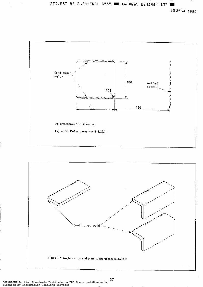
BS 2654 : 1989
Continuous( w e l d s \
,/
\ \ \ R 1 2
100 I m
W e l d e l
All dimensions are in millimetres.
Figure 36. Pad supports (see B.3.2(a))
Figure 37. Angle section and plate supports (see B.3.2tb))
67 COPYRIGHT British Standards Institute on ERC Specs and StandardsLicensed by Information Handling ServicesCOPYRIGHT British Standards Institute on ERC Specs and StandardsLicensed by Information Handling Services
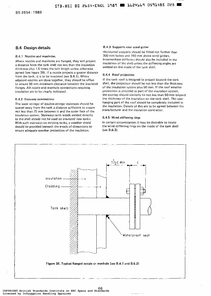
BS 2654 : 1989
6.4 Design details
6.4.1 Nozzles and manholes
Where nozzles and manholes are flanged, they will project a distance from the tank shell not less than the insulation thickness plus 1.5 times the bolt length unless otherwise agreed (see figure 38). I f a nozzle projects a greater distance from the tank, it is to be insulated (see B.6.1). Where adjacent nozzles are close together, they should be offset to ensure 50 mm minimum clearance between the insulated flanges. All nozzle and manhole connections requiring insulation are to be clearly indicated.
8.4.2 Stairway connections
The inner stringer of double-stringer staircases should be spaced away from the tank a distance sufficient to ensure not less than 75 mm between i t and the outer face of the insulation system. Stairways with treads welded directly to the shell should not be used on insulated new tanks. With such stairways on existing tanks, a weather shield should be provided beneath the treads of dimensions to ensure adequate weather protection of the insulation.
lnsu lat lon --
B.4.3 Supports near wind girder
Horizontal supports should be fitted not further than 300 mm below and 150 mm above wind girders. Intermediate stiffeners should also be included in the insulation of the shell unless the stiffening angles are welded on the inside of the tank shell.
6.4.4 Roof projection
If the tank roof is designed to project beyond the tank shell, the projection should be not less than the thickness of the insulation system plus 50 mm. If the roof weather protection is provided as part of the insulation system, the overlap should similarly be not less than 50 mm beyond the thickness o f the insulation on the tank shell. The over- hanging part of the roof should be completely included in the insulation. Details of this are to be agreed between the manufacturer and the insulation contractor.
B.4.5 Wind stiffening rings
In certain circumstances it may be desirable to locate the wind stiffening rings on the inside of the tank shell (see 8.6.3).
lnsu lat lon -
'Waterproo f seal
Figure 38. Typical flanged nozzle or manhole (see B.4.1 and B.6.2)
68 COPYRIGHT British Standards Institute on ERC Specs and StandardsLicensed by Information Handling ServicesCOPYRIGHT British Standards Institute on ERC Specs and StandardsLicensed by Information Handling Services
8.4.6 External shell wind girders and bottom-to-shell insulation
External shell wind girders and bottom-to-shell insulation represent a discontinuity in the envelope of the tank and require detailed consideration by the insulation system designer in conjunction with the tank designer to avoid the following.
(a ) Unacceptable thermal gradients in the tank plate material due to part exposure.
(b) Consideration of potential corrosion due to such areas forming a lodgement for corrosive fluids. Consideration should be given to enveloping al l such structural elements with the insulation, particularly if the storage temperature i s high, but each case i s to be taken on i t s merits,
B.5 Corrosion protection
The presence of insulation prevents inspection of the tank surface and priming is therefore required before the insulation is applied. The tank shell and welded attach- ments should be dry, free from grease and loosely adhering particles and coated with a suitable primer, all to a specification agreed by the purchaser. If the roof i s to be insulated, two coats of primer are recommended. I f shop priming is employed, care should be taken to make good any defects in the priming caused during site fabrication.
The responsibility for this work is to be clearly determined a t the time the tankage contract is let.
In the case of in situ spraying or foaming, the paint system should be such that it i s compatible with the foam system and unaffected by any foaming reaction or in-service condition. Where foam insulation is used with fire retardant formulations, protection against the possibility of halogen- induced accelerated corrosion should be considered.
B.6 Insulation
B.6 .1 General
Insulation practice should be in accordance with R S 5970. Insulation thickness should be specified by the purchaser or designed to meet the purchaser's heat loss requirements, Unless the stresses produced are unacceptable, the insula- tion should terminate approximately 150 mm from the tank base to avoid corrosion and to allow inspection a t the bottom of the tank (see figure 39). Where the stresses are unacceptable, foamed glass slabs set in bitumen or other suitable adhesive may be used for insulation of the tank shell below the lowest horizontal support.
The shell insulation should f i t closely under the roof over- lap and be sealed against ingress of water (see figure 40). Special care should be taken where roof insulation is to be carried out to avoid corrosion (see 8.4.4, B.7.3 and 6.8.41. When the roof i s not insulated, a check should be made as to whether the thermal stresses in the roof supporting structure,caused by thedifference in temperature between roof plates and supporting structure, are acceptable (see figure 40).
B.6.2 Nozzle connections and manholes
Where these project up to a distance equal to the sum of the insulation thickness plus depth of cladding profile plus 1.5 times the bolted length, they are to be insulated with the main shell/roof insulation (see figure 38). Where the projection is in excess of the above, they will be insulated and finished prior to the application of insulation to the shell/roof (see figure 41).
8.6.3 Wind stiffening rings The wind stiffening rings and their associated supports should be enclosed by the shell insulation to minimize the temperature difference; figure 42 shows a typical construction local to a wind stiffening ring.
69 COPYRIGHT British Standards Institute on ERC Specs and StandardsLicensed by Information Handling ServicesCOPYRIGHT British Standards Institute on ERC Specs and StandardsLicensed by Information Handling Services
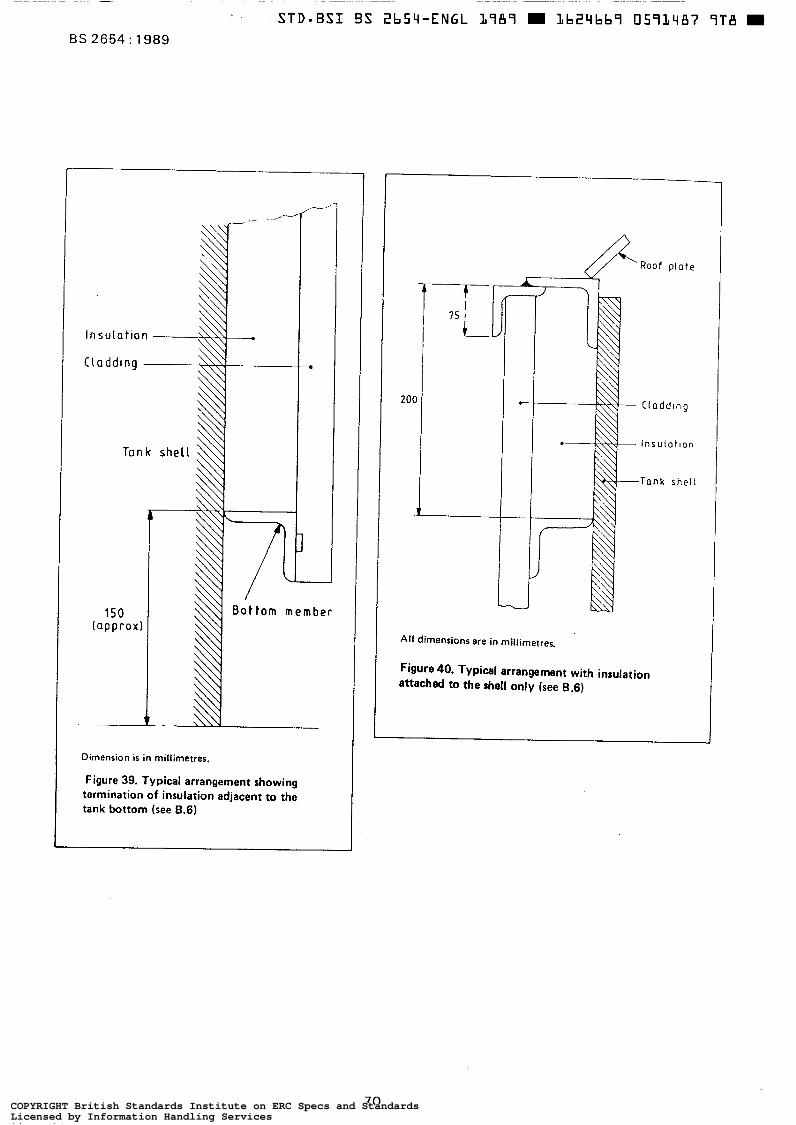
Tank she1
Dimension is in millimetres.
Figure 39. Typical arrangement showing termination of insulation adjacent to the tank bottom (see B.6)
Roof plate
CLaddlng
lnsu lo t lon
Tank shell
All dimensions are in millimetres.
Figure 40. Typical arrangement with insulation attached to t h e shell only (see B.6)
70 COPYRIGHT British Standards Institute on ERC Specs and StandardsLicensed by Information Handling ServicesCOPYRIGHT British Standards Institute on ERC Specs and StandardsLicensed by Information Handling Services
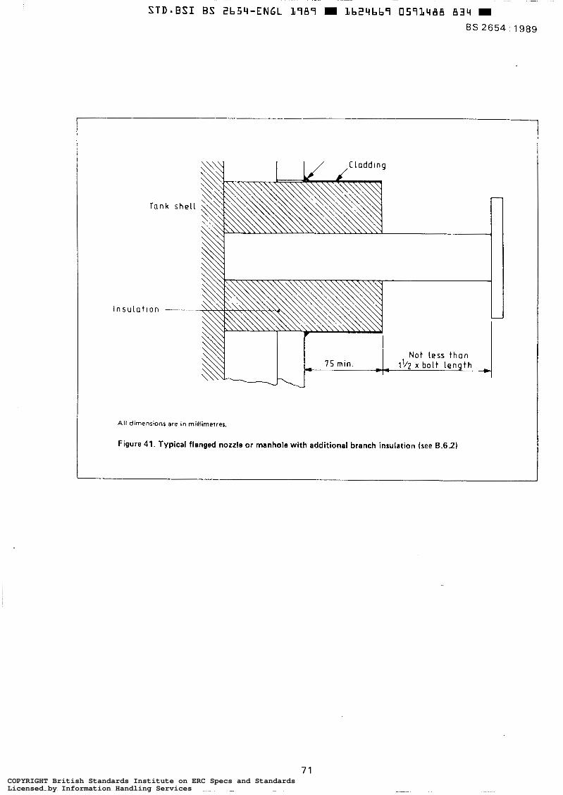
1
I I / ,CLaddtng
Tank she[ L
l n s u l a t l o n -
All dimensions are in rnillirnetres.
Figure 41. Typical flanged nozzle or manhole with additional branch insulation (see B.6.2)
71 COPYRIGHT British Standards Institute on ERC Specs and StandardsLicensed by Information Handling ServicesCOPYRIGHT British Standards Institute on ERC Specs and StandardsLicensed by Information Handling Services
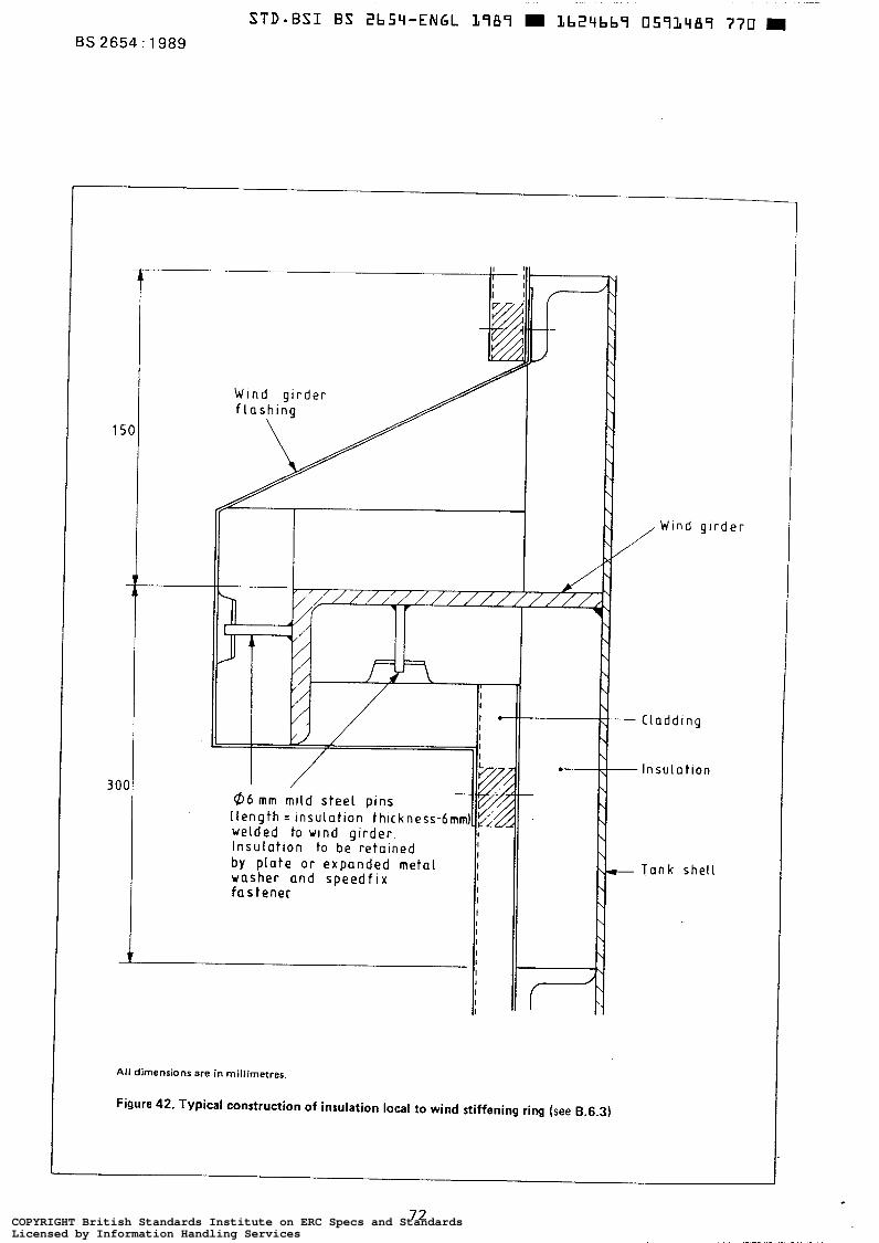
BS 2654: 1989
b y p l a t e or e x p a n d e d m e t a l washer a n d s p e e d f i x I f a s t e n e r I
I
I
I I I I I I I
All dimensions are in millimetres.
Figure 42, Typical construction of insulation local to wind stiffening ring (see B.6.3)
d e r
72 COPYRIGHT British Standards Institute on ERC Specs and StandardsLicensed by Information Handling ServicesCOPYRIGHT British Standards Institute on ERC Specs and StandardsLicensed by Information Handling Services
B.7 Cladding
B.7.1 General
Cladding is a feature common to most insulation systems. The effectiveness of the insulation depends particularly on the care applied in the design and installation of the cladding. The type a.nd quality of cladding should be selected bearing in mind environmental conditions on either side.
I t i s essential that al l cladding be kept clean, free from grease, free from corrosion and dry on the inner surface prior to erection and until the installation is complete and all joints are well sealed.
8.7.2 Side-wall cladding
Care should be taken to prevent direct contact between stairway supports and cladding. Cut-outs in cladding for stairway supports should be sealed with mastic to prevent ingress of water. Sealant i s not normally considered necessary for vertical or horizontal joints in the cladding.
The tank side-wall cladding should be troughed aluminium or galvanized steel sheet attached to the support members. The minimum depth of trough is to be 25 m. Corrugated sheet having sinusoidal profiles should receive special attention in view of the need to avoid the ingress of water and to ensure adequate fixing. The minimum thickness of sheet should be:
(a) 0.9 mm for aluminium;
(b) 0.7 mm for galvanized or plastics-coated steel.
Galvanized steel sheet will be grade 22, coating type H l complying with BS 2989. Aluminium sheet should be to ES 1470 - 3103, ES 4300/6 - 3105 or BS 1470 - 5251 of grade H4 or harder or be of the grades specified in BS 4868. In any horizontal ring, adjacent sheets should have a minimum overlap of one trough profile and be secured with bulb-type blind pop-rivets a t not greater than 100 mm pitch. The rivets should be of material compatible with the cladding and such as to secure the overlap to accommodate the maximum design wind-suction.
Each horizontal ring of cladding should overlap the lower horizontal ring by a minimum of 75 mm and be secured with bulb-type blind pop-rivets a t a distance not less than 25 mm from the edges of the sheets. Sheets should be secured to support members using fasten- ings designed to accommodate the agreed wind loading and tank movements due to thermal expansion and hydro- static pressure.
B.7.3 Roof cladding
Metal cladding for the tank roof should be plain or embossed and the minimum thickness should be:
(a) 1.2 mm for aluminium;
(b) 0.9 mm for galvanized or plastics-coated steel.
All overlaps in the cladding are to be not less than 100 mm and be so arranged as to shed water, All joints should contain a continuous strip of a sealant approved by the purchaser and be secured by bulb-type blind pop-rivets of a material compatible with the cladding. The pop-rivets should be a t a maximum pitch of 75 mm.
Consideration should be given to properly draining rain- water over the edge of the roof so that i t does not a f fec t the integrity of the insulation system. (See figure 40.)
B.8 Securing insulation materials
B.8.1 Slab or block insulation with metal cladding
B.8 .1 .1 Bonded man-made mineral fibre with metal cladding. The insulation should consist of bonded mineral wool complying with BS 3958 : Part 5, the bulk density being not less than 48 kg/m' . The insulation material should be supported on the horizontal support members and held in place with 1 mm (minimurn) galvanized t i e wires for use with galvanized steel cladding and 0.5 mm (minimum) stainless steel wire for use with aluminium cladding or plastics-coated steel cladding. The insulation slabs should be fitted tightly between the horizontal support members with al l edges closely butted and vertical joints offset from those in adjacent courses. The t i e wires should be at a pitch not greater than 450 mm with a minimum of two tie wires '
per insulation slab.
6.8.1.2 Other slab or block insulation with metal cladding. Preformed slabs of polyurethane or polyisocyanurate may be used on the tank sides as an alternative to mineral wool, the method of fixing being similar to that described for mineral wool slabs (see 8.8.1.1) or by adhesives suitable for the operating temperature.
For certain circumstances foamed glass blocks may be required. Where this material is used, the blocks should be held in place with 20 mm x 0.8 mm bands of approved material a t centres not exceeding 450 mm. The bands should be secured to vertical t i e bars fitted to the horizon- ta l support members at centres not exceeding 12 m. Alternatively, adhesives suitable for the operating tem- perature may be used.
B.8 .1 .3 Horizontal supports. The'horizontal supports will have a radial width adequate for support of the insulation and agreed with the insulation contractor.
B . 8 . 2 In situ foam behind metal cladding
The type of foam and i t s physical and thermal properties are to be agreed between the insulation contractor, the tank designer and the purchaser. The cladding should comply with 6.7.2 or 8.7.3. The cladding may be supported as recommended in 8.7.2 or may be spaced from the tank using foamed blocks, stuck to the side-wall, of agreed type and size and of thickness equal to the minimum insulation
73 COPYRIGHT British Standards Institute on ERC Specs and StandardsLicensed by Information Handling ServicesCOPYRIGHT British Standards Institute on ERC Specs and StandardsLicensed by Information Handling Services
thickness. Provision will be made, in the latter system, to restrain the cladding against distortion and movement due to pressure exerted by the foaming operation. Due regard should be taken in this latter system o f the attachment of the insulation to the tank shell and cladding, to ensure adequate resistance to wind loads, Approved flashings or other means of weather protection should be provided where metal connections for walkways, etc. penetrate the insulation. All pipe connections should be insulated prior to fitting the cladding. The insulation a t the roof edge i s to terminate as shown in figure 40.
The sequence of the cladding and foaming procedure, the method of injecting the foam and the foaming pattern are to be approved by the tank designer and the purchaser.
The insulation contractor will define the weather and substrate temperature limits necessary for satisfactory foaming.
Means should be agreed between the insulation contractor, the tank designer and the purchaser for establishing and checking the satisfactory quality of the foam.
8.8.3 Sprayed foam
The type of foam and i t s physical and thermal properties should be agreed between the insulation contractor, the tank designer and the purchaser.
The insulation contractor will define the weather and substrate temperature limits necessary for satisfactory spraying.
The thickness of the sprayed foam is not to be less than the nominal design thickness. The standard of finish of the sprayed foam will be agreed with the purchaser and the insulation contractor and samples of foam o f the agreed appearance prepared and retained for reference. Means should be agreed between the insulation contractor, the tank designer and the purchaser for establishing and checking the satisfactory quality of the foam.
I f a weatherproof finish is required, this should be applied over the foam insulation preferably b y spraying a f t e r the foam i s fully cured. The weatherproof finish should be applied in two coats of different colours. Where extra resistance to mechanical damage and/or bird attack i s required, an agreed reinforcing medium should be applied between the two layers o f the finish. The weatherproof finish will have a class 1 surface spread-of-flame rating when tested to BS 476 : Part 7. The insulation contractor is to agree suitable means for weather protecting the foam a t the top edge of the tank.
The tank should be le f t uninsulated for a distance of approximately 150 mm from the base.
8.8.4 Roofs Where mineral wool and metal cladding form the insulation, the mechanical support system should comply with 5.3.5 and B.3.6 and be of upstand not less than the thickness of the insulation and not greater than this thickness plus 5 mm. Metal cladding is to be as described in B.8.2 and be fixed to the support system to withstand wind loading and wind induced vibrations. The fastening will be compatible with the cladding.
Additional reinforcement of the insulation system may be necessary where access may be required.
It may be convenient to apply foam insulation to the roof, either sprayed or foamed in situ, even if a mineral wool or other system is specified for the tank sides.
B.9 Fire hazard
Possible fire hazards exist during construction and operation when organic plastics foam insulation is used. Although some materials and formulations are more resistant to fire than others, they are nevertheless still combustible and may not necessarily al leviate a fire hazard.
COPYRIGHT British Standards Institute on ERC Specs and StandardsLicensed by Information Handling ServicesCOPYRIGHT British Standards Institute on ERC Specs and StandardsLicensed by Information Handling Services
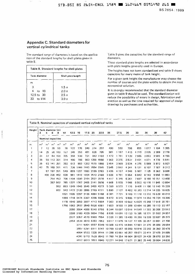
Appendix C. Standard diameters for vertical cylindrical tanks
The standard range of diameters is based on the applica- tion of the standard lengths for shell plates given in table 8.
1 Table 8 . Standard lengths for shell plates I 1 Tank diameter 1 Shell plate length I
m 3
12.5 to 30 2.0 71 4 to 10 1.5 TI
3.0 TI 33 to 114 2.5 r
m 3
12.5 to 30 2.0 71 4 to 10 1.5 TI
3.0 TI 33 to 114 2.5 r
Table 9 gives the capacities for the standard range of diameters.
These standard plate lengths are selected in accordance with plate lengths generally used in Europe.
The heights have not been standardized and table 9 shows capacities for every metre of tank height.
For a given tank height the manufacturer may choose the number of courses and the plate widths to obtain the most economical solution.
It is strongly recommended that the standard diameter given in table 9 should be used. The standardization will reduce the possibility of errors in design, fabrication and erection as well as the time required for approval of design drawings by purchasers and authorities.
Table 9. Nominal capacities of standard vertical cylindrical tanks
Height
m
1
2
3
4
5
6 7
8
9
10
1 1
12
13
14
15
16
1 7
18
19
20
21
22 23
24
25
rank diameter (ml 3 4 6 8 10 12.5 15 17.5 20 22.5 25 27.5 30 33 36 39 42
Uorninal capacities
n’ m’ m’ m’ m’ m’ m’ m’ m’ m3 m’ m’ m’ m’ m 3 m’ m’
7 12 28 50 78 122 176 240 314 397 490 593 706 855 1017 1 1 9 4 1 3 8 5
14 25 56 100 157 245 353 481 628 795 981 1 187 1 413 1 710 2035 2 3 8 9 2 7 7 0
21 37 84 150 235 358 530 721 942 1192 1 4 7 2 1 781 2 120 2 565 3053 3 5 8 3 4 156
28 50 113 201 314 490 706 962 1256 1590 1963 2375 2 8 2 7 3 421 4 071 4 778 5 541
35 62 141 251 392 613 883 1202 1570 1988 2 4 5 4 2 9 6 9 3 5 3 4 4 2 7 6 5 0 8 9 5 9 7 2 6 9 2 7
12 75 169 301 471 736 1060 1443 1884 2385 2 9 4 5 3 5 6 3 4 2 4 1 5 1 3 1 6 1 0 7 7 1 6 7 8 3 1 2
87 197 351 549 859 1237 1683 2199 2783 3436 4157 4948 5987 7125 8362 9698
100 226 402 628 981 1413 1924 2513 3180 3 9 2 6 4 7 5 1 5 6 5 4 6 8 4 2 8 1 4 2 9 5 5 6 1 1 0 8 3
254 452 706 1104 1590 2164 2827 3578 4 4 1 7 5 345 6 3 6 1 7 6 9 7 9 160 10 751 12468
282 502 785 1227 1767 2405 3141 3976 4 9 0 8 5 9 3 9 7 0 6 8 8 5 5 2 1 0 1 7 8 1 1 9 4 5 1 3 8 5 4
552 863 1349 1943 2645 3455 4373 5 3 9 9 6 5 3 3 7 775 9408 11196 13 140 1 5 2 3 9
603 942 1472 2120 2886 3769 4771 5 890 7 127 8 4 8 2 1 0 263 1.2214 14335 16625
1021 1595 2297 3126 4084 5168 6 3 8 1 7 721 9 1 8 9 11 178 13232 15529 18010
1099 1718 2414 3367 4398 5566 6 8 7 2 8 3 1 5 9 8 9 6 1 1 9 7 4 1 4 2 5 0 16 724 19396
1178 1840 2650 3607 4712 5964 7363 8909 10602 12829 15268 ‘17918 20781
1256 1963 2827 3848 5026 6361 7853 9503 11309 13684 16285 19113 22167
2086 3004 4088 5340 6759 8344 10097 12016 14540 17303 20308 23552
2208 3180 4329 5654 7156 8 8 3 5 10 691 12 723 15 395 18 321 21 502 24937
2331 3357 4570 5969 7554 9 3 2 6 11 285 13430 16250 19339 22697 26323
2454 3534 4810 6283 7952 9817 11879 14137 17105 20357 23891 27 708
3711 5051 6597 8349 10308 12473 14844 17961 21 375 25086 29094
3887 5291 6911 8747 10799 13067 15550 18816 22393 26 280 3 0 4 7 9
4064 5532 7225 9144 11 290 13661 16 257 19671 23411 27475 31865
4241 5772 7539 9542 11 780 14 254 16 964 20 527 24 428 28 670 33 250
4417 6013 7853 9940 12271 14848 17671 21 382 25446 29864 34636
75 COPYRIGHT British Standards Institute on ERC Specs and StandardsLicensed by Information Handling ServicesCOPYRIGHT British Standards Institute on ERC Specs and StandardsLicensed by Information Handling Services
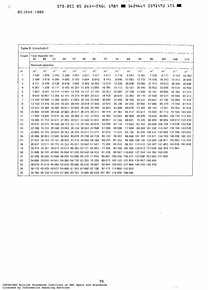
BS 2654 : 1989
Table 9. /concluded)
Height
m
1
2
3
4
5
6
7
8
9 10
1 1
12
13
14
15
16
17
18
19
20
21
22
23
24
25
Tank diameter (m) 45 48 51 54 57 60 66 72 78 84 90 96 102 108 114
Nominal capacities
m’ m’ m’ m’ m’ m’ m’ m’ m’ m’ m’ m’ m’ m’ m’
1590 1 8 0 9 2 0 4 2 2 290 2551 2827 3 421 4 071 4 778 5 5 4 1 6 3 6 1 7 238 8 171 9 150 10 202
3 1 8 0 3 6 1 9 4085 4 5 8 0 5 1 0 3 5 6 5 4 6 8 4 2 8 142 9 5 5 6 11083 12723 14476 16342 10312 20404
4 7 7 1 5 4 2 8 6128 6 8 7 0 7655 8 4 8 2 1 0 2 6 3 12214 14335 16625 19085 21 714 24513 28468 30606
” -
6 3 6 1 7 2 3 8 8 1 7 1 9 1 6 0 1 0 2 0 7 1 1 3 0 9 1 3 6 8 4 16285 1 9 1 1 3 22167 25446 28952 32685 36624 40808
7952 9047 10214 11451 12758 14137 17 105 20357 23891 27708 31808 36191 40856 45 780 5 1 0 1 0
9542 10857 12 256 13 741 1 5 3 1 0 16 964 20527 24428 2 8 6 7 0 33 250 38 170 43 429 49027 5 4 9 3 6 61 212
11 133 12666 14 299 16031 17862 19 792 23948 28500 33448 38 792 44532 50667 57 198 6 3 0 9 2 71 414
12723 14476 16342 18321 20414 22619 27369 32571 38 226 44334 50893 57905 65370 73 240 8 1 6 1 6
14313 16 285 18385 20611 22965 25446 30 790 36643 43005 49875 57 255 65 143 73541 82404 91818
15 904 18 095 20428 22902 25 517 28 274 34 211 40 714 47 783 55 417 63 617 72382 81 712 91 560 102020
17494 19905 22470 25192 28069 31 101 37633 44786 52561 60959 69978 79620 89883 100 716 112222
19 085 21 714 24513 27 482 30621 33 929 41 054 48 857 57 340 66 501 76 340 86 858 98 055 109872 122 424
20675 23 524 26 556 29 772 33 172 36 756 44 475 52 929 62 118 72042 82 702 94 096 106 226 119028 132 626
22266 25333 28599 32063 35724 39584 47896 57000 66896 77584 89064 101335 114397 128 184 142828
23856 27143 30642 34353 38276 42411 51317 61072 71675 83126 95425 108573 122569 137340 153030
25446 28952 32685 36643 40828 45238 54739 65143 76453 88668 101 787 115811 130740 146496 163232
27037 30762 34 727 38933 43379 48066 58160 69215 81 232 94 209 108 149 123049 138911 155662 173434
28627 32571 36770 41223 45931 50893 61581 73 286 86010 99751 114510 130287 147082 164808 183636
30218 34381 38813 43514 48483 53 721 65002 77358 90788 105 293 120872 137526 155 254 173964
31808 36191 40856 45804 51035 56548 68423 81429 95567 110835 127 234 144 764 163425
33399 38000 42899 48094 53586 59376 71844 85501 100345 116317 133596 152002 171596
34989 39810 44941 50384 56138 62203 75 266 8 9 5 7 2 105 123 121918 139957 159240
36579 41619 46984 52675 58690 65030 78687 93644 109902 127460 146319 166479
38 170 43429 49027 54965 61 242 67858 82108 97 715 114680 133002
39 760 45 238 51070 57255 63793 70685 85529 101 787 119458 138544
76 COPYRIGHT British Standards Institute on ERC Specs and StandardsLicensed by Information Handling ServicesCOPYRIGHT British Standards Institute on ERC Specs and StandardsLicensed by Information Handling Services
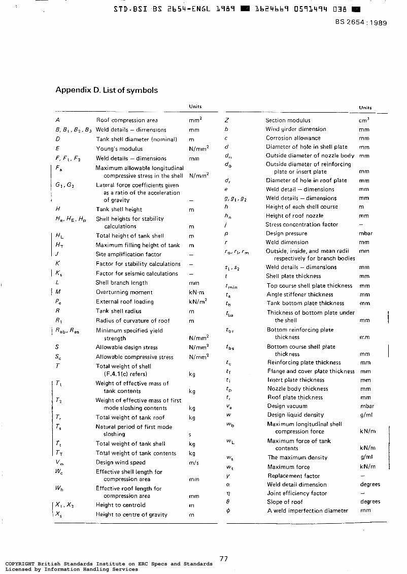
Appendix D. List of symbols
Units Units
A Roof compression area mm2
B, B I , B z , B3 Weld details - dimensions mm
S
S C
T
Tank shell diameter (nominal)
Young‘s modulus
Weld details - dimensions
Maximum allowable longitudinal compressive stress in the shell
Lateral force coefficients given as a ratio of the acceleration of gravity
Tank shell height
Shell heights for stability calculations
Total height of tank shell
Maximum filling height of tank
Site amplification factor
Factor for stability calculations
Factor for seismic calculations Shell branch length
Overturning moment
External roof loading
Tank shell radius
Radius of curvature of roof
Minimum specified yield
Allowable design stress
Allowable compressive stress
Total weight of shell
strength
(F.4.1 (c) refers)
Weight of effective mass of tank contents
Weight of effective mass of first mode sloshing contents
Total weight of tank roof
Natural period of first mode sloshing
Total weight of tank shell
Total weight of tank contents
Design wind speed
Effective shell length for compression area
Effective roof length for compression area
Height to centroid
Height to centre of gravity
m
N/mm*
mm
N/ m m’
-
m
m
m
m -
-
- mm
kN.m
k N/m2
m
m
N/mm2
N/mm2
Nimm'
kg
kg
kg
kg
S
kg
k g mls
mm
mm
m
m
Section modulus cm3 Wind girder dimension mm Corrosion allowance mm Diameter of hole in shell plate mm Outside diameter of nozzle body mm Outside diameter of reinforcing
plate or insert plate mm Diameter of hole in roof plate mm Weld detail - dimensions mm Weld details - dimensions mm Height of each shell course m Height of roof nozzle mm Stress concentration factor - Design pressure mbar Weld dimension mm Outside, inside, and mean radii mm
Weld details - dimensions mm Shell plate thickness mm
Top course shell plate thickness mm Angle stiffener thickness mm Tank bottom plate thickness mm
Thickness of bottom plate under
respectively for branch bodies
the shell mm I thickness r, m
thickness mm I Bottom reinforcing plate
Bottom course shell plate
Reinforcing plate thickness Flange and cover plate thickness Insert plate thickness Nozzle body thickness Roof plate thickness Design vacuum Design liquid density
Maximum longitudïnal shell compression force
Maximum force of tank contents
The maximum density
Maximum force Replacement factor Weld detail dimension Joint efficiency factor Slope of roof A weld imperfection diameter
mm mm mm mm mm mbar g/m I
k N/m
kN/m
g/m I
kN/m - degrees - degrees mm
77 COPYRIGHT British Standards Institute on ERC Specs and StandardsLicensed by Information Handling ServicesCOPYRIGHT British Standards Institute on ERC Specs and StandardsLicensed by Information Handling Services
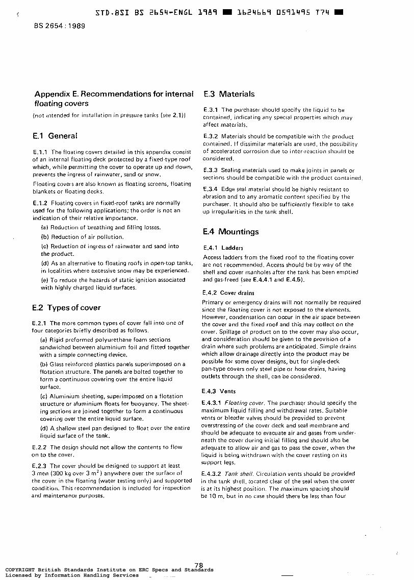
STD-ES1 ES Zb54-ENGL L789 L b 2 4 b b S 059L495 T 7 4 m BS 2654: 1989
Appendix E. Recommendations for internal floating covers (not intended for installation in pressure tanks (see 2.1))
E.l General
E . l . l The floating covers detailed in this appendix consist of an internal floating deck protected by a fixed-type roof which, while permitting the cover to operate up and down, prevents the ingress of rainwater, sand or snow.
Floating covers are also known as floating screens, floating blankets or floating decks.
E.1.2 Floating covers in fixed-roof tanks are normally used for the following applications; the order is not an indication of their relative importance.
(a) Reduction of breathing and filling losses.
(b) Reduction of air pollution.
(c) Reduction of ingress of rainwater and sand into the product.
(d) As an alternative to floating roofs in open-top tanks, in localities where excessive snow may be experienced.
(e) To reduce the hazards of stat ic ignition associated with highly charged liquid surfaces.
E.2 Types of cover
E.2.1 The more common types of cover falt into one of four categories briefly described as follows.
(a) Rigid preformed polyurethane foam sections sandwiched between aluminium foil and fitted together with a simple connecting device.
(b) Glass reinforced plastics panels superimposed on a flotation structure. The panels are bolted together to form a continuous covering over the entire liquid surface.
(c) Aluminium sheeting, superimposed on a flotation structure or aluminium floats for buoyancy. The sheet- ing sections are joined together to form a continuous covering over the entire liquid surface.
(d) A shallow steel pan designed to float over the entire liquid surface of the tank.
E.2.2 The design should not allow the contents to flow on to the cover.
E.2.3 The cover should be designed to support a t least 3 men (300 kg over 3 m’) anywhere over the surface of the cover in the floating (water testing only) and supported condition. This recommendation is included for inspection and maintenance purposes.
E.3 Materials
E.3.1 The purchaser should specify the liquid to be cantained, indicating any special properties which may affect materials.
E.3.2 Materials should be compatible with the product contained. If dissimilar materials are used, the possibility of accelerated corrosion due to inter-reaction should be considered.
E.3.3 Sealing materials used to make joints in panels or sections should be compatible with the product contained
E.3.4 Edge seal material should be highly resistant to abrasion and to any aromatic content specified by the purchaser. I t should also be sufficiently flexible to take up irregularities in the tank shell.
E.4 Mountings
E.4.1 Ladders
Access ladders from the fixed roof to the floating cover are not recommended. Access should be by way of the shell and cover manholes after the tank has been emptied and gas-freed (see E.4.4.1 and E.4.5).
E.4.2 Cover drains
Primary or emergency drains will not normally be required since the floating cover i s not exposed to the elements. However, condensation can occur in the air space between the cover and the fixed roof and this may collect on the cover. Spillage of product on to the cover may also occur, and consideration should be given to the provision of a drain where such problems are anticipated. Simple drains which allow drainage directly into the product may be possible for some cover designs, but for single-deck pan-type covers only steel pipe or hose drains, having outlets through the shell, can be considered.
E.4.3 Vents
E.4.3.1 Floating cover. The purchaser should specify the maximum liquid filling and withdrawal rates. Suitable vents or bleeder valves should be provided to prevent overstressing of the cover deck and seal membrane and should be adequate to evacuate air and gases from under- neath the cover during initial filling and should also be adequate to allow air and gas to pass the cover, when the liquid is being withdrawn with the cover resting on i t s support legs.
E.4.3.2 Tank shell. Circulation vents should be provided in the tank shell, located clear of the seal when the cover is at i t s highest position. The maximum spacing should be 10 m, but in no case should there be less than four
COPYRIGHT British Standards Institute on ERC Specs and StandardsLicensed by Information Handling ServicesCOPYRIGHT British Standards Institute on ERC Specs and StandardsLicensed by Information Handling Services
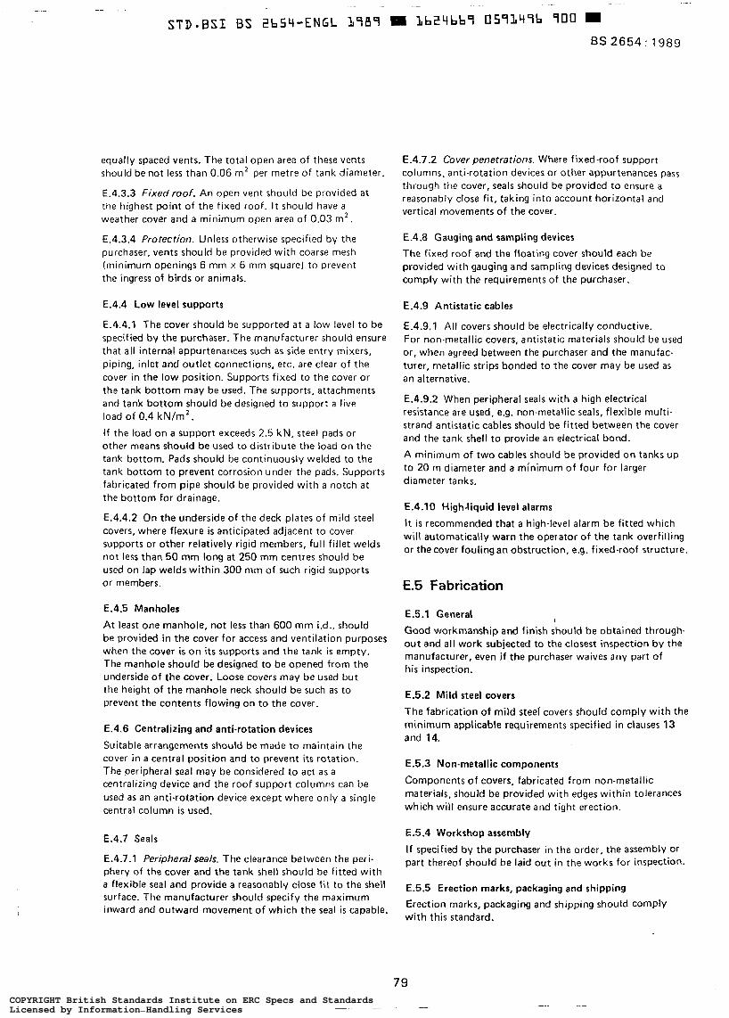
equally spaced vents. The total open area of these vents should be not less than 0.06 m’ per metre of tank diameter
E.4.3.3 Fixed roof. An open vent should be provided at the highest point of the fixed roof. It should have a weather cover and a minimum open area of 0.03 m* .
E.4.3.4 Protection. Unless otherwise specified by the purchaser, vents should be provided with coarse mesh (minimum openings 6 mm x 6 mm square) to prevent the ingress of birds or animals.
E.4.4 Low level supports
E.4.4.1 The cover should be supported a t a low level to be specified by the purchaser. The manufacturer should ensure that all internal appurtenances such as side entry mixers, piping, inlet and outlet connections, etc. are clear of the cover in the low position. Supports fixed to the cover or the tank bottom may be used. The supports, attachments and tank bottom should be designed to support a live load of 0.4 kN/m’.
I f the load on a support exceeds 2.5 kN, steel pads or other means should be used to distribute t h e load on the tank bottom. Pads should be continuously welded to the tank bottom to prevent corrosion under the pads. Supports fabricated from pipe should be provided with a notch at the bottom for drainage.
E.4.4.2 On the underside of the deck plates of mild steel covers, where flexure is anticipated adjacent to cover supports or other relatively rigid members, full fillet welds not less than 50 mm long a t 250 mm centres should be used on lap welds within 300 mm of such rigid supports or members.
E.4.5 Manholes
At least one manhole, not less than 600 mm ¡.d., should be provided in the cover for access and ventilation purposes when the cover is on i t s supports and the tank is empty. The manhole should be designed to be opened from the underside of the cover. Loose covers may be used but the height of the manhole neck should be such as to prevent the contents flowing on to the cover.
E.4.6 Centralizing and anti-rotation devices
Suitable arrangements should be made to maintain the cover in a central position and to prevent i t s rotation. The peripheral seal may be considered to act as a centralizing device and the roof support columns can be used as an anti-rotation device except where only a single central column is used.
E.4.7 Seals
E.4.7.1 Peripheral seals. The clearance between the peri- phery of the cover and the tank shell should be fitted with a flexible seal and provide a reasonably close fit to the shell surface. The manufacturer should specify the maximum inward and outward movement of which the seal i s capable.
E.4.7.2 Cover penetrations. Where fixed-roof support columns, anti-rotation devices or other appurtenances pass through the cover, seals should be provided to ensure a reasonably close fit, taking into account horizontal and vertical movements of the cover.
E.4.8 Gauging and sampling devices
The fixed roof and the floating cover should each b e provided with gauging and sampling devices designed to comply with the requirements of the purchaser,
E.4.9 Antistatic cables
E.4.9.1 All covers should be electrically conductive. For non-metallic covers, antistatic materials should be used or, when agreed between the purchaser and the manufac- turer, metallic strips bonded to the cover may be used as an alternative.
E.4.9.2 When peripheral seals with a high electrical resistance are used, e.g. non-metallic seals, flexible multi- strand antistatic cables should be fitted between the cover and the tank shell to provide an electrical bond.
A minimum of two cables should be provided on tanks up to 20 m diameter and a minimum of four for larger diameter tanks.
E.4.10 High-liquid level alarms
I t i s recommended that a high-level alarm be fitted which will automatically warn the operator of the tank overfilling or the cover fouling an obstruction, e,g. fixed-roof structure.
E.5 Fabrication
E.5.1 General I
Good workmanship and finish should be obtained through- out and a l l work subjected to the closest inspection by the manufacturer, even if the purchaser waives any part of his inspection.
E.5.2 Mild steel covers
The fabrication of mild steel’ covers should comply with the minimum applicable requirements specified in clauses 13 and 14.
E.5.3 Non-metallic components
Components of covers, fabricated from non-metallic materials, should be provided with edges within tolerances which will ensure accurate and tight erection.
E.5.4 Workshop assembly
If specified by the purchaser in the order, the assembly or part thereof should be laid out in the works for inspection.
E.5.5 Erection marks, packaging and shipping
Erection marks, packaging and shipping should comply with this standard.
79 COPYRIGHT British Standards Institute on ERC Specs and StandardsLicensed by Information Handling ServicesCOPYRIGHT British Standards Institute on ERC Specs and StandardsLicensed by Information Handling Services
BS 2654 : 1989
E.6 Erection
E.6.1 Rectification of damage to materials
Any damaged material should be rectified by the contrac- tor prior to erection, to the satisfaction of the purchaser.
E.6.2 Method of erection
The method of erection for the floating cover should be submitted by the manufacturer or contractor for the approval of the purchaser, if such approval has not already heen given in writing by the purchaser.
E.6.3 Circularity
In the construction of the floating cover, every care should be taken to minimize distortion or lack of circularity due to welding or other reasons. The clearance between the periphery of the cover and the tank shell should be uniform and comply with the dimensional requirements specified for the seal (see E.4.7.1).
E.7 Testing
E.7.1 Where applicable, before a floating cover is put into operation, it should be carefully tested for liquid tightness. Lap-welded joints in mild steel covers may be tested by the vacuum box method or by the use of high penetrating oil.
E.7.2 On completion, the tank should be filled with water, to check that the cover and seals travel freely to the full operating height and that the cover is free from leaks.
E.7.3 Manholes in the fixed roof should be kept closed during testing in wet weather, since any ingress of rain- water might lead to misleading conclusions on water- tightness.
E.7.4 Any damp spot on the cover should be taken as an indication of a possible leak.
Time may be necessary for leaks to become evident and checks should therefore be made a t frequent intervals, particularly during the first metre of filling.
E.7.5 All leaks detected during testing should be rectified to the satisfaction of the purchaser or his representative.
E.8 Operation
E.8.1 Access to the cover
During operation, no access to the tank and floating cover should be permitted, and the tank and cover should be cleaned and gas-freed before access is permitted for maintenance purposes. It is recommended that this is indicated near the tank manholes.
E.8.2 Periodic inspection The cover should be inspected for leaks, when in the top position, from a suitable manhole in the fixed roof. It is
recommended that this inspection be carried out during the first filling and subsequently a t three-monthly intervals. I t i s also recommended that, where fitted, the antistatic cables be examined to ensure that the electrical bond between the floating cover and the tank shell i s intact (see E.4.9.2).
E.8.3 Use of side entry mixers
Side entry mixers should be allowed to operate only when the floating cover i s a t a level where the normal function- ing of the cover will not be affected.
Appendix F. Recommendations for the design of venting systems
F.l General
This appendix gives recommendations for the normal vacuum, normal pressure and emergency venting of fixed. roof tanks with or without internal floating roofs constructed to comply with this British Standard.
Provision is made to enable evaluation of venting require. ments arising from the following sources.
(a) Normal vacuum venting requirements resulting from the maximum r a t e of export of product from the tank. (b) Normal vacuum venting requirements resulting from the maximum anticipated decrease in tank surface temperature.
(c) Normal pressure venting requirements resulting from the maximum anticipated rate of import of product to the tank.
(d) Normal pressure venting requirements resulting from the maximum anticipated increase in tank surface temperature.
(e) Emergency pressure venting requirements resulting from the exposure of the tank to an external fire.
Any additional causes of normal venting arising from process considerations should be quantified and added to the venting requirements listed in (a) to (e).
F.2 Normal venting
F.2.1 General
The total normal venting has to cater for a t least the sum of product movement and thermal effects.
F.2.2 Normal vacuum venting
F.2.2.1 The normal vacuum venting requirement associated with the maximum rate of product export should be 1 .O m3 of free air per hour for each 1 .O m3 /h of product export rate for products of any flash point.
COPYRIGHT British Standards Institute on ERC Specs and StandardsLicensed by Information Handling ServicesCOPYRIGHT British Standards Institute on ERC Specs and StandardsLicensed by Information Handling Services
F.2.2.2 The normal vacuum venting requirement associated wi th the maximum anticipated rate of tank surface tem- perature decrease should be:
( a ) G4000 m3 capacity: 0.18 m3 of f ree air per hour for each 1 m3 of capacity;
(b) > 4000 m3 capacity: 0.61 m3 of free air per hour for each 1 m' of shell and roof area.
F.2.3 Normal pressure venting
F.2.3.1 For products with a flash point of 38 "C or above, the normal pressure venting requirements associated with the maximum rate of product import should be 1 .O7 m3 of free air per hour for each 1 .O m3/h of product import rate.
F.2.3.2 For products with a flash point below 38 " C , the normal pressure venting requirements associated with the maximum ra te of product import should be 2.14 m3 of free air per hour for each 1 .O m3 /h of product import rate,
F.2.3.3 For products with a flash point of 38 "C or above, the normal pressure venting requirements associated with the anticipated rate of tank surface temperature increase should be 60 % of the values specified in F.2.2.2.
F.2.3.4 For products with a flash point below 38 "C, the normal pressure venting requirements associated with the anticipated maximum rate of tank surface temperature increase should be as recommended in F.2.2.2.
F.3 Emergency venting
F.3.1 Tanks with a frangible roof joint No provision need be made for emergency venting for fixed-roof tanks which have a shell to roof joint which is considered frangible according to the provisions of F.4.
F.3.2 Tanks without a frangible roof joint
F.3.2.1 Without additional protection. For tanks not provided with additional protection as indicated in F.3.2.2, the total rate of emergency venting should be as given in table 10. Full credit should be taken for the venting capacity provided for normal venting since thermal effects can be disregarded during a f i re as it can be assumed that no product movement will take place at that time.
F.3.2.2 Tanks with additionalprotection. The total rate of emergency venting should be multiplied by the appropriate factor when the following forms of protection are provided.
( a ) A factor of 0.5 when drainage away from the tank is provided.
(b) A factor of 7.5/t,, but limited to a maximum value of 0.075 (where t , is the thickness of the insulation (in mm)) when external shell insulation is provided that is considered non-combustible, does not decompose a t temperatures below 500 "C and is resistant to damage from fire water impingement.
The provision of any water cooling system will not result in a reduction in the vent ing requirements.
F.4 Frangible roof-to-shell joint
F.4.1 Tanks without anchorages
For the roof-to-shell joint of tanks without anchorages to be considered frangible (see F.3.1) the following should apply.
(a) The continuous fillet weld between the roof plates and the top curb angle should not exceed 5.0 mm.
(b) The slope of the roof sheeting adjacent to the top curb should not exceed 1 in 5 . (c) The effective cross-sectional area of the curb A (in mm2) as shown in figure 7 should not exceed:
7.07 x 10⁻³ T A =
where
tan O
T i s the total weight of shell, shell stiffening and roof framework supported by the shell but excluding the roof sheeting (in kg);
0 is the slope of roof meridian a t roof-to-shell connection (in degrees).
This may result in a curb area less than that required by 8.5.6.
F.4.2 Tanks with anchorage
In addition to the recommendations of F.4.l(a) and (b), the curb area provided should be checked to ensure failure a t a pressure which wil l not exceed the permitted design stresses in the holding down anchors, tank shell and the roof plating. Curb failure is assumed to occur at a compressive stress of 220 Nlmm2 (¡.e. use S, = 220 N/mmz in curb area equation in 8.5.2 to calculate failure pressure).
F.5 Means of venting
F.5.1 Normal venting
F.5.1.1 Normal venting should be accomplished by a pressure relief valve, a vacuum relief valve, a pressure vacuum (PV) valve or an open vent with or without a flame-arresting device complying with F.5.1.2 to F.5.1.7.
F.5.1.2 Relief valves equipped with a weight and lever are not recommended.
F.5.1.3 PV valves are recommended for use on atmos- pheric storage tanks in which a product with a flash point below 38 "C is stored and for use on tanks containing a product that i s heated above i t s flash point. A flame arrester is not generally considered necessary for use in conjunction with a PV valve because, even a t low settings, the gas efflux velocity exceeds the flame speeds of most hydrocarbon gases.
F.5.1.4 Open vents with a flame-arresting device may be used in place of PV valves on tanks in which a product with a flash point below 38 OC is stored and on tanks containing a product that is heated above its flash point.
81 COPYRIGHT British Standards Institute on ERC Specs and StandardsLicensed by Information Handling ServicesCOPYRIGHT British Standards Institute on ERC Specs and StandardsLicensed by Information Handling Services
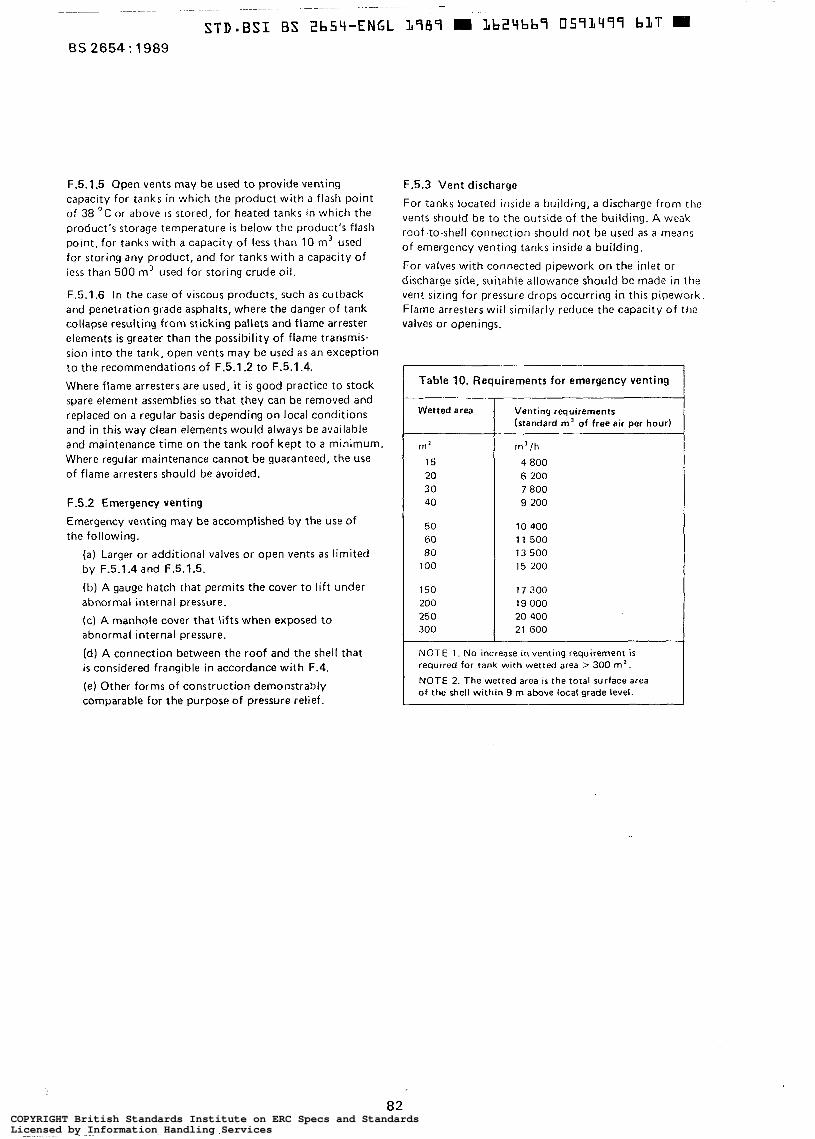
BS 2654: 1989
F.5.1.5 Open vents may be used to provide venting capacity for tanks in which the product with a flash point of 38 O C or above i s stored, for heated tanks in which the product’s storage temperature i s below the product‘s flash point, for tanks with a capacity of less than 10 m’ used for storing any product, and for tanks with a capacity of less than 500 m’ used for storing crude oil.
F.5.1.6 In the case of viscous products, such as cutback and penetration grade asphalts, where the danger o f tank collapse resulting from sticking pallets and flame arrester elements is greater than the possibility of flame transmis- sion into the tank, open vents may be used a s an exception to the recommendations of F.5.1.2 to F.5.1.4.
Where flame arresters are used, it i s good practice to stock spare element assemblies so that they can be removed and replaced on a regular basis depending on local conditions and in this way clean elements would always be available and maintenance time on the tank roof kept to a minimum. Where regular maintenance cannot be guaranteed, the use of flame arresters should be avoided.
F.5.2 Emergency venting
Emergency venting may be accomplished by the use of the following.
(a) Larger or additional valves or open vents as limited by F.5.1.4 and F.5.1.5.
(b) A gauge hatch that permits the cover to l i f t under abnormal internal pressure.
(c) A manhole cover that lifts when exposed to abnormal internal pressure.
(d) A connection between the roof and the shell that is considered frangible in accordance with F.4.
(e) Other forms of construction demonstrably comparable for the purpose of pressure relief.
F.5.3 Vent discharge
For tanks located inside a building, a discharge from the vents should be to the outside of the building. A weak roof-to-shell connection should not be used as a means of emergency venting tanks inside a building.
For valves with connected pipework on the inlet or discharge side, suitable allowance should b e made in the vent sizing for pressure drops occurring in this pipework. Flame arresters will similarly reduce the capacity o f the valves or openings.
Table 10. Requirements for emergency venting
Wetted area
m’
15 20 30 40
50 60 80
1 O0
150 200 250 300
Venting requirements (standard m’ of free air per hour)
m’/h
4 800 6 200 7 800 9 200
10 400 1 1 500 13 500 15 200
17 300 19 O00 20 400 21 600
NOTE 1. No increase in venting requirement is required for tank with wetted area > 300 m‘.
NOTE 2. The wetted area is the total surface area of the shell within 9 m above local grade level.
82 COPYRIGHT British Standards Institute on ERC Specs and StandardsLicensed by Information Handling ServicesCOPYRIGHT British Standards Institute on ERC Specs and StandardsLicensed by Information Handling Services
Appendix G. Seismic provisions for storage tanks
NOTE. Thls appendix gives recommendatlons for the seismic design of storage tanks and is based on the requirements of appendix E of API 650. The zone coefficients used in API 650 have been modified to lateral force coefficients expressed as a ratio of the acceleration due to gravity. This allows application of these calculations to geographical locations outside the USA,
It I S recognlzed that other procedures or additional requirements rnay be called for by the purchaser or the local authorities in highly active seismic areas. In this case, specialized local knowledge should be used in agreement between the purchaser, the local authority and the manufacturer which takes into account local requirements, the necessary integrity, soil conditions, etc.
Consideration should be given to design for an operating basts earthquake (OBEl condition and a safe shutdown earthquake (SSE) condition, when establishing site safety requirements.
The following definitions apply.
Operating Basis Earthquake (OSE) . The structure should resist this earthquake without any damage. It i s suggested to consider the seismic loads w i th a 10 % probability of being exceeded during the structure‘s lifetime. Allowable stresses should not be exceeded.
Safeshutdown Earthquake ISS€). The structure rnay be damaged by this earthquake, but it should not collapse nor should i t impose serious consequential hazards. It is suggested to use the seismic loads wi th a 1 % probability of being exceeded during the lifetime of the structures. Under this load the ultimate strength should not be exceeded.
G.l Design loading
G . l . l Overturning moment
The overturning moment due to seismic forces applied to the bottom of the tank shell should be calculated as follows:
GI ( T I X , + T, H, + TI X1 + G2 T2 X ,
102 M =
where
G1 is the lateral force coefficient given as a ratio of the
G2 is the lateral force coefficient given as a ratio of the
acceleration due to gravity (see G.1.3.1);
acceleration due to gravity and determined in accordance with G.1.3.2;
H L i s the total height of tank shell (in m);
M is the overturning moment applied to bottom of
T1 i s the weight of effective mass of tank contents
tank shell (in kN.m);
which moves in unison with tank shell and which i s determined in accordance with G.1.2.1 (in kg);
Tz is the weight of effective mass of the tank contents which move in the first sloshing mode and which is determined in accordance with G.1.2.1 (in kg);
T, i s the total weight of tank roof (fixed or floating) plus portion of snow load, if any, as specified by the purchaser (in kg);
Tt is the total weight of tank shell (in kg);
Xl is the height from bottom of tank shell to centroid of lateral seismic force applied to T , and which is determined in accordance with G.1.2.2 (in m);
X 2 i s the height from bottom of tank shell to centroid of lateral seismic force applied to T2 and which is determined in accordance with G.1.2.2 (in m);
X, is the height from bottom of tank shell to centre of gravity of shell (in m).
G.1.2 Effective mass of tank contents
G.1.2.1 The effective mass Tl and the effective mass T, (as defined in G.1.1). may be determined by multiplying T, by the ratios T, /TT and Tz/TT respectively. obtained from figure 43 for the ratio D/H,, where:
TT is the total weight of tank contents (based on a specific gravity not less than 1 .O) (in kg);
D is the diameter of tank (in m);
H, is the maximum filling height of tank from bottom of shell to top of curb angle or overflow which limits filling height (in m).
G.1.2.2 The heights from the bottom of the tank shell to the centroids of the lateral seismic forces applied to T , , T z , XI and X, may be determined by multiplying HT by the ratios X I I H T and X21HT, respectively, obtained from figure 44 for the ratio of DIHT.
G.1.2.3 The curves in figures 43 and 44 are based on a modification of the equations presented in E R D A Technical Information Document 7024.
G.1.3 Lateral force coefficients
G.1.3.1 The lateral force coefficient G I is to be specified by the purchaser on the basis of seismology records available for the proposed tank site and should be given as a ratio of the acceleration due to gravity.
For a storage tank constructed for service in the UK it is recommended that the lateral force coefficient G I be taken as no greater than 0.045.
83 COPYRIGHT British Standards Institute on ERC Specs and StandardsLicensed by Information Handling ServicesCOPYRIGHT British Standards Institute on ERC Specs and StandardsLicensed by Information Handling Services
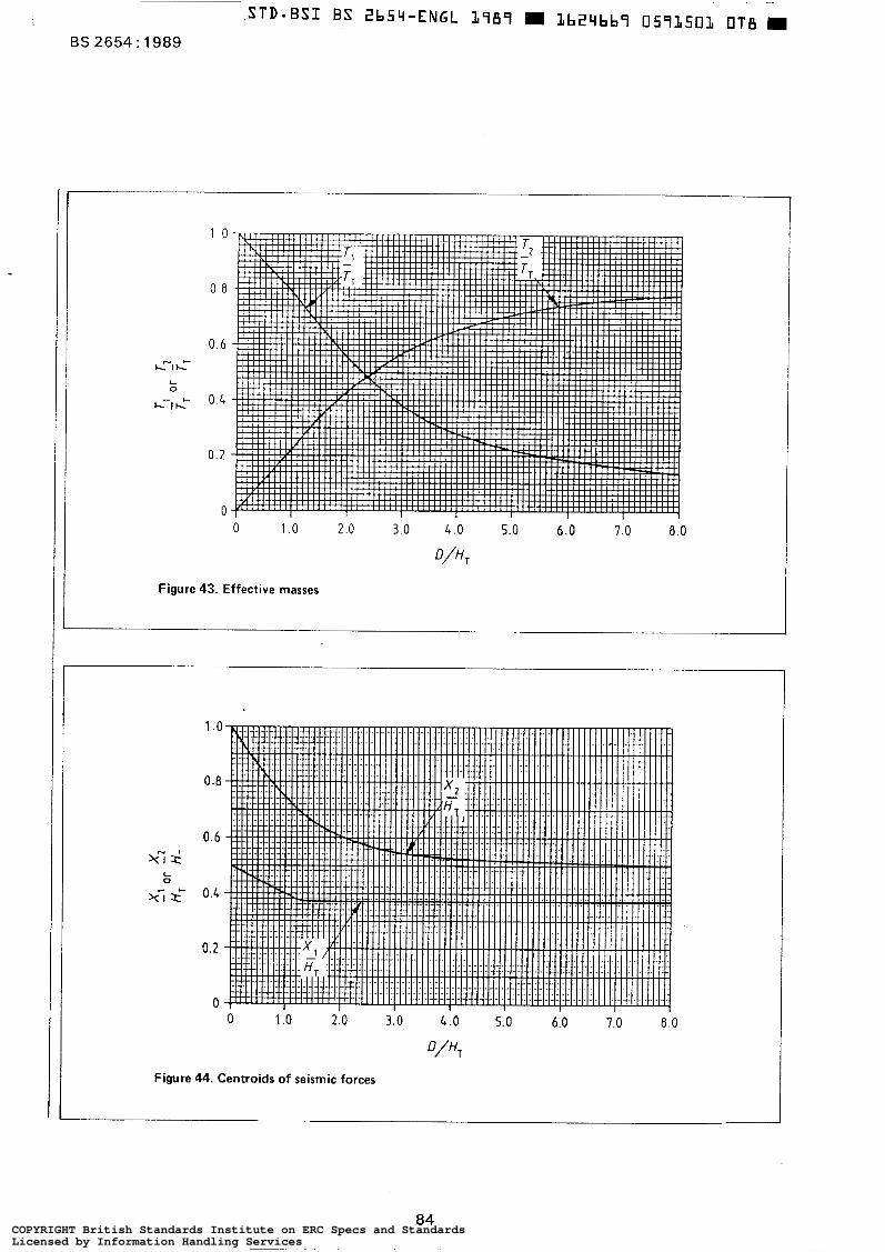
~~~~
BS 2654 : 1989
1 0
O .8
0.6
0.4
0.2
O O 1 .o 2 .o 3.0 4.0 5.0 6.0 7 0 8.0
D/HT
Figure 43. Effective masses
O 1 .o 2.0 3. O L.0 5.0 6.0 7.0 8.0
Figure 44. Centroids of seismic forces
84 COPYRIGHT British Standards Institute on ERC Specs and StandardsLicensed by Information Handling ServicesCOPYRIGHT British Standards Institute on ERC Specs and StandardsLicensed by Information Handling Services
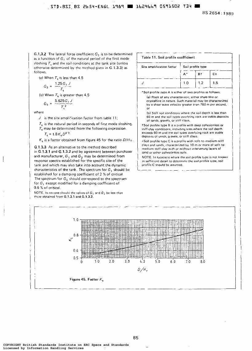
G.1.3.2 The lateral force coefficient G2 is to be determined as a funct ion o f G , o f the natural period of the f irst mode sloshing T5 and the soil conditions at the tank site (unless otherwise determined by the method given in G.1.3.3) as fol lows.
(a) When T, i s less than 4.5 1.25G1 J
G2 = T,
(b) When T, is greater than 4.5 5.625GL J
G2 = Ts2
where
J is the site ampli f icat ion factor from table 11;
T, i s the natural period in seconds of f i rst mode sloshing. T, rnay be determined from the following expression.
T, = 1.8 K, D' ' 2
K, is a factor obtained from figure 45 for the rat io DIHT.
G.1.3.3 As an alternative to the method described in G.1.3.1 and G.1.3.2 and by agreement between purchaser and manufacturer, G , and G, may be determined from response spectra established fo r the specific site of the tank and which may also take into account the dynamic characteristics of the tank. The spectrum for GI should be established for a damping coeff ic ient of 2 % of cr i t ical. The spectrum for G I should correspond to the spectrum for G , except modif ied for a damping coeff icient of 0.5 % of critical. NOTE. In no case should the values of GI and G2 be less than those obtained from G.1.3.1 and G.1.3.2.
1,-" Table 11. Soi l prof i le coeff ic ient
Site amplification factor Soil profile type
"Soil profile type A i s either of two profiles as follows. (a ) Rock of any characterlstlc. either shale-like or crystalline in nature. Such material rnay be characterized by a shear wave velocity greater than 760 m per second, or (b) St i f f soil conditions where the soil depth is less than 60 m and the soil types overlying rock are stable deposits of sands, gravels, or st i f f clays.
TSoil profile type B is a profile with deep cohesionless or s t i f f clay conditions, including sites where the soil depth exceeds 60 m and the soil types overlying rock are stable deposits of sands, gravels, or s t i f f clays. +Soil profile type C is a profile with soft-to-medium-stiff clays and sands, characterized by 10 m or more of soft-to- medium-stiff clay with or without intervening layers of sand or other cohesionless SOLIS.
NOTE. In locations where the soil profile t ype is not known in sufficient detail to determine the soil profile type, soil profile C should be assumed.
1 .a
0.8 kW
0.6
0.5
D/%
Figure 45. Factor K,
85 COPYRIGHT British Standards Institute on ERC Specs and StandardsLicensed by Information Handling ServicesCOPYRIGHT British Standards Institute on ERC Specs and StandardsLicensed by Information Handling Services
BS 2654: 1989
G.2 Resistance to overturning
G.2.1 The tank contents
Resistance to the overturning moment a t the bottom of the shell may be provided by the weight of the tank shell and by the anchorage of the tank shell or, for unanchored tanks, the weight of a portion of the tank contents adjacent to the shell. For unanchored tanks the portion of the contents which may be utilized to resist overturning is dependent on the width of the bottom plate under the shell which lifts off the foundation and may be determined as follows:
W L = 0.1 t b a v/ Reb Ws HT
except that wL should not exceed 0.2 W, HTD; and where
wL i s the maximum force of tank contents which may be utilized to resist the shell overturning moment ( in kN per metre of shell circumference);
r,, is the thickness of bottom plate under the shell
R,, is the minimum specified yield strength of bottom
W, is the maximum density of the contained liquid under storage conditions, to be not less than 1 .O (in g/ml).
(in mm);
plate under the shell (in N/mm2);
G.2.2 The thickness of the bottom plate
The thickness of the bottom plate under the shell, rba, should not exceed the thickness of the bottom shell course. Where the bottom plate under the shell is thicker than the remainder of the bottom, the width of the thicker plate under the shell in metres, measured radially inward from the shell, should be equal to or greater than:
WL
Ws H T 0.1744 -
NOTE. A narrower width of annular plate than that required by the above expression is acceptable provided the resultant reduced wL resistance loading is adopted in the shell compression compu- tations of G.3.
G.3 S hell compression
G.3.1 Unanchored tanks
G.3.1.1 The maximum longitudinal compression force a t the bottom of the shell, wb, may be determined as follows:
M
D’ ( w L + wt ) (a) when i s equal to or less than 0.785
1.273M W b = W, + ~
L I 2
(b) when M
D’ ( w L + wt) is greater than 0.785 but
less than or equal to 1.5, Wb may be computed from
the value of the parameter obtained from
figure 46
+ wL
wt + WL
where
Wb i s the maximum longitudinal shell compression force (in kN per metre of shell circumference);
wt is the maximum force exerted by tank shell and portion of roof supported by shell ( in kN per metre o f shell Circumference).
G.3.1.2 When M
D’ (wt + w L ) i s greater than 1.5, or when
wb/rb,exceeds Fa (when calculated using the method described in G.3.3). the tank is structurally unstable. In such cases, it is necessary to make the tank stable by one of the following methods:
(a) increase the thickness of the bottom plate under the shell, r,,, to increase wL, providing that the limitations of G.2.1 and G.2.2 are not exceeded;
(b) increase shell thickness, tbs;
(c) change the.proportions of the tank to increase the diameter and reduce the height;
(d) anchor the tank in accordance with G.4.
G.3.2 Anchored tanks
The maximum longitudinal compression force a t the bottom of the shell, W b (in kN/m), may be-determined as follows:
1.273M W b = W, + ~
O 2
86 COPYRIGHT British Standards Institute on ERC Specs and StandardsLicensed by Information Handling ServicesCOPYRIGHT British Standards Institute on ERC Specs and StandardsLicensed by Information Handling Services
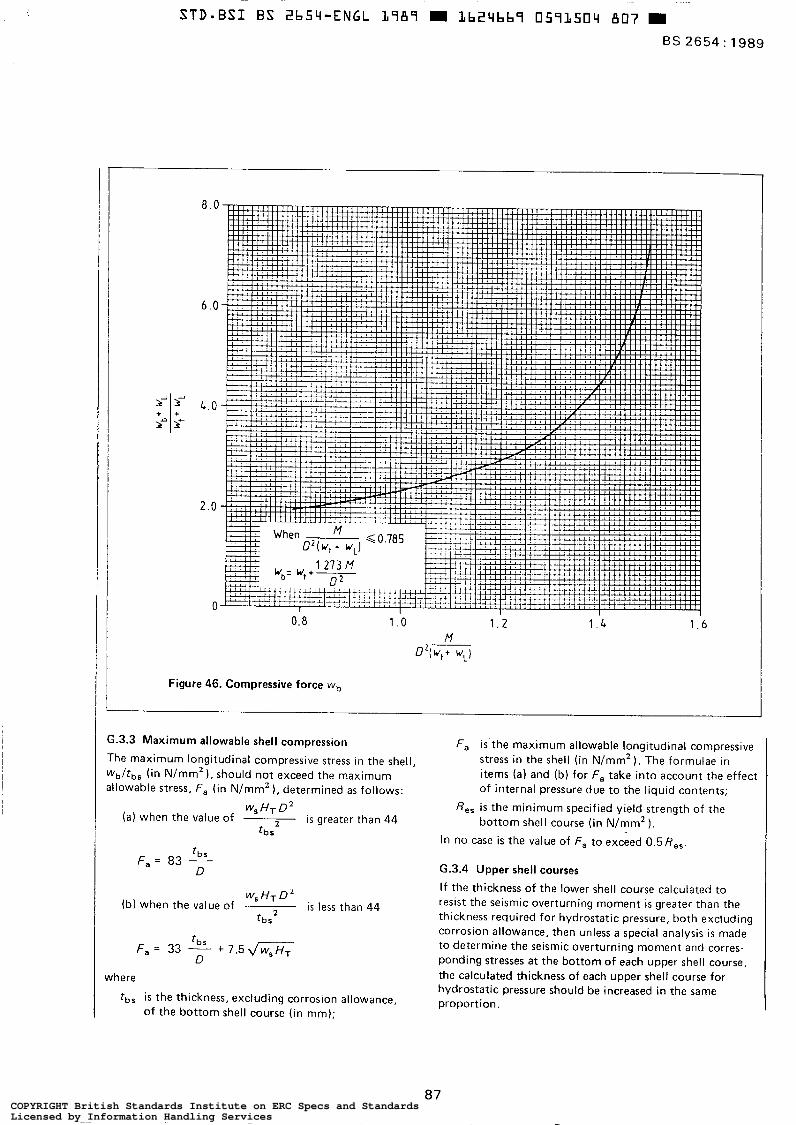
BS 2654: 1989
A- + f
1”
1- +
8 . 0
6 . 0
L. O
2.0
O O. 8 1 . 0 1 . 2
M WL)
1 . L 1 . 6
Figure 46. Compressive force wb
G.3.3 Maximum allowable shell compression
The maximum longitudinal compressive stress in the shell, W b / t b s (in N/mmz 1, should not exceed the maximum allowable stress, F, (in N/mmz), determined as follows:
(a ) when the value of ws HT O 2
is greater than 44 ‘bs
F, = 83 - ‘bs
O
F, = 33 - + 7 . 5 d x ‘bs
O
where
t b s is the thickness, excluding corrosion allowance, of the bottom shell course (in mm);
F, is the maximum allowable longitudinal compressive stress in the shell (in N/mm2 ). The formulae in items (a) and (b) for F, take into account the effect of internal pressure due to the liquid contents;
ß e , is the minimum specified yield strength of the bottom shell course (in N/mm2 ) ,
In no case is the value of F, to exceed 0.5ße,.
G.3.4 Upper shell courses
If the thickness of the lower shell course calculated to resist the seismic overturning moment is greater than the thickness required for hydrostatic pressure, both excluding corrosion allowance, then unless a special analysis is made to determine the seismic overturning moment and corres- ponding stresses a t the bottom of each upper shell course, the calculated thickness of each upper shell course for hydrostatic pressure should be increased in the same proportion.
87 COPYRIGHT British Standards Institute on ERC Specs and StandardsLicensed by Information Handling ServicesCOPYRIGHT British Standards Institute on ERC Specs and StandardsLicensed by Information Handling Services
BS 2654: 1989
(3.4 Anchorage of tanks
(3.4.1 Minimum anchorage required
When anchorage is considered necessary, i t i s to be designed to provide a minimum anchorage resistance ( in kN per metre of shell circumference) of:
1.273M ~-
D = Wt
The above anchorage resistance is in addition to that required to resist any internal design pressure on low and high pressure tanks. NOTE. Earthquake and wind loading should not be considered as acting concurrently.
G.4.2 Design of anchorage
G.4.2.1 If an anchored tank is not properly designed i ts shell can be susceptible to tearing. Care should be taken to ensure that the strength of anchorage attachments to the tank shell is greater than the specified minimum yield strength of the anchors so that the anchors yield before the attachments fail. Experience has shown that properly designed anchored tanks retain greater reserves of strength with respect to seismic overload than do unanchored tanks.
In addition to the requirements of 10.1 to 10.5, the recommendations given in G.4.2.2 to G.4.2.4 should be followed.
G.4.2.2 On tanks less than 15 m in diameter, the maximum spacing of the anchors should not exceed 2 m.
G.4.2.3 The allowable tensile stress in the anchorage due to the loadings given in item (a) of 10.1 together with the seismic loadings from G.4.1 should not exceed 1.33 times the stresses given in 10.3.
G.4.2.4 The attachment of the anchorage to the tank shell and the embedment of the anchor into the foundation should be designed for a load equal to the minimum specified yield strength of the anchorage material multi- plied by the as-built minimum cross-sectional area of the anchor. For the attachment of the anchorage to the tank shell and the embedment of the anchor into the foundation the design stress should not exceed 1.33 times that given in 7.1.1,
G.5 Piping
Suitable flexibility should be provided in the vertical direction for all piping attached to the shell or bottom of the tank. On unanchored tanks subject to bottom uplift, piping connected to the bottom should be free to l ift with the bottom or be located so that the distance measured from the shell to the edge of the connecting reinforcement is the width of the bottom plate (as calculated by G.2.2) pl us 0.3 m.
88 COPYRIGHT British Standards Institute on ERC Specs and StandardsLicensed by Information Handling ServicesCOPYRIGHT British Standards Institute on ERC Specs and StandardsLicensed by Information Handling Services
A
Publications refer4 to ES 131
ES 410 0s 449 ES 476
ES 882. 1201
ES 1470 ES 1503 ES 1806 ES 1560
BS 3792 ES 3958
ES 3971 BS 421 1 ES 4300/6
85 4741 I
ES 4866
Loading for buildings Part 2 Code of practice for wind loads
BS EN 287 Approval testing of welders for fusion welding Part i Steels
BS EN 288 Specification and approval of welding procedures for metallic materials Part 2 welding procedures specification for arc welding Part 3 Welding procedure tests for the arc welding of steels
Technical delivery condiions BS EN 10025 Hot r o l l e d produds of non-alloy StNchrf'al st-b - BS EN 10029 Tolerances on dimensions, shape and mass for hot rolled steel plates 3 mm thick or above 6s EN 10113 Hot rolled products in weldable fine grain structural steels
Part 1 General delively conditions Part 2 Delivery conditions for normaliiedhornaliied rolled steels
ff 110 The structural u m of comma CP 114 Structural use of reinforcd concrete in buildings CP 2004 Foundations I s 0 630 Structural e e l s ASTM A105 forgings, cmrbon nod. for pipitq components ASTM A106 Sumless carbon steel pipe for high tanpernure service ASTM A524 Scmlm carbon stad pipa for .tmo~heric 8M (ow teqmratura API S;mnbtd 5L Specififfion for line pipc
Mild seel for pressure e ~ ~ i p m a m ub-zom tanpantures. Brit& Wc#ing Jourru/. March 1964' R o r R.T. Rim reinforcement of manholes. Brit* Welding Joumrl. October 1961. N d u m a a o c ~ Md earthquakes. T d n i a l infannmri4n 7024 pmpared bv Lock- Aitct.ft Corpomm and Wmcr m d Nævu Inc. for the US Atomic Emrgv Commission. August 1963.
'AekrRd 10 in íoreword only.
8 BSI 1997
COPYRIGHT British Standards Institute on ERC Specs and StandardsLicensed by Information Handling ServicesCOPYRIGHT British Standards Institute on ERC Specs and StandardsLicensed by Information Handling Services
A Issue 2, January 1997 BS 2654 : 1989
This &itlh Spn6rd. &itg been prapuwd under me diration of the RsDIun V n r b &mchb PoIicv fhmmittem. Was Wlirhed Orders for all BSI, international and foreign standards
Buying standards
undrr th. uthorhy of th Soad of and con^ into effect on publications should be addressed to Customer Services, Sales 29 Sgtmber 1989 Department at Chiswick: Tel: 0181 996 7000; o &¡li* spndwdr Innitution, 1989 Fax: 0181 996 7001.
In response to orders for international standards, it is BSI policy ta supply the BSI implementation of those that have been published as British Standards, unless otherwise requested.
Information on standards BSI provides a wide range of information on national, European and international standards through its Library, the Standardline Database, the BSI Information Technoloav Service (BITS) and
Th. ref- *e to the work On standud: Department at Chiswick: Tel : 0181 996 71 1 1 ; its Technical Help to Exporters Service. ldontact the. Information
m nfrma WEI16 Dr& for 87177053 DC 0181 996 7048.
BSI is the independent national body responsible for preparing British Standards. It presents the UK review on standards in Europe and at the international level. It is incorporated by Royal Charter.
contract rsquitements A British Standard does not purport to include all the necessary provisions of a contract. Users of British Standards are responsible for their correct application.
U ~ o n s British Standards are updated by amendment or revision. Users of British standards should make sure that they possess the latest amendments or editions.
It is the constant aim of BSI to improve the quality of our products and services. We would be grateful if anyone finding an inaccuracy or ambiguity while using this British Standard would inform the Secretary of the responsible technical committee, the identity of which can be found on the inside front cover. Tel: 0181 996 9OOO; Fax: 0181 996 7400. BSI offers members an individual updating service called PLUS which ensures that subscribers automatically receive the latest editions of standards.
Subscribing members of BSI are kept up to date with standards developments and receive substantial discounts on the purchase price of standards. For details of these and other benefits contact Customer Services, Membership at Chiswick: Tel: 0181 996 7002; Fax: 0181 996 7001.
~ w r i s h t Copyright subsists in all BSI publications. BSI also holds the copyright, in the UK, of the publications of the international standardization bodies. Except as permitted under the Copyright, Designs and Patents Act 1988 no extract may be reproduced, stored in a retrieval system or transmitted in any form or by any means - electronic, photocopying, recording or otherwise - without prior written permission from BSI.
This does not preclude the free use, in the course of implementing the standard, of necessary details such as symbols, and size, type or grade designations. If these details are to be used for any other purpose than implementation then the prior written permission of BSI must be obtained.
If permission is granted, the terms may include royalty payments or a licensing agreement. Details and advice can be obtained from the Copyright Manager, BSI, 389 Chiswick High Road, London W4 4AL.
Amendments issued since publication
Amd. No.
Indicated in the margin by a sideline\ fJ\\3\Q> January 1997 9297
Text affected Date of issue
\.
British Standards Institution .389 Chiswick High Road London W4 4AL . Telephone 0181 996 9OOO . Fax 0181 9@ 7400
COPYRIGHT British Standards Institute on ERC Specs and StandardsLicensed by Information Handling ServicesCOPYRIGHT British Standards Institute on ERC Specs and StandardsLicensed by Information Handling Services
Amendment No. 1 published and effective from 16 January 1997 to BS 2664 ; 1989
Manufacture of vertical steel welded non-refrigerated storage tanks with butt-welded shells for the petroleum industry
Instructions for replacement of pages Where only one of the two pages on each sheet has been updated, the other page has been reprinted,
Front cover and inside front cover Replace the pages aandb 5and6 7 a n d 8 15 and 16 19 and 20 S a n d 5 6
Insert the pages immediately after the inside front cover Replace the pages Replace the pages Replace the pages Replace the pages Replace the pages
- 57 and 58 &place the pages - h i d e back cover and back cover Replace the pages I = - - I You may wish to retain the superseded pages, e.g. for reference purposes, if so please mark them ‘Supe&ed by
4 destxoy them.
_. issue X, where ‘X is the appropriate issue number. If you do not wish to retain the supexseded pages, please
m *
COPYRIGHT British Standards Institute on ERC Specs and StandardsLicensed by Information Handling ServicesCOPYRIGHT British Standards Institute on ERC Specs and StandardsLicensed by Information Handling Services
BRITISH STANDARD
Specification for
Manufacture of vertical steel welded non-refrigerated storage tanks with butt-welded shells for the petroleum industry
BS 2654 : 1989
Inco7pomting Amendment No. 1
NO COPYING WITHOUT BSI PERMISSION EXCEPT AS PEEMI'ITED BY COPYRIGHT LAW
COPYRIGHT British Standards Institute on ERC Specs and StandardsLicensed by Information Handling ServicesCOPYRIGHT British Standards Institute on ERC Specs and StandardsLicensed by Information Handling Services
STD-BSI B S 2b54-ENGL 2789 m Lb24bb7 0571520 O00
BS 2654 : 1989
Foreword
I This British Standard was prepared under the direction of the Pressure Vessel Standards Policy Committee and replaces BS 2654 : 1984 which is now withdrawn. It is designed to provide the petroleum industry with tanks of adequate safety, reasonable economy and in a range of suitable capacities for the storage of oil and oil products. The committee recognizes, however, that this standard could be adopted with equal safety and economy by other industries and/or for the storage of other products, although purchasers and manufacturers may need to formulate and agree additional requirements necessitated by the conditions pertaining to a particular application. NOTE. Users of this British Standard are reminded that the BSI committee responsible is prepared to offer interpretations of the text on request.
The requirements for material selection in th is standard have been based on the results of a number of notched and welded Wells Wide Plate Tests (WWP Tests) on carbon and carbodmanganese steel plates, carried out a t the Welding Institute. In particular, the proposals are related to the results reported in 'Mild steel for pressure equipment sub- zero temperatures', British Welding Journal, March 1964, but al l other known W P test data have been taken into account. They also reflect many subjective assessments of practice to date in this field as permitted by current British, American and German codes.
WWP test data all indicate that resistance to brittle fracture is dependent upon the following.
(a) Notch toughness of the material.
(b) Plate thickness.
(c) Extent of crack-like defects present; it is believed that i f such defects are absent, brittle fracture will not be a problem at normal rates of loading.
(d) Degree of local embrittlement at t ip of pre-existing defects; in the case of carbon and carbonlmanganese steels, post-weid heat treatment in the stress relieving range temperature is effective in removing Severe embrittlement arising as a result of welding and/or flame cutting operations.
The method specified is for determining the notch tough- ness required of a material in any given thickness for design temperatures down to - 10 'C based on tests in which through-thickness defects up to 10 mm long, located both in locally embrittled and post-weld heat treated material, are required to withstand approximately four times yield point strain (see figure 1).
Scale A is derived using these criteria and data from WWP tests for as-welded joints. Scale B is used for determining the requirements for the hydrostatic test.
Appendix A gives recommendations for tank foundations and appendix B gives recornmendations for the design and application of insulation.
This standard is expressed in metric units and a proposed range of standard metric diameters and capacities is given in appendix C.
All pressure and vacuum values in this standard are expressed as gauge values.
The symbols used throughout the t e x t are as listed in appendix D. Appendix E gives recommendations for internal floating covers, appendix F gives recommendations for the design of venting systems and appendix G offers seismic loading I provisions.
It has been assumed in the drafting of this British Standard that the execution of i t s provisions is entrusted to appro- priately qualified and experienced people.
This edition introduces technical changes to bring the standard up-to-date but it does not reflect a full review of the standard, which will be undertaken in due course.
Cornpliam with a British Standard dom not of itself confer immunity from legal obligations.
COPYRIGHT British Standards Institute on ERC Specs and StandardsLicensed by Information Handling ServicesCOPYRIGHT British Standards Institute on ERC Specs and StandardsLicensed by Information Handling Services
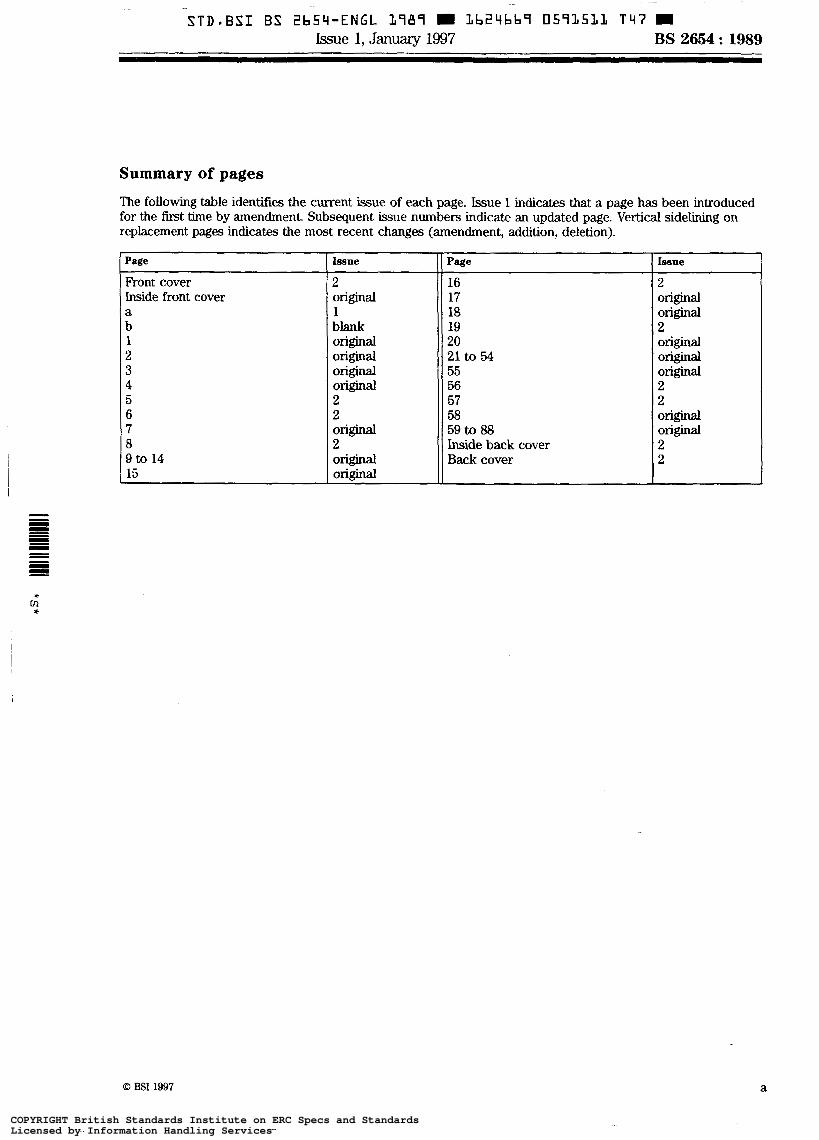
STD*BSI BS ZbS' i -ENGL L787 3b24bbS 0593533 T 4 7 W b e 1, January 1997 BS 2654 : 1989
Summary of pages
The following table identifies the current issue of each page. Issue 1 indicates that a page has been introduced for the first time by amendment. Subsequent issue numbers indicate an updated page. Vertical sidelining on replacement pages indicates the most recent changes (amendment, addition, deletion).
Psge
Front cover Inside front cover a b 1 2 3 4 5 6 7 8 9 to 14 15
Issue Issue Page
2 O r i g i n a l
2 16
O r i g i n a l 18 1 O r i g i n a l 17
O r i g i n a l 20 O r i g i n a l O r i g i n a l 21 to 54
Orig ina l 59 to 88 O r i g i n a l O r i g l M l 58 2 2 57 2 2 56 Original original 55 O r i g i n a l O r i g i n a l
2 Inside back cover 2 Original Back cover 2 O r i g i n a l
blank 2 19
a
COPYRIGHT British Standards Institute on ERC Specs and StandardsLicensed by Information Handling ServicesCOPYRIGHT British Standards Institute on ERC Specs and StandardsLicensed by Information Handling Services
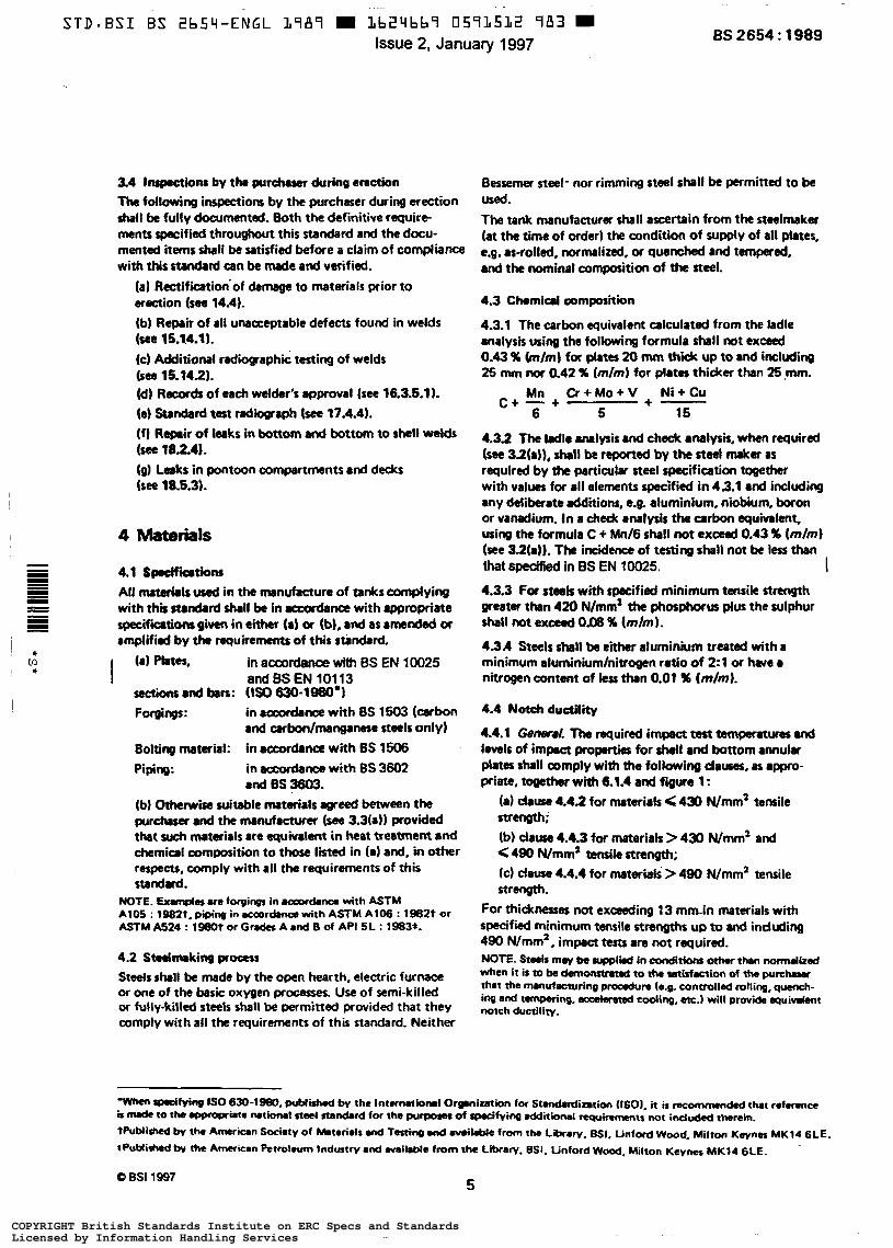
~- ~
STD-BSI BS 2654-ENGL L787 H 1b2'4bbS 0591512 9 8 3 m Issue 2, January 1997 BS 2654 : 1989
3.4 Inspections by the prrdruer during enction The following inspections by the purchaser during erection s h a l l be fully doarmentsd. Both the definitive require- ments specified throughout this standard and the docu- mentd items shal l be satisfied before a claim of compliance with this standard can be macle and verified.
(a) Rectifkation~of damage to materials prior to araaion (see 14.4). (b) Repair of all unacceptable defects found in welds (see 15.14.11. (c) Additional radioqaphic testing of welds bee 15.1491. (d) Racads of each welder's approval (see 16.3.6.11. 48) Standard test radiograph lsee 17.4.4). (fl Repair of leaks in bottom and bottom to shell welds (see 182.41. (0) Leaks in pontoon compartments and decks (see 18.531.
Materials
4.1 Spdfiadons All mrtarir ls used in the manufacture of t a n k s complying with thb standard shall be in accordance with appropriate specircoltions given in either {a) or (b), and as amended or amplified by the requirements of th is stindad.
* m * I in accordance with BS EN 10025
and BS EN 10113
Forgings: in a & m with 8s 1503 (cerbon
Bolting material: in accocdlnce with ES 1506
sections and ban: (Is0 630-1980*1
and urbonlmanganese steels only)
Piping: in atxordrnes with 8s 3602 and 0s 3603.
(b) Otherwise suitable mrterials agreed between the purchaser and the manufacturer (see 3.3(a)) provided that such mrterials are equivalent in heat treatment and chemical composition to those l i in (al and. in other respects, cornply with all the requirements of this standud.
NOTE. Examples ara foqings in aQMd.nce with ASTM A l 0 5 : W82t. piping in wardatuæ with ASTM A l 0 6 : 1962t or ASTM A524 : 1980t or G n d c s A and B of API 5L : 1983%
4.2 Stadmaking procm Steels shall be made by the open hearth, electric furnaa? or one of the bmsic oxygen processes. Use of semi-killed or fully-killed steels shall be permitted provided that they comply with all the requirements of this standard. Neither
Bessemer steel- nor rimming steel shall be permitted to be used. The tank manufacturer shal l ascertain from the steelmaker (at the time of order1 the condition of supply of all ptates, e.g. as-rolled, normalized, or quenched and tempered, and the nominal composition of the steel.
4.3 Chemical oomposition
4.3.1 The carbon equivalent calculated from the ladle analysis using the following formula shall not exceed
25 mm nor 0.42 % ( m h ) for plates thicker than 25 mm. 0.43 % ( d m ) f a flat= 20 IlMn t h ¡ Up to 8 d iflduding
Mn Cr+Mo+V + Ni+Cu 6 5 15
c + - +
4.3.2 The kdle analysis and check analysis, when required (see 32(a)), shall be reported by the steel maker as required by the partiarlar steel rpecificatiorr together with values for all elements Ipecified in 43.1 and including any delibarate addiiions, t.8. aluminium. niobium, boron or vanadium. In a check analysis the a r h equivalent. using the formula C + Mnl6 shall not exceed 0.43 9b (rnlml (see 32(a)). The incidence of testing shall not be l e s s than that specified in BS EN 10025. I 4.3.3 For steels with specified minimum tmsik strength greater than 420 N/mm2 tht phosphorus plus the sulphur shall not exceed 0.08 % (m/m 1. 4.3 A Steels shell be aluminium treated with a minimum aluminiumlnitrogcn ratio of 2:l or haue nitrogen content of kss than 0.01 % (m/m).
4.4 Notch ductility
4.4.1 Genanl. The required impact test temperatures uuJ levels of impact properties for shell a d bottom annular plates shall comply wim the following d a w s , as appro- priate, toaether with 6.1.4 and figure 1 :
(a) dause 4.42 for materials < 430 Wmm2 tensile strength; (b) dause 4.4.3 for materials > 430 Wmm' and G 490 Wmm' tensila strength; (C) dause 4.4.4 for materials > 480 Wmm2 tensile strength.
For thicknerm not excseding 13 mrnh matcriais with specified minimum tensile strengths up to and induding 490 Wrnm', impact tests are not required. NOTE. S-b my be suppt¡¡ In conditions othn thrn nomdked when it is to be damonstraw to the utkfœtion of pu=- that the nunufaauring proadun (e.% controlled rolling, q w h -
notch ductility. and tmparing. auxbmad coding, m.) wilt prov'a e q u i ~ n t
COPYRIGHT British Standards Institute on ERC Specs and StandardsLicensed by Information Handling ServicesCOPYRIGHT British Standards Institute on ERC Specs and StandardsLicensed by Information Handling Services

4.4.2 Mater&& with speciftèd minimum tmsi7e strengths less t h a r or equal to 430 Nlmm’ , thicker than 13 mm. Materials with specified minimum tensile strengths less than or equal to 430 Nlmm’ and thicker than 13 mm shall be impact tested and show not less than 27 J Charpy V at +m ”C or at the test temperature indicated in figure 1, whichever is the lower. Three specimens shall be tested, the value taken being the minimum average of the three results. The minimum individual value shall be not less than 70 %of the specified minimum average value. NOTE. Provided the design maul ~ c ~ r o t u r e is +1O0C or obove. it h not necessary to test motrials with a specified minimum yield str.ngth M( exceeding 300 Nlmn’ and less than 20 mm thick.
4.4.3 Materivis with specified minimum tensile strengths qrsater than 430 N/mm’ and up to end including 490 Nlmm’, thicker than 13 mm. Materials with specified minimum tensile strengths greater than 430 N/mm2 and up to and induding 490 Nlmm’ and thicker than 13 mm shall be impact tested and show not less than 41 J Charpy V at - 5 ‘C or 8t the test temperature indicated in figure 1, whichever is the lower. Three specimens shall be tested, the value taken being the minimum average of the three results The minimum individual value shall be not less than 70 % of the specified minimum average value.
4.4.4 Materials with wedried minimum tensile strengths grQst8r than 490 N/mm’, all thicknesses. Materials with specified minimum tensile strengths greater than 490 N/mm2 and of all thidmeses shall be impact tested and show not less than 41 J Charpy V at - 15 ‘C or at the test temperature indicated in figure 1, whichever is the lower. Three speci- mens shalt be tested, the value taken being the minimum avenge of the three results. The minimum individual value shall be not less than 70 % of the specified minimurn average value.
4.5 Mountings
4.5.1 Reinforcing plates and insert plates shall have a minimum specified yield strength not less than 90 ’% of the
minimum specified yield strength for the shell plates to which they are attached. Nozzle bodies shall also comply wi th these requirements when the nozzle body is used in the reinforcement calculation.
4.5.2 Permanent attachments, reinforcing plates, insert plates, nozzle bodies and flanges shall camply with the notch ductility requirements of 4.4. The reference thickness shall be taken as the nominal thickness of the component except for the following.
(a) Welding neck flanges. The reference thickness shall be taken as the thickness at the weld or 25 % of the flange thickness, whichever is greater.
(b) Hubbed or slipon /langes. The reference thickness shall be taken as the nominal thickness of the branch to which the flange is welded or 25 %of the flange thickness, whichever is greater. (c) Reinforcing plates. The reference thickness shall be taken as i ts nominal thickness and if such plates exceed 40 mm thick, they shall show not less than 27 J Charpy V at -50 ‘C, irrespective of the minimum design metal temperature. Three specimens shall be tested, the value taken being the minimum average of the three results. The minimum individual value shall be not less than 70 % of the specified minimum average value.
4.6 Other requirements
4.6.1 The measured thickness at any point more than 15 mm from the edge of any shell (whore thickness shall compfy with 7-1-31, bottom, roof ar annular plate shall not be less than the specified thickness less half the total tolerance given in table of BS EN 10029, dass O. 4.6.2 The measured thickness at any point more than 15 mm from the edge of shell plates whose thicknesses have been calculated in accordance with 7.22 to be greater than as specified in 7.1.3. shall not be l e s than the cdlculated minimum thickness, ¡.e. table 1 of BS EN 10029, dass C. I
I
O B S I 1997
6 COPYRIGHT British Standards Institute on ERC Specs and StandardsLicensed by Information Handling ServicesCOPYRIGHT British Standards Institute on ERC Specs and StandardsLicensed by Information Handling Services
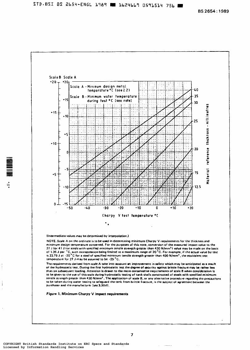
STD-BSI BS 2b54-ENGL 1787 LbZqbb9 0571514 75b 9 BS 2654 : 1989
Scale B Scale A
-50 -G O -30 -20 -10 O + 10 + 20
Charpy V test temperature " C
(Intermediate values may be determined by interpolation.)
NOTE. Scale A o n the ordinate i s to be used in determining minimum Charpy V requirements for the thickness and minimum design temperature concerned. For the purposes of this note, conversion of the measured impact value to the 27 J lor 4 1 J lor steels w i th specified minimum tensile strength greater than 430 Nlmm') value may b e made on the basis of 1.35 J per "C. such extrapolation being limited to a maximum range of 20 ' C . For example. if the actual value by test is 33.75 J at -20 OC for a steel of specified minimum tensile strength greater than 400 Nlmm'. the equi-ialent test temperature for 27 J may be assumed to be -25 OC. l h e requirements derived from scale A take into acmunt an improvement in safety which may ba anticipated as a result of the hydrostatic test. During the first hydrostatic test the degree o f security against brittle fracture may be rather l e s s than o n subsequent loading. Attention is drawn to the more conservative requirements of scale B when consideration is to be given to the use of this scale during hvdroztatic testing of tank shells constructed o f steels with specified minimum tensile strength greater than 430 Nlmm' . The application of scale B, or any alternative procedure regarding the precautions to be taken during water testing to safeguard the tank from brittle fracture. is the subject of agreement between the purchaser and the manufacturer (see 3.3(b)).
Figure 1, Minimum Charpy V impact requirements
7
J
COPYRIGHT British Standards Institute on ERC Specs and StandardsLicensed by Information Handling ServicesCOPYRIGHT British Standards Institute on ERC Specs and StandardsLicensed by Information Handling Services
BS 2654 : 1989
5 Design loadings
5.1 General The tank shall be designed for the most severe possible combination of the loadings specified in 5.2 to 5.7.
5.2 Dud loads Oead loads shall be considered as those resulting from the weight of all component parts of the tank.
5.3 Superimpord l o r d s
5.3.1 l h e fixed roof and supporting structures shall be designed to support a minimum superimposed load of 1.2 kN/m’ of projected area. The superimposed load shall be the sum of either internal vacuum and snow load, or internat vacuum and live load.
5.3.2 Unless otherwise specified by the purchaser (see 3.2(bll, the weight of any insulation shall be included in the minimum superimposed loadings for fixed roofs specified in 5.3.1.
5.3.3 The superimposed loadings applied to floating roofs shall be as specified in clause 9.
5.4 Contents The losd due to the Contents shall be the weight of the product to be stored from full to empty, with or without the specified vapour pressure. For the design of the shell, the product relative density shall be assumed to be not kss than 1.0.
5.5 Lords resulting from connected piping
Pipes, valves and other items connected to the tank shell shall be designed in such a manner that no significant additional loads or moments are applied to the tank shell.
Settlement of all pipe support foundations relative to those of the tank, rotational and translational movements of the lowest shell course shall be taken into consideration. The purdrasa shall state whether this loading is significant (see 321~)). otherwise it shall not be taken into account.
5.6 Wind W i n g
The wind speed used in the calculations shall be the maximum three second gust speed estimated to be exceeded on the merage only once in 50 years.
In the UK this value shall be taken as effedive ’wind speed’ as defined in 6s 6399 : Part 2. In other areas the I
three second gust s p e e d shall be obtained from the appro- priate authority. NOTE. Careful consideration should be giwn 10 open-top v w e r tanks without any form of roof s i n a wind effects could produce Kvere movement of the contents resulting in spi l l~e and ex ces sr^ loading on the tank. If this l o a d i n g onnot be quantified, ir ir recommended that a roof be provided unless proviaus experience with similar conditions has proved satisfactory.
5.7 Seismic Iods (if applicable) The purchaser shall specify whether the tank is to be designed to withstand seismic loads (see 32(d)). NOTE. Recommendations on seismic provisions for storage tanks art
6
6.
6.
given in appendix G.
Bottom design
1 General
.1 Full support of the tank bottom by the foundation 1. shall be assumed. NOTE. fbmmmcndationr for tank foundations and typical lank cmds are given in appendix A.
6.1.2 Bottoms for tanks up to and including 12.5 m diameter shall normally be constructed from rectangular plates, with sketch plates to the perimeter. In particular cases, by agreement between the purchaser and the manu- facturer (see 3.3(c)). a ring of annular plates or other layouts are permitted. The specified thickness of the rectangular, sketch and annular plates shall ba not less than 6 mm (see 4.6.1), excluding the corrosion d ~ ~ n ~ . I 6.1.3 All tanks greater than 12.5 m diameter shall have a ring of annular plates having the following minimum thicknesses:
(a) 8 mm, when the bottom course of shell plating is 19 mm thick or less: (b) 10 mm, when the bottom course of shell plating is over 19 mm up to and including 32 mm thick;
(c) 12.5 mm. when the bottom courSe of shell plating is over 32 mm thick.
The specified thickness of both the rectangular plates and the sketch plates shall be not less than 6 mm (see 4.6.1). All thicknesses excluding the corrosion allowance. I 6.1.4 The annular Plates shall have a minimum width of 500 mm and shall be of the same material specification with respect to strength and impact requirements as the bottom course of shell plate.
6.1.5 The minimum distance from the outer surface of the shell Plates to the outer edge of the bottom plates shall be in accordance with sections 0-0 and E- E of figure 2.
8 Q BSI 1997
COPYRIGHT British Standards Institute on ERC Specs and StandardsLicensed by Information Handling ServicesCOPYRIGHT British Standards Institute on ERC Specs and StandardsLicensed by Information Handling Services
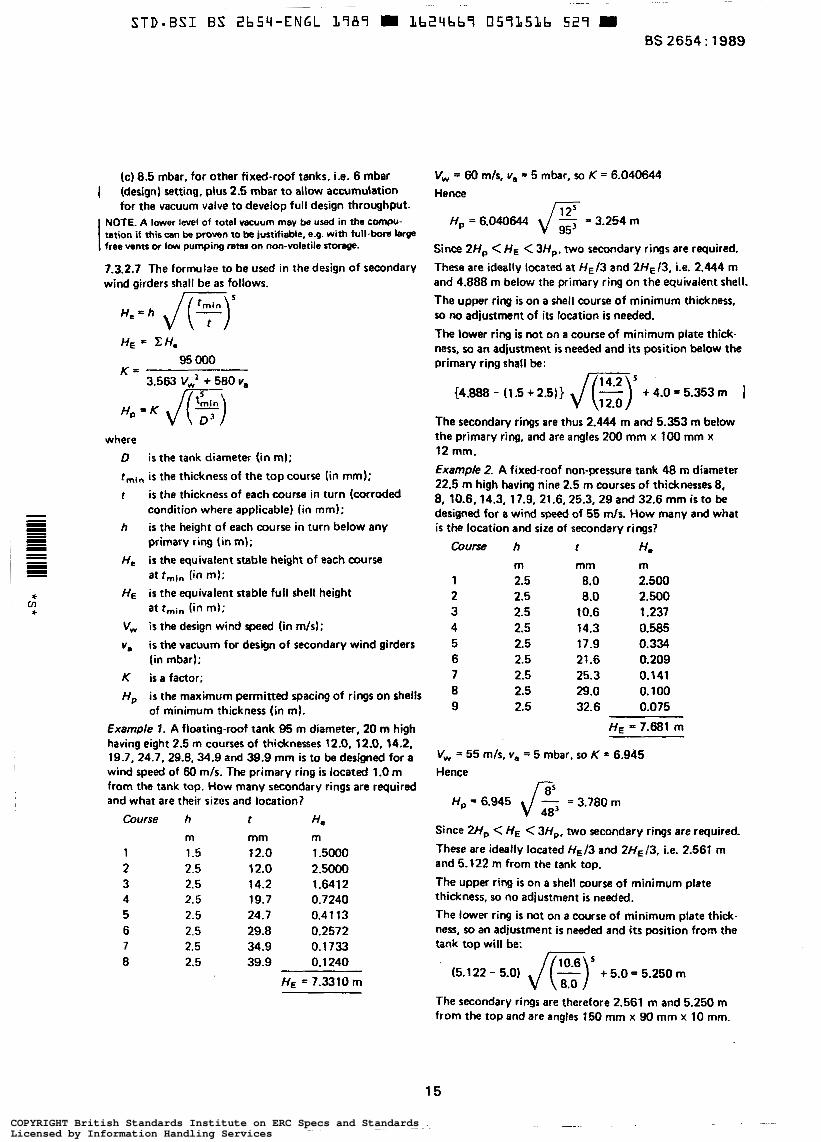
(c) 8.5 mbar. for other fixed-roof tanks, ¡,e. 6 mbar
for the vacuum valve to develop full design throughput. I (design) setting, plus 2.5 mbar to allow accumulation
I NOTE. A lower level of total vacuum may be used in the compu- tation if this can be proven to be justifiable, e.g. with full-bore large free vents or low pumping raw on non-voletile storege.
7.3.2.7 The formulae to be used in the design of secondary wind girders shatl be as follows.
H , = h ,/(F)’ K =
H, = K JE) 3.563 V,’ + 580 v,
where D i s the tank diameter (in m);
rmin is the thickness of the top course (in mm);
t is the thickness of each course in turn (corroded
h i s the height of each course in turn below any - condition where applicable) (in mm);
= primary ring (in m); _. H, is the equivalent stable height of each course B at rmln (in m);
rc HE is the equivalent stable full shell height * at rmin (in m);
I =
CI]
V, is the design wind speed (in mis);
v, is the vacuum for design of secondary wind girders (in mbar);
K is a factor; H, i s the maximum permitted spacing of rings on shells
of minimum thickness (in m). Example 1. A floating-roof tank 95 m diameter, 20 m high having eight 2.5 m courses of thicknesses 12.0, 12.0,14.2, 19 -7, 24.7, 29.8,34.9 and 39.9 mm is to be designed for a wind speed of 60 mis. The primary ring is located 1.0 m from the tank top. How many secondary rings are required and what are their sizcs and location?
Course h r He m
1 1.5 2 2.5 3 2.5 4 2.5 5 2.5 6 2.5 7 2.5 8 2.5
mm m 12.0 1.5000 12.0 2.5000 14.2 1.6412 19.7 0.7240 24.7 0.41 13 29.8 0.2572 34.9 0.1733 39.9 0.1 240
HE = 7.3310 m
V,,, = 60 m/s, v, = 5 mbar, 50 K = 6.040644 Hence
H, = 6.040644 = 3.254 m
Since ZH, < H E < 3H,. two secondary rings are required.
These are ideally located at HE/3 and 2H~13, ¡.e. 2.444 m and 4.888 m below the primary ring on the equivalent shell. The upper ring is on a shell course of minimum thickness, so no adjustment of its location is needed.
The lower ring is not on a course of minimum plate thick- ness, M an adjustment is needed and i t s position below the primary ring shall be:
c4.888 - (1.5 + 2.5)) ,/E) + 4.0 = 5.353 m 1 The secondary rings are thus 2.444 m and 5.353 m below the primary ring, and are angles 200 mm x 1 0 0 mm x 12 mm.
Example 2. A fixed-roof non-pressure tank 48 m diameter 22.5 m high having nine 2.5 m courses of thicknesses 8, 8, 10.6,14.3, 17.9, 21.6, 25.3, 29 and 32.6 mm is to be designed for a wind speed of 55 m/s. How many and what is the location and size of secondary rings?
course h t He m 2.5 2.5 2.5 2.5 2.5 2.5 2.5 2.5 2.5
mm 8.0 8.0
10.6 14.3 17.9 21.6 25.3 29.0 32.6
m 2.500 2.500 1.237 0.585 O. 334 0.209 0.1 41 o. 1 O0 0.075
HE = 7.681 m
V, = 55 mis, v, = 5 mbar. 50 K = 6.945 Hence
Since 2Hp <HE < 3H,, two secondary rings are required.
These are ideally located 413 and 2HE/3, ¡.e. 2.561 m and 5.122 m from the tank top.
The upper ring is on a shell course of minimum plate thickness, so no adjustment i s needed.
The lower ring is not on a course of minimum plate thidc- ness, so an adjustment is needed and i t s position from the tank top will be:
The secondary rings are therefore 2.561 m and 5.250 m from the top and are angles 150 mm x 90 mm x 10 mm.
15
COPYRIGHT British Standards Institute on ERC Specs and StandardsLicensed by Information Handling ServicesCOPYRIGHT British Standards Institute on ERC Specs and StandardsLicensed by Information Handling Services
BS 2654 : 1989
sina the top stiffener comes within 150 mm of a hori- mnîai seam, it has to be moved. Whether i t is moved up say 21 1 mm to 2.35 m or down say 89 mm to 2.65 m from the tank top, the three portions of the tank are still stable against the design conditions as the positions resulting from moving the upper stiffener either up or down still gives a distance between the stiffeners l e s than H,, (= 3.78 m).
7.8 Shall phte arrangement The tank shall be designed to have all courses truly vertical. NOTE. It ir raonmended th8t the distancc between vertical joints in .dirent courses should not be less than one-third of the plate length. When this d iaana is l e s than one-third of the plate length. rdditiocul p n u u t i o ~ MV be necessary to prevent undue dinonion.
7.5 Shell joints
7.5.1 All vertical seams shall be butt joints and shall have full penetration and complete fusion.
7.5.2 All horizontal seams shall be butt joints and, for a distance of 150 mm at either side of each vertical seam (T-junctions), shall have full penetration and complete fusion. The procedure used for welding portions of the girth seams between the T-junctions shall be that approved (see clause 16). NOTE. It is reagnitd that. in practia, ant inuow full penetra- t k n my not k uhicvrd between T-junctions. This need nol marorih k UI# for rejecfian. prwidd th8t the k k of futf puwtmtion u inurminmt. longitudinal in -un Md doet not u d rpprox*nnelv 10 X of the thickMa of the thicker plate pid. Some dimretion h rce~mmmdsd a g a i n s t rigorous rectification of k k of panatmfion. since repair w e l d s may introduce possible
greater t h the original defect.
8.1 Lords Roofs shall be designed to support the loads specified in d u e 5.
8.2 Type of roof
8.21 One of the two following types of roof shall be specified:
(a) the self-supporting cone or dome roof; or
(b) the column-supported roof. NOlE.CoIwnn-suwoncd roofs are not rrconwnended to be used on founbtiom where significant settlement is anticipated unless m l desiin pmvbions are made.
8.22 The roof slope of a cone roof shall either comply with the requirements specified by the purchaser (see 32(e)(l)) W be 1 in 5. Where a darned roof is adopted, the radius of armature shall either comply with the requirements specified by
the pwchaser (ses 3.2(e)(2)) or be 1.5 times the diameter of the tank. NOTE. Normally the radius of amature l i e s within the range 0.8 to 1.5 times the diameter of the tank.
Where a column-rupported roof ir usmd, 4 slope of 1 in 16 ir recommended.
8.3 Roof plating with supporting strudure
8.3.1 Roof-supporting structures (cone. dome or column supported) shall be designed in accordance with BS 449. The spacing of roof-plate-supporting members for cone roofs shall be wch that the span between them does not exceed 2.00 m where one edge of the panel is supported by the top curb of the tank. Where this support i s not present, the span shall not exceed 1.7 m. For dome roofs, this spacing shall be permitted to be increased as agreed between purchaser and manufacturer (see 3.3(d)).
8.3.2 Roof plates shall be continuously fillet welded to the top curb angle. For tanks exceeding 12.5 m diameter, roof plates shall not be attached to the roof-supporting structure.
8 3 3 The specified thickness of all roof plating shall be not less than 5 mm (see 4.6.1), exduding the corrosion allowance. I 8.3.4 The steel used for construction of the roof members shall have a specified thickness of not less than 5 mm, exduding the corrosion allowanœ. I NOTE. This does not mpply to the *of rolled nod joists and channels or packingr or to structures in which m i a l provisions .g.inrt corrosion we made.
8.3.5 Unless otherwise specified by the purchaser (see 32(e)(3)), plates shall be lapped and continuously fillet welded on the wtside with a minimum lap of 25 mm. NOTE. They should be lapped LO th81 the lowr edge of the uPPer- most plnc is k m t h the u m r of the bwrr pWe in &r to minimize the possibility of condensate moisture entering the I m p joint. Depending on the t8nk concenntr. it may somethes be necasury for the Irp joint to be double-weldd (W mde 8s a butt joint.
8.3.6 The joint efficiency shall be taken as 1 .O for butt welds, 0.35 for lapped joints with fillet welds on one side only and 0.5 for lapped joints with fillet.welds on both sides. The allowable stress shall be taken as two-thirds of the yield strength. Increases in joint efficiency for a lap welded roof plate shall be permitted by agreement between the purchaser and the manufaaurer (see 3.3{e)), provided that this can be justified by special procedure tests simulating the actual configuration to be used on site.
8.3.7 All roof framing shall be provided with bracing in the plane of the roof surface complying with the following.
(a) Cross bracing in the plane of the roof surface shall be provided in at least two bays, ¡.e. between two pairs of adjacent rafters, on ail roofs exceeding 15 m diameter. Sets of braced bays shall be spaced evenly around the tank circumference.
16 O BSI 1997
COPYRIGHT British Standards Institute on ERC Specs and StandardsLicensed by Information Handling ServicesCOPYRIGHT British Standards Institute on ERC Specs and StandardsLicensed by Information Handling Services
STD-BSI BS ZbSq-ENGL 1787 l b 2 q b b 7 U5715LB 3TL Bs2654:1989
Issue 2, January 1997
(b) a doubledeck root t u s both an upper and a lower deck extending over the area of the liquid suUrfiCC, the lower deck in contact with the liquid surface being separated from the upper deck by rim pfates and bulk- M plates to form lquid-tight pontoon compartments.
In normal operation. the roof shall remain in the floating condition and shall only be landed on to its support leor for maintenance or inspection purposes. The purchaser shall specify whather the floating roof is to be designed to hnd as part of the normal operating proadure (see 32(f)(1)), otherwise this requirement does not apply.
9.1.2 The roof and accessories shall be so designed and constructed as to allow the tank to overflow a d than return to 8 liquid level which floats the roof well below the top of the tank shel l without damage to any part of the roof, tank or a p p u r t e n a n c e s . This requirement shall apply under both service and hydrostatic testing ConditionS.
If a windskirt or top-shell extension ir used for the purpose of containing the roof seals at t h highest point of travel, overflow drainage openings shall &e provided to indicate the rise of the liquid level in the tank above the designed capaci*/ height,. unless the tank she l l has been designed for a l i q u i d height to the top of the shell extension.
9.13 The specified thickness of all roof plating shall be not krs than 5 mm (see 4.6.1). NOTE. A corrosion allowanœ is not normally specified for floating roofs but if it is, the design should be checked in both corroded and unawoded conditions.
9.2 Design nquinrnentr
9.2.1 Buoyancy
921.1 Genenl. The roof shall comply with 92.1.2.9.2.1.3 or 92.1 A, as appropriate.
9.212 SingMtxk pornoon rvofs. lhe design of single- deck pontoon roofs shall comply with the following.
(a) The minimum pontoon volume of a singledeck pontoon roof shall besufficient to keep the roof f h t - ing on a liquid with 8 relative density not e x d i n g 0.7 if the single deck and any two pontoon compartments we punctured .nd the primary roof drain ir considered 8s inopecative. (b) The minimum pontoon volume of a singledeck pontoon roof shall be sufficient to keep the roof float- ing on a liquid with a relative density not aaeding 0.7 if it carries a load of 250 mm rainfall over the entire roof area concentrated on the centre dedc and the primary roof drain is considered as inoperative. No pon- tooon compartments o r centre deck s h a l l be considered to be punctured for this condition.
9.2.1.3 Doubk-dcck roofs. The design of doubledeck roofs shall comply with the following.
(a) The minimum pontoon volume of a doubledeck roof S h a l l be sufficient to keep the roof floating on a liquid with a relative density not exceeding 0.7 if any W O Pocltoon compartments are punctured and the ptknary roof drain i s considered inoperative. (b) The min‘mum pontoon volume of a doubled& r d rhs f l be sufficient to keep the roof flosting on a liquid with a relative density not exceeding 0.7 i f it
carries a 250 mm rainfall over the entire roof area in a 24 h period and the primary roof drai.1 is oonsidered to be inoperative. NOTE. Such 8 r e q u i m t nuy ba ntkfial by desìining the roof to urry the entire 250 mm ninhll or rltertutivtiv l o w e r bad mw be mmd pmddd d.qurr emcpancy d r o h are fitted v r r h w l wi l l ditch- the exQLt ninwotœ directly into the d u a .
When emergency drains are fitted, they shall not permit the product to flow on to the roof.
9.2.1.4 Altermtive lading cond~?mm. By agreement between the purchaser and the manufacturer (see 3.3(f)), it shall be permitted to design the roof for fixed specific gravity, a fixed product, or a specified amount of rainfall deviating from the requircmem of 9.2.1.2 8nd 9.21.3.
9.22 Sfmctud design. The roof shall be designed to be structurally sound under the following loading conditions.
(a) Buoyancy conditions as specified in 9.2.1. (b) When the roof is landed on its support legs and with a superimposed load of 12 kWm’ (the supcrimposcd l o a d is not intended to include any accumulated rain- water).
9.3 Stability of roof undor wind I o d The purchaser s h a l l advisu the manufacturer when tanks are to be erected in areas where wind conditions could give rise to fatigue Ming which could muh in centre dcck weld c r a c k s in normal pontoon type roofs. particubrly for tanks over M) m diameter, 8nd the design a d type of rooftobeusedshallbearrpecifiedbvthepunhaser (see 32(f)(2)). Othamise, no account shal l be taken of wind-excited fatigue Ming.
9.4 Pontoon op*ringt Each compartment sh8ll be provided with a manway with a rain-tight m e r . The manway covers &at1 be LO designed that they will r w t if lifted by m y gusts 8nd not bkw off under,the specified wind conditions.
The top edge of manway necks hal l be at an elevation to prevent water entering the compartments under the conditions specified in 9.2.
9.5 Bulkheads Either all intemal bulkhead plates shall be a t least ringle- fillet welded along their bottom and vertical edges for liquid tightness, or when specified by the purchaser (see 32(f)(3)), the top edge of the bulkhead shall also be provided with a continuous single-fillet weld for liquid tightness. Bulkhead plate corners trimmed for passage of longitudinal fillet w e l d s shall be filled by welding to obtain liquid tightness.
9.6 Movable l d r r to roofs
9.6.1 Unless otherwise specified by the purchaser (see 32(f)(4)), the floating roof shall be supplied with a ladder which automatically adjusts to any position of the
8 B S I 1997 19
COPYRIGHT British Standards Institute on ERC Specs and StandardsLicensed by Information Handling ServicesCOPYRIGHT British Standards Institute on ERC Specs and StandardsLicensed by Information Handling Services

BS2654:1989
roof in such a manner as always to provide access to the roof. The ladder shall be designed for full roof travel, regardless of normal setting of roof-leg supports. If a rolling ladder is furnished, it shall have full-length handrails on both sides and shall be designed for a 500 kg vertical midpoint load with the ladder in any operating position combined with the maximum wind load acting in any direction of the ladder. NOTE. Consideration should also be given to the vibration effects of wind loading and torsional rigidity of long ladders which can lead to the derailing of the ladder.
9.6.2 The ladder shall be equipped with self-levelling treads unless specified by the purchaser (see 3.2(f)(4)) that fixed rungsare to be used. NOTE l . When fixed rungs are used. it is recommended that safety wire netting should be provided on the underside of the ladder.
NOTE 2. Attention is drawn to the need for careful selection of heights for smalldiameter tanks to permit the use of m a b l e ladders.
9.6.3 The ladder shall run over a track, which shall be at such a height over the deck that snow or ice will not cause derailment of the ladder.
For long and heavy ladders, special attention shall be given to the bearing width of the rails and the strength of the wheels.
9.6.4 Unless otherwise specified by the purchaser (see 3.2(f)(4)), flameshields are not required to be fitted to ladders. If flameshields are fitted, the effect of the increased wind loading shall be considered in the design of the ladder and track.
9.7 Primary roof drains
9.7.1 Primary roof drains shall be of the hose or articulated-pipe type unless otherwise specified by the purchaser (see 3.2(f)(5)). NOTE. If specified by the purchaser, open type roof drains may be used on doubledeck roofs.
Roof drains shall be capable of operating under all specified service conditions of the roof.
9.7.2 A check valve shall be provided near the roof end of the hose, or articulated-pipe drains shall be provided on singledeck pontoon roofs, to prevent backflow of stored product on to the roof in case of leakage in the hose or the jointed pipe.
9.7.3 Provisions shall be included to prevent kinking of the hose or pinching under the deck legs.
Hose drains shall be designed to permit replacement without entering the tank.
9.7.4 The articulated joints of pipe drains shall be designed to prevent leakage. both of water into the product and vice-versa.
9.7.5 The installation of either type of drain shall include the installation of the proper shell fittings for i ts operation and, i f necessary, i t s removal.
9.7.6 The minimum size primary drain shall be equivalent in capacity to the following:
(a) one 75 mm drain for roofs up to and including 30 m in diameter;
fb) one 100 mm drain for roofs more than 30 m in diameter;
(c) one 150 mm drain for roofs more than 60 m in diameter.
9.8 Emergency drains NOTE l . Pontoon roofs. Open emergency drains should not be be installed in pontoon type roofs as the product level in the tank is always higher than the rainwater level on the centre deck.
A 100 mm diameter emergency drain plug shall be located near the centre of the roof to permit the drainage of water when the roof is landed on i ts support legs. NOTE 2. To prevent backflow of the product, measures should be taken to avoid this drain plug being opened in service.
NOTE 3. Doubledeck roofs. Open type emergency drains may be installed at the centre of doubk-deck roofs which will discharge rainwater directly into the product (see also 9.2.1.3(bl).
9.9 Vents
The purchaser shall specify maximum liquid filling and withdrawal rates and any special venting requirements (see 3.1(g)).
Suitable vents shall be provided to prevent overstressing of the roof deck or seal membrane. These vents or bleeder valves shall be adequate to evacuate air and gases from underneath the roof during initial filling and when the product is being withdrawn with the roof landed on i t s support legs. Operating legs for such vents shall be adjust- able to suit the various level settings of the roof-wpport legs.
9.10 Supporting legs
9.10.1 Design of supporting legs. Floating roofs shall be provided with supporting legs. Legs fabricated from pipe shall be provided with a 50 mm x 25 mm notch at the bottom to provide drainage. When variable roof levels are required, the legs shall be adjustable from the top side of the roof. The operating and cleaning position levels of the supporting legs shall be agreed between purchaser and manufacturer (see 3.3(g)).
The manufacturer shall make certain that al l tank appur- tenances, such as side-entry mixers, interior piping and filling nozzles, are cleared by the roof in its lowest position.
The design of the supporting legs shall not allow product to flow on to the roof deck when the roof is loaded with the maximum specified rainfall.
9.10.2 Loading. Legs and attachments shall be designed in accordance with BS 449 to support the roof and a live load of 1.2 kN/m2, Where possible, roof loads shall be transmitted to the legs through bulkheads or diaphragms. NOTE. These loadings do not make provision for any oil or water load or the possible effects of frequent landing of the roof (see also 9.1.1).
20 COPYRIGHT British Standards Institute on ERC Specs and StandardsLicensed by Information Handling ServicesCOPYRIGHT British Standards Institute on ERC Specs and StandardsLicensed by Information Handling Services
15.5 Preheating
The necessity for and the extent of preheat for any of the conditions shall be determined before the procedure tests are carried out. NOTE. Preheat is not normally necessary on dates less than 25 mm thick if the thermal input i s not less than 1.6 kJlmm and the material complies with clause 4.
For plates thicker than 25 mm and for all thicknesses if the thermal input derived from the welding process is less than 1.6 kJ/mm, the necessity for preheat shall receive special consideration (see BS 5135).
15.6 Electrodes
Electrodes shall be stored in their original packets or cartons in a dry place adequately protected from weather effects. Similar precautions shall be taken in the storage of flux for submerged-arc welding. NOTE. If the electrodes become damp but are not otherwise damaged, they may be used only after being dried out in a manner approved by the electrode manufscturer. Any electrodes which have areas of the flux covering broken sway or damaged are to be di".
Hydrogencontrolled electrodes shall be stored and baked in accordance with the electrode manufacturer's recommendations.
15.7 lack welds Tack welds used in the assembly of the vertical joints of tank shells and horizontal joints to be manually welded shall be removed and shall not remain in the finished joint. NOTE. Tack welds in the bottom, shell-to-bottom, roof and automaticdtv welded horizontal joints ot the tank shell and other joints, need not be removed provided they are sound and the subsequent weld runs are thoroughly fused into the tack welds.
15.8 Cleaning of welds
Each run of weld metal shall be cleaned of slag and other deposits before the next run is applied. Slag shall also be removed from finished welds before inspection. Where air-arc gouging is used, the surfaces shall be chipped or ground back to bright metal before welding.
15.9 Ba& gouging and chipping
The reverse side of full penetration butt welds shall be cleaned thoroughly prior to the application of the first run to this side in a manner that will leave the exposed surface suitable for proper interfusion with the deposited weld metal. NOTE. This may be done by chipping. grinding, flame or air-arc gouging or. where the back of the initial bead ir snooth and free from crevicar which might entrap slag, by other methods which may, upon field inspection, be acceptable to the purchaser.
15.10 Visual inspection All welds shall be visually inspected.
15.11 Weld reinforcement The weld metal of both sides of all bun joints shall be built up so that the finished face in the area of fusion extends above the surface of the adjoining plates, or the thinner plate joined (see 16.2 and 16.3).
15.12 Undercutting
The edges of all welds shall merge smoothly with the surface of the plane without a sharp angle. There shall be no undercutting of the parent metal, except that on horizontal butt joints and fillet welds, an undercut not exceeding 1 mm in depth shall not be cause for rejection.
15.13 Peoning
Peening of butt welds shall not be permitted.
15.14 Repain
15.14.1 All unacceptable defects found in welds shall be brought to the attention of the purchaser and his approval shall be obtained as to the method of repair (see 3.4lb)).
15.14.2 When a section of weld is shown by radiography not to comply with this standard, two adjacent spots shall be examined by radiography.
If the weld at either of these sections fails to comply with 17.4.10, then either of the following courses shall be followed:
(a) additional nearby spats shall be examined until the limits of such welding are determined; ur (bl all welding performed by the welder in that joint shall be replaced.
In case (a), if any additional spot fails to comply with 17.4.10 the limit of such welding shall be determined as specified for the initial section of the defective weld. For case (bl, the purchaser shall be permitted to request that one radiograph be taken a t any selected location on any other joint that the same welder has welded (see 3.41~)).
15.14.3 All defects in excess of the minimum requirements specified in 17.4.10 shall be removed by chipping, grinding or Epuging from one or both sides of the joint, as required, and rewelded. Only sufficient cuttingout of the joints shall be done as is necessary to remove the defects.
15.14.4 All repairs carried out because of non-compliance with 17.4.10 shall be 1 O0 % radiographed unless the complete seam is removed and rewelded; in which case the original weld inspection procedure shall be followed.
COPYRIGHT British Standards Institute on ERC Specs and StandardsLicensed by Information Handling ServicesCOPYRIGHT British Standards Institute on ERC Specs and StandardsLicensed by Information Handling Services
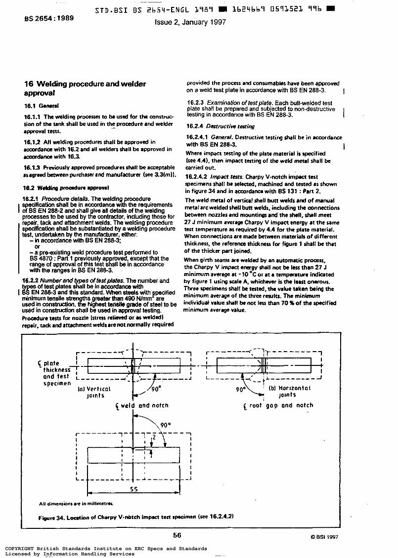
BS 2654 : 1989
16 Welding procedure and welder approval
16.1 &Md
16.1.1 The welding proccrsses to be used for the construc- tion of the tank shall be used in the procedure and welder approval tests.
16.1.2 All welding procedures shall be approved in accordance with 16.2 and all welders h a i l be approved in accordance with 16.3.
16.13 Previously approved prooedwes shall be acceptable asagreed betwcenpurchaserand manufacturer (see 3,3(m)l.
16.2 Welding proœdure rpprovrl
16.2.1 P m d u m details. The welding rocedure specification shall be in accordance W& the requirements
processes to be used by the contractor, including those for repair, tack and attachment welds. The welding procedure specification shall be substantiated by a welding procedure test, undertaken by the manufacturer, either:
- ..-
I of ES EN 288-2 and shall give all details ofthe welding
- in accordance with BS EN 28&3;
- a pre-existing weld procedure test perfonned to ES 4870 : Part 1 previously approved, except that the range of approval of this test shall be in accordance with the ranges in BS EN 288-3.
16.2.2 Number and &Ws oftestplates. The number and
I #&N 288-3 and this standard. When steels with pecified minimum tensile stren S greater than 490 N/mm are used in consbudion, highest tensile grade of steel to be used in construction shall be used in approval testing. f iomure tests for nozzle (stress relieved or as welded) repair, ta& and attachment welds amnot normlly required
or
S of test plates shall be in accordance with
provided the procers and consumabler have been approved on a weld test plate in accordance with BS EN 288-3.
16.2.3 Examinafion offesf plate. Each butt-welded test plate shall be prepared and subjected to nondestructive testing in accordance with BS EN 288-3. I 16.2.4 Oestmctiw testing
16.2.4.1 General. Destructive testing shall be in iccordance with BS EN 2883. Where impact testing of the plate material ir specified (see 4.41, then impact testing of the weld metal shall be carried out. 16.2.4.2 lmpact tesr$- Charpy V-notch impact test specimens shall be sekcted, machined and tested as shown in figure 34 and in accordancc with 6s 131 : Part 2. The weld metal of vertical shell butt welds and of manual metal arc welded shell butt welds, including the c6nmctions between nozzles and mountings and the shell. shall meet 27 J minimum average Charpy V impact energy at the same test temperature as required by 4.4 for the plate material. When connections are made between materials of differm thickness, the reference thickness for figure 1 shall be that of the thicker part joined. When girth seam are welded by an automatic proas, the Charpy V impact energy shall not be lcsr than 27 J minimum average at -IO OC or at a temperature indiated by figure 1 using scale A, whichever is the least onerous. Three w i m e n r shall be tested, the value taken being the minimum average of the three rcrultr. The minimum individual value shall be not less than 70 % of the specified minimum average value.
I
I
1 plate thickness7-
specimen (al Verttcal
Joints 1 weid ond notch
r"""-4 ?r """" "
1
L"""
lb1 Hor!zontal
root g a p and notch
Joints
5 5
56 O BSI 1997
COPYRIGHT British Standards Institute on ERC Specs and StandardsLicensed by Information Handling ServicesCOPYRIGHT British Standards Institute on ERC Specs and StandardsLicensed by Information Handling Services
16.2.4.3 Retem. If one or more Charpy specimen fails to a~mply with 16.24.2. three further specimens shal l be prepared and tested. If any of the retests fail to comply with 16.2.4.2, the pro- adure shall be deemed not to comply with this standard and a new procedure shall be tested. NOTE. Hudnrss I t 'n'rccommendcd that it is desnonstratod in the pmcadurr tests thmt the hardness of the hut-.ffmed zone at the
and pmmt plMe n other loations in the shell. should not exceed Mo HV (utin0 30 kg l0af.I). Where wat H,S conditions are to tm encountered and an piate low h l of h r r d m s canot be obtained. th. mon'ruitable m y to .void stmu corrosion cracking will be to protect the shell to mnulu weld m 8nd iha d u e n t vetticd JHll and annular platt we& using M pproprhte paint.
s ~ M tQ b t tm pbt. a d Of the -Id M l . h8rtJfhCtad 20-
16.25 U)anges rØØering qDpmm1. A welding procedure test shall k required when any of the changas rpecificd
approved welding procedure. I in BS EN 288-3 and/or the following are made to an
(a) A chrnge of brand of hydrogenuxWolled welding electrode or in automatic welding conrumables, except for the wire in r u ~ - a r c welds . (b) Foc a specified wekl prapvrtion in plates 12.5 mm thick and thidter, a dunge of more than f 25 % in the number of runs If the cross-sectional area of the groove ir increased, it io permissible to increase the number of runs in proportion to the increase in area. (c) For automatic girthseam welding, a change from multiple NM per side to single run per side. (dl For automatic girthseam welding, a change from single arc to multiple arc or vice-versa.
16.3 Approval process for welders
lh3.1 Appmva/ of weldem. Each welder shall be approved before welding on the tank. A welder who h a s succcssfull~ welded the proadure test plate shall be considered to have bten .pprovcd.
16.32 ~ m v a l tms. Each welder shall be approved in I accordanœ with BS EN 287-1 and this standard, except for
the following applications.
(a) U n h specifically required by the purchaser (sa 3.2(m)), a welder who io only required to make filkt welds on the tank bottom, roof or shell plates not exceeding 12.5 mm thidtness, except for the shell-to- bottom weld, is not required to pas an approval test, but his standard of workmanship shall be arch that the requirements of this standard are maintained. lb) Ta& welding of shell, roof or bottom, where the tack weld shall be removed by gouging or shall be completely h&, can be carried out by non-appraved optraton who are suitably instructed and supervised to the purchaser's satisfaction when permitted by the
purchaser (see 3.2(n)). Othemise, approved welders shall carry out these optrations.
16.3.3 Examination of welders' fest plates. Each butt-welded test-plate shall be tested in accordance with
16.3.4 E x t m ofappmul. A welder who has success- fully welded the specified tests shall be approved to the extent specified in BS EN 287-i except that:
(a) a welder who has cuaxstfully welded the tests using a basic coated electrode shall be approved to use rutile, cellulosic or iron powder coated electrodes; (bl a welder who has sucoessfully welded the tests wing a rutile coated electrode shall be approved to use allu- losic or iron powder coated electrodes; (c) a change from single arc to multiple arc or vice versa for welders operating automatic or mi-automatic machines requires re-testing.
BS EN 287-1.
1
163.5 Records
16.3.5.1 Copies of the records of each welder's approval shall be available for examination on site by the purchaser (see 3.4(dI).
16.3.5.2 A welder who has been approved shall not be prevented from undenaking production work pending examination of these recordo. or artifad copies of these records, provided 163.5.1 has been complied with.
17.1 Application The proadwe specified in this clause shall apply to the inspection of the joints listed in 17.3. Radiographic examination of fillet welds shall not be required.
17.2 Preparation for rumiruth Surface dressing of buttwelded teems n not normally required except that surface irregularities which may confuse or mask any objectionable defect shill1 be care- fully removed.
17.3 Extent of radiography par tank
17.3.1 The extent of radiography shall be not las than that listed in table 6 for each plate thickness. but shall include one radiugraph taken from the first completed vertical joint for each welding process and thickness, if differing by more than 5 3 mm, welded by each welder. Thereafter, without regard to the number of welders working thereon, the same incidence of radiography shall be maintained. NOTE. The location of the radiographs ir to be d e t e r m i n a d in agreement with the ourchaser.
O BSI 1997
57
COPYRIGHT British Standards Institute on ERC Specs and StandardsLicensed by Information Handling ServicesCOPYRIGHT British Standards Institute on ERC Specs and StandardsLicensed by Information Handling Services
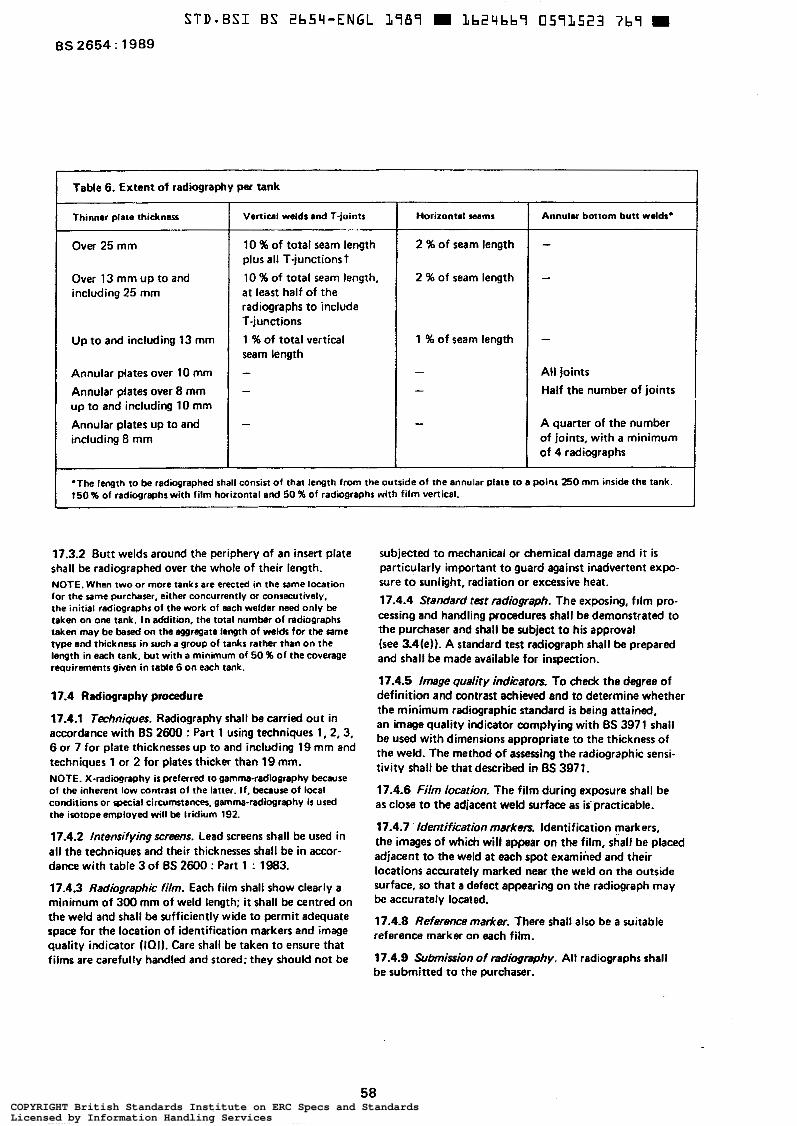
Table 6. Extent of radiography per tank ~~
Thinner plate thickness
Over 25 mm
Over 13 mm up to and including 25 mm
Up to and including 13 mm
Annular plates over 10 mm
Annular plates over 8 mm up to and including 10 mm
Annular plates up to and including 8 mm
Vertical welds and T-joints
10 % of total seam length plus all T-junctions t 10 % of total seam length, at least half of the radiographs to include T-junctions 1 % of total vertical seam length
Horizontal seams Annular bottom butt welds'
2 % of seam length
- 2 96 of seam length
-
1 % of seam length -
All joints Half the number of joints
I A quarter of the number of joints, with a minimum of 4 radiographs
*The length to be radiographed shall consist of that length from the outside of the annular plate to a point B O mm inside the tank. t50 % of radiographs with film horizontal and 50 % of radiographs with film vertical.
17.3.2 Butt welds around the periphery of an insert plate shall be radiographed over the whole of their length. NOTE. When two or more tanks are erected in the rame location for the rame purchaser, either concurrently or consecutively. the initial radiographs of the work of each welder need only be taken on one tank. In addition, the total number of radiographs taken may be based on the eggregate length of welds for the same type and thickness in such a group of tanks rather than on the length in each tank, but with a minimum of 50 % of the coverage requirements given in table 6 on each tank.
17.4 Radiography procedure
17.4.1 Tmhniques. Radiography shall be carried out in accordance with BS 2600 : Part 1 using techniques 1,2,3, 6 or 7 for plate thicknesses up to and including 19 mm and techniques 1 or 2 for plates thicker than 19 mm. NOTE. X-radiography ir preferred to gamma-radwgraphy because of the inherent low contrasí of the latter. If. because of local conditions or special circumstances, gamma-radiography is used the isotope employed will be Iridium 192.
17.4.2 lntensifying screens. Lead Screens shall be used in all the techniques and their thicknesses shall be in accor- dance with table 3 of BS 2600 : Part 1 : 1983.
17.4.3 Radiographic film. Each film shall show clearly a minimum of 300 mm of weld length; it shall be centred on the weld and shall be sufficiently wide to permit adequate space for the location of identification markers and image quality indicator (lar). Care shall be taken to ensure that films are carefully handled and stored: they should not be
subjected to mechanical or chemical damage and it is particularly important to guard against inadvertent expo- sure to sunlight, radiation or excessive heat.
17.4.4 Standard test radiograph. The exposing, film pro- cessing and handling procedures shall be demonstrated to the purchaser and shall be subject to his approval (see 3.4(e)). A standard test radiograph shall be prepared and shall be made available for inspection.
17.4.5 Image quality indicators. To check the degree of definition and contrast achieved and to determine whether the minimum radiographic standard is being attained, an image quality indicator complying with BS 3971 shall be used with dimensions appropriate to the thickness of the weld. The method of assessing the radiographic sensi- tivitv shall be that described in BS 3971.
17.4.6 Film location. The film during exposure shall be as close to the adjacent weld surface as is' practicable.
17.4.7 ' ldentificafion markers. Identification markers, the images of which will appear on the film, shall be placed adjacent to the weld at each spot examined and their locations accurately marked near the weld on the outside surface, u) that a defect appearing on the radiograph may be accurately located.
17.4.8 Reference marker. There shall also be a suitable reference marker on each film.
17.4.9 Submission of radiognphy. All radiographs shall be submitted to the purchaser.
58 COPYRIGHT British Standards Institute on ERC Specs and StandardsLicensed by Information Handling ServicesCOPYRIGHT British Standards Institute on ERC Specs and StandardsLicensed by Information Handling Services
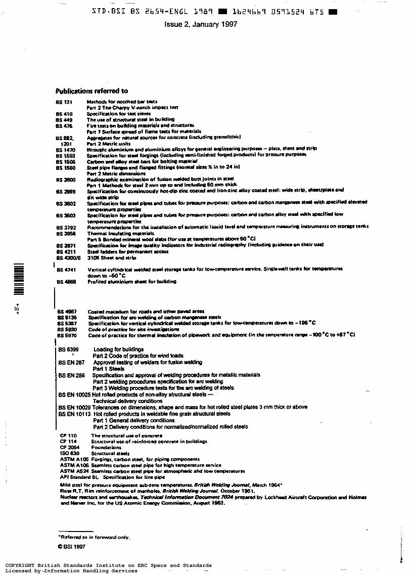
STD-BSI BS 2b5q-ENGL 1989 m Lb24bb7 0571524 bT5 m Issue 2, January 1997
Publications referred to 8s 131
8s 410 8s 449 85 476
8s 882. 1201
BS 1470 BS 1503 BS 1506 BS lb60
BS itwo
SS2989
0s 3602
BS 3603
8s 3792 es 3918
BS 3971 BS 421 1 BSuoo16
0S 4741
BS 4868
I
I SS $987 Bs S135 8s 5387 8s S m
Loading for buildings Part2Cadeofpradicaforwindbads
. ..
'Referred to in formard only.
Q B S I 1997
COPYRIGHT British Standards Institute on ERC Specs and StandardsLicensed by Information Handling ServicesCOPYRIGHT British Standards Institute on ERC Specs and StandardsLicensed by Information Handling Services
Issue 2, January 1997 BS 2654 : 1989 Th& &ithh S-, hdng been pmparud u& thc dmi- of the V.rr(l Smndœda Pole Commime. yv.2 puMished Orders for all BSI, international and foreign standards
Buying standards
unrkr th. a d m d t y of th. LIord of BSI and wmes into effect on publications should be addressed to Customer Services, Sales ZB"1- Department at Chiswick: Tel: 0181 996 7000; e Bridrt, stwdrdr I n n i n n ¡ , 1989 Fax: 0181 996 70131.
In response to orders for international standards, it is BSI policy ta supply the BSI implementation of those that have been published as British Standards, unless othemrise requested.
Fint mridocl.canbind .I BS 2654. February 1973 M dskn owemkr 1984 NW.didocr&pmnbrr1989
I S B N O ~ 1 7 6 6 1 4 Database, the BSI Information Technology Service (BITS) and
ThrfdkrvlngBsl"mthrrwrkon*bmnbrd: DepartmentatChswick:Tel:01819967111; m nf'MnOr PVEIIS Orrft for 87/77053 DC . 0181 996 7048.
Information on standards BSI provides a wide range of information on national, European and intemational standards through its Library, the Standardline
its Technical Help to Exporters Service. Contact the Information
BSI io the independent national body responsible for preparing British Standards. It presents the UK review on standards in Europe and at the intemstional level. It is incorporated by Royal Charter.
-m- A British Standard does not purport to include all the necessary provis+ of a contrsct Users of British Standards are responwble for their correct application.
Revidonr British Standards are updated by amendment or revision. Users of British Standards should make sure that they possess the Mest amendments or editions. it is the constant aim of BSI to improve the qual¡ of our products and services. We would be grateful if anyone finding an inaccuracy or ambiguity while using this British Standard would inform the Secratsrv of the responsible technical committee, the identhy of which can be found on the inside front cover. Tel: 0181 998 9OOO; Fax: 0181 996 7400. BSI offers members an individual updating service called PLUS which ensures that wbscri i automatically receive the latest editions of standards.
Subscribing members of BSI are kept up to date with @andards developments and receive substantial discounts on the purchase price of standards. For details of these and other benefii contact Customer Services, Membership at Chiswick: Tel: 0181 996 7002; Fax: 0181 996 7001.
CoPVriSM Copyright subsists in all BSI publications. BSI also hdds the copyright, in the UK, of the publications of the international standardization bodies. Except as permitted under the Copvright, Designs and Patents Act 1988 no extract may be reproduced, stored in a retrieval system or transmitted in any form or by any means - electronic, photocopying, recording or otherwise - without prior written permission from BSI.
This does not preclude the free use, in the course of implementing the standard, of necessary details such as symbols, and size, type or grade designations. If these details are to be used for any other purpose than implementation then the prior written permission of BSI must be obtained.
If permisu'on is granted, the terms may include royalty payments or a licensing agreement. Details and advice can be obtained from the Copyright Manager, BSI, 389 Chiswick High Road. London W4 4AL
Amendments issued since publication
Amd. No.
Indicated in the margin by a sideline January 1997 9297
Text affected Date of issue
British Standards Institution - 389 Chiswick High Road London W4 4AL - Telephone 0181 996 9O00 * Fax 0181 7400
WEH5 -
COPYRIGHT British Standards Institute on ERC Specs and StandardsLicensed by Information Handling ServicesCOPYRIGHT British Standards Institute on ERC Specs and StandardsLicensed by Information Handling Services