
BRUTUS HDPTO -...
136
Owner's Manual for Maintenance and Safety BRUTUS™ BRUTUS™ HD BRUTUS™ HDPTO
Transcript of BRUTUS HDPTO -...

Owner's Manualfor Maintenance and Safety
BRUTUS™BRUTUS™ HD
BRUTUS™ HDPTO

WARNINGRead, understand, and follow all of the instructions and safety precautions in this manual and on all product labels.Failure to follow the safety precautions could result in serious injury or death.
WARNINGThe engine exhaust from this product contains chemicals known to the State
of California to cause cancer, birth defects or other reproductive harm.
1
WELCOMEThank you for purchasing a POLARIS vehicle, and welcome to our world-wide family of POLARIS enthusiasts. Be sure to visit us online at www.polaris.com for the latest news, new product introductions, upcoming events, career opportunities and more.Here at POLARIS we proudly produce an exciting line of utility and recreational products.• Snowmobiles• All-terrain vehicles (ATVs)• Low emission vehicles (LEVs)• BRUTUS™ utility vehicles• RANGER® utility vehicles• RZR® sport vehicles• VICTORY® motorcycles• GEM® electric vehiclesWe believe POLARIS sets a standard of excellence for all utility and recreational vehicles manufactured in the world today. Many years of experience have gone into the engineering, design, and development of your POLARIS vehicle, making it the finest machine we’ve ever produced.For safe and enjoyable operation of your vehicle, be sure to follow the instructions and recommendations in this owner’s manual. Your manual contains instructions for minor maintenance, but information about major repairs is outlined in the POLARIS Service Manual and should be performed only by a Factory Certified Master Service Dealer® (MSD) Technician.Your POLARIS dealer knows your vehicle best and is interested in your total satisfaction. Be sure to return to your dealership for all of your service needs during, and after, the warranty period.

2
POLARIS® and BRUTUS™ are trademarks of POLARIS Industries Inc.Copyright 2014 Polaris Industries Inc. All information contained within this publication is based on the latest product information at the time of publication. Due to constant improvements in the design and quality of production components, some minor discrepancies may result between the actual vehicle and the information presented in this publication. Depictions and/or procedures in this publication are intended for reference use only. No liability can be accepted for omissions or inaccuracies. Any reprinting or reuse of the depictions and/or procedures contained within, whether whole or in part, is expressly prohibited.The original instructions for this vehicle are in English. Other languages are provided as translations of the original instructions.Printed in U.S.A.2014 BRUTUS Diesel Owner’s ManualP/N 9925212

3
TABLE OF CONTENTSIntroduction . . . . . . . . . . . . . . . . . . . . . . . . . . . . . . . . . . . . . . . . 4Safety . . . . . . . . . . . . . . . . . . . . . . . . . . . . . . . . . . . . . . . . . . . . . 7Features And Controls . . . . . . . . . . . . . . . . . . . . . . . . . . . . . . 19Operation . . . . . . . . . . . . . . . . . . . . . . . . . . . . . . . . . . . . . . . . . 32Attachment Arm . . . . . . . . . . . . . . . . . . . . . . . . . . . . . . . . . . . 65PTO System . . . . . . . . . . . . . . . . . . . . . . . . . . . . . . . . . . . . . . . 69Emission Control Systems . . . . . . . . . . . . . . . . . . . . . . . . . . . 72POLARIS Products . . . . . . . . . . . . . . . . . . . . . . . . . . . . . . . . 119Specifications . . . . . . . . . . . . . . . . . . . . . . . . . . . . . . . . . . . . 120Troubleshooting . . . . . . . . . . . . . . . . . . . . . . . . . . . . . . . . . . 122Warranty . . . . . . . . . . . . . . . . . . . . . . . . . . . . . . . . . . . . . . . . . 123Maintenance Log . . . . . . . . . . . . . . . . . . . . . . . . . . . . . . . . . . 128Index . . . . . . . . . . . . . . . . . . . . . . . . . . . . . . . . . . . . . . . . . . . . 130
4
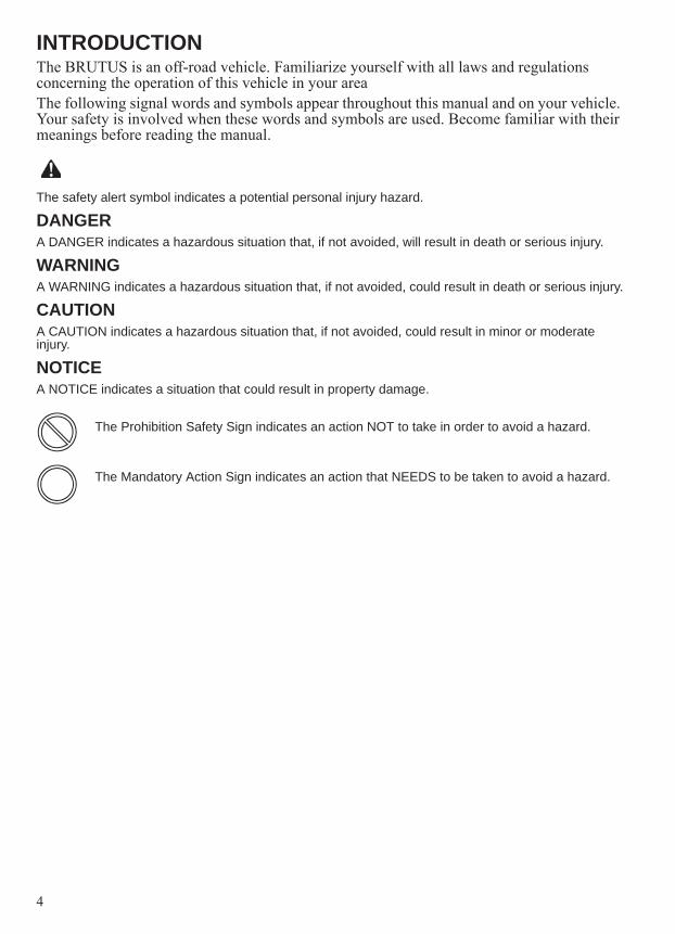
INTRODUCTIONThe BRUTUS is an off-road vehicle. Familiarize yourself with all laws and regulations concerning the operation of this vehicle in your areaThe following signal words and symbols appear throughout this manual and on your vehicle. Your safety is involved when these words and symbols are used. Become familiar with their meanings before reading the manual.
The safety alert symbol indicates a potential personal injury hazard.
DANGERA DANGER indicates a hazardous situation that, if not avoided, will result in death or serious injury.
WARNINGA WARNING indicates a hazardous situation that, if not avoided, could result in death or serious injury.
CAUTIONA CAUTION indicates a hazardous situation that, if not avoided, could result in minor or moderate injury.
NOTICEA NOTICE indicates a situation that could result in property damage.
The Prohibition Safety Sign indicates an action NOT to take in order to avoid a hazard.
The Mandatory Action Sign indicates an action that NEEDS to be taken to avoid a hazard.

5
INTRODUCTION
Failure to follow the warnings contained in this manual can result in severe injury or death.Your POLARIS BRUTUS is not a toy and can be hazardous to operate. This vehicle handles differently than other vehicles, such as cars, trucks or other off-road vehicles. A collision or rollover can occur quickly, even during routine maneuvers like turning, or driving on hills or over obstacles, if you fail to take proper precautions.• Read this owner’s manual. Understand all safety warnings, precautions and operating procedures
before operating the vehicle. Keep this manual with the vehicle.• This vehicle is an ADULT VEHICLE ONLY. You MUST be at least age 16 and have a valid driver’s
license to operate this vehicle.• All operators should take a training course.• No person under the age of 12 may ride as a passenger in this vehicle. All riders must be able to sit
with backs against the seat, both feet flat on the floor and both hands on the steering wheel (if driving) or on a passenger hand hold.
• Never permit a guest to operate this vehicle unless the guest has read this manual and all product labels.
• Always keep hands, feet and all other body parts inside the vehicle at all times.• Always wear a helmet, eye protection, gloves, long-sleeve shirt, long pants and over-the-ankle
boots.• Never use this vehicle with drugs or alcohol, as these conditions impair judgment and reduce
operator reaction time.
WARNING

6
INTRODUCTIONVehicle Identification NumbersRecord your vehicle's identification numbers and key number in the spaces provided. Remove the spare key and store it in a safe place. An ignition key can be duplicated only by ordering a POLARIS key blank (using your key number) and mating it with one of your existing keys. The ignition switch must be replaced if all keys are lost.
Vehicle Model Number: ________________________________________________________________________
Frame VIN: _________________________________________________________________________________
Engine Serial Number: ________________________________________________________________________
Key Number: ________________________________________________________________________________
European Vibration and NoiseThe driver-perceived noise and hand/arm and whole body vibration levels of this machinery is measured per prEN 15997.The operating conditions of the machinery during testing:The vehicles were in like-new condition. The environment was controlled as indicated by the test procedure(s).The uncertainty of vibration exposure measurement is dependent on many factors, including:• Instrument and calibration uncertainty• Variations in the machine such as wear of components• Variation of machine operators such as experience or physique• Ability of the worker to reproduce typical work during measurements• Environmental factors such as ambient noise or temperature
Engine Serial Number
Key Number
####
VIN

7
SAFETYSafe Riding GearAlways wear the proper clothing when operating or riding in this vehicle. All riders should wear substantial footwear, long pants and a close-fitting shirt. A hard hat or helmet and approved eye protection are recommended when appropriate for working or riding conditions. POLARIS recommends wearing approved eye protection bearing markings such as VESC 8, V-8, Z87.1 or CE. Never operate or ride in this vehicle while barefoot or while wearing sandals or tennis shoes.Workplace safety regulations may require the use of safety glasses, safety shoes and a hard hat or helmet. Familiarize yourself with local requirements, be prepared for operating conditions and wear the appropriate safety gear.Rider ComfortUnder certain operating conditions, heat generated by the engine and exhaust system can elevate temperatures in the driver and passenger cab area. The condition occurs most frequently when a vehicle is being operated in high ambient temperatures at low speeds and/or high load conditions for an extended period of time. The use of certain windshield, roof and/or cab systems may contribute to this condition by restricting airflow. Any discomfort due to heat buildup in this area can be minimized by wearing proper riding apparel and by varying speeds to increase airflow.

8
SAFETYSafety and Information LabelsWarning labels have been placed on the vehicle for your protection. Read and follow the instructions of the labels on the vehicle carefully. If any of the labels depicted in this manual differ from the labels on your vehicle, always read and follow the instructions of the labels on the vehicle. If any label becomes illegible or comes off, contact your POLARIS dealer to purchase a replacement. Replacement safety labels are provided by POLARIS at no charge. The part number is printed on the label..
Rotating Parts/PTO Warning(If Equipped)
Discretionary Warning
Age 16 Warning
Shift Caution
To Start Engine / To Leave vehicle
Attachment Arm Warning
(If Equipped)
Seat Switch Warning(If Equipped With PTO)
Towing Warning
Discretionary Warning
Rotating Fan Warning

9
SAFETYSafety Labels and LocationsAge 16 WarningWARNINGNo Operator Under 16Operating this vehicle if you are under the age of 16 increases your chance of severe injury or death.NEVER operate this vehicle if you are under age 16 and NEVER operate this vehicle without a valid driver’s license.
7175566
To Start Engine / To Leave VehicleWARNINGTo Start Engine• Gear Selector must be in PARK, NEUTRAL, or treadle pedal must be in NEUTRAL.• PTO must be OFF (If Equipped).To Leave Vehicle• Put gear selector in PARK.• STOP engine.
7179357
Shift CautionCAUTIONTo avoid transmission damage, shift only when vehicle is stationary and at idle.
7172674
Discretionary WarningWARNINGImproper vehicle use can result in Serious Injury or Death.NEVER Operate:• At speeds too fast for your skills or the conditions.• After or while using Alcohol or Drugs.• Across slopes (Avoid side hilling).• On public roads. This vehicle is for off-highway use only. Driving on public roads could be a violation
of law.• With more passengers than described in the Owner’s Manual, with children under the age of 12, and
passengers who cannot comfortably reach the floor and hand holds with back against the seat.• On paved surfaces – pavement may seriously affect handling and control.• With non-POLARIS approved accessories – they may seriously affect stability.ALWAYS:• Wear your seat belt. Vehicle rollover could cause serious injury or death.• Keep hands and feet in vehicle at all times.• Wear a helmet and eye protection.• Reduce speed and use extra caution when carrying passengers.• Avoid sharp turns or turns while applying heavy throttle.• Operate slowly in reverse - avoid sharp turns or sudden braking.• Make sure passengers read and understand all safety labels.Locate And Read Owner’s Manual. Follow All Instructions And Warnings.
7180852

10
SAFETYSafety Labels and LocationsSeat Switch WarningWARNINGAvoid Injury Or Death• Check that seat switch is properly installed and functions correctly.• Replace switch and components if damaged or missing.
7179343
Attachment Arm WarningWARNINGAvoid Serious Injury Or Death.• Do not exceed attachment arm rated capacity.• Keep bystanders away. No riders on attachment.• Keep hands and body from under attachment.• Do not modify the attachment arm or use unapproved attachments.
7179168
Rotating Parts/PTO WarningWARNINGRotating Parts Can Cause serious Injury Or Death• Keep PTO shield and all guards in place.• Keep away from moving parts.• Keep bystanders away.• Do not exceed the PTO speed of 2000 RPM.See Operation & Maintenance Manual For More Instructions.
7179165
Rotating Fan WarningWARNINGAvoid Serious Injury.Do not operate with shields removed.Do not modify.
7179166
Maximum Trailer Weight WarningWARNINGTowing An Improperly Loaded Trailer Can Cause Loss Of Control Resulting In Serious Injury Or Death.Maximum Tongue Weight: 150 lbs. (68 kg)Maximum Tow Weight: 2000 lbs. (907 kg)See Operation & Maintenance Manual For More Instructions.
7179167

11
SAFETYSafety Labels and LocationsPassenger/Tire Pressure WarningWARNINGFalling Off Cargo Box Can Cause Serious Injury Or Death• Never carry riders in cargo box.WARNINGOverloading Or Improper Tire Pressure Can Cause Tipping Or Loss Of Control Resulting In Serious Injury Or Death.• Never exceed load capacities.• Reduce speed and allow greater distance for braking when carrying cargo.• Carrying tall, off-center, or unsecured loads will increase your risk of losing control. Center and
secure loads as low as possible in box.• Reduce speed and cargo on rough or hilly terrain.• Check for proper tire pressures.
7179171
Model Number BRUTUS BRUTUS HDMAXIMUM CARGO BOX LOAD 1250 lbs. (567 kg) 1250 lbs. (567 kg)ATTACHMENT ARM RATED CAPACITY
500 lbs. (225 kg)
TIRE PRESSURE IN PSI (KPa) FRONT 10 (69)REAR 20 (138)
FRONT 20 (138)REAR 20 (138)
VEHICLE RATED CAPACITYIncludes weight of operator, passenger, cargo, attachment arm rated capacity (BRUTUS HD only), and accessories.
No Cab: 1750 lbs. (794 kg) Cab: 1750 lbs. (794 kg)
No Cab: 2000 lbs. (907 kg) Cab: 1750 lbs. (794 kg)
Read Operation & Maintenance Manual for detailed loading information.
X
12
SAFETYOperator Safety
Serious injury or death can result if you do not follow these instructions and procedures, which are outlined in further detail within your owner's manual.• Read this manual and all labels carefully. Follow the operating procedures described.• Never allow anyone under age 16 to operate this vehicle and never allow anyone without a
valid driver's license to operate this vehicle.• Do not carry passenger until you have at least two hours of driving experience with this
vehicle.• No person under the age of 12 may ride as a passenger in this vehicle. All riders must be
able to sit with backs against the seat, both feet flat on the floor and both hands on the steering wheel (if driving) or on a passenger hand hold.
• The driver and all passengers must wear helmet, eye protection, gloves, long-sleeve shirt, long pants, over-the-ankle boots and seat belt at all times.
• Always keep hands and feet inside the vehicle at all times.• Always keep both hands on the steering wheel and both feet on the floorboards of the
vehicle during operation.• Never permit a guest to operate this vehicle unless the guest has read this manual and all
product labels.• To reduce rollover risk, be especially careful when encountering obstacles and slopes and
when braking on hills or during turns.• This vehicle is for off-road use only. Never operate on public roads (unless marked for off-
road use). Always avoid paved surfaces.• Never consume alcohol or drugs before or while operating this vehicle.• Never operate at excessive speeds. Always travel at a speed proper for the terrain,
visibility and operating conditions, and your experience.• Never attempt jumps or other stunts.• Always inspect the vehicle before each use to make sure it's in safe operating condition.
Always follow the inspection procedures described in this manual.• Always travel slowly and use extra caution when operating on unfamiliar terrain. Be alert
to changing terrain.• Never operate on excessively rough, slippery or loose terrain.• Always follow proper procedures for turning. Practice turning at slow speeds before
attempting to turn at faster speeds. Never turn at excessive speeds.• Always have this vehicle checked by an authorized POLARIS dealer if it has been
involved in an accident.• Never operate this vehicle on hills too steep for the vehicle or for your abilities. Practice
on smaller hills before attempting larger hills.• Always follow proper procedures for climbing hills as described in this manual. See page
51. Check the terrain carefully before attempting to climb a hill. Never climb hills with excessively slippery or loose surfaces. Never apply throttle suddenly. Never make sudden gear changes. Never go over the top of a hill at high speed.
WARNING

13
SAFETYOperator Safety• Always follow the proper procedures outlined in this manual for traveling downhill and
for braking on hills. See page 52. Check the terrain carefully before descending a hill. Never travel downhill at high speed. Avoid going downhill at an angle, which would cause the vehicle to lean sharply to one side. Travel straight down the hill where possible.
• Always check for obstacles before operating in a new area. Never attempt to operate over large obstacles such as large rocks or fallen trees. Always follow the proper procedures outlined in this manual when operating over obstacles. See page 53.
• Always be careful of skidding or sliding. On slippery surfaces such as ice, travel slowly and exercise caution to reduce the chance of skidding or sliding out of control.
• Never operate your vehicle in fast-flowing water or in water deeper than that specified in this manual. See page 54. Wet brakes may have reduced stopping ability. Test your brakes after leaving water. If necessary, apply them lightly several times to let friction dry out the pads.
• Always be sure there are no obstacles or people behind your vehicle when operating in reverse. When it's safe to proceed in reverse, move slowly. Avoid turning at sharp angles in reverse.
• Always use the proper size and type of tires specified in this manual. Always maintain proper tire pressure as specified on safety labels.
• Never modify this vehicle through improper installation or use of non-POLARIS-approved accessories.
• Never exceed the stated load capacity for this vehicle. Cargo should be properly distributed and securely attached. Reduce speed and follow the instructions in this manual for hauling cargo, with attachments installed or pulling a trailer. Allow a greater distance for braking. Keep the attachment arm low (if equipped) and slow down when turning.
• Always place the transmission in PARK before getting out of the vehicle.• Disengage PTO (if equipped), put the gear selector in PARK, stop the engine and make
sure all rotating components are stopped before exiting utility vehicle.• Always stop the engine before refueling. Remove flammable material containers from the
box before filling them with fuel. Make sure the refueling area is well ventilated and free of any source of flame or sparks. Fuel is extremely flammable. See page 36 for fuel safety warnings.
• Always remove the ignition key when the vehicle is not in use to prevent unauthorized use by someone under the age of 16 or without a driver’s license and proper training, or accidental starting.

14
SAFETYOperator Safety
Failure to operate the BRUTUS properly can result in a collision, loss of control, accident or rollover, which may result in serious injury or death. Heed all safety warnings outlined in this section of the owner’s manual. See the OPERATION section of the owner’s manual for proper operating procedures.
Age RestrictionsThis vehicle is an ADULT VEHICLE ONLY. NEVER operate this vehicle if you are under age 16 and NEVER operate without a valid driver’s license.Never operate with a passenger under the age of 12. All riders must be able to sit with backs against the seat, both feet flat on the floor and both hands on the steering wheel (if driving) or on a passenger hand hold.
Operating Without InstructionOperating this vehicle without proper instruction increases the risk of an accident. The operator must understand how to operate the vehicle properly in different situations and on different types of terrain. All operators must read and understand the Owner's Manual and all warning and instruction labels before operating the vehicle.
Using Alcohol or DrugsOperating the vehicle after consuming alcohol or drugs could adversely affect operator judgment, reaction time, balance and perception.Never drink alcohol or use drugs or medications before or while operating this vehicle.
Seat BeltsRiding in this vehicle without wearing the seat belt increases the risk of serious injury in the event of rollover, loss of control, other accident or sudden stop. Seat belts may reduce the severity of injury in these circumstances. All riders must wear seat belts at all times.
WARNING

15
SAFETYOperator SafetyFailure to Inspect Before OperatingFailure to inspect and verify that the vehicle is in safe operating condition before operating increases the risk of an accident. Always perform the pre-ride inspection before each use of your vehicle to make sure it's in safe operating condition. See page 33. Always follow all inspection and maintenance procedures and schedules described in this owner's manual. See page 73.
Operating With a Load on the VehicleThe weight of both cargo and passengers impacts vehicle operation. For your safety and the safety of others, carefully consider how your vehicle is loaded and how to safely operate the vehicle. Follow the instructions in this manual for loading, tire pressure, gear selection and speed.• Do not exceed vehicle weight capacities. The vehicle’s maximum weight capacity is listed in the
specifications section of this manual and on a label on the vehicle. When more passenger weight is added, cargo weight may need to be reduced accordingly.
• The recommended tire pressures are listed in the specifications section of this manual and on a label on the vehicle.
Always follow these guidelines:
Under ANY of these conditions: Do ALL of these steps:Passenger and/or cargo exceeds half the maximum weight capacity
1. Slow down.2. Verify tire pressure.3. Use extra caution when operating.Operating in rough terrain
Operating over obstaclesClimbing an inclineTowingOperating with attachments installed

16
SAFETYOperator SafetyExposure to ExhaustEngine exhaust fumes are poisonous and can cause loss of consciousness or death in a short time. Never start the engine or let it run in an enclosed area.The engine exhaust from this product contains chemicals known to cause cancer, birth defects or other reproductive harm. Operate this vehicle only outdoors or in well-ventilated areas.
Operating a Damaged VehicleOperating a damaged vehicle can result in an accident. After any rollover or other accident, have a qualified service dealer inspect the entire machine for possible damage, including (but not limited to) seat belts, rollover protection devices, brakes, throttle and steering systems.
Operating at Excessive SpeedsOperating this vehicle at excessive speeds increases the operator's risk of losing control. Always operate at a speed that's appropriate for the terrain, the visibility and operating conditions, your skills and your passengers’ skills and experience.
Turning ImproperlyTurning improperly could cause loss of traction, loss of control, accident or rollover. Always follow proper procedures for turning as described in this owner’s manual. Never turn abruptly or at sharp angles. Never turn at high speeds. Practice turning at slow speeds before attempting to turn at faster speeds.
Operating on PavementThis vehicle's tires are designed for off-road use only, not for use on pavement. Operating this vehicle on paved surfaces (including sidewalks, paths, parking lots and driveways) may adversely affect the handling of the vehicle and could result in loss of control and accident or rollover.Avoid operating the vehicle on pavement. If it's unavoidable, travel slowly and avoid sudden turns or stops.
Operating on Public RoadsOperating this vehicle on public streets, roads or highways could result in a collision with another vehicle.Never operate this vehicle on any public street, road or highway, including dirt and gravel roads (unless designated for off-highway use). In some areas it's unlawful to operate this vehicle on public streets, roads and highways.
Jumps and StuntsAttempting wheelies, jumps and other stunts increases the risk of an accident or rollover. Never attempt wheelies, jumps, or other stunts. Avoid exhibition driving.
Operating in Unfamiliar TerrainFailure to use extra caution when operating on unfamiliar terrain could result in an accident or rollover. Unfamiliar terrain may contain hidden rocks, bumps, or holes that could cause loss of control or rollover.Travel slowly and use extra caution when operating on unfamiliar terrain. Always be alert to changing terrain conditions.

17
SAFETYOperator SafetyOperating on Slippery TerrainFailure to use extra caution when operating on excessively rough, slippery or loose terrain could cause loss of traction, loss of control, accident or rollover. Do not operate on excessively slippery surfaces. Always slow down and use additional caution when operating on slippery surfaces.Skidding or sliding due to loss of traction can cause loss of control or rollover (if tires regain traction unexpectedly). Always follow proper procedures for operating on slippery surfaces as described in this owner's manual. See page 52.
Improper Hill ClimbingClimbing hills improperly can cause loss of control or vehicle rollover. Always follow proper procedures for climbing hills as described in this owner's manual. See page 51.
Descending Hills ImproperlyImproperly descending a hill could cause loss of control or rollover. Always follow proper procedures for traveling down hills as described in this owner’s manual. See page 52.
Stalling While Climbing a HillStalling or rolling backwards while climbing a hill could cause an rollover. Always maintain a steady speed when climbing a hill..If all forward speed is lost (engine running):• Use the treadle pedal to slowly back the vehicle straight downhill.• If necessary, apply brake pressure to control speed.If all forward speed is lost (engine not running):• Apply the brakes and attempt to restart the engine.• If engine will not restart, place transmission in neutral and slowly allow the vehicle to roll straight
downhill while applying brake pressure to control speed.
Improper Tire MaintenanceOperating this vehicle with improper tires or with improper or uneven tire pressure could cause loss of control or accident.Always use the size and type of tires specified for your vehicle.Always maintain proper tire pressure as described in the owner's manual and on safety labels.
Operating on Frozen Bodies of WaterSevere injury or death can result if the vehicle and/or the operator fall through the ice. Never operate the vehicle on a frozen body of water unless you have first verified that the ice is sufficiently thick to support the weight and moving force of the vehicle, you and your passengers, and your cargo, together with any other vehicles in your party. Always check with local authorities and residents to confirm ice conditions and thickness over your entire route. Vehicle operators assume all risk associated with ice conditions on frozen bodies of water.
18
SAFETYOperator SafetyUnauthorized Use of the VehicleLeaving the keys in the ignition can lead to unauthorized use of the vehicle by someone under the age of 16, without a drivers license, or without proper training. This could result in an accident or rollover. Always remove the ignition key when the vehicle is not in use.
Hot Exhaust SystemsExhaust system components are very hot during and after use of the vehicle. Hot components can cause burns and fire. Do not touch hot exhaust system components. Always keep combustible materials away from the exhaust system. Use caution when traveling through tall grass, especially dry grass, to avoid debris build-up around the exhaust system.
Attachment Arm System (If Equipped)The dealer explains the capabilities and restrictions of the BRUTUS utility vehicle, attachment and accessories for each application. The dealer demonstrates the safe operation according to POLARIS instructional materials, which are also available to operators. The dealer can also identify unsafe modifications or use of unapproved attachments and accessories. The attachments and buckets are designed for an attachment arm Rated Capacity. They are designed for secure fastening to the BRUTUS utility vehicle. The user must check with the dealer, or POLARIS literature, to determine safe loads of materials of specified densities for the vehicle - attachment combination.
Safety Rules For Power Take-Off (PTO) Driven Attachments (If Equipped)• Keep PTO shields and all guards in place. Replace damaged or missing shields and guards before
operating.• Follow warnings and instructions on machine signs (decals). Replace damaged or missing decals.• Do not wear loose or bulky clothing around the PTO or other moving parts.• Keep bystanders away from PTO driven equipment, and never allow children near machines.• Read and understand the manuals for the PTO driven equipment and be aware of safe operating
procedures and hazards that may not be readily apparent.• Always walk around equipment to avoid coming near a turning PTO driveline. Stepping over, leaning
across or crawling under a turning PTO driveline can cause entanglement.• Position the machine and attachment correctly to prevent driveline stress.• Use caution when raising PTO driven attachment. Excessive driveline angle can reduce driveline
service life.
Equipment ModificationsDo not install any non-POLARIS-approved accessory or modify the vehicle for the purpose of increasing speed or power. Any modifications or installation of non-POLARIS-approved accessories could create a substantial safety hazard and increase the risk of bodily injury.The warranty on your POLARIS vehicle will be terminated if any non-POLARIS-approved equipment and/or modifications have been added to the vehicle that increase speed or power.The addition of certain accessories, including (but not limited to) mowers, blades, tires, sprayers, or large racks, may change the handling characteristics of the vehicle. Use only POLARIS-approved accessories and attachments, and familiarize yourself with their function and effect on the vehicle.For More Information About Safety, call POLARIS at 1-800-342-3764.
19
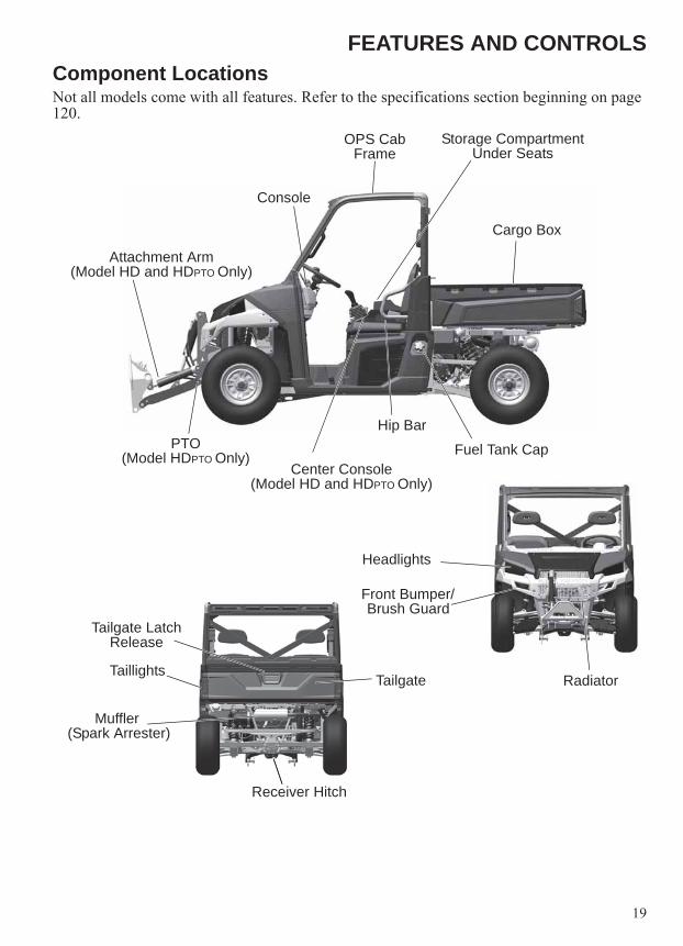
FEATURES AND CONTROLSComponent Locations Not all models come with all features. Refer to the specifications section beginning on page 120.
Front Bumper/Brush Guard
OPS Cab Frame
Console
Hip Bar
Cargo Box
Fuel Tank Cap
Tailgate Latch Release
Receiver Hitch
Muffler (Spark Arrester)
Tailgate
Storage CompartmentUnder Seats
Headlights
Center Console(Model HD and HDPTO Only)
Attachment Arm(Model HD and HDPTO Only)
PTO(Model HDPTO Only)
TaillightsRadiator

20
FEATURES AND CONTROLSSwitches and Indicator Lights
Ignition SwitchThe ignition switch is a three-position, key-operated switch. The key can be removed from the switch in the OFF position.
Mode ButtonThe button located on the instrument cluster is used to toggle through mode options. See pages 26-31.Power Lift Assist Switch (Box Dump Switch)Use this switch to dump the cargo. See page 57.
OFF The engine is off. Electrical circuits are off, except Acc, 12V.
ON Electrical circuits are on. Electrical equipment can be used.
START After the wait-to-start indicator turns off, turn the key to the START position to engage the electric starter. The key returns to the ON position when released.
Ignition Switch
Light Switch
AWD/Differential SwitchPower Lift Assist Switch
(If Equipped)
Blank Switch Openings (Available For Accessories)
HVAC Switches (If Equipped)
Mode Button
Ignition Switch
Light Switch
AWD/Differential SwitchPower Lift Assist Switch
(If Equipped)
Blank Switch Openings (Available For Accessories)
HVAC Switches (If Equipped)
Mode Button
STARTOFFON

21
FEATURES AND CONTROLSSwitches and Indicator LightsLight SwitchThe ignition switch must be in the ON position to operate the headlights.Press the top of the rocker switch toward the dash to place the headlights on high beam.Move the rocker switch to the center position to place the headlights on low beam.Press the bottom of the rocker switch to turn off the headlights.AWD/Differential Lock SwitchThe AWD/Differential Switch has three positions:• All Wheel Drive (AWD)• Differential Lock (2WD)• Differential UnlockPress the top of the rocker switch to engage All Wheel Drive (AWD). See page 61 for operating instructions.Move the rocker switch to the center position to lock the differential and operate in rear wheel drive. Press the bottom of the switch to unlock the differential and allow the two rear drive wheels to operate independently. See page 61 for differential lock operating instructions.HVAC Switches (If Equipped)If equipped with a Cab with HVAC (Heat and Air Conditioning):• Fan Switch (OFF-Low-Med-High)• Air Conditioning (Press top of switch to turn Air
Conditioning ON, bottom for OFF)• Temperature Control Switch (Rotate clockwise to
increase temperature, counter-clockwise to decrease)Wiper Switch (If Equipped)If equipped with a cab with a wiper, the front wiper switch is located on the wiper motor cover at the top of the front window:• Wiper Switch (OFF-Low-High)• Washer Switch (Press and hold top of switch to activate
window washer)
HIGH
OFF
LOW
AWD
Differential Lock
Differential Unlock
Fan A/COn-Off
Temp Control
WiperSwitch
WasherSwitch

22
FEATURES AND CONTROLSConsole
Auxiliary OutletsThe 12-volt receptacles have spade connections on the back that may be used to power an auxiliary light or other optional accessories or lights. The connections are behind the console, under the dash.Gear SelectorUse the gear selector to shift gears. Low gear is the primary driving range for the BRUTUS. High gear is intended for use on hard-packed surfaces with light loads. To shift gears, brake to a complete stop. When the engine is idling, move the lever to the desired gear.NOTICE: Shifting gears with the engine speed above idle or while the vehicle is moving could cause
transmission damage. Always shift when the vehicle is stationary and the engine is at idle.Tip: Maintaining shift linkage adjustment is important to assure proper transmission function. See your
dealer if you experience any shifting problems.
Adjustable Steering WheelThe steering wheel can be tilted upward or downward for rider preference.Lift and hold the adjustment lever toward you while moving the steering wheel upward or downward. Release the lever when the steering wheel is at the desired position.
Cup Holder
12V AuxiliaryOutlets
StorageTray
Instrument Cluster
Gear Selector (Shifter)
Steering Wheel Storage
Compartment
Cup Holder
Lever

23
FEATURES AND CONTROLSCenter Console (For Models HD and HDPTO Only)Joystick - Attachment ArmMovement of the joystick controls the lift and tilt functions of the attachment arm and the PRO-TACH attachment system. See page 42.Engine Speed (RPM) Control LeverThe engine speed (RPM) control lever controls engine RPM. This is used to set engine RPM separately from the travel speed when using attachments. See page 45.Power Take-Off (PTO)The front PTO is available on model HDPTO only. The PTO has a rated speed of 2000 RPM. The PTO is used to power some attachments. See page 63.WARNING! Do NOT exceed the rated attachment PTO speed. Stay clear of rotating driveline. Keep bystanders away. Keep PTO shields and all guards in place. Disengage PTO, put the gear selector in PARK, stop the engine and make sure all rotating components are stopped before exiting utility vehicle. Do NOT service the utility vehicle or attachment with the PTO engaged. Do NOT service the attachment in a raised position unless properly blocked and with all rotating components stopped. Disengage PTO for road travel.
Joystick Lockout SwitchThe joystick lockout switch is used to activate or lock out the joystick functions. The joystick should be locked when no attachments are installed. This will keep the joystick from accidentally being activated. See page 42.Tilt Lockout SwitchThe tilt lockout switch locks out the tilt function. See page 42.Tip: When operating PTO driven attachments, the tilt lockout switch will automatically activate. Using
the attachment with the tilt locked out will limit the possibility of tilting the attachment while the PTO shaft is turning and putting stress on the PTO driveline u-joints. Before engaging the PTO system, tilt the attachment to the desired operating position. See your attachment owner’s manual for detailed information.
Front Auxiliary Hydraulic SwitchThe front auxiliary hydraulic switch controls hydraulic flow to the front male and female coupler for attachment operation. See page 43.
JoystickRPM
Control LeverPTO
Front AuxiliaryHydraulic Switch
Tilt Lockout Switch
Joystick Lockout Switch

24
FEATURES AND CONTROLSOccupant Protective Structure (OPS)The Occupant Protective Structure (OPS) on this vehicle meets ANSI/OPEI B71.9-2012 occupant requirements. Always have your authorized POLARIS dealer thoroughly inspect the OPS if it ever becomes damaged in any way.No device can assure occupant protection in the event of a rollover. Always follow all safe operating practices outlined in this manual to avoid vehicle rollover. WARNING! Vehicle rollover could cause severe injury or death. Always avoid operating in a manner that could result in vehicle rollover.
Storage CompartmentsA storage compartment is located under both the driver’s and passenger seat.
Trailer Hitch BracketThis vehicle is equipped with a receiver hitch bracket for a trailer hitch. To avoid injury and property damage, always heed the warnings and towing capacities outlined on pages 55-57.
Brake PedalDepress the brake pedal to slow or stop the vehicle. Apply the brakes while starting the engine.
Treadle PedalThe treadle pedal is used to control the forward and backward movement of the utility vehicle. The farther the pedal is pressed, the faster the travel speed.Press the toe of the pedal for forward travel, press the heel of the pedal for rearward travel.
OPS
Treadle Pedal
Brake Pedal

25
FEATURES AND CONTROLSSeat RemovalPull up on the rear of the seat and tilt it toward the front of the vehicle. Install the seat by sliding the tabs into the front of the seat base. Push down firmly on the rear of the seat until the pins are fully seated into the grommets.Tip: For Model HDPTO; a seat switch is located under the
operator’s seat. Set the seat aside if possible to avoid disconnecting the seat switch. If the seat switch is disconnected, the harness must be secured in it’s original position to avoid harness damage.
Seat BeltsThis POLARIS vehicle is equipped with three-point lap and diagonal seat belts on all seats. Always make sure the seat belts are secured for all riders before operating.WARNING! Falling from a moving vehicle could result in serious injury or death. Always fasten your seat belt securely before operating or riding in the BRUTUS.To wear the seat belt properly, follow this procedure:1. For 3-point belts, pull the seat belt latch downward
and across your chest toward the buckle at the inner edge of the seat. The belt should fit snugly across your hips and diagonally across your chest. Make sure the belt is not twisted.
2. Push the latch plate into the buckle until it clicks.3. Release the strap, it will self-tighten.4. To release the seat belt, press the square red button in the buckle's center.Seat Belt InspectionInspect all seat belts for proper operation before each use of the vehicle.1. Push the latch plate into the buckle until it clicks. The latch plate must slide smoothly
into the buckle. A click indicates that it's securely latched.2. Push the red release latch in the middle of the buckle to make sure it releases freely. 3. Pull each seat belt completely out and inspect the full length for any damage, including
cuts, wear, fraying or stiffness. If any damage is found, or if the seat belt does not operate properly, have the seat belt system checked and/or replaced by an authorized POLARIS dealer.
4. To clean dirt or debris from the seat belts, sponge the straps with mild soap and water. Do not use bleach, dye or household detergents.
Seat Switch Harness
Model HDPTO Only
Buckle
Latch Plate

26
FEATURES AND CONTROLSInstrument ClusterYour vehicle is equipped with an instrument cluster that senses vehicle speed from the transmission. In addition to showing vehicle speed, the speedometer needle flashes when a warning condition exists.NOTICE: High water pressure may damage components. Wash the vehicle by hand or with a garden
hose using mild soap.Certain products, including insect repellents and chemicals, will damage the instrument cluster lens and other plastic surfaces. Do not use alcohol to clean the instrument cluster. Do not allow insect sprays to contact the lens. Immediately clean off any fuel that splashes on the instrument cluster.
Rider Information CenterThe rider information display is located in the instrument cluster. All segments will light up for 1 second at start-up. If the instrument cluster fails to illuminate, a battery over-voltage may have occurred and the instrument cluster may have shut off to protect the electronic speedometer. If this occurs, take the vehicle to your POLARIS dealer for proper diagnosis.1. Vehicle Speed (Speedometer) Display - Analog display of vehicle speed in MPH or
km/h.2. Information Display Area - Odometer / Trip Meter / Tachometer / Engine
Temperature / Engine Hours / Service Info - LCD display of the service hour interval, total vehicle miles or km., total engine hours, a trip meter, engine RPM and engine temperature.
.
1
20
1011
12
13
14 15
16
17
1819
2
3
3
4
5
6
7
8
9
27
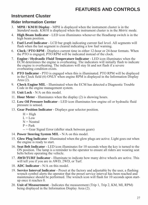
FEATURES AND CONTROLSInstrument ClusterRider Information Center3. MPH / KM/H Display - MPH is displayed when the instrument cluster is in the
Standard mode. KM/H is displayed when the instrument cluster is in the Metric mode. 4. High Beam Indicator - LED icon illuminates whenever the Headlamp switch is in the
high beam position.5. Fuel Level Indicator - LCD bar graph indicating current fuel level. All segments will
flash when the last segment is cleared indicating a low fuel warning.6. Clock / PTO RPM - Displays current time in either 12-hour or 24-hour formats. When
the PTO is engaged, PTO RPM will be indicated instead of the clock.7. Engine / Hydraulic Fluid Temperature Indicator - LED icon illuminates when the
ECM determines the engine is overheating. The indicators will initially flash to indicate the engine is overheating. The indicators will stay lit and not flash if a severe overheating condition exists.
8. PTO Indicator - PTO is engaged when this is illuminated. PTO RPM will be displayed in the Clock field (6) ONLY when engine RPM is displayed in the Information Display Area (2).
9. Check Engine MIL - Illuminated when the ECM has detected a Diagnostic Trouble Code in the engine management system.
10. Unit Lock - N/A on this model.11. Hour Meter - Illuminates when the display (2) is showing hours.12. Low Oil Pressure Indicator - LED icon illuminates low engine oil or hydraulic fluid
pressure is sensed.13. Gear Position Indicator - Displays gear selector position.
H = High L = LowN = NeutralP = Park-- = Gear Signal Error (shifter stuck between gears)
14. Power Steering System MIL - N/A on this model.15. Glow Plug Indicator - Illuminated when the glow plugs are active. Light goes out when
the engine is ready to start.16. Seat Belt Indicator - LED icon illuminates for 10 seconds when the key is turned to the
ON position. The lamp is a reminder to the operator to ensure all riders are wearing seat belts before operating the vehicle.
17. AWD/TURF Indicator - Illuminate to indicate how many drive wheels are active. This will tell you if you are in AWD, 2WD, or Turf.
18. ADC Indicator - N/A on this model.19. Service Interval Indicator - Preset at the factory and adjustable by the user, a flashing
wrench symbol alerts the operator that the preset service interval has been reached and maintenance should be performed. The wrench icon will flash for 10 seconds upon start-up once it reaches 0.
20. Unit of Measurement - Indicates the measurement (Trip 1, Trip 2, KM, MI, RPM) being displayed in the Information Display Area (2).

28
FEATURES AND CONTROLSInstrument ClusterInformation Display AreaThe LCD portion of the instrument cluster is the information display area which displays the following information: odometer, trip meter, RPM, battery voltage, engine temperature, air temperature, engine hours, trouble codes, service interval, and clock.Units of Measurement
To change between Standard and Metric units of measurement, follow these steps:1. Turn the key to the OFF position.2. Press and hold the MODE button while turning the key to
the ON position.3. When the display flashes the distance setting, tap the
MODE button to advance to the desired setting.
4. Press and hold the MODE button to save the setting andadvance to the next display option.
5. Repeat the procedure to change remaining display settings.
OdometerThe odometer records and displays the total distance traveled by the vehicle. The odometer can not be reset.
Trip MeterThe trip meter records the miles traveled by the vehicle on each trip. To reset the trip meter:1. Toggle the MODE button to TRIP 1.2. To reset to 0, push and hold the MODE button until the
distance display changes to 0.Engine Hours1. Engine hours are logged anytime the engine is running.
Total hours can not be reset.
Distance Miles (MPH) Kilometers (KM/H)Temperature Fahrenheit CelsiusTime 12-Hour Clock 24-Hour Clock

29
FEATURES AND CONTROLSInstrument ClusterInformation Display AreaTachometer (RPM)Engine RPM can be displayed digitally.PTO RPM, when engaged, is indicated after the PTO icon.
Engine TemperatureEngine temperature can be displayed in °F or °C. Refer to “Units of Measurement” to change the format.Clock
The clock displays the time in a 12-hour or 24-hour format. Refer to “Units of Measurement” to change the format (Standard 12-hour / Metric 24-hour). To set the clock, follow these steps:1. Toggle the MODE button until the odometer is displayed.2. Press and hold the MODE button until the hour segment
flashes. Release the button.3. With the segment flashing, tap the MODE button to advance to the desired setting.4. Press and hold the MODE button until the next segment flashes. Release the button.5. Repeat steps 3-4 twice to set the 10 minute and 1 minute segments. After completing the
1-minute segment, step 4 will save the new settings and exit the clock mode.Battery Under / Over VoltageThis warning usually indicates that the vehicle is operating at an RPM too low to keep the battery charged. It may also occur when the engine is at idle and a high electrical load is applied (lights, cooling fan or other accessories).Battery Voltage LowIf battery voltage drops below 11 volts, a warning screen will display “Lo” and provide the present battery voltage. If voltage drops below 8.5 volts, LCD back-lighting and icons will turn off.

30
FEATURES AND CONTROLSInstrument ClusterInformation Display AreaProgrammable Service IntervalThe initial factory service interval setting is 50 hours. Each time the engine is started, the engine hours are subtracted from the service interval hours. When the service interval reaches 0, the LCD wrench icon will flash for approximately 10 seconds each time the engine is started. To change the hour setting or reset the function, follow these steps:1. Toggle the MODE button until the wrench icon is displayed in the information area.2. Press and hold the MODE button until the information display area begins to flash.3. Toggle the MODE button to increase the service interval hours in 5 hour increments to a
maximum of 100 hours.4. To turn off the service interval function, toggle the MODE button until “OFF” is displayed.Check HydraulicThis display indicates that hydraulic oil pressure is too low, likely caused by a plugged line or by hydraulic oil temperature being too high. The Oil or Temperature light will illuminate along with this message.

31
FEATURES AND CONTROLSInstrument ClusterInformation Display AreaCheck Engine / Trouble Code DisplayThe diagnostic mode is accessible only when the check engine MIL has been activated.Use the following procedure to display diagnostic trouble codes that were activated during current ignition cycle causing the MIL to illuminate. Diagnostic trouble codes will remain stored in the gauge (even if MIL turns off) until the key is turned off.1. If the trouble codes are not displayed, use the MODE button to toggle until “CK ENG”
displays on the information display area.2. Press and hold the MODE button to enter the diagnostics code menu.3. A set of three numbers will appear in the information area.4. The first number (located far left) can range from 0 to 9. This number represents the total
number of trouble codes present (example: 2 means there are 3 codes present).5. The second number (located top right) can be 2 to 6 digits in length. This number
equates to the suspected area of fault (SPN).6. The third number (located bottom right) can be 1 to 2
digits in length. This number equates to the fault mode (FMI).
7. See your dealer for Diagnostic Trouble Codes.8. If more than one code exists, press the MODE button to
advance to the next trouble code.To exit the diagnostic mode, press and hold the MODE button or turn the ignition key OFF once the codes are recorded.
Horsepower ManagementHorsepower management automatically increases or decreases pressure to the hydrostatic transmission to sustain engine RPM and maintain optimum drive performance.The horsepower management system uses an adjustable spring to determine how much the tractive effort is reduced under load to maintain optimal engine power. The spring is factory adjusted to achieve a balance between maximizing travel performance such as speed and acceleration characteristics and minimizing the amount of operator modulation of the treadle pedal to reduce engine lugging or stalling under loads. The factory adjustment also accounts for the additional engine load from the optional factory installed air conditioning.If less responsive horsepower management is desired (i.e. increased engine lugging during operation) see your dealer for adjustment.

32
OPERATION
Failure to operate the vehicle properly can result in a collision, loss of control, accident or rollover, which may result in serious injury or death. Read and understand all safety warnings outlined in this owner’s manual.
Break-In PeriodThe break-in period for your new vehicle is the first 50 hours of operation. No single action on your part is as important as a proper break-in period. Careful treatment of a new engine will result in more efficient performance and longer life for the engine.New Engine Break-In1. Fill the fuel tank with the recommended fuel. See page 34.2. On the initial engine start-up, allow the engine to idle for approximately 15 minutes.
Check for proper engine oil pressure, diesel fuel leaks, engine oil leaks, coolant leaks, hydraulic leaks and proper operation of the indicators and gauges.
3. During the first hour of operation, vary engine speed and the load on the engine. Short periods of maximum engine speed and load are desirable. Avoid prolonged operation at minimum or maximum engine speeds and loads for the next 4 to 5 hours.
4. During the break-in period, carefully observe the engine oil pressure, engine temperature and hydraulic fluid temperature.
5. Check the engine oil, engine coolant and hydraulic fluid level frequently during the break-in period. Perform regular checks on areas outlined on the daily pre-ride inspection checklist. See page 33.
6. Change both the engine oil and the filter at 50 hours.7. Check fluid levels of transmission and all gearcases after the first 25 hours of operation
and every 100 hours thereafter.
WARNING

33
OPERATIONPre-Ride InspectionFailure to inspect and verify that the vehicle is in safe operating condition before operating increases the risk of an accident. Always inspect the vehicle before each use to make sure it's in safe operating condition.
Item Remarks PageBrake system/pedal travel Ensure proper operation. 24, 96Brake fluid Ensure proper level. 96Front and Rear suspension Inspect, lubricate if necessary. 114Seat Belts Check length of belt for damage, check latches for
proper operation.25
OPS Check condition of OPS and mounting hardware. 25Steering Ensure free operation. 98Tires/wheels/fasteners Inspect condition and pressure. Inspect, ensure fastener
tightness.108
Safety Labels Check for damaged or missing signs (decals). Replace any signs that are damaged or missing.
-
Frame nuts, bolts, fasteners Inspect, ensure tightness. -Fuel and oil Ensure proper levels. 37, 82Coolant level Ensure proper level. 87Coolant hoses Inspect for leaks. -Treadle Pedal Ensure proper operation. 24Indicator lights/switches Ensure operation. 20Air filter, pre-filter Inspect, clean and replace as needed. 90PTO (If Equipped) Inspect splines, guards, shields and hardware, ensure
tightness, replace damaged parts. 45
Brake light/tail lamp /Headlamp
Check operation, apply POLARIS dielectric grease when lamp is replaced.
109
Heater/Air Conditioning Filter Clean and replace filter as needed during heating and cooling season.
101

34
OPERATIONFuel RecommendationsNOTICE: For the best engine performance, to prevent engine damage and to comply with EPA/CARB
warranty requirements, use ONLY the recommended diesel fuels. Use only CLEAN diesel fuel.
POLARIS recommends the following diesel fuels for use in this vehicle:• Low Sulfur• Ultra Low Sulfur #2• #1 Diesel Fuel containing no more than 5% bio-diesel (see page 35)See page 37 for cold weather fuel blend recommendations. For more information about recommended diesel fuels and the consequences of using bio-diesel fuel exceeding 5% bio-diesel, see Additional Technical Fuel Requirements below.Diesel fuel should comply with the following world-wide specifications.
Additional Technical Fuel Requirements• The fuel cetane number should be equal to 45 or higher.• The sulfur content must not exceed 0.5% by volume. Less than 0.5% is preferred.
Especially in the U.S.A. and Canada, Low Sulfur (300 to 500 ppm (mg/kg) or Ultra Low Sulfur fuel should be used.
• Bio-Diesel fuels: see pages 35-36.• NEVER mix kerosene, used engine oil or residual fuels with diesel fuel.• Water and sediment in the fuel should not exceed 0.05% by volume.• Keep the fuel tank and fuel-handling equipment clean at all times.• Poor quality fuel can reduce engine performance and/or cause engine damage.• Fuel additives are not recommended. Some fuel additives may cause poor engine
performance.• Ash content must not exceed 0.01% by volume.• Carbon residue content must not exceed 0.35% by volume. Less than 0.1% is preferred.• Total aromatics content should not exceed 35% by volume. Less than 30% is preferred.• PAH (polycyclic aromatic hydrocarbons) content should be below 10% by volume.• Metal content of Na, Mg, Si and Al should be equal to or lower than 1 mass ppm (test
analysis method JPI-5S-44-95).• Lubricity: Wear mark of WS1.4 should be Max. 0.018 in. (460μm) at HFRR test.
Diesel Fuel Specification LocationASTM D975No. 1D S15, S500No. 2D S15, S500
USA
EN590:96 European UnionISO 8217 DMX InternationalBS 2869-A1 or A2 United KingdomJIS K2204 Grade No. 2 JapanKSM-2610 KoreaGB252 China

35
OPERATIONFuel RecommendationsBio-Diesel FuelsIn Europe and in the United States, as well as some other countries, non-mineral oil based fuel resources such as RME (Rapeseed Methyl Ester) and SOME (Soybean Methyl Ester), collectively known as FAME (Fatty Acid Methyl Esters), are being used as extenders for mineral oil derived diesel fuels.YANMAR approves the use of bio-diesel fuels that do not exceed a blend of 5% (by volume) of FAME with 95% (by volume) of approved mineral oil derived diesel fuel. Such bio-diesel fuels are known in the marketplace as B5 diesel fuels.These B5 diesel fuels must meet certain requirements:1. The bio-fuels must meet the minimum specifications for the country in which they are
used.• In Europe, bio-diesel fuels must comply with the European Standard EN14214.• In the United States, bio-diesel fuels must comply with the American Standard ASTMD-6751.2.
2. Bio-fuels should be purchased only from recognized and authorized diesel fuel suppliers.Precautions and concerns regarding the use of bio-fuels:1. Free methanol in FAME may result in corrosion of aluminum and zinc FIE components.2. Free water in FAME may result in plugging of fuel filters and increased bacterial growth.3. High viscosity at low temperatures may result in fuel delivery problems, injection pump
seizures and poor injection nozzle spray atomization.4. FAME may have adverse effects on some elastomers (seal materials) and may result in
fuel leakage and dilution of the engine lubricating oil.5. Even bio-diesel fuels that comply with a suitable standard as delivered will require
additional care and attention to maintain the quality of the fuel in the equipment or other fuel tanks. It is important to maintain a supply of clean, fresh fuel. Regular flushing of the fuel system and/or fuel storage containers may be necessary.
6. The use of bio-diesel fuels that do not comply with the standards as agreed to by the diesel engine manufacturers and the diesel fuel injection equipment manufacturers, or bio-diesel fuels that have degraded as per the precautions and concerns above, may affect the warranty coverage of your engine.

36
OPERATIONFuel RecommendationsBio-Diesel FuelsB6 To B20 Bio-diesel Fuel Blend UsagesB6 to B20 bio-diesel is not approved for this POLARIS application.Approved EnginesOnly the YANMAR TNM engine series listed below may operate with bio-diesel fuel concentrations up to B5 for POLARIS applicationsNOTICE: Do not exceed bio-diesel fuel blend B5 for this POLARIS application.
• 3TNM72Approved FuelNOTICE: Raw pressed vegetable oils are not considered bio-diesel, and are unacceptable for use as
fuel in any concentration in YANMAR engines.Bio-diesel fuel blends up to B5 must comply with the following standards:• EN14214 (European standard) and/or ASTM D-6751 (American standard).• All applicable engines may operate with bio-diesel fuel up to a maximum B5 (5% bio-
diesel blend) concentration.Operating Conditions with B5 Bio-diesel Fuel BlendsEngine WarrantyDamages, performance or service concerns determined to be caused by the use of bio-diesel fuel not meeting the specifications outlined above are not considered to be defects in material or factory workmanship and are not covered under warranty. The same applies to damages or other concerns induced by not complying with the recommended operating conditions of YANMAR engines with bio-diesel fuel.Handling FuelWARNING! Diesel fuel is flammable and explosive under certain conditions.• NEVER refuel with the engine running.• Always refuel outdoors or in a well ventilated area.• Fill the fuel tank with diesel fuel ONLY. Filling the fuel tank with gasoline may result in a fire and will
damage the engine.• Remove flammable material containers from the box before filling them with fuel. • Do not smoke or allow open flames or sparks in or near the area where refueling is performed or
where fuel is stored.• Wipe up all spills immediately.• Keep sparks, open flames or any other form of ignition (match, cigarette, static electricity source)
well away when refueling.• NEVER remove the fuel cap while the engine is running.• NEVER overfill the fuel tank. Do not fill the tank neck.• If fuel spills on your skin or clothing, immediately wash it off with soap and water and change
clothing.
37
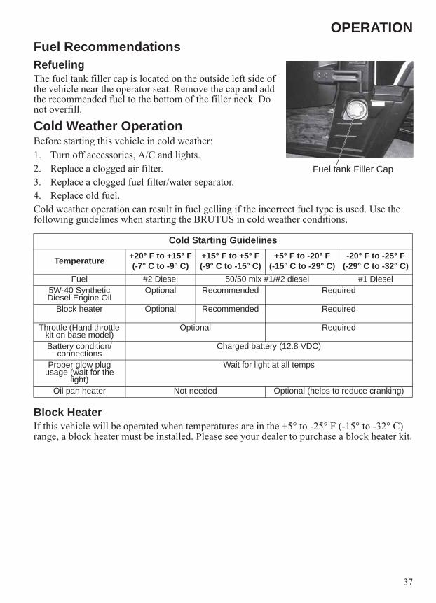
OPERATIONFuel RecommendationsRefuelingThe fuel tank filler cap is located on the outside left side of the vehicle near the operator seat. Remove the cap and add the recommended fuel to the bottom of the filler neck. Do not overfill.
Cold Weather OperationBefore starting this vehicle in cold weather:1. Turn off accessories, A/C and lights.2. Replace a clogged air filter.3. Replace a clogged fuel filter/water separator.4. Replace old fuel.Cold weather operation can result in fuel gelling if the incorrect fuel type is used. Use the following guidelines when starting the BRUTUS in cold weather conditions.
Block HeaterIf this vehicle will be operated when temperatures are in the +5° to -25° F (-15° to -32° C) range, a block heater must be installed. Please see your dealer to purchase a block heater kit.
Cold Starting Guidelines
Temperature +20° F to +15° F(-7° C to -9° C)
+15° F to +5° F(-9° C to -15° C)
+5° F to -20° F(-15° C to -29° C)
-20° F to -25° F(-29° C to -32° C)
Fuel #2 Diesel 50/50 mix #1/#2 diesel #1 Diesel5W-40 Synthetic Diesel Engine Oil
Optional Recommended Required
Block heater Optional Recommended Required
Throttle (Hand throttle kit on base model)
Optional Required
Battery condition/connections
Charged battery (12.8 VDC)
Proper glow plug usage (wait for the
light)
Wait for light at all temps
Oil pan heater Not needed Optional (helps to reduce cranking)
Fuel tank Filler Cap

38
OPERATIONCold Weather OperationBio-Diesel Blended FuelNOTICE: Never use bio-diesel blended fuel containing more than 5% bio-diesel in this vehicle. See
page 35.Bio-diesel blended fuel has unique qualities that should be considered before using it in this vehicle:• Cold weather conditions can lead to plugged fuel system components and hard starting.• Bio-diesel blended fuel is an excellent medium for microbial growth and contamination
which can cause corrosion and plugging of fuel system components.• Use of bio-diesel blended fuel may result in premature failure of fuel system components,
such as plugged fuel filters and deteriorated fuel lines.• Shorter maintenance intervals may be required, such as cleaning the fuel system and
replacing fuel filters and fuel lines.• Using bio-diesel blended fuels containing more than five percent (5%) bio-diesel can
affect engine life and cause deterioration of hoses, tubes, injectors, injector pump and seals.
Use the following guidelines if bio-diesel blended fuel is used:• Never use bio-diesel blended fuel containing more than 5% bio-diesel in this vehicle.• Ensure the fuel tank is as full as possible at all times to prevent moisture from collecting in
the fuel tank.• Ensure that the fuel tank cap is securely tightened.• Clean up any spilled fuel immediately to prevent damage to painted surfaces.• Drain all water from the fuel filter daily before operating the vehicle.• Do not exceed the engine oil change interval. Extended intervals can result in engine
damage.• Before vehicle storage, drain the fuel tank, refill with 100% petroleum diesel fuel, add fuel
stabilizer and run the engine for at least 30 minutes.NOTICE: Bio-diesel blended fuel does not have long term stability and should not be stored for more
than three months.

39
OPERATIONOperating ConditionsNOTICE: Observe the following environmental operating conditions to maintain engine performance
and avoid premature engine wear.• Avoid operating in the presence of chemical gases or fumes.• Avoid operating in a corrosive atmosphere such as salt water spray.• NEVER operate the engine in a floodplain unless proper precautions are taken to avoid
being subject to a flood.• NEVER expose the engine to the rain.• The standard range of ambient temperatures for the normal operation of YANMAR
engines is from +5° F (-15° C) to +104° F (+40° C).• If the ambient temperature exceeds +104° F (+40° C), the engine may overheat and cause
the engine oil to break down.• If the ambient temperature is between +5° F (-15° C) and -25° F (-32° C), POLARIS
recommends the use of a block heater.
Starting the EngineNOTICE: NEVER use an engine starting aid such as ether. Engine
damage will result.Before operating this vehicle in cold weather, review the cold weather operation information beginning on page 37. Always wait for the glow plug indicator light to turn off before cranking the engine.Tip: Engine will not start unless: Gear selector is in Park, Neutral, or
treadle pedal is in neutral and PTO (if equipped) is OFF.1. Always start the engine outdoors or in a well-ventilated area.2. Sit in the driver's seat and fasten the seat belt. 3. Apply the brakes.4. Put the gear selector lever in the Park position.5. Turn the ignition switch to the ON position and wait for the glow plug indicator light to
turn off before cranking the engine.6. Turn the ignition switch past the ON position to START. Engage the starter for a
maximum of five seconds. Release the key when the engine starts.7. If the engine does not start within five seconds, release the ignition switch and wait five
seconds. Repeat steps 5 and 6 until the engine starts.8. Allow the engine to warm to operating temperature. (For Models HD and HDPTO; Vary
the engine RPM slightly with the engine speed control lever to aid in warm up until the engine idles smoothly.)
NOTICE: Operating the vehicle immediately after starting could cause engine and hydraulic component damage. Allow the engine to warm up for several minutes before operating the vehicle.
START HELP

40
OPERATIONStopping the EngineFor maximum engine life, allow the engine to idle, without load, for 5 minutes. This will allow the engine components that operate at high temperatures, such as the exhaust system, to cool slightly before the engine is shut down.1. Press the brake pedal until the utility vehicle comes to a complete stop.2. HD and HDPTO models only: Lower the attachment arm and put the attachment flat on
the ground.3. Move the gear selector lever to Park.4. HD and HDPTO models only: Move the engine speed control lever to low idle.
Disengage the PTO and make sure all rotating components are completely stopped.5. Turn the engine off and remove the key to prevent unauthorized use.NOTICE: A rolling vehicle can cause serious injury. Always place the gear selector lever in PARK
before stopping the engine.
Braking1. Release the treadle pedal completely.2. Press the brake pedal evenly and firmly.3. Practice starting and stopping (using the brakes) until you're familiar with the controls.Tip: When the treadle pedal is released, the vehicle hydraulic system will gradually slow the vehicle to
a stop. Use the brake pedal for faster stopping.
Driving Procedure1. Wear eye protection.2. Perform the pre-ride inspection. See page 33.3. Sit in the driver's seat and fasten the seat belt.4. Start the engine and allow it to warm up.5. HD Model: Raise the attachment arm. See page
42.6. Apply the service brakes and shift the
transmission into gear.7. Check your surroundings and determine your
path of travel.8. Keeping both hands on the steering wheel,
slowly release the brakes and depress the treadle pedal with your right foot to begin driving. (Press the toe of the treadle pedal for forward travel, press the heel of the treadle pedal for backward travel.)
9. Drive slowly. Practice maneuvering and using the treadle pedal and brakes on level surfaces.
Tip: Allow the utility vehicle to come to a stop before changing directions with the treadle pedal.10. Do not carry a passenger until you have at least two hours of driving experience with this
vehicle.

41
OPERATIONDriving with a Passenger1. Perform the pre-ride inspection. See page 33.2. Make sure all passengers are at least 12 years of age and tall enough to comfortably and
safely sit in a passenger seat with the seat belt secured, put both feet on the floor and grasp the hand hold.
3. Make sure all passengers are wearing eye protection.4. Make sure all passengers secure their seat belt.5. Do not carry more than the recommended number of passengers for your vehicle. Allow
a passenger to ride only in a passenger seat.6. Slow down. Always travel at a speed appropriate for your skills, your passengers’ skills,
and operating conditions. Avoid unexpected or aggressive maneuvers that could cause discomfort or injury to a passenger.
7. Vehicle handling may change with a passenger and/or cargo on board. Allow more time and distance for braking.
8. Always follow all operating guidelines as outlined on safety labels and in this manual.

42
OPERATIONHydraulic Controls (Models HD and HDPTO)Joystick OperationThe utility vehicle engine must be running for the hydraulic system to be activated.1. Start the engine. See page 39.2. Allow the hydraulic system to warm to operating temperature.The utility vehicle has both a joystick lockout switch and a tilt lockout switch. When operating PTO driven attachments, the tilt lockout switch will automatically activate. Using the attachment with the tilt locked out will limit the possibility of tilting the attachment while the PTO shaft is turning and putting stress on the PTO driveline u-joints.Tip: Before engaging the PTO system, tilt the attachment to the desired operating position. See your
attachment Owner’s Manual for detailed information.Joystick Lockout: Press the front of the attachment joystick lockout switch to enable the joystick lockout feature. All functions of the joystick will be locked out.Tilt Lockout: Press the front of the attachment tilt lockout switch to lock out the joystick tilt function.Attachment Arm OperationMovement of the joystick controls the hydraulic cylinders for the lift and tilt functions.Pull the joystick backward to raise the attachment arm.Push the joystick forward to lower the attachment arm.Attachment Arm Float Position Move the joystick fully forward until the joystick locks in the float position.Use the float position of the attachment arm to level loose material ONLY while driving backward.Pull the joystick backward to raise the attachment arm and release from the float position.Tilt OperationMove the joystick to the right to tilt the bucket forward. Move the joystick left to tilt the bucket backward.
Tilt Forward PositionTilt Backward Position
Joystick
Tilt Lockout Switch
Joystick Lockout Switch
To Raise the Attachment Arm
To Lower the Attachment Arm
Float Position

43
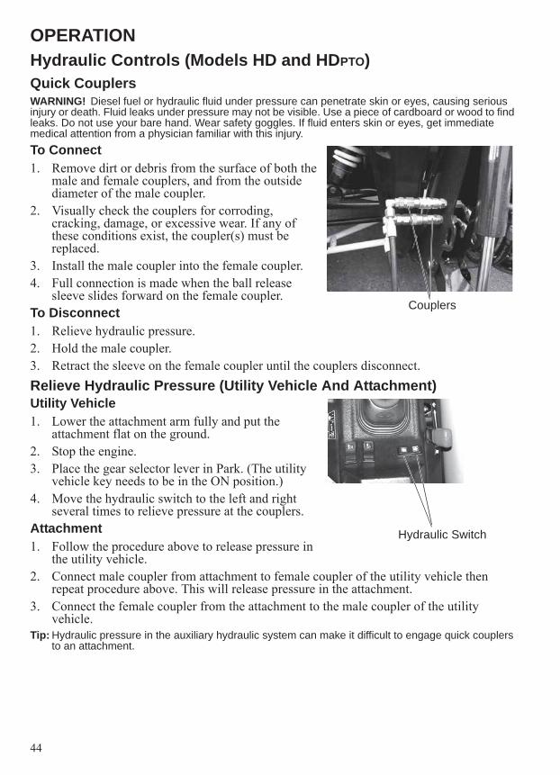
OPERATIONHydraulic Controls (Models HD and HDPTO)Front Auxiliary Hydraulic OperationWARNING! Diesel fuel or hydraulic fluid under pressure can penetrate skin or eyes, causing serious injury or death. Fluid leaks under pressure may not be visible. Use a piece of cardboard or wood to find leaks. Do not use your bare hand. Wear safety goggles. If fluid enters skin or eyes, get immediate medical attention from a physician familiar with this injury.The utility vehicle engine must be running for the auxiliary hydraulic system to be activated.1. Press the left side (1) of the auxiliary hydraulic switch to pressurize the female coupler.2. Press the right side (2) of the auxiliary hydraulic switch to pressurize the male coupler.3. See your attachment Owner’s Manual for detailed information.
Couplers 1 2
44
OPERATIONHydraulic Controls (Models HD and HDPTO)Quick CouplersWARNING! Diesel fuel or hydraulic fluid under pressure can penetrate skin or eyes, causing serious injury or death. Fluid leaks under pressure may not be visible. Use a piece of cardboard or wood to find leaks. Do not use your bare hand. Wear safety goggles. If fluid enters skin or eyes, get immediate medical attention from a physician familiar with this injury.To Connect1. Remove dirt or debris from the surface of both the
male and female couplers, and from the outside diameter of the male coupler.
2. Visually check the couplers for corroding, cracking, damage, or excessive wear. If any of these conditions exist, the coupler(s) must be replaced.
3. Install the male coupler into the female coupler. 4. Full connection is made when the ball release
sleeve slides forward on the female coupler.To Disconnect1. Relieve hydraulic pressure. 2. Hold the male coupler. 3. Retract the sleeve on the female coupler until the couplers disconnect.Relieve Hydraulic Pressure (Utility Vehicle And Attachment)Utility Vehicle1. Lower the attachment arm fully and put the
attachment flat on the ground. 2. Stop the engine. 3. Place the gear selector lever in Park. (The utility
vehicle key needs to be in the ON position.)4. Move the hydraulic switch to the left and right
several times to relieve pressure at the couplers.Attachment1. Follow the procedure above to release pressure in
the utility vehicle.2. Connect male coupler from attachment to female coupler of the utility vehicle then
repeat procedure above. This will release pressure in the attachment.3. Connect the female coupler from the attachment to the male coupler of the utility
vehicle.Tip: Hydraulic pressure in the auxiliary hydraulic system can make it difficult to engage quick couplers
to an attachment.
Couplers
Hydraulic Switch

45
OPERATIONPower Take-Off (PTO) (Model HDPTO)The front PTO is standard equipment on the HDPTO model only.The PTO must be in the disengaged (OFF) position before the engine can be started.The PTO has a rated speed of 2000 RPM.WARNING!• Do Not exceed the rated attachment PTO speed.• Stay clear of rotating driveline• Keep bystanders away.• Keep hands, feet, clothing and long hair away.• Keep PTO shields and guards in place.• Disengage PTO, put gear selector in PARK, stop the
engine and make sure all rotating components are stopped before exiting utility vehicle.
• Do Not service the utility vehicle or attachment with the PTO engaged.
• Do Not service the attachment in a raised position unless properly blocked and all rotating components stopped.
• Disengage PTO for road travel.
Engaging PTOTip: Do not engage the PTO system at higher engine RPM
with the attachment under load. Always engage the PTO system at a lower engine RPM and with the attachment under a no load condition.
1. The operator must be in the operator seat to engage the PTO system. If the operator exits the machine with the PTO engaged, the PTO will shut off.
2. Reduce the engine speed.3. Press the center button of the PTO switch and then
pull up on the knob to engage the PTO.4. The light in the dash will illuminate and the PTO
shaft will start rotating. The PTO RPM will be displayed.
5. Increase the engine speed to the desired RPM specified for your attachment. See your attachment Owner’s Manual for the correct PTO RPM.
Disengaging PTO1. Reduce the engine speed to low idle.2. Press down on the PTO switch to the disengaged (OFF) position. The light in the dash
will turn OFF and the PTO shaft will stop rotating.WARNING! Avoid Injury Or Death• Keep PTO shield and all guards in place.• Keep away from moving parts.• Keep bystanders away.• Do NOT exceed 2000 PTO RPM.
PTO Switch
PTO Light
PTO RPM

46
OPERATIONAttachments (Models HD and HDPTO)Choosing The Correct AttachmentWARNING! Avoid Injury or Death. Never use attachments or buckets which are not approved by POLARIS. Buckets and attachments for safe loads of specific densities are approved for each model. Unapproved attachments can cause injury or death.Tip: Any damage caused by the use of non-approved attachments is not covered by warranty.The dealer can identify, for the utility vehicle, the attachments and buckets approved by POLARIS. The buckets and attachments are approved for attachment arm rated capacity and for secure fastening to the PRO-TACH.The attachment arm rated capacity is determined by using a standard bucket and material of normal density, such as dirt or dry gravel. If very dense material is loaded, the volume must be reduced to prevent overloading.Exceeding the arm rated capacity could result in:• Difficult steering• Longer stopping distance• Faster tire wear• Loss of stability• Reduced utility vehicle lifeUse the correct size bucket for the type and density of material being handled. For safe handling of materials and avoiding vehicle damage, the attachment (or bucket) should handle a full load without going over the attachment arm rated capacity for the utility vehicle.Choosing The Correct Attachment If a pallet fork attachment is used, the load center moves forward and reduces the load capacity.The maximum load to be carried when using a pallet fork is shown on a label located on the pallet fork frame.See your dealer for more information about pallet fork inspection, maintenance and replacement. See your dealer for attachment arm rated capacity when using a pallet fork and for other available attachments.
Label

47
OPERATIONAttachments (Models HD and HDPTO)Installing And Removing AttachmentsThe PRO-TACH attachment system is used for fast changing of buckets and other attachments. See the appropriate Attachment Owner’s Manual to install other attachments.Installing:1. Remove the two retainers and pins from the
storage position.2. Start the engine. See page 39. Move the gear
selector lever to LOW.3. Lower the attachment arm and tilt the attachment
interface forward.
4. Slowly drive forward until the front edge of the attachment interface is completely under the top lip of the attachment.
5. Tilt the attachment interface backward until the attachment is slightly off the ground.
6. Move the gear selector lever to PARK and stop the engine. See page 40.
7. Install the two pins and retainers (both sides).8. Connect the auxiliary hydraulic hoses (if
equipped). See page 44.9. Connect the PTO driveline (if equipped). See page
49.
Pins Retainers
Lip of the attachment
Pin Retainer

48
OPERATIONAttachments (Models HD and HDPTO)Installing And Removing AttachmentsRemovingTip: In muddy conditions or to prevent the attachment from freezing to the ground, put the attachment
on planks or blocks before removing the attachment from the vehicle.1. Lower the attachment arm and put the attachment
flat on the ground.2. Move the gear selector lever to PARK and stop the
engine. See page 40.3. If the attachment is hydraulically controlled, (snow
blade, etc.), relieve the hydraulic pressure at the quick couplers. See page 44.
4. Disconnect the auxiliary hydraulic quick couplers. (if equipped). See page 44.
5. Disconnect the PTO driveline (if equipped). See page 45.
6. Remove the two retainers and pins (both side).7. Install the two pins and retainers into the storage
position.8. Start the engine. See page 39. Move the gear
selector lever to LOW.9. Be sure the attachment is fully lowered and the
attachment is flat on the ground.10. Tilt the attachment interface forward. Move
backward, away from the attachment.WARNING! Avoid injury or death. Before you leave the operators seat:• Park on flat level ground.• Lower the attachment arm, put the attachment flat on the
ground.• Press the brake pedal and move the gear selector lever to
PARK.• Disengage the PTO (if equipped) and make sure all
rotating components are completely stopped.• Stop the engine and remove the key.
Pin
Pins
Retainer
Retainers

49
OPERATIONPower Take-Off (PTO) (Models HDPTO)Installing And Removing The PTOThe BRUTUS Model HDPTO is factory equipped with a PTO.The PTO has a rated speed of 2000 RPM.WARNING!• Do Not exceed the rated attachment PTO speed.• Stay clear of rotating driveline.• Keep bystanders away.• Keep hands, feet, clothing and long hair away.• Keep PTO shields and guards in place.• Disengage PTO, put gear selector in PARK, stop the engine and make sure all rotating components
are stopped before exiting utility vehicle.• Do Not service the utility vehicle or attachment with the PTO engaged.• Do Not service the attachment in a raised position unless properly blocked and all rotating
components stopped.• Disengage PTO for road travel.
Installing1. Install the attachment to the utility vehicle. See page 46.2. Stop the engine and exit the vehicle. See page 40.3. Make sure the PTO driveline and all rotating components have come to a complete stop
before exiting the vehicle.NOTICE: Avoid PTO Driveline Damage• Do not modify the attachment arm or PTO driveline.• Make sure PTO driveline is the correct length and that the u-joints are in the correct phase.• Use only approved PTO drivelines designated for the attachment and never use unapproved
attachments.WARNING! Rotating Parts Can Cause Serious Injury Or Death• Disengage the PTO, put the gear selector in PARK, stop the engine and make sure all rotating
components are completely stopped before connecting, disconnecting, adjusting or cleaning any PTO driven equipment.
• Always keep PTO shields and all guards in place when using the PTO driven equipment.• Disengage PTO for road travel.• Keep hands, feet, clothing and long hair away.WARNING! Driveline Entanglement Or Overspeeding PTO Can Cause Serious Injury Or Death• Do Not install an adapter between the utility vehicle PTO shaft and the attachment PTO driveline.• An adapter can extend the driveline universal joint and connecting yoke beyond the PTO shields.• An adapter can overspeed the attachment PTO causing driveline or attachment damage.

50
OPERATIONPower take-Off (PTO) (Models HDPTO)Installing And Removing The PTOEach attachment has a specific length PTO drive shaft that is affixed to the attachment. Do not intermix or replace drive shafts or components between different attachment types.Connect the PTO driveline to the PTO shaft of the utility vehicle. Make sure it is securely connected by pushing and pulling on the driveline. See your attachment Owner’s Manual for additional information.Tip: The PTO driveline must have a means to retain it to the
PTO shaft on both the utility vehicle and the attachment.WARNING! Avoid Injury or Death• Keep PTO shields and guards in place.• Keep away from moving parts.• Keep bystanders away.• Do Not exceed 2000 PTO RPM.
Removing1. Stop the engine and exit the utility vehicle. See
page 40.2. Make sure the PTO driveline and all rotating
components have come to a complete stop before exiting the utility vehicle.
3. Disconnect the PTO driveline from the utility vehicle. See your attachment Owner’s Manual for additional information.
WARNING! Rotating Parts Can Cause Serious Injury Or Death• Disengage the PTO, put the gear selector in PARK, stop the engine and make sure all rotating com-
ponents are completely stopped before connecting, disconnecting, adjusting or cleaning any PTO driven equipment.
• Always keep PTO shields and all guards in place when using the PTO driven equipment.• Disengage PTO for road travel.• Keep hands, feet, clothing and long hair away.
PTO Driveline

51
OPERATIONDriving UphillWhenever traveling uphill, follow these precautions:1. Always travel straight uphill.2. Avoid steep hills (15° maximum). For model HD
and HDPTO: Keep the heavy end of the vehicle uphill. See page 58.
3. Keep both feet on the floor.4. Always check the terrain carefully before
ascending any hill.5. Never climb hills with excessively slippery or
loose surfaces.6. Proceed at a steady rate of speed. Never move the
treadle pedal or change direction of travel suddenly. 7. Never go over the crest of a hill at high speed. An obstacle, a sharp drop, or another
vehicle or person could be on the other side of the hill.
Stalling While Climbing A HillStalling or rolling backwards while climbing a hill could cause rollover. Always maintain a steady speed when climbing hills.If All Forward Speed Is Lost:1. Apply the brakes.2. Place the transmission in neutral and slowly allow the vehicle to roll straight downhill
while applying light brake pressure to control speed.If you Begin Rolling Downhill:1. Never apply engine power.2. Decelerate using the treadle pedal and apply the brake gradually until the vehicle is fully
stopped.3. Place the transmission in neutral and slowly allow the vehicle to roll straight downhill
while applying light brake pressure to control speed.
Driving on a Sidehill (Sidehilling)Driving on a sidehill is not recommended. Improper procedure could cause loss of control or rollover. Avoid crossing the side of any hill unless absolutely necessary.If crossing a sidehill is unavoidable, follow these precautions:1. Slow down.2. Exercise extreme caution.3. Avoid crossing the side of a steep hill (15° maximum).
15° maximum

52
OPERATIONDriving DownhillWhen driving downhill, follow these precautions:1. Avoid steep hills (15° maximum).2. Drive straight downhill. Avoid descending a hill at
an angle, which would cause the vehicle to lean sharply to one side. Travel straight downhill when possible. For model HD and HDPTO: Keep the heavy end of the vehicle uphill. See page 58.
3. Slow down.4. Apply the brakes slightly to aid in slowing.
Driving on Slippery Surfaces
Skidding or sliding can cause loss of control or rollover (if tires regain traction unexpectedly). When operating on slippery surfaces such as ice or loose gravel, reduce speed and use extra caution to reduce the chance of skidding or sliding out of control. Do not operate on excessively slippery surfaces.Whenever riding on slippery surfaces such as wet trails or loose gravel, or during freezing weather, follow these precautions:1. Do not operate on excessively rough, slippery or loose terrain.2. Slow down before entering slippery areas.3. Maintain a high level of alertness, reading the trail and avoiding quick, sharp turns,
which can cause skids.4. Engage all-wheel drive before wheels begin to lose traction.NOTICE: Severe damage to the drive train may occur if the AWD is engaged while the wheels are
spinning. Always allow the wheels to stop spinning before engaging AWD.5. Correct a skid by turning the steering wheel in the direction of the skid. Never apply the
brakes during a skid.
15° maximum
WARNING
Sideways skid
Turn in direction of
skid

53
OPERATIONDriving Over ObstaclesFollow these precautions when operating over obstacles:1. Always check for obstacles before operating in a
new area.2. Look ahead and learn to read the terrain. Be
constantly alert for hazards such as logs, rocks and low hanging branches.
3. Travel slowly and use extra caution when operating on unfamiliar terrain. Not all obstacles are immediately visible.
Tip: For model HDPTO: When driving over objects (example: a curb), always drive at a slight angle and at slow speed to allow one wheel at a time to go over the object. This will allow maximum ground clearance for the utility vehicle and avoid PTO shaft damage.
Driving in ReverseFollow these precautions when operating in reverse:1. Always check for obstacles or people behind the
vehicle. Always inspect left and right fields of vision before backing. Always look in the direction of travel.
2. Always avoid backing downhill.3. Back slowly.4. Decelerate using the treadle pedal and apply the
brakes lightly for stopping.5. Avoid turning at sharp angles.6. Never move the treadle pedal suddenly.
Parking on an InclineAvoid parking on an incline if possible. If it's unavoidable, follow these precautions:1. Apply the brakes. 2. Place the transmission in PARK.3. Turn the engine off.4. Block the rear wheels on the downhill side.
15° maximum
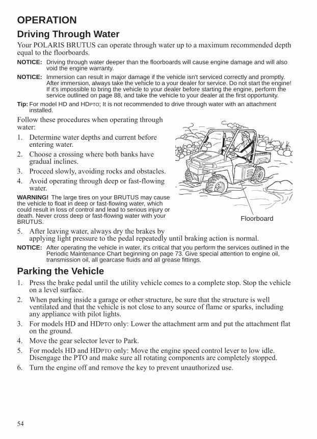
54
OPERATIONDriving Through WaterYour POLARIS BRUTUS can operate through water up to a maximum recommended depth equal to the floorboards. NOTICE: Driving through water deeper than the floorboards will cause engine damage and will also
void the engine warranty.NOTICE: Immersion can result in major damage if the vehicle isn't serviced correctly and promptly.
After immersion, always take the vehicle to a your dealer for service. Do not start the engine! If it's impossible to bring the vehicle to your dealer before starting the engine, perform the service outlined on page 88, and take the vehicle to your dealer at the first opportunity.
Tip: For model HD and HDPTO; It is not recommended to drive through water with an attachment installed.
Follow these procedures when operating through water:1. Determine water depths and current before
entering water.2. Choose a crossing where both banks have
gradual inclines.3. Proceed slowly, avoiding rocks and obstacles.4. Avoid operating through deep or fast-flowing
water.WARNING! The large tires on your BRUTUS may cause the vehicle to float in deep or fast-flowing water, which could result in loss of control and lead to serious injury or death. Never cross deep or fast-flowing water with your BRUTUS.5. After leaving water, always dry the brakes by
applying light pressure to the pedal repeatedly until braking action is normal.NOTICE: After operating the vehicle in water, it's critical that you perform the services outlined in the
Periodic Maintenance Chart beginning on page 73. Give special attention to engine oil, transmission oil, all gearcase fluids and all grease fittings.
Parking the Vehicle1. Press the brake pedal until the utility vehicle comes to a complete stop. Stop the vehicle
on a level surface.2. When parking inside a garage or other structure, be sure that the structure is well
ventilated and that the vehicle is not close to any source of flame or sparks, including any appliance with pilot lights.
3. For models HD and HDPTO only: Lower the attachment arm and put the attachment flat on the ground.
4. Move the gear selector lever to Park.5. For models HD and HDPTO only: Move the engine speed control lever to low idle.
Disengage the PTO and make sure all rotating components are completely stopped.6. Turn the engine off and remove the key to prevent unauthorized use.
Floorboard
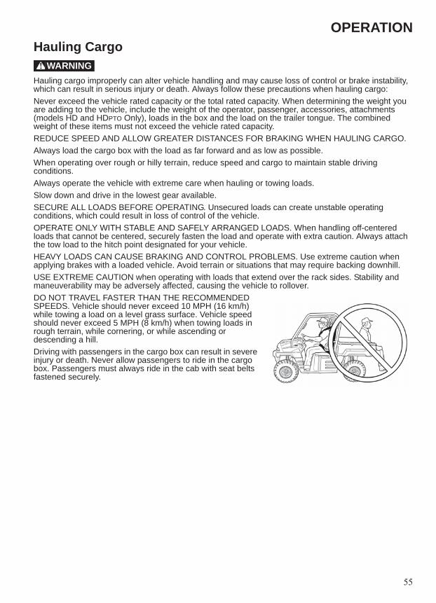
55
OPERATIONHauling Cargo
Hauling cargo improperly can alter vehicle handling and may cause loss of control or brake instability, which can result in serious injury or death. Always follow these precautions when hauling cargo:Never exceed the vehicle rated capacity or the total rated capacity. When determining the weight you are adding to the vehicle, include the weight of the operator, passenger, accessories, attachments (models HD and HDPTO Only), loads in the box and the load on the trailer tongue. The combined weight of these items must not exceed the vehicle rated capacity.REDUCE SPEED AND ALLOW GREATER DISTANCES FOR BRAKING WHEN HAULING CARGO.Always load the cargo box with the load as far forward and as low as possible.When operating over rough or hilly terrain, reduce speed and cargo to maintain stable driving conditions.Always operate the vehicle with extreme care when hauling or towing loads.Slow down and drive in the lowest gear available.SECURE ALL LOADS BEFORE OPERATING. Unsecured loads can create unstable operating conditions, which could result in loss of control of the vehicle.OPERATE ONLY WITH STABLE AND SAFELY ARRANGED LOADS. When handling off-centered loads that cannot be centered, securely fasten the load and operate with extra caution. Always attach the tow load to the hitch point designated for your vehicle.HEAVY LOADS CAN CAUSE BRAKING AND CONTROL PROBLEMS. Use extreme caution when applying brakes with a loaded vehicle. Avoid terrain or situations that may require backing downhill.USE EXTREME CAUTION when operating with loads that extend over the rack sides. Stability and maneuverability may be adversely affected, causing the vehicle to rollover.DO NOT TRAVEL FASTER THAN THE RECOMMENDED SPEEDS. Vehicle should never exceed 10 MPH (16 km/h) while towing a load on a level grass surface. Vehicle speed should never exceed 5 MPH (8 km/h) when towing loads in rough terrain, while cornering, or while ascending or descending a hill.Driving with passengers in the cargo box can result in severe injury or death. Never allow passengers to ride in the cargo box. Passengers must always ride in the cab with seat belts fastened securely.
WARNING

56
OPERATIONHauling CargoThe BRUTUS has been designed to carry or tow specific capacities. Always read and understand the load distribution warnings listed on the warning labels. The total load (operator, passenger, attachments, accessories, cargo and weight on hitch) must not exceed the maximum weight capacity of the vehicle. Never exceed the following capacities.
A - Attachment Arm Rated Capacity * = 500 lbs. (225 kg) MaximumB - Weight of Occupant(s) = 500 lbs. (225 kg) MaximumC - Maximum Cargo Box Load = 1250 lbs. (567 kg)D - Maximum Trailer Hitch Tongue Weight = 150 lbs. (68 kg)E - Tow Weight (Level Ground) = 2000 lbs. (907 kg) (includes weight of trailer)Vehicle Rated Capacity = A plus B plus C plus D = (BRUTUS and BRUTUS HDPTO) 1750 lbs. (794 kg) / (BRUTUS HD) 2000 lbs. (907 kg) Maximum* Attachment Arm Rated Capacity is determined by using the standard bucket and material of normal density, such as dirt or dry gravel. If other attachments such as pallet forks are used, the load is moved forward and the attachment arm capacity is reduced. If very dense material is loaded, the volume must be reduced.
Model Attachment Arm Rate Capacity
Passenger Compartment
Maximum Cargo Box
Weight Capacity
Maximum Trailer Hitch
Tongue Weight
Vehicle Rated
CapacityMaximum Weight
Maximum Occupants
BRUTUS Not Applicable 500 lbs.(225 kg)
3 1250 lbs.(567 kg)
150 lbs.(68 kg)
1750 lbs.(794 kg)
BRUTUS HD 500 lbs.(225 kg)
500 lbs.(225 kg)
2 1250 lbs.(567 kg)
150 lbs.(68 kg)
2000 lbs.(907 kg)
BRUTUS HDPTO 500 lbs.(225 kg)
500 lbs.(225 kg)
2 1250 lbs.(567 kg)
150 lbs.(68 kg)
1750 lbs.(794 kg)
A
B
C
D E

57
OPERATIONTowing LoadsTowing improperly can alter vehicle handling and may cause loss of control or brake instability. Always follow these precautions when towing:1. Never load more than 150 lbs. (68 kg) tongue weight on the towing bracket.2. Use low range. Do not operate the vehicle faster than 10 MPH (16 km/h) when towing..
Towing a trailer increases braking distance.3. Do not tow more than the recommended weight for the vehicle. See the towing capacity
chart on previous page.4. Attach a trailer to the trailer hitch bracket only. Do not attach a trailer to any other
location or you may lose control of the vehicle.5. Never tow a trailer on a grade steeper than 15°.
Dumping the Cargo Box1. Select a level site to dump the cargo box. Do not
attempt to dump or unload the vehicle while parked on an incline.
2. Apply the brakes. 3. Place the transmission in gear.4. Engage the park brake.5. Dismount the vehicle.6. Ensure that the cargo is positioned evenly or
toward the front of the cargo box.7. Release the tailgate by pulling up on the tailgate
latch.WARNING! If the weight distribution on the box is located toward the rear of the box when the release lever is pulled forward, the box may dump unexpectedly and cause serious injury to the operator or bystanders. Never operate the dump lever without ensuring that the load is positioned evenly or at the front of the box.8. Stand clear and pull up on the cargo box release
lever. Lift the front of the cargo box to dump the cargo. If equipped with power lift assist, press and hold the top of the lift switch to raise the cargo box. Release the switch after cargo dumps or when the box reaches the fully elevated position, indicated by a ratcheting sound.
9. Lower the cargo box and push down securely to latch. If equipped with power lift assist, press and hold the bottom of the lift switch to lower the cargo box. Release the switch when the box is fully seated on the frame, indicated by a ratcheting sound.
WARNING! Operating the vehicle while the cargo box is raised could result in severe injury. The box could close unexpectedly and cause injury to the driver or passenger. The rear tires will also catch the rear of a raised box, damaging the vehicle and creating hazardous driving conditions. Never operate this vehicle with the cargo box in the raised position.
Release Lever
Lift Switch

58
OPERATIONOperating With A Full Bucket And Empty Cargo Box
With a loaded bucket and an empty cargo box, go up or down the slope with the heavy end toward the top of the slope. Look in the direction of travel.
Operating With An Empty Bucket And Loaded Cargo Box
With an empty bucket and a loaded cargo box, go up or down the slope with the heavy end toward the top of the slope. Look in the direction of travel.WARNING! Vehicle Tipping Or Rollover Can Cause Serious Injury or Death
• Keep the attachment arm as low as possible.• Turn on level ground. Slow down when turning.• Go up and down slopes, not across them.• Keep the heavy end of the vehicle uphill.• Do not exceed vehicle load capacity.• Check for adequate traction.
Raise the bucket only high enough to avoid obstructions on rough ground.When both are empty or when both are loaded, the front and rear of the vehicle are close to the same weight. You can either move forward or backward up and down the slope.
Going Up Slope Going Down Slope
Loaded Bucket And Empty Cargo Box
Loaded Bucket And Empty Cargo Box
Going Up Slope Going Down Slope

59
OPERATIONFilling And Emptying The BucketFilling1. Lower the attachment arm all the way (A) and
tilt the bucket forward (D) until the cutting edge is on the ground.
2. Drive slowly forward to push the bucket slightly into the material.
3. Raise the attachment arm (B) and tilt the bucket backward (C).
WARNING! Load, unload and turn on flat level ground. Do not exceed vehicle load capacity shown on sign (decal) in cargo box. Failure to obey warnings can cause vehicle rollover and can cause serious injury or death.4. Drive backward away from the material.
Emptying1. Keep the bucket low when moving to the area
where you want to dump the material.2. Move the machine slowly to the dump area3. While raising the attachment arm (B), tilt the
bucket forward (D) to keep it level and help prevent material from falling off the back of the bucket.
4. Tilt the bucket all the way forward (D) to empty the bucket.
A
B
C D
A
B
C D
A
B
C D

60
OPERATIONLeveling The Ground Using Float1. Raise the attachment arm (B) and tilt the bucket
forward (D).2. Push the joystick all the way forward (AA) to
activate float.NOTICE: Never drive forward when the attachment arm
is in the float position.3. Drive backward to level loose material.4. Pull the joystick backward (B) to unlock the
attachment arm from the float position.
Backfilling1. Lower the attachment arm (A) and put the
cutting edge of the bucket on the ground (D). Drive forward to the edge of the hole to push the material into the hole.
2. Tilt the bucket forward (D) as soon as it is past the edge of the hole.
3. If necessary, raise the lift arms to empty the bucket.
A
B
C D
AA
A
B
C D

61
OPERATIONAll Wheel Drive (AWD)Engaging AWDPress the top of the rocker switch to engage All Wheel Drive (AWD). The illuminated amber AWD switch indicates that the vehicle is in AWD.When the AWD switch is on, the front wheels will automatically engage any time the rear wheels lose traction. When the rear wheels regain traction, the front wheels will automatically disengage. There is no limit to the length of time the vehicle may remain in AWD.Tip: The AWD switch may be turned on or off while the vehicle is
moving. Engage the AWD before getting into conditions where front wheel drive may be needed. If the rear wheels are spinning, release the treadle pedal before switching to AWD.NOTICE: Switching to AWD while the rear wheels are spinning may cause severe drive shaft and
clutch damage. Always switch to AWD while the rear wheels have traction or are at rest.
Disengaging AWDMove the AWD switch to the center or bottom position to disengage AWD. If the switch is turned off while the front hubs are driving, they will not release until the rear wheels regain traction.In some situations, the front gearcase may remain locked after turning the AWD switch off. If this occurs, you may notice increased steering effort and some vehicle speed restriction. Perform the following procedure to unlock the front gearcase.1. Stop the vehicle. Operate in reverse for at least 10 feet (3 m).2. Stop completely. Shift into low gear and drive forward.3. If the front gearcase remains locked after following these instructions, see your dealer
for service.Locking the DifferentialNOTICE: Damage to the differential can occur if it is engaged while
the vehicle is traveling at high speeds or while the rear wheels are spinning. Slow the vehicle to nearly stopped before engaging the differential.
Locking the differential in slippery or low traction conditions helps improve traction. Move the rocker switch to the center position (2WD) to lock the differential and operate in rear wheel drive.Press the bottom of the switch to unlock the differential and allow the rear drive wheels to operate independently. This mode of operation is well suited to turf driving or whenever aggressive traction is not required.

62
OPERATIONPTO Safety (if equipped)WARNING!• Do Not exceed the rated attachment PTO speed.• Stay clear of rotating driveline.• Keep bystanders away.• Keep hands, feet, clothing and long hair away.• Keep PTO shields and all guards in place.• Disengage PTO, put transmission in Park, stop the engine and make sure all rotating components
are stopped before exiting utility vehicle.• Do NOT service the utility vehicle or implement with the PTO engaged.• Do NOT service the implement in a raised position unless properly blocked and with all rotating
components stopped.• Disengage PTO for road travel.
WARNING! Before you leave the operator’s seat:• Park on flat level ground.• Lower the attachment arm, put the attachment flat on the ground.• Press the brake pedal and move the gear selector lever to PARK.• Disengage the PTO and make sure all rotating components are completely stopped.• Stop the engine and remove the key.
WARNING! Warnings and instructions in this manual and on the machine are for your protection.Failure to follow the warnings and instructions can cause serious injury or death.• Keep all shields in place. Replace damaged or missing shields before operating• Follow warnings and instructions on machine signs (decals). Replace damaged or missing decals.• Do not wear loose or bulky clothing around the PTO or other moving parts.• Keep bystanders away from PTO driven equipment, and never allow children near machines.• Read and understand the manuals for the PTO driven equipment and be aware of safe operating
procedures and hazards that may not be readily apparent.• Always walk around equipment to avoid coming near a turning PTO driveline. Stepping over, leaning
across or crawling under a turning PTO driveline can lead to entanglement.• Do not install an adapter between the machine PTO shaft and the attachment PTO driveline.• Never overspeed the PTO. See attachment Owner’s Manual for correct PTO speed.• Position the machine and attachment correctly to prevent driveline stress and separation.• Use caution when raising PTO driven attachment. Excessive driveline angle can reduce driveline
service life.• Do not engage the PTO system at higher engine RPM with attachment under load. Always engage
the PTO system at a lower engine RPM and with attachment under a no load condition.
WARNING! Driveline Entanglement Or Overspeeding PTO Can Cause Serious Injury Or Death• DO NOT install an adapter between the utility vehicle PTO shaft and the attachment PTO driveline.• An adapter can extend the driveline universal joint and connecting yoke beyond the PTO shields.• An adapter can overspeed the attachment PTO causing driveline or attachment damage.

63
OPERATIONOperating The PTO (HDPTO)The BRUTUS HDPTO utility vehicle is factory equipped with a PTO. The PTO has a rated speed of 2000 RPM.Read and understand the attachment Owner’s Manual and the utility vehicle Owner’s Manual prior to installing or using any attachment.WARNING!• Steering and braking can be affected by the attachment, four wheel drive and the rear differential
lock. Do not exceed the rated lift capacities. • Always carry loads low. Slow down when turning.
Always inspect the utility vehicle and the attachment before use. Inspect for damaged or loose parts, damaged or missing PTO shields and guards.New operators must operate the utility vehicle in an open area without bystanders. Operate the controls until the utility vehicle can be handled at a efficient and safe speed for all conditions of the work area.Check for safe operating speed, safe stopping distances and braking characteristics that may be different with each type of attachment. Know that when attachments are installed, the utility vehicle braking distance increases.Before beginning operation, inspect the work area for unsafe conditions.Look for drop-offs or rough terrain. Have underground utility lines (gas, water, sewer, irrigation, etc.) located and marked.Remove objects or other construction material that could damage the utility vehicle or cause personal injury.Do not engage the PTO system at higher engine RPM with attachment under load. Always engage the PTO system at a lower engine RPM and with attachment under a no load condition.WARNING!• Do NOT exceed the rated attachment PTO speed.• Stay clear of rotating driveline.• Keep bystanders away.• Keep hands, feet, clothing and long hair away.• Keep PTO shields and all guards in place.• Disengage PTO, put transmission in Park, stop the engine and make sure all rotating components
are stopped before exiting utility vehicle.• Do NOT service the utility vehicle or implement with the PTO engaged.• Do NOT service the implement in a raised position unless properly blocked and with all rotating
components stopped.• Disengage PTO for road travel.

64
OPERATIONOperating The PTO (HDPTO)See the attachment Owner’s Manual for the correct operating procedure for your attachment.Install the attachment on the utility vehicle. See pages 47-48.Engaging PTO1. Start the engine. See page 39.2. Reduce the engine speed.Tip: Do not engage the PTO system at higher engine
RPM with the attachment under load. Always engage the PTO system at a lower engine RPM and with the attachment under a no load condition.
3. On the PTO switch, press the center button and then pull up on the knob to engage the PTO.
4. The light in the dash will illuminate and the PTO shaft will start rotating. The PTO shaft RPM will be displayed in the dash.
5. Increase the engine speed to the desired RPM specified for your attachment. See the attachment Owner’s Manual for the correct attachment operating RPM. (With engine RPM at 3600, the PTO shaft will rotate at approximately 2000 RPM. Adjust engine RPM to meet the attachment RPM requirement.)
Tip: The maximum PTO speed for various attachments may vary. See the attachment Owner’s Manual for the maximum speed recommended for your attachment.
Tip: When driving over objects (example: a curb), always drive at a slight angle and at slow speed to allow one wheel at a time to go over the object. This will allow maximum ground clearance for the utility vehicle and avoid PTO shaft damage.
Tip: Do not engage the PTO system at higher engine RPM with the attachment under load. Always engage the PTO system at a lower engine RPM and with the attachment under a no load condition.
WARNING!• Keep PTO shield and all guards in place.• Keep away from moving parts.• Keep bystanders away.• Do NOT exceed 2000 PTO RPM.
PTO Light
PTO Shaft RPM
PTO Switch

65
ATTACHMENT ARMRemoving And Installing (Models HD and HDPTO)When the PRO-TACH attachment system is not being used, it can be removed from the vehicle.Tip: Remove the bucket or attachment before removing the attachment arm from the vehicle.
Removing1. Park the vehicle on a flat level surface.2. Lower the attachment arm fully and tilt the PRO-
TACH fully forward.Tip: In muddy conditions or to prevent the attachment arm
from freezing to the ground, put the attachment arm on planks or blocks before removing the attachment arm from the vehicle.
3. Move the gear selector lever to PARK and stop the engine. See page 40.
WARNING! Avoid Injury. Keep fingers and hands out of pinch points when removing and installing the attachment arm.Tip: When the pin is removed from the tilt cylinder, the
interface will be free to tilt down to the ground. Support the interface while the pin is being removed.
4. Remove the retainer pin and the pin from the rod end of the tilt cylinder and position the interface flat on the ground.
5. Remove the retainer pin and pin from the rod end of the lift cylinder.
6. Start the engine. See page 39. 7. Press the bottom of the joystick lockout switch to
enable the joystick.8. Retract both the lift and tilt cylinders fully.9. Press the top of the joystick lockout switch to
disable the joystick.10. Turn the key to the off position and exit the
vehicle. See page 40.
Pin
Retainer Pin
Retainer Pin
Pin

66
ATTACHMENT ARMRemoving And Installing (Models HD and HDPTO)The PRO-TACH attachment system is used for fast changing of buckets and other attachments. See the appropriate attachment Owner’s Manual to install other attachments.11. Rotate the tilt cylinder up and into the storage position. A heavy tie strap can be used to
secure the cylinder to the grille in the storage position.12. Position the cylinder to the frame and install the
pin and the retainer pin to secure the lift cylinder in the storage position.
Tip: When the pins are removed from the attachment arm, it will be free to tilt down to the ground. Support the attachment arm while the pins are being removed.
13. Remove the two retainer pins and pins and lower the attachment arm fully.
14. Reinstall the pins and the retainer pins into the attachment arm for storage.
Pin Retainer Pin
PinPin Retainer Pin

67
ATTACHMENT ARMRemoving And Installing (Models HD and HDPTO)InstallingWARNING! Avoid Injury. Keep fingers and hands out of pinch points when removing and installing the attachment arm.1. Position the utility vehicle so it is centered in front
of the attachment arm.2. Remove the retainer pins and pins from the
attachment arm (both sides).
3. Raise the attachment arm and position it to the vehicle mounting frame. Install the two pins and retainer pins.
4. Remove the lift cylinder retainer pin and the pin.5. Lower the tilt cylinder down and rest the rod end
on the attachment arm.
PinPin Retainer Pin
Pin Retainer Pin

68
ATTACHMENT ARMRemoving And Installing (Models HD and HDPTO)6. Start the engine. See page 39. Press the bottom of the joystick lockout switch to enable
the joystick.WARNING! Avoid Injury. Keep fingers and hands out of pinch points when removing and installing the attachment arm.7. Extend the lift cylinder fully.8. Extend the tilt cylinder fully.9. Press the top of the joystick lockout switch to
lockout the joystick. Turn the key to the OFF position and exit the utility vehicle.
10. Raise the interface until it is aligned with the rod end of the lift cylinder. Install the pin and retainer pin.
11. Rotate the interface upward until it is aligned with the rod end of the tilt cylinder. Install the pin and retainer pin.
12. Lubricate the attachment arm and the cylinder grease fittings. See page 114.
Retainer Pin
Pin
Pin
Retainer Pin

69
PTO SYSTEMRemoving And Installing PTO Shafts (Models HDPTO)If the utility vehicle will not be used for PTO driven attachments for extended periods of time, it is possible to remove the PTO drive shaft assembly from the PTO clutch. This will prevent damage to the PTO system if the utility vehicle will be used off road or if additional ground clearance is desired. Removing1. Stop the engine. See page 40.2. Make sure the PTO driveline and all rotating components have come to a complete stop
before exiting the utility vehicle.3. Install the utility vehicle on jack stands. See page 107.4. Remove the four bolts and remove the shield.
Bolt Installation Torque: 7-8 ft-lbs (9-10 Nm)
5. Remove the eight bolts and remove the belly pan.Bolt Installation Torque: 7-8 ft-lbs (9-10 Nm)
Bolts
BoltsShield
Bolts
BoltsBelly Pan

70
PTO SYSTEMRemoving And Installing PTO Shafts (Models HDPTO)6. Remove the four bolts and nuts and remove the
guard.Bolt Installation Torque: 32-35 ft-lbs (43-47 Nm)
7. Remove the four bolts and nuts and remove the PTO shaft carrier assembly. (The carrier assembly will need to be slide off the PTO shaft splines).Bolt Installation Torque: 32-35 ft-lbs (43-47 Nm)
8. Remove the passengers seat to access the bolts for the rear of the PTO shaft. Remove the four bolts and remove the PTO shaft from the PTO clutch.Bolt Installation Torque: 18-19 ft-lbs (24-26 Nm)
9. Reinstall the belly pan after the PTO shaft has been removed.
10. Place all the parts in a secure, dry area for installation at a later date.
11. Remove the machine from the jack stands. See page 107.
12. The utility vehicle will now have additional ground clearance for off road use.
Bolts and Nuts Guard
Bolts and Nuts
PTO Shaft Carrier Assembly
BoltsPTO Shaft

71
PTO SYSTEMRemoving And Installing PTO Shafts (Models HDPTO)Installing1. Stop the engine and exit the vehicle. See page 40.2. Make sure the PTO driveline and all rotating components have come to a complete stop
before exiting the utility vehicle.3. Install the utility vehicle on jack stands. See page 107.4. Apply grease to the driveshaft splines.5. Remove the belly pan.6. Install all parts in reverse order.
PTO Shaft Debris Removal (If Equipped)When using the utility vehicle with a mower, it may be necessary to clean the PTO shaft area of debris and grass clippings.1. Remove the mower from the utility vehicle.
See the Mower owner’s manual.2. Park the vehicle on a flat level surface. 3. Stop the engine. See page 40.4. Make sure the PTO driveline and all rotating
components have come to a complete stop before exiting the utility vehicle.
5. Exit the utility vehicle.6. Remove the four bolts and lower the mount
and PTO shaft.7. Remove the debris from the PTO shaft area.NOTICE: If the debris is not removed, the PTO shaft
bearing may be damaged.8. Raise the mount and PTO shaft, align the
mounting holes and reinstall the four bolts.Bolt Installation Torque:32-35 ft-lbs (43-47 Nm)
Bolts and Nuts (Both Sides)
Debris/Grass Clippings
Mount

72
EMISSION CONTROL SYSTEMSNoise Emission Control SystemDo not modify the engine, intake or exhaust components, as doing so may affect compliance with U.S.A. EPA noise control requirements (40 CFR 205) and local noise level requirements.Operation on Public Lands in the U.S.A.Your POLARIS vehicle has a spark arrester that was tested and qualified to be in accordance with the USFS standard 5100-1c. Federal law requires that this spark arrester be installed and functional when the vehicle is operated on public lands.Operation of off-road vehicles on public lands in the U.S.A. is regulated by 43 CFR 420. Violations are subject to monetary penalties. Federal regulations can be viewed online at www.gpoaccess.gov/ecfr/.Exhaust Emission Control SystemExhaust emissions are controlled by engine design. A fuel injection system controls fuel delivery. The engine and fuel injection components are set at the factory for optimal performance and are not adjustable.Your engine is designed to operate on low sulfur or ultra low sulfur diesel fuel only. Use of any other fuel may result in your engine no longer operating in compliance with emissions requirements.Electromagnetic InterferenceThis vehicle complies with the EMC requirements of European directives 97/24/EC and 2004/108/EC.Non-ionizing RadiationThis vehicle emits some electromagnetic energy. People with active or non-active implantable medical devices (such as heart monitoring or controlling devices) should review the limitations of their device and the applicable electromagnetic standards that apply to this vehicle.

73
MAINTENANCEPeriodic Maintenance ChartCareful periodic maintenance will help keep your vehicle in the safest, most reliable condition. Inspection, adjustment and lubrication of important components are explained in the periodic maintenance chart.Inspect, clean, lubricate, adjust and replace parts as necessary. When inspection reveals the need for replacement parts, use genuine POLARIS parts available from your POLARIS dealer.Record maintenance and service in the Maintenance Log. See page 128.Tip: Service and adjustments are important for proper vehicle operation. If you're not familiar with safe
service and adjustment procedures, have a qualified dealer perform these operations.Maintenance intervals in the following chart are based upon average riding conditions and an average vehicle speed of approximately 10 MPH (16 km/h). Vehicles subjected to severe use must be inspected and serviced more frequently.Severe Use Definition• Frequent immersion in mud, water or sand• Racing or race-style high RPM use• Prolonged low speed, heavy load operation• Extended idle• Short trip cold weather operationPay special attention to the oil level. A rise in oil level during cold weather can indicate contaminants collecting in the oil sump or crankcase. Change oil immediately if the oil level begins to rise. Monitor the oil level, and if it continues to rise, discontinue use and determine the cause or see your dealer.Maintenance Chart Key
= Perform these operations more often for vehicles subjected to severe use.E = Emission-related service (Failure to conduct this maintenance will not void the
emissions warranty but may affect emissions.)D = Caution: Due to the nature of these adjustments, it is recommended this service be
performed by an authorized POLARIS dealer.Tip: Inspection may reveal the need for replacement parts. Always use genuine POLARIS parts.WARNING! Improperly performing the procedures marked with a “D” could result in component failure and lead to serious injury or death. Have an authorized POLARIS dealer perform these services.

74
MAINTENANCEPeriodic Maintenance ChartPerform all services at whichever maintenance interval is reached first.
Perform these procedures more often for vehicles subjected to severe use.E Emission-Related ServiceD Have an authorized POLARIS dealer perform these services.
Item Maintenance Interval(whichever comes first)
Remarks
Hours Calendar Miles(Km)
Brake fluid level
- Daily - Check the levels and add as neededCoolantDiesel fuel level
E Engine oil levelHydraulic oil levelBrake system / pedal travel
Daily Ensure proper operationEngine speed control lever (if applicable)Treadle pedalHeadlights/Taillights
- Daily - Check for proper operationIndicator lights/SwitchesE Air filter - Daily - Inspect filter element, replace as needed or
every 150 hoursE Air intake sediment drains - Daily - Inspect drains on bottom of engine air
intake duct and air filter housing for obstructions
Cooling system - Daily - Inspect oil cooler, radiator A/C condenser (if equipped) and grills for debris, remove debris if needed.
Drive shaft boots Daily Inspect boots for damage, tears, ear or leaking grease
E Engine intake pre-filter screen (left side)
- Daily - Inspect; clean often
Frame fasteners Daily Inspect and ensure tightness

75
MAINTENANCEPeriodic Maintenance Chart
Perform these procedures more often for vehicles subjected to severe use.E Emission-Related ServiceD Have an authorized POLARIS dealer perform these services.
Item Maintenance Interval(whichever comes first)
Remarks
Hours Calendar Miles(Km)
E Fuel filter/water separator - Daily - Drain daily (severe conditions with poor fuel quality) or every 50 hours (normal conditions with quality fuel)
Heater / A/C filter (if equipped)
- Daily - Clean or replace filter as needed during heating and cooling seasons
PTO (if applicable) - Daily - Inspect; splines, guards, shields and mounting hardware. Tighten and replace as needed.
OPS - Daily - Check the condition of the OPS and mounting hardware
Safety signs / Decals - Daily - Check for damaged signs (decals); replace any that are damaged
Seat belts - Daily - Check the condition of the seat belts; clean or replace seat belt retractors as needed
Steering / suspension - Daily - Inspect for broken parts, loose hardware and free operation
Tires - Daily - Check for wear, damage and correct tire pressure
Wheels/fasteners - Daily - Check for loose wheel nuts and tighten to the correct torque value;re-torque wheel nuts after 8 hours of use or any time the nuts are removed for service
Front gearcase lubricant (Demand Drive Plus)
25 H 1 M 250 (400)
Initial fluid level inspection; add lubricant if needed
Transmission lubricant (AGL Gearcase Lubricant)
25 H 1 M 250 (400)
Initial fluid level inspection; add lubricant if needed
Attachment interface mounting hardware (HD/HDPTO
25 H - - Re-torque the lower mounting bolts to 95 ft-lbs (129 Nm)
D Brake pad wear - 1 M 250 (400)
Initial fluid level inspection; add lubricant if needed

76
MAINTENANCEPeriodic Maintenance Chart
Perform these procedures more often for vehicles subjected to severe use.E Emission-Related ServiceD Have an authorized POLARIS dealer perform these services.
Item Maintenance Interval(whichever comes first)
Remarks
Hours Calendar Miles(Km)
D Alternator/Fan/Water pump drive belt
50 H - - Check and adjust the V-belt after the initial 50 hours of operation; perform every 200 hours thereafter
D Air conditioning drive belt (if applicable)
50 H - - Check and adjust the V-belt after the initial 50 hours of operation; perform every 200 hours thereafter
EEngine oil & filter change 50 H - - Perform an oil and filter change after the
initial 50 hours of operation; perform every 100 hours or 6 months thereafter
Hydraulic / hydrostatic system
50 H - - Replace hydraulic filter only after the initial 50 hours of operation; replace hydraulic fluid, filter and reservoir breather cap every 400 hours thereafter
Battery 50 H 1 M - Check terminals; clean; testE Fuel filter / water
separator50 H 3 M - Drain every 50 hours (normal conditions
with quality fuel) or daily (severe conditions with poor fuel quality)
General grease lubrication
50 H 3 M 500 (800)
Lubricate all grease fittings, pivots, etc.
E Air intake ducts / adapters 50 H 6 M - Inspect ducts for proper sealing/air leaksAttachment interface mounting hardware(HD/HDPTO)
100 H - - Re-torque the lower mounting bolts to 95 ft-lbs (129 Nm)
PTO gearbox (if equipped)
100 H - - Inspect for leaks
E Engine oil & filter change 100 H 6 M - Perform an oil and filter change after the initial 50 hours of operation; perform every 100 hours or 6 months thereafter
Front / rear suspension 100 H 6 M 1000 (1600)
Inspect for wear
Shift cable / linkage 100 H 6 M 1000 (1600)
Inspect, lubricate, adjust
D Steering 100 H 6 M 1000 (1600)
Inspect steering freeplay
DE
Travel Control And Engine Speed ControlSystem
100 H 6 M 1000 (1600)
Inspect for proper operation and adjust if necessary

77
MAINTENANCEPeriodic Maintenance Chart
Perform these procedures more often for vehicles subjected to severe use.E Emission-Related ServiceD Have an authorized POLARIS dealer perform these services.
Item Maintenance Interval(whichever comes first)
Remarks
Hours Calendar Miles(Km)
Cooling Hoses 100 H 12 M - Inspect for leaks; replace if necessaryEngine mounts 100 H 12 M - Inspect, torque to specificationsExhaust silencer/pipe 100 H 12 M - Inspect
D, E Fuel system 100 H 12 M - Check for leaks at fill cap, fuel lines and fuel pump
D Front wheel bearings 100 H 12 M 1000 (1600)
Inspect; replace as needed
Front Gearcase lubricant (Demand Drive Plus)
100 H 12 M 1000 (1600)
Change lubricant
Transmission lubricant (AGL Gearcase Lubricant)
100 H 12 M 1000 (1600)
Change lubricant
Hydraulic, hydrostatic and power steering hoses
100 H 12 M 1000 (1600)
Inspect for damage and leaks; repair or replace as needed
Radiator 100 H 12 M 1000 (1600)
Inspect; clean external surfaces
Wiring 100 H 12 M 1000 (1600)
Inspect for wear, routing, security; apply dielectric grease to connectors subjected to water, mud, etc.
Cooling system - 12 M - Test coolant strength and pressure test system
E Air filter 150 H - - Replace air filter; replace more often if vehicle is subject to severe use
E Fuel filter/water separator 150 H 12 M - Replace fuel filter / water separator

78
MAINTENANCEPeriodic Maintenance Chart
Perform these procedures more often for vehicles subjected to severe use.E Emission-Related ServiceD Have an authorized POLARIS dealer perform these services.
Item Maintenance Interval(whichever comes first)
Remarks
Hours Calendar Miles(Km)
D Air conditioning drive belt (if equipped)
200 H - - Check and adjust the V-belt after the initial 50 hours of operation; perform every 200 hours thereafter, replace as needed
D Alternator/Fan/Water pump drive belt
200 H - - Check and adjust the V-belt after the initial 50 hours of operation; perform every 200 hours thereafter; replace as needed
D PTO drive belt (if equipped)
200 H - - Inspect for damage; replace as needed.
D Toe adjustment 200 H 24 M 2000 (3200)
Inspect; adjust if necessary or when parts are replaced
D Brake fluid 200 H 24 M 2000 (3200)
Change every two years (DOT 4)
Spark arrester, exhaust clean out
300 H 36 M - Remove plug and clean out
Hydraulic / hydrostatic system
400 H - - Replace hydraulic fluid, filter and reservoir breather cap
PTO gearbox lubricant (if equipped)
400 H 12 M - Change lubricant
PTO shaft u-joints (if equipped)
400 H 12 M - Inspect for wear; replace as needed
PTO clutch brake (if equipped)
400 H 12 M - Adjust tension
D,E Engine valve clearance 1000 H Inspect and adjust as neededCoolant 1000 H 24 M - Replace coolant
D,E Fuel injectors 1500 H - - Inspect, clean and test fuel injectors, if necessary
D,E Engine crankcase breather system
1500 H - - Inspect crankcase breather system
Fuel hoses 2000 H 24 M - Replace rubberized fuel hosesCooling hoses 2000 H 24 M - Replace coolant hosesHeadlight aim - Adjust as needed

79
MAINTENANCELubrication RecommendationsCheck and lubricate all components at the intervals outlined in the Periodic Maintenance Chart beginning on page 73, or more often under severe use, such as wet or dusty conditions. Items not listed in the chart should be lubricated at the general lubrication interval.
Start Interlock SystemThe utility vehicle is equipped with a Start Interlock System. The following must be in place before the Utility Vehicle can be started:• The gear selector lever must be in Park, Neutral, or
the treadle pedal must be in neutral• PTO must be OFF (If Equipped)
Inspection To check the function of the Start Interlock System, preform this procedure in an open area on flat level ground and make sure the area is clear of bystanders.1. With the gear selector lever in low gear and the
PTO OFF, move the treadle pedal to the forward travel position, the engine must not start. Repeat the procedure with the gear selector in High and moving the treadle pedal into the reverse direction.
2. With the treadle pedal in neutral and the gear selector lever in PARK, move the PTO to the ON position, the engine must not start.
3. If the engine starts in any of these positions, see your dealer for service.
Item Lube MethodEngine Oil See page 82-83Brake Fluid DOT 4 Brake Fluid Maintain level between fill lines. See page 96.Main Gearcase Oil (Transmission)
AGL Gearcase Lubricant & Transmission Fluid
See page 84.
Front Gearcase Oil Demand Drive Fluid See page 85.Front Prop Shaft Yoke and PTO shaft
U-Joint Grease Locate fittings and grease (3 pumps maximum). See page 114.
Front and rear suspension
U-Joint Grease Locate fittings and grease (3 pumps maximum). See page 114.
Lever
Control Pedal PTO

80
MAINTENANCEPTO Interlock System (Model HDPTO)The utility vehicle is equipped with a PTO Interlock System. The operator must be seated in the operators seat before the PTO can be engaged.Inspection To check the function of the PTO Interlock System:1. With the operator in the operator seat, the gear selector lever in PARK, the engine
running and the PTO engaged; Raise up on the operator’s seat (without exiting the utility vehicle) to take all weight of the operator’s seat. The PTO system must disengage. Monitor the dash panel to see that the PTO indicator turns OFF.
2. With the operator in the operator seat, the gear selector lever in PARK, the engine running, raise off of the operator’s seat, then activate the PTO system. The PTO must not engage.
3. If the PTO system does not function as described, stop using the utility vehicle and see your dealer for service.
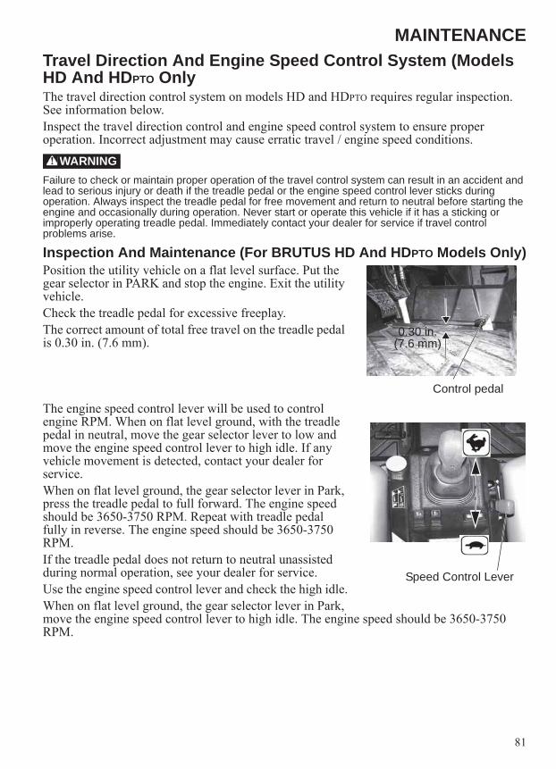
81
MAINTENANCETravel Direction And Engine Speed Control System (Models HD And HDPTO OnlyThe travel direction control system on models HD and HDPTO requires regular inspection. See information below.Inspect the travel direction control and engine speed control system to ensure proper operation. Incorrect adjustment may cause erratic travel / engine speed conditions.
Failure to check or maintain proper operation of the travel control system can result in an accident and lead to serious injury or death if the treadle pedal or the engine speed control lever sticks during operation. Always inspect the treadle pedal for free movement and return to neutral before starting the engine and occasionally during operation. Never start or operate this vehicle if it has a sticking or improperly operating treadle pedal. Immediately contact your dealer for service if travel control problems arise.
Inspection And Maintenance (For BRUTUS HD And HDPTO Models Only)Position the utility vehicle on a flat level surface. Put the gear selector in PARK and stop the engine. Exit the utility vehicle.Check the treadle pedal for excessive freeplay.The correct amount of total free travel on the treadle pedal is 0.30 in. (7.6 mm).
The engine speed control lever will be used to control engine RPM. When on flat level ground, with the treadle pedal in neutral, move the gear selector lever to low and move the engine speed control lever to high idle. If any vehicle movement is detected, contact your dealer for service.When on flat level ground, the gear selector lever in Park, press the treadle pedal to full forward. The engine speed should be 3650-3750 RPM. Repeat with treadle pedal fully in reverse. The engine speed should be 3650-3750 RPM.If the treadle pedal does not return to neutral unassisted during normal operation, see your dealer for service.Use the engine speed control lever and check the high idle.When on flat level ground, the gear selector lever in Park, move the engine speed control lever to high idle. The engine speed should be 3650-3750 RPM.
WARNING
0.30 in. (7.6 mm)
Control pedal
Speed Control Lever

82
MAINTENANCEEngine OilAlways check the oil level daily. Change the engine oil at the intervals outlined in the Periodic Maintenance Chart beginning on page 73. Always change the oil filter whenever changing oil. WARNING! Vehicle operation with insufficient, deteriorated or contaminated engine oil will cause accelerated wear and may result in engine seizure, accident and injury. Always perform the maintenance procedures as outlined in the Periodic Maintenance Chart.
Oil RecommendationsNOTICE: Use of a non-recommended engine oil may cause serious engine damage.POLARIS recommends the use of POLARIS Diesel Oil (SAE CI-4) for this vehicle. Always use the correct viscosity grade based on the ambient temperature expected during operation. See the chart below.Oil Viscosity/Ambient Air Temperature Chart
Oil CheckThe oil dipstick is located on the engine under the passenger seat.Tip: Engine oil should be checked cold or allow time for the
oil to drain back into pan before checking to prevent overfilling.
1. Position the vehicle on a level surface.2. Stop the engine.3. Tilt the rear cargo box to access the engine oil
dipstick.4. Remove the dipstick. Wipe it dry with a clean
cloth.5. Reinstall the dipstick, then remove it and check the
oil level. Maintain the oil level in the safe range. Do not overfill.
Tip: Due to the dipstick entry angle into the crankcase, the oil level will read higher on the bottom side of the dipstick. Always read the level on the upper surface of the dipstick.
-25° F(-31° C)
+5° F(-15° C)
+80° F(+27° C)
+104° F(+40° C)
SAE 15W-40
Synthetic 5W-40
SAE 10W-30
Safe
{Safe Range
Check Level on Top Side
Dipstick
Add

83
MAINTENANCEEngine OilOil and Filter ChangeAlways change the oil and filter at the intervals outlined in the Periodic Maintenance Chart beginning on page 73. Always change the oil filter whenever changing oil.1. Position the vehicle on a level surface.2. Run the engine for two to three minutes until warm. Stop the engine.3. Clean the area around the drain plug. 4. Place a drain pan beneath the engine crankcase.CAUTION! Hot oil can cause burns to skin. Do not allow hot oil to contact skin.5. Remove the drain plug. Allow the oil to drain completely.6. Reinstall the sealing washer on the drain plug. The sealing surfaces on drain plug and
crankcase should be clean and free of burrs, nicks or scratches.7. Reinstall the drain plug. Torque to 25 ft-lbs (34 Nm).8. Place shop towels beneath the oil filter. Using an oil filter wrench, turn the filter counter-
clockwise to remove it.9. Using a clean dry cloth, clean the filter sealing surface on the crankcase.10. Lubricate the o-ring on the new filter with a film of fresh engine oil. Check to make sure
the o-ring is in good condition.11. Install the new filter and turn by hand until the filter gasket contacts the sealing surface,
then turn and additional 1/2 turn.12. Remove the oil fill cap and add 2.75 quarts (2.6 l) of the recommended oil.13. Reinstall the oil fill cap.14. Shift the transmission to PARK. 15. Apply the brakes.16. Start the engine. Allow it to idle for one to two
minutes. 17. Stop the engine. Inspect for leaks.18. Allow time for the oil to drain back into the pan
before checking to prevent overfilling the engine. Check the oil level on the dipstick and add oil as necessary to bring the level to the upper mark on the dipstick.
19. Dispose of used filter and oil properly.
Oil Fill Cap

84
MAINTENANCEGearcasesGearcase Specification Chart
Transmission (Main Gearcase)Always check and change the transmission oil at the intervals outlined in the Periodic Maintenance Chart beginning on page 73. Maintain the oil level even with the bottom of the fill plug hole threads.Refer to the Gearcase Specifications Chart for recommended lubricants, capacities and torque specifications. See page 119 for the part numbers of POLARIS products.Oil CheckThe fill plug is located on the right side of the transmission. Access the fill plug from the rear right-hand side of the vehicle. 1. Position the vehicle on a level surface. Remove the fill plug.2. Check the oil level. Add the recommended oil as needed.3. Reinstall the fill plug. Torque to specification.Oil ChangeThe drain plug is located on the bottom of the transmission. Access the drain plug from under the rear of the vehicle.1. Remove the fill plug.2. Place a drain pan under the vehicle at the location
of the drain plug.3. Remove the drain plug. Allow the oil to drain
completely.4. Clean and reinstall the drain plug. Torque to
specification.5. Add the recommended oil. 6. Reinstall the fill plug. Torque to specification.7. Check for leaks. Dispose of used oil properly.
Gearcase SpecificationsGearcase Lubricant Capacity Fill Plug Torque Drain Plug Torque
Main Gearcase(Transmission)
AGL Full Synthetic Gearcase Lubricant &
Transmission Fluid
41 oz.(1200 ml)
12 ft-lbs(16.3 Nm)
12 ft-lbs(16.3 Nm)
Front Gearcase Demand Drive Fluid 6.75 oz.(200 ml)
8-10 ft-lbs(11-13.6 Nm
8-10 ft-lbs(11-13.6 Nm)
Fill PlugFill Level
Drain Plug

85
MAINTENANCEGearcasesFront GearcaseAlways check and change the front gearcase oil at the intervals outlined in the Periodic Maintenance Chart beginning on page 73. Maintain the oil level even with the bottom thread of the fill plug hole. Refer to the Gearcase Specifications Chart on page 84 for recommended lubricants, capacities and torque specifications. See page 119 for the part numbers of POLARIS products.Oil CheckThe front gearcase fill plug is located on the right side of the front gearcase.1. Position the vehicle on a level surface.2. Remove the fill plug. Check the oil level. 3. Add the recommended oil as needed.4. Reinstall the fill plug. Torque to specification.Oil Change1. Support the vehicle securely on jack stands.2. Remove the fill plug.
3. Place a drain pan under the drain plug on the bottom of the gearcase.
4. Remove the drain plug. Allow the oil to drain completely.
5. Clean and reinstall the drain plug. Torque to specification.
6. Add the recommended oil.7. Reinstall the fill plug. Torque to specification. 8. Check for leaks. Dispose of used oil properly.
Fill Plug
Drain Plug
86
MAINTENANCECooling SystemThe engine coolant level is controlled or maintained by the recovery system. The recovery system components are the overflow bottle, radiator filler neck, radiator pressure cap and connecting hose.As coolant operating temperature increases, the expanding (heated) excess coolant is forced out of the radiator, past the pressure cap, and into the overflow bottle. As engine coolant temperature decreases, the contracting (cooled) coolant is drawn back up from the tank, past the pressure cap, and into the radiator.Some coolant level drop on new vehicles is normal as the system is purging itself of trapped air. Observe coolant levels and maintain as recommended by adding coolant to the overflow bottle.Adding or Changing CoolantTo ensure that the coolant maintains its ability to protect the engine, we recommend that the system be completely drained every two years and a fresh mixture of antifreeze and water added.NOTICE: Do not mix different types of coolant in the cooling system when adding coolant. Mixing
types can result in damage to the cooling system.POLARIS recommends the use of POLARIS Antifreeze 60/40 Premix or a 50/50 mixture of high quality aluminum compatible anti-freeze/coolant and distilled water. POLARIS antifreeze 60/40 is already premixed and ready to use. Do not dilute with water. Always follow the manufacturer's mixing recommendations for the freeze protection required in your area.Any time the cooling system has been drained for maintenance or repair, replace the coolant. If the recovery bottle has run dry, the level in the radiator should be inspected. Add coolant as needed.Radiator and Cooling FanAlways check and clean the screen and radiator fins at the intervals outlined in the Periodic Maintenance Chart beginning on page 73. Do not obstruct or deflect air flow through the radiator by installing unauthorized accessories in front of the radiator or behind the cooling fan. Interference with the radiator air flow can lead to overheating and consequent engine damage.NOTICE: Washing the vehicle with a high-pressure hose could damage the radiator fins and impair
the radiator's effectiveness. Using a high-pressure system is not recommended.

87
MAINTENANCECooling SystemOverflow Bottle Coolant LevelAlways check and change the coolant at the intervals outlined in the Periodic Maintenance Chart beginning on page 73. Maintain the coolant level between the minimum and maximum marks on the bottle (when the fluid is cool). The overflow bottle is located under the hood. 1. Position the vehicle on a level surface.2. View the coolant level in the overflow bottle.3. If the coolant level is below the safe operating
range, lift the hood and locate the overflow bottle lid. Remove the cap and the rubber vented plug and use a funnel to add coolant through the filler opening. Reinstall the rubber vented plug and the cap.
Tip: If coolant must be added often, or if the overflow bottle runs completely dry, there may be a leak in the system. Have the cooling system inspected by your POLARIS dealer.
Radiator Coolant Level1. Lift the hood.CAUTION! Escaping steam can cause burns. Never remove the pressure cap while the engine is warm or hot. Always allow the engine to cool before removing the pressure cap.2. Slowly remove the radiator cap.3. View the coolant level through the opening.4. Use a funnel and slowly add coolant as needed.Tip: This procedure is required only if the cooling system has
been drained for maintenance and/or repair. But if the overflow bottle has run dry, the level in the radiator should also be inspected.
5. Reinstall the pressure cap. Use of a non-standard pressure cap will not allow the recovery system to function properly. See your dealer for the correct replacement part.
Maximum Minimum
Pressure Cap

88
MAINTENANCEVehicle ImmersionNOTICE: If your vehicle becomes immersed, major engine damage can result if the machine is not
thoroughly inspected. Take the vehicle to your dealer before starting the engine.If it's impossible to take your BRUTUS to a dealer before starting it, follow the steps outlined below.1. Move the vehicle to dry land or at the very least, to water below the floorboards.2. Drain water from the intake drain valve and thoroughly dry the pre-filter box (located at
the left OPS post). See page 90.3. Dry any water that is present in the air cleaner housing. Filter replacement is required if
water is present.4. Remove the air intake resonator box and drain any water that is present. Dry the box
thoroughly.NOTICE: If you believe water has entered the engine, Do Not start the engine. Engine damage will
result. Take the vehicle to your dealer before starting the engine.5. Take the vehicle to your dealer for service as soon as possible, whether you succeed in
starting it or not.6. Check the hydraulic fluid and differential fluid. If any indication of moisture is present,
replace the fluid and filters.

89
MAINTENANCEFuel Filter/Water SeparatorThe fuel filter/water separator is located under the cargo box on the left side of the vehicle.Inspect the separator daily for leaks. Drain water and replace the separator at the intervals outlined in the Periodic Maintenance Chart beginning on page 73. Service the separator more frequently if the vehicle is operated with poor quality fuel.CAUTION! Both fuel and water will drain from the separator during the following procedure. Use caution and observe all fuel safety precautions when handling fuel.1. Raise the cargo box.2. Place an appropriate container under the fuel filter
drain to catch fluids (water and fuel).3. Slightly loosen the bleed screw to relieve fuel pressure in the filter. Do not tighten the
screw at this time.4. Reach under the fuel filter and slightly loosen the drain valve until the fluids drain from
the drain hole. Do not completely unscrew the drain valve.5. When fluids stop draining from the valve, tighten
the valve firmly (by hand only). 6. Tighten the bleed screw.7. With the gear selector in Park, turn the key to the
ON position. Do Not start the engine.8. The fuel pump will start pumping fuel with the key
in the ON position (10 -15 seconds) and will force air out of the fuel system.
9. At times it may be necessary to open the bleed screw on the fuel filter housing until fuel comes from the valve with no air bubbles.
10. Clean up any spilled fuel and soiled shop towels properly.
11. Start the engine and check for fuel leaks.12. Lower the cargo box.
Drain Valve Bleed Screw
Drain Hole(viewed from bottom)
Tighten
Loosen

90
MAINTENANCEAir Pre-FilterAlways clean the pre-filter at the intervals outlined in the Periodic Maintenance Chart beginning on page 73. Service the pre-filter more frequently if the vehicle is operated in wet or dusty conditions or at high engine RPM for extended periods.The intake air pre-filter is located in the access panel on the left rear OPS post. The pre-filter traps larger particles before the air reaches the main engine air filter.Removal1. Press the latch towards the front of the vehicle to
remove the pre-filter.2. Clean debris from the pre-filter and inspect for
damage. If any damage is found, replace the pre-filter assembly.
3. DO NOT use compressed air to clean the pre-filter open. Use a damp cloth and clean the inside of the pre-filter opening.
Installation1. Insert the two tabs on the pre-filter assembly into
the side frame. 2. Rotate the pre-filter into the frame and make sure
the latch securely retains the pre-filter to it’s original location.
Pre-Filter
Pre-Filter
Latch
Pre-Filter Housing

91
MAINTENANCEAir FilterAlways change the air filter at the intervals outlined in the Periodic Maintenance Chart beginning on page 73. Service the air filter more frequently if the vehicle is operated in wet or dusty conditions or at high engine RPM for extended periods. Lift the cargo box to access the air box.1. Release the two air box cover clips. Remove the air
box cover.
2. Remove the air filter assembly with a pulling and twisting motion. Use care to avoid damaging the filter element.
NOTICE: Operating a diesel engine with a soiled or damaged air filter can result in engine damage. Do not attempt to wash the filter. Always replace a soiled or damaged filter with a new filter.
3. Clean any dirt or deposits from the air box.4. Reinstall the filter into the air box. Make sure it fits
tightly.5. Install the cover and secure the with the two clips.
Clip ClipCover
Filter
Clean Air Box

92
MAINTENANCECleaning Intake Water Drain Valve1. Raise the cargo box.2. An air intake water drain valve is located below the
pre-filter that should be inspected and clean at the same time the pre-filter is cleaned.
3. Remove dirt and debris from the valve and squeeze the valve to make sure it is not plugged. If any damage is found, replace the drain valve.
Hydraulic/Hydrostatic SystemChecking FluidWARNING! Always clean up spilled fuel or oil. Keep heat, flames, sparks or lighted tobacco away from fuel and oil. Failure to use care around combustibles can cause explosion or fire.1. Use only recommended fluid in the hydraulic system.2. Park the utility vehicle on a flat level surface,
lower the attachment arm and put the attachment flat on the ground. See page 42.
3. Move the gear selector lever to Park, stop the engine and exit the utility vehicle. See page 40.
4. Raise the cargo box. See page 57.5. Check the fluid level in the sight gauge. The fluid
level is correct when at the center of the sight gauge.
6. Use only recommended POLARIS hydraulic fluid when adding or changing the hydraulic fluid. See page 119.
Adding Fluid1. Clean the area around the fill cap.2. If needed, remove the fill/breather cap and add fluid.3. Lower the cargo box. See page 57.
Water Drain Valve
Sight Gauge Fill Cap

93
MAINTENANCEHydraulic/Hydrostatic SystemRemoving And Replacing Hydraulic/Hydrostatic FilterChange the hydraulic/hydrostatic filter at the intervals outlined in the Periodic Maintenance Chart beginning on page 73.1. Park the utility vehicle on a flat level surface, lower the attachment arm and put the
attachment flat on the ground.2. Move the gear selector lever to Park, stop the
engine and exit the utility vehicle. See page 40.3. Raise the cargo box. See page 57.4. Replace the fluid if it becomes contaminated or
after major repair.5. Thoroughly clean the area around the fill cap.6. Loosen the fill / breather cap to relieve hydraulic
system pressure.WARNING! Diesel fuel or hydraulic fluid under pressure can penetrate skin or eyes, causing serious injury or death. Fluid leaks under pressure may not be visible. Use a piece of cardboard or wood to find leaks. Do not use your bare hand. Wear safety goggles. If fluid enters skin or eyes, get immediate medical attention from a physician familiar with this injury.7. Place a container under the filter. Recycle or
dispose of used oil in an environmentally safe manner.
8. Remove the hydraulic filter.9. Clean the surface of the filter housing where the
filter contacts the housing.10. Put clean oil on the seal of the new filter. Install
and hand tighten.11. Tighten the fill / breather cap.12. Recycle or dispose of used fluid in an
environmentally safe manner.WARNING! Always clean up spilled fuel or oil. Keep heat, flames, sparks or lighted tobacco away from fuel and oil. Failure to use care around combustibles can cause explosion or fire.13. Lower the cargo box. See page 57.14. Start the engine and operate the hydraulic controls. Stop the engine and check for leaks.15. Check fluid level and add as needed. See page 92.16. Use only recommended fluid in the hydraulic system. See page 119.
Fill/Breather Cap
Hydraulic/Hydrostatic Filter

94
MAINTENANCEHydraulic/Hydrostatic SystemRemoving And Replacing Hydraulic/Hydrostatic FluidChange the hydraulic/hydrostatic fluid at the intervals outlined in the Periodic Maintenance Chart beginning on page 73.Replace the fluid if it becomes contaminated or after major repair. Always replace the hydraulic / hydrostatic filters whenever the hydraulic fluid is replaced.1. Move the gear selector lever to Park and stop the
engine. See page 40.
2. Raise the cargo box. See page 57. 3. Remove the clamp and the hose from the gear
pump fitting and drain the hydraulic fluid into a container.
4. Thoroughly clean the area around the fill cap.5. Slowly loosen the fill / breather cap to relieve
hydraulic system pressure in the tank. Remove the fill / breather cap.
6. Remove and clean the hydraulic fill screen. Use low air pressure to clean the screen.
7. Remove the hydraulic filter. see page 93. Install a new filter.
8. Dispose of the used fluid in an environmentally safe manner.
9. Install the fill screen and fill to the proper level. See Page 94.
10. Install and tighten the fill / breather cap.11. Lower the cargo box. See page 57.WARNING! Always clean up spilled fuel or oil. Keep heat, flames, sparks or lighted tobacco away from fuel and oil. Failure to use care around, combustibles can cause explosion or fire.12. Start the engine and operate the hydraulic controls. If any hydraulic function operation is
not smooth, this may indicate that air is trapped in the hydraulic system. Continue to operate all the hydraulic functions until operation is smooth.
13. Stop the engine and check for leaks.14. Check fluid level and add as needed.
HoseClamp
Fill Cap
Fill Screen

95
MAINTENANCESpark Arrester
Failure to heed the following warnings while servicing the spark arrester could result in serious injury or death.Do not perform service on the spark arrester while the system is hot. Exhaust system temperatures can reach 1000° F. Allow components to cool sufficiently before proceeding.Remove any combustible materials from the area.Wear eye protection and gloves.Do not stand behind or in front of the vehicle while purging.Never run the engine in an enclosed area. Exhaust can cause loss of consciousness or death in a very short time. Never go under the vehicle while it's inclined.
Use the following procedure to periodically purge accumulated carbon from the exhaust pipe.1. Remove the arrester clean-out plug located on
the bottom of the muffler.2. Place the transmission in Park. Start the
engine.3. Press the brake pedal and then press the treadle
pedal to increase engine RPM. Purge accumulated carbon from the system by momentarily revving the engine several times.
4. If carbon is expelled, partially cover the exhaust outlet and rap on the pipe around the clean-out plug while revving the engine several more times.
5. If particles are still suspected to be in the muffler, elevate the rear of the vehicle one foot higher than the front. Block the wheels.
6. Repeat steps 3 and 4 until no more particles are expelled when the engine is revved. 7. Stop the engine. Allow the arrester to cool.8. Reinstall the arrester plug and remove the partial outlet cover.
WARNING
Clean-Out PlugExhaust Outlet

96
MAINTENANCEBrakesThe front and rear brakes are hydraulic disc type brakes activated by the brake pedal. See page 24.Brake FluidInspect the brake system routinely. Inspect the level of the brake fluid before each operation.WARNING! After opening a bottle of brake fluid, always discard any unused portion. Never store or use a partial bottle. Brake fluid is hygroscopic, meaning it rapidly absorbs moisture from the air. The moisture causes the boiling temperature of the brake fluid to drop, which can lead to early brake fade and the possibility of accident or severe injury.Change the brake fluid every two years and any time the fluid becomes contaminated, the fluid level is below the minimum, or if the type and brand of the fluid in the reservoir are unknown.1. Position the vehicle on a level surface. 2. View the brake fluid level at the reservoir in the
driver’s side wheel well.3. The level should be between the upper (MAX) and
lower (MIN) level lines.4. If the fluid level is lower than the upper level line,
add brake fluid to the upper (MAX) line. 5. Apply the brake forcefully for a few seconds and
check for fluid leakage around the fittings.
Brake Inspection1. Check the brake system for fluid leaks.2. Check the brake pedal for excessive travel or a
spongy feel. 3. Check the friction pads for wear, damage and
looseness.4. Check brake discs for signs of cracks, excessive
corrosion, warping or other damage. Clean any grease using an approved brake cleaner or alcohol.
NOTICE: Do not apply WD-40 or any petroleum product to brake discs.
5. Inspect the brake disc spline and pad wear surface for excessive wear. Change pads when worn to 3/64” (1 mm).
Maximum
Minimum
3/64" (1mm)

97
MAINTENANCEShift Cable AdjustmentInspectionShift cable adjustment is necessary when any of the following is noticed:• Noise on deceleration.• Inability to engage a gear.• Excessive gear clash (noise).• Gear selector is moving out of desired range.Inspect the shift cable, clevis pins, and pivot bushings and replace if worn or damaged. Check the cable adjustment per the following procedure.WARNING! Stop engine and chock both rear tires before inspecting or adjusting the shift cable.1. Stop the vehicle on flat level surface, put the gear
selector in PARK and stop the engine.2. Chock the wheels.3. With the gear selector lever in the Park position. Make sure the lever is not contacting
the bottom of the shift slot.4. Move the gear selector lever to the High position. Make sure the lever is not contacting
the top of the shift slot.If there is any contact at either the bottom or the top of the gear selector shift slot, the shift cable will need to be adjusted. Do the following adjustment:1. Loosen the jam nuts.2. Rotate the two jam nuts, as needed, to move the
gear selector lever up or down so the lever does not contact the slot at either the bottom or top position.
3. Evenly tighten the two jam nuts until tight to the cable mount.
4. Check operation of the gear selector. (Have the vehicle in an open area with no bystanders or place the vehicle on jack stands.) Start the engine. With the gear selector in Park (the P light will be illuminated), slowly increase the treadle pedal in the forward direction. No utility vehicle movement should occur and no gear clash noise detected. Shift into High gear (the H light will be illuminated), slowly increase the treadle pedal in the forward direction to check forward travel. Shift into Low gear (the L light will be illuminated), slowly increase the treadle pedal in the forward direction to check forward travel. Move the gear selector to neutral (the N light will be illuminated), slowly increase the treadle pedal in the forward direction. No utility vehicle movement should occur and no gear clash noise detected.
If the gear selector lever and cable can not be adjusted as indicated above, see your dealer for service.
LeverTop Shift Slot
Bottom Shift Slot
Jam Nuts

98
MAINTENANCESteering Wheel InspectionCheck the steering wheel for specified freeplay and smooth operation at the intervals outlined in the Periodic Maintenance Chart beginning on page 73. 1. Position the vehicle on level ground.2. Lightly turn the steering wheel left and right.3. There should be 0.8”-1.0” (20-25 mm) of freeplay.4. If there is excessive freeplay or strange noises, or the steering feels rough or “catchy,”
have the steering system inspected by an authorized POLARIS dealer.
Suspension / Spring AdjustmentsNOTICE: For BRUTUS HD and HDPTO models, the front shock absorber spring setting should NOT
be changed. For these models, the factory has pre-set the spring rate for optimal performance for use with the various attachments that can be installed on the attachment arm.
BRUTUS model: Adjust the rear and front shock absorber springs by rotating the adjustment cam either clockwise or counter-clockwise to increase or decrease spring tension.BRUTUS HD and HDPTO models: Adjust the rear shock absorber springs by rotating the adjustment cam either clockwise or counter-clockwise to increase or decrease spring tension.
Place the vehicle on jack stands. See page 107. Adjust the front (BRUTUS only) and rear shock absorber springs by rotating the adjustment cam either clockwise or counter-clockwise to increase or decrease spring tension.Tip: No tool is included for suspension adjustment, see your dealer for adjustment.
Cam
Rear Suspension ShownAdjustment is similar for Front Suspension

99
MAINTENANCEAlternator BeltBelt AdjustmentCheck the alternator belt at the correct service interval as outlined in the Periodic Maintenance Chart beginning on page 73. Stop the machine on a flat level surface. Put the gear selector in Park, stop the engine and exit the vehicle. See page 40.1. Raise the cargo box. See page 57.2. Remove the three bolts and remove the shield.
3. The belt tension is correct with 5/16-1/2 in. (7-10 mm) of belt deflection at the mid span of the belt, when 20 lbf (89 N) is applied to the belt.
4. If the belt tension is not correct, loosen the mounting bolt and adjustment bolt.
5. Move the top of the alternator to tighten the belt.6. Tighten the mounting bolt to 15 ft-lbs (20 Nm).7. Tighten the adjustment bolt to 28 ft-lbs (38 Nm).8. Install the shield and three bolts.9. Lower the cargo box. See page 57.
Shield Bolt
BoltMid Span
Adjustment Bolt Alternator
Mounting Bolt
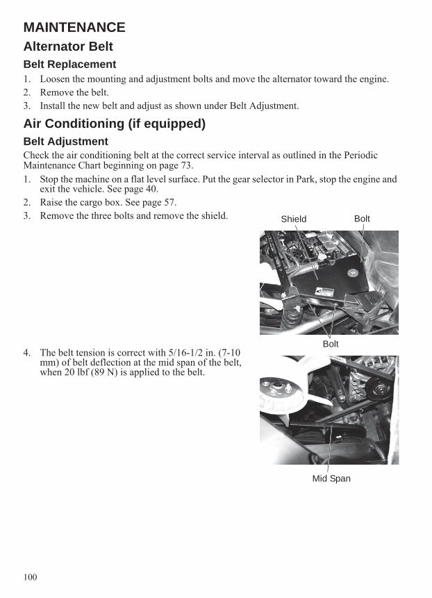
100
MAINTENANCEAlternator BeltBelt Replacement1. Loosen the mounting and adjustment bolts and move the alternator toward the engine.2. Remove the belt.3. Install the new belt and adjust as shown under Belt Adjustment.
Air Conditioning (if equipped)Belt AdjustmentCheck the air conditioning belt at the correct service interval as outlined in the Periodic Maintenance Chart beginning on page 73. 1. Stop the machine on a flat level surface. Put the gear selector in Park, stop the engine and
exit the vehicle. See page 40.2. Raise the cargo box. See page 57.3. Remove the three bolts and remove the shield.
4. The belt tension is correct with 5/16-1/2 in. (7-10 mm) of belt deflection at the mid span of the belt, when 20 lbf (89 N) is applied to the belt.
Shield Bolt
Bolt
Mid Span

101
MAINTENANCEAir Conditioning (if equipped)Belt Adjustment5. If the belt tension is not correct, loosen the
mounting bolt and adjustment bolt.6. Move the top of the compressor to tighten the belt.7. Tighten the mounting bolt to 15 ft-lbs (20 Nm).8. Tighten the adjustment bolt to 28 ft-lbs (38 Nm).9. Install the shield and three bolts.10. Lower the cargo box. See page 57.
Belt Replacement1. Loosen the mounting and adjustment bolts and
move the compressor toward the engine. 2. Remove the belt.3. Install the new belt and adjust as shown under Belt Adjustment.Filter CleaningThe air conditioning filter is located below the dash.1. Remove the two fasteners and remove the filter
cover.2. Clean the filter with low air pressure. Check for
damage, replace if damaged.
Adjustment Bolt
Mounting Bolt
Fasteners
Filter Cover
Filter

102
MAINTENANCEAir Conditioning (if equipped)Condenser CleaningIf equipped with air conditioning, the condenser should be cleaned at the correct service interval as outlined in the Periodic Maintenance Chart beginning on page 73. 1. Stop the machine on a flat level surface. Put the gear selector in Park, stop the engine and
exit the vehicle. See page 40.2. Turn the two fasteners counter-clockwise 1/4 turn
and open or remove the cover.
3. Use low pressure air or water to clean the condenser.
4. Close the door and turn the two 1/4 turn fasteners clockwise.
Cover Fasteners
Condenser

103
MAINTENANCEPTO Clutch (If Applicable)The PTO system is activated by engaging an electric clutch. When the clutch is engaged, the PTO driveline will rotate. When disengaged, a PTO brake is applied.The PTO clutch brake must be checked and adjusted periodically as outlined in the Periodic Maintenance Chart beginning on page 73. Adjusting The PTO Clutch Brake1. Put the gear selector in Park, stop the engine and
exit the vehicle. See page 40. 2. Remove the passenger seat and the storage
container to access the PTO clutch. See page 25.3. Use a feeler gauge, and insert the end of the feeler
gauge into the edge of the clutch pack to a depth of 0.31 in. (8 mm) and measure the clearance.
4. Measure in three places (in the three openings in between the three adjusting nuts) to determine the clearance in all three areas on the clutch pack. The clearance must be 0.014 in. (0.35 mm) in all the three areas.
Tip: Do not insert the end of the feeler gauge more than 0.31 in. (8 mm) into the side of the clutch to get an accurate measurement.
5. Tighten or loosen the three adjusting nuts until the correct clearance is achieved evenly (at the three areas checked) on the clutch.
6. The PTO clutch is removed.
Adjustable NutsFeeler Gauge
0.31 in.(8 mm)
Feeler Gauge

104
MAINTENANCEPTO Drive Belt (If Applicable)Belt InspectionCheck the PTO drive belt at the correct service interval as outlined in the Periodic Maintenance Chart beginning on page 73.The PTO drive belt has a constant tension idler to keep the correct tension on the belt.1. Stop the machine on a flat level surface. Put the gear selector in Park, stop the engine and
exit the vehicle. See page 40.2. Raise the cargo box. See page 57.3. The drive belt idler is under constant spring load to keep the belt at the correct tension.
No adjustment can be made. 4. If belt slippage is noticed, the belt and / or the constant tension pulley must be replaced. 5. Inspect belt condition. If belt wear, including the side
of the belt is visible, belt replacement is needed. See your dealer for service).
Tip: If the PTO belt needs replacement, the bell housing and hydrostatic pump removal is required. See your dealer for service.
PTO Gearbox (If Applicable)Checking PTO Gearbox FluidTip: Periodic inspection of the gearbox fluid is not needed.
Visually inspect the gearbox for fluid leaks. If any leak is suspected, then check fluid level.
Check the PTO gearbox fluid as outlined in the Periodic Maintenance Chart beginning on page 73. The PTO gearbox requires special synthetic fluid. Use only recommended fluid in the PTO gearcase.1. Stop the machine on a flat level surface. Put the
gear selector in Park, stop the engine and exit the vehicle. See page 40.
2. To check the fluid level, the breather tube fitting must be removed and the fluid level check through the fitting opening. This port must be used for checking the fluid level as the other plug in the top cover is positioned over a gear so there is no access to the bottom of the gearcase.
Drive Belt Idler
Breather Tube Fitting
Tubing
Cut Tubing
2.17 in.(55 mm)
CorrectOil Level
T40 Tool or equivalent
0.43 in.(11 mm)
T 40Wrench

105
MAINTENANCEPTO Gearbox (If Applicable)Checking PTO Gearbox Fluid3. To check the fluid level, use the T40 wrench that is included in the tool kit (or an
equivalent tool) and a piece of tubing that fits snuggly over the tool. 4. Mark the tool at two places, at 0.43 inches (11 mm) and at 2.17 inches (55 mm). 5. Slide a piece of tubing over the tool to use as a stop and set it at the 2.17 inches (55 mm)
mark. 6. The correct oil level is between the tip of the tool
and the 0.43 inches (11 mm) mark. If the oil level is low, add fluid. Do not overfill.
7. If the fluid level is above the mark, it may indicate that moisture has been ingested into the oil and has contaminated the oil.
8. If moisture is present, replace the fluid. Also, if moisture is present, check the breather tube to make sure it is in the correct location.
9. If the breather tube has been allowed to hang down, water can enter the breather tube and be sucked into the gearcase.
10. Install the fitting and place the end of the breather tube in the cross member that is behind the operator’s seat.
Adding PTO Gearbox FluidThe PTO gearbox should not require adding fluid. If the fluid level drops, it would indicate a leak. See your dealer for repairs.
Breather Tube

106
MAINTENANCEPTO Gearbox (If Applicable)Removing And Replacing PTO Gearbox FluidReplace the PTO gear fluid at the correct service interval as outlined in the Periodic Maintenance Chart beginning on page 73.1. Stop the machine on a flat level surface. Put the gear selector in Park, stop the engine and
exit the vehicle. See page 40.2. Install a container under the drain plug.3. Remove the drain plug. Dispose of the used fluid
in an environmentally safe manner.4. Reinstall the drain plug.
Torque: 11 ft-lbs (15 Nm)5. The PTO gearbox requires special synthetic fluid.
Use only recommended fluid in the PTO gearcase.
6. Thoroughly clean the area around the breather tube fitting and remove the fitting.
7. Install a piece of clear tubing on the end of the gearcase fluid bottle. Add the proper amount of fluid to the gearcase.
8. Reinstall the fitting and make sure the end of the breather tube is positioned in the cross member that is behind the operators seat.
WARNING! Always clean up spilled fuel or oil. Keep heat, flames, sparks or lighted tobacco away from fuel and oil. Failure to use care around combustibles can cause explosion or fire.
Drain Plug
FittingBreather Tube
Clear TubeGearcase
Fluid Bottle

107
MAINTENANCESupporting Utility Vehicle On Jack StandsFor service work under the utility vehicle, or to remove the wheels, always support the utility vehicle with jack stands or blocks of adequate capacity for weight of utility vehicle. See specifications page 120.Always park the utility vehicle on a flat level surface. Put gear selector in Park, stop the engine and exit the vehicle.If removing wheel(s), loosen the wheel nuts slightly before lifting the vehicle.WARNING! Instructions are necessary before operating or servicing machine. Read and understand the Operator’s Manual, Operator’s Handbook (if equipped) and signs (decals) on machine. Follow warnings and instructions in the manuals when performing repairs, adjustments or service. Check for correct function after adjustments, repairs or service. Untrained operators and failure to follow instructions can cause injury or death.Place the jack stands under the front and rear frames of the utility vehicle (both sides).Tip: When lifting the utility vehicle, place jack under front and
rear frame.
Jack Stands

108
MAINTENANCETires
Operating your vehicle with worn tires, improperly inflated tires, non-standard tires or improperly installed tires will affect vehicle handling and could cause an accident resulting in serious injury or death. Always follow all tire maintenance procedures as outlined in this manual and on the labels on the vehicle. Always use original equipment size and type when replacing tires.
Tire Tread DepthAlways replace tires when tread depth is worn to 1/8” (3 mm) or less.Axle and Wheel Nut Torque SpecificationsInspect the following items occasionally for tightness, and if they've been loosened for maintenance service.Do not lubricate the stud or the lug nut.
Wheel Removal1. Apply the brakes. Move the gear selector lever to PARK. 2. Stop the engine.3. Loosen the wheel nuts slightly.4. Elevate the side of the vehicle by placing a suitable stand under the frame.5. Remove the wheel nuts and washers. Remove the
wheel.Wheel Installation1. Apply the brakes. 2. Move the gear selector lever to PARK.3. Place the wheel in the correct position on the wheel
hub. Be sure the valve stem is toward the outside and rotation arrows on the tire point toward forward rotation.
WARNING! Improperly installed wheels can adversely affect tire wear and vehicle handling, which can result in serious injury or death. Always ensure that all nuts are torqued to specification. Do not service axle nuts that have a cotter pin installed. See your POLARIS dealer.4. Attach the wheel nuts and washers and finger tighten.5. Carefully lower the vehicle to the ground.6. Torque the wheel nuts to specification.
Fastener Location Nut TorqueWheel Nut Front and Rear 60 ft-lbs (81 Nm)Spindle Nut Front 75 ft-lbs (102 Nm)Hub Retaining Nuts Rear 110 ft-lbs (150 Nm)
WARNING
1/8” (3 mm)

109
MAINTENANCELightsPoor lighting can result in reduced visibility when driving. Headlight and taillight lenses become dirty during normal operation. Clean lights frequently and replace burned out lamps promptly. Always make sure lights are adjusted properly for best visibility.When servicing a halogen lamp, don't touch the lamp with bare fingers. Oil from your skin leaves a residue, causing a hot spot that will shorten the life of the lamp.Brake LightsWhen the brake pedal is depressed, the brake light comes on. Check the brake light before each ride. 1. Turn the ignition switch to the ON position.2. Depress the brake pedal. The brake light should come on after about 0.4 in. (10 mm) of
pedal travel. If the light doesn't come on, check the rear light assembly.Headlight Lamp Replacement1. Open the hood.CAUTION! Hot components can cause burns to skin. Allow lamps to cool before servicing.2. Unplug the headlamp from the wiring harness. Be sure to pull on the connector, not on
the wiring.3. Turn the lamp counter-clockwise to remove it.4. Install the new lamp.Tip: Make sure the tab on the lamp locates properly in the housing.5. Reinstall the harness assembly into the headlight assembly.

110
MAINTENANCEFusesIf the engine stops or will not start, or if you experience other electrical failures, a fuse or relay may need replacement. Locate and correct any short circuits that may have caused a blown fuse, then replace the fuse. Spare fuses are provided in the fuse box. If you suspect that a fuse or relay may not be working properly, please see your POLARIS dealer.The fuse panel is located below the seat between the operator and passenger. For the BRUTUS model, remove the seat. For HD and HDPTO models, the center console will need to be removed.Additional relays and fuses are also located in the same area as the fuse and relay panels.
1. Relay = Radiator fan motor2. Relay = HVAC (if equipped)3. In-line fuse (30A) = HVAC (if equipped)4. Circuit Breaker (40A) = Radiator fan motor5. Circuit Breaker (20A) = Condenser fan
motor (if equipped)
12
4
3 5

111
MAINTENANCEBattery
Improperly connecting or disconnecting battery cables can result in an explosion and cause serious injury or death. When removing the battery, always disconnect the negative (black) cable first. When reinstalling the battery, always connect the negative (black) cable last.Your vehicle is equipped with a sealed battery, which requires little maintenance. Always keep battery terminals and connections free of corrosion. If cleaning is necessary, remove corrosion with a stiff wire brush. Wash with a solution of one tablespoon baking soda and one cup water. Rinse well with tap water and dry off with clean shop towels. Coat the terminals with dielectric grease or petroleum jelly.Battery Removal1. Remove the seat. The battery is located under the
passengers side of the vehicle.2. Disconnect the black (-) battery cable first.3. Disconnect the red (+) battery cable last.4. Remove the battery hold-down strap.5. Lift the battery out of the vehicle.Battery InstallationUsing a new battery that has not been fully charged can damage the battery and result in a shorter life. It can also hinder vehicle performance. Follow the battery charging instructions on page 112 before installing the battery.1. Ensure that the battery is fully charged.2. Place the battery in the battery holder. Install the battery hold-down strap.3. Coat the terminals with dielectric grease or petroleum jelly.4. Connect and tighten the red (+) cable first.5. Connect and tighten the black (-) cable last.
WARNING

112
MAINTENANCEBatteryBattery StorageWhenever the vehicle is not used for a period of three months or more, remove the battery from the vehicle, ensure that it's fully charged, and store it out of the sun in a cool, dry place. Check battery voltage each month during storage and recharge as needed to maintain a full charge. POLARIS recommends maintaining battery charge by using a POLARIS Battery Tender charger or by charging about once a month to make up for normal self-discharge. Battery Tender can be left connected during the storage period, and will automatically charge the battery if the voltage drops below a pre-determined point. See page 119 for the part numbers of POLARIS products.Battery ChargingThe following battery charging instructions apply only to the installation of a sealed battery. Read all instructions before proceeding with the installation of this battery. The sealed battery is already filled with electrolyte and has been sealed and fully charged at the factory. Never pry the sealing strip off or add any other fluid to this battery. Always keep a sealed battery fully charged. Since the battery is sealed and the sealing strip cannot be removed, you must use a voltmeter or multimeter to measure DC voltage.WARNING! An overheated battery may explode, causing severe injury or death. Always watch charging times carefully. Stop charging if the battery becomes very warm to the touch. Allow it to cool before resuming charging.For a refresh charge, follow all instructions carefully.1. Check the battery voltage with a voltmeter or multimeter. A fully charged battery will
register 12.8 V or higher.2. If the voltage is less than 12.8 volts, recharge the battery at 1.2 amps or less until battery
voltage is 12.8 or greater. 3. When using an automatic charger, refer to the charger manufacturer's instructions for
recharging. When using a constant current charger, use the guidelines below for recharging.
Always verify battery condition before and 1-2 hours after the end of charging.
State of Charge Voltage Action
Charge Time(Using constant current
charger @ standard ampsspecified on top of battery)
100% 12.8-13.0 volts None, check at 3 mos. from date of manufacture
None required
75%-100% 12.5-12.8 volts May need slight charge, if no charge given, check in 3 months
3-6 hours
50%-75% 12.0-12.5 volts Needs charge 5-11 hours25%-50% 11.5-12.0 volts Needs charge At least 13 hours, verify
state of charge0%-25% 11.5 volts or less Needs charge with desulfating
chargerAt least 20 hours

113
MAINTENANCEWheel Toe AlignmentInspectionThe wheel toe alignment requires regular inspection and maintenance at the correct service interval as outlined in the Periodic Maintenance Chart beginning on page 73.Stop the machine on a flat level surface. Put the gear selector in Park, stop the engine and exit the vehicle. See page 40.1. Turn the steering wheel so it is in the straight ahead position.2. Place a chalk mark on the center of the front tires at
approximately 10 in. (254 mm) up from the floor (or as close to the centerline of the front axle as possible.
Tip: It is important that the height of both marks be equally positioned to get an accurate measurement.
3. Measure the distance between the marks and record this measurement. (We will call this dimension A.)
4. Move the gear selector lever to Neutral and roll the vehicle ahead until the chalk marks are to the rear of the front tires (approximately at the centerline of the front axle). Move the gear selector lever to PARK.
5. Measure the distance between the chalk marks and record the dimension. (We will call this dimension B.)
6. The difference between dimension A and B is the toe alignment. The recommended toe tolerance is 0.125-0.25 inch (3.17-6.35 mm) toe out. (This means the measurement “A” in front of the tire should be wider than the measurement “B” at the rear of the tire.
Toe AdjustmentTip: Be sure the steering wheel is straight ahead before
determining which tie rod needs adjustment.If the toe alignment is incorrect, measure the distance between the center of the vehicle and each wheel. This will determine which tie rod needs adjusting.Tip: During tie rod adjustment, make sure to use a wrench on
both the tie rod end and the jam nut. Tie rod end damage could occur if the tie rod end is not held securely while loosening or tightening the tie rod jam nut.
1. Hold the tie rod end securely and loosen the jam nut.
2. Use a wrench on the flat spot on the tie rod and a wrench on the tie rod end. Rotate the tie rod to shorten or lengthen until the alignment is as required to achieve the proper toe setting.
3. When alignment is correct, hold the tie rod end securely and tighten the jam nut to 14-16 ft-lbs (16-19 Nm) torque.
10 in.254 mm
Chalk MarkPlace

114
MAINTENANCELubricating The Utility VehicleLubrication LocationLubricate as outlined in the Periodic Maintenance Chart beginning on page 73. Always use a good quality lithium based multi-purpose grease.Lubricate the following:
1. Lower A Arms (both sides)2. Upper A Arms (both sides)
3. Trailing Arm - Rear Pivot (both sides)
4. Trailing Arm - Front Pivot (both sides)
5. Upper Suspension Arm
2
1
3
4
5

115
MAINTENANCELubricating The Utility VehicleLubrication Location6. Drive Shaft (in front of transmission
7. Lift Cylinder Base End8. Lift Cylinder Rod End9. Tilt Cylinder Base End10. Tilt Cylinder Rod End
(bottom side of cylinder rod)11. Attachment Arm Pivot - Rear (both sides)12. Attachment Arm Pivot - Front (both sides)
6
7
89
10
11
12

116
MAINTENANCECleaning and StorageWashing the VehicleKeeping your POLARIS vehicle clean will not only improve its appearance but it can also extend the life of various components.NOTICE: High water pressure may damage components. POLARIS recommends washing the vehicle
by hand or with a garden hose, using mild soap. NOTICE: Certain products, including insect repellents and chemicals, will damage plastic surfaces.
Do not allow these types of products to contact the vehicle.The best and safest way to clean your POLARIS vehicle is with a garden hose and a pail of mild soap and water. 1. Use a professional-type washing cloth, cleaning the upper body first and the lower parts
last.2. Rinse with clean water frequently.3. Dry surfaces with a chamois to prevent water spots.Washing Tips• Avoid the use of harsh cleaners, which can scratch the finish.• Do not use a power washer to clean the vehicle.• Do not use medium to heavy duty compounds on the finish.• Always use clean cloths and pads for cleaning and polishing. Old or reused cloths and
pads may contain dirt particles that will scratch the finish.If a high pressure water system is used for cleaning (not recommended), exercise extreme caution. The water may damage components and could remove paint and labels. Avoid directing the water stream at the following items:
If an informational or graphic label becomes illegible or comes off, contact your POLARIS dealer to purchase a replacement. Replacement safety labels are provided by POLARIS at no charge.Lubricate all grease fittings immediately after washing. Allow the engine to run for a while to evaporate any water that may have entered the engine or exhaust system.
• Engine• Air Intake• Wheel bearings• Radiator
• Transmission seals• Brakes• Cab and body panels• Labels and decals
• Switches and controls• Electrical components and wiring

117
MAINTENANCECleaning and StoragePolishing the VehiclePOLARIS recommends the use of common household aerosol furniture polish for polishing the finish on your POLARIS vehicle. Follow the instructions on the container.Polishing Tips• Avoid the use of automotive products, some of which can scratch the finish of your
vehicle.• Always use clean cloths and pads for cleaning and polishing. Old or reused cloths and
pads may contain dirt particles that will scratch the finish.Storage TipsClean the ExteriorMake any necessary repairs and clean the vehicle as recommended. See page 116.Oil and FilterChange the oil and filter. See page 83.Air Filter / Pre-Filter1. Inspect and clean or replace the pre-filter and air filter. See page 90.2. Clean the air box, including sediment plugs.Inspect and LubricateInspect all cables and lubricate all areas of the vehicle as recommended in the Periodic Maintenance Chart beginning on page 73.Battery Maintenance See page 112 for storage and charging procedures.Fluid LevelsInspect the fluid levels. Add or change fluids as recommended in the Periodic Maintenance Chart beginning on page 73.• Front gearcase fluid• Transmission fluid• Hydraulic/Hydrostatic fluid• Brake fluid (change every two years and any time the fluid looks dark or contaminated)• Coolant (test strength/fill)Storage Area/CoversBe sure the storage area is well ventilated. Cover the vehicle with a genuine POLARIS cover. Do not use plastic or coated materials. They do not allow enough ventilation to prevent condensation, and may promote corrosion and oxidation.

118
MAINTENANCERemoval from Storage1. Charge the battery if necessary. Install it in the vehicle.2. Fill the fuel tank with fuel.3. Check all the points listed in the Daily Pre-Ride Inspection section on page 33.4. Lubricate at the intervals outlined in the Periodic Maintenance Chart beginning on page
73.
Transporting the BRUTUSFollow these procedures when transporting the vehicle.1. Apply the brakes. 2. Stop the engine.3. Place the transmission in PARK. 4. Secure the fuel cap, oil cap and seat.5. Always tie the frame of the BRUTUS to the transporting unit securely with suitable
straps or chains. Do not attach tie straps to the front A-arm bolt pockets. 6. Remove the key to prevent loss during transporting.

119
POLARIS PRODUCTSPart Number Description
Engine Lubricant2878473 15W-40 Diesel Oil, Summer (2 qts./1.9 l)2878474 10W-30 Diesel Oil, Winter (2 qts./1.9 l)2879832 5W-40 Synthetic Diesel Oil (2 qts./1.9 l)2878471 Diesel Oil Change Kit, Summer2878472 Diesel Oil Change Kit, Winter
Gearcase / Transmission Lubricants2878068 AGL Full Synthetic Gearcase Lubricant & Transmission Fluid (qt./.95 l)2878069 AGL Full Synthetic Gearcase Lubricant & Transmission Fluid (gal./3.8 l)2877922 Demand Drive Fluid (qt./.95 l)2877923 Demand Drive Fluid (gal./3.8 l)2870465 Pump for Gallon (3.8 l) Jug
Coolant2871323 POLARIS Antifreeze 60/40 Premix (gal./3.8 l)2871534 POLARIS Antifreeze 60/40 Premix (qt./.95 l)
Hydraulic Fluid2879746 POLARIS Hydraulic Fluid (gal./3.8 l)
PTO Gearbox Oil2879748 Synthetic PTO Gearbox Oil (6 oz./17.7 ml)
Grease / Specialized Lubricants2871312 Grease Gun Kit, All Season Grease2871322 All Season Grease (3 oz./89 ml cartridge)2871423 All Season Grease (14 oz./414 ml cartridge)2871460 Premium Starter Grease 2871515 U-Joint Grease (3 oz./89 ml cartridge)2871551 U-Joint Grease (14 oz./414 ml cartridge)2871329 Dielectric Grease (NyogelTM)
Miscellaneous2872189 DOT 4 Brake Fluid2859044 POLARIS Battery Charger
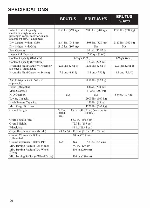
120
SPECIFICATIONS
BRUTUS BRUTUS HD BRUTUS HDPTO
Vehicle Rated Capacity(includes weight of operator, passenger, cargo, accessories, and attachment arm, if equipped)
1750 lbs. (794 kg) 2000 lbs. (907 kg) 1750 lbs. (794 kg)
Dry Weight (without Cab) 1634 lbs. (741 kg) 1808 lbs. (820 kg) 2120 lbs. (962 kg)Dry Weight (with Cab) 1915 lbs. (869 kg) NA NAFuel Capacity 10 gal. (37.85 l)Engine Oil Capacity 2.75 qts. (2.6 l)Coolant Capacity (Radiator) 6.2 qts. (5.9 l) 6.9 qts. (6.5 l)Coolant Capacity (Overflow) 7.5 oz. (222 ml)Hydraulic Fluid Capacity (Reservoir at center of sight gauge)
2.75 qts. (2.61 l) 2.75 qts. (2.61 l) 2.75 qts. (2.61 l)
Hydraulic Fluid Capacity (System) 7.2 qts. (6.81 l) 8.4 qts. (7.95 l) 8.4 qts. (7.95 l)
A/C Refrigerant - R134A (if applicable)
0.86 lbs. (1.9 kg)
Front Differential 6.8 oz. (200 ml)Main Gearcase 41 oz. (1200 ml)PTO Gearbox NA NA 6.0 oz. (177 ml)Towing Capacity 2000 lbs. (907 kg)Hitch Tongue Capacity 150 lbs. (68 kg)Max. Cargo Box Load 1250 lbs. (567 kg)Overall Length 122.2 in.
(310.4 cm)
158 in. (401.1 cm) (with bucket installed)
Overall Width (tires) 63.2 in. (160.6 cm)Overall Height 72.9 in. (185 cm)Wheelbase 84 in. (213.4 cm)Cargo Box Dimensions (Inside) 43.5 x 54 x 11.5 in. (110 x 137 x 29 cm)Ground Clearance - Below Differential
10 in. (25.4 cm)
Ground Clearance - Below PTO NA NA 7.2 in. (18.4 cm)Min. Turning Radius (Turf Mode) 90 in. (229 cm)Min. Turning Radius (Two Wheel Drive)
110 in. (280 cm)
Min. Turning Radius (4 Wheel Drive) 110 in. (280 cm)

121
SPECIFICATIONS
BRUTUS BRUTUS HD BRUTUS HDPTO
Engine YANMAR 3-Cylinder Inline DieselDisplacement 55.1 in.3 (904 cc)Bore x Stroke 2.83 in. x 2.91 in. (72mm x 74mm)Lubrication System Pressurized Wet SumpHigh Idle 3700 +/- 100 RPMLow Idle 1350 +/- 100 RPMAlternator Output 12V DC 90AStarting System ElectricFuel System Indirect InjectionFront Suspension Dual A-arm w/6 in. (15.2 cm) of travelRear Suspension DeDion w/6 in. (15.2 cm) of travelTreadle pedal Pedal Drive Hydrostatic Drive Forward/ReverseDriving System Type Hydrostatic driven, 4-wheel independent shaft, lockable differentialShift Type Single Lever (H/L/N/P)Gear Reduction - Low 4.41:1Gear Reduction - High 1.99:1Drive Ratio - Front: 3.82:1Drive Ratio - Rear 3.70:1Tire Size - Front 25 x 9 - 12Tire Size - Rear 25 x 11 - 12Tire Pressure - Front 10 psi (69 KPa) 20 psi (138 KPa) 20 psi (138 KPa)Tire Pressure - Rear 20 psi (138 KPa) 20 psi (138 KPa) 20 psi (138 KPa)Brakes, Front/Rear Foot Activated, 4 wheel hydraulic discHood Headlight 60/55W High/Low HalogenTaillights 10 L.E.D. (.28W)Brake Light 10 L.E.D. (3.1W)Indicator Light 1.0 WHydraulic Pump Engine driven gear typePump Capacity 7.6 gpm (28.8 l) @ 3600 RPMSteering Flow 2.2 gpm (8.3 l) @ 3600 RPMSteering Relief Valve 850 PSI (35.4 bar)Charge relief valve 87 PSI (6 bar)Filtration Full flow replaceable element with 50 PSI (3.4 bar) internal cold
weather by-pass valve

122
TROUBLESHOOTINGEngine Doesn't Turn Over
Engine Turns Over, Fails to Start
Engine Runs Irregularly, Stalls or Misfires
Engine Stops or Loses Power
Possible Cause SolutionLow battery voltage Recharge the battery to 12.8 VDCLoose battery connections Check all connections and tightenLoose solenoid connections Check all connections and tightenLoose electronic control box connections Inspect, clean, reinstall connectors
Possible Cause SolutionOut of fuel RefuelClogged fuel filter/water separator ReplaceClogged air filter ReplaceWater is present in fuel Drain the fuel system and refuel, replace fuel filter/
water separatorOld or non-recommended fuel Replace with fresh recommended fuelWater or fuel in crankcase Immediately see your POLARIS dealerLow battery voltage Recharge the battery to 12.8 VDCMechanical failure See your dealerDefective glow plug Inspect and replaceDefective stop solenoid ReplaceDefective fuel pump Replace
Possible Cause SolutionPoor fuel quality or incorrect fuel Replace with recommended fuelLow fuel level RefuelClogged fuel filter ReplaceClogged air filter ReplaceWater present in fuel Replace with new fuelKinked or plugged fuel tank vent line Inspect and replaceOther mechanical failure See your dealer
Possible Cause SolutionPoor fuel quality or incorrect fuel Replace with recommended fuelClogged fuel filter ReplaceClogged air filter ReplaceWater present in fuel Replace with new fuelKinked or plugged fuel tank vent line Inspect and replaceOther mechanical failure See your dealerOut of fuel RefuelLow battery voltage Recharge the battery to 12.8 VDCOverheated engine Clean radiator screen and core, clean engine exterior,
operate at lower load, see your dealer

123
WARRANTYLIMITED WARRANTYPOLARIS Industries Inc., 2100 Highway 55, Medina, MN 55340 (POLARIS) gives a 12-month LIMITED WARRANTY for all components, except the diesel engine and spark arrestor, of your POLARIS diesel vehicle against defects in material or workmanship. POLARIS gives a 12 month or 1,000 hours of engine operation (whichever occurs first) LIMITED WARRANTY on all components of the diesel engine against defects in material or workmanship. POLARIS further warrants that the spark arrestor in this product will meet the efficiency requirements of USFS standard 5100-1C for at least 1000 hours when subjected to normal use and when maintenance and installation are in accordance with POLARIS recommendations. The warranty period (by duration or engine operation hours) begins on the date of purchase by the original retail purchaser and is valid only until the applicable duration or engine hours of operation has passed, whichever occurs first.This warranty covers parts and labor charges for repair or replacement of defective parts and begins on the date of purchase. This warranty is transferable to another owner during the warranty period through a POLARIS dealer, but any such transfer will not extend the original term of the warranty. The duration of this warranty may vary by international region based upon local laws and regulations.
REGISTRATIONAt the time of sale, the Warranty Registration Form must be completed by your dealer and submitted to POLARIS within ten days of purchase. Upon receipt of this registration, POLARIS will record the registration for warranty. No verification of registration will be sent to the purchaser as the copy of the Warranty Registration Form will be your proof of warranty coverage. If you have not signed the original registration and received the customer copy, please contact your dealer immediately. NO WARRANTY COVERAGE WILL BE ALLOWED UNLESS YOUR VEHICLE IS REGISTERED WITH POLARIS. Initial dealer preparation and set-up of your vehicle is very important in ensuring trouble-free operation. Purchasing a machine in the crate or without proper dealer set-up will void your warranty coverage.
WARRANTY COVERAGE AND EXCLUSIONS:LIMITATIONS OF WARRANTIES AND REMEDIESThis POLARIS limited warranty excludes any failures that are not caused by a defect in material or workmanship. THIS WARRANTY DOES NOT COVER CLAIMS OF DEFECTIVE DESIGN. This warranty also does not cover acts of God, accidental damage, normal wear and tear, abuse or improper handling. This warranty also does not cover any vehicle, component, or part that has been altered structurally, modified, neglected, improperly maintained, or used for purposes other than for which it was designed.This warranty excludes damages or failures resulting from: improper lubrication; improper engine timing; improper fuel; surface imperfections caused by external stress, heat, cold or contamination; operator error or abuse; improper component alignment, tension, adjustment or altitude compensation; snow, water, dirt or other foreign substance ingestion/contamination; improper maintenance; modified components; use of aftermarket or unapproved components, accessories, or attachments; unauthorized repairs; or repairs made after the warranty period expires or by an unauthorized repair center.This warranty excludes damages or failures caused by abuse, accident, fire, or any other cause other than a defect in materials or workmanship and provides no coverage for consumable components, general wear items, or any parts exposed to friction surfaces, stresses, environmental conditions and/or contamination for which they were not designed or not intended, including but not limited to the following items:• Wheels and tires • Finished and unfinished surfaces• Suspension components • Carburetor/Throttle body
components• Brake components • Engine components• Seat components • Drive belts• Clutches and components • Hydraulic components and fluids• Steering components • Circuit breakers/Fuses• Batteries • Electronic components• Light bulbs/Sealed beam
lamps• Spark plugs
• Filters • Sealants• Lubricants • Coolants

124
WARRANTYLUBRICANTS AND FLUIDS1. Mixing oil brands or using non-recommended oil may cause engine damage. We recommend the use of POLARIS engine oil.2. Mixing brands of hydraulic fluids or using non-recommended hydraulic fluids may cause damage to components and attachments. We recommend the use of POLARIS hydraulic fluids.3. Damage or failure resulting from the use of non-recommended lubricants or hydraulic fluids is not covered by this warranty.This warranty provides no coverage for personal loss or expense, including mileage, transportation costs, hotels, meals, shipping or handling fees, product pick-up or delivery, replacement rentals, loss of product use, loss of profits, or loss of vacation or personal time.The exclusive remedy for breach of this warranty shall be, at POLARIS’ option, repair or replacement of any defective materials, components, or products. THE REMEDIES SET FORTH IN THIS WARRANTY ARE THE ONLY REMEDIES AVAILABLE TO ANY PERSON FOR BREACH OF THIS WARRANTY. POLARIS SHALL HAVE NO LIABILITY TO ANY PERSON FOR INCIDENTAL, CONSEQUENTIAL OR SPECIAL DAMAGES OF ANY DESCRIPTION, WHETHER ARISING OUT OF EXPRESS OR IMPLIED WARRANTY OR ANY OTHER CONTRACT, NEGLIGENCE, OR OTHER TORT OR OTHERWISE. THIS EXCLUSION OF CONSEQUENTAL, INCIDENTAL, AND SPECIAL DAMAGES IS INDEPENDENT FROM AND SHALL SURVIVE ANY FINDING THAT THE EXCLUSIVE REMEDY FAILED OF ITS ESSENTIAL PURPOSE.THE IMPLIED WARRANTY OF FITNESS FOR A PARTICULAR PURPOSE IS EXCLUDED FROM THIS LIMITED WARRANTY. ALL OTHER IMPLIED WARRANTIES (INCLUDING BUT NOT LIMITED TO THE IMPLIED WARRANTY OF MERCHANTABILITY) ARE LIMITED IN DURATION TO THE ABOVE 12-MONTH OR 1,000 HOURS OF ENGINE OPERATION (AS APPLICABLE) WARRANTY PERIOD. POLARIS DISCLAIMS ALL EXPRESS WARRANTIES NOT STATED IN THIS WARRANTY. SOME STATES DO NOT PERMIT THE EXCLUSION OR LIMITATION OF INCIDENTAL OR CONSEQUENTIAL DAMAGES OR ALLOW LIMITATIONS ON THE DURATION OF IMPLIED WARRANTIES, SO THE ABOVE LIMITATIONS MAY NOT APPLY TO YOU IF INCONSISTENT WITH CONTROLLING STATE LAW.
HOW TO OBTAIN WARRANTY SERVICEIf your vehicle requires warranty service, you must take it to a POLARIS Servicing Dealer. When requesting warranty service you must present your copy of the Warranty Registration From to the dealer. (THE COST OF TRANSPORTATION TO AND FROM THE DEALER IS YOUR RESPONSIBILITY). POLARIS suggests that you use your original selling dealer; however, you may use any POLARIS Servicing Dealer to perform warranty service.In the Country where your product was purchased:Warranty or Service Bulletin repairs must be done by an authorized POLARIS dealer. If you move or are traveling within the country where your product was purchased, Warranty and Service Bulletin repairs may be requested from any authorized POLARIS dealer that sells the same line as your product.Outside the Country where your product was purchased:If you are traveling temporarily outside the country where your product was purchased, you should take your product to an authorized POLARIS dealer. You must show the dealer photo identification from the country of the selling dealer’s authorized location as proof of residence. Upon residence verification, the servicing dealer will be authorized to perform the warranty repair.If you move:If you move to another country, be sure to contact POLARIS Customer Assistance and the customs department of the destination country before you move. Product importation rules vary considerably from country to country. You may be required to present documentation of your move to POLARIS in order to continue your warranty coverage.

125
WARRANTYYou may also be required to obtain documentation from POLARIS in order to register your product in your new country. You should warranty register your product at a local POLARIS dealer in your new country immediately after you move to continue your warranty coverage and to ensure that you receive information and notices regarding your vehicle.If you purchase from a private party:If you purchase a POLARIS product from a private party, to be kept and used outside of the country in which the product was originally purchased, all warranty coverage will be denied. You must nonetheless register your product under your name and address with a local POLARIS dealer in your country to ensure that you receive safety information and notices regarding your product.
EXPORTED PRODUCTSEXCEPT WHERE SPECIFICALLY REQUIRED BY LAW, THERE IS NO WARRANTY OR SERVICE BULLETIN COVERAGE ON THIS PRODUCT IF IT IS SOLD OUTSIDE THE COUNTRY OF THE SELLING DEALER’S AUTHORIZED LOCATION. This policy does not apply to products that have received authorization for export from POLARIS. Dealers may not give authorization for export. You should consult an authorized dealer to determine this product’s warranty or service coverage if you have any questions. This policy does not apply to products registered to government officials or military personnel on assignment outside the country of the selling dealer’s authorized location. This policy does not apply to Safety Bulletins.
NOTICEIf your product is registered outside of the country where it was purchased and you have not followed the procedure set above, your product will no longer be eligible for warranty or service bulletin coverage of any kind, other than safety bulletins. Products registered to Government officials or military personnel on assignment outside of the country where the product was purchased will continue to be covered by the Limited Warranty.Please work with your dealer to resolve any warranty issues. Should your dealer require any additional assistance the will contact the appropriate person at POLARIS.This warranty gives you specific legal rights, and you may also have other rights which vary from state to state. If any of the above terms are void because of federal, state, local law, all other warranty terms will remain in effect.For questions call POLARIS Customer Assistance:United States: 1-888-704-529Canada: 1-204-925-7100

126
WARRANTYU.S.A. EPA Emissions Limited WarrantyThis emissions limited warranty is in addition to the POLARIS standard limited warranty for your vehicle. POLARIS Industries Inc. warrants that at the time it is first purchased, this emissions-certified vehicle is designed, built and equipped so it conforms with applicable U.S. Environmental Protection Agency emission regulations. POLARIS warrants that the vehicle is free from defects in materials and workmanship that would cause it to fail to meet these regulations.
The warranty period for this emissions-certified vehicle starts on the date of purchase by original retail purchaser and continues for a period of 500 hours of engine operation, 5000 kilometers (3100 miles) of vehicle travel, or 30 calendar months from the date of purchase, whichever comes first. This EPA emissions warranty period is extended for at least as long as the standard factory warranty that POLARIS provides on the vehicle as a whole. The EPA emissions warranty period does not further extend if you purchase additional warranty coverage in the form of a service contract or other paid warranty extension, but emission-related parts may be covered subject to the terms of any such paid service contract or paid warranty extension.
This emissions limited warranty covers components whose failure increases the vehicle’s regulated emissions, and it covers components of systems whose only purpose is to control emissions. Repairing or replacing other components not covered by this warranty is the responsibility of the vehicle owner. This emissions limited warranty does not cover components whose failure does not increase the vehicle’s regulated emissions.
For exhaust emissions, emission-related components include any engine parts related to the following systems:
he following parts are also considered emission-related components for exhaust emissions:
The following parts are considered emission-related components for evaporative emissions:
*As related to the evaporative emission control system.
• Air-induction system • Ignition system• Fuel system • Exhaust gas recirculation
systems
• Aftertreatment devices • Sensors• Crankcase ventilation valves • Electronic control units
• Fuel Tank • Vacuum Control Diaphragms*• Fuel Cap • Control Cables*• Fuel Line • Control Linkages*• Fuel Line Fittings • Purge Valves• Clamps* • Vapor Hoses• Pressure Relief Valves* • Liquid/Vapor Separator• Control Valves* • Carbon Canister• Control Solenoids* • Canister Mounting Brackets• Electronic Controls* • Carburetor Purge Port
Connector

127
WARRANTYU.S.A. EPA Emissions Limited WarrantyThe exclusive remedy for breach of this limited warranty shall be, at the exclusive option of POLARIS, repair or replacement of any defective materials, components or products. THE REMEDIES SET FORTH IN THIS LIMITED WARRANTY ARE THE ONLY REMEDIES AVAILABLE TO ANY PERSON FOR BREACH OF THIS WARRANTY. POLARIS SHALL HAVE NO LIABILITY TO ANY PERSON FOR INCIDENTAL, CONSEQUENTIAL OR SPECIAL DAMAGES OF ANY DESCRIPTION,WHETHER ARISING OUT OF EXPRESS OR IMPLIED WARRANTY OR ANY OTHER CONTRACT, NEGLIGENCE OR OTHER TORT OR OTHERWISE. THIS EXCLUSION OF CONSEQUENTIAL, INCIDENTAL, AND SPECIAL DAMAGES IS INDEPENDENT FROM AND SHALL SURVIVE ANY FINDING THAT THE EXCLUSIVE REMEDY FAILED OF ITS ESSENTIAL PURPOSE.ALL IMPLIED WARRANTIES (INCLUDING BUT NOT LIMITED TO ANY IMPLIED WARRANTIES OF MERCHANTABILITY AND FITNESS FOR A PARTICULAR PURPOSE) ARE LIMITED IN DURATION TO THE WARRANTY PERIOD DESCRIBED HEREIN. POLARIS DISCLAIMS ALL EXPRESS WARRANTIES NOT STATED IN THIS WARRANTY. Some states do not allow limitations on how long an implied warranty lasts, so the above limitation may not apply if it is inconsistent with the controlling state law.This limited warranty excludes failures not caused by a defect in material or workmanship. This limited warranty does not cover damage due to accidents, abuse or improper handling, maintenance or use. This limited warranty also does not cover any engine that has been structurally altered, or when the vehicle has been used in racing competition. This limited warranty also does not cover physical damage, corrosion or defects caused by fire, explosions or other similar causes beyond the control of POLARIS.Owners are responsible for performing the scheduled maintenance identified in the owner's manual. POLARIS may deny warranty claims for failures that have been caused by the owner’s or operator’s improper maintenance or use, by accidents for which POLARIS has no responsibility, or by acts of God.Any qualified repair shop or person may maintain, replace, or repair the emission control devices or systems on your vehicle. POLARIS recommends that you contact an authorized POLARIS dealer to perform any service that may be necessary for your vehicle. POLARIS also recommends that you use only Pure POLARIS parts. It is a potential violation of the Clean Air Act if a part supplied by an aftermarket parts manufacturer reduces the effectiveness of the vehicle's emission controls. Tampering with emission controls is prohibited by federal law.If you have any questions regarding your warranty rights and responsibilities, please contact the POLARIS Warranty Department at 1-888-704-5290.

128
MAINTENANCE LOGUse the following chart to record periodic maintenance.
DATE MILES (KM)OR HOURS
TECHNICIAN SERVICE PERFORMED / COMMENTS

129
MAINTENANCE LOG
DATE MILES (KM)OR HOURS
TECHNICIAN SERVICE PERFORMED / COMMENTS

130
IndexA
Accessory Outlets . . . . . . . . . . . . . . . . . . . . . . . . 22Adding Hydraulic Fluid. . . . . . . . . . . . . . . . . . . . 92Adding PTO Gear Box Fluid. . . . . . . . . . . . . . . 105Adjusting The PTO Clutch Brake . . . . . . . . . . . 103Air Conditioning
Belt Adjustment . . . . . . . . . . . . . . . . . . . 100-101Belt Replacement . . . . . . . . . . . . . . . . . . . . . 101Condenser Cleaning . . . . . . . . . . . . . . . . . . . 102
Air Filter . . . . . . . . . . . . . . . . . . . . . . . . . . . . . . . 91Air Pre-Filter . . . . . . . . . . . . . . . . . . . . . . . . . . . . 90All Wheel Drive
Disengaging AWD . . . . . . . . . . . . . . . . . . . . . 61Engaging AWD. . . . . . . . . . . . . . . . . . . . . . . . 61Locking the Differential . . . . . . . . . . . . . . . . . 61
Alternator BeltAdjustment . . . . . . . . . . . . . . . . . . . . . . . . . . . 99Replacement . . . . . . . . . . . . . . . . . . . . . . . . . 100
Attachment Arm Float Position . . . . . . . . . . . . . . 42Attachment Arm Operation . . . . . . . . . . . . . . . . . 42Attachment Arm, Installing . . . . . . . . . . . . . . . 65-68Attachment Arm, Removing . . . . . . . . . . . . . . 65-68Attachment, Installing . . . . . . . . . . . . . . . . . . . 47-48Attachment, Removing . . . . . . . . . . . . . . . . . . 47-48Attachments . . . . . . . . . . . . . . . . . . . . . . . . . . . 46-48Auxiliary Outlets . . . . . . . . . . . . . . . . . . . . . . . . . 22AWD/Differential Lock Switch. . . . . . . . . . . . . . 21Axle Nut Inspection. . . . . . . . . . . . . . . . . . . . . . 108Axle Nut Torque . . . . . . . . . . . . . . . . . . . . . . . . 108
BBackfilling . . . . . . . . . . . . . . . . . . . . . . . . . . . . . . 60Battery
Charging . . . . . . . . . . . . . . . . . . . . . . . . . . . . 112Installation . . . . . . . . . . . . . . . . . . . . . . . . . . 111Removal . . . . . . . . . . . . . . . . . . . . . . . . . . . . 111Storage . . . . . . . . . . . . . . . . . . . . . . . . . . . . . 112Under/Over Voltage . . . . . . . . . . . . . . . . . . . . 29Warnings . . . . . . . . . . . . . . . . . . . . . . . . . . . . 111
Belt Adjustment, AC . . . . . . . . . . . . . . . . . . 100-101Belt Replacement, AC . . . . . . . . . . . . . . . . . . . . 101Bio-Diesel Fuels . . . . . . . . . . . . . . . . . . . . . . . 35-36Blended Fuel . . . . . . . . . . . . . . . . . . . . . . . . . . . . 38Block Heater . . . . . . . . . . . . . . . . . . . . . . . . . . . . 37Box Dump Switch . . . . . . . . . . . . . . . . . . . . . . . . 20Brake Fluid . . . . . . . . . . . . . . . . . . . . . . . . . . . . . 96Brake Inspection . . . . . . . . . . . . . . . . . . . . . . . . . 96Brake Light Inspection . . . . . . . . . . . . . . . . . . . 109Brake Pedal . . . . . . . . . . . . . . . . . . . . . . . . . . . . . 24Brakes . . . . . . . . . . . . . . . . . . . . . . . . . . . . . . . . . 96Braking . . . . . . . . . . . . . . . . . . . . . . . . . . . . . . . . 40Break-In Period . . . . . . . . . . . . . . . . . . . . . . . . . . 32Break-In, Engine . . . . . . . . . . . . . . . . . . . . . . . . . 32Bucket Use. . . . . . . . . . . . . . . . . . . . . . . . . . . . . . 59
CCab Frame . . . . . . . . . . . . . . . . . . . . . . . . . . . . . . . 24Cargo . . . . . . . . . . . . . . . . . . . . . . . . . . . . . . . . 55-56Cargo Box, Dumping. . . . . . . . . . . . . . . . . . . . . . . 57Chart, Gearcase Specifications . . . . . . . . . . . . . . . 84Check Engine Display . . . . . . . . . . . . . . . . . . . . . . 31Check Hydraulics Display . . . . . . . . . . . . . . . . . . . 30Checking Hydraulic Fluid . . . . . . . . . . . . . . . . . . . 92Choosing The Correct Attachment . . . . . . . . . . . . 46Cleaning and Storage. . . . . . . . . . . . . . . . . . 116-117Cleaning Intake Water Drain Valve . . . . . . . . . . . 92Clock . . . . . . . . . . . . . . . . . . . . . . . . . . . . . . . . . . . 29Cold Starting Guidelines . . . . . . . . . . . . . . . . . . . . 37Cold Weather Operation . . . . . . . . . . . . . . . . . 37-38Component Locations . . . . . . . . . . . . . . . . . . . . . . 19Condenser Cleaning. . . . . . . . . . . . . . . . . . . . . . . 102Console . . . . . . . . . . . . . . . . . . . . . . . . . . . . . . . . . 22Console, Center (HD and HDPTO). . . . . . . . . . . . 23Coolant Level, Overflow Bottle (Coolant) . . . . . . 87Coolant Level, Radiator. . . . . . . . . . . . . . . . . . . . . 87Coolant, Adding or Changing . . . . . . . . . . . . . . . . 86Cooling Fan . . . . . . . . . . . . . . . . . . . . . . . . . . . . . . 86Cooling System . . . . . . . . . . . . . . . . . . . . . . . . 86-87
DDifferential Locking . . . . . . . . . . . . . . . . . . . . . . . 61Disengaging AWD . . . . . . . . . . . . . . . . . . . . . . . . 61Disengaging PTO . . . . . . . . . . . . . . . . . . . . . . . . . 45Display, Information . . . . . . . . . . . . . . . . . . . . 28-31Drain Valve . . . . . . . . . . . . . . . . . . . . . . . . . . . . . . 92Driving Downhill. . . . . . . . . . . . . . . . . . . . . . . . . . 52Driving in Reverse. . . . . . . . . . . . . . . . . . . . . . . . . 53Driving on a Sidehill . . . . . . . . . . . . . . . . . . . . . . . 51Driving on Slippery Surfaces . . . . . . . . . . . . . . . . 52Driving Over Obstacles . . . . . . . . . . . . . . . . . . . . . 53Driving Procedure . . . . . . . . . . . . . . . . . . . . . . . . . 40Driving Through Water . . . . . . . . . . . . . . . . . . . . . 54Driving Uphill . . . . . . . . . . . . . . . . . . . . . . . . . . . . 51Driving with a Passenger. . . . . . . . . . . . . . . . . . . . 41Dumping the Cargo Box . . . . . . . . . . . . . . . . . . . . 57
EEmission Control, Noise . . . . . . . . . . . . . . . . . . . . 72Emissions Limited Warranty . . . . . . . . . . . . . . . . 126Engaging AWD . . . . . . . . . . . . . . . . . . . . . . . . . . . 61Engaging PTO . . . . . . . . . . . . . . . . . . . . . . . . . . . . 45Engine Break-In. . . . . . . . . . . . . . . . . . . . . . . . . . . 32Engine Hours . . . . . . . . . . . . . . . . . . . . . . . . . . . . . 28Engine Oil . . . . . . . . . . . . . . . . . . . . . . . . . . . . 82-83Engine Speed Control Lever . . . . . . . . . . . . . . . . . 23Engine Speed Control System . . . . . . . . . . . . . . . . 81Engine Starting . . . . . . . . . . . . . . . . . . . . . . . . . . . 39Engine Stopping . . . . . . . . . . . . . . . . . . . . . . . . . . 40Engine Temperature . . . . . . . . . . . . . . . . . . . . . . . 29Equipment Modifications . . . . . . . . . . . . . . . . . . . 18

131
IndexF
Fan, Cooling . . . . . . . . . . . . . . . . . . . . . . . . . . . . . 86Filling And Emptying The Bucket . . . . . . . . . . . . 59Filter, Fuel. . . . . . . . . . . . . . . . . . . . . . . . . . . . . . . 89Fluid Change
Engine Oil . . . . . . . . . . . . . . . . . . . . . . . . . . . . 83Front Gearcase . . . . . . . . . . . . . . . . . . . . . . . . . 85Main Gearcase . . . . . . . . . . . . . . . . . . . . . . . . . 84Transmission . . . . . . . . . . . . . . . . . . . . . . . . . . 84
Fluid CheckMain Gearcase . . . . . . . . . . . . . . . . . . . . . . . . . 84Transmission . . . . . . . . . . . . . . . . . . . . . . . . . . 84
Fluid LevelEngine Oil . . . . . . . . . . . . . . . . . . . . . . . . . . . . 82Front Gearcase . . . . . . . . . . . . . . . . . . . . . . . . . 85
Fluid Levels During Storage. . . . . . . . . . . . . . . . 117Fluid, Brake . . . . . . . . . . . . . . . . . . . . . . . . . . . . . 96Front Auxiliary Hydraulic Operation . . . . . . . . . . 43Front Auxiliary Hydraulic Switch . . . . . . . . . . . . 23Front Gearcase . . . . . . . . . . . . . . . . . . . . . . . . . . . 85Fuel Filter . . . . . . . . . . . . . . . . . . . . . . . . . . . . . . . 89Fuel Handling . . . . . . . . . . . . . . . . . . . . . . . . . . . . 36Fuel Recommendations. . . . . . . . . . . . . . . . . . 34-37Fuel Requirements . . . . . . . . . . . . . . . . . . . . . . . . 34Fuel Safety . . . . . . . . . . . . . . . . . . . . . . . . . . . . . . 36Fuel, Adding . . . . . . . . . . . . . . . . . . . . . . . . . . . . . 37Fuel, Blended . . . . . . . . . . . . . . . . . . . . . . . . . . . . 38Fuels, Bio-Diesel . . . . . . . . . . . . . . . . . . . . . . 35-36Fuses . . . . . . . . . . . . . . . . . . . . . . . . . . . . . . . . . . 110
GGear Selector. . . . . . . . . . . . . . . . . . . . . . . . . . . . . 22Gearcase Specification Chart . . . . . . . . . . . . . . . . 84Gearcase, Front . . . . . . . . . . . . . . . . . . . . . . . . . . . 85Gearcases . . . . . . . . . . . . . . . . . . . . . . . . . . . . 84-85Gears, Shifting . . . . . . . . . . . . . . . . . . . . . . . . . . . 22
HHauling Cargo. . . . . . . . . . . . . . . . . . . . . . . . . 55-56Headlight Lamp Replacement . . . . . . . . . . . . . . 109Hitch . . . . . . . . . . . . . . . . . . . . . . . . . . . . . . . . . . . 24Horsepower Management . . . . . . . . . . . . . . . . . . . 31HVAC Switches . . . . . . . . . . . . . . . . . . . . . . . . . . 21Hydraulic Controls . . . . . . . . . . . . . . . . . . . . . 42-44Hydraulic Filter, Replacing. . . . . . . . . . . . . . . . . . 93Hydraulic Fluid, Adding . . . . . . . . . . . . . . . . . . . . 92Hydraulic Fluid, Checking . . . . . . . . . . . . . . . . . . 92Hydraulic Fluid, Replacing. . . . . . . . . . . . . . . . . . 94Hydraulic/Hydrostatic System . . . . . . . . . . . . 92-94
IIgnition Switch . . . . . . . . . . . . . . . . . . . . . . . . . . . 20Indicator Lights. . . . . . . . . . . . . . . . . . . . . . . . 20-21Information Display Area . . . . . . . . . . . . . . . . 28-31Information Labels . . . . . . . . . . . . . . . . . . . . . . . . . 8Inspection, Pre-Ride . . . . . . . . . . . . . . . . . . . . . . . 33Inspection, PTO Belt . . . . . . . . . . . . . . . . . . . . . 104Inspection, Wheel Toe . . . . . . . . . . . . . . . . . . . . 113Installing Attachment . . . . . . . . . . . . . . . . . . . 47-48Installing Attachment Arm . . . . . . . . . . . . . . . 65-68Installing PTO. . . . . . . . . . . . . . . . . . . . . . . . . . . . 49Installing PTO Shafts . . . . . . . . . . . . . . . . . . . 69-71Instrument Cluster . . . . . . . . . . . . . . . . . . . . . 26-31
JJoystick Lockout Switch. . . . . . . . . . . . . . . . . . . . 23Joystick Operation . . . . . . . . . . . . . . . . . . . . . . . . 42Joystick, Attachment Arm . . . . . . . . . . . . . . . . . . 23
KKey, Periodic Maintenance Chart. . . . . . . . . . . . . 73
LLabels, Information. . . . . . . . . . . . . . . . . . . . . . . . . 8Labels, Safety . . . . . . . . . . . . . . . . . . . . . . . . . . . . . 8Leveling The Ground Using Float . . . . . . . . . . . . 60Light Switch . . . . . . . . . . . . . . . . . . . . . . . . . . . . . 21Lights . . . . . . . . . . . . . . . . . . . . . . . . . . . . . . . . . 109Lubricating The Utility Vehicle . . . . . . . . . 114-115Lubrication Location . . . . . . . . . . . . . . . . . 114-115Lubrication Recommendations . . . . . . . . . . . . . . . 79
MMaintenance, Periodic . . . . . . . . . . . . . . . . . . 74-78Mode Button . . . . . . . . . . . . . . . . . . . . . . . . . . . . . 20
NNoise Emission Control System . . . . . . . . . . . . . . 72

132
IndexO
Obstacles . . . . . . . . . . . . . . . . . . . . . . . . . . . . . . . 53Occupant Protective Structure . . . . . . . . . . . . . . . 24Odometer . . . . . . . . . . . . . . . . . . . . . . . . . . . . . . . 28Oil and Filter Care During Storage . . . . . . . . . . 117Oil Change
Engine . . . . . . . . . . . . . . . . . . . . . . . . . . . . . . . 83Front Gearcase . . . . . . . . . . . . . . . . . . . . . . . . 85Main Gearcase . . . . . . . . . . . . . . . . . . . . . . . . 84Transmission . . . . . . . . . . . . . . . . . . . . . . . . . . 84
Oil CheckMain Gearcase . . . . . . . . . . . . . . . . . . . . . . . . 84Transmission . . . . . . . . . . . . . . . . . . . . . . . . . . 84
Oil LevelEngine . . . . . . . . . . . . . . . . . . . . . . . . . . . . . . . 82Front Gearcase . . . . . . . . . . . . . . . . . . . . . . . . 85
Oil Recommendation, Engine . . . . . . . . . . . . . . . 82Oil, Engine. . . . . . . . . . . . . . . . . . . . . . . . . . . . 82-83Oil, Transmission. . . . . . . . . . . . . . . . . . . . . . . . . 84Operating Conditions. . . . . . . . . . . . . . . . . . . . . . 39Operating The PTO . . . . . . . . . . . . . . . . . . . . . 63-64Operating With A Full Bucket And Empty Cargo Box . . . . . . . . . . . . . . . . . . . . . . . . . . . . . . . . . . . . . . . . 58Operating With An Empty Bucket And Loaded Cargo Box. . . . . . . . . . . . . . . . . . . . . . . . . . . . . . . . . . . . 58Operation, Attachment Arm . . . . . . . . . . . . . . . . 42Operation, Front Auxiliary Hydraulic . . . . . . . . . 43Operation, Joystick . . . . . . . . . . . . . . . . . . . . . . . 42Operator Safety . . . . . . . . . . . . . . . . . . . . . . . . 12-18OPS . . . . . . . . . . . . . . . . . . . . . . . . . . . . . . . . . . . 24Outlets, Auxiliary . . . . . . . . . . . . . . . . . . . . . . . . 22
PParking on an Incline . . . . . . . . . . . . . . . . . . . . . . 53Parking the Vehicle . . . . . . . . . . . . . . . . . . . . . . . 54Periodic Maintenance Chart . . . . . . . . . . . . . . 73-78Power Lift Assist Switch . . . . . . . . . . . . . . . . . . . 20Power Take-Off . . . . . . . . . . . . . . . . . . . . . . . . . . 45Power Take-Off (PTO) . . . . . . . . . . . . . . . . . . . . 23Power take-Off (PTO) . . . . . . . . . . . . . . . . . . . 49-50Pre-Ride Inspection . . . . . . . . . . . . . . . . . . . . . . . 33Programmable Service Interval . . . . . . . . . . . . . . 30PTO . . . . . . . . . . . . . . . . . . . . . . . . . . . . . . . . . . . 45PTO Belt Inspection . . . . . . . . . . . . . . . . . . . . . 104PTO Clutch . . . . . . . . . . . . . . . . . . . . . . . . . . . . 103PTO Clutch Brake, Adjustment. . . . . . . . . . . . . 103
PPTO Drive Belt . . . . . . . . . . . . . . . . . . . . . . . . . . 104PTO Gear Box . . . . . . . . . . . . . . . . . . . . . . . 104-106PTO Interlock System . . . . . . . . . . . . . . . . . . . . . . 80PTO Operation. . . . . . . . . . . . . . . . . . . . . . . . . 63-64PTO Safety . . . . . . . . . . . . . . . . . . . . . . . . . . . . . . 62PTO Safety Rules . . . . . . . . . . . . . . . . . . . . . . . . . 18PTO Shaft Debris Removal . . . . . . . . . . . . . . . . . . 71PTO Shafts, Installing . . . . . . . . . . . . . . . . . . . 69-71PTO Shafts, Removing . . . . . . . . . . . . . . . . . . 69-71PTO, Disengaging . . . . . . . . . . . . . . . . . . . . . . . . . 45PTO, Engaging . . . . . . . . . . . . . . . . . . . . . . . . . . . 45PTO, Installing . . . . . . . . . . . . . . . . . . . . . . . . . . . 49PTO, Removing. . . . . . . . . . . . . . . . . . . . . . . . 49-50
QQuick Couplers . . . . . . . . . . . . . . . . . . . . . . . . . . . 44
RRadiator . . . . . . . . . . . . . . . . . . . . . . . . . . . . . . . . . 86Radiator Coolant Level . . . . . . . . . . . . . . . . . . . . . 87Receiver Hitch . . . . . . . . . . . . . . . . . . . . . . . . . . . . 24Refueling . . . . . . . . . . . . . . . . . . . . . . . . . . . . . . . . 37Relieve Hydraulic Pressure . . . . . . . . . . . . . . . . . . 44Removing Attachment. . . . . . . . . . . . . . . . . . . 47-48Removing Attachment Arm . . . . . . . . . . . . . . 65-68Removing PTO . . . . . . . . . . . . . . . . . . . . . . . . . . . 49Removing PTO Shafts . . . . . . . . . . . . . . . . . . . 69-71Removing The PTO. . . . . . . . . . . . . . . . . . . . . . . . 50Replacing Hydraulic Filter . . . . . . . . . . . . . . . . . . 93Replacing Hydraulic Fluid . . . . . . . . . . . . . . . . . . 94Replacing PTO Gear Box Fluid . . . . . . . . . . . . . 106Reverse Operation . . . . . . . . . . . . . . . . . . . . . . . . . 53Rider Comfort . . . . . . . . . . . . . . . . . . . . . . . . . . . . . 7Rider Information Center . . . . . . . . . . . . . . . . 26-27Riding Gear . . . . . . . . . . . . . . . . . . . . . . . . . . . . . . . 7RPM Lever . . . . . . . . . . . . . . . . . . . . . . . . . . . . . . 23
SSafety Labels . . . . . . . . . . . . . . . . . . . . . . . . . . . 8-11Safety Rules, PTO . . . . . . . . . . . . . . . . . . . . . . 18, 62Safety Symbols . . . . . . . . . . . . . . . . . . . . . . . . . . . . 4Seat Belts . . . . . . . . . . . . . . . . . . . . . . . . . . . . . . . . 25Seat Removal. . . . . . . . . . . . . . . . . . . . . . . . . . . . . 25Service Interval . . . . . . . . . . . . . . . . . . . . . . . . . . . 30Severe Use Definition . . . . . . . . . . . . . . . . . . . . . . 73Shift Cable Adjustment . . . . . . . . . . . . . . . . . . . . . 97

133
IndexS
Shifter . . . . . . . . . . . . . . . . . . . . . . . . . . . . . . . . . . 22Shifting Gears . . . . . . . . . . . . . . . . . . . . . . . . . . . . 22Shock Spring Adjustment . . . . . . . . . . . . . . . . . . . 98Sidehilling . . . . . . . . . . . . . . . . . . . . . . . . . . . . . . . 51Signal Words. . . . . . . . . . . . . . . . . . . . . . . . . . . . . . 4Spark Arrester Purging . . . . . . . . . . . . . . . . . . . . . 95Specifications, Gearcase . . . . . . . . . . . . . . . . . . . . 84Speedometer . . . . . . . . . . . . . . . . . . . . . . . . . . 26-31Spring Adjustment . . . . . . . . . . . . . . . . . . . . . . . . 98Stalling While Climbing A Hill . . . . . . . . . . . . . . 51Start Interlock System. . . . . . . . . . . . . . . . . . . . . . 79Starting the Engine . . . . . . . . . . . . . . . . . . . . . . . . 39Steering Wheel Adjustment . . . . . . . . . . . . . . . . . 22Steering Wheel Inspection . . . . . . . . . . . . . . . . . . 98Stopping the Engine . . . . . . . . . . . . . . . . . . . . . . . 40Storage
Covers . . . . . . . . . . . . . . . . . . . . . . . . . . . . . . 117Fluid Levels . . . . . . . . . . . . . . . . . . . . . . . . . . 117Oil and Filter . . . . . . . . . . . . . . . . . . . . . . . . . 117Removal From . . . . . . . . . . . . . . . . . . . . . . . . 118
Storage Area . . . . . . . . . . . . . . . . . . . . . . . . . . . . 117Storage Compartments . . . . . . . . . . . . . . . . . . . . . 24Supporting Utility Vehicle On Jackstands . . . . . 107Suspension Adjustment. . . . . . . . . . . . . . . . . . . . . 98Switch, Lockout . . . . . . . . . . . . . . . . . . . . . . . . . . 23Switches
AWD Switch . . . . . . . . . . . . . . . . . . . . . . . . . . 61AWD/Differential Lock Switch . . . . . . . . . . . . 21Box Dump Switch . . . . . . . . . . . . . . . . . . . . . . 20Front Auxiliary Hydraulic Switch . . . . . . . . . . 23HVAC Switch . . . . . . . . . . . . . . . . . . . . . . . . . 21Ignition Switch. . . . . . . . . . . . . . . . . . . . . . . . . 20Joystick Lockout Switch . . . . . . . . . . . . . . . . . 23Lift switch . . . . . . . . . . . . . . . . . . . . . . . . . . . . 57Light Switch. . . . . . . . . . . . . . . . . . . . . . . . . . . 21Mode Button . . . . . . . . . . . . . . . . . . . . . . . . . . 20Power Lift Assist Switch . . . . . . . . . . . . . . . . . 20PTO switch. . . . . . . . . . . . . . . . . . . . . . . . . . . . 45Tilt Lockout Switch . . . . . . . . . . . . . . . . . . . . . 23Wiper Switch . . . . . . . . . . . . . . . . . . . . . . . . . . 21
TTachometer . . . . . . . . . . . . . . . . . . . . . . . . . . . . . . 29Tilt Lockout Switch . . . . . . . . . . . . . . . . . . . . . . . 23Tilt Operation . . . . . . . . . . . . . . . . . . . . . . . . . . . . 42Tilt Steering . . . . . . . . . . . . . . . . . . . . . . . . . . . . . 22Tire Tread Depth. . . . . . . . . . . . . . . . . . . . . . . . . 108Tires . . . . . . . . . . . . . . . . . . . . . . . . . . . . . . . . . . 108Torque, Axle Nuts . . . . . . . . . . . . . . . . . . . . . . . 108Torque, Wheel Nut . . . . . . . . . . . . . . . . . . . . . . . 108Towing Loads . . . . . . . . . . . . . . . . . . . . . . . . . . . . 57Trailer Hitch . . . . . . . . . . . . . . . . . . . . . . . . . . . . . 24Transmission Fluid . . . . . . . . . . . . . . . . . . . . . . . . 84Transporting the Vehicle . . . . . . . . . . . . . . . . . . 118Travel Direction System . . . . . . . . . . . . . . . . . . . . 81Tread Depth . . . . . . . . . . . . . . . . . . . . . . . . . . . . 108Treadle Pedal . . . . . . . . . . . . . . . . . . . . . . . . . . . . 24Trip Meter . . . . . . . . . . . . . . . . . . . . . . . . . . . . . . . 28Trouble Code Display. . . . . . . . . . . . . . . . . . . . . . 31
VVehicle Identification Numbers . . . . . . . . . . . . . . . 6Vehicle Immersion . . . . . . . . . . . . . . . . . . . . . . . . 88
WWarning Symbols . . . . . . . . . . . . . . . . . . . . . . . . . . 4Washing the Vehicle. . . . . . . . . . . . . . . . . . . . . . 116Water Separator . . . . . . . . . . . . . . . . . . . . . . . . . . 89Water, Immersion of Vehicle . . . . . . . . . . . . . . . . 88Wheel Installation. . . . . . . . . . . . . . . . . . . . . . . . 108Wheel Nut Inspection . . . . . . . . . . . . . . . . . . . . . 108Wheel Nut Torque . . . . . . . . . . . . . . . . . . . . . . . 108Wheel Removal . . . . . . . . . . . . . . . . . . . . . . . . . 108Wheel Toe Adjustment . . . . . . . . . . . . . . . . . . . . 113Wheel Toe Alignment. . . . . . . . . . . . . . . . . . . . . 113Wheel Toe Inspection . . . . . . . . . . . . . . . . . . . . . 113Wiper Switch . . . . . . . . . . . . . . . . . . . . . . . . . . . . 21

WARNINGImproper vehicle use can result in Serious Injury or Death
NEVER Operate:
• After or while using Alcohol or Drugs.• At speeds too fast for your skills or the conditions.
• Across slopes (Avoid side hilling).• On public roads. This vehicle is for off-highway use only. Driving on public roads could be a violation of law.• With more passengers than described in the Owner’s Manual, with children under the age of 12, and passengers who cannot comfortably reach the floor and hand holdswith back agianst the seat.
ALWAYS:
• Keep hands and feet in vehicle at all times.• Wear a helmet and eye protection.
• Wear your seat belt. Vehicle rollover can cause severe injury or death.
• Reduce speed and use extra caution when carrying passengers. • Avoid sharp turns or turns while applying heavy throttle.
• Make sure passengers read and understand all warning labels.• Operate slowly in reverse - avoid sharp turns or sudden braking.
• On paved surfaces - pavement may seriously affect handling and control.• With non-Polaris approved accessories - they may seriously affect stability.
For your nearest Polaris dealer, call 1-800-POLARIS (765-2747)or visit www.polaris.comPolaris Industries Inc.2100 Hwy. 55Medina, MN 55340Part No. 9925212 Rev 02Printed in USA
LOCATE AND READ OWNER’S MANUAL.FOLLOW ALL INSTRUCTIONS AND WARNINGS.


![Flourish. Enter Caesar, Brutus, Cassius, Casca, Decius ... · PDF file[Act 3 Scene 1] running scene 6 . Flourish. Enter Caesar, Brutus, Cassius, Casca, Decius, Metellus, Trebonius,](https://static.fdocuments.in/doc/165x107/5a750c6f7f8b9aa3688c29b5/flourish-enter-caesar-brutus-cassius-casca-decius-a-act-3-scene.jpg)
