Browns Ferry, Unit 1, May 23, 1975 - Final Summary Report ...
228
ENCLOSURE 4 TENNESSEE VALLEY AUTHORITY BROWNS FERRY NUCLEAR PLANT (BFN) UNIT 1 MAY 23, 1975 - FINAL SUMMARY REPORT, UNIT 2 STARTUP BROWNS FERRY NUCLEAR PLANT
Transcript of Browns Ferry, Unit 1, May 23, 1975 - Final Summary Report ...

ENCLOSURE 4
TENNESSEE VALLEY AUTHORITYBROWNS FERRY NUCLEAR PLANT (BFN)
UNIT 1
MAY 23, 1975 - FINAL SUMMARY REPORT, UNIT 2 STARTUPBROWNS FERRY NUCLEAR PLANT

I
MAY 23B75 2i
. CTOW
e.s .v.1in_.
- -W*r wsm NM 5W M = UofM
j~a we ~ an~ 3bmtm b2mvt VW Fluxs Eplfeul
Uh~tu ramu at 2 etam sto un psm we we slmI= 33MS.. at tka I - wn
go a IL l Win
6sim ,MM at Ibm)w
W. sum 6. boms$q unsesNooksn U Rmistm~~Im Ws MAY 0d 0 1I
MPu~ 1"GU fn es _ S
AWud.GM~M StisW. mte68I
. 1 . B. colile, no m-c
j aas L3.5 tmBIN 4 'Sya
J No &t M"
Yfi a~,:,
4-
or.DJ.cit Cuejl Vtialsts Gana" z _

-um ,u AmTrDlIW$A of ltWp Vnbct1u
l -goix
: X it
A. art: 4;{
*et:Q:
Q + slUP%
;tsr�
;fuX
Car? l-,j .. -;.;r
0
8*mdttsd tri
0
FMw=l - wi
k ftI Uima.VPs
Ir " ta £1aaw s
£W-OW
60000Mr
-- ,�1�.-v-
I
lil'�`�. -�. i -,.
.. 10.. . I

C
0
see bain
1.0 I=
2.1
2.2
2.3
* 2.4
3.0 _ad
3.1
3.2
emo~uneil nr M!Snuu
I m e.e . .1_
w , -'',. YAM
n1 soon e, to s .th . ........... 3;
l.g.4 M II M ftasn ft e. , ad -ta
Phase so 3giM p- u10 M s f 1i ta ut..
391. ! 3 * . . I .. .* * ,!
3 _1.2 M So _4 6 _**td sa a ,.,,., '
3.1.3 noI AM Ca ea) h dss" M .*
3.2.5 su us .3 Z- Dl=hIsnr.....fl
3 ,1.6 M U 1 3, W vM a C q .t I -
5.2.1 Ml 160 sau lwftoime 5v.1 hi
S e q m e . .... M.II ,,. . . . . .
31.2. LII 1, 5e.. P .......... t$ n-ur... . -

im --
IL
3.0
fI* Mae" Wm Octmmet $"to).2 2 n usfti tm (.a)c
3.2. m n s W" ... Ihia Steam tm..u ...... 134
J hastat is. u1 cha ea . .me149
5.2.32 mLU 11* so cout aW14
3.3.13 ml , kmsaU bwlaus . ....a
3.. oA3.cml.UaSa....- 1i
3.3.2 m 5, ictel W -tw I u . . .... . . l10 -
3.3.4 m U.W lbt .,......... 1146 O
3.34 s 14. maue d , .P.o ..t. . . . .t.. . . 1-21
3.5.5 m1 16, ueotd ~ss t.watsr....... ... , oa £1-S
3.3.9 5sn a. cage bowst wava41'uaq . ... -30
3.5.10 m it1cane fowine. .......... ,1-34
3. .smSd........... 1- 3I ....... to .,
3.3.12 13,Oun uo ......... 1 UV 4tS
ms v 3.1 vI amm itaetg.............*s ' , -
3.3.13 sn tu3,W t 'inu ........... I53
3.3.1 , 4 62,ya............................ £1. '
C)

C Ew f btta(mtwd
ftms ca (tmd)
nm iM - ftm Itv2t. 10 - M at .1 letsNt,
3.3635 M1 25. lbd . SeeM htao tfa V aU e . . .
3.3.17 51 no1 %SW"~ Trdp a" Cawgasjeetlam . g.... * .... *...
3.31 51 , e m a as S ae ... . ........* =U M 30, ftdrcdalu opts* . .a * * .I
&3.39 L Us, &e* of TsIta fte ntes_A Off-ate tr a .0 e - .........
3.3 31 u, %eislti. m set
3.3.n 51 33, tubim Sta v , m
3.5.22 * 34 * V bslu m lkirem n s a . . . . . . .
ca.u tum .n n . . . . a . . . . .
3 . 3 2 4 6 7 2 7 2 ~v s 1 1 0 M In p e i b e l l e s a 0 r &
s-3.2 on n3 awaies wt speousw . . ......
DiM I - manmut
304.1 S IS, f le 4 va pt a rt - 3.s , ,
p
w - m..
1Y491
IV."
1V4)
21400m
IY040
W.1

SS
~131 ?I MAR MAN? MIT 2
Abesaet
mhe flail milut of the startup too pflepsm Pwtogad aIt Irm".reI lbet "a" fl d& ai to i fs ~waw4 in this. ptart: () Utt"edwloseW) 3iw, a" (3) wats"9. % . 11101 Cmv. P&78iCs, 9Uslml-hydf4llCGftl spun PWrfsuu tests aft posseste Sub that ase sestal Oupinrl"
V0,m0 ObtaIsi an uCOMM"e 46"Ust .O.cto4o des igs vols. VMSeu devia-11m.fito Wm teds reas"titsa or carractiw. adjoin an. ala deacrb"Ol
Us pupaM of twos roepr, la to .. '.smt a coast emeary aedpoerti datai"e resale. he%&IS" to al polftuWom of starup cest. atIrma VoW17 besar FIMa ftit 2. 21e statrtu test Prmrn mbrae4 airs
* 404ss thermlauhydraules giftsreuwemaa - ral sstem dymi.s
LI JMf~~tf
b Ws UiY 24640s Plai %ft 3 I~s a bleyl hS11 vmWereateg doomod'u by comsI4 flsui.W coolml (40CS)t the ?inaasg ValleyANOhevit (WA) is Uh Oa smsed of a tbtssmU site to be goomu tosrvsthe plua is )as~gw as use lossmi River to btcal A3m. the4sapuss eletrissi GOuP"t iON "be olulud tram a 00""im pawr Of
lba tie trep f1 tsRm of -pip inm-Tuustts the Ucoprgalelees prora begis. h& W s Ua isWsisusle - thaem tI of e tea -, p -dsrtm mith *Isag. cowass.s e*Aysteft mad C."iasd sput~sarer VW.Noisd. ?Wmg teaus an w oe maed is W thi ipft.
Ieeawtep sap plop 4#Pia VIt the taa4la of *all (.4
adm ""slaws Oblovs th "eplUti ft lOt~ 'o w "st"a 4tewsq~is.it is Oewf4 of PUaSWs 11 sbretO VI, s0 COU1
Om U amO To""e apI CPU TOULINShp u - teitie Bestup
ghma tv - Pont ?t(~~4 heesi - Ubrematy Teats

-a-
FINAL SUWAIAY aRT - Bil? MNT 2
1.3 StartP Test Con tinued)
VuTag tug period t W Plant s taus to Its dsWied full-poweropewating coaditto In a safe. coatrollsJ. gradual fashion. Futaasive testingIn performed _mdef selected, controlled owerat t coeditios to deraftotratesafe. efficient perfogmce of pleat .asposeets.
Te startu toot progvam heai with fuel loading oa July 2, 1* ,and cmatlaued through cepletion of the warranty cm aid 1002 power testing.Commrclal opertion began oe lach 1., 1975.
i. * Stortqu Toot DewittRp
Dcuents sach an the Operating Ucese (l 52), Tedhical Specift-cattos, * elat Oper ting Procedures, ead equipet Souala, cntrol operationsduring tee plait sarcup teat program. Two doe- to are supplied by 0E-UNDfor Implemntetion of the startup testing of the equtpmest it supplies; thestartup eost specificat os ad the startup test Iatructzi (T),.
TM Startup tet Specificution is a .. cuient Issued for rvi wand approval by CZ Management and i used for plammisapd scheduling tast.Te basis for the cosss teaet is that they are required either to daeastrateit 1I safe to PtO4Sid, to damotsrate perfornmnce, or to obtain saminsringdata. This docent defasas the ainim test progrea weded for safe, efficientstartup. The urpe", description, end criteria are giase for each teat,together with a sequential gdo for pozformaws of the taste.
Te startupe-st Iatruct toe is a doct written for use in thecontrol rom by qualiffAd CC persoosel and for trained TVA personnelworkiug with GE technical direction. It contains sufficient pertinentInfoz.tctos to Permit such personnel to properly perform sa d avalata achstartup test.
TVA Division of FAgIeTeriug esign (D); Dision of PowerProduction, Pleat Engineering Branch; end Irows Ferry engineers reviewed theGE Startup Fast Speciftcatic and Startup Test Inatructinns; and with appro-priat. revistao, specific browns Ferry Master Not Factionl Tust fostructlon(MMF I). laster Startup Test Instruction (NST!), sad Startup Test Instructions(STI's) vera issued.
Th flt and 4SU coordinated and documented a11 teat activitiesfrom tnitial fuel loading to the completion of all startup tests. Thesinstructions provided guidance for sequence of *evnts, and control points forsatisfactory test completion and review before power ascension.
The (E-supplied STI's vere revised for clarity, to reference plantInstructions. ed to tAclude specific listrument numbers on data sheets. TheseSTI's were finally reviewed by the Plant Operations Review Coaictce (PORC)and approved by the TVA plant superintendent and GE site operations manager.

-3-
£ V~MM OWAURT 510? - U111 MTl 2
LS It~ etAs sf fe
2hm atw Tom Imectim tow *ea "A" tat Ceotains criteriafor ecceptsac of resetl, of that test. tetr afe cm levels of criteriaUd tiflsi, mug a,,lIeCls. as te"e I i Lovel 2.
us level 1 criteria Inulude the Values of Paces. veriale, mmsladla th dea4 of the Plaint *i equipwat. It ae wl I euiterio, S not satisNW. the plut is PUece Ie satisfactory held edulties intil a resolutionto _is. Tmts eqeeilal with this MU coaUtim my be coetImmed. 7llow-
US asltim, OVI^sabl ests va be repeated to, verIty that the reqtire-nme of th lowe 1 urteutm wes sulaftad.
te level 2 erIteri ae assceted with eaetattas In rapd to"Curee of the syst" If a UWe I *uiteuto sot satisfied, oPerstima
_A tetsIa plais iwlA Mt aecesattly be altored. bvestigtlona of thema1m ts -nd *at the eortical tecbiqus no tor the Predltions woul
be started.W Sci.
Safety liits, as Mt fonb IS Plant Techla SPectticatGSO, are&at Included alma there are so Plaed oPeratioma of sf talig at such levels.
(by mestIa th euitaule, Start te atredt d true *
MA aproved by C N ad tO plaet euertateaesat _i are uadergoig a finalreview ad evalnasti by TWA OM
i.0 *_y of Yts levate
2.1 roeaot of Etei ?euia
Th* estlee pressue la tabular tfrm the si drflne dates of the
starsup teat Progra. Tabl 2-1 gives the dates, of mjt revets La the ualt 2startup. TAU 3-2 given CM dtes, by Ahch ech Cast or majar part thereofyes mpleted. tle 2-3 ew a powe flow sa *nm the varos tet caditloa.
2.2 "he It - 1qkm esel and Coll Tteat
2.3.1 SIT-I. ostco a ao lock a
Chesical teats of e primary coolant van mda prior to heatup and
ilde the folliag result a
Conductivity (Cuuolcs * 25 C.) 0.25Ckloride (Vpb) 'SOTurldittyp (VP ).06
( icrca (ppb) (50Silica fppb) 1S
All criteria vero eattufted.

-4-
TIM 91A E -
U1. 2-t
dotor ms of _lit 2 2TVr lI_ Pfew
.hdy 2, 197 (2115 how) flne tiS =ambly loodul.
J4F14sA 1974 (203 Omu)~ tull lodi to M6 tinl uammola.
.Val 20o 1974 UUM~a altcal dwft 2114, Uhudin
HatOotttl. Al .at~
6maqinea Iftteal s*4w.
_ogint 2. 1974 .tU ItM UeeMS rnlu WY WA fo 912
.uemi 3: 1 fta ttia msaaw bostupAxu, , 1 94 Imbeed _teqstwe ml pngeau
Augmt 29, 134 tultal sumaerai qslariclsafth
AfUt Ii. 1974 CoMpl.UA et autv ft" "an
SUptember 16. 1374 ow.PJAIas at 23 asu
Oct*Ur 6-35. 1974 Irmonaf we om
owve8N o1. 1974 coqd ttgs of t at
k_. 3. 1974 Ca3Im. 5 eea
t 11 1197 Acwuae of * usag
a 14 1975 A t tluaqtis of ptpft Vma $A dTrV
htf a. a197 CoA dN o MTa _
agch 9s, 1o9ts comelat of 2mhsb uetmley d Maratoaf
- - �--M - - -

n- . - . - . - 4 -. 4 - . - . - . � a -- 9
O I h a�Omlao "~it I I-Si I '1Iti %I, %1 % I *4 %.. I .M %142
'a y. - - I - - U - I - P - I - I - P � S - - U - I P -
PT tslIDlllINN; I 13 &A v I i .. I _
-t .-
.5 I -- U .� I -9. -9. - I �6-I-I a I S - I � S S 3 I - S -
; -T 'Ift.01 dota 14,446"IN, I..I I I ip Lit I WI I list) T_4" to,
II . 0- - - - -e- pill af- oil
___________________ ,ii - S oi.lL. - L!. -. u . a a s a
.dl44~PI0
-- - a - - - - -
I, q.ule..t ALI. i L.. - - - - - - ........... -
7 _ _ _ _ _ _ _2 1"
* . -.1I1., fll)_______
.4IL ha.- -IA.i0d2.
* *. *4***w.. IS Iss ___________________-lM~
at-- - - - --r
_ _ _ _ _ _ _ _ _ T1-,ieloiwt
* . . C 10 6 11 - v ia. ia . . -
* ... ii"Kew ___________________ .. 4- .LUJ "U
'tri :..m.... - 1 ~ - J~., a~.
i ottItto 1 I 1 f 1 W O4N aG I I I I. J.I
a -U a U a I �9. - U --

- . I.i. . . *K . T -. .
e DA… , S. , . -- .-' - - --- -
,, .. _. - --I --*:. ..........C
* T , . r *o -:4 r'
e , , ,. . Ii . , .- 7 * t--- *- -. - - .: .- ......
ff-*D~r---........0.. : - - .-. ±-.;-.:-: -:-. -J :-t; tr-,---_
-*F . t :.* .1:.3 . .: -s 1 rmbsx.il-t * _ -; s . >J .-
Q. £ L-.- --.4O 1iS, isZJ *o~30 so 50 ZlV s ; .
COKE *EcIKiLAIsM F"A. (S of I02.5 a 1Q lWld Is
TEST cm;:nToi. No. 1 . |c I |. IISC |30 3 || 4c | 'goI I__ _ .__ - .
Flew -i - .... , f S s_ ?___'_svtf -A41 rI% I o l I 1 4 I c -.. mS ____R_____"______ 11 ' R 0 Do-sc t _ %" "550'0sTI S5 82 *S icar nca WI iim M W 4c4 .- 40- A M IP % .Io* I Jr .1 -> I_ICZL~ _4 NC_ l h0 1t .-40 ~09 ~ _
A Natvs Cfrat1o
eC Ara1ytfcl bIV lh1 d' l4ustW lew Cotrol (-AU sfad)* waluft an" as itu D Contcanoutal ism lit lof no flee Ci1 (i spd)
c¢C~~~tto";lm aloes 1 1bt. t spat (g *tdq1 iiSp~£ wgimarme0 WV W -" alva e "eusesa
a,,am £ We ,w mm 1 dt anslms saw
bb 2-S

I
f 2.2 _ees m cod Tessing (Conadued)
2.2.2 Ss1-2. UaiistiM lmureMt
A complete #lest Ommy mm tahee with the coare fuy loaded_d al eawol to"s ful1 lasened. AU wadiatios levels wer. blowlastrast mImlm detestable limits, so aU criteria were se.
2.2.3 57-3. 1"A tordift
Sl loading beowa Jme 29, 19P with the *oadinr of theopereaional sou65, Md MO an tUlI ciy upleted e11 9, 1974.At *hat ti_ aU mm operasal *seres were installd, all four
t'sware C ected and fmctiomal, al 764 fuel eseflaes wereimstalld ed thetort veuificat is colated. PartWl caen abtdomSaOs tests War Performed partidleall daring fuel loedis , satisfyinp
2.2.4 m-4. Cam shutdeu mhuui
' After the functional tast of the 13'a 'Ut-6) the butdomMargin test mm coedected. Th emalyticelY *ste t Vod, 26-07, mafully withdraw, sad thee the edjaceat ew, 2203, se sotched toPosition 14. SubcrIzicalIt7 me verified by the 53'S _ it mmdemostrated tht reactivity mrgis a0.38Z WIZ eisced.
The Cl_ critical test dstrated that th, core %ad as"all tros 1 kff of .933.
AUl test criteri ar e.-atisfied.
2.2.5 m-s. CqMt,.l %a brim 9ws"M
Al cetrol rods at the aritette of the tests parforsed.CID 10-23 failed to set the SU02 scm tim ledt durw inta cmtesting, but we retest" setiafactery AU the required tests wreperformsd ties an each CID, during o following feel loadig.
2.2.6 St61. SIM Perfoom e
he S3. were tuctiosally tested before f.d after td Initialeriticality. The signl to oitse ratios of the fully inserted M'sware greater than 2, and the cinim Count rato was neater than 3 cp.The RM mm dmnsrated to be operable, and all tes criteria were.- tisf led.
2.2.7 M-10, Tin Perfogmace
* Overlap between CMe IR's mad M's was verified for all M"t'*.All tIM's shovwd response to chaages in the nucton flux. Nerapbetween the IRMs ad AOiVl's ralned to be performed at higher powarlevels.

-4
PUL DSMART U - NO VW 2
2.2 Pnse I - as d Ml bet s ca tiveed)
2.2.8 811-13. P-oe.
~.cbsi t sensems 51.mals n prou~m Wme Performed ORs ant let. w pstmst tontleg oepts jamr 2u
Gim1ficat pm. levls of prasuo tb 332 are etatame. nm citjedAm No apUclcue to GP" mes"s tasti4.
2.2.9. :ill Smi
iing this Vbse Of tling, bas MmT MA WTVVle4 *AO84d MO MTGStor SWAbSIUSI" M Id. 1tX MttUG W laftaWM calibrated tod puerartim for -bwst baaw. Alo, mowinlsius iaePcht mrs ms t detect correct peteial intsrte e r.Criteria PpCli e to tug Cold eomatif Nei au mt.
2.2.10 _1-5 3.tclte _te lCIbaiq
lb. jet p_ trassmitten mg cdaU batol as leop sug
bom prsdam. pes d out of th ele e d ,d Ajduswtmts wra wis se oscessar to give m". reawsmse. riteria
ara "o aPPle to this test.
2.3
2.3 811-1. a ul Luz
Oc60a tests of the Pri Coolant m mid dueg the"Itial. beatw. s re~ts miss
Codutity (Imll 25U C.) 0.532"ibtdf (flU Lamurift wb) p)imem (PPb) laSilica (ppb)10
leactor Water coiduttuity we wIthi the 10 ho.ea IItteceeial specificatin li1dt throsbut tidtl hetup testing
All toot criteria we" sattsfied.
2.3.2 M-2. Rsdnttei pbasurenst
A colets Plant sM was taken at hot StIMib SW all crteiawere met.

-9-
FTAL SMIt £RIP=t - no 1NIT 2
2.3 Pbise II! - Initial U1tum (contiaaa)
LII.3 3-5. MtrTl 3od 0ut &Itm
te _e perIe at ao0, No. m 1.4S ^p eactorPieesars. All do ctre1 rod 4rivee Mt the Criteria of the tee
rev ued co thee dur"S beetup testing.
2.3.4 M11. SM E!!Lasmece NW Control
As the weetor Me bsted to rated t_"serturs the rod patteaXm readls, mertor taurat bpus valve raeltliofss WA
e rat. of Cheap of the Uderaer temerture wer neodefor each no red STO Withhav Ae. 4 abl to" criteria Satisf"e.
2.3.3 n-to. e
lbeIB p lIfiars were adjusted tfr cstiIty betweeniCause 6 al. P1Mg de AM Toadiaro, the Vol valas mm adluetedso that 120/US of stale as ronp 10 equals 2A p-n:. _eoqet ow-
lap with SW'o mm varife. An criteria W_ me.
2.3.4 m-12. ANM Calbtio
S law pews alibation of tle _UE ws oecesefully com-plate a tl the VOs a ee met t road ireatar th or eque to theactual core PW a determised by th low Pon. beat balme eqlatliss.Anl applcab tDot criteria se met.
2.3.? m-i). roess amwer
AU csew lisla Wm Verified from the to amen sad CS-I_s operated to verfy the oIftu. kowr 1ev" elver Wm ffiuiast
durtag beatw to perform perdtest teetinl. Ibe criteria are netapplicable at this P-Ny lavol.
2.3.8 UL41. Isc
Y~tamwe pe Brfrgm durin initial reactor pressurias"tiom to1ao0, NO, and I0 Vlg. Ai tests were perforwed with IC takingsuction from eel dischareg to the toodeusate &torae * Al1 teotcriteria ware satsfied with the eeltion of tbe level 2 criteria forbla st*= flow Isolation setpoists. aeesal. Pressure drop aeres theelbow taps gives a highr thou etpectd digal to the stm flow Instruntswitchee. Therefore, thee mitche Could oet he t at the calculated3002 rated stem flew due to hadted iatnuimt nge. Th switcheeremain set at the preess t dchcsl seeifcaglon lit of 45D0 1ahs ofwater, pending rsolustion by TdA -MD, sd C?, Controller setting weresatisfactory for GlU Phaetit testing.

- ---
2.3 rkaee IIIn Isistel Sesta (Ostleed)
Test.ms gvPerformed &ula LIstIal fteacterg pe- artsatioes to1so. M~ mld two0 pes. All test. wes poerfored with hPC "%"arsection trm Ol disergiag to the eedmeusst staw twaL6 AU toescriteria WEs Mt and Cootruller aetiag mWs saatisfactory for Phse Its
2.3.10 S5I1648 leleesd ?~M., Tasertur
ont" menos tu" d tht Abhvd the drian Use Whrmuladequately mietoma bottom drals llse texpersture, erstera otemperatur dif ferences b.1mm she irpor MA UV"i "raims gm sat
2.3.31 51 -1 Sstem ZOmAi
Use.w valtag dIi ferestiul tuassitten sa nee15C0?dirslustatld to determine the inwmsts of the saet stsSIm Uses.1 uretreale-tio, Lines. anl feedwaetr tin"S. is order t0 uIReti the fneedo for 1e3as-.*toii of the variempps PIP asodo""ated ""utp" etosmepta. "ies"measurement yft wdo delta heastp of the asit to roatd tsmpsratioeNWd pTEswun, maditties sd &else daring coo1do. ~wa et was recorded
* In X sod 2 directeass an the gais stew mad feedwseW Jimes M& Is theI, T, sad I directiome as the wscduealatou Itsm. ~se tsmtdInswere, Compaeud with predicted svmests for the Variues Firm Uises. ?be"erecords won coupled with & vheel Isseplesr. of the upstinml reedinageof selected basger sad lydroulle sluoeksh was y 81reat5 posItdeasdurtalt beetup.
All restuictions of sowm for the vadsov pipisg vanresolved.
2.3.12 M1-23. lkInt Item Iselatiom YaWe
TMu peformance of Wei test at coeditmes typical of the eastupphase Is eerely to dumostatrse the overability of the M""V. ThS onlyapplic~ahl criteria at this test tosuitimi Ls tha? anl NMYs gloss withIsthe 3-5 second lialt. All eISMt va1es satatfactoulty set the gloomtime criteria.
2.3.13 MF-28. ftlief Valve Aduatiom
Manual actuattom of eli valves mes perform at a rseatorpressure of 250 psig. Valves fuscttoed as expetted with 2 exceptiosa.Valve 1-181 had a failed tai Pute tborerouP a and 1-Il tau PILpe failedby 133 F. to returm to vithis 1L0 7. of its initial teustat~e. WhenOft
a MIAL SUMOA UPMR - DM V UIt
3.3 Phse III - Ia1Uial flestap (ftstiarned)
2.3413 (Cstiined)
retested, walve I-IS mw aaad vailve 1-23 failed by 3. P. to retum to
Ulghi 10 F. of Its laitta teoevat" . valve 1.3)2 sucess frn1I passed
ressatiat entervi dwial Phae IV testing.
2.3.14 M~-70. *WasteT Ifter C20MUP Swots
Tkgm tests were "flow to tdauat, the heat eapIttes -
of th reaembe NW seweam wmattW heat .ashIem. TM Ert test
me ceemeed Is the Net Stf sds thic% al deale flaw was
retwmio the reactor with e bype" fele. with a lamu ftlo *f
6.h e b . mt mal face of 1.3 a 1P 3tm/r. we Obtalasi
Ims ~ wall, with the dehi fits of 0.14 a10 1b D rMs
15.8 a tI
The aeemld test Mgma ton dte Ofweal' "As Is With all
sleamu noaw wa retwmed to the veatter wath so bgu w, MO~ 9
alsasup flow of 0.13 a 1£ 1bs/m.0 a heet Comm"e vet o 1 a 10
USte/h ebtas we hi eemave Wel with the desi 91es of
0.14 V M INA 15.6a11 St./t.
Th trid test Mae no tohe *Utauium' ewe La uh all _ls*Um
VP ftl we dcharsd to Sta or ase gedme. " sltea
flo aue of 0. 02 x W lbft.4, a hbea "tos 1 os slo1 . ah e.
we. ebtatmi. 714m camps wel with Oh dsp fSe-- of [email protected]) a 10*
OAS Ml 22.5. 1aI sta/b.
1ag On thres leatS the sla ftug Islas tesmetura V"
hed be 1300 V. the "a dsesarmted to So 3n et" m_ the islet
_W stlat toypIratarm of the msIag w rw emptied to the hh** me
1eld Vitulsa. s_ eatisfpta dl treteu".
2.3.13 m-1. _dm _ Neat i , into
the residal best ruwesi system Ms upwated to a the supastom
pool cesIta'm and lown, to have suf (last beat nuwwal mapseity to
satisfy dealpg cmlitls. All few of the M het evehaevaest all
citeria (18? no Ste/hr.).
2.3.18 M-72. !Mil Agvesebeut fhltAe $Men
*rywell tampeatura w"smistern at sah Pgaes dWim
laltial heatup All csoedlta Is the *ty"11 an Criteria wih Vth
ezstiss of two peints at the top of the Gauuftsial A . "h het
removal eapabIlity of the d*11U Colrs Mt criteria matf d
temperature and prusure.it

a-12-
FIMA SCHK&m 1"PM - PIP VMI 2
2.3 Phaes III - b1It ta Plastl. (CMsste)
2.3.17 004129 VAtor-*Fvt0%
go Isentac bml~utgt 4 cthel" water syst e~m mem balaucedto New dee180 e"ltl~ms. Itse bees leed en she us"a = heatmhi&Nfn IMeWM wthie Mheinizii dee1f SPOCeitiatIOe. All crIteriassoasb Liewit WSh test waro Mt.
2.4 PasmI in ee Losf 101 he4aw
24.1 ff1I. 9iniAU 0- ftMj1mhe aai~
Thrmt stheeats test ,eoem, AMChoee &V cediocbsoiel"asmr.Ud Mt Malys" Wmr asf. a mSatas ad Special eest bIsis.
aulsemilMance of tho reestr as et. s eet foehetet,ansm wh aswrmes t of d~ty.ahisido eameamt twulbdty
be'. ies. Item dhe peista. c ie eAufflasea ly hI etemlaTat". mms ad"im. *=WU tettieg gm degl is -mge to ases the
radialngto Samoases a isatem. segem miuwty low"$a the, aua osturecml purtrmias., of the off-us $pten.
hatstbW Of SCOM GOPete mg *dSw Performance at SlramsPerry * Consisted of -p of WI sOd 1oft PM plates") twejimeo of
sllma saillbate, in" gm resets. "an to irnioes the esauitivit7 of-b fe.U4 ce'yosv iaer WAt the 1oseser atesu systG& au
of service, Reasto vat" ceaei"VISY embeede 2.0 u0ftg 25 IOcofor 4 bowrs as December 4. 1914, at 40 teuting platea, due to the
roaster cl"mp systes bet"g bypeesed detag cm preufrmsec at she 0met&~* teet.
thr eeso mmg~. m~1aslhn rwithi a stab1iswe lIais during the startop testing. Gge seas et
rInArY water dLIGW amd th expeeted serm~s sadm astivetios produete
All test GrIterla Wmosaifid
2.4.2 $TX-2. NW&Hleog hsta
At 25 ead 505 poua MW1sts SuwvO us" .ON~tae Withall locat Lat but. au within the ritert", nhe locatitol which "go"e
coocern la mibad neor~diftly to prous: wexessive azpoures. %aile
6hisldiOt ml asCes. esexol MeaSUe eWe bealg cftPlete1. A "Lialted&UrveY" ms performd at test coaligios is (511 pown) wth O*U I10utig
ezcept the Ome Previously mentioned Meians the test 66cgteane Writeria.
R

-13-
a DMA BM~WR cm"~ - AMKP MIT 2
2.4 I2 - P&- Radig tignt of 1a01mt Coinuedt
evr I yes of U br sam t PMUSIbU bacioud dos late waedefind m wikad acdiftly at this and the ?revo*s teat coodttion
5n poist. Te COlsza SUrvy as codected at the test comaltto41 (9ff pt.:) with al locatioss eting the &cPtaac criteria except
w. Oe of tes mu Lbe previously matiomed best ion sd tb. neam heims a aimIlar previously umoticed loeatioa. Ibe does rates fozthe two locaioms were 550 a.mhr. ad 520 msmIhr. Typical dosrates for this condition were has thad I arslhr. gamm with a fevlocatame exceedin this rat. am other locatLom ieb approached thetest criteria level was Placed g fr frequet survellanc.
Instly, special precautions aft ia effect at the Problmlocation to prevet inadvertent parsainl overexpS re A proposedstbeut to the technical specificatios iS beig considered by theIlC to alleviate the tIng brier pb: -s i t et OC0r r s for the relatively Inaccessible locattio. mantioned ahichdid ut met th. test criteria.
2.4.3 gwrol Rod DrL fracas
Sram tUwe of the lowr sloat iLa.Seque e WUs were masuredduriag planned turbogameratm tripe at 100 pM All four in-sequaenrode performed Isacordamm with th applicable acceptance criteria.
2.4.4 f-6. SM erfarmme mdaCtrol _ d Sgouget
?m UN Increased to 251 rated is seqmme 'A'. e UICS wWstested at 01, 20. _d 252 by attemip g to select Ona MC out-of-eemncc grw, m ws showse to be operating properly
lter tCe I= $equec 16" aS Stilt to iCeSe pmrsea the ICI me f( to be operable at the smpown as above.
Te LM Is soK required to be -perable abm 10 Powr. Atapr1aately 30. thermal power pressure teihes at the let stageturbine will atmatically bypss the I= logic.
rwing the startsp ia both sequences, tbh operation of thecore wa closely observed ftot rregllaritite or reactivity amuli5 5s
a result of the rod sequences. Boa performd satisfactorily.
UI-6 deonstrated that power could be raised with rod vith-drawl in a safe md orderly fahion. All taut criteria were met.

i
-14-
tINAL SLW y REPMT - BtuP uwr 2 )
2.4 Phase IV - Power gEraocon of IO-1007 Rated Octout (Continued)
2.4.5 Sf1-9. V*cW Level Hbumrefa
Calibratcios of the farvay and C Wc weter ltev Lstramntaotions vore verified to aaceertis accurate reactor water level indicationsat all times. DOata ere also recorded at M 502 and I00 test condi'tonsas reactor water loevl was varted Il 6-lnch increments betceen the lblkand low level trip points, to obtain kwl~se of the tracking perfor-mance of those level systems. Adjustments to calibrations were ma" aseen necessary. There are ao criteria associated with this teat.
2.4.6 T-1-& flJej!rforsa
At 16% power the Wi's were adjusted such that a readtuS of120125 of full scale oan range 10 was equal to or less than 301 pmras indicated by the APRM's. A second calibration was requlred at 19.opower to calibrate UN'. C and B wbich were inoperative durLg, theprevious calibration. SWII overlap was verified on a subsequeatstartup. All criteria were satisfactorily mat.
2.4.7 =_I11 LPHClbai
Using the process computer, calibration of the ht systemwas performed at the 25, 60. S0, and O% power levels. All operable
LER2N's were adjusted to rea" proportLonal to the eutron M mx in tle
oarrow-narrow water gap at the height of the cbber WIch satisfiedrequired test criteria.
2.4.8 ITI-12. APRN Calibratiom
At each major test candition, the AiX'sa were calibrated toread cqual to or greater than the core thermal power. tbe calibrationwas repeated after each LP&M ,alibration. The ability of the A 6l'to maintain sufficient accuracy over large power changs wa also vrl-
fled. A power scrom clamp was set 202 over the highst load line iaeach test condition before ascending to that condition. All testcriteria ware satisfied.
2.4.9 STI-1-. Process Campneer
The process computer and oscillary equipment performed weltdurLng the startup phiase of the test program, Some minor problems wereencountered li both the SLA and NSSS progras. The dynamic system *tcase (DSTC) vas performad and all system programs were checked out. All )

M5..
c VIMA S1IR lI-mi - VWP MIT 2
2.4 MOOs POW auT qevtIGG Of 102-100%1 Rated- SWt (COatbliid)
2.4.9 3-1.. Frets" 2MOM (anut~ed)
toat esitori Wme sat, ISIC eUnits br boem s"at to~ La Ian sonioLEa & detailed evairnties. 09inMdP 'Fo rmp ahemm Seed stammatwIth off-Ulmnc m s~~m
ase reactor Wmr Isolatift Cooling sutM V tested in theIijoectiem mods at 21 powr and 45 51w. taiats: reemse wassatiufactory and teat stitera gme Not Minepwt gm the Mig stemnfroo Isolations etpoints. wblcb rmnls Ceosezyatiwly met.
2.4.11 5-145. ]MC Sstemg
PrIor to a"teists tbs propoutioait '-V an she amI Cestlollrans tocroased tram 400% to 10001 USIm left at 100 1.1l flow wasraclhed In 23.5 seenda. Te gmC tublaa du m Mt CC 1agb the teatand the tnblm *lamd s"aI codeas er napeble od possi Instemn
c leakage to the tos~pboese thus satlsfying all crIteria.
The cbrervatiam of selecet proces. teqertures soenni-tedat three operatiag conaioins. I~e., at the loze ad of doe 50. 150. and100t lo"d Unes, ueaeOttely. AU test aritada-- no edowutely eatat each test COMMtON of Itatuest.
2.4.13 &U17.11 Iwrst JWMSIe
?ee , ttr lsesma M catiomly miattred WMt VW0 Isetraiwatattoo to detarline it doe thasnl. SWa gm eatie factory. ThesmSytalm satisfied £ll applcable teat criteria.
IC
2.4.14 111.1. Crs Poam" DhAtributies
TS W reproducibility tests VWi Perf"W" em all A haOsS,am at test coedItIas to the Oh at test codittao. ML Te results ofboth tests were withis Me establIsh criteris aI reo&Asbilityws satisfactouily verified.
Th core Per distribut oLo was determind at several powrlevels using TIP data nd tshe off-limn computr.

FVAL SUM EY Itf * BI? UtT 2
2.4 Mse TV -- Nwv Oieratiov of lO1-lOOf Rated Outout (Continued)
* 1.4.35 m~-i". Coe Nyfoge
the significant care psrtrCaes Perintas" such maimuiatreet Lo or tmitift pavr density OWLD), minia critical heat t1=ratio GRn), core the l po , mintom bundle critical pwnt rtioO%1I) * m1zIm werage pleas: linear heat Beastacton rsto (KAPIUI)and mazima lUnar heat g&nratlon rate (kitj were mtored thraSgh.out the test *rog at eac of the operating plateau.
tes .puter cicauluttio l were la close -pT t Wi
mantalnd off-Jim campter calcalatiom
At eCh teat Cae1its the reactor response to rod inmeeswa satble sod well dimpede Al1 test criteria wr set
2.4.16 ffr-20. _getrical CRgt ad ?feet
lbe 30bow gross lectrical output w rtx I dustrateaewa conducted om the 3W boar interval grow *104 hoae an februy 23.
until 0100 hasrs a Marc 9, 13 Data fram a 17*83 p* erio of
reduced pwr operatio a eiued froil the test mlysts. Is al*302 read Lgs at ssbour Intervls were cotected fm tele pleut pwocsa
%camputwe or by dt*t observstion of pleat * special test ' t a ".
Except during mne ncAasquesntal pmir trasiant, all teat ctitsttvera satistied.
Generator estw!
Ceneretor terminai oupat WmdeterAid ft.te d mitmater m corrected to rated conditions of eondmeser backwpressmegenetor losses and generator piert factor. Msaab test istrismteVero used La all cases 6ith me exteption: the sMratot bS& waterwe actepted as the teat standard) to provide corroetim "Retore
statian Instrumant actually tdu throu^ibut the tet*
Core Themal Ostwt
Core thermal output ws datazued by pr e it c eqcalcutatiaon (W-3).
2.4.17 STT-21. r11axRespsel goft to
the stability of the cre local reactivity feedack macherfa.vas verified for emalt perrurtatoos La reactivity due to rod movemeteat several points during the startup test progras. All test criteriaWere Mt.

iiI
-17-
C LFM stA*y URV - U= till 2
2.4 Pbas* la - Pomr fratlon of IbIOOt1 B eaptont (Continued)
21..18 M-22 tLIUM Iubtor Seroint OCbnte
Us following tests ?* performed ea the U syct to verifythe Pressure rgulator pertoe with do rse"Mt fto 11Mw .otrollSrumet Ine mm l * at each of the test CoM ove Presented La Table t.2.At each test casfittom a ttoaltt record was ake of patiasat teectorpop555s ariables.
1) rositive an negative 10 poi set point chans Using firstone, them the other Pressure reglator as the primary ceplator con-rolling presUre LS the 1t ollov1 UamTu
a) with led limiter set MOtoa s sthe nIretransient wmg banded by control valves.
b) With the load limiter set so that beeh the controlvatwes and bypass valves acted duin the ttrm t.
c) Vith the load f tar sct 1" amoo that the sntiretransient ws handled by the by'pasu wives.
2) lb* regulator acting a primary me "falleW, to allow the1e ulatow to take vet Coatrol. Ths "a wfnou uing first
-. then th other - the bask-up regulator.
As a result of liformation obtalied Irow uit I testin ofon-22, the vat a uit 2 Was greatly eieplified. A Match filter weadded to the MC circuitry prior to startup ehish smblad premsurewgulatoer opetasation dories tiitial testing. W test cwiterat mwreatisfact£rily me at all teat uomitiom.
2.4.19 In-l1-) ar ato
Tw types of teats Ws per formed as t fadwter systm
t 1) lvel astpolat chadps of ±S to iaes waes ade iaboth 3-alamat WLOI-s .mat control La met" Uel flowcontrol mod at vanians test e4tlo.
2) A Leedwater p_ trip was perfom at test Couditimo 41.
Vor each test a traiaat rcord of re l Poss variables Ms sadw.
1 level sat"int chw"e resulted la mdno erana ts witha slight cecillatOry behavior noted in only a few cases. lb reactorcrim could be directly attributed to feedvatar control system trasient
response. The leel sutpoint -hanges for each cast comditiaa satisfied

a
-iS-0 -lF-
SMIAL £3UARV 319? - IV" 33I!I 2
In w - - -In
IA4 Iass. lv - FBm meraIt of 101.1001 PAted ~alga (Csctuzm4)
2AA9) M7123. 1"Ooste IWMt (Coottome)
Ofe ewlicahe test eitewIA,
Imcfeeu'VW. trp ft" test comet 43 1momm9Asanfh txmnimt vII moeat eamtro of Toeater mtev level. soetrip yseftad IS a vesitrelat PMiehc I &U-. % h eatv*lie react.,pom suchs that the twon tme~ela ftesuotur PM"e mid WISIuaI dheproper WSWe level tho preesmlia a UVw inte level mssm.
..4.20 31.4 ia alves
Testu kwg be"s competed on the bypos vaIve threUg Ime2b& test results astablah witbost esatift the by""n Vowve GM betested at my Powr legl In the Haster Hama flw somul mode. nunspikes, VW. Ia" this 21 sad praseur, spikes less, thas 3 got at eau "ateid~tirme. Th bypass voeiws partemsee asetmd 4us . 1 level I a2 criteriA base bee mat for all test conditions.
2.42It 310-2f. Bit Ites IsgItacgL VAlves
Cloing Allt fIII ws n tested 6y todividoelbt Cal 6 u sand theUnaig i measured. All velvo* Wm seither Vitusas 21. awtri ow
edjisked to met CMe erite"Is. ftesuefe trealatems Awl"n siagls valvegleuraes Wm *MI,
DWI" hwaimal Mtet"n, sas valves - slomed 10 (I Goe")to check watiam. hiniesae were mat detestable Awl" ng this at bhase.
hA 3811 full Isolation owazed at I PM" and test uttagga
2.4.22 37-2. ale VI
Al vhisMtt £11q~tya resesatimSg rttsrafo
lb/hr. ase elmiet delay cLim was Im3 """is and eli SIlpip UNW&atures retaaas4 to within Ir P. of their laitisi tempratmme
1.4.23 53127. Tighim 6ocp Edi Castrat Valve WMl
Vest clasat, af the wia turbime stop valves vas demonstratedat 1001 of rated reactor camliitims. Vast clams of the mse tabiascontrol valves Mas dMastrated at 251 and 1001 of rated reactor sowditionS. lbe level 2 eriterL& uhich requires Mhat the feedwater smlevel
J'.

IrJIAM OEMAR "Z?T - am Lyn 2
2.4 ames IT * Pit ertiom of10HUM0 Satel gti (co.Miam)
2.4.23 StI2i. Twubt Its NWd CM161 %av ve costluani)
£OMMI U 3e1r 9 avmMe lowuto hwl otelazes VW ag, got W Sid"of the IOU1m Itvo Wo. All6k oter g uiesta move emot fw ashgeet.
SA.24 fI~ lsmatsiu
b"tiIA99" par trite gmi putemd at sm Mt,~ miI00 Of Razed resezW CGUisjerns 124sIles both owml tw po twls.frowtesz "CM OaMIAwlm nmelt* la valmm d14 Mtn ash uutterta6Isattefstert. is iUi...s gramoe5 atlume "vStu" FM" Twoon"i calaUlata gm do"m he tugs$ Shut iq"ls a gumteamelje. AII trips dbzusd 6eits, moonl to am %.as MCI' u.suuse tm rp. tutp trm 1001potmz me she ant timusS Sit voSate.
1ftorwew~ datae uls tb at wulrn own tavels deitm
tb ohs" oefl 9It s. so falaw. mmu usmdslasd
0eutitcsat06 that avMUasM did on *NW thdo Tsi*wlWaSUystem me peffm~i by £ssestq Gost"I Iods 0util de resstrmlai
v rekA we mswomzeie. Wsltaly OaiSO aus mm essistwm ate~m~euey 21 p n o. th mmh etsasw we "aes a he Semo
Ii dies peitacm. Sant aui eses she '0A m41 a us Oemser aapsaatay22.31 pt.bssatteaftm of sersou" well p*ssne
oitaither tees
2.4.25STII W- lsee ?M-btm' razow Ed 0fSuit
hSU tes was pbmed vigh satsto oppa$M St 31Z qpewsBoot howagsh ait a 11.aItes eiSIV M a dsha m I ad She
puwzs euia swus*s Coald one fies shm Ow 346w
the ernys of eiWa gloaetiou e1" 14 ta1$ hwu
0.00 amt tublan-sma~tor CHO .mlty $Alttaz0.0 stom Control valves clomiagC
'I

*20-
MItL, SvRI NM * I ?
2.4 _abe _ gm of 10 ?Ated am (Cki_1ed)
2A.25 I n _fLEt, _Ivmy
0.10 -step wavs e1sbeebe fmImeI . sm
4.hV ul: boeov broakWr UIV5.30 _ 4-%? eOutdm bond C ftsds bWd twt1.40 No Heist Punot C _nuft PON to Mit
2 ehmtin l tutst31.15o MtU ""astog te4leiS
* ISeIN&SIs dUtmaeo latioa mwd
All issueI.-o pamto" wulmed Us4 mte theoe 41e"Un itsd1w tdo she aast Ad all mocit *Uotvitl vtehiq uw omia.
2.4.26 __-__. WLa MsUrMh DA&
WMble at valves wats iWOUIvtdull dine at M3. 601. Me1and Mo ro ve IS. so atgae penurbuttes ta as obwa,opexaltia peings, were soes, asa sell t of do valve sloSue. Altest gritexi Wm me.
2.4.21 111w34. Itb gos h esssmg
vratita dat as Owned tis vtu WM* As =*U.latios twmip (5130) aSn-X M, . ain, p *" U1. ASrequirma ew for at wttb giqOSIM valve ags d6gW o a tothe ONG1 .5 gb u.Q-Ue hypes. 14n" .
flut euattm by a qsallfidd spsLaltst .11 ibe so "* Ibtet Eate.
2.4.25 la, Onft Itmemic cooling Iwot_
PRwIM twatsri v# mAtaer a. IM gpmt Al1tnpratum La t U Mat et eCtetria with tb * Om I" 05Paints a the op of &bs swxtftalai skId. 11 s qali het to" Vs,:ob* to tho dauip wils. AItboq* uTu9la, woe . with tba twsexcptI=W, the UNC llat tam8ZntZ5 A$ Uvet Mani ts e ie"vale of 1,S° 1. aD will Eagerulm If funbar teatt" is "qufed awlorIf ths tiperaetUh aU accapcah. InIa GValQ4Uos Inlic4Wed thAtthe tCaUeut"u vat acce table.
A.
I
I
0
0

sooas -& A ss - e -
o VL~ EEVWowW W . hns1 t n~mo 940 Uti dwe(Cotm
£YfMW ktwm__ ~fl ,g,
'.':~ bs as do." 4t~ ~O
.34 ~mu.,~ ~' .U.*ESI~a2~ ~~y b~ L
mI~busu7.

Il-l
a VINAL SIMU IPMe - _P1 I
L1
3I I Wdt l d
"d offllst1Ws to tie fen cme aim&S.,;
Mt -US-a
tUs putsily ledal cm aum be wadittlea twat )Ism @4.=. aWut the sloemt"Clly uuueset tsd
,tuy wiartuS
Awl Iell" bom so a 2a. 1974. Witt the140183 of the oetalesal syt Isee me ur cesasfuyCompted so Ja y. 1974. &a tha ai au P estimlo
_eueus Me laoss1.4. au, -4 uIW s mmtstod NW
tftiftS~alo .kU 184 ha ee6MMIes mrs imesald aidthe cm wrtio"Inft o"Ietef. f*tta cme shwtfmiglas sa lsalpe ""a to the loean" PfORSeSO gmr
mdmtrsted *dat th ls d. sattatyi
S ut" to" l. bts teal loel* ibobs is 4damn ob Ie_. Uh we#sti tUsaglee Ss lo blade _aoe.. s olpew of a&deteete"mgo a '0 O. %too " thu th ebe ube am The MM pek nle Iwee VW* war hoeled totse Plant am ls"Coms ml th slad to ml.. mte" was
Aldhee %a settl ot ter Uhe rMd sal ad tgrus
mstle of Os Lc' s gmsevtoome by sumisha tuftrsomwtl tm t'e ad moss the m Wit a *n? ofYh Gatmatifm mla sums tlearom that the IgtI*m
-mess stle. de an ewio at a lesh met les 1i s1n of lthe W et " s estialeowny on. I* emt.ss0b* SW uso" dame Na ag its aisl ta sw watobu. o sh l'We earls to Isa , th at
e4#90ts Wm sod so mosw existedU SAethals S 'so but AtW he a eaMs ass as . .
*5 fr man asmusta I a _so" gm r bo a'. .s
deesuwise La th startup tost "sahrest=a.
e

- MMWMMMWM��
11n
3.8 FeIts (cmtiawd)
3.1.1 s- be tiam (MUMe
AneIreiS (Coatteesi)
fel la dia few Mit I wa vertsAd vWm theS-b oPeratlamal &mme lo~ted la the me.. Vitb
Nearly GOcO cui tot &Mce Strowg at taltiautu offuel 10"adt. -the 1's were "oatioee a ulafwtdtistaf fcom the fast tel boodle locattes ls oGrit toavid a sc*rm. he the geovatry of the boes patterneSCOepusm the LCss, thy ware movd to arpriateooUUMs &?aIto to rdue the VeebilitV ot a *erin.rfue *Lai Proceeded frame a yitrcal Peters shot theramler Seorce troug * ospial cooftPuration, fetmi a"pia-wheel" cluster etered *road tde ematral atMorod. Do FlW were *esloyi troo* 420 abawUllomad two the SIM it-cove detectos em ut to thecMPe~lm of laad"Se
Safe loading We accomplishd by Mokla* sborItleaand tfaetlnal checs hefore ad after loadinp the costrolcalls (2 a 2 fItl asmbly also). 1 *Mttm. t nequt
4 _atdwe Marxis checs made at wart..core ass" d eaAtradthat the core ws sucuitIcal t al time by at least 0.362Ax wtlh the tsmetrically ettoeput red ftuly witr.Ths mudo4s by fully vItlwi the aWoMet td advltwhdrawa, &A adjcent Control rod to atdlh 14 MA VeuifyLos bubcrtticslity. taveas MlCpliaetift plote Wrtinaiatcs d from FMcowl"M taew with Al rod tasre topredict subcuittallty before lo"adX additiamsl Cme"ad11lis. la Certaim easee, GMth " _rt a fue.lassebly
wasr laa&d arby - operatiol rsaer of as FT, becAuseof asonetwt effectt, special Int"psetatuft of these pltsware rqulred to predict "to loadb of the Next fetlassembly. these guoesric effecte won eaettd.
The fully loae aore was verifiea o Ju1y 19, 9I4.for prop.: scating 4d orioatation of fel asmblies" mdfor ftel bundle aeri ninbr& MW core UcstlS (gsmfUR sn 3-1). Seriad eers, wer= dcked fair pr*eselection of low eawicheent "d hlg gaz-c! t ffel perf ivre S 32.4
All * in ST-3. FuTl todia& wire samifeatorlycompleted and the test program proceeded to the fuli coreshut4own margtl test (O14) as sheduld. All critari* w?.et. 0

3.1.1 *r_ 1'd;lLt~dAna I is *is ( '.o.1r I .ed .
Ot$NS FEMY UNIT2CORE POSITIO MAP
UW s
041t Vol/1
X lb NW4.-
a 9
,
.
0W* Db
A A.
I.. .1 _ _
44 . A *.
'a . F` ;; +7
414 WA
.+ 41 Li.I
, *""-_ .6S-
,-t
11, *.'", prit;
- l
A4F
J-
f-" :1 C4hitwps
_ ._ _ _ __ -
r _ __
.1 +E I~4
I_.1R I l'~-_4
I-
..V
_ F _ _
_ . 0 ,.. w;* t _
*i' :,%. .. .. ,. =,
:lp _~h I wo"
"1 v 1w I-o"f.v;Tr .1*
.. .v,,
. : ::, ..,#tp-''- s!J -
-.A; OT _1
19frotlo *.4,_. _,l 4rf. .
lwwpF4w I ... lbo now
W-"W,"- .
*Olnrz vlam U.
_- IF,
9 s_ _ __ _ . _ _ _
I-
I-
tD
W-
u-
W A-
12
-
,;Ap
-A
,1 I .
v +.'.If
7Ar.
-_rl
_VT__
I 1.1 +,',.' r7
."I
, ". +.1 'L,
=J:L�
- I 1;*
oil . '-Ii I--
-t >110F.Xj 1s,4�I f_
e F,-I *bl w
112: L
A.. 0 Vj
44.1,.C.1 �, 911. 5::. +4-., VIL-C
9\... : V 4
.. 'l , , t.
+,, )~ I J'
_-] ] 1
.- Il-l v 1-
- 2..,.
. j- I - - '.
�.+,_,L" 1 31 " h�j
_- I - -1I
.,|' | - - -I
- - |- - -
.r I.: Vt,.El',
: I fall:2 '"..E. -, -,
I
41 *Ec ^s ;d H
iEt .Xtb B- :
:.kill, .
[.11"o '14. +,',- - a
... i4foolf? to*
+f"? , T ,lyi-,_;,
,1..., .... , I ..
I< tlo"
~_ ,+ ,..,+:. , I
A:' tso,T.+.*'IL- s 11 -
.
_ 71 I _. I, _114eI
_ . _ _ , _ _
[.xt, w >
.. ., I
.......1
's ol A>- .iezIt _ _ _ a '-1e 1w+ X
1T2l1+lxL..,. ___4
1. 1 _-.4 -�,a'. +11AI 1 .
'-1" $+': ; AS
A
p
db �i� 111+i-i _* * I I @ .v I . . t
-~~~~~~~~~~~~~~~~~ | . .. r 1^ll1f 1-;-..*Ir+l".I
..- At JA I l l
^ l LI ! 1! ot-l * lvz [ SIL2S"JIHIB *EfI
-ATlIIEX181W1eIJ.IS l <-l1;- a# WAm III
Fl,:ure STI 3-1

11-4
3.0 %suits (Cottawd)3. 1 fas" 11 -- 1o ese n Cold >ftottm (Ctfbw)
Id-. b) taemu (onstamm!)
0*up_
"2 ' I fit tea a aia I lv g|
SII*21 I'!33 a " 1 1 S 1't A1T
* 2313 au 3356 355 33) 333333 3+3 351 WS lii 32 +
2+ 9 23+ 1331t 1 41 1+ 9+3 " 4 eel12
J_212 1+3 a1 l
a2 _
2+21 2+2 3+ 1} 3g S1+1 I I4+ 4+4 $1+ 2l 2lS1_ M 3***t + M,
307 I2 1+ 1+ 1+ 3+1 8 1+ .|@! 3+ *|3t +
n +,,,,12t2 l w o r +Stwww
Ua f"1231" w fl * ~ l .1+1U 11- I1 I1+ 1 1 1 1 13 I1 l2
as s +2 $ ,,st I O~s 3Z 1 Ms 3 I +x3 aas |
152"I
P1* i I _ _ _ I 2 til If 204 = 112
02 - I _ -2
KMAI3EMM Of FML ASIUES - 764MUM OF CMJ ROL OD - IMI LOW (LI) EMICIM ASSE.UES - tu2 INCHU (2.5) £XNICKJt1D AS5t.SIXISLIfS 0P4 ERIRtY - V 4 O4 ROS)3 IG 12.51 ENRIC 1LO ASILMUUES -U3 £ S G$4 RDS
fipure STT 3-2
Fuel sacmbly Locations
.

11-5
I C
(.
S
nwU. SMntART MO "I - sVW uT 2
3.0 ow]
3.1
L a (CO sLt a'aj)
goe pe p . of this teat toato emastvae tbat,tha Teene~r UIi be embewlflcal tbueaboat ido (first fuelcycle WIth NW eawl* gesinI am fully vutbdiramm.
lb. ebetdsi "W U of t e fully Iow a eore matbe at least 0.3a BZIK at the "ai eaniwe RSt" la thefuel tyals.
the ebeidM $Mfau test am conducetd for thefully te4660 core b. aMaltimAfly utz141ut rod is thecast, 2l47W, was fully wIthdirmas Meit 22-0) we nottebdto poeltIft 14. 546110tcalitty 0t this pouat meant filsiat to guarsetle a esiitdm sups of a leest 0.Sf
S. clog ctclaldwa pertevsed by pdllia tedsina a pieeeribe eeqwwas V~all 6 441 daem th, as"""scsad the aMa1iue w ith of each SW , With lb. Modowsaloat g0 Fey the comeat"wm alteal so -thm 1th Sat.h, oft1e f18b VW. . TO derT tD Obtala a M USTte Prid MOS uremat9.. ftagns 31 4-1 nL M1 4.2), It mas method =a pootlica'fasther, th tetal with of She Ultiram vol, ma6.?S2f AUL faigSh ameriod ftnemt frym the
crttuials it UN deolumise thet mhe cone bad on %al Tod0ilk" %jg of 0.t33 ± .001.
A ll tont critaria for £1 4 I re SAStafol do

i
1"4
a.aaI4,49a35Si2123itIs11070S
I
iit
0
* U6 10 14 IS 22 26 30 34 3s 44" 46 60 54 W
TAb to~ %;I 4-1
Gt1ffemt~l Reactivity (Uek/k) of'Cm* emjWrt 1(m rWISAli pads Is
..11 .. 7
- 1
i. I-,-f .,;.
.�C - -:
JAL
3
4S7
30,.3.2536414.32504)s"4
a
13
6.304.636.74*J5'.95
.7.04
.

F3:1. .UtARV p~ii'tg~i-- .
UI-7
a i
. a le:o no 1
i-
ir
. I**r**. I
I *�4**�
. TA a I4U4 8
iem a In sees.'
t
z
IIII
*..
41. .
II
I;
.1.t. .1 ..
:.i.
*I.
I.
Iba *i j ta-- .
I I
i.. r
i
I-
iI. - t...
; II
0
el
i
A... .-. . I
I.III
I --
I..
Ii
. I
i... I
iI
isgur M~t 4.14Om1 cot late
live
.1:
a.a ..1I
in C(f 9 120 1 0 Vs ') 2PA2 0tttce (liccnnast)
214 244 274

,ilel rea* -4 , s~,-
.. f.A , .H, ,
a -- !--I
p I 1.;.1-
I. j
t. DA-.: I I! ' ***1**-1'
I -,.
12n on IFmlu leR-nCtUls)
I PA 214 24M 274

.� - II I
II1
FWAI. It3IAI 'KPMM - SMU MM21 2
3.0 RSUemts CbstUA~)
3. Phs nI - Vj Ybuae VW Wad TesaturP (CAmtluuad)
3.))3 IWO~ barn1 So Drivos
.. t.
A.%!
no tuos aof tI.e Owtre) td frivo OPSye teatgng: (a) go dogmalrte thet the Cmtrol Rod Drive (CI)upatem operates p~eo~ry avir the ftul rants of PHUse7cod"S. temperstues anM PVC&Caro frm amblaum to op.en1afs.MM partilailpwl that therm)l expastom of cae Cow90eutabass sat bud ar silrificanhl, sum cosirol wod movemuita
md (b to datetuit te A&Initial operaetfr ebaracteristlesof she entire El) system.
C
(a) Uch driwe speed to eib direction (Onsrtor withdraw) mat be 3.0 ± 0.6 la per. aft. Itodieted by a
fmdl l-ft. stroke to 40 to 60 "Co.
(b) lbs rega scram inset tom time of alloperable control rods, bed an the dsinriat4ic of thesear pilot vave dolenotds an time so, shell be goPVM07 tWa:
.
I laserte f t"r
soSo
A w ar te am e luse utia
0.90Soo
(S) So at4etg Of the SUM tS _IMS tiM toTte thwe* fastest castrol rods of al ofsIs of four Castrol
wae to a * W-by-tw a*ny s*bll be is #usster thmt
I Insetted fhamlbill ewlgb
Slaso
C ~
Average LuCn Iseertios-T&Om ("C.
0.3980.954201205.3

3.0 ftmIts (CM.IMOD
31.1 ObM U - ~sYae e 4 si~ (feu*.ed)
Cd) lb* us iisem INWIrIM. ti.. for OW.luetle ofmy Operahla emiast god doall Met exceed
1.00 scm*.
(a) V~tb rempet to the contrel red drii friet ioetests, it the differential presser. variation excaeed 1S paidfor a ceetinusas drive-fs, a seulio es rmt ig e peirftvmdgla 'iebi came, the diffeamtial rattling pre"Vers Should "atbe lues than 30 Folds ma" shmud St vary b7 note OMza10 P.14 ever a t.11 stroke. "VWt differestil Fresaure Irnthe settliag tests are Indicative of afessiuae frictiam.
(b) Scram times with wvarl acewUlter chartsshoold fall within prescribed tine limit.
All the control ta. Met the requftwto eaS of the 'tests patfonued ontho during asro-rsactet-pzeaate teattAR.ePoltiza isdicati~oat rod tisissg. stall clme, coup~lapcheeks, med frict ion tests woes perforr*d twice an eachCRO: dudag amt flollMs godue loading. gme rasltsrepoirted ber& &re those of the latter testing peried*
the Tod poeltt" Imfornuttee sysam was lextensivelydioecked MO was operating properly.
The sarsel. god sat~twrl, ard tosert diuesstogether with ONi stall (lawas sate Measured. Ros of Chodrives were edjuated sothat their times were within theabove criteria.
4

tZ-1I
FINAL XMMY gT - l? MT 2
3.0 3sults (Continued)
3.1 ",A" - he IM1 a d (Continued)
i. T-5. betel W Rd es (CuaLii)
AM V.s Cotne)
bis. gek we perfomd duriag fuel loadio__eve a rod ma fully withdram to pusitta 48. Alllod gmis esq d to their drives.
ftlett{6 t-OU
All of the C's were frictlon tested by continu-ouly Isserti the fras po*Itio. 48 to posltan 0 nsidVhtogqrapia the Inserion presso e throughout the insertprocess.
*o frictios teat data wre at. uiua asng a straingau di*ff tial pressure Cell and a storag OSCLIlSCOP&.Polaroid photognaphs of the oscilloscope traces were taken torecord the data.
A11 control code passed the contoimau inertonVa' m IJ criteria.
ULM keting;
Siag opes vessel testing all control rods mrsH1 y s tested'. IU aeass sr thus fell well
within do level usyalmte. (See table m 5-8)
ftum tese dam the fure slowst la qeacsecontrol rod drives mrs chosen to be scraud thrc timssash with adahm ecemilator press"e. lbsan seratHINs to 90 imrtion Ma fewd to fall withi. te limit.,set by vier sIn s-. Table Sn 5-1 gives the scm tUsesfor th slest drives with normal dminimu sermlaselatwr pressures.
C
. . .

3.4 AM12 (OCI-14
3.1 Pbo IS -. A headWse ml 2 ftatift (Ctimn~d)
s.1.3 aw1.. onI md Dimm (On"WOO
tou S1 t lnSn 10tr
--em~e pamai atmIc UmmlMslo
VjwwAtim wamtaks t oz tram Ries pool isr tMe
subs41 dedmpbwvle66w 1t.as.a wraamlmmi olo vxm wits* tr Wagp1o9mbl
--- ..----

3 -O krsut.ts (to~ntinwdj)
,. ! sv.sne .t , ' ._ _. '., . " -,* _ '! -. . -
_.1. 3 _T !-5, Cot'ro l F[od . rivvs(:3 a~n
3.5
3.01
1.0
. _-:
__ .,
__.,
>:411'
't-t - .
i.T., "I 1'll
IT .r
.. . I
.. i .
*1 . 44 t..4..
iI,4.-If
0 . . t
-1 , o ,6t .vt .I.-
._ . I
'- 7- 1 jI'
t I 't'_1 T 1
I ' ' !t' , ,
iii;'
4_'-w*s'. t ''w'-';e 1
; ' ' . . -st . ,_ _ t . . .;
_ t .1 4 1 ', wt;,,1tEi jlib* § 1 w 9 , 1 ' '
, ._ _, 9 -. J>, e- ,*,.... ,... . ... , . . .; .si..': ; X,;; 'vl;.. S ..*-s X ;
_ .,,L i-g e w w j t _ tS .__t r-l _x_ __
_I T|- r1
- ' J
,4 z , 4
44t w
-I t
It "TIr t
+1 J
tP-:_-ji.4'I_ 14.,j
. I*_.:,t..
-, -r-r. - . . . - . - . . . .
_T9 ;t !I
;I 7!..x!!I-'-I t1 I 0 - I I'Ir�t.11
1� :.* 1 4
Tjgr .
i4-,tl
-4.
- r
4�ilq
t+-i-i~ T-r
1 mr
_* A_t j4
;4i
4
ti
4 iz 4.5ALi.I T'1#!+,T-;:i -+
I 1;w4-111 I
sVm1 DPMTII MO Ml
1.Aceletor preasneg5'S5/535 psig at jOCe(3).9/41.2 kg/ciX At 200C)
2. Iteewtor Watr side16l0psig,(105.3 qjn a".t}1390psig. (97.J kg/arfl min.
3. Screm valve air DresUrt70/J5 Fs1q. (4.9j$.3Q^g/al4)
veto aptttCabe~ to singl CROscroas with chargin~g valveClosed (V-1131 or full rerc~arSCeM With Charging valveopen.
Scra ttbe Is the tir fro*loss of voltage tx crfert air
Milt v61Me to 90% insertionT pi1ku of 1101!.
I
II
i
' -ST . .- ... .. w4 _ .0 = .
t> -; J.A, ; Ii . -0
! -. : I . It 4 . J4 4
i. 4 1
4.,t f. J.,t I
-9 . 41.-4 --.-t i4 4 r
'I,I .
44 .
mRG 2GO
VESSE PnKSSLtE4 p:1gSW¢ 1000
S>>R.M P£1OW.1 FQ i C C'. '; FORt WMCE7MId44A2 land ;2l44Ul Cl~s
FIguro sM 5-1

[1-14
flRA SamIR NuZT - 311 UEU 2
3.0 &P.V (COasUssd)
3.1 zhme at * 9.u Yanait owd Cold 20tiat1. (Coutiuumad)
3.MA £T1. 3M forwsge .4 Cbatrol vod Ismon~
t~so oatiraama o this test to to' demetrate thatdw axtrmstntatiae. aNW god WMsta
dra" I ica t y :o eems *" tomr nu to acblewGritcali7 SAI-o Sm&$*roa isa vare and elfficient
mr. VAeetof tjfpIcal, ca ,t m otis cs cra*ctowvemr WUl be datemised.
(a) fther vast ba a neutrom atgmaltoosnotue rat toOf at 1aast 2:3 On the c"reo[ed opevbl. SM's ov fuel
(b hMCO SAsW be a sIsiM= c~uat Mae Of 3 GP$Go sh, required oprarible ftt' or foot Joedft dshbsrs.
(a) the [Du's mast be an scala behnr tm e&3'exceed the cad block set iiataat.
(d) The RSCIS shall be Vocmeable "segmetfia tothe toeaical Qpecifications.
se operationaal souresa wwr loamud Se a maercMisasa t with Sf1-3. Inal Wading. Saume Rese Lam Ireshbm to IUra TIn 6-1.
lobran dbe C' wt inserted IUDe the core 4MICCount cata" were oh..rvd to -Temuasan theta beftroan" WoadLWs. After fully atrivia tf- !;&Ml' Impo Osb Wer theirCarnaL rat" wan again facor~ed to insur that go. sigual#to-noise6 W&uTIaon was met. This data Is cant~ intabhe SIX 6-1. uL4 the 41scrld~nator anl IA to Votage *stitapfor am axt units are 4& table -SiT 6-z.
fte, USCS was 6sbonI.i.rat6A LO Opsr~te sqqGrstty bythe Inability to ;s.1cct out-GII-Gequeata ro"s.

IT-Is
('3.0 &219i (eatitmed)
.p A. i (CoaLnuaad)
3.1.4 Lpi4. On Nfri. sIC-,*itr1 tud jtMW~ (CosftoWid)
1AIni (Centimad)
U weactor wa Lrought to czeitcatity Sa sequenoas tbs 19th aotch of the 53,d rod. Thm iolerato tepr
&tes. wa ori.
afte. SRWUM overlap wys wrified Iq STIn10.do am' ead M's zes ranwd ras th mcolmg~eateSO no". and the SI bthi level blacks set a their
mIal polat of I a LO0 Cp. It va. also www that theMn's r capale of momitoraSu 7.5 a 10 cp Witbhotsaurat15.
(
All test citeria wer satisfied.
Table s11 6-l
S Fully Ieahrted 4 MC
Ul Full Ratracted dt 0. 0.2 Got
8PAel-M-EoisRaWU 49 39 74.3 19
,table onI 4*
Ii Bi Tlip 5 u0q s S Cp S a 10 cp ..a.IDS ep S a
I1i Alars I a t0ocps I u t CS 1 t10o C" I is to C"
Imp. Voltage 30 vdc 37S ic 335 ide SIS WC
High Voltage 386 vic 403 ie 350 icd 319 WCe
.actlalnator I turns 7 togu 5 III ttrnS 5 III tuM
C

tt-t6
FINAL SUMMARY RF.PUt - lFNP UNIT 2
1.0 gejulti c'jumt uucd)
.1 c.o Ot - 4sI% Yedsel and-Cltd Testing (Cant iusd)
3.1.4 t1-6. SRM Potormances and trcratl qtJqLnce (CinttLnw1)
BROWNS FERRY UNIT 2 x U____ ____ ____ ____CAM I POSITIO MAP
a - X - ml Uw4-
* _ +$ + * + -- e i a
: aS + + + + + r+ + ow" _ _
:+'l + +a
:C
U
N--F ++ +1+ I+1 ++T+T+ i+r+i+i'+ I +ft -- --
3- _ - _ _ . . ~ -
-- ++ + E +d + + + +[ + -+
a-h. - _ _ _ - _ - a _ _..
. + + + + + + .F::+ + + ++ + +
-I I I.L + 11 .I I I *1+ 1 1 1 1 '1I- I I -T I I I I I I IIIIL9- I - T T1 - T-[U- as aB - S - S - S U * m - I - - U - .1-S - I - a a 4.a
n- ++ ++ ++ +T + _ + + t+:: - + + + _ _ _ + + +
- + + + + + + + _+ +) -+;
,+W +G S + + + I
_ ++)
- - a a a a I | a
S4 a 1s l
fglure STI 6-1

0 MEAL sUnURV I
5.0 knits (IM. hamv
541.1Y~eIS. UWI tm
o ipsu i io tb son to St., dimes the luster
man"low , Walte ssem" to d~w asi Op"We Ousitspwit th M AaAMU systm.
UAs KU samml nt be adjoeted so that mvulapwith the aUm's sad Owe' la &ssuged.
I* two mant gnawsc a "Wm at13/125 of full
IM V IrK eadla. 12w112!of fulsct au. go Iraugto will beaa equal to ofto"a lb.. 3M of Tated pamt.
VW mm pIMmue "is ittelI as' to .al0 saft,
VAs DM sum gautsmu te " eahd Alse "00"epsticaI
Q&Us. sAd ane aalata1.a4 tbvmui Iplet smeolawtIn at IsUMMU of tblm umths. Soe lIne~ h bess IPl408d
to a ema'eslostdoso wsu Owes psw~ to fhet towIP4. Atdo lift de "1l1al w ~ls? daa W Ms t as. Mh wa5se
masetis wue" at 5 a 15CPS. Mlns. was thatioge With4
#gSIe Ant". DuM" assaaAmi Wobe eda smp ape.
2aa&WA we"s ssmslxe to lgs "sflla vatlue.
6W. mars VIObdawy to5~9@ sowso 01* to~s WM""ws "Motia. All gme TWO' WM a. "ofI $fm, thbe
MM~, f S mdlups goashd tke eeaw mlxw lSW$.co.All. tie IR'a tespomw to *smws 4D she
gSista glas.
Aft"s the 115 fesa in4 tIWSN~ aw~p wwm"Iflod. as SUS'4 sd UN's wrs* taken Mt of pop p9a,ajshwe oscm sudis.
AlI ealteria qVpp~lcil to tha GPMn Vessel teal
lba"a mire mt.
10
i
0

a Un,
.. 1
Audu (OmttmsI).
. a . at d. . . . .
. ... . _ .
_A_ *_ -.. e -f s w
_ .*_ . Xm 3Mm
S
::'
IQ
$a~
:0

ut-i
VIAM SMgA u1M - VW VW_2
L0 -4 Camassl)
3.2 ft... R - mbWJ We~t"
3.2.1 M-,_ strtl -d 4My
VW I-iAI of ta catbol SWil d6vi system tcstwas e -to dammate that th emivel, reid drive (CUD)
_so Proeriy ovea tau WM#s of P.1m:
-63.t twe" reto mad pfesara. taw ambiat to opewatlg.:
mE partu"arly tbt tbermal expe , of co coomeaes
dee met bUe or *altifcatly Alew eotrol rod ammatat
_o Cb) to detemi tb. "Itil Ogeatst charateustics
ef CM "inU CmD ystm
RaCim drive speed to either diroectfm Ciseout of
withraw) mat be 3.0 ± 0A ". per m. taicated by a lull
1-ft. stroie la 40 t@ E0 sC.
VW average as. l tioasm ni time of all "puabla
eustrol codes based an the dme glsstiee of tb. oafrs
pilot valve solemelds an tis *se. &WI e so p ester tbass
Table MT 5-2I Imsee fr*m Awrue Sarm Guaer
* ' 20 0.10
10 5.0
rag averae of the aim Imseutt tifes for au bre
fastest desttl rOs of al $rowpf fo" estrol VW& la a
twbrtm sw4ry *hl be sb peater tbas
Tablo 31 -.3 s
a taertd, inos Avrae ams tafioin 4
'Rims (e.- 0
5 CM39' 0 0.95
so :1.120g0 5.3

11t-2
.o MSMTI2.0 &!IE(O
2.2 am
2.2.1
0
M mo
I? - 1*1
aML
uMW =mt 2
VW vmnlinsum "swum Wiin for 107 LusrtlafePTAeb) mctrol n dw~U Mg I. 7.00 eaods.
2muVigh fepe"t to the secat" rd drIVe Moticon
toaste, it the differeatma pisasm' vai"lauts excees IsPMi 1., a costf'wsm driw:., a inetubw test in0ut taporfesumd. to 11ich cues, the dilflsrtial settlift pressaurebsud Mt be Usee than 3 Po"d mer sh"Ild It may WY mrovthan to told Overa full straoe. 1maw diftfemital pressuresi tOa settlimS tests are ftAdictiw of emassive fwiettom.
Srms gifts with agree) aeealstor Oharp shmuddfall wichis prescribd it"m limts.
falld*
" tar few lvsassi hs"Of Control to" wore
tstd at maed taeeratmr sad Pressure eand W assislastowy.
102). 14-07, 46-f1, and lslflMIS fitutem tesed atcam Oslo resters dam 1pressre. wase of the VWd Wepoesars. vau&Imsas an a castissous lasneumo """"ai.
"IS feav at". rde yre SONOM AMr $ble. Stse s made paig vwexe presswre. See tsbles 51 54 caD
t

Ut-S
5.2 hu..In *Inital(" (alin a
TameM lOP asy frn b Uam ssvn im f"h~
all to" v2uuA" An $arn Uirn gm.won Vtus~ n us Tausgem sn oum ui swiSUl $amii to* kl. ~3Ii 4iul

II!-4
nVAL BUNKUM 510 - SI IUI 2
3.0 t (Costmnd)
33 Des" nt - leta baw (Csstsed)
4.2.1 M-S. Omtvl RW WVa (costind).
Tabu m 5-4
G00 rds kis ?lest - foVslut uis
c
alatele Mc-mndaair_ Test ts % . raft Isafttlw. T .ime, Se.
Lwstlam a e ps e 202 302 70
I 400 1098 0. 14 0.6" 1.40 2.732
2 G00 1098 0.343 0."9 1.440 2.956
3 ao 1098 0.20 0.610 1.34 2.150
.h 0.31 0.648 1.401 2.81- -i .- - a - - -
I 600 1100 0.194 0.629 1.416 2.842
2 600 1100 0.29 0.626 1.388 2.794
10-23 a -a3 No100 U 0.2W 0.612 1.380 t.820
1 O.Of3 0.112 1.395 2.820
1 400 1093 0.312 0.61? 1.312 2.633- l a
. 600 1098 0.3n 0.437 1.36 2.653
3 400 109 0.321 0.424 1.336 2.642
0.321 0.626 1.44 to.644
1 G 1098 0.321 0.1? 1.508 2..9". -- -
2 00 1098 0.33? 0.687 1.516 2.91446-11 alea
0 1098 0.332 o.a8 1.492 1.941
__r 0.330 0.683 1.505 2.913
I

K -.5
FrULI SImma SIPlM? - V mWlD 2
S.0 RMICS (OstMed)
312 nM- M - !a1tS1IMIS CeosImi)
3.2.1 Sn-S. Otrel Ibd wim (cwtiaued)
0
Tabu S "- S
am eels Satur Tastm tow Suvit oftb
St Rtre . Iota srs ur inlectio .l paig 52 2V¢ 50? 7
- - __ _____ -_-
I I0N 1100 0.341 D. 1.94 2593
I goo lin0 0 .J9 0.6A 1.540 2.218
3 am 1100 O.W)4 0.698 1364 2.748
2 0.33 0693 .loe 2.716
VIA 1100 0.322 0. 1.596 2.257
2 NO 1100 0.314 0.63 1.632 2__81023-
3 2 1100 0.33m0.716 eSSm 2.1 n61mu 0.313 0212 1.55 2.254
- - - - -
an_ 1100 0.34 817" 1.624 2,.XX
I 1100 0.331 0.212 1*612 2.894
340
2 NO 1100 0.340 Ot74 I.SU 2.756
O0.34 0.269 1.620 .
C
'I

111-6
c MUL S lwm 2moRt - IW2 MIT 2
3.0 Usomato (1ftiasa)
362 JhM II1110 fa (Cmtau)
i L2.1 511. _atEl M _e (Cawtiad)Is
TA m STE 54
la" less scan tes - 0 Acw.late. ?m..t.row Iloveat ade
C
v
owactor Msumalator termn 1oovzts turn. see.Driw Toot 9'tnssure. FV tuou 7
laltcs ambe t p.S pan 51 212 102
I 10o 0 0.361 0.748 2.60
2 1000 0 0.46_ 0.143 1.56 2.614 -11 -a
3 1o0 0 0.310 o.m 1.50 2.65
_____ 0.3S9 0.156 1.36 2.64
I lowt 0 0.354 0.M IS9 2.71
2 10o0 0 0.332 0.711 I.4 2.4030.27 a - - -
3 1000 0 0.316 0.716 1.52 1.5?a -
Nam 0.33_ _.0n 1.52 _ 2.S
1 1000 0 0.535 0.742 14.0 2.76
2 1000 0 0.330 1.40 2.7634-07 .- a -a
1 1000 0 0.315 0.7% 1.0 2.72
_ __ 0.32? 0.141 10 2-.15
1 1000 0 0.340 0.134 1.57 2.69
2 1000 0 0.324 0.732 1.54 2.6310-23 _
3 1000 0 0.335 0.156 1.63 2.79
NM _ 0.333 0.141 1.5S 2.72

I .3. "mm 3. t bmws i
IL# hism £it? h,"Ilia *my& et aem8$
3
-- - Iba"M1.
mmadeujflj -P "M ""a
p- ft=bMlm"0 1 VA I la on
So~i-" OSWil -l L LaL
- 133L5 LE1
-- 10 .33UL LM42-1
w8-3 - LR .i2L 2LL
o.1 q.M .6qIi P 11
jo-Il 6 t 3 *4tLkiD J1 L..
$2-23 __ ji. 1 .&j4
ill 42 .6* 3.6 3
143.4) 4.13V.I L1.6
&1I.L *1- 0 7 .4* 1-
I -47 o.Ma SM4 1.5 LII3
CIL0.5 GAN4 3.43 8L"
0.UUSA~l3.48 8.1
WuA *.%if I4.419 S." 8.16
-3-31 .324447 L.1 31
331 .36 .51 A. LL.
24-41 0. IL 0.am i.U .1
3441 uG 0.519l &.a o.n
ml *1 ~~4. we O."? 30 34
.414t. 4.044 1.32 LES
UI*_S CIN3 0.443 3. Lu.
11-St 0.3 U4 .If9 I.1 8.3~
E.1 4.3)9 0.ft I.-IF 8.85
- - 8516 8.14% .4? .3*4
i4-1 "3I a.44 3.41 1.44
0.137 O.5P" 3.&3 8.41
224 .311 5.3r0 3.41 8.4,
U4 . 1 p.419 3.42 8.44
- .126 8,440 3.4 it
- 4.313 *."I S." IL..,_.64-1 - .132*~a.43 MO
O
I
ISAOP
*A.
0.33'
0.A321
a. n
O$,.112
6.33-1
,con4
8.817
M.41
1-.1
L-Y
!..±L
la-�i.r_.A"2.46
E."

MeX
L -.as -- - hts*I
SM a -bums wo
V _ _asom a" a * a
V - *u �u I
'WU* - -- I - - -l
-tr4-ic . n
. In 7 -
- t& I Faul
- -_ W ia I.
I k"- - & .a - - Am 1.3_*f - ,- LX L..
_ _ :M1 bm
-~-- UP LX AL3h
n _ U LIIZMe
_~J _ - LoL!L.
- - _ = L A-W -
.t- U1aU-& - a i..
Is
VI
ff

.
M-9
FA 0"Mo ,pw . mm Mm_
&vfo "sa W -_e~ Pa _VA
_" 4 Yr Ida" .aow ftr bor M. Sma. 4n
PGA ST an 3a IX"*u Ns
V- I* 02 1X L!R J." L _ 1 wt 0.1 0......1 -J_ '-*X$}.t1
In 41.-11 I."/-*gt L " L S4-11'} _.1 1._*l 1 I42 w 811
lZ-tS~~~~~0 *fi .-l r -t. ___*UI |1 1fin_
101 '*U1-Is-I8t 14^' .. 94 01 I." I.m
u 9,. ,,., :k. is - . t . , *. 44 r
,-f -' "t-* I s <-r-2'W. 1 *!t*t.4 -. -G 4-"' ' " J."~ ''-o - .n * .tt^
WV? 1! , s* .* - 1.42 .* 1.44 I.U
a | $:- X1!-ibla-" X . asz _ _ . U6 v. P 1-56 1.11'-m- 11 *,~} L.41 WI? 6-st As_ 'b 'ht.s I.n
_P-*41 9._44t *. 1 .6 _-1 154g _. . __ *. .l 1.3 . MU
W. 3H16> "- ! I _... w , SA 1.41 61 ,5.4-- it "- I - 1t"* '*t t- . -t - -1 us --- l" I.-a
1 "x >l ." w[ 0 -- .8 "a >t. t* 1 .65 .
I ts CU 1- 11 2e^&'>l -M-_.11... t ".u
J li

I
3.3. -- fw2 d bt lo
'its-s
I-.v
2 f14 awin
60mu S Id mmi bue * $uSw 31
no*E~IN~~
C.
S - iI 1 . L . 5 L U2
w1 IL= 0.2 LU LOS
S - P 1.33 1.8 W L 6 L IS
U.1lft44 em er L a LIM
3 D-1 __ n. &rU LUf LIS
1 3 4 1 13 5 6 W L U L O )
'LIU.3 51.U3 LU LA5
41.165) 5.1 L U8 L a
Wm e ILM L .aa Lw
U-i __ Sm ek m L.o LAS
3" S M 1.6 1.44 2.3

1111-
hEaL mmhIarm - 31MMliVW-
2.0 IM~m1 oan)
31-2 a= U1 - tattlal B!M (OMUWOi
2.2.1 a"74 be RN ftkiwo cobsUad0
_"~~of Ai
O185 0.286 0.503 0.91 1.642
4 M_ 0.331 0.50 1.101 1.890
600 smal 4' OAU1 0.645 1.411 2.614
SW won" 4* 0.335 0.f"s 1.00 2.5U
1o0w *2.w ' 0.339 0.743 1.515 2.64
14rM 155 in 0.321 0.092 l.a" .4
Fw fla owsns t.asquma ro"
I

11-12
Cit PiM" 6LIMM R - MCA= WT
3.0 Anr (Ommalmed)
3.2 a... ni * laa u -mj
I &LI. SWAM~ Nsw*im mmd imwt34s.
WPMofO toot ts W dwlotfuls " ha*mwo - Iftelmgatals, sla W width
bin) gmeOa pslostds 80096s tutouinitmso asblsevetisi4ity SWI to eisuO pow A Se salsf Min la5JAS
msaw. Ibs offset .1 typlost ted uSnws so touterIm Ulu be hudetisei
(a) "Wmt out be a ""asir .psl-too~oaia uttif at lsest 2i1..0 the ltegaft owsibim twsot fuelPO
(b) Set most be a misMa =met rawe of 3 op.asod tetaftmd epuabla SUi'S oftfuel loiafa bsohas&s
(s) te nu'. wast be es s"au e fore the twosGMu abs lod blobk got p01st..
(4) goe IM shall be ""eable qesifted isCMthe oshlasa 8alesfitaU90
.Uit 2 was be"te to fated tuapsst.e to selpsin*A. bUssM b~Suwmatifs ma WMfdlp =Sitots tOlamm afe t hemasu was sd PM" asSomim.
as e oaf awa of the bad winid I= pes-waled 4m aofreein tod WMaMas ths amlaabisa doe
oft T1iii elltes*
lae ""Mues "". the no50 La osesd of for~major tmg gup I A133 43. M1. wA Me 1i~aS 51 62sabov she An. AM n oes ad Elva"a514 M 6 i of I 64mistas doe EU2 53 as a~mbea smAbpeup.
ft heat! ag up and :asSager gwAsnt.ib procedure Eatod vitbhitavat is am Millw for wAwqem "A'. Any red In
p
ir�
14
I*"''*1
19
i
I
II

fUIAL3U~A~ 3U~T* WIt31?
33 ~ag m" * Kaita Itm(~m
qeetfe mp so betmerSW othe Ibs ax. *o1S sbe 1
tlnUvoly to doe SU =qtie dmltyo b- ofwofbasirl"saetwm. Omly after bth A£23a AX4 an ft) Mut
so a" go- up be m~imi On %" MM wci -am" la doe peepo matc muds* ioo.a all dw rods uithftmy sly.. no stoup mat be withia mthpeta
of *ach otbac. of ftrth., gea UP"we spoibtd
MA mr t be temistese with she- ups ma 9e ma MU. 0e MGd pempeO maE wsweM IA .SOOMMO"I"us aeiam. AUl gut: situ. mm mat*
-

C
C-
ItK- 14
FINAL Sela*A. RtEflqT _ SlNip lMIT 2
3.10 Resulto (couclamad)
Ibas.o tiK - Imitsital 1ftat~m (Cmtittae4)
3.2.2 6r1. I ?r ocau ad 4 CoaTOl ftolsea e (cmontu.)
St
nf are 871 6-2AM NMd Grous A12 mW A34
c

Mrir-i
F IN4AL SUb@NA1Y RENAT - KRTN UNIT2
.5.0 Results (Continued)
3.2.Z j:1- GSRM rectomife sadCntrol Rod Iegi'sen.e
IV
I
ail Il l i l lA l l1. I I I I I I I 4
Fidure rlU 6-3U'S du~d Croup 512

I
(
III-"f
VflhL SLWfiAr ll!OIT . Ad11 aft 2
1.0 meulti (Cootlum)
3.2 (hsp U-littal btm(o me)
3.2.2 T 1.W ros3c fdC tr1Rd8 uij..- - NEU TM-
21DM -1r - 1-tt I
L- -z _ _ m _ A -
"I -[V 14 - _
3I 1 1_
14 _ 1 _
- _ - I -
atxl}- is is _ _ is
w._ =7- ___I
- -- * - -" - -
flsure STl 6-4WSS "o Group 534C

11247
MA1 SVMARtm- IM l l 2
3.0 ft" 01a
3.2 nmL.L.S
=_ l _ = - V.wt_ _
mV -'' . W
- s "ro of this tmat to. *at tbe b e"witt" am" .a to sas a opim .wsW,' a m adm ta.' - ..
(a) la& _W oumi mat be jste so tanCtaP with th W. MA AP. to mowed.
(b) "a IW* not PC S U*5gQIof feil ".b.
(s) ase Wm radift 2UD5 of MIs ScaleeasIra to wilt be "t "t to i Is 1ba 30 ZOf ot ,
gmat. 'id
. .W psifw a ias o 11
voawees ;ft solualt" Oas ett shWe by b" h*a" tpUo*mw the eaibti d1seMW. hevpst. teat._. the"X 131 t' ..utd5 ~a b ~l ae
, da u4asw Q am to mmu d rw 4440l
1ut d"* Im f i In 1 P;fhI te Owl v
to 1Uv th bRA 13 saiw AUbl a beft "a to tu m4uuM,
rev" no1 wp w uvutlW fStu thssllbi4ts Th WI. 60 #''ma oa i5 of ll saGo. .oinf8 Wm 4stfud Ar

11 -is
PlUIAL EIUNIAUY 3flMP o 31P MIT 2s
S .0 IMulA (cmlme)S .3 Phaft Tim * teti*). Ilest" (OsAUX"n)
Ia 024. IMAI- A� 9!mtftwma#�
s --
So prpme, of ths tes b to caibrate to"mAS POWr gume inltruw ejim.
(a) ase Am shinets _mat be calibraed to reAequAl tour Peate: am the aetvel eoe themal pow:.
(1) fthlsat v-Peciftgauionm huet wereastylimits co AM grm ad god bik shall ot be exceded.
(a) U th startup Ewe, SUi AM cshmes maotproam. a "TM at Ues t1aa or equal to 15I of ratedthemal Pm:.
(A) Realibratto f the AM syst- wl.t sotbe essauy ftom safty sIA-vat! It at eat twAM shun. Wp trip cercut have seadiag Posterth a or sqau tO sOreW p M .
(a) I the abov Offteris we satisfied the theUIW dhala will be smetierv4 to be reaift woeetely
It Uhe awres with the bea balawsa to withis l of ratedpme.
. wM. GIbrate usa tOe 1bw poheat 1.1ms based as the heasu r"te. After the batup
ats& kw tahiud at tw 1. Par lei Oh AM#$ wreset to rad .n Sthemat pwin. ts ealitatil Wesed wait* a we smcwte ean balaga comU be Wform.d
at a MOM PWv Welt All optliwhi test erst"l e wave"gutftd.
.

U149
MDAL SSH.AT UP tIN WT 2
3.0 M at (Coatlms)
3.2. agg .1M. WA am *N="
Us Insp of AUI test to to Veifly the prpes""stie of tmhe cmrnsoitolasi cooling sstma m ve
(a) So this timd aetuatiM sigmu to rewsindfbw mat be Inss One 30 "coeds at my atw pressurebetwev 150 paig MA rated (1020 polo,,
(b) With..e discharg at r" pressure betwam150 Pots sad MO2 pets, the required tom 5* sp ap. OMShlImit of I=2 pelt lacludes a snmioally h1.g% wise of 100Pat for tisa losses. I Mbeasured votes of so pots mySue. be seed.)0
(.3 The RCIC twibiti mast Wt trip off &Wias
(4) It aitber of doth int two level I eriteria,Is O not$m dlo nmear will Oftly be allowd to upeat*at a retricted paws level.
(a) "W~ tablesS Blend Ceal ladwes.r "aom Baulbe Capable cS prevstagsi tem leakage to the altaphero
i. T I? AP iteb low the SCIO stem Supply 11*.M2gI flOw LI"oIatS twig' Shall, be adjusted to astuateea500 of the muirn Tepaire stesty state atom now.
anDnMAll testie UrN Comboted Oris this Oas with
111 taus Sueati fanK samd 4larsu to the Mdsmeeat$storale tank.
At 150 96ig Misiel vessel pressure, the. UCIteat W"e ewMplIahe with a discharge pressure of 210 peig.

--- �.� U -
fUL ani
3.LS IA # M.3.Mdb.4
As gel"is uss" emS) t I a h 302o09
tme t mo niefy ~Sat 61asbap pnmee of Uzo
lb~ Mt as o U) tost1as all smfou~llsetles one goidsan estislstMy Us getioat data
lies the", test to gi~semt to tabl sn WI.. tbusaet
weroee to dwmla Isflipe $T WI. tbxoo* 62 14-4.
AlU tet UtiteWi 1791. eeUSUe MMt the aCeP.
elm of the UV*% atuteria IS, "1 stem Elm Isolatift
setsesms. Umaliw Igesew die aes" de *lbw tape
aftm a Mb1 Oth ueseted elIel to doe ate=cm lelInumest eultebe. Ihetelm the"se ultme eamu an
( h~~~e set at the maslatad 300 rate stem £3.m &w tobiiedoetmat r~. of. oulubes "ust set at ibs
imems teedwlel speefisttUs limit of £440 lads es
310 POMUOa INSOlsAtu by 2VA Ml MA E.
(

� I , . 1,. . : . � :7.1
ovwav evsm 2wov . IM aa -- Wwqm-
36o MM& 06tm4
5.8~h~g *lutia baus(owin~a)
54.25 3!! 1a ~m (mmU6)o*I
2" = W
W"4
4/2
sa
3402
3m23MD
- m
ISO
U.
W
3m
am 923
pussafts 3stloamX -
l_ &Go onoW
3sM us Us USR on 142
0m Go LCD Ms J Up W
4w 40 = W . *1UusX U.O do
:. .:
:, , -.
- -C -

- a . 0.. a I
* �' : It £
* I
* ;\ ¶ flW&LSIM(ARYWcR?.
3.0 �j�(CmUs.m4) �,0. I �
I't,�iI' *�- -- I� '1I- **j*t*F.**il,
ii iiI
11 I I
'40�
H Ift U
I I it
I Ii.9 3
* . I* I *
* I
* a I I.I* I ii
I t Ihi* . I
I V V II *d�� UI) �a
* 1
. . . * L I

MIAL SMUTR tRIMS
3.0 ~Ugd U (MW
3.2'S
a.a

5.0 ft"us (C6.31 .A
-:' '
0
v
I
IIII
6i i
v k I
. .. 4- - - . - e C

9 .I! -- - 7
'U.:,* IXALI 6t*WLT tUP=T
3.0 knbiS (Coutiws)
f ~~322 nUIbmatte(Csl
.4
!I
-d~-
S
A.
I
I4
V 2I41I
E ^a
Xit
*,
tI)
I
4
I I
I'1'IIIII
II
III
Iak
e4 -S.l
I
pi
II

I
III-is
I=UA S13MAY RlCI
an y t
I 30
i ~iA
* 34
fi

£, ! If I
III FINAL. gIhamy 22m t?
3A His"~L nOot O.~
b
I
-
I
4
I
It
41rI
.I
'0
4
"? jf
* S.'
ft
a
Si
I
I.
1!.;, i1iII 11
%-. il i .. Ill. .. - -... .. --i4
II I , 6 . .
i I I a
i 3 . : I.:
,. t;
ii I .. I-
1 1 . I d I i
I
t1t23.
FIA Sit"MAy IlicarPM ~Uiit a
I
. I. -�s
a3
I � .1*1�0
I
I. I*1II
3.2 JMgM tU~
I% I
11 ,% I
IIIs
iI
IiI
f .
a4
.Is
$1 t I
II.11,1
II.,I
IIIIt* *14A
.; i f Iii! I fC.4 I i
"Iq
p
fr�
0
161i
I
I;I
I
:1.1
I I
. 4
I
- *.Ai
k I , --4 ,- -- .- . . I-. . 4

gm wit9
3.0 6MUlS (CMoffitm)
3.2 am" MW e 1. uti (*Mtlin4)
~ ~peof thi tst to to wrlty the proleqs'stm f sh hIFrossawes, *MU Weajtiom mystue
sbudo INe , of resbai Presswo =sot"
a) ts~ ftos astmutas 0i18" togw wtiw 01t be leso thasas 25essoi at me gesmta r ess=*
be UGm rolep "al voted (I=01e
(b) vith pop disebarv at SA Premau bet-eesUA1 lots ad U20 pig, tho fU1* dwsA beeat least SW0am. (the Unit of 1220 poll tuelades a maially b1owale. of 100 PoI foc Usa losses. S noes ma sm Valomay also be ue54. LI uveilabloo
Cs) soe gC ubm taa, mu s an off d&ubg
(a) ase subthi steel" oft emeee sytate gAdsbe sapabls of peto lUS stem leakage thed atemepiocs
(b) "ae AP' euteb for dw an atom eupIy lseshi 11M Isolatiom Mri sdolt be adjusted to actuate as225 of the madam elaws" stes*-ssss suem tim.e
tre sai diodwainlg to the Coo5ussts stamp W6.
At 15 rem. so N pi$ eidos1 toasts Vesselptesa gm Ws m tested euccestaully Vick diesbaugs
pressures of 32 Po' n Mi 2 pU ig rsestimely.,
Mitk a low0 pei& soinfu Vessel Pressuwe VaKVa tested sucessfuully with iLacbavg presmues of1IUD Paug ead Liao pots.4

m1*0
I
I
IIIII
I
l
5.1t0 In *I (o ti afta at.(osia
- Id~t ms(iim.
- Au. mite atet8 aui coimI.UZSl
~st Iswind a tbi.51 pbmt tos n tbinIso lotS~ la 154 tbrosn W t 154 . LII0 taN_
uUea m gi""a t hlf ted aii
C
I,,,
..... .. _.__

pyuLatftf~t" 23M" ofl ISM I
34o untb antim *Ktil av Cugi
ft"a
I mm-ftmf�ft qmhma #Not&%
Z". In 251
Uwe.- I-M co~mmuerum-,
l
MM17 2W
mon255
UN5
onm
UAO
M2
2m0
3400
570
JMm
m0
.5
do
.5O
Us
15
100
I "a t.. Ims fl
34~ua
1 734 .
V's.5
.rn wt-
31n 15.
=1 15.287= 15.3
*..'-. '.2.' -. ,..* . ,*�I *, .� --
4
- .. ;.S...
� .�s

!
* -= O -- =
.: 4" -b -;4
-ofI
_____ijAM 4ib e O__
- - -" , ivt^ 4--dommoomp4p-
I'B, .4
zo
40
;o0
i
awn at 254

It!)
_v
ivwYs.-
60
0
LIMA SI~Iam WE1! -
3.0 Ro"tg# leolmuaal o~lJ
IiAI
1
I
i
I
I
I
I
II
II II
II
!;I
f.i
I
I
I .
I -
I :,;I
I .
i ,.
110.I044
i691ItII
II
iI
II
s
!
. . .

I.E
IR-34
* ', 30 auia(cmus)
I I
S . .
.; , ,. , .

I
- 9
U
414"C W
.1I- - C
. - - . * - ~ - *- ~ . -.- I __________MO ~ W4v
-aw omWoa -
-X~'O- --- m-
A m m - * . .- . - _ _ _ _ _ _ _ _ _ _ _ _ _ _ _ _ _ _I - - ~city
o - w
-
VA
I.
* VIP= UIshsa a -tv- 3am" rms"a Iw *z
I MOW sawy~~
W.
II

'I
tII
-k - I-
0
0 .
i I1U-36
'a FINAL RUIARW~tI IN?
S
0
LB LA
I ,
I
[I
-I
a2.
a
iI.
II
I.
I
'1:
.4
*I
II~
.4
i
.i
' I
tII
I!I
'I.I
Ii'ri
a
I.I
. . i

I' * _w
,. *w_*** - m a* .*- .. . t . *-- *.. *
*- - - -,=
r~w OMx~~~~~
I. I.-. -.. .aHAd......................* .~e
_ n m a . -.
4-. -
-- * .- ______ * ---- p _ \ _____
-..., ._ _
?a Usi ot \a~ ftsew O- q. -,* - . '
* . . * * ..... Av
w s , _ _ _ H i 5f* . _ I, ---=-_gw *- ...................................
*
.~~~~~~~~~~~,~ . ........... .......

-V. I * p ff r
I
C.
I, Ut-ii4
I
38
M,ulwmmA
X I
. . I. . I
i
3.3) :
1s m) w fit
fed4X.•1;I- 'I'
I '
tI,f
I
I 11
IiII
., Iq
I..
Ilit

III-),
Is
MMIIFwas einn sIW3Y . mg to"Y IW� W�
3.0 IWIll (OMCIONW)
X2 .pbs m * Isltul lbats CgM s
12.7 Angola&
so . pu. wasL To .etfll*m US -. nI us eW the -
"w Umit en de cbs gsistt- ,~*
2 . To pww ""roo diaetht dos min- baootbudl dials toeeiats emaps - a. -- t bettM be" moamitonwtwodaS me m mmIl -.pr 0l
Im vnter mu"Iwlai Mtpahl beeauld was" ise suqam IMoSata1S ts gmS upr adlow wasten of gm. ""el asve itha t to of ec
so bosrn hel osrn tupaqevs as MUMMAweby doe utet diet It" shmUe~ bi be with" 50 itof we&" mewn eatweIto equ.
Mes VW S*M to wvttp 2-- ohqwqof She baomrdraft toumnml S.mstiedo lbsetam WMe Soontuo.o
~ as Moei al WI 1. dhwn th gSealto"* MMet 4 slabm VW eP"*l
tabue 61 WI
V
.55t
P 4
A
�.
..r5,. '�
V
0
- Ir05lo SW V. I S P. F3 .50V
am) 530' IF. no0 1. 5si V.51Om2 SW P. sup1. ' 3 P, re

a
C
Cf
MnAL sWo B
3.0 ~Iisi (CoM am ,
32IS
WI-40
IIT- 3 III?_ smd
Iof %bu test to to .a(ft iain t)
Ia nosnuale lusou131t us spelfad sum
2u te t hereo i ha es dat fewlisaceo.9ts" of of tim Iwldla e la et and w ulsw str .t sn ed b h r u
boShal Met be ~weefl on or U theOrue ftull s~tregwd,
Ij'bamIe oh4 ofi am Wresetus she l be "as~ v th a 1 of she leeu d m tsa s .
ftosam$ aeess -*AUl -t "ay ftes ugm galuatad values
SW of sbla vlow As bsraslug as te Mt-WWI of nemtIf MGM " dl"A nla ms. de gI met thins ttt ra hesys Ite daslems SMet be cotstwod to U "a mhe daua Mith
I to ampl ensues..
04 t Uo o S She l t nst Nd"ut derl m the
direction of tim el te y l s. md S o s e seouwale, gasn se bsiIa1 pofsitc.s. th .oppsita dietsotdo calcaulaed Taboo.

11141
3.0 ICS, (CMM:,)~ tWW W...O~t ~*uS tt~ixd)
3.2 -_ -a#_ * I8
3.S ? Az. lysm Agm~aiam
SMKS (Catir;
taO &=I 2^_e""t "* shuell be t.o thei 1 e
l4rws114 shoc d sVMY arretos duall be withInthir Opevatu raw (btves the bet acd m ettemt in),
Odmit eamegii stall aine flozbe (a. tIOli r or a al &Mstm)
frior tO intil mela44 eaP. hmp d bf h WA (4ZJW11 p~ift list" belm. Tbes radIns l be cmaeiWi readfi takes witiu a futre shstdo_ to Mt* tlwtth 9ipia eUNa to Its besi* poeitim.
stem
Cue sa *aa lby*amus spm 3atur Urns-
s * ll PIPI In emaws W Impeste" foctestrIctiow to gmeM ' res tvaled wtua *im tImlUezASS. EIM, geattietloes mgt 068geetad Icorrected.
Ri*ts" UMAX Voltage differeatial tra"IsittarCLD'.) mr lustaltad In ike d)Well to reor thaml
s of selected Piin. Dhe aVs vroid a *ostiummga(Outaide drrwdl) radout of _vnsits dm to tbsl
erpamm. Tabla S1 17-1 Illustgets rsetat tve datatrm these scal instrwastS.

IUl4"
3.0 ~IMIu (CMoMStm)
aduas (0"sedtuei
b ins ball be Is theft opemtiag wasp (betwemthe b: amO 3.ld eshtIm).
~4m~ashet am mm avvstor doall be vidbiatheti operting is cmem noe b et ."id sotls. toI)*
cgct ineom shall Usaft OWNbi (in. UStaUsu.r QCal jgastlsm).
Prior to imittal UMml eantop. bowp adib4~Us kwkad sw aymestor creail g Ie xege I'wm
irYwell O" lis lted below. Uen vesdia .tlI be camer"WIth beadims tsm dwift a ftutu shotiom to uearn twath PIPISS rutwas to its basis peelism.
haei.eulttm Imesco van cleempstem
soe 67Spay *mmIno"
c Wlems t Iym sedmm Urn' &Afttha
Caramlb.m mclpi~guto gm abotl ma iorested ic
"t~ta Umeer Vol"" differential czmittuo(VW$*) usee lastalled 9* the 4VWUs w hm
~~t of eae461 bff? 'md aIneriOeCwtsis dAl Igadout moIemupa, du to ibsius
sapemam. Able M? U7s. ItIM644* tepasegtatiwe dmtEm these speIia taatat.

I11-42
C VIRL SUWHAIY R2PCRI - SIVN MNT 2
3.0 results (Costimued)
3.2 Ihs Si! - Initial lkate (Coattiad)
S *2.6 31 17. swstinm bwaosso"
haLU1i (CoatWoed)
DrwmlP1.1 t lbeumal 1 at (Continued)
Is osais thO ftr1ll 1pipin moed i the correctdirection duming hstup ad returned to Lts bow mettlagafter sooldown. Ra"eer, the tecIrculatiao yteem loops bothexperienced lazerfereace problem and did noe met testcriteria. Soveral drywall ntries won required to locatand rn theae pmoblm and asoetala. free anid unrest ratoedinwant capacity. Iv.. after rnvLa all visible ter-feareces, both recirculation loop experienced tbhewlexpanaio not mettng the level II critesriO. After scer-talisa tde *ystem to be fre'. _ad uestvtaed, the LVDTi _asurts were sent to O.. system designe for analysisof the dta for the possibility of odens etresees on thsystems. ?heir responee ma positive and the 67stem weredeclared "operables 2hose Lterferemees aIong vith thosefound on other system and the corretive actions taken aredescribed to table STI 17-2.
Oustig the fiat tw heatq-coodowm cycles, allmajor iquwll piping bagesU sad hydraulic shock said swayarve tnto Vstually Iaspected W*e fami to return to theircold settings, dicatbi a* dnfoation of the major dry-well piping system. lor a sary of the hanger and hydrau-lie shock sad any arwestor deflectios dta got the f£rst twoheatup cygles, am tables 5? 17-3 and ST1 17-4. 1rywlemery inspections during beatup Indicated the selected bangersad hydroull shock ad away arrestors vere vithit theiroperatiag rangas. See table sU 1I-5 so table SE 176 fota sp of thi data. Alt levels I tt Ct citeriawere satisfactorily Mt With regard to hange end hydraullcbock and mey arrestor readings.
Onamll Inspection at Various btecire Teens.
uing the first beatup, several drpll inspec-tions VWre unde (i.e., bient, W P., r*ed coolanttemratube) to perform the follownSg
1. visually ispect selected has and hydraulic shock andsy arrestots to verify expected performance.
C

1II-"
fINA §HMi LIM -* $M VINK? I
s.0 blsa (CMuUM")
3.2 m8n sU-Kita aw"4mtm
3.S S1"?Iwt M omf rm-tia,-w. otd
2.visully weui theIwe m amq'au eoastgalaft of
3. Isuu $doted %ow pealiims.
4. laseid seletetd hydimU*be f ma M argtaro poitime.
S. RImpact Ouh MD 4laplit meo diag 4ea to vuf
It la fmastlam"u pawely.
G. IN we the sp ulasts, I 12 a "Iaclemts has tuft.
1. eek the flozdble couht cameastUs to th e ut
to assure that "ysun beat mi ezpmis1 bag a lae
Say Ilmar asr per~peadladar cma. as the feilcamlata.
reamlawg Wiamyr IPaM awlmU. to cold dout-dam doMrsUweinttte adthe cold asulass reOrde
mm anewn Step" 14 W.uretpeated.
I

III-"
(
c
VIML SO<MNA RMi - B1W MIT 25 5 _
3.0 Iunto (Cntmw)
3.2 ZIM Ut *- itist REctM (C.ttam4)
* 3.2.6 cm A. ff_.t bmleft (Wosumumi)S
_b 1. _a t-,
itoxed Calaolatad HSeauta Aboolat1 _sIAtz lom a ndf " Ot
acire x -0.012 0.09 .05
i" - -ltU -1.14) -%Am 0.309 1P.? it" t-_, ,_ _ dim.
(154) 2 -0.92 -0.383 0.545 n.plasmat
t- ____ ___ See16 D.X 1Sl isc us slo
lo p St5 x . IO ..... U.~ ....... .9 1 .... L.. S 20e+ Discus to20.
e(322 ) 2 - 40.59? 40 -.109 .- o _ *1 =Nain I +2.520 17WY_ 0.2l Y.
A4 (23) a 41.074 - anDo
Rte_ __ _-. .
" (71) * +1.161 4t.1 0.001 S.
man I 41.51 "T_4stee I .
VO (34) & -.O 4.5 0.M 35i
Vodvsto I 41.20 M m01 C M) 13S seWe _.-_tog(#41) Z 40.95 40.321 0.221 4XA V.
- -- _
Ve.dmat 1 40.712 40.459 0.269 37.0 S"tm" _ I stun
AM6 z 2 -0.2t9 --0.24U 0.031 Il.1 M 32CP r

'U-.s
ItIAL MMNAR MM~ * anP MIT 2
3.2 Pame III -sital Mastto (Camtimmd)
3.2.S M? IL, ~tf Ivuz m usim (Cossmasi)
table 1? 11-2launteuemgsd. Cosectte Attie"
latrsufsm Cervective Action
lWuI Steam ue lmi Steom Lins,
.ClIt" bad Inmulatione mo alt 1. Air duct modified
duct iscerf~yece Oa Walet Volvo
2. V' Urne kWd iSuoatiou VWd relief 2. Iaoulattis modified
'"h~ line WAd itaslattou and lalt Moified lasulatiom,
1. Reactow Weate Cleam" eyeu I. Catleg* modifiedbad 40sulaties, arnd gratingintterference
2. Tervey colm bad mecksiel" shock 2. lovesi amw mchanical shockOi ressora locke e susetenmrs- 192talm.
hcirculatioe wes Rocinultption Bygtf
A. General A. 0awm1. Seosmie cables arouad the 1. Lenphened cable,
2. IeaalagSoe amd spece beariag 2. Modified spacer bearing plateplate* tmider both eganetc
S. 'A'0 Line S. "O UseI. Valve on bypass line got dis- 1. S24IfIM immaUtioz
Charge Volve kaW gots forebetwum Insulat ion ad catwalk
2. Bottom seiseic ring on dLs- 2. amboved choker
C. '0 Uine C. 03" Uine1. Discharge valve had interfer- 1. Modified catwalk
ence between Imaulatima andCatwalk__ _ _ _ _ _ _ _ _ _ _ _ _ _ _ _ _ _ _ _

M131
6 FINL H1,' t -31 MMr I
5.@. halsaE.m. K
3.3 snsm -tat Et Ualm(s m~
'. .-.i. I . . :
, i .'.. '. , . f.a I .: .1 ml-
.. . w.: .
., " -% :- .-
. .* - : i . .
a Ua Atto
~ ma uq tsom
2.'S$7Io& -dpmovss. m LmU Mod= hak upe
UAWadd" ileI~ sU ~c
UTIim
1.
0�4.
:1
$
Ar
0o

11-47
gmWA £=UY ?3 aUt?
3.0 bIalft ms
2.2 dom1 *ttlalgay(@mlud9.. : ... ( mt - -n .SM- otawl '
¾'
e .
nis sn 1*7.
IRWTS eysa I cyou I ~4"~wiwkf w119w174 10113JO174 -$letts
Ssela.w OW W 21314 33112 3 2114
l ln. p Ws 2a 3 24
ds stem we 34 a2W 1 1 /4 1314
we ftm or U l 1 314 12/4 13/4 31/
gas Stem *42 1- I 71 7/S
mumn stem n 54 1'1/2 7/5
V* V./5 / P A 1 us 1515.V. W. MrF I S IU4 lUs ISIS
vur 541 15 11 1/ 16..
us2 3
L S. s" m2 I U5 1/ t 12.'
,. S. Ws I Us 31 S l'
I 34t.2 I W 131 I A 2 14
CID S 3 .
"at& Not tae

2It14
113*1 LUART -?3P - SIl OMI 2
s. t a... (ma*tufS. Uaum(bli
m. i It M Bienm bOufitn(Omem
TiAU M1 11-4
"uzmU ust cow &wiin Ciseu 1 CYst, a ~
a I ~ IJ114 8119/14 1011W14 setpohint
A.e ssA so 2~l 25/Sa 2314 l IIllS.
leers 13 a U/IS a 3/0 314 a W1/1
h~ SS25US 3 2518
H.$ o O 4 314 45$16 4 5/4 4 314
IL, CI n 3 3 US 3 3
331M 3 14 S3314 3 314. 33/14
W.V o S 31/2 sill 3 112 321/8
Fe. 3 3 31/2 S 311 31/2
M s.84 a 31423 V14 3 314 33/4334
Co.i.A &at 4 4 1/ 4 4
Cx a3 3/4 3 314 233/4 3 3/4
C= 2 a1/2 23$14 a
3C 45 S 51/4 I
IuhIus. SAW as a av1s a S/$ t 7is at WaIG
halzs.3 or 2 21us1 us1 :2

1t349
MIAL LHAff gm? DM? En? 2
3** nMIt (CMttM")
3.2 Pam -U *- attias1 a. (OuLO)
.2. S1 Tm Mtm)
Dual1 bUty m r VAta mq
lt d COlU CMu at f'by wte_ tpIft ate NU Data Setpolut
' 5-3 a 314 2 114 41s 7U114 7 4
"cite. m 5-3 2 U4 2114 4/ U 6 2 7 314
Katals ce'AP W2 13/4 15/ I us 1us 1 3/8
nto mS or'' WM I 7/ I34 13/4 1112 I1/s
Mihoe8tam %1 C-4-2 718 1 118 3/8 318
Nola sum W.4 U/ 1 314 318 318Ve. zez'A 35 t15/ 15/ iii 3/4 9,1Fee"w OA - FS z I 51 I UsIUs V4 WIG
*ed"ter or *-*11 1 518 I 5/3 1114 38 9116'
mm Uatuu 00 34-2 IIIU S1 314 W1 WIG
an etrn* 3I-lb us2 III us 3/4 3/4
NM stem ly 346-2 * 3114 2 U4 2314
CIC Itei upply -S * 2 I2 2 4 + *
Care spray 3o1 1it 1 1S I U 1 I/8 W/1
GOre spray o 3-S 1 I8 3 4 3/ 13116
Cleih Ws 1 t314 1 34 1112 1s1I 1 1u
CRD . * S 4I1I 2 11
+IspossIbla to read during bat operatios*llo hot and/or cold Wetpots visible an scale

T13-50
MURA Emtm 1m * Wm ? =I
3.0 IMC (Coatns4)
5.2 Vi ! af astmbb (CmStUmoi)
3.2.0 IiU ie ine (.antind)
c
Tbub In 1146srpat btr~4bck me m nuwt on& snow
syse. tgers. obd tow 3w F. SW0 toDoha setpoat W
amst. AW) 211/1 2 1sun 21/ 2 2a
1agStru." '*AM 213/ 6 a 313 1 3 3 14 3 1
ft lg. )5 211/ll31a /16 sill 21/4 253
3s.ir.3 or 2 3 a3314 3 4 1
IL8* S 251 2510 3 4 314 4 3
gm3 4 3/4 4 W4 4 314 3 12 a33
LUG)ft s 3 3 31us 43/4 4 1
IL. ~"r ml a5/ 25/ u 4 4 3/4 4 1
F.. APg 3112 31us 37its 3 4
you o 3 31/3 31its 4 4114 4
iLS.L* 7 3 314 3 W4 31314 4 3!
CA.Ia 1123 33/4 4 41us 4 3/4
CS. a 308 3 3/4 33/4 33/4 4
C UD 34 2 2 2114 2 /2 3
egm 34- S 5 5
ftga lbt TOMs

a ,-
111-51
m mN& =uut ~ .au =It I
S 20 3 9 m e I l a i l l h a a m&~i
- . e
:. A, -
,.- ,4' IT'SAn,-..- ..f...
... ..
Of ,.. . .
..
. ... . .
! '
.
.
*' '....
f :": -
^ ',: i
. . .
:
.e. .,
.s.;
1.
-: .
*
' ::' $ f
. - w .
..
*4''.':
. . .
.. ..
. .
,'
. . .
.* . ., x ., :
. . .
*' . .:
A.;: .: ._. :
4 {' 1, .: .
way . hi ;:ffi:'
., :: - .Of '. j,.,#.
: . f e . , : ,
,<e,
. ,.. '- .,e,} Iraq
: -.,... 4
....
?tga SIt 1J'I
fst"Uf~twua lw, A. v . .

U11L.
0 Ms mIan new 3. me O=
3.0 huto (mma
a2 wu 'w A isla (cm3oL I ftemlow
f
C.
'V -"
.' .
Sg
-V. ..
*p;.;
; " '.'
.11
vit an U-2ftwo"" la" 11a
(}
S
---

nit*3n
- A.
3 LI Mdf&i I!?* ft*1bamC~tdn
.. A
11T
*p
no=, on 17-3
1wamm UN* A

M-s4
6 om ommSUHE sun"* W I I
3.6 IMU(o~m
3 .2 n a . . I * a h a - t . ( g i i3 2 . 5 M I~ . - -t m ~ ( 1
5'
lawnt ml 17-4
Iowduwe Mmsa

m-55
iSA mumy Lj tNT?
lEG mum (cotbole)
2.2,0ai &Towl~~a um(sa.gj
r
. . . . I
� 46 , - .
I
uw owmi *0 -
flpr 11 17w1s8m, Ml~a
I

e.
^: : .
f '::: i
:f :: X 4 :
of: :A:
?4L ALUSURY 3aE?* W I?
3.3 ~2m latal abSm (b1ime-
f
0)
n~wo in ii-eae. Scm I4 II
:1,
.. t.. I.1:...
i.. .. .
- . I
0
... . .1 I. I.. �MM�

a Itn.?
2.0 ftlsa (CemUuus
22 Seti* h jmnle(AmjSL mi. wibmi(5) I
.
* C
'5
*
4-'V
� AI�, L
A I'.-.
1-
Inp= 6? p.?7ads. scam Li a
m

Zns,.
, .
6 fImI swA3 ma UW g7 I
'awnm.aI~~btm~s
.tq�. .i�
* ,1�t
0
so" stemU tim
I -

msn
uSo mm - . gm a
5.0 Blau tlns
3A 3dtis\*. -h R *L stt2* bl" Ad "-
-.2.S.-; .141 iwu 'm.hi !: 'in.-,: ' '' , '-' - : '- :' " -.. .'
AW : ... :.. .. i
, . . .
f
;
x
".� II �
,�
A
�
j�I
I
i
No In 5t t
J o" SMIT

In.'.
. . : .
s. . .... .- . . - ..
k ;5. /. . .di U .; . ... -.
. a.. .. ; ..... . - . . ..... ..
. ;..
: - ,, ,;: ...
IDEAL ISHUY mY - 313P U!? I
SA �
LI ain. wit taitI*1 U (��Im)6
SLI �22�.3am.�in1m(b�tms6�
I
O
.
;
.. 'em* --I'
- ;5E
:' t
.., ' �'t/ g;S
.... .
. ,. . - .
.....
s.-
...
;, . t
,... .
,. A.- £
*.- ;N.'1-.e . .. ,;,
A:....- .. .
S.'."
t te
':
* e t.7
:
.,J>i i
S.- :, 7, I':
- -':'..:'
- ,.5k,-- S
. A;
.. ' '.
. .
0 Vlpr" Mi 27.W
Wuca Iam suppyy

Ml4
vim. uua HE gm ut
3.0*2~ 5s
SOL-$i .111~fu btIisI
9
F
p
4CfIAg
)1
4.�. -.
1% '.�
,
1•
Vij us Sf174
t
a .

* Lilt~no ul V*-SutS
am Bigs SWI U
I~fsv ipw 11N MP WM
4a m -2 1P *dIAMMth
* *,
IA
I
(
. - -- - M

i&SOknm a~~
34 Ibm.. w-- 3.10* ba
URZ.JniEmus (cumalos
e
IM
a
fv"p on 31.15
an bgg1y "d utun

. I . .mu"
S
vmi.amm ML-IL t
I em .
U' 'k . I -
0
S
r
now m 4n-2
r
-0

me0
irni. MOW Moff-o wit ar
5.0 ma1u (ac1on
*S a "Mimev 9
'iS Dgo (
r
9 e
*
I
non on 17.maw%",

S.2 lbaft JLn *_ xitatIa JUM (castimso)
3.L9 m., UsaIo tsai ALu
tu pIsus oof this cost we tat (a) tmateosllyGM& tas mus steftua, 140149400, waives forY Form~senatiftat So me'd psur levels (b) 4elrn reatgM
tal"bYml dwmad s6110inmsue i
ml ~to etaim 1Imastum Volvo .0g the.
Cieeug Rimmt, be wsatu aim S a" tea thusS one. Seastor yessau dull be saimalsod below 1220 psig(the asporttat o the nage m&isty Volv) &MI the Irmas Deal9eiledag elawmu of SU valves.
soe ums tomor rmlse *Ml be 119 poseg4 pat balmw de firt, safety valve ntpdat falowiftslow=r of au1 valvs this 9. a must& of saftty for safet"valve mpF". balm fII slonsts of i~taftl volves.
I e iset be 909.1 bsluw Sweem mumtn fim -a beIMl beloW ean6 ad GteOM 1lM La IOUVWMI Uie matbe belsw she tzp Piat.
~iie sthat eI ofV' 6305 testM as $*"4 SO eSa
a am~ Ems$. So1 25.1 imfieabee =1esgmat W teast
of the Is11s dwif the Llhald bostop lgha. ou% ofmhe volves, eatafstswily Met the beSWUetMU Go swidsby the duea ia tabu sn1 wt-.
.'Ct*)
-

Ku.'?
IDIA! VBAT - us an
3.0 mlalat (Cointtu..)
3.2 ~a 1;L ta ill MM!.C~e
S.LS9 m..Ii k as lut laYl ~.
a
MILM n -taffial IKA TAMAI uhat�
*W14
*12f"?
NO 1531
10 1537
KGW 1527
10 13 0 31 (5-2 "as)
10 151 e Ism (6.1OM10 1.31In Sam (5.1, a ,,)9GW .37ctm n ism Good
1GW 1'SS b Vmt (2A4 am ,)
1GW 1.21 ke N 3
£11 cz.m ttms o..a
U-"10+144 (IA)N10+15 (24ft061-M £13.1C141*v (2SWCV.l.) (to104.136(610441 (1)10+53 (8)
.44.4.44.14.144I24 49
'p
4
0

Itt*"
3.0 MAINM (CzOSl_)
3.2 Uft italu
5.2.10 ,,136 batY6&LB
Wst d m to to why tWmt allea" uvie ae gnaw -".M tha thy ftlaa
aIir
af t WIa 'te m 't he Up v. s thC.
01~s .a. bea the wahemnupe Spend.glh l &She wae geturme gmwti 0*1 56.
,1a 2usz ea i.
AU ml. Mtom C"lla- VOM M.s.em as 604ono "a 804 "A m. ValM
tw h a m.1 t .Is to .atdb ~ ~S .o ;- .W.Aeawae £i hed -_ t.* h waiv 8US tlaS
Ea"bb mtd i'*_ .xJ
uen a te * ;mshei mlU Nw* ." OM we 1* h a
bSa a g -it, 4.5 Vg Ml3al
''~.'-1 '
.: .

tZ'-69
MTAL momv Wa *E NM~wtI
Ism.
no l w of tdo m t toa (t dsintrateespnul. u ofs. dbe sedmoaa .Wa1l~tu of tbib
Issasus mm sum ssm a ta wCm
...q. wamt eseUGma
laid a.aie mt st.
(b) Do raw~ man s abl eo sh e 1 mc
(0) o Of ma ansh to. doass
emUV* Is iWd (aU1 tbe( it*" auss tim Au (
--i Rebi rs to~pe do rpmesng the
sa" o.Is 5h u #so m~andi st. %s.
ib./he.a heat mM i vas El" 10 d w
ofh.4ai3 UP S-A. wA . xW1jb lstow.~ pu
lbs...~teat Wm cmIs (a s Owwe1' w4s
'Alab an. Sumpin flow mam "etan" to she mawao vlVt
bims. Urn. Vick s oleau flaw of 043 u.lmivo *. boa.
uMIM Saoe of I1. a 103 Iguwh. mms *sam
£~zsswa ith tb. dasiv f1.wsm of 0.4ka / 1k.-13 aw1 ba/k.

III-"
L3.0 WI (Cestid)
3.2 f It * meal Et(GOMLm)
* 3ILU 311.1. UMetow' Vatot di (Ctmisvd)
go thiN test MW 1l the %lohiWmso" in26U8b au2 sRq Elm vsdidu sto radts gr she_i. With aelaq guy ge .of.0a100b. ihi..a Nst "mml UN of R. 310' usibs. W aind
o demo a1 dp ad 0.053 x jO6* Ib~ht. _ 22.S *1h J.
asn tGewgaw value mor tap t toee"e.two la so la blow the _Iesm dlas, the place" dia.ga weis .of SW F. an and la the easlzifs of a
L 'aa t 'e cmszvatiue
es . ?*.1019 V, OS
OM a (1094003) lb./Isa 1 M.26 fth a
50 ft. *U su . s n? ft*.
buu all these testas a te lamop "It*ei 'alet-a e ba ad helm UP IV. do an me detald.
b Sb S 4 tad doles t1e 8sSOuzt of ft
-0slyft Iowa a t s *p e s it
ta s ata eate b__t tlom mt btw. ad pressav.. It VWe gM that the etvsbsauhiMf saeqtt we 29.1Ia i# stows. *1*1M of
1.3 UVlb.jbz.
12s x b a - et of
AU wae). si mm 4ws to Cho isese 44aPsTalmosu me s stisfactmt with the wresl and bladmutest Voss bhet - 1 _

3.0 DmAsa (ama1ina):1
3.2 ~I f aia .u ba
3.LU M..~eae li O~ii
b1 hb~aVWX? AU Ibm
mssi Im.o p

In -n
c n m~j SWMSARY Utm - AMII 13? 2
5.0 3j ts (c mt mei)
a mIk . III * a t a t s (a0i
un gaqeso a Ws toot 1ast dommtrato tkeakluy of the ,aWifa hbut rwmam amP yspm tot (a)gmm in x*1&" mg dewa hea tm tdo malw~ systmthat fuusUg ad mwiae eyats muod"" can be PUe
ta~ ~ (b) hea gas de smia wu ce peeI va ne.
e S cqwup of sub an ha"-thdlai m"c the wouff )sI_ 1a' be 1*.? if W kuhu_ M .0941A. e) fros
glfssui &tnp" Wm Oak to domsutratsthe coesI" et Os hea bw "*hG U"Q the lhetdoOman IBois hi 4 .to PPM M saiElaefasdets to ama~a~ e ~ ~ t a h uq slty *I he Meatswinegza do to co.eld =ae Unist of IW9 1F.I w..
f* usS kI t f lto b e aO eaIo to s 1 s M m t o£ the
t h e ~~ h e a t m ' e a p u lt i~ e { e u e . , * . a e a u . t a
I sl t 1 0 ot l U 1
AU nt a" orn ot.~~~ U ~ E t f 4 l _ - S ~lN l1
a 15 ? 10? N u/hz.
C 218 18? Kku s.
293.5 ~~18 ? . u7z
0 MM�

1tt-13
VIML Sa Y~ - UIw ~i
3.0 ka (Q1inud)
3.2 Thai. IK*tita el (*w1i)
3.IS t :
s me of ste tat to t verity the dUt,.of de 6ydmU _sinqhm emsas ouym to mlstala i nodoemsi is the *1ju diq eeatis emftless;
C() so we of e @ the dellmenre ABUl be afor~ile pSI a to UNIhu
(b) heM 1ml o 1a be 4 staft.wipslity of XM .I the deag beat mum) capbI|tty.
C.) so e igwI dlqqsnall) mnatals(e} isuft d" 1
*sa daft Ms -at s
SW I. 0? C.) aepi tbzwm$ *Pwlu
7- ~ ~ ~ ~ ~ ~ ~ ~ , OX J.IG I4 690ttU Aso WC.) d e : O
*2 V. (DA C*) uui eu the censmaS _.g :.
IMUS. 5.IP W0.) ofuS . al d M -'- V. -S_ _ te bs,:-''
tw t a l .awbeea the vemeeguwo b
u|, -''
I

Int-.
. ..,.'A1.1.� -
.br.,6 1RWAL £ThHAR? ? * 11W Wi? I
a A 26 e i21bmhA=
3.a
.(j
C.)~te d~fsit l maw"u at 1111ch
do "a sP V. psstse"Iu oat beusla"
INIMtaSa mla h p"w m u90 & ptOIUW4
wae raerne deu'tm hsuebptae tam all
am Um WU* no Blase a tol int e jeauma theme
Getwat thug test IftIeL
so I -el ofthis "at to t sedtbe shegwf. "am ise vealel Uilisdae
allion
of elelIalimerSwais.
eel u"e of 5)1. - Stw/hi. to ade to SniM 5splumma.l"wntevastue to 1W .ma *wt i
swulng) Wu" Islet twomewo? of SP V.
I
0
.

.
as de £sua1 on * turdo
li. ~f1L.e (4bst aft 0
~s he ted a"' too soms tm w Itoo
walsMmnIs the 3do gmes us.vs.1 amn muto Guiam" the PyWe Of tas t"Sle.

mwl
S MaW !!M flp IC5 W !M am
3605jf PhmtY-mibe)
I 3.3. au,4 Befel ml ugge
zM
.s
3.L
~Sa,~1 bjueftlue, of tuge utm met
is -eve faftom - sh ebuatly ml
lm I GUevdin tan t the i to us~m WOWeml emft* 0 ite im go dt t.iM 3 te t-ds 1t" myt m go" the .mIU *.sa oleo
0
3. SewS 11 13Ge45 of the "a pogtram ""ftsO~mu .t t..S prwfterim. sueluesb of duelasrUse
quas...by alusa lulisme ML usISb vasreMa of
~egsa" h at ps ift of m*fo m ptsuetui eraSWincailffaa of .ah~ st o M uhew . e I ". ej um "9lbee atlas to Osenal pem tasVUsU4.o fgt" Lthes 4vpsss "Is w "S" "tawlt" "DU awosmsaIl~sbdoted mamumace of apawls a nude, ad
(a) bmdea (atets data" i to e taseteuepeeuadet"saw s be miaiaOae vith S.he lIASO O"Oft~eE.
(b) rte* esswY of somems ad 1414 eiflantsam adb"to. Una" uldtatlaee.
lb&a qWeUty uest to &mm ad *eel toiadulISMA the gPideause of CI water qwSuty su'upe"CIeMe.
,I -
'*1.
I -I
1 1
. I
': , m
O

ntv-
fLXA!. UW3AST Rt? 15' 1ff -2W-M
3.3 pe" ... IV bmmTht Castau4
Tabl 11 1.1 1tmwee ebe neaua of tha ebodua Mradi~sbileal s. possf- ui n u s~ta~haltim.
toble 8?! 141
-qc.
| - .- -
PPamir. 1Ida"Ar Waggg a Ra 5 155 1026'
cmedetStyy oiea ISO 5.5 0.20 0.23
l .fo-Ilu, ClA 1.4R-0 1.1 146' 1251-06M .5S3 0-ft
odinae-Ill3, CAI II.@- 20S V- 3.006' a- 4.9 3.0
Gross *A t~vtty _ _ _ _ _
~- - -w
-fIttrate. c",ai. 2 b"Z. 9.61.*03 1.93340 1.43 3*0 2.14 ON
- w.n . epali -a a k . 4.26*@3 7 .4303 S.4" IM0 1.54 SM0
Cross ActIvite
-tiltvago, CMu/ad, lii 4.5 3Not 1.951*02 M 2.4302 3.4l 3
crud, cpu/i re. 14 3.0 3105 so? a1 2. 1 101 _ZS 10.,
Sili S.C m 4.060M 1.240 3.42 10 3.31 .402
borai, ppb SOP . 1.15104 I4M0 6.I PM A0 M0

IY3
c
0
0
US mWA1? iVOt - VW WI? 2
3.0 , t (OM u-mm)
I'm-laSl .1 CC suI...)M I
e s m m - ' a _ -Y1
btfstw yaw (owMo2) 2 Snman
_ _ _
102Ze43*
x it i *
_ r_
-_ _ _3.
SpctalA ftaf U U(0.0
_U U i a be
OmeatSal =sl t .m n . = =
-ta 5.U 7.0 o2r " 3.9
_ . = = U 0.a27
-~ -d= =w <.
_W5 _ _ P. . _
m d as t U AX Z 1 .?
Spea) Imuijee_ :-
ameldee z24 fs-V- - r_- -n..
eu- e dl a 1e4 4l 0 3 a 4 itS
, he t.58

MA-
FilAL EM RD_ - )- VW SOT 2
3.0 !6MIL (Cnsluins)
Tal En 1-s (XI'-r 40402 .632 95100
"mol mm 1 e e .±ILL 9llf1 JJLZ2LZL jiZll/
t 206 5" 55 la".3 t-1 crb51 cr41
4 e-5S lb.54_- .i23 40 0-8 4
9-3 ub4 S60 (~0c ii-n a,15 Or,15a*-VW -is l3-18 OD-" Za-65
r? _ffi 2t.w-9 Zr.1bUm95 A476 Zro~b-9 Zr.Ubr.9?
Ib-b -1S? AV-7S
1t59 V.'124
coad"Mate 1N. tafimt
aort. I 4.0. "3 ..W. i
Insoluble Im,. PO- ~ 6 3Za&L. !.!.L.-.-Condensate Dl. I .X ffrn-
ConduettvItv. bam43 .iz1 0.L1 0.L...P 006 -0.0
Iolu tn , 1.6 _ U 3.1.L-ab l L
Cmwwetditu. Maee 0.1* 0 O J09. alga
Ifon taae1b1e. 2.0! 6.01 1,2t
- Solule. 3* x 0.5) .E.!L.lucel-JMmmS -p x
- olule, P . 049IX Symbol signifes data sot required by the test instructIms
* -

a FINAL £-O(ART 31 1 a mlK UNIT ?a
S0 hiatt. (Cwtiould)
2.3 MM LF *- mw T"ts (CatZaiud)
Tau 1-1 (cstum
_mw Pt PWT
1 -. bare. -a am Date 221714j 12j191Z
1_tr (Cantiwmd) 10. 9 55 12
r -2 0.01
k -- - ae
ActivIty * 5.1* , VCtRaine. 9.3 44 44 47.4 415.4pas6 s) ,_
* a13 LIAs R . _ l .1. . 2 . m2
Flw tat*,Z " _f LF 2-4 _ 0 1_
~ J L ~ 1JLamltago - a1f. Cfa 12 la's2.4
A etl rt tre leas A 1a 3.2.
Atvftity term at stu b .Ma. i-191)" st} ,.
at _t . _a@t - 0§ _ , H ^Of f-Ca Ualter A . ., . h 1.Iadi1g. MAT
Stack A" M_ 2e .0- aling, cap
20 - soCl) Ccmbaw activity fi.. wits 1 sa 2.
Z sybaol eipiffe data sat reind by the teat iagrwtd"a.
- �M

IV-6
3.0 Rsults (Continued)
3. Phave TV Power ?entinm(Continued)
3.3.1 SU_-l. Chemical and Padiochemical (Continued)
Analyasi
Reactor wter
Reactor water conduetivity was within the10 usholca at 25 C.o technical specification maxinmlimit, throughout thu startup. The conductivity exceededthe opaertlonal technical specification liSit of 2.0 umho/ca* 25 C. for 6 houra from 10,3174 until 10/4174 because ofaodium injection at 602 powers.
hRector water chloride concentration was withinthe I ppm technical specification maxlmum limit throughoutthe startup. The chloride concentration was within th-operational technical specification limit of 0.2 ppxthroughout the startup.
Yuel Cladding TntearitZ
Tables BTI 1-2 and .3 show representativeoff-gas and iodine dte'obtained during the startup. ine*the off-gas release was low and no evidence of spikinawas evident during startup, a great deal of effort wa totexpended in determining fission gas release distributions.
t I. .
- MOMMINSIN

I.3.0 Reainto (Ccmtitnnd)
3.3 h~.1 M !!idealaSRfehwel (Continved)
Table STX 1-2
1114/74 OM 0445 68.2 82 5.7 1.4 1.3 0.8 98- - 84 241214 1230 2094 100 47.0 21L4 4.7 1.2 2.7 0.9 78- 24.6 80 23
1L118174 0719 960 10 89*6 20.9 5.5 1.6 1.2 1.1 =22M s&8 62 4213.25f74 0800 2325 105 14.7 16.3 4.6 1.3 2.0 0.9 40 - iA 76 281212n7 0708 99 100 53.9 24.9 5.4 1.4 1.0 . 0.8 77 - 22.9 80 2312f9/74 0730 389 10 12.9 15.6 3.0 1.2 1.4 0.8 35- 147 80 612116/74 1055 3110 153 75.8 17.6 7.0 2.0 4.0 1.3 108 - 52 41122374 0706 19 105 74.8 13.1 5.0 1.6 2.4 0.9 100- 4.5 76 321213074 0716 71 10 44.5 23.3 2.4 1.8 4.4 1.1 7 22.2 50 30116175 0M813267130 44.9 1A9 5.9 1.6 1.9 1.4 75 62 44
I13173 0706 Z189 140 51.7 18.2 5.6 1.8 2.4 1.3 a1- - 57 591115/75 0922 2783 135 74.6 2L3 6.3 1.7 2.5 1.0 107 16.7 60 73117/7n 0843 0 100 3.6 7.8 3.1 0.7 0.6 1.0 29- - o 1912/75 1701 0 65 5.5 6.5 2.1 0.7 0.4 0.5 16- 23 4l124t73_ 0705 575 25 33.5 27.6 10.3 3.0 1.9 1.7 78 - - 29 652127175 070 2219 I"O 65.7 17.2 5.9 1.7 3.1 1.0 9 - - 61 34l129175 0724 2433 210 26.8 10.9 5.4 1.7 1.5 1.1 47 - - 73 15
:1
!iII
~2) IM1 s W se.". ; . -� , , " .- C ; .
..; - . . . . -� - $;. A"'. .. . - -t- ; , .. - - -I . '.�. �, - , i� - :,� ,;:, -,�, . , � .:L -, '. , ,
, :. .. �� . �. !� , , ,� .. . .. .. '.I. �. . : - - . I , , " , � .:,,.. . I..:...., , .. ; r:.- . 1. � .

VMM-M. MMWRTr=PR - UP?" rMW 2
3.0. !!MaemUISd
Table STl 1-3Zroums Fwx 2 Reactor Vater I~
+ UMd mm. PetloW UAM. v8
201JX7i W0 198D 0.X2 Q.6Q3 0.3n i-7 2.3,10r4n 2230 1980 3non) __ .-
1- mu Wam 0.1 o.M S o. J.e o. 3 i.o.2arJIm tw 0 0.0140 1.70 0% .4, 0022272974 X500 3267 0.2(2) - _ - .,121, 240 2742 - 0.0702 3.38 L.l 1'9. --- 3.97213M 0615 2854 0.051 2.30 0.743 32.3-3 .'5s
(1) Pr02- Pmr - No cleanup -test(2) 002 wm ?-~ s o tl m te at
POWi
- OWN,

Iv-9
I FINAL SUMMOARY MPOR! - BTHP U~NI I
3.0 Resulti (Continued)
3 3 Phase IV - Power Testinst (Continued)
3.3.1 aU-1. Chemdial and Radiachemicat (Continued)
Analysis (Continued)
Condensate
The cond nsate pump discharge and condenuatademinexalizser offluent conductivities wers only slightlyhigh during the initial heatup and startup conditions, however.they were within established limits throughout the remainderof startup testing. The following table, STI 1-4, sbQws theplant conductivity listory during the startup testing.
(t
Table STI 1-4browns Ferry 2 Startup Conductivitiss Cumholcu)
CondensateCondensate Derineralizer
Fover pump Combined ReactorDate (Thermal) Discharge Eff luent Water
7114 - 7119/74 02, No Neat 0.74(l) 0.12 0.28815 - 819/74 12, Ueatup 0.15 0.07 0.13 - 1.40(3)911 - 9/2174 15 - 352 0.26 0O1 0.902104 -1015/74 50 0,10 0.06 0.3 - 2.6(2)9130 - 9131174 40 - 602 0.12 0.08 0.5011/22 -11/23/74 701 0.084 0.065 A.G012/18 -12/19/74 %93X 0.06 0.058 0.2312/28--12/29/74 49sX '0.606 %0.08 0.15 - 1.(2)
(1) No vacuum on condenser(2) No cleanup test(3) Range of RI R20 conductivity during August 1974
SaMpLng 6ystem
Prior to startup, a root valve verification programwas conducted to ensure that the origin and approuimtslength of sampling lines was known.
C-

zy-10
VIM SUKMY RIPOR? - BI MIT 2
3.0 Results (Continued)
3.3 Phase n - Power Testing (Continued)
3.3.1 ST-1i Chemical and Radiochemical (Continued)
Jnalbmi (Continuad)
Radwaste
Both the liquid and solid radwaste systems performedsatisfactorily during the startup period even though inputs tothe liquid system exceeded design values.
Condensate end Cleannu, Demineraliuirs
The condensate demineralisera were Initially placedinto service in late 1973 and were subsequently used to cleanwator during construction and prooperational testing.
Both the condensate and cleanup deminaralizersparformed satisfactorily during the startup period.
3.3.2 STI-S, Control Rod Drive System
Purpose
The purposes of the Control Rod Drive Systen test are:(a) to demonstrate that the control rod drive CCRD) systemoperates properly over the full range of primary Coolanttemperatures end pressures from anhLent to operating, andparticularly that thermal expansion of core components does notbind or significantly slov control rod movements: and tb) todetermina the initial operating characteristics of the entireCRD system.
Criteria
(a) Rech drive speed in either direction (Insert orvithdrav) must be 3.0 + 0.6 in. par see., indicated by a vfull 12-ft. stroke in TO to 60 ses.,
(b) The average scram Insertion tiN of all operablecontrol rods, based on the deenergination of the scran pilotvalve solenoids as time sero, hall he no greater thean
- M

. - -.
Iv-U
& VIfIA SUM0Q1 REPORT - UfrAP UN~IT 2
3.0 Results (Continued)
3.3 ise IV -Pow Dr Testint (Continued)
3.3.2 STI-5 Control Rod Drive systen (Cbntfnue4)
Criteria (Cout146ed)
&W a Cont~lnturd)
2 Inse.ted fromPully Withdrawn
520
- 5090
Average Sirax InsertionTimes (Sec.)
0.37S0.902.0S.O
(c) The average of the scram Insertion times forthe three fastest control rods of all groups of four controlrods in a tvo-by-two array shell be no greater than
C I2 Inserted fromFully Withdrawn
S20so90
Average Scram InsertionThims (see.)
0.3980.9542.1205.3
i..
.%, 1*
.,
(d) The maximm acrae insertion time for 902Insertion of any operable control rod shall not exceed7.00 seconds.
Level 2
(a) With respect to the control rod drive frictiontests, If the differential pressure variation exceeds 15 ps14for a continuous drive-lan a uettling test must br performed,in which case the differential sattling pressure should notbe lose than 30 psid nor should It vary by more than 10 poldover a full strkae. Iever differential pressures in thesettling tasts are Indicative of xcessIve ftiction.
(b) Scram times ith normal accumul=tor chartshould fall within prescribed ti. limits.
( Yf

let PhaseI Pvv Tat~f Cdn))'
S.)?B~t'5.Coiitroi Uo&DrIFM. System 1toi~
~~IZ~L1.. ...L .:2
WS 1m 'UR OA c~~iAWtOR~kt t. SAM cauO4~btJ
tiwb~tuIatLQ tX~R. O J I1And.. 8*4 x fl

0-
FINL SMMW MCI= - NVU IM!T 2
3.0 'Result (CoatIrzued)
3.3 "hos IV - ftm ifa dwen)
3.3.2 _M-5 Cmtrg~o Rod 'Drie >M (Cmttaced)
Table CMT 5-84O~tirol red Scram Data
oact s Reactor pop steactem.(:erm -Rated) ) 52 2_ 02 - 02
lI 1002 980 30-27 0.302 0.663 1.400 2.435T aTurblue T!4p
&M stop 10-23 0.300 0.66 1.498 2.58valve clasure
34-07 0.322 0.692 1.552 2.676
46--U; 0.300 0.679 1.488 2.556
2f1V5 =w2 1002 1000 10-23 a.294 *.66 1.51 2.63
i i, *, 34-07 .300 .0676 .1.51 2."
02=u 46-11 -0.303 0.68 1.51 2.6
42-35- 0.302 0.46 1.50 2.57
. .
.... .2 . -.. .
.. ~.. ,.-.. .. :, .. ,

IV-14
TNL SDMMAUR REPORT - 3FP MIT 2
3.0 hsulto (Continued)
3.3 Phase TV - Povar Tostin (Coatinued)
3.3.3 STE-10, 1R4 Parforvance
q...
.. I. '- r- -.i
!Y 1......
7 " .
PuPose
The purpose of this test In to adjust the Inter- -mediate rage monitor system to obtain an optimm overlapwith the RS end APMR systes.
Criteria
- I
(a) Each WI channel must be adjusted so that overlapwith the SRP's and APRN's Is assured.
(b) The 110's must produce a scran at 1201125 of full,Scale.
(c) The MI reading 120/125 of full scale on range 10will be mat equal to or leso than 302 of rated power.
(Analysis
The IRH's were adjusted such that e, rea4Sng of 1201125.on range 10 was equal to or less than 301 power. The APRKl.had been calibrated using a powr range heat balanc. Theresults are sumiated In tubli STI 104.
Table STi 10-1
A Ti- 1 Avg
1_____ 16.0 16,.0 16.0 16.0 16.0 16.0 16.0-_ - _ A r..- . E, *. - r - i.
IRH JB 10 _ - 1:_; t
IeAdInR 102 103 113 86 92 11a -hOP H0O-
REnE 10 10 10 la 10 to 10 0
OAP .74 .?7? .708 .930 :.870 .667 .. :
Reading go, a 78.6

C' PnlIL GUMMY uRRPOtr - SFtOP unT 2
3.0 Results (Continued)
.34 PaeI t = Pmm = Ta tf Contiznwd)
3.3.1 BSI-0m. I Performance (Coatinuod)
Anafyd (Continusd)
WIl. would;.unt drive and ZI I- ahd a suspected.law gain. Theme IRl's were repaired and *uccessfullycalibrated In accordance with STI 10. at 19.57 power. TheBPRH/l overlap was verified on a subaequent startup. Theresults are *uumarized In table STI 10-2. The scram sot-points are checked every three months by normal plantsurveillance test, All tout- crLterLi were met.
0.
I IAble STI 104 -''-. - --- M/S 1 OFerinl.r - -
IEM Channel A B C D I 1 C UH
Readin 75 10 75 _23 75 4 10 75
Position 2 1 2 1_1 I S 2
sRH Channel ,,,, I C , 0
Rueading 3.5x 10x 2.3s 104 2.0 x 1O4 4.0 x 10⁶
, Nadinq* 6.0 -15. lo! O
*1511 P data takeu separately
(
p

MENAL SOWY REPOX - IN? UNIT 2
3.0 Results (Continued)
3.3 Phowe IV - Power Testin (CContinued)
3.3.4 M-l. L Calibration
PNrpose
The purpose of this test i. to calibrat the.l ocal power me Wualtor "yste
Criteria
The aster readings. of each RIP chazler will beproportional to the neutron flux in the narrow-narrow vatorgap at the height of the chaber.
Level 2
None
Analyls
The URM's wtra calibrated at powr levels otapproxiuately 25, 60,. 80, und 100Z. Table ST1 Uu-1. euSarIA.the calibration.
* 4
i
I
Si
'S
--.1
Sen -.
&
Table ST 11-1
Maxm Pavower Variatlons Nutbr of.Test Condition Powr Level Ibuing TIP eMonoepbl; I-R'tls
1 25 1.71 6
21 60 1.2 S.
35 80 1.71 .
4 100 1.0X 1

11-17
CFINAL SUMMARY REPOR? - PNP UNIT 2
3.0 Results (Continued)
3.3 PhL .6 IV - Power Testing (Coatinued)
* 3.3.4 6TI-ll,_ IRM Calibration (Continued)
Analysis
The largest number of Inoperable TPRM's that wareencountered during any of the calibrations was six and at alltimes thero were more than 14 operable LPRM's per APRH! channelwhich is the minimum number required for any APRM channel toremain operable.
.The process computer programs which are used todetermine the gain adjustment factor (GAP) were verifiedprior to using the computer calculated CAP's. This was doneusing an off-line computer and manual methods. The GAP'sfrom the process computer were compared with the GAP'scalculated by the off-line computer program (BUCLE) at the25, 60, and 80X teat levels and these calculations were in veryclose agreement (within approximately 12).
Additional TIP sets were required at the 25 and 60Z( levels due to minor problems with the process computer. At
the 252 level it was found that the process computer wae notseeing the proper reading for LPRM 32-49D. This was correctedand an additional TIP set was run. Problems ware found withthe TIP scan program software and corrected, requiring a fourthTIP set at this level. A third TIP set was run at tha 602level when a correction to a bad feeduater temperature causedthe fraction of rated power (PAP) to change on OD-1 during the-sccnd TIP set.
Changes to the TIP system between the first andsecond TIP eate at the 60 and 100% levels caused the GAF'scalculated after the calibration for the associated LPRM's tobe slightly off from 1.0. The core top limit was changed onsome channels at the 602 level and the drive speed was chantedat the 1002 level. Both of these changes caused small shiftsof the TIP trace, thus affecting the AP's.
In the few cases where the LPRM GAY varied from 1.0after the calibratioa, the process computer corrects each LPRIreading using its corresponding WAP. Therefore, the corecalculations are still valid and the core monitoring iL notaffected.
t

IV-le
FINAL SUHHART REPORT - BDX IUNIT 2.
3.0 R azult (ConttIued) 03.3 Those TV -- ower TeStinM (Continued) *1
3.3.4 SU-l1. 1, RH Calibration (Continued)
Analyss (Continued)
The calibration was performed according to the plantourveillance instruction, SI 4.1O1-3. This involves adjustingthe motoe rgadulas of each VWN thambea by the appropplate etXs Aadjustment factor. (CAY), thereby uetting the IPRN to readproportional to the neutron flux in the narrow-narrow watergap at the height of the chaber. This satisfied all criteria.
S.3.5 ST-12, APRH CM1ibratio-
'urDosS
The purpose of this teat is to calibrate the averagepaver range monitor "stew (APRM).,
Criteria
Leval -1* O
(a) The Ao channels must ba calibrated to read.equal to or greater than the actual core therunal power,
(b) Technical specification and fuel warranty limits.on APRH scram and rod block shall not bo exceeded.
tc) In the startup code,. all APRM ehannels mustproduce a scram at less than or equal to 131 of rated thermalpaver.-:i
(4) Recalibration of the APRM pyste. will not beneceasary from safety considerations it at leas two APIRchannel per RPS trip circuit have radings greater than orequal to care power-
14aVE 2
If the above critorga era satAstio. than thC APR.11channels will be considered to be r4nS iccuratol.y if they.agree itS th, heat balance to withlAi 7 of rated pmre.
a
M

P
VIW-19
FINAL SIMWkY RFPORT - DIMP UNIT 2
3.0 aasulta (Continued)
3.3 Phase TV - Power TestipR (Continued) . 7I
1:'
C
i
II
3.3.5 STI-12, APRH Calibration (Continued)
Analysis
At test conditions 1, 21, 3!, aid 41, the APRM'awere calibrated to read equal to or greater than core thermalpower. The core thermal power was obtained from the procesacomputer heat balance ((-3),,which had been verified to beaccurate previously by a detailed manual heat balance. 'meAPRM'o were also recallbrated after each 1PRH calibration.
In the startup mode the APRH scram .etpoInt was enotat c 152 thermal powers and the rod block at c 121. A scramclump wai set for each teat condition 20! above the test landline.
To verify the accuracy of the APR's over largepower changes, the gain adjustment factors of each APR?channel were recorded during the "2" recirculation pump tripof STI 30 -and the subaequent recovery to teat condition 4!.Typical results of this APR! tracking teat are shown onfigure STI 12-1 for a specific APRH (F). The worst errorobserved for all the channels vas 4.52, much of which Is attri,-buted to an approximate steady state background error of + )-1132present In the APM system. All test criteria were matiaiyedfor STI 12.
I"I*1
I
'4I
I
"'1
C *
7 1
O
e
I -
� i
II
- __ 0�10000101

0 0 I
3.0 aat5s (cOttved) -
- 3.3 Mmse IV-Pwer Testing(Ccmntldj i
-3.5 M-22. AM Callbratlon (outimep
7- -- ~:, II._ *
. - - - - -.T. . . -
1 ::! 1: 1 ".., ... I.. ... .I : . ;.
: - .., ...._. , .. ...... _ .. I . _I... . . . . _........ .. . .
. .. .. , ;,. ., a . .! .. a. . .. . .| * I
- . . - : _._ _ _,. I ..I
.7 1:.
:....... _.:.:_. .,
: i:::
.. ;.. t.., I,- . .,., ........ . .. ._._ . L- .. I... _-* ! '
:. . : ; - ': I : .i -- . . . .: I * :I .. -: _ I
. I .. .. . . .. -. Ijj_-_ ,A: 1- 4- :
-.r ! I i-. ... .
- -i ',_...I .. I . I ,.' t .
.. :... :. I_
.:.. ,. ~. :.
.I...
. : - 1 * .* . ,-I . :S i- 4
- - -4 i -- I - ! - -�- i , , - , 4 | . . . ._ _ _ _
.... :-.. .. * 4.
. . , t,..,.: ....
;':. :- ..... -.. - .. I. -* T I.... -L ! i.:~ i I It,, w! , s , ;
.. :. S, 'I,' 1-t'*---- -- t*_ -_ -*-':__ _._..__ . 'I't_
I i y T= * * ; .. : * . - f
I I - -, .. -e I- .. '' '~:ii am- ;- -- j-. .,. -,-- i -I ! I .- . -
oI _ ' . _ 1. -T .:!--- - _ -. 1 &. ! ,..
I. 9- _ , i , _ ' LL, __ . -Ii * * . I . 1 .- : -t - ---
4 -- -5 -- - - : ' ,. .' -- ; -,---i- -* -- :!._ . ,__ -. .@::|- 1 ' t F, i| .!..r:* - I __. ..S i
: : -4-* -- i- -:._ :i* T i ~ --
30__ 'i! ni L 30----- S b7 Fat 1.a.ce - -- 1-'-4--i--A I *-. i
A 72 Km IP %Mcatlon AP AA'-Zi:Ei t::-1-;t !1: 7 Z-
I..-. s.. ..

i
iI
I
II
I
t
11-21
Ab FINAL GWIMY1 REPORT - B MP UNIT 2
IIii
7
i
0I
3.0 Results (Continued)
3.3 .%ase IV.- Pot kr Testins (CO~tIuui
3.3.6 STI-4. -Rezc stem
The prsoi of tbi4 test its tov*:f:of the reactor core isolation coolug system ihmode.
Criteria
Lvel 1
TM time from actuating dsial to reqbe less than 30 secouds at any reactor prassun1l50 psig and rated (1020 pag).
With pump discJarge at any pressure 'and 1220 poLg. the required flow Is 600 Rpm. 41220 psig Includes a nominally high value of Itline 1080s.,
(7 Th RICC turbine vust not trip off dv
It either of the firat two Leval I ceset, the reactor will only Se allowed to oporatrestricted pqvor level.
F the operati 'nsi the injections".
durd flac mustI between :
Betweon 150 pugtsha lait of
10 psi for
Irin$ startupe.
'iteria Is not.e0atat *t *.. Ii'.t
an shall be,ep her . it
ly lJne hl ie at 3002 of
:h RCC yeti mcondsow$ .- ".
d on figT ureexceptia oat.
The turbine gln4 seal condenser oyatCApUblS of pleventing steam SlalSoe tho e Otm
The A vItch for the UIC gteap eppflow Isolation trip shalt be adjuste4 to ictatthe maximm required steady state steam flow, -
Analysis
A cola quick start was conducts4 on tWMth the pump Aliped to t4ke suction f(V thostorase to% and discharge to the "ouel. ft tl
vesasl injection attempt, erratia ol4latPnU4 -no fno controller vW rcest which resulted Inopetatfon. Pertbnent data from the test ts con,table ST 14-2. Transient ramponso to pramente8TI 14-5. All criteIS were satisfied with the0

aIV-21
FJMaL SUOIRY WEORT - INWlUNIT 2
3.0 Results (Continued)
3.3 ,a MV - Power Testift (Continued)
3.536 TI-.16. RCIC 8ntam (Continued)
Anlyis (Continued)
the hilb steam flow Isolation setpointe discussea iphse IlI teatinsf.
Table STI 14-2RCIC Injection Data
IDates
Ti=u:
Reactor Pressures
Discharge Pressureo
Turbine Speedt
Discharge Flws
Suction Pressures
Controller Setting$
PR m 2000m ta Plo
lUne to Rated Flow
Septenber 3, 1974
1215 nlours
930 Vale
1000 pal
4000 rpm
625 "pa
30 psig
19 sec.
... �. �..
* �.' iiiB
0
* .,� .�
.
�1
'0I .1 Is
i

A
-otal Steam MMo1 -td Fi Sq - ' .Total p&&&a±f
-.
- -5- SA-uh.O t__ oupFL_.............................. __-__ .............................. .-- ........-........Racoatoustput -_ *- * ~ - -pa - , ...a- A_- - ,- _ _ 3J . -_.
* -s . .'.._-._: _ _
__'x. Dom 'reJ
--- - - . ... -.. .
PIPWS SIM 14-5=IC vessel Tajectcas
Chra" 122C)J. eeond "r divicom
†' '. * .' :
.~ .....-~
* .� * *.5t-.�-ra...t. ...
-5- .w... �.
-. � � -... - - --'5
* - --. 5 -..--------- *. --
;
a
.
. -- S .. .
4aeW. ..
* q.Ub W
W@1|
N Xl!

IV-24
FINAL BUH= WPORT - Dm MT 2
3.0 Ra"suls (Continued).'*
3.3 P'ase TV - Power Testta& (ContInued)
3.3.7 8SI-15. MT? Sstem,
P~rvos '
The purpose of this test In to verify the properoperation of tho hial pressure coolant injection system inthe Injection mode.
Criteria .
Level 1
The tias from actuating signal to required flow mustbe less than 25 seconds at any reactor pressure betwemn lS0psig and rated (1020 pig),
With pump discharge at any pressure between 150psIx and 1220 pals, the flow should be at least 5000 sp.(The lilt of 1220 paig includes a nominally biga value of100 psi for lUne losses).
The HPC turbine must not trip off during startup. 0Tevel I
The turbine gland seal condenser system shell becapable of preventing steam leakage to the atmosphere.
Th. A? switch for ths UPOr steam supply line high *flow isolation trip ehal2 be adjusted to actuate at 1251 ofthe maximum required steady-state steam flow.
Prior to this test, an incrkas. In te proportionalband setting (600 to 10001) vas made to the flov controller. ^.:I.
A cold quick start. vas conducted with the, pupaligned to take auction from the condensate storage tank anddischarge to the vessel, Pertinent data from the text ticontained tn table 8OT 15-2.2 The trmnilent response to pre-eanted in figure iTT 1l-5. Specified criteria were satisfied.
. ,.0

IV-2S
* IMAL SI8MMYK 9RP01T - 37W UNIX 2
50 laule (ontlnued)
'3.': these IV- Power ?eatkia (Continued)
3.3.7 RTM.15.,WO! Rteft (Contnued)
Tablet Ad 15-2-C Iojeotion Data
DateI 0ctober 6, 1974
Timl 2110 bour
Reactor pressures 940 pals
Discharse Pressures 1030 paig
Turbine Spaedy 3500 rpm
Disebarge PLOWS 5000 spsucticn Pressuret 32 paig
controller sattingal
.M a 20002Riau 100
ft15 to _ated now: 3.5 see,
C-
.1
Al
�;' I
-'
t0) I
I
-- I

-•. -7 -
etA~fM Ck'W. .)
T.ea w #U r*n
40
?1gwe ST 25 ~..-. m~W.
I Seconcogm v~fl ioJ

% 4 ! f6 r I
ZV-27
II I
I
FINAL SU19~ARY REPORT -w
F- .
I .. .
0
j� *.*� IU *'.I
'I*t�*, 1. I '�
vi,
I; AI' p1I
.1 � ?121
* I
'I
S .q� �I, h� 4.
* I *. ,* I*1� ,
� 1 1 � il� !!
1, .n- -
.,I
MM. .- 02II 2
3.0 Pesult* (CQnt~nuud)LS 3~a *Z ?.s&wTesfW
1 CT"
teca
II
II
C)
C,. 1 7,iI.
I .�
(I
I:�I *
,. 1 ,
I I t
II .1
U
0*6
F
Pt
.4,,
I ..

FrUi St 1MO- N UNtT 2H .-
3.0 Results (CObttiutd)
3,i asMS4 1 tn (Continue)
3.5.8 STI.16, seleted Proces Tamrattwel
The purposes aces
1. To establish the proper settiug for the low speedlimter for the reclrculation pumps.
2. To provide assurance that the measured bottomhead drain temperature corresponds to bottom beadcoolant temperature during normal operations.
Criteria
The reactor recirculation pump shall not beoperated unless the coolant temperatures in the upper andlover regions of the vessel are within 14S° W. of eachother.O
The bottom head coolant temperature as measured,by the bottom drain Uine thermocouple shoud be within 54 P .of reactor coolant caturat1,on temperature.
Awnalysis
Test data was taken an the 50. 75, an 00 p.rce tload linos. Sho data La table TI 16-2 shows the p;pdischarge temporaturs and bottom drain emperature oeaureduring these tests. The 50. 75, and lOOpercent load Unadate was taken during natural circulation. Tba dat Owsthat with natural circulation ncly, the tewp etuq in theboteom bead remained within 1450 I. of the saturatioz Y
temperature as specified in the criterIa. The :U-difference was 450 P. which occurred on the OOZ flow Ma.e
At the 751 and 100l load lIns, renlrculation pump
"A" was tripped and "'" was allowed to conmtinu runuil.This was to verify that the temperature within an idle loopwoutd remain stablB within 50° . of the active loop, ,mnxImu of 10N °. dtfference was also observed an the M51load line. 0

-
IV-29
FZWAL SWAY REPOR&T - WIP n1T 2
3.0 Iesults (Continued)
' M.3 P e I mos BeUn (Coutinu'zd)
3.3.8 STI-16. Beleeted Proceis Temperatures
&U!lsis (Continued)
Also at. tho 75X 40. 2002. Xo04 linas. recirculattonptws. "a" was WPM and "Al valtmm4 to continue running. -
A&. = QE 1Q U. di4 ehec* w4g also observed on th.753 load line
- ~Table 8TI 1{6 24
Bulected PCOc*a& Tpextuers.
TestCondition llcirc. Pump Saturation Bottom Drain
Date Tim In.kiM Radhayb im. ,,,># T Smy ,,
A
10-26-74 2200 50 * 5250 . 520° P. 532° P. 500 F.
11-18-74 0415 751 5100 F. 5050 F. 5350 P. 5360 P.
1-1-75 0625 1001 510° F. $10° . 530 P. 49D0 P.
11-18-R74 0017 75XX 510' 1. 5 e V.. 530° P. SW° P .
11-18-74 0210 752** 5200 P. 51so P. 539 P. 519° F.
12-31-74 0440 00* 5W° W. T 53 7 1I 500 P
12-31-74 0650 1OQ1.** 53w W. 5170 1.. 7° 1. 4990 P.
-*Pump "All weped
**Pwp "B" trped
S- 1e
f

-
IV-30
FI=A BUAY RPORT - SPNP MI? 2
3.0 j~u (ContInued)
3.3 Lhase IV - Lowtr eattn (Coutituue4)
3.3.9 LTI.18..-COre 9.0e? IBSIMutton
1130. pIuQrpoe. of this test erG: (a) to confirmthe ?poub tYQf, the TW sysat readingss (b) todoterawne the 0o0th PQVS 4JSristr1ORtio- three dimension 1(a) to dotaZmine core powr ayiuatrYa
CrItterill
0
Not applitable.
lnve~l2
In- the TIM pprop?4u;bilttY. tOst, OSl TIP tr4ceshould be reproducible withinI .L5% ralAtLve. arar- CM40.15 Luch (3.&P) bslteroat eaph axLAi poamtp'OhIchaver 4s gp0tero.
TIEP BREarduatibtllty
'Ii. xopultq QZ. tl.e TVP 'poiiTwvqwk e4M 4w'-uariga4 In table $'fl 1841. The te.*t. c;iti4 v# A~tlfe-IWat, both teit; qPLtApM T.QI en& w
-. -'ta~. ~t~r~u
8upuary of TI.P
No,. RelativeErro/acghtne
Reproduoi~lIty 34.4
UrErro/MhineT~sI QvTM.:'
Iglative__-- AbiaoLut
Iftes Don4LI4L0q 123Z Power46.6% Flow
Test COndition 2X6O% Pawq104% Ilov
8.51/B
4.41/B
2.51p48
$3 51 M
I.&=
I

IV-31
FINAL SUMMARY REPORT - BFNP WNIT 2
3.0 Rosults (Centinued)
3.3 Phase IV - Power TestLR (Contlnued)
3.3,9 STI-18. Core Power Distribution (Continued)
Analyss (ContLnued)
Cl PMwr Distribution
The core power distribution was calculated ateach appropriate test condition following a completa setof TIP traces. The results at 95t pmer are shown Lafigure Sr 1-1 and table 18-2., Figure SIT 18-1 showsthe radial power distribution (bundle powers In Nllt) forone quadrant of the core. Table STI 18-2 shows an axial(Z) distribution for each of eight radial (R) ring, thecore average axial distribution, figure STI 18-2 shows thelocations of the iG*ht radial rings.
9SU &Z- Power Alptribution
( I 1 ' 3 4 5 6 7 8 AvgL'L
Core Top 12 0.671 0.604 0.569 0.547 0.508 0.433 0.324 0.192 [email protected] 1.290 1,IS6 1.423 1.ll % 0, 82. 0,673 0.402 0.70610 1.530 1.371 1.343 1.341 1.243 1.001 0.907 0.562 1.003
9 1. "3 1.389 1.380 1.401 1.321 1.196 1.030 0.662 '.0958 0.872 1.281 1.320 1.331 1.227 1.236 1.126 0.740 1.1067 0.698 1.061 1.074 1.06i 1.109 1.182 1.148 0.769 1.0346 0.61B 0. 937 0,939. 0.94 1.003 1.175 1.166 0.787 1.0065 0.662 0.995 1.00£ 1.012 1.137. 1.269 1.245 0.834 1Q764 0.800 1.213 1.231 l. j9 1.3" 1.471 1.4Q. k.94L 1.1523 0,947 1.447 1.465 1.418 1.415 1.542 1.475 0.957 1.3401 0.876 1.368 1.195 i.318 1.467 1.36Q 1.164 0.778 1.128
Core Bottom 1 0.610 0.992 0.853 0.948 0.823 0.957 0.769 0.402 0.172AVE 0.927 1.151 1.125 1.138 1.115 1.150 1.037 0.676 1.000
C

1 IV-32
FINAL SUMMARY REPORT - DFWP UNIT 2
3.0 Results. (Continued)
3.3 Phase IV - Pmer Testing (Continued)
3.3.9 ST -18. Core Power Distribution (Continued)
la 2.SS11.67 3.9s S .U j3 14.2 3 3.f7T3.84 4.014.54 4.37 4.66 4.3 i4. 34
29 _ _
27- 2.4 5.651 3.13 4.U 4.40 4.1 14.77 4.9914 5 4.53 4.85 4 9 4. 4.24
2S- - -- -- ------ ---26 z 3} . 0* 1$ .6 4, + 4.S 4670 4 .9S 4.934.7 4.4X19: "......... .*
24 2.42 13.S 4.00 4.60 4. 8414.9 4.70 14.62 4.90 14.81 4.05 13.93 4.65 14.92 4.15
.2 2.717i317 3.26 4.35 4.70 4.51 4.33 4.80 5.10 4.3. 3 4.09 4.64 4.45 4.29
21-_- _ __
2 1.99 3.02 3. 26 4.64 4.66 4.50 4.541 5.08 4.141. 4 .34 14.55 4.91 4.52 4.48
18 1.56 2.64 3.39 1.45 4.471 4.88 4.[96 5.. 6 5.0 15.00 3.04 4.U 4.71
36 2.15 3.j L4.56 4.62 4.49 .5 4.9614.95 4.704.69 |4.93 4.6 3.7 i
12.4213z1.4 °4.0713-5 3. 4. "3 41 4.9944.10 3.2
12 184 215 3.63 319 355 4.41 4.89 14.31 4.4014.96 5.04 1424 4.0W
7 3.1 4.331r461. 4.69 4.74 4.79 4.99 4.99
09 -||| -
ol 2.49 2.1 3.93 4.27 14.62 4.614.71 4.944.19 5.1t
OC 1.73 2 1 3 .06 3 33 3.21 3.23 14.07 4.3 .114 3.
PSIIgsfi I04I §1 I I I I l~j2.71, 1993. U3.5 3.67 13.39 2.61
'q201 12. I' I I 52 12_
02 1L.$ | | .4 1.52e21S U2522.5 2.-
00 02 07 06 08 30 12 1t 1.6 1 20 22 *2 .6 A8 30
01 03 05 07 09 31 13 15 17 19 21 23 25 IT 29
figure STE u-I
ndAals Fws (*W) Map at 951 tfav

IV-33
rim SMR qPOR C - nP!i5.0 Reaules (Continued)
3.3 Ehse IV - Power Teetiwif (Continued)
3.3.9 SU1. O@ O? lt!btiI (Continued)-
a. ,
"-+ ± _ :at- *_ ;**-
US -- . ! U
a gw.I _- . I h ,
.U--- .~ I! _ l, i +*_ ~~~I _E i.
a- - - T ---- T T _
0
A
newa!i5 A841ng. (NIB) Hip

IV-34
FINAL SWOMARY REPORT - BF WNIS 2 0
3.0 jqosult (Continued)
3.3 1 ha.a IV - Power Tesatin (Continued)
3.3.0 5T? 19. Core Performance Evaluation
The purpose of this test is to evaluate the coreperformance parameters of core flow rate. core thermal paverlevel, core minimu critical heat flux ratio ()CHYR)o thecore uinftum critical power ratio OMf), the mazla= averO&planar Linear heat generation rate (PIIGR), &ad the maximalinear heat generation rate (WIGR) of any rod in any fuelassembly.
Criteria
(a) The maximum inear beat generation raet ofany rod during steaibaatate conditions uhall not exceed thelimit specified by section 3.5.J of- the technical specLfi-cations.
(b) KCHFR shall be maintained at or above theflow dependent minium, fuel warranty ECHYR limit (line 'I",figure 19.3-2).
(c) Steady-state reactor power shallbe limitedto 3293 )Wt and values on or below the design flow control.line (defined as 3440 Hit with core flow of at least102.5 x 106 lb./hr.).
(4) Th minimS critical power ratio OM) shallbe maintained greater than or equal to 1.20 times f.
(a) The maximum average planar linear heat genera-tlon rate (HAPUGIR) shall not exceed the limits of the planttechnical specification 3.5.I.
Analysis
ho significant core performance parameters suchas maximum fraction of Limiting power density (WLED)sminimum critical heat flux ratio (HCHIM, minlm critlalpower ratio (HCUR), core thermal paver, maximum averageplanar linear heat goneration rate (KAPZUGR), and madmlinear heat generation rate (K1wft.) were monitored through-out the test program at each of tho test plateaus. TableSTI 19-1 contains a suary of the behavior of these
0�

Iv-35
FINAL SUMMARY REPORT - IFWP UNIT 2
3.0 Results (Continued)
3.3 Phr e V - Power Testing (Continued)
3.3.10 SOUT19. Core Performance EvalI Lusation (Continued)
Analysis (Continued)
parameters. In addition, the teat criteria for acceptableperformance at each test condition to presented. FiguresSTI 1941 and 8TI 19-2 show the NCSYR and XCPR data plotted,compared to the limit lins. The test data shown on thesefigures Is from the test condition on the lOOZ load line.
Extensive effort vas expended to verify theprocoss computer calculations. Heat balances wern verifiedby both hand calculations and off line computer calculations.The off liue computer program UC=E was used to calculatethe core performance parameters which were compared withthe process computer calculations. Close agreement wasseen betweeA the process computer and these independantcalculations.
C
As indicated by table 8TI 19-1,wore satisfied.
all teat criteria

FPMAL SIQQM VZPM- - 8W 2
3.0 R"3un (Cond)
3.3 Phase IV - fower TestJtuR (Comtie)
3.3.10 SlU-39. Come PerftMc Evaluation (Continued)
Table STI 19-1
8ay of the Behavior of Core Parformoe PasrmtA=
Test Pa FowICevkdltoan Z T Value TAmit Valu JtdL
VWlU LIMIIm/ft kIEWIf
C I
MIpl ft lwiff1 31
2E 602A 232D 423C 48.73D 64
E B2.2
47 8.63*8.65
10t .4.41%28 9*7375 05.03S0 4.73.67.5 5.45
3.03 3.14*3.3
33. S.4749.5 3.4170 2.89
105 2.6933.6 *5.34
2.82 2.5752.484
1.90 1.8554.10 2.3522.17 2.1722.74 1.7632.30 1.5151.90 1.480
1.4803.30 1.5102.75 1.4s2.75 1.3741.90 1.3243.30 1.809
1.3621.3621.201.4461.2181.3441.2571.,201.201.4301.3411.2481.201.430
3.85*3.917.893.55
*6.907.459.31
10.75*20.87
6.349.93
11.25.12.37*6.71
14.51*14.5115.015.05
1S4.4915.07I5-0f1 L5.10
*14.4635.1015.4815.4915.27
*i4.43
.266*p,274
.535
.*244*.47.0
*500.622* 74.3
*.745.432.658.746.830
*.443
4.92*5.079.904.51
*8.709.25
13.51.IvSM
*13.787.99
12.&713.8035.36*8.20
18.00*28.00
18.3327.95
*17.9618.3518.3318.35
*18.3516.3318.3518.3518.35
*18.33
04'A
4C4D4A4k
396778.795A43.6
* S= 8mats

£V-37
69 p &AL SMIARY PMORT - BFP -UNIT 2
3.0 Results (Continued)
3. Ease IV - Power Testlim (Continued)
3.3.10 STI-19. Coar Perforfnau. Evaluation (Continued)
-....�.* �**�* �
III.1iilfii-11hhl gM
W4444RW4�*1;1111;4141!!FiiliHffli!EHiIfII
bUUM111tIlp_ llii1!1VultFi -R
I .
fIt 1,-. t!li*lil itt* t 3; .mRh1 jp#11 14 m.-~aflS
HE X EH f, ,,toI!'t~ tti! . wr1:rIIT~[tEIf:~i~i~UL ~~4~k1~1~
F. 'CutU I .H; M
5i
or! S .
I I*0 to to 4 l a To Q P so
RATfl FLOW (I)
CHCR Cute for Fuel WarcantY DeteGulmtion
Figure STI 19-2
Ct

IV-38
FI&AL SUMb0AY RERAT *- II UItEfT I
3.0 Results (Continued)
3.3 Plasb TV - Pwer TestluR (Contliued)
3.3.10 SlU 19. Core Performanc Rvaluation (Continued)
O
1.9
1.8
1.7
1.6
IM 1.5
.1 . .* Limi t
:':". ... | C: , r xCa Test Data
j I-
-44-_ _ ._ _ ..-
10___ 720_ 7 . j 40 5 6_00
10 20 30 40 50 EO 70 so 90 .100
01.4
1.3
2.1
1.1
core glow (O)
PLaure TIT 19-2
)iCM Test Data

p.
IV-39
. FINAL SMHIARY REPORT - BFNP WNIT 2
3.0 Results (Continued)
3.3 "base IV Power Testion (Contlaued)
-M 3.3.11 JT-2. 1PlUXR anSemstOe td5e *
?urpass
The purpose of~thil test is to demonstrate thestability of the core local power-reactivity feedback mechantiswith regard to small perturbations In reactivity caused byrod movemet.'
t ~Criteria..
, . ve I A
The decay ratio must be less than 1.0 for eachprocess velabl that cxhibits oascillatoMy response to -.
control rod movemnt.;
Level -2
The decay ratio sust be less than or equal to 0.25for each process variable that exhibits oscillatory responseto control rod movemnut when the plant le operating abovethe lover limit of the master flow controller.
The stability of the local core powersreactivicyfeedback mechanism was proved by observing the local andmacroscopic effects induced by contvol rod movements.
Cenerally the rod was moved wear a location ithJthe most lmiting thermal conditions. The local Powerdeviation was monitored Wains the nearest LPRN. Other gross
core.parameter, as control valve position, dame pessure,water level, core flow, stem flow, ad AMl indicationwere also recorded. Table STI 21t1 sumarixej-the textresults. Except for the URN flux, no discerible oscillatiousor instabilities were noted for the observed pvocess variables.The LPBH flx, upon rod sovement, moved promptly to a- na.;steady valho, showing only a minor wll-daped ooil~lttoh:tmaedately following the rod displecoment. he test tcrQtiawere met.
I
...... - --- --- ----

ElmmP D 2
3.0 A.uts (CmtAnued)
3.3 PhaseV - Pwer Testi (Continued)
3.3.21 A- et= otods (Continued)
Table S=I 21-1
Sgmy of theFly Response to Rodx Data
2!
3!.
az
Rod
22-47
30-55
ft-23
Rod
1L2 -mi 1010 -- 12
42 - 3636 - 42
40_- 3636 -- 42
40 _- 3636 -442
- Monitored
24-49D
32-49k
24-09A,
08-25k
local Power
- 7
-10%4q201
HIe-tDoe Ratioof Aeasured_ulVables
. .25Sb
'.25
I .25
4 .25
1- T a= us only v2Abe abowics any oscllation
, ! .:. I ~ . ~ . - f- .

IV-41
FINAL SUHMARY REPORT - BFNP UNIT I
3.0 Esults (Continued)
3.3 Phase IV - Power Testina (Continued)
M.3.12 ATI-22. Pressure ReRulator
Purpose
TS4 pupoases of this teat ares
1. To demonstrate the optimum settings for thepressure control loop by analysts of the transientsinduced In the reactor pressure control system bymeans of the pressure regulators.
2. To demonstrate the take-over capability of theback-up pressure regulator upon failure of the controllingpressure regulator and to set spacing between the setpointsat an appropriate valua.
3. To demonstrate smooth pressure control transitionbetween control valves and bypass valves when reactorsteam generation exceeds steam usd by the turbine.
Criteria
Level I
The decay ratio must be leas than 1.0 for eachprocess variable that exhibits oscillatory response topressure regulator changes.
LAvel 2
(a) In all tests except the simulated failure ofthe operating pressure regulator, the decay ratio is expectedto be 0.25 for each process variable that exhibits oseilla-tory response to pressure regulator changes Uhan the plantts opertins above the lower limit aetting of the asterflov controller.
(b) Pressure control dadband, delay, etc., ifany shall produce variations in steam flow to tha turbineno larger than the values of rated flow specified In thefoUtviag table, as measured by gross generated electricalpowers
percent of Full Power Percent of Rated Flow
30-1001 0o.5.( 70-90 :L.5 to ±0.5
70 and below ±1.5
I

XV-42
FIWNA SMU*MAX REPORT - BFNP UNIT 2
3.0 Results (Continued) C3.3 Phase IV - Power TestinK (Continued)
3.3.12 STI-22. Pressure Regulatol (Continued)
Criteria (Continued)
Cc) Optimum gain values for the pressure controlloop shall be determined in crder to give the fastest returnfrom the transient condition to the steady-state conditionwithin the limit of the above criteria.
(d) Durtng the simulated failure of the primarycontrolling pressure regulator, if the setpoint of the back-up pressure regulator in optimumly set, the back-up regulatorshall control the transient such that the reactor does notscra.
(e) Following a +10 psi pressure setpoint change,the time batueen the setpoint change and the occurrence ofthe pressure peak shall be 10 seconds or lose.
AnalYsis
Table STI 22-1 summarizes the pertinent data con- Ocerning each of the pressure regulator tests. Figure STI22-lA/IH shows the transient recorder traces for test con-dition 4E, 95-1002 rated power, lOOX flow. Using built-intest switches located on the EHC pressure regulator cards,positive and negative 10 psi oetpoint changes were made oneach pressure regulator. A test switch which simulates apressure regulator failure is also provided to test backuptakeover.
As a result of the information obtained from STI 22on unit 1, the unit I testing was greatly simplified. Anotch filter was added to the EHC circuitty prior to thebeginning of startup testing which allowed the initial adjust-ment of the pressure regulator to provide the feat responseto step changes observed only after the 30Z load line testingon unit 1. The pressure regulator settings were initiallyset at approximately the same point as unit I and did notrequire further adjustment at any test condition. Th EHICpressure controller tings were left as followst
psi regulator s 3.1 tu.na (3.3X valve travel/psi)148 pot - 2.0 turns (6.0 ago.)lead pot - 1.4 turns (1.0 see.)

A
FINA SIUAKY RRM - MMP 13m 2
3.3 am. Iv - ?oem ME&US~ (Caumdus)
3.3.12 MT-22, Preasum bUnpator (I-
p
Toble ST 22-1
reasst Rea~uetat Test
1 2
4C
43
-
25
60
75
59
74
96
-ex)
43
104
. 97
47
7.5
I-mlentDotes St10eI Yae To.
9/2/74 x 16
9/30/74 . X a 29
Z1717/4 a' x 48
12V23174 a Nm 65
S1919/74 x E 56
1220174 s z 61
Data
Coe
823
1976
2470 ,
1937
2411
31.6
-
care
(imbsh.)
45
106
98
48
72.3
103.8
.am
. :;. 9R
'971
.93
96
98
bo? 1 1
vimb
2.5
5 : 7.5
0 -9.8
IS 7.4
3 22.8
Elec
188
630
805
621
794
1065
04
.
.-. 'vT.znZr.xrwr

FIWAL SUMMARY RPOWRT - BFNP I'IT 2 0 A
3.0 Results (Coutinued)
3.3 j'se IV - Powet Testing (Continued)
3.3.12 8SI-22, Pressure Reaulator (Continued) 4
Analvsjl (Continued)
At test condition 1, a fast respousa to stop
changes was observed which was greatly Improved as compared
to simdlar testing on unit 1. Slight oscillatory behavior
was observed in the reactor vater level and At power
transient, but the required 0.25 damping criteria was met
in all cases.
Test condition 2e and 31 netted similar results
as compared to test condtion 1 except that the response tima
was slightly longer, as expected for higher power levels.
Reactor water level and APRN power transients continued to
be the parameters with the highest decay ratio, although
at all times the 0.25 damping criteria was adequately met.
Prossure regulator testing on the 100l load line
was smooth and performed as expected. The parameter observed
to have the largest decay ratio was in all cases, total feed-
water flow, however, ths decay ratio of this parameter ()remained much less than 0.25. Steady-state limit cycles
produced an observed variation of +4HWe (0.003t) at test
condition 4E however this remained well below the J0.52
criteria for 90-1002 of rated povar operation. Limit cycles
at all other test conditions if any were not measurable bai
ordinary means thus are considered non-existant.
As a result of the installation of a notch filter.
the pressure regulator was capable of being optimixed to
produce a fast response to setpoint changes. The time between
pressure setpoint change and the occurrance of the first
pressure peak qas measured to be between 3 end 7 seconds on
the 100l load line which was a satisfactory response when
compared to the acceptance criteria value of 10 seconds,
Pressure regulator testing on the 1001 load liUe
satisfied all test acceptance criteria. A sumsary of the
worst transient cases for test condition 4C, AD, and 4*
is contained in table 8TI 22-Z.
As a result of testing the pressure regulator at
all test conditions listed, It was possible to plot the
relationship of control valve position versus total asmflow, This plot li found in figure STI 2-2. PFro tS
graph it can be seen that aB 100 stesam flow (13.38 SWA.Thr.). Scontrol valve position li 452.

*1
an swKum REMM -P U- 2
3.0 s (contined)
3.3 roas IV - -ower Testing (Cantinued)
3.3.12 -Pres.ureRlaeor ()-
_
Table STl 22-2
Trauet SU=aLY, 100% Test Plaeat
Test Cow .on 4C 4D 43
Trace N. 65 56 61
Steppot ut G1 -10 psi -10 DeiI -10 Ms -10 pot -10 psi + IRegulatoA I B A -AIBA I A- I B . I BB_ Master Master ceter mster Iarter mte? master master meter
.Maimal Manual Manual manual Manual Manual Manual Mavd Manual_
valve CV/BIV DIV 3V CC C7 CV IV DM CV DBPV__ _ _ __ _ _ __ _ _ ! r.ient __ _ _ __ _ _ _ _ _ _ _ _ _ Incipient _ _ _ _ _ _ _
initI D Pressure 938 lt 98 926 ps 957 ail De1 9i 4 pSiR_ 982.5 . 8394iDome Prespre -928 isi- 938 MtR 936 Psi 4 955 pasi M 97_3 vi% 973 puI 983.5 wil
TA to Flsit (1) 3.5 3.0 3.5 5.0 3.5 3.5 7.0 5.0 6.0Presst Peak see. . sec ee. see. see. see. see,
at ter of Highest (2) Total FW Total NW Total FM Total Total FW Total FW Total FM Total Total PW
Decay Ratio (ratio) Flow rim Flow Flow rim Flow Flow Flow Flow(<_2_____ _ _.25___ _ f25( t..25 (542 25) (5)) ( (<251 (425%
St C.,- 40% 0 .z %.o .+o * 0.003 .003) ±0.0 03--- - I - t0 + 0% iw-e
J*1Lo
otes:
(1) levl 2 ertt limit In 10 me.(2) Seel 2 criterfa 2hmt Ls 0.25(3) Jevel 2 erwtexa lftit 40o.51
(dUlt cy1e to nssurd b1 indtad total ste* flow at steady-state conditions)

IV..6
3.0 Results (Continued)
3.3 'Dase IV-- Pover 'testingt (Continued)
33.3.12' 8_1.22, herssure Regulator (Conttuued)
Parametew xtput 8ignal - iZltial* value Per_am No. Value Division_
- ..... J3,.Ap A :- 9X 1%AP= B 2 -91 _ }I%-_Core dP =3 _ 2. 5 2.0PsTo=g 1Z f-51.9 0.4 tlblr.Total Steam Ilow 6 13.9 0rx ater Level - - 33.5 0.5 inch
-Total Core Flow 8 _.:r 1 Q 1 b/Control ve ition, l 9 47 IMR ecile. Drive Flow AI 1 kmEHC OutPut 12 - 2%7Ix Dome Pressure NR 13 i83 0.3 palRecire. Drive Flow B 14 49.5 1.0pas Valve I. Position 2S 2.
Weasured with "A" togulator In BPY control
lagmd Ifor 18gure 8TI 22-.
Recorder Calibration Data
.
-,#:-A;''-Y: :.. .
te''l
. .
: ::;
f- 4
-;
:
:. ,
t
.
0]. .,
. ,
.N ,';
* . ::.. ;.
' :-;,'j/-: j
*,, ,:]
.. ...
......
. !*s . t
: . !
,: ._:
.,2.. ;.
t. ':;1'; "' X
* - ., -!e
''. ;;,- 4.,
!,, ^
. A . ,.
'..I
I 0 -' O

rat,w 0 S
- . vsfe_ .aa.ai Swe a r.cc at
a
au 4I4an 43P S ii
O W~ S;. ,.l. . .
aAlt
I--- ..-. a , -ey', -
'.. -r . .. .
.IL
.%* *' *9. 4
..... .. . ... . . - - - .. - - - - I - I ..
a h6
a0
'S
22-b.
-- T~c 453 mI
a
a
V
Ire-

6)d
z. 48
i~flZl GoERlm SI=BIM
.
; . !.*1�'
I
**f �q.*
4 .
4 **j.1
. I
.,
K *i)
pI
I
I
. I
I I
.,.:
I! .. z
I t I
I
4
I,
I.
I.Ji4
I
. . A;
I . .
; *.
"s . .
l.
I i..s i. I..
.;
.. I
'I
;
II.
I 1I 4
a. t.,I
':
;1-''I
%6
. ai I
_ _M

I ,r_49
ELV&L SU1MA.Y REPW~ -. ! MT 2a ,
* 3.0 Rogults (Continued)
* 3.3 Man. IV -- ?o>,.. I
l .3.3912
I .
i4I
(7)
II
II -
II
I-.-
I
II
I14
I* I
* I
IIi
* S
. .
* *.
.S. *
: b
i.
. 4~ . t
*. I
' i
. I
. fit
I'
* .1
I
I
I
I;
It
"S.-
I IA
.Ia
I

IV
IV- 50
?M~L SIAM= W~on? -
3
II
. I I
lp
t.. .. 4I I 0 4� v -1 -4
ii
'I
f
* i
.3
'11
I'
'I
Dl
* It-7
3.0 RamultA (CzintiOUWd) "-,
3.3 Mas MI.
I
M.IZa
4.
at
.
'I
.1.
Q'1
4i4
.14
* **
*I.I.. . I
S'II
* .4
* I.I
. 4 i
I
Ii
Ii
I
I
t
;

l) .3 IV-31fML.SMW RRMT - UPUP
q
i
Ih
I
II
II
I
iI
.
If
* 4
F
* I
* (
'I* I
I* I
* I
* I,
1.11. I *&
I
II
IS%
i
Ii
I
I
I
I-.. II
I .I..,j
1.w!
I
.i
1.
UNIT 2
3.0 Ulli CObatiuud)
3.$.?. 2
IIIi1111lt- *T122
i~i~ 'i.
B lt-
I
: v
Ii4
-i
. . i
I, AI
I
i :
. I
I
I II I. I
I
I 1,
!. I
f. I . . i -
I
i
6.^
.
i
��l

I IV I
-1
I .* A
II
ItI
* I 1~r-52-
JUNIT -2
4o
.I
I
4iA
i a.
I ..
I.** I
I1
'4
3.0
r* �W]
� I 6i I'7
44
I
ijI
4
it
* 9
It-U .J i
I* I
6* ,*
* **
- U
4.* II
6.. *
* .9-
* .
ii* 3,
el'4 �* .1
'6
-I1�
.9
.3
I
I.- I
I11
i
fI
~~ tot (Cou
M Wai IV -
Lostinft
sur
vr-.4
; 1
i i
I
A:
t i
I
I k:. 17

IV-53
FINAL SUam=R IU~polT * BFrnp.
3.0 flesutis, (Continue4) ..£; II
b - --.. -
- �.i
I4
I
1�*� *�• � I ; � I� I I
1 ' � I ** � II £
a f I
I *. .
34.'b':- ' - ,-3i3aM'--
. -I.'
.I- -
.1. -
i
I .
I
I
0 i...f
;. . j. '
'I * - .
i :5
, I.
I.
* a�I..
*1
I..5..
*1
IYhrH¶'I
I. I1
.5
iii.
I.
i
.1
II
-Li' ..s.'
1�
U * .5* I'.4 *1'***
C..3 3
* I
* I *�..¶ 3.
.3
I.i
0
iL .. , IIU -q n gm 4 .4 b 4. ..
4. A 4 .**. 1 i a -

IV-54
FINAL SUWMAY REPORT - 1PMtN!? Ma
3.0 Results (Conztiued)
3.3 Phase IV - Powr TestipA (Continued)
3.3.11 UT -22. Iressure Ragulltot (Conetaued)
0
120
110
I%AII4
0
I I I30 40 50 60 70 80 90 100
CV PoaLtLaaon (percent)
liguze SIZI 1222
CV !oaitton va Total Steam Flow
I

IVTt
P7AIML IDU&RY REPORT - BFNPE I? a2
5.0 Regults (Continued)
3.3 nt -sa IV - Power TestIMR (Continued)
3.3.13 8TI-23. Feedwater Syste.
Tbe PUXPO$B of this teat are:
T. Zo 4juui the (~Oedater control system for*ccOpt4bo r*4ttr W4tor level contsl.
*2t. TQZo4 Agtgata stable reactor response tosubcoo~ing phW8ge.
3. To deRMtrte the capability of the autanaticcore flow runbacc feature to Prevent a lo Water levelacus follming the trip of on feodwater pump.
Criteria
Level I
The decay ratio must be less than 1.0 for-eachproceos variable that. eibits osctllatory response to faed-water system changes.
evel 2
(#) To Oey r4tio is wpcte4 to be less thanor equal to 0.25 for hA process variable that xhibit,obcillatory zspons eq Cesvatqr system changes when theplant is operating above the lower limit of the =ater flowGo Q 4ller.
(b) bollwing a 3-tinch 1v.l atpoint stop adjust-u4t In thr,"lreuqt QIq, th, time from the setpoint;top chom untSl, the Worm lovol * ocurs shall bo 1hg;than 3$ 44c*40 RLthqY0 Oqa4iV f4edwater swings 8
in feadvater flw greater than 25Z of rateA flod).
C q) au qe tic recite flow ruha featweoshall prevent a ocram from low water level folloving 4 tripof one of the oapraktig f~efater pumps.
(4) With the oQPIAnets systam operating uorm1lly.the turbine speed limt shll prevent pup damaedu to gavitation .

- -
IV-56
3.0 Results (Continued))
3.3 Phase IV - Power Testing (Continued)
3.3.13 sT1-23. Feedwater System (Continued)
Ainalysis
The capability of rahe feeduater systez to satis-factorily control reactor water level was demonstrated atthe test conditions swtmarised in table STI 23-1. Transientrecorder traces were taken of the specified maneuvers whilein alternative modes of system operation.
Due to problems associated with maintaLning opera-tion within the preconditioning interim operating require-ments (PC1OM) the automatic mode of the recirculation flowcontrol could not be used. As a result testing of thefeedwater system in the auto uode had been deleted midwayInto the startup test program on unit 2. Plant operatingprocedures were written requiring that the recirculationflow control system be operated La the master manual (MK)or local manual (1H) modes only, therefore the auto modewas not tested. in the event the PCana limitations arerelaxed such that the auto mode of operation becomes po5si-ble, special testing will be performed at that tine, upon 0approval of the NKMB, to demonstrate the operability ofthat control mode.
Water level setpoint step changes were performedat various teat conditions, and a one feedwater pumptripwas performed at test condition 4E on the feedwater system.
Level Setpoint Changae
Experience from unit I startup testing of the feed-water control system provided valuable data which could beused to minimize the "tune-up" procedure on unit 2. Approxi-mate controller settings could easily be determined whichprovided acceptable system response at test condition 1.The intial controller settings were as follovst
Proportional Band a 3601, essets 0.4 3/lin.
During testing at TC-£, the controller proportionalband was reduced to 3001. Plus and minus 3-inch setpolntchanges ware inttoduced in the 3-clement mode, and ±5 Inchchanges in single element. The time to respond to the set-VoLat change and the time to the new steady-state level wereshortened with the increased gaLn (decreased proportional band).

rMNL SMWAK MM~ - U1PM MIT 2
3.0 Results (COut1ivued)
3.3 Phase- IV - ?omtTstn (Couti*ue8)
3.3.13 511-23. Feedvater System (Cont:inued)
Table S1 23-1
Feedvater System Test Data
Reactor Recire. Datae Tpasent core cove Reator VW At-left As-left RewirkePower flar Performd Trace Theral Flor Prssure rlow POPO ona1 meet
) ) Powr Onlbr.) (Ps1g) (1 /br.) Dana
1 25 - 912174 - 9 790 30092.5 1X _ = 4
. 60 104 1016/74 32 1950 106.8 942 7.6 300 0.04 Recirc in
60 104 10/6/74 33 1950 107.8 945 7.6 300 0.04 Recire InAuto
3 75 97 11/17/74 47 246 99.1 969 9.8 300 0.04
4C 59 46.8 12/23174 67 1938 48.0 938 7.4 250 0.04
4D 7.7 70.5 22119174 58 2360 72.3 955 9.2 260 0.04
4! 95.6 101 12/2074 63 3181 103.8 984 12.8 250 0.04_98.2 98.7 2t/30174 71 3233 101.2 985 13.1 250 0.04 He pat trip

IV. 58
FINAL SUMMARY REPORT - BFUP UN1T 2
3.0 Results (Contlaued)
3.3 Phas- TV - Power Testint (Continued)
3.3.13 STf-23. Feedwater System (Continued)
Analysis (Continued)
leval Setaoint Changes (Continued)
Test condition I was the only time the feedwatersystmt vas tested In the auto recirculation flow controlmode, since the deletion of this mode had not yet beenfinalized. Transient response in the auto twde, whensubjected to a +5 inch level change produces an unexplainedminor excursion of about 6 kgpn in recirculation driv*flow'W"(caused by pump "A" speeding up for several seconds).The cause of this anomaly cannot be further investigatedsince future testing in the auto mode has been prohibitedby the Nuclear Safety Review board (KMfl). Testing ofthe feedwater system ln the master manual flow controlmode was satts factory and did not produce the tran lentresponse witnessed in the auto mode. Plus and minus 3-lnchsetpoint changes were made in the 3-olement mode usingboth the "A" and "B" water level reference column, and ±3
Inch changes were made In the single element mode againusing the "A" and "RI column. No further controller adjust-ments vere necessary to improve the response of the feed-
water system.
At test condition 3E, +3-inch setpoint changeswere made in the 3-elemant code, and +5-inch changes. inthe mingle element mode in both cases using the "A" waterlevel reference colum. No controller adjustments weremade. All test criteria had been satisfied for the testsperformed.
On the 1001 load line, testing was performed atthe test conditions summarized in table STI 23-2. Mhen +3-Inch changes were made in the 3-element mode, a fast responsewas noted and the water level attained its naw satpointvalue without overshoot, Only a minor overshoot was experu-enced ln the singlo element tests. All test criteria forlevel setpoint changes have been satisfied on the 1001 load
line tests. All process variables which exhibit oscilla-tory response had decay ration of '0.25. The time to water
level peak following a 3-inch level setpoint change was o35
seconds.

-s.
~AL -- RAEP= - W8P MMT2
3.3 Rhase- XV - PoveT Testlu (Continued)
3.3. 1. MT-23. Feedwate S"se (Couti.uued). .
Table 8?? 23-2
_ - .Test
lfr-wTraeo
I I 0ontrallexKaWD~f~lmI=
Tine toIF?
Timn to1NeW asUrael
TIMe toBoax. at
min. IC." Immax NVC!"Me
TIMCr1terta
No. PB | RH !f Deft ISeconds 5Secodsa I econds (% of Nannl~y Ply pip250 0,041 3el/A/-3' 2.2 32* 32 13.2 P P
4'67 250 0.0EL U27 29* 29 10.5P250- 0.04 I A-50 2.0 42. .3 26.3 Pp _&vL 0.01. eIA+5" 2.0 46529 18260 0.00 3 i 2.9 2*32100 P P
4D1S8 260 0.0Ot 3e B-3" 2.5 19* 19 13.0 p p260 18/4/ff" 3.0 42 28 19.8 p.260 0.01 lel/81-5" 2.0 5 - 24.5 23.0 p2501 0.04 3elt8i+311 2.25 _19.25* 19.5 25I250 0.04 3el//-3" 2.5 1 31.5 6.3ZZ9.250 _ 0 1.1 l /i 2.0 44.0 34.0 1 §i__ P =250 0.04 1.1 B -5 2.0 44.5 - 30.0 15.7 p P
U'
OMo~verwoot expeeienced
p - Pas"r a rail
..- ' . ,-I.- . . + ~ .- '.+ .~ .... . r ....
. % ;: .+ -:" .~ !

IV-60
FINAL 8MAQMRY REPORT - BNP UNMT 2
3.0 results (Contiuemd)
3.3 ?ase TV - Power Testing (Continued)
3.3.13 STI 23. Feedwater System (Continued)
Analysts (Continued)
evel Betpoint Changes (Coutimued)
Adjustment to the feedvater controller duringthis erie of tests resulted in final controller settingsas follow s
PropoctIonal su4 d 2150Resets - 0.4 R/siu.
Figura STT 23-Ls, B. Cs and V shw the transientresponse for tests perfoazed at test condition 41.
()
Trace Initial Value Perw No. Value Division
APRIl A I 97 Il, |APRH B I 90 1.0% 1Core dP 3 L 20.1 2-.0 PatRx Dome Pressure _K- 4,. 984 4.0 valTotal FW Flow 5 12.6 .. 4nb thTotal Steam Flow 6 14.0O 0.4 MtIbhr,Rx Water Level PR 7 32 0.5 £tMhTotal Core Flow B _105.0 1.012MMPW Controller Output 10 80 1.0-.Recirc Drlve Flow "A j _ 1.0 St _Mone tlutgut -- 12 -2,0XtBypass Value71 Positon Closed 2.0
Tegend for YLuSre STI R.
Feadvater LYval Stpoint Changes
CalibWation Data
II
I
''
Ip

0 .i: .-�t,.: . .I
i
II
A
AM),*~ -
% Ika1 &L6WLv Att
4?fe.&, WW A
.97; v:. oiiwi~pbaw% -" fw ~I
i
. . 1�
.11 I 4 I
I.LP~kc olff
... VO v stl', .eq; 1
. , -, - -v '. . -
- .. . . .. . .
0
YIusU? ST 23-2h and 3PR Level Setpcoint Chanwe,
±3" tp 3-oleMu ., . :m - ..
.. I RpI.S :. : . .
IW
I .

, -, " - rI
* I.4I* IA ~AY14106? .3U-
3.00 oseau1Cs Ccoauluup4) 4I~If.
.4
Ii;. . I.:
9.t
.. 4
3.3
1-7
A
.3.13
�b;* '�
* 57
ill ��tjg
I
**4.**� '4
I5� 44
4..'.
... ,,%All
. I .., I ..
I f . -0� ..
I ;. .: . --
I!-.i -
oritmojr
41~
iil.
i
..
byJ
..5
4.
I..
IL
1?;
Hil
; '
.
: . . -.
. :. :. ..
* :'.
...
.;
.:
. . .
:
..
. .
. - . C:
. -A-
.A
.W
1-
.M4
.41 v a . .
- -M I

II
A
, ::. .
0 , II., . .: j ! I -
t ,
Ii
t
0
0
II
i
I
iI
i.
I
*1
a'
S. i
$4
31
* S I..1
a. *. .. I
* S 4 I1' .1
II 1 *
* S
I S
I *
'.4 1� '1Sr. :� I
.4; � . I5' **1
a a
.4 � a *� I�a � *1
4.9 a
�i 1 *a *1
a I
.5...., 5* I*

'- UV"tIV-64
FIELA. StARY URYCTUNIT 2
4 . *
Testinat
w77
I
!!
i
.
I
iIII
4
4
I .I
. Ci I I
.1.!
iI ;
II-
i
i -
.4
I I1 f
r I1 v' �.
I.. .-
I *
" I
C* I 4
It
4'

IV.65
e FINAL SU0 Y RIPORT - BFNP RiT 2
3.0 Results (Dontinued)
3.3 'harm TV * Power Testing (Continued) |
53.533 STI-23. Feedar System (Continued)
Analhsis (Continued)
Ofto P-11012 - ::
The feoWater pump trip from test c ondition 43was performed by tripping the "B" feeLwater pump fram a con-,dition with all three fee4water pumps operating and thefeedvator controller in the 3-element mode. Following thepump trip initiation, th 4equnca of events wVra as follow4:
(l) Feedwater flow began dzopping In ubout one* @~scond.,.
(2) The feedtwter controller at the same tinebegan responding to increass the speed of the two remainingpUMps.
(3) At sbout 3.75 meconds following the pump trip.feedwater flow reached a minimum of "10.1 Hlb/hr.. a dropof 3.0 Hlb/hr.. and began increasing at 4.0 saeonds.
(4) Water level began a steady 4ssceat at the timeof zinimum feedwater flow and decreased to a minimum of t2.5inches at %30 seconds. which was a drop of .1.5 inches.
(5) NautroA flux decreased to about 61 at 13seconds into the transient due to changgS in inlet aubcooltngand continued dropping after a seml-equLibrium condition t sthe recirw pump runback olrquitry took hold and began decreas-Lag recirculation drive flow.
There was only u I inch overshoot, an4 equilibriu :conditions were reached ln about 5 minutes. The capabilityof the automatic recirculation flow runua4 feature wassatiufactorily demonstrated to pevent a low yater levelscram following a one pump trip. Riactor power decreased39.3 percent of rated to 78.9 percent due to tho reoirci4l-tion flow runback.
The overall tranalsat was s9ooth end the systemresponse was excellent, and le eumaarisUd in tble 233.;Figure 23-2 uhohm the transilnt response for the one pumptrip test.
C

zV-66
FVaL sUW4AY REpOrT - MPfl UriT 2
3.0 ResultsL5 tt~U
3.3 Poweg~. lec~tf (Cauti=0a4).
3O.3)) 5k3i.0 LU~ Co~nua4)
AnIalysi (Coat4=~4)
Om~ %,UV T4w DAMR 8mary
Water I~volpop (IUttAI-~40uip) 11. 5" 4: to1.5Levelt Ovtahabot 2"1Time PV ploy start Isaroaaius 3.5 secoridsTime to level 4i4 Flow 40a471-8t~w "5 .iwmtcs

I
IV- 67
C VIMAL SWMOMY REPORT - BFNP WUtIT Z
S3O Resultn (Continued)
3.3 Phase IV - Power Testinr (Continued)
3.3.13 5TI-23. Foedwater Sstem (Continued)
C
Parameter Trace Initial Vatue perName No. VJouel. D.i vi.fl oL
APRH B 1 97.5 1.01
I.PRI 24-25A 2 92 1.0 1
nW Pump A Trip 3
Scram Indication . -
Total 8 W Flow 5 13.1 0.4 Nlb/br.
Total Steam Flow 5 14.2 0.4 ilb/hr.
Rx Water Level NR 7 34 0.5 inch
Total Core Flow 8 100 1.0 lb/hr.
Control Valve Position, All 9 52 1.07
NW Controller Output 10 ..... 1..Z
Lx Doma Pressure WR 11 985 10 psl
Rx Water Level WR 12 "30 10 inches
Rscirn Drive flow a 1* 49 1.0 kapu
Recirc Drive Flow 1 14 47.5 1.0 kgps
W Pump Trip 15
Recitr MG Speed A 16 86 2.0.
lRcitr Mk Speed B 17 86 2.01
NW Pump C Trip IS - _
Lenneud for Figure STI 23-2
Feadvatar Pump Trip Calibration Data
C
-M

4
r 9
& f
1. '% Y
I A
IV-A11016-MM BM ' mm
I
1I
ii:1
It
t 1�
* IDS II
I !1I� '�
* Id�.
. a
U).5* I
I
I
i
I.
II
IiIii.
, I
* I* 9
iiI
'1 4JI
.9
'9
.1I
I
I
. .
.
* I
,.
i
9f
'94.a
4.1,..a
'V
4
V
h S'f�9 .11- "I
*1
II
.l.
i- ,
! I
ii
. I I
'!.).,
3.0 RFaults (otnts e.-
.'.2
-, , . :;
K. ", .. .
*.,X . :,,t~
* .. ,.: ; ;:
.. -. -. 9..
'-. ;..;0' '' ':
* A.
. I .
1t'. I. I
4..:V1
.. I
I. I
I i
I4.. . ... . -. ... . a .. - . I .. 9
M

c
S0
I.-
6
0
I . .
U
� I* I
i ) i
1 1 :''1 ?*i*1*� .11
t.
I.a ,
I I
I ;
i..4
I: .
Is
.. f
i
*1
!
...
IT.' 9
FInAL SIOARY REFORT - ErWPMTh 2 *.
3.0 Results (Ccmautndw)
3.13 W V o
3334 wa. t eln wont ).
* ,: ,.
4,:
ii.g.'4-I
El 44
~aLA
"4,..
9..
**.1.
)'i. It ;
IiI
iII
I
IIIIiI
.1'. 4
. .I-
i ; ',I.1.
. I
.I;*1
I,.4
Ct
I'
I . I
- - ---

IV-70
FIN4AL SMWY REYu RT m BFNP UNIT 2 o3.0 Results (Contiuead)
3.3 to IV - Power Testinz (Continued)
3.3.14 OT 124. vnass Valve1
The purposes of this teot ars:
(1) To demonstrate the bility of the pressureregulator to smila'as the reactor pressure disturbacsduring an abrupt change In reactor stam flow.
(2) To demonstrate- that a bypass valve can betested for proper functioning at rated powr withoutcausing a high flux rscr.
Criterta.
Level I
The decay ratio must be lass then 1,0 for eachprocess variable that echibits oscillatory response to. bypass valve changes.
(a) The decay ratio is..ewcte4 to-be Use than o--equal to 0.25 for ech process variable that ehilbits. osoillav'tory response to bypass valve chatnes. wbO the plant L'operating above the Ivr limit setting ofS te,& mster flw.controller.
(b) To avoid &pproaching st*e line low pressureisolation, the maxuda pressure deocrse at the turhb* inlet.during valve opening shall not sxce4 50 PeA.
(c) Th4 reu44tow sabll lLt the pressure d4l.'turbance during valve roqlosur. so that a margi of atlea1t 5X shall be maintained boloy A high flu scram,
(4) System pressuro shalw l rach A stey-atat%.value within 25 seconds after. the bypass valve has beenopened or close.
Analvsii'
The ability of the pressure regulator to u!ni -the reactor pressure disturbance during the functional test-Log of a bypass valve as well as the capability to functionally

v- 7l
t 1L SWOY =MT - amUP IT 2
3.0 Reault (Continued)
3.3. Lhaa,. V verLee is (Continued)
3J3.14 §TI-24. ftePas- Valves (Contlmsd)
fnal~as (oAt uawd)-.'
taust 4 bypass valva. at rated powor without calsing a highf1ux coram was demonstrated uatlsfactorily at the test con-ditionsg listed in table STI 24-.
For test- purwuesi the BPV openlng time was adJu4tadso thAt the valve would opew in as short a time as possible.The esuro4 valvik timewes as ollows:.
SPY oai in s tL Z 3.0 mecodsBPYV OloV. A a u 8.5 seconfs
The mtsIured: bypass vAlve c; city in percent rated stealflow was 4pproximately 2..'.
Table Sn 24-2 coqt44m ik .umary of the bypassv valve teat trasaient datk from &11 test cOitioS. I naddition, figure STX 24-l& ai4 U show the traslent'recordep. 'traces from test couditip 41.
DW to problw&. 41Q% 4tel vit 4 m fRt~izg operae-.tiou within the .preconini a4 ineri opei rqqy4ts -.-,(PCIQC), the autoia a$ th rclu lo flow c.-trwl cvul4 not b oed. AS 4.As Vt 8 tBkt. l - - the byppv^ve4 in tho auto.Wdp40t . bq 4q atd fga th' unit 2startup tVt. ptoSgrI. P1 t 9pOItitig pPacguediw verewrltten raqu4rina th 4t thW rptirculatLon flaV Qortorl eyst4tbe operate in t th. .tay......4 a4..l.c l. al, 3 1 uos -,only, therfoe the h to mode. Was; not teaed., Iq t AvOe:th* wia. > U .e.eq*. a ir$-4M such tht thosaiu 44of opr4tlo. beCoc* poueO.b, special tp#tipj w1$J ba P..fonwd 4t thst tlzw, qpopapproval of th NM, to 44z $to t -.itp operbility of that coqvrol mq..-
Bypsas V4lv etesting a; 411. teot cQ44W044. 1B.t4A;La table STI 24-1 Sstisfed all test soeptp CPltP.PL4
Througbot th Alan!;p! ttst pPgxrq, d W4tV*a to strapola;. for- ths flu* i ruiPto s=r .* -wbea oprpatlng at 100l rqt_4 pr. The Srap1 GIMt"-4roal. pPOIt is shIown i iu;* STI 24-1. EafiC tet. cwttsresults which ahowd this .. rgin. to be L161 of rof s4pk"whicl satisfies thq level 2 cit*stle.

Finn mL ShIREPOl~RT - MMN IflhT 2
3.0 Reevts (CoUtluned)
3.3 Phase Iv - DM etiAM (Cout~nud)
3.3.14 S=I-24.Bwes Valves (Contimed)
Table SU1 24-1BRypass Vave Test Data
CoreRatrRecirc.. Translut; Thermal cove Reactor 1w
Power Flow Date Mma" Power Flow Pressure FauvIn a) l 4'r Perform" no. gMt oab/br.) Ror. _irks
1 25 44 9746 19 2.5
2A 20 EC 10/26/74 42 659 30 940 1.9
_ 104 .9/3074 30' -3978 1" 945 7.5 IRc In Manual, Bat Transient Trce.E 60 104 10/f/74 34 J976 104.6 945 7.6 Rect h i AUTO.- 56 104 10/2/74 j8 1844 146 9 6 ReeitBIre n aual.
3 75 97 3W 717 I" 2470 98 973 9.8
4A 44 N0 1/ 5; 75 1451 35 930 5.4
4C 59 47 1223/74 66 1938 48 938 7.6
72 70 1212914, 57 2373 72 955 9.3
M96 00 10122/74 62 3169 103 984 2.9- _ _ - _
I
a 0

IV-73
EIMAL S8iRY REPORT - BFNP MIT 2
3.0 Results (Continued)
3.3 Ph,* IV - lower Testing (Continued)
3.3.14 STI-24. Bypasa Valvea (Continued)
C .
Parmester Trace Initial Valu6 perName woo Value Division
APRH A 1 96.5 1.0O
LPRM 48-41A 2 91 1.01
Core d? 3 20.5 2.0 pal
Bx Dome Pressure IR 4 984 4.0 pa£
Total VW Flow 5 12.9 0.4 HlbIhr.
Total Steam Flow 6 13.9 0.4 NlbIhr.
Rx Water leval NR 7 $3.5 0.5 inch
Total Core Flow B 19) 1.0 Hlb/hr.
Control Valve Position, All 9 48 1.0O
lecitc. Drive Plow A 11 50 1.0 kapm
RUC Output 12- 2.0Z
lictrc Drive Flow a 14 49 1.0 Us8P
Bypass Valve #1 le C1Qs8 2.01
LageM for FLguza STI 24-1Recorder Calibration DataC,

I
-, I
I
II
'9 * 9.'�. 1rt.rtSqsWi
* t4
II
'I.
I
I
I
r1*
.r
FINAL S*KRY PEI'I?
MalL3.0O Uutoni. (Vwatluuo4)
4 .3 K)3-4:4SV
Ar3.3.-*
' I
it
I.
Ii
i
i
I
S ..1&. :j%.I .*
4.
I-i IIi
ISI
!
,. ,. . ,, I.'
- - -- ��l

a
* IV-?,FINAL SMMNAY REPO~RT - C-.
Fur A
. : 3.0I
. ; . I
- .";I... ,II., ;,.Z.: i
.1 , .. I
.. L -1. --c'o, - -
. . 4
.�, , I - ; .
... I.. I IiI
.I
I I
Cn)
Results (Contlaued)
3.3 Mtffe IV ~- Boor-Leatigaf .(Cont.)
3.344. STrI-?A 4~.V (cona
P-ij
II.
I
i I'U.
aV L
1.
. I
I : I . .
I t
. . . I .
.4
. . . q
k
.. II .i
a. -4
.i
% I
-0
. , i
I
f. . I
I II
i
II
i
I
I11
I'I
I-
I.
. i
.
(7)
S

L E SM WR -M V
3.0 Results (Coutfuned)
3.3 Phase IV - Power Tetm (contiued)
3.3.14 StM-24. !ZMss Valves (Contiued)
Table STX 24-2bypas Valve Translent Data Smuy
Test CondItIon Ludt 1 2A 2E S 4 4C 4D 4E
__ Htz . W C. MK JHH_Recir_ Mode* NC 1 N N N N. . ___Wn-_2S- - - -7 I I
tIgeal APrg QI. --- MA 20, 55 7 58 70 96.5
Mra (l ted FM 3 51 15 16 16 1.6 16 6 16 16masi t-S-a M- - -
Eniie ( --- 919 940 920 973 930 938 955 98A
DI an =pftim -1 1 2 1 2.5 2 0.75 G .8Dec-eas (pit) -AS -P--I
Dome Pre sure O Closing 1 2 1 1 2 0.75 0..8ighest D ) _ ._ 0.25 '0.25 '0.25 'c0. 2 0.25 '0.25 '0.25 40.25
Ratio :t!pen ) ' (AP30 ( Press ~ Vtr Lvi) t Vtr ti) . ) LHighest DecaY 0.25 40.25 0.2 0.25 '0.25 '0.25 I°'0O,- , o.25
1i Ld ~mis) Aft Press MI wtr lo) (ft Vtr ilv Li2I) Vr Lv1T pr
settling Time 25 se 6 20 9 8 3 4 2 4(Aftem r oeu (Me) _____
_. ae2 5 U1 7 7 3 2 2 5
TM a LoWl ManuamC a watuna ccuutum
0.- ... O O

EINL SM9MMR REPORT - BMW UNI 2
3.0 Results (Continued)
3.3 Phase IV - Pawer TestinR (Centimued)
3.3.14 ST!-24. Bypass Valves (Coutlnuied)
APRM4 Scram at 100% Flow
Level 2 Criteria n7 ari -A
!E- -i7
V- ii: 1.:* I-
- i
I
I
I30 40 so 60 - 7 80
Filure SU 24-2Bsma va1w, yll Margin to Scir at 100% Rated PHeur

lV-78
MNAL -UIARY REPORT 3 n? UNI 2T
3.0 Results (Continued)
3.3 Thase -1d - Power Teutint (Continued)
3.3.15 2 Main SteamLine Isolation X a=ve:
Purpose
The purposes of this test are to: (a) function-ally check the main steam Una isolation valves (HSIV) forproper operation at selected power levlso; (b) determinereactor transient behavior during and following sfzultaneousfull closure of all MSIV and following closure of one valve;c) deterine isolation valve closure tim; and (d) deter-
mine the maxlmum power at which a single valve may be closadwithout causing a reactor scam.
Criteria
leve I1
Closure time must be greater than 3 and less thanS seconds. Reactor pressure shall be maintained balow 1230Paug (the setpoint of the first safety valve) during thetransient following closure of all valves.
eve 2 .
The maximum reactor pressure should be about 1190pugl, 40 psi below the first safety valve setpoint follow-Lig closure of all valves. This to a *argtn of safety forsafety valve weeping. During full closure of individualvalves, pressure mst be 20 psi below scrams, neutron fluxmust be 101 below scram, and Steo flow in lndivtdual llnesmust ba below the trip point.
Analyis-
MSIVy "Udivlidual Closures
the HSIV IMUvidVAlU 4osrO test Is pow depdeAtonly, therefore the tests at condition 21 (40-601 power,~104% flow) were performed at test condition SC (411 power,44X flow) to facilitate scheduling. This test was performedon November 6, 1974, and all valves closed wIthic therequired 3-5 seconds.
The peak reactor pressure following valve clogureswas 9p9 palg. The steady-state reactor pressure was 920psig. Main steam line pressure was not affected by M9IVclosure. Main steam line flow, reactor water level, an4 tur-bine Inlet prossure were slightly perturbed by MSIV'e closing.

lV-,9
C MIAL BU)*(ARY REPORT - 8FNP UNIT 2
a
r
3.0 Results (Continued)
1.3 Phase IV - Power Testing (Coatinued)
3.3.15 STI-2S. )Ialin Steam Une Isolation Valves (Continued)
Analysis (Continued)
For the testing at teat condition 4, the powerwas reduced to '70M to perlor= the teut. At this conditionthe maximun reactor pressure was 1I010 puig, a rime of 50psi over the pretest condition, and the maUimua power spikewas 1'81. No isolation trips from high steam line flowoccurred. All level 1 and 2 criteria were met for each ofthe 3 MSIV'e.
Table 81I 25-3 gumnerizes main steam isolationvalve closing tiasa for all eightH2ISV's at the three testplateaus of tuterest. After appropriate adjustments whererequired, all valves met both level 1 and 2 teat criteria.
MSIV Simultaneous Closure
On December 21, 1074, a simultaneous full closureof all HSIV's occurred from 98. power due to vibration ofhigh steam line flow inastrumantation. Transient recorderdata was obtained for all pertinent parameters and all level1 and 2 criteria vere mat.
Table STI 25-3HSIV Closure Times
C10asre Times - 8ecoudu. .. . . .I., TC3C TC-4D
ISIV Valve 1OX. 42X1 70Znber 8-26-74 11-6-74 1.1-7i
TCV-1-U4 (1U) 4.4 4.2 4.2
yCV-i-IS (IA) 4.1 4.2 4.2
YCV-1-26 (1B) 4.1 4,1 3.5
ICV-1-27 (13) 4.4 4.3 3.4
VCVy--3) (1C) 4.1 4.1 3.7
VCV-1-38 (IC) 4.1 4.2 3.7
ICV-1-SI (ID) 4.2 4.5 4.1
ICY-i-SI (6D) 3.6C
I .~

IV-814
FIAL StY EPO - SINP UNIT 2
3.0 Reult (Continued)
3.3 Phase In * Power TeotIgI (Continued)
3.3.16 8TI-26. Relif Valves
Puruose8
The purposes of thsI test arai
To VerIfy the proper operation of the primaryuysteO rellef V41Wvs.
To determine the capacity and response character-utict of the rlief valves.
To verify the proper seating of the relief valvesfollovia operation.
Criteria
Level I
Rone
1eyl 2
(a) Relief valve leu!ago wut be low enough sothat the temperature easured by the thermocouples in thedischarge side of the valves returns to vithIn 10° F. ofthe temperatc recpd.d before the valve was opened.
(b) Sun total of capacity measurements fram theeleven r9Uef valves shall be equal to or greater thant8.2 z 10 lbs./hr.. porrected for M iulet pressur. of1112 puig.
(a) Delay ttwes measured vith tht Ultrasonictrqnslator probe during relief valve manual ¢atuations shallbe not greater than 04 seconds. Dslay tt io defined athe elapsed time from electrical initiation signal to thetise thd main disc starta to opel,, Thqr. b411 be at leastI hour elapsed from any earlier actuation of the ;aliatvalve of interest for this crLter4a tQ #ppjyI
* wolvs is
All valves mat timing, 4pacity r.4 reaeatingcriteria for this test. Table STI 26-1 sauouri4e the testdata. The total measured capacity Va_ 8.7 S 1O0 lb./br.compared to the criteria of "8.2 x 10 lb./hr. the slowe*t
M

TV-81
LimA CemOmy LF..POT * BVE? UIflT 2
3.0 Result (Continued)
3.3 Phase 1 * Low? ._sttina (Continued)
3.3.16 8TI-26. Relief Valves (Continued)
AnAlSIS (Conttned)
delay toe vas 0.32 'scoad on valve 14 compared to testcriteria of 90.4 secoQd. All tailpipe toverature raturm,"to within 100 1. of their lnitial temptratures.
-Table CTI 26.1pelliet VAlve Hanual Actuation Daa
Corrected ReseatUngMeasured Delay Initial Pinal Acceptable
Rulief Cpacity Tim Temp. Tp. (PPass). ata Valve No. (10" lb./hr.) (sec.) (OP.) TamOfpA ( lfa _
9/ 74 1-4 .732 .3Z 260 265 F
1-5 .Os0 .27 256 250 P
1.18 .84 .23 240 248 P
149 .811 .26 250 255 P
1.22 .764 .24 230 230 P
1-23 .787 .27 223 229 P
1-30 ,796 .25 251 262 p
1-31 .787 .25 ISO 350 P
1-34 .804 .26 230 2 * P
1w41 .777 .g8 .240 213 P
142 .796 .26 264 371 P
Total Capacity - B.678 x 106
(1) Capacity *orrected to design pressure of 111 pats
0
C.-II

IV-82
Yfff MIL UMMAY REPORT - IBIN UNIT 2
3.0 Mault (Continued)
3.3 2hasa-X - Mr Tse (Continued)
3.3.17 STI-27. jurbine StoP and Control Valve TMiDS
Purpose
The purposes of this teat ara to (a) determinethe r!oponso of th reactor system to a turbine stop orcoatrol valve trip and (b) evaluate the response at thebypass, relief valve and reactor protection systems. Thepdramntric responses of particular interest are the peakvalusa and the vate of chang, of both reactor power andreactor stoam dome pressure.
Criteria
IPVSI I
(a) Reactor pressure shall be maintained below1230 psig, the matpoint of the first safety valve, 4uringthe transient following fast closure of the turbine stopend control valves.
(b) Reactor thermal power, an indicated by tho 0simulated heat flux readout, must not exceed the safetylimit line defined in section l.l.h of the technicalspecifications. The turbine control valves must bogiRto close before the stop valves during the generator loadrejection. The turbine stop valves muat begin to closebefore the control valves during the turbine trip.
g t ) Eeedwatar system settings must prevent floo4vLog of the steam lines folloWing these transiontu*.
Level 2
(a) The maximu= reactor pressure should be loenthan 1190 psLg, 40 psL below the first safety valve sotpolat,during the transient following fast closure of the turbinstop and control valves. This pressure margin shoul4 pretvent safety valve weeping.
(b) The measurement of simulated hoat flus mustnot be signtficantly greater than pro-analystoe alculations.The pressure regulator aust prevent a low pressure reactorisolation.
(c) The feedwater controller must prevent a lowlevel initiation of ths IWCI and HSIVIs as Iong as feeodwater flow remalns available.
I I

- S -
IV-83
eFINAL S[EQ4ARY REPORT - BffP UNIT 2
3.0 Lesults (Continuad)
3.3 MesaTV -Powr Testin (Continued)
3. 3.17 STI-27 Mhvbine f top and Control YA~ve TEiUs (Continued)
grEferia (Continued)
JAJy I~ (Coutinuod)
(d)-tho load rejection within bypass capacity austnot cause a scram, The tcup scram function for blgber powerlevels must moot US~ spacifications,
Analysts
last closure of the main turbine stop valves wasdewonstrated At 100% of :ated reactor uQ~4tt~tqa
soqisqnca of wevats, m4 the tines respectiva to theturbine stop valve trip are preaento4 is-table 5TI 2741 baby.Table MT 27-2 4uwiArtxoa the pIruxolpal qra=%ere go~ue
IC genceTaine M~b 274ItSeuse o Vonts _g anTrbn 3o Vaivn Closr
Time*(see.) Wot, -
0 Tuvbtno 'tp
.1.5 Start Of eV CboAUwe
.1.9 IM;r of QY PbouIWOM.4 4TV OpeiAUS
.-21. Reactor scram
.25 MAUai HosaUt Ft=
.39 eV roll MbOWo
li/A 39? lostI ()poii
MIS Va1% Reao0oT preesew
i5sgec. minion 140Rator VOTr 1*V*1 apaptou alsotion
0 90 gs usz~mt Ua1ptor V$*4k UeVe
C,
I

I
Ea MM XVT'84ip NI
3.0 Results (Continued)
3.3 Phase II.- Power TastiIM (Conttnued)
3.3.17 f1 r-7. _pblee 28o and -Otr_0i VLSVe £M (COj~tIOU6d)
Table mT 27.2Siumaxy of 1MnIpal Panametens
Turblae Stop VAlve Txip from 100
Parameter Zogt. Actual
Peal R04otoT ftOSaur* .4190 Ps& Was~BotumHat flux Inc£Ures4O
)~uumReactor Water level. no.J.TrtP (-~3%. 5) .35 inches
HM4x2m Reactor Water IAVeL Cateam liue (NI30") 64 tuchua
Control Valve, Closure TUrn02Oq.41
Lunalysi (Continued)
Past cloture 9f the main turbtroi poatiol ve4XVevats demoai 4t~qd gt 45X- e#W l00et rate#4 reontor cond~ttov.
At the~ %SS rSqOtQIF pond~t ton. tii tran~euIt VA4within th; capacity of the byVpass vatv. system its the svalves open fast g# ovel tg viz uel1Y o1l znate 4 p?0584?spike.,
&low-low s~tqr Zqvel insolatioa Qrcpfre4 diuissboth ST14X7 trip; #rq IOQ7 pwowe, Tt waj not withStu thecapabilicy of the fe#4vator controlt systopio evnthlow wate; l~vql cpu~t44op Ikoia QQQwring as rqquIred bythe lqivot I c;Lteris, for the generato; l1W reje49tqathe te t vg., ptzrpos#Cyly otar;** fro 7"1 hith rtAni~ ilevel to provent the tuolatkon. Hawvovrs the 4nitia 4gopV0. tog myo ;nA tQo #V~fq for the (pee~4vtgr eystem t9 QW.pausat.. since a reacto; 1t40latign 40as not QOnAttitt iss6jqity Vphlj.q th*. Xa;'4;; of thi; %*a% were aeoca s4 a
satsf ct ry. Th .lw le e slattan problem in betasreviewed by GE and TVA, I)RD
Is
of
: -
. :!
.,l
. i,
' - ''
::'-.,
A,
: :
. .
. ,
SO

1V485
FMNL SWMARY REPORT - SFNP UNIT 2
3. 0 Lasult (Coutiunua)
3., P hale R -- Awes Teptin (Coutinutd)
3.3.47 SI-,&7 MO-Ula BOm MA MA-L Y~ VaOei a(outivwod)
UIbl* $TX 27-3last CloSUre, of Msiu TusrbUpo CntOIC Vgkv* DOM
Saeoniu !veut -
0.0 Intiate Generator Trip (OULn fteak~r-f )
-D.0.7 start of CV Closure, 4n4 SPY' (Vwengn
.184 CV Full Cloxe4
0.53 iaaccor Scram
0.37 InV Full Open
'U3.5 Peak Reactor Treaaur&
U3.86 Minim=u 2laactw Water T4vql RAaCt0T solatIOQ
"3.S YAxdmu RoatorQ Water iAVOl
3.3.18 LTI.P30. Reciroulation Svataa
To elu~t& tho raci#il~tAiu fjw 4p4 Pow: 1Y1
ttaueteuts following turips afL on ov bgth of ths cq;ircuLon
To Qbt Ou rOCIrCU14t~qp sys pfamnio 4049
To voztfy Oot up r4qf4q~t4u System 04vi4tiew
will occur in th4 Qpe*14 :Oi4 Q 04 po0£1p 0'iw,
MMn xi*11 be geatar thua L. 4uwiog the pr
trip trauie at..
O4
C

ZV-86
ZIMAL SUMfARY REPORT * ZYMP UNrr 2
3.0 Results (Continued)
3.3 Phase IV - PEr TestieR (Continued)
3.3.18 STI-10. Recirculstion Systeo (ContnucOd)
Criteria (Continued)
level 2
for each pump trip teat, tho minimum transieatKCR based on operating data divided by the correspondingminimu trasient HC)FR evlu4ted from dotosa values isexpected to be equal to or.pester than 1.t.
Rocrcuatton Syate pSTrmPA M ta was t OUanon the 50% flow pontrol Une At various mbinuattoA4 Ofpump cpeeds as welt as At oac nd of th 75X Ua 107 flowcontrol line8. Perfoimance of the system wa. *attistBQ7oyat all conditions.
A test for cavitation La the iToroItiQR $Ist4mwas performed on dt 501 flow control lit o Iby erttn eon'2trol rods in the roverse of the Pgkioall uo sequence "A",while recirculation Pumps were mainta,104 at A speed to SWiapPra*Wttely 104 Hlb.o/b. total-core 19w. I1rtaelylthorecirculation pump runback was a;owuntarq4 At approxmiaotly26. power. Tha tw*& eotpotat Wei 1oV9#*4 a48 V4 gperformed again, In this reca4t, the ToUzback w °qAQTpweVr4at Approximately 22.51 power, lo izI4i4t00nF qE 4aVAtM Nwere seen Ig either test. During thtie ;o tttpu of th4 W-back 4etpolit, * pvyitattoi #*arih Wag p#trftMd doM toapproximately 201 power, with tho fee4vateT runbac4 intatlock jumnpered. Ka cavitation opufw4q
i#ptrq4stLon. pv~p t4ps wars ppforsmd at 507.,74., gpd tQQ7 poWer Vith t0D7 flpV# bIy $Tpptng the pumpdrive motor . Single pump trips wqrp p Fos4 at SOX and1001 power with 100% flpw by trIpping the dr4v motors,Ing ppp tip Vat perfP0pd At 501 power With 100% pOw
by openin the generator fila braaler on pump 115,1 S AtFan5qtpg 1ptmi fpttip$ 1 £pa; l' ruttp tK0iWK) *UaIysthwa; 44ae OF tPQ 502 ;in t2P poWer tvP pUp trLp4, an4 (0the I-pump trip initiated by opening thp gorptov f4914breaker. The analysis was parfqMd pd QMg 4appad 4 tfv44aduring the transient by using the off 1U* tWm 04ra Mt*puter (BUCLE), Although paP required by ces; ;rit$OT4transient minimum critical power ratio (O1CP) 4naly494 WOOparfozl4 FrT Af qSmu tosto as wore the RICER enqVyjs,#
-I

IV-B7
g P U. F UOMMARY REPORT - BNFP UNrT 2
3.0 Results (Continued)
3.3 PhW 3 LV S ower TestLnU (Continued)
3.3.18 STl-30. )Lecirculation System (Continued)
&Analysi (Cpntinued)
MCMR remained wall above the 1.05 limit during allanalyzed transiento. )M(CR remained above 1.0 during allthe transoents. This satisfies the level I criteria,The level two ctiterik requiring that the ratio of theminimum transient operating NOHYR divided by the vainimutransient HCHfR be greater than 1.0 was aatiasfactorilymat for all analyzed transients. At test condition 22("507. power) the steady-state MCHP= was 4.10, while thepredicted erperinental NHMM was 4.25 for the I-pumpgenerator field breaker trip. The steady-state XCyi isa function of the rod patteran prior to the Initiation ofthe pump trip, mnd does not violate the criteria, MCWPRimediately began to rise in magnLtode during thq transi-oet and was above the predicted values during tha transi-ont, therefore the level 2 criteria were satisfactorily
(7 'lat.
Figures STI 30-1 through STI 30-3 cqmpare plantparamster nd MCHJR, as calculated froq the trazsienttraces and WUCIE, with the px*4icte4 behavior for kllanalyzed trips. Tble Sri 30.-k sxhpw IW6PI M a4 HCbehavior during the two pump trip fra 100I pqwr. Thistast was the son; £i1ting casa, of the n=lyzqd trips.
C.
I I

MML S' D=Y REPOR'r - B,:T MUT6 2 .X0
3.0 n tesults (Continued)3.3 P)Ga~e T1t - Powar Tes:.inc (Continued). ......................
3.3.18 MT-30. g*circulation isVtem (Coatinued) Cr oelE.4: ' * $ ' ; - ; -~-~S~--Core F10Wer... : - - . : . 4 . I .. . ,. . ... .. .. i. ..
: _I_ .i.. A - '.rive FloW A l3
t. 3 r ' .1.. Drive FloW B ti7D, ; I J_ I -.. ! .. . Generator Speed x~
1 2 _- ! . | tn 1 _ 1_ _ ,,,HFR B:.~~~~~~~~~~~~~~ -T_ ___0d1:71. 2i i..i
........* :H::. M:"--!-.T*:-.t:.:
I-. .
7: 1I:
I.:... I
I... ; 1* -. f; I_1.| r22 @ ; .;.I I-; .I. . * .t .. I ~.... . ,__ __
I07!.-1IaU
la0i6i
14111.d0
r.0T!014b.
O EE:; tI.z. :_ ... Mtm|.
o , ; . .- ,.t . ,f ..,,. . * .i..i . .. . { A .. ... .i.
O~~~~r-1-\1 ~ ~ ~ ~ ~ ~ ~ ~ ~~. ... ....j..,. ..1:''1.,.I';Il$li1iL _1 1.,i1'1 ., :........... ........ .... ... .... .... .... .... .... tnl
-L $ , i* 1 8 1 9 , ; . I .! ;: .:'.: ..FI. j.- ... *... 1. : -I ,X I0.4i ..t. -.-t-. ! l1m,-r
0-r:m.21 ... ........ .. ..... ............... I ... !.;11 .:..
-°--- --- . I i .I.. ..I. . .! ..I . .......... } .; .. , | l; l l. l
:0
r 82
6 3
, $
5A
S.1.
.
i
?
4
0 .0 . ... .... ' L :- 5,- l: . 'l. ;7:.l '1;:1 I il51 ,l , l 5l5i
* p 1 g ? 4 5 6,,illili..l I Ili'!.-. li511-.''.*s6 '..i.'is
a15 fi WZ1.I150SUIe: I.;ilW I1
10
T~m fterGenrator Fiel Tri (Sacnd)
F~igurez STI 30-1
3293 Mt Pln Bedr & s yst Perforneato. . . ... _ ^ _ ._ ___

FLSVW4 ARY RMW~ - KWN US~t 23.0 P1eaults (,oatL izao) -__
3.3 Ph...s. r - Paor Testint (Continued)3.3.18 STI-30. Recirculation System (Continued)
IT
*1VS10
'a
"d
lad
0
A
i, I.0-4
0-I
:0
'-4
%0
I1
I0 *1 2 3 4 5 6 7 8 9
I TIME AFTER PUTW TRIPS (SECOND$)
Figure STI 30-2
3293 HIt Plant Recircu1ltiu System PerformanceFollowing Trip of Two Drive Motors - 502 Power

F NA'7 Z' ̂ m*%: ;-- - : T17N -_ 2
3.0 Z._:s v;:: _
3. 3 .1: 'utin (Conts . md )
1 . ...........1 .43 ..... -.-. ... -. ........ ... ..........~~~..-.- ..._............. ..... ... .......0--_ .. .- _':.----------ore Flow X
j- ; M : . ......... . .. ..... ... -. r.v e F 1 . .1.2=-;_;;;~~~~~~ ~ -. _ :.:.;. ;.. ... Generator Spee
1.ls - .. i. -. *I_ . *- -.. r£-!" is9jj j-jjj .;sj i.- -l,-H FR *.c*w j ' :'1jtj s s
a-s
C%A.C-
0
r-
2
n
-44
I-
04
30
la
;
TIME AFTER PUlkP TRIPS (SECONDS)
Flgare STI 30-33293 Nut Plant Recirculation System PerformanceFollowing Trip of Two Drive Motors - 1001 Power

IV-91
r- VIlRAL SUMMARY REPORT - BW M
3.0 Results (Continted)
3.3 Ph~aa IV - Lowe Testing (Continued)
3.3.18 ITI-S0. becitculatiom eyateam (Coutiuiued)
Tale STI 3Q-1
Transient KCMR and4 McTwo Pumg TrlP
TimeUter fargfn WaitnTrip MCPR to 1.05 mom to 1.0
(See.) value Linit PhF Value Value Y/P
0 1.257 0.207 P 2.63 1.65 P1 1.251 .201 P 2.64 1.64 P2 1.223 .173 P 2.63 1.63 P3 1.188 .138 P 2.67 1.67 P4 1.116 .066 P 2.77 1.77 P5 1.180 .130 P 2.96 1.96 P6 1.lB5 .135 P 3.14 2.14 P7 1.189 .139 P 3.33 2.33 P8 1.214 .164 P 3.60 2.60 P9 1.222 .172 P 3.76 2.76 Pt0 1.241 .191 P 3.96 2.96 P
3.3.29 8TI-31. Loss of Turbine Genarator and OE.ite Paowr
To kavestigato the mectot tmazuient peaforanceduring the lose of the main generator and all, qf fut power.
to dmonstrate the acceptable ParfO of thestation electrical supply sypteM during tM lox* of themain generator ad all offEit. ponw.
Criteria
(a) goactor prasmure ula,1 be maintained below1230 pstgs the uatpoWt of the fgrst safety valve, 4uriagthe transient.
(b) 1.1 safety systems, such " the WeaqtOr pro90tection system, RCICHPCI, and diesel generators, mustfunction properly without mnuxal assstance.'
I
I - -

IV-92
FM SVMAY REPORT - BOM~ EnZ -2
3.0 Results (Continued)
3.3 Pbans; IV * oEr-Testina (Coutinued)
3.3.19 L-31. Lose of Wig$ Generator and Ofisit L4=e (Continued)
SLItell (Continued) ;1
(a) the maxfmum reactor pressure should be loss ethan 1190 pui, 40 psi balo the first safety valve oet.paint. during the tralent. This pressure margiz shoulMprevent safety valve wseplq.
(b) NoMl reactor cooling systems should be ableto maintaln adequate suppression pool wate. temperature,maintain adequate drywall cooling, and prevent actuationof the auto-depresaurization system.
The test was succegufully performed oa Septeber 8,1974. The reactor was at 91%l% power with the main ganerato:output at 277 NW. Prior to the test, the plant electricalsystem was aligned so that the only source of power to the 0unit 2 auxiliaries was the unit 2 station service transformerand also, so that the test vould not affeot unit I. operation,Thte awiillsy elecctrtal ahut4oma system was alind sothat only 4-kV shutdown board "C" was feeding from unit 2.The unit 2 480 volt shutdown boards and motor operated valveboarda ware isolstea so that thaei sob source of power was4-kV shutdown board IC", In this configuration, all unitend shutdown auxiliaries for unit 2 wee being fed from thaunit 2 main generator and could not be supplied by unit tor the plant ccomon electrical system*
The reactor was operating at steady-state, cOnVi4tlans with normal fesdvator control for one reactor feed'water pump operation8 when the tmarbia generator was trjppedby anual operation of tha generator negative phse* sequeonerelay.
Raetor Response
As antielpated9 the reactor screed due to con- Atrol valve- fast closure when the turbipp tripppd. Tbhreactor feedwater pump tripped ixmadltplty due to the lossof NtSH which was gaused by the automatlc tripping of thecondensate booster pumps , The reactor woter reclrculationpumps also tripped tmmdlately on undervoltage. U
a .
�1

p
I
XV-93
l VINUAL SUMMARY REPORT - BlNP UNIT 2
3.0 Results (Continued)
3.3 Phase TV - Power Testing (Continued)
3.3.19 8ST-31 .31oa- of Turblne Generator and Offaite tower (Continued)
hag!ysis (Continued)
Reactor ResPonse (Continued)
Thirty seconds after the reactor scram, thereactor Isolated by MSIV closure due to the RPS X-C actstripping on undervoltaga. The reactor water level continuedto fall until the RCIC pump was manually started six Ln-
utes after the scram. The water level at that tiup was27 inches below normal operating level. The level droppedsix more inches before the ZCIC pump began restoring cool-ant inventory.
Peak reactor pressure (1084 pafg) was reachedeight minutes after the scram when three relief valvesautomatically operated. At that time scram recovery opera-tions were initiated with reactor level and pressure con-trolled by RCIC and manual operation of relief valves.
During the turbine trip, reactor scram, and reactorisolation, the reactor parameters followed their expectedIncreasing and decreasing patternsa Drywoll and suppressionpool temperatures and pressures remained essentially unchangedduring the transient.
Electrical Response
Following the main generator trip, the unit andreactor recirculation pump board feeder breakers Imeediatelytripped on undervoltage, resulting in a loss of voltage toal1 unit and shutdown auxiliaries associated with unit 2.4-ky shutdown board '"C automatically isolated itself S.4seconds after the generator tripped and voltage was auto-matically restored 1.8 seconds later by diesel generator"C". All other automatic tripping and switching operationsoccurred in the time sequences expected.
3.3.20 STI-32. Rcirculation Sgeed Control and toad tollowiwa
purpeym
fo deterolne correct gain for optimm performanceof individual recirculation loops.
C:
M��

IV-94
FINAL SEhAY REPORT -YN? WT
3.0 Results (Continued)
3.3 Paes TV - Prwer TastiMn (Continued)
5.3.10 §1I-32. jecirculetion 89eed Control and Load Followlyn (Cunt.)
purpose (Continued)
To determine that the recirculatiov loops arecorrectly oet up for desired speed range and for acceptablevariations In loop-gain.
To demonstrate plant response to changes in recir-culation £low,
To determine that the load following loop operatesacceptably over the desired range of recirculation flow.
Criteria
Ieve} I
The decay ratio must be leoss than 1.0 for eachprocess variable that exhibits oscillatory response to flowcontrol changes. * 0
Level 2
(a) The decay ratio should be less titan 0.25 forany process variable that exhibLts oscillatory response to102 speed change inputs in local ox master manual modes.
(b) In automatic mode the flm control range limitswill be set to include that portion of the total flow rangeover which the decay ratio is less tban 0.25.
(a) Steady-state limit cycles, if any exist, mustaot cause turbine steam flom to vary in ecess of *0.3Zrated flow as measured by the gross generator elaotricalpower output.
The recirculation flow control system ws set nup during the Initial heatup for good stable operation.grlsting diode type demodulators La the Sailey poeitioners:wure replaced with a trausletorixed type and the slavedriver remainad as a part of ths system. These unite werefine-tuned for maximum tracking ability and their perfor-mance won aceuptable. The initial settings of the system O

IV-95
FINAL SUMYART REPOR? - BPNP UNMT 2
3.0 Results (Cm=tLnued)
3.1 ::%.s IV - Power Testing (Continued)
S.3.20 ST1-32. Recirculation Speed Control and Toad Followins (Cont.)
Analysis (Continued)
controllers were as follow.:
Loop "A" D10001 P.D. 15 R/'Loop "I * 1000 P.B. 15 KIhMaster 2000 P.D. 2 RfM
An power was increased to the various test condi-tions, it was noted that the two loops performed adequately,however some problems were encountered In that the two loopsdid not track each other as desired. More adjustment andsawe component replacement on the Bailey positionera improvedthis condition but never completely relieved it.
On the 100l flow control line at rated conditions,it was found that the *etting. on the system loop controllersmust be changed to 2000X proportional band to maintain the
( rate of power change to less than 151 per minute on a largerstep change in speed caocand (101). This meets the restric.tions of the PCIMR. Under these conditions, all of thecriteria of the test were met. The system response was
stable but heavlly damped. The "A" loop did tend to drifta small amount under steady-state conditions but within the
tolerance of the criteria. Representative results of test
step changes for the Initial and final controller settings
are shown in table STT 31-1.
The H-G set scoop tube poslitoner gain curves areshown In figure STI 32-1, It can be seen that the curves
are slightly exponential which results in better speed con-
trol capability.
The portion of the test which required operationIn the automatic mode was not completed and was carried asan exception on the final teat report. Wls part of thetest can not be accomplished until the Nuclear Safety laviawBoard approves the automatic mode of testing.
(
- --- --

V,-96
MDIAL MURY IEPORt - ISn UNIT 2
3.0 Results (Continued)
3.3 Phase Iv- Power Testini (ContwLzud)
3.3.21 1 RecirculationlWdet)eedControl Ccoued)
Table SU 31-1Representative Rasultm of Recitculation Controller Systems Teamt:I
Test Plw Power Controller Total AP Rx ffluxCondition Mlb/hr Ift Settings vli psi X
step, X
1B=2000.Master
IE 104.5 1938 A P3.1000 -10 a -2.5I PB-1000
_ _ B 1/AmiS
31 t9 2470 sam asTest Coad. 28 " -1 -3
_P12000Waster
43 100 3262 -10 -_ -8.B*2000WHOM
0
_ _ _I

07mSUMMARY REPORT - BFM MUNT 2.
3.0 Results (Continued)
* 3.3 h I 1 (Continued)
3.3.20 WTI-32. Recirculatiot Sead Control and Load pollaeing (Continued)
I I I
WI
i l f t t I II t S.i i fsf
-1AA I I .
IAt
I
. .
:1. I
_ i ._,:Hi- .;iL>|I j 1T111-
Controller Output (ma)(Input to Stoop Tube Positioner)
Fligure ST% 32-1
I - I _ I -_- - - - -- ;--------- - -.
, I : ; :- : : ; : 1 ,. � : LIAtire I ... .,4- :-, H -1 -,- r+--- --... ... . . Z_. . .
Y _
I
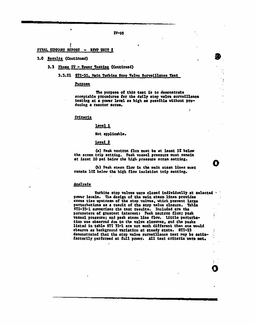
nV-ss
FINAL SCHWWY REPORTr - IPP UNIT 2
3.0 Results (Continued)
3.3 Phase IV - Power Testint (Continued)
3.3.£1 571-33. Main Turbine Stop Valvo Serveillene, Tost
Purpose
The purpose of this test La to demonstrate
acceptable procedures for the daily stop valve surveillasne
testing at a power level an high an possible without pro-
ducing a reactor scram.
Criteria
Ilevel 1
Bot applicable.
Level 2
(a) Peak neutron flux must be at least 5Z below
the scram trip setting. Peak vessel pressure must remain
at least 20 psi below the high-pressure scram setting. o(b) Peak steam flow In the vain steam lines must
remain 10% below the high flow Isolation trip setting.
Analysis
Turbine stop valves were closed individually at selected
power levels. The design of the main steam lines provides
cross ties upstream of the stop valves, which prevent large
perturbations as a result of the atop valve closure. Table
STI-33-1 summarixes ths test results. Included are the
parameters of greatest interest: Peak Mutron fluxt peak
vessel pressure; and peak steam line flow. Sittle perturba-
tion was observed due to the valve closures, and the peaks
listed In table STI 33-1 are not such different than on& would
observe as background variation at steady state. STI-33
demonstrated that the stop valve surveillance test may be satl-factorily performed at full pouer. All test criteria wer* met.
0

771W. SUX~tRY MOM~ - IM! UMI 2
3.0 Pim~tle (Ccutinved)
3.3DMT Powe~.r TesŽ!R& (Cmtiuued)
3.3.21 STI 33 Madin Turbin~e St Valve Surve111mkee Test (COutivued)
Table 971 33-1S MInm of 7wwbve, Stop Valve Closure Mata
Reactor Power 252 59.5? 74.9? 99.U
Peak, 1kutran Ylu 262 60.32 792 __________
flargin to L in t __ __ __ ____ __o%__ _ __ __ __ __ __
yeak essl Pteeawne 91.9 PSI 95 970 2gi 989 EdI
peak Stea LIM Flow L.0eb 2.25~n 2. &Mb- .Er Pr Br __ _ _ _
En nto Uvdt 752 48? 402
iofot that; data deow mw Peaec va7gve at each test Zepe?. 2%ie mmvin toUmfte am' d.$vamd by the falowfng trip 1"wta:
Weutron Fnii - Dependst on peakinig factor set LnVessel Pressurs - 1055 posgPeak Stem flow - 140? rated flow. , 4.7 M0b/lw

Iv-l00
FINAL 5MMRY REPORT - BYNIT 2
3.0 Results (Continued) k)
3.3 Phase TV - Power Testing (Continued)
3.3122 M-34. Vlbsation easurements
Pupose-.':
The purpose of this tast Is to obtain vibrationmeasurements on various reactor components to demonstrateths mechanical integrity of the system to flow Inducedvibrations and to check the validity and accuracy of theanalytical vibration model.
Criteria
Th vibration criteria, used to judge the resultsof the vibration measurements, is the pracalculated vibrationamplitude at each seansor when the maximum stress in any one ofthe internal's structures or components equals 10,000 psiincluding stress concentration factors. This stressrepresents approximately one halt the stress liilt given InASH! Code Section III for 40-year Uft. Because of theircomplexity the criteria are not presented here but will -4aevaluated by the CE vibration test engineer conductingthe taSte .
Jlnalysis
Vibration test data was taken in conjunction withthe recirculation pump trips, one pump at a time and then bothpumpa siultaneously,
Theme tests ware conducted at 50, 75, and 100 percentpower levals.
The General Electric Vibration 3peoialtst states thatthe vibration amplitudes are well within criteria U.imits. Afinal evaluation will be sade at a later date by the TVAcentral office staff or by an Independent consgltant-
M

FAL 8MMRY RUMT - FNP WIT 2
3.0 Results (Continued)
.1 Pzhase IV- Power Tostin (Continued)
3.3.23 911-35g Reirculation SLaUM Flow Calibration
Purposs
The purpose of this test Is to perform a completecalibration of the Installed recirculation system flowinstrumentation.
Criteria
Level I
Not applicable.
Lavel 2
(a) Jet pump flow Instrumentatton shall beadjuated such that the jet pump total floaw reorder wilprovide a correct core flouW.ndicatton. at rated conditions.
(b) The hIN/IZ ftowbisa AnstruantAttntz shallbe adjusted to function properly at rated conditions.
nalvuis
Racirculatton 6y7teu flow data wse taken on the5OZ 751, and lO0X flow control Una.. ledmdat datawas taken at each test condition end calculetionu were =4on each set, atiliaing the vendors' comPutor aytem(JPUWPS and RMPUPS prograna). The reaulta wVe analysedat each test condStion; howewvr Lgt.v4 uot npgassaiy tomake any instrument adjustments until ate4 cn4ittonu wvoreattained. At this point the data analysis revaed thit thQindicated recirculation flow was approwimately JQX hiAO thancalculated Values. Nov flow nUazia coefftoienta WV.determined basso on the caloautae vaves of flow UsuxR 9umchIractertstisu. Proa the nw nosale cost fiwinte, 5 am flowtransmitter calibration range was detormtns4.
Final caibration of th cr ow m wiftea nx spce-swas based on the date taken at rated anIitioPs . CompUORof the double tap jet pump flow vith the *eisn1 tap jt puoPflows slow that they mrs within apprpoubtoly U of 04b ahtv:,ft a4dition, the -ratios acrc wit~un Oe bond of # 0tP4theoretical values. The gin adjustant L4ntor 4Pn th-as-left ains are ts followst
.1 -0

P1-102
FWEAL SUQARiT RERT - 71 B 11211?I 2
3.0 Rout (Continued)
3*3 PhaseLtVV- LLwr L~singi (Continued)
3.3.23 STZ35, Recirculation System Zlow VAlISrTSOB (Coatlaued)Analysis (Coutinuad)
Inatruasut04an Adjustment An lieft
Imp mAMSSUULA 1.041 0.5205
a 1.04 0.52
The APMR)I/R) flow bias iustnw'muatation was fowidto perform it. function adequately at rated conditions*IROWAvar an unresolve4 problem was oncountc:.d ft thisarea. It was found that a non-41uea~1ty exists betwoanthe raoirculat$on flaw (drive glow) and the cote fMmvhitch causes prawature rod-Mockmi at low powev levlel. The(law bian instrumntationto,~S Set up at rated candit lonotUhou the flava are reduceds the nonw14neevity causes the 4ilveflow to decrease at a faster rate than the core flowscreatino a rod-bloc%~ condition. The, problex Uas not beensolved at this n.". kovevers the vendor hasi PTOPive.4 anotution and to prasoutly wm4srgoin vlain
.noevauato0
_______- - -

'V-103
FINAL SI Y REPORT - 8PP UN:S 2
3.0 Results (Coitlnued)
Mes TV Lm TetC (COntilhumd) ',''
3.3.24 STK.72. Drill Atmospherfe 6oollail 8Iuate
The juse oU6thie teot evCtiy t0e 4141ty2 of tb4 dM6l1 40108PUr4 4001114 47501 tO VAIM010,.:
desin condLttions 1 the drpoll 4ulr opetattus candittia".
' Nbn*#
(a) The b6t TronVul 0pabtlttf Of the doVM11. coolit omhil To opptmy4uAte1y S,9 X \ Stu/hw.
(b) ThM dr U goq1tag gyotim thaet bt*tv at^4dbyj ( 4ZapabtJ12ty of >~ 35S the 4,.p boat Wr~i4^ qBp a U~tv.
C() The dry t coooing oete,. hall vaInt4ta e-tvTp Ii the dimvU boiw he fo2Io0wS0 design v&u* 4'avlrsgpim oporattoiI.
JTlaaagml ftasctoy 0UtlI;'13S5 V. (57' ) CJ asva . itb Vdwout 4fwf-
#1 '. ):89 it 019*" go) "2da AX91lM the nTocia PV ,'50 .. 4tv bui14
'US'1 Ft (fill O) "40s" ao4t' the U11whe"
I tburs After thutdogW
M ISOu we (8,3' C,) of 01PRo^ qQ0149R.V~tfl ~t #tP~R'tVC IA RU *TeSe bsM*th thev^uss.to!twpgll bu14lbd, .
U -MM�

ZV-104
FINAL SnKMARY REPORT - BPNP UNIT 2
3.0 Results (Continued)
3,3 Phase TV. Power TdstiejU (Continued)
3.3.24 LTI-72. Drywall AteosphePIc Coolian Oysteim (Continued)
Critera (Continued)
Cooling Water SOpplyt
Uniform Circumfoeisuttel ;emperature at WJhitt~ thelRefueling DaollowsnBulkad Asnsm H1 ut La
. Anlaalnedt
*Within 25 P. maximum point-to-point variation
Analysis
At .002 power a1. points within the drywall wetthe 1SQ' P. maximum cepereture Criteria with the exceptionof TE-80-13 and TE-S0-14. The avorale drywall temperaturevan 124' 7. It alould be noted that RUCM temperature intothe drywatl vas 83.4' P, It to expe4ted that the Inlettemparature of RUC Into the drywall will approach lOS' T,during the sunmar months. At these conditions it indoubtful that dryuatt te"p#rst;re4 waoud meat design criteria.BED will evaluate and resolve thU problem.
The drywell heat loa4 was measured to be 6,11 x 10⁶Btu/hr at 100% pover, Thin coampres favorably with the designheat loa4 at 6,09 X 10⁶ Btu/hr with the drywall ausp pumpcooler out of service.
Date vas taken before and after one of the fultpower scravs to ittustrato the ability of the RBCCV nystea tohandle scram heat loads, Although at tan hours after thescram the average drywell temperature had act decreased towithin 15' P. of bhe BBCCW tote% temperaturea only a coolingcoafs and fans ware in servie -during thit time, Ten coilsan4 fans ware placed in oparitt# n and the temperaturedecreased to wsthin 15S F. of the RIUWCW inlet temperature,
,I
;

, FINAL BiJMAMIR RWORT -BnIP UNtT I
3.0 Resultm (Continued)
3.3 l- Ws Vov~erseli (Continued)
*3.5.25 SI-73. Caoliua water 523teuB
The 5purpoIs of this test to to verity that theperformeauc of the reactor bufldiug coseid codIluIR vate:(RDccu syateD La adequate, F
level I
Von&
(a) Verification that the platex perform'ance meWlthe cooling requiirements constUituts satisfacotry comu'je iCRof this test.
(b Ri'sCW woo dodlimod tip trsitofor m~a 1W5 -
load of 313 x 106 Iltus/r to ardor to ji4it sI114~ppot iLOU1~vtrtoinparoturo to lO00 u' it -4paii~R a ott~i~e (i;sv goog~ig)
iitet LAW vmerstuva Pt 09~ Fe
Tho hean land as mepawrOd a ths RPMV d olb #1A*
loAd on thpe~p pppl toolhet -- th-S-re. the RaCV pewohannsv Imit venufor rate wuld 4a vWt4n 32 of the Oaa4R avalve of 31t3 x t0 144thrt
NOu to atoept.a tp ae UU4P V IMOM SOP IrA 4419
ofthe drpol p ente it fp vtek usk~4%iw §Ms v p 'oe4nvet e
teupeRutur WM' flw,14 f rve fl ewu Ts dv~nedov tlVAIofO 0tfuI tT oM.tp'A 9115VSTJoprtr dMf Moitmo4Ors-~ 4
I
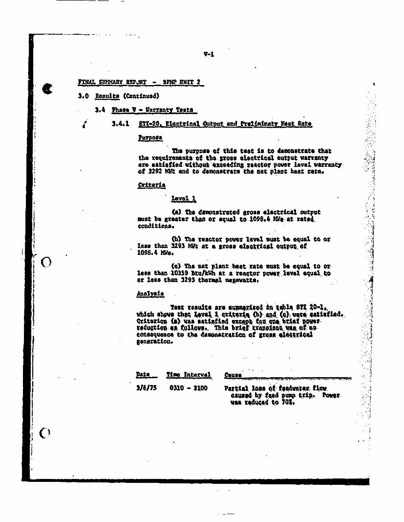
v-i
P JM MUR REPJ - 5?NP UNIT 2
3.0 Results (Continued)
3.4 Phase V- arranM Tests
3.4.1. OT*9?R EleUtricst A..Atut .. and ftel tt Feat Ratei--
mhe purpose of ths test Is to demonstrate thatth requirements of t - pose electrical output warvantye satifpod wethout exceeding zeetor r level warranty.
of 3292 )0t and to demonstrate the not plant beat rato.
Citeria,
level 1
(a) The demonstrated gross electrical outputmust be greter tho or squ4 t.o-1098.4 Wq-at rste4.conditions* -J
Cb) The reactor power laewl oust be equal to otless than 3293 HWt at a gross eoletdci4 ouput. of.1098.4 WeeW
(a) The tet plant he4t rate must be equal to or.less than 10359 BtulkWh at a reactor pmrjlvel qual toor less than 3293 thebrmi mewgavtte.
Analnsis
Tout results Fa s arw.Ax in tpal~q BTI ZO-,s,vhch show thnt J$vy 1 qr1tqrAx (b) -AMd. Co) war Utiad-Qviterion (a) was satit.fft4. exo k c t-ot av.r b 1e .w;,raduotton ep ~QUlpvs... This br1qf tra"pio4 t wt s otuoconsaquece to the dowansatiron¢ of gross. 41*4tia46quration. -;
Date Time Interval Cause
3/6/75 0310 - 2100 PatIa muant QI t o4vnr flow.caugg4 by- d4 pump trip. Powe.:was :qduosd to 70w-
I.,
I

V-2
J I
FTINAL SIICAY REPORT - BPNP UNIT 2
3.0 Results (Continued)
3.4 Ph.se V - VarrPnt Testa
3.4.1 SsT-20. U ectrteal OutPut and PrelimInary Vlat Rate
I-
Table STI 20-1ULecttLcal Output and Meat Rate test
Teat Intervml 300 Er (IJ
Corrected gross electrical output at 1114.2(2)generator terminals COM)
Assumed auxiliary load (coutractural-M#W) 24.4
Net generator output (KWe) 1089.8
Core thermal output (Ot) 327?
Not Plant Seat Rate (Btu/k'h) 10262
Net Plant EffiSciency (2) 33.26
(1) Aming the J00-how wmntj intemlrVc, on *inweqstia pawvduatie oaorwd.;
COveOHiMa0 1'e Mah fo, 42 OaWuIe 4.0t XM meter tq I9Aee va theOrmoP asuasred on the ientMoaZ unit I imtaRatQi*on o Sd by voleag, tme
r4 8 II oa the fOtIiO*s deVfanatin fr rated turbioenert0V
Warranty Condition Aotu 2
Condenser Lckpresuure (in Pfg abs) 1.47 t.
Poaer Pactor (mnitless) .9996 0.9
Cenrator Stator Coolant Pressure (pais) 49.44 55
C
(