Brown, A.J., Tikka, K., Daidola, J., Lutzen, M., Choe, I ...
27
Brown, A.J., Tikka, K., Daidola, J., Lutzen, M., Choe, I., "Structural Design and Response in Collision and Grounding", SNAME Transactions 108, pp. 447-473, 2000. Structural Design and Response in Collision and Grounding Alan Brown, Member, Virginia Tech, Kirsi Tikka, Member, Webb Institute, John C. Daidola, Fellow, AMSEC LLC, Marie Lützen , Student Member, Technical University of Denmark, Ick- Hung Choe , Student, Pusan National University Abstract The results summarized in this paper represent the work of SNAME Ad Hoc Panel #6 convened under the SNAME Technical and Research Program. This is a summary and overview paper. Topics discussed will be addressed individually and in more detail in later publications. The 2nd International Conference on Collision and Grounding of Ships, to be held in Copenhagen, July 1-3, 2001, will also present and discuss many of the results of this panel and other related research. The paper discusses four primary areas of panel work: collision and grounding models, data, accident scenarios and design applications. A probabilistic framework for assessing the crashworthiness of ships is presented. Results obtained from various grounding and collision models are compared to validating cases and to each other. Data necessary for proper model validation and probabilistic accident scenario development are identified. Deformable striking-ship bow models and their application are described. Potential design applications and alternatives for improving crashworthiness are discussed. 1 INTRODUCTION On May 14, 1998, SNAME Ad Hoc Panel #6, Structural Design and Response in Collision and Grounding, was formed under the SNAME T&R Steering Committee with support from the Hull Structure Committee, Ship Design Committee and Marine Safety and Environmental Protection Panel (O-44). The objectives of the panel are: • Investigate, compare and assess tools for predicting grounding and collision damage (including collision with ice). Emphasize simplified methods, which can be readily applied to the design and rapid analysis of new structural concepts, including applications using probabilistic scenarios. Finite element and other more rigorous methods may be considered and used to validate simplified methods. Include comparisons to available data. • Propose a format for a collision and grounding database. The database may include actual, experimental and simulated data as long as it is properly identified. Gather initial data. • Define standard scenarios and conditions for grounding and collision analyses. This may include probabilistic and/or deterministic descriptions of ship speed, trim, collision angle, striking ship displacement, striking ship bow characteristics, impact point, bottom, rock characteristics, rock height above baseline, sea state, ice mass, etc. • Define standard criteria and methodologies for applying structural performance in grounding and collision including oil outflow, carriage of nuclear waste, damaged stability, ultimate strength and serviceability. Provide a basis for performance specifications in these areas. • As tools, standard scenarios, methodologies and performance criteria are evaluated and defined, apply them to a matrix of typical and innovative structural designs and concepts. Identify promising concepts for future study. This paper is a summary report of work performed by the panel. It is the first of the deliverables specified in the panel’s charter. Additional papers and reports will follow. The panel has three working groups studying: 1) tools for predicting damage in grounding and collision; 2) collision and grounding scenarios; and 3) innovative design concepts. Funded research is centered at Virginia Tech and Webb Institute. The work of the panel, as presented in this paper, consists of four essential elements: • Benchmarking of grounding models Other Members of the Ad Hoc Panel contributing to this paper are: Donghui Chen Jeom Paik Bo Simonsen Surya Vakkalanka Ge Wang Rong Huang Rick van Hemmen John Sajdak Arne Stenseng Brett Fox Ryszard Kaczmarek Peter Gooding
Transcript of Brown, A.J., Tikka, K., Daidola, J., Lutzen, M., Choe, I ...

Brown, A.J., Tikka, K., Daidola, J., Lutzen, M., Choe, I., "Structural Design and Response in Collision and Grounding", SNAME Transactions 108, pp. 447-473, 2000.
Structural Design and Response in Collision and Grounding Alan Brown, Member, Virginia Tech, Kirsi Tikka, Member, Webb Institute, John C. Daidola, Fellow, AMSEC LLC, Marie Lützen, Student Member, Technical University of Denmark, Ick-Hung Choe, Student, Pusan National University
Abstract
The results summarized in this paper represent the work of SNAME Ad Hoc Panel #6 convened under the SNAME Technical and Research Program. This is a summary and overview paper. Topics discussed will be addressed individually and in more detail in later publications. The 2nd International Conference on Collision and Grounding of Ships, to be held in Copenhagen, July 1-3, 2001, will also present and discuss many of the results of this panel and other related research. The paper discusses four primary areas of panel work: collision and grounding models, data, accident scenarios and design applications. A probabilistic framework for assessing the crashworthiness of ships is presented. Results obtained from various grounding and collision models are compared to validating cases and to each other. Data necessary for proper model validation and probabilistic accident scenario development are identified. Deformable striking-ship bow models and their application are described. Potential design applications and alternatives for improving crashworthiness are discussed.
1 INTRODUCTION On May 14, 1998, SNAME Ad Hoc Panel #6, Structural Design and Response in Collision and Grounding, was formed under the SNAME T&R Steering Committee with support from the Hull Structure Committee, Ship Design Committee and Marine Safety and Environmental Protection Panel (O-44). The objectives of the panel are:
• Investigate, compare and assess tools for predicting grounding and collision damage (including collision with ice). Emphasize simplified methods, which can be readily applied to the design and rapid analysis of new structural concepts, including applications using probabilistic scenarios. Finite element and other more rigorous methods may be considered and used to validate simplified methods. Include comparisons to available data.
• Propose a format for a collision and grounding database. The database may include actual, experimental and simulated data as long as it is properly identified. Gather initial data.
• Define standard scenarios and conditions for grounding and collision analyses. This may include probabilistic and/or deterministic descriptions of ship speed, trim, collision angle, striking ship
displacement, striking ship bow characteristics, impact point, bottom, rock characteristics, rock height above baseline, sea state, ice mass, etc.
• Define standard criteria and methodologies for applying structural performance in grounding and collision including oil outflow, carriage of nuclear waste, damaged stability, ultimate strength and serviceability. Provide a basis for performance specifications in these areas.
• As tools, standard scenarios, methodologies and performance criteria are evaluated and defined, apply them to a matrix of typical and innovative structural designs and concepts. Identify promising concepts for future study.
This paper is a summary report of work performed by the panel. It is the first of the deliverables specified in the panel’s charter. Additional papers and reports will follow. The panel has three working groups studying: 1) tools for predicting damage in grounding and collision; 2) collision and grounding scenarios; and 3) innovative design concepts. Funded research is centered at Virginia Tech and Webb Institute.
The work of the panel, as presented in this paper, consists of four essential elements:
• Benchmarking of grounding models
Other Members of the Ad Hoc Panel contributing to this paper are: Donghui Chen Jeom Paik Bo Simonsen Surya Vakkalanka Ge Wang Rong Huang Rick van Hemmen John Sajdak Arne Stenseng Brett Fox Ryszard Kaczmarek Peter Gooding

2
• Benchmarking and development of collision models
• Definition of grounding and collision scenarios including striking bow geometry and bow stiffness.
• Innovative design concepts
2 MOTIVATION The serious consequences of ship grounding and collision necessitate the development of regulations and requirements for the subdivision and structural design of ships to reduce damage and environmental pollution, and improve safety.
The International Maritime Organization (IMO) is responsible for regulating the design of oil tankers and other ships to provide for ship safety and environmental protection. Their ongoing transition to probabilistic performance-based standards requires the ability to predict the environmental performance and safety of specific ship designs. This is a difficult problem requiring the application of fundamental engineering principles and risk analysis.
IMO first introduced probabilistic standards in damage stability regulations for passenger ships [1] and later for cargo ships [2]. IMO’s first attempt to apply a probabilistic methodology to tankers was in response to the US Oil Pollution Act of 1990 (OPA 90). In OPA 90 the US required that all oil tankers entering US waters must have double hulls. IMO responded to this unilateral action by requiring double hulls or their equivalent. Equivalency is determined based on probabilistic oil outflow calculations specified in the "Interim Guidelines for the Approval of Alternative Methods of Design and Construction of Oil Tankers Under Regulation 13F(5) of Annex I of MARPOL 73/78” [3], hereunder referred to as the Interim Guidelines.
All of these regulations use probability density functions (pdfs) to des cribe the location, extent and penetration of side and bottom damage. These pdfs are derived from limited historical damage statistics [4], and applied identically to all ships without consideration of their structural design. Figure 1 is the IMO probability density function used to define the longitudinal extent of bottom damage from grounding in oil outflow calculations. The histograms represent the statistical data collected by the classification societies and the linear plot represents IMO's piece-wis e linear fit of the data. Other IMO pdfs are constructed in a similar manner.
0.5
0.5
4.5
0.0
1.0
2.0
3.0
4.0
5.0
0.0 0.1 0.2 0.3 0.4 0.5 0.6 0.7 0.8
Damage Length/Ship Length
Pro
bab
ilit
y D
ensi
ty
Tanker Data - 63 Cases
Piecewise Linear Fit
fb2LONGITUDINAL EXTENT FOR BOTTOM DAMAGE
Figure 1 - Damage Probability Density Function [4]
A major shortcoming in IMO’s current oil
outflow and damage stability calculation methodologies is that they do not consider the effect of structural design or crash-worthiness on damage extent [5,6]. The primary reason for this exclusion is that no definitive theory or data exists to define this relationship.
Other deficiencies include:
• Damage pdfs consider only damage significant enough to breach the outer hull. This penalizes structures able to resist rupture.
• Damage extents are treated as independent random variables when they are actually dependent variables, and ideally should be described using joint pdfs.
• Damage pdfs are normalized with respect to ship length, breadth and depth when damage may depend to a large extent on local structural features and scantlings vice global ship dimensions. It is logical and essential that crashworthiness is
considered in oil outflow and damage stability calculations. An analytical method is required to define the relationship between structural design and damage extent in collision and grounding. This is a primary objective of the work of this panel.
A method that considers crashworthiness must be sensitive to at least the basic parameters defining unique structural designs while maintaining sufficient generality and simplicity to be applied by working engineers in a regulatory context for a ship in worldwide operation. It should not require detailed finite element analysis or be limited to a single accident scenario.
An additional advantage of performance-based models is the potential for their application to different and innovative designs. This is a second primary objective of this panel.

3
3 PROBABILISTIC FRAMEWORK Figure 2 illustrates the process proposed to predict the probabilistic extent of damage in collision as a function of ship structural design [7]. A similar process is proposed for grounding.
Struck ship design variables: Type (SH,DH,IOTD,DS,DB,DS) LBP, B, D Speed & displacement Subdivision Structural design
Probability given collision Point puncture, raking puncture, penetrating collision Pdf's: Striking ship speed Striking ship displacement Striking ship draft & bow height Striking ship bow shape and stiffness Collision striking location & angle
Monte Carlo Simulation
Extent of Damage
CalculationSpecificcollisionscenario's
Regression analysis
joint pdf for longitudinal, vertical and transverse extent of damage:
Pdf parametrics for extent of damage as a function of struck ship design
Figure 2 - Process to Predict Probabilistic Damage [7]
The process begins with a set of probability density functions (pdfs) defining possible grounding or collision scenarios. Using these pdfs, a specific scenario is selected in a Monte Carlo simulation, and combined with a specific ship structural design to predict damage. This process is repeated for thousands of scenarios and a range of structural designs until sufficient data is generated to build a set of parametric equations relating probabilistic damage extent to structural design. These parametric equations can then be used in oil outflow or damage stability calculations.
DAMAGE Generated Points
MARPOL Standard
0 0.2 0.4 0.6 0.8 1-2
0
2
4
6
8
10
12Bottom Damage Longitudinal Extent PDF
Length of Damage / Ship Length
4.5
0.5
0.5
Figure 3 – Bottom Damage pdf [6]
A damage pdf generated in an early application of this approach is shown in Figure 3 [6]. This pdf was generated for a MARPOL single hull tanker typical of the struck ships represented in the data used to develop the current MARPOL damage pdfs.
4 GROUNDING MODELS
4.1 Background and Plan The Exxon Valdez accident in 1989 and the regulatory events following it lead to active research on structural behavior in grounding. The earlier studies had been mostly empirical, the best-known being a study by Card [8] who surveyed 30 grounding incidents to determine the effectiveness of a double bottom in reducing pollution. More recent studies have included large numerical simulations, small and large scale experiments, and the development of simplified methods. Many of these studies were supported by the project “Protection of Oil Spills from Crude Oil Tankers” carried out by the Japanese Association for the Structural Improvement of Shipbuilding Industry (ASIS). In the United States, the Carderock Division of the Naval Surface Warfare Center (NSWCCD) conducted grounding experiments, and the MIT-Joint Industry Project on Tanker Safety developed software to analyze structural damage in grounding. Development of analytical models for the software was supported by experimental studies. Active research effort on grounding analysis has been carried out also in Europe, mainly in Denmark and the Netherlands.
The Specialist Panel V.4 of the 1997 International Ship and Offshore Structures Congress (ISSC 1997) [9] reviewed the state-of-the-art of the research and concluded that nonlinear finite element analysis coupled with calculation of ship motions had reached a level at which a fairly accurate prediction of the structural response was possible. However, the report noted that since the method is time consuming and requires a high-level of expertise, it is not suitable for the design or regulatory environment. The report also concluded that the simplified methods that existed at the time required further validation.
This study concentrates on evaluation of the existing simplified methods, which have been further developed since the ISSC 1997 report. The objective is to assess their suitability for design and regulatory work.
4.2 Models Included in the Current Study The methods evaluated in this study include DAMAGE, a software tool developed by the MIT-Joint Industry Project on Tanker Safety, and a simple analytical method developed by Dr. Wang at the University of Tokyo (method by Wang). Both methods calculate grounding

4
force and extent using closed-form solutions, but they differ in the detail in which the structure is defined and its behavior is analyzed. The methods also differ in their treatment of ship motions. The program DAMAGE was selected for further testing and analysis, because it is applicable for a wider range of grounding scenarios.
4.2.1 DAMAGE [10] The computer program DAMAGE was developed at MIT under the Joint MIT-Industry Program on Tanker Safety. This project, lead by Professor Tomasz Wierzbicki, was initiated in 1991, and in addition to the program DAMAGE the project has produced more than 70 technical reports about prediction of grounding and collision damage. The program DAMAGE Version 5.0 can be used to predict structural damage in the following accident scenarios:
• Ship grounding on a conical rock with a rounded tip (rigid rock, deformable bottom)
• Ship-ship collision (deformable side, deformable bow)
Compared to previous models for prediction of grounding and collision damage, a major advantage of DAMAGE is that the theoretical models are hidden behind a modern graphical user interface (GUI) [10]. The program has been developed with the objective of making crash analysis of ship structures feasible for engineers that do not have any particular experience in the field of crashworthiness. Figure 4 shows the input screen for defining the “ship-ground interaction”, the relative position and velocity of ship and ground, coefficient of friction, etc.
Figure 4 - Input screen for defining the “Ship-ground
Interaction” in the program DAMAGE [10]
Initially, the ship is assumed to be on a straight-line course with a known velocity and trim. The rock is at some distance to port or starboard of the ship’s centerline, and at some height above the ship’s baseline. During the
event, the contact force between ship and ground induces heave, roll and pitch motion on the ship, and eventually causes the ship to stop.
The primary mechanisms of energy dissipation are:
1. A change in potential energy of the ship and the surrounding water as the ship is lifted by the ground reaction.
2. Friction between the ground and hull.
3. Deformation and fracture of the hull.
Since the lifting of the ship off the rock generally causes a reduction in crushing and tearing forces it is important to include the coupling between the global ship motions (external dynamics) and the local damage process (internal mechanics). Detailed descriptions of the model for the external dynamics can be found in References [11] and [12].
For the model to be applicable to optimization for structural crashworthiness it is important that it captures the effect of :
• Material strength and ductility • Dimensions and arrangement of major structural
components such as bulkheads, decks, girders and large stiffeners.
The theoretical model is based on a set of super-element solutions, i.e. closed form, analytical solutions for the energy absorption of rather large structural components undergoing large deformations. All structural components are assumed to follow the same overall mode of deformation around the rock. This way it is possible to take into account the structural resistance of all typical members in a ship bottom. The fracture criterion is based on analytical solutions for plastic response of a membrane. Figure 5 shows a window from an animation of the ship motion over the rock.
A description of the procedure including detailed derivations of the super-element solutions can be found in References [13] and [14].
Figure 5. DAMAGE simulation of ship motion over a
rock (only selected structural elements are shown).

5
4.2.2 Method by Wang [15] Dr. Wang developed a method to predict structural resistance in raking type grounding in his doctoral work under Professor Hideomi Ohtsubo’s supervision. The method was further developed and published in 1997 [15].
Figure 6 - Four Failure Modes in the Method by Wang
The method includes closed-form solutions for four
failure modes: stretching (beam mode), denting, tearing and concertina tearing illustrated in Figure 6.
The rock is modeled as a wedge, and the ship’s bottom structure is modeled with periodic structural members where the period corresponds to transverse frame spacing. Only horizontal ship motions are considered in the calculation.
The grounding damage is calculated by combining the failure modes to model periodic resistance of the structure. The resistance of the transverse structure is predicted with a beam model. The denting failure mode is assumed for the plate immediately behind the transverse structure. As the wedge advances in the plating and a crack develops at the tip of the wedge, the rupture is modeled by tearing failure mode. Concertina tearing is used to model the accordion like behavior of the plating, which can lead to cracks at other locations than the tip of the wedge. The entire calculation can be carried out by hand or with a simple spreadsheet program, but the analyst must decide how the failure modes are combined to achieve the final damage.
4.3 Application DAMAGE was selected for further testing and analysis, because of its applicability to a wider range of grounding scenarios. Although the method by Wang is elegant in its simplicity, its application in the current formulation is limited to raking type damage only. The major limitations of the current version of DAMAGE are the
type of obstruction (pinnacle only), and the structural model (the structure is modeled for the cargo block only).
4.3.1 Validation of DAMAGE Simonsen presented verification of the theory behind DAMAGE models by comparing calculated results with US NAVY 1/5-scale grounding experiments, with large-scale grounding experiments carried out in the Netherlands, and with an actual grounding of a VLCC [14,16].
Based on the limited number of validation cases DAMAGE is found to predict the damage extent well. In the case of a VLCC grounding, the difference between the calculated damage length of 177 meters and the observed damage length of approximately 180 meters is only 1.7%. The result is sensitive to the transverse location of the rock relative to the ship’s centerline as is illustrated in Figure 7. As the rock moves away from the centerline the effect of ship motions increase and the predicted damage length increases.
DAMAGE predictions for average rock penetration and grounding force are also excellent. Predictions for minimum and maximum values are not as good. Figures 8-10 illustrate a comparison of DAMAGE results with a large-scale grounding test carried out in the Netherlands by ASIS. Large differences in the penetration at the initial stages of grounding are probably due to simplifications in the global motion calculations.
2
3
4
5
-50 0 50 100 150
Longitudinal Position (m)
Roc
k Pe
netr
atio
n (m
)
e=0
e=5
e=10
Figure 7 - Rock Penetration vs. Rock Eccentricity
0
0.2
0.4
0.6
0.8
1
1.2
1.4
0 0.5 1 1.5 2 2.5 3
Time (sec)
Ver
tical
Pen
etra
tion
(m)
DAMAGE Measured
Figure 8 - Vertical Penetration (ASIS Test 2)

6
0
0.5
1
1.5
2
2.5
3
0 0.5 1 1.5 2 2.5 3
Time (sec)
Hor
izon
tal F
orce
(MN
)DAMAGE Measured
Figure 9 - Comparison of Horizontal Forces (ASIS Test
2)
0
0.5
1
1.5
2
0 0.5 1 1.5 2 2.5 3
Time (sec)
Ver
tical
For
ce (
MN
)
DAMAGE Measured
Figure 10 - Comparison of Vertical Forces (ASIS Test 2)
Figure 11 - Sketch of Four Grounding Scenarios
4.3.2 Sensitivity Analysis The sensitivity of DAMAGE results to changes in grounding parameters was studied and presented in [17]. The base ship used in the sensitivity analysis was a 237,000 DWT single-hull VLCC and the grounding case studied corresponded to the VLCC validation case.
In the sensitivity analysis only one parameter was changed at the time and the other parameters were kept at their initial values. The objective of this analysis was not to study the effect of the structural design on the damage
extent, rather the objective was to investigate the sensitivity of the DAMAGE model to the parameters defining the grounding event.
As can be expected the results are very sensitive to the ground characteristics and to the parameters defining the ship-ground interaction (rock elevation, rock shape and transverse location, ship velocity and displacement, friction coefficient and trim angle).
The parameters affecting the global ship motions (longitudinal center of floatation and the longitudinal and the transverse metacentric height) had little effect on

7
damage results. Surprisingly, the tank spacing as well as the characteristics of both the transverse bulkhead and the longitudinal bulkhead had very little effect on damage results. The results were also not very sensitive to material characteristics.
Damage results were sensitive to the thickness of the outer bottom. Reducing the spacing and increasing the scantlings of longitudinal girders and transverse floors also affected damage results, but not as effectively. The same applied to longitudinal stiffeners.
4.3.3 Structural Modifications
DAMAGE was found to provide a good tool for comparative studies based on the validation cases and the sensitivity analysis. The next step in the study was to investigate the effect of structural modifications on the damage extent in selected grounding scenarios. The study was limited to eight grounding scenarios, and the structural changes were limited to changes in scantlings of a conventional double-bottom structure. The analysis was intended to provide insight into the effects of the modifications and scenarios to help design a probabilistic analysis, which will be the next step in the study.
The base ship used in the analysis was a 150,000 DWT double-hull tanker. The grounding scenarios were selected to represent high, medium and low rock elevations relative to the ship’s baseline. One of the scenarios had a sharp rock tip (30 degree semi -apex angle), whereas the shape of the rock was kept constant in the other scenarios (45 degree semi-apex angle). Two velocities were analyzed: 7 knots to represent port speed and 14 knots to represent service speed of the tanker. The rock shapes and elevations are illustrated in Figure 11. More details on the base ship and the grounding scenarios can be found in [17].
Eight structural modifications, all designed according to the requirements of ABS SafeHull (97/98), where investigated. The scantlings met the minimum requirements except for the dimension under investigation. The modifications included:
1. Increase in the outer bottom plate thickness.
2. Increase in the inner bottom plate thickness.
3. Increase in both outer bottom and inner bottom plate thickness.
4. Additional longitudinal girder.
5. Two additional longitudinal girders.
6. Reduced spacing of transverse floors.
7. Decrease in double bottom height.
8. Increase in double bottom height.
The steel weight (longitudinal structure only) was calculated for each design, and the effectiveness of a design modification was measured in terms of the reduction in inner bottom rupture as a function of the steel weight. Changes in the transverse structure caused by the modifications were not taken into account.
Some conclusions based on the selected scenarios include: • In the low rock elevation case, which represents
raking type grounding, none of the designs had inner bottom rupture. At service speed the outer bottom ruptured throughout the entire length of the ship. In this type of scenario, the structural modifications have little impact on the damage extent and no effect on the oil outflow assuming that the vessel survives the raking damage.
• In the sharp rock tip, high-rock elevation case the rock penetrated through the entire cargo block in all designs at service speed. Even at port speed all designs had serious damage. However, increased outer bottom or inner bottom thickness, two additional girders, or reduced spacing of transverse floors did reduce outer bottom and inner bottom rupture. This was the only grounding scenario where increasing double bottom height had very little effect on the inner bottom rupture.
• In high and medium rock elevation cases most of the design modifications improved structural performance. Reducing the double bottom height resulted in the worst performance. The design with two additional longitudinal girders performed best in reducing inner bottom rupture, but it also had the heaviest steel weight among the studied designs. If the steel weight was taken into account, increasing the thickness of the outer bottom was found to be most effective in reducing the inner bottom rupture. Increasing both the inner bottom and outer bottom thickness reduced the inner bottom rupture more but at the cost of a higher steel weight.
4.4 Ongoing and Future Work The work discussed above was carried out to provide a basis for a probabilistic analysis, which will take into account a range of possible grounding scenarios. However, to add credibility to the results further validation is needed. Data needs for validation work will be discussed later in the paper. Further review of the results from the presented validation cases is ongoing.
The analysis on the effect of structural modifications discussed above measured the performance in terms of the damage extent without taking into account the subdivision of the vessel. Therefore the observed changes in the damage extent may have no effect on the resulting oil outflow. To determine the effect of the structural

8
modifications on oil outflow the DAMAGE calculations should be coupled with outflow analysis.
The next step in the study is to carry out a probabilistic analysis of damage in grounding scenarios defined by probability density functions of the input parameters. This analysis will be coupled with outflow calculations. The objective of the study will be to provide a tool for comparative studies between vessel designs.
5 COLLISION MODELS
5.1 Background and Plan In 1979, the Ship Structure Committee (SSC) conducted a review of collision research and design methodologies [18]. They concluded that the most promising simplified collision analysis alternative was to extend Minorsky’s original analysis of high-energy collisions by including consideration of shell membrane energy absorption. A simple and fast model is important in probabilistic analysis because thousands of different scenarios must be run to develop statistically significant results.
A more recent review of the literature and of the applicability of available methods for predicting structural performance in collision and grounding was made in the 1997 International Ship and Offshore Structures Congress (ISSC 97) by Specialist Panel V.4 [9]. Their report states: “Knowledge of behavior on a global level only (i.e., total energy characteristics like the pioneering Minorsky formula) is not sufficient. The designer needs detailed knowledge on the component behavior (bulkheads, girders, plating, etc.) in order to optimize the design for accident loads.”
The approach taken in this study is to progressively increase the complexity of SIMCOL (Simplified Collision Model), the Ad Hoc Panel’s baseline collision model, until results with sufficient accuracy and sensitivity to design characteristics are obtained. In order to assess the model’s consistency and sensitivity, the model is applied in a series of collision scenarios with a range of tanker sizes and designs. SIMCOL results are compared to results obtained using three other collision models: DAMAGE [10,19], ALPS/SCOL [20,21], and a Technical University of Denmark (DTU) model. The DTU model and ALPS/SCOL were also further developed during this study. Determining the ideal trade-off between simplicity and sufficiency is a primary concern of this process.
5.2 Models Included in the Current Study Three types of collision were identified for investigation by the panel: • Low energy puncture at a point
• Low energy raking puncture • Penetrating Collision – right angle and oblique
sufficient to penetrate outer hull with significant damage extending in at least 2 directions (penetration, horizontal, vertical)
Work thus far is focused on models for penetrating collision.
Each collision model must consider two very different aspects of the collision event: • External problem – includes the global
characteristics of the striking and struck ships and their motion before, during and after collision;
• Internal problem - includes the internal deformation mechanics and structural response of the struck ship and the striking ship bow during collision.
The four models studied by the panel take different approaches to solving and coupling these two problems. Although not a formal validation, comparison and agreement between these models provides useful insight into their performance and increases confidence in the validity of their results.
5.2.1 Simplified Collision Model (SIMCOL) [22]
SIMCOL uses a time -domain simultaneous solution of external dynamics and internal deformation mechanics similar to that originally proposed by Hutchison [23]. Figure 12 shows the SIMCOL simulation process. The external sub-model uses a three degree-of-freedom system for ship dynamics shown in Figure 13. The internal sub-model determines reacting forces from side and bulkhead structures using detailed mechanisms adapted from a 1981 Rosenblatt study [24,25]. It determines the energy absorbed by the crushing and tearing of decks, bottoms and stringers using the Minorsky correlation [26] as modified by Reardon and Sprung [27].
At time step i
Based on current velocities, calculate thenext positions and orientation angles of the
ships, and the relative motion at impact
Calculate the change of impact locationalong the struck ship and the increment of
penetration during the time step
Calculate the average reaction forces duringthe time step by internal mechanisms
Calculate the average accelerations of bothships, the velocities for the next time step,
and the lost kinetic energy based on externalship dynamics
Go to the next time step:i = i+1
Meet stoppingcriteria ?
Calculate maximumpenetration and damage
length
YesNo
Figure 12 - SIMCOL Simulation Process

9
x
y
θ1
φStriking Ship
Struck Ship
θ2
l
Note: The positive direction of angle is alwayscounterclockwise.
G1
G2
Figure 13. SIMCOL External Ship Dynamics
V.U. Minorsky conducted the first and best known of
the empirical collision studies based on actual data [26]. His method relates the energy dissipated in a collision event to the volume of damaged structure. Actual collisions in which ship speeds, collision angle, and extents of damage are known were used to empirically determine a linear constant. This constant relates damage volume to energy dissipation. In the original analysis the collision is assumed to be totally inelastic, and motion is limited to a single degree of freedom. Under these assumptions, a closed form solution for damaged volume can be obtained. With additional degrees of freedom, a time-stepped solution must be used.
Crake and Brown developed SIMCOL Version 0.0 as part of the work of SNAME Ad Hoc Panel #3 [6,28]. Based on further research, test runs and the need to make the model sensitive to a broader range of design and scenario variables, improvements were progressively made by Chen and Brown at Virginia Tech [22]. A sweeping segment method, shown in Figure 14, is added to the model in SIMCOL Version 1.0 to improve the calculation of damage volume and the direction of damage forces. Models from the Rosenblatt study [24,25] are applied in Version 1.1 assuming rigid web frames. In Version 2.0, the lateral deformation of web frames is included as shown in Figure 15. In Version 2.1, the vertical extent of the striking ship bow is considered. Table 1 describes the evolution of SIMCOL over the course of the study thus far.
Design data required for the striking ship includes bow half-entrance angle, bow height, length, beam, draft and displacement.
Scenario data required includes striking and struck ship velocity, collision angle, and longitudinal location of impact in the struck ship.
beginning of time step n
end of time step n
damaged area duringtime step n
η
Striking Ship
Struck Ship
ξ side shellP4,n, P5 ,n
P4,n+1, P5,n+1 P1,n P1,n+1
P2,n
P2,n+1
P3,n+1
P3,n
φ′n
α
Figure 14. Sweeping Segment Method
Web frames acting as a vertical beamdistort in bending, shear or compression
Strike at webframe
Strike betweenweb frame
Analyze each shellseparately
consistent withweb deformation.
Analyze each shellseparately withnodes consistent
with webdeformation.
Figure 15. Web Deformation in SIMCOL 2.0 [24,25]
5.2.2 DAMAGE 4.0 [19] The DAMAGE 4.0 collision module solves the external problem uncoupled from the internal problem, and applies the calculated absorbed energy to plastic deformation of the struck ship. Structural components, motions, masses etc. are described in ship coordinate systems local to each ship and in one global coordinate system. Degrees of freedom in DAMAGE include striking ship surge and struck ship sway and yaw.
The following assumptions are applied in DAMAGE 4.0: • Both ships are perpendicular before and during
impact, i.e. only right angle collisions are considered. • The forward motion of the struck ship is assumed to
be zero.
10
Table 1. SIMCOL Evolution
Version 0.1 1.0 1.1 2.0 2.1
Simulation Simulation in time domain
External Model Three degrees of freedom(Hutchison and Crake)
Minorsky mechanism as re-validated by Reardon and SprungHorizontalMembers
Crake’smodel
Sweeping segment method to calculate damaged areaand resulting forces and moments
Jones and Van Mater McDermott / Rosenblatt Study methodsVerticalMembersw/o ruptureof plate
Crake’smodel(Jones)
VanMater’s
extensionof Jones
Does notconsiderdeforma-tion ofwebs,
frictionforce and
the force topropagateyielding
zone
Considersdeforma-tion ofwebs,
frictionforce and
the force topropagateyielding
zone
Strikingbow withlimiteddepth
Inte
rnal
Mod
el
VerticalMembersw/ rupturedplate
Neglected Minorsky method forcalculating absorbed
energy due tolongitudinal motion
In DAMAGE 4.0, the striking ship bow is assumed to
be rigid. DAMAGE Version 5.0 (Released June 2000) includes crushing of the bow.
Based on conservation of linear momentum, angular momentum and energy, the velocities after the impact are calculated as well as the loss of kinetic energy, which is available for the structural deformations.
In order to determine the deformation of the bow and the side, the striking ship is moved into the struck ship in small increments. In each increment, the total resistance forces from crushing of the bow and penetration into the side are compared. The actual crushing/penetration increment takes place in the ship with lowest resistance.
DAMAGE 4.0 considers the material and structural scantlings of all major structural components for the side structure.
1
5
9
13
S1
S3
S5 S7
S9 S11 S
13 S15
0.00E+00
2.00E+00
4.00E+00
6.00E+00
8.00E+00
1.00E+01
1.20E+01
1.40E+01
1.60E+01
1.80E+01
Figure 16. DAMAGE Bow Geometry
The model for the internal mechanics is based on the direct contact deformation of super-elements. The super-elements used to model the side in DAMAGE are:
• Shell and inner side plating (laterally loaded plastic membrane)
• Deck and girder crushing • Beam loaded by a concentrated load • X-, L- and T-form intersections crushed in the
axial direction
The bow geometry is defined by eight parameters. Figure 16 shows an example the bow geometry.
5.2.3 ALPS/SCOL ALPS/SCOL is a coarse-mesh 3-D non-linear finite element code using super-elements based on the Idealized Structural Unit Method (ISUM) [20,21]. The geometry of the striking and the struck ships is described in a global (three-dimensional) rectangular coordinate system. The stress in an ISUM unit is described in a local element coordinate system. ALPS/SCOL considers sway and yaw of the struck ship with the following assumptions: • The added masses of the striking and the struck ships
are calculated based on ships of similar type and size using a linear strip theory-based computer program.
• The striking ship is assumed to be rigid. • The analysis of the external and the internal
dynamics is undertaken separately. • The longitudinal velocity of the struck ship is not
considered. • Since ALPS/SCOL is based on a simplified 3-D
nonlinear finite element approach, damage in the three directions (i.e., including penetration, vertical and horizontal damage) are considered.
• The geometry of the striking ship bow shape is described by gap/contact elements. The bow is assumed to be rigid.
• One cargo hold of the struck ship is taken as the extent of the analysis.
• ISUM stiffened panel units are used to model the struck vessel structure.
The geometry of the struck ship is described using about 600 rectangular or triangular ISUM units. If the deformation of the struck ship is symmetric, the total degrees of freedom in the numerical model are reduced by half. Each node has 3 degrees of freedom.
Figure 17 shows damage calculated in an ALPS/SCOL simulation.
Design data required for the striking ship includes a detailed bow geometry description, length, beam, depth, draft and displacement.
Design data for the struck ship includes, length, beam, depth, draft and displacement, transverse bulkhead

11
location, COG, and detailed structural design and scantlings.
Scenario data required includes striking ship velocity and longitudinal location of impact in the struck ship.
Figure 17. Damage from ALPS/SCOL Simulation
5.2.4 DTU Model
The Technical University of Denmark (DTU) model also solves the external problem uncoupled from the internal problem, and applies the calculated absorbed energy to plastic deformation of the struck ship.
Solution of the external dynamics is accomplished based on an analytical method developed by Pedersen and Zhang [29]. This method estimates the fraction of the kinetic energy that is available for deformation of the ship structure. The energy loss for dissipation by structural deformation is expressed in closed-form expressions. The procedure is based on a rigid body mechanism, where it is assumed that there is negligible strain energy for deformation outside the contact region, and that the contact region is local and small. This implies that the collision can be considered instantaneous as each body is assumed to exert an imp ulsive force on the other at the point of contact. The model includes friction between the impacting surfaces so those situations with glancing blows can be identified. Both ships have three degrees of freedom: surge, sway and yaw. The interaction between the ships and the surrounding water is approximated by simple added mass coefficients, which are assumed to remain constant during the collision.
The loss in kinetic energy by the method is determined in two directions, perpendicular and parallel to the side of the struck ship. Both right and oblique angle collisions are considered and both vessels may have velocity before the collision.
Ship-Ship collision
0
0,2
0,4
0,6
0,8
1
-0,5 -0,3 -0,1 0,1 0,3 0,5
Collision location (d/L)
Ene
rgy
ratio
60 Deg.90 Deg.120 Deg.150 Deg.
Figure 18 - Energy ratio defined as the ratio between energy released for crushing and the total kinetic energy of the two ships before the collision as function of the collision location, d, for collision angles equal 60, 90, 120 and 150 degrees. The two tankers are identical and have the same speed prior to the collision [29].
The model for the internal mechanics is based on a set of super-elements, where each element represents a structural component. The calculation method is based on the principle that the area of the struck vessel affected by the collision is restricted to the area touched by the striking vessel. The super-elements are: • Lateral plate deflection and rupture. Large
deflections are assumed; this implies that the bending resistance can be neglected
• Crushing of structure intersection elements (X- or T-elements)
• In-plane crushing and tearing of plates • Beam deflection and rupture
The design data for the struck vessel includes length, beam depth, draft, displacement, COG and detailed structural design and scantlings.
The bow of the striking vessel is assumed to be rigid. The basic data for describing the striking ship bow are stem angle, breadth and bow height. The horizontal shape of the deck and the bottom are assumed to be parabolic. If the striking vessel is equipped with a bulb, this is assumed to have the form of an elliptic parabola.
Scenario data required includes striking and struck ship velocity, collision angle and longitudinal location of impact at the struck vessel.
5.3 Application In order to assess the models’ consistency and sensitivity, they are tested in a series of collision scenarios with a range of struck tanker sizes and designs. The Baseline Tanker design is a 150000 dwt double-hull tanker. It was developed to be consistent with the dimensions of the 150000 dwt reference tanker in the IMO Interim Guidelines. HECSALV and SafeHull were used to

12
develop the details of the design, and to insure that the arrangement satisfies IMO regulations and the structural design satisfies ABS classification requirements. A 60000 dwt double hull tanker and a 283000 dwt double tanker were also developed in accordance with the Interim Guidelines [3]. Results for the baseline 150000 dwt double-hull tanker are presented in this paper.
5.3.1 Struck Ship The 150000 dwt Baseline Tanker design shown in Figure 19 is the primary struck ship used for the initial model testing. Tables 2 and 3 list principal characteristics and structural data for this design.
Table 4 lists the input data for each test matrix. The first test matrix considers damage for a series of strike locations on the web at the center of each cargo tank. This represents a large global variation in strike location. The second test matrix considers damage for a series of strike locations on either side of the web at the center of the midship cargo tank. This represents a relatively small local variation in location on and between webs. The third test matrix considers damage for a series of collision angles with a strike location on the web at the center of the midship cargo tank.
Figure 19 - Baseline Tanker Design [3]
Table 2. Baseline Tanker Principal Characteristics
Deadweight, tonnes 150,000
Length L, m 264.00
Breadth B, m 48.00
Depth D, m 24.00
Draft T, m 16.80
Double Bottom Ht hDB, m 2.32
Double Hull Width W, m 2.00
Displacement, tonnes 178,867
5.3.2 Model Test Matrices Three scenario test matrices were used in the initial study. All matrices use the Baseline Tanker as the struck ship and a 150000 dwt bulk carrier as the striking ship. Principal characteristics for the striking ship are listed in Table 4 and the resulting vertical alignment of the two ships is shown in Figure 20. Since the focus of the initial tests is on penetration damage, zero struck ship speed is used in all cases. Scenarios for the test matrices are described in Table 5.
Table 3. Baseline Tanker
Ship 150,000 dwt double hull tanker
Web Frame Spacing Ls, m 3.30
Deck 47.32
Inner Bottom 26.92
Bottom 28.29
Smeared Thickness th, mm
Stringers 3 ́ 15.34
Side Shell 21.92
Inner Skin 22.94 Smeared Thickness tv, mm
Bulkhead 22.28
Upper 12.00 Web Thickness tw, mm Lower 18.00
Table 4. Striking Ship Principal Characteristics

13
Ship Type 150,000 dwtbulk carrier
Length L, m 274.00
Breadth B, m 47.00
Depth D, m 21.60
Bow Height H, m 26.00
Draft T, m 15.96
Displacement, tonnes 174,850
Half Entrance Angle, α 38°
5.3.3 Model Results
Representative model results for struck ship penetration are shown in Figures 22-27. The figures show transverse penetration into the struck ship as a function of the particular variables in each matrix. The results show good agreement between the models. DAMAGE generally predicts the lowest penetration, and ALPS/SCOL generally predicts the highest.
Figures 22 and 23 (Matrix 1) show the effect of the external dynamics. More energy is absorbed in strikes around midship. SIMCOL shows a larger variation in penetration as a function of global strike location than the other models, particularly at low energy. SIMCOL’s coupled dynamics predict larger changes in the relative motions at the strike point of the two ships as the strike location moves away from midship. This results in more longitudinal damage and less penetration. ALPS/SCOL shows a similar, but lesser trend. This has the greatest effect on shell and web deformation, and is most evident in the lower energy case, Figure 22.
150,000 dwtDouble Hull
Tanker
150,000 dwtBulk Carrier
Figure 21 - Collision Strike Vertical Alignment
Table 5 - Test Matrices
Stru
ck S
hip
Spee
d (k
nt)
Stri
king
Shi
p Sp
eed
(knt
)
Col
lisio
n A
ngle
(deg
)
Stri
ke L
ocat
ion
(m fw
d M
S)
Matrix 1 0 3,4,5,6,7 90 -62.5,29.5, 3.5,36.5, 69.5,102.5
Matrix 2 0 3,4,5,6,7 90 1.85,2.675, 3.5,4.325,
5.15 Matrix 3 0 3,4,5,6,7 45,60,75,
105,120,135 3.5
Matrix 1: pen(x) Vb=3 knt
0
1
2
3
4
-100 -50 0 50 100 150
x [m fwd MS]
pen
[m]
DTU
SIMCOL2.11
DAMAGE
ALPS/SCOL
Figure 22 – Matrix 1 Low Energy Collision
Matrix 1: pen(x) Vb=7 knt
0
2
4
6
8
10
-100 -50 0 50 100 150
x [m fwd MS]
pen
[m]
DTU
SIMCOL2.11
DAMAGE
ALPS/SCOL
Figure 23 – Matrix 1 High Energy Collision

14
Matrix 2: pen(x) Vb=3 knt
0
1
2
3
4
1 2 3 4 5 6
x [m fwd MS]
pen
[m
]
DTU
SIMCOL2.11
DAMAGE
ALPS/SCOL
Figure 24 – Matrix 2 Low Energy Collision
In Figures 24 and 25 (Matrix 2) the results for
SIMCOL, DTU and ALPS/SCOL are remarkably consistent. In the lower energy case, Figure 24, SIMCOL shows a significant reduction for a perfect right angle strike, on the web, at midship. Membrane tension is balanced on both sides of the strike in this case, and in combination with a direct strike to the web, this substantially reduces penetration in lower energy cases where membrane tension dominates. ALPS/SCOL and DTU show a similar, but less pronounced decrease.
Figures 26 and 27 (Matrix 3) also show the effect of the external dynamics, i.e. more energy must be absorbed in a right angle collision. SIMCOL, DTU and ALPS/SCOL show excellent agreement. SIMCOL again shows a marked reduction at 90 degrees for the lower energy case, Figure 26. The current version of DAMAGE is only able to consider right angle collisions, so DAMAGE is not used in Matrix 3.
5.3.4 Collision Model Discussion and Conclusions
Although not a validation, the results from four very different models are remarkably similar, and this increases confidence in their results. SIMCOL results are less homogeneous for different scenarios because of coupling to external mechanics. The SIMCOL bow geometry may be oversimplified, but at least for these test cases, it provides consistent and sufficient results. The advantage of this simplified geometry is its single parameter description (half-entrance angle) which facilitates its application for probabilistic analysis. SIMCOL’s simple geometry and coupling with external dynamics should also facilitate calculation of longitudinal extent of damage that is very important in damage stability and oil outflow analysis.
5.3.5 Ongoing and Future Work
The single most critical next step is model validation using actual or large-scale model test data. This will be discussed in the next section of this paper. Validation
using FEA can be used to fill in the gaps in actual data, but only if data and FEA are consistent. FEA using LSDYNA has just begun. Collaboration and comparison of SIMCOL results with DAMAGE, ALPS/SCOL and DTU will also continue.
Matrix 2: pen(x) Vb=7 knt
0
2
4
6
8
10
1 2 3 4 5 6
x [m fwd MS]
pen
[m]
DTU
SIMCOL2.11
DAMAGE
ALPS/SCOL
Figure 25 – Matrix 2 High Energy Collision
Matrix 3: pen(beta) Vb=3 knt
0
1
2
3
4
40 60 80 100 120 140beta [deg]
pen
[m
]
DTU
SIMCOL2.11
ALPS/SCOL
Figure 26 – Matrix 3 Low Energy Collision
Matrix 3: pen(beta) Vb=7 knt
0
2
4
6
8
10
40 60 80 100 120 140
beta [deg]
pen
[m
]
DTU
SIMCOL2.11
ALPS/SCOL
Figure 27 – Matrix 3 High Energy Collision
Other ongoing and future work includes:

15
• Improved modeling of longitudinal extent of damage including the effect of transverse webs and transverse bulkheads.
• Application and comparison of models in cases where the struck ship has forward speed.
• Application of models to other designs and assessment of damage length, beam and depth scalability with struck ship principal characteristics.
• Struck ship design-parameter sensitivity analysis.
• Probabilistic analysis using scenario descriptions discussed in the next section of this paper.
• Modeling and application of a deformable striking ship bow.
6 COLLISION AND GROUNDING DATA Two basic types of data are required to support the goals of this panel: 1. Data for developing pdfs for grounding and collision
scenarios. 2. Data for grounding and collision model validation,
particularly for double hull damage.
6.1 COLLISION AND GROUNDING SCENARIOS As illustrated in Figure 2, probabilistic descriptions of grounding and collision scenarios are required to develop probabilistic descriptions of grounding and collision damage.
The following data are required to define grounding scenarios:
• Bottom or obstacle description • Depth of water • Grounding ship displacement, trim, draft
and speed • Location of the obstacle relative to the ship's
centerline A longer list is required for collision:
• Striking ship • Speed • Displacement • Draft • Bow height • Bow shape
• Collision angle • Strike location • Struck ship
• Speed • Displacement
The pdfs for these variables are not independent. Possible relationships for the collision variables are illustrated in Figure 28. Given the struck ship design and requirement: 1. Since specific struck ships trade in specific ports on
specific routes, it is expected that they will encounter a related subset or distribution of other ships (striking ships) that may not be a distribution representing all ships in worldwide trade.
2. A specific struck ship with known design characteristics in a specific trade will also have related distributions for draft, trim and speed. Note: this speed is the speed at the moment of the collision, and not necessarily operating speed.
3. Given a specific type and tonnage of striking ship, its other characteristics will also be related including displacement/mass, bow half entrance angle, bow height, draft, bow stiffness or structural design and speed. Again, this is speed at the moment of collision, not operating speed.
4. When two ships are maneuvering to avoid a collision (in-extremis), the resulting collision angle and strike location are expected to be related.
Striking Ship Type
Striking Ship Dwt
Striking Ship Bow HEA
Striking Ship Bow Height
Striking Ship Bow Stiffness
Striking Ship LBP, B, D
Striking Ship Speed
Striking Ship Displacement,
Mass, Draft,Trim
Collision Angle Strike Location
Struck Ship Design
Struck Ship Speed
Struck Ship Trim
Struck Ship Draft
1
2
3
4
Figure 28. Collision Scenario Variable Relationships
The data necessary to establish these relationships is very limited. Collection and analysis of this data is ongoing.
16
6.2 DATA FOR MODEL VALIDATION The second type of data required by the panel is for model validation. In collision the following data is required:
• Collision Scenario • Striking ship
• Speed • Displacement • Draft • Bow height • Type
• Collision angle • Strike location
• Struck ship design • L,B,D,T,∆ • Speed • Structural design
• hDB, wDS, yLBHD, xTBHD • web spacing, zstring, zstrut • scantlings
• Damage description
In grounding, the following model validation data is required: • Grounding Scenario
• Geometry and elevation of the rock • Location of the rock relative to the ship's
centerline • Ship speed, draft, displacement and trim
• Grounded ship design • Hull type (single hull, double hull, mid -deck, …) • L, B, D, LCG, LCF, GMT, GML • Waterplane area • Transverse and longitudinal bulkhead locations • Frame spacing, spacing of longitudinal girders • Scantlings
• Damage description The availability of this data is extremely limited. Accident data from USCG databases for the period of 1980-1998 was screened for sufficiency and applicability to this problem. Useful validation cases must include all of the data specified above (scenario, structural design, damage description). In the case of collision, the following additional criteria were applied: • Striking location in struck ship away from bow or
stern. • Collision angles of 45-135 degrees. • Penetration greater than one meter. Collection and evaluation of this data is also ongoing.
7 STRIKING SHIP BOW
7.1 SIMCOL Bow Model Study All of the collision models used thus far in this study, and most models used by other researchers, assume that the striking ship bow is rigid. This is changing. Panel work in this area is focused on the following questions and problems:
1. Is the rigid bow assumption rational? Is significant energy absorbed by the striking ship bow? Is this energy variable in different collision scenarios?
2. If bow deformation is important, can this problem be solved uncoupled from the side damage problem?
3. Identify a simple, but sufficient bow model for future use in SIMCOL.
4. Develop a course-mesh bow model to speed up LSDYNA modeling for SIMCOL validation.
Most collision accidents that result in significant struck ship damage also result in significant damage to the striking ship bow. Minorsky’s original analysis [26] considered absorbed energy in the striking bow. A reanalysis of his data indicates that absorbed bow energy in these cases accounted for between 8 and 53 percent of the total absorbed energy [30]. More recent studies by Reckling [31], Akita and Kitamura [32], and Valsgard and Pettersen [33] indicate absorbed bow energies in the range of 42 to 55 percent of the total absorbed energy. LSDYNA analyses conducted at Virginia Tech with deformable bows and sides show absorbed bow energies in the range of 22 to 44 percent [30]. We mu st conclude that absorbed bow energy can be significant and variable, and therefore should be considered in collision analyses.
Table 6. Bow Model Test Matrix
17
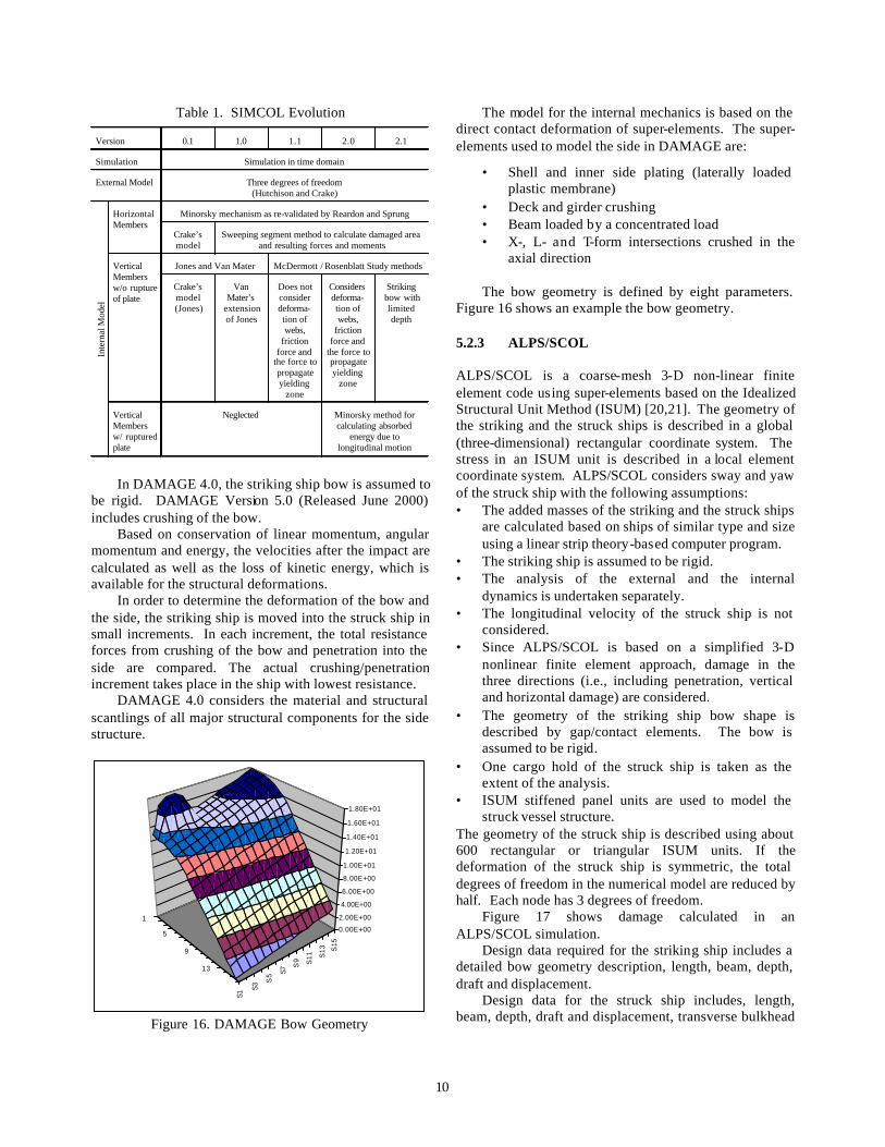
Table 6 lists the bow and struck ship model cases considered in the SIMCOL bow model development. Four rigid bow tests were run to validate SIMCOL calculations. These are labeled R-1 through R-4 in Table 6. Ten conventional FEA bow analyses were run to validate the simpler intersection bow model results. These are labeled C-1 through C-10 in Table 6. Two types of intersection model analyses were accomplished. Tests I-1 through I-4 use closed-form equations from Pedersen [34], Amdahl [35], and Yang and Caldwell [36]. Tests I-5 through I-16 use intersection elements applied in LSDYNA simulations.
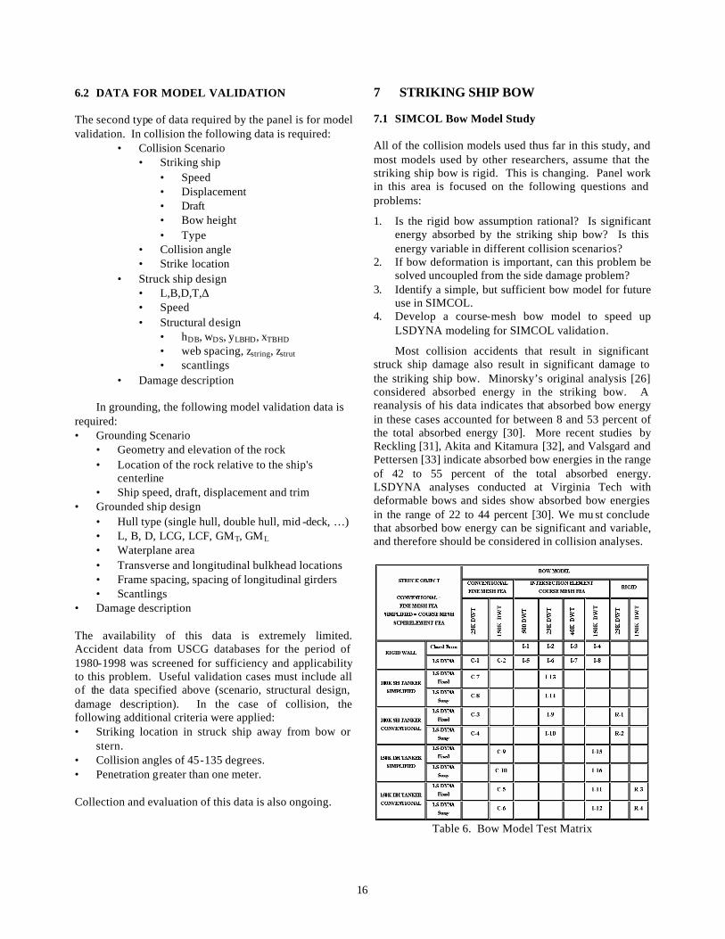
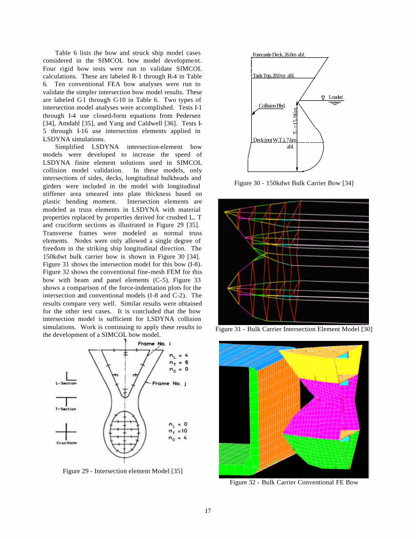
Simplified LSDYNA intersection-element bow models were developed to increase the speed of LSDYNA finite element solutions used in SIMCOL collision model validation. In these models, only intersections of sides, decks, longitudinal bulkheads and girders were included in the model with longitudinal stiffener area smeared into plate thickness based on plastic bending moment. Intersection elements are modeled as truss elements in LSDYNA with material properties replaced by properties derived for crushed L, T and cruciform sections as illustrated in Figure 29 [35]. Transverse frames were modeled as normal truss elements. Nodes were only allowed a single degree of freedom in the striking ship longitudinal direction. The 150kdwt bulk carrier bow is shown in Figure 30 [34]. Figure 31 shows the intersection model for this bow (I-8). Figure 32 shows the conventional fine-mesh FEM for this bow with beam and panel elements (C-5). Figure 33 shows a comparison of the force-indentation plots for the intersection and conventional models (I-8 and C-2). The results compare very well. Similar results were obtained for the other test cases. It is concluded that the bow intersection model is sufficient for LSDYNA collision simulations. Work is continuing to apply these results to the development of a SIMCOL bow model.
Figure 29 - Intersection element Model [35]
Loaded
Deck (not W.T.), 7.6m abl.
Tank Top, 20.0 m abl.
Collision Bhd.
Tl =
15.9
6m
Forecastle Deck, 26.0m abl.
Figure 30 - 150kdwt Bulk Carrier Bow [34]
Figure 31 - Bulk Carrier Intersection Element Model [30]
Figure 32 - Bulk Carrier Conventional FE Bow

18
0.00E+00
1.00E+08
2.00E+08
3.00E+08
4.00E+08
5.00E+08
6.00E+08
7.00E+08
8.00E+08
0 5 10 15 20 25 30
Penetration (m)
Forc
e (N
)
Intersection Model
Conventional Model
Figure 33 - 150kdwt Bulk Carrier Striking Rigid Wall
[30]
7.2 DAMAGE Bow Model DAMAGE 5.0 includes a deformable bow. The initial bow geometry is the same as in Damage 4.0, illustrated in Figure 16. Bow crushing is modeled using L-, T- and X-form super-elements in an ‘intersecting unit method’ [37]. Bow and side force-deformation calculations are completed separately (uncoupled). These calculations are performed assuming that the bow strikes a rigid wall and that the side is struck by a rigid bow. The results are then compared incrementally with deformation applied to the weakest component (bow or side) at each increment. This results in deformation and energy absorption in both components.
7.3 DTU Bow Model [38]
A’’ A’
δA δB
Deformation of the Striking Vessel
Striking Vessel
Struck Vessel
Figure 34 - Deformation of vessels during coll ision. The A’s relate to areas not lengths
A more recent DTU model also predicts damage to struck and striking vessels in a collision event [38]. The analysis is carried out in penetration steps. Only one of the involved vessels can be deformed in each step. By a
comparison of the crushing forces for respectively the bow and the side, it can be determined which vessel deforms during the considered step.
Before calculation of the deformation of the two vessels the following calculations are carried out: 1. The Force-Penetration curve Fstruck(δA) for the struck
vessel is calculated, where the striking vessel is rigid. 2. The Force-Penetration curve Fstriking(δB) for the
striking vessel is calculated, where the struck vessel is assumed rigid.
If the striking vessel has a bulbous bow, the analysis of the crushing forces is separated into a bulb analysis and an analysis of the top of bow above the bulb.
The force-deformation curve for the struck vessel is determined by the procedure described in Section 5.2.4 and for the striking vessel by the procedure described in Pedersen et. al [34].
A commonly used procedure for taking into account the deformation of the bow is to compare the two force-penetration curves, Fstruck(δA) and Fstriking(δB), at each step. This approach, however, only includes a very limited level of interaction. In reality, the force-penetration curve for the side of the struck vessel is a function of the deformation of the bow, and vice versa. This stronger interaction is taken into account by comparing the forces FA and FB, which is determined as:
Struck vessel: ( )'''
AA
FF AStruckA δ= (1)
Striking vessel: ( )BAStrikingB FF δδ += (2)
where FA force to crush the struck vessel; FB force to crush the striking vessel; Fstruck force from the force-penetration curve for struck
vessel, where the striking vessel is rigid; Fstriking force from the force-penetration curve for
striking vessel, where the struck vessel is rigid; δA penetration into the struck vessel; δB deformation of the striking vessel; A’ cross-sectional area of the striking vessel taken
at a distance of δA+δB from bow or bulb tip; A’’ cross-sectional area of the striking vessel taken
at a distance of δA from bow or bulb tip; See also Figure 34. The forces at the struck and the striking vessel FA and FB are compared • If FA > FB
Deformation of striking vessel, δB is increased • If FB > FA
Deformation of struck vessel, δA is increased The reason for correcting the resistance of the struck
vessel is that if the bow is deformed, the resistance is approximately equal to the force at the side times the ratio between the areas. For a single hull vessel the correction

19
will have nearly no influence, but for a double hull vessel, there will be some corrections when the bow penetrates the inner side. See Figure 34.
When the deformation patterns of the struck and the striking vessel are known, the total absorbed energy can be calculated and compared with the energy calculated by the external dynamics. See Pedersen and Zhang [29].
8 STRUCTURAL DESIGN FOR COLLISION AND GROUNDING
The function of a tank vessel’s structural system may be viewed from the standpoints of normal operation and casualty operation. In providing adequate resistance for normal operations, the objective in structural design is to maintain structural integrity of the hull girder, of bulkheads, decks, etc., and of plating, stiffeners and details. Other considerations relate to vessel size, complexity and heaviness of structure, producibility and maintainability. In terms of casualty operations, the objective is to maintain vessel integrity and to protect cargo, or conversely to protect the environment from oil pollution in case of a casualty. In this case the primary considerations should include: 1. Resistance to fire and explosion damage and its
containment, 2. Resistance to collision and grounding damage, 3. Containment of petroleum outflow if damage does
occur, and 4. Maintenance of sufficient residual strength after
damage in order to permit salvage and rescue operation and to minimize further damage and spilling of oil.
Figure 35 - Single-Hull Tanker [39]
Tank vessels have traditionally been designed as
single-skinned hulls, Figure 35 [39]. Depending on the size of the vessel, longitudinal bulkheads are often
present, and the overwhelming majority of single-skinned designs are longitudinally stiffened. OPA ’90 mandates the use of double-skinned tanker designs, Figure 36 [39].
Figure 36 - Double-Hull Tanker [39]
The Marine Board of the National Research Council
has recently convened a "Committee on Evaluating Alternative Tanker Designs". The committee is to establish, for the first time, a rational methodology to evaluate alternatives to the double hull. The US Coast Guard is sponsoring this Committee, and its report is expected in the first quarter of 2001.
The emphasis of new and proposed requirements for reducing the probability of oil cargo outflow has been on the subdivision of cargo spaces. The impact of hull structure on the reduction of outflow has had more limited attention. The complexity of determining the contribution of structure to cargo protection and the unpredictability of structural response under the variety of potential damage scenarios have no doubt contributed to this set of circumstances.
The following subsections address the subject of vessel structural design characteristics for collision, grounding and bow impact. The intent is to consider what has been learned from analytical studies regarding structural design features that may suggest future modifications and alternatives to enhance resistance to cargo outflow.
8.1 Collisions
8.1.1 Analytical Indications – Struck Ship
The sequence of structural events during a collision varies according to the nature of the collision and vessel design. Figures 37 and 38 [24] provide general flow diagrams representing the phenomena for single and double hull tankers. This information is useful in identifying where greater resistance can be addressed.

Figure 37 - Macro flow diagram for side collision plastic-energy analysis of a single hull [24]
Initially, the stiffened hull plating distorts in a plastic bending phase, with plastic “hinges’ forming in the vicinities of the strike and the web frames flanking the strike. During this phase, insignificant membrane tension develops. For a typical tanker with longitudinal angles stiffening the hull plating, the longitudinal angle -shaped
stiffeners then buckle in the vicinity of the flanking web frames, and possibly “trip” in the vicinity of the strike. Subsequently, the stiffened hull unloads momentarily as the strike continues, but reloads in a membrane-tension phase. The hull ruptures at the end of this phase, with possibly the flanking web frames yielding or buckling

21
before the hull ruptures. In such cases, the me mbrane-tension phase includes two sub-phases: (1) there is no transverse movement of the web frames flanking the strike; and (2) the web frames flanking the strike move inward toward the ship’s centerline, and the damage extends into the adjacent web frame spaces. During these phases, the deck is also distorting in membrane tension. However, the deck behavior is assumed not to affect the sequences of the options.
Other sequences of phenomena are possible. A hull with longitudinal stiffeners, such as rectangular bars that are not apt to buckle or trip, tend to rupture before significant membrane tension has a chance to develop.
Alternatively, with any type of hull stiffeners, very weak web frames can yield or buckle before rupture or buckling of the longitudinal stiffeners, in which case the damaged length increases during the bending phase. These phenomena are unlikely, however, for typical ships.
Figure 38 - Macro flow diagram for side collision plastic-energy analysis of a double hull [24]

Figure 39 - Energy Absorption of Structural Components
(Standard VLCC) [40]
Figure 40 - Energy Absorption Capacity [40]
The contribution of various structural components for
a ULCC with a more conventional double side structure is shown in Figure 39 [40]. 8.1.2 Application
With the knowledge acquired from understanding the process identified by the analytical evaluations, it is possible to postulate hull structural features that may
enhance resistance to collision. These fall into two categories: • Conventional hull structural arrangements that are
modified to enhance energy absorption. • Unconventional hull structural arrangements that
include structurally actuated mechanisms for energy absorption. As part of the research project for improved tanker
safety against collision and grounding, the Association for Structural Improvement of the Shipbuilding Industry (ASIS) of Japan conducted a study of varying structural characteristics of a conventional VLCC design and applying a more unconventional structural feature as well [40]. The more conventional alterations included use of high strength steel, additional shell stringers, a longitudinal strut in the outboard cargo tank supporting the double side, and a double side unidirectional stiffening system. As the side-shell has shown to be a significant contributor to energy absorption, an unconventional new skin composed of double plate panels internally stiffened by web frames, essentially a cored panel skin providing additional net shell thickness, was substituted for the conventional stiffened plate. The results are shown in Figure 40. Other ideas of the more conventional nature included: • Bulkhead stools on the wing tank side to reduce hard
spots and increase damage length. • Reduced stiffness of web frames to increase damage
length. • Increased side-shell plating thickness, especially
from the ballast waterline up, to increase membrane tension in the side-shell.
• Decreased spacing of side-shell longitudinals and added intermediate vertical web frames on the side shell to increase the integrity of the side-shell.
• Increased number of horizontal stringers in the wing tank to increase side skin integrity and provide additional material for membrane tension.
Although the practicability and acceptance from a regulatory point of view of very unconventional approaches may be seriously in doubt, it is nevertheless possible to postulate alternatives, and in fact the greatest step in the level of possible energy absorption is likely with an unconventional approaches:
• Controlled pressure fluid chamber in the wing tanks
wherein the venting of fluid under pressure to other spaces when compressed during collision results in energy dissipation.
• Introduction of material in wing ballast-tanks that does not reduce ballast capacity significantly, but increases energy absorption, like ultra-large open-cell

23
foam. Permeability and inspection are possible problems with this approach.
• Truss structure separating wing tank skins. Such an arrangement can enhance the integrity of the inner hull longer as the truss deforms while supporting the outer skin and more slowly loading the inner skin.
• Pre-planned failure or “crumple zones” as have been developed by the automobile industry for the more critical and predictable areas of damage.
• A foam release system actuated in the event of an impending collision within the expected area of contact to increase stiffness and energy absorption.
8.2 Bow Impact
8.2.1 Analytical Indications
The significance of the energy absorption in bow damage and the effects of the bow interacting with the struck ship’s side structure make it a critical element in considering collision results. Calculations assuming rigid bows with vertical stems and no bulbs have simplified analyses and fostered understanding, but do not depict the current and likely future nature of bows. Ship resistance, powering and seakeeping requirements are likely to continue to foster the existence of bows with raked stems and bulbs into the future.
Analytical evaluations do point a way to considering bows. If they are deformable, they will account for a sizeable portion of the total energy absorption in a collision. If they can be made to deform in a manner that does not cause premature failure of important struck ship energy absorbing structure, such as the side shell, then the same attributes of a rigid vertical stem bow will be achieved at the struck vessel.
8.3 Application
The bows of ships incorporate a significant amount of stiff horizontal fore and aft reinforcing structural elements that enhance the rigidity of the structure. Alternatively, arrangements with transverse stiffening coupled with appropriate spacing can lead to significant folding deformation, which can effectively reduce or eliminate the protrusions of the upper bow and bulb as well as their structural hard-spots. Recent studies [44] have confirmed that lower crushing pressure of a bulbous bow is preferable to avoid the early rupture of the struck sideshell and the crushing strength should not exceed that of the side structure.
8.4 Grounding
8.4.1 Analytical Indications – Grounding
The potential phases of grounding are depicted in Figure 41. In grounding and raking, the vessel has forward speed. In stranding it does not.
Model testing and computer finite element simulation of a stranding for a 280000 dwt tanker double bottom resulted in the lateral load versus indentation of up to 2m shown in Figure 42. The peak point, point 1, denotes the buckling of the center longitudinal girder, and point 2, the fracture of the outer bottom plating. Point 3 indicates fracture of the center girder-floor connection. It is interesting to note that the response shown in Figure 42 is similar to that predicted for collision, with the principal difference being the nature of the obtrusive loading, which may be a line load for a collision and a point load for a grounding.
Raking bottom damage is of significantly different character than the grounding damage heretofore discussed. In raking damage, the obstruction ruptures the bottom structure and then continues destructive shearing, tearing and buckling as the vessel continues to move in its direction of motion, Figure 43. The length of bottom raking is based on an energy balance concept where the kinetic energy of the vessel is entirely absorbed by the destruction of bottom structure.
Figure 41 - Model of the grounding process [41,42]
An energy analysis for grounding which takes into account energy due to the tearing that occurs during tracking-type collisions presumes that in such cases the damage will be long and shallow, involving plate tearing, but relatively little volume distortion of the inner structure. However, Figure 42 indicates that if there is a vertical component to the striking force, after fracture of the outer plating at point 2, there is an increase in stiffness leading up to point 3 and beyond as more girders and floors come into contact with the obstruction. Figure 44 also indicates a retention of stiffness.

24
Figure 42 - Load versus lateral indentation for 280000
dwt tanker double bottom [42]
Figure 43 - Bottom raking due to grounding
Figure 44 - Raking force versus penetration length by
experiments [41]
8.4.2 Application
In resisting both grounding and raking damage, it is clear that the bottom shell and the internal grid of the transverse floors, longitudinal girders and bulkheads is critical.
In the case of raking damage, the longitudinal stiffness of floors and their ability to absorb energy in distortion are more critical than their support of the shell. As in this case the distorting force is applied in the weakest direction of the floor, the situation is further complicated. Clearly, the more floors and the smaller the spans between their longitudinally resistive structure, the better. On the other hand, this arrangement will serve to limit the lateral deflection and therefore, the energy absorption in a stranding. Other ideas have included: • Increase the scantlings of the lower one-third part of
the hull. • Slope the inner bottom, higher at the collision
bulkhead and lowering to the regulatory requirement at the end of the first cargo tank.
• Preclude web frame and bulkhead damage propagation through the inner bottom by introducing a discontinuity in the rigidity between the two. A bulkhead stool would be an example.
9 CONCLUSIONS The almost two-year effort of the panel has achieved or partially achieved many of the original objectives stated in the introduction to this paper:
• Simplified grounding models have been investigated, compared and assessed. DAMAGE 4.0 is shown to be an excellent tool for comparative analysis of grounding damage, and based on limited validation, provides good results for cases with similar idealized rock geometry. More validation is required. Limitations include the ability to consider only conventional ship geometries and an idealized pinnacle geometry. Grounding on other rock geometries, reefs, etc., cannot be analyzed using DAMAGE, but should be considered in the future as an important part of a complete probabilistic analysis. Only a preliminary attempt at probabilistic analysis using DAMAGE was completed.
• Four simplified collision models have been investigated, compared and assessed. The models provide similar penetration results for the cases considered. Although some limited validation has been accomplished for specific mechanisms used in the models, more validation is required. The prediction of longitudinal extent of damage, particularly at transverse bulkheads, remains largely unexplored. This is very important for oil outflow and damage stability calculations. This prediction

25
requires consideration of various collision angles and struck ship speed. Consideration of striking bow deformation is a relatively new addition to the collision models. Further application and validation of bow models and their coupling to struck ship models is required. Most of the researchers are using finite element analysis as part of simplified model validation. Only a preliminary attempt at probabilistic analysis using SIMCOL was completed. Additional analysis is in progress.
• Data for model validation and scenario definition is very limited. A proposed data requirement is specified in this paper. The search for data to fill the requirement goes on with the support of the USCG, SSC and SNAME. Funding and significant IMO and class society support may ultimately be necessary to fully satisfy this data requirement.
• Some progress has been made in the definition of scenarios and conditions for grounding and collision analyses, but limited data is also hampering this effort. Data describing the worldwide population of ships that might be involved in collisions is available, but since specific struck ships trade in specific ports on specific routes, it is expected that they will encounter a related subset or distribution of other ships (striking ships). Sufficient data has not been obtained to quantify or assess this hypothesis. More data is also required for collision angle, strike location, grounding and collision ship speeds and grounding bottom description.
• A number of possibilities for design improvement are presented in the paper. As tools, standard scenarios, methodologies and performance criteria are evaluated and defined they must be used to assess innovative designs, and to optimize and evaluate conventional designs. Damage models should be applied in a total ship design framework to trade-off variations in structural design, subdivision and system redundancy.
• The application of this work in a regulatory framework requires that a very simplified, preferably parametric relationship be established between structural design variables and probabilistic damage. This work remains to be done.
10 SIGNIFICANCE This work is not done. Grounding and collision models have been improved, data requirements have been defined, and design possibilities for improved crashworthiness have been identified, but this work must be finished and validated before regulations and designs can be improved. This is our ultimate goal. Based on the progress thus far, the following important areas of work
can proceed in parallel with the remaining model development and validation: • Probabilistic analysis • Sensitivity analysis and the development of
parametric equations relating damage extent to structural design variables in conventional designs
• Modification of the grounding and collision models to consider unconventional designs
11 CONTINUING WORK OF THE PANEL Individual sections of this paper have discussed possibilities for future work. This panel has been very active and very productive, but in many ways has just scratched the surface. Individual papers will be written in most all areas covered by this summary paper. Subsequent work will include: completion of sufficient grounding and collision models, validation of the models, specification and acceptance of standard accident scenarios, and ultimately application of models and scenarios to improved structural design in collision and grounding. A two-year continuation of the panel will be proposed to the T&R Committee. This continuation will include a new charter with new objectives and deliverables. The Ad Hoc framework has proven very effective for meaningful collaboration and effort. The panel chairman thanks all those who have contributed.
12 REFERENCES [1] IMCO, Regulations on Subdivision and Stability of
Passenger Ships as Equivalent to Part B of Chapter II of the International Convention for the Safety Of Life At Sea, IMCO Resolution A.265 (VIII), adopted on 20 Nov 1973.
[2] Gilbert, R. and Card, J.C., "The New International Standard for Subdivision and Damage Stability of Dry Cargo Ships", Marine Technology, Vol. 27, No. 2, March 1990, pp. 117-127.
[3] “Interim Guidelines for Approval of Alternative Methods of Design and Construction of Oil Tankers under Regulation 13F(5) of Annex I of MARPOL 73/78”, Resolution MEPC.66 (37), Adopted September 14, 1995.
[4] “IMO Comparative Study on Oil Tanker Design,” IMO paper MEPC 32/7/15, Annex 5, Distribution of Actual Penetrations and Damage Locations Along Ship’s Length for Collisions and Groundings.
[5] Sirkar, J., et al., “A Framework for Assessing the Environmental Performance of Tankers in Accidental Groundings and Collisions”, 1997 SNAME Annual Meeting, October 1997.
[6] Rawson, C., Crake, K. and Brown, A.J., “Assessing the Environmental Performance of Tankers in

26
Accidental Grounding and Collision”, 1998 SNAME Annual Meeting, November 1998.
[7] Brown, A. and Amrozowicz, M., “Tanker Environmental Risk - Putting the Pieces Together”, SNAME/SNAJ International Conference on Designs and Methodologies for Collision and Grounding Protection of Ships, August 1996.
[8] Card, J. C., “Effectiveness of Double Bottoms in Preventing Oil Outflow from Tanker Double Bottoms”, Marine Technology, January 1975.
[9] ISSC, Report by Specialist Panel V.4 – Structural Design Against Collision and Grounding, Proceedings of the 13th International Ship and Offshore Structures Congress 1997, Trondheim, Norway, 1997.
[10] W. Abramowicz and M. Sinmao, “User’s Manual and Modeling Guide for the Program DAMAGE, Joint MIT-Industry Program on Tanker Safety, Report No. 66, June 1999.
[11] B. Cerup Simonsen and T. Wierzbicki. “Grounding Bottom Damage and Ship Motion over a Rock”. Int. J. of Offshore and Polar Engineering, Vol. 6, no. 3, Sep. 1996.
[12] B. Cerup Simonsen, “Mechanics of Ship Grounding”, PhD thesis, Department of Naval Architecture and Offshore Engineering, the Technical University of Denmark, February 1997.
[13] B. Cerup Simonsen, “Ship Grounding on Rock: I Theory”, Marine Structures, Vol. 10, pp. 519-562, 1997
[14] B. Cerup Simonsen, “Ship Grounding on Rock: II Validation and Application”, Marine Structures, Vol. 10, pp. 563-584, 1997.
[15] Wang, G., Ohtsubo, H., and Liu D., “Simple Method of Predicting the Grounding Strength of Ships”, Journal of Ship Research, Vol. 41, No. 3, Sept. 1997.
[16] B. Cerup Simonsen. “DAMAGE Theory Validation”, Joint MIT-Industry Program on Tanker Safety, Report no 63, May 1998.
[17] Tikka, K.K., and Chen Y.J., “Prediction of Structural Response in Grounding – Application to Structural Design”, SSC/SNAME Ship Structural Symposium June 13-14, 2000.
[18] Giannotti, J.G., Johns, N., Genalis, P. and Van Mater, P.R., “Critical Evaluations of Low-Energy ship Collision Vol. I - Damage theories and Design Methodologies”, Ship Structure Committee Report No. SSC-284, 1979
[19] Simonsen, B.C., “Theory and Validation for the DAMAGE Collision Module”, Joint MIT-Industry Program on Tanker Safety, Report No. 67, June 1999.
[20] Paik, J.K., et al, "On Rational Design of Double Hull Tanker Structures against Collision”, 1999 SNAME Annual Meeting, 1999.
[21] Paik, J.K. and Pedersen, P.T., "Modeling of the Internal Mechanics in Ship Collisions", Ocean Engineering, Vol. 23, No. 2, pp. 107-142, 1996.
[22] Chen, D., “Simplified Collision Model (SIMCOL)”, Dept. of Ocean Engineering, Virginia Tech, Master of Science Thesis, May 2000.
[23] Hutchison, B.L., “Barge Collisions, Rammings and Groundings - an Engineering Assessment of the Potential for Damage to Radioactive Material Transport Casks”, Report No. SAND85-7165 TTC-05212, 1986.
[24] Rosenblatt & Son, Inc, “Tanker Structural Analysis for Minor Collision”, USCG Report, CG-D-72-76, 1975.
[25] McDermott, J.F., et al, “Tanker Structural Analysis for Minor Collisions”, SNAME Transactions, Vol. 82, pp. 382-414, 1974.
[26] Minorsky, V. V. (1959) “An Analysis of Ship Collisions with Reference to Proteciton of Nuclear Power Plants,” Journal of Ship Research.
[27] Reardon, P. and Sprung, J.L., “Validation of Minorsky’s Ship Collision Model and Use of the Model to Estimate the Probability of Damaging a Radioactive Material Transportation Cask During a Ship Collision”, Proceedings of the International Conference on Design and Methodologies for Collision and Grounding Protection of Ships, San Francisco, August 1996.
[28] Crake, K., “Probabilistic Evaluations of Tanker Ship Damage in Grounding Events”, Naval Engineer Thesis, MIT, 1995.
[29] Pedersen P.T. and Zhang S. “On Impact Mechanics in Ship Collisions”, Marine Structures, Vol. 11, pp. 429-449, 1998.
[30] Vakkalanka, Suryanarayana, “Simplified Bow Model for a Striking Ship in Collision”, Dept. of Ocean Engineering, Virginia Tech, Master of Science Thesis, July 2000.
[31] Reckling, K.A. (1983), "Mechanics of Minor Ship Collisions", International Journal of Impact Engineering, Vol. 1, No. 3, pp. 281-299.
[32] Akita, M. and Kitamura, K. (1972), “A Study on Collision by an Elastic Stem to the Side Structure of Ships”, Trans. SNAJ, 131, 307-317.
[33] Valsgard, S. and Pettersen, E. (1982), "Simplified Non-Linear Analysis of Ship/Ship Collisions", Norwegian Maritime Research, No. 3, pp. 2-17.
[34] Pedersen, P.T., et al, "Ship Impacts: Bow Collisions", International Journal of Impact Engineering, Vol. 13, No. 2, pp. 163-187, 1993.
[35] Amdahl, J., “Energy Absorption in Ship-Platform Impacts”, Dr. Ing. Thesis, Report No. UR-83-84, The Norwegian Institute of Technology, Trondheim, 1983.
[36] Yang, P. D. C., and Caldwell, J. B., “Collision Energy Absorption of Ships’ Bow Structures,” International Journal of Impact Engineering, Vol. 7, No. 2, pp. 181-196, 1988.
[37] Abramowicz, W., “Crush Resistance of “T”, “Y”, “X” Sections,” Joint MIT-Industry Program on Tanker Safety, Report #24, 1994.

27
[38] Lützen M., Simonsen B.C, Pedersen P.T., “Rapid Prediction of Da mage to Struck and Striking Vessels in a Collision Event”, Proceedings of Ship Structures for the New Millennium: Supporting Quality in Shipbuilding, Arlington, June 13-14 2000.
[39] Daidola, J.C., “Tanker Structure Behavior During Collision and Grounding,” SNAME Marine Technology, January 1995.
[40] Kitamuru, O., "Comparative Study on Collision Resistance of Side Structure," SNAME Marine Technology, October, 1997.
[41] Kuroiwa., T., Kawamoto, Y., and Yuhara, T., “Study on Damage Ship Bottom Structure Due to Grounding,” Conference on Marine Safety and Environment—Ship Production, The Netherlands, June 1992.
[42] Amdahl, J. and Kavlie, D., “Experimental and Numerical Simulation of Double Hull Stranding,” DNV-MIT, Det norske Veritas, Oslo, Sept.1992.
[43] Okamoto, T. et al, “Strength Evaluation of Naval Unidirectional-Girder-System Product Oil Carrier by Reliability Analysis,” Trans. SNAME, Vol. 93, 1985.
[44] Kitamuru, O., “Buffer Bow Design for the Improved Safety of Ships,” Ship Structure Symposium, June, 2000.