Brother MFC 6510dw Sm
393
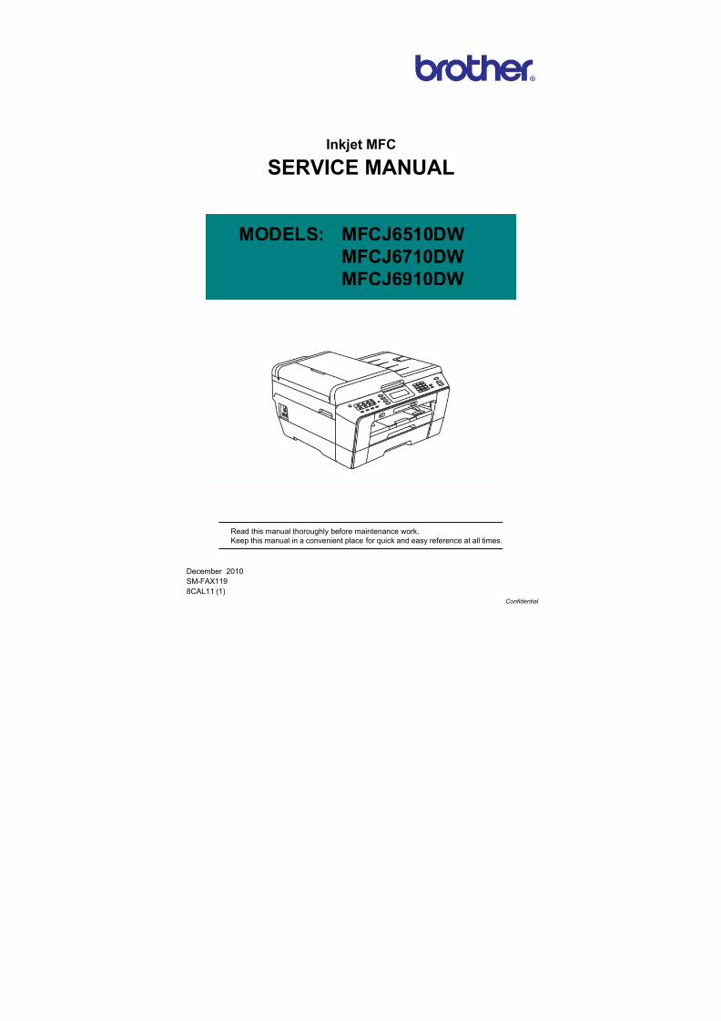
Confidential Inkjet MFC SERVICE MANUAL MODELS: MFCJ6510DW MFCJ6710DW MFCJ6910DW December 2010 SM-FAX119 8CAL11 (1) Read this manual thoroughly before maintenance work. Keep this manual in a convenient place for quick and easy reference at all times.
-
Upload
klema-hanis -
Category
Documents
-
view
236 -
download
0
Transcript of Brother MFC 6510dw Sm
8/15/2019 Brother MFC 6510dw Sm
http://slidepdf.com/reader/full/brother-mfc-6510dw-sm 1/392
Confidential
Inkjet MFC
SERVICE MANUAL
MODELS: MFCJ6510DWMFCJ6710DW
MFCJ6910DW
December 2010SM-FAX119
8CAL11 (1)
Read this manual thoroughly before maintenance work.
Keep this manual in a convenient place for quick and easy reference at all times.
8/15/2019 Brother MFC 6510dw Sm
http://slidepdf.com/reader/full/brother-mfc-6510dw-sm 2/392
Confidential
© Copyright Brother 2010
All rights reserved.
No part of this publication may be reproduced in any form or by any means without permission in writing
from the publisher.
Specifications are subject to change without notice.
Trademarks
The Brother logo is a registered trademark of Brother Industries, Ltd.
Brother is a registered trademark of Brother Industries, Ltd.
Multi-Function Link is a registered trademark of Brother International Corporation.
Windows Vista is either a registered trademark or trademark of Microsoft Corporation in the United
States and/or other countries.
Microsoft, Windows, Windows Server and Internet Explorer are registered trademarks of Microsoft
Corporation in the United States and/or other countries. Apple and Macintosh are trademarks of Apple Inc., registered in the United States and other countries.
Adobe, Flash, Illustrator, PageMaker and Photoshop are either registered trademarks or trademarks of
Adobe Systems Incorporated in the United States and/or other countries.
Nuance, the Nuance logo, PaperPort and ScanSoft are trademarks or registered trademarks of Nuance
Communications, Inc. or its affiliates in the United States and/or other countries.
PowerPC is a trademark of International Business Machines Corporation.
Memory Stick, Memory Stick PRO, Memory Stick PRO Duo, Memory Stick Duo, MagicGate Memory
Stick, Memory Stick Micro and M2 are trademarks of Sony Corporation.
AOSS is a trademark of Buffalo Inc.
Wi-Fi, WPA, WPA2, Wi-Fi Protected Access and Wi-Fi Protected Setup are either trademarks orregistered trademarks of Wi-Fi Alliance in the United States and/or other countries.
Intel and Pentium are trademarks of Intel Corporation in the U.S. and other countries.
AMD is a trademark of Advanced Micro Devices, Inc.
FaceFilter Studio is a trademark of Reallusion, Inc.
BRAdmin Professional is a trademark of Brother Industries, Ltd.
UNIX is a registered trademark of The Open Group.
Linux is the registered trademark of Linus Torvalds in the U.S. and other countries.
CorelDraw, Corel Paint Shop Pro and Corel WordPerfect are trademarks or registered trademarks of
Corel Corporation and/or its subsidiaries in Canada, the United States and/or other countries.
Each company whose software title is mentioned in this manual has a Software License Agreement
specific to its proprietary programs.
Any trade names and product names of companies appearing on Brother products, related
documents and any other materials are all trademarks or registered trademarks of those
respective companies.

8/15/2019 Brother MFC 6510dw Sm
http://slidepdf.com/reader/full/brother-mfc-6510dw-sm 3/392
Confidential
The table below shows the functional comparison between the models covered by this manual.
Model MFCJ6510DW MFCJ6710DW MFCJ6910DW
Touch panel − − √
Lower tray (Paper tray #2) − √ √
Duplex scan − − Up to LTR/LGL/A4
8/15/2019 Brother MFC 6510dw Sm
http://slidepdf.com/reader/full/brother-mfc-6510dw-sm 4/392
i Confidential
TABLE OF CONTENTS
REGULATION....................................................................................................................... viii
SAFETY INFORMATION........................................................................................................ xi
CHAPTER 1 SPECIFICATIONS......................................................................................... 1-1
1.1 GENERAL ....................................................................................................................1-1
1.1.1 General ............................................................................................................1-1
1.1.2 Media Specifications........................................................................................1-1
1.1.3 Paper Handling ................................................................................................ 1-2
1.1.4 LCD/LED/Panel................................................................................................1-2
1.1.5 Memory............................................................................................................1-2
1.1.6 Interface ...........................................................................................................1-31.1.7 Others ..............................................................................................................1-3
1.2 TELEPHONE................................................................................................................ 1-4
1.3 FAX...............................................................................................................................1-4
1.4 PRINTER ......................................................................................................................1-4
1.5 COPY............................................................................................................................ 1-5
1.6 SCANNER ....................................................................................................................1-5
1.7 SOFTWARE ................................................................................................................. 1-5
1.8 NETWORK ...................................................................................................................1-6
1.8.1 Network............................................................................................................ 1-6
1.8.2 Wired................................................................................................................ 1-6
1.8.3 Wireless ...........................................................................................................1-6
1.9 SUPPLIES/OPTIONS ................................................................................................... 1-7
1.10 SERVICE INFORMATION............................................................................................1-7
1.11 PAPER.......................................................................................................................... 1-8
1.11.1 Paper Specifications ........................................................................................1-8
1.11.2 Printable Area ................................................................................................ 1-11
CHAPTER 2 ERROR INDICATION AND TROUBLESHOOTING......................................2-1
2.1 INTRODUCTION .......................................................................................................... 2-1
2.1.1 Precautions ......................................................................................................2-1
2.1.2 Initial Check .....................................................................................................2-2
8/15/2019 Brother MFC 6510dw Sm
http://slidepdf.com/reader/full/brother-mfc-6510dw-sm 5/392
ii Confidential
2.2 OVERVIEW...................................................................................................................2-3
2.2.1 Cross-section Drawings and Components.......................................................2-3
2.2.2 Paper Path for Documents and Recording Paper............................................2-4
2.2.3 Parts Names and Functions.............................................................................2-5
2.2.4 Block Diagram.................................................................................................. 2-7
2.2.5 Components..................................................................................................... 2-8
2.3 ERROR INDICATION................................................................................................... 2-9
2.3.1 Error Codes......................................................................................................2-9
2.3.2 Error Messages.............................................................................................. 2-13
2.3.3 Communications Error Codes........................................................................ 2-16
2.3.4 Status Monitor Errors .....................................................................................2-20
2.4 TROUBLESHOOTING ............................................................................................... 2-22
2.4.1 Error Cause and Solutions............................................................................. 2-22
2.4.2 Paper Feeding Problems ...............................................................................2-61
2.4.2.1 No paper feeding....................................................................................2-61
2.4.2.2 Double feeding ....................................................................................... 2-62
2.4.2.3 Recording paper jam .............................................................................. 2-63
2.4.2.4 Stains on recording paper ...................................................................... 2-67
2.4.3 Print-image Problems .................................................................................... 2-68
2.4.3.1 Defective images....................................................................................2-68
2.4.3.2 Troubleshooting from image defect........................................................ 2-69
2.4.4 Software-related Problems ............................................................................ 2-80
2.4.4.1 Cannot print data....................................................................................2-80
2.4.5 Network Problems..........................................................................................2-81
2.4.5.1 Cannot make a print through network connection .................................. 2-81
2.4.6 Document Feeding Problems ........................................................................ 2-82
2.4.6.1 Cannot feed documents ......................................................................... 2-82
2.4.6.2 Document double feeding.......................................................................2-82
2.4.6.3 Document jam ........................................................................................ 2-83
2.4.6.4 Wrinkles on documents .......................................................................... 2-84
2.4.6.5 Cannot detect the document size correctly ............................................ 2-84
2.4.7 Scanned-image Problems.............................................................................. 2-85
2.4.7.1 Defective images....................................................................................2-85
2.4.7.2 Troubleshooting from image defect........................................................ 2-85
2.4.8 Control Panel Problems................................................................................. 2-89
2.4.8.1 LCD shows nothing ................................................................................ 2-89
8/15/2019 Brother MFC 6510dw Sm
http://slidepdf.com/reader/full/brother-mfc-6510dw-sm 6/392
iii Confidential
2.4.8.2 Control panel inoperative........................................................................2-89
2.4.8.3 Lamps on the control panel does not light.............................................. 2-90
2.4.8.4 Touch panel inoperative (For models with touch panel)......................... 2-90
2.4.9 Fax Problems.................................................................................................2-91
2.4.9.1 No faxes can be sent.............................................................................. 2-91
2.4.9.2 Speed dialing or one-touch dialing will not work..................................... 2-91
2.4.9.3 No faxes can be received ....................................................................... 2-92
2.4.9.4 The ringer does not sound...................................................................... 2-92
2.4.9.5 In on-hook dialing, the speaker does not sound..................................... 2-92
2.4.9.6 Dial does not switch between tone and pulse ........................................ 2-93
2.4.9.7 A communications error occurs .............................................................. 2-93
2.4.9.8 Receive mode cannot be changed......................................................... 2-93
2.4.9.9 Caller ID not displayed ........................................................................... 2-93
2.4.10 Other Problems.............................................................................................. 2-94
2.4.10.1 The machine cannot be powered on or nothing appears on the LCD .... 2-94
2.4.10.2 When the power is on, the scanner crackles..........................................2-94
2.4.10.3 Memory card/PictBridge does not function.............................................2-94
2.4.10.4 Memory errors ........................................................................................ 2-95
2.4.10.5 Paper tray set does not work.................................................................. 2-95
CHAPTER 3 DISASSEMBLY AND ASSEMBLY ...............................................................3-1
3.1 SAFETY PRECAUTIONS AND HANDLING NOTES ..................................................3-1
3.2 PACKING .....................................................................................................................3-3
3.3 SCREW CATALOGUE................................................................................................. 3-4
3.4 SCREW TORQUE LIST ...............................................................................................3-5
3.5 LUBRICATION .............................................................................................................3-6
3.6 OVERVIEW OF GEARS.............................................................................................3-13
3.7 HARNESS ROUTING.................................................................................................3-14
3.8 DISASSEMBLY FLOW .............................................................................................. 3-31
3.9 DISASSEMBLY PROCEDURE.................................................................................. 3-33
3.9.1 Preparation ....................................................................................................3-33
3.9.2 Head/Carriage Unit ........................................................................................ 3-37
3.9.3 Scanner Cover (Scanner Unit) and Scanner Cover Support ......................... 3-50
3.9.4 Manual Feed Slot Cover and ADF & Document Cover ASSY....................... 3-55
3.9.5 Disassembly of ADF & Document Cover ASSY ............................................ 3-58
8/15/2019 Brother MFC 6510dw Sm
http://slidepdf.com/reader/full/brother-mfc-6510dw-sm 7/392
iv Confidential
3.9.6 Control Panel ASSY....................................................................................... 3-82
3.9.7 Disassembly of Control Panel ASSY ............................................................. 3-83
3.9.8 Backup Battery, Speaker and Upper Cover................................................... 3-88
3.9.9 Ink Cartridge Cover, Front Cover, Wireless LAN PCB and Media Module
Cover ............................................................................................................. 3-923.9.10 Main PCB....................................................................................................... 3-94
3.9.11 LT Cover*, T2 Paper Pull-in Roller ASSY, and Jam Clear Cover ..................3-99
3.9.12 MJ/PS Shield Unit (MJ PCB and Power Supply PCB).................................3-101
3.9.13 CR Encoder Strip and its Guard Film...........................................................3-106
3.9.14 Carriage PCB ASSY, Ink Refill ASSY and Ink Cartridge Detection
Sensor PCB ................................................................................................. 3-108
3.9.15 Ink Absorber Box, Ink Absorber Felt, and PF Encoder Disk ........................ 3-114
3.9.16 Duplex-printing Related Components ..........................................................3-116
3.9.17 Engine Unit, Flashing Box and Ink Cartridge Cover Switch.........................3-118
3.9.18 Components on the Engine Unit
(Earth spring, Maintenance unit, Carriage motor, CR support chassis,
Star wheel holder, Intermediate roller, Inner paper guide, Switchback
paper sensor PCB ASSY, Platen, DX chute roller holder ASSYs,
Inner chute ASSY, Registration sensor PCB ASSY and actuator,
PF encoder/PF sensor harness unit and actuator, PF encoder disk,
Paper feed motor, T1 paper pull-in roller ASSY) .........................................3-122
3.9.19 Paper Tray #1 ..............................................................................................3-135
3.9.20 Paper Tray #2 ..............................................................................................3-136
CHAPTER 4 ADJUSTMENTS AND UPDATING OF SETTINGS, REQUIRED AFTER
PARTS REPLACEMENT............................................................................... 4-1
4.1 IF YOU REPLACE THE HEAD/CARRIAGE UNIT OR ENGINE UNIT ........................4-1
[ 1 ] Update the head property data stored in the EEPROM on the main PCB* ........ 4-2
[ 2 ] Clean the new head/carriage unit (Function code 76)........................................4-5
[ 3 ] Print out a nozzle test pattern (Function code 09) ..............................................4-6
[ 4 ] Adjust the inclination of the head/carriage unit...................................................4-7
[ 5 ] Update the paper feeding correction value (Function code 58)........................ 4-10
[ 6 ] Adjust the height of the platen .......................................................................... 4-17
[ 7 ] Align vertical print lines in monochrome (Function code 65) ............................4-19
[ 8 ] Adjust margins in borderless printing (Function code 66).................................4-21
[ 9 ] Create head calibration data and write it into flash ROM
(Function code 02)............................................................................................ 4-24
[ 10 ] Check duplex printing ....................................................................................... 4-27
[ 11 ] Print out a total quality check pattern................................................................ 4-30
[ 12 ] Switch back to standby .....................................................................................4-32
8/15/2019 Brother MFC 6510dw Sm
http://slidepdf.com/reader/full/brother-mfc-6510dw-sm 8/392
v Confidential
[ 13 ] Replace the ink cartridges with the protective part ........................................... 4-32
[ 14 ] Obtain machine information at the user site (Instruction to the end user) ........ 4-32
4.2 IF YOU REPLACE THE MAIN PCB........................................................................... 4-33
[ 1 ] Load update programs/data.............................................................................. 4-34
[ 2 ] Customize the EEPROM on the main PCB (Function code 74) ....................... 4-37
[ 3 ] Initialize the EEPROM on the main PCB (Function code 01) ........................... 4-37
[ 4 ] Load local programs ......................................................................................... 4-37
[ 5 ] Restore machine information (Function code 46)............................................. 4-37
[ 6 ] Restore head calibration data (Function code 68)............................................ 4-37
[ 7 ] Check the sensor operation (Function code 32)............................................... 4-37
[ 8 ] Acquire white level data and set CIS scanner area (Function code 55) ........... 4-38
[ 9 ] Set an ID code (change the serial number) and update the head property
data................................................................................................................... 4-38
[ 10 ] Update the paper feeding correction value (Function code 58)........................4-40
[ 11 ] Align vertical print lines (Function code 65) ......................................................4-40
[ 12 ] Adjust margins in borderless printing (Function code 66).................................4-40
[ 13 ] Create head calibration data and write it into flash ROM (Function code 02) .. 4-40
[ 14 ] Print out an ADF copy chart and make a copy of that chart in ADF scanning.. 4-40
[ 15 ] Print out a total quality check pattern................................................................ 4-40
[ 16 ] Adjust the touch panel (Function code 78) (For models with touch panel)....... 4-40
[ 17 ] Switch back to standby .....................................................................................4-40
4.3 IF YOU REPLACE THE ADF OR ADF-RELATED PARTS ....................................... 4-41
[ 1 ] Print out an ADF copy chart and make a copy of that chart in ADF scanning.. 4-41
4.4 IF YOU REPLACE THE INK ABSORBER BOX OR FLUSHING BOX ..................... 4-44
[ 1 ] Reset each of the purge and flushing counters ................................................ 4-44
4.5 IF YOU REPLACE THE CONTROL PANEL ASSY, CONTROL PANEL PCB OR
LCD UNIT ................................................................................................................... 4-44
[ 1 ] Adjust the touch panel (Function code 78) (For models with touch panel)....... 4-44
[ 2 ] Check LCD operation (Function code 12) ........................................................ 4-44
[ 3 ] Check the operation of the control panel PCB (Function code 13)................... 4-44
4.6 IF YOU REPLACE THE FB UNIT* OR SCANNER COVER (SCANNER UNIT) .......4-45
[ 1 ] Acquire white level data and set CIS scanner area (Function code 55) ........... 4-45
[ 2 ] Print out an ADF copy chart and make a copy of that chart in ADF scanning
(For models with ADF)...................................................................................... 4-45
8/15/2019 Brother MFC 6510dw Sm
http://slidepdf.com/reader/full/brother-mfc-6510dw-sm 9/392
vi Confidential
CHAPTER 5 SERVICE FUNCTIONS .................................................................................5-1
5.1 MAINTENANCE MODE................................................................................................5-1
5.1.1 How to Enter the End User-accessible Maintenance Mode.............................5-1
5.1.2 How to Enter the Maintenance Mode Exclusive to Service Personnel ............5-2
5.1.3 List of Maintenance-mode Functions...............................................................5-4
5.1.4 Detailed Description of Maintenance-mode Functions ....................................5-5
5.1.4.1 EEPROM Parameter Initialization (Function code 01, 91) ....................... 5-5
5.1.4.2 Creating of Head Calibration Data and Writing it into Flash ROM
(Function code 02).................................................................................... 5-6
5.1.4.3 Printout of Scanning Compensation Data (Function code 05) .................5-9
5.1.4.4 ADF Performance Test (Function code 08)............................................ 5-11
5.1.4.5 Printout of Nozzle Test Pattern (Function code 09)................................ 5-12
5.1.4.6 Firmware Switch Setting and Printout (Function codes 10 and 11)
(User-accessible).................................................................................... 5-14
5.1.4.7 Operational Check of LCD (Function code 12) (User-accessible).......... 5-17
5.1.4.8 Operational Check of Control Panel PCB (Function code 13)................ 5-18
5.1.4.9 Updating of Firmware Using an External Memory (Function code 28)...5-19
5.1.4.10 Sensor Operational Check (Function code 32) ...................................... 5-20
5.1.4.11 Backup of Machine Information (Function code 46) (User-accessible).. 5-22
5.1.4.12 Setting of Country/Language (Function code 52) (User-accessible)......5-24
5.1.4.13 Transfer of Received FAX Data and/or Equipment's Log(Function code 53) (User-accessible)..................................................... 5-25
5.1.4.14 Fine Adjustment of Scanning Position (Function code 54)..................... 5-27
5.1.4.15 Acquisition of White Level Data and CIS Scanner Area Setting
(Function code 55).................................................................................. 5-28
5.1.4.16 Updating of Paper Feeding Correction Value (Function code 58)..........5-29
5.1.4.17 Checking of CIS Travel (Function code 59)............................................5-36
5.1.4.18 Printout of PRN/JPEG Files in Memory Card (Function code 61).......... 5-37
5.1.4.19 Travel Check of the Head/Carriage Unit and Initial Setup Mode(Function code 63).................................................................................. 5-39
5.1.4.20 Alignment of Vertical Print Lines in Monochrome (Function code 65).... 5-40
5.1.4.21 Margin Adjustment in Borderless Printing (Function code 66)
(User-accessible).................................................................................... 5-42
5.1.4.22 Updating of Head Property Data and Backup/Restoration of
Head Calibration Data (Function code 68) ............................................. 5-45
5.1.4.23 Traveling Speed Check of Head/Carriage Unit (Function code 69) ....... 5-47
5.1.4.24 Cleaning of Leveler Roller (LR) ASSY (Function code 70)..................... 5-48
5.1.4.25 EEPROM Customizing (Function code 74) ............................................ 5-49
8/15/2019 Brother MFC 6510dw Sm
http://slidepdf.com/reader/full/brother-mfc-6510dw-sm 10/392
vii Confidential
5.1.4.26 Travel of Head/Carriage Unit (for removing paper particles and
dust accumulated on the maintenance unit) (Function code 75)
(User-accessible).................................................................................... 5-52
5.1.4.27 Purge Operation (Function code 76) (User-accessible) .........................5-53
5.1.4.28 Print of the Equipment’s Log (Function code 77) ...................................5-56
5.1.4.29 Adjustment of Touch Panel (Function code 78) ..................................... 5-59
5.1.4.30 Display of the Equipment's Log (Function code 80) (User-accessible)..5-61
5.1.4.31 Equipment Error Code Indication (Function code 82)
(User-accessible).................................................................................... 5-66
5.1.4.32 Output of Transmission Log to the Telephone Line (Function code 87)
(User-accessible).................................................................................... 5-66
5.1.4.33 Assurance Mode Switch Setting (Function code 88) (User-accessible). 5-67
5.2 OTHER SERVICE FUNCTIONS................................................................................. 5-74
5.2.1 Cancellation of the Pin TX Lock Mode (Not applicable to Japanese and
U.S.A. models) ............................................................................................... 5-74
5.2.2 Displaying the Firmware Version ................................................................... 5-74
5.2.3 Travel of Head/Carriage Unit ......................................................................... 5-74
CHAPTER 6 Circuit Diagrams and Wiring Diagrams ..................................................... 6-1
APPENDIX 1 SERIAL NUMBERING SYSTEM..........................................................App. 1-1
APPENDIX 2 DELETION OF USER SETTING INFORMATION................................App. 2-1
A2.1 Deleting User Setting Info from the Machine ........................................App. 2-1
APPENDIX 3 INSTALLING THE MAINTENANCE PRINTER DRIVER .....................App. 3-1
8/15/2019 Brother MFC 6510dw Sm
http://slidepdf.com/reader/full/brother-mfc-6510dw-sm 11/392
viii Confidential
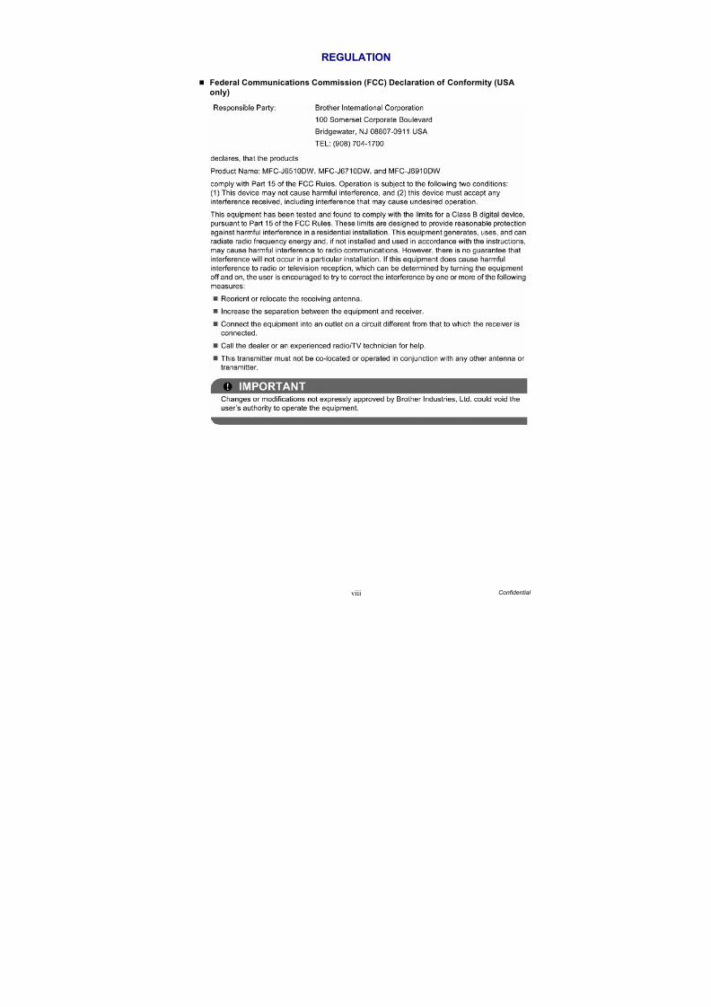
REGULATION
Federal Communications Commission (FCC) Declaration of Conformity (USA
only)
8/15/2019 Brother MFC 6510dw Sm
http://slidepdf.com/reader/full/brother-mfc-6510dw-sm 12/392
ix Confidential
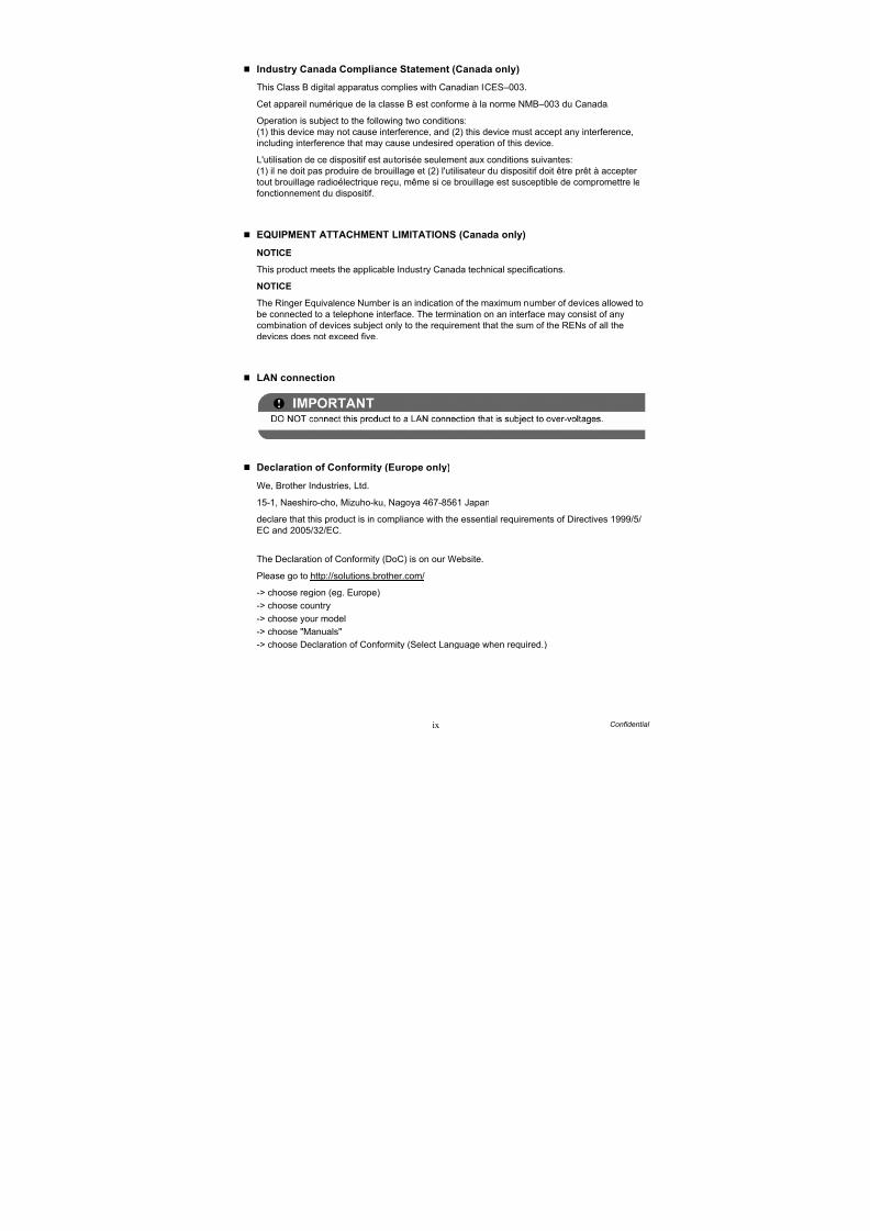
Industry Canada Compliance Statement (Canada only)
This Class B digital apparatus complies with Canadian ICES–003.
Cet appareil numérique de la classe B est conforme à la norme NMB–003 du Canada.
Operation is subject to the following two conditions:
(1) this device may not cause interference, and (2) this device must accept any interference,
including interference that may cause undesired operation of this device.
L'utilisation de ce dispositif est autorisée seulement aux conditions suivantes:
(1) il ne doit pas produire de brouillage et (2) l'utilisateur du dispositif doit être prêt à accepter
tout brouillage radioélectrique reçu, même si ce brouillage est susceptible de compromettre le
fonctionnement du dispositif.
EQUIPMENT ATTACHMENT LIMITATIONS (Canada only)
NOTICE
This product meets the applicable Industry Canada technical specifications.
NOTICE
The Ringer Equivalence Number is an indication of the maximum number of devices allowed to
be connected to a telephone interface. The termination on an interface may consist of any
combination of devices subject only to the requirement that the sum of the RENs of all the
devices does not exceed five.
LAN connection
Declaration of Conformity (Europe only)
We, Brother Industries, Ltd.
15-1, Naeshiro-cho, Mizuho-ku, Nagoya 467-8561 Japan
declare that this product is in compliance with the essential requirements of Directives 1999/5/
EC and 2005/32/EC.
The Declaration of Conformity (DoC) is on our Website.
Please go to http://solutions.brother.com/
-> choose region (eg. Europe)
-> choose country
-> choose your model
-> choose "Manuals"
-> choose Declaration of Conformity (Select Language when required.)

8/15/2019 Brother MFC 6510dw Sm
http://slidepdf.com/reader/full/brother-mfc-6510dw-sm 13/392
x Confidential
Wiring information (U.K. only)
If you need to replace the plug fuse, fit a fuse that is approved by ASTA to BS1362 with the
same rating as the original fuse. Always replace the fuse cover. Never use a plug that does not
have a cover. If in any doubt, call a qualified electrician.
Warning - This machine must be earthed.
The wires in the mains lead are colored in line with the following code:
- Green and Yellow: Earth
- Blue: Neutral
- Brown: Live
Radio interference
This product complies with EN55022 (CISPR Publication 22)/Class B. When connecting the
machine to a computer, ensure that you use a USB cable which does not exceed 2 m in length.
Recycling information in accordance with the WEEE (2002/96/EC) and Battery
(2006/66/EC) Directives
The product/battery is marked with one of the above recycling symbols. It indicates that at the
end of the life of the product/battery, you should dispose of it separately at an appropriate
collection point and not place it in the normal domestic waste stream.
For products with user replaceable batteries please refer to the users guide for replacement
instructions.
International ENERGY STAR® Qualification Statement
The purpose of the International ENERGY STAR® Program is to promote the development and
popularization of energy-efficient equipment.
As an ENERGY STAR® Partner, Brother Industries, Ltd. has determined that this product meets
the ENERGY STAR® specifications for energy efficiency.
Product mark Battery mark
European Union only
8/15/2019 Brother MFC 6510dw Sm
http://slidepdf.com/reader/full/brother-mfc-6510dw-sm 14/392
xi Confidential
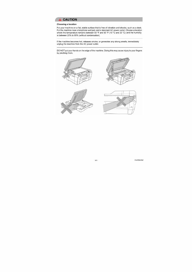
SAFETY INFORMATION
WARNING indicates a potentially hazardous situation which, if not avoided, could result in
death or serious injuries.
CAUTION indicates a potentially hazardous situation which, if not avoided, may result in minor
or moderate injuries.
IMPORTANT indicate a potentially hazardous situation which, if not avoided, may result in
damage to property or loss of product functionality.
Follow all warnings and instructions marked on the machine.
Notes tell you how you should respond to a situation that may arise or give tips about
how the operation works with other features.
Electrical Hazard icons alert you to possible electrical shock.
Improper Setup icons alert you to devices and operations that are not compatible with
the machine.
Fire Hazard icons alert you to the possibility of fire.
WARNING RNING
CAUTION UTION
IMPORTANT
8/15/2019 Brother MFC 6510dw Sm
http://slidepdf.com/reader/full/brother-mfc-6510dw-sm 15/392

8/15/2019 Brother MFC 6510dw Sm
http://slidepdf.com/reader/full/brother-mfc-6510dw-sm 16/392
xiii Confidential
8/15/2019 Brother MFC 6510dw Sm
http://slidepdf.com/reader/full/brother-mfc-6510dw-sm 17/392
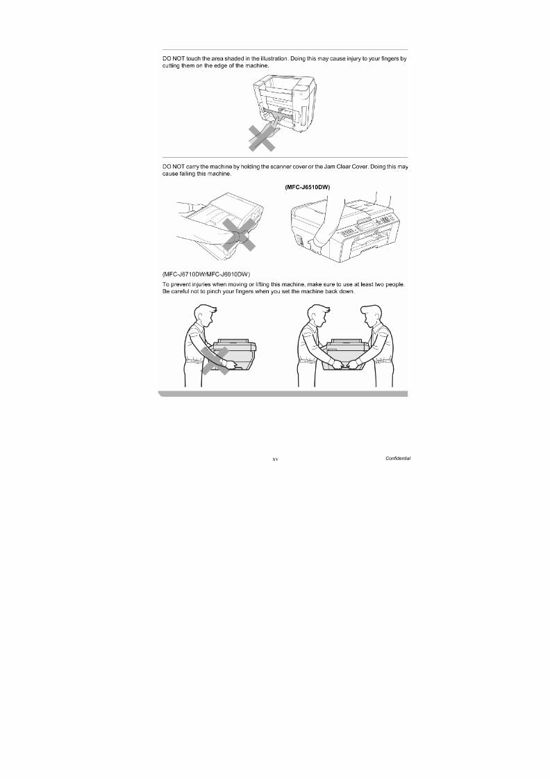
8/15/2019 Brother MFC 6510dw Sm
http://slidepdf.com/reader/full/brother-mfc-6510dw-sm 18/392
xv Confidential

8/15/2019 Brother MFC 6510dw Sm
http://slidepdf.com/reader/full/brother-mfc-6510dw-sm 19/392
xvi Confidential
8/15/2019 Brother MFC 6510dw Sm
http://slidepdf.com/reader/full/brother-mfc-6510dw-sm 20/392
1-1 Confidential
CHAPTER 1 SPECIFICATIONS
This chapter lists the specifications of each model, which enables you to make a comparison of different models.
1.1 GENERAL
1.1.1 General
1.1.2 Media Specifications
Model MFCJ6510DW MFCJ6710DW MFCJ6910DW
Print Head BH11
Minimum Droplet SizeBK: 4 pl
CMY: 1.5 pl
Scanning Method CIS W-CIS
CPU Speed RISC 192 MHz
Backup Clock Yes
Model MFCJ6510DW MFCJ6710DW MFCJ6910DW
Media
Sizes
Standard Tray
A3, A4, LGR, LTR, LGL, EXE, JIS B4, JIS B5, A5, A6, Photo (102 x 152 mm/4 x 6 inches),
Indexcard (127 x 203 mm/5 x 8 inches), Photo-L (89 x 127 mm/3.5 x 5 inches),
Photo-2L (127 x 178 mm/5 x 7 inches), Post Card 1 (100 x 148 mm/3.9 x 5.8 inches),
Post Card 2 (Double) (148 x 200 mm/5.8 x 7.9 inches), C5 Envelope, Com-10,
DL Envelope, Monarch, JE4 Envelope
Photo Tray N/A
Lower Tray N/A JIS B5, EXE, A4/LTR, LGL, JIS B4, A3/LGR
Manual Feed Slot
A3, A4, LGR, LTR, LGL, EXE, JIS B4, JIS B5, A5, A6, Photo (102 x 152 mm/4 x 6 inches),
Indexcard (127 x 203 mm/5 x 8 inches), Photo-L (89 x 127 mm/3.5 x 5 inches),
Photo-2L (127 x 178 mm/5 x 7 inches), Post Card 1 (100 x 148 mm/3.9 x 5.8 inches),
Post Card 2 (Double) (148 x 200 mm/5.8 x 7.9 inches), C5 Envelope, Com-10,
DL Envelope, Monarch, JE4 Envelope
Duplex Print A3/LGR/LGL/A4/LTR/EXE/A5/A6/JIS B4/JIS B5
ADF
(width/length)148/148 mm to 297/431.8 mm (5.8/5.8 inches to 11.7/17.0 inches)
Scanner Glass
(width/length) Up to 297/431.8 mm (Up to 11.7/17.0 inches)
Media
Weights
Standard Tray 64-220 g/m2 (17-58 lb.)
Photo Tray N/A
Lower Tray N/A 64-105 g/m2 (17-28 lb.)
Manual Feed Slot 64-285 g/m2 (17-76 lb.)
Duplex Print 64-105 g/m2 (17-28 lb.)
ADF 64-90 g/m2 (17-24 lb.)
8/15/2019 Brother MFC 6510dw Sm
http://slidepdf.com/reader/full/brother-mfc-6510dw-sm 21/392
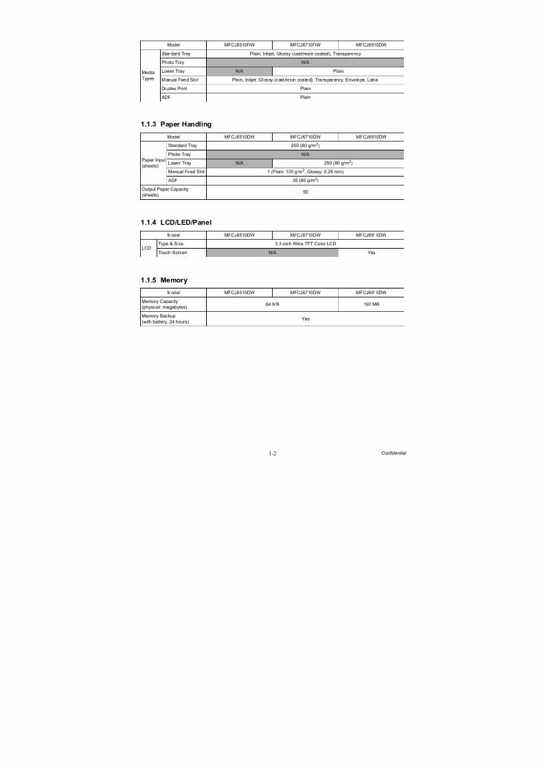
1-2 Confidential
1.1.3 Paper Handling
1.1.4 LCD/LED/Panel
1.1.5 Memory
Model MFCJ6510DW MFCJ6710DW MFCJ6910DW
Media
Types
Standard Tray Plain, Inkjet, Glossy (cast/resin coated), Transparency
Photo Tray N/A
Lower Tray N/A Plain
Manual Feed Slot Pla in, Inkjet , Glossy (cast /resin coated), Transparency, Envelope, Label
Duplex Print Plain
ADF Plain
Model MFCJ6510DW MFCJ6710DW MFCJ6910DW
Paper Input
(sheets)
Standard Tray 250 (80 g/m2)
Photo Tray N/A
Lower Tray N/A 250 (80 g/m2)
Manual Feed Slot 1 (Plain: 120 g/m2
, Glossy: 0.28 mm)
ADF 35 (90 g/m2)
Output Paper Capacity
(sheets)50
Model MFCJ6510DW MFCJ6710DW MFCJ6910DW
LCDType & Size 3.3-inch Wide TFT Color LCD
Touch-Screen N/A Yes
Model MFCJ6510DW MFCJ6710DW MFCJ6910DW
Memory Capacity
(physical: megabytes)64 MB 192 MB
Memory Backup
(with battery, 24 hours)Yes
8/15/2019 Brother MFC 6510dw Sm
http://slidepdf.com/reader/full/brother-mfc-6510dw-sm 22/392
1-3 Confidential
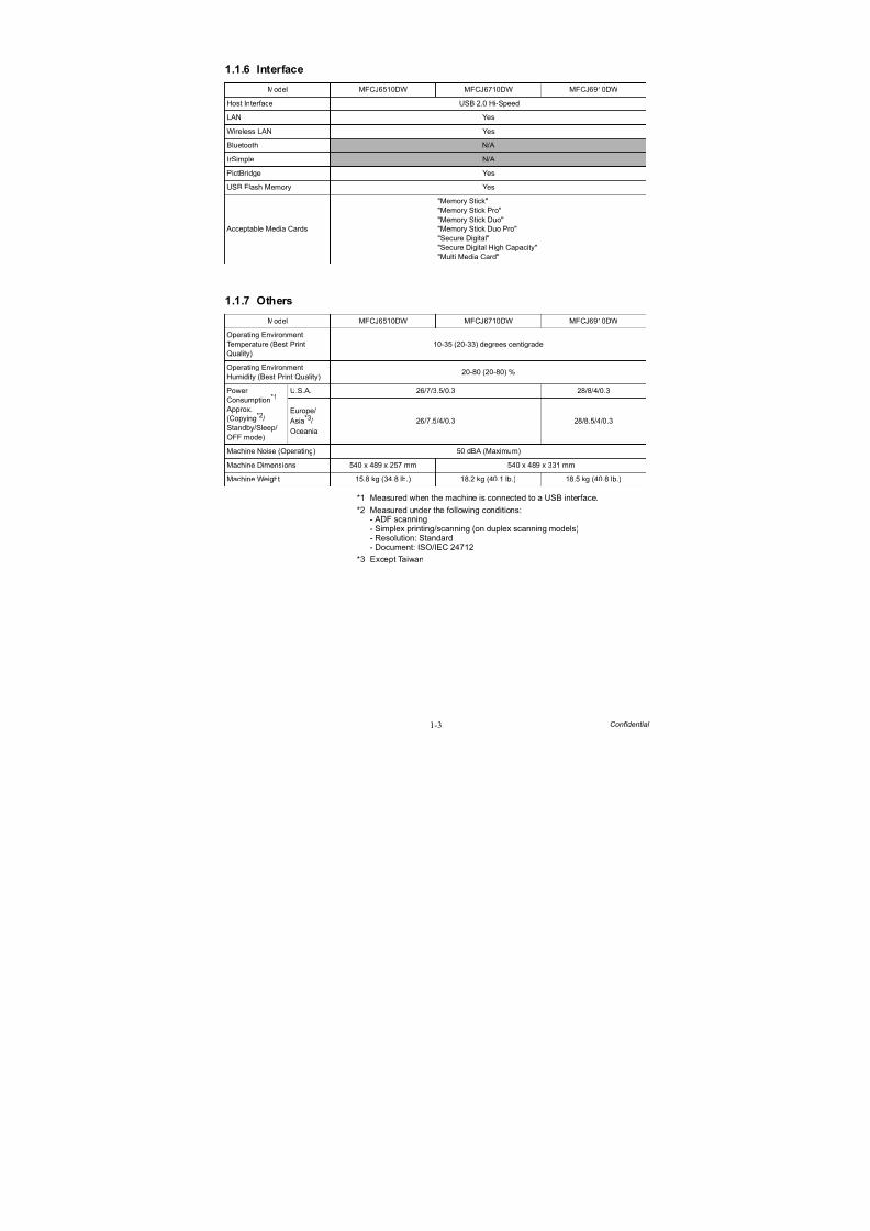
1.1.6 Interface
1.1.7 Others
*1 Measured when the machine is connected to a USB interface.
*2 Measured under the following conditions:- ADF scanning- Simplex printing/scanning (on duplex scanning models)- Resolution: Standard- Document: ISO/IEC 24712
*3 Except Taiwan
Model MFCJ6510DW MFCJ6710DW MFCJ6910DW
Host Interface USB 2.0 Hi-Speed
LAN Yes
Wireless LAN Yes
Bluetooth N/A
IrSimple N/A
PictBridge Yes
USB Flash Memory Yes
Acceptable Media Cards
"Memory Stick"
"Memory Stick Pro"
"Memory Stick Duo"
"Memory Stick Duo Pro"
"Secure Digital"
"Secure Digital High Capacity"
"Multi Media Card"
Model MFCJ6510DW MFCJ6710DW MFCJ6910DW
Operating Environment
Temperature (Best Print
Quality)
10-35 (20-33) degrees centigrade
Operating Environment
Humidity (Best Print Quality)20-80 (20-80) %
Power
Consumption*1
Approx.
(Copying*2/
Standby/Sleep/
OFF mode)
U.S.A. 26/7/3.5/0.3 28/8/4/0.3
Europe/ Asia*3/
Oceania
26/7.5/4/0.3 28/8.5/4/0.3
Machine Noise (Operating) 50 dBA (Maximum)
Machine Dimensions 540 x 489 x 257 mm 540 x 489 x 331 mm
Machine Weight 15.8 kg (34.8 lb.) 18.2 kg (40.1 lb.) 18.5 kg (40.8 lb.)
8/15/2019 Brother MFC 6510dw Sm
http://slidepdf.com/reader/full/brother-mfc-6510dw-sm 23/392
1-4 Confidential
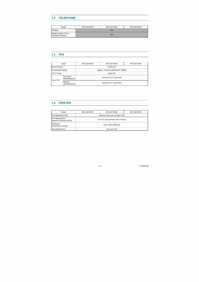
1.2 TELEPHONE
1.3 FAX
1.4 PRINTER
Model MFCJ6510DW MFCJ6710DW MFCJ6910DW
Handset N/A
Digital Cordless Phone
(Cordless Handset)N/A
Model MFCJ6510DW MFCJ6710DW MFCJ6910DW
Modem Speed 33,600 bps
Transmission Speed Approx. 3 seconds (Brother #1, MMR)
ITU-T Group Super G3
Color FAX
Document
(Send/Receive)Yes/Yes (ITU-T color FAX)
Memory
(Send/Receive)No/Yes (ITU-T color FAX)
Model MFCJ6510DW MFCJ6710DW MFCJ6910DW
Print Speed (A4/LTR) Maximum 35/27 ppm (Simplex Print)
Print Speed ESAT
(based on ISO/IEC 24734)12/10 ipm (Normal Mode: 600 x 300 dpi)
Resolution
(horizontal x vertical)
Up to 1200 x 6000 dpi
Auto Duplex Print Yes (up to A3)
8/15/2019 Brother MFC 6510dw Sm
http://slidepdf.com/reader/full/brother-mfc-6510dw-sm 24/392
1-5 Confidential
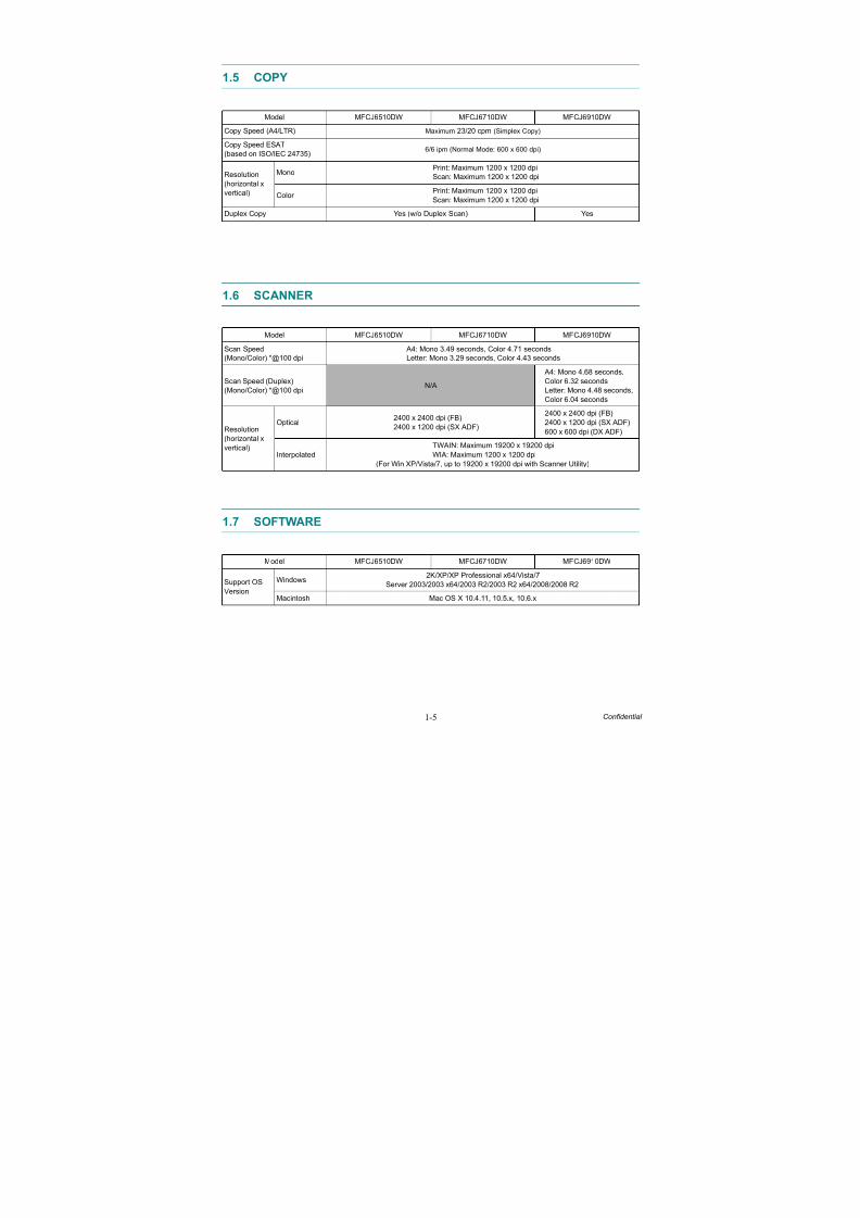
1.5 COPY
1.6 SCANNER
1.7 SOFTWARE
Model MFCJ6510DW MFCJ6710DW MFCJ6910DW
Copy Speed (A4/LTR) Maximum 23/20 cpm (Simplex Copy)
Copy Speed ESAT
(based on ISO/IEC 24735)6/6 ipm (Normal Mode: 600 x 600 dpi)
Resolution
(horizontal x
vertical)
MonoPrint: Maximum 1200 x 1200 dpi
Scan: Maximum 1200 x 1200 dpi
Color Print: Maximum 1200 x 1200 dpi
Scan: Maximum 1200 x 1200 dpi
Duplex Copy Yes (w/o Duplex Scan) Yes
Model MFCJ6510DW MFCJ6710DW MFCJ6910DW
Scan Speed
(Mono/Color) *@100 dpi
A4: Mono 3.49 seconds, Color 4.71 seconds
Letter: Mono 3.29 seconds, Color 4.43 seconds
Scan Speed (Duplex)
(Mono/Color) *@100 dpiN/A
A4: Mono 4.68 seconds,
Color 6.32 seconds
Letter: Mono 4.48 seconds,
Color 6.04 seconds
Resolution
(horizontal x
vertical)
Optical2400 x 2400 dpi (FB)
2400 x 1200 dpi (SX ADF)
2400 x 2400 dpi (FB)
2400 x 1200 dpi (SX ADF)
600 x 600 dpi (DX ADF)
Interpolated
TWAIN: Maximum 19200 x 19200 dpi
WIA: Maximum 1200 x 1200 dpi
(For Win XP/Vista/7, up to 19200 x 19200 dpi with Scanner Utility)
Model MFCJ6510DW MFCJ6710DW MFCJ6910DW
Support OS
Version
Windows2K/XP/XP Professional x64/Vista/7
Server 2003/2003 x64/2003 R2/2003 R2 x64/2008/2008 R2
Macintosh Mac OS X 10.4.11, 10.5.x, 10.6.x
8/15/2019 Brother MFC 6510dw Sm
http://slidepdf.com/reader/full/brother-mfc-6510dw-sm 25/392
1-6 Confidential
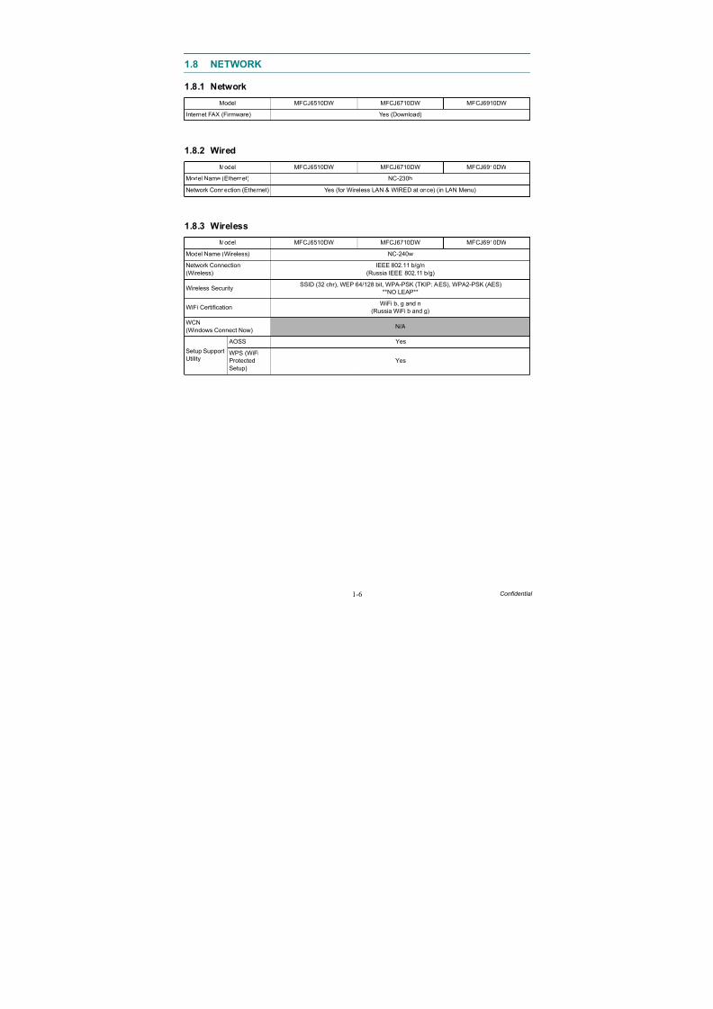
1.8 NETWORK
1.8.1 Network
1.8.2 Wired
1.8.3 Wireless
Model MFCJ6510DW MFCJ6710DW MFCJ6910DW
Internet FAX (Firmware) Yes (Download)
Model MFCJ6510DW MFCJ6710DW MFCJ6910DW
Model Name (Ethernet) NC-230h
Network Connection (Ethernet) Yes (for Wireless LAN & WIRED at once) (in LAN Menu)
Model MFCJ6510DW MFCJ6710DW MFCJ6910DW
Model Name (Wireless) NC-240w
Network Connection
(Wireless)
IEEE 802.11 b/g/n
(Russia IEEE 802.11 b/g)
Wireless SecuritySSID (32 chr), WEP 64/128 bit, WPA-PSK (TKIP: AES), WPA2-PSK (AES)
**NO LEAP**
WiFi CertificationWiFi b, g and n
(Russia WiFi b and g)
WCN
(Windows Connect Now)N/A
Setup Support
Utility
AOSS Yes
WPS (WiFi
Protected
Setup)
Yes
8/15/2019 Brother MFC 6510dw Sm
http://slidepdf.com/reader/full/brother-mfc-6510dw-sm 26/392
1-7 Confidential
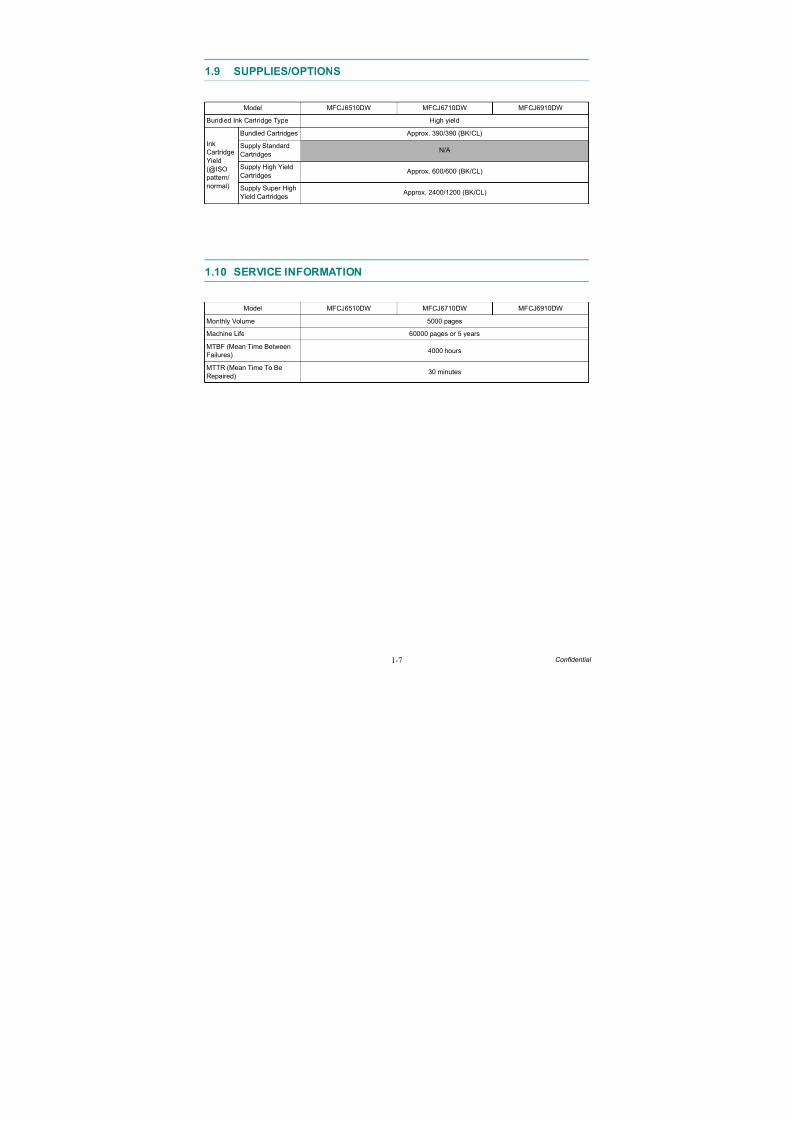
1.9 SUPPLIES/OPTIONS
1.10 SERVICE INFORMATION
Model MFCJ6510DW MFCJ6710DW MFCJ6910DW
Bundled Ink Cartridge Type High yield
Ink
Cartridge
Yield
(@ISO
pattern/
normal)
Bundled Cartridges Approx. 390/390 (BK/CL)
Supply Standard
CartridgesN/A
Supply High Yield
Cartridges Approx. 600/600 (BK/CL)
Supply Super High
Yield Cartridges Approx. 2400/1200 (BK/CL)
Model MFCJ6510DW MFCJ6710DW MFCJ6910DW
Monthly Volume 5000 pages
Machine Life 60000 pages or 5 years
MTBF (Mean Time Between
Failures)4000 hours
MTTR (Mean Time To Be
Repaired)30 minutes
8/15/2019 Brother MFC 6510dw Sm
http://slidepdf.com/reader/full/brother-mfc-6510dw-sm 27/392
8/15/2019 Brother MFC 6510dw Sm
http://slidepdf.com/reader/full/brother-mfc-6510dw-sm 28/392
1-9 Confidential
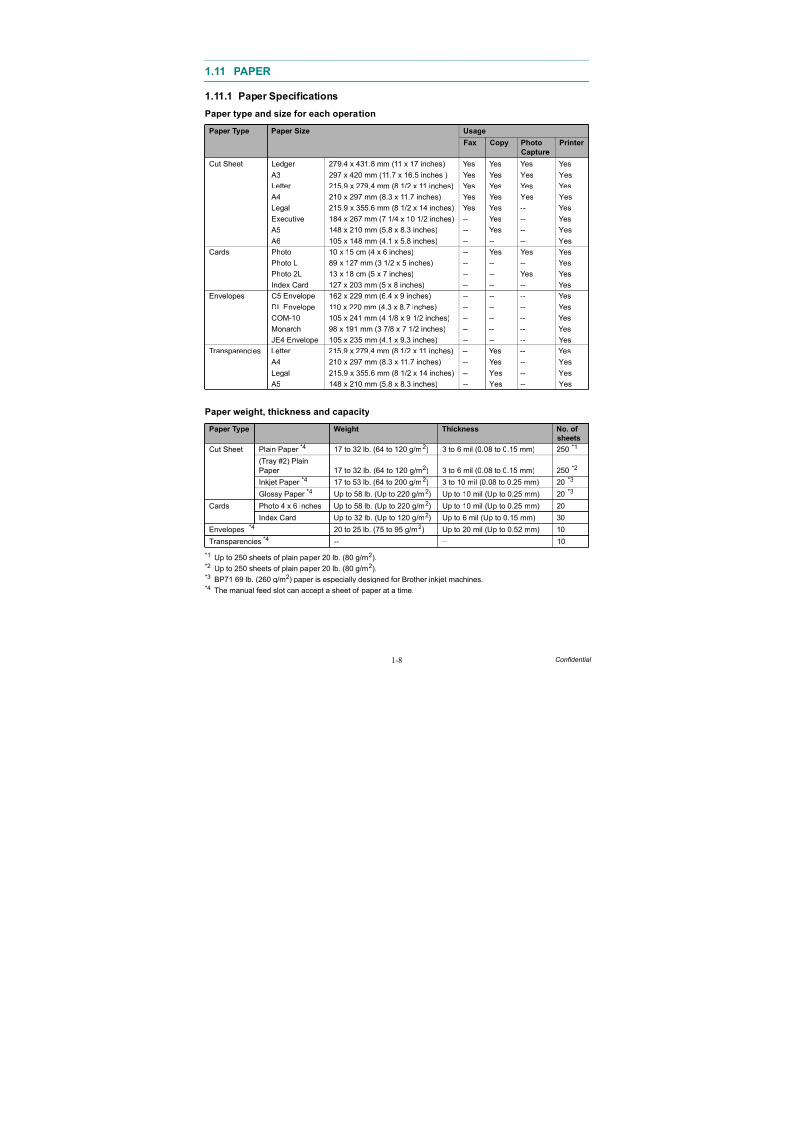
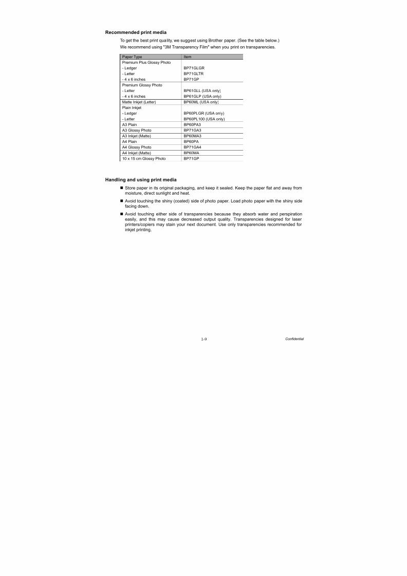
Recommended print media
To get the best print quality, we suggest using Brother paper. (See the table below.)
We recommend using "3M Transparency Film" when you print on transparencies.
Handling and using print media
Store paper in its original packaging, and keep it sealed. Keep the paper flat and away from
moisture, direct sunlight and heat.
Avoid touching the shiny (coated) side of photo paper. Load photo paper with the shiny side
facing down.
Avoid touching either side of transparencies because they absorb water and perspiration
easily, and this may cause decreased output quality. Transparencies designed for laser
printers/copiers may stain your next document. Use only transparencies recommended for
inkjet printing.
Paper Type Item
Premium Plus Glossy Photo- Ledger BP71GLGR
- Letter BP71GLTR
- 4 x 6 inches BP71GP
Premium Glossy Photo
- Letter BP61GLL (USA only)
- 4 x 6 inches BP61GLP (USA only)
Matte Inkjet (Letter) BP60ML (USA only)
Plain Inkjet
- Ledger BP60PLGR (USA only)
- Letter BP60PL100 (USA only)
A3 Plain BP60PA3
A3 Glossy Photo BP71GA3
A3 Inkjet (Matte) BP60MA3
A4 Plain BP60PA
A4 Glossy Photo BP71GA4
A4 Inkjet (Matte) BP60MA
10 x 15 cm Glossy Photo BP71GP
8/15/2019 Brother MFC 6510dw Sm
http://slidepdf.com/reader/full/brother-mfc-6510dw-sm 29/392
1-10 Confidential
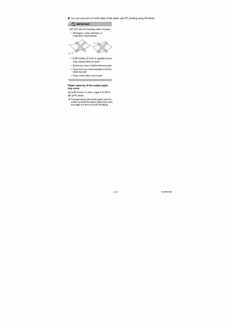
You can only print on both sides of the paper with PC printing using Windows.
1 0.08 inches (2 mm) or greater curve
may cause jams to occur
8/15/2019 Brother MFC 6510dw Sm
http://slidepdf.com/reader/full/brother-mfc-6510dw-sm 30/392
1-11 Confidential
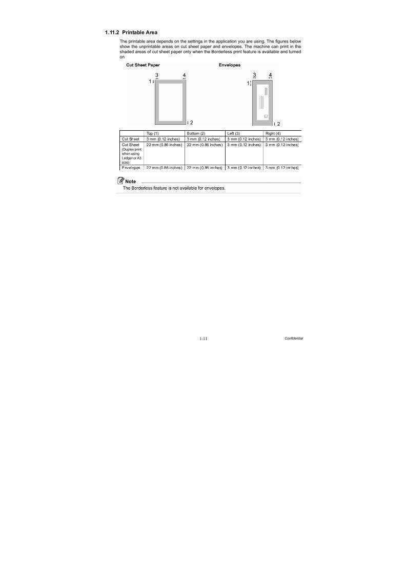
1.11.2 Printable Area
The printable area depends on the settings in the application you are using. The figures below
show the unprintable areas on cut sheet paper and envelopes. The machine can print in the
shaded areas of cut sheet paper only when the Borderless print feature is available and turned
on.
Top (1) Bottom (2) Left (3) Right (4)
Cut Sheet 3 mm (0.12 inches) 3 mm (0.12 inches) 3 mm (0.12 inches) 3 mm (0.12 inches)
Cut Sheet(Duplex print
when using
Ledger or A3
size)
22 mm (0.86 inches) 22 mm (0.86 inches) 3 mm (0.12 inches) 3 mm (0.12 inches)
Envelopes 22 mm (0.86 inches) 22 mm (0.86 inches) 3 mm (0.12 inches) 3 mm (0.12 inches)
8/15/2019 Brother MFC 6510dw Sm
http://slidepdf.com/reader/full/brother-mfc-6510dw-sm 31/392
2-1 Confidential
CHAPTER 2 ERROR INDICATION AND TROUBLESHOOTING
2.1 INTRODUCTION
This section gives the service personnel some of the troubleshooting procedures to be followedif an error or malfunction occurs with the machine. It is impossible to anticipate all of the possible problems which may occur in future and determine the troubleshooting procedures, sothis section covers some sample problems. However, those samples will help service personnel pinpoint and repair other defective elements if he/she analyzes and examines them well.
2.1.1 Precautions
Be sure to observe the following to prevent any secondary troubles from happening duringtroubleshooting.
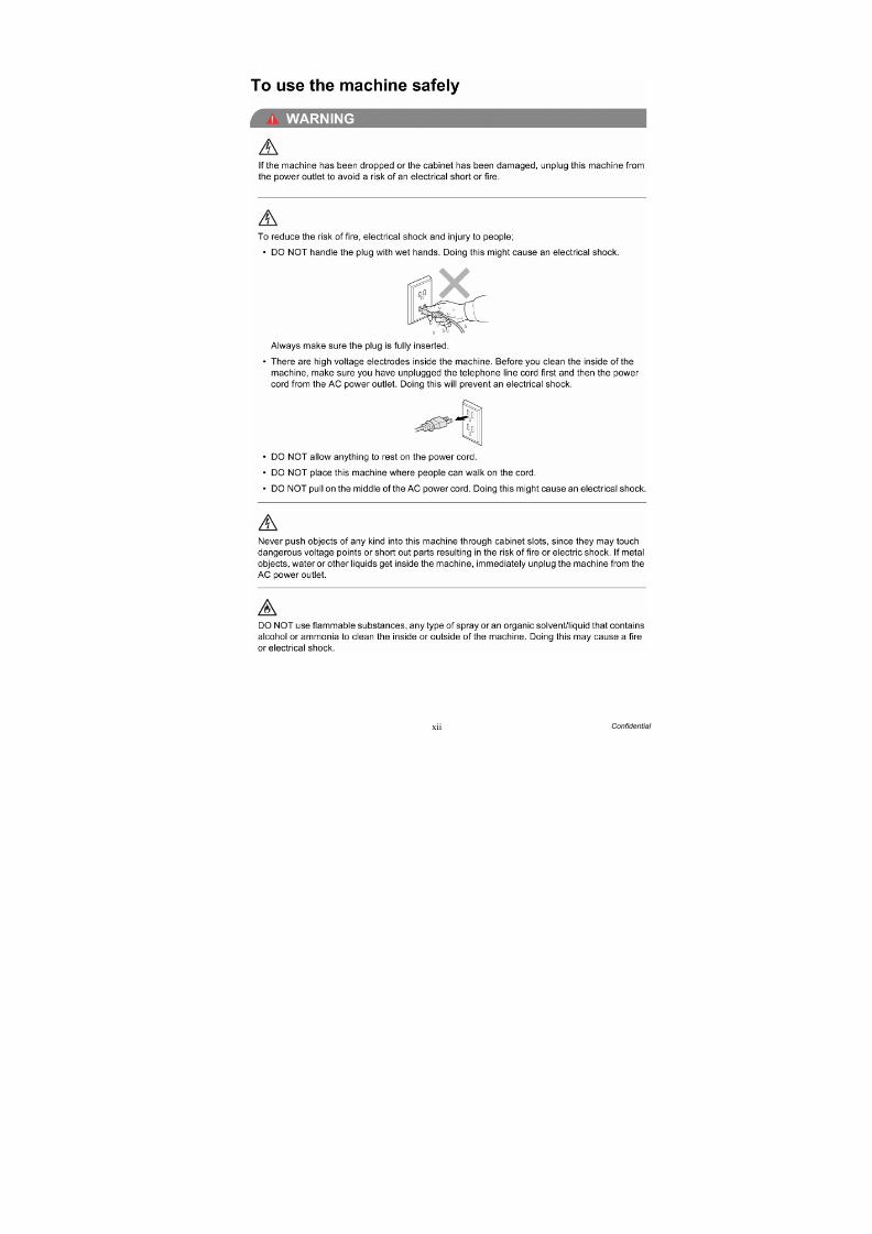
(1) When disconnecting the connectors, do not pull the lead wires but hold the connector housings.
(2) Static electricity charged in your body may damage electronic parts.
Before handling the PCBs, touch a metal portion of the machine to discharge staticelectricity charged in your body. When transporting PCBs, be sure to wrap them inconductive sheets.
When replacing the PCBs, put on a grounding wrist band and perform the job on a staticmat. Also take care not to touch the conductor sections on the flat cables.
(3) Be sure to observe the warnings
(4) After repairing the defective section, be sure to check again if the repaired section workscorrectly.
DO NOT use flammable substances or organic solvent such as alcohol, benzine, thinner or any type of spray to clean the inside or outside of the machine. Doing this may cause a fire or electrical shock.
Always unplug the AC power cord from the outlet when removing the covers and PCBs,adjusting the mechanisms, or conducting continuity testing with a circuit tester.
WARNING RNIN
8/15/2019 Brother MFC 6510dw Sm
http://slidepdf.com/reader/full/brother-mfc-6510dw-sm 32/392
2-2 Confidential
2.1.2 Initial Check
Prior to proceeding to the troubleshooting procedures, make the following initial checks:
Environmental conditions
Check that:(1) The machine is placed on a flat, firm surface.
(2) The machine is used in a clean environment at or near normal room temperature (10°C to35°C) with normal relative humidity (20 to 80%).
(3) The machine is not exposed to direct sunlight, excessive heat, moisture, or dust.
Power requirements
Check that:
(1) The power supply specified on the rating plate on the machine is used. The supply voltage
stays within the rating ±10%.(2) Each voltage level on AC input lines and DC lines is correct.
(3) All cables and harnesses are firmly connected.
(4) The fuses are not blown.
Recording paper
Check that:
(1) A recommended type of recording paper is used. (Refer to Chapter 1, Section 1.11"PAPER.")
(2) The recording paper is not dampened.
Ink cartridges
(1) Check that all of four ink cartridges are loaded.
Head/carriage unit
(1) Repeat the purge operation (Function code 76) several times. (Refer to Chapter 5, Section5.1.4.27.)
8/15/2019 Brother MFC 6510dw Sm
http://slidepdf.com/reader/full/brother-mfc-6510dw-sm 33/392
2-3 Confidential
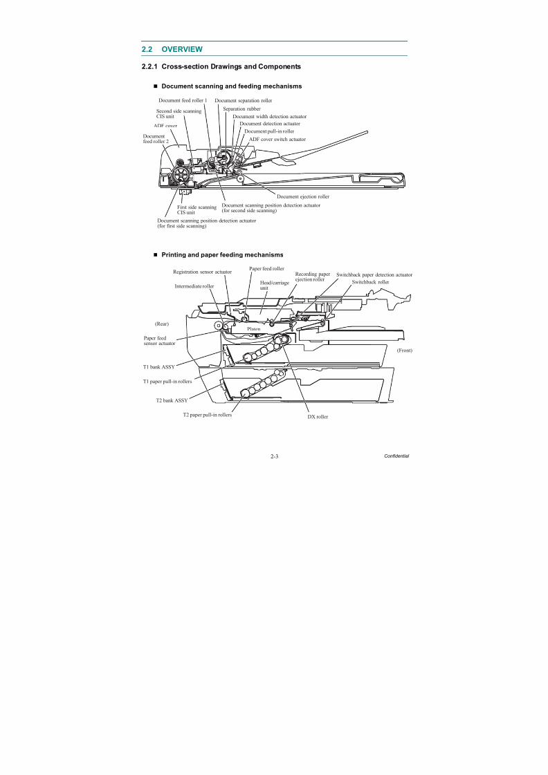
2.2 OVERVIEW
2.2.1 Cross-section Drawings and Components
Document scanning and feeding mechanisms
Printing and paper feeding mechanisms
Second side scanningCIS unit
ADF cover
Documentfeed roller 2
Document scanning position detection actuator(for first side scanning)
First side scanningCIS unit
Document scanning position detection actuator(for second side scanning)
Document ejection roller
ADF cover switch actuator
Document detection actuator
Document pull-in roller
Document width detection actuator
Separation rubber
Document separation roller Document feed roller 1
Paper feedsensor actuator
T1 paper pull-in rollers
T1 bank ASSY
T2 bank ASSY
T2 paper pull-in rollers DX roller
Platen
Head/carriageunitIntermediate roller
Switchback roller
Switchback paper detection actuator Recording paperejection roller
Paper feed roller Registration sensor actuator
(Rear)
(Front)
8/15/2019 Brother MFC 6510dw Sm
http://slidepdf.com/reader/full/brother-mfc-6510dw-sm 34/392
2-4 Confidential
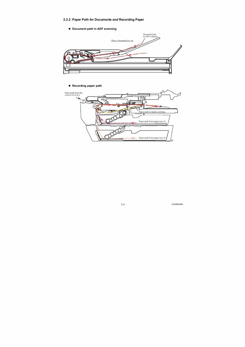
2.2.2 Paper Path for Documents and Recording Paper
Document path in ADF scanning
Recording paper path
Place a document face up
Document pathin ADF scanning
Paper path from themanual feed slot
Paper path from paper tray #2
Paper path in duplex printing
Paper path from paper tray #1
8/15/2019 Brother MFC 6510dw Sm
http://slidepdf.com/reader/full/brother-mfc-6510dw-sm 35/392
2-5 Confidential
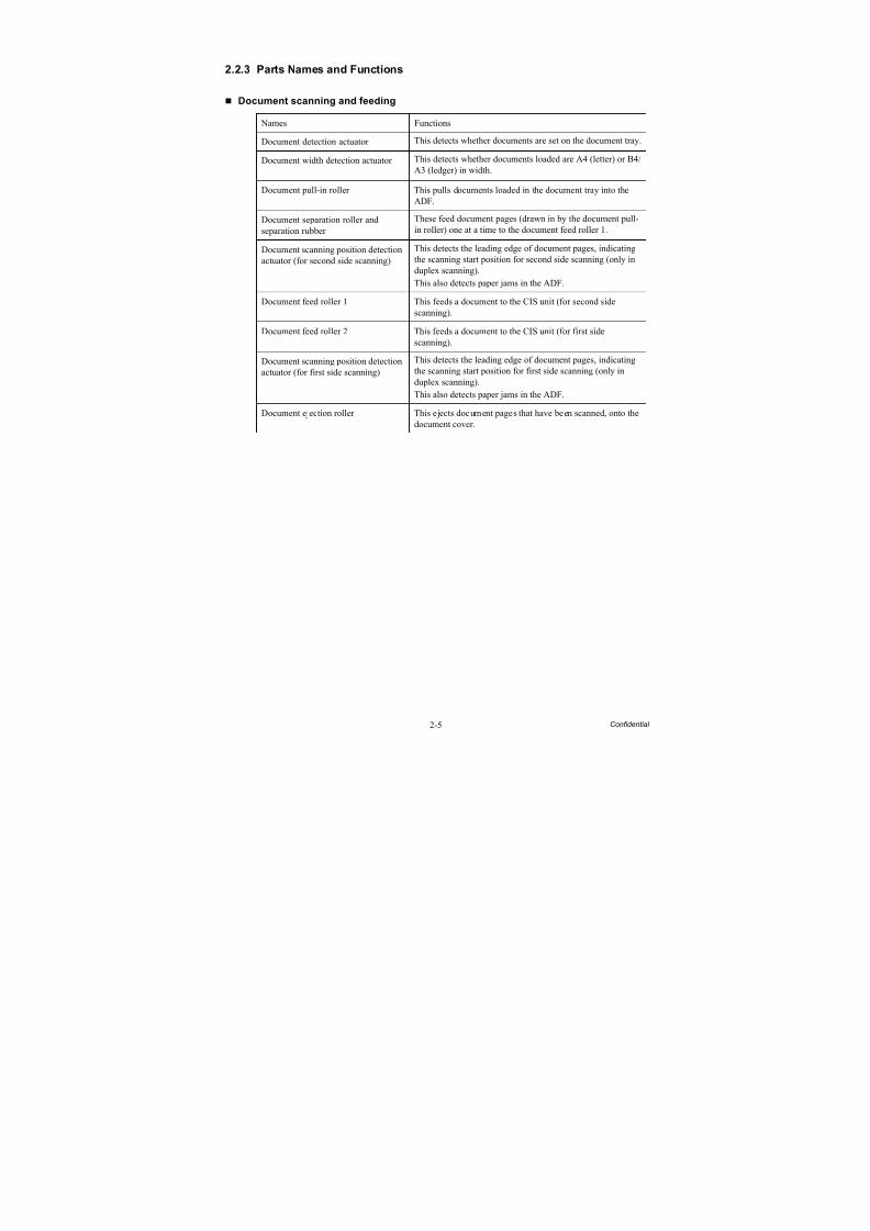
2.2.3 Parts Names and Functions
Document scanning and feeding
Names Functions
Document detection actuator This detects whether documents are set on the document tray.
Document width detection actuator This detects whether documents loaded are A4 (letter) or B4/A3 (ledger) in width.
Document pull-in roller This pulls documents loaded in the document tray into theADF.
Document separation roller andseparation rubber
These feed document pages (drawn in by the document pull-in roller) one at a time to the document feed roller 1.
Document scanning position detectionactuator (for second side scanning)
This detects the leading edge of document pages, indicatingthe scanning start position for second side scanning (only induplex scanning).
This also detects paper jams in the ADF.
Document feed roller 1 This feeds a document to the CIS unit (for second sidescanning).
Document feed roller 2 This feeds a document to the CIS unit (for first sidescanning).
Document scanning position detectionactuator (for first side scanning)
This detects the leading edge of document pages, indicatingthe scanning start position for first side scanning (only induplex scanning).
This also detects paper jams in the ADF.
Document ejection roller This ejects document pages that have been scanned, onto thedocument cover.
8/15/2019 Brother MFC 6510dw Sm
http://slidepdf.com/reader/full/brother-mfc-6510dw-sm 36/392
2-6 Confidential
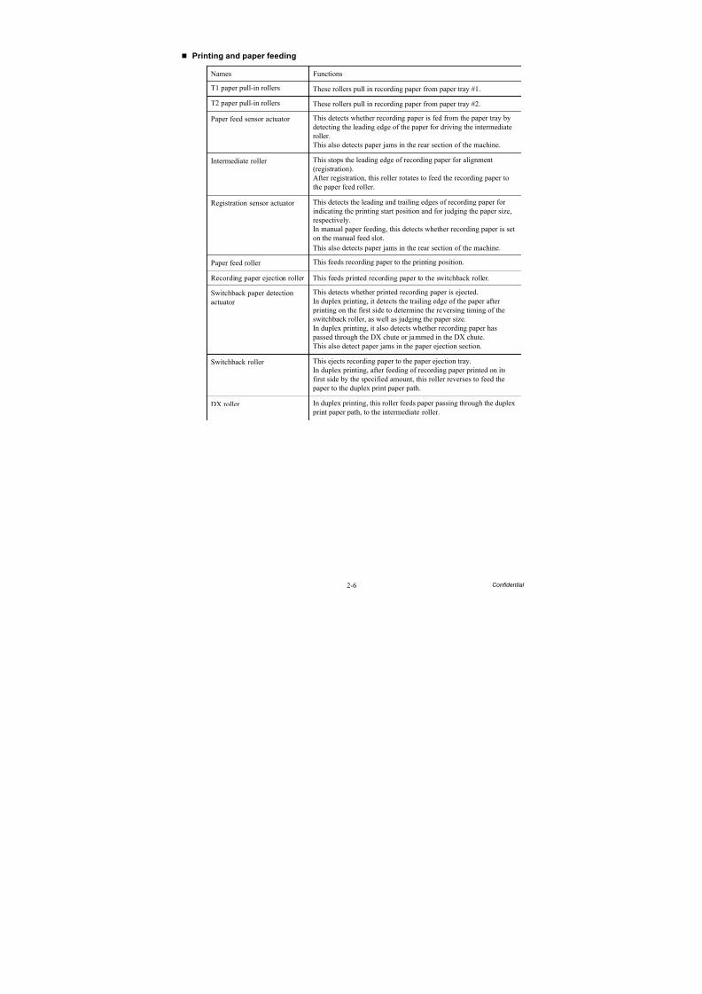
Printing and paper feeding
Names Functions
T1 paper pull-in rollers These rollers pull in recording paper from paper tray #1.
T2 paper pull-in rollers These rollers pull in recording paper from paper tray #2.
Paper feed sensor actuator This detects whether recording paper is fed from the paper tray bydetecting the leading edge of the paper for driving the intermediateroller.This also detects paper jams in the rear section of the machine.
Intermediate roller This stops the leading edge of recording paper for alignment(registration).After registration, this roller rotates to feed the recording paper tothe paper feed roller.
Registration sensor actuator This detects the leading and trailing edges of recording paper forindicating the printing start position and for judging the paper size,
respectively.In manual paper feeding, this detects whether recording paper is seton the manual feed slot.
This also detects paper jams in the rear section of the machine.
Paper feed roller This feeds recording paper to the printing position.
Recording paper ejection roller This feeds printed recording paper to the switchback roller.
Switchback paper detectionactuator
This detects whether printed recording paper is ejected.In duplex printing, it detects the trailing edge of the paper after
printing on the first side to determine the reversing timing of theswitchback roller, as well as judging the paper size.In duplex printing, it also detects whether recording paper has
passed through the DX chute or jammed in the DX chute.This also detect paper jams in the paper ejection section.
Switchback roller This ejects recording paper to the paper ejection tray.In duplex printing, after feeding of recording paper printed on itsfirst side by the specified amount, this roller reverses to feed the
paper to the duplex print paper path.
DX roller In duplex printing, this roller feeds paper passing through the duplex print paper path, to the intermediate roller.
8/15/2019 Brother MFC 6510dw Sm
http://slidepdf.com/reader/full/brother-mfc-6510dw-sm 37/392
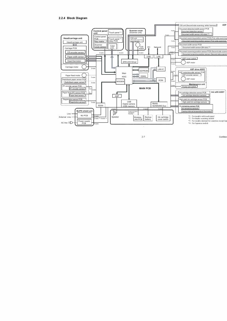
2-7
2.2.4 Block Diagram
[
Control panelunit
Color PC Network
DDR2
Main
ASIC
MODEM
EEPROM
AFE/LED Driver
MAIN PCB
LCD
Carriage motor
Head/carriage unit
Carriage PCB
CR encoder sensor
Paper width sensor
Head thermistor
Head/carriage unit
Paper feed motor
6-wire 4-wire 4-wire
CISmotor
2-wire
2-wire
3-wire
3-wire
4-wire 2-wire2-wire
7-wire
Switchback paper sensor PCB
Switchback paper sensor
PF encoder sensor PCB
MJ PCB
AC line
Line
External Line2-wire
6-wire
2-wire *3 6-wire *4
CIS unit(First side scanning,black harness)
Paper feed (PF) sensor PCB
Registration sensor PCB
Registration sensor
Paper feed sensor
PF encoder sensor4-wire
3-wire
MJ/PS shield unit
AMP
Speaker WirelessLAN PCB
Backupbattery
5-wire in 6-wireconnectorhousing
Ink cartridgecover switch
USBDigital camera
/USB memorySDAA
USB LAN
Control panelPCB
Touch panel *1
Touch panel *1
relay PCB
Ink rema
Casin
Ink re
Docum
Docum
High-yiel
High
Ink cartri
Ink c
Docume
Docu
Docume
Docu
Power supplyPCB
LAN IC
ROM
Purg
CIS unit
ADF
ASF mot
ASF
Docume
Docu
DocumeScanner cover (Scanner unit)
Media
SD/MS/MS Duo
2-wire
2-wire
2-wire
7-wire
4-wire
4-wire
6-wire
3-wire
3-wire
4-wire
3-wire *3
6-wire *4
Key matrix
Scannercover sensor
8/15/2019 Brother MFC 6510dw Sm
http://slidepdf.com/reader/full/brother-mfc-6510dw-sm 38/392
2-8 Confidential
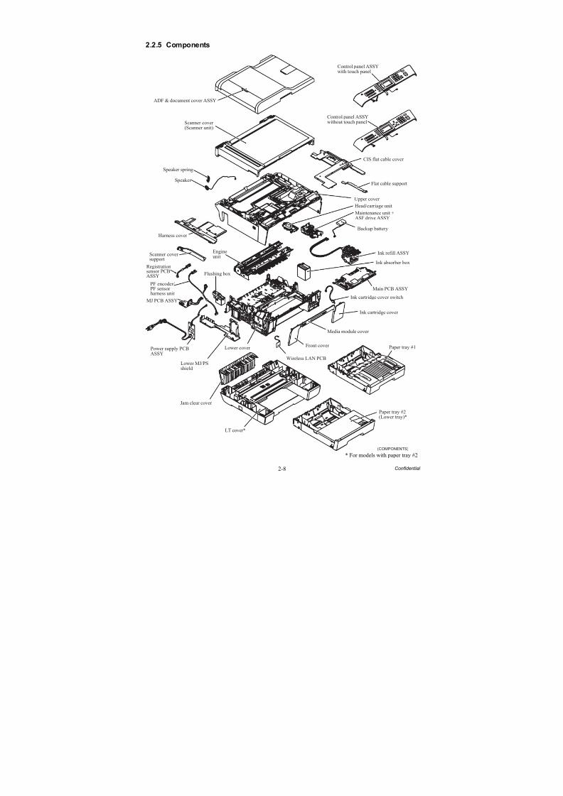
2.2.5 Components
* For models with paper tray #2
Control panel ASSYwith touch panel
(COMPONENTS)
ADF & document cover ASSY
Scanner cover(Scanner unit)
Speaker spring
Speaker
Harness cover
EngineunitScanner cover
support
Registrationsensor PCBASSY
PF encoder/PF sensorharness unit
MJ PCB ASSY
Flushing box
Power supply PCBASSY
Lower MJ/PSshield
Lower cover
Jam clear cover
LT cover*
Paper tray #2(Lower tray)*
Paper tray #1
Wireless LAN PCB
Front cover
Media module cover
Ink cartridge cover
Ink cartridge cover switch
Main PCB ASSY
Ink absorber box
Ink refill ASSY
Backup battery
Head/carriage unit
Maintenance unit +ASF drive ASSY
Upper cover
Flat cable support
CIS flat cable cover
Control panel ASSYwithout touch panel
8/15/2019 Brother MFC 6510dw Sm
http://slidepdf.com/reader/full/brother-mfc-6510dw-sm 39/392
2-9 Confidential
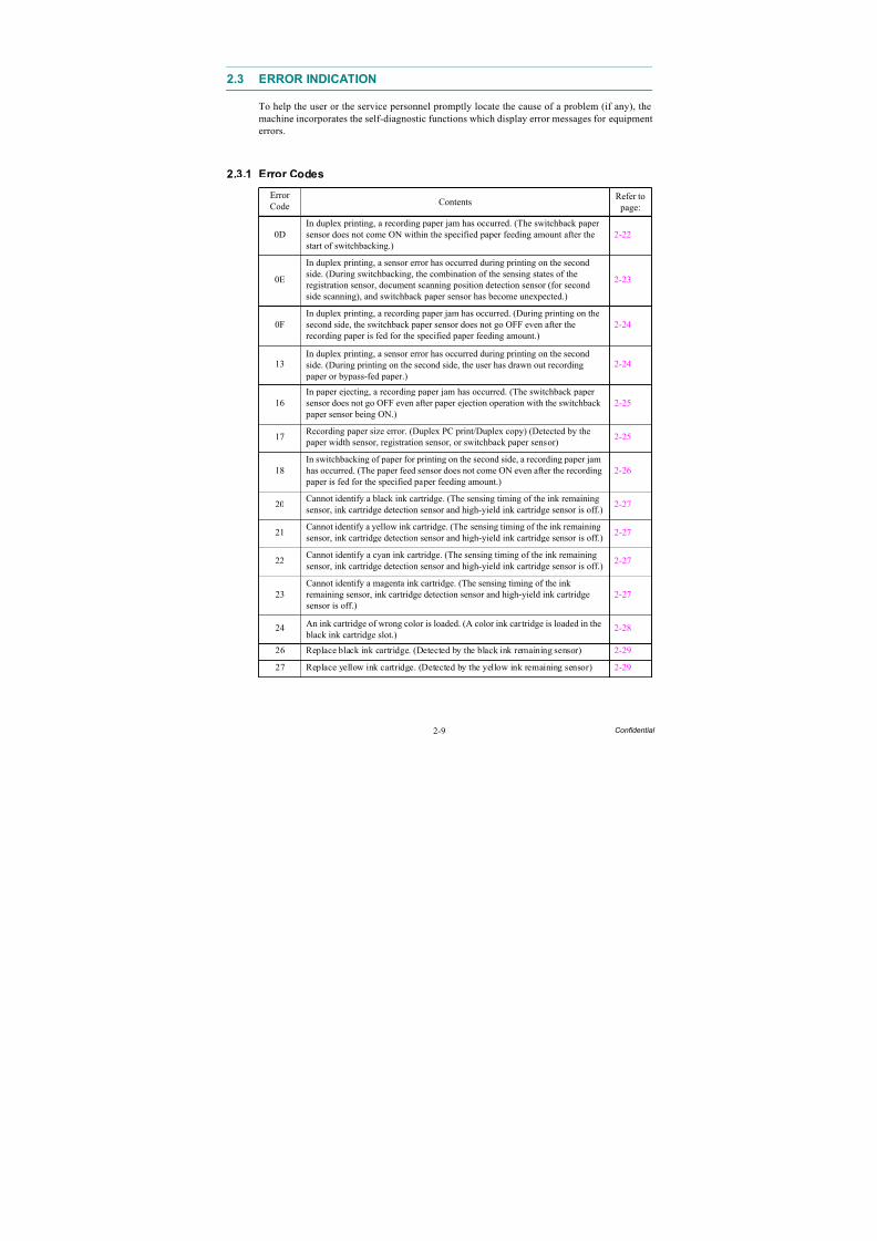
2.3 ERROR INDICATION
To help the user or the service personnel promptly locate the cause of a problem (if any), themachine incorporates the self-diagnostic functions which display error messages for equipmenterrors.
2.3.1 Error Codes
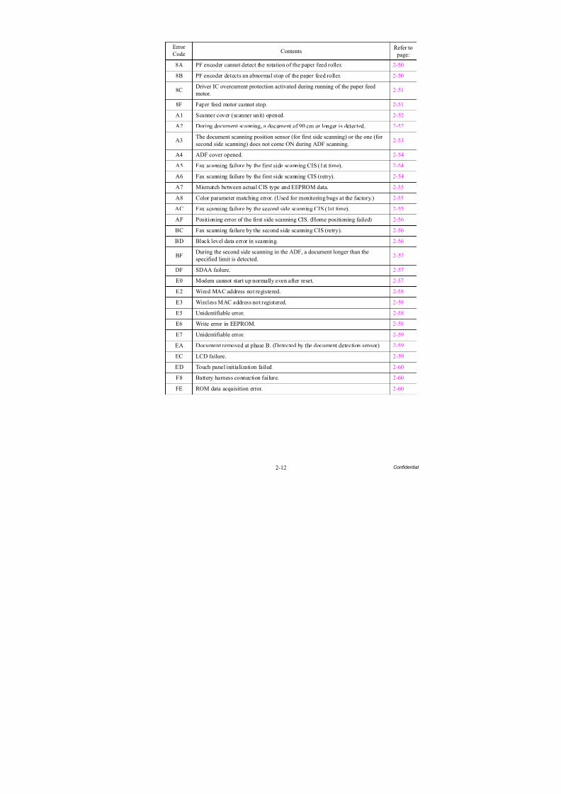
ErrorCode Contents
Refer to page:
0DIn duplex printing, a recording paper jam has occurred. (The switchback papersensor does not come ON within the specified paper feeding amount after thestart of switchbacking.)
2-22
0E
In duplex printing, a sensor error has occurred during printing on the second
side. (During switchbacking, the combination of the sensing states of theregistration sensor, document scanning position detection sensor (for secondside scanning), and switchback paper sensor has become unexpected.)
2-23
0FIn duplex printing, a recording paper jam has occurred. (During printing on thesecond side, the switchback paper sensor does not go OFF even after therecording paper is fed for the specified paper feeding amount.)
2-24
13In duplex printing, a sensor error has occurred during printing on the secondside. (During printing on the second side, the user has drawn out recording
paper or bypass-fed paper.)
2-24
16In paper ejecting, a recording paper jam has occurred. (The switchback papersensor does not go OFF even after paper ejection operation with the switchback
paper sensor being ON.)
2-25
17Recording paper size error. (Duplex PC print/Duplex copy) (Detected by the
paper width sensor, registration sensor, or switchback paper sensor)2-25
18In switchbacking of paper for printing on the second side, a recording paper jamhas occurred. (The paper feed sensor does not come ON even after the recording
paper is fed for the specified paper feeding amount.)2-26
20Cannot identify a black ink cartridge. (The sensing timing of the ink remainingsensor, ink cartridge detection sensor and high-yield ink cartridge sensor is off.)
2-27
21Cannot identify a yellow ink cartridge. (The sensing timing of the ink remainingsensor, ink cartridge detection sensor and high-yield ink cartridge sensor is off.)
2-27
22 Cannot identify a cyan ink cartridge. (The sensing timing of the ink remainingsensor, ink cartridge detection sensor and high-yield ink cartridge sensor is off.) 2-27
23Cannot identify a magenta ink cartridge. (The sensing timing of the inkremaining sensor, ink cartridge detection sensor and high-yield ink cartridgesensor is off.)
2-27
24 An ink cartridge of wrong color is loaded. (A color ink cartridge is loaded in the black ink cartridge slot.)
2-28
26 Replace black ink cartridge. (Detected by the black ink remaining sensor) 2-29
27 Replace yellow ink cartridge. (Detected by the yellow ink remaining sensor) 2-29
8/15/2019 Brother MFC 6510dw Sm
http://slidepdf.com/reader/full/brother-mfc-6510dw-sm 40/392
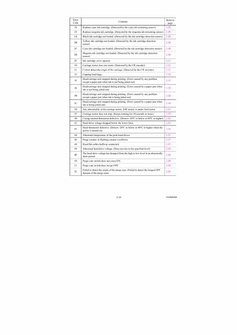
2-10 Confidential
ErrorCode Contents
Refer to page:
28 Replace cyan ink cartridge. (Detected by the cyan ink remaining sensor) 2-29
29 Replace magenta ink cartridge. (Detected by the magenta ink remaining sensor) 2-29
2A Black ink cartridge not loaded. (Detected by the ink cartridge detection sensor) 2-30
2BYellow ink cartridge not loaded. (Detected by the ink cartridge detectionsensor)
2-30
2C Cyan ink cartridge not loaded. (Detected by the ink cartridge detection sensor) 2-30
2DMagenta ink cartridge not loaded. (Detected by the ink cartridge detectionsensor)
2-30
2F Ink cartridge cover opened. 2-31
30 Carriage motor does not rotate. (Detected by the CR encoder) 2-31
31 Cannot detect the origin of the carriage. (Detected by the CR encoder) 2-32
32 Capping load large. 2-32
35Head/carriage unit stopped during printing. (Error caused by any problemexcept a paper jam when ink is not being jetted out)
2-33
38Head/carriage unit stopped during printing. (Error caused by a paper jam whenink is not being jetted out)
2-33
3BHead/carriage unit stopped during printing. (Error caused by any problemexcept a paper jam when ink is being jetted out)
2-34
3CHead/carriage unit stopped during printing. (Error caused by a paper jam whenink is being jetted out)
2-34
3E Any abnormality in the carriage motor, ASF motor, or paper feed motor. 2-35
3F Carriage motor does not stop. (Keeps rotating for 10 seconds or more) 2-35
40 Casing internal thermistor defective. (Detects -20ºC or below or 80ºC or higher) 2-36
42 Head drive voltage dropped below the lower limit. 2-36
43Head thermistor defective. (Detects -20ºC or below or 80ºC or higher when the
power is turned on)2-36
44 Abnormal temperature of the print head driver. 2-37
46 Purge counter or flushing counter overflown. 2-37
48 Head flat cables halfway connected. 2-37
49 Abnormal head drive voltage. (Does not rise to the specified level) 2-38
4FThe head drive voltage has dropped from the high to low level in an abnormallyshort period.
2-38
50 Purge cam switch does not come ON. 2-38
51 Purge cam switch does not go OFF. 2-38
52Failed to detect the origin of the purge cam. (Failed to detect the longest OFFdomain of the purge cam)
2-39
8/15/2019 Brother MFC 6510dw Sm
http://slidepdf.com/reader/full/brother-mfc-6510dw-sm 41/392
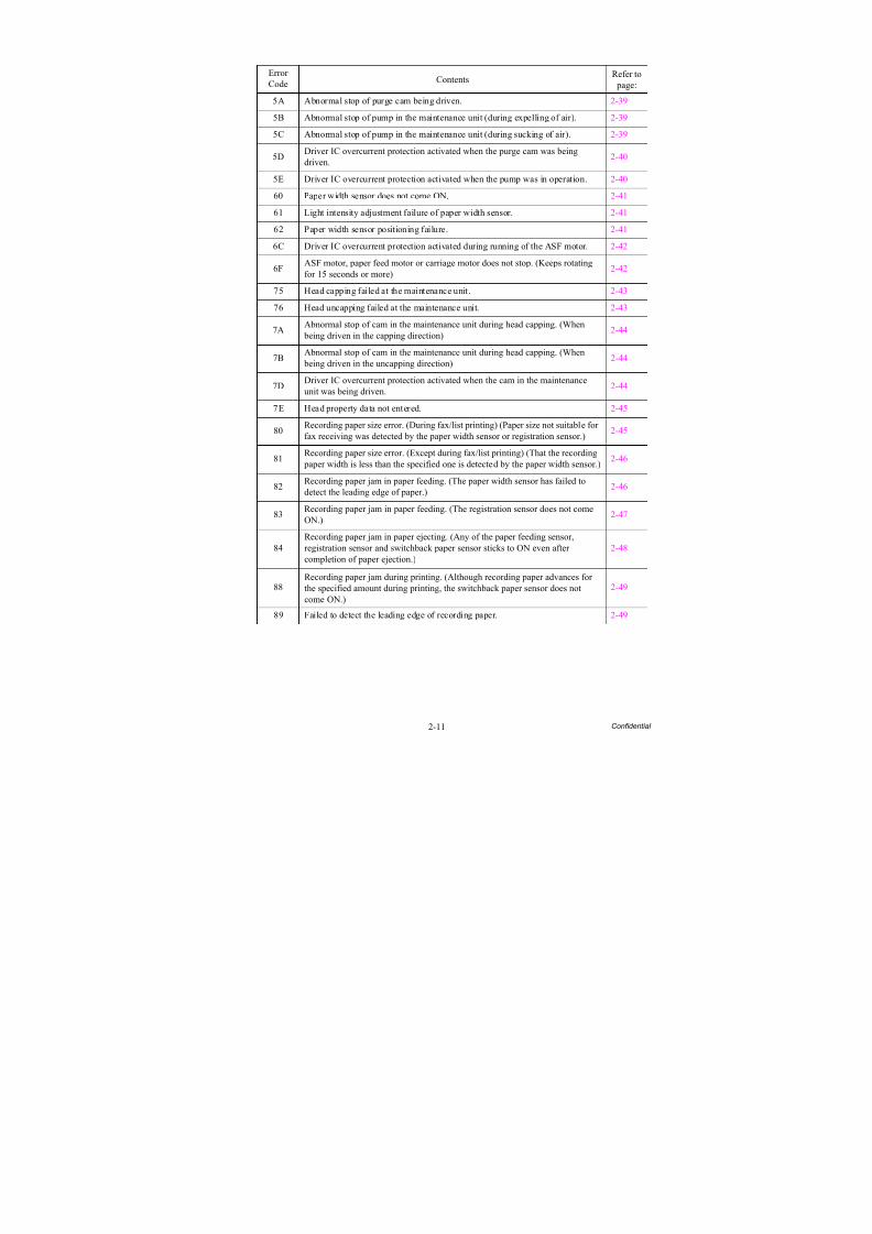
2-11 Confidential
ErrorCode Contents
Refer to page:
5A Abnormal stop of purge cam being driven. 2-39
5B Abnormal stop of pump in the maintenance unit (during expelling of air). 2-39
5C Abnormal stop of pump in the maintenance unit (during sucking of air). 2-39
5DDriver IC overcurrent protection activated when the purge cam was beingdriven.
2-40
5E Driver IC overcurrent protection activated when the pump was in operation. 2-40
60 Paper width sensor does not come ON. 2-41
61 Light intensity adjustment failure of paper width sensor. 2-41
62 Paper width sensor positioning failure. 2-41
6C Driver IC overcurrent protection activated during running of the ASF motor. 2-42
6FASF motor, paper feed motor or carriage motor does not stop. (Keeps rotating
for 15 seconds or more)
2-42
75 Head capping failed at the maintenance unit. 2-43
76 Head uncapping failed at the maintenance unit. 2-43
7AAbnormal stop of cam in the maintenance unit during head capping. (When
being driven in the capping direction)2-44
7BAbnormal stop of cam in the maintenance unit during head capping. (When
being driven in the uncapping direction)2-44
7DDriver IC overcurrent protection activated when the cam in the maintenanceunit was being driven.
2-44
7E Head property data not entered. 2-45
80Recording paper size error. (During fax/list printing) (Paper size not suitable forfax receiving was detected by the paper width sensor or registration sensor.)
2-45
81Recording paper size error. (Except during fax/list printing) (That the recording
paper width is less than the specified one is detected by the paper width sensor.)2-46
82Recording paper jam in paper feeding. (The paper width sensor has failed todetect the leading edge of paper.)
2-46
83Recording paper jam in paper feeding. (The registration sensor does not comeON.)
2-47
84Recording paper jam in paper ejecting. (Any of the paper feeding sensor,registration sensor and switchback paper sensor sticks to ON even aftercompletion of paper ejection.)
2-48
88Recording paper jam during printing. (Although recording paper advances forthe specified amount during printing, the switchback paper sensor does notcome ON.)
2-49
89 Failed to detect the leading edge of recording paper. 2-49
8/15/2019 Brother MFC 6510dw Sm
http://slidepdf.com/reader/full/brother-mfc-6510dw-sm 42/392
2-12 Confidential
ErrorCode Contents
Refer to page:
8A PF encoder cannot detect the rotation of the paper feed roller. 2-50
8B PF encoder detects an abnormal stop of the paper feed roller. 2-50
8C Driver IC overcurrent protection activated during running of the paper feedmotor. 2-51
8F Paper feed motor cannot stop. 2-51
A1 Scanner cover (scanner unit) opened. 2-52
A2 During document scanning, a document of 90 cm or longer is detected. 2-52
A3The document scanning position sensor (for first side scanning) or the one (forsecond side scanning) does not come ON during ADF scanning.
2-53
A4 ADF cover opened. 2-54
A5 Fax scanning failure by the first side scanning CIS (1st time). 2-54
A6 Fax scanning failure by the first side scanning CIS (retry). 2-54A7 Mismatch between actual CIS type and EEPROM data. 2-55
A8 Color parameter matching error. (Used for monitoring bugs at the factory.) 2-55
AC Fax scanning failure by the second side scanning CIS (1st time). 2-55
AF Positioning error of the first side scanning CIS. (Home positioning failed) 2-56
BC Fax scanning failure by the second side scanning CIS (retry). 2-56
BD Black level data error in scanning. 2-56
BFDuring the second side scanning in the ADF, a document longer than thespecified limit is detected.
2-57
DF SDAA failure. 2-57
E0 Modem cannot start up normally even after reset. 2-57
E2 Wired MAC address not registered. 2-58
E3 Wireless MAC address not registered. 2-58
E5 Unidentifiable error. 2-58
E6 Write error in EEPROM. 2-58
E7 Unidentifiable error. 2-59
EA Document removed at phase B. (Detected by the document detection sensor) 2-59
EC LCD failure. 2-59ED Touch panel initialization failed. 2-60
F8 Battery harness connection failure. 2-60
FE ROM data acquisition error. 2-60
8/15/2019 Brother MFC 6510dw Sm
http://slidepdf.com/reader/full/brother-mfc-6510dw-sm 43/392
2-13 Confidential
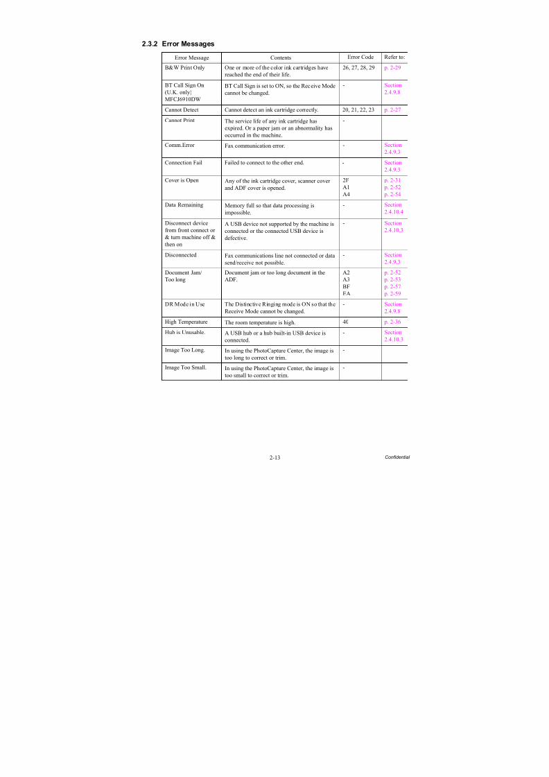
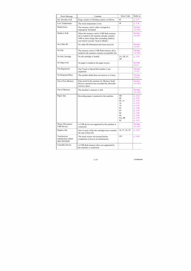
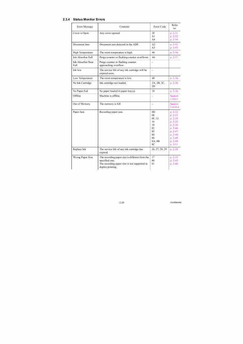
2.3.2 Error Messages
Error Message Contents Error Code Refer to:
B&W Print Only One or more of the color ink cartridges havereached the end of their life.
26, 27, 28, 29 p. 2-29
BT Call Sign On(U.K. only)MFCJ6910DW
BT Call Sign is set to ON, so the Receive Modecannot be changed. - Section2.4.9.8
Cannot Detect Cannot detect an ink cartridge correctly. 20, 21, 22, 23 p. 2-27
Cannot Print The service life of any ink cartridge hasexpired. Or a paper jam or an abnormality hasoccurred in the machine.
-
Comm.Error Fax communication error. - Section2.4.9.3
Connection Fail Failed to connect to the other end. - Section2.4.9.3
Cover is Open Any of the ink cartridge cover, scanner coverand ADF cover is opened.
2FA1A4
p. 2-31 p. 2-52 p. 2-54
Data Remaining Memory full so that data processing isimpossible.
- Section2.4.10.4
Disconnect devicefrom front connect or& turn machine off &then on
A USB device not supported by the machine isconnected or the connected USB device isdefective.
- Section2.4.10.3
Disconnected Fax communications line not connected or data
send/receive not possible.
- Section
2.4.9.3
Document Jam/Too long
Document jam or too long document in theADF.
A2A3BFEA
p. 2-52 p. 2-53 p. 2-57 p. 2-59
DR Mode in Use The Distinctive Ringing mode is ON so that theReceive Mode cannot be changed.
- Section2.4.9.8
High Temperature The room temperature is high. 40 p. 2-36
Hub is Unusable. A USB hub or a hub built-in USB device isconnected.
- Section2.4.10.3
Image Too Long. In using the PhotoCapture Center, the image istoo long to correct or trim.
-
Image Too Small. In using the PhotoCapture Center, the image istoo small to correct or trim.
-
8/15/2019 Brother MFC 6510dw Sm
http://slidepdf.com/reader/full/brother-mfc-6510dw-sm 44/392

8/15/2019 Brother MFC 6510dw Sm
http://slidepdf.com/reader/full/brother-mfc-6510dw-sm 45/392
8/15/2019 Brother MFC 6510dw Sm
http://slidepdf.com/reader/full/brother-mfc-6510dw-sm 46/392
2-16 Confidential
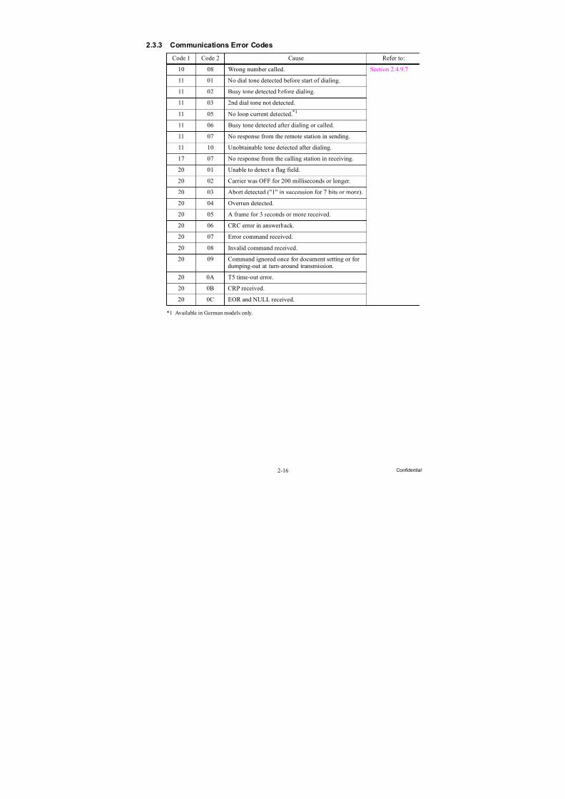
2.3.3 Communications Error Codes
*1 Available in German models only.
Code 1 Code 2 Cause Refer to:
10 08 Wrong number called. Section 2.4.9.7
11 01 No dial tone detected before start of dialing.
11 02 Busy tone detected before dialing.
11 03 2nd dial tone not detected.
11 05 No loop current detected.*1
11 06 Busy tone detected after dialing or called.
11 07 No response from the remote station in sending.
11 10 Unobtainable tone detected after dialing.
17 07 No response from the calling station in receiving.
20 01 Unable to detect a flag field.
20 02 Carrier was OFF for 200 milliseconds or longer.
20 03 Abort detected ("1" in succession for 7 bits or more).
20 04 Overrun detected.
20 05 A frame for 3 seconds or more received.
20 06 CRC error in answerback.
20 07 Error command received.
20 08 Invalid command received.
20 09 Command ignored once for document setting or for
dumping-out at turn-around transmission.20 0A T5 time-out error.
20 0B CRP received.
20 0C EOR and NULL received.
8/15/2019 Brother MFC 6510dw Sm
http://slidepdf.com/reader/full/brother-mfc-6510dw-sm 47/392
2-17 Confidential
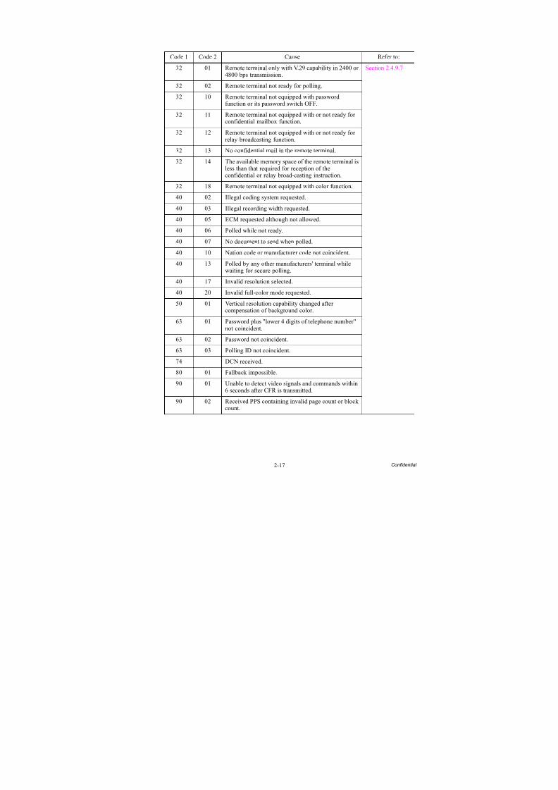
Code 1 Code 2 Cause Refer to:
32 01 Remote terminal only with V.29 capability in 2400 or4800 bps transmission.
Section 2.4.9.7
32 02 Remote terminal not ready for polling.32 10 Remote terminal not equipped with password
function or its password switch OFF.
32 11 Remote terminal not equipped with or not ready forconfidential mailbox function.
32 12 Remote terminal not equipped with or not ready forrelay broadcasting function.
32 13 No confidential mail in the remote terminal.
32 14 The available memory space of the remote terminal isless than that required for reception of the
confidential or relay broad-casting instruction.32 18 Remote terminal not equipped with color function.
40 02 Illegal coding system requested.
40 03 Illegal recording width requested.
40 05 ECM requested although not allowed.
40 06 Polled while not ready.
40 07 No document to send when polled.
40 10 Nation code or manufacturer code not coincident.
40 13 Polled by any other manufacturers' terminal whilewaiting for secure polling.
40 17 Invalid resolution selected.
40 20 Invalid full-color mode requested.
50 01 Vertical resolution capability changed aftercompensation of background color.
63 01 Password plus "lower 4 digits of telephone number"not coincident.
63 02 Password not coincident.
63 03 Polling ID not coincident.
74 DCN received.
80 01 Fallback impossible.
90 01 Unable to detect video signals and commands within6 seconds after CFR is transmitted.
90 02 Received PPS containing invalid page count or blockcount.
8/15/2019 Brother MFC 6510dw Sm
http://slidepdf.com/reader/full/brother-mfc-6510dw-sm 48/392
2-18 Confidential
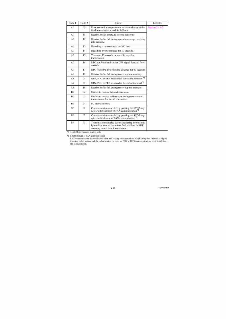
*1 Available in German models only.
*2 Establishment of FAX communicationFAX communication is established when the calling station receives a DIS (reception capability) signalfrom the called station and the called station receives an NSS or DCS (communications test) signal from
the calling station.
Code 1 Code 2 Cause Refer to:
A0 03 Error correction sequence not terminated even at thefinal transmission speed for fallback.
Section 2.4.9.7
A0 11 Receive buffer empty. (5-second time-out)A0 12 Receive buffer full during operation except receiving
into memory.
A0 13 Decoding error continued on 500 lines.
A0 14 Decoding error continued for 10 seconds.
A0 15 Time-out: 13 seconds or more for one-linetransmission.
A0 16 RTC not found and carrier OFF signal detected for 6seconds.
A0 17 RTC found but no command detected for 60 seconds.
A0 19 Receive buffer full during receiving into memory.
A8 01 RTN, PIN, or ERR received at the calling terminal.*1
A9 01 RTN, PIN, or ERR received at the called terminal.*1
AA 18 Receive buffer full during receiving into memory.
B0 02 Unable to receive the next-page data.
B0 03 Unable to receive polling even during turn-aroundtransmission due to call reservation.
B0 04 PC interface error.
BF 01 Communication canceled by pressing the STOP keybefore establishment of FAX communication*2.
BF 02 Communication canceled by pressing the STOP keyafter establishment of FAX communication*2.
BF 03 Transmission canceled due to a scanning error caused by no document or document feed problem in ADFscanning in real time transmission.
8/15/2019 Brother MFC 6510dw Sm
http://slidepdf.com/reader/full/brother-mfc-6510dw-sm 49/392
2-19 Confidential
Code 1 Code 2 Cause Refer to:
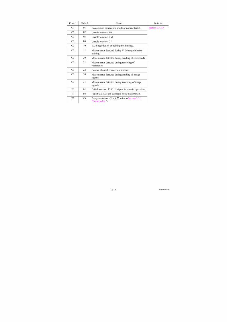
C0 01 No common modulation mode or polling failed. Section 2.4.9.7
C0 02 Unable to detect JM.
C0 03 Unable to detect CM.
C0 04 Unable to detect CJ.
C0 10 V. 34 negotiation or training not finished.
C0 11 Modem error detected during V. 34 negotiation ortraining.
C0 20 Modem error detected during sending of commands.
C0 21 Modem error detected during receiving ofcommands.
C0 22 Control channel connection timeout.
C0 30 Modem error detected during sending of imagesignals.
C0 31 Modem error detected during receiving of imagesignals.
E0 01 Failed to detect 1300 Hz signal in burn-in operation.
E0 02 Failed to detect PB signals in burn-in operation.
FF XX Equipment error. (For X X, refer to Section 2.3.1"Error Codes.")
8/15/2019 Brother MFC 6510dw Sm
http://slidepdf.com/reader/full/brother-mfc-6510dw-sm 50/392

8/15/2019 Brother MFC 6510dw Sm
http://slidepdf.com/reader/full/brother-mfc-6510dw-sm 51/392
2-21 Confidential
Error Message Contents Error CodeRefer
to:
Unable to Print 3X Errors around the head/carriage unit. 30 to 3F pp. 2-31to 2-35
Unable to Print 5X Errors around the maintenance unit. 50 to 5E pp. 2-38to 2-40
Unable to Print 7X 75 to 7E pp. 2-43to 2-45
Unable to Scan AX Errors around the scanner. A2 to AF pp. 2-52to 2-56
Unable to Print XX Errors other than 3X, 5X, 7X, and AX. Codes otherthan 3X, 5X,7X and AX
pp. 2-36to 2-60
8/15/2019 Brother MFC 6510dw Sm
http://slidepdf.com/reader/full/brother-mfc-6510dw-sm 52/392
2-22 Confidential
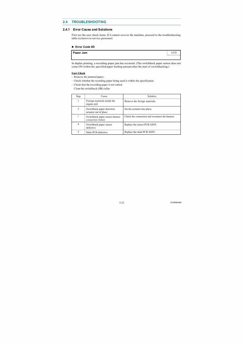
2.4 TROUBLESHOOTING
2.4.1 Error Cause and Solutions
First see the user check items. If it cannot recover the machine, proceed to the troubleshooting
table exclusive to service personnel.
Error Code 0D
In duplex printing, a recording paper jam has occurred. (The switchback paper sensor does notcome ON within the specified paper feeding amount after the start of switchbacking.)
User Check
- Remove the jammed paper.- Check whether the recording paper being used is within the specification.
- Check that the recording paper is not curled.
- Clean the switchback (SB) roller.
Paper Jam LCD
Step Cause Solution
1 Foreign materials inside theengine unit
Remove the foreign materials.
2 Switchback paper detectionactuator out of place
Set the actuator into place.
3 Switchback paper sensor harnessconnection failure
Check the connection and reconnect the harness.
4 Switchback paper sensordefective
Replace the sensor PCB ASSY.
5 Main PCB defective Replace the main PCB ASSY.
8/15/2019 Brother MFC 6510dw Sm
http://slidepdf.com/reader/full/brother-mfc-6510dw-sm 53/392
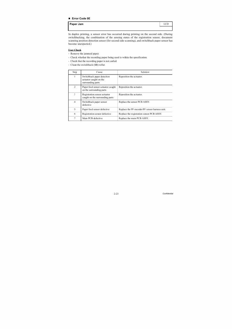
2-23 Confidential
Error Code 0E
In duplex printing, a sensor error has occurred during printing on the second side. (During
switchbacking, the combination of the sensing states of the registration sensor, documentscanning position detection sensor (for second side scanning), and switchback paper sensor has become unexpected.)
User Check
- Remove the jammed paper.
- Check whether the recording paper being used is within the specification.
- Check that the recording paper is not curled.
- Clean the switchback (SB) roller.
Paper Jam LCD
Step Cause Solution
1 Switchback paper detectionactuator caught on thesurrounding parts
Reposition the actuator.
2 Paper feed sensor actuator caughton the surrounding parts
Reposition the actuator.
3 Registration sensor actuatorcaught on the surrounding parts
Reposition the actuator.
4 Switchback paper sensordefective
Replace the sensor PCB ASSY.
5 Paper feed sensor defective Replace the PF encoder/PF sensor harness unit.
6 Registration sensor defective Replace the registration sensor PCB ASSY.
7 Main PCB defective Replace the main PCB ASSY.
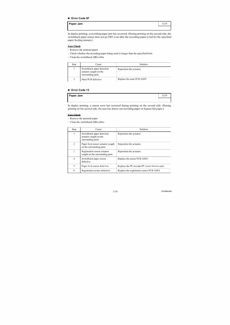
8/15/2019 Brother MFC 6510dw Sm
http://slidepdf.com/reader/full/brother-mfc-6510dw-sm 54/392
2-24 Confidential
Error Code 0F
In duplex printing, a recording paper jam has occurred. (During printing on the second side, the
switchback paper sensor does not go OFF even after the recording paper is fed for the specified paper feeding amount.)
User Check
- Remove the jammed paper.
- Check whether the recording paper being used is longer than the specified limit.
- Clean the switchback (SB) roller.
Error Code 13
In duplex printing, a sensor error has occurred during printing on the second side. (During
printing on the second side, the user has drawn out recording paper or bypass-fed paper.)
User Check
- Remove the jammed paper
- Clean the switchback (SB) roller..
Paper Jam LCD
Step Cause Solution
1 Switchback paper detection
actuator caught on thesurrounding parts
Reposition the actuator.
2 Main PCB defective Replace the main PCB ASSY.
Paper Jam LCD
Step Cause Solution
1 Switchback paper detectionactuator caught on thesurrounding parts
Reposition the actuator.
2 Paper feed sensor actuator caughton the surrounding parts
Reposition the actuator.
3 Registration sensor actuatorcaught on the surrounding parts
Reposition the actuator.
4 Switchback paper sensordefective
Replace the sensor PCB ASSY.
5 Paper feed sensor defective Replace the PF encoder/PF sensor harness unit.
6 Registration sensor defective Replace the registration sensor PCB ASSY.
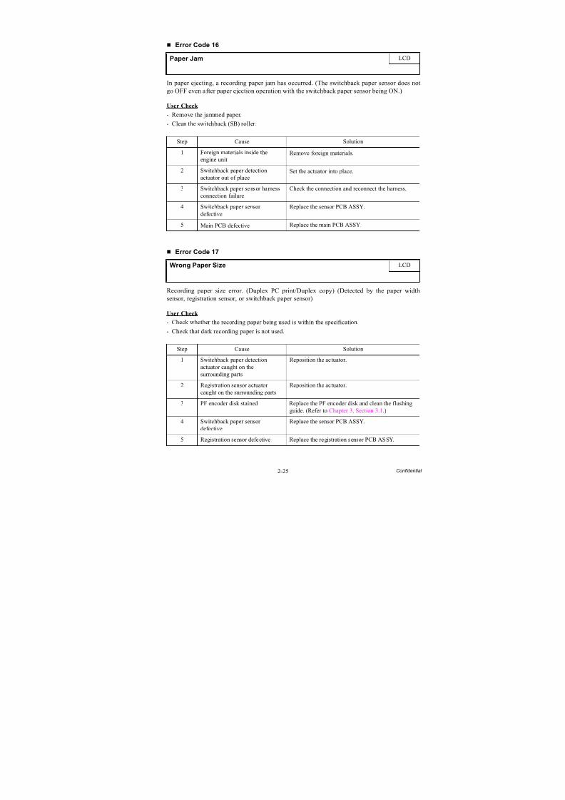
8/15/2019 Brother MFC 6510dw Sm
http://slidepdf.com/reader/full/brother-mfc-6510dw-sm 55/392
2-25 Confidential
Error Code 16
In paper ejecting, a recording paper jam has occurred. (The switchback paper sensor does not
go OFF even after paper ejection operation with the switchback paper sensor being ON.)
User Check
- Remove the jammed paper.
- Clean the switchback (SB) roller.
Error Code 17
Recording paper size error. (Duplex PC print/Duplex copy) (Detected by the paper widthsensor, registration sensor, or switchback paper sensor)
User Check
- Check whether the recording paper being used is within the specification.
- Check that dark recording paper is not used.
Paper Jam LCD
Step Cause Solution
1 Foreign materials inside theengine unit
Remove foreign materials.
2 Switchback paper detection
actuator out of place
Set the actuator into place.
3 Switchback paper sensor harnessconnection failure
Check the connection and reconnect the harness.
4 Switchback paper sensordefective
Replace the sensor PCB ASSY.
5 Main PCB defective Replace the main PCB ASSY.
Wrong Paper Size LCD
Step Cause Solution
1 Switchback paper detectionactuator caught on thesurrounding parts
Reposition the actuator.
2 Registration sensor actuatorcaught on the surrounding parts
Reposition the actuator.
3 PF encoder disk stained Replace the PF encoder disk and clean the flushingguide. (Refer to Chapter 3, Section 3.1.)
4 Switchback paper sensordefective
Replace the sensor PCB ASSY.
5 Registration sensor defective Replace the registration sensor PCB ASSY.
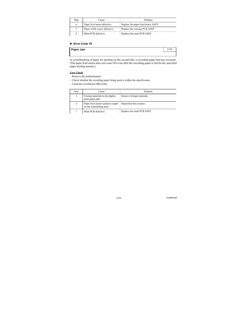
8/15/2019 Brother MFC 6510dw Sm
http://slidepdf.com/reader/full/brother-mfc-6510dw-sm 56/392
2-26 Confidential
Error Code 18
In switchbacking of paper for printing on the second side, a recording paper jam has occurred.(The paper feed sensor does not come ON even after the recording paper is fed for the specified paper feeding amount.)
User Check
- Remove the jammed paper.- Check whether the recording paper being used is within the specification.
- Clean the switchback (SB) roller.
Step Cause Solution
6 Paper feed motor defective Replace the paper feed motor ASSY.
7 Paper width sensor defective Replace the carriage PCB ASSY.
8 Main PCB defective Replace the main PCB ASSY.
Paper Jam LCD
Step Cause Solution
1 Foreign materials in the duplex print paper path
Remove foreign materials.
2 Paper feed sensor actuator caughton the surrounding parts
Reposition the actuator.
3 Main PCB defective Replace the main PCB ASSY.
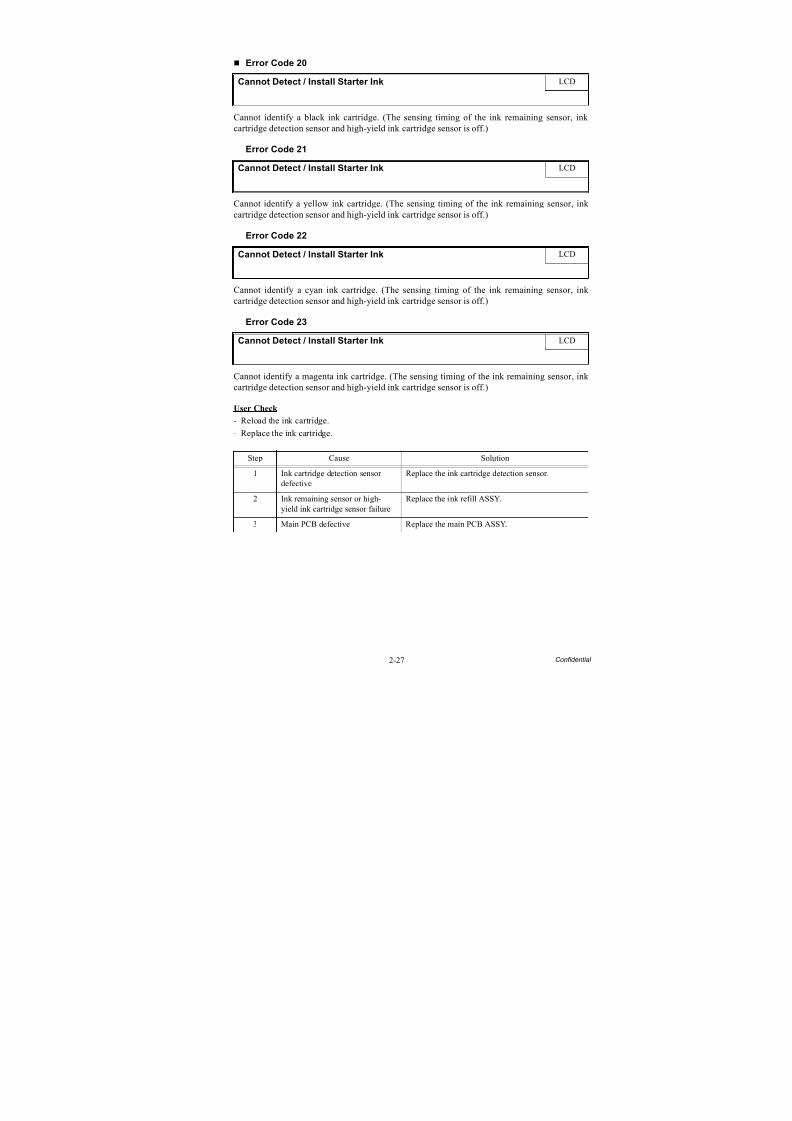
8/15/2019 Brother MFC 6510dw Sm
http://slidepdf.com/reader/full/brother-mfc-6510dw-sm 57/392
2-27 Confidential
Error Code 20
Cannot identify a black ink cartridge. (The sensing timing of the ink remaining sensor, ink
cartridge detection sensor and high-yield ink cartridge sensor is off.)
Error Code 21
Cannot identify a yellow ink cartridge. (The sensing timing of the ink remaining sensor, ink cartridge detection sensor and high-yield ink cartridge sensor is off.)
Error Code 22
Cannot identify a cyan ink cartridge. (The sensing timing of the ink remaining sensor, ink cartridge detection sensor and high-yield ink cartridge sensor is off.)
Error Code 23
Cannot identify a magenta ink cartridge. (The sensing timing of the ink remaining sensor, ink cartridge detection sensor and high-yield ink cartridge sensor is off.)
User Check
- Reload the ink cartridge.
- Replace the ink cartridge.
Cannot Detect / Install Starter Ink LCD
Cannot Detect / Install Starter Ink LCD
Cannot Detect / Install Starter Ink LCD
Cannot Detect / Install Starter Ink LCD
Step Cause Solution
1 Ink cartridge detection sensordefective
Replace the ink cartridge detection sensor.
2 Ink remaining sensor or high-yield ink cartridge sensor failure Replace the ink refill ASSY.
3 Main PCB defective Replace the main PCB ASSY.

8/15/2019 Brother MFC 6510dw Sm
http://slidepdf.com/reader/full/brother-mfc-6510dw-sm 58/392
2-28 Confidential
Error Code 24
An ink cartridge of wrong color is loaded. (A color ink cartridge is loaded in the black ink
cartridge slot.)
User Check
- Load the ink cartridge into place.
- Replace the ink cartridge.
Wrong INK Color LCD
Step Cause Solution
1 Ink cartridge detection sensordefective
Replace the ink cartridge detection sensor.
2 Ink remaining sensor or high-
yield ink cartdige sensor failure
Replace the ink refill ASSY.
3 Main PCB defective Replace the main PCB ASSY.
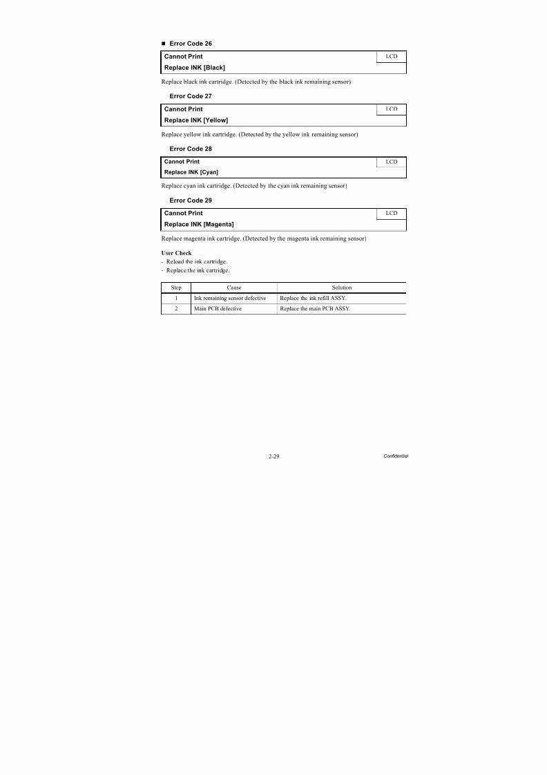
8/15/2019 Brother MFC 6510dw Sm
http://slidepdf.com/reader/full/brother-mfc-6510dw-sm 59/392
2-29 Confidential
Error Code 26
Replace black ink cartridge. (Detected by the black ink remaining sensor)
Error Code 27
Replace yellow ink cartridge. (Detected by the yellow ink remaining sensor)
Error Code 28
Replace cyan ink cartridge. (Detected by the cyan ink remaining sensor)
Error Code 29
Replace magenta ink cartridge. (Detected by the magenta ink remaining sensor)
User Check
- Reload the ink cartridge.- Replace the ink cartridge.
Cannot Print LCD
Replace INK [Black]
Cannot Print LCD
Replace INK [Yellow]
Cannot Print LCD
Replace INK [Cyan]
Cannot Print LCD
Replace INK [Magenta]
Step Cause Solution
1 Ink remaining sensor defective Replace the ink refill ASSY.
2 Main PCB defective Replace the main PCB ASSY.
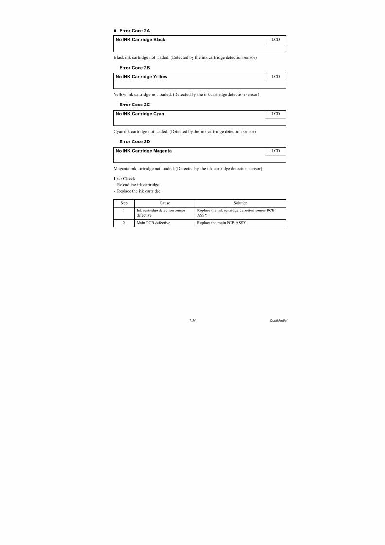
8/15/2019 Brother MFC 6510dw Sm
http://slidepdf.com/reader/full/brother-mfc-6510dw-sm 60/392
2-30 Confidential
Error Code 2A
Black ink cartridge not loaded. (Detected by the ink cartridge detection sensor)
Error Code 2B
Yellow ink cartridge not loaded. (Detected by the ink cartridge detection sensor)
Error Code 2C
Cyan ink cartridge not loaded. (Detected by the ink cartridge detection sensor)
Error Code 2D
Magenta ink cartridge not loaded. (Detected by the ink cartridge detection sensor)
User Check
- Reload the ink cartridge.- Replace the ink cartridge.
No INK Cartridge Black LCD
No INK Cartridge Yellow LCD
No INK Cartridge Cyan LCD
No INK Cartridge Magenta LCD
Step Cause Solution
1 Ink cartridge detection sensordefective
Replace the ink cartridge detection sensor PCBASSY.
2 Main PCB defective Replace the main PCB ASSY.
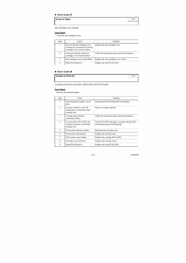
8/15/2019 Brother MFC 6510dw Sm
http://slidepdf.com/reader/full/brother-mfc-6510dw-sm 61/392
2-31 Confidential
Error Code 2F
Ink cartridge cover opened.
User Check
- Close the ink cartridge cover.
Error Code 30
Carriage motor does not rotate. (Detected by the CR encoder)
User Check
- Remove the jammed paper.
Cover is Open LCD
Step Cause Solution
1 Boss on the ink cartridge cover,working as an actuator for the inkcartridge cover switch, broken
Replace the ink cartridge cover.
2 Connection failure of the inkcartridge cover switch harness
Check the connection and reconnect the harness.
3 Ink cartridge cover switch failure Replace the ink cartridge cover switch.
4 Main PCB defective Replace the main PCB ASSY.
Unable to Print 30 LCD
Step Cause Solution
1 CR timing belt or pulley out of place
Reposition the CR timing belt or the pulley.
2 Foreign materials on the CRtiming belt or around the head/carriage unit
Remove foreign materials.
3 Carriage motor harness
connection failure
Check the connection and reconnect the harness.
4 Leveler roller (LR) ASSY notmounted correctly on the head/carriage unit
Set the LR ASSY into place, using the LR jigs (LR positioning jig and LR fitting jig).
5 CR encoder strip out of place Reposition the encoder strip.
6 CR encoder strip stained Replace the encoder strip.
7 CR encoder sensor failure Replace the carriage PCB ASSY.
8 Carriage motor defective Replace the carriage motor.
9 Main PCB defective Replace the main PCB ASSY.
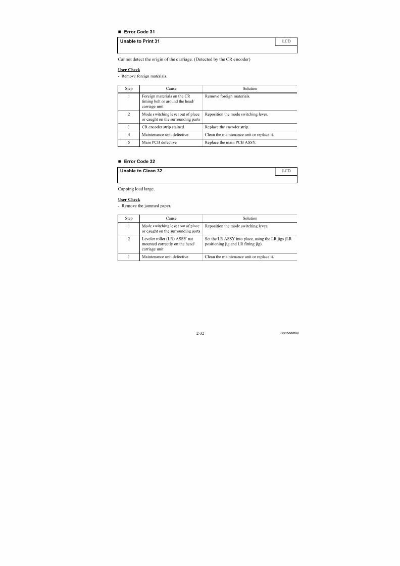
8/15/2019 Brother MFC 6510dw Sm
http://slidepdf.com/reader/full/brother-mfc-6510dw-sm 62/392
2-32 Confidential
Error Code 31
Cannot detect the origin of the carriage. (Detected by the CR encoder)
User Check
- Remove foreign materials.
Error Code 32
Capping load large.
User Check
- Remove the jammed paper.
Unable to Print 31 LCD
Step Cause Solution
1 Foreign materials on the CRtiming belt or around the head/carriage unit
Remove foreign materials.
2 Mode switching lever out of placeor caught on the surrounding parts
Reposition the mode switching lever.
3 CR encoder strip stained Replace the encoder strip.4 Maintenance unit defective Clean the maintenance unit or replace it.
5 Main PCB defective Replace the main PCB ASSY.
Unable to Clean 32 LCD
Step Cause Solution
1 Mode switching lever out of placeor caught on the surrounding parts
Reposition the mode switching lever.
2 Leveler roller (LR) ASSY notmounted correctly on the head/carriage unit
Set the LR ASSY into place, using the LR jigs (LR positioning jig and LR fitting jig).
3 Maintenance unit defective Clean the maintenance unit or replace it.
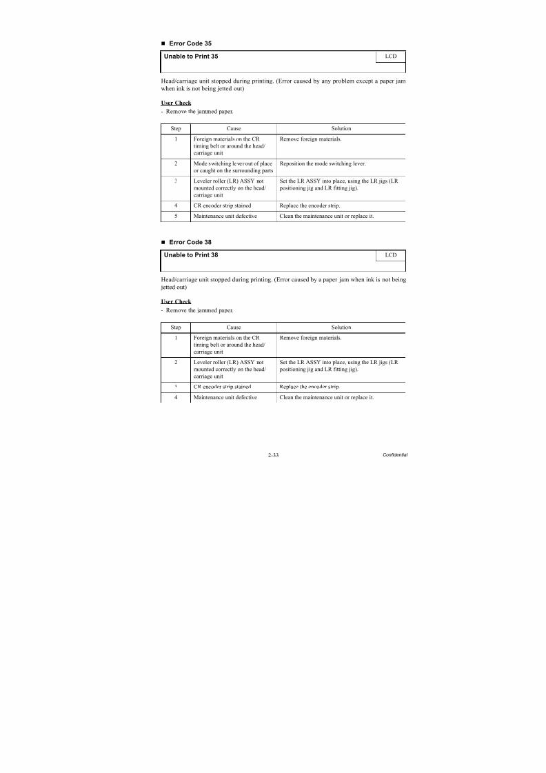
8/15/2019 Brother MFC 6510dw Sm
http://slidepdf.com/reader/full/brother-mfc-6510dw-sm 63/392
2-33 Confidential
Error Code 35
Head/carriage unit stopped during printing. (Error caused by any problem except a paper jam
when ink is not being jetted out)
User Check
- Remove the jammed paper.
Error Code 38
Head/carriage unit stopped during printing. (Error caused by a paper jam when ink is not being jetted out)
User Check
- Remove the jammed paper.
Unable to Print 35 LCD
Step Cause Solution
1 Foreign materials on the CRtiming belt or around the head/carriage unit
Remove foreign materials.
2 Mode switching lever out of place
or caught on the surrounding parts
Reposition the mode switching lever.
3 Leveler roller (LR) ASSY notmounted correctly on the head/carriage unit
Set the LR ASSY into place, using the LR jigs (LR positioning jig and LR fitting jig).
4 CR encoder strip stained Replace the encoder strip.
5 Maintenance unit defective Clean the maintenance unit or replace it.
Unable to Print 38 LCD
Step Cause Solution
1 Foreign materials on the CR
timing belt or around the head/carriage unit
Remove foreign materials.
2 Leveler roller (LR) ASSY notmounted correctly on the head/carriage unit
Set the LR ASSY into place, using the LR jigs (LR positioning jig and LR fitting jig).
3 CR encoder strip stained Replace the encoder strip.
4 Maintenance unit defective Clean the maintenance unit or replace it.
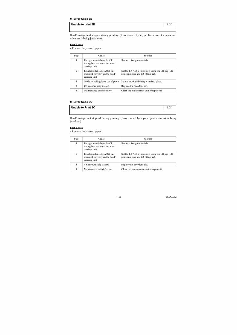
8/15/2019 Brother MFC 6510dw Sm
http://slidepdf.com/reader/full/brother-mfc-6510dw-sm 64/392
2-34 Confidential
Error Code 3B
Head/carriage unit stopped during printing. (Error caused by any problem except a paper jam
when ink is being jetted out)
User Check
- Remove the jammed paper.
Error Code 3C
Head/carriage unit stopped during printing. (Error caused by a paper jam when ink is being jetted out)
User Check
- Remove the jammed paper.
Unable to print 3B LCD
Step Cause Solution
1 Foreign materials on the CRtiming belt or around the head/carriage unit
Remove foreign materials.
2 Leveler roller (LR) ASSY not
mounted correctly on the head/carriage unit
Set the LR ASSY into place, using the LR jigs (LR
positioning jig and LR fitting jig).
3 Mode switching lever out of place Set the mode switching lever into place.
4 CR encoder strip stained Replace the encoder strip.
5 Maintenance unit defective Clean the maintenance unit or replace it.
Unable to Print 3C LCD
Step Cause Solution
1 Foreign materials on the CRtiming belt or around the head/
carriage unit
Remove foreign materials.
2 Leveler roller (LR) ASSY notmounted correctly on the head/carriage unit
Set the LR ASSY into place, using the LR jigs (LR positioning jig and LR fitting jig).
3 CR encoder strip stained Replace the encoder strip.
4 Maintenance unit defective Clean the maintenance unit or replace it.
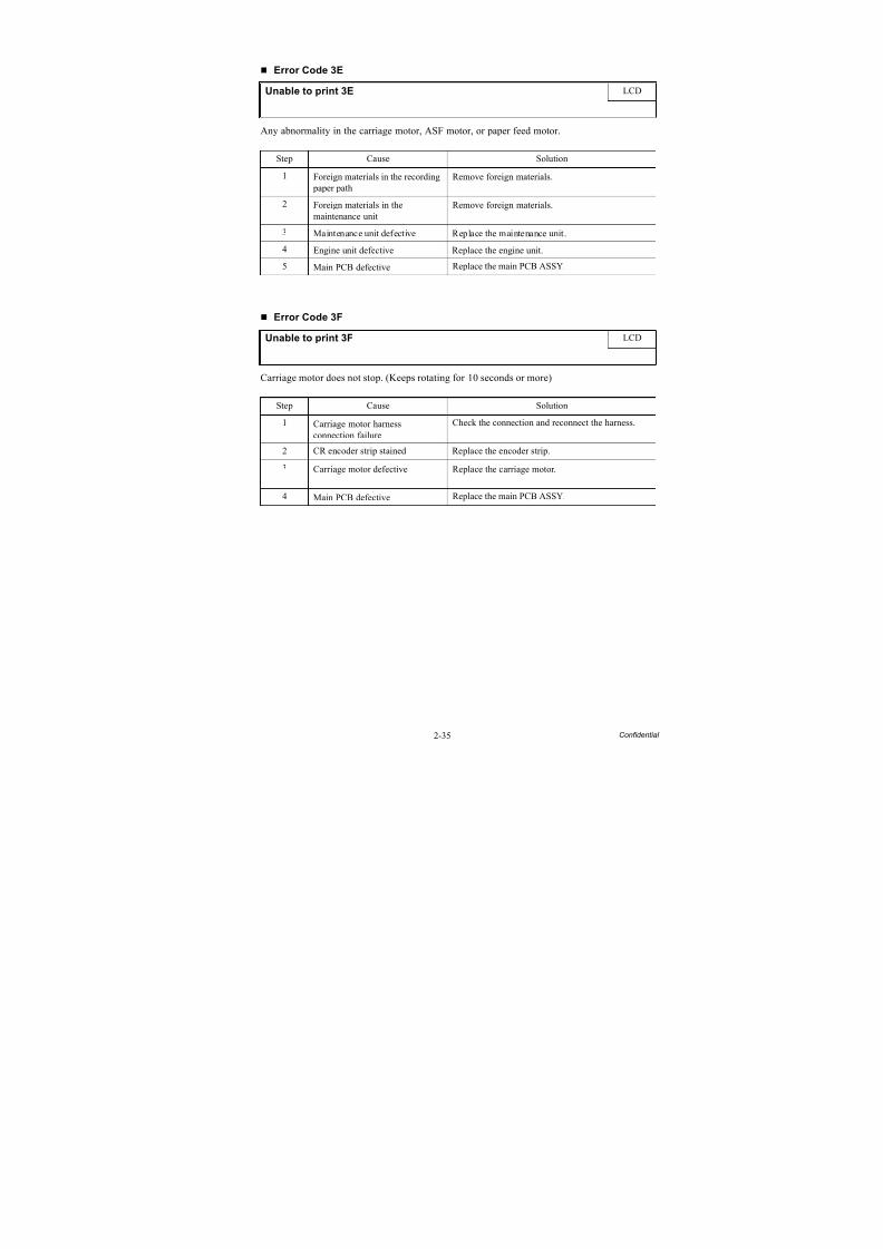
8/15/2019 Brother MFC 6510dw Sm
http://slidepdf.com/reader/full/brother-mfc-6510dw-sm 65/392
2-35 Confidential
Error Code 3E
Any abnormality in the carriage motor, ASF motor, or paper feed motor.
Error Code 3F
Carriage motor does not stop. (Keeps rotating for 10 seconds or more)
Unable to print 3E LCD
Step Cause Solution
1 Foreign materials in the recording paper path
Remove foreign materials.
2 Foreign materials in themaintenance unit
Remove foreign materials.
3 Maintenance unit defective Replace the maintenance unit.
4 Engine unit defective Replace the engine unit.
5 Main PCB defective Replace the main PCB ASSY.
Unable to print 3F LCD
Step Cause Solution
1 Carriage motor harnessconnection failure
Check the connection and reconnect the harness.
2 CR encoder strip stained Replace the encoder strip.
3 Carriage motor defective Replace the carriage motor.
4 Main PCB defective Replace the main PCB ASSY.
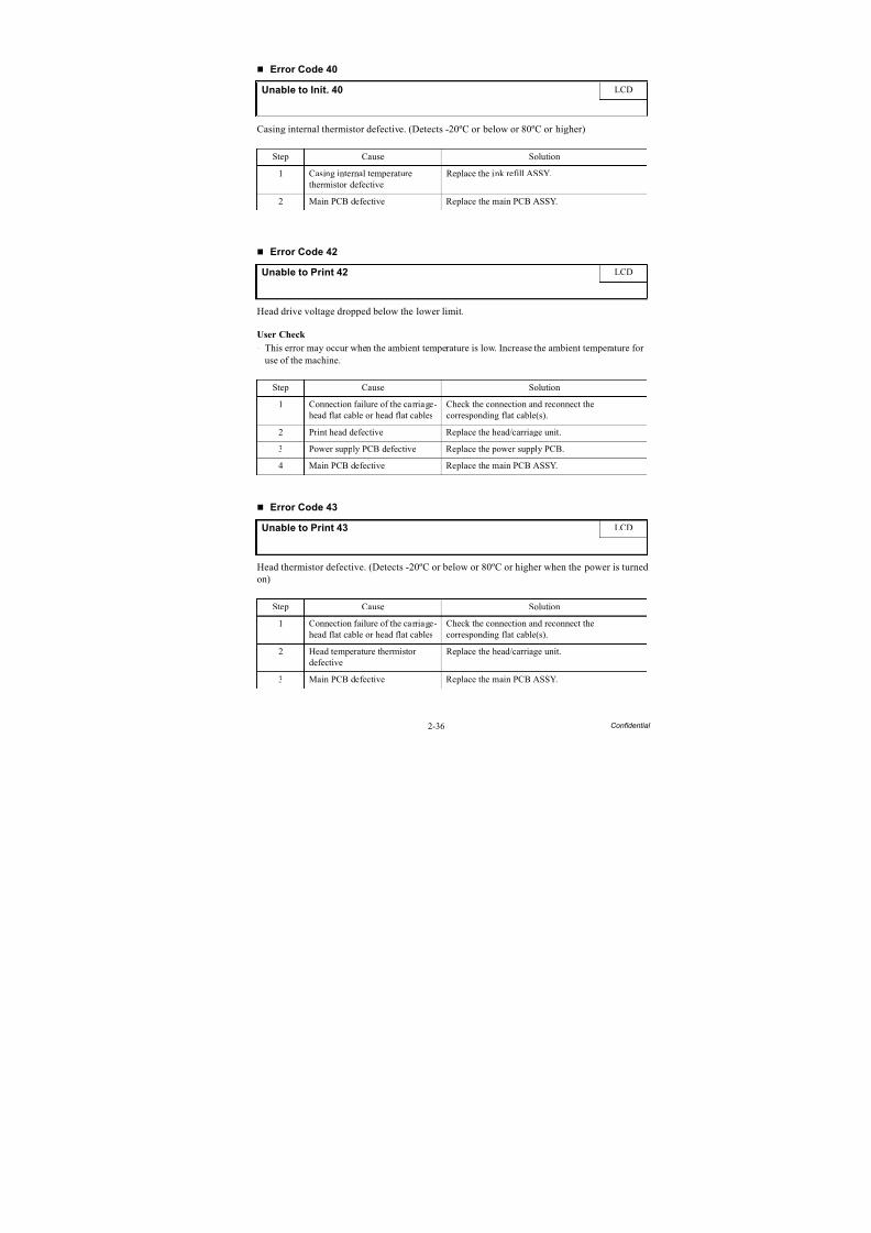
8/15/2019 Brother MFC 6510dw Sm
http://slidepdf.com/reader/full/brother-mfc-6510dw-sm 66/392
2-36 Confidential
Error Code 40
Casing internal thermistor defective. (Detects -20ºC or below or 80ºC or higher)
Error Code 42
Head drive voltage dropped below the lower limit.
User Check
- This error may occur when the ambient temperature is low. Increase the ambient temperature foruse of the machine.
Error Code 43
Head thermistor defective. (Detects -20ºC or below or 80ºC or higher when the power is turnedon)
Unable to Init. 40 LCD
Step Cause Solution
1 Casing internal temperaturethermistor defective
Replace the ink refill ASSY.
2 Main PCB defective Replace the main PCB ASSY.
Unable to Print 42 LCD
Step Cause Solution
1 Connection failure of the carriage-
head flat cable or head flat cables
Check the connection and reconnect the
corresponding flat cable(s).
2 Print head defective Replace the head/carriage unit.
3 Power supply PCB defective Replace the power supply PCB.
4 Main PCB defective Replace the main PCB ASSY.
Unable to Print 43 LCD
Step Cause Solution
1 Connection failure of the carriage-head flat cable or head flat cables
Check the connection and reconnect thecorresponding flat cable(s).
2 Head temperature thermistordefective
Replace the head/carriage unit.
3 Main PCB defective Replace the main PCB ASSY.
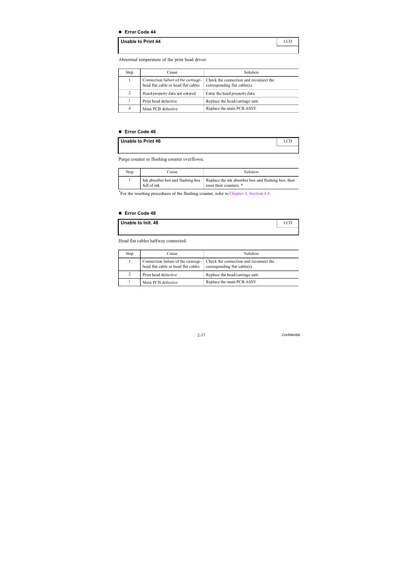
8/15/2019 Brother MFC 6510dw Sm
http://slidepdf.com/reader/full/brother-mfc-6510dw-sm 67/392
2-37 Confidential
Error Code 44
Abnormal temperature of the print head driver.
Error Code 46
Purge counter or flushing counter overflown.
*For the resetting procedures of the flushing counter, refer to Chapter 4, Section 4.4.
Error Code 48
Head flat cables halfway connected.
Unable to Print 44 LCD
Step Cause Solution
1 Connection failure of the carriage-head flat cable or head flat cables
Check the connection and reconnect thecorresponding flat cable(s).
2 Head property data not entered Enter the head property data.
3 Print head defective Replace the head/carriage unit.
4 Main PCB defective Replace the main PCB ASSY.
Unable to Print 46 LCD
Step Cause Solution
1 Ink absorber box and flushing boxfull of ink
Replace the ink absorber box and flushing box, thenreset their counters. *
Unable to Init. 48 LCD
Step Cause Solution1 Connection failure of the carriage-
head flat cable or head flat cablesCheck the connection and reconnect thecorresponding flat cable(s).
2 Print head defective Replace the head/carriage unit.
3 Main PCB defective Replace the main PCB ASSY.
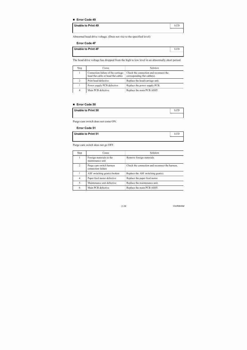
8/15/2019 Brother MFC 6510dw Sm
http://slidepdf.com/reader/full/brother-mfc-6510dw-sm 68/392
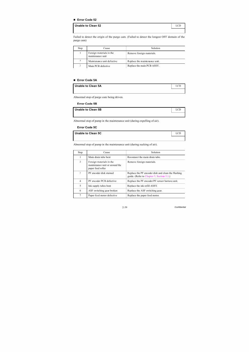
8/15/2019 Brother MFC 6510dw Sm
http://slidepdf.com/reader/full/brother-mfc-6510dw-sm 69/392
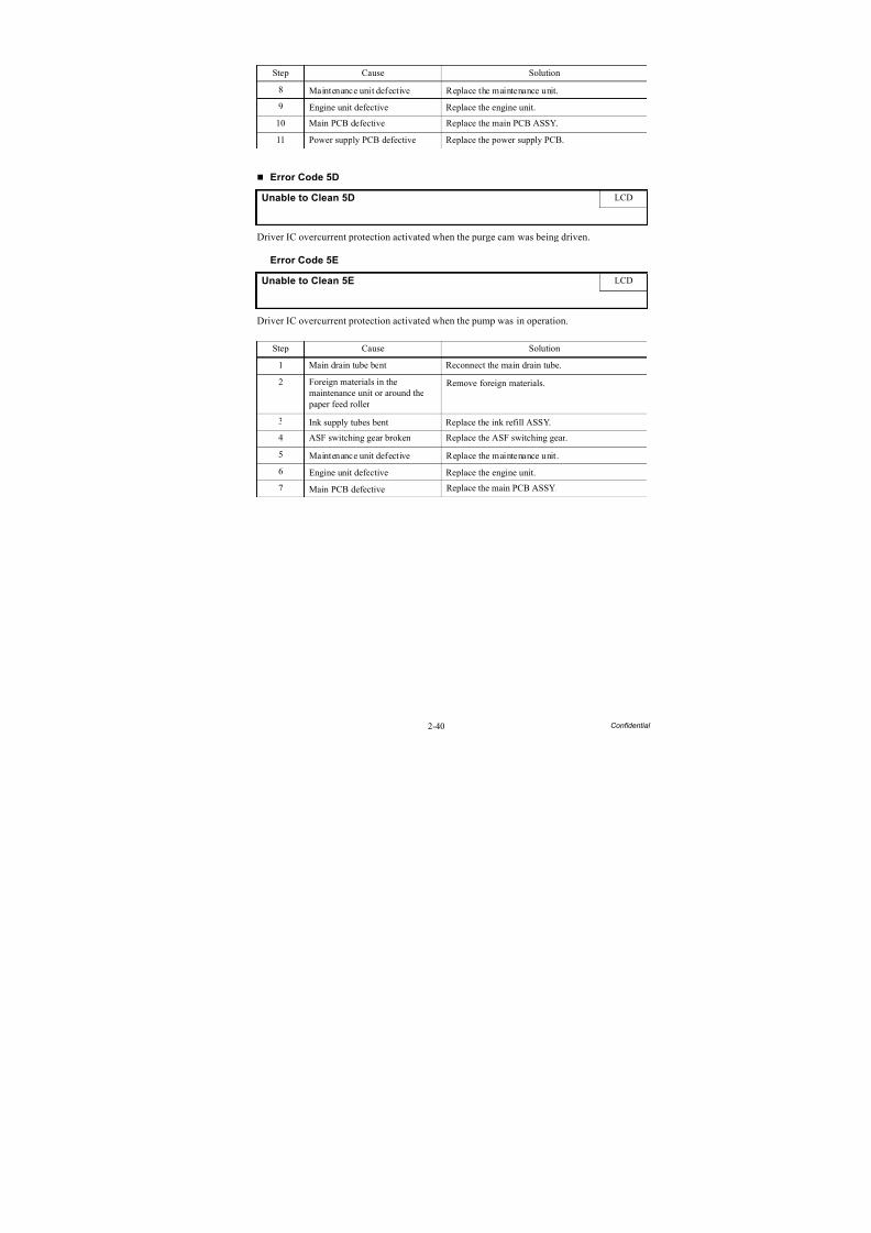
8/15/2019 Brother MFC 6510dw Sm
http://slidepdf.com/reader/full/brother-mfc-6510dw-sm 70/392
2-40 Confidential
Error Code 5D
Driver IC overcurrent protection activated when the purge cam was being driven.
Error Code 5E
Driver IC overcurrent protection activated when the pump was in operation.
Step Cause Solution
8 Maintenance unit defective Replace the maintenance unit.
9 Engine unit defective Replace the engine unit.
10 Main PCB defective Replace the main PCB ASSY.
11 Power supply PCB defective Replace the power supply PCB.
Unable to Clean 5D LCD
Unable to Clean 5E LCD
Step Cause Solution
1 Main drain tube bent Reconnect the main drain tube.
2 Foreign materials in themaintenance unit or around the
paper feed roller
Remove foreign materials.
3 Ink supply tubes bent Replace the ink refill ASSY.
4 ASF switching gear broken Replace the ASF switching gear.
5 Maintenance unit defective Replace the maintenance unit.
6 Engine unit defective Replace the engine unit.
7 Main PCB defective Replace the main PCB ASSY.
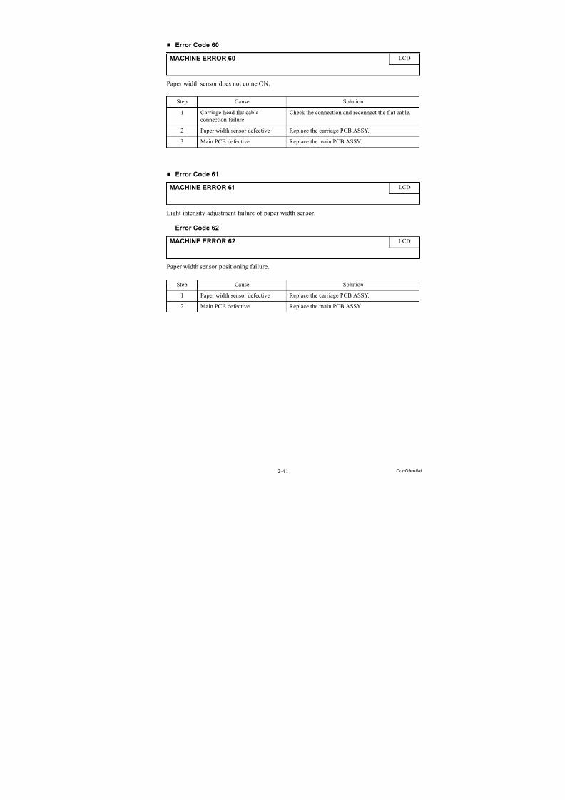
8/15/2019 Brother MFC 6510dw Sm
http://slidepdf.com/reader/full/brother-mfc-6510dw-sm 71/392
2-41 Confidential
Error Code 60
Paper width sensor does not come ON.
Error Code 61
Light intensity adjustment failure of paper width sensor.
Error Code 62
Paper width sensor positioning failure.
MACHINE ERROR 60 LCD
Step Cause Solution
1 Carriage-head flat cableconnection failure
Check the connection and reconnect the flat cable.
2 Paper width sensor defective Replace the carriage PCB ASSY.
3 Main PCB defective Replace the main PCB ASSY.
MACHINE ERROR 61 LCD
MACHINE ERROR 62 LCD
Step Cause Solution
1 Paper width sensor defective Replace the carriage PCB ASSY.
2 Main PCB defective Replace the main PCB ASSY.
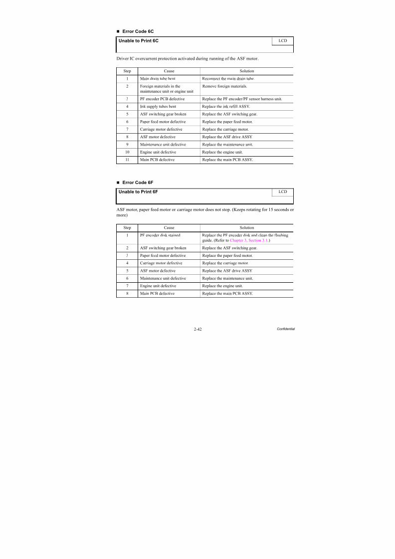
8/15/2019 Brother MFC 6510dw Sm
http://slidepdf.com/reader/full/brother-mfc-6510dw-sm 72/392
2-42 Confidential
Error Code 6C
Driver IC overcurrent protection activated during running of the ASF motor.
Error Code 6F
ASF motor, paper feed motor or carriage motor does not stop. (Keeps rotating for 15 seconds or more)
Unable to Print 6C LCD
Step Cause Solution
1 Main drain tube bent Reconnect the main drain tube.
2 Foreign materials in themaintenance unit or engine unit
Remove foreign materials.
3 PF encoder PCB defective Replace the PF encoder/PF sensor harness unit.
4 Ink supply tubes bent Replace the ink refill ASSY.
5 ASF switching gear broken Replace the ASF switching gear.
6 Paper feed motor defective Replace the paper feed motor.
7 Carriage motor defective Replace the carriage motor.
8 ASF motor defective Replace the ASF drive ASSY.
9 Maintenance unit defective Replace the maintenance unit.
10 Engine unit defective Replace the engine unit.
11 Main PCB defective Replace the main PCB ASSY.
Unable to Print 6F LCD
Step Cause Solution
1 PF encoder disk stained Replace the PF encoder disk and clean the flushingguide. (Refer to Chapter 3, Section 3.1.)
2 ASF switching gear broken Replace the ASF switching gear.
3 Paper feed motor defective Replace the paper feed motor.
4 Carriage motor defective Replace the carriage motor.
5 ASF motor defective Replace the ASF drive ASSY.
6 Maintenance unit defective Replace the maintenance unit.
7 Engine unit defective Replace the engine unit.
8 Main PCB defective Replace the main PCB ASSY.
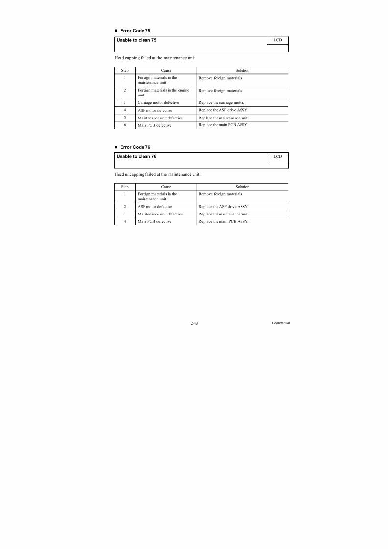
8/15/2019 Brother MFC 6510dw Sm
http://slidepdf.com/reader/full/brother-mfc-6510dw-sm 73/392
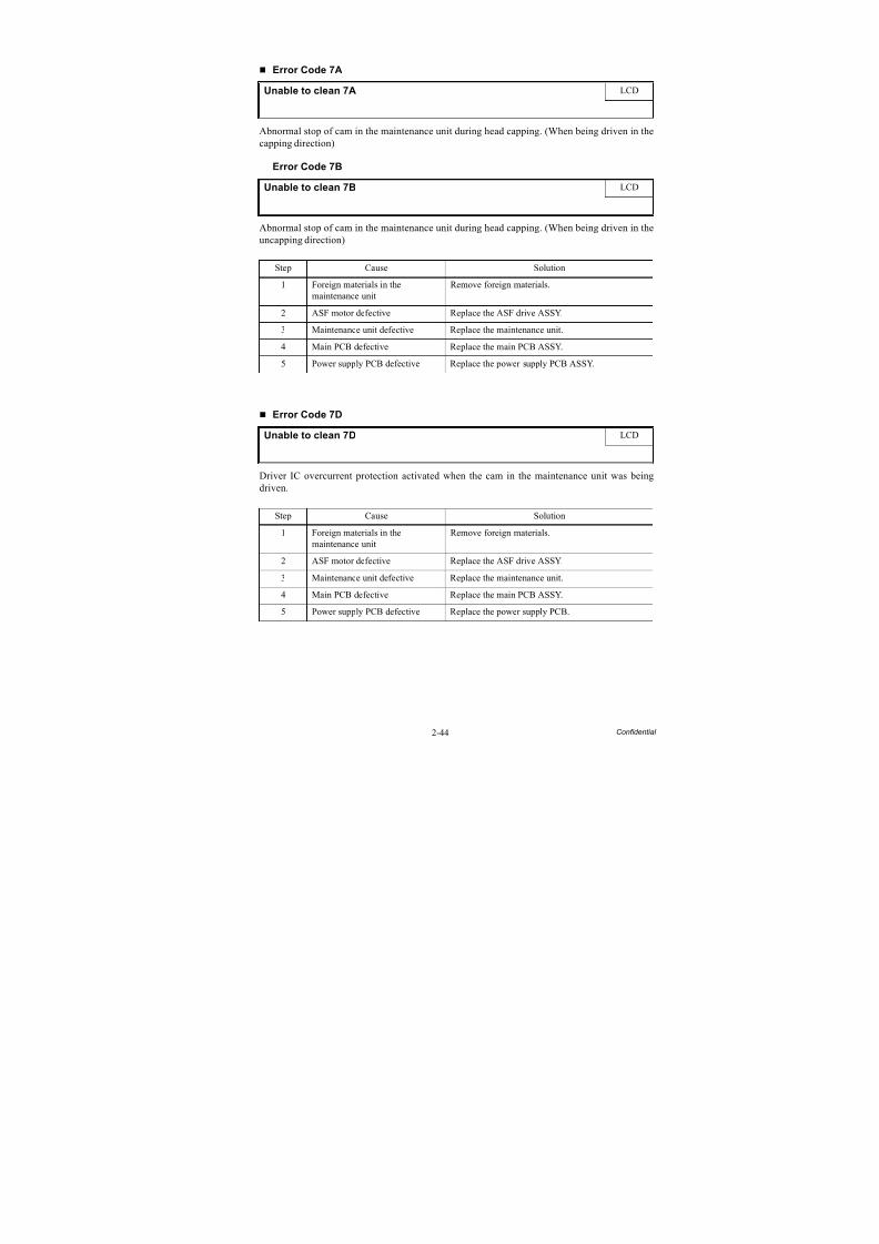
8/15/2019 Brother MFC 6510dw Sm
http://slidepdf.com/reader/full/brother-mfc-6510dw-sm 74/392
2-44 Confidential
Error Code 7A
Abnormal stop of cam in the maintenance unit during head capping. (When being driven in the
capping direction)
Error Code 7B
Abnormal stop of cam in the maintenance unit during head capping. (When being driven in theuncapping direction)
Error Code 7D
Driver IC overcurrent protection activated when the cam in the maintenance unit was beingdriven.
Unable to clean 7A LCD
Unable to clean 7B LCD
Step Cause Solution
1 Foreign materials in themaintenance unit
Remove foreign materials.
2 ASF motor defective Replace the ASF drive ASSY.
3 Maintenance unit defective Replace the maintenance unit.
4 Main PCB defective Replace the main PCB ASSY.
5 Power supply PCB defective Replace the power supply PCB ASSY.
Unable to clean 7D LCD
Step Cause Solution
1 Foreign materials in themaintenance unit
Remove foreign materials.
2 ASF motor defective Replace the ASF drive ASSY.
3 Maintenance unit defective Replace the maintenance unit.
4 Main PCB defective Replace the main PCB ASSY.
5 Power supply PCB defective Replace the power supply PCB.
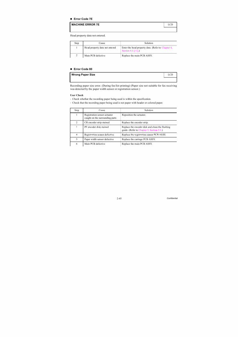
8/15/2019 Brother MFC 6510dw Sm
http://slidepdf.com/reader/full/brother-mfc-6510dw-sm 75/392
2-45 Confidential
Error Code 7E
Head property data not entered.
Error Code 80
Recording paper size error. (During fax/list printing) (Paper size not suitable for fax receivingwas detected by the paper width sensor or registration sensor.)
User Check
- Check whether the recording paper being used is within the specification.
- Check that the recording paper being used is not paper with header or colored paper.
MACHINE ERROR 7E LCD
Step Cause Solution
1 Head property data not entered Enter the head property data. (Refer to Chapter 4,Section 4.1 [ 1 ].)
2 Main PCB defective Replace the main PCB ASSY.
Wrong Paper Size LCD
Step Cause Solution
1 Registration sensor actuatorcaught on the surrounding parts
Reposition the actuator.
2 CR encoder strip stained Replace the encoder strip.
3 PF encoder disk stained Replace the encoder disk and clean the flushingguide. (Refer to Chapter 3, Section 3.1.)
4 Registration sensor defective Replace the registration sensor PCB ASSY.
5 Paper width sensor defective Replace the carriage PCB ASSY.
6 Main PCB defective Replace the main PCB ASSY.
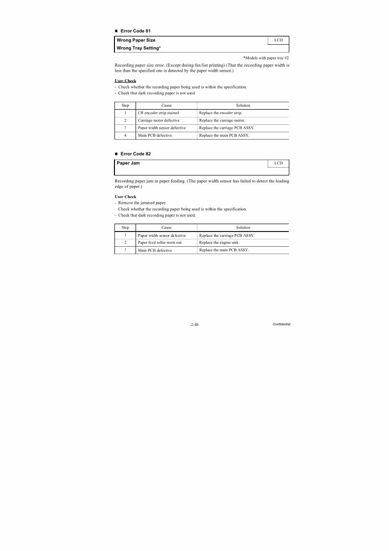
8/15/2019 Brother MFC 6510dw Sm
http://slidepdf.com/reader/full/brother-mfc-6510dw-sm 76/392
2-46 Confidential
Error Code 81
*Models with paper tray #2
Recording paper size error. (Except during fax/list printing) (That the recording paper width isless than the specified one is detected by the paper width sensor.)
User Check
- Check whether the recording paper being used is within the specification.
- Check that dark recording paper is not used.
Error Code 82
Recording paper jam in paper feeding. (The paper width sensor has failed to detect the leading
edge of paper.)
User Check
- Remove the jammed paper.
- Check whether the recording paper being used is within the specification.
- Check that dark recording paper is not used.
Wrong Paper Size LCD
Wrong Tray Setting*
Step Cause Solution
1 CR encoder strip stained Replace the encoder strip.
2 Carriage motor defective Replace the carriage motor.
3 Paper width sensor defective Replace the carriage PCB ASSY.
4 Main PCB defective Replace the main PCB ASSY.
Paper Jam LCD
Step Cause Solution
1 Paper width sensor defective Replace the carriage PCB ASSY.
2 Paper feed roller worn out Replace the engine unit.
3 Main PCB defective Replace the main PCB ASSY.
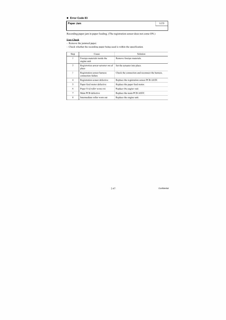
8/15/2019 Brother MFC 6510dw Sm
http://slidepdf.com/reader/full/brother-mfc-6510dw-sm 77/392
2-47 Confidential
Error Code 83
Recording paper jam in paper feeding. (The registration sensor does not come ON.)
User Check
- Remove the jammed paper.
- Check whether the recording paper being used is within the specification.
Paper Jam LCD
Step Cause Solution
1 Foreign materials inside theengine unit
Remove foreign materials.
2 Registration sensor actuator out of place
Set the actuator into place.
3 Registration sensor harnessconnection failure
Check the connection and reconnect the harness.
4 Registration sensor defective Replace the registration sensor PCB ASSY.
5 Paper feed motor defective Replace the paper feed motor.
6 Paper feed roller worn out Replace the engine unit.
7 Main PCB defective Replace the main PCB ASSY.
8 Intermediate roller worn out Replace the engine unit.
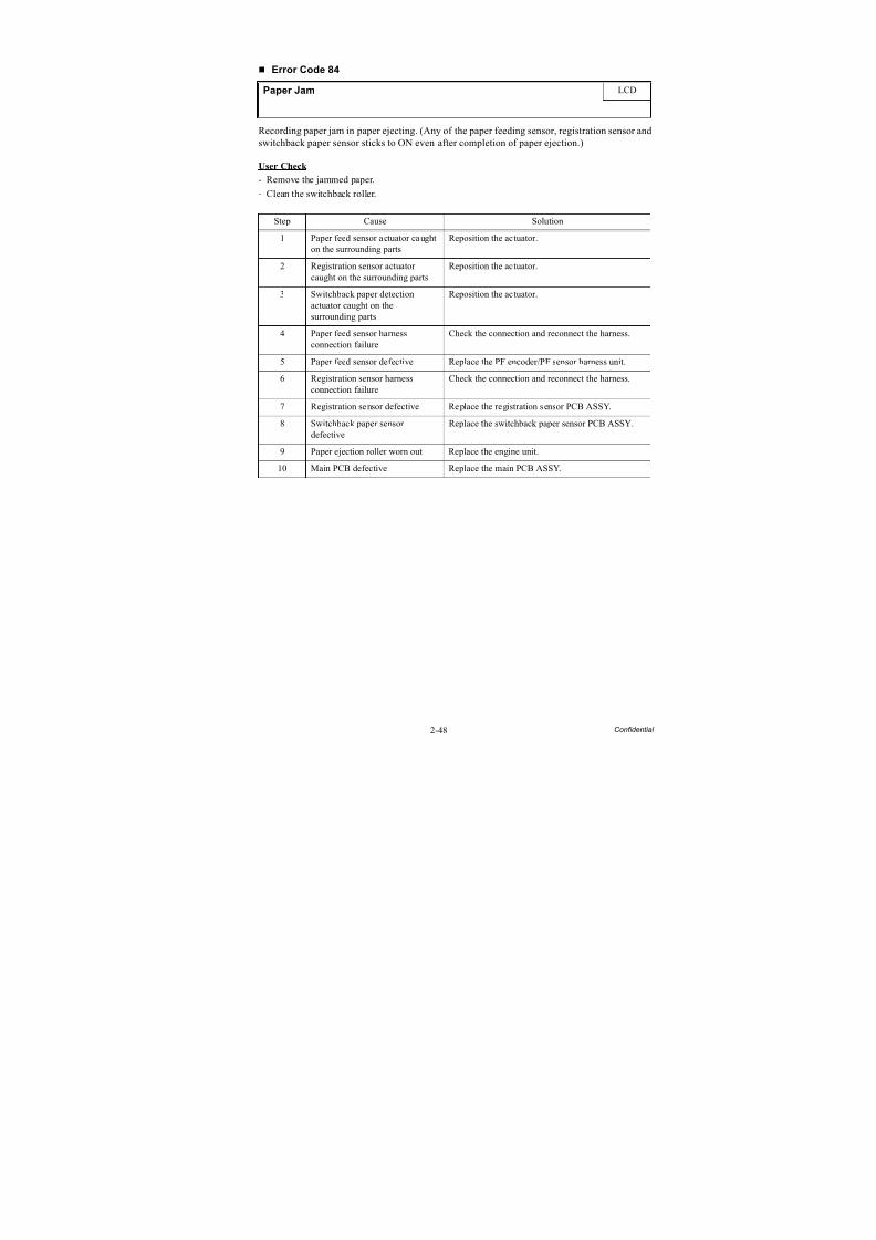
8/15/2019 Brother MFC 6510dw Sm
http://slidepdf.com/reader/full/brother-mfc-6510dw-sm 78/392
2-48 Confidential
Error Code 84
Recording paper jam in paper ejecting. (Any of the paper feeding sensor, registration sensor and
switchback paper sensor sticks to ON even after completion of paper ejection.)
User Check
- Remove the jammed paper.
- Clean the switchback roller.
Paper Jam LCD
Step Cause Solution
1 Paper feed sensor actuator caughton the surrounding parts
Reposition the actuator.
2 Registration sensor actuator
caught on the surrounding parts
Reposition the actuator.
3 Switchback paper detectionactuator caught on thesurrounding parts
Reposition the actuator.
4 Paper feed sensor harnessconnection failure
Check the connection and reconnect the harness.
5 Paper feed sensor defective Replace the PF encoder/PF sensor harness unit.
6 Registration sensor harnessconnection failure
Check the connection and reconnect the harness.
7 Registration sensor defective Replace the registration sensor PCB ASSY.
8 Switchback paper sensordefective
Replace the switchback paper sensor PCB ASSY.
9 Paper ejection roller worn out Replace the engine unit.
10 Main PCB defective Replace the main PCB ASSY.
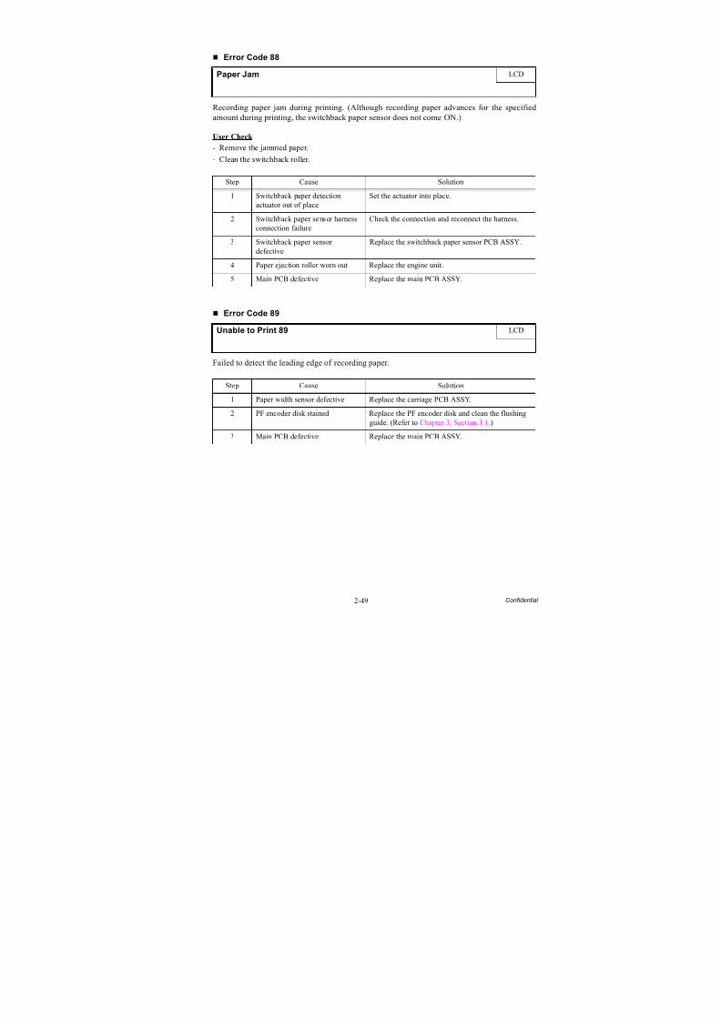
8/15/2019 Brother MFC 6510dw Sm
http://slidepdf.com/reader/full/brother-mfc-6510dw-sm 79/392
2-49 Confidential
Error Code 88
Recording paper jam during printing. (Although recording paper advances for the specified
amount during printing, the switchback paper sensor does not come ON.)
User Check
- Remove the jammed paper.
- Clean the switchback roller.
Error Code 89
Failed to detect the leading edge of recording paper.
Paper Jam LCD
Step Cause Solution
1 Switchback paper detectionactuator out of place
Set the actuator into place.
2 Switchback paper sensor harness
connection failure
Check the connection and reconnect the harness.
3 Switchback paper sensordefective
Replace the switchback paper sensor PCB ASSY.
4 Paper ejection roller worn out Replace the engine unit.
5 Main PCB defective Replace the main PCB ASSY.
Unable to Print 89 LCD
Step Cause Solution
1 Paper width sensor defective Replace the carriage PCB ASSY.
2 PF encoder disk stained Replace the PF encoder disk and clean the flushingguide. (Refer to Chapter 3, Section 3.1.)
3 Main PCB defective Replace the main PCB ASSY.
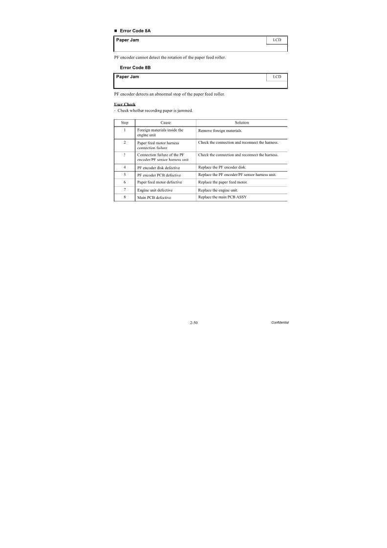
8/15/2019 Brother MFC 6510dw Sm
http://slidepdf.com/reader/full/brother-mfc-6510dw-sm 80/392
2-50 Confidential
Error Code 8A
PF encoder cannot detect the rotation of the paper feed roller.
Error Code 8B
PF encoder detects an abnormal stop of the paper feed roller.
User Check
- Check whether recording paper is jammed.
Paper Jam LCD
Paper Jam LCD
Step Cause Solution1 Foreign materials inside the
engine unitRemove foreign materials.
2 Paper feed motor harnessconnection failure
Check the connection and reconnect the harness.
3 Connection failure of the PFencoder/PF sensor harness unit
Check the connection and reconnect the harness.
4 PF encoder disk defective Replace the PF encoder disk.
5 PF encoder PCB defective Replace the PF encoder/PF sensor harness unit.
6 Paper feed motor defective Replace the paper feed motor.
7 Engine unit defective Replace the engine unit.
8 Main PCB defective Replace the main PCB ASSY.
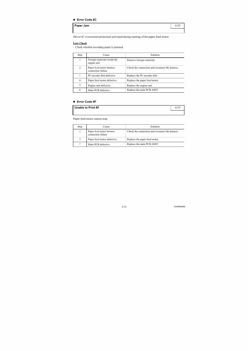
8/15/2019 Brother MFC 6510dw Sm
http://slidepdf.com/reader/full/brother-mfc-6510dw-sm 81/392
2-51 Confidential
Error Code 8C
Driver IC overcurrent protection activated during running of the paper feed motor.
User Check
- Check whether recording paper is jammed.
Error Code 8F
Paper feed motor cannot stop.
Paper Jam LCD
Step Cause Solution
1 Foreign materials inside theengine unit
Remove foreign materials.
2 Paper feed motor harnessconnection failure
Check the connection and reconnect the harness.
3 PF encoder disk defective Replace the PF encoder disk.
4 Paper feed motor defective Replace the paper feed motor.
5 Engine unit defective Replace the engine unit.
6 Main PCB defective Replace the main PCB ASSY.
Unable to Print 8F LCD
Step Cause Solution
1 Paper feed motor harnessconnection failure
Check the connection and reconnect the harness.
2 Paper feed motor defective Replace the paper feed motor.
3 Main PCB defective Replace the main PCB ASSY.
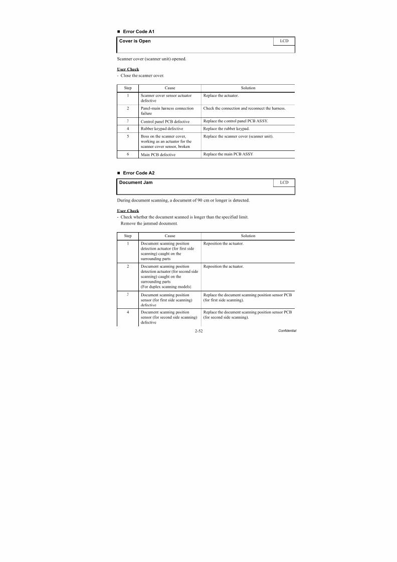
8/15/2019 Brother MFC 6510dw Sm
http://slidepdf.com/reader/full/brother-mfc-6510dw-sm 82/392
2-52 Confidential
Error Code A1
Scanner cover (scanner unit) opened.
User Check
- Close the scanner cover.
Error Code A2
During document scanning, a document of 90 cm or longer is detected.
User Check
- Check whether the document scanned is longer than the specified limit.
- Remove the jammed document.
Cover is Open LCD
Step Cause Solution
1 Scanner cover sensor actuatordefective
Replace the actuator.
2 Panel-main harness connectionfailure
Check the connection and reconnect the harness.
3 Control panel PCB defective Replace the control panel PCB ASSY.
4 Rubber keypad defective Replace the rubber keypad.
5 Boss on the scanner cover,working as an actuator for thescanner cover sensor, broken
Replace the scanner cover (scanner unit).
6 Main PCB defective Replace the main PCB ASSY.
Document Jam LCD
Step Cause Solution
1 Document scanning positiondetection actuator (for first side
scanning) caught on thesurrounding parts
Reposition the actuator.
2 Document scanning positiondetection actuator (for second sidescanning) caught on thesurrounding parts(For duplex scanning models)
Reposition the actuator.
3 Document scanning positionsensor (for first side scanning)defective
Replace the document scanning position sensor PCB(for first side scanning).
4 Document scanning positionsensor (for second side scanning)defective
Replace the document scanning position sensor PCB(for second side scanning).
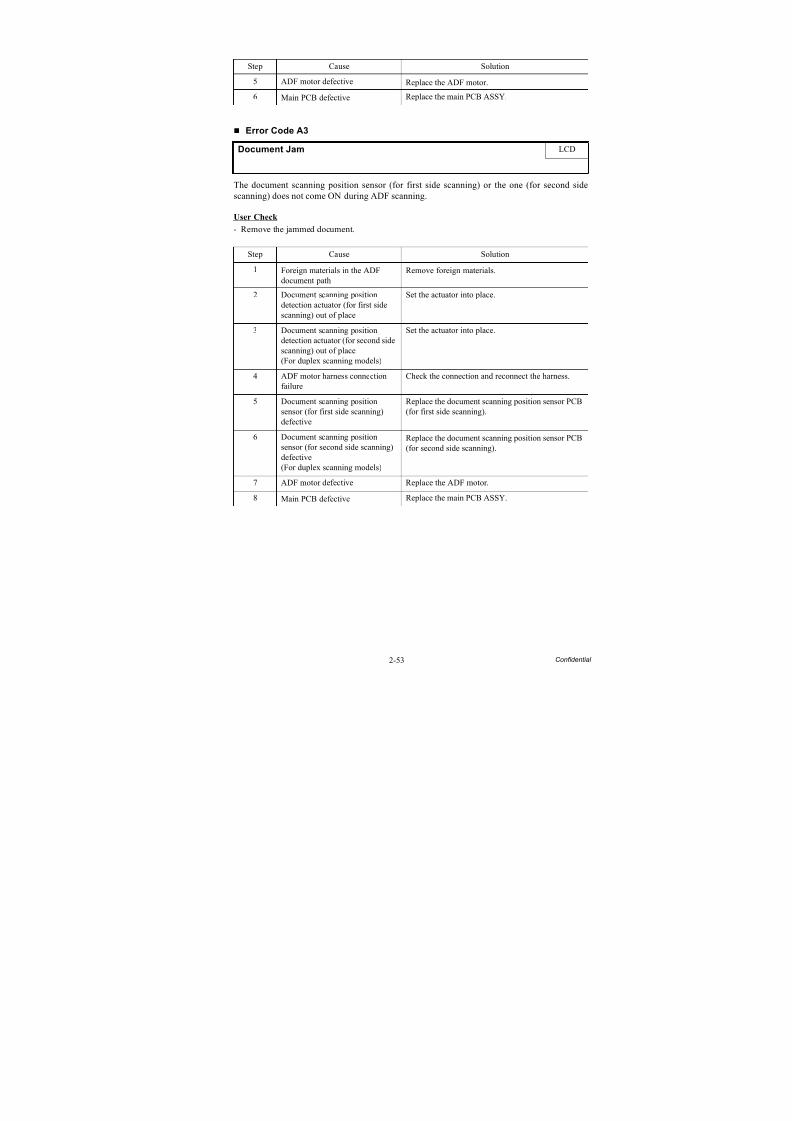
8/15/2019 Brother MFC 6510dw Sm
http://slidepdf.com/reader/full/brother-mfc-6510dw-sm 83/392
2-53 Confidential
Error Code A3
The document scanning position sensor (for first side scanning) or the one (for second sidescanning) does not come ON during ADF scanning.
User Check
- Remove the jammed document.
Step Cause Solution
5 ADF motor defective Replace the ADF motor.
6 Main PCB defective Replace the main PCB ASSY.
Document Jam LCD
Step Cause Solution
1 Foreign materials in the ADFdocument path
Remove foreign materials.
2 Document scanning positiondetection actuator (for first sidescanning) out of place
Set the actuator into place.
3 Document scanning positiondetection actuator (for second sidescanning) out of place(For duplex scanning models)
Set the actuator into place.
4 ADF motor harness connectionfailure
Check the connection and reconnect the harness.
5 Document scanning positionsensor (for first side scanning)defective
Replace the document scanning position sensor PCB(for first side scanning).
6 Document scanning positionsensor (for second side scanning)defective(For duplex scanning models)
Replace the document scanning position sensor PCB(for second side scanning).
7 ADF motor defective Replace the ADF motor.
8Main PCB defective
Replace the main PCB ASSY.
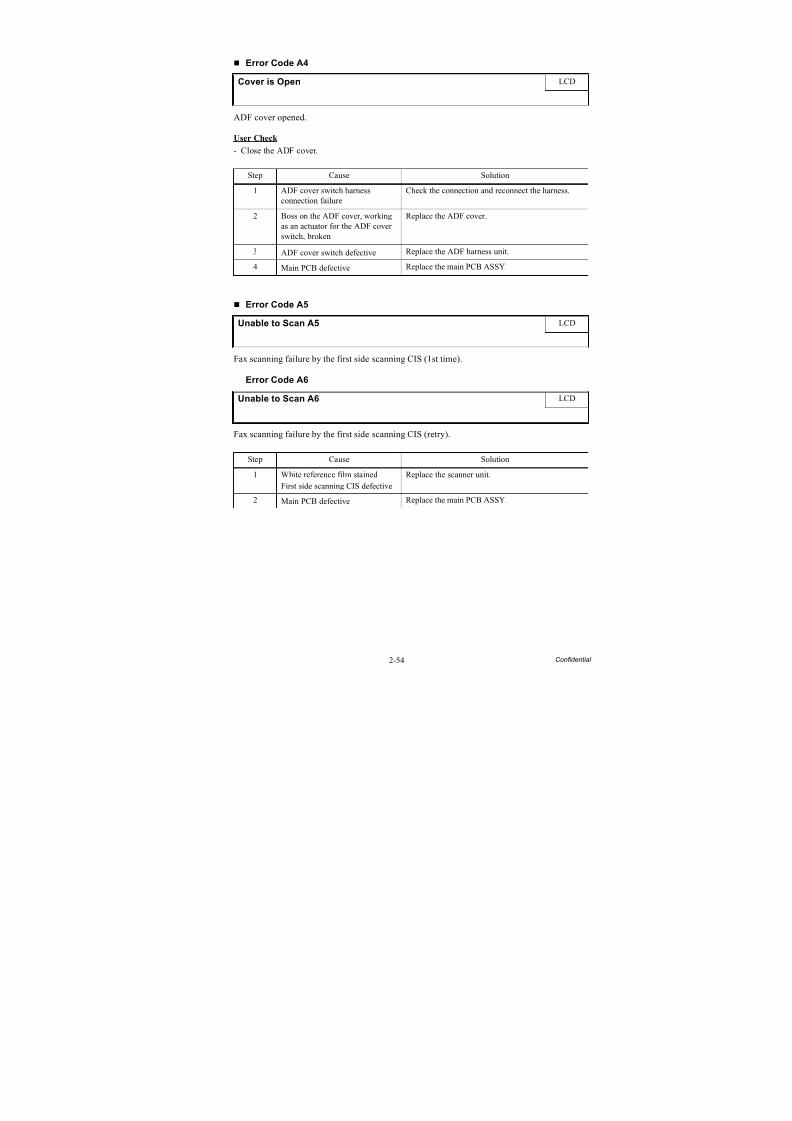
8/15/2019 Brother MFC 6510dw Sm
http://slidepdf.com/reader/full/brother-mfc-6510dw-sm 84/392
2-54 Confidential
Error Code A4
ADF cover opened.
User Check
- Close the ADF cover.
Error Code A5
Fax scanning failure by the first side scanning CIS (1st time).
Error Code A6
Fax scanning failure by the first side scanning CIS (retry).
Cover is Open LCD
Step Cause Solution
1 ADF cover switch harnessconnection failure
Check the connection and reconnect the harness.
2 Boss on the ADF cover, workingas an actuator for the ADF coverswitch, broken
Replace the ADF cover.
3 ADF cover switch defective Replace the ADF harness unit.4 Main PCB defective Replace the main PCB ASSY.
Unable to Scan A5 LCD
Unable to Scan A6 LCD
Step Cause Solution
1 White reference film stained
First side scanning CIS defective
Replace the scanner unit.
2 Main PCB defective Replace the main PCB ASSY.
8/15/2019 Brother MFC 6510dw Sm
http://slidepdf.com/reader/full/brother-mfc-6510dw-sm 85/392
2-55 Confidential
Error Code A7
Mismatch between actual CIS type and EEPROM data.
Error Code A8
Color parameter matching error. (Used for monitoring bugs at the factory.)
Error Code AC
Fax scanning failure by the second side scanning CIS (1st time).
User Check
- Send a fax again.
Unable to Scan A7 LCD
Step Cause Solution
1 Main PCB defective Replace the main PCB ASSY.
Unable to Init. A8 LCD
Step Cause Solution
1 Program malfunctioning Reload programs.
2 Main PCB defective Replace the main PCB ASSY.
Unable to Scan AC LCD
Step Cause Solution
1 Document pressure bar (forsecond side scanning) stained
Clean the document pressure bar.
2 Second side scanning CISdefective
Replace the CIS unit.
3 Main PCB defective Replace the main PCB ASSY.
8/15/2019 Brother MFC 6510dw Sm
http://slidepdf.com/reader/full/brother-mfc-6510dw-sm 86/392
2-56 Confidential
Error Code AF
Positioning error of the first side scanning CIS. (Home positioning failed)
Error Code BC
Fax scanning failure by the second side scanning CIS (retry).
Error Code BD
Black level data error in scanning.
Unable to Scan AF LCD
Step Cause Solution
1 Connection failure of the CISmotor harness of the scanner unit
Check the connection and reconnect the harness.
2 Scanner unit defective Replace the scanner unit.
3 Main PCB defective Replace the main PCB ASSY.
Unable to Scan BC LCD
Step Cause Solution
1 Document pressure bar (forsecond side scanning) stained
Clean the document pressure bar.
2 Second side scanning CIS
defective
Replace the CIS unit.
3 Main PCB defective Replace the main PCB ASSY.
Unable to Scan BD LCD
Step Cause Solution
1 Black reference film stained Replace the scanner unit.
2 Main PCB defective Replace the main PCB ASSY.
8/15/2019 Brother MFC 6510dw Sm
http://slidepdf.com/reader/full/brother-mfc-6510dw-sm 87/392
2-57 Confidential
Error Code BF
During the second side scanning in the ADF, a document longer than the specified limit is
detected.
User Check
- Check whether the document scanned is longer than the specified limit.
Error Code DF
SDAA failure.
Error Code E0
Modem cannot start up normally even after reset.
Document Jam / Too long LCD
Step Cause Solution
1 Document scanning positiondetection actuator (for second sidescanning) caught on thesurrounding parts
Reposition the actuator.
2 Connection failure of thedocument scanning positionsensor harness (for second sidescanning)
Check the connection and reconnect the harness.
3 Document scanning positionsensor (for second side scanning)defective
Replace the document scanning position sensor PCB(for second side scanning).
4 ADF motor defective Replace the ADF motor.
5 Main PCB defective Replace the main PCB ASSY.
Unable to Init. DF LCD
Unable to Init. E0 LCD
Step Cause Solution
1 Main PCB defective Replace the main PCB ASSY.
8/15/2019 Brother MFC 6510dw Sm
http://slidepdf.com/reader/full/brother-mfc-6510dw-sm 88/392
2-58 Confidential
Error Code E2
Wired MAC address not registered.
Error Code E3
Wireless MAC address not registered.
User Check
Enter the wired/wireless MAC address again.
Error Code E5
This error does not occur under normal use. It is considered to be caused by electrical noise inthe vicinity of the machine, power voltage fluctuation, or software failure.
Unidentifiable error.
User Check
- Unplug the power cord, wait a while, and plug the power cord again to turn the power ON.
Error Code E6
Write error in EEPROM.
MACHINE ERROR E2 LCD
MACHINE ERROR E3 LCD
Step Cause Solution1 Main PCB defective Replace the main PCB ASSY.
MACHINE ERROR E5 LCD
Step Cause Solution
1 Main PCB defective Replace the main PCB ASSY.
Unable to Init. E6 LCD
Step Cause Solution
1 Main PCB defective Replace the main PCB ASSY.
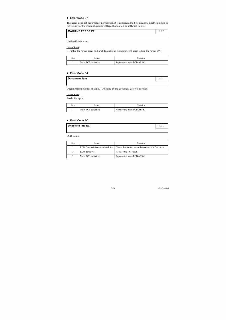
8/15/2019 Brother MFC 6510dw Sm
http://slidepdf.com/reader/full/brother-mfc-6510dw-sm 89/392
2-59 Confidential
Error Code E7
This error does not occur under normal use. It is considered to be caused by electrical noise inthe vicinity of the machine, power voltage fluctuation, or software failure.
Unidentifiable error.
User Check
- Unplug the power cord, wait a while, and plug the power cord again to turn the power ON.
Error Code EA
Document removed at phase B. (Detected by the document detection sensor)
User Check
Send a fax again.
Error Code EC
LCD failure.
MACHINE ERROR E7 LCD
Step Cause Solution
1 Main PCB defective Replace the main PCB ASSY.
Document Jam LCD
Step Cause Solution
1 Main PCB defective Replace the main PCB ASSY.
Unable to Init. EC LCD
Step Cause Solution1 LCD flat cable connection failure Check the connection and reconnect the flat cable.
2 LCD defective Replace the LCD unit.
3 Main PCB defective Replace the main PCB ASSY.
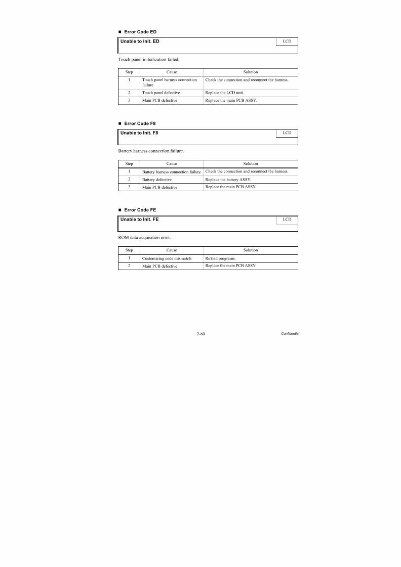
8/15/2019 Brother MFC 6510dw Sm
http://slidepdf.com/reader/full/brother-mfc-6510dw-sm 90/392
2-60 Confidential
Error Code ED
Touch panel initialization failed.
Error Code F8
Battery harness connection failure.
Error Code FE
ROM data acquisition error.
Unable to Init. ED LCD
Step Cause Solution
1 Touch panel harness connectionfailure
Check the connection and reconnect the harness.
2 Touch panel defective Replace the LCD unit.
3 Main PCB defective Replace the main PCB ASSY.
Unable to Init. F8 LCD
Step Cause Solution
1 Battery harness connection failure Check the connection and reconnect the harness.
2 Battery defective Replace the battery ASSY.
3 Main PCB defective Replace the main PCB ASSY.
Unable to Init. FE LCD
Step Cause Solution
1 Customizing code mismatch Reload programs.
2 Main PCB defective Replace the main PCB ASSY.
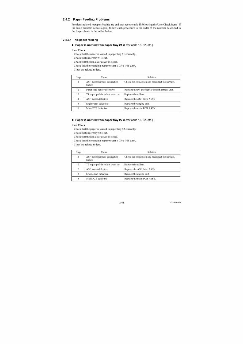
8/15/2019 Brother MFC 6510dw Sm
http://slidepdf.com/reader/full/brother-mfc-6510dw-sm 91/392
2-61 Confidential
2.4.2 Paper Feeding Problems
Problems related to paper feeding are end user recoverable if following the User Check items. If the same problem occurs again, follow each procedure in the order of the number described inthe Step column in the tables below.
2.4.2.1 No paper feeding
Paper is not fed from paper tray #1 (Error code 18, 82, etc.)
User Check
- Check that the paper is loaded in paper tray #1 correctly.
- Check that paper tray #1 is set.
- Check that the jam clear cover is closed.
- Check that the recording paper weight is 75 to 105 g/m2.
- Clean the related rollers.
Paper is not fed from paper tray #2 (Error code 18, 82, etc.)
User Check
- Check that the paper is loaded in paper tray #2 correctly.
- Check that paper tray #2 is set.
- Check that the jam clear cover is closed.
- Check that the recording paper weight is 75 to 105 g/m2.
- Clean the related rollers.
Step Cause Solution1 ASF motor harness connection
failureCheck the connection and reconnect the harness.
2 Paper feed sensor defective Replace the PF encoder/PF sensor harness unit.
3 T1 paper pull-in rollers worn out Replace the rollers.
4 ASF motor defective Replace the ASF drive ASSY.
5 Engine unit defective Replace the engine unit.
6 Main PCB defective Replace the main PCB ASSY.
Step Cause Solution
1 ASF motor harness connectionfailure
Check the connection and reconnect the harness.
2 T2 paper pull-in rollers worn out Replace the rollers.
3 ASF motor defective Replace the ASF drive ASSY.
4 Engine unit defective Replace the engine unit.
5 Main PCB defective Replace the main PCB ASSY.
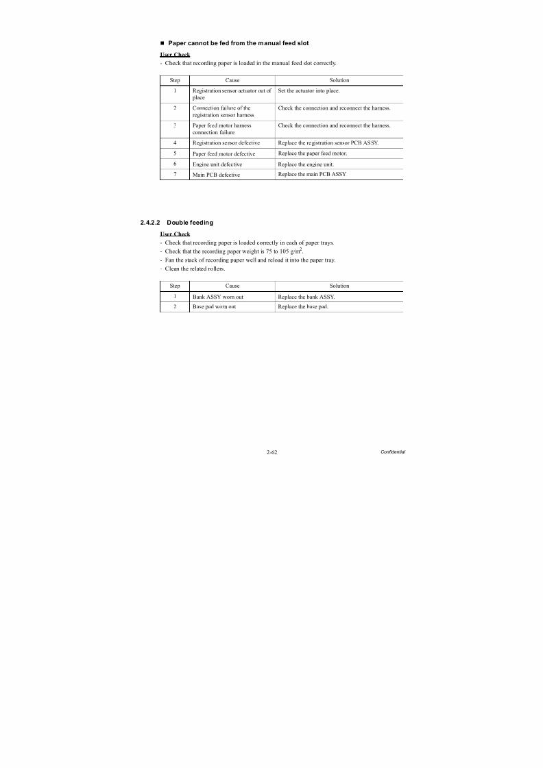
8/15/2019 Brother MFC 6510dw Sm
http://slidepdf.com/reader/full/brother-mfc-6510dw-sm 92/392
2-62 Confidential
Paper cannot be fed from the manual feed slot
User Check
- Check that recording paper is loaded in the manual feed slot correctly.
2.4.2.2 Double feeding
User Check
- Check that recording paper is loaded correctly in each of paper trays.
- Check that the recording paper weight is 75 to 105 g/m2.
- Fan the stack of recording paper well and reload it into the paper tray.- Clean the related rollers.
Step Cause Solution
1 Registration sensor actuator out of place
Set the actuator into place.
2 Connection failure of theregistration sensor harness
Check the connection and reconnect the harness.
3 Paper feed motor harnessconnection failure
Check the connection and reconnect the harness.
4 Registration sensor defective Replace the registration sensor PCB ASSY.
5 Paper feed motor defective Replace the paper feed motor.
6 Engine unit defective Replace the engine unit.
7 Main PCB defective Replace the main PCB ASSY.
Step Cause Solution
1 Bank ASSY worn out Replace the bank ASSY.
2 Base pad worn out Replace the base pad.
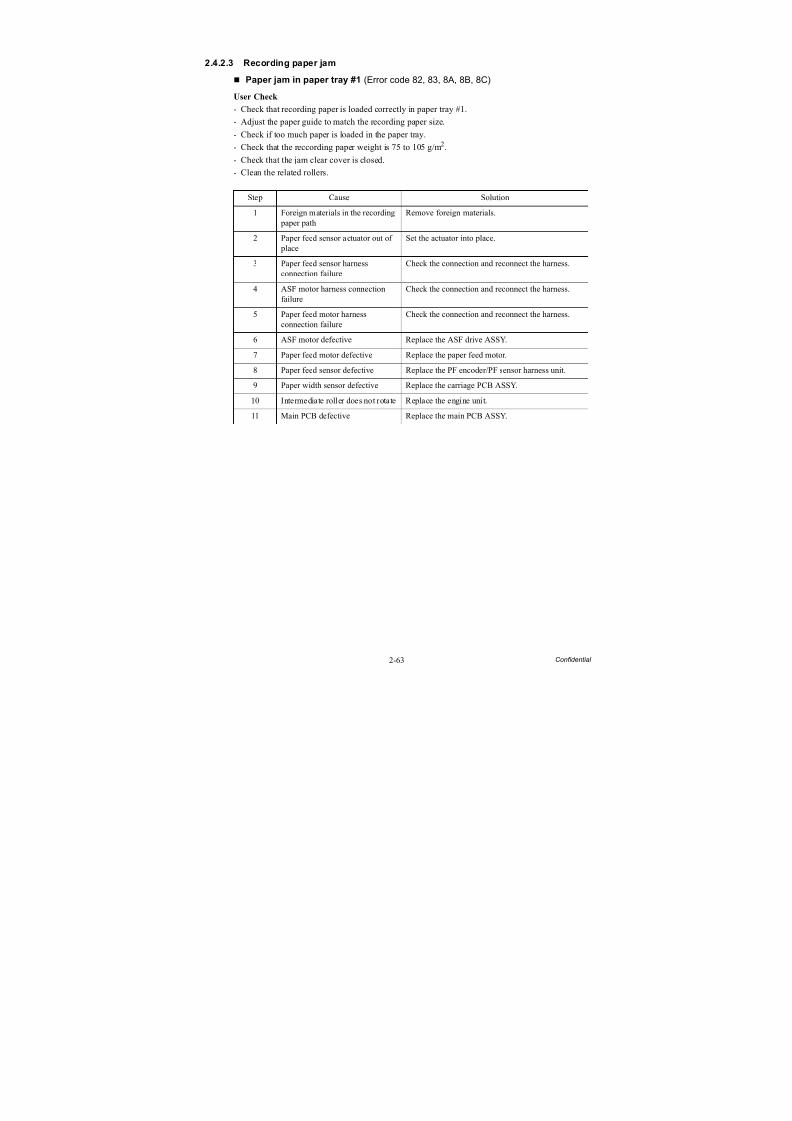
8/15/2019 Brother MFC 6510dw Sm
http://slidepdf.com/reader/full/brother-mfc-6510dw-sm 93/392
2-63 Confidential
2.4.2.3 Recording paper jam
Paper jam in paper tray #1 (Error code 82, 83, 8A, 8B, 8C)
User Check
- Check that recording paper is loaded correctly in paper tray #1.
- Adjust the paper guide to match the recording paper size.- Check if too much paper is loaded in the paper tray.
- Check that the reccording paper weight is 75 to 105 g/m2.
- Check that the jam clear cover is closed.
- Clean the related rollers.
Step Cause Solution
1 Foreign materials in the recording paper path
Remove foreign materials.
2 Paper feed sensor actuator out of
place
Set the actuator into place.
3 Paper feed sensor harnessconnection failure
Check the connection and reconnect the harness.
4 ASF motor harness connectionfailure
Check the connection and reconnect the harness.
5 Paper feed motor harnessconnection failure
Check the connection and reconnect the harness.
6 ASF motor defective Replace the ASF drive ASSY.
7 Paper feed motor defective Replace the paper feed motor.
8 Paper feed sensor defective Replace the PF encoder/PF sensor harness unit.
9 Paper width sensor defective Replace the carriage PCB ASSY.
10 Intermediate roller does not rotate Replace the engine unit.
11 Main PCB defective Replace the main PCB ASSY.
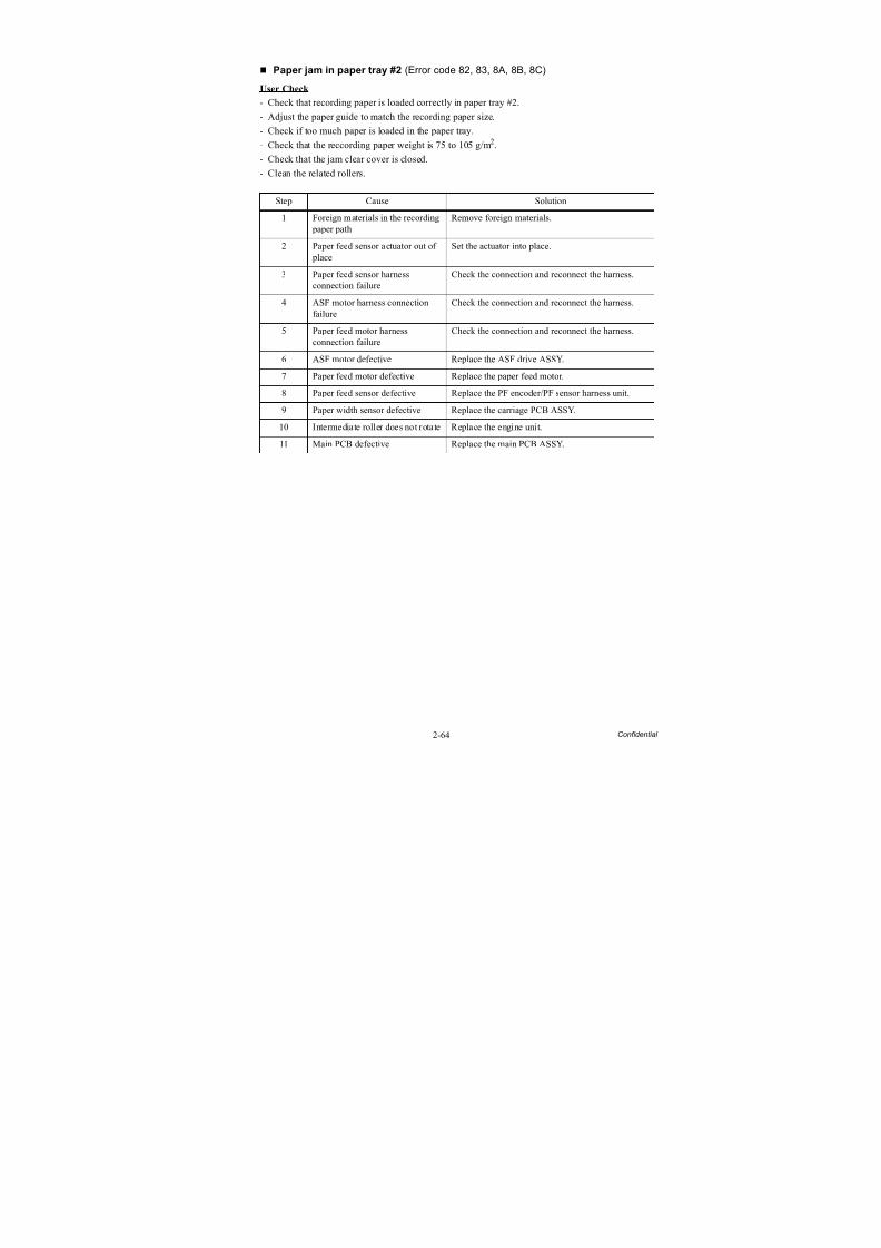
8/15/2019 Brother MFC 6510dw Sm
http://slidepdf.com/reader/full/brother-mfc-6510dw-sm 94/392
2-64 Confidential
Paper jam in paper tray #2 (Error code 82, 83, 8A, 8B, 8C)
User Check
- Check that recording paper is loaded correctly in paper tray #2.
- Adjust the paper guide to match the recording paper size.
- Check if too much paper is loaded in the paper tray.
- Check that the reccording paper weight is 75 to 105 g/m2.
- Check that the jam clear cover is closed.
- Clean the related rollers.
Step Cause Solution
1 Foreign materials in the recording paper path
Remove foreign materials.
2 Paper feed sensor actuator out of place
Set the actuator into place.
3 Paper feed sensor harnessconnection failure
Check the connection and reconnect the harness.
4 ASF motor harness connectionfailure
Check the connection and reconnect the harness.
5 Paper feed motor harnessconnection failure
Check the connection and reconnect the harness.
6 ASF motor defective Replace the ASF drive ASSY.
7 Paper feed motor defective Replace the paper feed motor.
8 Paper feed sensor defective Replace the PF encoder/PF sensor harness unit.
9 Paper width sensor defective Replace the carriage PCB ASSY.
10 Intermediate roller does not rotate Replace the engine unit.
11 Main PCB defective Replace the main PCB ASSY.
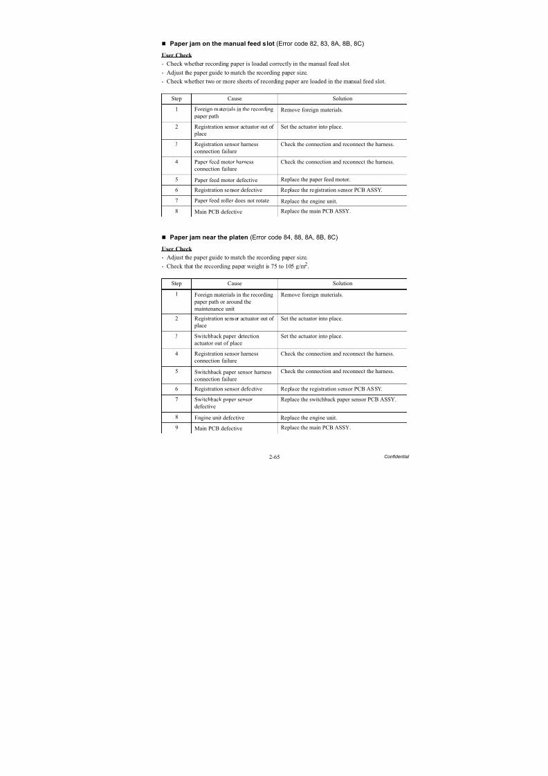
8/15/2019 Brother MFC 6510dw Sm
http://slidepdf.com/reader/full/brother-mfc-6510dw-sm 95/392
2-65 Confidential
Paper jam on the manual feed slot (Error code 82, 83, 8A, 8B, 8C)
User Check
- Check whether recording paper is loaded correctly in the manual feed slot.
- Adjust the paper guide to match the recording paper size.
- Check whether two or more sheets of recording paper are loaded in the manual feed slot.
Paper jam near the platen (Error code 84, 88, 8A, 8B, 8C)
User Check
- Adjust the paper guide to match the recording paper size.
- Check that the reccording paper weight is 75 to 105 g/m2.
Step Cause Solution
1 Foreign materials in the recording paper path
Remove foreign materials.
2 Registration sensor actuator out of place
Set the actuator into place.
3 Registration sensor harnessconnection failure
Check the connection and reconnect the harness.
4 Paper feed motor harnessconnection failure
Check the connection and reconnect the harness.
5 Paper feed motor defective Replace the paper feed motor.
6 Registration sensor defective Replace the registration sensor PCB ASSY.
7 Paper feed roller does not rotate Replace the engine unit.
8 Main PCB defective Replace the main PCB ASSY.
Step Cause Solution
1 Foreign materials in the recording paper path or around themaintenance unit
Remove foreign materials.
2 Registration sensor actuator out of place
Set the actuator into place.
3 Switchback paper detectionactuator out of place
Set the actuator into place.
4 Registration sensor harnessconnection failure
Check the connection and reconnect the harness.
5 Switchback paper sensor harnessconnection failure
Check the connection and reconnect the harness.
6 Registration sensor defective Replace the registration sensor PCB ASSY.
7 Switchback paper sensordefective
Replace the switchback paper sensor PCB ASSY.
8 Engine unit defective Replace the engine unit.
9 Main PCB defective Replace the main PCB ASSY.
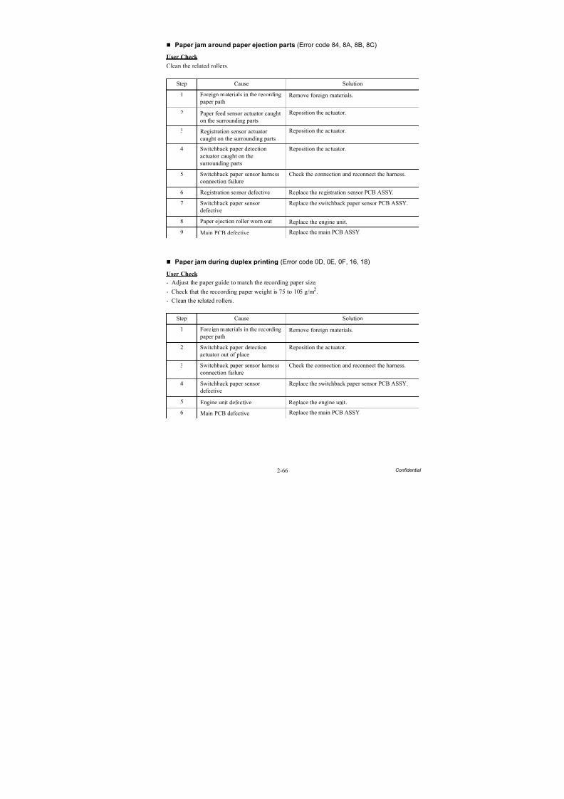
8/15/2019 Brother MFC 6510dw Sm
http://slidepdf.com/reader/full/brother-mfc-6510dw-sm 96/392
2-66 Confidential
Paper jam around paper ejection parts (Error code 84, 8A, 8B, 8C)
User Check
Clean the related rollers.
Paper jam during duplex printing (Error code 0D, 0E, 0F, 16, 18)
User Check
- Adjust the paper guide to match the recording paper size.
- Check that the reccording paper weight is 75 to 105 g/m2.
- Clean the related rollers.
Step Cause Solution
1 Foreign materials in the recording paper path
Remove foreign materials.
2 Paper feed sensor actuator caughton the surrounding parts
Reposition the actuator.
3 Registration sensor actuatorcaught on the surrounding parts
Reposition the actuator.
4 Switchback paper detectionactuator caught on thesurrounding parts
Reposition the actuator.
5 Switchback paper sensor harness
connection failure
Check the connection and reconnect the harness.
6 Registration sensor defective Replace the registration sensor PCB ASSY.
7 Switchback paper sensordefective
Replace the switchback paper sensor PCB ASSY.
8 Paper ejection roller worn out Replace the engine unit.
9 Main PCB defective Replace the main PCB ASSY.
Step Cause Solution
1 Foreign materials in the recording paper path
Remove foreign materials.
2 Switchback paper detectionactuator out of place
Reposition the actuator.
3 Switchback paper sensor harnessconnection failure
Check the connection and reconnect the harness.
4 Switchback paper sensordefective
Replace the switchback paper sensor PCB ASSY.
5 Engine unit defective Replace the engine unit.
6 Main PCB defective Replace the main PCB ASSY.
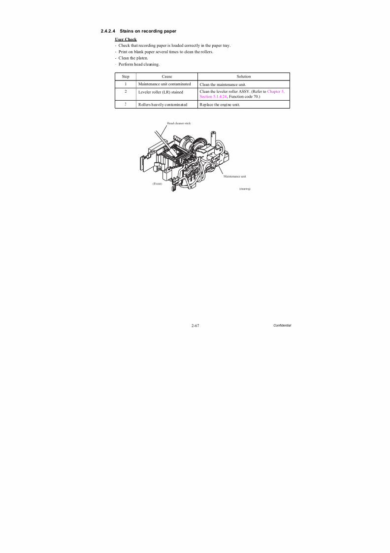
8/15/2019 Brother MFC 6510dw Sm
http://slidepdf.com/reader/full/brother-mfc-6510dw-sm 97/392
2-67 Confidential
2.4.2.4 Stains on recording paper
User Check
- Check that recording paper is loaded correctly in the paper tray.
- Print on blank paper several times to clean the rollers.
- Clean the platen.
- Perform head cleaning.
Step Cause Solution
1 Maintenance unit contaminated Clean the maintenance unit.
2 Leveler roller (LR) stained Clean the leveler roller ASSY. (Refer to Chapter 5, Section 5.1.4.24, Function code 70.)
3 Rollers heavily contaminated Replace the engine unit.
Maintenance unit
(Front)
(cleaning)
Head cleaner stick
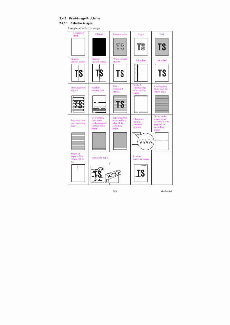
8/15/2019 Brother MFC 6510dw Sm
http://slidepdf.com/reader/full/brother-mfc-6510dw-sm 98/392
2-68 Confidential
2.4.3 Print-image Problems
2.4.3.1 Defective images
Examples of defective images
Completely
blank
All black Random color Light Dark
Straightvertical stripes
Blurredvertical stripes
White verticalstreaks
Ink splash Ink splash
Print edges notaligned
Randommissing dots
Whitehorizontalstreaks
Stainedleading edgeof recording
paper
Overlappinglines over thewhole page
Separated linesover the whole
page
Overlappinglines at thetrailing edge ofthe recording
paper
Separated linesat the trailingedge of therecording
paper
Charactershavingshadows(ghost)
Stains in thecenter of, orover the whole
page of, therecording
paper
Traces of paper pull-inrollers (T1 orT2)
Dirt on the paper Randomhorizontal stains
VWXYZ
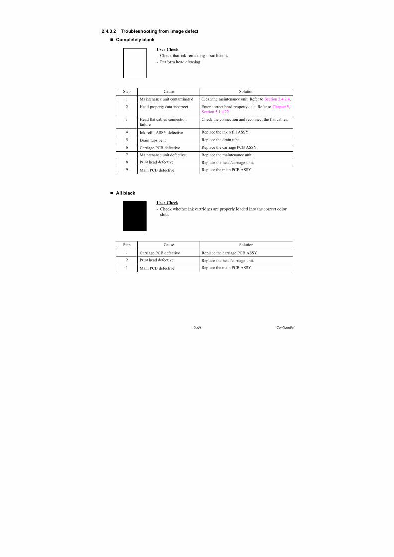
8/15/2019 Brother MFC 6510dw Sm
http://slidepdf.com/reader/full/brother-mfc-6510dw-sm 99/392
2-69 Confidential
2.4.3.2 Troubleshooting from image defect
Completely blank
All black
User Check
- Check that ink remaining is sufficient.
- Perform head cleaning.
Step Cause Solution
1 Maintenance unit contaminated Clean the maintenance unit. Refer to Section 2.4.2.4.
2 Head property data incorrect Enter correct head property data. Refer to Chapter 5,Section 5.1.4.22.
3 Head flat cables connection
failure
Check the connection and reconnect the flat cables.
4 Ink refill ASSY defective Replace the ink refill ASSY.
5 Drain tubs bent Replace the drain tube.
6 Carriage PCB defective Replace the carriage PCB ASSY.
7 Maintenance unit defective Replace the maintenance unit.
8 Print head defective Replace the head/carriage unit.
9 Main PCB defective Replace the main PCB ASSY.
User Check
- Check whether ink cartridges are properly loaded into the correct colorslots.
Step Cause Solution
1 Carriage PCB defective Replace the carriage PCB ASSY.
2 Print head defective Replace the head/carriage unit.
3 Main PCB defective Replace the main PCB ASSY.
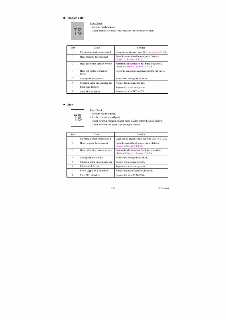
8/15/2019 Brother MFC 6510dw Sm
http://slidepdf.com/reader/full/brother-mfc-6510dw-sm 100/392
2-70 Confidential
Random color
Light
User Check
- Perform head cleaning.
- Check that ink cartridges are loaded in the correct color slots.
Step Cause Solution
1 Maintenance unit contaminated Clean the maintenance unit. Refer to Section 2.4.2.4.
2 Head property data incorrect Enter the correct head property data. Refer toChapter 5, Section 5.1.4.22.
3 Head calibration data not written Perform head calibration. See Function code 02.(Refer to Chapter 5, Section 5.1.4.2.)
4 Head flat cables connectionfailure Check the connection and reconnect the flat cables.
5 Carriage PCB defective Replace the carriage PCB ASSY.
6 Clogging in the maintenance unit Replace the maintenance unit.
7 Print head defective Replace the head/carriage unit.
8 Main PCB defective Replace the main PCB ASSY.
User Check
- Perform head cleaning.
- Replace the ink cartridge(s).
- Check whether recording paper being used is within the specification.
- Check whether the paper type setting is correct.
Step Cause Solution
1 Maintenance unit contaminated Clean the maintenance unit. Refer to Section 2.4.2.4.
2 Head property data incorrect Enter the correct head property data. Refer toChapter 5, Section 5.1.4.22.
3 Head calibration data not written Perform head calibration. See Function code 02.(Refer to Chapter 5, Section 5.1.4.2.)
4 Carriage PCB defective Replace the carriage PCB ASSY.
5 Clogging in the maintenance unit Replace the maintenance unit.
6 Print head defective Replace the head/carriage unit.
7 Power supply PCB defective Replace the power supply PCB ASSY.
8 Main PCB defective Replace the main PCB ASSY.
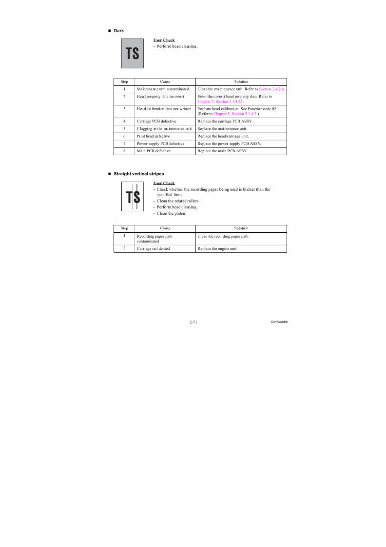
8/15/2019 Brother MFC 6510dw Sm
http://slidepdf.com/reader/full/brother-mfc-6510dw-sm 101/392
2-71 Confidential
Dark
Straight vertical stripes
User Check
- Perform head cleaning.
Step Cause Solution
1 Maintenance unit contaminated Clean the maintenance unit. Refer to Section 2.4.2.4.
2 Head property data incorrect Enter the correct head property data. Refer toChapter 5, Section 5.1.4.22.
3 Head calibration data not written Perform head calibration. See Function code 02.(Refer to Chapter 5, Section 5.1.4.2.)
4 Carriage PCB defective Replace the carriage PCB ASSY.5 Clogging in the maintenance unit Replace the maintenance unit.
6 Print head defective Replace the head/carriage unit.
7 Power supply PCB defective Replace the power supply PCB ASSY.
8 Main PCB defective Replace the main PCB ASSY.
User Check - Check whether the recording paper being used is thicker than the
specified limit.
- Clean the related rollers.
- Perform head cleaning.
- Clean the platen.
Step Cause Solution
1 Recording paper pathcontaminated
Clean the recording paper path.
2 Carriage rail dented Replace the engine unit.
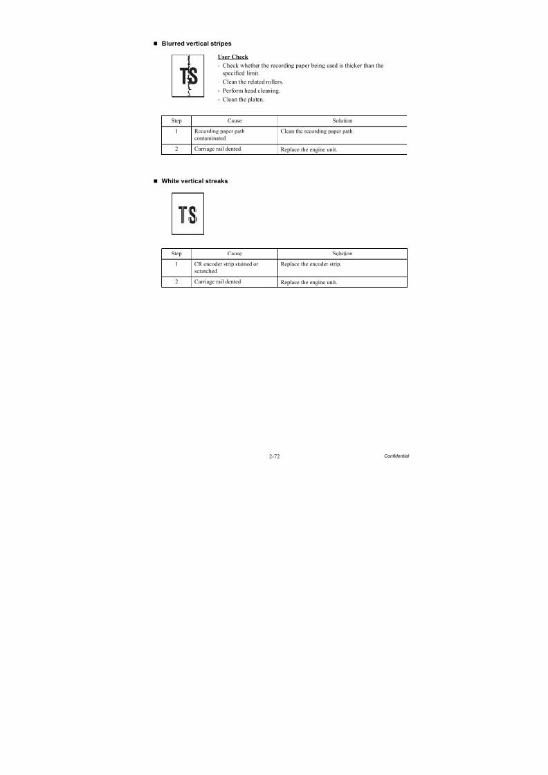
8/15/2019 Brother MFC 6510dw Sm
http://slidepdf.com/reader/full/brother-mfc-6510dw-sm 102/392
2-72 Confidential
Blurred vertical stripes
White vertical streaks
User Check
- Check whether the recording paper being used is thicker than thespecified limit.
- Clean the related rollers.
- Perform head cleaning.
- Clean the platen.
Step Cause Solution
1 Recording paper pathcontaminated
Clean the recording paper path.
2 Carriage rail dented Replace the engine unit.
Step Cause Solution
1 CR encoder strip stained orscratched
Replace the encoder strip.
2 Carriage rail dented Replace the engine unit.
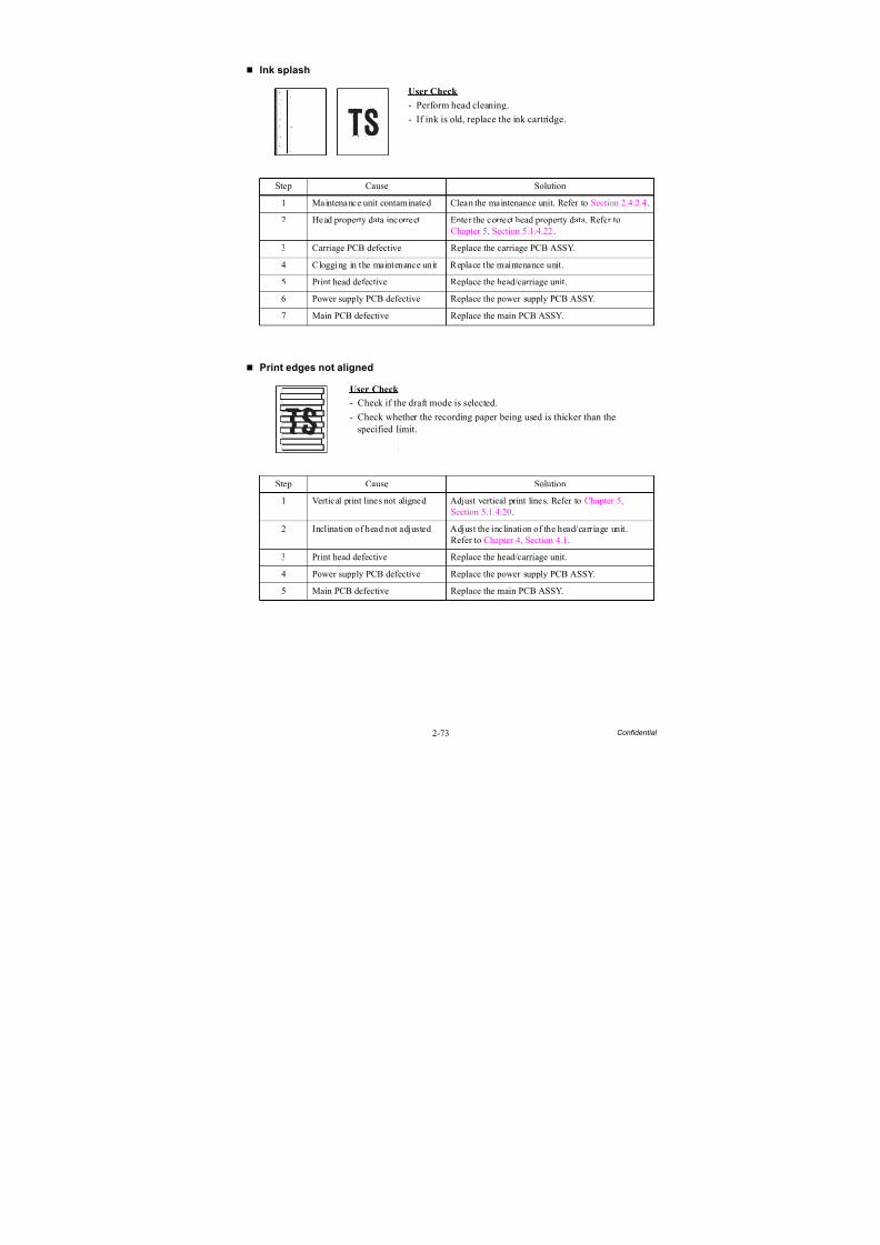
8/15/2019 Brother MFC 6510dw Sm
http://slidepdf.com/reader/full/brother-mfc-6510dw-sm 103/392
2-73 Confidential
Ink splash
Print edges not aligned
User Check
- Perform head cleaning.
- If ink is old, replace the ink cartridge.
Step Cause Solution
1 Maintenance unit contaminated Clean the maintenance unit. Refer to Section 2.4.2.4.
2 Head property data incorrect Enter the correct head property data. Refer toChapter 5, Section 5.1.4.22.
3 Carriage PCB defective Replace the carriage PCB ASSY.
4 Clogging in the maintenance unit Replace the maintenance unit.
5 Print head defective Replace the head/carriage unit.
6 Power supply PCB defective Replace the power supply PCB ASSY.
7 Main PCB defective Replace the main PCB ASSY.
User Check
- Check if the draft mode is selected.
- Check whether the recording paper being used is thicker than thespecified limit.
Step Cause Solution
1 Vertical print lines not aligned Adjust vertical print lines. Refer to Chapter 5,Section 5.1.4.20.
2 Inclination of head not adjusted Adjust the inclination of the head/carriage unit.Refer to Chapter 4, Section 4.1.
3 Print head defective Replace the head/carriage unit.4 Power supply PCB defective Replace the power supply PCB ASSY.
5 Main PCB defective Replace the main PCB ASSY.
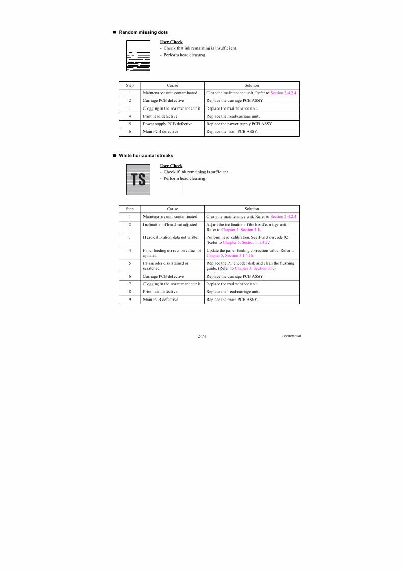
8/15/2019 Brother MFC 6510dw Sm
http://slidepdf.com/reader/full/brother-mfc-6510dw-sm 104/392
2-74 Confidential
Random missing dots
White horizontal streaks
User Check
- Check that ink remaining is insufficient.
- Perform head cleaning.
Step Cause Solution
1 Maintenance unit contaminated Clean the maintenance unit. Refer to Section 2.4.2.4.
2 Carriage PCB defective Replace the carriage PCB ASSY.
3 Clogging in the maintenance unit Replace the maintenance unit.
4 Print head defective Replace the head/carriage unit.
5 Power supply PCB defective Replace the power supply PCB ASSY.
6 Main PCB defective Replace the main PCB ASSY.
User Check
- Check if ink remaining is sufficient.
- Perform head cleaning.
Step Cause Solution
1 Maintenance unit contaminated Clean the maintenance unit. Refer to Section 2.4.2.4.
2 Inclination of head not adjusted Adjust the inclination of the head/carriage unit.Refer to Chapter 4, Section 4.1.
3 Head calibration data not written Perform head calibration. See Function code 02.(Refer to Chapter 5, Section 5.1.4.2.)
4 Paper feeding correction value not
updated
Update the paper feeding correction value. Refer to
Chapter 5, Section 5.1.4.16.5 PF encoder disk stained or
scratchedReplace the PF encoder disk and clean the flushingguide. (Refer to Chapter 3, Section 3.1.)
6 Carriage PCB defective Replace the carriage PCB ASSY.
7 Clogging in the maintenance unit Replace the maintenance unit.
8 Print head defective Replace the head/carriage unit.
9 Main PCB defective Replace the main PCB ASSY.
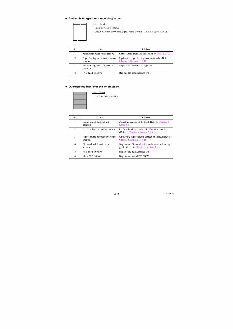
8/15/2019 Brother MFC 6510dw Sm
http://slidepdf.com/reader/full/brother-mfc-6510dw-sm 105/392
2-75 Confidential
Stained leading edge of recording paper
Overlapping lines over the whole page
User Check
- Perform head cleaning.
- Check whether recording paper being used is within the specification.
Step Cause Solution
1 Maintenance unit contaminated Clean the maintenance unit. Refer to Section 2.4.2.4.
2 Paper feeding correction value notupdated
Update the paper feeding correction value. Refer toChapter 5, Section 5.1.4.16.
3 Head/carriage unit not mountedcorrectly
Reposition the head/carriage unit.
4 Print head defective Replace the head/carriage unit.
User Check
- Perform head cleaning.
Step Cause Solution
1 Inclination of the head notadjusted
Adjust inclination of the head. Refer to Chapter 4,Section 4.1.
2 Head calibration data not written Perform head calibration. See Function code 02.(Refer to Chapter 5, Section 5.1.4.2.)
3 Paper feeding correction value notupdated
Update the paper feeding correction value. Refer toChapter 5, Section 5.1.4.16.
4 PF encoder disk stained or
scratched
Replace the PF encoder disk and clean the flushing
guide. (Refer to Chapter 3, Section 3.1.)5 Print head defective Replace the head/carriage unit.
6 Main PCB defective Replace the main PCB ASSY.
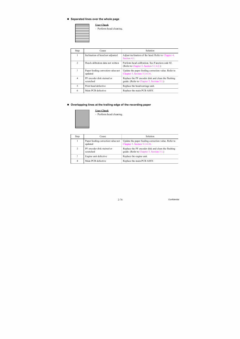
8/15/2019 Brother MFC 6510dw Sm
http://slidepdf.com/reader/full/brother-mfc-6510dw-sm 106/392
2-76 Confidential
Separated lines over the whole page
Overlapping lines at the trailing edge of the recording paper
User Check
- Perform head cleaning.
Step Cause Solution
1 Inclination of head not adjusted Adjust inclination of the head. Refer to Chapter 4,Section 4.1.
2 Head calibration data not written Perform head calibration. See Function code 02.(Refer to Chapter 5, Section 5.1.4.2.)
3 Paper feeding correction value notupdated
Update the paper feeding correction value. Refer toChapter 5, Section 5.1.4.16.
4 PF encoder disk stained orscratched
Replace the PF encoder disk and clean the flushingguide. (Refer to Chapter 3, Section 3.1.)
5 Print head defective Replace the head/carriage unit.
6 Main PCB defective Replace the main PCB ASSY.
User Check
- Perform head cleaning.
Step Cause Solution
1 Paper feeding correction value notupdated
Update the paper feeding correction value. Refer toChapter 5, Section 5.1.4.16.
2 PF encoder disk stained or
scratched
Replace the PF encoder disk and clean the flushing
guide. (Refer to Chapter 3, Section 3.1.)3 Engine unit defective Replace the engine unit.
4 Main PCB defective Replace the main PCB ASSY.
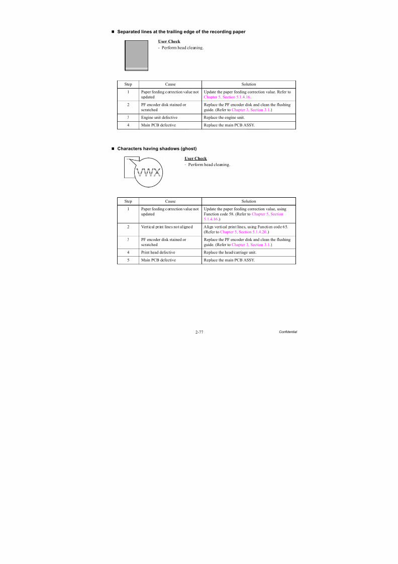
8/15/2019 Brother MFC 6510dw Sm
http://slidepdf.com/reader/full/brother-mfc-6510dw-sm 107/392
2-77 Confidential
Separated lines at the trailing edge of the recording paper
Characters having shadows (ghost)
User Check
- Perform head cleaning.
Step Cause Solution
1 Paper feeding correction value notupdated
Update the paper feeding correction value. Refer toChapter 5, Section 5.1.4.16.
2 PF encoder disk stained orscratched
Replace the PF encoder disk and clean the flushingguide. (Refer to Chapter 3, Section 3.1.)
3 Engine unit defective Replace the engine unit.
4 Main PCB defective Replace the main PCB ASSY.
User Check
- Perform head cleaning.
Step Cause Solution
1 Paper feeding correction value notupdated
Update the paper feeding correction value, usingFunction code 58. (Refer to Chapter 5, Section5.1.4.16.)
2 Vertical print lines not aligned Align vertical print lines, using Function code 65.(Refer to Chapter 5, Section 5.1.4.20.)
3 PF encoder disk stained orscratched
Replace the PF encoder disk and clean the flushingguide. (Refer to Chapter 3, Section 3.1.)
4 Print head defective Replace the head/carriage unit.5 Main PCB defective Replace the main PCB ASSY.
VWXYZ
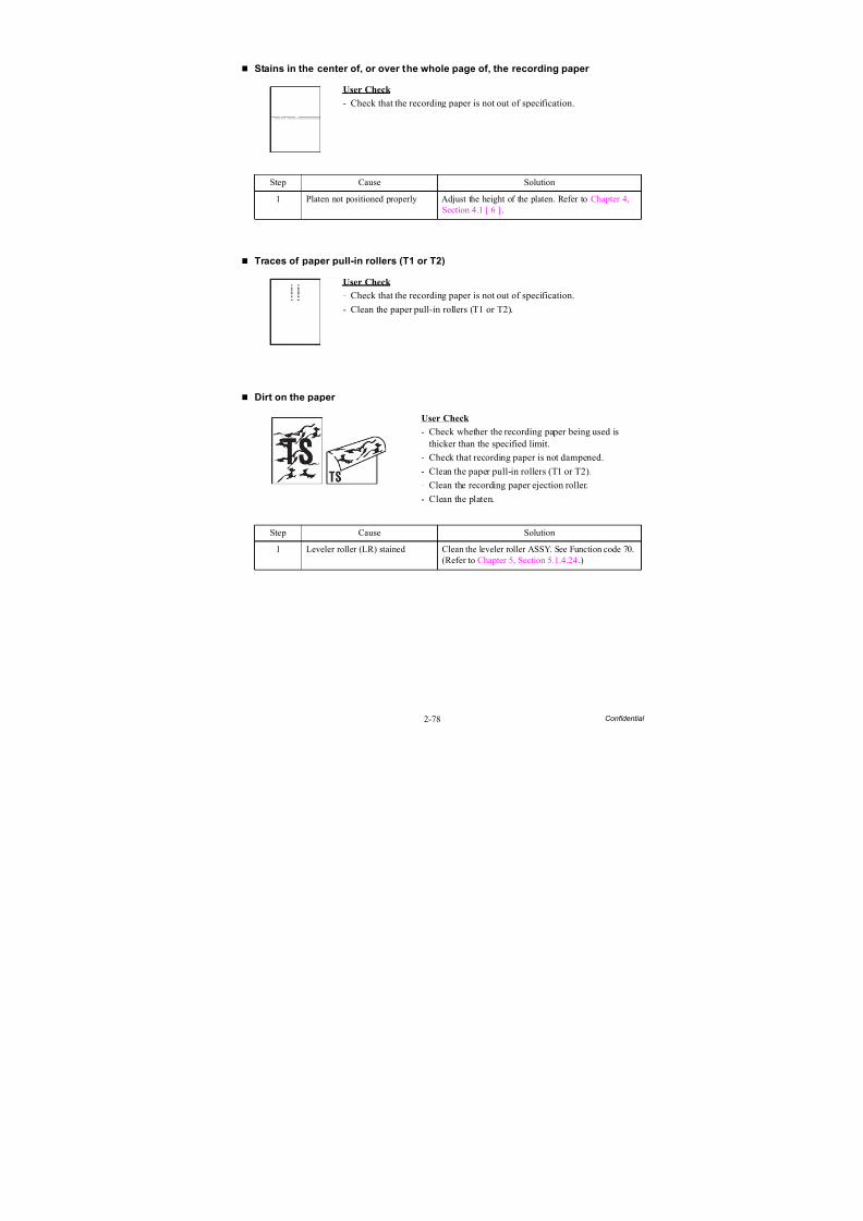
8/15/2019 Brother MFC 6510dw Sm
http://slidepdf.com/reader/full/brother-mfc-6510dw-sm 108/392
2-78 Confidential
Stains in the center of, or over the whole page of, the recording paper
Traces of paper pull-in rollers (T1 or T2)
Dirt on the paper
User Check
- Check that the recording paper is not out of specification.
Step Cause Solution
1 Platen not positioned properly Adjust the height of the platen. Refer to Chapter 4,Section 4.1 [ 6 ].
User Check
- Check that the recording paper is not out of specification.
- Clean the paper pull-in rollers (T1 or T2).
User Check
- Check whether the recording paper being used isthicker than the specified limit.
- Check that recording paper is not dampened.
- Clean the paper pull-in rollers (T1 or T2).
- Clean the recording paper ejection roller.
- Clean the platen.
Step Cause Solution
1 Leveler roller (LR) stained Clean the leveler roller ASSY. See Function code 70.(Refer to Chapter 5, Section 5.1.4.24.)
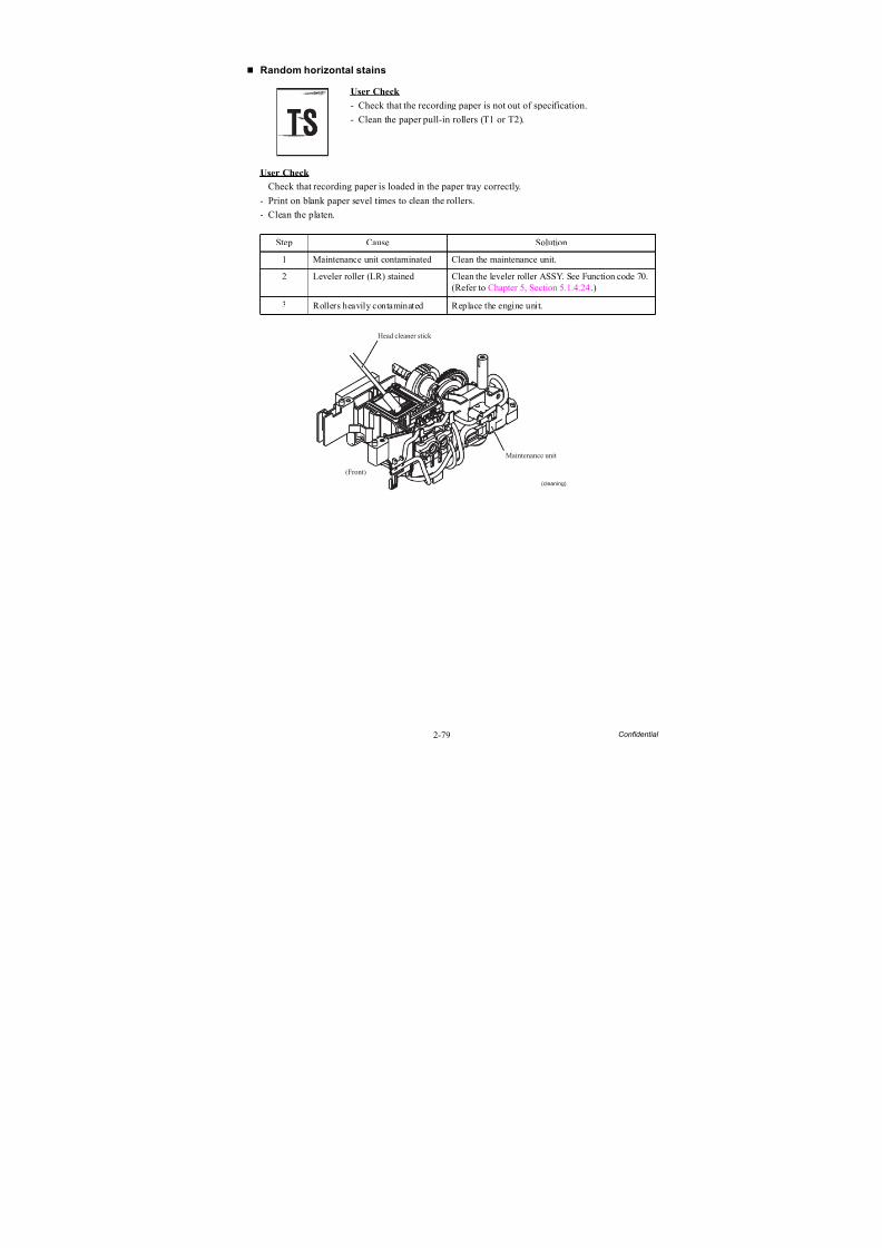
8/15/2019 Brother MFC 6510dw Sm
http://slidepdf.com/reader/full/brother-mfc-6510dw-sm 109/392
2-79 Confidential
Random horizontal stains
User Check
- Check that recording paper is loaded in the paper tray correctly.
- Print on blank paper sevel times to clean the rollers.
- Clean the platen.
User Check
- Check that the recording paper is not out of specification.
- Clean the paper pull-in rollers (T1 or T2).
Step Cause Solution
1 Maintenance unit contaminated Clean the maintenance unit.
2 Leveler roller (LR) stained Clean the leveler roller ASSY. See Function code 70.(Refer to Chapter 5, Section 5.1.4.24.)
3 Rollers heavily contaminated Replace the engine unit.
Maintenance unit
(Front)
(cleaning)
Head cleaner stick

8/15/2019 Brother MFC 6510dw Sm
http://slidepdf.com/reader/full/brother-mfc-6510dw-sm 110/392
2-80 Confidential
2.4.4 Software-related Problems
The end user can solve problems pertaining to software, for instance, print cannot be made forma computer although test print and printer setting print can be made from the machine byfollowing the User Check items. If the same problem occurs, follow each procedure in the order of the number described in the Step column in the tables below.
2.4.4.1 Cannot print data
User Check
- Check that the USB cable or LAN cable is not damaged.
- Check that the correct machine is selected if you have an interface switching device.
- Check the descriptions of the software setting in the user’s guide.
- Revert the settings to the factory defaults. (Refer to the user’s guide.)
- Check the driver settings.
Step Cause Solution
1 Main PCB defective Replace the main PCB ASSY.

8/15/2019 Brother MFC 6510dw Sm
http://slidepdf.com/reader/full/brother-mfc-6510dw-sm 111/392
8/15/2019 Brother MFC 6510dw Sm
http://slidepdf.com/reader/full/brother-mfc-6510dw-sm 112/392
2-82 Confidential
2.4.6 Document Feeding Problems
2.4.6.1 Cannot feed documents
User Check
- Set documents fully into the document tray.
- Limit the number of documents to be set in the ADF to a maximum of 35 sheets.- Close the ADF cover tight.
- Clean the related rollers.
2.4.6.2 Document double feeding
User Check
- Check if document thinner than the specified one is used.
Step Cause Solution
1 Document detection actuator outof place
Set the actuator into place.
2 ADF motor harness connectionfailure
Check the connection and reconnect the harness.
3 Document detection/width sensor
harness connection failure
Check the connection and reconnect the harness.
4 Document detection sensordefective
Replace the document detection/width sensor PCBASSY.
5 Document separation rollerdefective
Replace the document pull-in/separation rollerASSY.
6 ADF motor defective Replace the ADF motor ASSY.
7 Main PCB defective Replace the main PCB ASSY.
Step Cause Solution
1 Separation rubber worn out Replace the separation rubber.
8/15/2019 Brother MFC 6510dw Sm
http://slidepdf.com/reader/full/brother-mfc-6510dw-sm 113/392
2-83 Confidential
2.4.6.3 Document jam
Document jam in the ADF cover (Error code A3, etc.)
User Check
- Check if paper particles such as document broken are jammed around the document slot.
Document jam inside the ADF (Error code A2, etc.)
User Check - Check whether the document scanned is 147.3 mm or shorter in length.
Step Cause Solution
1 Foreign materials around andinside the ADF cover
Remove foreign materials.
2 Connection failure of thedocument detection/width &scanning position (first side)sensors harness
Check the connection and reconnect the harness.
3 Connection failure of thedocument scanning positionsensor (second side) harness
Check the connection and reconnect the harness.
4 Document scanning positionsensor (for first side scanning)defective
Replace the sensor PCB ASSY.
5 Document scanning positionsensor (for second side scanning)defective
Replace the sensor PCB ASSY.
6 ADF motor defective Replace the ADF motor.
Step Cause Solution
1 Foreign materials inside the ADF. Remove foreign materials.
2 Document scanning positiondetection actuator (for first sidescanning) caught on thesurrounding parts
Reposition the actuator.
3 Document scanning positiondetection actuator (for second sidescanning) caught on thesurrounding parts
Reposition the actuator.
4 Document pressure bar out of place
Set the document pressure bar into place.
5 Document scanning positionsensor (for first side scanning)defective
Replace the sensor PCB ASSY.
6 Document scanning positionsensor (for second side scanning)defective
Replace the sensor PCB ASSY.
7 Document feed roller 2 defective Replace the ADF & document cover ASSY.
8/15/2019 Brother MFC 6510dw Sm
http://slidepdf.com/reader/full/brother-mfc-6510dw-sm 114/392
2-84 Confidential
Document jam around document ejection section
2.4.6.4 Wrinkles on documents
User Check
- Check that documents are loaded correctly in the ADF unit.
- Check that the document guides match the document size.
- Check that documents are not curled.
2.4.6.5 Cannot detect the document size correctly
Step Cause Solution
1 Foreign materials arounddocument ejection section
Remove foreign materials.
2 ADF drive gears brokenDocument ejection rollerdefective
Replace the ADF & document cover ASSY.
Step Cause Solution
1 Document separation roller wornout
Replace the document pull-in/separation rollerASSY.
2 Document feed rollers worn out Replace the document feed rollers.
Step Cause Solution
1 Document width detectionactuator out of place
Set the actuator into place.
2 Document width sensor defective Replace the document detection/width sensor PCBASSY.
3 Main PCB defective Replace the main PCB ASSY.
8/15/2019 Brother MFC 6510dw Sm
http://slidepdf.com/reader/full/brother-mfc-6510dw-sm 115/392
2-85 Confidential
2.4.7 Scanned-image Problems
2.4.7.1 Defective images
2.4.7.2 Troubleshooting from image defect
Light
Light Scanning position failure Dark
Completely blank Vertical streaksWhite verticalstreaks
User Check
- Check if the contrast is set to "Light."
- Clean the scanner glass or the ADF glass.- Clean the CIS glass in the ADF unit.
Step Cause Solution
1 White level data defective Obtain the white level data, using Function code 55.(Refer to Chapter 5, Section 5.1.4.15.)
2 Document pressure bar stained Clean the document pressure bar.
3 Second side scanning CIS
defective
Replace the CIS unit.
4 First side scanning CIS unitdefective
Replace the scanner cover (scanner unit).
5 Main PCB defective Replace the main PCB ASSY.
8/15/2019 Brother MFC 6510dw Sm
http://slidepdf.com/reader/full/brother-mfc-6510dw-sm 116/392
8/15/2019 Brother MFC 6510dw Sm
http://slidepdf.com/reader/full/brother-mfc-6510dw-sm 117/392
2-87 Confidential
Dark
Completely blank
User Check
- Check if the contrast is set to "Dark."
Step Cause Solution
1 White level data defective Obtain the white level data, using Function code 55.(Refer to Chapter 5, Section 5.1.4.15.)
2 First side scanning CIS unitdefective
Replace the scanner cover (scanner unit).
3 Second side scanning CISdefective
Replace the CIS unit (for second side scanning).
4 Main PCB defective Replace the main PCB ASSY.
User Check
- Check whether documents are loaded upside down.
- Check that documents are correctly loaded in the ADF.
Step Cause Solution
1 White level data defective Obtain the white level data, using Function code 55.(Refer to Chapter 5, Section 5.1.4.15.)
2 First side scanning CIS unitdefective
Replace the scanner cover (scanner unit).
3 Second side scanning CISdefective
Replace the CIS unit (for second side scanning).
4 Main PCB defective Replace the main PCB ASSY.
8/15/2019 Brother MFC 6510dw Sm
http://slidepdf.com/reader/full/brother-mfc-6510dw-sm 118/392
2-88 Confidential
Vertical streaks
White vertical streaks
User Check
- Check whether the ADF glass or document cover glass isstained.
- Clean the CIS glass in the ADF unit.
Step Cause Solution
1 First side scanning CIS unitdefective
Replace the scanner cover (scanner unit).
2 Second side scanning CISdefective
Replace the second side scanning CIS unit.
User Check
- Check whether the ADF glass or document cover glass is stained.
- Clean the CIS glass in the ADF unit.
Step Cause Solution
1 First side scanning CIS unitdefective
Replace the scanner cover (scanner unit).
2 Second side scanning CISdefective
Replace the second side scanning CIS unit.
8/15/2019 Brother MFC 6510dw Sm
http://slidepdf.com/reader/full/brother-mfc-6510dw-sm 119/392
8/15/2019 Brother MFC 6510dw Sm
http://slidepdf.com/reader/full/brother-mfc-6510dw-sm 120/392
2-90 Confidential
2.4.8.3 Lamps on the control panel does not light
2.4.8.4 Touch panel inoperative (For models with touch panel)
Step Cause Solution
1 Rubber keypad not set in place Reposition the control panel ASSY.
2 Panel-main harness connection
failure
Check the connection and reconnect the harness.
3 Rubber keypad defective Replace the rubber keypad.
4 Control panel PCB defective Replace the control panel PCB ASSY.
5 Main PCB defective Replace the main PCB ASSY.
Step Cause Solution1 Touch panel alignment off
(For models with touch panel)Adjust the touch panel, using Function code 78.(Refer to Chapter 5, Section 5.1.4.29.)
2 Touch panel harness connectionfailure
Check the connection and reconnect the harness.
3 Touch panel defective Replace the LCD unit.
4 Main PCB defective Replace the main PCB ASSY.
8/15/2019 Brother MFC 6510dw Sm
http://slidepdf.com/reader/full/brother-mfc-6510dw-sm 121/392
8/15/2019 Brother MFC 6510dw Sm
http://slidepdf.com/reader/full/brother-mfc-6510dw-sm 122/392
2-92 Confidential
2.4.9.3 No faxes can be received
User Check
- Check if the appropriate telephone cord is used or it is plugged in the socket.
- Check the dial mode setting again.
2.4.9.4 The ringer does not sound
User Check - Set the number of ringers to any number except "0."
- Set the ringer volume to any level except "OFF."
2.4.9.5 In on-hook dialing, the speaker does not sound
User Check
- Check if the telephone cord is plugged in the socket.
Step Cause Solution
1 Connection failure of the main-MJ harnesses (LINE and EXT)
Check the connection and reconnect the harnesses.
2 MJ PCB defective Replace the MJ PCB ASSY.
3 Main PCB defective Replace the main PCB ASSY.
Step Cause Solution
1 Speaker harness connectionfailure
Check the connection and reconnect the harness.
2 Connection failure of the main-MJ harnesses (LINE and EXT)
Check the connection and reconnect the harnesses.
3 MJ PCB defective Replace the MJ PCB ASSY.
4 Speaker defective Replace the speaker unit.
5 Main PCB defective Replace the main PCB ASSY.
Step Cause Solution1 Speaker harness connection
failure
Check the connection and reconnect the harness.
2 Rubber keypad defective Replace the rubber keypad.
3 Control panel PCB defective Replace the control panel PCB ASSY.
4 MJ PCB defective Replace the MJ PCB ASSY.
5 Speaker defective Replace the speaker unit.
6 Main PCB defective Replace the main PCB ASSY.
8/15/2019 Brother MFC 6510dw Sm
http://slidepdf.com/reader/full/brother-mfc-6510dw-sm 123/392
2-93 Confidential
2.4.9.6 Dial does not switch between tone and pulse
2.4.9.7 A communications error occurs
User Check
- Check if the telephone cord that comes with the machine is used.
2.4.9.8 Receive mode cannot be changed
2.4.9.9 Caller ID not displayed
Step Cause Solution
1 Main PCB defective Replace the main PCB ASSY.
Step Cause Solution
1 MJ PCB defective Replace the MJ PCB ASSY.
2 Main PCB defective Replace the main PCB ASSY.
Step Cause Solution
1 The BT Call Sign mode is ON. Turn the mode OFF.
2 The Distinctive Ring mode is ON. Turn the mode OFF.
Step Cause Solution
1 Main PCB defective Replace the main PCB ASSY.
8/15/2019 Brother MFC 6510dw Sm
http://slidepdf.com/reader/full/brother-mfc-6510dw-sm 124/392

8/15/2019 Brother MFC 6510dw Sm
http://slidepdf.com/reader/full/brother-mfc-6510dw-sm 125/392
2-95 Confidential
2.4.10.4 Memory errors
User Check
- Delete the stored data.
2.4.10.5 Paper tray set does not work
User Check
- Make a correct tray setting.
Step Cause Solution
1 Main PCB defective Replace the main PCB ASSY.
Step Cause Solution
1 Main PCB defective Replace the main PCB ASSY.
8/15/2019 Brother MFC 6510dw Sm
http://slidepdf.com/reader/full/brother-mfc-6510dw-sm 126/392
3-1 Confidential
CHAPTER 3 DISASSEMBLY AND ASSEMBLY
This chapter details procedures for disassembling and reassembling the machine together with relatednotes. The disassembly order flow provided enables you to see at a glance the quickest way to get to
component(s) involved.At the start of a disassembly job, you check the disassembly order flow that guides you through ashortcut to the target components.
This chapter also covers screw tightening torques and lubrication points to which the specifiedlubricants should be applied during reassembly jobs.
3.1 SAFETY PRECAUTIONS AND HANDLING NOTES
To prevent the creation of secondary problems by mishandling, observe the following precautions during maintenance work.
(1) Be careful not to lose screws, washers, or other parts removed for parts replacement.
(2) When using soldering irons and other heat-generating tools, take care not to damage the
resin parts such as wires, PCBs, and covers.(3) Static electricity charged in your body may damage electronic parts.
Before handling the PCBs, touch a metal portion of the machine to discharge staticelectricity charged in your body. When transporting PCBs, be sure to wrap them inconductive sheets.
When replacing the head/carriage unit, put on a grounding wrist band and perform the jobon a static mat. Also take care not to touch the conductor sections on the flat cables.
(4) Be sure to reinsert self-tapping screws correctly, if removed.
(5) Tighten screws to the torque values listed on the next page.
(6) When connecting or disconnecting cable connectors, hold the connector bodies not the
wires. If the connector has a lock, always slide the connector lock to unlock it.
(7) Before reassembly, apply the specified lubricant to the specified points. (Refer to Section3.5 in this chapter.)
(8) After repairs, check not only the repaired portion but also that the connectors and other related portions function properly before operation checks.
(9) Once the head/carriage unit prints, it will start head locking operation after five secondsfrom the end of printing. The head locking operation will take 5 to 10 seconds. NEVER unplug the power cord before the machine completes the head locking operation; doing sowill make the head/carriage unit unusable and require replacement with a new head/carriage unit.
When you receive the machine from the user or when you pack it for sending it back to theuser, check the head locking state.
Before replacing parts or units, unplug the power cord and telephone line.
In particular, when having access to the power supply inside the machine, make sure that the power cord is unplugged from the electrical outlet; when having access to the main PCB or MJ PCB*, make sure that both the power cord and telephone line are unplugged from theelectrical outlet.
WARNING RNIN
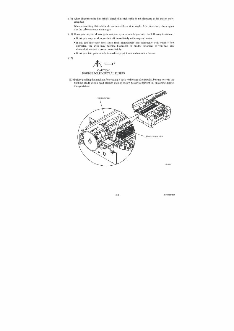
8/15/2019 Brother MFC 6510dw Sm
http://slidepdf.com/reader/full/brother-mfc-6510dw-sm 127/392
3-2 Confidential
(10) After disconnecting flat cables, check that each cable is not damaged at its end or short-circuited.
When connecting flat cables, do not insert them at an angle. After insertion, check againthat the cables are not at an angle.
(11) If ink gets on your skin or gets into your eyes or mouth, you need the following treatment.
• If ink gets on your skin, wash it off immediately with soap and water.
• If ink gets into your eyes, flush them immediately and thoroughly with water. If leftuntreated, the eyes may become bloodshot or mildly inflamed. If you feel anydiscomfort, consult a doctor immediately.
• If ink gets into your mouth, immediately spit it out and consult a doctor.
(12)
CAUTION
DOUBLE POLE/NEUTRAL FUSING
(13)Before packing the machine for sending it back to the user after repairs, be sure to clean theflushing guide with a head cleaner stick as shown below to prevent ink splashing duringtransportation.
(3_000)
Flushing guide
Head cleaner stick
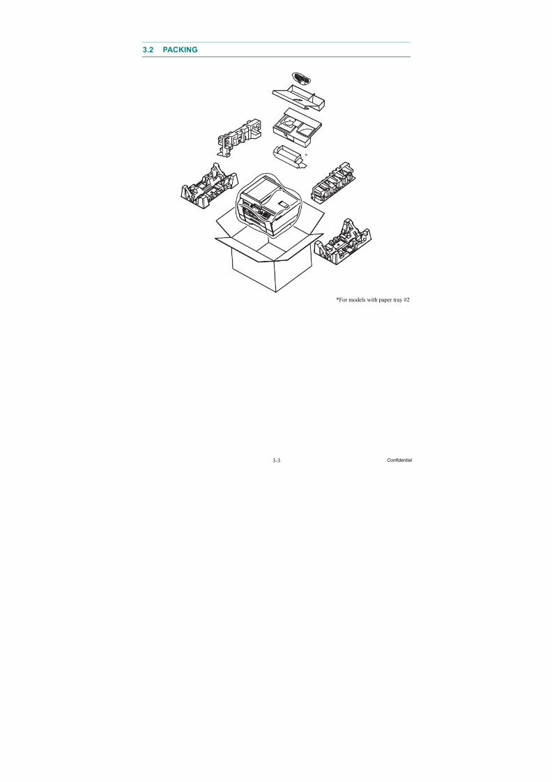
8/15/2019 Brother MFC 6510dw Sm
http://slidepdf.com/reader/full/brother-mfc-6510dw-sm 128/392
3-3 Confidential
3.2 PACKING
*For models with paper tray #2
*
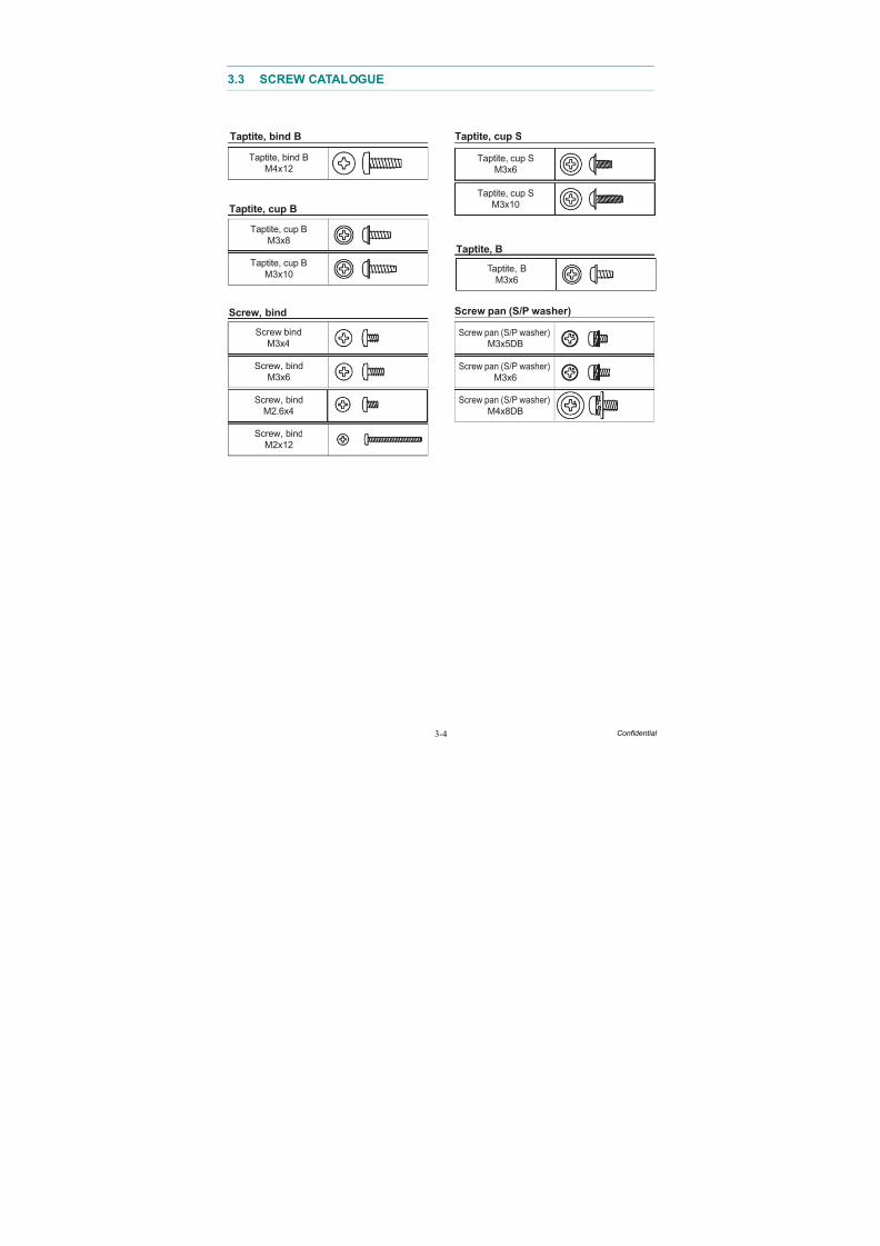
8/15/2019 Brother MFC 6510dw Sm
http://slidepdf.com/reader/full/brother-mfc-6510dw-sm 129/392
3-4 Confidential
3.3 SCREW CATALOGUE
Screw pan (S/P washer)Screw, bind
Taptite, bind B
Taptite, bind B
M4x12
Taptite, cup B
Taptite, cup B
M3x10
Screw, bind
M3x6
Screw, bind
M2.6x4
Screw pan (S/P washer)
M3x5DB
Screw, bind
M2x12
Taptite, cup B
M3x8Taptite, B
Taptite, cup S
Taptite, cup S
M3x6
Taptite, cup S
M3x10
Taptite, B
M3x6
Screw pan (S/P washer)
M4x8DB
Screw pan (S/P washer)
M3x6
Screw bind
M3x4
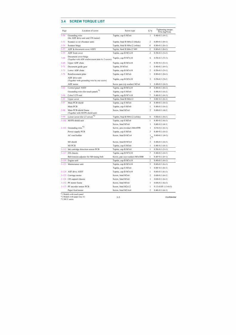
8/15/2019 Brother MFC 6510dw Sm
http://slidepdf.com/reader/full/brother-mfc-6510dw-sm 130/392
3-5 Confidential
3.4 SCREW TORQUE LIST
Page Location of screw Screw type Q’ty Tightening torque N•m (kgf •cm)
3-50 Grounding wire
(for ADF drive unit and CIS motor)
Taptite, cup S M3x6 1 0.40±0.1 (4±1)
3-53 Scanner cover (Scanner unit) Taptite, bind B M4x12 (black) 2 0.80±0.1 (8±1)
3-54 Scanner hinge Taptite, bind B M4x12 (white) 6 0.80±0.1 (8±1)
3-57 ADF & document cover ASSY Taptite, bind B M4x12 M9 2 0.80±0.1 (8±1)
3-59 ADF front cover Taptite, cup B M3x10 2 0.50±0.1 (5±1)
3-60Document cover hinge(Together with ADF reinforcement plate by 2 screws)
Taptite, cup B M3x10 6 0.50±0.1 (5±1)
3-69 Upper ADF chute Taptite, cup B M3x10 5 0.50±0.1 (5±1)
3-71 Document guide gear Taptite, B M3x6 1 0.40±0.1 (4±1)
3-73 Lower ADF chute Taptite, cup B M3x10 2 0.50±0.1 (5±1)
3-78 Reinforcement plate Taptite, cup S M3x6 1 0.80±0.1 (8±1)ADF drive unit(Together with grounding wire by one screw)
Taptite, cup B M3x10 3 0.50±0.1 (5±1)
ADF motor Screw pan (s/p washer) M3x6 1 0.40±0.1 (4±1)
3-82 Control panel ASSY Taptite, cup B M3x10 4 0.40±0.1 (4±1)
Grounding wire (for touch panel)*1 Taptite, cup S M3x6 1 0.40±0.1 (4±1)
3-84 Color LCD unit Taptite, cup B M3x10 2 0.40±0.1 (4±1)
3-91 Upper cover Taptite, bind B M4x12 7 0.80±0.1 (8±1)
3-97 Main PCB shield Taptite, cup S M3x6 4 0.40±0.1 (4±1)
Main PCB Taptite, cup S M3x6 1 0.40±0.1 (4±1)
3-98 Main PCB shield frame
(Together with MJ/PS shield unit)
Screw, bind M3x6 2 0.40±0.1 (4±1)
3-99 Lower cover (for LT cover)*2 Taptite, bind B M4x12 (white) 6 0.80±0.1 (8±1)
3-101 MJ/PS shield unit Taptite, cup S M3x6 1 0.40±0.1 (4±1)
Screw, bind M3x6 1 0.40±0.1 (4±1)
3-103 Grounding wire*3 Screw, pan (washer) M4x8DB 1 0.60±0.1 (6±1)
Power supply PCB Taptite, cup S M3x6 3 0.40±0.1 (4±1)
AC cord holder Screw, bind B M3x4 12*3
0.40±0.1 (4±1)
MJ shield Screw, bind B M3x4 2 0.40±0.1 (4±1)
MJ PCB Taptite, cup S M3x6 1 0.40±0.1 (4±1)
3-112 Ink cartridge detection sensor PCB Taptite, cup B M3x8 1 0.50±0.1 (5±1)3-117 DX chassis Taptite, cup B M3x10 2 0.40±0.1 (4±1)
Belt tension adjuster for SB timing belt Screw, pan (s/p washer) M3x5DB 1 0.40±0.1 (4±1)
3-119 Engine unit Taptite, cup B M3x10 2 0.40±0.1 (4±1)
3-123 Maintenance unit Taptite, cup B M3x10 3 0.60±0.1 (6±1)
Taptite, cup S M3x6 1 0.80±0.1 (8±1)
3-124 ASF drive ASSY Taptite, cup B M3x10 1 0.60±0.1 (6±1)
3-125 Carriage motor Screw, bind M3x6 2 0.60±0.1 (6±1)
3-126 CR support chassis Screw, bind M3x6 1 0.60±0.1 (6±1)
3-132 PF motor frame Screw, bind M3x6 1 0.60±0.1 (6±1)
3-133 PF encoder sensor PCB Screw, bind M2x12 1 0.15±0.05 (1.5±0.5)
Paper feed motor Screw, bind M2.6x4 2 0.40±0.1 (4±1)
*1 Models with touch panel*2 Models with paper tray #2*3 200 V series
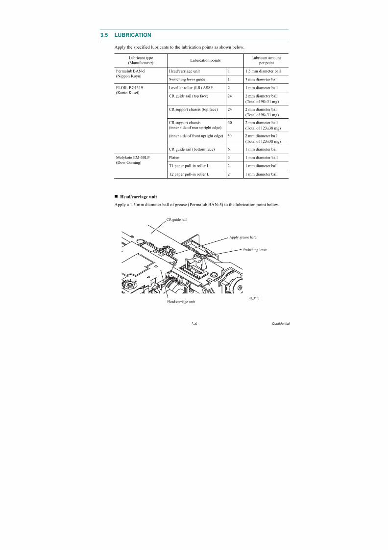
8/15/2019 Brother MFC 6510dw Sm
http://slidepdf.com/reader/full/brother-mfc-6510dw-sm 131/392
3-6 Confidential
3.5 LUBRICATION
Apply the specified lubricants to the lubrication points as shown below.
Head/carriage unit
Apply a 1.5 mm diameter ball of grease (Permalub BAN-5) to the lubrication point below.
Lubricant type
(Manufacturer) Lubrication points
Lubricant amount
per point
Permalub BAN-5(Nippon Koyu)
Head/carriage unit 1 1.5 mm diameter ball
Switching lever guide 1 3 mm diameter ball
FLOIL BG1319(Kanto Kasei)
Leveller roller (LR) ASSY 2 1 mm diameter ball
CR guide rail (top face) 24 2 mm diameter ball
(Total of 98±31 mg)
CR support chassis (top face) 24 2 mm diameter ball
(Total of 98±31 mg)
CR support chassis(inner side of rear upright edge) 30 2 mm diameter ball(Total of 123±38 mg)
(inner side of front upright edge) 30 2 mm diameter ball
(Total of 123±38 mg)
CR guide rail (bottom face) 6 1 mm diameter ball
Molykote EM-30LP(Dow Corning)
Platen 3 1 mm diameter ball
T1 paper pull-in roller L 2 1 mm diameter ball
T2 paper pull-in roller L 2 1 mm diameter ball
Switching lever
(3_115)
Head/carriage unit
CR guide rail
Apply grease here.
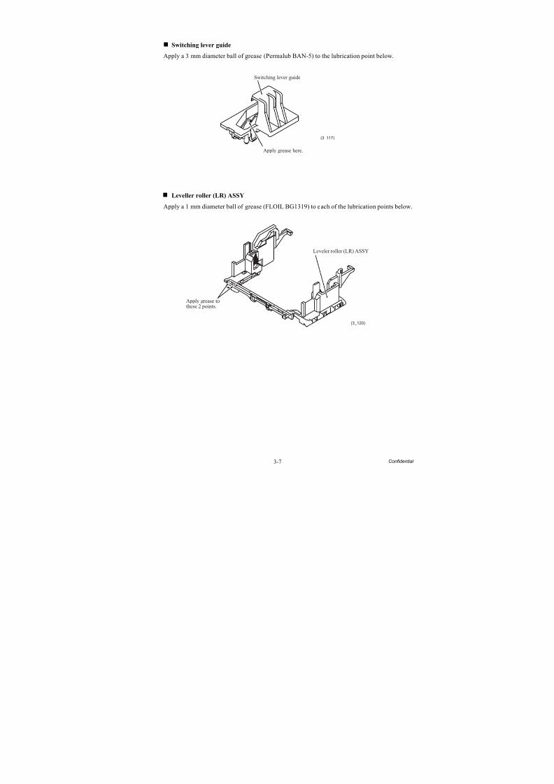
8/15/2019 Brother MFC 6510dw Sm
http://slidepdf.com/reader/full/brother-mfc-6510dw-sm 132/392
3-7 Confidential
Switching lever guide
Apply a 3 mm diameter ball of grease (Permalub BAN-5) to the lubrication point below.
Leveller roller (LR) ASSY
Apply a 1 mm diameter ball of grease (FLOIL BG1319) to each of the lubrication points below.
(3_117)
Apply grease here.
Switching lever guide
(3_120)
Apply grease tothese 2 points.
Leveler roller (LR) ASSY
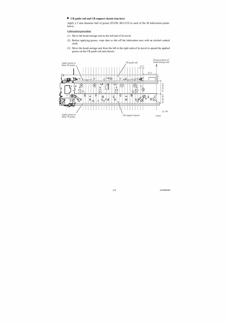
8/15/2019 Brother MFC 6510dw Sm
http://slidepdf.com/reader/full/brother-mfc-6510dw-sm 133/392
3-8 Confidential
CR guide rail and CR support chassis (top face)
Apply a 2 mm diameter ball of grease (FLOIL BG1319) to each of the 48 lubrication points below.
Lubrication procedure
(1) Move the head/carriage unit to the left end of its travel.(2) Before applying grease, wipe dust or dirt off the lubrication area with an alcohol soaked
cloth.
(3) Move the head/carriage unit from the left to the right ends of its travel to spread the appliedgrease on the CR guide rail and chassis.
(3_118)
(mm)
5 7 .
2 5
0 .
5
CR guide rail
12.7
57.1
CR support chassisApply grease tothese 24 points.
Apply grease tothese 24 points.
Home position ofhead/carriage unit
4 1 .
0 5
0 .
5
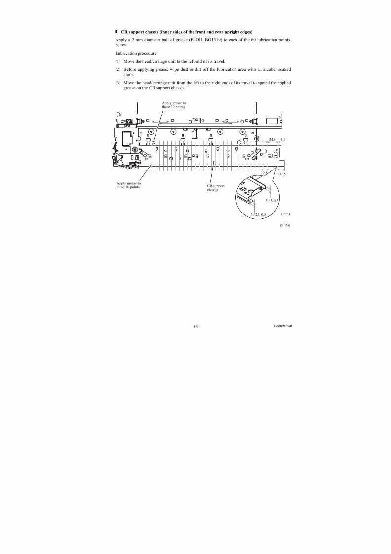
8/15/2019 Brother MFC 6510dw Sm
http://slidepdf.com/reader/full/brother-mfc-6510dw-sm 134/392
3-9 Confidential
CR support chassis (inner sides of the front and rear upright edges)
Apply a 2 mm diameter ball of grease (FLOIL BG1319) to each of the 60 lubrication points below.
Lubrication procedure
(1) Move the head/carriage unit to the left end of its travel.(2) Before applying grease, wipe dust or dirt off the lubrication area with an alcohol soaked
cloth.
(3) Move the head/carriage unit from the left to the right ends of its travel to spread the appliedgrease on the CR support chassis.
(3_119)
(mm)
CR supportchassis
5.65 0.5
Apply grease to
these 30 points
Apply grease tothese 30 points
34.8 4.1
10.8 13.15
5.625 0.5
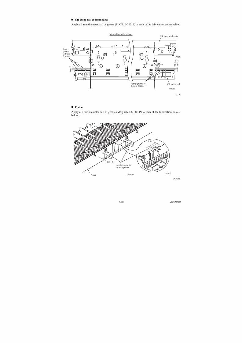
8/15/2019 Brother MFC 6510dw Sm
http://slidepdf.com/reader/full/brother-mfc-6510dw-sm 135/392
3-10 Confidential
CR guide rail (bottom face)
Apply a 1 mm diameter ball of grease (FLOIL BG1319) to each of the lubrication points below.
Platen
Apply a 1 mm diameter ball of grease (Molykote EM-30LP) to each of the lubrication points
below.
(3_116)
(mm)
3 .
0 -
4 .
0
CR support chassisViewed from the bottom
CR guide rail
Applygreaseto these3 points.
Apply grease tothese 3 points.
3 .
0 -
4 .
0
(Right)
0 .
5 -
1 .
0
35 1
50 130 1
20 1
40 1
22 1
(3_121)
(mm)
1.0-1.5
1.0-1.5
(Front)Platen
Apply grease tothese 3 points.
8/15/2019 Brother MFC 6510dw Sm
http://slidepdf.com/reader/full/brother-mfc-6510dw-sm 136/392
3-11 Confidential
T1 paper pull-in roller L
Apply a 1 mm diameter ball of grease (Molykote EM-30LP) to each of the lubrication points below.
Rib
(3_122)
Lower cover
T1 paper pull-inroller R
(Rear)
T1 paper pull-ingear
T1 paper pull-inroller LApply grease to
these 2 points.
8/15/2019 Brother MFC 6510dw Sm
http://slidepdf.com/reader/full/brother-mfc-6510dw-sm 137/392
3-12 Confidential
T2 paper pull-in roller L
Apply a 1 mm diameter ball of grease (Molykote EM-30LP) to each of the lubrication points below.
(3_064a)
T2 paper pull-inroller L
LT cover
Viewed from the rear
T2 paper pull-inroller R
T2 paper pull-ingear
Rib
Apply grease tothese 2 points.
8/15/2019 Brother MFC 6510dw Sm
http://slidepdf.com/reader/full/brother-mfc-6510dw-sm 138/392
3-13 Confidential
3.6 OVERVIEW OF GEARS
Maintenance unit
1
3 2
3
1
2
3
ASF SWITCHING GEAR A
ASF SWITCHING GEAR B
RESIN RETAINING RING
<Name of gears>
LX3419
LX3420
LX3421
8/15/2019 Brother MFC 6510dw Sm
http://slidepdf.com/reader/full/brother-mfc-6510dw-sm 139/392
3-14 Confidential
3.7 HARNESS ROUTING
1 Upper cover: ADF motor harness, CIS motor harness, Document detection/width & scanning position(first side) sensors harness, Document scanning position sensor harness (second side)* and ADF cover
switch harness
(3_021)
Route the bundle ofthe ADF motor harnessand its grounding wire,the CIS motor harness,and the loose groundingwire on this left side.
Cable guide
Cable guides
Cable guides
Ferrite core
Cable guide
ADF cover sensor harnessCIS motor harness
ADF motor harness
* For duplex scanning models
Document scanning positionsensor harness (second side)*
Document detection/width &scanning position (first side)sensors harness
Grounding wires
Route the bundle ofthe document detection/width & scanning position(first side) sensors harness,the document scanning positionsensor harness (second side)*,and the ADF cover sensorharness on this right side.
Upper cover
Boss
8/15/2019 Brother MFC 6510dw Sm
http://slidepdf.com/reader/full/brother-mfc-6510dw-sm 140/392
3-15 Confidential
*For duplex scanning models
2 CIS flat cable (black) for first side scanning, CIS flat cable (white) for second side scanning* and Flatcable support
(3_021_1)
Cable guides
CIS flat cable(white) forsecond sidescanning*
Flat cores
CIS flat cable (black)for first side scanning
Cable guide
Flat cable support
to be sandwiched
between the CIS
flat cables
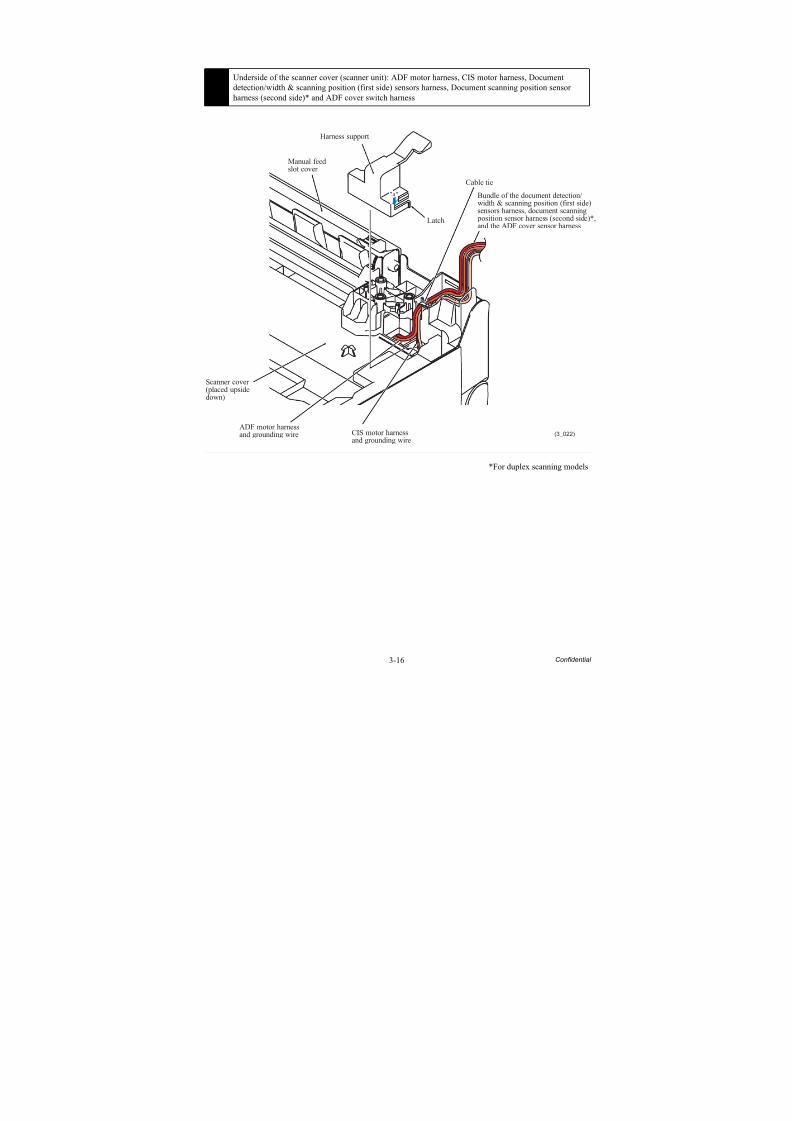
8/15/2019 Brother MFC 6510dw Sm
http://slidepdf.com/reader/full/brother-mfc-6510dw-sm 141/392
3-16 Confidential
*For duplex scanning models
3 Underside of the scanner cover (scanner unit): ADF motor harness, CIS motor harness, Documentdetection/width & scanning position (first side) sensors harness, Document scanning position sensorharness (second side)* and ADF cover switch harness
(3_022)CIS motor harnessand grounding wire
"a"
Harness support
Scanner cover(placed upsidedown)
ADF motor harnessand grounding wire
Cable tie
Latch
Manual feedslot cover
Bundle of the document detection/width & scanning position (first side)sensors harness, document scanning position sensor harness (second side)*,and the ADF cover sensor harness
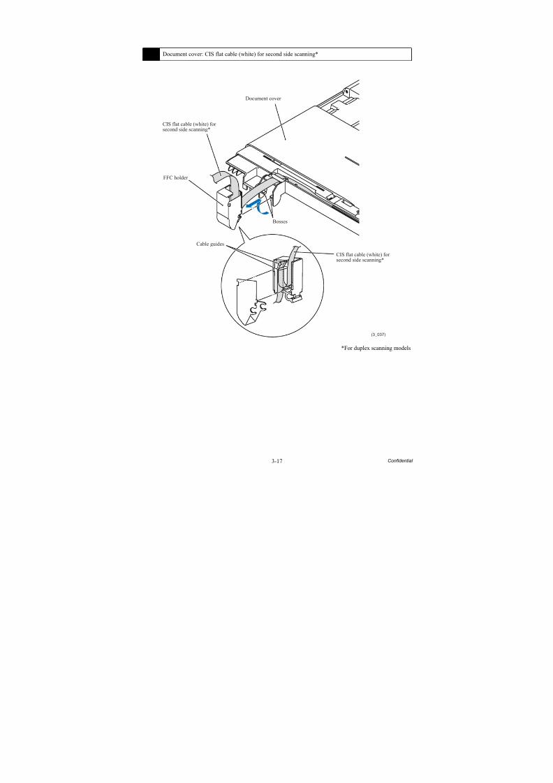
8/15/2019 Brother MFC 6510dw Sm
http://slidepdf.com/reader/full/brother-mfc-6510dw-sm 142/392
3-17 Confidential
*For duplex scanning models
4 Document cover: CIS flat cable (white) for second side scanning*
(3_037)
Bosses
Cable guides
FFC holder
CIS flat cable (white) forsecond side scanning*
Document cover
CIS flat cable (white) forsecond side scanning*
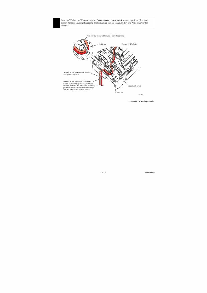
8/15/2019 Brother MFC 6510dw Sm
http://slidepdf.com/reader/full/brother-mfc-6510dw-sm 143/392
3-18 Confidential
*For duplex scanning models
5 Lower ADF chute: ADF motor harness, Document detection/width & scanning position (first side)sensors harness, Document scanning position sensor harness (second side)* and ADF cover switchharness
(3_046)
Cut off the excess of the cable tie with nippers.
Cable tie
Bundle of the ADF motor harnessand grounding wire
Bundle of the document detection/width & scanning position (first side)sensors harness, the document scanning position sensor harness (second side)*,and the ADF cover sensor harness
Document cover
Lower ADF chute
Cable tie
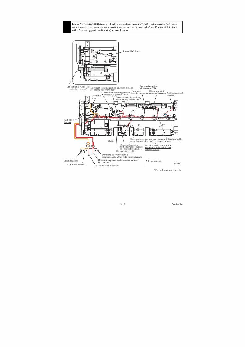
8/15/2019 Brother MFC 6510dw Sm
http://slidepdf.com/reader/full/brother-mfc-6510dw-sm 144/392
3-19 Confidential
6 Lower ADF chute: CIS flat cable (white) for second side scanning*, ADF motor harness, ADF coverswitch harness, Document scanning position sensor harness (second side)* and Document detection/width & scanning position (first side) sensors harness
(3_045)
ADF motorharness
Grounding wire
ADF motor harness ADF cover switch harness
Document feed roller
(Left)
(Document scanning position detection actuator (for first side scanning))
Document scanning positionsensor harness (first side)
Document detection/widthsensor harness
ADF cover switchharness
(Document widthdetection actuator)
Document detection/width sensor PCB
(Documentdetection actuator)
Groundingwire
* For duplex scanning models
Lower ADF chute
CIS flat cable (white) forsecond side scanning*
Document detection/width &scanning position (first side) sensors harness
Document detection/width &scanning position (first side)sensors harness
Document scanning position sensor harness(second side)*
Document scanning positionsensor harness (second side)*
(Document scanning position detection actuator(for second side scanning))*
Document scanning positionsensor PCB (second side)*
ADF harness unit

8/15/2019 Brother MFC 6510dw Sm
http://slidepdf.com/reader/full/brother-mfc-6510dw-sm 145/392
3-20 Confidential
7 Upper cover: Battery harness
(3_056)
Upper cover Cable guidesSpeaker springSpeaker
Main PCB Backup batteryCable guide
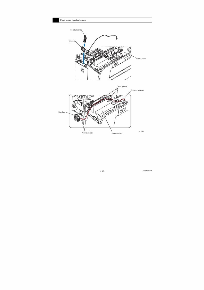
8/15/2019 Brother MFC 6510dw Sm
http://slidepdf.com/reader/full/brother-mfc-6510dw-sm 146/392
3-21 Confidential
8 Upper cover: Speaker harness
(3_054)
Speaker spring
Speaker
Upper cover
Speaker
Upper cover
Cable guides
Cable guides
Speaker harness
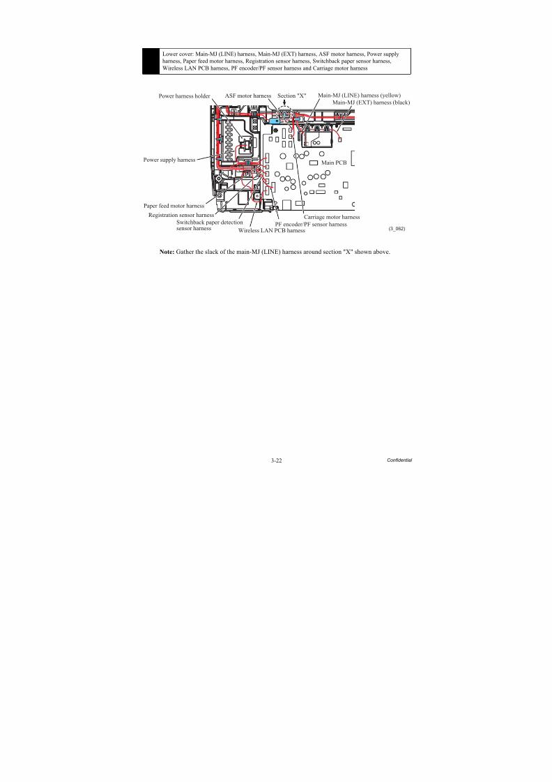
8/15/2019 Brother MFC 6510dw Sm
http://slidepdf.com/reader/full/brother-mfc-6510dw-sm 147/392
3-22 Confidential
Note: Gather the slack of the main-MJ (LINE) harness around section "X" shown above.
9 Lower cover: Main-MJ (LINE) harness, Main-MJ (EXT) harness, ASF motor harness, Power supplyharness, Paper feed motor harness, Registration sensor harness, Switchback paper sensor harness,Wireless LAN PCB harness, PF encoder/PF sensor harness and Carriage motor harness
(3_062)
ASF motor harness
Power supply harness
Paper feed motor harness
Registration sensor harness
Switchback paper detectionsensor harness Wireless LAN PCB harness
PF encoder/PF sensor harness
Carriage motor harness
Main PCB
Main-MJ (EXT) harness (black)
Main-MJ (LINE) harness (yellow)Power harness holder Section "X"
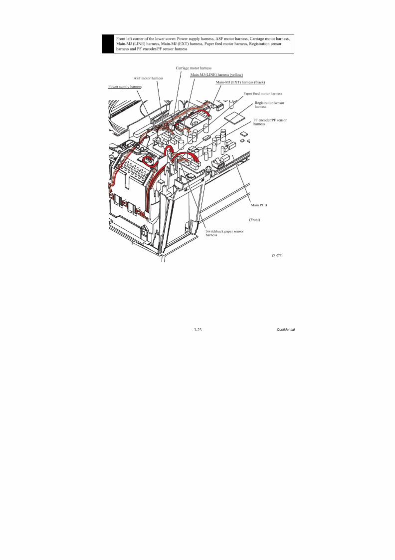
8/15/2019 Brother MFC 6510dw Sm
http://slidepdf.com/reader/full/brother-mfc-6510dw-sm 148/392
3-23 Confidential
10 Front left corner of the lower cover: Power supply harness, ASF motor harness, Carriage motor harness,Main-MJ (LINE) harness, Main-MJ (EXT) harness, Paper feed motor harness, Registration sensorharness and PF encoder/PF sensor harness
(3_071)
Switchback paper sensorharness
Power supply harness
ASF motor harness
Carriage motor harness
Paper feed motor harness
PF encoder/PF sensor
harness
Main PCB
Main-MJ (EXT) harness (black)
Main-MJ (LINE) harness (yellow)
Registration sensor harness
(Front)
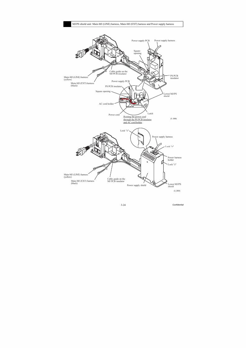
8/15/2019 Brother MFC 6510dw Sm
http://slidepdf.com/reader/full/brother-mfc-6510dw-sm 149/392
3-24 Confidential
11 MJ/PS shield unit: Main-MJ (LINE) harness, Main-MJ (EXT) harness and Power supply harness
(3_068)
Power cord
Power supply harness
PS PCB insulator
PS PCB
insulator Power supply PCB
Power supply PCB
Squareopening
Lower MJ/PSshield
Main-MJ (LINE) harness(yellow)
Main-MJ (EXT) harness(black)
Cable guide on theMJ PCB insulator
AC cord holder
Routing the power cordthrough the PS PCB insulatorand AC cord holder
Square opening
Latch
(3_069)
Power supply harness
Lower MJ/PSshield
Main-MJ (LINE) harness(yellow)
Main-MJ (EXT) harness(black)
Power supply shield
Lock "z"
Lock "z"
Lock "z"
Cable guide on theMJ PCB insulator
Power harnessholder
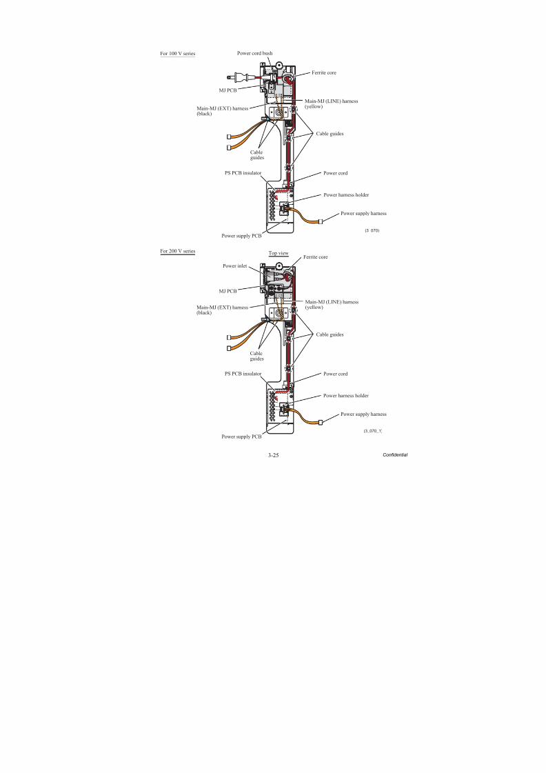
8/15/2019 Brother MFC 6510dw Sm
http://slidepdf.com/reader/full/brother-mfc-6510dw-sm 150/392
3-25 Confidential
(3_070)
Power cord bush
MJ PCB
Main-MJ (EXT) harness(black)
Main-MJ (LINE) harness(yellow)
Cableguides
PS PCB insulator
Power supply PCB
Power supply harness
Power cord
Cable guides
Ferrite core
Power harness holder
For 100 V series
(3_070_1)
MJ PCB
Cableguides
PS PCB insulator
Power supply PCB
Power supply harness
Power cord
Power harness holder
Cable guides
Ferrite coreTop viewFor 200 V series
Power inlet
Main-MJ (EXT) harness(black)
Main-MJ (LINE) harness(yellow)
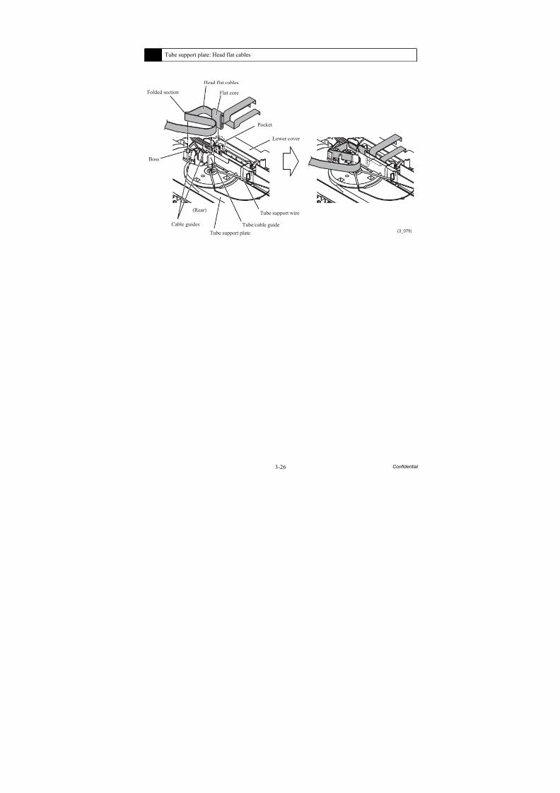
8/15/2019 Brother MFC 6510dw Sm
http://slidepdf.com/reader/full/brother-mfc-6510dw-sm 151/392
3-26 Confidential
12 Tube support plate: Head flat cables
(3_079)
Head flat cables
Flat coreFolded section
Boss
Cable guides
(Rear)
Tube support plate
Tube/cable guide
Tube support wire
Lower cover
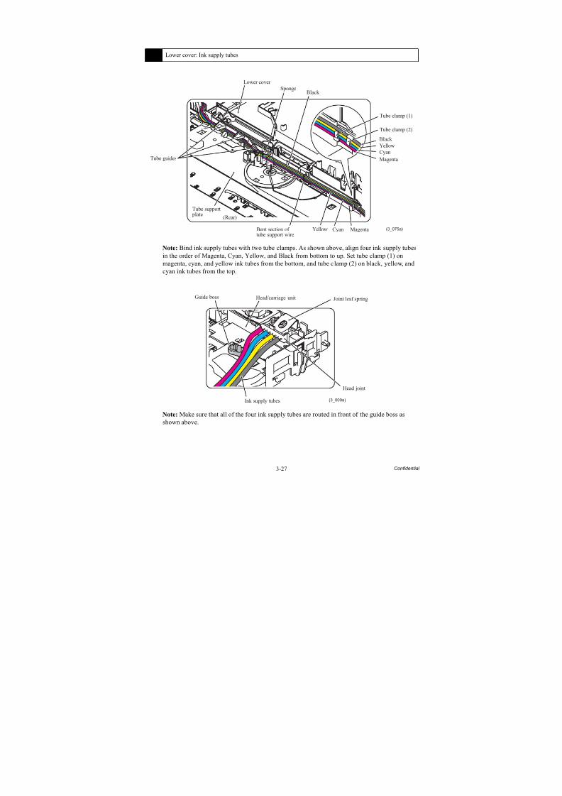
8/15/2019 Brother MFC 6510dw Sm
http://slidepdf.com/reader/full/brother-mfc-6510dw-sm 152/392
3-27 Confidential
Note: Bind ink supply tubes with two tube clamps. As shown above, align four ink supply tubesin the order of Magenta, Cyan, Yellow, and Black from bottom to up. Set tube clamp (1) onmagenta, cyan, and yellow ink tubes from the bottom, and tube clamp (2) on black, yellow, andcyan ink tubes from the top.
Note: Make sure that all of the four ink supply tubes are routed in front of the guide boss asshown above.
13 Lower cover: Ink supply tubes
(3_075a)
Lower cover
Tube guides
Tube support plate
(Rear)
Bent section oftube support wire
Yellow Cyan Magenta
Black
Yellow
Cyan
Magenta
Tube clamp (1)
Black Sponge
Tube clamp (2)
Joint leaf spring
(3_009a)
Head joint
Head/carriage unit
Ink supply tubes
Guide boss
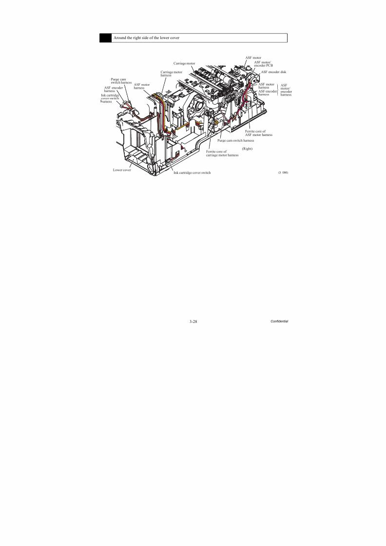
8/15/2019 Brother MFC 6510dw Sm
http://slidepdf.com/reader/full/brother-mfc-6510dw-sm 153/392
3-28 Confidential
14 Around the right side of the lower cover
(3_086)
Carriage motor
Carriage motorharness
ASF motorharness
Purge camswitch harness
ASF encoderharness
Ink cartridgecover switcharness
Lower cover Ink cartridge cover switch
Ferrite core ofcarriage motor harness
(Right)
Purge cam switch harness
Ferrite core ofASF motor harness
ASF encoderharness
ASF motorharness
ASFmotor/encoderharness
ASF encoder disk
ASF motor/encoder PCB
ASF motor
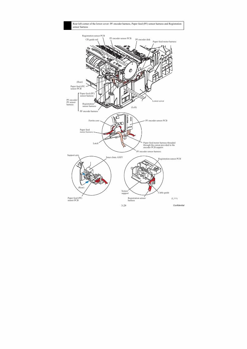
8/15/2019 Brother MFC 6510dw Sm
http://slidepdf.com/reader/full/brother-mfc-6510dw-sm 154/392
3-29 Confidential
15 Rear left corner of the lower cover: PF encoder harness, Paper feed (PF) sensor harness and Registrationsensor harness
(3_111)
Paper feed motor harnessPF encoder disk CR guide rail
Registrationsensor harness
(Rear)
(Rear)
PF encoder harness
PF encoder/PF sensorharness
(Left)
Lower cover
Cable guide
Paper feed (PF)sensor harness
Paper feed (PF)sensor PCB
Registration sensor PCB
Sensorsupport
Registration sensorharness
Inner chute ASSYSupport arm
PF encoder sensor PCBFerrite core
Paper feedmotor harness
Latch
PF encoder sensor harness
Paper feed motor harness threadedthrough the cutout provided in theencoder PCB support
PF encoder sensor PCB
Registration sensor PCB
Paper feed (PF)sensor PCB
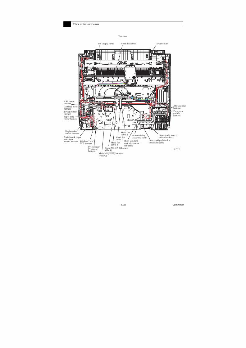
8/15/2019 Brother MFC 6510dw Sm
http://slidepdf.com/reader/full/brother-mfc-6510dw-sm 155/392
3-30 Confidential
16 Whole of the lower cover
(3_114)
ASF motorharness
Main PCB
PF encoder/PF sensorharness
Switchback paperdetectionsensor harness
Registrationsensor harness
Paper feedmotor harness
Carriage motorharness
ASF encoderharness
Purge camswitchharness
Ink cartridge coverswitch harness
Top view
Lower cover Head flat cablesInk supply tubes
Power supplyharness
Wireless LANPCB harness
Main-MJ (LINE) harness
(yellow)
Main-MJ (EXT) harness(black)
Head flatcable 3
Head flatcable 2
Head flatcable 1
High-yield inkcartridge sensorflat cable
Ink remainingsensor flat cable
Ink cartridge detectionsensor flat cable
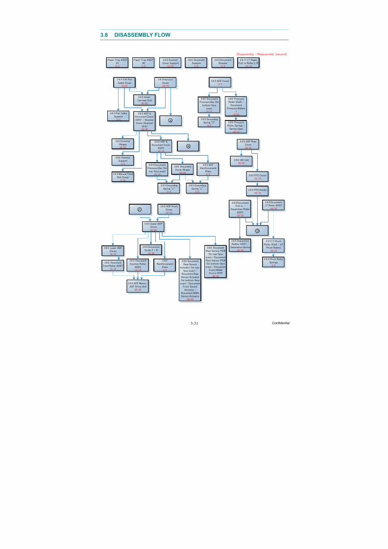
8/15/2019 Brother MFC 6510dw Sm
http://slidepdf.com/reader/full/brother-mfc-6510dw-sm 156/392
8/15/2019 Brother MFC 6510dw Sm
http://slidepdf.com/reader/full/brother-mfc-6510dw-sm 157/392
3-32 Confidential
Earth
spring
5/5
Maintenance unit
15/15
15/15
Star
wheel holder
20/30
Inner
chute ASSY
10/10
20/20
15/15
1/10
A
B
E
E
D
D
8/15/2019 Brother MFC 6510dw Sm
http://slidepdf.com/reader/full/brother-mfc-6510dw-sm 158/392
3-33 Confidential
3.9 DISASSEMBLY PROCEDURE
3.9.1 Preparation
[ 1 ] Transferring Received FAX Data
When the machine at the user site requires to be repaired, unplugging the power cord from theelectrical outlet for sending the machine for repair will lose received FAX data if left in themachine.
To prevent such data loss, the service personnel should instruct end users (e.g., by telephone) totransfer data to another facsimile machine or PC using the procedure below.
NOTE: The number of files that can be transferred at a time is 99. To transfer 100 files or more,carry out the following procedure more than one time.
TIP: If there are both color and monochrome data in a file to be transferred, the monochromedata will be transferred first. If the receiver machine does not support the color function, the
sender machine cannot transfer color data, resulting in an error.
Transferring faxes to another fax machine
Operating Procedure
(1) Press the Stop/Exit key to interrupt the error (if displayed) temporarily.
(2) Press the Menu key.
(3) Press the or key to choose "Service."
(4) Press the OK key.
TIP: For models with touch panel, you may press the Service key.(5) Press the or key to choose "Data Transfer."
(6) Press the OK key.
TIP: For models with touch panel, you may press the Data Transfer key.
(7) Press the or key to choose "Fax Transfer."
(8) Press the OK key.
TIP: For models with touch panel, you may press the Fax Transfer key.
(9) If "No Data" appears on the LCD, there are no faxes left in the machine’s memory. Then press the Stop/Exit key.
If a fax number entry screen appears, there are faxes in the machine’s memory. Then enter the fax number to which faxes will be forwarded
(10)Press the Black Start key.
8/15/2019 Brother MFC 6510dw Sm
http://slidepdf.com/reader/full/brother-mfc-6510dw-sm 159/392
3-34 Confidential
Transferring faxes to a PC
Operating Procedure
The following procedure uses the fax machine and your PC.
(1) Press the Stop/Exit key to interrupt the error (if displayed) temporarily.
(2) Press the Menu key.
(3) Press the or key to choose "Fax."
(4) Press the OK key.
TIP: For models with touch panel, you may press the Fax key.
(5) Press the or key to choose "Setup Receive."
(6) Press the OK key.
TIP: For models with touch panel, you may press the Setup Receive key.
(7) Press the or key to choose "Memory Receive."
(8) Press the OK key.
TIP: For models with touch panel, you may press the Memory Receive key.
(9) Press the or key to choose "PC Fax Receive."
(10)Press the OK key.
TIP: For models with touch panel, you may press the PC Fax Receive key.
(11) If the "Run PC-Fax on your computer." appears on the LCD, press the OK key.
(12)Click Start | All Programs | Brother | MFC-XXXX | PC-FAX Receiving | Receive.
Wait for the PC-Fax Receiving dialog box to appear. Confirm the message and click OK .
The PC-FAX icon appears in your PC task tray.
(13)Press the or key to choose "<USB>" or the PC you run in step (12).
(14)Press the OK key.
TIP: For models with touch panel, you may press the <USB> key.
(15)Press or key to choose "Backup Print: On" or "Backup Print: Off."
(16)Press the OK key.
TIP: For models with touch panel, you may press the "Backup Print: On" or "BackupPrint: Off."
NOTE: Choosing "Backup Print: On" prints the fax.
(17)Press the Stop/Exit key.

8/15/2019 Brother MFC 6510dw Sm
http://slidepdf.com/reader/full/brother-mfc-6510dw-sm 160/392
3-35 Confidential
[ 2 ] Backing up Machine Information
Before starting repair, the service personnel should back up the following machine informationand user setting information into an external memory (memory card or USB flash memory).
- Machine information (Preset values, counter values, error information, machinespecifications data, etc.)
- User setting information (telephone directory, password, station ID, transfer information,telephone area code, user settings, etc.)
- Other data (Received fax data, ICM/OGM data, etc.)
Note that the following information cannot be backed up.
- Serial number of the machine
- MAC address
- Call and caller ID records
- Activity report- Fax data sent (Delayed-timer sent data, redialed sent data, and polled sent data)
Operating Procedure
Refer to Chapter 5, Section 5.1.4.11 "Backup of Machine Information (Function code 46)(User-accessible)."
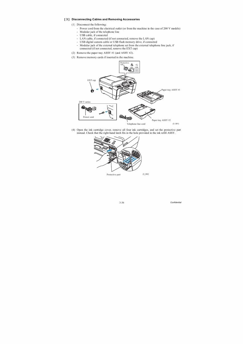
8/15/2019 Brother MFC 6510dw Sm
http://slidepdf.com/reader/full/brother-mfc-6510dw-sm 161/392
3-36 Confidential
[ 3 ] Disconnecting Cables and Removing Accessories
(1) Disconnect the following:
- Power cord from the electrical outlet (or from the machine in the case of 200 V models)- Modular jack of the telephone line- USB cable, if connected
- LAN cable, if connected (if not connected, remove the LAN cap)- USB digital camera cable or USB flash memory drive, if connected- Modular jack of the external telephone set from the external telephone line jack, if
connected (if not connected, remove the EXT cap)
(2) Remove the paper tray ASSY #1 (and ASSY #2).
(3) Remove memory cards if inserted in the machine.
(4) Open the ink cartridge cover, remove all four ink cartridges, and set the protective partinstead. Check that the right-hand latch fits in the hole provided in the ink refill ASSY.
Telephone line cord (3_001)
EXT cap
Paper tray ASSY #1
Paper tray ASSY #2
Protectivecap
Power cord
200 V series
LAN USB
Protective part (3_002)
8/15/2019 Brother MFC 6510dw Sm
http://slidepdf.com/reader/full/brother-mfc-6510dw-sm 162/392
3-37 Confidential
3.9.2 Head/Carriage Unit
During disassembly jobs, except when removing the ink refill ASSY or engine unit (includingthe maintenance unit), leave the head/carriage unit in the machine.
Before removing the head/carriage unit, ink refill ASSY or engine unit, you need to remove allfour ink cartridges and set the protective part instead (see the previous page). Be sure to insertthe protective part into place to prevent ink remaining in the ink supply tubes from leaking andthe machine from getting stained with leaked ink. (Check that the right-hand latch fits in thehole provided in the ink refill ASSY.)
Note: When replacing the head/carriage unit, put on a grounding wrist band and perform the jobon a static mat. Also take care not to touch the conductor sections on the flat cables.
Note: During the removal or installation job for the head/carriage unit, take care not tocontaminate the CR encoder strip or PF encoder disk with ink or grease.
Note: If you replace the head/carriage unit, also replace the ink cartridges. This is becausesufficient ink volume is necessary for refilling the ink supply tubes after replacement of the
head/carriage unit.
(1) Plug the power cord into an electrical outlet.
(2) Open the scanner cover (scanner unit) until it locks.
The "Cover is Open." message appears on the LCD.
(3) Hold down the Stop/Exit key to move the head/carriage unit to the center of its travel.
(3_003)
Upper cover
ADF & document cover ASSY
Scanner cover(Scanner unit)
Scanner cover support
Stop/Exit key
Lower cover Head/carriage unit
LT cover (For models with paper tray #2)
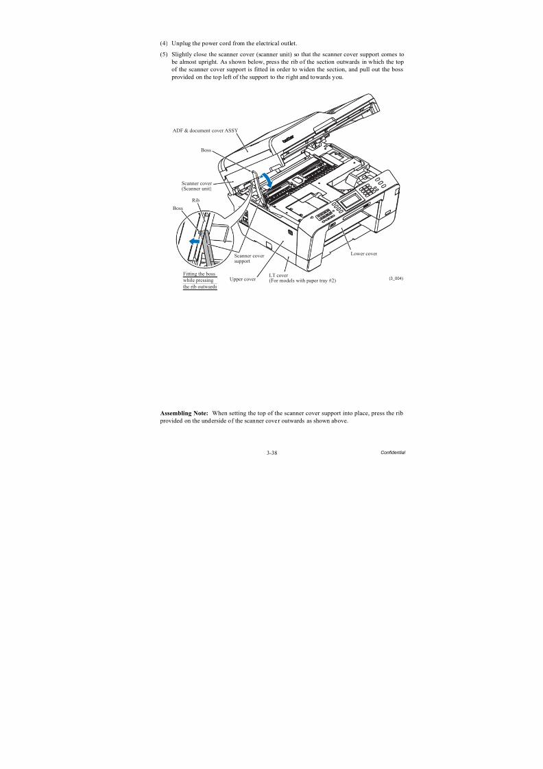
8/15/2019 Brother MFC 6510dw Sm
http://slidepdf.com/reader/full/brother-mfc-6510dw-sm 163/392
3-38 Confidential
(4) Unplug the power cord from the electrical outlet.
(5) Slightly close the scanner cover (scanner unit) so that the scanner cover support comes to be almost upright. As shown below, press the rib of the section outwards in which the topof the scanner cover support is fitted in order to widen the section, and pull out the boss provided on the top left of the support to the right and towards you.
Assembling Note: When setting the top of the scanner cover support into place, press the rib provided on the underside of the scanner cover outwards as shown above.
(3_004)
Boss
Boss
Upper cover
ADF & document cover ASSY
Scanner cover(Scanner unit)
Scanner coversupport
Lower cover
LT cover (For models with paper tray #2)
Fitting the bosswhile pressingthe rib outwards
Rib
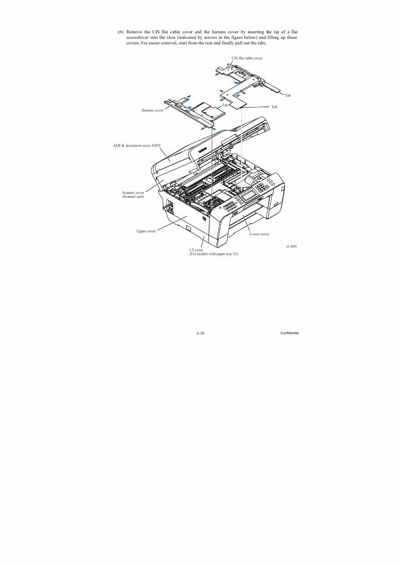
8/15/2019 Brother MFC 6510dw Sm
http://slidepdf.com/reader/full/brother-mfc-6510dw-sm 164/392
3-39 Confidential
(6) Remove the CIS flat cable cover and the harness cover by inserting the tip of a flatscrewdriver into the slots (indicated by arrows in the figure below) and lifting up thosecovers. For easier removal, start from the rear and finally pull out the tabs.
Upper cover
ADF & document cover ASSY
Scanner cover(Scanner unit)
Harness cover Tab
CIS flat cable cover
Tab
Tab
(3_005)
Lower cover
LT cover
(For models with paper tray #2)
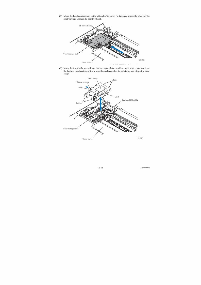
8/15/2019 Brother MFC 6510dw Sm
http://slidepdf.com/reader/full/brother-mfc-6510dw-sm 165/392
3-40 Confidential
(7) Move the head/carriage unit to the left end of its travel (to the place where the whole of thehead/carriage unit can be seen) by hand.
(8) Insert the tip of a flat screwdriver into the square hole provided in the head cover to releasethe latch in the direction of the arrow, then release other three latches and lift up the headcover.
(3_006)
ead/carriage unit
Upper cover
PF encoder disk
Tabs
(3_007)
Head cover
Square opening
Latch
Latches
Head/carriage unit
Upper cover
Carriage PCB ASSY
Latch
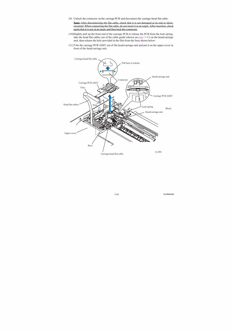
8/15/2019 Brother MFC 6510dw Sm
http://slidepdf.com/reader/full/brother-mfc-6510dw-sm 166/392
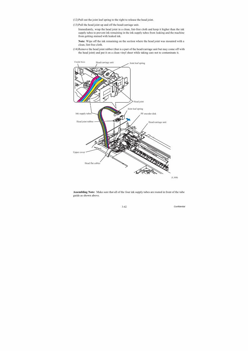
8/15/2019 Brother MFC 6510dw Sm
http://slidepdf.com/reader/full/brother-mfc-6510dw-sm 167/392
3-42 Confidential
(12)Pull out the joint leaf spring to the right to release the head joint.
(13)Pull the head joint up and off the head/carriage unit.
Immediately, wrap the head joint in a clean, lint-free cloth and keep it higher than the ink supply tubes to prevent ink remaining in the ink supply tubes from leaking and the machinefrom getting stained with leaked ink.
Note: Wipe off the ink remaining on the section where the head joint was mounted with aclean, lint-free cloth.
(14)Remove the head joint rubber (that is a part of the head/carriage unit but may come off withthe head joint) and put it on a clean vinyl sheet while taking care not to contaminate it.
Assembling Note: Make sure that all of the four ink supply tubes are routed in front of the tube
guide as shown above.
Joint leaf spring
Joint leaf spring
(3_009)
Head joint
Upper cover
Head flat cables
Head/carriage unit
Head/carriage unit
PF encoder disk
Head joint rubber
Ink supply tubes
Guide boss
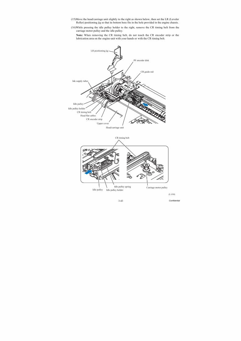
8/15/2019 Brother MFC 6510dw Sm
http://slidepdf.com/reader/full/brother-mfc-6510dw-sm 168/392
3-43 Confidential
(15)Move the head/carriage unit slightly to the right as shown below, then set the LR (Leveler Roller) positioning jig so that its bottom boss fits in the hole provided in the engine chassis.
(16)While pressing the idle pulley holder to the right, remove the CR timing belt from thecarriage motor pulley and the idle pulley.
Note: When removing the CR timing belt, do not touch the CR encoder strip or the
lubrication area on the engine unit with your hands or with the CR timing belt.
(3_010)
LR positioning jig
Idle pulley
Idle pulley holder
CR timing belt
CR encoder strip
Upper cover
Head/carriage unit
CR guide rail
PF encoder disk
Carriage motor pulley
CR timing belt
Idle pulley Idle pulley holder
Idle pulley spring
Ink supply tubes
Head flat cables
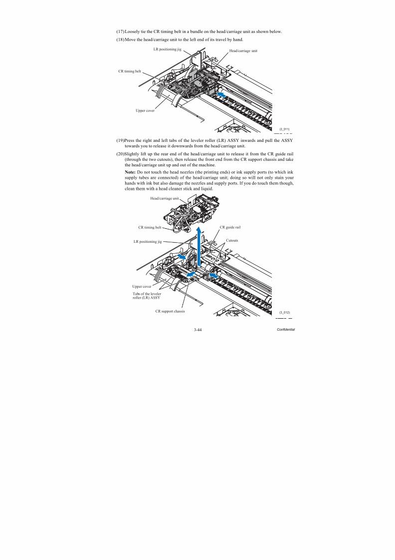
8/15/2019 Brother MFC 6510dw Sm
http://slidepdf.com/reader/full/brother-mfc-6510dw-sm 169/392
3-44 Confidential
(17)Loosely tie the CR timing belt in a bundle on the head/carriage unit as shown below.
(18)Move the head/carriage unit to the left end of its travel by hand.
(19)Press the right and left tabs of the leveler roller (LR) ASSY inwards and pull the ASSYtowards you to release it downwards from the head/carriage unit.
(20)Slightly lift up the rear end of the head/carriage unit to release it from the CR guide rail(through the two cutouts), then release the front end from the CR support chassis and takethe head/carriage unit up and out of the machine.
Note: Do not touch the head nozzles (the printing ends) or ink supply ports (to which ink supply tubes are connected) of the head/carriage unit; doing so will not only stain your hands with ink but also damage the nozzles and supply ports. If you do touch them though,
clean them with a head cleaner stick and liquid.
(3_011)
LR positioning jig
CR timing belt
Upper cover
Head/carriage unit
CR guide rail
(3_012)
Head/carriage unit
CR timing belt
Upper cover
Tabs of the levelerroller (LR) ASSY
CR support chassis
CutoutsLR positioning jig
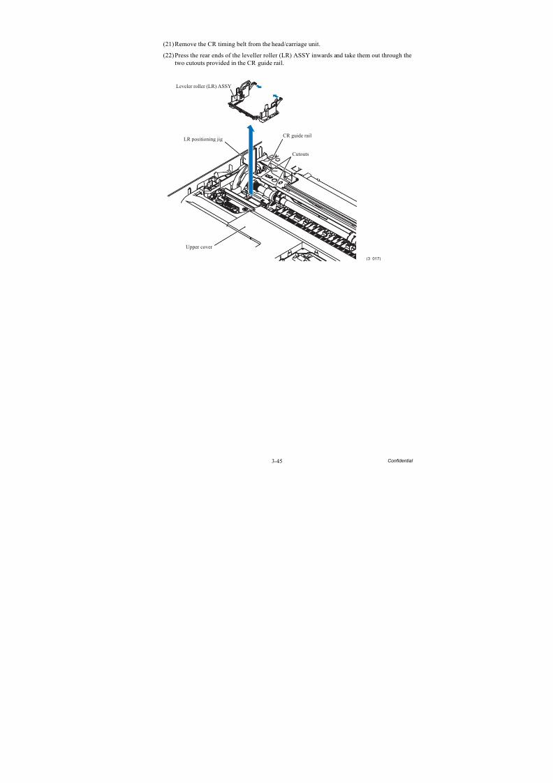
8/15/2019 Brother MFC 6510dw Sm
http://slidepdf.com/reader/full/brother-mfc-6510dw-sm 170/392
3-45 Confidential
(21)Remove the CR timing belt from the head/carriage unit.
(22)Press the rear ends of the leveller roller (LR) ASSY inwards and take them out through thetwo cutouts provided in the CR guide rail.
CR guide rail
(3_017)
Upper cover
Cutouts
Leveler roller (LR) ASSY
LR positioning jig
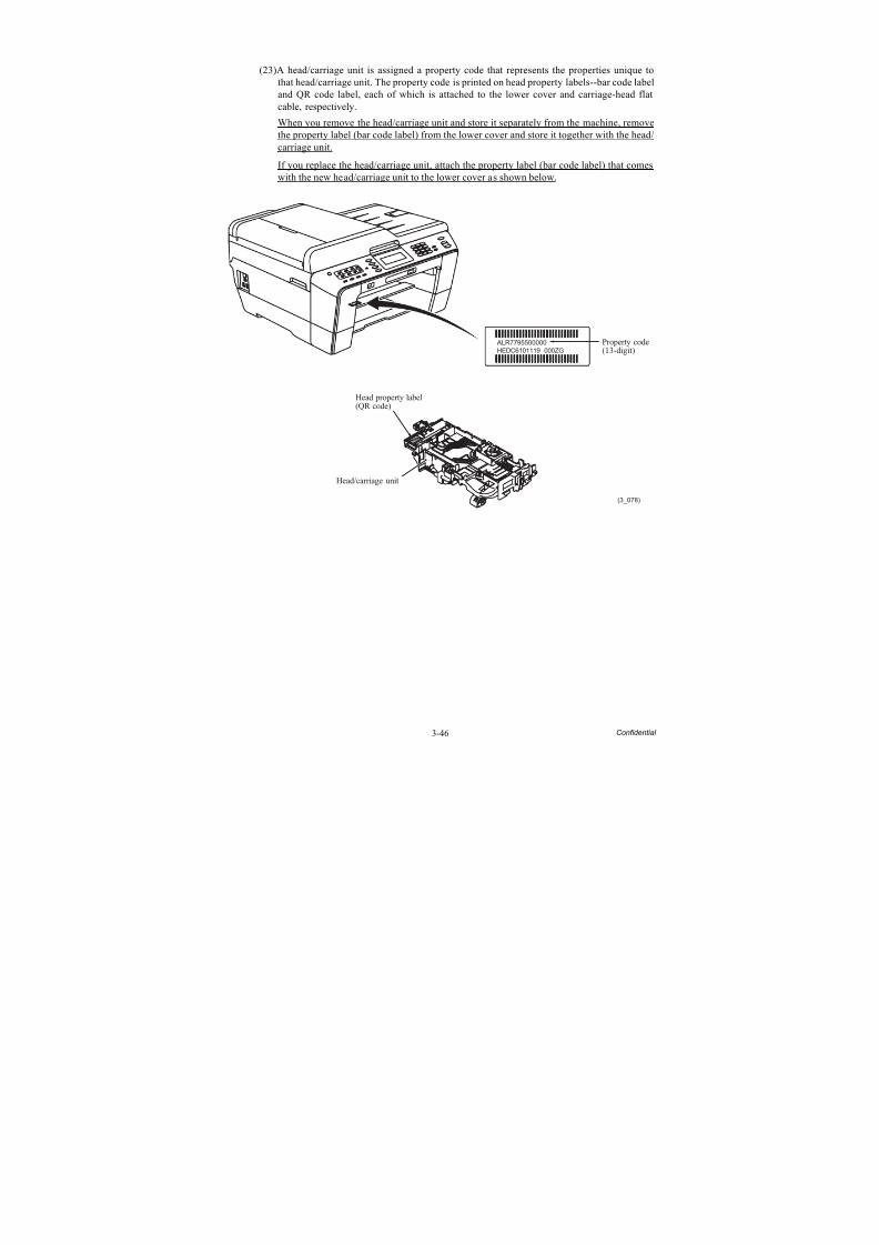
8/15/2019 Brother MFC 6510dw Sm
http://slidepdf.com/reader/full/brother-mfc-6510dw-sm 171/392
3-46 Confidential
(23)A head/carriage unit is assigned a property code that represents the properties unique tothat head/carriage unit. The property code is printed on head property labels--bar code labeland QR code label, each of which is attached to the lower cover and carriage-head flatcable, respectively.
When you remove the head/carriage unit and store it separately from the machine, remove
the property label (bar code label) from the lower cover and store it together with the head/carriage unit.
If you replace the head/carriage unit, attach the property label (bar code label) that comeswith the new head/carriage unit to the lower cover as shown below.
ALR7795500000
HEDC6101119 000ZG
(3_078)
Head property label(QR code)
Head/carriage unit
Property code(13-digit)
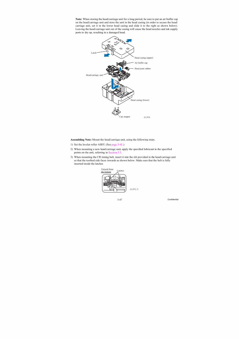
8/15/2019 Brother MFC 6510dw Sm
http://slidepdf.com/reader/full/brother-mfc-6510dw-sm 172/392
3-47 Confidential
Note: When storing the head/carriage unit for a long period, be sure to put an air buffer capon the head/carriage unit and store the unit in the head casing (in order to secure the head/carriage unit, set it in the lower head casing and slide it to the right as shown below).Leaving the head/carriage unit out of the casing will cause the head nozzles and ink supply ports to dry up, resulting in a damaged head.
Assembling Note: Mount the head/carriage unit, using the following steps.
1) Set the leveler roller ASSY. (See page 3-45.)
2) When mounting a new head/carriage unit, apply the specified lubricant to the specified
points on the unit, referring to Section 3.5.3) When mounting the CR timing belt, insert it into the slit provided in the head/carriage unit
so that the toothed side faces inwards as shown below. Make sure that the belt is fullyinserted inside the latches
Head joint rubber
(3_013)
Head/carriage unit
Latch
Head casing (lower)
Cap stopper
Air buffer cap
Head casing (upper)
LatchesViewed fromthe bottom
(3_013_1)
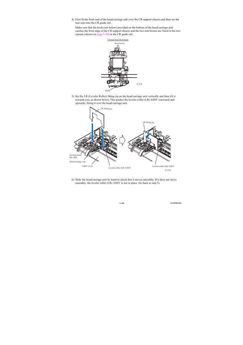
8/15/2019 Brother MFC 6510dw Sm
http://slidepdf.com/reader/full/brother-mfc-6510dw-sm 173/392
3-48 Confidential
4) First fit the front end of the head/carriage unit over the CR support chassis and then set therear end onto the CR guide rail.
Make sure that the hook (see below) provided on the bottom of the head/carriage unitcatches the front edge of the CR support chassis and the two rear bosses are fitted in the twocutouts (shown on page 3-45) in the CR guide rail.
5) Set the LR (Leveler Roller) fitting jig on the head/carriage unit vertically and then tilt ittowards you, as shown below. This pushes the leveler roller (LR) ASSY rearwards andupwards, fitting it over the head/carriage unit.
6) Slide the head/carriage unit by hand to check that it moves smoothly. If it does not movesmoothly, the leveler roller (LR) ASSY is not in place. Go back to step 5).
Viewed from the bottom
Hook
(3_015)
Rear bosses
(3_018)
Leveler roller (LR) ASSYLeveler roller (LR) ASSY
LR fitting jig
Carriage-headflat cable
Head/carriage unit
Upper cover
LR fitting jig
8/15/2019 Brother MFC 6510dw Sm
http://slidepdf.com/reader/full/brother-mfc-6510dw-sm 174/392
3-49 Confidential
7) Remove the LR fitting jig and LR positioning jig.
8) Untie the CR timing belt loosely tied. First, at the left end, set the belt on the idle pulley. Next, press the idle pulley holder to the right and at the right end, set the belt on the carriagemotor pulley. (See page 3-43.)
9) Slide the head/carriage unit by hand to check that it smoothly moves to the right and left
ends of its travel.10) Set the head joint rubber on the head/carriage unit and secure the head joint to the head/
carriage unit with the joint leaf spring. (See page 3-42.)
11) Mount the carriage PCB ASSY on the head/carriage unit, route the head flat cables throughthe cable guide, and fit the hole provided in the film over the boss on the head/carriage unitas shown below.
Make sure that the head/carriage unit is secured with the lock spring.
12) Connect the carriage-head flat cable to the connector on the carriage PCB and then lock theconnector.
13) Set the head cover into place.
14) If a new head/carriage unit is mounted, apply the specified lubricant to the specified pointson the sliding surface of the CR guide rail and CR support chassis, referring to Section 3.5.
15) Check that the CR encoder strip and PF encoder disk are free of grease and ink. If they arestained with grease or ink, replace them.
16) Slide the head/carriage unit by hand to check that it smoothly moves to the right and leftends of its travel. At the same time, check that the ink supply tubes and head flat cables arenot twisted.
17) If a new head/carriage unit is mounted, make adjustments specified in Chapter 4, Section
4.1.
(3_016)
Carriage PCB ASSY
Lock spring
Carriage-head flat cable
Cable guide
Boss
Film
HoleHead flat cables
8/15/2019 Brother MFC 6510dw Sm
http://slidepdf.com/reader/full/brother-mfc-6510dw-sm 175/392
3-50 Confidential
3.9.3 Scanner Cover (Scanner Unit) and Scanner Cover Support
The scanner cover should be removed together with the ADF & document cover ASSY whoseremoval procedure is given in Section 3.9.4. The disassembly of the ADF & document cover ASSY is detailed in Section 3.9.5.
(1) Disconnect the white CIS flat cable (for second side scanning)* from the main PCB andremove the two flat cores from the cable. *For duplex scanning models
(2) Disconnect the black CIS flat cable (for first side scanning) from the main PCB and pull itto the rear through the two flat cores* (single flat core for the simplex scanning models),and then release it from the cable guides. Unlatch the flat cores and take them out of theupper cover.
Note: After disconnecting the flat cable(s), check that each cable is not damaged at its endor short-circuited. When connecting the flat cable(s), do not insert it at an angle. After insertion, check again that it is not at an angle.
(3) Release the two CIS flat cables from the cable guides together with the flat cable support.
(4) Release the two grounding wires by removing the screw.(5) Disconnect the following harnesses from the main PCB.
- ADF motor harness (4-wire)- CIS motor harness (4-wire)- Document detection/width & scanning position (first side) sensors harness (7-wire)
- Document scanning position sensor harness (second side) (3-wire)*- ADF cover switch harness (2-wire)
(3_019)
ADF & document cover ASSY
ADF cover switchharness
Scanner cover(Scanner unit)
Grounding wire(for CIS motor)
Grounding wire(for ADF drive unit) CIS motor harness
ADF motor harness
Flat cores
Flat cores
Latches for flat cores
Flat cable support
Taptite, cup SM3x6
* For duplex scanning models
CIS flat cable (white) forsecond side scanning*
Document detection/width &scanning position (first side)sensors harness
Document scanning positionsensor harness (second side)*
CIS flat cable (black)for first side scanning
8/15/2019 Brother MFC 6510dw Sm
http://slidepdf.com/reader/full/brother-mfc-6510dw-sm 176/392
3-51 Confidential
MFCJ6510DW/MFCJ6710DW MFCJ6910DW
*1 For models destined for countries except Japan*2 For Japanese models
Assembling Note: Route the white CIS flat cable (for second side scanning)* and the black CISflat cable (for first side scanning) as shown below. Be sure to sandwich the flat cable support between those cables; that is, mount the white CIS flat cable, flat cable support, and black CISflat cable in this order.
*For duplex scanning models
(ADF motor harness)(4-wire)
(CIS motor harness)(4-wire)
(Document widthsensor harness for B4)*2
(ADF coverswitch harness)(2-wire)
Main PCB Main PCB
(Document detection/width &scanning position (first side) sensors harness)(7-wire)
(ADF coverswitch harness)(2-wire)
(CIS motor harness)(4-wire)
(Document detection/width &scanning position (first side) sensors harness)(7-wire)
(Document scanning positionsensor harness (second side)*(3-wire*1, 6-wire*2)
(3_021_1)
Cable guides
CIS flat cable(white) forsecond sidescanning*
Flat cores
CIS flat cable (black)
for first side scanning
Cable guide
Flat cable support
to be sandwiched
between the CIS
flat cables
8/15/2019 Brother MFC 6510dw Sm
http://slidepdf.com/reader/full/brother-mfc-6510dw-sm 177/392
3-52 Confidential
(6) Release the harnesses and grounding wires from the cable guides provided at the left end of the upper cover.
Assembling Note: Route the harnesses and grounding wires as shown below.
(3_021)
Route the bundle ofthe ADF motor harnessand its grounding wire,the CIS motor harness,and the loose groundingwire on this left side.
Cable guide
Cable guides
Cable guides
Ferrite core
Cable guide
ADF cover sensor harnessCIS motor harness
ADF motor harness
* For duplex scanning models
Document scanning positionsensor harness (second side)*
Document detection/width &scanning position (first side)sensors harness
Grounding wires
Route the bundle ofthe document detection/width & scanning position(first side) sensors harness,the document scanning positionsensor harness (second side)*,and the ADF cover sensorharness on this right side.
Upper cover
Boss
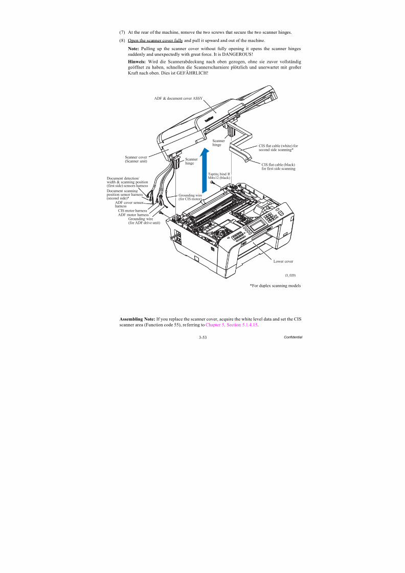
8/15/2019 Brother MFC 6510dw Sm
http://slidepdf.com/reader/full/brother-mfc-6510dw-sm 178/392
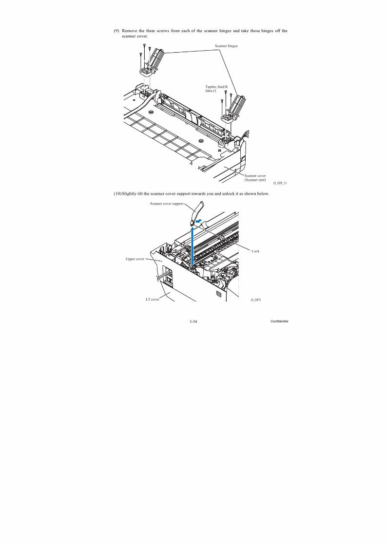
8/15/2019 Brother MFC 6510dw Sm
http://slidepdf.com/reader/full/brother-mfc-6510dw-sm 179/392
3-54 Confidential
(9) Remove the three screws from each of the scanner hinges and take those hinges off thescanner cover.
(10)Slightly tilt the scanner cover support towards you and unlock it as shown below.
(3_020_1)
Taptite, bind BM4x12
Scanner cover(Scanner unit)
Scanner hinges
(3_047)LT cover
Scanner cover support
Upper cover
Lock
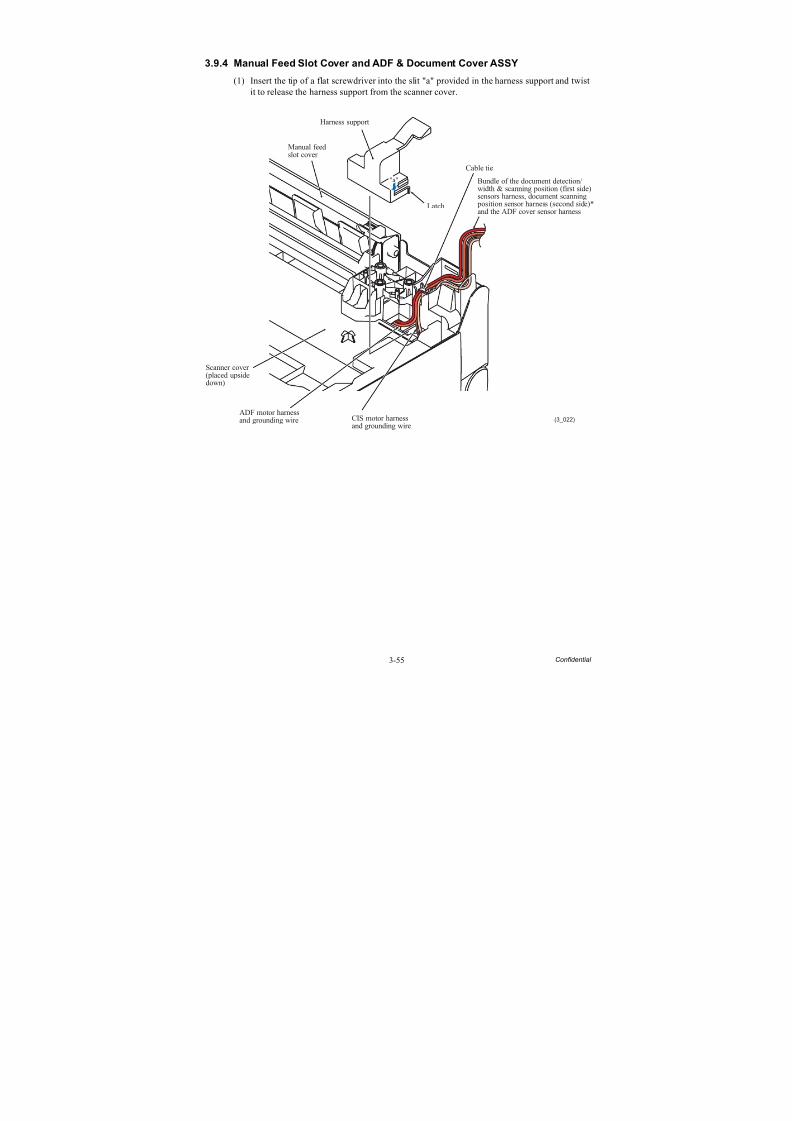
8/15/2019 Brother MFC 6510dw Sm
http://slidepdf.com/reader/full/brother-mfc-6510dw-sm 180/392
3-55 Confidential
3.9.4 Manual Feed Slot Cover and ADF & Document Cover ASSY
(1) Insert the tip of a flat screwdriver into the slit "a" provided in the harness support and twistit to release the harness support from the scanner cover.
(3_022)CIS motor harnessand grounding wire
"a"
Harness support
Scanner cover
(placed upsidedown)
ADF motor harnessand grounding wire
Cable tie
Latch
Manual feedslot cover
Bundle of the document detection/width & scanning position (first side)sensors harness, document scanning position sensor harness (second side)*and the ADF cover sensor harness
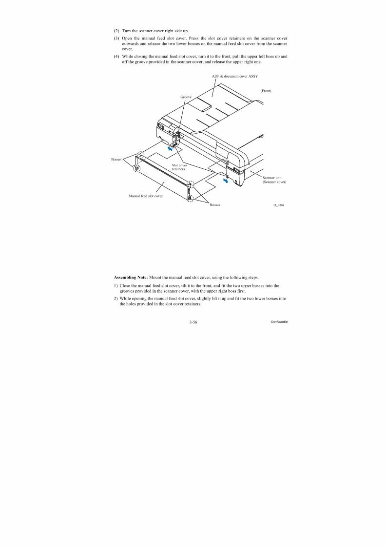
8/15/2019 Brother MFC 6510dw Sm
http://slidepdf.com/reader/full/brother-mfc-6510dw-sm 181/392
3-56 Confidential
(2) Turn the scanner cover right side up.
(3) Open the manual feed slot cover. Press the slot cover retainers on the scanner cover outwards and release the two lower bosses on the manual feed slot cover from the scanner cover.
(4) While closing the manual feed slot cover, turn it to the front, pull the upper left boss up and
off the groove provided in the scanner cover, and release the upper right one.
Assembling Note: Mount the manual feed slot cover, using the following steps.
1) Close the manual feed slot cover, tilt it to the front, and fit the two upper bosses into thegrooves provided in the scanner cover, with the upper right boss first.
2) While opening the manual feed slot cover, slightly lift it up and fit the two lower bosses intothe holes provided in the slot cover retainers.
(3_023)
(Front)
ADF & document cover ASSY
Groove
Bosses
Manual feed slot cover
Bosses
Slot coverretainers
Scanner unit(Scanner cover)
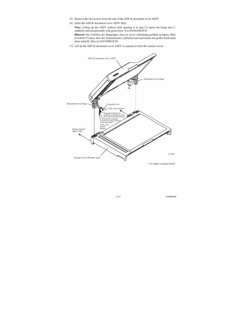
8/15/2019 Brother MFC 6510dw Sm
http://slidepdf.com/reader/full/brother-mfc-6510dw-sm 182/392
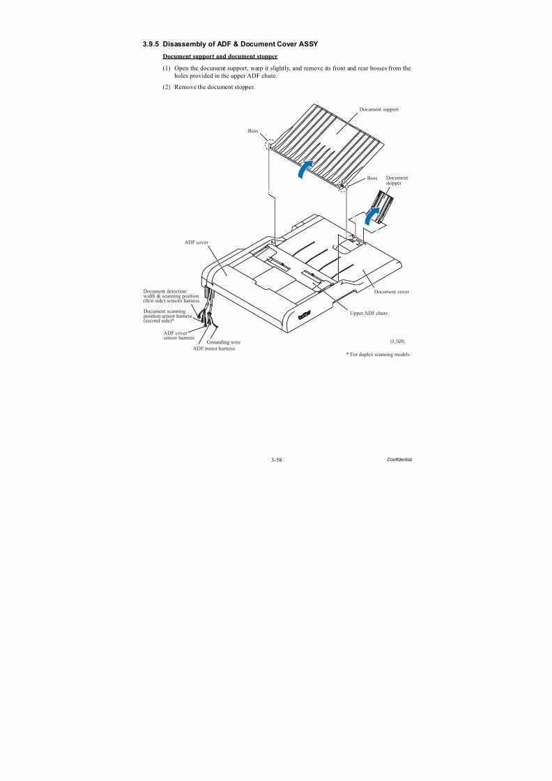
8/15/2019 Brother MFC 6510dw Sm
http://slidepdf.com/reader/full/brother-mfc-6510dw-sm 183/392
3-58 Confidential
3.9.5 Disassembly of ADF & Document Cover ASSY
Document support and document stopper
(1) Open the document support, warp it slightly, and remove its front and rear bosses from theholes provided in the upper ADF chute.
(2) Remove the document stopper.
* For duplex scanning models
Upper ADF chute
(3_025)
Boss
ADF cover
Document cover
Document support
Boss Documentstopper
ADF motor harness
Grounding wire
ADF coversensor harness
Document detection/width & scanning position(first side) sensors harness
Document scanning position sensor harness(second side)*
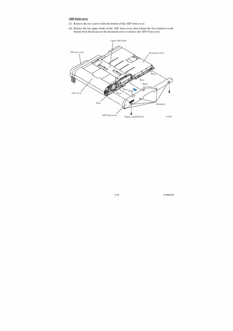
8/15/2019 Brother MFC 6510dw Sm
http://slidepdf.com/reader/full/brother-mfc-6510dw-sm 184/392
3-59 Confidential
ADF front cover
(3) Remove the two screws from the bottom of the ADF front cover.
(4) Release the two upper hooks of the ADF front cover, then release the five retainers on the bottom from the bosses on the document cover to remove the ADF front cover.
Upper ADF chute
(3_026)
ADF cover
Document cover
Boss
Boss
Boss
Boss
Boss
ADF rear cover
ADF front cover Taptite, cup B M3x10
Retainers
Hook
Hook
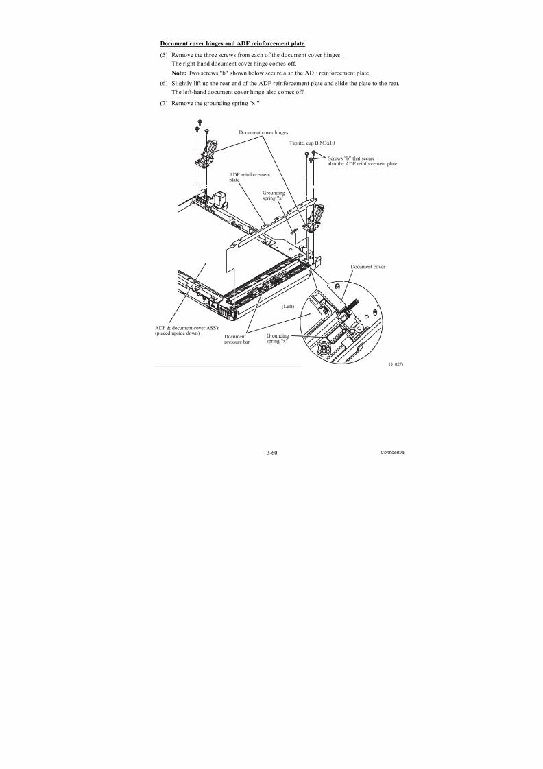
8/15/2019 Brother MFC 6510dw Sm
http://slidepdf.com/reader/full/brother-mfc-6510dw-sm 185/392
3-60 Confidential
Document cover hinges and ADF reinforcement plate
(5) Remove the three screws from each of the document cover hinges.
The right-hand document cover hinge comes off.
Note: Two screws "b" shown below secure also the ADF reinforcement plate.
(6) Slightly lift up the rear end of the ADF reinforcement plate and slide the plate to the rear.The left-hand document cover hinge also comes off.
(7) Remove the grounding spring "x."
(3_027)
Taptite, cup B M3x10
Document cover hinges
ADF reinforcement plate
ADF & document cover ASSY(placed upside down)
Document pressure bar
Groundingspring "x"
Document cover
Screws "b" that securealso the ADF reinforcement plate
Groundingspring "x"
(Left)
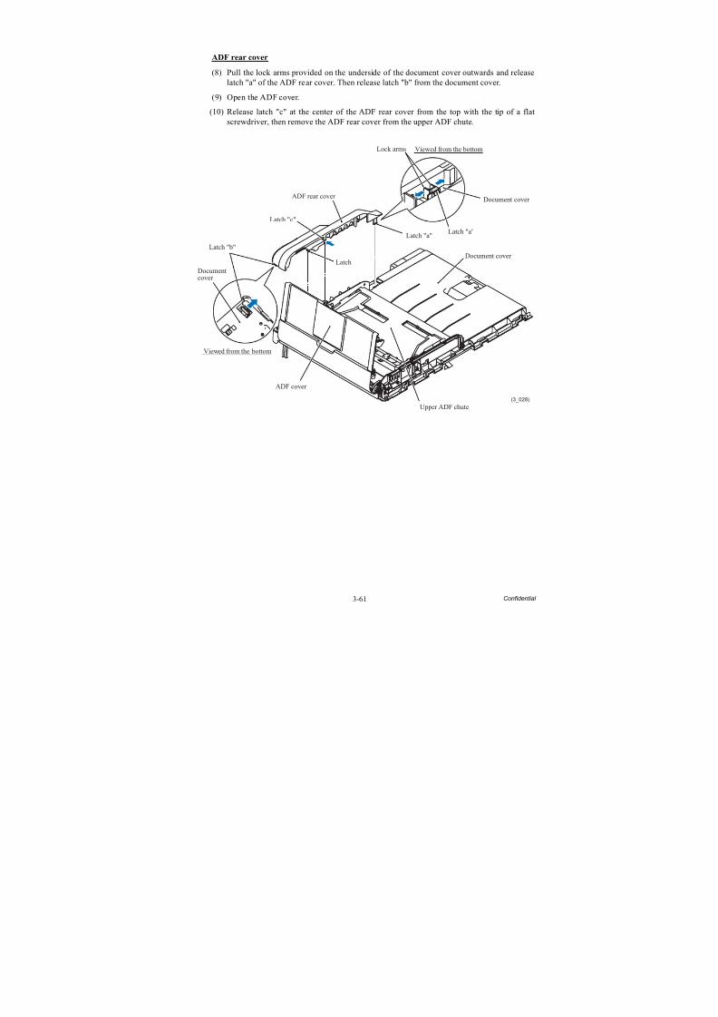
8/15/2019 Brother MFC 6510dw Sm
http://slidepdf.com/reader/full/brother-mfc-6510dw-sm 186/392
3-61 Confidential
ADF rear cover
(8) Pull the lock arms provided on the underside of the document cover outwards and releaselatch "a" of the ADF rear cover. Then release latch "b" from the document cover.
(9) Open the ADF cover.
(10) Release latch "c" at the center of the ADF rear cover from the top with the tip of a flatscrewdriver, then remove the ADF rear cover from the upper ADF chute.
(3_028)
ADF rear cover
Latch "c"
Latch "b"
Documentcover
ADF cover
Upper ADF chute
Document cover
Latch "a"Latch "a"
Document cover
Lock arms
Latch
Viewed from the bottom
Viewed from the bottom
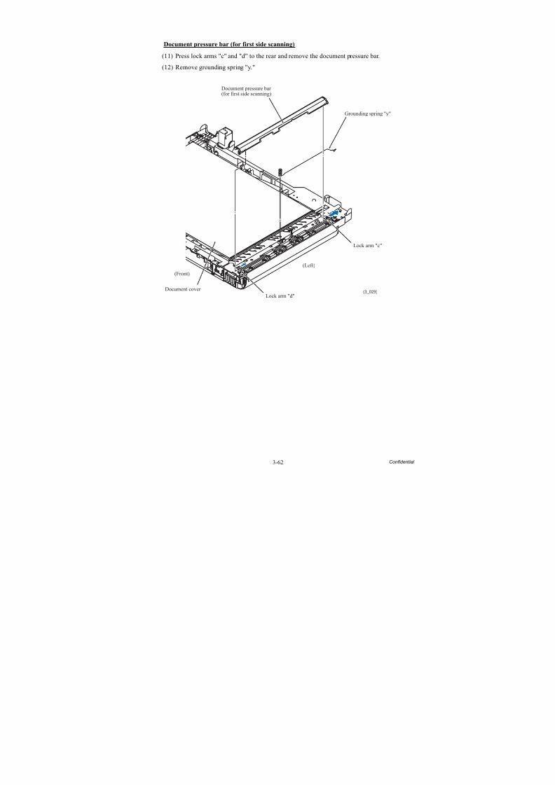
8/15/2019 Brother MFC 6510dw Sm
http://slidepdf.com/reader/full/brother-mfc-6510dw-sm 187/392
3-62 Confidential
Document pressure bar (for first side scanning)
(11) Press lock arms "c" and "d" to the rear and remove the document pressure bar.
(12) Remove grounding spring "y."
(3_029)
Grounding spring "y"
Document pressure bar(for first side scanning)
(Front)
Document cover Lock arm "d"
(Left)
Lock arm "c"
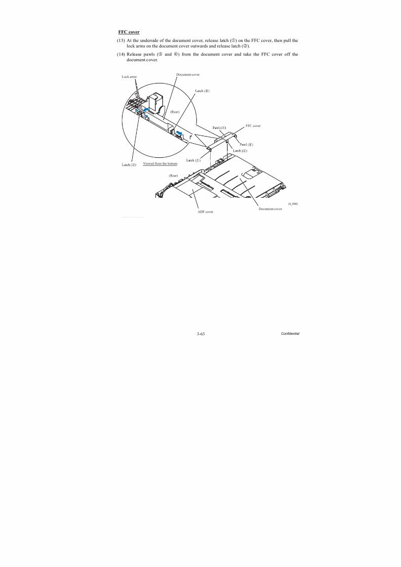
8/15/2019 Brother MFC 6510dw Sm
http://slidepdf.com/reader/full/brother-mfc-6510dw-sm 188/392
3-63 Confidential
FFC cover
(13) At the underside of the document cover, release latch () on the FFC cover, then pull thelock arms on the document cover outwards and release latch ().
(14) Release pawls ( and ) from the document cover and take the FFC cover off thedocument cover.
(3_030)
Lock arms
Viewed from the bottom
(Rear)
ADF cover Document cover
FFC cover
Document cover
(Rear)
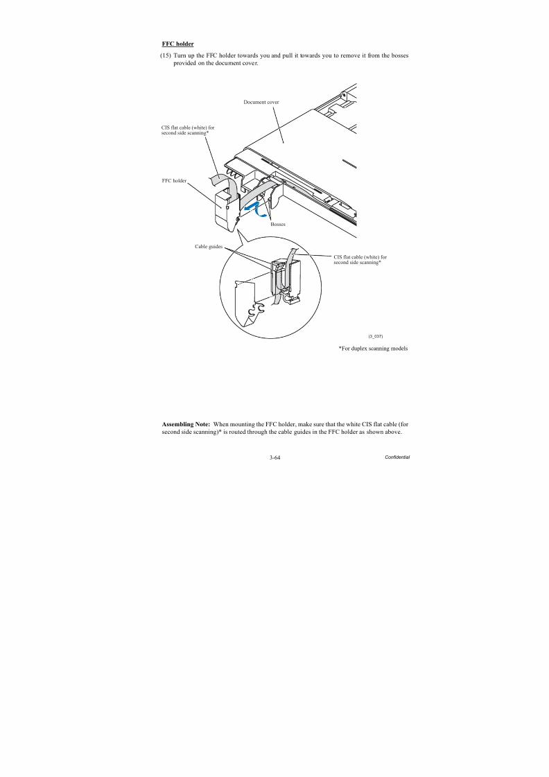
8/15/2019 Brother MFC 6510dw Sm
http://slidepdf.com/reader/full/brother-mfc-6510dw-sm 189/392
3-64 Confidential
FFC holder
(15) Turn up the FFC holder towards you and pull it towards you to remove it from the bosses provided on the document cover.
*For duplex scanning models
Assembling Note: When mounting the FFC holder, make sure that the white CIS flat cable (for second side scanning)* is routed through the cable guides in the FFC holder as shown above.
(3_037)
Bosses
Cable guides
FFC holder
CIS flat cable (white) forsecond side scanning*
Document cover
CIS flat cable (white) for
second side scanning*
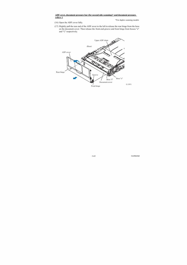
8/15/2019 Brother MFC 6510dw Sm
http://slidepdf.com/reader/full/brother-mfc-6510dw-sm 190/392
3-65 Confidential
ADF cover, document pressure bar (for second side scanning)* and document pressure
rollers 1
*For duplex scanning models(16) Open the ADF cover fully.
(17) Slightly pull the rear end of the ADF cover to the left to release the rear hinge from the boss
on the document cover. Then release the front-end groove and front hinge from bosses "e"and "f," respectively.
(3_031)
ADF cover
Rear hinge
Front hinge
Groove
Document cover
Boss "f"Boss "e"
Upper ADF chute
(Rear)
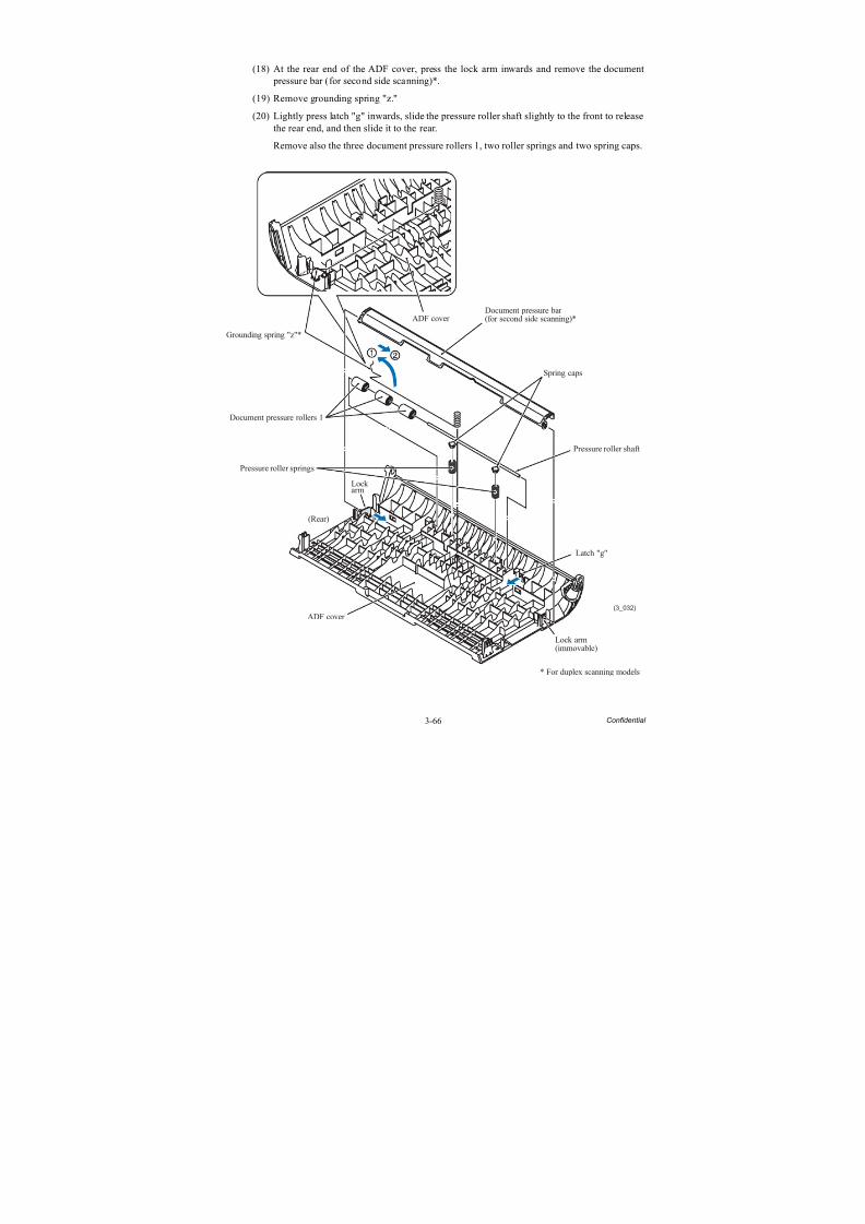
8/15/2019 Brother MFC 6510dw Sm
http://slidepdf.com/reader/full/brother-mfc-6510dw-sm 191/392
3-66 Confidential
(18) At the rear end of the ADF cover, press the lock arm inwards and remove the document pressure bar (for second side scanning)*.
(19) Remove grounding spring "z."
(20) Lightly press latch "g" inwards, slide the pressure roller shaft slightly to the front to releasethe rear end, and then slide it to the rear.
Remove also the three document pressure rollers 1, two roller springs and two spring caps.
(3_032)
Grounding spring "z"*
Document pressure rollers 1
Pressure roller springs
Lockarm
(Rear)
ADF cover
ADF cover
Lock arm(immovable)
Latch "g"
Pressure roller shaft
Spring caps
Document pressure bar(for second side scanning)*
* For duplex scanning models
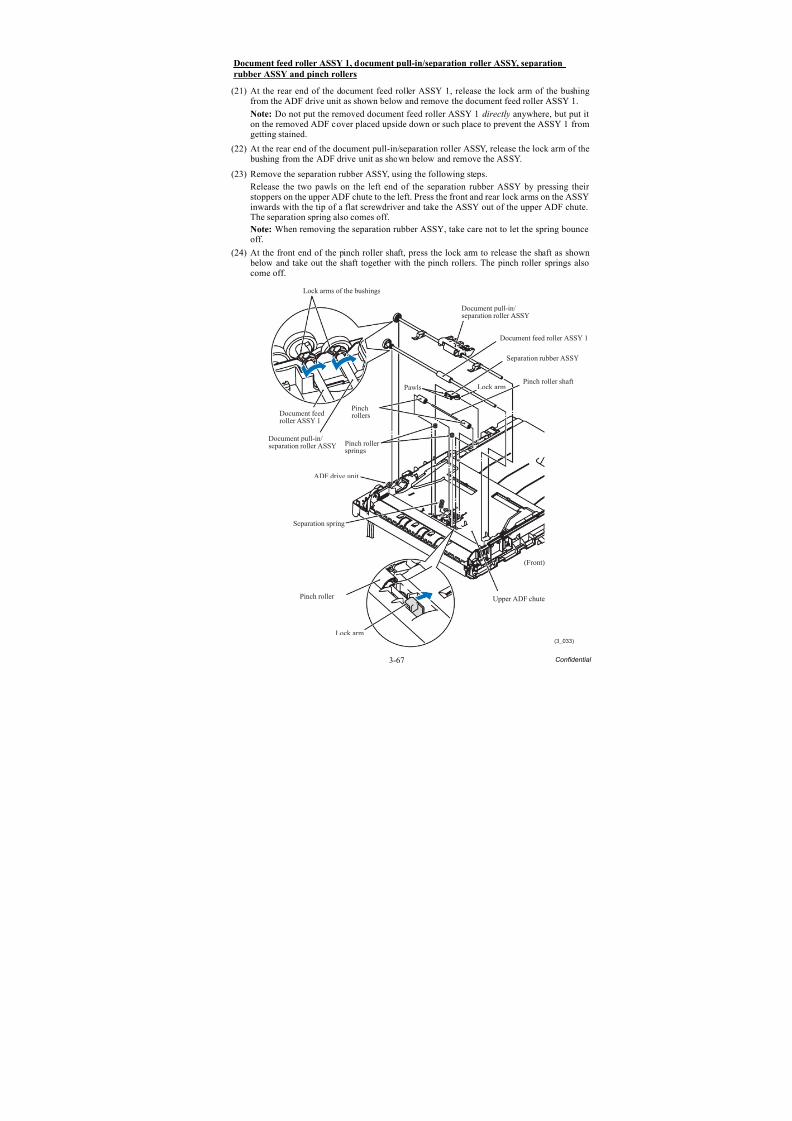
8/15/2019 Brother MFC 6510dw Sm
http://slidepdf.com/reader/full/brother-mfc-6510dw-sm 192/392
3-67 Confidential
Document feed roller ASSY 1, document pull-in/separation roller ASSY, separation
rubber ASSY and pinch rollers
(21) At the rear end of the document feed roller ASSY 1, release the lock arm of the bushingfrom the ADF drive unit as shown below and remove the document feed roller ASSY 1.
Note: Do not put the removed document feed roller ASSY 1 directly anywhere, but put it
on the removed ADF cover placed upside down or such place to prevent the ASSY 1 fromgetting stained.
(22) At the rear end of the document pull-in/separation roller ASSY, release the lock arm of the bushing from the ADF drive unit as shown below and remove the ASSY.
(23) Remove the separation rubber ASSY, using the following steps.
Release the two pawls on the left end of the separation rubber ASSY by pressing their stoppers on the upper ADF chute to the left. Press the front and rear lock arms on the ASSYinwards with the tip of a flat screwdriver and take the ASSY out of the upper ADF chute.The separation spring also comes off.
Note: When removing the separation rubber ASSY, take care not to let the spring bounceoff.
(24) At the front end of the pinch roller shaft, press the lock arm to release the shaft as shown below and take out the shaft together with the pinch rollers. The pinch roller springs alsocome off.
(3_033)
Document pull-in/separation roller ASSY
Lock arms of the bushings
Document feedroller ASSY 1
Document pull-in/separation roller ASSY
Pinchrollers
Pinch rollersprings
ADF drive unit
Separation spring
Pinch roller
Lock arm
Upper ADF chute
(Front)
Pinch roller shaftPawls Lock arm
Separation rubber ASSY
Document feed roller ASSY 1
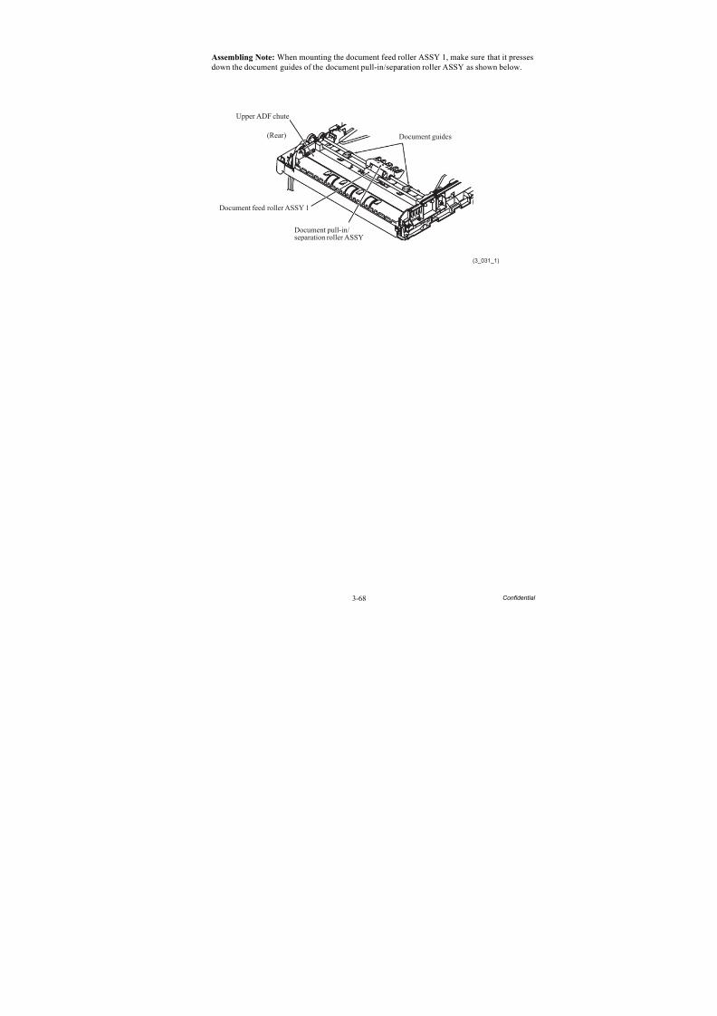
8/15/2019 Brother MFC 6510dw Sm
http://slidepdf.com/reader/full/brother-mfc-6510dw-sm 193/392
3-68 Confidential
Assembling Note: When mounting the document feed roller ASSY 1, make sure that it pressesdown the document guides of the document pull-in/separation roller ASSY as shown below.
(3_031_1)
Upper ADF chute
(Rear)
Document pull-in/separation roller ASSY
Document feed roller ASSY 1
Document guides
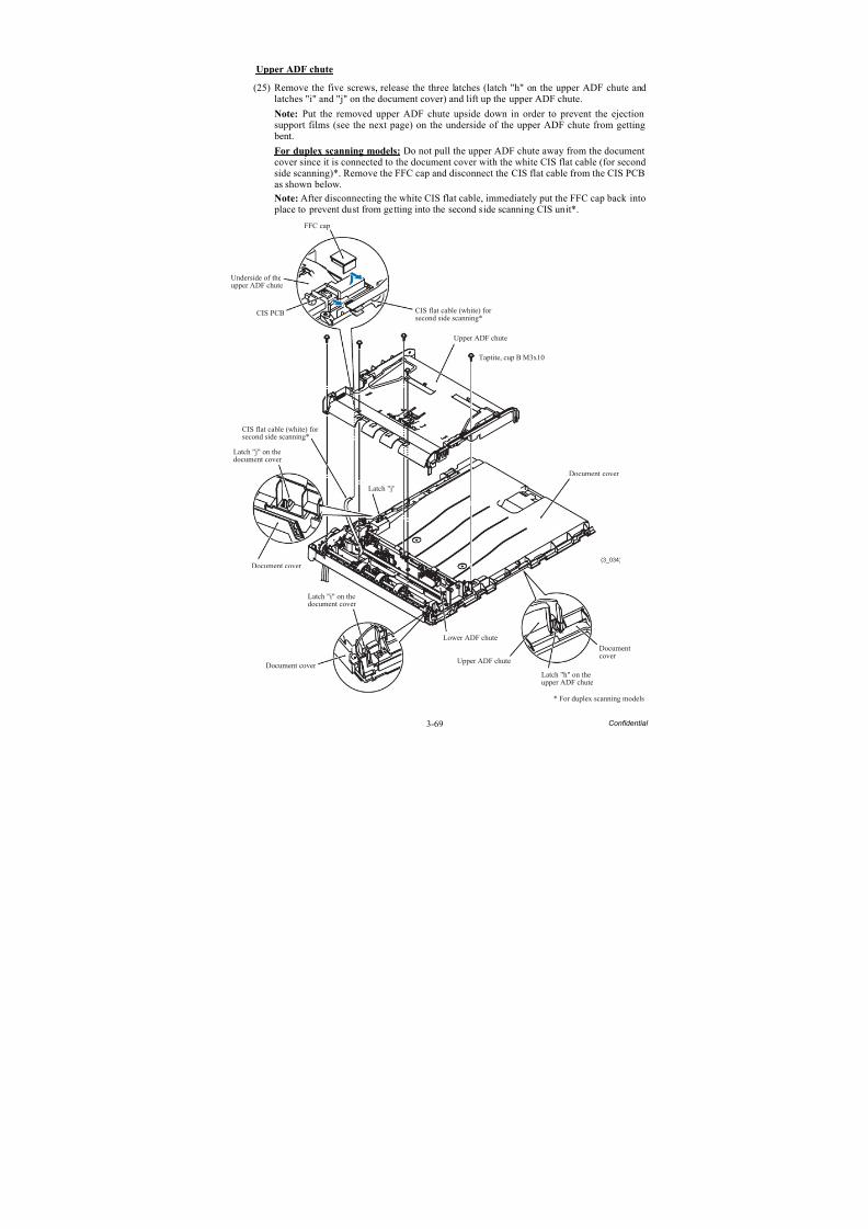
8/15/2019 Brother MFC 6510dw Sm
http://slidepdf.com/reader/full/brother-mfc-6510dw-sm 194/392
3-69 Confidential
Upper ADF chute
(25) Remove the five screws, release the three latches (latch "h" on the upper ADF chute andlatches "i" and "j" on the document cover) and lift up the upper ADF chute.
Note: Put the removed upper ADF chute upside down in order to prevent the ejectionsupport films (see the next page) on the underside of the upper ADF chute from getting
bent.For duplex scanning models: Do not pull the upper ADF chute away from the documentcover since it is connected to the document cover with the white CIS flat cable (for secondside scanning)*. Remove the FFC cap and disconnect the CIS flat cable from the CIS PCBas shown below.
Note: After disconnecting the white CIS flat cable, immediately put the FFC cap back into place to prevent dust from getting into the second side scanning CIS unit*.
(3_034)
* For duplex scanning models
FFC cap
Underside of theupper ADF chute
CIS PCB
Latch "j" on thedocument cover
Document cover
Latch "j"
Latch "i" on thedocument cover
Document cover
Lower ADF chute
Upper ADF chute
Latch "h" on theupper ADF chute
Document cover
Taptite, cup B M3x10
Upper ADF chute
Documentcover
CIS flat cable (white) forsecond side scanning*
CIS flat cable (white) forsecond side scanning*
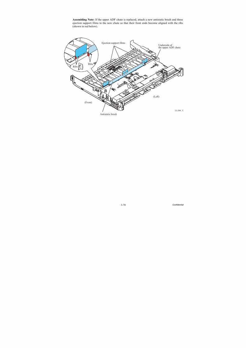
8/15/2019 Brother MFC 6510dw Sm
http://slidepdf.com/reader/full/brother-mfc-6510dw-sm 195/392
3-70 Confidential
Assembling Note: If the upper ADF chute is replaced, attach a new antistatic brush and threeejection support films to the new chute so that their front ends become aligned with the ribs(shown in red below).
Underside ofthe upper ADF chute
(3_034_1)
Ejection support films
Antistatic brush
RibsRibs
(Front)
(Left)
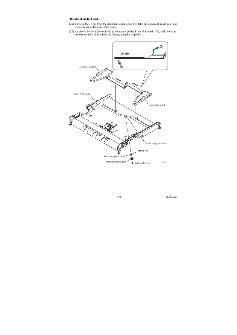
8/15/2019 Brother MFC 6510dw Sm
http://slidepdf.com/reader/full/brother-mfc-6510dw-sm 196/392
3-71 Confidential
Document guides F and R
(26) Remove the screw from the document guide gear, then take the document guide gear andits spring out of the upper ADF chute.
(27) As shown below, slide each of the document guides F and R inwards (), pull down the bottom end (), slide it inwards further, and take it up ().
Document guide F
(3_035)
Document guide R
Upper ADF chute
Spring end
Document guide gear Taptite, B M3x6
Document guide spring
Fit the spring end here.
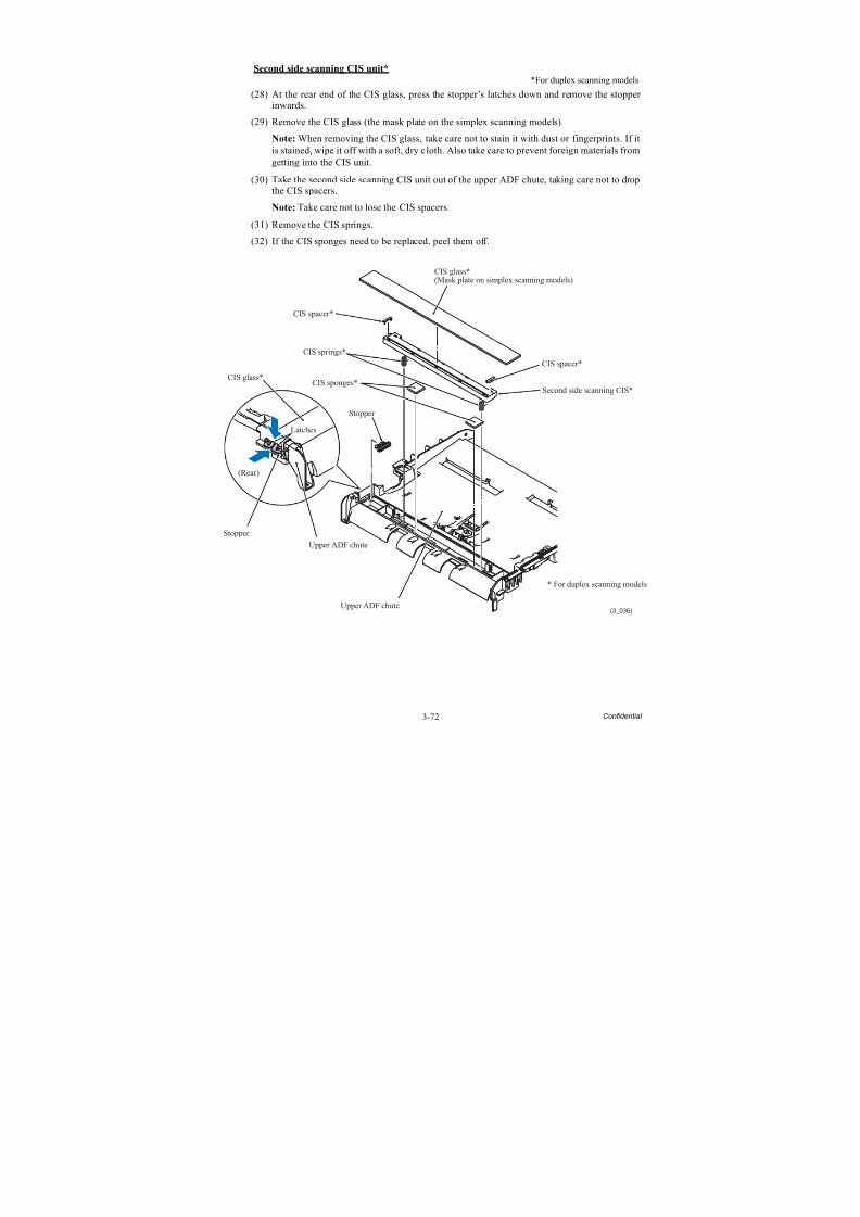
8/15/2019 Brother MFC 6510dw Sm
http://slidepdf.com/reader/full/brother-mfc-6510dw-sm 197/392
3-72 Confidential
Second side scanning CIS unit*
*For duplex scanning models
(28) At the rear end of the CIS glass, press the stopper’s latches down and remove the stopper inwards.
(29) Remove the CIS glass (the mask plate on the simplex scanning models).
Note: When removing the CIS glass, take care not to stain it with dust or fingerprints. If itis stained, wipe it off with a soft, dry cloth. Also take care to prevent foreign materials fromgetting into the CIS unit.
(30) Take the second side scanning CIS unit out of the upper ADF chute, taking care not to dropthe CIS spacers.
Note: Take care not to lose the CIS spacers.
(31) Remove the CIS springs.
(32) If the CIS sponges need to be replaced, peel them off.
(3_036)
* For duplex scanning models
Upper ADF chute
Upper ADF chute
CIS glass*(Mask plate on simplex scanning models)
CIS spacer*
CIS springs*
CIS sponges*CIS glass*
Latches
(Rear)
Stopper
Second side scanning CIS*
CIS spacer*
Stopper
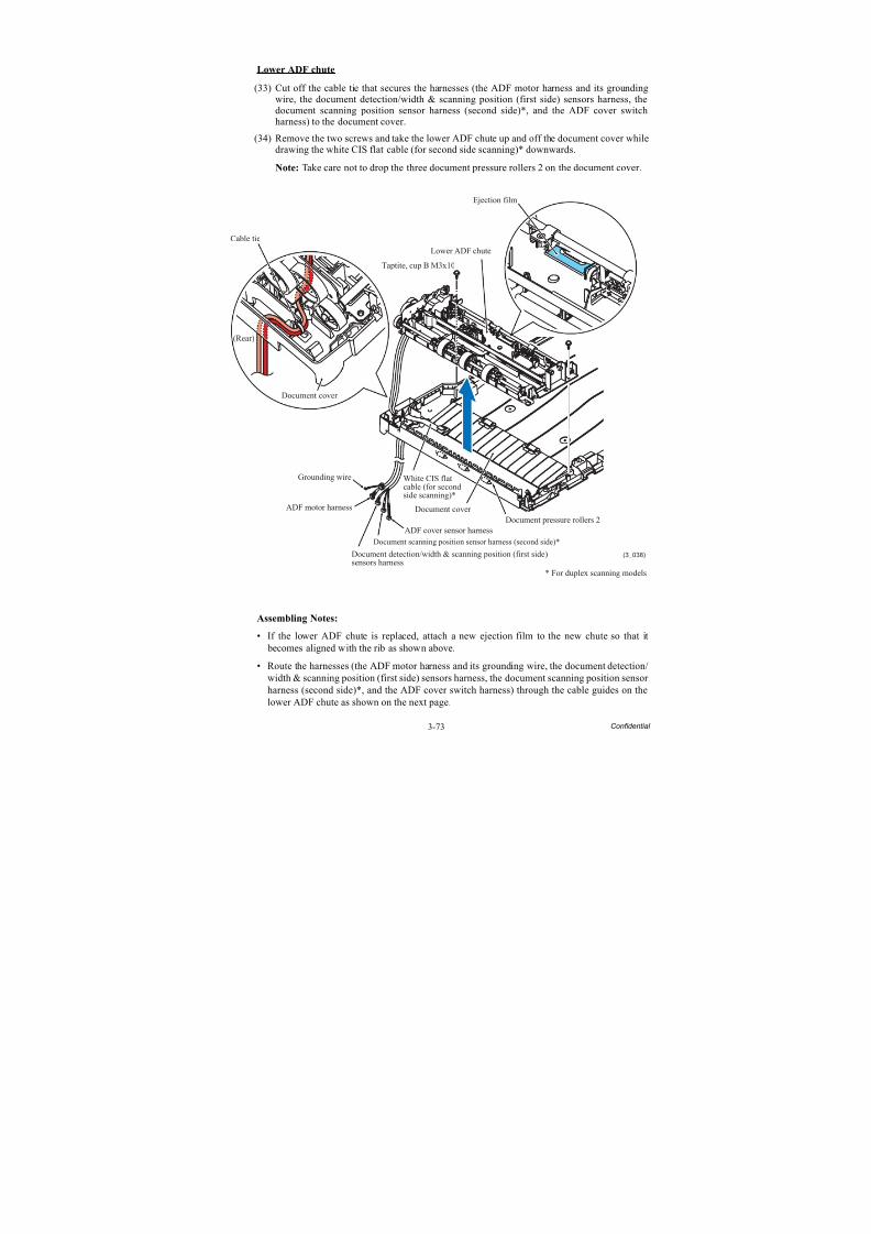
8/15/2019 Brother MFC 6510dw Sm
http://slidepdf.com/reader/full/brother-mfc-6510dw-sm 198/392
3-73 Confidential
Lower ADF chute
(33) Cut off the cable tie that secures the harnesses (the ADF motor harness and its groundingwire, the document detection/width & scanning position (first side) sensors harness, thedocument scanning position sensor harness (second side)*, and the ADF cover switchharness) to the document cover.
(34) Remove the two screws and take the lower ADF chute up and off the document cover whiledrawing the white CIS flat cable (for second side scanning)* downwards.
Note: Take care not to drop the three document pressure rollers 2 on the document cover.
Assembling Notes:
• If the lower ADF chute is replaced, attach a new ejection film to the new chute so that it becomes aligned with the rib as shown above.
• Route the harnesses (the ADF motor harness and its grounding wire, the document detection/width & scanning position (first side) sensors harness, the document scanning position sensor
harness (second side)*, and the ADF cover switch harness) through the cable guides on thelower ADF chute as shown on the next page.
White CIS flatcable (for secondside scanning)*
(3_038)
ADF cover sensor harness
* For duplex scanning models
Cable tie
(Rear)
Grounding wire
ADF motor harness Document cover
Document cover
Lower ADF chute
Taptite, cup B M3x10
Document pressure rollers 2
Document scanning position sensor harness (second side)*
Document detection/width & scanning position (first side)sensors harness
Ejection film
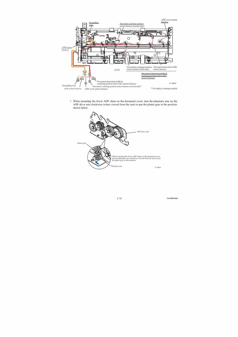
8/15/2019 Brother MFC 6510dw Sm
http://slidepdf.com/reader/full/brother-mfc-6510dw-sm 199/392
3-74 Confidential
• When mounting the lower ADF chute on the document cover, turn the planetary arm on theADF drive unit clockwise (when viewed from the rear) to put the planet gear in the positionshown below.
(3_045a)
ADF motorharness
ADF cover sensorharnessGrounding
wire
* For duplex scanning models
Grounding wire
ADF motor harness ADF cover sensor harness
(Left)
Document detection/width &scanning position (first side) sensors harness
Document scanning position sensor harness (second side)*
Document scanning positionsensor harness (second side)*
Document scanning positionsensor harness (first side)
Document detection/widthsensor harness
Document detection/width &
scanning position (first side)sensors harness
(3_042a)
ADF drive unit
Planetary arm
Planet gear
When mounting the lower ADF chute on the document cover,turn the planetary arm clockwise (viewed from the rear) to putthe planet gear in this position.
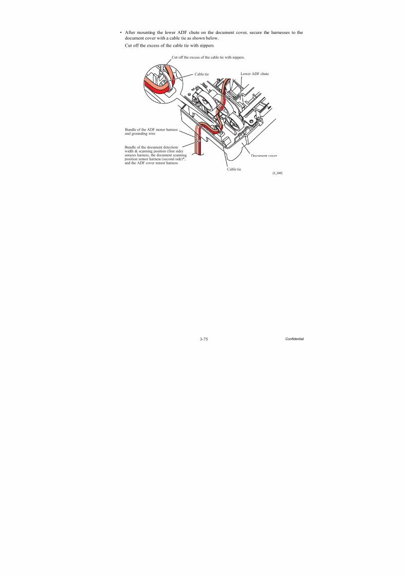
8/15/2019 Brother MFC 6510dw Sm
http://slidepdf.com/reader/full/brother-mfc-6510dw-sm 200/392
3-75 Confidential
• After mounting the lower ADF chute on the document cover, secure the harnesses to thedocument cover with a cable tie as shown below.
Cut off the excess of the cable tie with nippers.
(3_046)
Cut off the excess of the cable tie with nippers.
Cable tie
Bundle of the ADF motor harnessand grounding wire
Bundle of the document detection/width & scanning position (first side)sensors harness, the document scanning position sensor harness (second side)*,and the ADF cover sensor harness
Document cover
Lower ADF chute
Cable tie
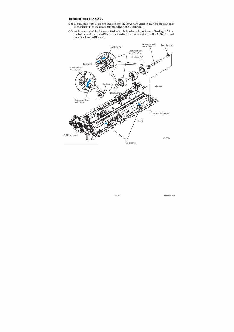
8/15/2019 Brother MFC 6510dw Sm
http://slidepdf.com/reader/full/brother-mfc-6510dw-sm 201/392
3-76 Confidential
Document feed roller ASSY 2
(35) Lightly press each of the two lock arms on the lower ADF chute to the right and slide eachof bushings "a" on the document feed roller ASSY 2 outwards.
(36) At the rear end of the document feed roller shaft, release the lock arm of bushing "b" fromthe hole provided in the ADF drive unit and take the document feed roller ASSY 2 up and
out of the lower ADF chute.
(3_039)
Lock arm of bushing "b"
Bushing "a"
Document feedroller shaft
DF drive unit
Hole
Lock arms
(Left)
Lower ADF chute
(Front)
Lock bushingocumen eeroller shaft
Bushing "a"
Document feedroller ASSY 2
Bushing "a"
Lock arm
Bushing "b"
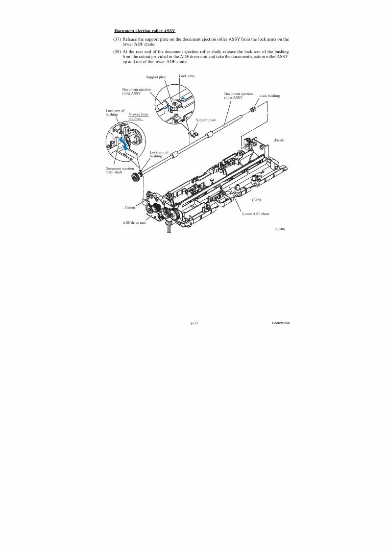
8/15/2019 Brother MFC 6510dw Sm
http://slidepdf.com/reader/full/brother-mfc-6510dw-sm 202/392
3-77 Confidential
Document ejection roller ASSY
(37) Release the support plate on the document ejection roller ASSY from the lock arms on thelower ADF chute.
(38) At the rear end of the document ejection roller shaft, release the lock arm of the bushingfrom the cutout provided in the ADF drive unit and take the document ejection roller ASSY
up and out of the lower ADF chute.
(3_040)
Lock arm of bushing
Document ejectionroller shaft
(Left)
Lower ADF chute
(Front)
Lock bushing
Lock arms
Lock arm of bushing
Viewed fromthe front
Document ejectionroller ASSY Document ejection
roller ASSY
Cutout
ADF drive unit
Support plate
Support plate
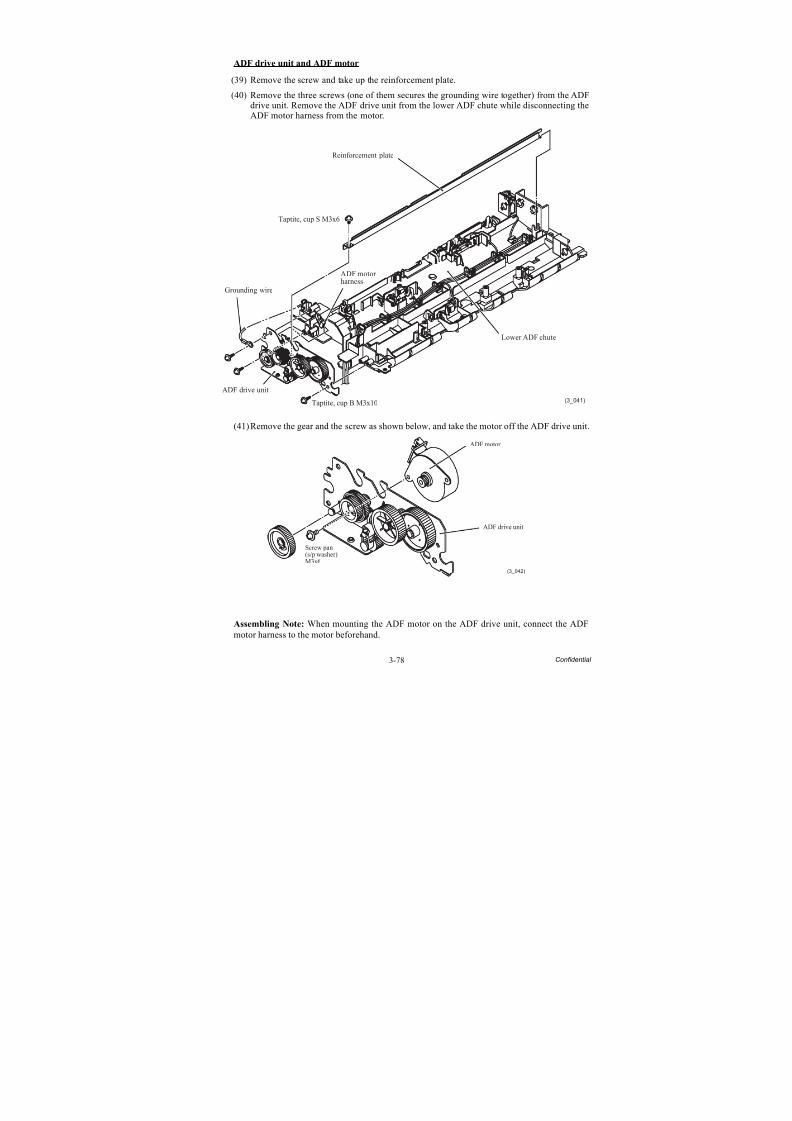
8/15/2019 Brother MFC 6510dw Sm
http://slidepdf.com/reader/full/brother-mfc-6510dw-sm 203/392
3-78 Confidential
ADF drive unit and ADF motor
(39) Remove the screw and take up the reinforcement plate.
(40) Remove the three screws (one of them secures the grounding wire together) from the ADFdrive unit. Remove the ADF drive unit from the lower ADF chute while disconnecting theADF motor harness from the motor.
(41)Remove the gear and the screw as shown below, and take the motor off the ADF drive unit.
Assembling Note: When mounting the ADF motor on the ADF drive unit, connect the ADFmotor harness to the motor beforehand.
(3_041)
Lower ADF chute
ADF drive unit
Taptite, cup B M3x10
Reinforcement plate
Taptite, cup S M3x6
ADF motorharness
Grounding wire
(3_042)
ADF drive unit
ADF motor
Screw pan(s/p washer)M3x6
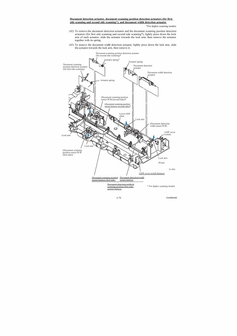
8/15/2019 Brother MFC 6510dw Sm
http://slidepdf.com/reader/full/brother-mfc-6510dw-sm 204/392
3-79 Confidential
Document detection actuator, document scanning position detection actuators (for first
side scanning and second side scanning*), and document width detection actuator
*For duplex scanning models
(42) To remove the document detection actuator and the document scanning position detectionactuators (for first side scanning and second side scanning*), lightly press down the lock
arm of each actuator, slide the actuator towards the lock arm, then remove the actuator together with its spring.
(43) To remove the document width detection actuator, lightly press down the lock arm, slidethe actuator towards the lock arm, then remove it.
(3_043)
* For duplex scanning models
Document scanning position detection actuator(for first side scanning)
Actuator spring
Actuator spring
Lower ADFchute
Lock arm
(Front)
(Document scanning position sensor PCB(first side))
(ADF coverswitch)
(ADF cover switch harness)
Actuator spring*
Lock arm
Lock arm
Lock arm
(Document scanning positionsensor PCB (second side))*
Document scanning position detection actuator(for second side scanning)*
(Document scanning positionsensor harness (second side))*
(Document detection/width sensor PCB)
Document width detection
actuator
Document detectionactuator
Document scanning positionsensor harness (first side)
Document detection/widthsensor harness
Document detection/width &scanning position (first side)sensors harness
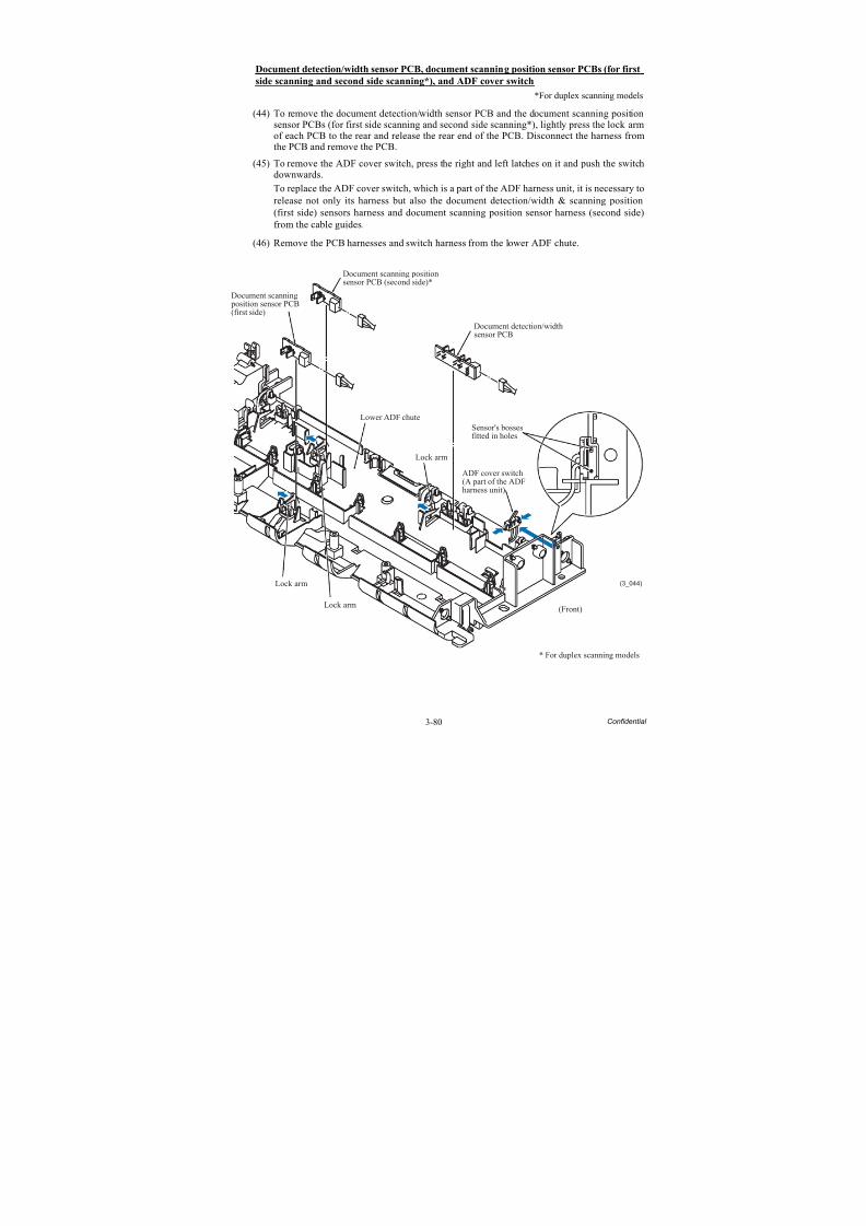
8/15/2019 Brother MFC 6510dw Sm
http://slidepdf.com/reader/full/brother-mfc-6510dw-sm 205/392
3-80 Confidential
Document detection/width sensor PCB, document scanning position sensor PCBs (for first
side scanning and second side scanning*), and ADF cover switch
*For duplex scanning models
(44) To remove the document detection/width sensor PCB and the document scanning positionsensor PCBs (for first side scanning and second side scanning*), lightly press the lock arm
of each PCB to the rear and release the rear end of the PCB. Disconnect the harness fromthe PCB and remove the PCB.
(45) To remove the ADF cover switch, press the right and left latches on it and push the switchdownwards.
To replace the ADF cover switch, which is a part of the ADF harness unit, it is necessary torelease not only its harness but also the document detection/width & scanning position(first side) sensors harness and document scanning position sensor harness (second side)from the cable guides.
(46) Remove the PCB harnesses and switch harness from the lower ADF chute.
* For duplex scanning models
(3_044)Lock arm
Lock arm
Sensor's bossesfitted in holes
ADF cover switch(A part of the ADFharness unit)
(Front)
Lock arm
Lower ADF chute
Document scanning positionsensor PCB (second side)*
Document detection/widthsensor PCB
Document scanning position sensor PCB(first side)
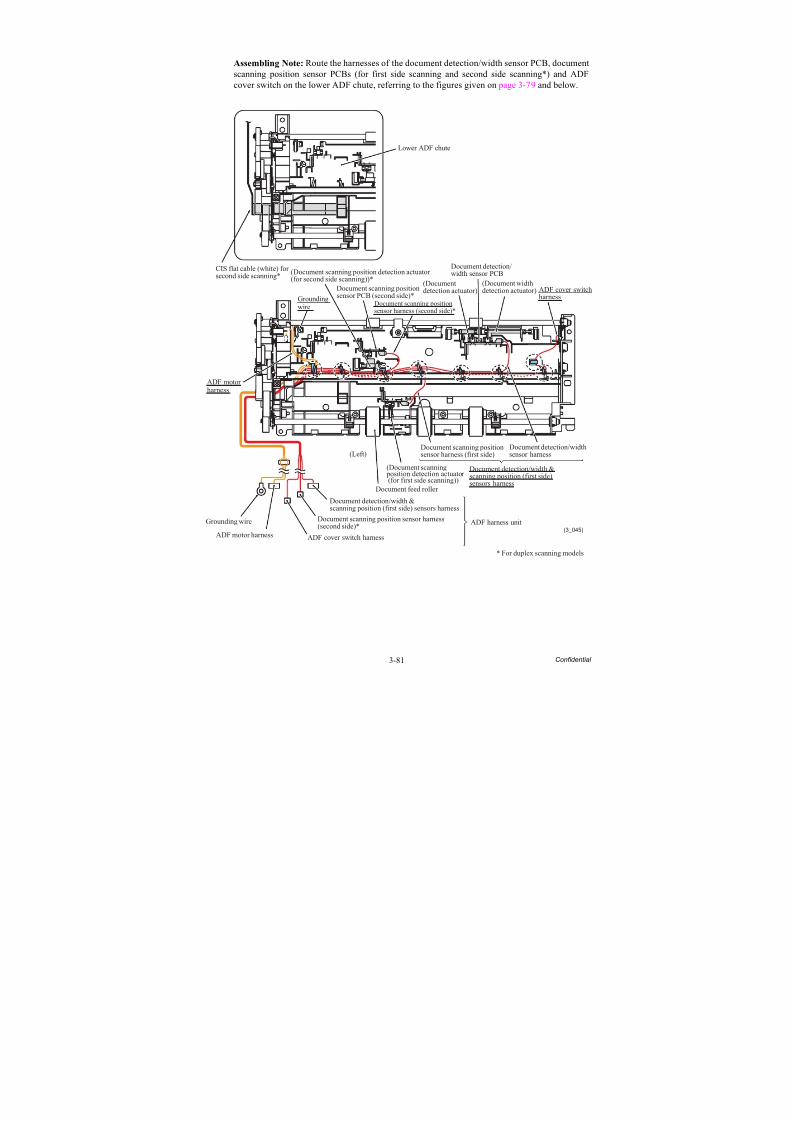
8/15/2019 Brother MFC 6510dw Sm
http://slidepdf.com/reader/full/brother-mfc-6510dw-sm 206/392
3-81 Confidential
Assembling Note: Route the harnesses of the document detection/width sensor PCB, documentscanning position sensor PCBs (for first side scanning and second side scanning*) and ADFcover switch on the lower ADF chute, referring to the figures given on page 3-79 and below.
(3_045)
ADF motorharness
Grounding wire
ADF motor harness ADF cover switch harness
Document feed roller
(Left)
(Document scanning position detection actuator (for first side scanning))
Document scanning positionsensor harness (first side)
Document detection/widthsensor harness
ADF cover switchharness
(Document widthdetection actuator)
Document detection/width sensor PCB
(Documentdetection actuator)
Groundingwire
* For duplex scanning models
Lower ADF chute
CIS flat cable (white) forsecond side scanning*
Document detection/width &scanning position (first side) sensors harness
Document detection/width &scanning position (first side)sensors harness
Document scanning position sensor harness(second side)*
Document scanning positionsensor harness (second side)*
(Document scanning position detection actuator(for second side scanning))*
Document scanning positionsensor PCB (second side)*
ADF harness unit
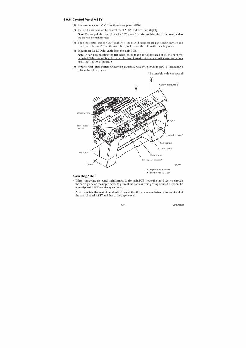
8/15/2019 Brother MFC 6510dw Sm
http://slidepdf.com/reader/full/brother-mfc-6510dw-sm 207/392
3-82 Confidential
3.9.6 Control Panel ASSY
(1) Remove four screws "a" from the control panel ASSY.
(2) Pull up the rear end of the control panel ASSY and turn it up slightly.
Note: Do not pull the control panel ASSY away from the machine since it is connected to
the machine with harnesses.(3) Slide the control panel ASSY slightly to the rear, disconnect the panel-main harness and
touch panel harness* from the main PCB, and release them from their cable guides.
(4) Disconnect the LCD flat cable from the main PCB.
Note: After disconnecting the flat cable, check that it is not damaged at its end or short-circuited. When connecting the flat cable, do not insert it at an angle. After insertion, check again that it is not at an angle.
(5) Models with touch panel: Release the grounding wire by removing screw "b" and removeit from the cable guides.
*For models with touch panel
"a": Taptite, cup B M3x10"b": Taptite, cup S M3x6*
Assembling Notes:
• When connecting the panel-main harness to the main PCB, route the taped section throughthe cable guide on the upper cover to prevent the harness from getting crushed between thecontrol panel ASSY and the upper cover.
• After mounting the control panel ASSY, check that there is no gap between the front end of
the control panel ASSY and that of the upper cover.
(3_048)
Panel-mainharness
Upper cover
Cable guide
LT cover
Touch panel harness*
Cable guides
Cable guides
LCD flat cable
Grounding wire*
Control panel ASSY
"a"
"a"
"a"
"a"
"b" *
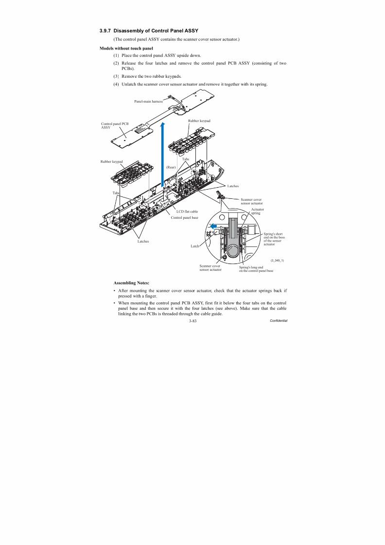
8/15/2019 Brother MFC 6510dw Sm
http://slidepdf.com/reader/full/brother-mfc-6510dw-sm 208/392
3-83 Confidential
3.9.7 Disassembly of Control Panel ASSY
(The control panel ASSY contains the scanner cover sensor actuator.)
Models without touch panel
(1) Place the control panel ASSY upside down.
(2) Release the four latches and remove the control panel PCB ASSY (consisting of twoPCBs).
(3) Remove the two rubber keypads.
(4) Unlatch the scanner cover sensor actuator and remove it together with its spring.
Assembling Notes:
• After mounting the scanner cover sensor actuator, check that the actuator springs back if pressed with a finger.
• When mounting the control panel PCB ASSY, first fit it below the four tabs on the control panel base and then secure it with the four latches (see above). Make sure that the cablelinking the two PCBs is threaded through the cable guide.
(3_049_1)
Panel-main harness
Control panel PCBASSY
Rubber keypadTabs
Latches
Latches
Tabs
Control panel base
LCD flat cable
(Rear)
Rubber keypad
Scanner coversensor actuator
Actuatorspring
Scanner coversensor actuator
Latch
Spring's long endon the control panel base
Spring's shortend on the bossof the sensor
actuator
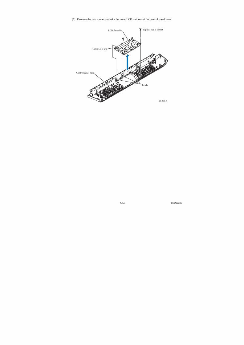
8/15/2019 Brother MFC 6510dw Sm
http://slidepdf.com/reader/full/brother-mfc-6510dw-sm 209/392
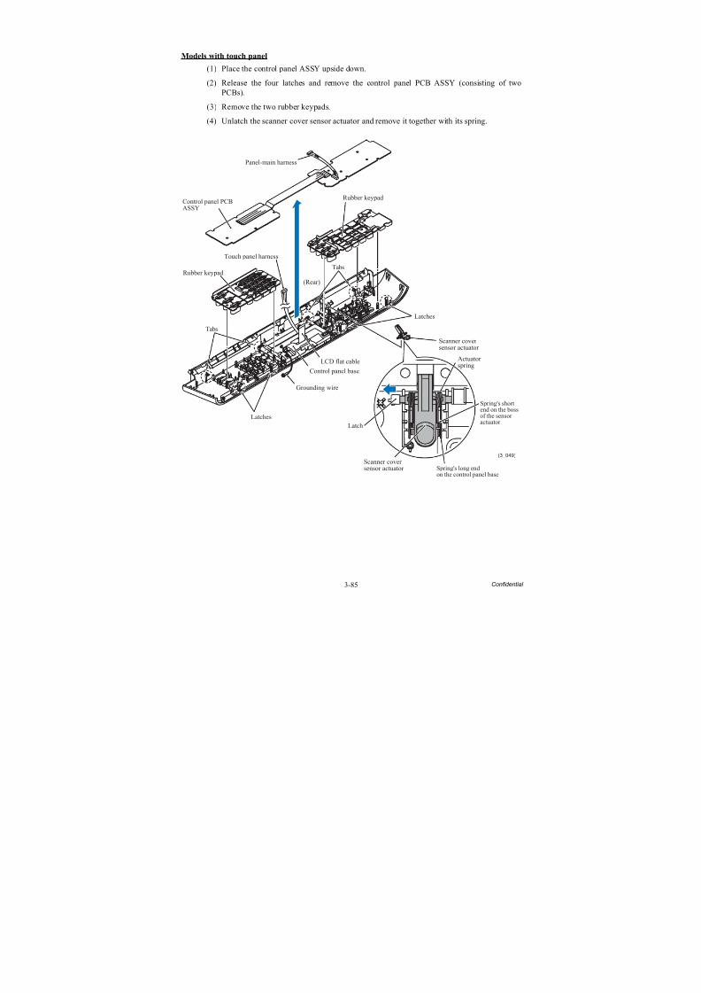
8/15/2019 Brother MFC 6510dw Sm
http://slidepdf.com/reader/full/brother-mfc-6510dw-sm 210/392
3-85 Confidential
Models with touch panel
(1) Place the control panel ASSY upside down.
(2) Release the four latches and remove the control panel PCB ASSY (consisting of twoPCBs).
(3) Remove the two rubber keypads.
(4) Unlatch the scanner cover sensor actuator and remove it together with its spring.
(3_049)
Panel-main harness
Control panel PCBASSY
Rubber keypad
Touch panel harness
Tabs
Latches
Latches
Tabs
Grounding wire
Control panel base
LCD flat cable Actuatorspring
Scanner coversensor actuator
(Rear)
Rubber keypad
Scanner coversensor actuator
Latch
Spring's long endon the control panel base
Spring's shortend on the bossof the sensoractuator
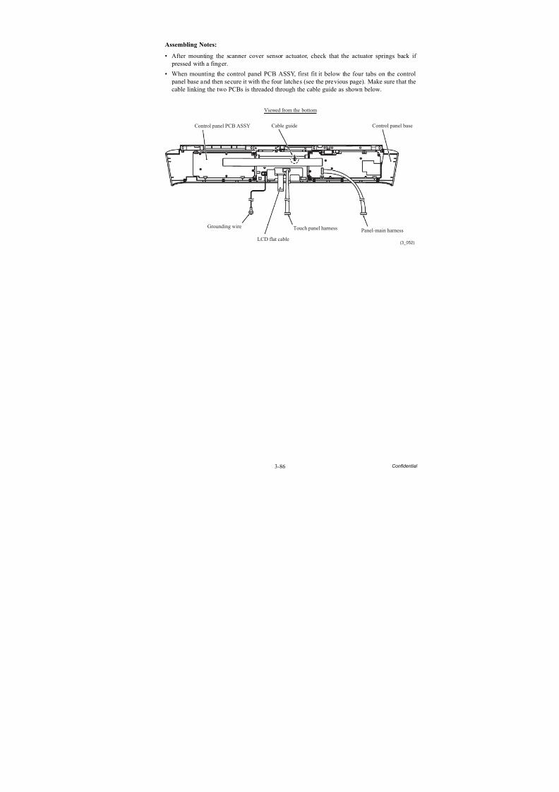
8/15/2019 Brother MFC 6510dw Sm
http://slidepdf.com/reader/full/brother-mfc-6510dw-sm 211/392
3-86 Confidential
Assembling Notes:
• After mounting the scanner cover sensor actuator, check that the actuator springs back if pressed with a finger.
• When mounting the control panel PCB ASSY, first fit it below the four tabs on the control panel base and then secure it with the four latches (see the previous page). Make sure that the
cable linking the two PCBs is threaded through the cable guide as shown below.
(3_052)
Cable guide
Viewed from the bottom
Control panel PCB ASSY
Grounding wire
LCD flat cable
Touch panel harness Panel-main harness
Control panel base
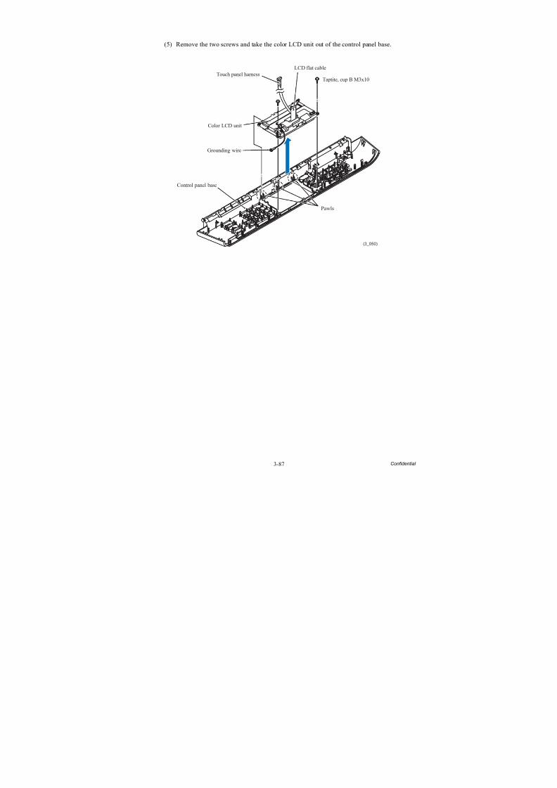
8/15/2019 Brother MFC 6510dw Sm
http://slidepdf.com/reader/full/brother-mfc-6510dw-sm 212/392
3-87 Confidential
(5) Remove the two screws and take the color LCD unit out of the control panel base.
(3_050)
LCD flat cable
Touch panel harness
Color LCD unit
Grounding wire
Control panel base
Pawls
Taptite, cup B M3x10
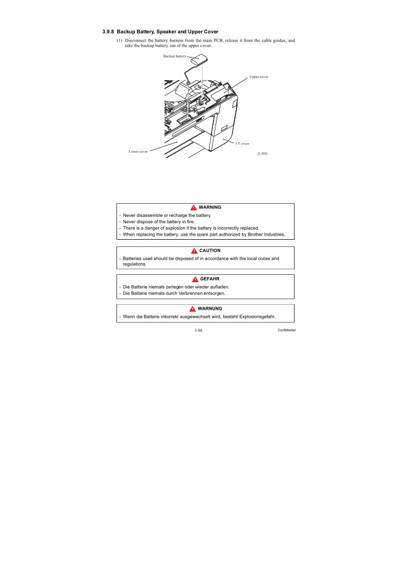
8/15/2019 Brother MFC 6510dw Sm
http://slidepdf.com/reader/full/brother-mfc-6510dw-sm 213/392
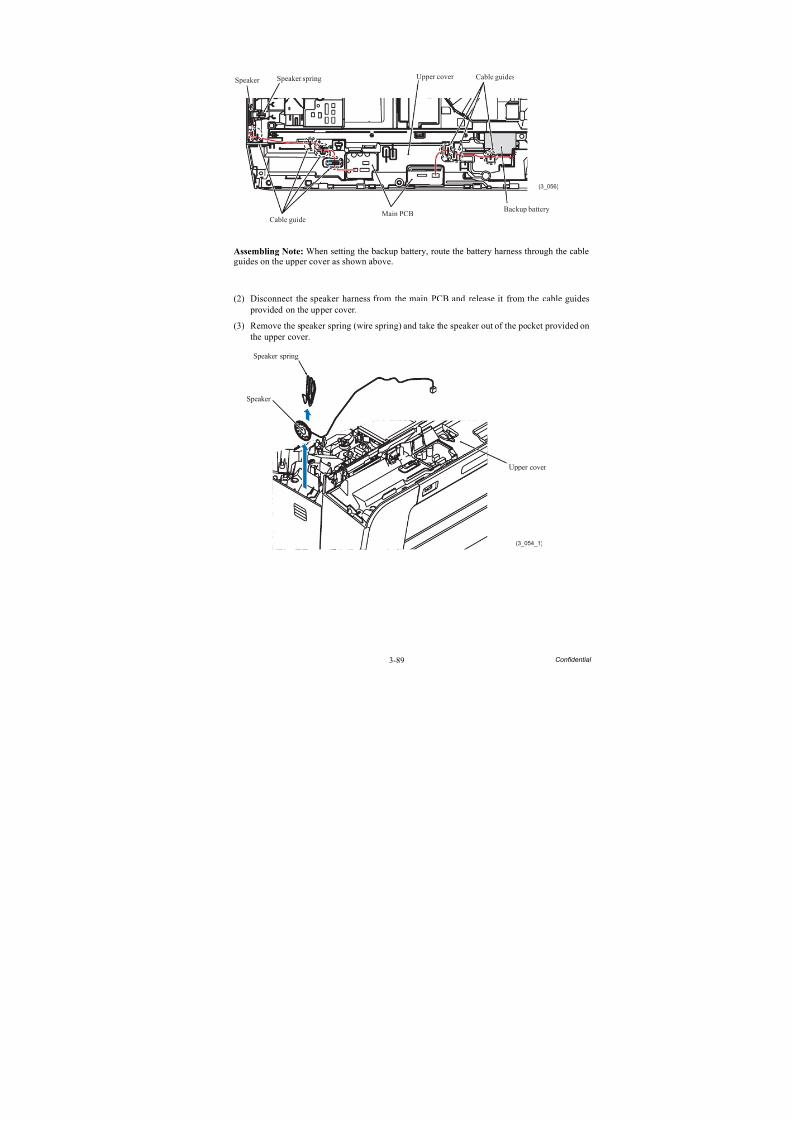
8/15/2019 Brother MFC 6510dw Sm
http://slidepdf.com/reader/full/brother-mfc-6510dw-sm 214/392
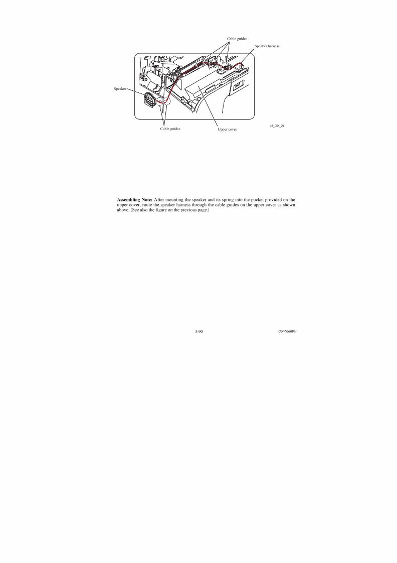
8/15/2019 Brother MFC 6510dw Sm
http://slidepdf.com/reader/full/brother-mfc-6510dw-sm 215/392
3-90 Confidential
Assembling Note: After mounting the speaker and its spring into the pocket provided on theupper cover, route the speaker harness through the cable guides on the upper cover as shownabove. (See also the figure on the previous page.)
(3_054_2)
Speaker
Upper cover
Cable guides
Cable guides
Speaker harness
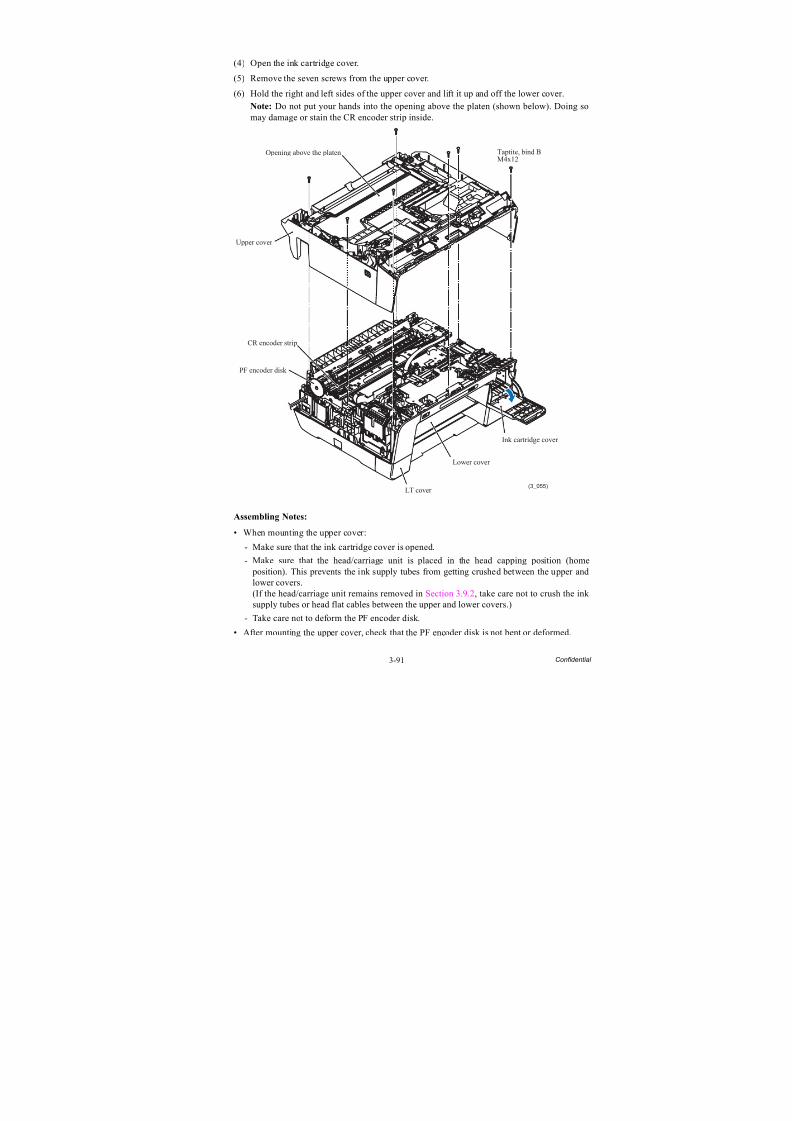
8/15/2019 Brother MFC 6510dw Sm
http://slidepdf.com/reader/full/brother-mfc-6510dw-sm 216/392
3-91 Confidential
(4) Open the ink cartridge cover.
(5) Remove the seven screws from the upper cover.
(6) Hold the right and left sides of the upper cover and lift it up and off the lower cover.
Note: Do not put your hands into the opening above the platen (shown below). Doing somay damage or stain the CR encoder strip inside.
Assembling Notes:
• When mounting the upper cover:
- Make sure that the ink cartridge cover is opened.
- Make sure that the head/carriage unit is placed in the head capping position (home position). This prevents the ink supply tubes from getting crushed between the upper andlower covers.(If the head/carriage unit remains removed in Section 3.9.2, take care not to crush the ink supply tubes or head flat cables between the upper and lower covers.)
- Take care not to deform the PF encoder disk.
• After mounting the upper cover, check that the PF encoder disk is not bent or deformed.
(3_055)
Taptite, bind BM4x12
Opening above the platen
Upper cover
LT cover
PF encoder disk
Ink cartridge cover
CR encoder strip
Lower cover
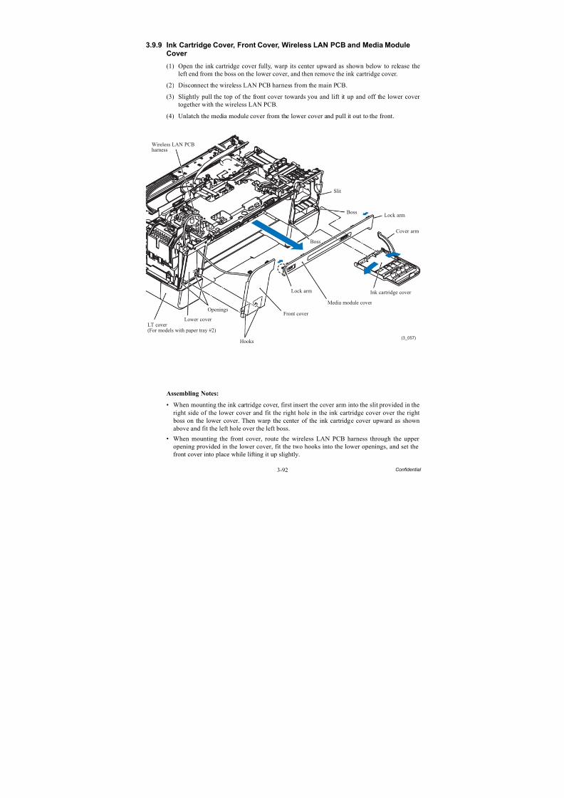
8/15/2019 Brother MFC 6510dw Sm
http://slidepdf.com/reader/full/brother-mfc-6510dw-sm 217/392
3-92 Confidential
3.9.9 Ink Cartridge Cover, Front Cover, Wireless LAN PCB and Media ModuleCover
(1) Open the ink cartridge cover fully, warp its center upward as shown below to release theleft end from the boss on the lower cover, and then remove the ink cartridge cover.
(2) Disconnect the wireless LAN PCB harness from the main PCB.
(3) Slightly pull the top of the front cover towards you and lift it up and off the lower cover together with the wireless LAN PCB.
(4) Unlatch the media module cover from the lower cover and pull it out to the front.
Assembling Notes:
• When mounting the ink cartridge cover, first insert the cover arm into the slit provided in theright side of the lower cover and fit the right hole in the ink cartridge cover over the right boss on the lower cover. Then warp the center of the ink cartridge cover upward as shownabove and fit the left hole over the left boss.
• When mounting the front cover, route the wireless LAN PCB harness through the upper
opening provided in the lower cover, fit the two hooks into the lower openings, and set thefront cover into place while lifting it up slightly.
(3_057)
Slit
Boss
Boss
LT cover(For models with paper tray #2)
Lower cover
Hooks
Front cover
Lock arm
Lock arm
Media module cover
Ink cartridge cover
Cover arm
Openings
Wireless LAN PCBharness
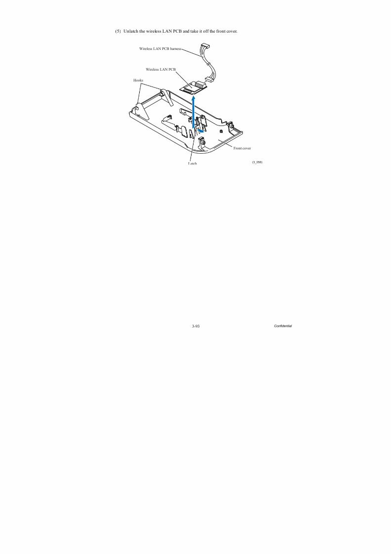
8/15/2019 Brother MFC 6510dw Sm
http://slidepdf.com/reader/full/brother-mfc-6510dw-sm 218/392
3-93 Confidential
(5) Unlatch the wireless LAN PCB and take it off the front cover.
(3_058)
Wireless LAN PCB harness
Wireless LAN PCB
Hooks
Latch
Front cover
8/15/2019 Brother MFC 6510dw Sm
http://slidepdf.com/reader/full/brother-mfc-6510dw-sm 219/392
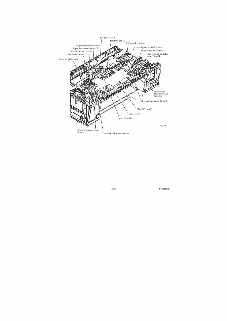
8/15/2019 Brother MFC 6510dw Sm
http://slidepdf.com/reader/full/brother-mfc-6510dw-sm 220/392
3-95 Confidential
(3_059)
ASF motor harness
Ink cartridgedetection sensorflat cable
High-yield ink cartridgesensor flat cable
Ink remaining sensor flat cable
Ink cartridge cover switch harness
ASF encoder harness
Purge cam switch harness
Power supply harness
Switchback paper sensorharness
PF encoder/PF sensor harness
Head flat cable 1
Lower cover
Main PCB shield
Head flat cable 2
Head flat cable 3
Registration sensor harness
Carriage motor harnessPaper feed motor harness
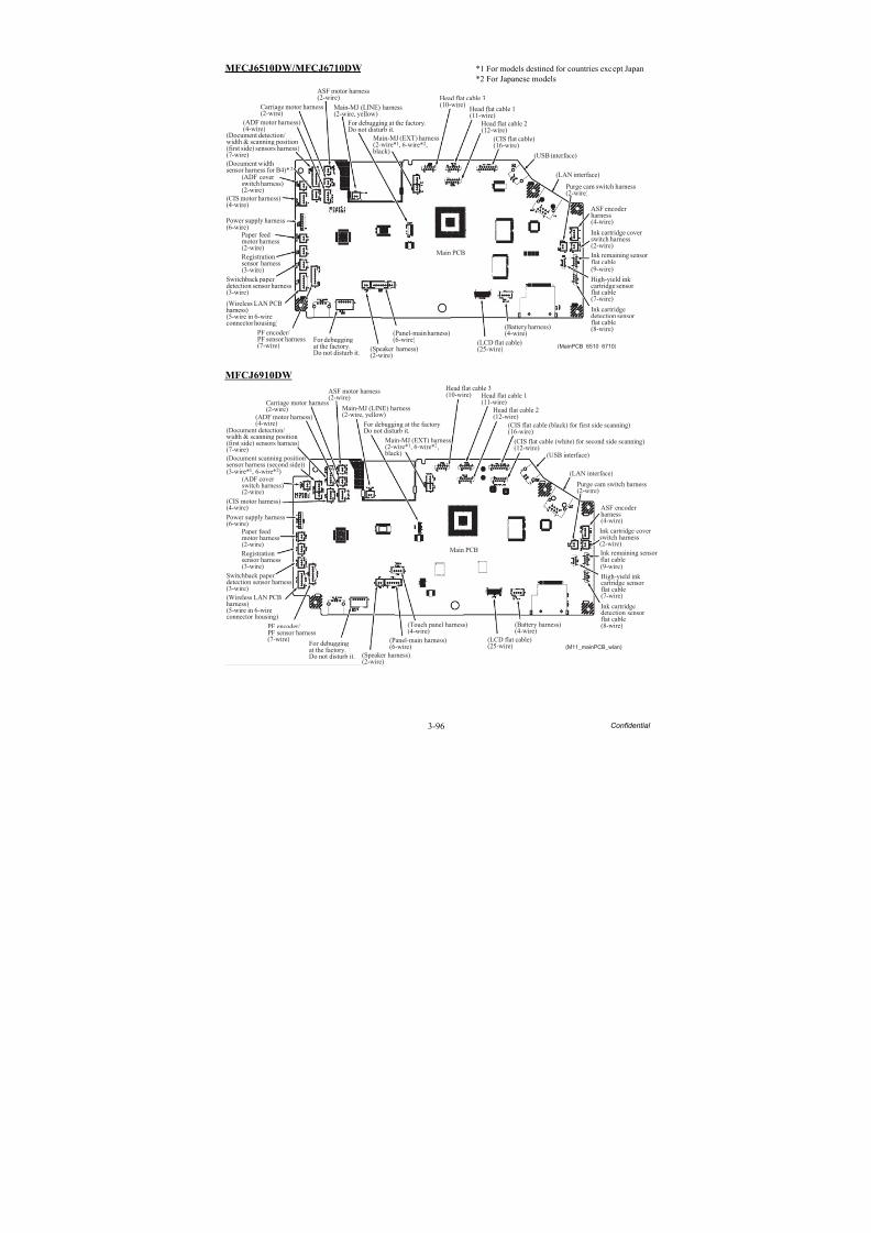
8/15/2019 Brother MFC 6510dw Sm
http://slidepdf.com/reader/full/brother-mfc-6510dw-sm 221/392
3-96 Confidential
MFCJ6510DW/MFCJ6710DW *1 For models destined for countries except Japan
*2 For Japanese models
MFCJ6910DW
(MainPCB_6510_6710)
Main PCB
Main-MJ (LINE) harness(2-wire, yellow)
ASF motor harness(2-wire)
Carriage motor harness(2-wire)
For debugging at the factory.Do not disturb it.
(ADF motor harness)(4-wire)
(Document detection/width & scanning position(first side) sensors harness)(7-wire)
Power supply harness(6-wire)
Paper feedmotor harness(2-wire)
Registrationsensor harness(3-wire)
Switchback paperdetection sensor harness(3-wire)
(Wireless LAN PCBharness)(5-wire in 6-wireconnector housing)
PF encoder/PF sensor harness(7-wire)
For debuggingat the factory.Do not disturb it.
(LCD flat cable)(25-wire)
(Battery harness)(4-wire)
Ink cartridgedetection sensorflat cable(8-wire)
High-yield inkcartridge sensorflat cable(7-wire)
Ink remaining sensorflat cable(9-wire)
Ink cartridge cover switch harness(2-wire)
ASF encoderharness(4-wire)
Purge cam switch harness(2-wire)
(LAN interface)
(USB interface)
Head flat cable 2(12-wire)
Head flat cable 1(11-wire)
Head flat cable 3(10-wire)
Main-MJ (EXT) harness(2-wire*1, 6-wire*2,
black)
(Panel-main harness)(6-wire)
(CIS flat cable)(16-wire)
(CIS motor harness)(4-wire)
(Document widthsensor harness for B4)*2
(ADF coverswitch harness)(2-wire)
(Speaker harness)(2-wire)
(M11_mainPCB_wlan)
Main PCB
Main-MJ (LINE) harness
(2-wire, yellow)
ASF motor harness(2-wire)
Carriage motor harness(2-wire)
For debugging at the factory.Do not disturb it.
(ADF motor harness)(4-wire)
(Document scanning positionsensor harness (second side))(3-wire*1, 6-wire*2)
(ADF coverswitch harness)(2-wire)
(CIS motor harness)(4-wire)
Power supply harness(6-wire)
Paper feedmotor harness(2-wire)
Registrationsensor harness(3-wire)
Switchback paperdetection sensor harness(3-wire)
PF encoder/PF sensor harness(7-wire)
For debuggingat the factory.Do not disturb it. (Speaker harness)
(2-wire)
(Panel-main harness)(6-wire)
(Touch panel harness)(4-wire)
(LCD flat cable)(25-wire)
(Battery harness)(4-wire)
Ink cartridgedetection sensorflat cable(8-wire)
High-yield inkcartridge sensorflat cable(7-wire)
Ink remaining sensorflat cable(9-wire)
Ink cartridge cover switch harness(2-wire)
ASF encoderharness(4-wire)
Purge cam switch harness(2-wire)
(LAN interface)
(USB interface)
(CIS flat cable (white) for second side scanning)(12-wire)
(CIS flat cable (black) for first side scanning)(16-wire)
Head flat cable 2(12-wire)
Head flat cable 1(11-wire)
Head flat cable 3(10-wire)
Main-MJ (EXT) harness(2-wire*1, 6-wire*2,
black)
(Wireless LAN PCBharness)(5-wire in 6-wireconnector housing)
(Document detection/width & scanning position(first side) sensors harness)(7-wire)
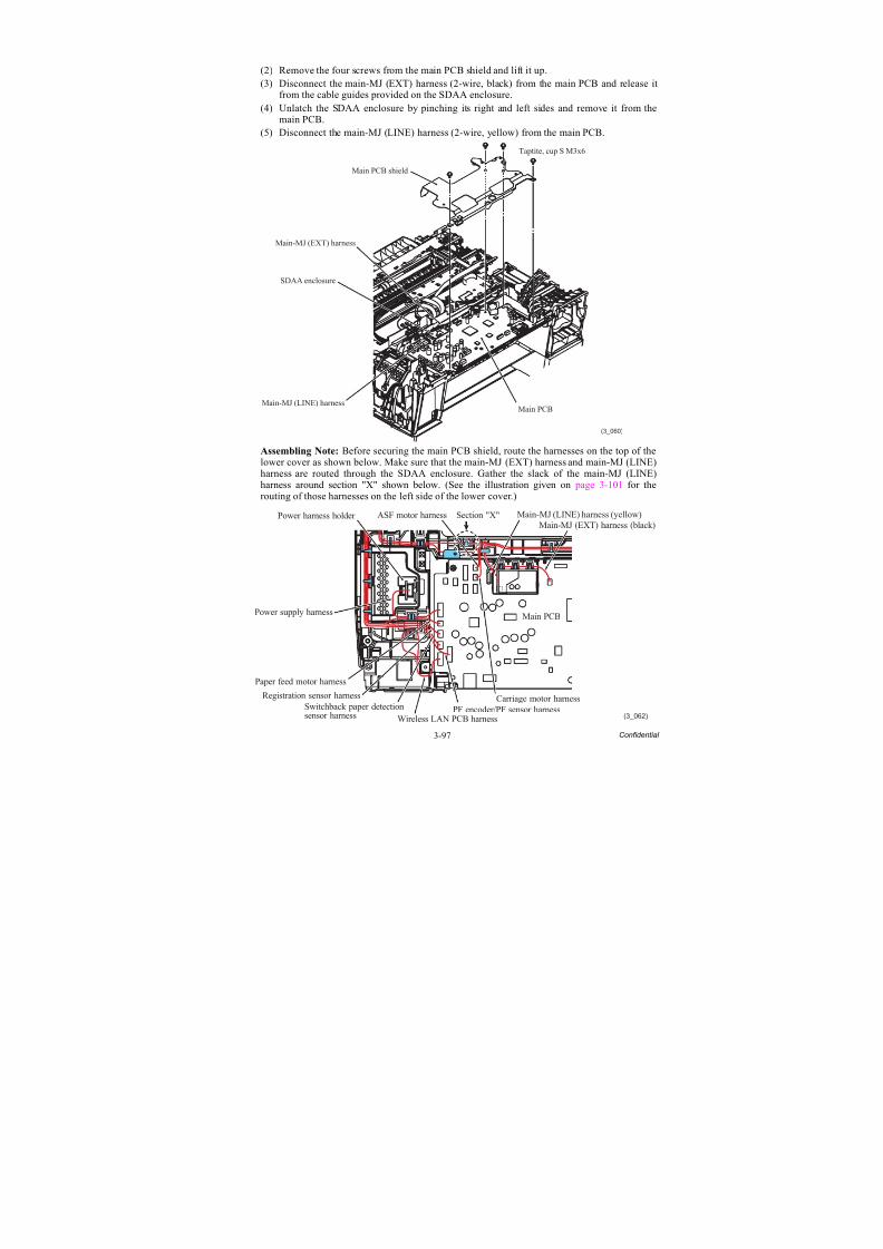
8/15/2019 Brother MFC 6510dw Sm
http://slidepdf.com/reader/full/brother-mfc-6510dw-sm 222/392
3-97 Confidential
(2) Remove the four screws from the main PCB shield and lift it up.(3) Disconnect the main-MJ (EXT) harness (2-wire, black) from the main PCB and release it
from the cable guides provided on the SDAA enclosure.
(4) Unlatch the SDAA enclosure by pinching its right and left sides and remove it from themain PCB.
(5) Disconnect the main-MJ (LINE) harness (2-wire, yellow) from the main PCB.
Assembling Note: Before securing the main PCB shield, route the harnesses on the top of thelower cover as shown below. Make sure that the main-MJ (EXT) harness and main-MJ (LINE)harness are routed through the SDAA enclosure. Gather the slack of the main-MJ (LINE)harness around section "X" shown below. (See the illustration given on page 3-101 for therouting of those harnesses on the left side of the lower cover.)
(3_060)
Main PCB
Taptite, cup S M3x6
Main PCB shield
Main-MJ (EXT) harness
Main-MJ (LINE) harness
SDAA enclosure
(3_062)
ASF motor harness
Power supply harness
Paper feed motor harness
Registration sensor harness
Switchback paper detectionsensor harness Wireless LAN PCB harness
PF encoder/PF sensor harnessCarriage motor harness
Main PCB
Main-MJ (EXT) harness (black)
Main-MJ (LINE) harness (yellow)Power harness holder Section "X"

8/15/2019 Brother MFC 6510dw Sm
http://slidepdf.com/reader/full/brother-mfc-6510dw-sm 223/392
3-98 Confidential
(6) Remove screw "a" from the main PCB, then lift up the PCB.
(7) Remove two screws "b" (that secure the MJ/PS shield unit together) from the main PCBshield frame, then lift up the shield frame.
"a": Taptite, cup S M3x6"b": Screw, bind M3x6
Assembling Note: If you replace the main PCB, you need to load programs onto the flashROM, restore the machine information and head calibration data that have been backed up in an
external memory, and make specified adjustments of various settings (refer to Chapter 4,Section 4.2). Before starting, make sure that the head/carriage unit is mounted.
(3_061)
SDAA enclosure
"a"
(which secure themain PCB shieldframe together
with the MJ/PSshield unit.)
Main PCB
Main PCB shield frame
Lower cover
"b"
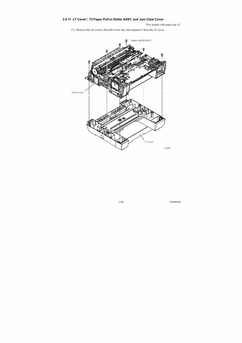
8/15/2019 Brother MFC 6510dw Sm
http://slidepdf.com/reader/full/brother-mfc-6510dw-sm 224/392
3-99 Confidential
3.9.11 LT Cover*, T2 Paper Pull-in Roller ASSY, and Jam Clear Cover
*For models with paper tray #2
(1) Remove the six screws from the lower tray and separate it from the LT cover.
(3_063)
Lower cover
LT cover
Taptite, bind B M4x12
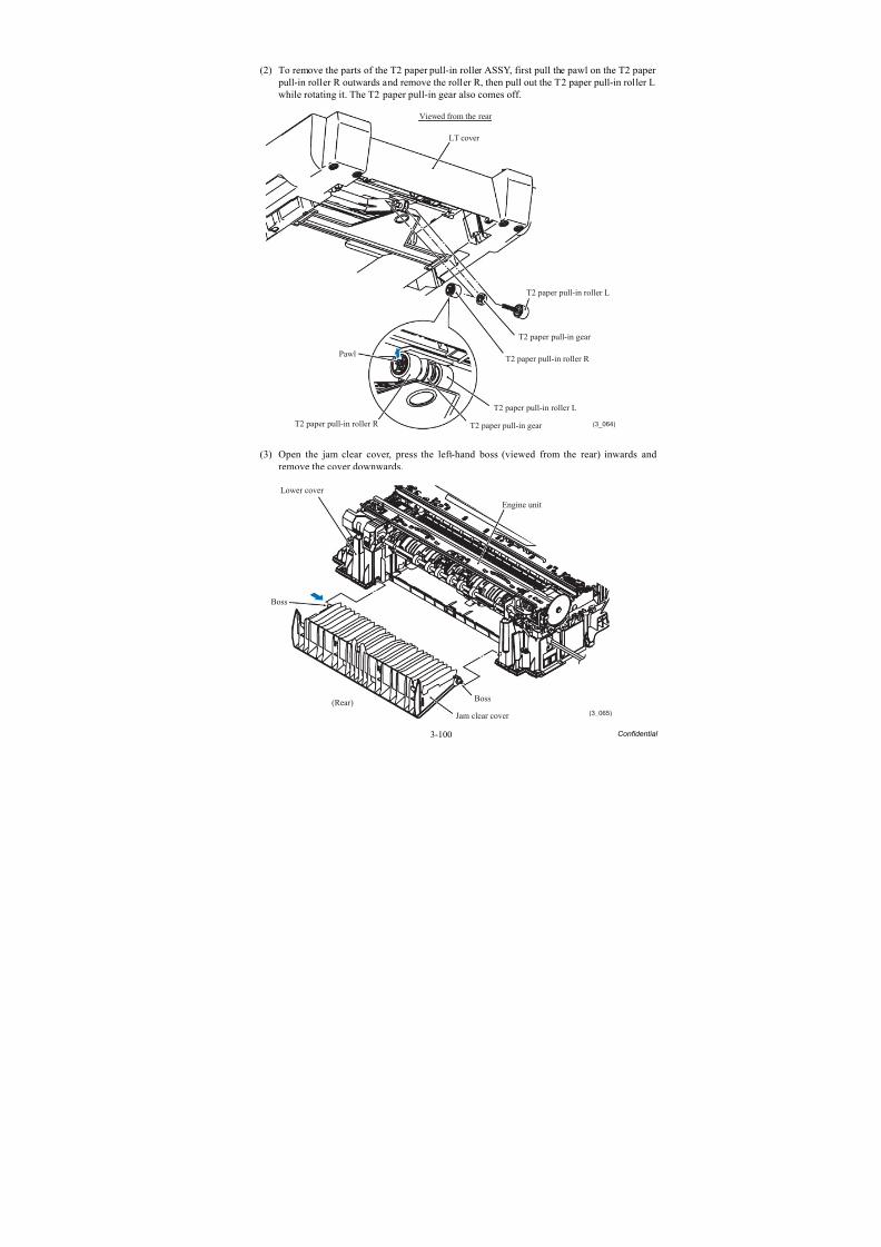
8/15/2019 Brother MFC 6510dw Sm
http://slidepdf.com/reader/full/brother-mfc-6510dw-sm 225/392
3-100 Confidential
(2) To remove the parts of the T2 paper pull-in roller ASSY, first pull the pawl on the T2 paper pull-in roller R outwards and remove the roller R, then pull out the T2 paper pull-in roller Lwhile rotating it. The T2 paper pull-in gear also comes off.
(3) Open the jam clear cover, press the left-hand boss (viewed from the rear) inwards andremove the cover downwards.
(3_064)
T2 paper pull-in roller L
LT cover
Viewed from the rear
Pawl
T2 paper pull-in roller R T2 paper pull-in gear
T2 paper pull-in roller L
T2 paper pull-in roller R
T2 paper pull-in gear
(3_065)
Engine unit
Lower cover
Boss
(Rear)
Jam clear cover
Boss

8/15/2019 Brother MFC 6510dw Sm
http://slidepdf.com/reader/full/brother-mfc-6510dw-sm 226/392
3-101 Confidential
3.9.12 MJ/PS Shield Unit (MJ PCB and Power Supply PCB)
(1) If the main PCB shield frame has not been removed, disconnect the power supply harness,main-MJ (LINE) harness and main-MJ (EXT) harness from the main PCB, then removetwo screws ("b" shown on page 3-98) from the main PCB shield frame.
(2) Unlatch the power harness holder and take it off the power supply shield.
(3) Disconnect the power supply harness from the power supply PCB.
(4) Remove the two screws ("c" and "d" shown in the figure below).
(5) Release the harnesses from the cable guides provided on the lower cover.
(6) As shown below, press lock "x" on the MJ/PS shield unit to release it from pawl "y" on thelower cover, then remove the MJ/PS shield unit from the bottom of the lower cover.
(3_066)
"c"
"d"
Lower cover
Main-MJ (LINE)harness (yellow)
Main-MJ (EXT)
harness (black)
MJ/PS shield unit
Lock "x"
Lower cover
Pawl "y" providedon the lowercover
Lock "x"
Press lock "x"inwards to releaseit from pawl"y" provided onthe lower cover.
Pawl "y"
Power supply harness
Latch
Power harness holder
Power supply shield
Power supplyPCB
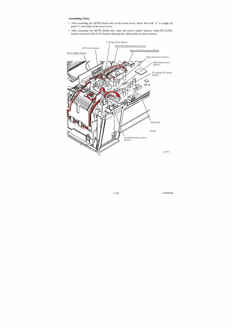
8/15/2019 Brother MFC 6510dw Sm
http://slidepdf.com/reader/full/brother-mfc-6510dw-sm 227/392
3-102 Confidential
Assembling Notes:
• After mounting the MJ/PS shield unit on the lower cover, check that lock "x" is caught on pawl "y" provided on the lower cover.
• After mounting the MJ/PS shield unit, route the power supply harness, main-MJ (LINE)harness and main-MJ (EXT) harness through the cable guides as shown below.
(3_071)
Switchback paper sensorharness
Power supply harness
ASF motor harness
Carriage motor harness
Paper feed motor harness
PF encoder/PF sensorharness
Main PCB
Main-MJ (EXT) harness (black)
Main-MJ (LINE) harness (yellow)
Registration sensor harness
(Front)
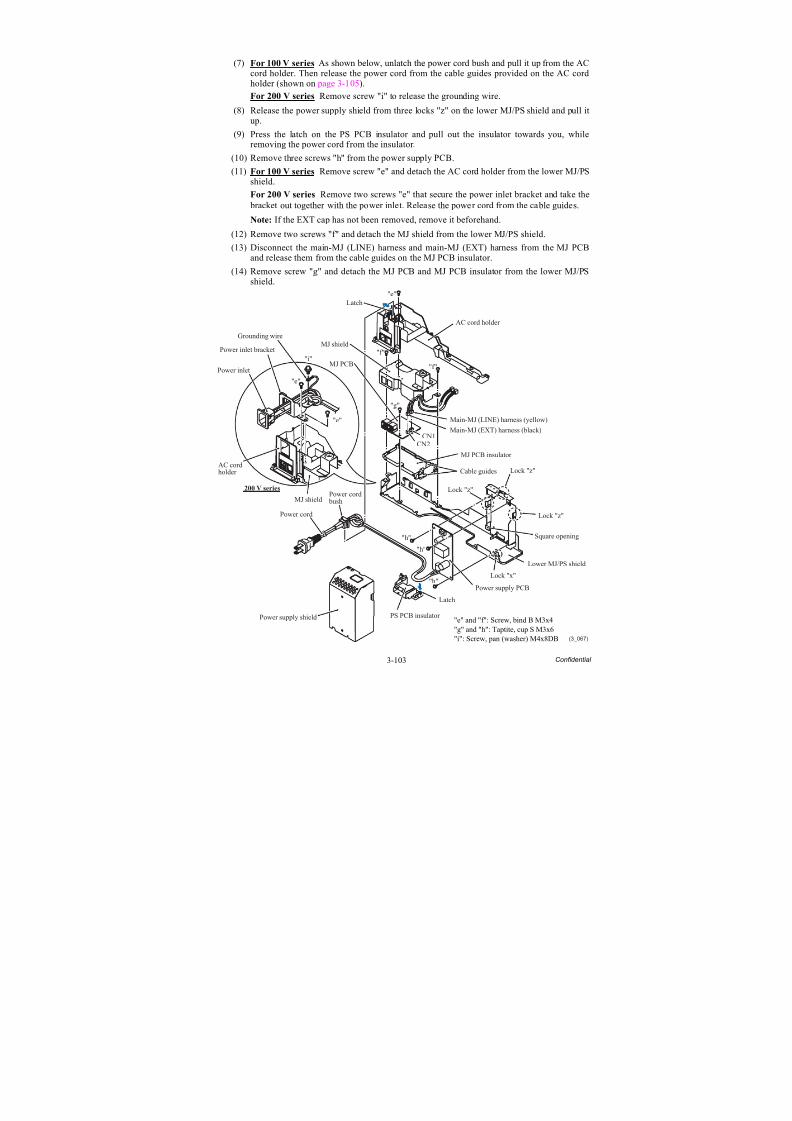
8/15/2019 Brother MFC 6510dw Sm
http://slidepdf.com/reader/full/brother-mfc-6510dw-sm 228/392
3-103 Confidential
(7) For 100 V series As shown below, unlatch the power cord bush and pull it up from the ACcord holder. Then release the power cord from the cable guides provided on the AC cordholder (shown on page 3-105).
For 200 V series Remove screw "i" to release the grounding wire.
(8) Release the power supply shield from three locks "z" on the lower MJ/PS shield and pull itup.
(9) Press the latch on the PS PCB insulator and pull out the insulator towards you, whileremoving the power cord from the insulator.
(10) Remove three screws "h" from the power supply PCB.
(11) For 100 V series Remove screw "e" and detach the AC cord holder from the lower MJ/PSshield.
For 200 V series Remove two screws "e" that secure the power inlet bracket and take the bracket out together with the power inlet. Release the power cord from the cable guides.
Note: If the EXT cap has not been removed, remove it beforehand.
(12) Remove two screws "f" and detach the MJ shield from the lower MJ/PS shield.
(13) Disconnect the main-MJ (LINE) harness and main-MJ (EXT) harness from the MJ PCBand release them from the cable guides on the MJ PCB insulator.
(14) Remove screw "g" and detach the MJ PCB and MJ PCB insulator from the lower MJ/PSshield.
(3_067)
"e"Latch
AC cord holder
"f"
"f"MJ shield
"g"
Main-MJ (LINE) harness (yellow)
Main-MJ (EXT) harness (black)
MJ PCB
CN1CN2
MJ PCB insulator
Cable guides
Power cord
bushPower cord
Power supply shield
"h"
"h"
"h"
Latch
PS PCB insulator
Power supply PCB
Lock "x"
Lower MJ/PS shield
Lock "z"
Square opening
Lock "z"
Lock "z"
"i"
"e"
"e"
Grounding wire
Power inlet bracket
Power inlet
AC cordholder
MJ shield
200 V series
"e" and "f": Screw, bind B M3x4
"g" and "h": Taptite, cup S M3x6"i": Screw, pan (washer) M4x8DB
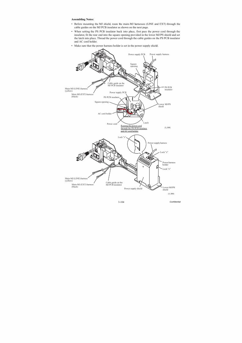
8/15/2019 Brother MFC 6510dw Sm
http://slidepdf.com/reader/full/brother-mfc-6510dw-sm 229/392
3-104 Confidential
Assembling Notes:
• Before mounting the MJ shield, route the main-MJ harnesses (LINE and EXT) through thecable guides on the MJ PCB insulator as shown on the next page.
• When setting the PS PCB insulator back into place, first pass the power cord through theinsulator, fit the rear end into the square opening provided in the lower MJ/PS shield and set
the latch into place. Thread the power cord through the cable guides on the PS PCB insulator and AC cord holder.
• Make sure that the power harness holder is set in the power supply shield.
(3_068)
Power cord
Power supply harness
PS PCB insulator
PS PCBinsulator
Power supply PCB
Power supply PCB
Squareopening
Lower MJ/PSshield
Main-MJ (LINE) harness(yellow)
Main-MJ (EXT) harness(black)
Cable guide on theMJ PCB insulator
AC cord holder
Routing the power cord
through the PS PCB insulator
and AC cord holder
Square opening
Latch
(3_069)
Power supply harness
Lower MJ/PSshield
Main-MJ (LINE) harness(yellow)
Main-MJ (EXT) harness(black)
Power supply shield
Lock "z"
Lock "z"
Lock "z"
Cable guide on theMJ PCB insulator
Power harnessholder
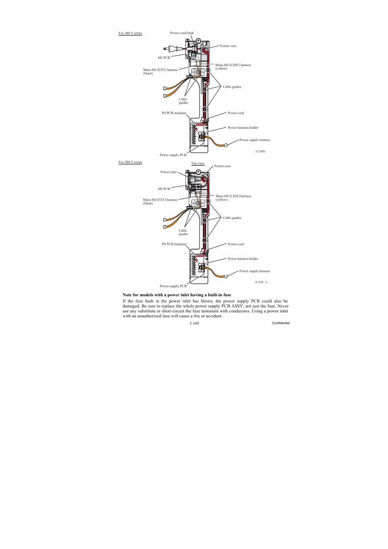
8/15/2019 Brother MFC 6510dw Sm
http://slidepdf.com/reader/full/brother-mfc-6510dw-sm 230/392
3-105 Confidential
Note for models with a power inlet having a built-in fuse
If the fuse built in the power inlet has blown, the power supply PCB could also be
damaged. Be sure to replace the whole power supply PCB ASSY, not just the fuse. Never use any substitute or short-circuit the fuse terminals with conductors. Using a power inletwith an unauthorized fuse will cause a fire or accident.
(3_070)
Power cord bush
MJ PCB
Main-MJ (EXT) harness(black)
Main-MJ (LINE) harness(yellow)
Cableguides
PS PCB insulator
Power supply PCB
Power supply harness
Power cord
Cable guides
Ferrite core
Power harness holder
For 100 V series
(3_070_1)
MJ PCB
Cableguides
PS PCB insulator
Power supply PCB
Power supply harness
Power cord
Power harness holder
Cable guides
Ferrite coreTop viewFor 200 V series
Power inlet
Main-MJ (EXT) harness(black)
Main-MJ (LINE) harness(yellow)
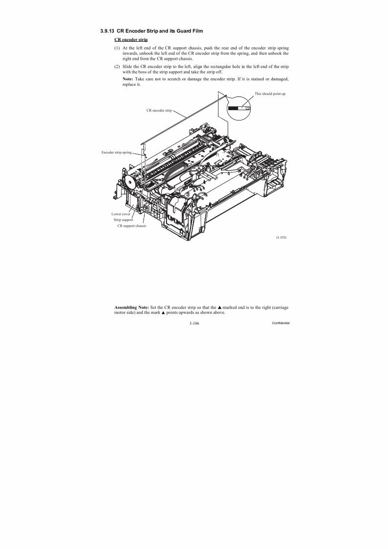
8/15/2019 Brother MFC 6510dw Sm
http://slidepdf.com/reader/full/brother-mfc-6510dw-sm 231/392
3-106 Confidential
3.9.13 CR Encoder Strip and its Guard Film
CR encoder strip
(1) At the left end of the CR support chassis, push the rear end of the encoder strip springinwards, unhook the left end of the CR encoder strip from the spring, and then unhook theright end from the CR support chassis.
(2) Slide the CR encoder strip to the left, align the rectangular hole in the left end of the stripwith the boss of the strip support and take the strip off.
Note: Take care not to scratch or damage the encoder strip. If it is stained or damaged,replace it.
Assembling Note: Set the CR encoder strip so that the -marked end is to the right (carriagemotor side) and the mark points upwards as shown above.
(3_072)
CR support chassis
CR encoder strip
Encoder strip spring
Lower cover
Strip support
This should point up.
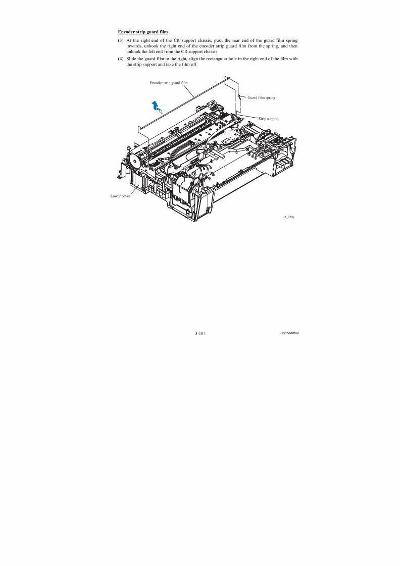
8/15/2019 Brother MFC 6510dw Sm
http://slidepdf.com/reader/full/brother-mfc-6510dw-sm 232/392
3-107 Confidential
Encoder strip guard film
(3) At the right end of the CR support chassis, push the rear end of the guard film springinwards, unhook the right end of the encoder strip guard film from the spring, and thenunhook the left end from the CR support chassis.
(4) Slide the guard film to the right, align the rectangular hole in the right end of the film with
the strip support and take the film off.
(3_073)
Encoder strip guard film
Lower cover
Strip support
Guard film spring
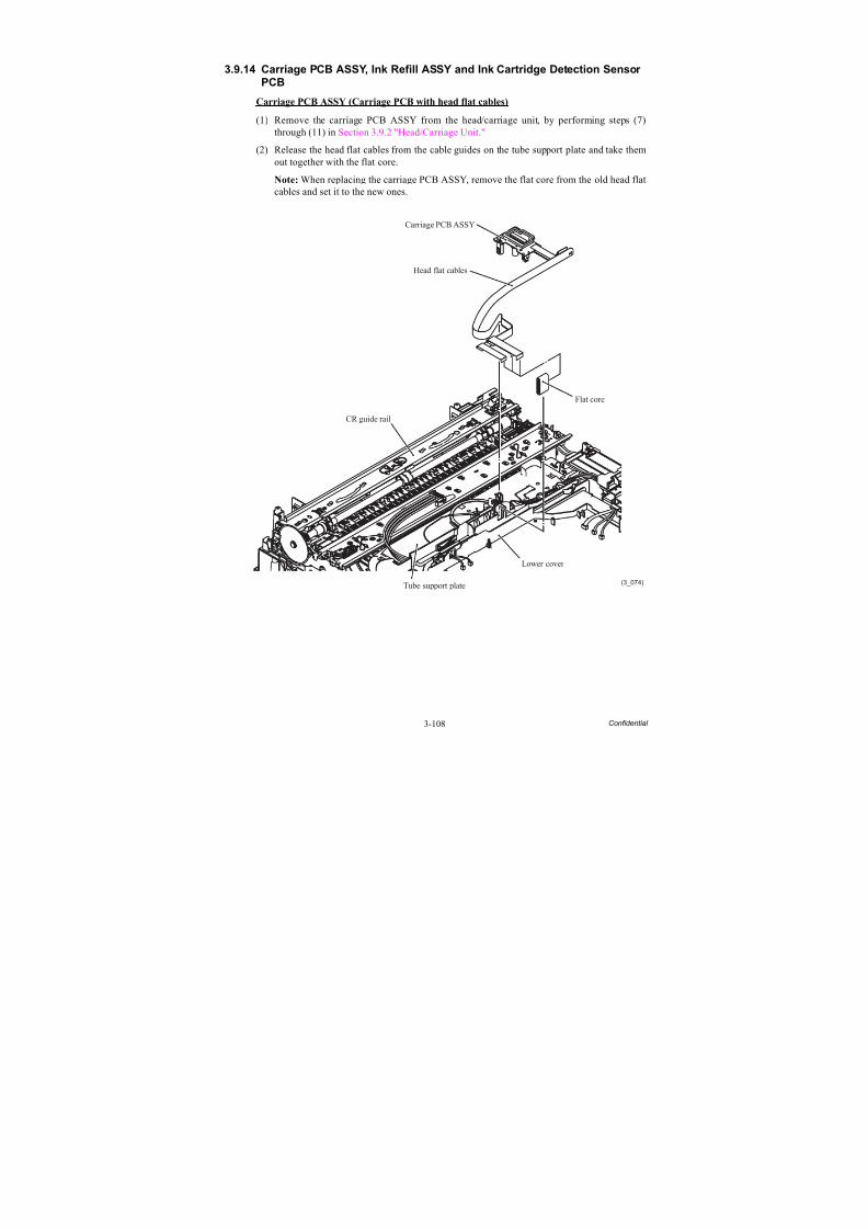
8/15/2019 Brother MFC 6510dw Sm
http://slidepdf.com/reader/full/brother-mfc-6510dw-sm 233/392
3-108 Confidential
3.9.14 Carriage PCB ASSY, Ink Refill ASSY and Ink Cartridge Detection SensorPCB
Carriage PCB ASSY (Carriage PCB with head flat cables)
(1) Remove the carriage PCB ASSY from the head/carriage unit, by performing steps (7)through (11) in Section 3.9.2 "Head/Carriage Unit."
(2) Release the head flat cables from the cable guides on the tube support plate and take themout together with the flat core.
Note: When replacing the carriage PCB ASSY, remove the flat core from the old head flatcables and set it to the new ones.
(3_074)
Lower cover
Carriage PCB ASSY
Head flat cables
CR guide rail
Tube support plate
Flat core
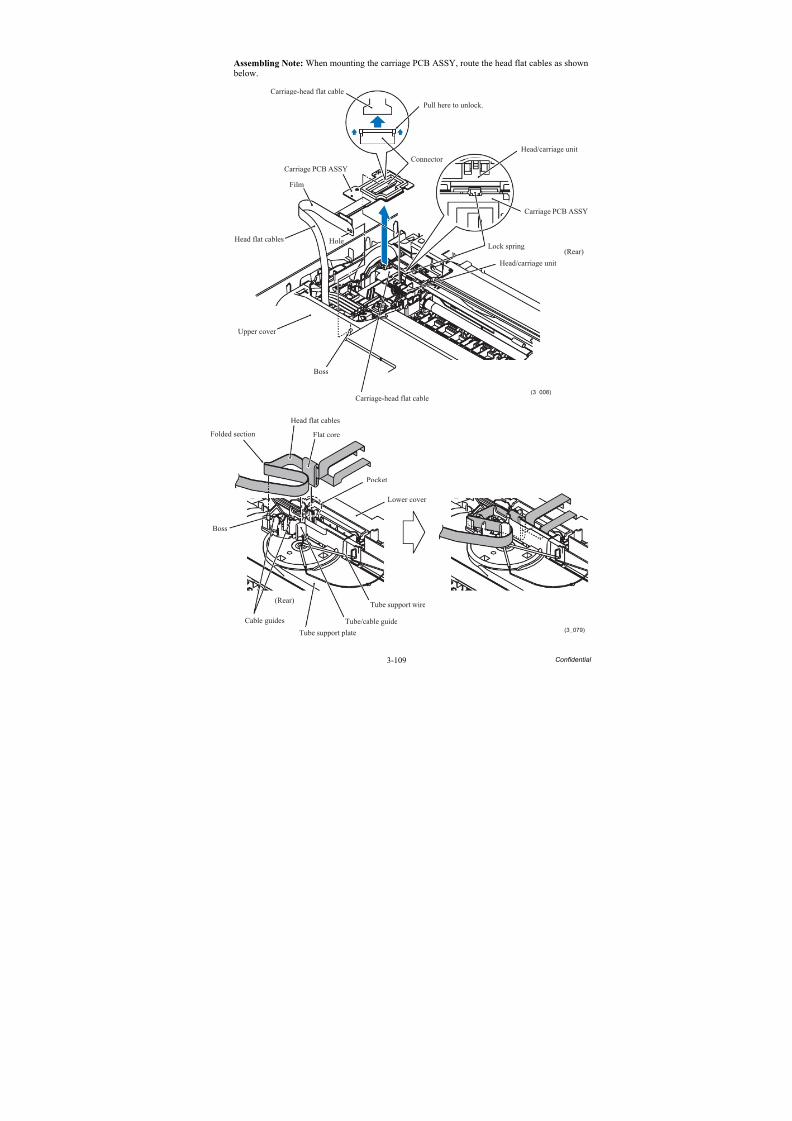
8/15/2019 Brother MFC 6510dw Sm
http://slidepdf.com/reader/full/brother-mfc-6510dw-sm 234/392
3-109 Confidential
Assembling Note: When mounting the carriage PCB ASSY, route the head flat cables as shown below.
(3_008)
Carriage PCB ASSY
Carriage PCB ASSY
HoleHead flat cables
Upper cover
Boss
Carriage-head flat cable
Head/carriage unit
Head/carriage unit
Lock spring(Rear)
Connector
Film
Pull here to unlock.
Carriage-head flat cable
(3_079)
Head flat cables
Flat coreFolded section
Boss
Cable guides
(Rear)
Tube support plate
Tube/cable guide
Tube support wire
Lower cover
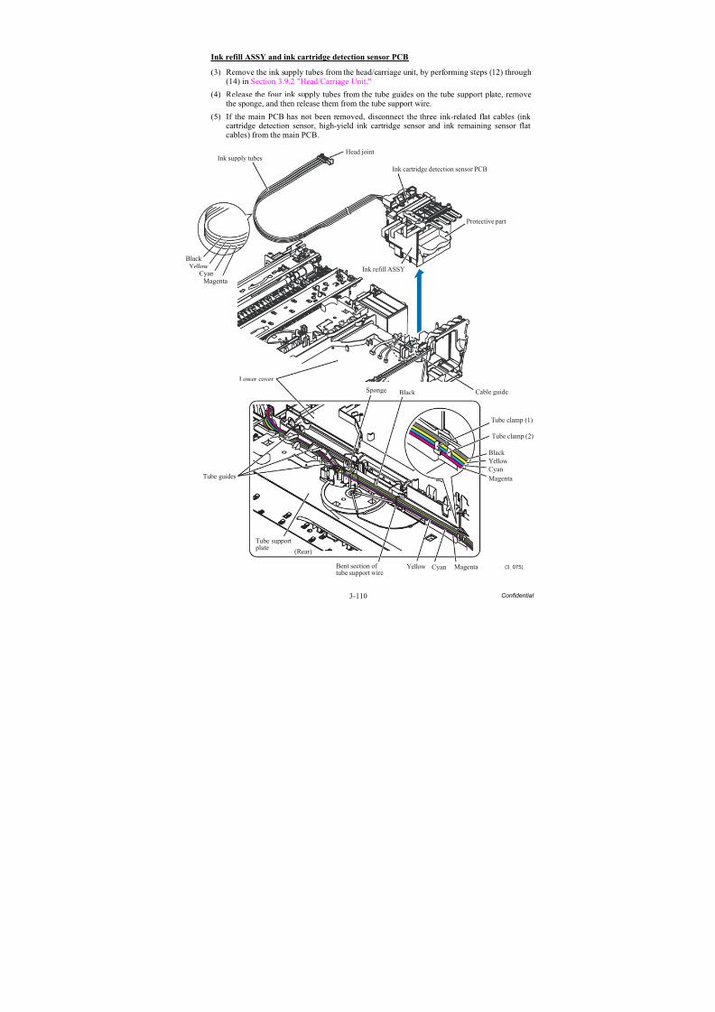
8/15/2019 Brother MFC 6510dw Sm
http://slidepdf.com/reader/full/brother-mfc-6510dw-sm 235/392
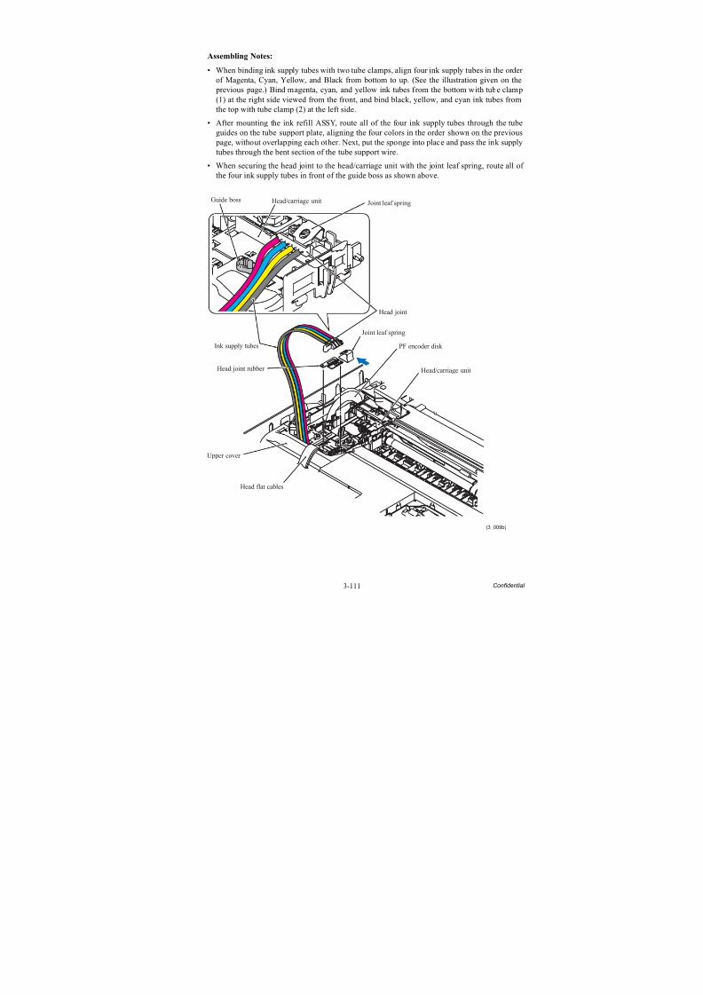
8/15/2019 Brother MFC 6510dw Sm
http://slidepdf.com/reader/full/brother-mfc-6510dw-sm 236/392
3-111 Confidential
Assembling Notes:
• When binding ink supply tubes with two tube clamps, align four ink supply tubes in the order of Magenta, Cyan, Yellow, and Black from bottom to up. (See the illustration given on the previous page.) Bind magenta, cyan, and yellow ink tubes from the bottom with tube clamp(1) at the right side viewed from the front, and bind black, yellow, and cyan ink tubes from
the top with tube clamp (2) at the left side.• After mounting the ink refill ASSY, route all of the four ink supply tubes through the tube
guides on the tube support plate, aligning the four colors in the order shown on the previous page, without overlapping each other. Next, put the sponge into place and pass the ink supplytubes through the bent section of the tube support wire.
• When securing the head joint to the head/carriage unit with the joint leaf spring, route all of the four ink supply tubes in front of the guide boss as shown above.
Joint leaf spring
Joint leaf spring
(3_009b)
Head joint
Upper cover
Head flat cables
Head/carriage unit
Head/carriage unit
PF encoder disk
Head joint rubber
Ink supply tubes
Guide boss
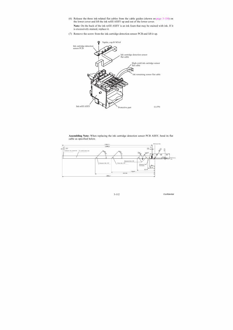
8/15/2019 Brother MFC 6510dw Sm
http://slidepdf.com/reader/full/brother-mfc-6510dw-sm 237/392
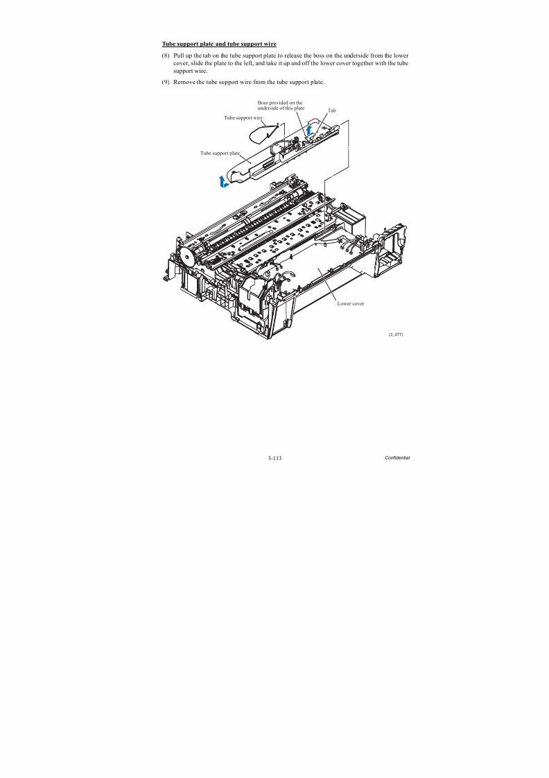
8/15/2019 Brother MFC 6510dw Sm
http://slidepdf.com/reader/full/brother-mfc-6510dw-sm 238/392
3-113 Confidential
Tube support plate and tube support wire
(8) Pull up the tab on the tube support plate to release the boss on the underside from the lower cover, slide the plate to the left, and take it up and off the lower cover together with the tubesupport wire.
(9) Remove the tube support wire from the tube support plate.
(3_077)
Lower cover
Tube support plate
Tube support wire
Tab
Boss provided on theunderside of this plate
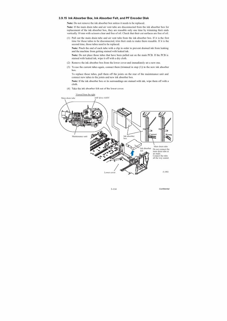
8/15/2019 Brother MFC 6510dw Sm
http://slidepdf.com/reader/full/brother-mfc-6510dw-sm 239/392
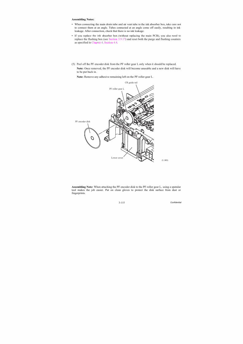
8/15/2019 Brother MFC 6510dw Sm
http://slidepdf.com/reader/full/brother-mfc-6510dw-sm 240/392
3-115 Confidential
Assembling Notes:
• When connecting the main drain tube and air vent tube to the ink absorber box, take care notto connect them at an angle. Tubes connected at an angle come off easily, resulting in ink leakage. After connection, check that there is no ink leakage.
• If you replace the ink absorber box (without replacing the main PCB), you also need to
replace the flushing box (see Section 3.9.17) and reset both the purge and flushing countersas specified in Chapter 4, Section 4.4.
(5) Peel off the PF encoder disk from the PF roller gear L only when it should be replaced.
Note: Once removed, the PF encoder disk will become unusable and a new disk will haveto be put back in.
Note: Remove any adhesive remaining left on the PF roller gear L.
Assembling Note: When attaching the PF encoder disk to the PF roller gear L, using a spatular tool makes the job easier. Put on clean gloves to protect the disk surface from dust or
fingerprints.
(3_083)
CR guide rail
PF roller gear L
PF encoder disk
Lower cover
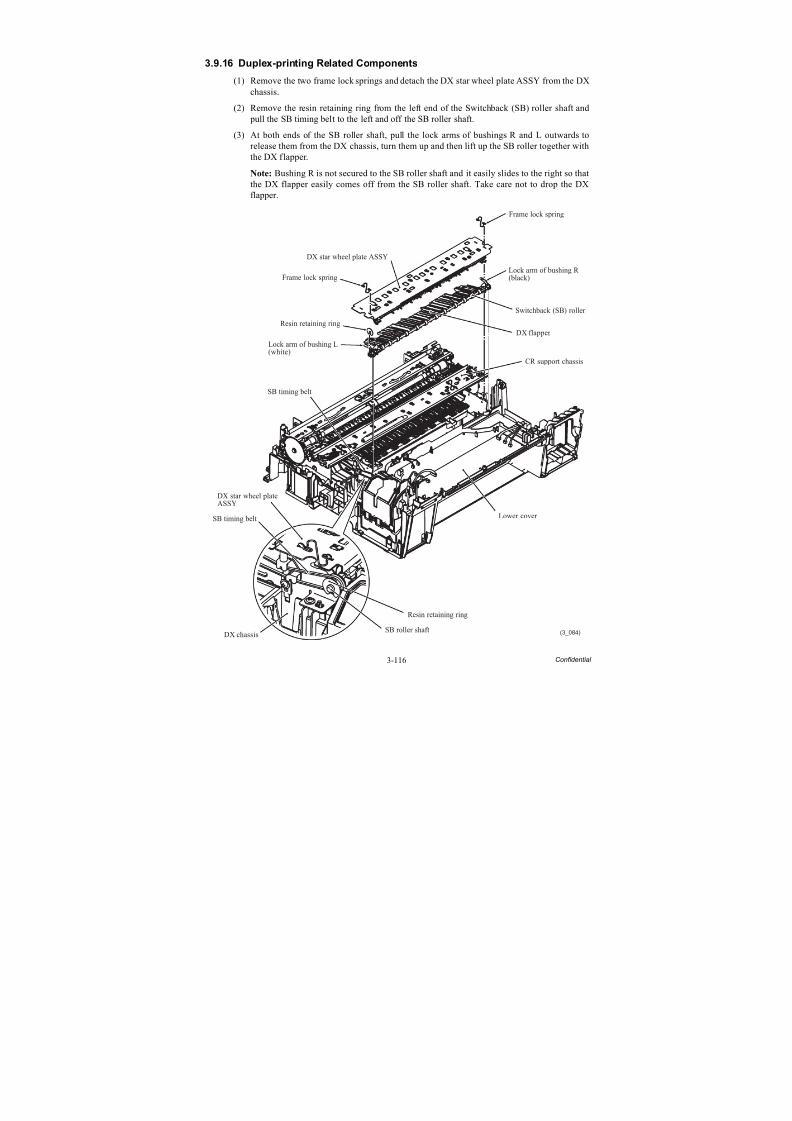
8/15/2019 Brother MFC 6510dw Sm
http://slidepdf.com/reader/full/brother-mfc-6510dw-sm 241/392
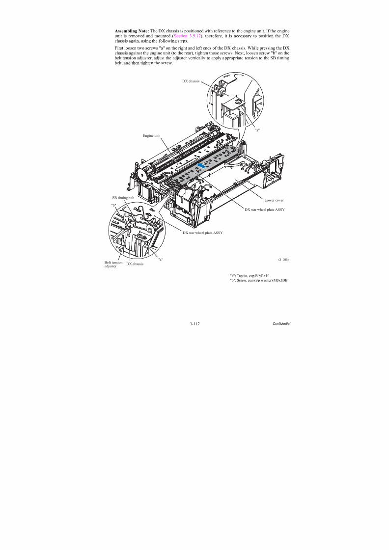
8/15/2019 Brother MFC 6510dw Sm
http://slidepdf.com/reader/full/brother-mfc-6510dw-sm 242/392
3-117 Confidential
Assembling Note: The DX chassis is positioned with reference to the engine unit. If the engineunit is removed and mounted (Section 3.9.17), therefore, it is necessary to position the DXchassis again, using the following steps.
First loosen two screws "a" on the right and left ends of the DX chassis. While pressing the DXchassis against the engine unit (to the rear), tighten those screws. Next, loosen screw "b" on the belt tension adjuster, adjust the adjuster vertically to apply appropriate tension to the SB timing
belt, and then tighten the screw.
"a": Taptite, cup B M3x10"b": Screw, pan (s/p washer) M3x5DB
DX chassis
(3_085)
Engine unit
DX chassisBelt tensionadjuster
SB timing belt
"a"
"b"DX star wheel plate ASSY
DX star wheel plate ASSY
Lower cover
"a"
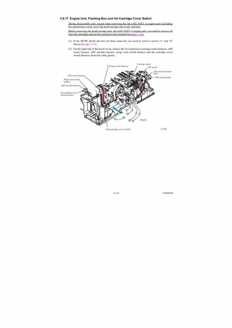
8/15/2019 Brother MFC 6510dw Sm
http://slidepdf.com/reader/full/brother-mfc-6510dw-sm 243/392
3-118 Confidential
3.9.17 Engine Unit, Flashing Box and Ink Cartridge Cover Switch
During disassembly jobs, except when removing the ink refill ASSY or engine unit (includingthe maintenance unit), leave the head/carriage unit in the machine.
Before removing the head/carriage unit, ink refill ASSY or engine unit, you need to remove allfour ink cartridges and set the protective part instead (see page 3-36).
(1) If the MJ/PS shield unit has not been removed, you need to remove screws "c" and "d"shown on page 3-101.
(2) On the right end of the lower cover, release the five harnesses (carriage motor harness, ASFmotor harness, ASF encoder harness, purge cam switch harness and ink cartridge cover switch harness) from the cable guides.
Carriage motor
(3_087)
Carriage motor harness
ASF motor harness
Purge cam switchharness
ASF encoder harness
Ink cartridge coverswitch harness
(Ink cartridge cover switch)
(Right)
ASF encoder disk
ASF motor/encoder
PCB
ASF motor
8/15/2019 Brother MFC 6510dw Sm
http://slidepdf.com/reader/full/brother-mfc-6510dw-sm 244/392
3-119 Confidential
(3) Remove the SB timing belt from the left end of the engine unit.
(4) On the left end of the lower cover, release the four harnesses (paper feed motor harness, PFencoder/PF sensor harness, registration sensor harness and switchback paper sensor harness) from the cable guides.
(5) Remove the two screws from the engine unit.
(6) Lift the engine unit up and out of the lower cover in the direction of the arrow shown below, holding the inner chute located beneath the CR guide rail.
Note: Do not hold the CR guide rail.
Note: Take care not to touch the PF encoder disk.
Note: If the ink absorber box does not need to be replaced, be sure to take it out of thelower cover together with the engine unit. If the main drain tube and air vent tube aredisconnected from the ink absorber box, they are reusable only one time by trimming their ends vertically 10 mm with scissors clear and free of oil. Check that their cut surfaces arefree of oil. If it is the second time for those tubes to be disconnected, they need to bereplaced.
Note: Do not place the engine unit directly on a flat surface; doing so may break the PFencoder disk and gears. Be sure to place a support pad under the engine unit as shown below.
(7) Take the flushing box and ink absorber felt out of the lower cover.
(3_088)
Engine unit
Taptite, cup BM3x10
PF encoder disk
Paper feedmotor harness
Registrationsensor harness
PF encoder/PF sensor harness
SB timing belt
Flushing box
Switchback paperdetection sensorharness
(Front)
Lower cover
Ink absorber felt
Carriage motor harnessPurge cam switch harness
ASF motor harnessASF encoder harness ASF motor/encoder harness
PF encoder disk
Engine unit
Support pad
8/15/2019 Brother MFC 6510dw Sm
http://slidepdf.com/reader/full/brother-mfc-6510dw-sm 245/392
3-120 Confidential
(8) Remove the ink cartridge cover switch from the front right side of the lower cover.
Assembling Notes:
• When mounting the engine unit on the lower cover, be careful not to crush the harnesses between the engine unit and the cover. Mount the engine unit parallel to the lower cover andtighten the screws securely.
• After mounting the engine unit, route the harnesses through the cable guides on the right andleft ends of the lower cover. (See the figure below and the next page.)
• If you replace the flushing box (without replacing the main PCB), you also need to replacethe ink absorber box (see Section 3.9.15) and reset both the flushing and purge counters asspecified in Chapter 4, Section 4.4.
• If you replace the engine unit, make adjustments specified in Chapter 4, Section 4.1.
• The DX chassis (Section 3.9.16) is positioned with reference to the engine unit. If the engineunit is removed and mounted, therefore, it is necessary to position the DX chassis again (see page 3-117).
(3_089)
(Front)
Lower cover
Ink cartridge cover switch
(3_086)
Carriage motor
Carriage motorharness
ASF motorharness
Purge camswitch harness
ASF encoderharness
Ink cartridgecover switchharness
Lower cover Ink cartridge cover switch
Ferrite core ofcarriage motor harness
(Right)
Purge cam switch harness
Ferrite core ofASF motor harness
ASF encoderharness
ASF motorharness
ASFmotor/encoderharness
ASF encoder disk
ASF motor/encoder PCB
ASF motor
8/15/2019 Brother MFC 6510dw Sm
http://slidepdf.com/reader/full/brother-mfc-6510dw-sm 246/392
3-121 Confidential
(3_090)
Paper feed motor harness
PF encoder disk CR guide rail
PF sensorharness
Registrationsensor harness
(Rear)
PF encoderharness
PF encoder/PF sensorharness
(Left)Lower cover
Lower cover
ASF motor harness
Carriage motor harness
Main PCB
PF encoder/PF sensorharness
Switchback paperdetectionsensor harness
Registration sensorharness
Paper feed motorharness
(Front)
Carriage motor harness
ASF encoder harness
Purge cam switch harness
Ink cartridge coverswitch harness
8/15/2019 Brother MFC 6510dw Sm
http://slidepdf.com/reader/full/brother-mfc-6510dw-sm 247/392
3-122 Confidential
3.9.18 Components on the Engine Unit(Earth spring, Maintenance unit, Carriage motor, CR support chassis, Star wheel holder,
Intermediate roller, Inner paper guide, Switchback paper sensor PCB ASSY, Platen, DX chute
roller holder ASSYs, Inner chute ASSY, Registration sensor PCB ASSY and actuator, PF
encoder/PF sensor harness unit and actuator, PF encoder disk, Paper feed motor, T1 paper
pull-in roller ASSY)
Earth spring
(1) Release the upper and lower ends of the earth spring from the CR guide rail and the ASFmotor, respectively.
Assembling Note: When mounting the earth spring, take care not to contaminate it with grease.
First hook the upper end on the CR guide rail and insert the lower end under the ASF motor.
The earth spring twines around the ASF motor by itself with the spring force. After mounting it,check that the earth spring is in contact with the metal part of the ASF motor.
(3_091)
CR guide rail
Maintenance unit
CR guide rail
ASF motor
Earth spring
Earth spring
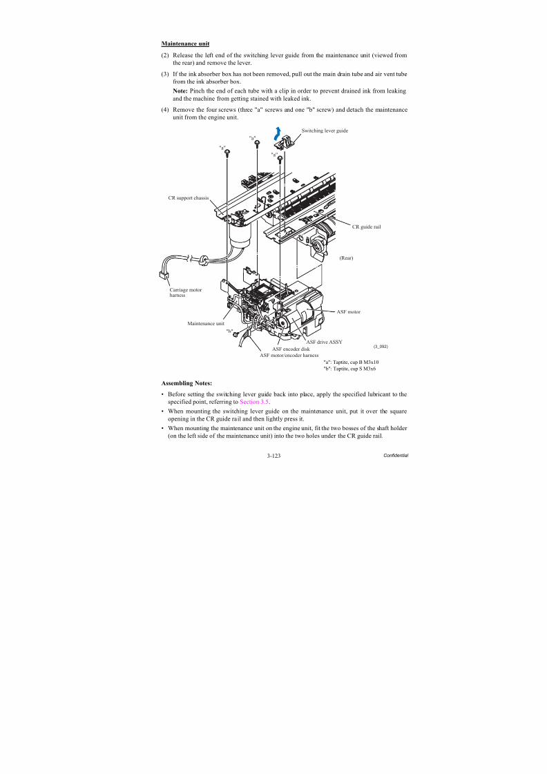
8/15/2019 Brother MFC 6510dw Sm
http://slidepdf.com/reader/full/brother-mfc-6510dw-sm 248/392
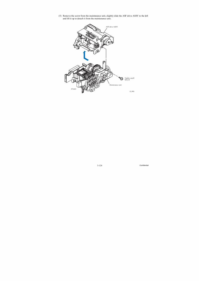
8/15/2019 Brother MFC 6510dw Sm
http://slidepdf.com/reader/full/brother-mfc-6510dw-sm 249/392
3-124 Confidential
(5) Remove the screw from the maintenance unit, slightly slide the ASF drive ASSY to the leftand lift it up to detach it from the maintenance unit.
(3_093)
ASF drive ASSY
Taptite, cup BM3x10
Maintenance unit
(Front)
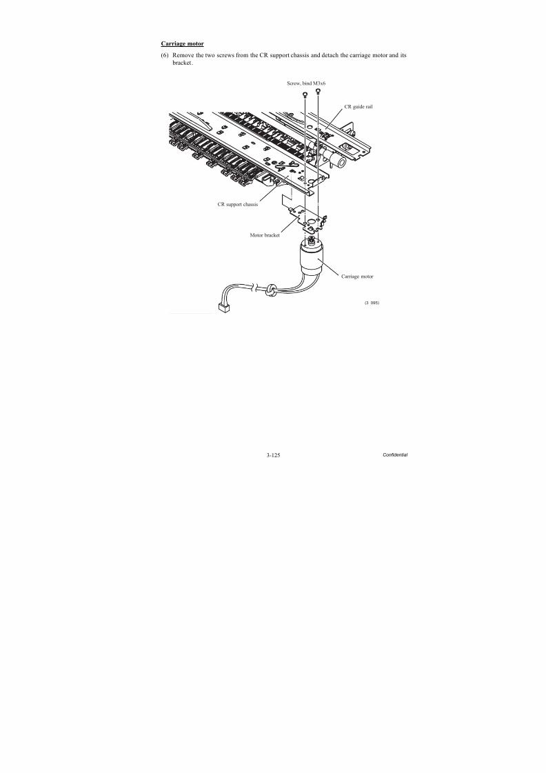
8/15/2019 Brother MFC 6510dw Sm
http://slidepdf.com/reader/full/brother-mfc-6510dw-sm 250/392
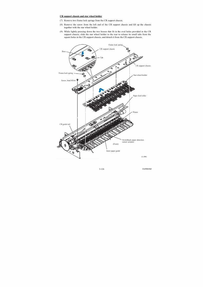
8/15/2019 Brother MFC 6510dw Sm
http://slidepdf.com/reader/full/brother-mfc-6510dw-sm 251/392
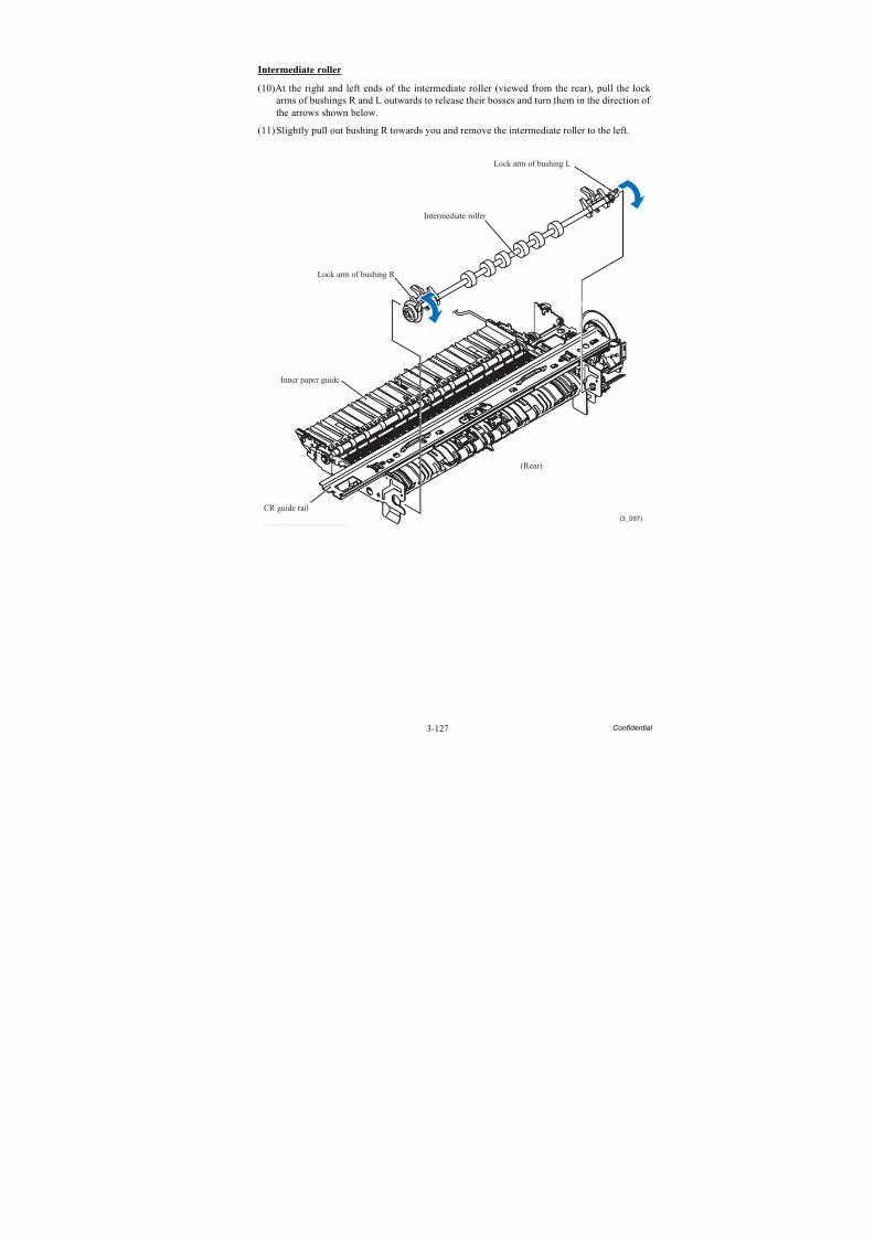
8/15/2019 Brother MFC 6510dw Sm
http://slidepdf.com/reader/full/brother-mfc-6510dw-sm 252/392
3-127 Confidential
Intermediate roller
(10)At the right and left ends of the intermediate roller (viewed from the rear), pull the lock arms of bushings R and L outwards to release their bosses and turn them in the direction of the arrows shown below.
(11)Slightly pull out bushing R towards you and remove the intermediate roller to the left.
(3_097)
Lock arm of bushing L
Intermediate roller
Lock arm of bushing R
(Rear)
CR guide rail
Inner paper guide
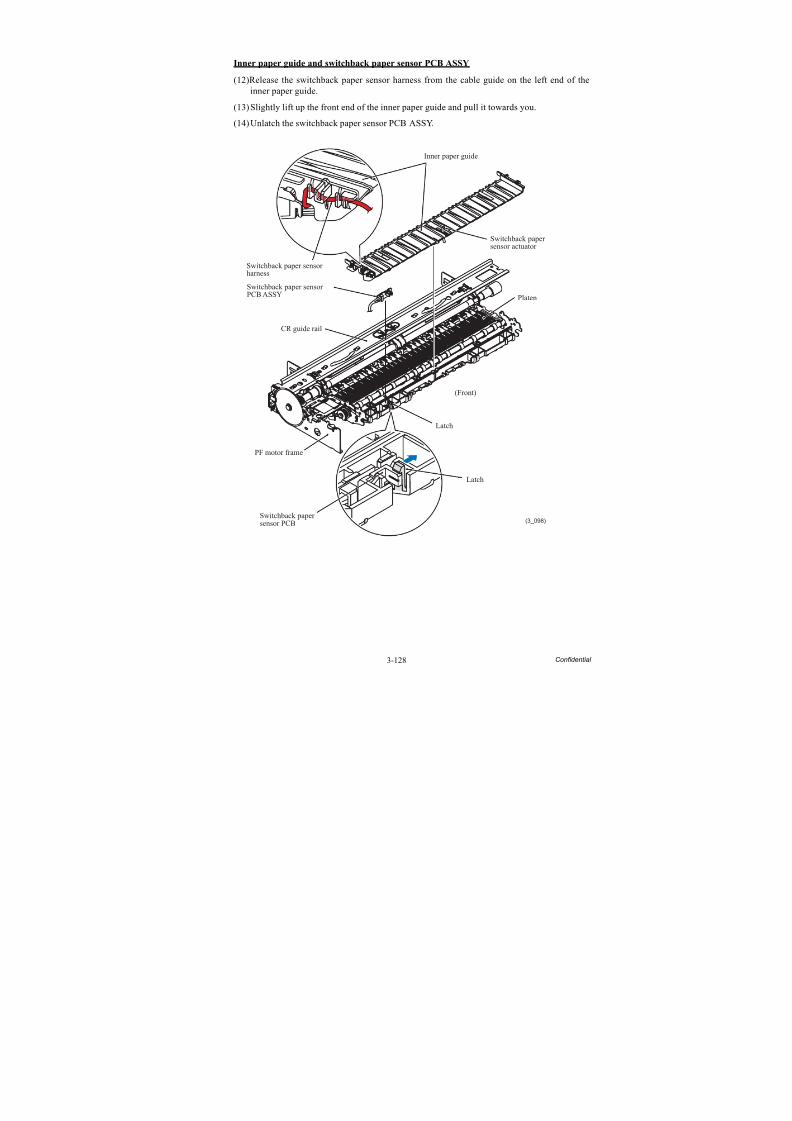
8/15/2019 Brother MFC 6510dw Sm
http://slidepdf.com/reader/full/brother-mfc-6510dw-sm 253/392
3-128 Confidential
Inner paper guide and switchback paper sensor PCB ASSY
(12)Release the switchback paper sensor harness from the cable guide on the left end of theinner paper guide.
(13)Slightly lift up the front end of the inner paper guide and pull it towards you.
(14)Unlatch the switchback paper sensor PCB ASSY.
(3_098)
Inner paper guide
Switchback paper sensorharness
Switchback paper sensorPCB ASSY
CR guide rail
PF motor frame
Switchback papersensor PCB
Latch
Latch
(Front)
Platen
Switchback papersensor actuator
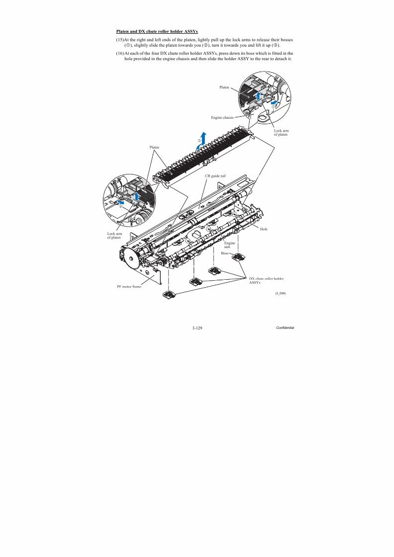
8/15/2019 Brother MFC 6510dw Sm
http://slidepdf.com/reader/full/brother-mfc-6510dw-sm 254/392
3-129 Confidential
Platen and DX chute roller holder ASSYs
(15)At the right and left ends of the platen, lightly pull up the lock arms to release their bosses(), slightly slide the platen towards you (), turn it towards you and lift it up ().
(16)At each of the four DX chute roller holder ASSYs, press down its boss which is fitted in thehole provided in the engine chassis and then slide the holder ASSY to the rear to detach it.
(3_099)
Platen
Platen
Lock armof platen
PF motor frame
Engineunit
CR guide rail
Lock armof platen
Engine chassis
Hole
Boss
DX chute roller holderASSYs
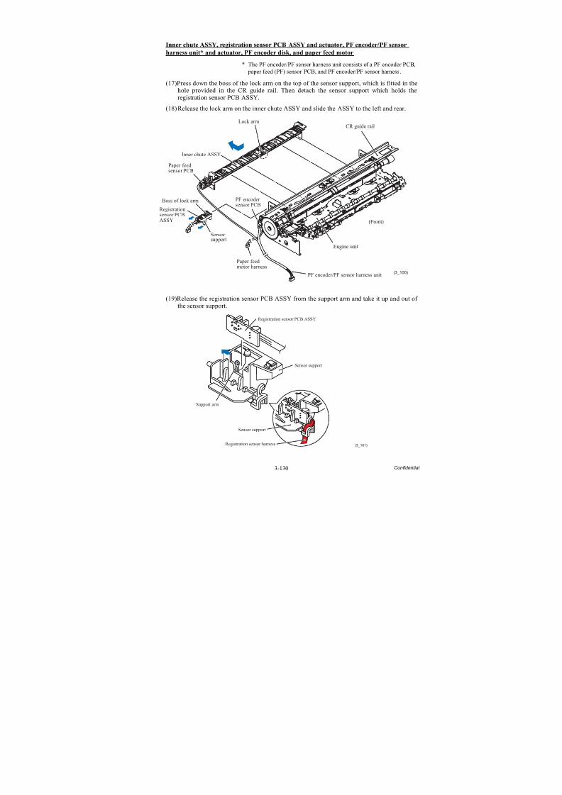
8/15/2019 Brother MFC 6510dw Sm
http://slidepdf.com/reader/full/brother-mfc-6510dw-sm 255/392
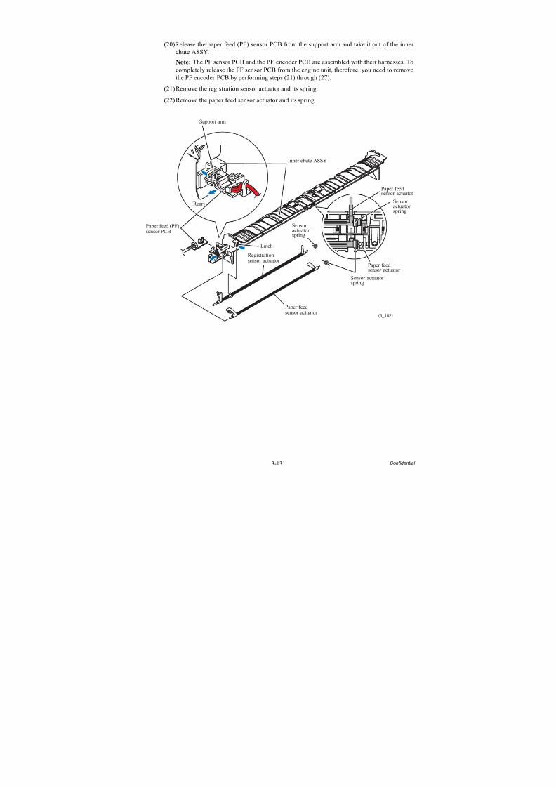
8/15/2019 Brother MFC 6510dw Sm
http://slidepdf.com/reader/full/brother-mfc-6510dw-sm 256/392
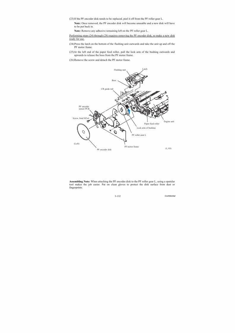
8/15/2019 Brother MFC 6510dw Sm
http://slidepdf.com/reader/full/brother-mfc-6510dw-sm 257/392
3-132 Confidential
(23) If the PF encoder disk needs to be replaced, peel it off from the PF roller gear L.
Note: Once removed, the PF encoder disk will become unusable and a new disk will haveto be put back in.
Note: Remove any adhesive remaining left on the PF roller gear L.
Performing steps (24) through (28) requires removing the PF encoder disk, so make a new disk ready for use.
(24)Press the latch on the bottom of the flushing unit outwards and take the unit up and off thePF motor frame.
(25)At the left end of the paper feed roller, pull the lock arm of the bushing outwards andupwards to release the boss from the PF motor frame.
(26)Remove the screw and detach the PF motor frame.
Assembling Note: When attaching the PF encoder disk to the PF roller gear L, using a spatular tool makes the job easier. Put on clean gloves to protect the disk surface from dust or
fingerprints.
(3_103)
Paper feed roller
CR guide rail
Boss
Latch
PF encodersensor PCB
Screw, bind M3x6
(Left)
PF encoder disk
PF motor frame
PF roller gear L
Lock arm of bushing
Engine unit
Flushing unit
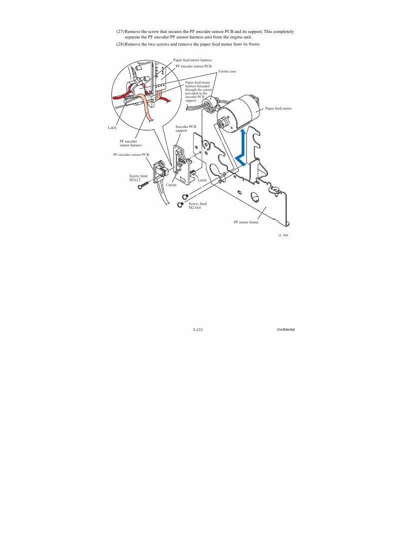
8/15/2019 Brother MFC 6510dw Sm
http://slidepdf.com/reader/full/brother-mfc-6510dw-sm 258/392
3-133 Confidential
(27)Remove the screw that secures the PF encoder sensor PCB and its support. This completelyseparate the PF encoder/PF sensor harness unit from the engine unit.
(28)Remove the two screws and remove the paper feed motor from its frame.
PF motor frame
(3_104)
Paper feed motor
Ferrite core
Encoder PCBsupport
Screw, bindM2x12
Screw, bindM2.6x4
Paper feed motorharness threadedthrough the cutout provided in theencoder PCBsupport
Paper feed motor harness
PF encoder sensor PCB
PF encoder sensor PCB
PF encodersensor harness
Latch
CutoutLatch
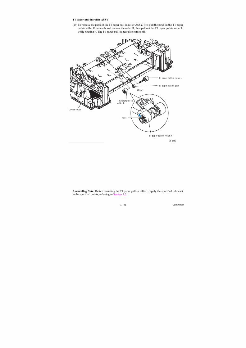
8/15/2019 Brother MFC 6510dw Sm
http://slidepdf.com/reader/full/brother-mfc-6510dw-sm 259/392
3-134 Confidential
T1 paper pull-in roller ASSY
(29)To remove the parts of the T1 paper pull-in roller ASSY, first pull the pawl on the T1 paper pull-in roller R outwards and remove the roller R, then pull out the T1 paper pull-in roller Lwhile rotating it. The T1 paper pull-in gear also comes off.
Assembling Note: Before mounting the T1 paper pull-in roller L, apply the specified lubricant
to the specified points, referring to Section 3.5.
(3_105)
Lower cover
T1 paper pull-inroller R
Pawl
T1 paper pull-in roller R
(Rear)
T1 paper pull-in gear
T1 paper pull-in roller L
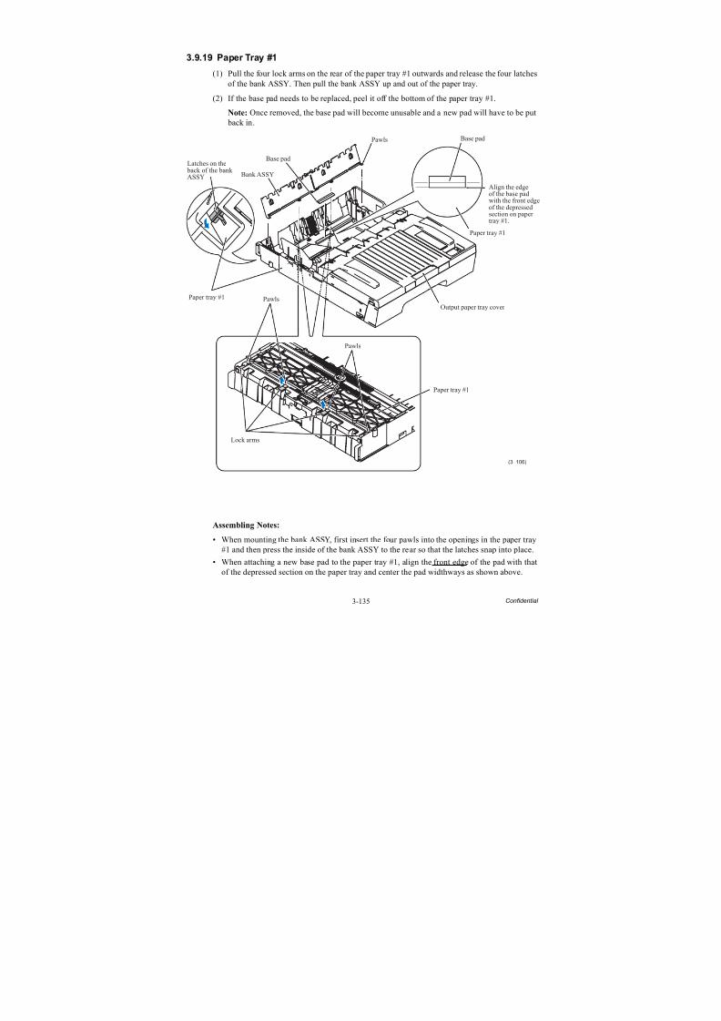
8/15/2019 Brother MFC 6510dw Sm
http://slidepdf.com/reader/full/brother-mfc-6510dw-sm 260/392
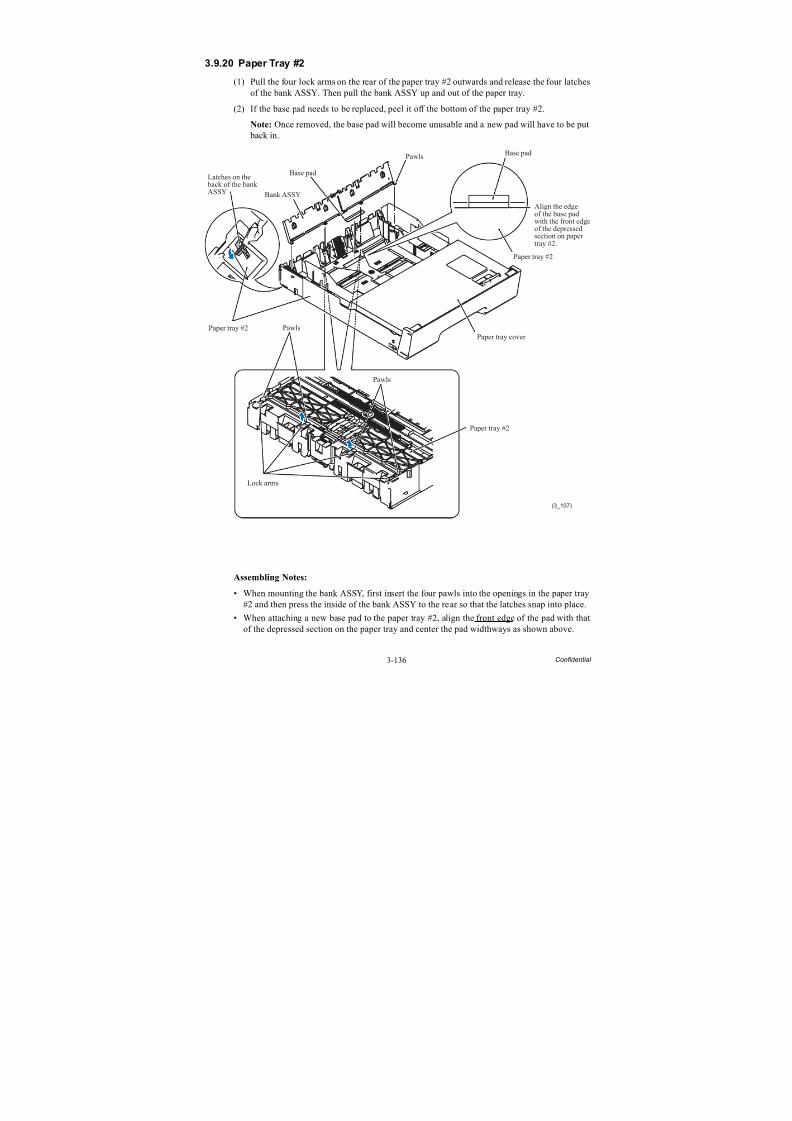
8/15/2019 Brother MFC 6510dw Sm
http://slidepdf.com/reader/full/brother-mfc-6510dw-sm 261/392
8/15/2019 Brother MFC 6510dw Sm
http://slidepdf.com/reader/full/brother-mfc-6510dw-sm 262/392
4-1 Confidential
CHAPTER 4 ADJUSTMENTS AND UPDATING OF SETTINGS,
REQUIRED AFTER PARTS REPLACEMENT
This chapter details adjustments and updating of settings, which are required if the head/carriage unit,
main PCB and some other parts have been replaced.
4.1 IF YOU REPLACE THE HEAD/CARRIAGE UNIT OR ENGINE UNIT
<Operations>
[ 1 ] Update the head property data stored in the EEPROM on the main PCB*
[ 2 ] Clean the new head/carriage unit (Function code 76)
[ 3 ] Print out a nozzle test pattern (Function code 09)[ 4 ] Adjust the inclination of the head/carriage unit
[ 5 ] Update the paper feeding correction value (Function code 58)
[ 6 ] Adjust the height of the platen
[ 7 ] Align vertical print lines in monochrome (Function code 65)
[ 8 ] Adjust margins in borderless printing (Function code 66)
[ 9 ] Create head calibration data and write it into flash ROM (Function code 02)
[ 10 ] Check duplex printing
[ 11 ] Print out a total quality check pattern[ 12 ] Switch back to standby
[ 13 ] Replace the ink cartridges with the protective part
[ 14 ] Obtain machine information at the user site (Instruction to the end user)
<Requirements>
(1) USB cable (one piece)
(2) PC (Windows® XP/2000 or later)
(3) ID/head property configuration utility (BrUsbSn.exe)(4) Download utility (FILEDG32.EXE)
(5) Maintenance driver (MaintenanceDriver.zip), if not installed
(6) Data files of print patterns
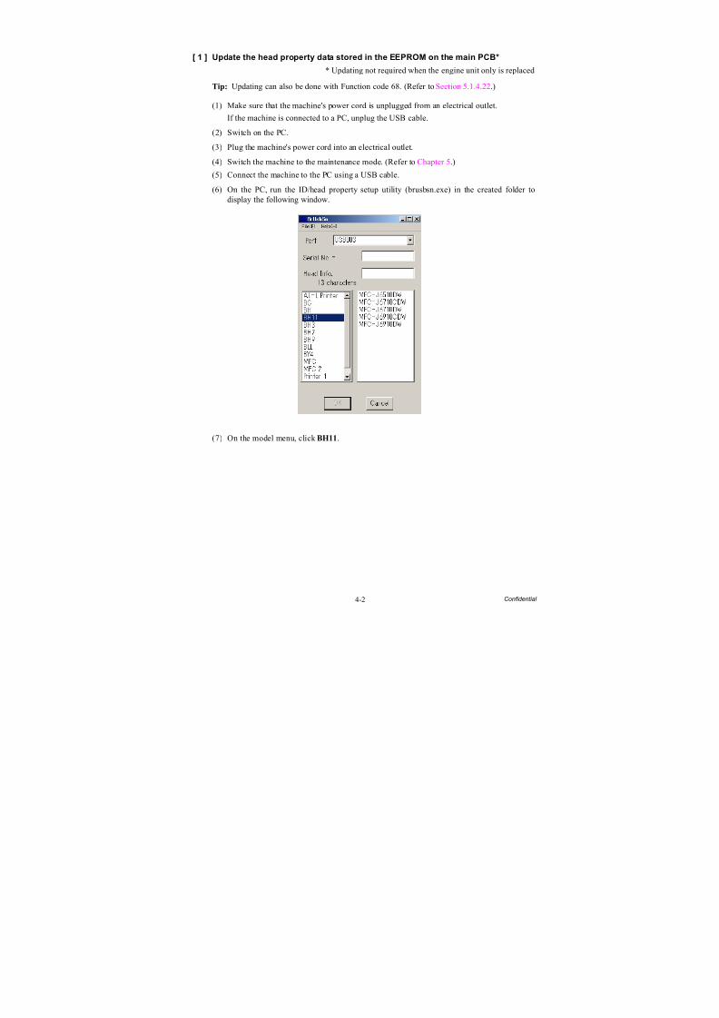
8/15/2019 Brother MFC 6510dw Sm
http://slidepdf.com/reader/full/brother-mfc-6510dw-sm 263/392
4-2 Confidential
[ 1 ] Update the head property data stored in the EEPROM on the main PCB*
* Updating not required when the engine unit only is replaced
Tip: Updating can also be done with Function code 68. (Refer to Section 5.1.4.22.)
(1) Make sure that the machine's power cord is unplugged from an electrical outlet.
If the machine is connected to a PC, unplug the USB cable.
(2) Switch on the PC.
(3) Plug the machine's power cord into an electrical outlet.
(4) Switch the machine to the maintenance mode. (Refer to Chapter 5.)
(5) Connect the machine to the PC using a USB cable.
(6) On the PC, run the ID/head property setup utility (brusbsn.exe) in the created folder todisplay the following window.
(7) On the model menu, click BH11.
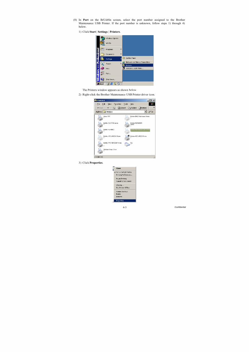
8/15/2019 Brother MFC 6510dw Sm
http://slidepdf.com/reader/full/brother-mfc-6510dw-sm 264/392
4-3 Confidential
(8) In Port on the BrUsbSn screen, select the port number assigned to the Brother Maintenance USB Printer. If the port number is unknown, follow steps 1) through 4) below.
1) Click Start | Settings | Printers.
The Printers window appears as shown below.
2) Right-click the Brother Maintenance USB Printer driver icon.
3) Click Properties.
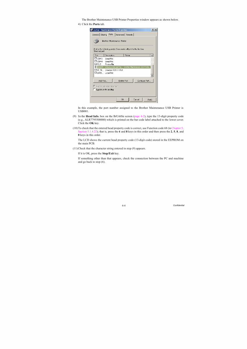
8/15/2019 Brother MFC 6510dw Sm
http://slidepdf.com/reader/full/brother-mfc-6510dw-sm 265/392
4-4 Confidential
The Brother Maintenance USB Printer Properties window appears as shown below.
4) Click the Ports tab.
In this example, the port number assigned to the Brother Maintenance USB Printer isUSB001.
(9) In the Head Info. box on the BrUsbSn screen ( page 4-2), type the 13-digit property code(e.g., ALR7795500000) which is printed on the bar code label attached to the lower cover.Click the OK key.
(10)To check that the entered head property code is correct, use Function code 68 (in Chapter 5,Section 5.1.4.22); that is, press the 6 and 8 keys in this order and then press the 2, 5, 8, and0 keys in this order.
The LCD shows the current head property code (13-digit code) stored in the EEPROM onthe main PCB.
(11)Check that the character string entered in step (9) appears.
If it is OK, press the Stop/Exit key.
If something other than that appears, check the connection between the PC and machineand go back to step (6).

8/15/2019 Brother MFC 6510dw Sm
http://slidepdf.com/reader/full/brother-mfc-6510dw-sm 266/392
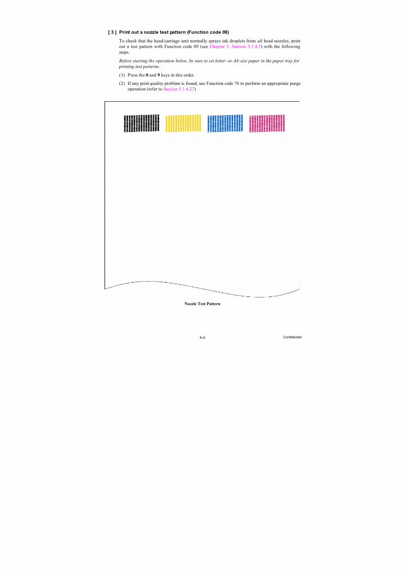
8/15/2019 Brother MFC 6510dw Sm
http://slidepdf.com/reader/full/brother-mfc-6510dw-sm 267/392
4-6 Confidential
[ 3 ] Print out a nozzle test pattern (Function code 09)
To check that the head/carriage unit normally sprays ink droplets from all head nozzles, printout a test pattern with Function code 09 (see Chapter 5, Section 5.1.4.5) with the followingsteps.
Before starting the operation below, be sure to set letter- or A4-size paper in the paper tray for
printing test patterns.
(1) Press the 0 and 9 keys in this order.
(2) If any print quality problem is found, use Function code 76 to perform an appropriate purgeoperation (refer to Section 5.1.4.27).
Nozzle Test Pattern
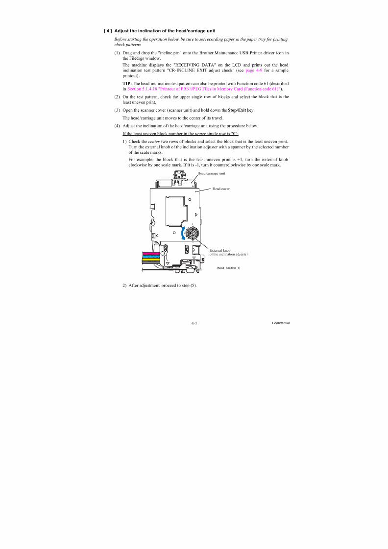
8/15/2019 Brother MFC 6510dw Sm
http://slidepdf.com/reader/full/brother-mfc-6510dw-sm 268/392
4-7 Confidential
[ 4 ] Adjust the inclination of the head/carriage unit
Before starting the operation below, be sure to set recording paper in the paper tray for printing
check patterns.
(1) Drag and drop the "incline.prn" onto the Brother Maintenance USB Printer driver icon inthe Filedrgs window.
The machine displays the "RECEIVING DATA" on the LCD and prints out the headinclination test pattern "CR-INCLINE EXIT adjust check" (see page 4-9 for a sample printout).
TIP: The head inclination test pattern can also be printed with Function code 61 (describedin Section 5.1.4.18 "Printout of PRN/JPEG Files in Memory Card (Function code 61)").
(2) On the test pattern, check the upper single row of blocks and select the block that is theleast uneven print.
(3) Open the scanner cover (scanner unit) and hold down the Stop/Exit key.
The head/carriage unit moves to the center of its travel.
(4) Adjust the inclination of the head/carriage unit using the procedure below.
If the least uneven block number in the upper single row is "0":
1) Check the center two rows of blocks and select the block that is the least uneven print.Turn the external knob of the inclination adjuster with a spanner by the selected number of the scale marks.
For example, the block that is the least uneven print is +1, turn the external knobclockwise by one scale mark. If it is -1, turn it counterclockwise by one scale mark.
2) After adjustment, proceed to step (5).
(head_position_1)
Head/carriage unit
Head cover
External knobof the inclination adjuster
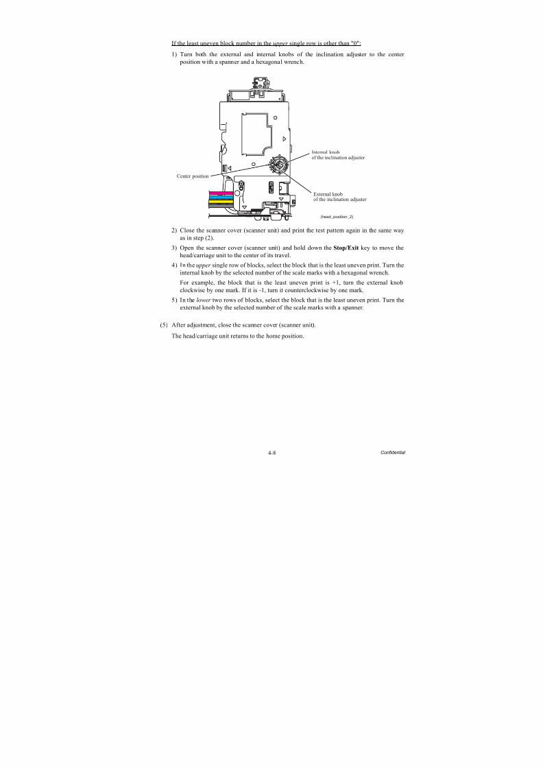
8/15/2019 Brother MFC 6510dw Sm
http://slidepdf.com/reader/full/brother-mfc-6510dw-sm 269/392
4-8 Confidential
If the least uneven block number in the upper single row is other than "0":
1) Turn both the external and internal knobs of the inclination adjuster to the center position with a spanner and a hexagonal wrench.
2) Close the scanner cover (scanner unit) and print the test pattern again in the same wayas in step (2).
3) Open the scanner cover (scanner unit) and hold down the Stop/Exit key to move thehead/carriage unit to the center of its travel.
4) In the upper single row of blocks, select the block that is the least uneven print. Turn theinternal knob by the selected number of the scale marks with a hexagonal wrench.
For example, the block that is the least uneven print is +1, turn the external knobclockwise by one mark. If it is -1, turn it counterclockwise by one mark.
5) In the lower two rows of blocks, select the block that is the least uneven print. Turn theexternal knob by the selected number of the scale marks with a spanner.
(5) After adjustment, close the scanner cover (scanner unit).
The head/carriage unit returns to the home position.
(head_position_2)
External knobof the inclination adjuster
Internal knobof the inclination adjuster
Center position
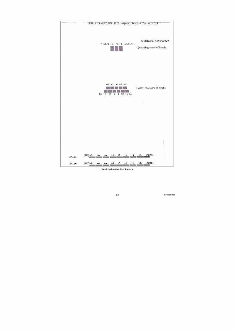
8/15/2019 Brother MFC 6510dw Sm
http://slidepdf.com/reader/full/brother-mfc-6510dw-sm 270/392
4-9 Confidential
Head Inclination Test Pattern
Upper single row of blocks
Center two rows of blocks
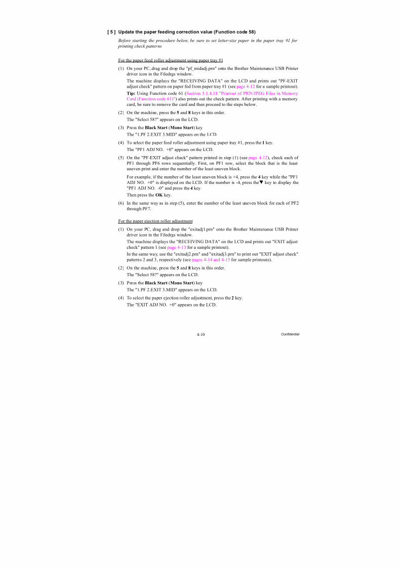
8/15/2019 Brother MFC 6510dw Sm
http://slidepdf.com/reader/full/brother-mfc-6510dw-sm 271/392
4-10 Confidential
[ 5 ] Update the paper feeding correction value (Function code 58)
Before starting the procedure below, be sure to set letter-size paper in the paper tray #1 for
printing check patterns
For the paper feed roller adjustment using paper tray #1
(1) On your PC, drag and drop the "pf_midadj.prn" onto the Brother Maintenance USB Printer driver icon in the Filedrgs window.
The machine displays the "RECEIVING DATA" on the LCD and prints out "PF-EXITadjust check" pattern on paper fed from paper tray #1 (see page 4-12 for a sample printout).
Tip: Using Function code 61 (Section 5.1.4.18 "Printout of PRN/JPEG Files in MemoryCard (Function code 61)") also prints out the check pattern. After printing with a memorycard, be sure to remove the card and then proceed to the steps below.
(2) On the machine, press the 5 and 8 keys in this order.
The "Select 58?" appears on the LCD.
(3) Press the Black Start (Mono Start) key.The "1.PF 2.EXIT 3.MID" appears on the LCD.
(4) To select the paper feed roller adjustment using paper tray #1, press the 1 key.
The "PF1 ADJ NO. +0" appears on the LCD.
(5) On the "PF-EXIT adjust check" pattern printed in step (1) (see page 4-12), check each of PF1 through PF6 rows sequentially. First, on PF1 row, select the block that is the leastuneven print and enter the number of the least uneven block.
For example, if the number of the least uneven block is +4, press the 4 key while the "PF1ADJ NO. +0" is displayed on the LCD. If the number is -4, press the key to display the"PF1 ADJ NO. -0" and press the 4 key.
Then press the OK key.
(6) In the same way as in step (5), enter the number of the least uneven block for each of PF2through PF7.
For the paper ejection roller adjustment
(1) On your PC, drag and drop the "exitadj1.prn" onto the Brother Maintenance USB Printer driver icon in the Filedrgs window.
The machine displays the "RECEIVING DATA" on the LCD and prints out "EXIT adjustcheck" pattern 1 (see page 4-13 for a sample printout).
In the same way, use the "exitadj2.prn" and "exitadj3.prn" to print out "EXIT adjust check" patterns 2 and 3, respectively (see pages 4-14 and 4-15 for sample printouts).
(2) On the machine, press the 5 and 8 keys in this order.
The "Select 58?" appears on the LCD.
(3) Press the Black Start (Mono Start) key.
The "1.PF 2.EXIT 3.MID" appears on the LCD.
(4) To select the paper ejection roller adjustment, press the 2 key.
The "EXIT ADJ NO. +0" appears on the LCD.
8/15/2019 Brother MFC 6510dw Sm
http://slidepdf.com/reader/full/brother-mfc-6510dw-sm 272/392
4-11 Confidential
(5) On the "EXIT adjust check" patterns 1 to 3 (see pages 4-13 through 4-15), check EXIT1through EXIT6 rows.
First, on the EXIT1 row, select the block that is the least uneven print and enter the number of the least uneven block. For the entry method, refer to the paper feed roller adjustment procedure, step (5).
Then press the OK key.(6) In the same way as in step (5), enter the number of the least uneven block for each of EXT2
through EXIT6.
For the intermediate roller adjustment
(1) On the machine, press the 5 and 8 keys in this order.
The "Select 58?" appears on the LCD.
(2) Press the Black Start (Mono Start) key.
The "1.PF 2.EXIT 3.MID" appears on the LCD.
(3) To select the intermediate roller adjustment, press the 3 key.The "MID ADJ NO. +0" appears on the LCD.
(4) On the "PF-EXIT adjust check" pattern (see page 4-12), check the MID row. Select the block that is the least uneven print and enter the number of the least uneven block. For theentry method, refer to the paper feed roller adjustment procedure, step (5).
For adjustment for horizontal streaks
(1) On your PC, drag and drop the "LF300adj.prn" onto the Brother Maintenance USB Printer driver icon in the Filedrgs window.
The machine displays the "RECEIVING DATA" on the LCD and prints out "KEISEN2 &
LF300 & EXIT ADJUST PATTERN" (see page 4-16 for a sample printout).
Tip: Using Function code 61 (Section 5.1.4.18 "Printout of PRN/JPEG Files in MemoryCard (Function code 61)") also prints out the check pattern. After printing with a memorycard, be sure to remove the card and then proceed to the steps below.
(2) On the machine, press the 5 and 8 keys in this order.
The "Select 58?" appears on the LCD.
(3) Press the Black Start (Mono Start) key.
The "1.PF 2.EXIT 3.MID" appears on the LCD.
(4) Press the key several times to display the "1.LF300" on the LCD.
(5) Press the 1 key to display the "LF300 ADJ No. +0."
(6) Check the LF300 ADJUST pattern (see page 4-16), select the block that has the least whiteand black streaks, and enter the number of that block. For the entry method, refer to the paper feed roller adjustment procedure, step (5).
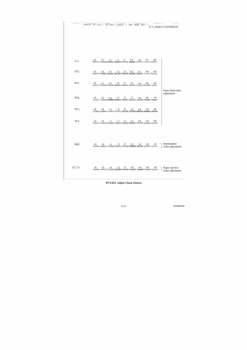
8/15/2019 Brother MFC 6510dw Sm
http://slidepdf.com/reader/full/brother-mfc-6510dw-sm 273/392
4-12 Confidential
PF-EXIT Adjust Check Pattern
Paper feed rolleradjustment
Intermediateroller adjustment
Paper ejectionroller adjustment
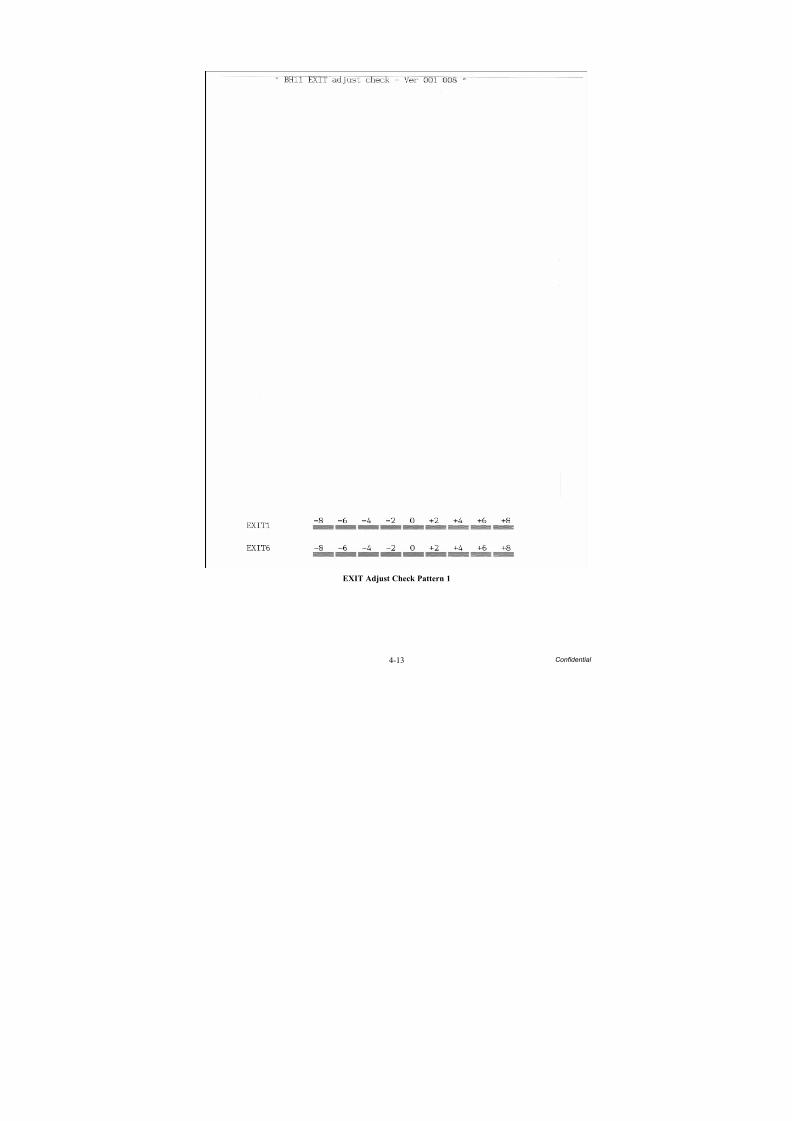
8/15/2019 Brother MFC 6510dw Sm
http://slidepdf.com/reader/full/brother-mfc-6510dw-sm 274/392
4-13 Confidential
EXIT Adjust Check Pattern 1

8/15/2019 Brother MFC 6510dw Sm
http://slidepdf.com/reader/full/brother-mfc-6510dw-sm 275/392
4-14 Confidential
EXIT Adjust Check Pattern 2

8/15/2019 Brother MFC 6510dw Sm
http://slidepdf.com/reader/full/brother-mfc-6510dw-sm 276/392
4-15 Confidential
EXIT Adjust Check Pattern 3
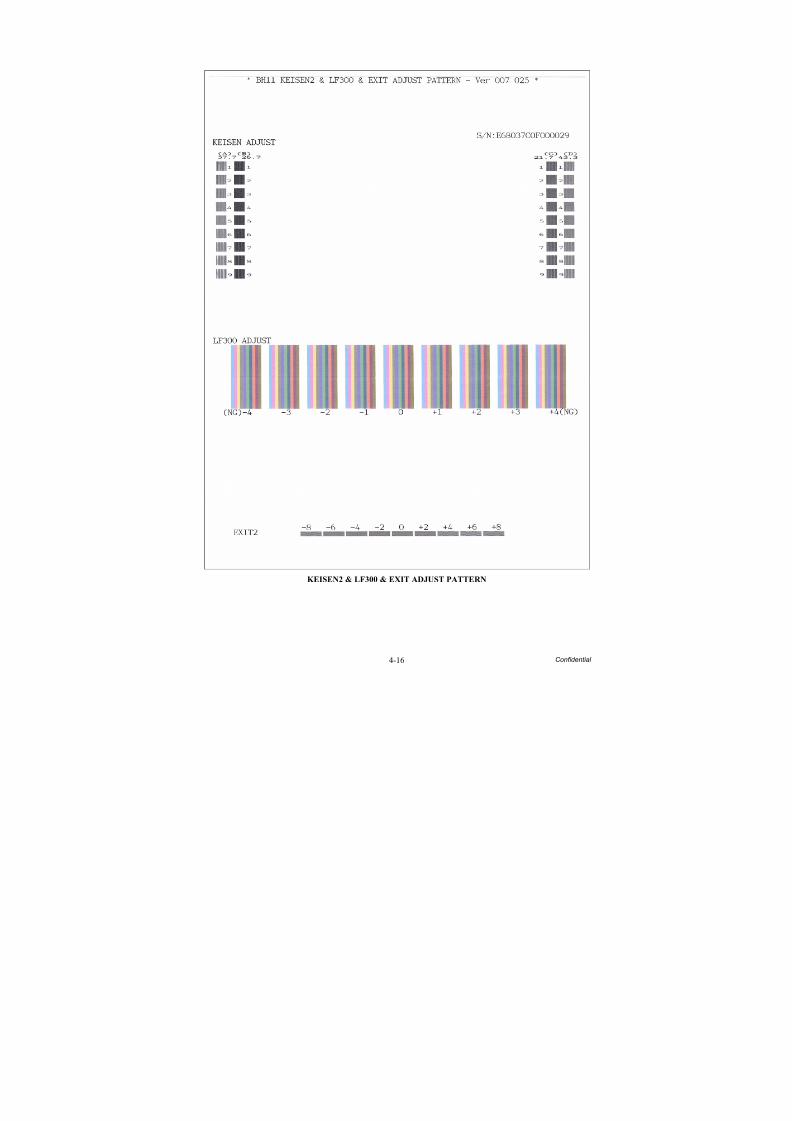
8/15/2019 Brother MFC 6510dw Sm
http://slidepdf.com/reader/full/brother-mfc-6510dw-sm 277/392
4-16 Confidential
KEISEN2 & LF300 & EXIT ADJUST PATTERN
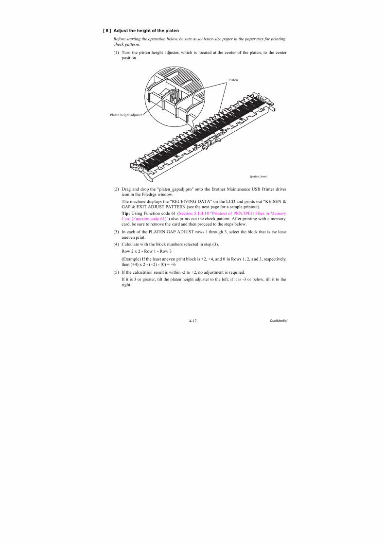
8/15/2019 Brother MFC 6510dw Sm
http://slidepdf.com/reader/full/brother-mfc-6510dw-sm 278/392
4-17 Confidential
[ 6 ] Adjust the height of the platen
Before starting the operation below, be sure to set letter-size paper in the paper tray for printing
check patterns.
(1) Turn the platen height adjuster, which is located at the center of the platen, to the center position.
(2) Drag and drop the "platen_gapadj.prn" onto the Brother Maintenance USB Printer driver icon in the Filedrgs window.
The machine displays the "RECEIVING DATA" on the LCD and prints out "KEISEN &GAP & EXIT ADJUST PATTERN (see the next page for a sample printout).
Tip: Using Function code 61 (Section 5.1.4.18 "Printout of PRN/JPEG Files in MemoryCard (Function code 61)") also prints out the check pattern. After printing with a memorycard, be sure to remove the card and then proceed to the steps below.
(3) In each of the PLATEN GAP ADJUST rows 1 through 3, select the block that is the leastuneven print.
(4) Calculate with the block numbers selected in step (3).Row 2 x 2 - Row 1 - Row 3
(Example) If the least uneven print block is +2, +4, and 0 in Rows 1, 2, and 3, respectively,then (+4) x 2 - (+2) - (0) = +6
(5) If the calculation result is within -2 to +2, no adjustment is required.
If it is 3 or greater, tilt the platen height adjuster to the left; if it is -3 or below, tilt it to theright.
(platen_lever)
Platen
Platen height adjuster
8/15/2019 Brother MFC 6510dw Sm
http://slidepdf.com/reader/full/brother-mfc-6510dw-sm 279/392
4-18 Confidential
KEISEN & GAP EXIT ADJUST PATTERN
Line 1
Line 2
Line 3
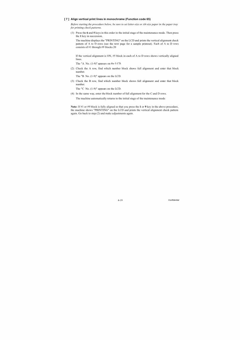
8/15/2019 Brother MFC 6510dw Sm
http://slidepdf.com/reader/full/brother-mfc-6510dw-sm 280/392
4-19 Confidential
[ 7 ] Align vertical print lines in monochrome (Function code 65)
Before starting the procedure below, be sure to set letter-size or A4-size paper in the paper tray
for printing check patterns.
(1) Press the 6 and 5 keys in this order in the initial stage of the maintenance mode. Then pressthe 1 key in succession.
The machine displays the "PRINTING" on the LCD and prints the vertical alignment check pattern of A to D rows (see the next page for a sample printout). Each of A to D rowsconsists of #1 through #9 blocks.20
If the vertical alignment is ON, #5 block in each of A to D rows shows vertically alignedlines.
The "A No. (1-9)" appears on the LCD.
(2) Check the A row, find which number block shows full alignment and enter that block number.
The "B No. (1-9)" appears on the LCD.(3) Check the B row, find which number block shows full alignment and enter that block
number.
The "C No. (1-9)" appears on the LCD.
(4) In the same way, enter the block number of full alignment for the C and D rows.
The machine automatically returns to the initial stage of the maintenance mode.
Note: If #1 or #9 block is fully aligned so that you press the 1 or 9 key in the above procedure,the machine shows "PRINTING" on the LCD and prints the vertical alignment check pattern
again. Go back to step (2) and make adjustments again.
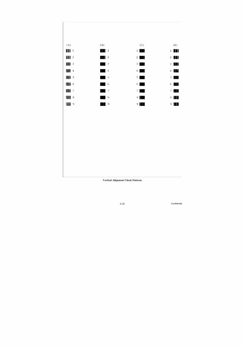
8/15/2019 Brother MFC 6510dw Sm
http://slidepdf.com/reader/full/brother-mfc-6510dw-sm 281/392
4-20 Confidential
Vertical Alignment Check Patterns
8/15/2019 Brother MFC 6510dw Sm
http://slidepdf.com/reader/full/brother-mfc-6510dw-sm 282/392
4-21 Confidential
[ 8 ] Adjust margins in borderless printing (Function code 66)
Before starting the procedure below, be sure to set letter-size paper in the paper tray for
printing check patterns.
Left and right margin adjustment
(1) On your PC, drag and drop the "mediaadj.prn" onto the Brother Maintenance USB Printer driver icon in the Filedrgs window.
The machine displays the "RECEIVING DATA" on the LCD and prints out the "MEDIACHECK" pattern (see page 4-23 for a sample printout). This margin check pattern is usedto check the left, right and bottom margins.
Tip: Using Function code 61 (Section 5.1.4.18 "Printout of PRN/JPEG Files in MemoryCard (Function code 61)") also prints out the check pattern. After printing with a memorycard, be sure to remove the card and then proceed to the steps below.
(2) Measure the left and right margins on the printed pattern.
The upper row is printed in 600 dpi, and the lower row, in 1200 dpi.
(Example) 600 dpi Left: 0.8 mm, Right: 1.1 mm1200 dpi Left: 0.9 mm, Right: 1.2 mm
If both of the left and right margins are within the range from 0.9 to 1.1 mm, no adjustmentis required. If not, go to step (3).
(3) If either one of the left and right margins is out of the specified range, press the 6 key twiceon the machine.
The "Select 66?" appears on the LCD.
(4) Press the Black Start (Mono Start) key.
The "MEDIA SENSOR ADJ" appears on the LCD.
(5) Press the * key to display "LEFT1 :10."(6) To adjust the left margin in 600 dpi, enter the measured value (in units of 0.1 mm)
multiplied by 10.
In this example, the left margin measured in step (2) is 0.8 mm, so press the 0, 8, and OK
keys.
NOTE: In models having no OK key on the control panel, press the PHOTO CAPTURE
key.
The "RIGHT1: 10" appears on the LCD.
(7) To adjust the right margin in 600 dpi, enter the measured value (in units of 0.1 mm)multiplied by 10.
In this example, the right margin measured in step (2) is 1.1 mm, so press the 1, 1, and OK
keys.
The "LEFT2: 10" appears on the LCD.
(8) To adjust the left margin in 1200 dpi, enter the measured value (in units of 0.1 mm)multiplied by 10.
In this example, the right margin measured in step (2) is 0.9 mm, so press the 0, 9, and OK
keys.
The "RIGHT2: 10" appears on the LCD.
8/15/2019 Brother MFC 6510dw Sm
http://slidepdf.com/reader/full/brother-mfc-6510dw-sm 283/392
4-22 Confidential
(9) To adjust the right margin in 1200 dpi, enter the measured value (in units of 0.1 mm)multiplied by 10.
In this example, the right margin measured in step (2) is 1.2 mm, so press the 1, 2, and OK
keys.
Upon completion of the entry, the machine automatically returns to the initial stage of the
maintenance mode.(10)Go back to step (1) and print out the margin check pattern again.
(11)Measure the left and right margins on the printed pattern.
If both the left and right margins are within the range from 0.9 to 1.1 mm, the adjustment iscompleted.
Bottom margin adjustment
(1) Measure the bottom margin on the "MEDIA CHECK" pattern printed in the left and rightmargin adjustment procedure, step (1) above.
(Example) Bottom margin: 3.2 mmIf it is within the range from 2.9 to 3.1 mm, no adjustment is required. If not, go to step (2).
(2) If the bottom margin is out of the specified range, press the 6 key twice on the machine.
(3) Press the Black Start (Mono Start) key.
The "MEDIA SENSOR ADJ" appears on the LCD.
(4) Press the # key to display "BOTTOM :30."
(5) To adjust the bottom margin, enter the measured value (in units of 0.1 mm) multiplied by10.
In this example, the bottom margin measured in step (1) is 3.2 mm, so press the 3, 2, and
OK keys.Upon completion of the entry, the machine automatically returns to the initial stage of themaintenance mode.
(6) Go back to step (1) of the left and right margin adjustment and print out the margin check pattern again.
(7) Measure the bottom margin on the printed pattern.
If it is within the range from 2.9 to 3.1 mm, the adjustment is completed.
Note: To reset the correction values newly entered in the above procedure, press the 6, 6, Start,8, 9, 5 and 4 keys in this order in the initial stage of the maintenance mode. The machine shows
"PARAMETER INIT" on the LCD and returns to the initial stage of the maintenance mode.

8/15/2019 Brother MFC 6510dw Sm
http://slidepdf.com/reader/full/brother-mfc-6510dw-sm 284/392
4-23 Confidential
Left, Right and Bottom Margin Check Pattern
8/15/2019 Brother MFC 6510dw Sm
http://slidepdf.com/reader/full/brother-mfc-6510dw-sm 285/392
4-24 Confidential
[ 9 ] Create head calibration data and write it into flash ROM
(Function code 02)
Notes • Before proceeding to the procedure given below, use Function code 55 (described inSection 5.1.4.15 "Acquisition of White Level Data and CIS Scanner Area Setting(Function code 55)"). If not, this function may fail to create head calibration data
correctly.• Make sure that all of the scanner cover (scanner unit), document cover and ADF cover
are closed.
• For higher precision of uneven printing correction, use the recording paper specified below to print the "pattern for creating head calibration data."
US: Xerox 4200DP 20 lb., Brother BP60PLEU, AP and others: Xerox Business 80 g/m2, Brother BP60PA
(1) Drag and drop the "head_calib.prn" icon onto the Brother Maintenance USB Printer driver icon in the Filedrgs window.
The machine displays the "RECEIVING DATA" on the LCD and prints out "Print pattern
for creating head calibration data" (see page 4-26 for a sample printout).Tip: Using Function code 61 (Section 5.1.4.18 "Printout of PRN/JPEG Files in MemoryCard (Function code 61)") also prints out the print pattern. After printing with a memorycard, be sure to remove the card and then proceed to the steps below.
Note: Make sure that the USB cable is disconnected.
(2) Set the print pattern on the scanner glass of the document cover.
(3) Press the 0 and 2 keys in this order in the initial stage of the maintenance mode.
The "MAINTENANCE 02" and "Set Sheet on FB?" appear on the LCD in this order.
Note: Pressing the Stop/Exit key immediately returns the machine to the initial stage of the
maintenance mode without creating head calibration data.
(4) Press the Black Start (Mono Start) key.
The machine displays the "Scanning" on the LCD and starts scanning the "Print pattern for creating head calibration data" placed on the scanner glass.
Upon completion of scanning, the machine displays the "Write Head Calib" on the LCD,creates the head calibration data, and writes it into the flash ROM on the main PCB.
Upon completion of writing, the "Complete" appears. Press the Stop/Exit key to return tothe initial stage of the maintenance mode.
Note: If an error occurs, the machine beeps and displays "Error No **" on the LCD. Press
the Stop/Exit key to return to the initial stage of the maintenance mode and then recover the machine from the error state, following the table given on the next page. Then go back to step (2).

8/15/2019 Brother MFC 6510dw Sm
http://slidepdf.com/reader/full/brother-mfc-6510dw-sm 286/392
4-25 Confidential
Error code The following error has occurred. Do the following:
01 Failed to detect the external frame. • Clean the scanner glass.• Reposition a document along the
document guides on the document
cover.• Go back to step (1) and print out "Print
pattern for creating head calibrationdata" again.
02 Internal image inclined.
03 Failed to detect position.
04 Failed to write head calibration data. • Clean the scanner glass.
• Reposition a document along thedocument guides on the documentcover.
• Restart the machine and perform thefunction again.
• Replace the main PCB.
05 The uneven printing correctionfunction for upper and lower ends ofthe nozzle is disabled with Functioncode 88.
• Use Function code 88 (in Section5.1.4.33 "Assurance Mode SwitchSetting (Function code 88) (User-accessible)") to set selector 1 on AMS05to "0."
06 Cannot get memory space. • Delete stored data including fax data.• Stop any other function if being used.• Replace the main PCB.
07 The scanner cover (scanner unit) isopen.
• Close the scanner cover.• Reconnect the panel-main harness.
• Reposition the scanner cover sensoractuator.
• Replace the rubber keypad(s).• Replace the control panel PCB.
• Replace the scanner cover.• Replace the main PCB.
08 The ADF cover is open. • Close the ADF cover.• Reconnect the ADF cover switch
harness.
• Replace the ADF cover.• Replace the ADF harness unit.• Replace the main PCB.
09 Other scanning errors • Use Function code 55 (Section 5.1.4.15"Acquisition of White Level Data andCIS Scanner Area Setting (Functioncode 55)").
10 A media is inserted and also the USBcable or LAN cable is connected.
• Disconnect the USB cable.

8/15/2019 Brother MFC 6510dw Sm
http://slidepdf.com/reader/full/brother-mfc-6510dw-sm 287/392
4-26 Confidential
Print Pattern for Creating Head Calibration Data

8/15/2019 Brother MFC 6510dw Sm
http://slidepdf.com/reader/full/brother-mfc-6510dw-sm 288/392
4-27 Confidential
[ 10 ] Check duplex printing
Note: Only when the engine unit is replaced, perform the following procedure.
Before starting the operation below, be sure to set letter-paper in paper tray #2 for printing test
patterns and remove all sheets of paper from paper tray #1.
(1) Drag and drop the "LT_Duplex.prn" onto the Brother Maintenance USB Printer driver iconin the Filedrgs window.
The machine displays the "RECEIVING DATA" on the LCD and prints out duplex printcheck patterns 1 and 2 (see pages 4-28 and 4-29 for sample printouts).
(2) Check the first and second sides of the printout to make sure that there is a margin betweenthe paper edge and each of the four black blocks.
If there is a margin, no adjustment is required. If there is no margin, reposition the engineunit. (Refer to Chapter 3, Section 3.9.17.)
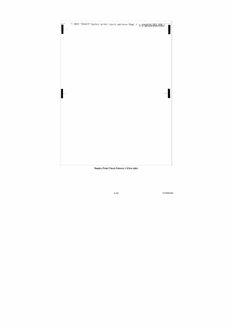
8/15/2019 Brother MFC 6510dw Sm
http://slidepdf.com/reader/full/brother-mfc-6510dw-sm 289/392
4-28 Confidential
Duplex Print Check Pattern 1 (First side)
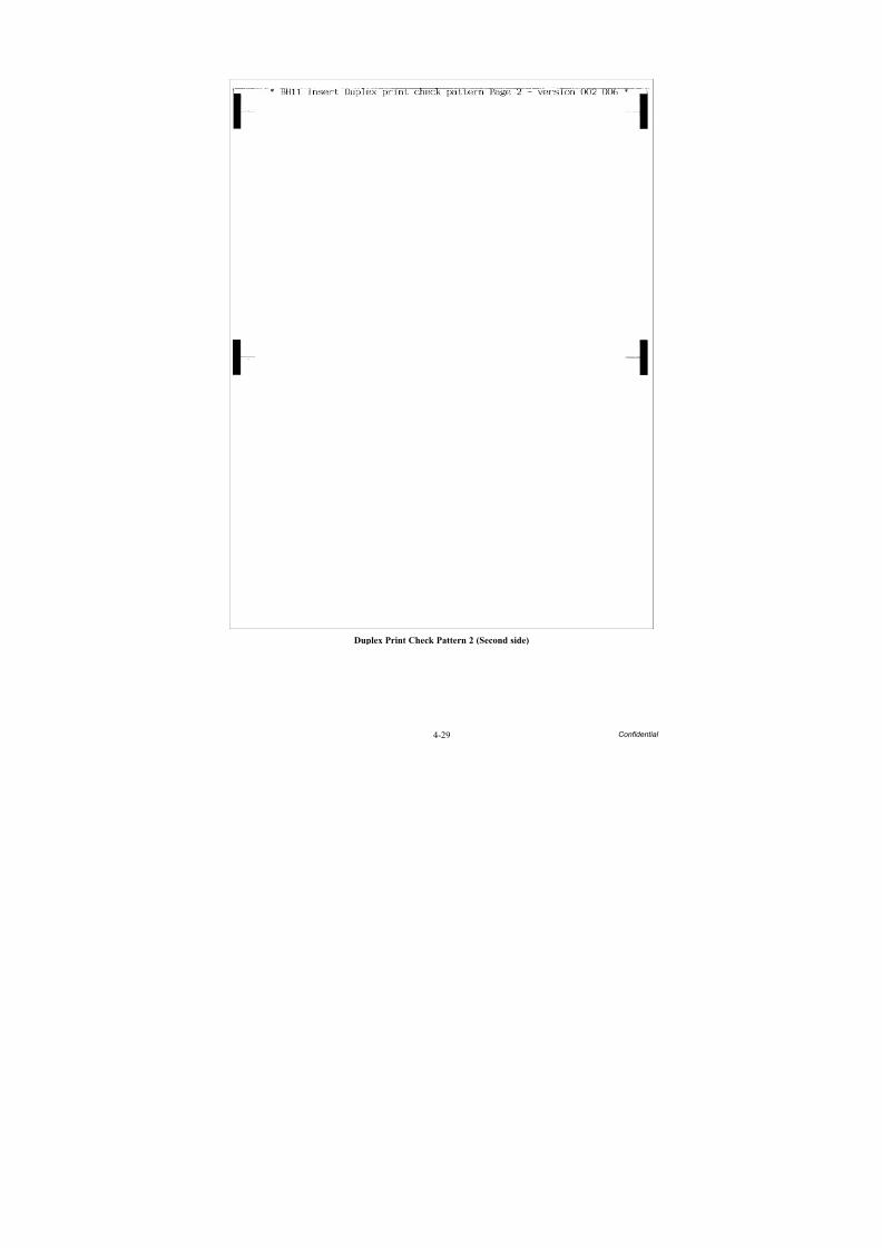
8/15/2019 Brother MFC 6510dw Sm
http://slidepdf.com/reader/full/brother-mfc-6510dw-sm 290/392
4-29 Confidential
Duplex Print Check Pattern 2 (Second side)
8/15/2019 Brother MFC 6510dw Sm
http://slidepdf.com/reader/full/brother-mfc-6510dw-sm 291/392
4-30 Confidential
[ 11 ] Print out a total quality check pattern
Before starting the operation below, be sure to set letter-size paper in the paper tray for printing
check patterns.
Tip: Using Function code 61 (Section 5.1.4.18 "Printout of PRN/JPEG Files in Memory Card(Function code 61)") also prints out the check pattern. After printing with a memory card, be
sure to remove the card and then proceed to the steps below.
(1) Drag and drop the "qualbh11.prn" onto the Brother Maintenance USB Printer driver icon inthe Filedrgs window.
The machine displays the "RECEIVING DATA" on the LCD and prints out the "TotalQuality Check Pattern" (see the next page for a sample printout).
(2) Check the printed check pattern. If any problem is found, go back to the related item (anyof [ 4 ] through [ 8 ] above) and make adjustments again.
(3) Repeat steps (1) and (2) until no problem is found.
A:Margin adjustment for
borderless printing (600 dpi)
Check that there is no left or right margin in 600 dpi.
If any margin is found, go back to [ 8 ].B: Platen height adjustment Check that the OK block shows the least uneven print.
If not, go back to [ 6 ].
C: Adjustment of vertical printlines
Check that any of the blocks except NG blocks shows the leastuneven print.If any NG block shows the least uneven print, go back to [ 7 ].
D: Inclination adjustment of thehead/carriage unit
Check that any of the blocks except NG blocks shows the lightestcheckered pattern.If any NG block shows the lightest checkered pattern, go back to[ 4 ].
E: Paper feed roller adjustment Check that any of the +2 to -2 blocks shows the least uneven print.If any other block shows the least uneven print, go back to [ 5 ].
F: Intermediate roller adjustment Check that any of the +2 to -2 blocks shows the lightest checkered pattern.If any other block shows the lightest checkered pattern, go back to[ 5 ].
G:Margin adjustment for borderless printing (1200 dpi)
Check that there is no left or right margin in 1200 dpi.If any margin is found, go back to [ 8 ].
H: Paper ejection rolleradjustment
Check that any of the +2 to -2 blocks shows the lightest checkered pattern.If any other block shows the lightest checkered pattern, go back to[ 5 ].
8/15/2019 Brother MFC 6510dw Sm
http://slidepdf.com/reader/full/brother-mfc-6510dw-sm 292/392
4-31 Confidential
Total Quality Check Pattern
A: Margin adjustment for borderless printing (600 dpi)B: Platen height adjustmentC: Adjustment of vertical print linesD: Inclination adjustment of the head/carriage unitE: Paper feed roller adjustmentF: Intermediate roller adjustmentG: Margin adjustment for borderless printing (1200 dpi)H: Paper ejection roller adjustment
8/15/2019 Brother MFC 6510dw Sm
http://slidepdf.com/reader/full/brother-mfc-6510dw-sm 293/392
4-32 Confidential
[ 12 ] Switch back to standby
After completion of adjustments, disconnect the USB cable and press the 9 key twice to returnto the standby state.
Note: Be sure to disconnect the USB cable first. Returning to standby without disconnecting theUSB cable runs "Found New Hardware Wizard" that starts USB driver installation.
[ 13 ] Replace the ink cartridges with the protective part
Remove all four ink cartridges and set the protective part instead. Check that the right-handlatch fits in the hole provided in the ink refill ASSY.
[ 14 ] Obtain machine information at the user site (Instruction to the end user)
When the user receives the repaired machine, he/she needs to obtain the head calibration datainto his/her PC at the user site. The service personnel should contact the user to instruct him/her to perform the following procedure.
Windows
(1) On the user computer, click Start | Settings | Printers to display the Printers window.
(2) Right-click the Brother Printer driver icon to display the pull-down menu.
(3) Click Properties | Print Settings | Advanced | Other print options | Retrieve Printer’s
Color Data.
(4) Check that the Retrieve Printer’s Color Data check box is selected.
(5) Click Retrieve Printer’s Color Data.
(6) Wait for the dialog to appear and click OK .
Macintosh
(1) On the user Mac, display the printer list and select the repaired machine.
(2) Select Open Print Queue | Printer Setup | Utility | Open Printer Utility.
(3) From the menu bar, select Control | Color Calibration.
(4) Wait for the dialog to appear and click OK .
(Protective_part_M11)Protective part
8/15/2019 Brother MFC 6510dw Sm
http://slidepdf.com/reader/full/brother-mfc-6510dw-sm 294/392
4-33 Confidential
4.2 IF YOU REPLACE THE MAIN PCB
Note: If you replace the main PCB, it is necessary to make a backup of the machine information, user setting information, and head calibration data into an external memory before starting disassembly of the machine. After the completion of reassembling jobs, restore the backup data to the new main
PCB. For detailed procedure of the backup and restoration, refer to Chapter 5, Section 5.1.4.11"Backup of Machine Information (Function code 46) (User-accessible)" and Section 5.1.4.22"Updating of Head Property Data and Backup/Restoration of Head Calibration Data (Function code68)."
Note: For this series of machines, load programs onto the main PCB twice for basic programs andlocal programs. That is, after replacement of the main PCB, load basic programs, customize theEEPROM for the destination with Function code 74, and then load local programs.
<Operations>
[ 1 ] Load update programs/data
[ 2 ] Customize the EEPROM on the main PCB (Function code 74)[ 3 ] Initialize the EEPROM on the main PCB (Function code 01)
[ 4 ] Load local programs
[ 5 ] Restore machine information (Function code 46)
[ 6 ] Restore head calibration data (Function code 68)
[ 7 ] Check the sensor operation (Function code 32)
[ 8 ] Acquire white level data and set CIS scanner area (Function code 55)
[ 9 ] Set an ID code (change the serial number) and update the head property data
[ 10 ] Update the paper feeding correction value (Function code 58)
[ 11 ] Align vertical print lines (Function code 65)
[ 12 ] Adjust margins in borderless printing (Function code 66)
[ 13 ] Create head calibration data and write it into flash ROM (Function code 02)
[ 14 ] Print out an ADF copy chart and make a copy of that chart in ADF scanning
[ 15 ] Print out a total quality check pattern
[ 16 ] Adjust the touch panel (Function code 78) (For models with touch panel)
[ 17 ] Switch back to standby
<Requirements>
(1) USB cable (one piece)
(2) Computer (Windows® XP/2000 or later)
(3) ID/head property configuration utility (BrUsbSn.exe)
(4) Download utility (FILEDG32.EXE)
(5) Maintenance driver (MaintenanceDriver.zip)
(6) Data files of print patterns
8/15/2019 Brother MFC 6510dw Sm
http://slidepdf.com/reader/full/brother-mfc-6510dw-sm 295/392
4-34 Confidential
[ 1 ] Load update programs/data
This procedure writes firmware to the main PCB or updates it.
If the main PCB is replaced with a new one
Unplug the power cord of the machine from the electrical outlet and disconnect the USBcable that connects the machine with your PC.
(1) On the machine, follow the steps below to enter the firmware loading mode.
1) Plug the power cord into an electrical outlet with the 0 key (Scan key) held downand keep holding it down until the following appears on the LCD. While the 0 key(Scan key) is held down, the machine beeps.
2) Hold down the 1 key until the following appears on the LCD. While the 1 key is
held down, the machine beeps.
3) Hold down the 2 key until the following appears on the LCD. While the 2 key isheld down, the machine beeps.
4) Hold down the 3 key until the following appears on the LCD. While the 3 key isheld down, the machine beeps.
When the black and white pattern shown above is displayed, the machine is ready toreceive programs or data for firmware installation from the connected PC.
Note: Pressing a wrong key or no key within the specified time in steps 1) through 4)above causes an error. If it happens, unplug the power cord and go back to step 1)above.
(2) Connect the machine to your PC using a USB cable.
8/15/2019 Brother MFC 6510dw Sm
http://slidepdf.com/reader/full/brother-mfc-6510dw-sm 296/392
4-35 Confidential
(3) On your PC, run "filedg32.exe."
The Filedrgs window will appear as shown below.
(4) Drag and drop the firmware (e.g., lz0023_a.pmu) onto the Brother Maintenance USBPrinter driver icon in the Filedrgs window.
Note: To use a firmware file, extract it beforehand by double-clicking. It is a self-extracting file having the extension .exe.
After approx. 2 to 5 minutes, the loading operation is complete and the machine
automatically reboots and returns to the standby state.
(5) On the machine, display the version of the installed firmware on the LCD by pressingthe * and # keys simultaneously.
Sample version number shown on the LCD: 0A810060953:4B69(The top line shows the version number.) P0601242005:4123
B0601242005:1C8D
If the displayed version number is identical with the firmware version you installed,the loading operation has been successfully finished.
Note: If loading operation ends abnormally, turn the machine off and on. Wait for themachine to emit a long beep and automatically enter the firmware loading mode, and then
perform the loading procedure above again.
8/15/2019 Brother MFC 6510dw Sm
http://slidepdf.com/reader/full/brother-mfc-6510dw-sm 297/392
4-36 Confidential
If the main PCB loaded with programs is used (Updating existing programs)
A main PCB used for any other machine has been loaded with programs. If the currentmain PCB is replaced with such a used PCB, update existing programs using the proceduregiven below.
Note: This operation can also be done with Function code 28. (Refer to Chapter 5, Section5.1.4.9).
Unplug the power cord from the electrical outlet and make sure that the machine isconnected with your PC using a USB cable.
While holding down the 5 key, plug the power cord into an electrical outlet.
The black and white pattern appears on the LCD as shown on the previous page. Themachine is ready to receive programs or data for firmware installation from the connectedPC.
(1) On your PC, run "filedg32.exe."
The Filedrgs window appears as shown below.
(2) Drag and drop the firmware (e.g., lz0023_a.pmu) onto the Brother Maintenance USBPrinter driver icon in the Filedrgs window shown above.
Note: To use a firmware file, extract it beforehand by double-clicking. It is a self-extracting file having the extension .exe.
After approx. 2 to 5 minutes, the loading operation is complete and the machineautomatically reboots and returns to the standby state.
(3) On the machine, display the version of the installed firmware on the LCD by pressingthe * and # keys simultaneously.
Sample version number shown on the LCD: 0A810060953:4B69(The top line shows the version number.) P0601242005:4123
B0601242005:1C8D
If the displayed version number is identical with the firmware version you installed,the loading operation has been successfully finished.
Note: If loading operation ends abnormally, turn the machine off and on. Wait for themachine to emit a long beep and automatically enter the firmware loading mode, and then
perform the loading procedure above again.
8/15/2019 Brother MFC 6510dw Sm
http://slidepdf.com/reader/full/brother-mfc-6510dw-sm 298/392
4-37 Confidential
[ 2 ] Customize the EEPROM on the main PCB (Function code 74)
Refer to Chapter 5, Section 5.1.4.25.
Note: Once this procedure is carried out, it is necessary to write the corresponding languagedata, so be sure to write local programs, referring to [ 4 ] below.
[ 3 ] Initialize the EEPROM on the main PCB (Function code 01)
Refer to Chapter 5, Section 5.1.4.1.
[ 4 ] Load local programs
Note: This procedure is not required when no EEPROM customizing has been performed(Function code 74).
Reload local program, referring to "If the main PCB loaded with programs is used (Updatingexisting programs).
[ 5 ] Restore machine information (Function code 46)
Restore the machine information and user setting information that have been backed up in anexternal memory, referring to Chapter 5, Section 5.1.4.11.
If the machine information is restored, [ 8 ] to [ 12 ] and [ 16 ] are not required.
If the machine has failed to back up the machine information into an external memory at thestart of repair, replace the ink absorber box and flushing box, and then reset each of the purgeand flushing counters with the following procedure.
(1) Switch the machine to the maintenance mode. (Refer to Chapter 5.)
(2) Press the 8 and 0 keys in this order.
(3) Press the Black Start (Mono Start) key several times until the purge (or flushing) countappears on the LCD.
(4) Press the 2, 7, 8 and 3 keys in this order to reset the purge (or flushing) count.
(5) Press the Stop/Exit key to return to the initial stage of the maintenance mode.
[ 6 ] Restore head calibration data (Function code 68)
Restore head calibration data that has been backed up, referring to Chapter 5, Section 5.1.4.22.
If restoring of head calibration data ends successfully, [ 13 ] is not required.
[ 7 ] Check the sensor operation (Function code 32)
Refer to Chapter 5, Section 5.1.4.10.
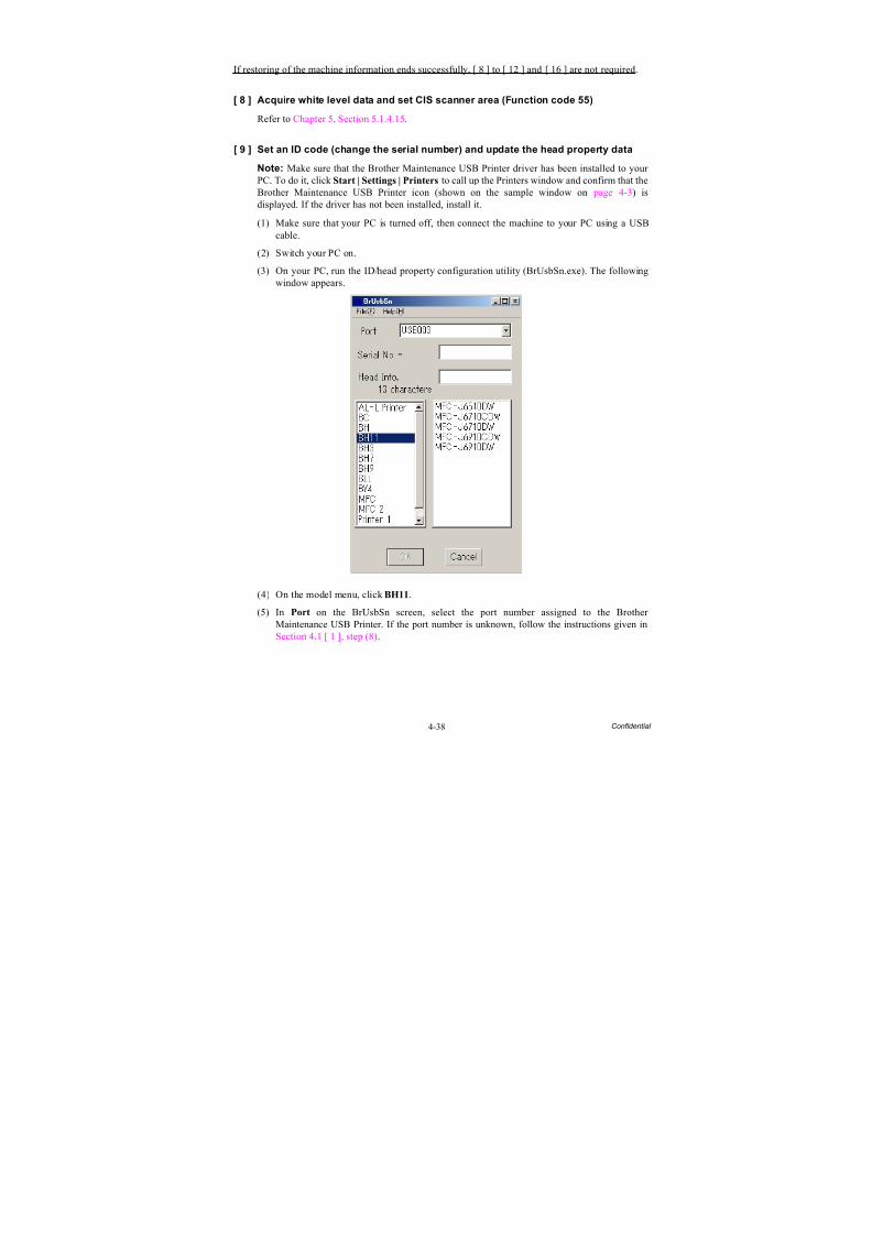
8/15/2019 Brother MFC 6510dw Sm
http://slidepdf.com/reader/full/brother-mfc-6510dw-sm 299/392
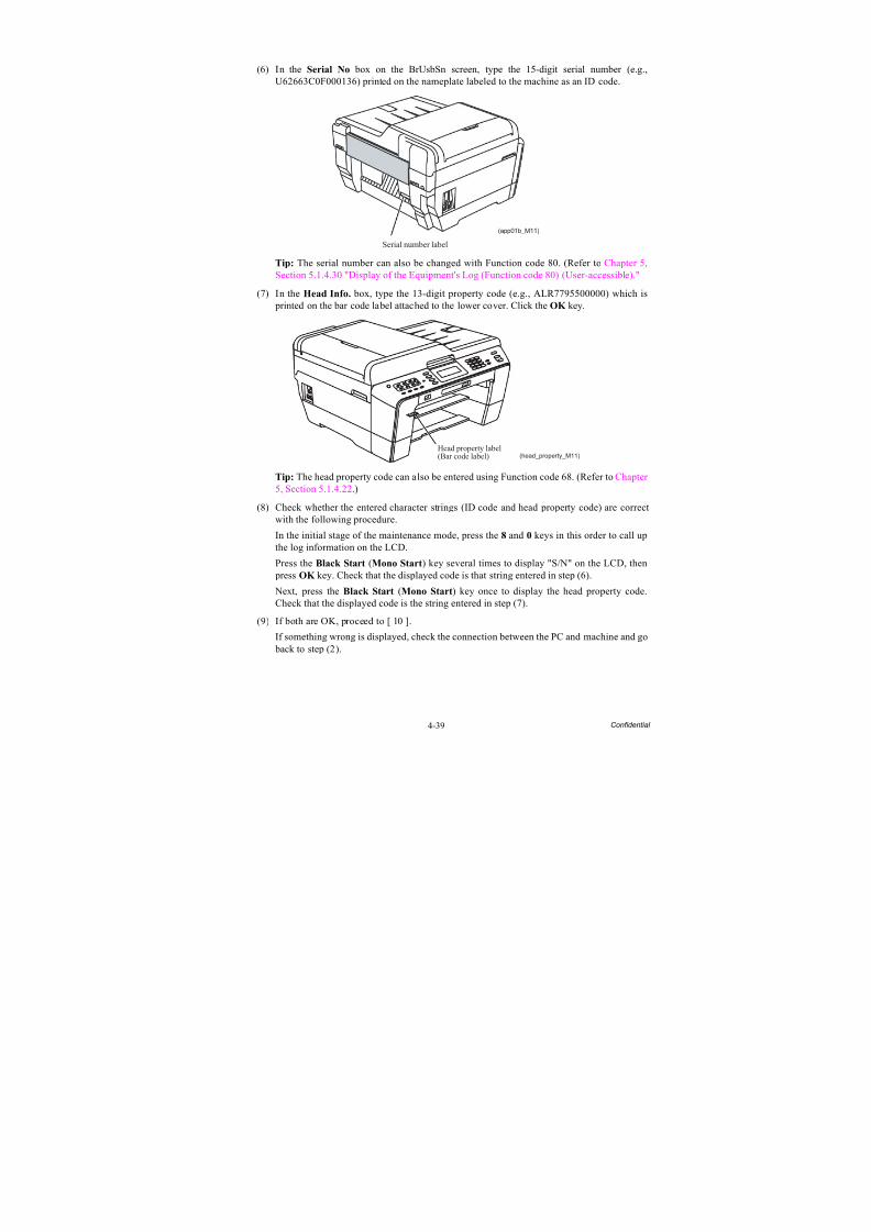
8/15/2019 Brother MFC 6510dw Sm
http://slidepdf.com/reader/full/brother-mfc-6510dw-sm 300/392
4-39 Confidential
(6) In the Serial No box on the BrUsbSn screen, type the 15-digit serial number (e.g.,U62663C0F000136) printed on the nameplate labeled to the machine as an ID code.
Tip: The serial number can also be changed with Function code 80. (Refer to Chapter 5,
Section 5.1.4.30 "Display of the Equipment's Log (Function code 80) (User-accessible)."(7) In the Head Info. box, type the 13-digit property code (e.g., ALR7795500000) which is
printed on the bar code label attached to the lower cover. Click the OK key.
Tip: The head property code can also be entered using Function code 68. (Refer to Chapter 5, Section 5.1.4.22.)
(8) Check whether the entered character strings (ID code and head property code) are correctwith the following procedure.
In the initial stage of the maintenance mode, press the 8 and 0 keys in this order to call upthe log information on the LCD.
Press the Black Start (Mono Start) key several times to display "S/N" on the LCD, then press OK key. Check that the displayed code is that string entered in step (6).
Next, press the Black Start (Mono Start) key once to display the head property code.Check that the displayed code is the string entered in step (7).
(9) If both are OK, proceed to [ 10 ].
If something wrong is displayed, check the connection between the PC and machine and go back to step (2).
Serial number label
(app01b_M11)
Head property label(Bar code label) (head_property_M11)
8/15/2019 Brother MFC 6510dw Sm
http://slidepdf.com/reader/full/brother-mfc-6510dw-sm 301/392
4-40 Confidential
[ 10 ] Update the paper feeding correction value (Function code 58)
Refer to Section 4.1 [ 5 ].
[ 11 ] Align vertical print lines (Function code 65)
Refer to Section 4.1 [ 7 ].
[ 12 ] Adjust margins in borderless printing (Function code 66)
Refer to Section 4.1 [ 8 ].
[ 13 ] Create head calibration data and write it into flash ROM (Function code 02)
Refer to Section 4.1 [ 9 ].
If restoring of head calibration data ends successfully in [ 6 ] above, this procedure is notrequired.
[ 14 ] Print out an ADF copy chart and make a copy of that chart in ADF scanning
Refer to Section 4.3 [ 1 ].
[ 15 ] Print out a total quality check pattern
Refer to Section 4.1 [ 11 ].
[ 16 ] Adjust the touch panel (Function code 78) (For models with touch panel)
Refer to Chapter 5, Section 5.1.4.29.
[ 17 ] Switch back to standby
Refer to Section 4.1 [ 12 ].
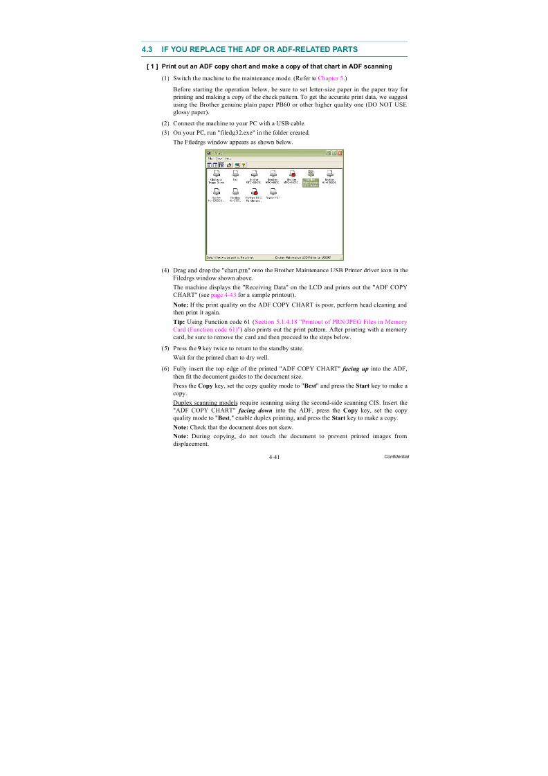
8/15/2019 Brother MFC 6510dw Sm
http://slidepdf.com/reader/full/brother-mfc-6510dw-sm 302/392
8/15/2019 Brother MFC 6510dw Sm
http://slidepdf.com/reader/full/brother-mfc-6510dw-sm 303/392
4-42 Confidential
(7) Check the copied chart, referring to the "Check Items on the ADF COPY CHART" given below.
If any problem is found, remove the newly mounted ADF unit or ADF-related parts onceand set it (them) into place, or check and correct the connection of ADF-related harnesses.
Note: Since the resolution of the second side scanning CIS unit is low, the copied chart
may have stripes or streaks; however, it is not a problem. Check it, referring to the "Check Items on the ADF COPY CHART" below.
Check Items on the ADF COPY CHART
Check that the copied chart has none of the following defects.
A: Contrast chart 1
• Black or white vertical streaks
• Patchy color
• Missing dotsB: Color blocks
• Patchy color
• In the second row, black block printed in yellow or red
• Area expansion of block(s)
• In the third row, blocks printed too dim to see
• Frames of white blocks missing or discolored
Note: Vertical streaks in color blocks are negligible.
C: Contrast chart 2
• Vertical streaks in 0.3 to 0.5 charts(Vertical streaks only in 0.2 chart are negligible.)
• Patchy color in 0.3 to 0.5 charts(Patchy color only in 0.2 chart is negligible.)
• Missing dots in 0.2 to 0.5 charts
D: Resolution chart
• Overlapping lines (diagonal or horizontal) in 4 to 6 mm charts
• Curved lines in 4 to 6 mm charts
• Black or color vertical streaks in 4 to 6 mm charts
• Discoloration in 4 to 6 mm charts
E: Whole page
• Ghost (image printed on the blank area)
• Color horizontal streaks
• Black vertical band
8/15/2019 Brother MFC 6510dw Sm
http://slidepdf.com/reader/full/brother-mfc-6510dw-sm 304/392
4-43 Confidential
ADF Copy Chart
C
A
B
D
8/15/2019 Brother MFC 6510dw Sm
http://slidepdf.com/reader/full/brother-mfc-6510dw-sm 305/392
4-44 Confidential
4.4 IF YOU REPLACE THE INK ABSORBER BOX OR FLUSHING BOX
When either the ink absorber box or flushing box is replaced, you should replace both of them.
[ 1 ] Reset each of the purge and flushing counters
(1) Switch the machine to the maintenance mode. (Refer to Chapter 5.)
(2) Press the 8 and 0 keys in this order.
(3) Press the Black Start (Mono Start) key several times until the purge (or flushing) countappears on the LCD.
(4) Press the 2, 7, 8, and 3 keys in this order to reset the purge (or flushing) count.
(5) Press the Stop/Exit key to return to the initial stage of the maintenance mode.
(6) Press the 9 key twice to exit from the maintenance mode.
Tip: This machine counts all purge operations and flushing operations performed since produced in order to prevent the ink absorber box and flushing box from overflowing withdrained and flushed ink, respectively. An initial purge, for example, advances the counter by155 + 413 = 568.
When the purge or flushing counter approaches 15350 or 698469595, respectively, the"MACHINE ERROR 46" appears and further purge or flushing operations are prohibited.Replace the ink absorber box and flushing box, and then reset their counters.
4.5 IF YOU REPLACE THE CONTROL PANEL ASSY, CONTROL PANEL
PCB OR LCD UNIT
[ 1 ] Adjust the touch panel (Function code 78) (For models with touch panel)
Refer to Chapter 5, Section 5.1.4.29.
Note: This operation is not required when only the control panel PCB is replaced.
[ 2 ] Check LCD operation (Function code 12)
Refer to Chapter 5, Section 5.1.4.7.
Note: This operation is not required when only the control panel PCB is replaced.
[ 3 ] Check the operation of the control panel PCB (Function code 13)
Refer to Chapter 5, Section 5.1.4.8.
Note: This operation is not required when only the LCD unit is replaced.

8/15/2019 Brother MFC 6510dw Sm
http://slidepdf.com/reader/full/brother-mfc-6510dw-sm 306/392
4-45 Confidential
4.6 IF YOU REPLACE THE FB UNIT* OR SCANNER COVER (SCANNER
UNIT)
* FB unit: ADF & document cover ASSY and scanner cover (scanner unit)
[ 1 ] Acquire white level data and set CIS scanner area (Function code 55)
Refer to Chapter 5, Section 5.1.4.15.
[ 2 ] Print out an ADF copy chart and make a copy of that chart in ADF scanning
Refer to Section 4.3 [ 1 ].
8/15/2019 Brother MFC 6510dw Sm
http://slidepdf.com/reader/full/brother-mfc-6510dw-sm 307/392
5-1 Confidential
CHAPTER 5 SERVICE FUNCTIONS
This chapter describes the maintenance mode and other service functions, which are exclusivelydesigned for the purpose of checks, settings and adjustments of the machine using the keys on the
control panel*.* Models with touch panel use also the keys of the software keypad displayed on the touch panel. Only
when a key needs to be limited to the one on the control panel or on the touch panel, this chapter describesa key, for example, as "the Copy key on the control panel" or "the Scan key on the touch panel." If adescription says just "the 5 key," you can use either the 5 key of the numerical keypad on the control panelor the 5 key of the software keypad on the touch panel.
5.1 MAINTENANCE MODE
In the maintenance mode, you can update memory (EEPROM: electrically erasable programmableread-only memory) contents for optimizing the drive conditions of the head/carriage unit or the paper feed roller and paper ejection roller in the engine unit, if those units have been replaced, or for settingthe CIS scanner area, for example. You can also customize the EEPROM according to the shipmentdestination of the machine concerned. In addition, you can perform operational checks of the LCD,control panel PCB or sensors, perform a print test, display the log information or error codes, andmodify firmware switches (WSW).
5.1.1 How to Enter the End User-accessible Maintenance Mode
Basically, the maintenance-mode functions listed in Section 5.1.3 should be accessed by service personnel only. However, you can allow end users to access some of these under the guidance
of service personnel (e.g., by telephone).
The user-accessible functions (codes 10 to 12, 46, 52, 53, 66, 75, 76, 80, 82, 87, 88, and 91) are shaded in the table given in Section 5.1.3. Function code 10 accesses the firmware switches,each of which has eight selectors. You should not allow end users to access all of thoseselectors, but you can allow them to access user-accessible selectors which are shaded in thefirmware switch tables in the "Firmware Switches (WSW)" document separately issued.
The service personnel should instruct end users to follow the procedure given below.
(1) Models without touch panel
Press the Menu, Black Start (Mono Start), and Menu keys in this order.
TIP: For models with numerical keypad, you may press the Menu, Black Start (Mono
Start), and 0 keys instead, in the same way as conventional models.
Models with touch panel
Press the Menu key on the touch panel (or the Scan and Copy keys on the control panelsimultaneously), the Black Start (Mono Start) key, and the PHOTO CAPTURE key (or the Scan and Copy keys simultaneously) in this order.
TIP: For models with numerical keypad on the control panel, you may press the Menu keyon the touch panel (or the Scan and Copy keys on the control panel simultaneously), theBlack Start (Mono Start) key, and the 0 key on the numerical keypad instead, in the same
way as conventional models.
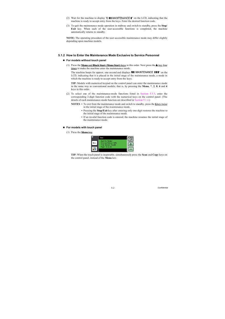
8/15/2019 Brother MFC 6510dw Sm
http://slidepdf.com/reader/full/brother-mfc-6510dw-sm 308/392
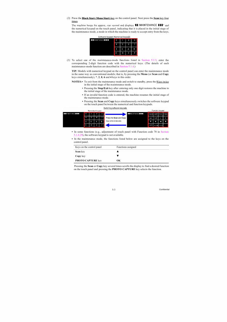
8/15/2019 Brother MFC 6510dw Sm
http://slidepdf.com/reader/full/brother-mfc-6510dw-sm 309/392
5-3 Confidential
(2) Press the Black Start (Mono Start) key on the control panel. Next press the Scan key four times.
The machine beeps for approx. one second and displays " " andthe numerical keypad on the touch panel, indicating that it is placed in the initial stage of the maintenance mode, a mode in which the machine is ready to accept entry from the keys.
(3) To select one of the maintenance-mode functions listed in Section 5.1.3, enter thecorresponding 2-digit function code with the numerical keys. (The details of eachmaintenance-mode function are described in Section 5.1.4.)
TIP: Models with numerical keypad on the control panel can enter the maintenance modein the same way as conventional models; that is, by pressing the Menu (or Scan and Copy
keys simultaneously), *, 2, 8, 6 and 4 keys in this order.
NOTES:• To exit from the maintenance mode and switch to standby, press the 9 key twicein the initial stage of the maintenance mode.
• Pressing the Stop/Exit key after entering only one digit restores the machine tothe initial stage of the maintenance mode.
• If an invalid function code is entered, the machine resumes the initial stage of the maintenance mode.
• Pressing the Scan and Copy keys simultaneously switches the software keypadon the touch panel between the numerical and function keypads.
• In some functions (e.g., adjustment of touch panel with Function code 78 in Section5.1.4.29), the software keypad is not available.
• In the maintenance mode, the functions listed below are assigned to the keys on thecontrol panel.
Pressing the Scan or Copy key several times scrolls the display to find a desired functionon the touch panel and pressing the PHOTO CAPTURE key selects the function.
Keys on the control panel Functions assigned
Scan key
Copy key
PHOTO CAPTURE key OK
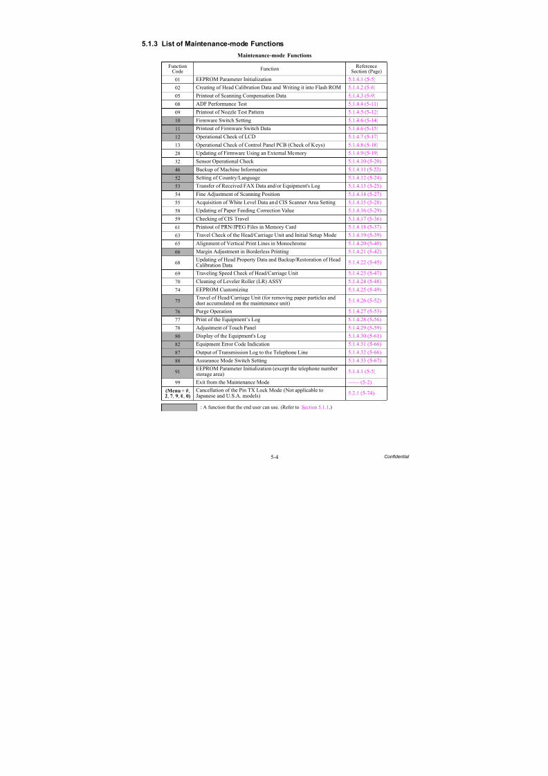
8/15/2019 Brother MFC 6510dw Sm
http://slidepdf.com/reader/full/brother-mfc-6510dw-sm 310/392
5-4 Confidential
5.1.3 List of Maintenance-mode Functions
Maintenance-mode Functions
FunctionCode Function Reference
Section (Page)
01 EEPROM Parameter Initialization 5.1.4.1 (5-5)
02 Creating of Head Calibration Data and Writing it into Flash ROM 5.1.4.2 (5-6)05 Printout of Scanning Compensation Data 5.1.4.3 (5-9)
08 ADF Performance Test 5.1.4.4 (5-11)
09 Printout of Nozzle Test Pattern 5.1.4.5 (5-12)
10 Firmware Switch Setting 5.1.4.6 (5-14)
11 Printout of Firmware Switch Data 5.1.4.6 (5-15)
12 Operational Check of LCD 5.1.4.7 (5-17)
13 Operational Check of Control Panel PCB (Check of Keys) 5.1.4.8 (5-18)
28 Updating of Firmware Using an External Memory 5.1.4.9 (5-19)
32 Sensor Operational Check 5.1.4.10 (5-20)
46 Backup of Machine Information 5.1.4.11 (5-22)
52 Setting of Country/Language 5.1.4.12 (5-24)
53 Transfer of Received FAX Data and/or Equipment's Log 5.1.4.13 (5-25)
54 Fine Adjustment of Scanning Position 5.1.4.14 (5-27)
55 Acquisition of White Level Data and CIS Scanner Area Setting 5.1.4.15 (5-28)
58 Updating of Paper Feeding Correction Value 5.1.4.16 (5-29)
59 Checking of CIS Travel 5.1.4.17 (5-36)
61 Printout of PRN/JPEG Files in Memory Card 5.1.4.18 (5-37)
63 Travel Check of the Head/Carriage Unit and Initial Setup Mode 5.1.4.19 (5-39)
65 Alignment of Vertical Print Lines in Monochrome 5.1.4.20 (5-40)
66 Margin Adjustment in Borderless Printing 5.1.4.21 (5-42)
68 Updating of Head Property Data and Backup/Restoration of HeadCalibration Data 5.1.4.22 (5-45)
69 Traveling Speed Check of Head/Carriage Unit 5.1.4.23 (5-47)
70 Cleaning of Leveler Roller (LR) ASSY 5.1.4.24 (5-48)
74 EEPROM Customizing 5.1.4.25 (5-49)
75Travel of Head/Carriage Unit (for removing paper particles anddust accumulated on the maintenance unit) 5.1.4.26 (5-52)
76 Purge Operation 5.1.4.27 (5-53)
77 Print of the Equipment’s Log 5.1.4.28 (5-56)
78 Adjustment of Touch Panel 5.1.4.29 (5-59)
80 Display of the Equipment's Log 5.1.4.30 (5-61)
82 Equipment Error Code Indication 5.1.4.31 (5-66)
87 Output of Transmission Log to the Telephone Line 5.1.4.32 (5-66)
88 Assurance Mode Switch Setting 5.1.4.33 (5-67)
91EEPROM Parameter Initialization (except the telephone numberstorage area) 5.1.4.1 (5-5)
99 Exit from the Maintenance Mode ------ (5-2)
(Menu + #,2, 7, 9, 0, 0)
Cancellation of the Pin TX Lock Mode (Not applicable toJapanese and U.S.A. models) 5.2.1 (5-74)
: A function that the end user can use. (Refer to Section 5.1.1.)
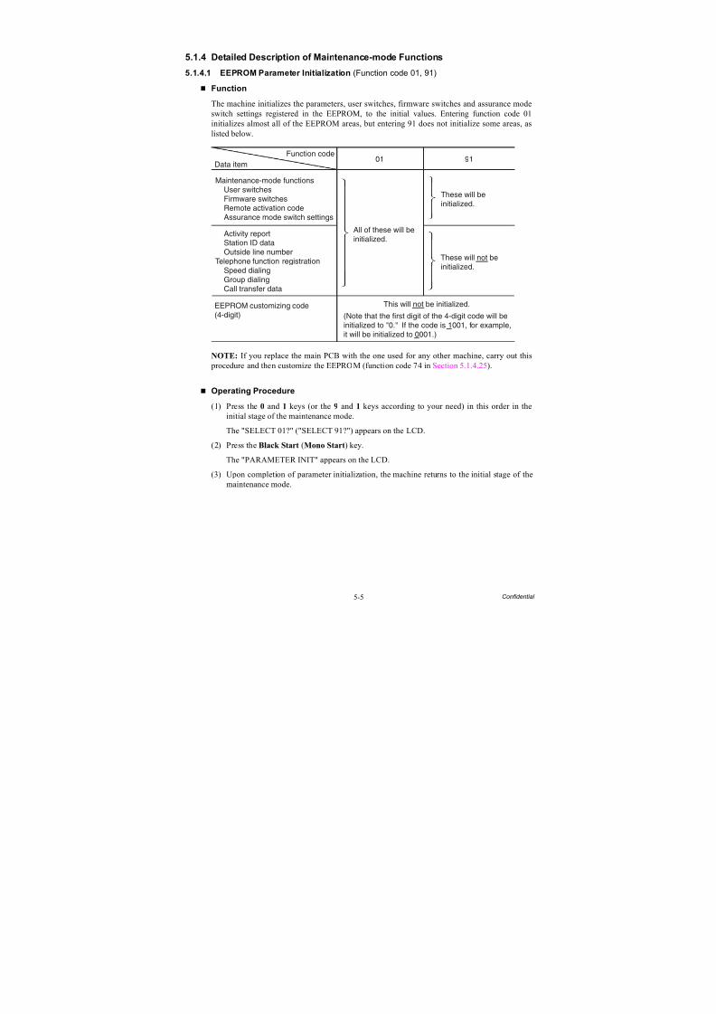
8/15/2019 Brother MFC 6510dw Sm
http://slidepdf.com/reader/full/brother-mfc-6510dw-sm 311/392
5-5 Confidential
5.1.4 Detailed Description of Maintenance-mode Functions
5.1.4.1 EEPROM Parameter Initialization (Function code 01, 91)
Function
The machine initializes the parameters, user switches, firmware switches and assurance mode
switch settings registered in the EEPROM, to the initial values. Entering function code 01initializes almost all of the EEPROM areas, but entering 91 does not initialize some areas, aslisted below.
NOTE: If you replace the main PCB with the one used for any other machine, carry out this procedure and then customize the EEPROM (function code 74 in Section 5.1.4.25).
Operating Procedure
(1) Press the 0 and 1 keys (or the 9 and 1 keys according to your need) in this order in theinitial stage of the maintenance mode.
The "SELECT 01?" ("SELECT 91?") appears on the LCD.
(2) Press the Black Start (Mono Start) key.
The "PARAMETER INIT" appears on the LCD.
(3) Upon completion of parameter initialization, the machine returns to the initial stage of themaintenance mode.
Function code
Maintenance-mode functions User switches Firmware switches Remote activation code Assurance mode switch settings
Activity report Station ID data Outside line numberTelephone function registration Speed dialing Group dialing Call transfer data
EEPROM customizing code(4-digit)
All of these will beinitialized.
These will beinitialized.
These will not beinitialized.
This will not be initialized.
(Note that the first digit of the 4-digit code will beinitialized to "0." If the code is 1001, for example,it will be initialized to 0001.)
Data item01 91
8/15/2019 Brother MFC 6510dw Sm
http://slidepdf.com/reader/full/brother-mfc-6510dw-sm 312/392
5-6 Confidential
5.1.4.2 Creating of Head Calibration Data and Writing it into Flash ROM
(Function code 02)
Function
This procedure scans the "Print pattern for creating head calibration data" sheet (see page 5-8) placed on the scanner glass of the document cover, creates the head calibration data using thescanning result, and writes it into the flash ROM on the main PCB.
Operating Procedure
Notes • Before proceeding to the procedure given below, use Function code 55 (described inSection 5.1.4.15 "Acquisition of White Level Data and CIS Scanner Area Setting(Function code 55)"). If not, this function may fail to create head calibration datacorrectly.
• Make sure that all of the scanner cover (scanner unit), document cover and ADF cover are closed.
• For higher precision of uneven printing correction, use the recording paper specified
below to print the "pattern for creating head calibration data."US: Xerox 4200DP 20 lb., Brother BP60PLEU, AP and others: Xerox Business 80 g/m2, Brother BP60PA
(1) Drag and drop the "head_calib.prn" onto the Brother Maintenance USB Printer driver iconin the Filedrgs window.
The machine displays the "RECEIVING DATA" on the LCD and prints out "Print patternfor creating head calibration data" (see page 5-8 for a sample printout).
Tip: Using Function code 61 (Section 5.1.4.18 "Printout of PRN/JPEG Files in MemoryCard (Function code 61)") also prints out the print pattern. After printing with a memorycard, be sure to remove the card and then proceed to the steps below.
Note: Make sure that the USB cable is disconnected.
(2) Set the print pattern on the scanner glass of the document cover.
(3) Press the 0 and 2 keys in this order in the initial stage of the maintenance mode.
The "MAINTENANCE 02" and "Set Sheet on FB?" appear on the LCD in this order.
Note: Pressing the Stop/Exit key immediately returns the machine to the initial stage of themaintenance mode without creating head calibration data.
(4) Press the Black Start (Mono Start) key.
The machine displays the "Scanning" on the LCD and starts scanning the "Print pattern for creating head calibration data" placed on the scanner glass.
Upon completion of scanning, the machine displays the "Write Head Calib" on the LCD,creates the head calibration data, and writes it into the flash ROM on the main PCB.
Upon completion of writing, the "Complete" appears. Press the Stop/Exit key to return tothe initial stage of the maintenance mode.
Note: If an error occurs, the machine beeps and displays "Error No **" on the LCD. Pressthe Stop/Exit key to return to the initial stage of the maintenance mode and then recover the machine from the error state, following the table given on the next page. Then go back to step (2).
8/15/2019 Brother MFC 6510dw Sm
http://slidepdf.com/reader/full/brother-mfc-6510dw-sm 313/392
5-7 Confidential
Error code The following error has occurred. Do the following:
01 Failed to detect the external frame. • Clean the scanner glass.• Reposition a document along the
document guides on the document
cover.• Go back to step (1) and print out "Print
pattern for creating head calibrationdata" again.
02 Internal image inclined.
03 Failed to detect position.
04 Failed to write head calibration data. • Clean the scanner glass.
• Reposition a document along thedocument guides on the documentcover.
• Restart the machine and perform thefunction again.
• Replace the main PCB.
05 The uneven printing correctionfunction for upper and lower ends ofthe nozzle is disabled with Functioncode 88.
• Use Function code 88 (in Section5.1.4.33 "Assurance Mode SwitchSetting (Function code 88) (User-accessible)") to set selector 1 on AMS05to "0."
06 Cannot get memory space. • Delete stored data including fax data.• Stop any other function if being used.• Replace the main PCB.
07 The scanner cover (scanner unit) isopen.
• Close the scanner cover.• Reconnect the panel-main harness.
• Reposition the scanner cover sensoractuator.
• Replace the rubber keypad(s).• Replace the control panel PCB.
• Replace the scanner cover.• Replace the main PCB.
08 The ADF cover is open. • Close the ADF cover.• Reconnect the ADF cover switch
harness.
• Replace the ADF cover.• Replace the ADF harness unit.• Replace the main PCB.
09 Other scanning errors • Use Function code 55 (Section 5.1.4.15"Acquisition of White Level Data andCIS Scanner Area Setting (Functioncode 55)").
10 A media is inserted and also the USBcable or LAN cable is connected.
• Disconnect the USB cable.
8/15/2019 Brother MFC 6510dw Sm
http://slidepdf.com/reader/full/brother-mfc-6510dw-sm 314/392
5-8 Confidential
Print Pattern for Creating Head Calibration Data
8/15/2019 Brother MFC 6510dw Sm
http://slidepdf.com/reader/full/brother-mfc-6510dw-sm 315/392
5-9 Confidential
5.1.4.3 Printout of Scanning Compensation Data (Function code 05)
Function
The machine prints out the white and black level data for scanning compensation.
Operating Procedure
Do not start this function merely after powering on the machine but start it after carrying out asequence of scanning operation. Unless the machine has carried out any scanning operation,this function cannot print out correct scanning compensation data. This is because at the start of scanning operation, the machine initializes white and black level data and takes in the scanningcompensation reference data.
NOTE: If this function is used after monochrome scanning, only the green data is valid.
NOTE: Be sure to disconnect the USB cable from the machine before proceeding to the procedure below.
(1) Press the 0 and 5 keys in this order in the initial stage of the maintenance mode.
Simplex scanning models
The "DUMP 0:GRA 1:ALL" appears on the LCD.
Duplex scanning models
The "CIS 0:FB 1:ADF" appears on the LCD. To print compensation data for the first sidescanning CIS, press the 0 key; to print for the second side scanning CIS, press the 1 key.
The LCD shows "DUMP 0:GRA 1: ALL."
(2) Press the 0 key to print out a) through k) of the scanning compensation data list detailed below and shown on the next page; press the 1 key to print out all of a) through o).
During printing, the "PRINTING" is displayed on the LCD.
The scanning compensation data list contains the following:
a) Black/white data graph b) LED light intensity PWM data for color image (1 byte)
c) LED light intensity PWM data for monochrome image (1 byte)
d) LED light intensity pulse data for green image (2 bytes)
e) LED light intensity pulse data for blue image (2 bytes)
f) LED light intensity pulse data for red image (2 bytes)
g) LED light intensity pulse data for monochrome image (2 bytes)
h) AFE RLCV*1 data (1 byte)
i) AFE offset data (1 byte)
j) AFE gain data (1 byte)
k) Background color compensation data*2 (1 byte)
l) Black level data*3
m)White level data for red image*3
n) White level data for green image*3
o) White level data for blue image*3
*1 AFE: Analog Front EndRLCV: Reset Level Clamp Voltage
*2 Data for background color compensation (filtering out background color) to be performed inmonochrome copying of a document printed on colored paper.
*3 Last scanned data, any of the 3504 bytes in 300 dpi, 7016 bytes in 600 dpi, or 14040 bytes in1200 dpi, 28080 bytes in 2400 dpi.
(3) Upon completion of printing of the compensation data list, the machine returns to the initial
stage of the maintenance mode.NOTE: If any data is abnormal, its code will be printed in inline style.
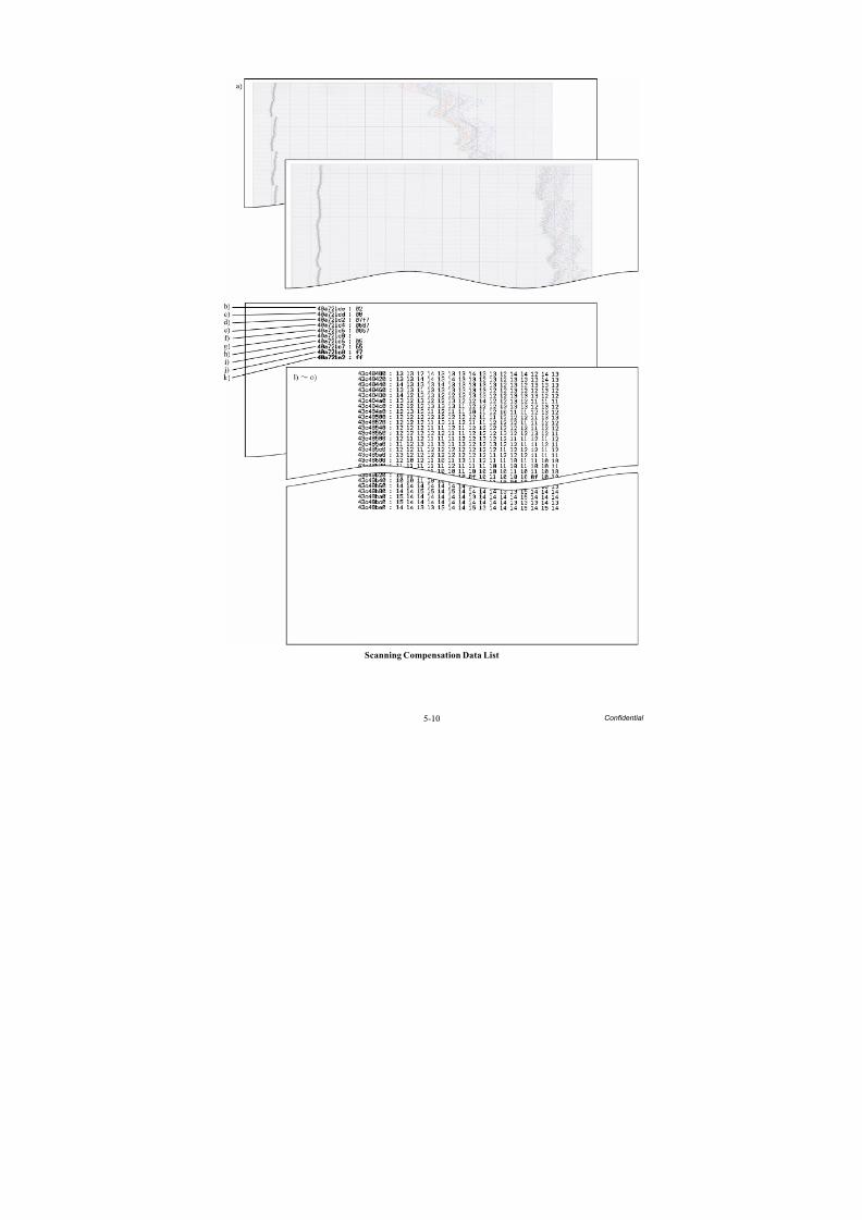
8/15/2019 Brother MFC 6510dw Sm
http://slidepdf.com/reader/full/brother-mfc-6510dw-sm 316/392
5-10 Confidential
Scanning Compensation Data List

8/15/2019 Brother MFC 6510dw Sm
http://slidepdf.com/reader/full/brother-mfc-6510dw-sm 317/392
5-11 Confidential
5.1.4.4 ADF Performance Test (Function code 08)
Function
The machine counts the documents fed by the automatic document feeder (ADF) and displaysthe count on the LCD for checking the ADF performance.
Operating Procedure
(1) Set documents. (Allowable up to the ADF capacity.)
The "DOC. READY" appears on the LCD.
(2) Press the 0 and 8 keys in this order in the initial stage of the maintenance mode.
The machine feeds the documents in and out while counting them and displaying thecurrent count on the LCD as shown below.
(3) After counting all documents, the machine shows the final count. To return the machine tothe initial stage of the maintenance mode, press the Stop/Exit key.
ADF CHK P.01
Current count (1st page in this example)

8/15/2019 Brother MFC 6510dw Sm
http://slidepdf.com/reader/full/brother-mfc-6510dw-sm 318/392
5-12 Confidential
5.1.4.5 Printout of Nozzle Test Pattern (Function code 09)
Function
This function prints out a nozzle test pattern (Print Quality Check sheet) to allow the service personnel to check the print quality.
If any print quality problem is found, use Function code 76 to perform an appropriate purgeoperation (refer to Section 5.1.4.27).
Operating Procedure
Before starting the operation below, be sure to set letter- or A4-size paper in the paper tray for
printing test patterns.
Press the 0 and 9 keys in this order in the initial stage of the maintenance mode.
The figure on the next page shows a test pattern which is printed on the Print Quality Check sheet.
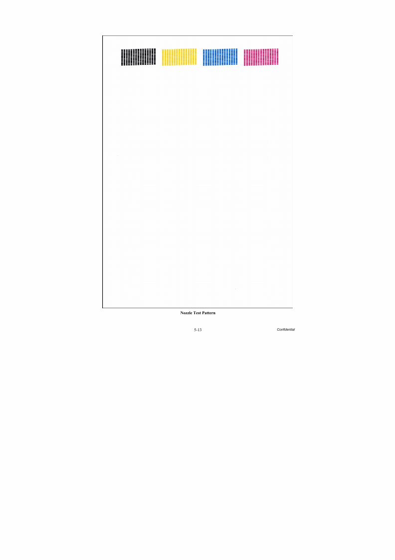
8/15/2019 Brother MFC 6510dw Sm
http://slidepdf.com/reader/full/brother-mfc-6510dw-sm 319/392
5-13 Confidential
Nozzle Test Pattern
8/15/2019 Brother MFC 6510dw Sm
http://slidepdf.com/reader/full/brother-mfc-6510dw-sm 320/392
5-14 Confidential
5.1.4.6 Firmware Switch Setting and Printout (Function codes 10 and 11)
(User-accessible)
[ A ] Firmware switch setting
Function
The machine incorporates the firmware switch functions which can be activated with the procedures using the control panel keys.
For details about the firmware switches, refer to the "Firmware Switches (WSW)" documentseparately issued.
The firmware switches have been configured at the factory in conformity to thecommunications standards and codes of each country. Do not disturb them unless necessary.Some firmware switches may not be applicable in some versions. The firmware switch data listindicates "Not used." for those inapplicable switches.
Operating Procedure
(1) Press the 1 and 0 keys in this order in the initial stage of the maintenance mode.
The machine displays the "WSW00" on the LCD and becomes ready to accept a firmwareswitch number.
(2) Enter the desired number from the firmware switch numbers (01 through 60).
The following appears on the LCD:
Selector 1 Selector 8
↓ ↓
WSWXX = 0 0 0 0 0 0 0 0
(3) Use the and keys to move the cursor to the selector position to be modified.
NOTE: In models with touch panel, if the , , , and keys are not displayed on thesoftware keypad, it is necessary to switch the software keypads between the numerical andfunction keypads by pressing the Scan and Copy keys simultaneously.
(4) Enter the desired number using the 0 and 1 keys.
(5) Press the OK key (PHOTO CAPTURE key for models without OK key). This operationsaves the newly entered selector values onto the EEPROM and readies the machine for accepting a firmware switch number.
NOTE: Pressing the Stop/Exit key instead of the OK key returns the machine to the initialstage of the maintenance mode without saving new setting.
(6) Repeat steps (2) through (5) until the modification for the desired firmware switches iscompleted.
(7) Press the Stop/Exit key to return the machine to the initial stage of the maintenance mode.
NOTE: If there is a pause of more than one minute after a single-digit number is entered for double-digit firmware switch numbers, the machine automatically returns to the initial stage of the maintenance mode.

8/15/2019 Brother MFC 6510dw Sm
http://slidepdf.com/reader/full/brother-mfc-6510dw-sm 321/392
5-15 Confidential
[ B ] Printout of firmware switch data
Function
The machine prints out the setting items of the firmware switches and their contents specified.
Operating Procedure
(1) Press the 1 key twice in the initial stage of the maintenance mode.
The machine shows "PRINTING" on the LCD and prints out the configuration list asshown on the next page.
Upon completion of printing, the machine returns to the initial stage of the maintenancemode.
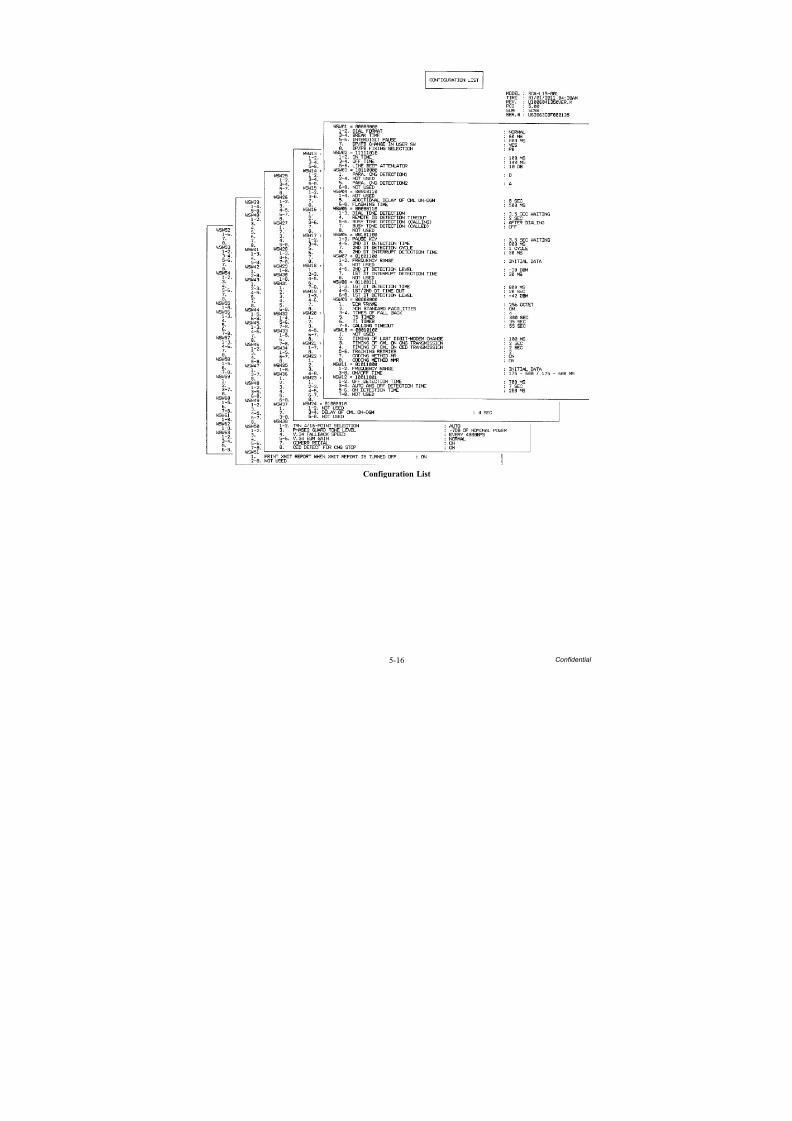
8/15/2019 Brother MFC 6510dw Sm
http://slidepdf.com/reader/full/brother-mfc-6510dw-sm 322/392
5-16 Confidential
Configuration List
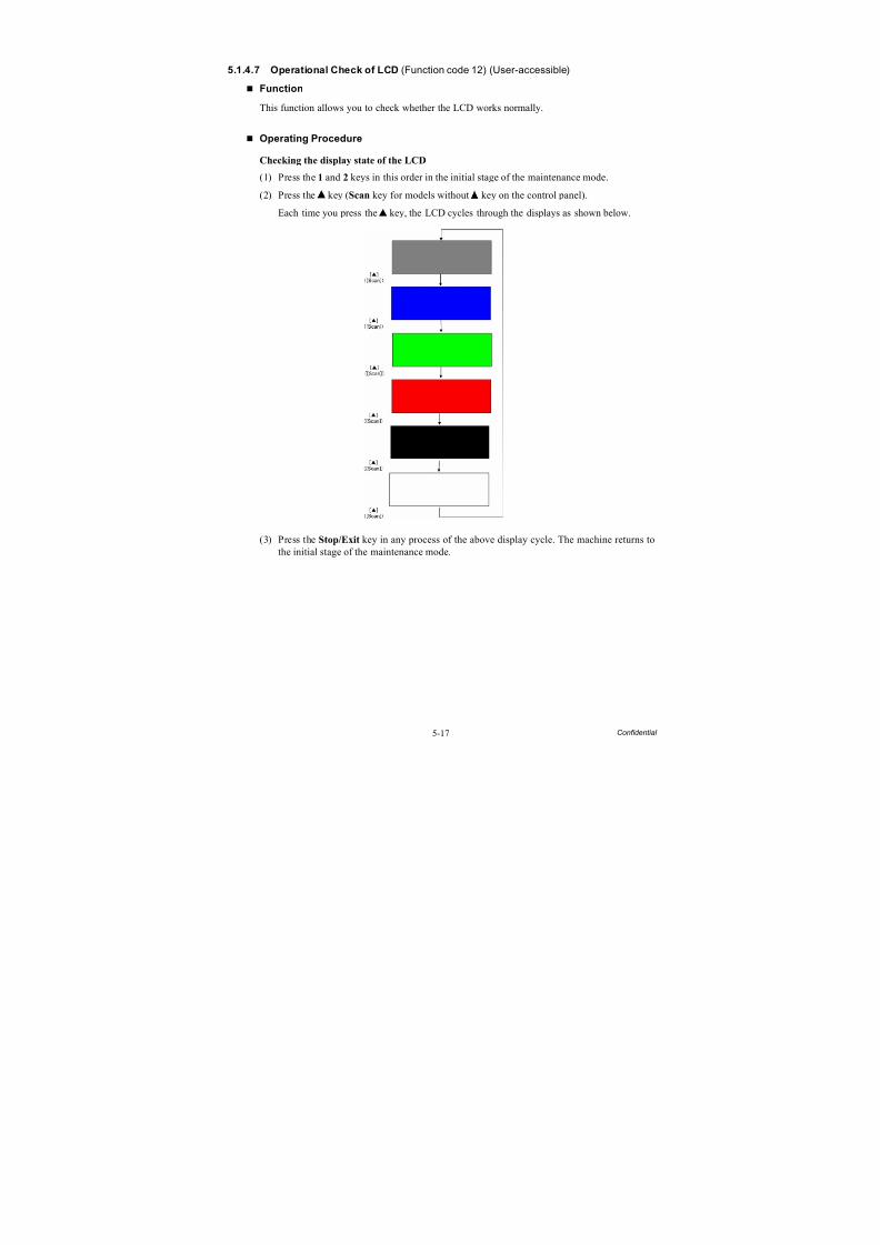
8/15/2019 Brother MFC 6510dw Sm
http://slidepdf.com/reader/full/brother-mfc-6510dw-sm 323/392
5-17 Confidential
5.1.4.7 Operational Check of LCD (Function code 12) (User-accessible)
Function
This function allows you to check whether the LCD works normally.
Operating Procedure
Checking the display state of the LCD
(1) Press the 1 and 2 keys in this order in the initial stage of the maintenance mode.
(2) Press the key (Scan key for models without key on the control panel).
Each time you press the key, the LCD cycles through the displays as shown below.
(3) Press the Stop/Exit key in any process of the above display cycle. The machine returns tothe initial stage of the maintenance mode.
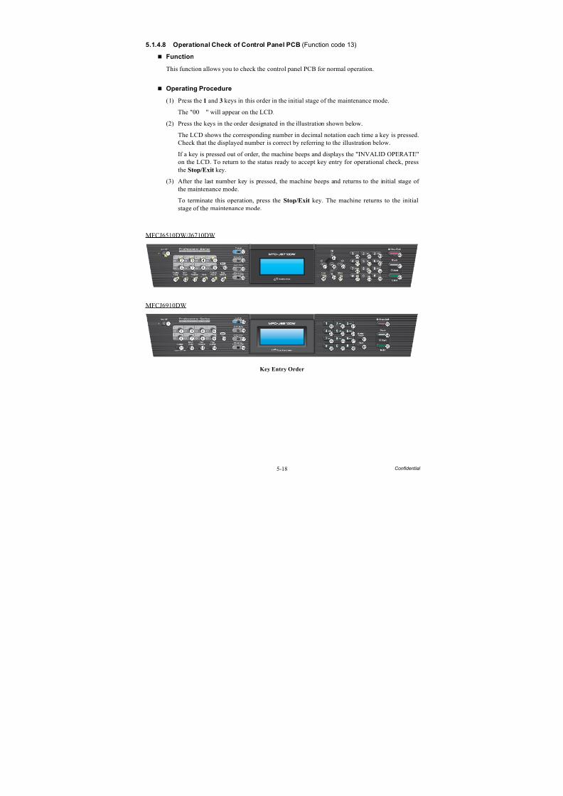
8/15/2019 Brother MFC 6510dw Sm
http://slidepdf.com/reader/full/brother-mfc-6510dw-sm 324/392
5-18 Confidential
5.1.4.8 Operational Check of Control Panel PCB(Function code 13)
Function
This function allows you to check the control panel PCB for normal operation.
Operating Procedure
(1) Press the 1 and 3 keys in this order in the initial stage of the maintenance mode.
The "00 " will appear on the LCD.
(2) Press the keys in the order designated in the illustration shown below.
The LCD shows the corresponding number in decimal notation each time a key is pressed.Check that the displayed number is correct by referring to the illustration below.
If a key is pressed out of order, the machine beeps and displays the "INVALID OPERATE"on the LCD. To return to the status ready to accept key entry for operational check, pressthe Stop/Exit key.
(3) After the last number key is pressed, the machine beeps and returns to the initial stage of the maintenance mode.
To terminate this operation, press the Stop/Exit key. The machine returns to the initialstage of the maintenance mode.
MFCJ6510DW/J6710DW
MFCJ6910DW
Key Entry Order
36
8/15/2019 Brother MFC 6510dw Sm
http://slidepdf.com/reader/full/brother-mfc-6510dw-sm 325/392
5-19 Confidential
5.1.4.9 Updating of Firmware Using an External Memory(Function code 28)
Function
This function updates firmware stored in the flash ROM on the main PCB using an externalmemory (memory card or USB flash memory). It enables updating of firmware withoutconnecting the machine to a PC.
TIP: For instructions on how to update firmware when the main PCB has been replaced or for operations using a PC, refer to Chapter 4, Section 4.2, [ 1 ].
Operating Procedure
(1) Switch your PC ON and insert an external memory.
(2) Create a folder named "BROTHER" in the top layer of the external memory's directory andcopy the firmware file having the extension .pjl into that folder.
NOTE: Before copying, check that the file name of the firmware matches with your machine. Be sure to save only one firmware file having the extension .pjl in the"BROTHER" folder. Otherwise, the firmware cannot be updated correctly.
TIP: If a firmware file not matching the machine is used, the firmware cannot be updated, but note that you can superficially continue the operation until step (5) below without anyerror.
TIP: For instructions on how to obtain the firmware file, refer to Chapter 4, Section 4.2,[ 1 ].
(3) Remove the external memory from the PC and insert it into the machine in the initial stageof the maintenance mode.
NOTE: Do not insert more than one external memory at a time.
NOTE: When performing this procedure for any other machine with the same externalmemory, delete the data previously stored in the external memory.
(4) On the machine, press the 2 and 8 keys in this order.The file name ********.pjl appears on the LCD. Check that ******** is identical with thefile name that has been copied into the external memory.
(5) Press the Black Start (Mono Start) key to start updating.
The "Receiving Data" appears on the LCD, and after a while, it changes to "ProgramUpdating."
NOTE: Pressing the Color Start key in this step does not start updating.
NOTE: Never remove the external memory from the machine when updating is in progress.
(6) Updating will complete in a few minutes, and the machine automatically restarts and
returns to the standby state.Remove the external memory from the machine and store it in a safe place.
NOTE 1: If any of the error messages listed below appears, press the Stop/Exit key, and themachine returns to the initial stage of the maintenance mode.
NOTE 2: After the completion of firmware updating, a file named "mfu-send.log" (whichstores the execution log) is created in the layer right below the "BROTHER" folder.
Error Message CauseCard is used The external memory is being used by another operation.
Insert Card No external memory is inserted.
No file - No "BROTHER" folder in the external memory- Invalid file name
Too many files There is more than one file having the extension .pjl in the folder.Card Error External memory defective
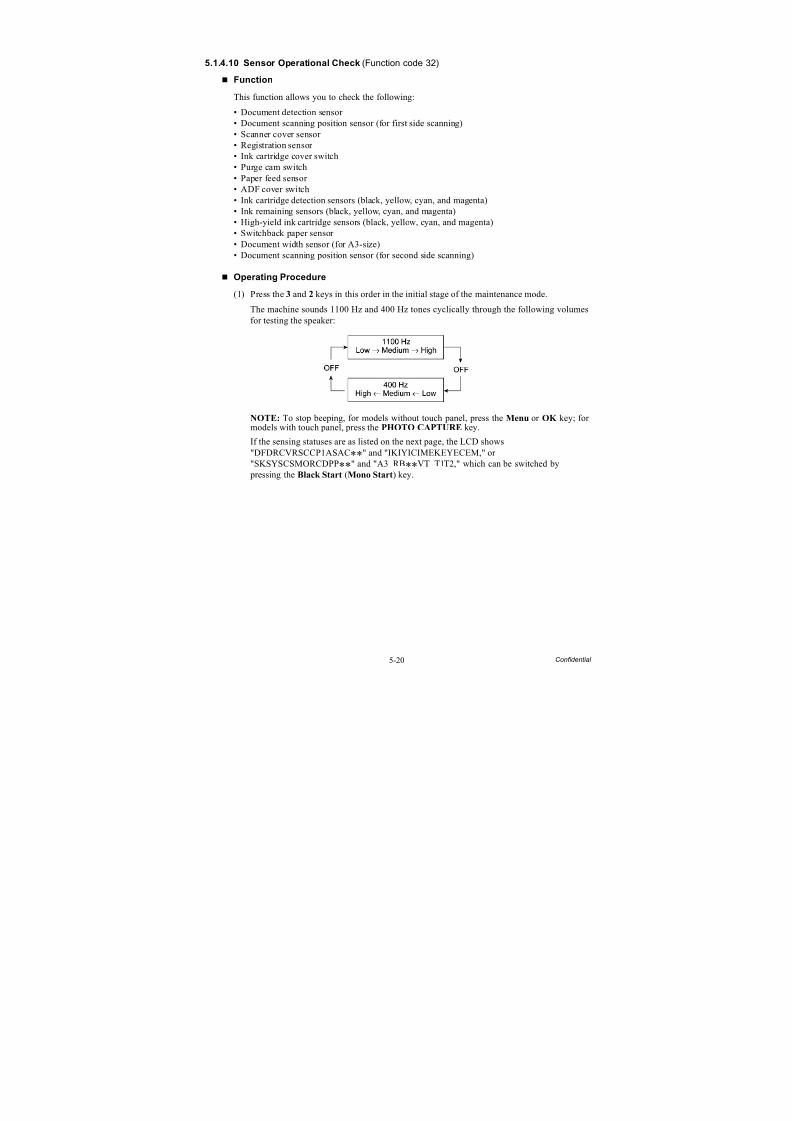
8/15/2019 Brother MFC 6510dw Sm
http://slidepdf.com/reader/full/brother-mfc-6510dw-sm 326/392
5-20 Confidential
5.1.4.10 Sensor Operational Check(Function code 32)
Function
This function allows you to check the following:
• Document detection sensor
• Document scanning position sensor (for first side scanning)• Scanner cover sensor • Registration sensor • Ink cartridge cover switch• Purge cam switch• Paper feed sensor • ADF cover switch• Ink cartridge detection sensors (black, yellow, cyan, and magenta)• Ink remaining sensors (black, yellow, cyan, and magenta)• High-yield ink cartridge sensors (black, yellow, cyan, and magenta)• Switchback paper sensor • Document width sensor (for A3-size)• Document scanning position sensor (for second side scanning)
Operating Procedure
(1) Press the 3 and 2 keys in this order in the initial stage of the maintenance mode.
The machine sounds 1100 Hz and 400 Hz tones cyclically through the following volumesfor testing the speaker:
NOTE: To stop beeping, for models without touch panel, press the Menu or OK key; for models with touch panel, press the PHOTO CAPTURE key.
If the sensing statuses are as listed on the next page, the LCD shows"DFDRCVRSCCP1ASAC**" and "IKIYICIMEKEYECEM," or"SKSYSCSMORCDPP**" and "A3 RB**VT T1T2," which can be switched by pressing the Black Start (Mono Start) key.
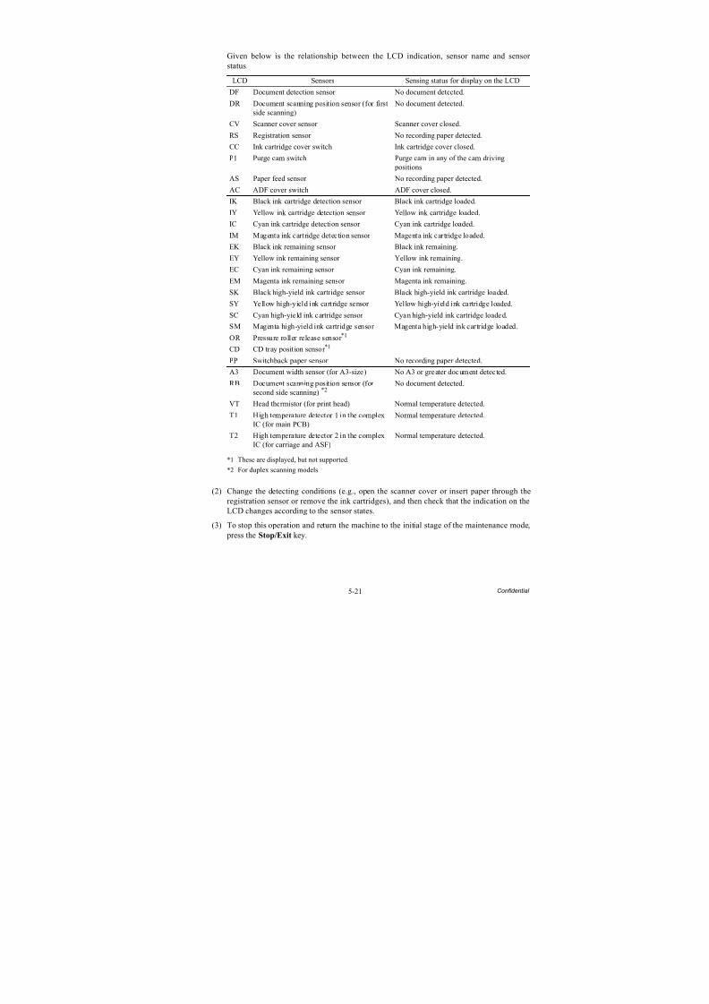
8/15/2019 Brother MFC 6510dw Sm
http://slidepdf.com/reader/full/brother-mfc-6510dw-sm 327/392
5-21 Confidential
Given below is the relationship between the LCD indication, sensor name and sensor status.
*1 These are displayed, but not supported.
*2 For duplex scanning models
(2) Change the detecting conditions (e.g., open the scanner cover or insert paper through theregistration sensor or remove the ink cartridges), and then check that the indication on theLCD changes according to the sensor states.
(3) To stop this operation and return the machine to the initial stage of the maintenance mode, press the Stop/Exit key.
LCD Sensors Sensing status for display on the LCD
DF Document detection sensor No document detected.
DR Document scanning position sensor (for first
side scanning)
No document detected.
CV Scanner cover sensor Scanner cover closed.
RS Registration sensor No recording paper detected.
CC Ink cartridge cover switch Ink cartridge cover closed.
P1 Purge cam switch Purge cam in any of the cam driving positions
AS Paper feed sensor No recording paper detected.
AC ADF cover switch ADF cover closed.
IK Black ink cartridge detection sensor Black ink cartridge loaded.
IY Yellow ink cartridge detection sensor Yellow ink cartridge loaded.
IC Cyan ink cartridge detection sensor Cyan ink cartridge loaded.IM Magenta ink cartridge detection sensor Magenta ink cartridge loaded.
EK Black ink remaining sensor Black ink remaining.
EY Yellow ink remaining sensor Yellow ink remaining.
EC Cyan ink remaining sensor Cyan ink remaining.
EM Magenta ink remaining sensor Magenta ink remaining.
SK Black high-yield ink cartridge sensor Black high-yield ink cartridge loaded.
SY Yellow high-yield ink cartridge sensor Yellow high-yield ink cartridge loaded.
SC Cyan high-yield ink cartridge sensor Cyan high-yield ink cartridge loaded.
SM Magenta high-yield ink cartridge sensor Magenta high-yield ink cartridge loaded.
OR Pressure roller release sensor *1
CD CD tray position sensor *1
PP Switchback paper sensor No recording paper detected.
A3 Document width sensor (for A3-size) No A3 or greater document detected.
RB Document scanning position sensor (forsecond side scanning) *2
No document detected.
VT Head thermistor (for print head) Normal temperature detected.
T1 High temperature detector 1 in the complexIC (for main PCB)
Normal temperature detected.
T2 High temperature detector 2 in the complexIC (for carriage and ASF)
Normal temperature detected.
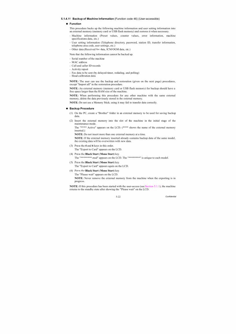
8/15/2019 Brother MFC 6510dw Sm
http://slidepdf.com/reader/full/brother-mfc-6510dw-sm 328/392
5-22 Confidential
5.1.4.11 Backup of Machine Information (Function code 46) (User-accessible)
Function
This procedure backs up the following machine information and user setting information intoan external memory (memory card or USB flash memory) and restores it when necessary.
- Machine information (Preset values, counter values, error information, machinespecifications data, etc.)
- User setting information (Telephone directory, password, station ID, transfer information,telephone area code, user settings, etc.)
- Other data (Received fax data, ICM/OGM data, etc.)
Note that the following information cannot be backed up.
- Serial number of the machine- MAC address- Call and caller ID records- Activity report- Fax data to be sent (by delayed-timer, redialing, and polling)- Head calibration data
NOTE: The user can use the backup and restoration (given on the next page) procedures,except "Import all" in the restoration procedure.
NOTE: An external memory (memory card or USB flash memory) for backup should have afree space larger than the RAM size of the machine.
NOTE: When performing this procedure for any other machine with the same externalmemory, delete the data previously stored in the external memory.
NOTE: Do not use a Memory Stick; using it may fail to transfer data correctly.
Backup Procedure
(1) On the PC, create a "Brother" folder in an external memory to be used for saving backupdata.
(2) Insert the external memory into the slot of the machine in the initial stage of themaintenance mode.
The "**** Active" appears on the LCD. (**** shows the name of the external memoryinserted.)
NOTE: Do not insert more than one external memory at a time.
NOTE: If the external memory inserted already contains backup data of the same model,the existing data will be overwritten with new data.
(3) Press the 4 and 6 keys in this order.
The "Export to Card" appears on the LCD.(4) Press the Black Start (Mono Start) key.
The "********.msd" appears on the LCD. The "********" is unique to each model.
(5) Press the Black Start (Mono Start) key.
The "Export to Card" appears again on the LCD.
(6) Press the Black Start (Mono Start) key.
The "Please wait" appears on the LCD.
NOTE: Never remove the external memory from the machine when the exporting is in progress.
NOTE: If this procedure has been started with the user-access (see Section 5.1.1), the machinereturns to the standby state after showing the "Please wait" on the LCD.
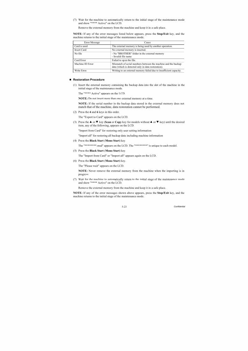
8/15/2019 Brother MFC 6510dw Sm
http://slidepdf.com/reader/full/brother-mfc-6510dw-sm 329/392
5-23 Confidential
(7) Wait for the machine to automatically return to the initial stage of the maintenance modeand show "**** Active" on the LCD.
Remove the external memory from the machine and keep it in a safe place.
NOTE: If any of the error messages listed below appears, press the Stop/Exit key, and themachine returns to the initial stage of the maintenance mode.
Restoration Procedure
(1) Insert the external memory containing the backup data into the slot of the machine in theinitial stage of the maintenance mode.
The "**** Active" appears on the LCD.
NOTE: Do not insert more than one external memory at a time.
NOTE: If the serial number in the backup data stored in the external memory does notmatch that of the machine, data restoration cannot be performed.
(2) Press the 4 and 6 keys in this order.
The "Export to Card" appears on the LCD.(3) Press the or key (Scan or Copy key for models without or key) until the desired
item, any of the following, appears on the LCD.
"Import from Card" for restoring only user setting information
"Import all" for restoring all backup data including machine information
(4) Press the Black Start (Mono Start) key.
The "********.msd" appears on the LCD. The "********" is unique to each model.
(5) Press the Black Start (Mono Start) key.
The "Import from Card" or "Import all" appears again on the LCD.
(6) Press the Black Start (Mono Start) key.
The "Please wait" appears on the LCD.
NOTE: Never remove the external memory from the machine when the importing is in progress.
(7) Wait for the machine to automatically return to the initial stage of the maintenance modeand show "**** Active" on the LCD.
Remove the external memory from the machine and keep it in a safe place.
NOTE: If any of the error messages shown above appears, press the Stop/Exit key, and the
machine returns to the initial stage of the maintenance mode.
Error Message Cause
Card is used The external memory is being used by another operation.
Insert Card No external memory is inserted.
No file - No "BROTHER" folder in the external memory- Invalid file name
Card Error Failed to open the file.
Machine ID Error Mismatch of serial numbers between the machine and the backupdata (which is detected only in data restoration).
Write Error Writing to an external memory failed due to insufficient capacity.
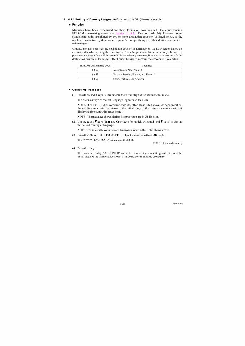
8/15/2019 Brother MFC 6510dw Sm
http://slidepdf.com/reader/full/brother-mfc-6510dw-sm 330/392
5-24 Confidential
5.1.4.12 Setting of Country/Language (Function code 52) (User-accessible)
Function
Machines have been customized for their destination countries with the correspondingEEPROM customizing codes (see Section 5.1.4.25, Function code 74). However, somecustomizing codes are shared by two or more destination countries as listed below, so themachines customized by these codes require further specifying individual destination countriesor languages.
Usually, the user specifies the destination country or language on the LCD screen called upautomatically when turning the machine on first after purchase. In the same way, the service personnel also specifies it if the main PCB is replaced; however, if he/she does not specify thedestination country or language at that timing, be sure to perform the procedure given below.
Operating Procedure
(1) Press the 5 and 2 keys in this order in the initial stage of the maintenance mode.
The "Set Country" or "Select Language" appears on the LCD.
NOTE: If an EEPROM customizing code other than those listed above has been specified,the machine automatically returns to the initial stage of the maintenance mode withoutdisplaying the country/language menu.
NOTE: The messages shown during this procedure are in US English.
(2) Use the and keys (Scan and Copy keys for models without and keys) to displaythe desired country or language.
NOTE: For selectable countries and languages, refer to the tables shown above.
(3) Press the OK key (PHOTO CAPTURE key for models without OK key).
The "*****? 1.Yes 2.No." appears on the LCD.***** : Selected country
(4) Press the 1 key.
The machine displays "ACCEPTED" on the LCD, saves the new setting, and returns to theinitial stage of the maintenance mode. This completes the setting procedure.
EEPROM Customizing Code Countries
**56 Australia and New Zealand
**57 Norway, Sweden, Finland, and Denmark
**65 Spain, Portugal, and Andorra
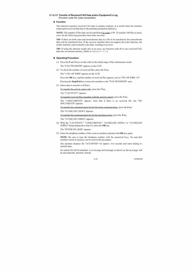
8/15/2019 Brother MFC 6510dw Sm
http://slidepdf.com/reader/full/brother-mfc-6510dw-sm 331/392
5-25 Confidential
5.1.4.13 Transfer of Received FAX Data and/or Equipment's Log
(Function code 53) (User-accessible)
Function
This function transfers received FAX data to another machine. It is useful when the machinecannot print received data due to the printing mechanism defective.
NOTE: The number of files that can be transferred at a time is 99. To transfer 100 files or more,carry out the following procedure more than one time.
TIP: If there are both color and monochrome data in a file to be transferred, the monochromedata will be transferred first. If the receiver machine does not support the color function, thesender machine cannot transfer color data, resulting in an error.
TIP: If using this function results also in an error, use Function code 46 to save received FAXdata into an external memory. (Refer to Section 5.1.4.11.)
Operating Procedure
(1) Press the 5 and 3 keys in this order in the initial stage of the maintenance mode.
The "FAX TRANSFER" appears on the LCD.
(2) To check the number of received files, press the 1 key.
The "1.NO. OF JOBS" appears on the LCD.
Press the OK key, and the number of received files appears, just as "NO. OF JOBS: 10."
Pressing the Stop/Exit key returns the machine to the "FAX TRANSFER" state.
(3) Select data to transfer as follows.
To transfer the activity report only, press the 2 key.
The "2.ACTIVITY" appears.
To transfer received files (together with the activity report), press the 3 key.
The "3.DOCUMENTS" appears. Note that if there is no received file, the "NODOCUMENTS" appears.
To transfer the communication list for the latest communication, press the 4 key.
The "4.COM.LIST (NEW)" appears.
To transfer the communication list for the last three errors, press the 5 key.
The "5.COM.LIST (ERR3)" appears.
(4) With the "2.ACTIVITY," "3.DOCUMENTS," "4.COM.LIST (NEW)," or "5.COM.LIST(ERR3)" being displayed in step (3), press the OK key.
The "ENTER NO. &OK" appears.
(5) Enter the telephone number of the receiver machine and press the OK key again.
NOTE: Be sure to type the telephone number with the numerical keys. No auto-dialnumbers stored in memory can be used in this procedure.
The machine displays the "ACCEPTED" for approx. two seconds and starts dialing totransfer data.
No station ID will be attached. A cover page and end page as shown on the next page will be automatically attached, instead.
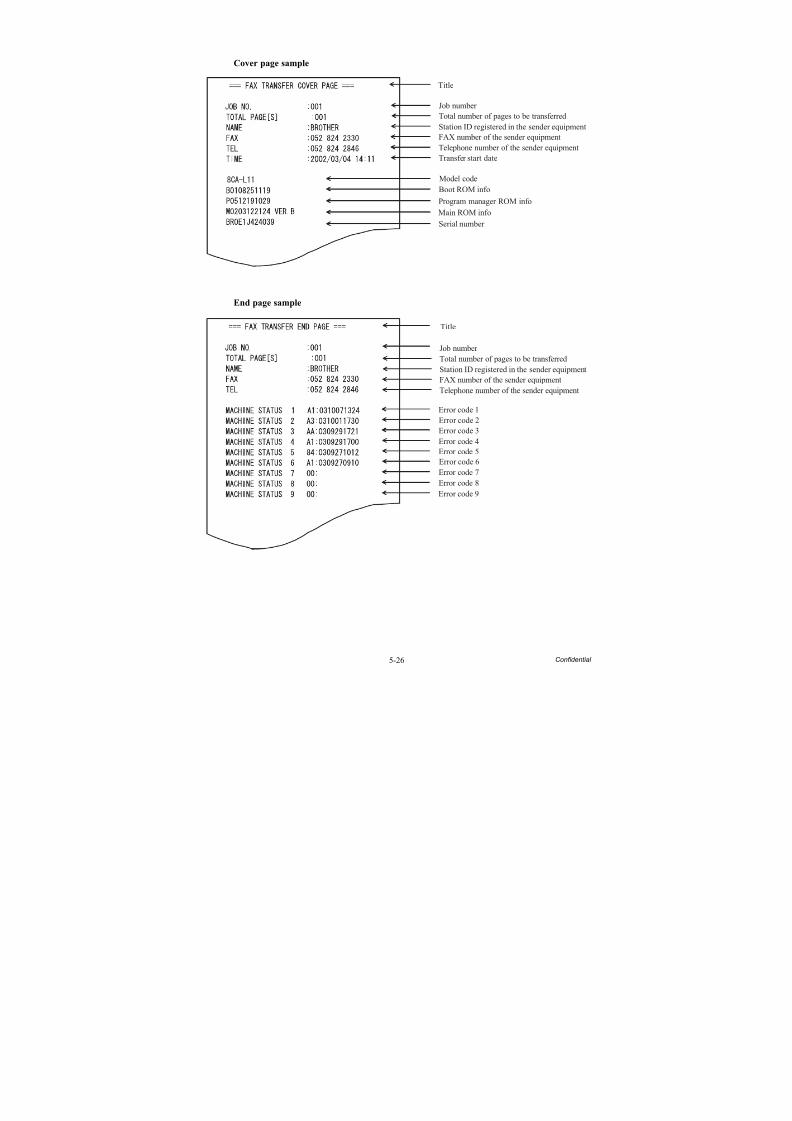
8/15/2019 Brother MFC 6510dw Sm
http://slidepdf.com/reader/full/brother-mfc-6510dw-sm 332/392
5-26 Confidential
Cover page sample
End page sample
Main ROM info
Serial number
Program manager ROM info
Boot ROM info
Model code
Transfer start date
Title
Total number of pages to be transferred
Job number
Station ID registered in the sender equipmentFAX number of the sender equipment
Telephone number of the sender equipment
Error code 1
Error code 2
Error code 3
Error code 4
Error code 5
Error code 6
Error code 7
Error code 8
Error code 9
Title
Total number of pages to be transferred
Job number
Station ID registered in the sender equipment
FAX number of the sender equipment
Telephone number of the sender equipment
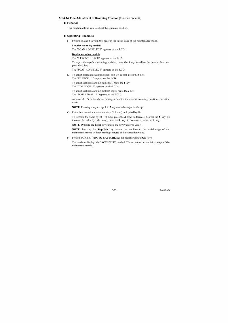
8/15/2019 Brother MFC 6510dw Sm
http://slidepdf.com/reader/full/brother-mfc-6510dw-sm 333/392
5-27 Confidential
5.1.4.14 Fine Adjustment of Scanning Position (Function code 54)
Function
This function allows you to adjust the scanning position.
Operating Procedure
(1) Press the 5 and 4 keys in this order in the initial stage of the maintenance mode.
Simplex scanning models
The "SCAN ADJ SELECT" appears on the LCD.
Duplex scanning models
The "0:FRONT 1:BACK" appears on the LCD.
To adjust the top-face scanning position, press the 0 key; to adjust the bottom-face one, press the 1 key.
The "SCAN ADJ SELECT" appears on the LCD.
(2) To adjust horizontal scanning (right and left edges), press the 0 key.
The "RL EDGE *" appears on the LCD.
To adjust vertical scanning (top edge), press the 1 key.
The "TOP EDGE *" appears on the LCD.
To adjust vertical scanning (bottom edge), press the 2 key.
The "BOTM EDGE *" appears on the LCD.
An asterisk (*) in the above messages denotes the current scanning position correctionvalue.
NOTE: Pressing a key except 0 to 2 keys sounds a rejection beep.
(3) Enter the correction value (in units of 0.1 mm) multiplied by 10.
To increase the value by 10 (1.0 mm), press the key; to decrease it, press the key. Toincrease the value by 1 (0.1 mm), press the key; to decrease it, press the key.
NOTE: Pressing the Clear key cancels the newly entered value.
NOTE: Pressing the Stop/Exit key returns the machine to the initial stage of themaintenance mode without making changes of the correction value.
(4) Press the OK key (PHOTO CAPTURE key for models without OK key).
The machine displays the "ACCEPTED" on the LCD and returns to the initial stage of the
maintenance mode.

8/15/2019 Brother MFC 6510dw Sm
http://slidepdf.com/reader/full/brother-mfc-6510dw-sm 334/392
5-28 Confidential
5.1.4.15 Acquisition of White Level Data and CIS Scanner Area Setting
(Function code 55)
Function
This procedure allows the machine to obtain white level data for the CIS scanner and save ittogether with the CIS scanner area into the EEPROM on the main PCB.
The duplex scanning model obtains also white level data for the second side scanning CIS.
Operating Procedure
(1) Press the 5 key twice in the initial stage of the maintenance mode.
The "SCANNER AREA SET" appears on the LCD.
The machine automatically obtains white level data.
(2) If this operation completes normally, the machine returns to the initial stage of themaintenance mode.
If any error is detected, the "SCANNER ERROR" appears on the LCD. To return themachine to the initial stage of the maintenance mode, press the Stop/Exit key.
8/15/2019 Brother MFC 6510dw Sm
http://slidepdf.com/reader/full/brother-mfc-6510dw-sm 335/392
5-29 Confidential
5.1.4.16 Updating of Paper Feeding Correction Value (Function code 58)
Function
To match the paper feeding amount with the head nozzle pitch, the machine optimizes therotations of the paper feed roller and paper ejection roller, using the correction value stored inthe EEPROM on the main PCB.
If you replace the engine unit or head/carriage unit, you need to update the paper feedingcorrection value according to the procedure given here.
Operating Procedure
Before starting the procedure below, be sure to set letter-size paper in the paper tray for
printing check patterns
For the paper feed roller adjustment using paper tray #1
(1) On your PC, drag and drop the "pf_midadj.prn" onto the Brother Maintenance USB Printer
driver icon in the Filedrgs window.The machine displays the "RECEIVING DATA" on the LCD and prints out "PF-EXITadjust check" pattern on paper fed from paper tray #1 (see page 5-31 for a sample printout).
Tip: Using Function code 61 (Section 5.1.4.18 "Printout of PRN/JPEG Files in MemoryCard (Function code 61)") also prints out the check pattern. After printing with a memorycard, be sure to remove the card and then proceed to the steps below.
(2) On the machine, press the 5 and 8 keys in this order.
The "Select 58?" appears on the LCD.
(3) Press the Black Start (Mono Start) key.
The "1.PF 2.EXIT 3.MID" appears on the LCD.
(4) To select the paper feed roller adjustment using paper tray #1, press the 1 key.
The "PF1 ADJ NO. +0" appears on the LCD.
(5) On the "PF-EXIT adjust check" pattern printed in step (1) (see page 5-31), check each of PF1 through PF6 rows sequentially. First, on PF1 row, select the block that is the leastuneven print and enter the number of the least uneven block.
For example, if the number of the least uneven block is +4, press the 4 key while the "PF1ADJ NO. +0" is displayed on the LCD. If the number is -4, press the key to display the"PF1 ADJ NO. -0" and press the 4 key.
Then press the OK key.
(6) In the same way as in step (5), enter the number of the least uneven block for each of PF2through PF7.
For the paper ejection roller adjustment
(1) On your PC, drag and drop the "exitadj1.prn" onto the Brother Maintenance USB Printer driver icon in the Filedrgs window.
The machine displays the "RECEIVING DATA" on the LCD and prints out "EXIT adjustcheck" pattern 1 (see page 5-32 for a sample printout).
In the same way, use the "exitadj2.prn" and "exitadj3.prn" to print out "EXIT adjust check" patterns 2 and 3, respectively (see pages 5-33 and 5-34 for sample printouts).
(2) On the machine, press the 5 and 8 keys in this order.
The "Select 58?" appears on the LCD.
8/15/2019 Brother MFC 6510dw Sm
http://slidepdf.com/reader/full/brother-mfc-6510dw-sm 336/392
5-30 Confidential
(3) Press the Black Start (Mono Start) key.
The "1.PF 2.EXIT 3.MID" appears on the LCD.
(4) To select the paper ejection roller adjustment, press the 2 key.
The "EXIT ADJ NO. +0" appears on the LCD.
(5) On the "EXIT adjust check" patterns 1 to 3 (see pages 5-32 through 5-34), check EXIT1through EXIT6 rows.
First, on the EXIT1 row, select the block that is the least uneven print and enter the number of the least uneven block. For the entry method, refer to the paper feed roller adjustment procedure, step (5).
(6) In the same way as in step (5), enter the number of the least uneven block for each of EXIT2 through EXIT6.
For the intermediate roller adjustment
(1) On the machine, press the 5 and 8 keys in this order.
The "Select 58?" appears on the LCD.(2) Press the Black Start (Mono Start) key.
The "1.PF 2.EXIT 3.MID" appears on the LCD.
(3) To select the intermediate roller adjustment, press the 3 key.
The "MID ADJ NO. +0" appears on the LCD.
(4) On the "PF-EXIT adjust check" pattern (see page 5-31), check the MID row. Select the block that is the least uneven print and enter the number of the least uneven block. For theentry method, refer to the paper feed roller adjustment procedure, step (5).
For adjustment of horizontal streaks
(1) On your PC, drag and drop the "LF300adj.prn" onto the Brother Maintenance USB Printer driver icon in the Filedrgs window.
The machine displays the "RECEIVING DATA" on the LCD and prints out "KEISEN2 &LF300 & EXIT ADJUST PATTERN" (see page 5-35 for a sample printout).
Tip: Using Function code 61 (Section 5.1.4.18 "Printout of PRN/JPEG Files in MemoryCard (Function code 61)") also prints out the check pattern. After printing with a memorycard, be sure to remove the card and then proceed to the steps below.
(2) On the machine, press the 5 and 8 keys in this order.
The "Select 58?" appears on the LCD.
(3) Press the Black Start (Mono Start) key.The "1.PF 2.EXIT 3.MID" appears on the LCD.
(4) Press the key several times to display the "1.LF300" on the LCD.
(5) Press the 1 key to display the "LF300 ADJ No. +0."
(6) Check the LF300 ADJUST pattern (see page 5-35), select the block that has the least whiteand black streaks, and enter the number of that block. For the entry method, refer to the paper feed roller adjustment procedure, step (5).

8/15/2019 Brother MFC 6510dw Sm
http://slidepdf.com/reader/full/brother-mfc-6510dw-sm 337/392
5-31 Confidential
PF-EXIT Adjust Check Pattern
Paper feed rolleradjustment
Intermediateroller adjustment
Paper ejectionroller adjustment

8/15/2019 Brother MFC 6510dw Sm
http://slidepdf.com/reader/full/brother-mfc-6510dw-sm 338/392
5-32 Confidential
EXIT Adjust Check Pattern 1
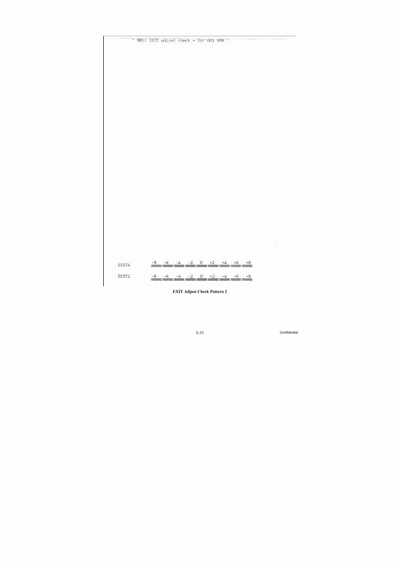
8/15/2019 Brother MFC 6510dw Sm
http://slidepdf.com/reader/full/brother-mfc-6510dw-sm 339/392
5-33 Confidential
EXIT Adjust Check Pattern 2
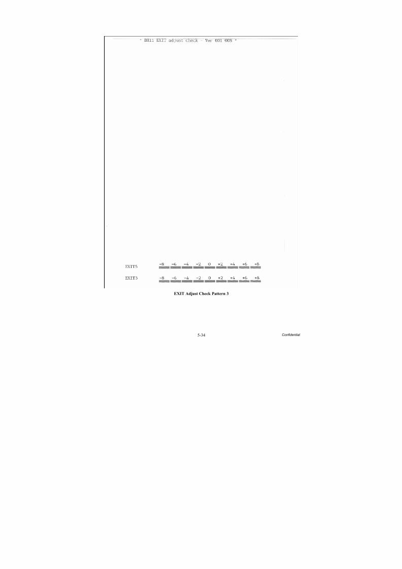
8/15/2019 Brother MFC 6510dw Sm
http://slidepdf.com/reader/full/brother-mfc-6510dw-sm 340/392
5-34 Confidential
EXIT Adjust Check Pattern 3
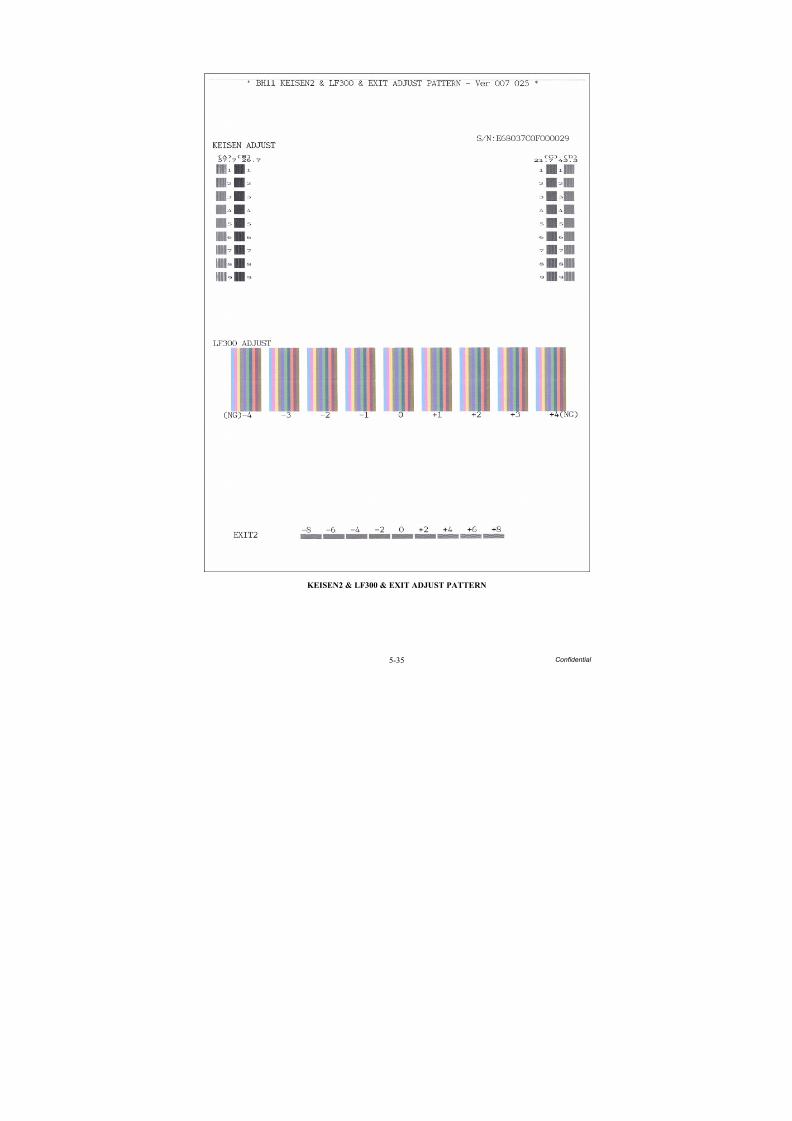
8/15/2019 Brother MFC 6510dw Sm
http://slidepdf.com/reader/full/brother-mfc-6510dw-sm 341/392
5-35 Confidential
KEISEN2 & LF300 & EXIT ADJUST PATTERN
8/15/2019 Brother MFC 6510dw Sm
http://slidepdf.com/reader/full/brother-mfc-6510dw-sm 342/392
5-36 Confidential
5.1.4.17 Checking of CIS Travel (Function code 59)
Function
This procedure allows you to check the movement of the CIS unit integrated in the scanner cover (scanner unit). The CIS unit travels to the three positions--the white reference film position, scanning start and end positions.
Operating Procedure
-- Check the movement of the CIS unit --
(1) Press the 5 and 9 keys in this order in the initial stage of the maintenance mode.
Simplex scanning models
The "1:MONO 2:COLOR?" appears on the LCD.
Duplex scanning models
The "CIS 1:FB 2:ADF" appears on the LCD.
Press the 1 key to display "1: MONO 2:COLOR?"(2) To call up the CIS travel menu, press the 1 key.
(The "2:COLOR" is for checking scanning clocks at the factory, so do not access it.)
The "RESO TYPE SET 1" appears on the LCD.
(3) Press the OK key (PHOTO CAPTURE key for models without OK key).
The "LED PWM : **" appears on the LCD.
(4) Press the OK key (PHOTO CAPTURE key for models without OK key).
The "G PULSE : ****" appears on the LCD.
(5) Press the OK key (PHOTO CAPTURE key for models without OK key).
The "1:WHT 2:FRT 3:MV" appears.
(6) Press the 3, 1, or 2 key, then press the OK key (PHOTO CAPTURE key for modelswithout OK key).
The CIS unit moves to the scanning end position, white reference film position, or scanningstart position, respectively.
(7) Press the Stop/Exit key, and the CIS unit returns to the home position.
The machine returns to the initial stage of the maintenance mode.
8/15/2019 Brother MFC 6510dw Sm
http://slidepdf.com/reader/full/brother-mfc-6510dw-sm 343/392
5-37 Confidential
5.1.4.18 Printout of PRN/JPEG Files in Memory Card (Function code 61)
Function
This procedure prints PRN files and JPEG files stored in a memory card supported byPhotoCapture Center.
The following three print modes are available.- Printing the specified file only once
- Printing all files repeatedly (PRN files and JPEG files stored in a memory card)
- Printing the specified file repeatedly
File requirements
PRN files having the name "file_**.prn"JPEG files having the name "file_**.jpg"
(** should be a numeral ranging from 01 to 63. Other file names will be ignored.)
The maximum number of files is 63.
Operating Procedure
-- Printing the specified file only once --
(1) Press the 6 and 1 keys in this order in the initial stage of the maintenance mode.
The "MAINTENANCE 61" appears on the LCD.
(2) To print a PRN file, press the # key; to print a JPEG file, press the * key. Then enter thenumeral (two digits from 01 to 63) in the file name to be printed in succession, using thenumerical keys.
The machine prints the specified file once.
(3) Upon completion of printing, the machine goes back to step (2).Printing the Stop key halfway through printing immediately stops printing and returns themachine to the initial stage of the maintenance mode.
-- Printing all files repeatedly --
(1) Press the 6 and 1 keys in this order in the initial stage of the maintenance mode.
The "MAINTENANCE 61" appears on the LCD.
(2) To print PRN files, press the #, 0 and 0 keys; to print JPEG files, press the *, 0 and 0 keysin this order.
The machine prints files, starting from the first one. After printing of all files, it repeats printing from the first file.
(3) To stop printing PRN files, press the #, 9 and 9 keys; to stop printing JPEG files, press the*, 9 and 9 keys in this order.
After completion of printing of the current file, the machine stops repeated printing.
Printing the Stop key halfway through printing immediately stops printing and returns themachine to the initial stage of the maintenance mode.

8/15/2019 Brother MFC 6510dw Sm
http://slidepdf.com/reader/full/brother-mfc-6510dw-sm 344/392
5-38 Confidential
-- Printing the specified file repeatedly --
(1) Press the 6 and 1 keys in this order in the initial stage of the maintenance mode.
The "MAINTENANCE 61" appears on the LCD.
(2) To print a PRN file, press the #, 9, 8 and # keys in this order; to print a JPEG file, press the
*, 9, 8 and * keys in this order. Then enter the numeral (two digits from 01 to 63) in the filename to be printed in succession, using the numerical keys.
The machine prints the specified file repeatedly.
(3) To stop printing PRN files, press the #, 9 and 9 keys; to stop printing JPEG files, press the*, 9 and 9 keys in this order.
After completion of the current printing, the machine stops repeated printing.
Printing the Stop key halfway through printing immediately stops printing and returns themachine to the initial stage of the maintenance mode.
8/15/2019 Brother MFC 6510dw Sm
http://slidepdf.com/reader/full/brother-mfc-6510dw-sm 345/392
5-39 Confidential
5.1.4.19 Travel Check of the Head/Carriage Unit and Initial Setup Mode
(Function code 63)
Function
This procedure moves the head/carriage unit to the center of its travel (Function code 63 + *).
It can also enable or disable the initial setup mode when the power is applied at the next time(Function code 63 + 1 or Function code 63 +3).
The initial setup mode refers to a mode in which the machine performs an initial purgeautomatically when the power is turned on.
Operating Procedure
(1) Press the 6 and 3 keys in this order in the initial stage of the maintenance mode.
The "SELECT 63?" appears on the LCD.
(2) Press the Black Start (Mono Start) key.
The "START 63" appears on the LCD.
(3) To make the head/carriage unit travel to the center of its travel, press the * key.
The "HEAD ADJ" appears on the LCD.
After completion of head replacement or adjustment jobs, press the Stop/Exit key. Thehead/carriage unit returns to the home position and then locks itself.
(4) To enable or disable the initial setup mode when the power is applied at the next time, perform steps (1) and (2) again and then press the 1 or 3 key, respectively.
If you enable the initial setup mode, wait until the "INIT" appears on the LCD and thehead/carriage unit becomes locked. When the "HEAD LOCKED" appears, turn the power off.
NOTE: Enabling the initial setup mode resets all counts which can be displayed withFunction code 80 (described in Section 5.1.4.30 "Display of the Equipment's Log (Functioncode 80) (User-accessible)").
If you disable the initial setup mode, the machine displays the "NOT INIT" on the LCDand returns to the initial stage of the maintenance mode.
8/15/2019 Brother MFC 6510dw Sm
http://slidepdf.com/reader/full/brother-mfc-6510dw-sm 346/392
5-40 Confidential
5.1.4.20 Alignment of Vertical Print Lines in Monochrome (Function code 65)
Function
This procedure aligns vertical lines printed in the forward and backward directions of the head/carriage unit.
If the head/carriage unit, main PCB, engine unit, or carriage motor is replaced, you need tomake the adjustment given in this section.
Note: If the head/carriage unit or the engine unit is replaced, you need to make other adjustments in addition, referring to Chapter 4, Section 4.1 [ 4 ].
Operating Procedure
Before starting the procedure below, be sure to set letter-size or A4-size paper in the paper tray
for printing check patterns.
(1) Press the 6 and 5 keys in this order in the initial stage of the maintenance mode. Then press
the 1 key in succession.The machine displays the "PRINTING" on the LCD and prints the vertical alignment check pattern of A to D rows (see the next page for a sample printout). Each of A to D rowsconsists of #1 through #9 blocks.
If the vertical alignment is ON, #5 block in each of A to D rows shows vertically alignedlines.
The "A No. (1-9)" appears on the LCD.
(2) Check the A row, find which number block shows full alignment and enter that block number.
The "B No. (1-9)" appears on the LCD.
(3) Check the B row, find which number block shows full alignment and enter that block number.
The "C No. (1-9)" appears on the LCD.
(4) In the same way, enter the block number of full alignment for the C and D rows.
The machine automatically returns to the initial stage of the maintenance mode.
Note: If #1 or #9 block is fully aligned so that you press the 1 or 9 key in the above procedure,the machine shows "PRINTING" on the LCD and prints the vertical alignment check patternagain. Go back to step (2) and make adjustments again.

8/15/2019 Brother MFC 6510dw Sm
http://slidepdf.com/reader/full/brother-mfc-6510dw-sm 347/392
5-41 Confidential
Vertical Alignment Check Pattern
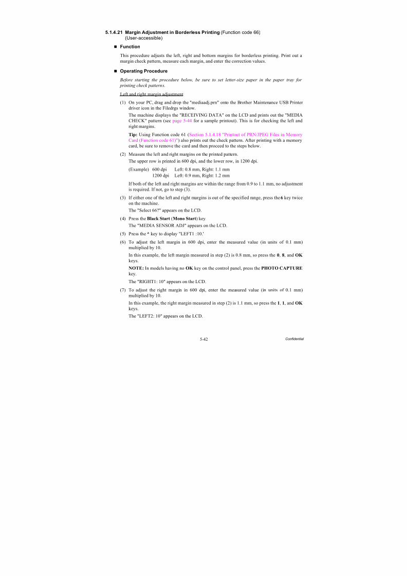
8/15/2019 Brother MFC 6510dw Sm
http://slidepdf.com/reader/full/brother-mfc-6510dw-sm 348/392
5-42 Confidential
5.1.4.21 Margin Adjustment in Borderless Printing(Function code 66)
(User-accessible)
Function
This procedure adjusts the left, right and bottom margins for borderless printing. Print out amargin check pattern, measure each margin, and enter the correction values.
Operating Procedure
Before starting the procedure below, be sure to set letter-size paper in the paper tray for
printing check patterns.
Left and right margin adjustment
(1) On your PC, drag and drop the "mediaadj.prn" onto the Brother Maintenance USB Printer driver icon in the Filedrgs window.
The machine displays the "RECEIVING DATA" on the LCD and prints out the "MEDIACHECK" pattern (see page 5-44 for a sample printout). This is for checking the left andright margins.
Tip: Using Function code 61 (Section 5.1.4.18 "Printout of PRN/JPEG Files in MemoryCard (Function code 61)") also prints out the check pattern. After printing with a memorycard, be sure to remove the card and then proceed to the steps below.
(2) Measure the left and right margins on the printed pattern.
The upper row is printed in 600 dpi, and the lower row, in 1200 dpi.
(Example) 600 dpi Left: 0.8 mm, Right: 1.1 mm1200 dpi Left: 0.9 mm, Right: 1.2 mm
If both of the left and right margins are within the range from 0.9 to 1.1 mm, no adjustmentis required. If not, go to step (3).
(3) If either one of the left and right margins is out of the specified range, press the 6 key twiceon the machine.
The "Select 66?" appears on the LCD.
(4) Press the Black Start (Mono Start) key.
The "MEDIA SENSOR ADJ" appears on the LCD.
(5) Press the * key to display "LEFT1 :10."
(6) To adjust the left margin in 600 dpi, enter the measured value (in units of 0.1 mm)multiplied by 10.
In this example, the left margin measured in step (2) is 0.8 mm, so press the 0, 8, and OK
keys.
NOTE: In models having no OK key on the control panel, press the PHOTO CAPTURE
key.
The "RIGHT1: 10" appears on the LCD.
(7) To adjust the right margin in 600 dpi, enter the measured value (in units of 0.1 mm)multiplied by 10.
In this example, the right margin measured in step (2) is 1.1 mm, so press the 1, 1, and OK
keys.
The "LEFT2: 10" appears on the LCD.
8/15/2019 Brother MFC 6510dw Sm
http://slidepdf.com/reader/full/brother-mfc-6510dw-sm 349/392
5-43 Confidential
(8) To adjust the left margin in 1200 dpi, enter the measured value (in units of 0.1 mm)multiplied by 10.
In this example, the right margin measured in step (2) is 0.9 mm, so press the 0, 9, and OK
keys.
The "RIGHT2: 10" appears on the LCD.
(9) To adjust the right margin in 1200 dpi, enter the measured value (in units of 0.1 mm)multiplied by 10.
In this example, the right margin measured in step (2) is 1.2 mm, so press the 1, 2, and OK
keys.
Upon completion of the entry, the machine automatically returns to the initial stage of themaintenance mode.
(10)Go back to step (1) and print out the left and right margin check pattern again.
(11)Measure the left and right margins on the printed pattern.
If both of the left and right margins are within the range from 0.9 to 1.1 mm, the adjustmentis completed.
Bottom margin adjustment
(1) Measure the bottom margin on the "MEDIA CHECK" pattern printed in the left and rightmargin adjustment procedure, step (1) above.
(Example) Bottom margin: 3.2 mm
If it is within the range from 2.9 to 3.1 mm, no adjustment is required. If not, go to step (2).
(2) If the bottom margin is out of the specified range, press the 6 key twice on the machine.
(3) Press the Black Start (Mono Start) key.
The "MEDIA SENSOR ADJ" appears on the LCD.
(4) Press the # key to display "BOTTOM :30."
(5) To adjust the bottom margin, enter the measured value (in units of 0.1 mm) multiplied by10.
In this example, the bottom margin measured in step (1) is 3.2 mm, so press the 3, 2, andOK keys.
Upon completion of the entry, the machine automatically returns to the initial stage of themaintenance mode.
(6) Go back to step (1) and print out the check pattern again.
(7) Measure the bottom margin on the printed pattern.
If it is within the range from 2.9 to 3.1 mm, the adjustment is completed.
Note: To reset the correction values newly entered in the above procedure, press the 6, 6, Start,8, 9, 5 and 4 keys in this order in the initial stage of the maintenance mode. The machine shows"PARAMETER INIT" on the LCD and returns to the initial stage of the maintenance mode.
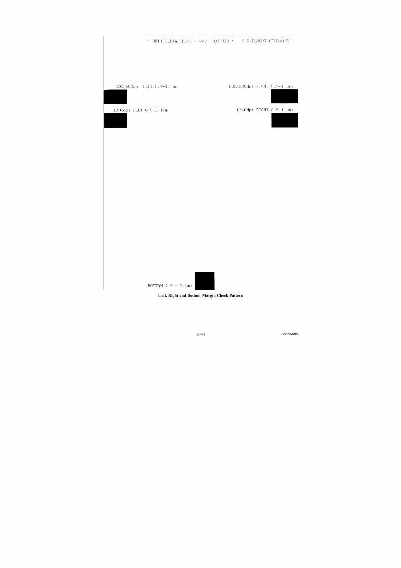
8/15/2019 Brother MFC 6510dw Sm
http://slidepdf.com/reader/full/brother-mfc-6510dw-sm 350/392
5-44 Confidential
Left, Right and Bottom Margin Check Pattern
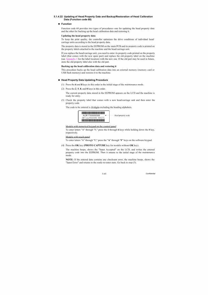
8/15/2019 Brother MFC 6510dw Sm
http://slidepdf.com/reader/full/brother-mfc-6510dw-sm 351/392
5-45 Confidential
5.1.4.22 Updating of Head Property Data and Backup/Restoration of Head Calibration
Data (Function code 68)
Function
Function code 68 provides two types of procedures--one for updating the head property dataand the other for backing up the head calibration data and restoring it.
Updating the head property data
To keep the print quality, the controller optimizes the drive conditions of individual head/carriage units according to the head property data.
The property data is stored in the EEPROM on the main PCB and its property code is printed onthe property labels attached to the machine and the head/carriage unit.
If you replace the head/carriage unit, you need to enter its property code printed on the propertylabel (that comes with the new spare part) and replace the old property label on the machine(see Appendix 1 for the label location) with the new one. If the old part may be used in future,store the old property label also with the old part.
Backing up the head calibration data and restoring it
This procedure backs up the head calibration data into an external memory (memory card or USB flash memory) and restores it to the machine.
Head Property Data Updating Procedure
(1) Press the 6 and 8 keys in this order in the initial stage of the maintenance mode.
(2) Press the 2, 5, 8, and 0 keys in this order.
The current property data stored in the EEPROM appears on the LCD and the machine isready for entry.
(3) Check the property label that comes with a new head/carriage unit and then enter the property code.
The code to be entered is 10 digits excluding the heading alphabets.
Models with numerical keypad on the control panel
To enter letters "A" through "F," press the 1 through 6 keys while holding down the # key,
respectively.
Models with touch panel
To enter letters "A" through "F," press the "A" through "F" keys on the software keypad.
(4) Press the OK key (PHOTO CAPTURE key for models without OK key).
The machine beeps, shows the "Input Accepted" on the LCD, and writes the entered property code into the EEPROM. Then it returns to the initial stage of the maintenancemode.
NOTE: If the entered data contains any checksum error, the machine beeps, shows the"Input Error" and returns to the ready-to-enter state. Go back to step (3).
8/15/2019 Brother MFC 6510dw Sm
http://slidepdf.com/reader/full/brother-mfc-6510dw-sm 352/392
5-46 Confidential
Head Calibration Data Backup/Restoration Procedures
Backup procedure
(1) Press the 6 and 8 keys in this order in the initial stage of the maintenance mode.
(2) Press the 0, 6, 2, and 6 keys in this order.
The "Write Head Calib" appears on the LCD.
(3) Insert an external memory into the memory slot.
(4) Use the and keys to display "Head Calib->Media" on the LCD and then press the OK
key.
The machine displays "Now Saving" on the LCD and starts the backup operation.
Note: If no external memory is inserted into the memory slot in step (3), the machinesounds a short beep three times and displays "No Media Error" on the LCD.
Upon completion of the backup operation, the machine beeps for one second, displays"Head Calib.data" on the LCD, and then returns to the initial stage of the maintenance
mode.
Restoration procedure
(1) Press the 6 and 8 keys in this order in the initial stage of the maintenance mode.
(2) Press the 0, 6, 2, and 6 keys in this order.
The "Write Head Calib" appears on the LCD.
(3) Insert the external memory holding the head property data into the memory slot.
(4) Use the and keys to display "Media->Head Calib" on the LCD and then press the OK
key.The machine displays "Now Loading" on the LCD and starts the restoration operation.
Note: If no external memory is inserted into the memory slot in step (3), the machinesounds a short beep three times and displays "No Media Error" on the LCD.
Note: If the external memory inserted in step (3) holds no head calibration data, the "Can’tOpen File" appears on the LCD.
Upon completion of the restoration operation, the machine beeps for one second, displays"Complete" on the LCD, and then returns to the initial stage of the maintenance mode.

8/15/2019 Brother MFC 6510dw Sm
http://slidepdf.com/reader/full/brother-mfc-6510dw-sm 353/392
5-47 Confidential
5.1.4.23 Traveling Speed Check of Head/Carriage Unit(Function code 69)
Function
This procedure checks whether the head/carriage unit travels within the specified range.
If you replace the head/carriage unit, carriage motor or CR encoder strip, loosen the CR timing
belt, or apply lubricant, be sure to perform this procedure.
Operating Procedure
(1) Press the 6 and 9 keys in this order in the initial stage of the maintenance mode.
The machine shows "CR AGING" on the LCD and starts aging of the head/carriage unit.
In each of travel speeds of 57.7, 43.3, 26.7 and 21.7 inches/second (ips), the machinechecks whether the maximum and minimum traveling speeds of the head/carriage unit arewithin the specified range.
- If the maximum and minimum speeds in all of the four traveling speeds are within the
specified range, the "57O 43O 27O 21O" appears on the LCD- If any one is out of the range, the machine shows some message, e.g., "57O 43O 27O
21X" on the LCD. This sample message indicates that the speed variation is within theallowable range when the head/carriage unit travels at 57.7, 43.3 and 26.7 inches/second; however, it is out of the range at 21.7 inches/second.
(2) Press the Stop/Exit key to return the machine to the initial stage of the maintenance mode.
8/15/2019 Brother MFC 6510dw Sm
http://slidepdf.com/reader/full/brother-mfc-6510dw-sm 354/392
5-48 Confidential
5.1.4.24 Cleaning of Leveler Roller (LR) ASSY(Function code 70)
Function
This procedure clears ink sticking to the leveler roller (LR) ASSY.
Operating Procedure
(1) Fold a sheet of A4- or letter-size recording paper in half in a longitudinal direction, unfoldit, set it in the empty paper tray #1 with the valley fold facing up as shown below.
(2) Press the 7 and 0 keys in this order in the initial stage of the maintenance mode.
The "1.A4 2.LTR" appears on the LCD.
(3) To use an A4-size paper, press the 1 key; to use a letter-size one, use the 2 key.
The machine shows "LRS CLEANING" on the LCD and starts cleaning the leveler roller (LR) ASSY.
(4) Wait for the cleaning to complete (it takes approximately four minutes) and for the "PUSH
STOP KEY" to appear on the LCD.(5) Press the Stop/Exit key.
The machine ejects the recording paper and returns to the initial stage of the maintenancemode.
(3_012a)
Leveler roller (LR)ASSY
Valley fold

8/15/2019 Brother MFC 6510dw Sm
http://slidepdf.com/reader/full/brother-mfc-6510dw-sm 355/392
5-49 Confidential
5.1.4.25 EEPROM Customizing (Function code 74)
Function
This procedure customizes the EEPROM according to language, function settings, andfirmware switch settings.
NOTES: • If you replace the main PCB, be sure to carry out this procedure.• Once this procedure is carried out, it is necessary to write the corresponding
language data, so be sure to write local programs, referring to Chapter 4, Section4.2 [ 4 ].
Operating Procedure
(1) Press the 7 and 4 keys in this order in the initial stage of the maintenance mode.
The "SELECT 74?" appears on the LCD.
(2) Press the Black Start (Mono Start) key, and the current customizing code appears.
(3) Enter the desired customizing code. (See the following pages.)
NOTE: If a wrong 4-digit code is entered, the machine will malfunction.
(4) Press the Black Start (Mono Start) key.
The machine saves the setting and returns to the initial stage of the maintenance mode.
If you press the Stop/Exit key or no keys are pressed for one minute in the above procedure, the machine stops the procedure and returns to the initial stage of themaintenance mode.
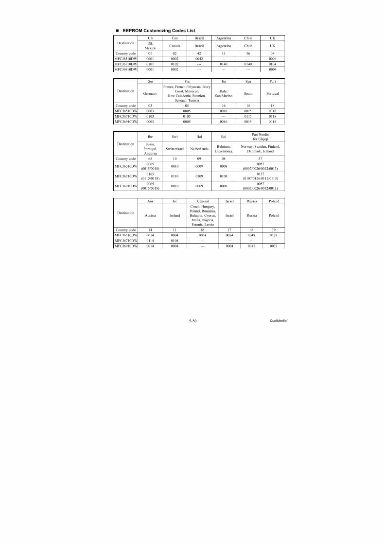
8/15/2019 Brother MFC 6510dw Sm
http://slidepdf.com/reader/full/brother-mfc-6510dw-sm 356/392
5-50 Confidential
EEPROM Customizing Codes List
Destination
US Can Brazil Argentina Chile UK
US,Mexico
Canada Brazil Argentina Chile UK
Country code 01 02 42 31 36 04
MFCJ6510DW 0001 0002 0042 --- --- 0004
MFCJ6710DW 0101 0102 --- 0140 0140 0104
MFCJ6910DW 0001 0002 --- --- --- 0004
Destination
Ger Fra Ita Spa Port
Germany
France, French Polynesia, IvoryCoast, Morocco,
New Caledonia, Reunion,Senegal, Tunisia
Italy,San Marino
Spain Portugal
Country code 03 05 16 15 18
MFCJ6510DW 0003 0005 0016 0015 0018
MFCJ6710DW 0103 0105 --- 0115 0118
MFCJ6910DW 0003 0005 0016 0015 0018
Destination
Ibe Swi Hol BelPan Nordicfor Elkjop
Spain,Portugal,Andorra
Switzerland NetherlandsBelgium,
Luxemburg Norway, Sweden, Finland,
Denmark, Iceland
Country code 65 10 09 08 57
MFCJ6510DW0065
(0015/0018)0010 0009 0008
0057(0007/0026/0012/0013)
MFCJ6710DW0165
(0115/0118)0110 0109 0108
0157(0107/0126/0112/0113)
MFCJ6910DW 0065(0015/0018)
0010 0009 0008 0057(0007/0026/0012/0013)
Destination
Aus Ire General Israel Russia Poland
Austria Ireland
Czech, Hungary,Poland, Rumania,Bulgaria, Cyprus,
Malta, Nigeria,Estonia, Latvia
Israel Russia Poland
Country code 14 11 88 17 48 39
MFCJ6510DW 0014 0004 0054 0054 0048 0039
MFCJ6710DW 0114 0104 --- --- --- ---
MFCJ6910DW 0014 0004 --- 0004 0048 0039

8/15/2019 Brother MFC 6510dw Sm
http://slidepdf.com/reader/full/brother-mfc-6510dw-sm 357/392
5-51 Confidential
The above information is as of September 2010. The up-to-date information is available from your local Brother Customer Service.
Destination
Sin/Gulf S. Africa Turkey HK Oceania
Singapore, Malaysia,Philippines, Indonesia,Vietnam, UAE, India
S. Africa Turkey Hong KongAustralia, New Zealand, Fiji,Papua New Guinea, Samoa,
Tonga
Country code 40 24 25 28 56
MFCJ6510DW 0040 0024 0054 00400056
(0006/0027)
MFCJ6710DW 0140 --- 0104 01280156
(0016/0127)
MFCJ6910DW 0040 --- 0004 ---0056
(0006/0027)
DestinationKorea Taiwan China
Korea Taiwan China
Country code 44 23 20
MFCJ6510DW --- --- ---
MFCJ6710DW 0144 0123 0120
MFCJ6910DW --- 0023 0020

8/15/2019 Brother MFC 6510dw Sm
http://slidepdf.com/reader/full/brother-mfc-6510dw-sm 358/392
5-52 Confidential
5.1.4.26 Travel of Head/Carriage Unit (for removing paper particles and dust
accumulated on the maintenance unit) (Function code 75)
(User-accessible)
Function
This function is used to remove paper particles and dust accumulated between the maintenanceunit and head/carriage unit. Using this function moves the head/carriage unit to the center of itstravel, allowing you to easily remove the paper particles and dust accumulated.
Operating Procedure
(1) Press the 7 and 5 keys in this order in the initial stage of the maintenance mode.
The "PLS OPEN COVER" appears on the LCD.
(2) Open the scanner cover.
The head/carriage unit moves to the center of its travel.
(3) Remove the paper particles and dust accumulated.(4) Close the scanner cover.
The head/carriage unit moves back to the home position and the machine returns to theinitial stage of the maintenance mode.
TIP: Holding down the Stop/Exit key with the scanner cover opened for more than fiveseconds can also move the head/carriage unit in the same manner as above.
8/15/2019 Brother MFC 6510dw Sm
http://slidepdf.com/reader/full/brother-mfc-6510dw-sm 359/392
5-53 Confidential
5.1.4.27 Purge Operation (Function code 76) (User-accessible)
Function
The machine can carry out several types of purge operations--normal purge, periodical reset purge, power purge, initial purge, user reset purge, and engine setup purge. This function allowsyou to select the desired purge type and carry it out.
TIP: The purge types and their details are described on the next page.
Operating Procedure
(1) Press the 7 and 6 keys in this order in the initial stage of the maintenance mode.
The machine displays the "CLEANING ALL" on the LCD and enters the purge mode.
(2) Press the and key to display the target color for purge.
NOTE: In models with touch panel, if the , , , and keys are not displayed on thesoftware keypad, it is necessary to switch the software keypads between the numerical and
function keypads by pressing the Scan and Copy keys simultaneously.Each time the or key is pressed, the "CLEANING ALL," "CLEANING BLACK,""CLEANING MAGENTA," "CLEANING CYAN," or "CLEANING YELLOW" appearscyclically.
"CLEANING ALL": Purge for all four color inks
"CLEANING BLACK": Purge for black ink
"CLEANING MAGENTA" / "CLEANING CYAN" / "CLEANING YELLOW": Any colorchoice performs purge for all three color inks.
(3) Enter the purge code according to the table on the next page.
(4) Press the Black Start (Mono Start) key.
The LCD displays "Cleaning."
Upon completion of purging, the machine automatically returns to the initial stage of themaintenance mode.
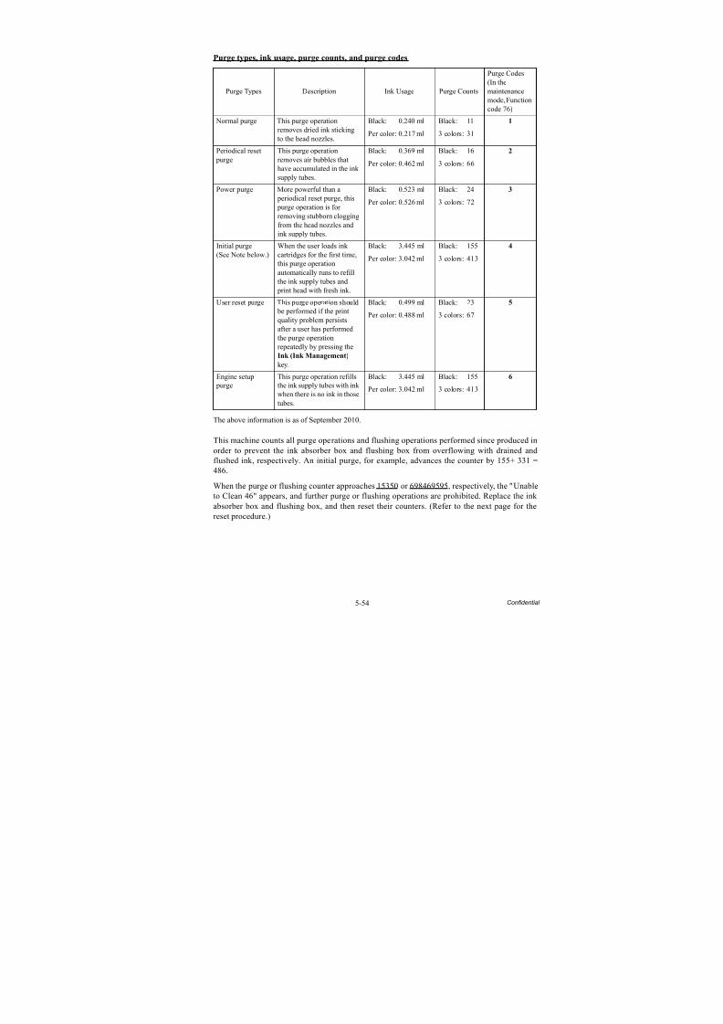
8/15/2019 Brother MFC 6510dw Sm
http://slidepdf.com/reader/full/brother-mfc-6510dw-sm 360/392
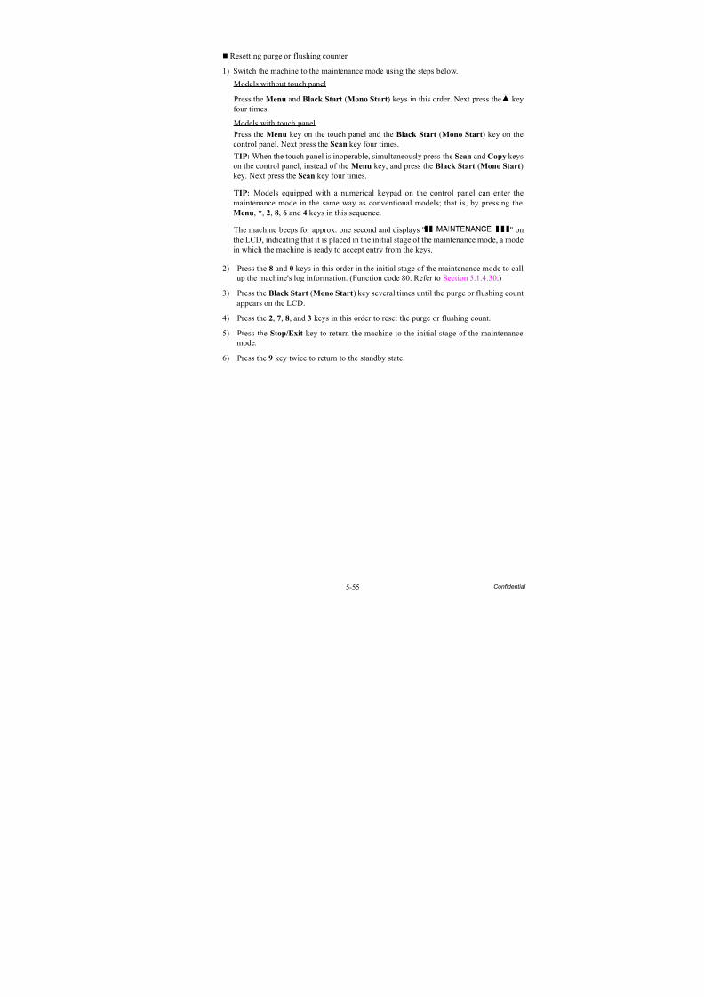
8/15/2019 Brother MFC 6510dw Sm
http://slidepdf.com/reader/full/brother-mfc-6510dw-sm 361/392
5-55 Confidential
Resetting purge or flushing counter
1) Switch the machine to the maintenance mode using the steps below.
Models without touch panel
Press the Menu and Black Start (Mono Start) keys in this order. Next press the key
four times.Models with touch panel
Press the Menu key on the touch panel and the Black Start (Mono Start) key on thecontrol panel. Next press the Scan key four times.
TIP: When the touch panel is inoperable, simultaneously press the Scan and Copy keyson the control panel, instead of the Menu key, and press the Black Start (Mono Start)key. Next press the Scan key four times.
TIP: Models equipped with a numerical keypad on the control panel can enter themaintenance mode in the same way as conventional models; that is, by pressing theMenu, *, 2, 8, 6 and 4 keys in this sequence.
The machine beeps for approx. one second and displays " " onthe LCD, indicating that it is placed in the initial stage of the maintenance mode, a modein which the machine is ready to accept entry from the keys.
2) Press the 8 and 0 keys in this order in the initial stage of the maintenance mode to callup the machine's log information. (Function code 80. Refer to Section 5.1.4.30.)
3) Press the Black Start (Mono Start) key several times until the purge or flushing countappears on the LCD.
4) Press the 2, 7, 8, and 3 keys in this order to reset the purge or flushing count.
5) Press the Stop/Exit key to return the machine to the initial stage of the maintenancemode.
6) Press the 9 key twice to return to the standby state.
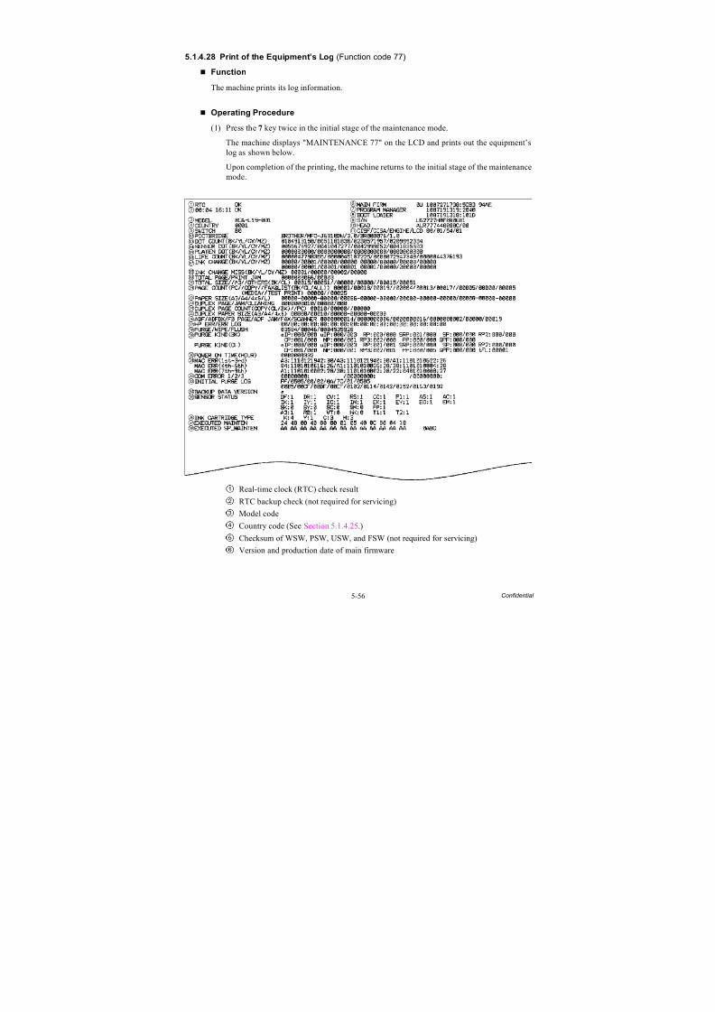
8/15/2019 Brother MFC 6510dw Sm
http://slidepdf.com/reader/full/brother-mfc-6510dw-sm 362/392
5-56 Confidential
5.1.4.28 Print of the Equipment’s Log (Function code 77)
Function
The machine prints its log information.
Operating Procedure
(1) Press the 7 key twice in the initial stage of the maintenance mode.
The machine displays "MAINTENANCE 77" on the LCD and prints out the equipment’slog as shown below.
Upon completion of the printing, the machine returns to the initial stage of the maintenancemode.
Real-time clock (RTC) check result
RTC backup check (not required for servicing)
Model code
Country code (See Section 5.1.4.25.)
Checksum of WSW, PSW, USW, and FSW (not required for servicing)
Version and production date of main firmware

8/15/2019 Brother MFC 6510dw Sm
http://slidepdf.com/reader/full/brother-mfc-6510dw-sm 363/392
5-57 Confidential
Version and production date of sub firmware
Version and production date of boot firmware
Serial number of the machine
Head property code
CIS type (first side scanning/second side scanning)/Engine type/LCD type
PictBridge information(shown only on models supporting PictBridge/USB flash memory drive)
Ink drop count, indicating how many droplets have been jetted out from each of thecurrent ink cartridges (including droplets used for purging)
Ink drop count after detection of "Ink Low," indicating how many droplets have been jetted out from each of the current ink cartridges after detection of "Ink Low"
Ink drop count, indicating how many droplets have been jetted out onto the platen in borderless printing
Total ink drop count, indicating how many droplets the machine has jetted out fromeach of the ink cartridges since produced (excluding droplets used for purging)
Ink cartridge change countUpper left: Super high-yield, color ink cartridgeUpper right: Super high-yield, black ink cartridgeLower left: High-yield, color ink cartridgeLower right:High-yield, black ink cartridge
(The BK/YL/CY/MZ on the printed equipment’s log indicate the slot positions in theink refill ASSY.)
Ink cartridge detection failure count, indicating how many times an undetectablecartridge has been inserted
Total printed page count/Total jam count
Print history for paper sizes and typesTotal printed page count (black/color)//A3 and ledger (black/color)//Other sizes (black/color)
Printed page count for PC print, copy, fax & list & report, memory card, and test print
Printed page count for paper size and paper type
Plain paper/Inkjet paper/Glossy paper
Total page count in duplex printing/Jam count in duplex printing/Switchback (SB)roller cleaning count in duplex printing
Total copy page count in duplex printing//Total PC print count in duplex printing
Printed page count for paper size and paper type in duplex printing
A3, A4: Plain paper only4 x 6: Plain paper - inkjet paper - glossy paper ADF simplex scanning page count/ADF duplex scanning page count (only for duplexscanning models)/Flat-bed scanning page count/ADF paper jam count/ADF FAXscanning count/ADF scanning count
Home positioning error code of the CIS unit/Home positioning detection log data (SeeFunction code 80. Refer to Section 5.1.4.30.)
Purge count/Wiper count/Flushing count
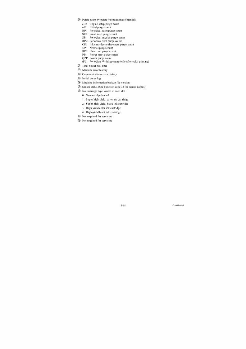
8/15/2019 Brother MFC 6510dw Sm
http://slidepdf.com/reader/full/brother-mfc-6510dw-sm 364/392
5-58 Confidential
Purge count by purge type (automatic/manual)
eIP: Engine setup purge countuIP: Initial purge countRP: Periodical reset purge countSRP: Small reset purge countSP: Periodical suction purge countRP2: Periodical vent purge countCP: Ink cartridge replacement purge count NP: Normal purge countRP3: User reset purge countPP: Power reset purge countQPP: Power purge counttFL: Periodical flushing count (only after color printing)
Total power-ON time
Machine error history
Communications error history
Initial purge logMachine information backup file version
Sensor status (See Function code 32 for sensor names.)
Ink cartridge type loaded in each slot
0: No cartridge loaded
1: Super high-yield, color ink cartridge
2: Super high-yield, black ink cartridge
3: High-yield color ink cartridge
4: High-yield black ink cartridge
Not required for servicing Not required for servicing
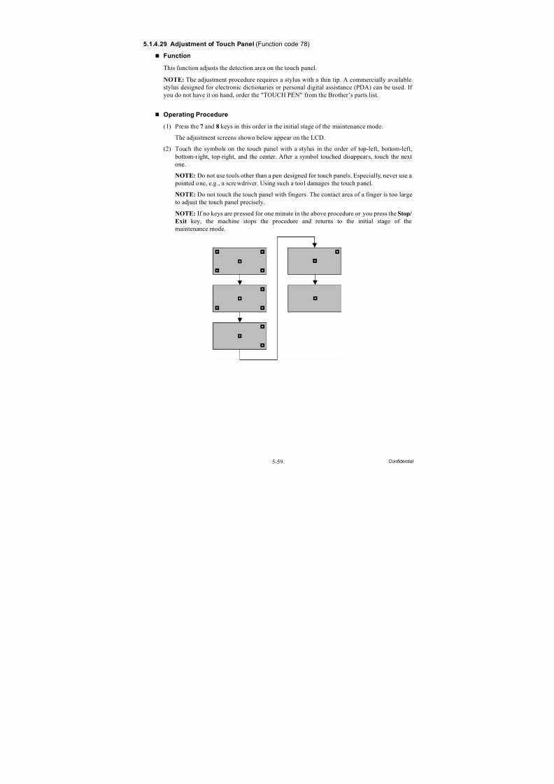
8/15/2019 Brother MFC 6510dw Sm
http://slidepdf.com/reader/full/brother-mfc-6510dw-sm 365/392
5-59 Confidential
5.1.4.29 Adjustment of Touch Panel (Function code 78)
Function
This function adjusts the detection area on the touch panel.
NOTE: The adjustment procedure requires a stylus with a thin tip. A commercially available
stylus designed for electronic dictionaries or personal digital assistance (PDA) can be used. If you do not have it on hand, order the "TOUCH PEN" from the Brother’s parts list.
Operating Procedure
(1) Press the 7 and 8 keys in this order in the initial stage of the maintenance mode.
The adjustment screens shown below appear on the LCD.
(2) Touch the symbols on the touch panel with a stylus in the order of top-left, bottom-left, bottom-right, top-right, and the center. After a symbol touched disappears, touch the nextone.
NOTE: Do not use tools other than a pen designed for touch panels. Especially, never use a pointed one, e.g., a screwdriver. Using such a tool damages the touch panel.
NOTE: Do not touch the touch panel with fingers. The contact area of a finger is too largeto adjust the touch panel precisely.
NOTE: If no keys are pressed for one minute in the above procedure or you press the Stop/
Exit key, the machine stops the procedure and returns to the initial stage of themaintenance mode.

8/15/2019 Brother MFC 6510dw Sm
http://slidepdf.com/reader/full/brother-mfc-6510dw-sm 366/392
5-60 Confidential
After the fifth symbol (center) is pressed, the "OK" appears if the adjustment is normallycompleted. After approx. three seconds, the machine returns to the initial stage of themaintenance mode.
NOTE: If the touch panel is improperly pressed or a wrong point is pressed, the "NG"appears on the LCD. After approx. three seconds, the screen returns to the state in step (2).
Start pressing the five symbols again from the first one (top-left).If the "NG" appears, repeat this procedure two or three times. If the "NG" persists evenafter that, check the touch panel harness for a contact failure, breakage, or short-circuit. If the "NG" continues to be displayed without any of such problems, replace the LCD unit.
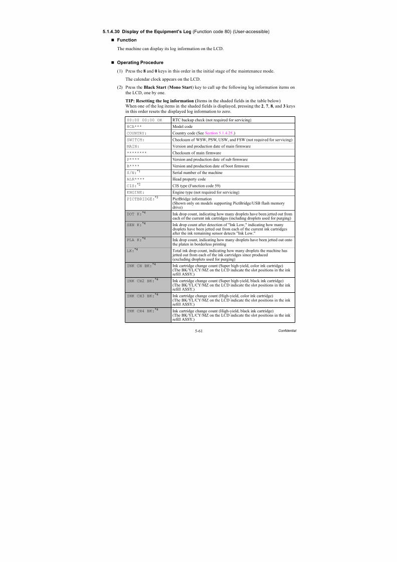
8/15/2019 Brother MFC 6510dw Sm
http://slidepdf.com/reader/full/brother-mfc-6510dw-sm 367/392
5-61 Confidential
5.1.4.30 Display of the Equipment's Log (Function code 80) (User-accessible)
Function
The machine can display its log information on the LCD.
Operating Procedure
(1) Press the 8 and 0 keys in this order in the initial stage of the maintenance mode.
The calendar clock appears on the LCD.
(2) Press the Black Start (Mono Start) key to call up the following log information items onthe LCD, one by one.
TIP: Resetting the log information (Items in the shaded fields in the table below)When one of the log items in the shaded fields is displayed, pressing the 2, 7, 8, and 3 keysin this order resets the displayed log information to zero.
00:00 00:00 OK RTC backup check (not required for servicing)
8CA*** Model codeCOUNTRY: Country code (See Section 5.1.4.25.)
SWITCH: Checksum of WSW, PSW, USW, and FSW (not required for servicing)
MAIN: Version and production date of main firmware
******** Checksum of main firmware
P**** Version and production date of sub firmware
B**** Version and production date of boot firmware
S/N:*1 Serial number of the machine
ALR**** Head property code
CIS:*2 CIS type (Function code 59)
ENGINE: Engine type (not required for servicing)
PICTBRIDGE:*3 PictBridge information(Shown only on models supporting PictBridge/USB flash memorydrive)
DOT K:*4 Ink drop count, indicating how many droplets have been jetted out fromeach of the current ink cartridges (including droplets used for purging)
SEN K:*4 Ink drop count after detection of "Ink Low," indicating how manydroplets have been jetted out from each of the current ink cartridgesafter the ink remaining sensor detects "Ink Low."
PLA K:*4 Ink drop count, indicating how many droplets have been jetted out ontothe platen in borderless printing
LK:*4
Total ink drop count, indicating how many droplets the machine has jetted out from each of the ink cartridges since produced(excluding droplets used for purging)
INK CH BK:*4 Ink cartridge change count (Super high-yield, color ink cartridge)(The BK/YL/CY/MZ on the LCD indicate the slot positions in the inkrefill ASSY.)
INK CH2 BK:*4 Ink cartridge change count (Super high-yield, black ink cartridge)(The BK/YL/CY/MZ on the LCD indicate the slot positions in the inkrefill ASSY.)
INK CH3 BK:*4 Ink cartridge change count (High-yield, color ink cartridge)(The BK/YL/CY/MZ on the LCD indicate the slot positions in the inkrefill ASSY.)
INK CH4 BK:*4 Ink cartridge change count (High-yield, black ink cartridge)
(The BK/YL/CY/MZ on the LCD indicate the slot positions in the inkrefill ASSY.)
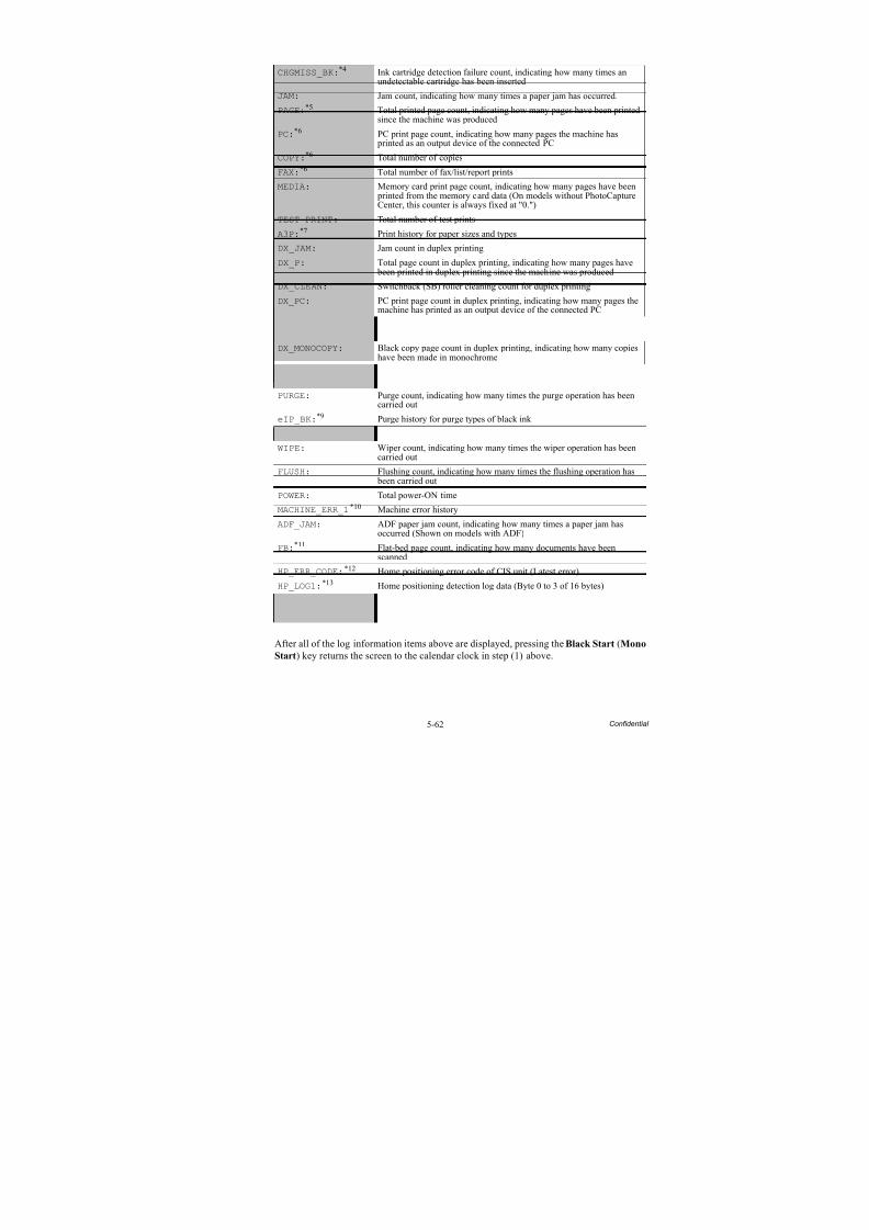
8/15/2019 Brother MFC 6510dw Sm
http://slidepdf.com/reader/full/brother-mfc-6510dw-sm 368/392
5-62 Confidential
After all of the log information items above are displayed, pressing the Black Start (Mono
Start) key returns the screen to the calendar clock in step (1) above.
CHGMISS_BK:*4 Ink cartridge detection failure count, indicating how many times anundetectable cartridge has been inserted
JAM: Jam count, indicating how many times a paper jam has occurred.
PAGE:*5 Total printed page count, indicating how many pages have been printedsince the machine was produced
PC:
*6
PC print page count, indicating how many pages the machine has printed as an output device of the connected PC
COPY:*6 Total number of copies
FAX:*6 Total number of fax/list/report prints
MEDIA: Memory card print page count, indicating how many pages have been printed from the memory card data (On models without PhotoCaptureCenter, this counter is always fixed at "0.")
TEST PRINT: Total number of test prints
A3P:*7 Print history for paper sizes and types
DX_JAM: Jam count in duplex printing
DX_P: Total page count in duplex printing, indicating how many pages have
been printed in duplex printing since the machine was producedDX_CLEAN: Switchback (SB) roller cleaning count for duplex printing
DX_PC: PC print page count in duplex printing, indicating how many pages themachine has printed as an output device of the connected PC
DX_COLORCOPY: Color copy page count in duplex printing, indicating how many copieshave been made in color
DX_MONOCOPY: Black copy page count in duplex printing, indicating how many copieshave been made in monochrome
DX_A3P:*8 Total A4 page count in duplex printing, indicating how many A4 pageshave been printed since the machine was produced
PURGE: Purge count, indicating how many times the purge operation has beencarried out
eIP_BK:*9 Purge history for purge types of black ink
eIP_CL:*9 Purge history for purge types of color inks
WIPE: Wiper count, indicating how many times the wiper operation has beencarried out
FLUSH: Flushing count, indicating how many times the flushing operation has been carried out
POWER: Total power-ON time
MACHINE_ERR_1*10 Machine error history
ADF_JAM: ADF paper jam count, indicating how many times a paper jam hasoccurred (Shown on models with ADF)
FB:
*11
Flat-bed page count, indicating how many documents have beenscanned
HP_ERR_CODE:*12 Home positioning error code of CIS unit (Latest error)
HP_LOG1:*13 Home positioning detection log data (Byte 0 to 3 of 16 bytes)
COMERR1:*14 Communications error history
BACKUP VER: Backup data file version of machine information (Function code 46)
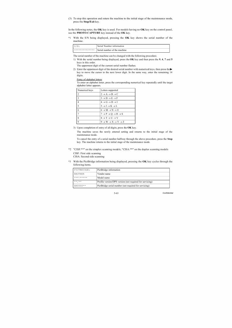
8/15/2019 Brother MFC 6510dw Sm
http://slidepdf.com/reader/full/brother-mfc-6510dw-sm 369/392
5-63 Confidential
(3) To stop this operation and return the machine to the initial stage of the maintenance mode, press the Stop/Exit key.
In the following notes, the OK key is used. For models having no OK key on the control panel,use the PHOTO CAPTURE key instead of the OK key.
*1 With the S/N being displayed, pressing the OK key shows the serial number of themachine.
The serial number of the machine can be changed with the following procedure.
1) With the serial number being displayed, press the OK key and then press the 9, 4, 7 and 5
keys in this order.The uppermost digit of the current serial number flashes.
2) Enter the uppermost digit of the desired serial number with numerical keys, then press the
key to move the cursor to the next lower digit. In the same way, enter the remaining 14digits.
Entry of alphabet lettersTo enter an alphabet letter, press the corresponding numerical key repeatedly until the targetalphabet letter appears.
3) Upon completion of entry of all digits, press the OK key.
The machine saves the newly entered setting and returns to the initial stage of themaintenance mode.
To cancel the entry of a serial number halfway through the above procedure, press the Stop
key. The machine returns to the initial stage of the maintenance mode.
*2 "CISF:**" on the simplex scanning models; "CISA:**" on the duplex scanning models
CISF: First side scanningCISA: Second side scanning
*3 With the PictBridge information being displayed, pressing the OK key cycles through thefollowing items.
S/N: Serial Number information
************** Serial number of the machine
Numerical keys Letters supported
2 2 → A → B → C
3 3 → D → E → F
4 4 → G → H → I
5 5 → J → K → L
6 6 → M → N → O7 7 → P → Q → R → S
8 8 → T → U → V
9 9 → W → X → Y → Z
PICTBRIDGE: PictBridge information
BROTHER Vendor name
***-***** Model name
**/** Profile version/DPS version (not required for servicing)
BR0000** PictBridge serial number (not required for servicing)
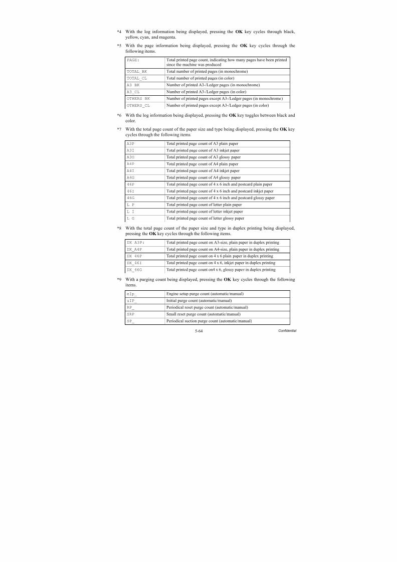
8/15/2019 Brother MFC 6510dw Sm
http://slidepdf.com/reader/full/brother-mfc-6510dw-sm 370/392
5-64 Confidential
*4 With the log information being displayed, pressing the OK key cycles through black,yellow, cyan, and magenta.
*5 With the page information being displayed, pressing the OK key cycles through thefollowing items.
*6 With the log information being displayed, pressing the OK key toggles between black andcolor.
*7 With the total page count of the paper size and type being displayed, pressing the OK keycycles through the following items.
*8 With the total page count of the paper size and type in duplex printing being displayed, pressing the OK key cycles through the following items.
*9 With a purging count being displayed, pressing the OK key cycles through the followingitems.
PAGE: Total printed page count, indicating how many pages have been printedsince the machine was produced
TOTAL_BK Total number of printed pages (in monochrome)
TOTAL_CL Total number of printed pages (in color)
A3_BK Number of printed A3-/Ledger pages (in monochrome)
A3_CL Number of printed A3-/Ledger pages (in color)
OTHERS_BK Number of printed pages except A3-/Ledger pages (in monochrome)
OTHERS_CL Number of printed pages except A3-/Ledger pages (in color)
A3P Total printed page count of A3 plain paper
A3I Total printed page count of A3 inkjet paper
A3G Total printed page count of A3 glossy paper
A4P Total printed page count of A4 plain paper
A4I Total printed page count of A4 inkjet paper
A4G Total printed page count of A4 glossy paper
46P Total printed page count of 4 x 6 inch and postcard plain paper
46I Total printed page count of 4 x 6 inch and postcard inkjet paper
46G Total printed page count of 4 x 6 inch and postcard glossy paper
L P Total printed page count of letter plain paper
L I Total printed page count of letter inkjet paper
L G Total printed page count of letter glossy paper
DX_A3P: Total printed page count on A3-size, plain paper in duplex printing
DX_A4P Total printed page count on A4-size, plain paper in duplex printing
DX_46P Total printed page count on 4 x 6 plain paper in duplex printing
DX_46I Total printed page count on 4 x 6, inkjet paper in duplex printing
DX_46G Total printed page count on4 x 6, glossy paper in duplex printing
eIp_ Engine setup purge count (automatic/manual)
uIP_ Initial purge count (automatic/manual)
RP_ Periodical reset purge count (automatic/manual)
SRP_ Small reset purge count (automatic/manual)SP_ Periodical suction purge count (automatic/manual)
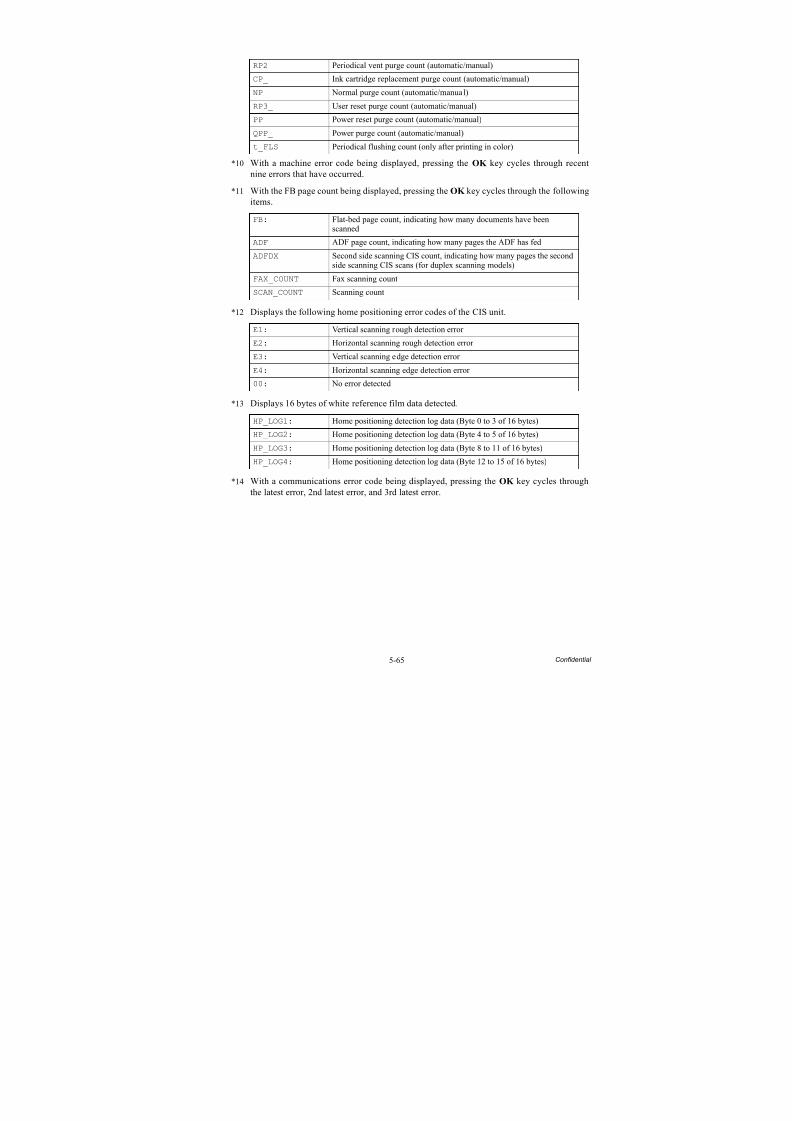
8/15/2019 Brother MFC 6510dw Sm
http://slidepdf.com/reader/full/brother-mfc-6510dw-sm 371/392
5-65 Confidential
*10 With a machine error code being displayed, pressing the OK key cycles through recentnine errors that have occurred.
*11 With the FB page count being displayed, pressing the OK key cycles through the followingitems.
*12 Displays the following home positioning error codes of the CIS unit.
*13 Displays 16 bytes of white reference film data detected.
*14 With a communications error code being displayed, pressing the OK key cycles throughthe latest error, 2nd latest error, and 3rd latest error.
RP2_ Periodical vent purge count (automatic/manual)
CP_ Ink cartridge replacement purge count (automatic/manual)
NP_ Normal purge count (automatic/manual)
RP3_ User reset purge count (automatic/manual)
PP_ Power reset purge count (automatic/manual)
QPP_ Power purge count (automatic/manual)
t_FLS Periodical flushing count (only after printing in color)
FB: Flat-bed page count, indicating how many documents have beenscanned
ADF ADF page count, indicating how many pages the ADF has fed
ADFDX Second side scanning CIS count, indicating how many pages the secondside scanning CIS scans (for duplex scanning models)
FAX_COUNT Fax scanning count
SCAN_COUNT Scanning count
E1: Vertical scanning rough detection error
E2: Horizontal scanning rough detection error
E3: Vertical scanning edge detection error
E4: Horizontal scanning edge detection error
00: No error detected
HP_LOG1: Home positioning detection log data (Byte 0 to 3 of 16 bytes)
HP_LOG2: Home positioning detection log data (Byte 4 to 5 of 16 bytes)
HP_LOG3: Home positioning detection log data (Byte 8 to 11 of 16 bytes)
HP_LOG4: Home positioning detection log data (Byte 12 to 15 of 16 bytes)
8/15/2019 Brother MFC 6510dw Sm
http://slidepdf.com/reader/full/brother-mfc-6510dw-sm 372/392
5-66 Confidential
5.1.4.31 Equipment Error Code Indication (Function code 82) (User-accessible)
Function
This function displays an error code of the last error on the LCD.
Operating Procedure
(1) Press the 8 and 2 keys in this order in the initial stage of the maintenance mode.
The LCD shows the "MACHINE ERROR X X."
(2) To stop this operation and return the machine to the initial stage of the maintenance mode, press the Stop/Exit key.
5.1.4.32 Output of Transmission Log to the Telephone Line(Function code 87) (User-
accessible)
Function
This function outputs the transmission log (that the machine has stored about the latesttransmission) to the telephone line. It allows the service personnel to receive the transmissionlog of the user's machine at a remote location and use it for analyzing problems arising in theuser's machine.
Operating Procedure
(1) If the user's machine has a transmission-related problem, call the user's machine at a remotelocation from your machine.
(2) If the line is connected, have the user perform the following:
1) Press the Menu, Black Start (Mono Start), and 0 keys in this order.
TIP: In models with touch panel, if the touch panel is inoperable, simultaneously pressthe Scan and Copy keys on the control panel instead of the Menu key, then press theBlack Start (Mono Start) and 0 keys in this order.
2) Press the 8 and 7 keys in this order.
The above operation makes the user's machine send CNG to your machine for sending
the transmission log.(3) If you hear the CNG sent from the user's machine, press the Black Start (Mono Start) key
of your machine.
Your machine will start to receive the transmission log from the user's machine.
8/15/2019 Brother MFC 6510dw Sm
http://slidepdf.com/reader/full/brother-mfc-6510dw-sm 373/392
5-67 Confidential
5.1.4.33 Assurance Mode Switch Setting(Function code 88) (User-accessible)
Function
The machine incorporates five assurance mode switches (AMS01 through AMS05) that arefirmware switches just as the ones described in Section 5.1.4.6.
When the machine does not function normally because the usage environments or operatingconditions are not usual, the assurance mode switches provide workarounds to make themachine usable by changing the machine settings to untypical ones.
The user is allowed to access the assurance mode switches under the guidance of service personnel (e.g., by telephone).
The details about AMS01 through AMS05 are described on the following pages.
Operating Procedure
(1) Press the 8 key twice in the initial stage of the maintenance mode.
The machine displays "AMS00" on the LCD and becomes ready to accept an assurancemode switch number.
(2) Enter the desired number from the assurance mode switch numbers (01 through 05).
The following appears on the LCD:
Selector 1 Selector 8
↓ ↓
AMSXX = 0 0 0 0 0 0 0 0
(3) Use the and keys to move the cursor to the selector position to be modified.
NOTE: In models with touch panel, if the , , , and keys are not displayed on thesoftware keypad, it is necessary to switch the software keypads between the numerical andfunction keypads by pressing the Scan and Copy keys simultaneously.
(4) Enter the desired number (0 or 1) using the 0 and 1 keys.
(5) Press the OK key (PHOTO CAPTURE key for models without OK key). This operationsaves the newly entered selector values onto the EEPROM and readies the machine for accepting an assurance mode switch number.
(6) Repeat steps (2) through (5) until the modification for the desired assurance mode switchesis completed.
(7) Press the Stop/Exit key to return the machine to the initial stage of the maintenance mode.
NOTES: • To cancel this operation and return the machine to the initial stage of themaintenance mode during the above procedure, press the Stop/Exit key.
• If there is a pause of more than one minute after a single-digit number is entered for double-digit assurance mode switch numbers, the machine will automaticallyreturn to the initial stage of the maintenance mode.
• Initializing the EEPROM with Function code 01 or 91 initializes the AMS switchsettings.
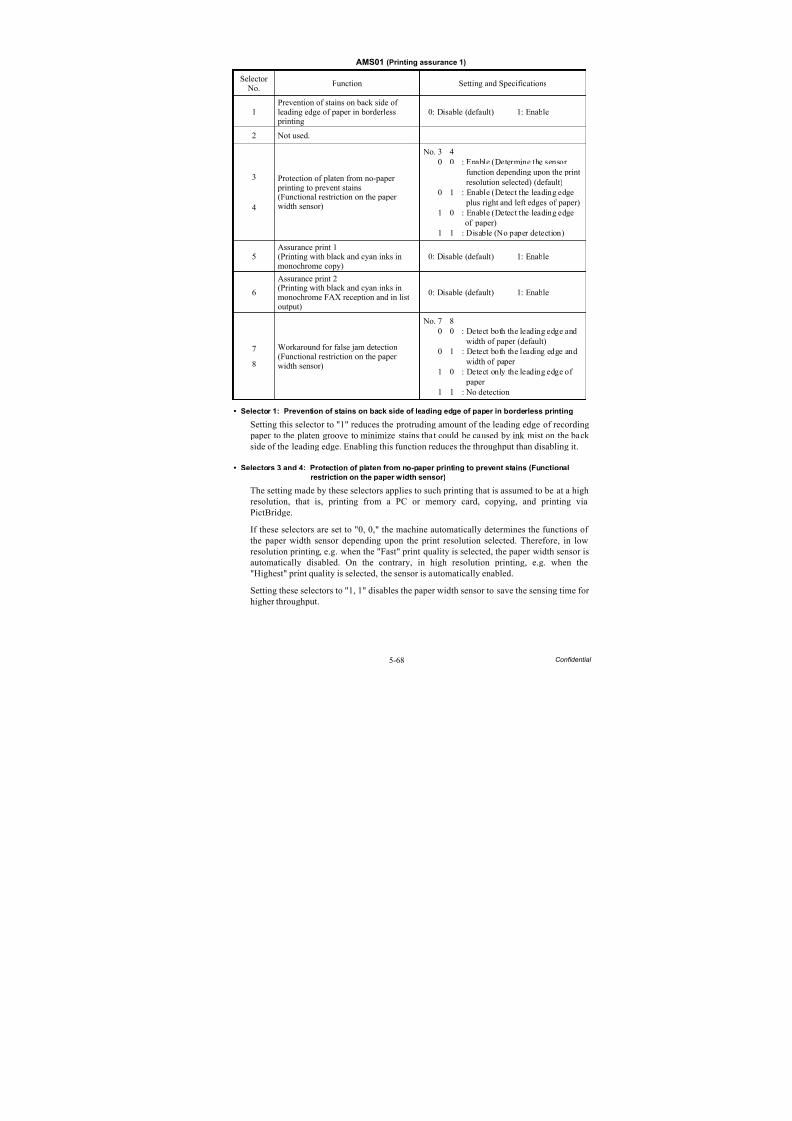
8/15/2019 Brother MFC 6510dw Sm
http://slidepdf.com/reader/full/brother-mfc-6510dw-sm 374/392
5-68 Confidential
AMS01 (Printing assurance 1)
• Selector 1: Prevention of stains on back side of leading edge of paper in borderless printing
Setting this selector to "1" reduces the protruding amount of the leading edge of recording paper to the platen groove to minimize stains that could be caused by ink mist on the back side of the leading edge. Enabling this function reduces the throughput than disabling it.
• Selectors 3 and 4: Protection of platen from no-paper printing to prevent stains (Functional
restriction on the paper width sensor)
The setting made by these selectors applies to such printing that is assumed to be at a high
resolution, that is, printing from a PC or memory card, copying, and printing viaPictBridge.
If these selectors are set to "0, 0," the machine automatically determines the functions of the paper width sensor depending upon the print resolution selected. Therefore, in lowresolution printing, e.g. when the "Fast" print quality is selected, the paper width sensor isautomatically disabled. On the contrary, in high resolution printing, e.g. when the"Highest" print quality is selected, the sensor is automatically enabled.
Setting these selectors to "1, 1" disables the paper width sensor to save the sensing time for higher throughput.
Selector No.
Function Setting and Specifications
1Prevention of stains on back side ofleading edge of paper in borderless
printing
0: Disable (default) 1: Enable
2 Not used.
3
4
Protection of platen from no-paper printing to prevent stains(Functional restriction on the paperwidth sensor)
No. 3 40 0 : Enable (Determine the sensor
function depending upon the print resolution selected) (default)
0 1 : Enable (Detect the leading edge plus right and left edges of paper)
1 0 : Enable (Detect the leading edge of paper)
1 1 : Disable (No paper detection)
5 Assurance print 1(Printing with black and cyan inks inmonochrome copy)
0: Disable (default) 1: Enable
6
Assurance print 2(Printing with black and cyan inks inmonochrome FAX reception and in listoutput)
0: Disable (default) 1: Enable
7
8
Workaround for false jam detection(Functional restriction on the paperwidth sensor)
No. 7 80 0 : Detect both the leading edge and
width of paper (default)0 1 : Detect both the leading edge and
width of paper 1 0 : Detect only the leading edge of
paper 1 1 : No detection
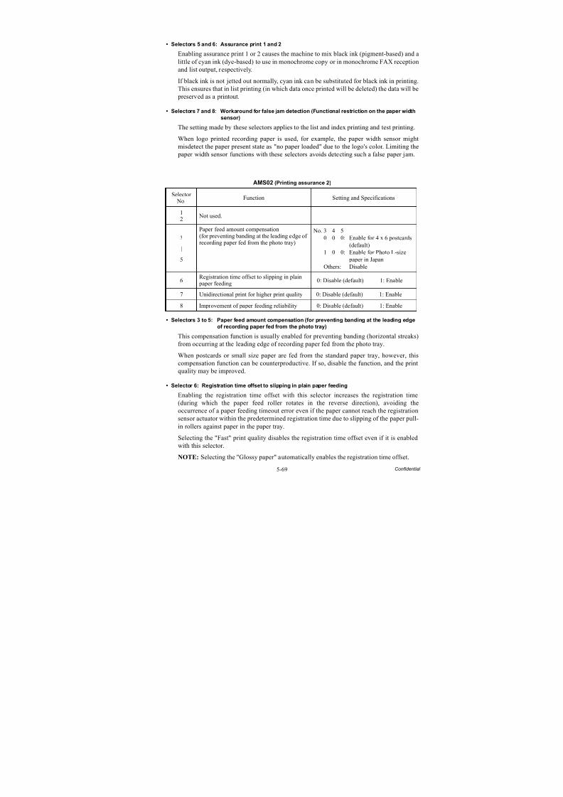
8/15/2019 Brother MFC 6510dw Sm
http://slidepdf.com/reader/full/brother-mfc-6510dw-sm 375/392
5-69 Confidential
• Selectors 5 and 6: Assurance print 1 and 2
Enabling assurance print 1 or 2 causes the machine to mix black ink (pigment-based) and alittle of cyan ink (dye-based) to use in monochrome copy or in monochrome FAX receptionand list output, respectively.
If black ink is not jetted out normally, cyan ink can be substituted for black ink in printing.
This ensures that in list printing (in which data once printed will be deleted) the data will be preserved as a printout.
• Selectors 7 and 8: Workaround for false jam detection (Functional restriction on the paper width
sensor)
The setting made by these selectors applies to the list and index printing and test printing.
When logo printed recording paper is used, for example, the paper width sensor mightmisdetect the paper present state as "no paper loaded" due to the logo's color. Limiting the paper width sensor functions with these selectors avoids detecting such a false paper jam.
AMS02 (Printing assurance 2)
• Selectors 3 to 5: Paper feed amount compensation (for preventing banding at the leading edge
of recording paper fed from the photo tray)
This compensation function is usually enabled for preventing banding (horizontal streaks)from occurring at the leading edge of recording paper fed from the photo tray.
When postcards or small size paper are fed from the standard paper tray, however, thiscompensation function can be counterproductive. If so, disable the function, and the printquality may be improved.
• Selector 6: Registration time offset to slipping in plain paper feeding
Enabling the registration time offset with this selector increases the registration time(during which the paper feed roller rotates in the reverse direction), avoiding theoccurrence of a paper feeding timeout error even if the paper cannot reach the registrationsensor actuator within the predetermined registration time due to slipping of the paper pull-in rollers against paper in the paper tray.
Selecting the "Fast" print quality disables the registration time offset even if it is enabled
with this selector.NOTE: Selecting the "Glossy paper" automatically enables the registration time offset.
Selector No.
Function Setting and Specifications
12
Not used.
3
|
5
Paper feed amount compensation(for preventing banding at the leading edge ofrecording paper fed from the photo tray)
No. 3 4 50 0 0: Enable for 4 x 6 postcards
(default)1 0 0: Enable for Photo L-size
paper in Japan
Others: Disable
6Registration time offset to slipping in plain
paper feeding 0: Disable (default) 1: Enable
7 Unidirectional print for higher print quality 0: Disable (default) 1: Enable
8 Improvement of paper feeding reliability 0: Disable (default) 1: Enable

8/15/2019 Brother MFC 6510dw Sm
http://slidepdf.com/reader/full/brother-mfc-6510dw-sm 376/392
5-70 Confidential
• Selector 7: Unidirectional print for higher print quality
The machine prints bidirectionally by default. To get higher print quality, set this selector to"1" to switch to the unidirectional print mode in which printing is performed only when thehead/carriage unit travels from left to right. Note that the unidirectional print modesacrifices the print speed.
• Selector 8: Improvement of paper feeding reliability
Setting this selector to "1" improves the paper feeding reliability, sacrificing the printspeed.
Print object Unidirectional printPrint FAX message received Yes
Copy Yes
Print from PC No
Print from memory cards or via PictBridge Yes
Print memory card index or PictBridge index Yes
Print a list Yes
Print a test pattern No
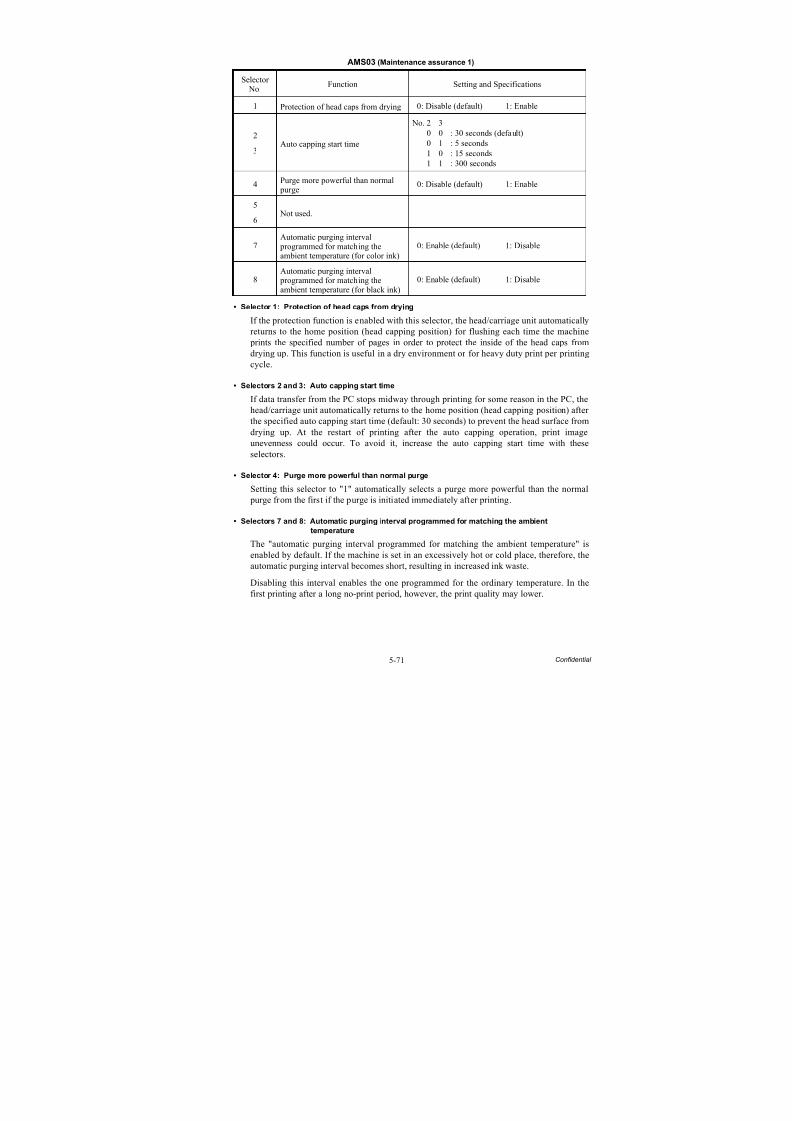
8/15/2019 Brother MFC 6510dw Sm
http://slidepdf.com/reader/full/brother-mfc-6510dw-sm 377/392
5-71 Confidential
AMS03 (Maintenance assurance 1)
• Selector 1: Protection of head caps from drying
If the protection function is enabled with this selector, the head/carriage unit automaticallyreturns to the home position (head capping position) for flushing each time the machine prints the specified number of pages in order to protect the inside of the head caps fromdrying up. This function is useful in a dry environment or for heavy duty print per printingcycle.
• Selectors 2 and 3: Auto capping start time
If data transfer from the PC stops midway through printing for some reason in the PC, thehead/carriage unit automatically returns to the home position (head capping position) after the specified auto capping start time (default: 30 seconds) to prevent the head surface fromdrying up. At the restart of printing after the auto capping operation, print imageunevenness could occur. To avoid it, increase the auto capping start time with theseselectors.
• Selector 4: Purge more powerful than normal purge
Setting this selector to "1" automatically selects a purge more powerful than the normal
purge from the first if the purge is initiated immediately after printing.
• Selectors 7 and 8: Automatic purging interval programmed for matching the ambient
temperature
The "automatic purging interval programmed for matching the ambient temperature" isenabled by default. If the machine is set in an excessively hot or cold place, therefore, theautomatic purging interval becomes short, resulting in increased ink waste.
Disabling this interval enables the one programmed for the ordinary temperature. In thefirst printing after a long no-print period, however, the print quality may lower.
Selector No.
Function Setting and Specifications
1 Protection of head caps from drying 0: Disable (default) 1: Enable
2
3Auto capping start time
No. 2 30 0 : 30 seconds (default)0 1 : 5 seconds1 0 : 15 seconds1 1 : 300 seconds
4 Purge more powerful than normal purge
0: Disable (default) 1: Enable
5
6 Not used.
7Automatic purging interval
programmed for matching theambient temperature (for color ink)
0: Enable (default) 1: Disable
8Automatic purging interval
programmed for matching theambient temperature (for black ink)
0: Enable (default) 1: Disable
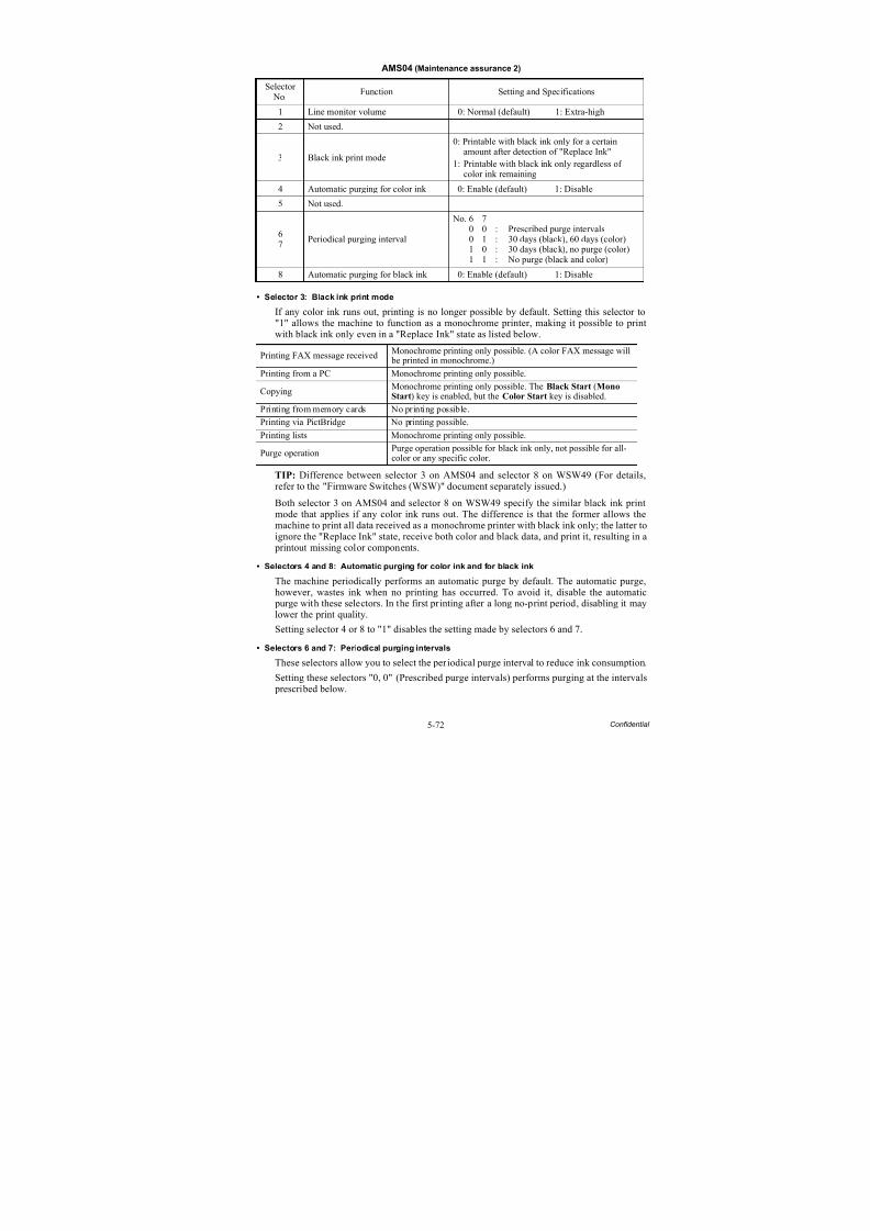
8/15/2019 Brother MFC 6510dw Sm
http://slidepdf.com/reader/full/brother-mfc-6510dw-sm 378/392
5-72 Confidential
AMS04 (Maintenance assurance 2)
• Selector 3: Black ink print mode
If any color ink runs out, printing is no longer possible by default. Setting this selector to"1" allows the machine to function as a monochrome printer, making it possible to printwith black ink only even in a "Replace Ink" state as listed below.
TIP: Difference between selector 3 on AMS04 and selector 8 on WSW49 (For details,refer to the "Firmware Switches (WSW)" document separately issued.)
Both selector 3 on AMS04 and selector 8 on WSW49 specify the similar black ink printmode that applies if any color ink runs out. The difference is that the former allows themachine to print all data received as a monochrome printer with black ink only; the latter toignore the "Replace Ink" state, receive both color and black data, and print it, resulting in a
printout missing color components.• Selectors 4 and 8: Automatic purging for color ink and for black ink
The machine periodically performs an automatic purge by default. The automatic purge,however, wastes ink when no printing has occurred. To avoid it, disable the automatic purge with these selectors. In the first printing after a long no-print period, disabling it maylower the print quality.
Setting selector 4 or 8 to "1" disables the setting made by selectors 6 and 7.
• Selectors 6 and 7: Periodical purging intervals
These selectors allow you to select the periodical purge interval to reduce ink consumption.
Setting these selectors "0, 0" (Prescribed purge intervals) performs purging at the intervals
prescribed below.
Selector No.
Function Setting and Specifications
1 Line monitor volume 0: Normal (default) 1: Extra-high
2 Not used.
3 Black ink print mode
0: Printable with black ink only for a certainamount after detection of "Replace Ink"
1: Printable with black ink only regardless ofcolor ink remaining
4 Automatic purging for color ink 0: Enable (default) 1: Disable
5 Not used.
67
Periodical purging interval
No. 6 70 0 : Prescribed purge intervals0 1 : 30 days (black), 60 days (color)1 0 : 30 days (black), no purge (color)1 1 : No purge (black and color)
8 Automatic purging for black ink 0: Enable (default) 1: Disable
Printing FAX message received Monochrome printing only possible. (A color FAX message will be printed in monochrome.)
Printing from a PC Monochrome printing only possible.
CopyingMonochrome printing only possible. The Black Start (MonoStart) key is enabled, but the Color Start key is disabled.
Printing from memory cards No printing possible.
Printing via PictBridge No printing possible.
Printing lists Monochrome printing only possible.
Purge operationPurge operation possible for black ink only, not possible for all-color or any specific color.
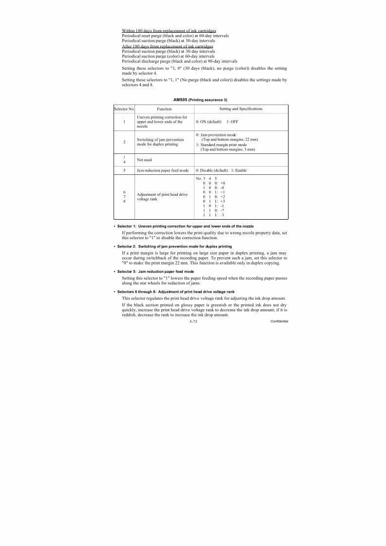
8/15/2019 Brother MFC 6510dw Sm
http://slidepdf.com/reader/full/brother-mfc-6510dw-sm 379/392
5-73 Confidential
Within 180 days from replacement of ink cartridgesPeriodical reset purge (black and color) at 60-day intervalsPeriodical suction purge (black) at 30-day intervalsAfter 180 days from replacement of ink cartridgesPeriodical suction purge (black) at 30-day intervalsPeriodical suction purge (color) at 60-day intervals
Periodical discharge purge (black and color) at 90-day intervalsSetting these selectors to "1, 0" (30 days (black), no purge (color)) disables the settingmade by selector 4.
Setting these selectors to "1, 1" (No purge (black and color)) disables the settings made byselectors 4 and 8.
AMS05 (Printing assurance 3)
• Selector 1: Uneven printing correction for upper and lower ends of the nozzle
If performing the correction lowers the print quality due to wrong nozzle property data, setthis selector to "1" to disable the correction function.
• Selector 2: Switching of jam prevention mode for duplex printing
If a print margin is large for printing on large size paper in duplex printing, a jam mayoccur during switchback of the recording paper. To prevent such a jam, set this selector to"0" to make the print margin 22 mm. This function is available only in duplex copying.
• Selector 5: Jam reduction paper feed mode
Setting this selector to "1" lowers the paper feeding speed when the recording paper passesalong the star wheels for reduction of jams.
• Selectors 6 through 8: Adjustment of print head drive voltage rank
This selector regulates the print head drive voltage rank for adjusting the ink drop amount.
If the black section printed on glossy paper is greenish or the printed ink does not dryquickly, increase the print head drive voltage rank to decrease the ink drop amount; if it isreddish, decrease the rank to increase the ink drop amount.
Selector No. Function Setting and Specifications
1
Uneven printing correction for
upper and lower ends of thenozzle 0: ON (default) 1: OFF
2Switching of jam preventionmode for duplex printing
0: Jam prevention mode (Top and bottom margins: 22 mm)
1: Standard margin print mode(Top and bottom margins: 3 mm)
34
Not used.
5 Jam reduction paper feed mode 0: Disable (default) 1: Enable
678
Adjustment of print head drivevoltage rank
No. 3 4 5
0 0 0: +01 0 0: -00 0 1: +10 1 0: +20 1 1: +31 0 1: -11 1 0: -21 1 1: -3
8/15/2019 Brother MFC 6510dw Sm
http://slidepdf.com/reader/full/brother-mfc-6510dw-sm 380/392
5-74 Confidential
5.2 OTHER SERVICE FUNCTIONS
5.2.1 Cancellation of the Pin TX Lock Mode (Not applicable to Japanese andU.S.A. models)
Function
This procedure cancels the Pin TX lock mode. Use this procedure if the user forgets his/her password entered when setting the Pin TX lock mode so as not to exit from the mode.
NOTE: Carrying out this procedure loses passwords previously entered but retains FAXmessages received in the Pin TX lock mode.
Operating Procedure
(1) Models without touch panel
When the PIN TX LOCK is displayed on the LCD, press the Menu and # keys at the same
time. Within two seconds, start to press the 2, 7, 9, 0, and 0 keys.Models with touch panel
When the PIN TX LOCK is displayed on the LCD, press the Copy and # keys at the same
time. Within two seconds, start to press the 2, 7, 9, 0, and 0 keys.
The Pin TX lock mode will be canceled and the machine returns to the calendar clock screen.
5.2.2 Displaying the Firmware Version
Pressing the * and # keys simultaneously displays the firmware version.
5.2.3 Travel of Head/Carriage Unit
Holding down the Stop/Exit key with the scanner cover opened for more than five secondsmoves the head/carriage unit.
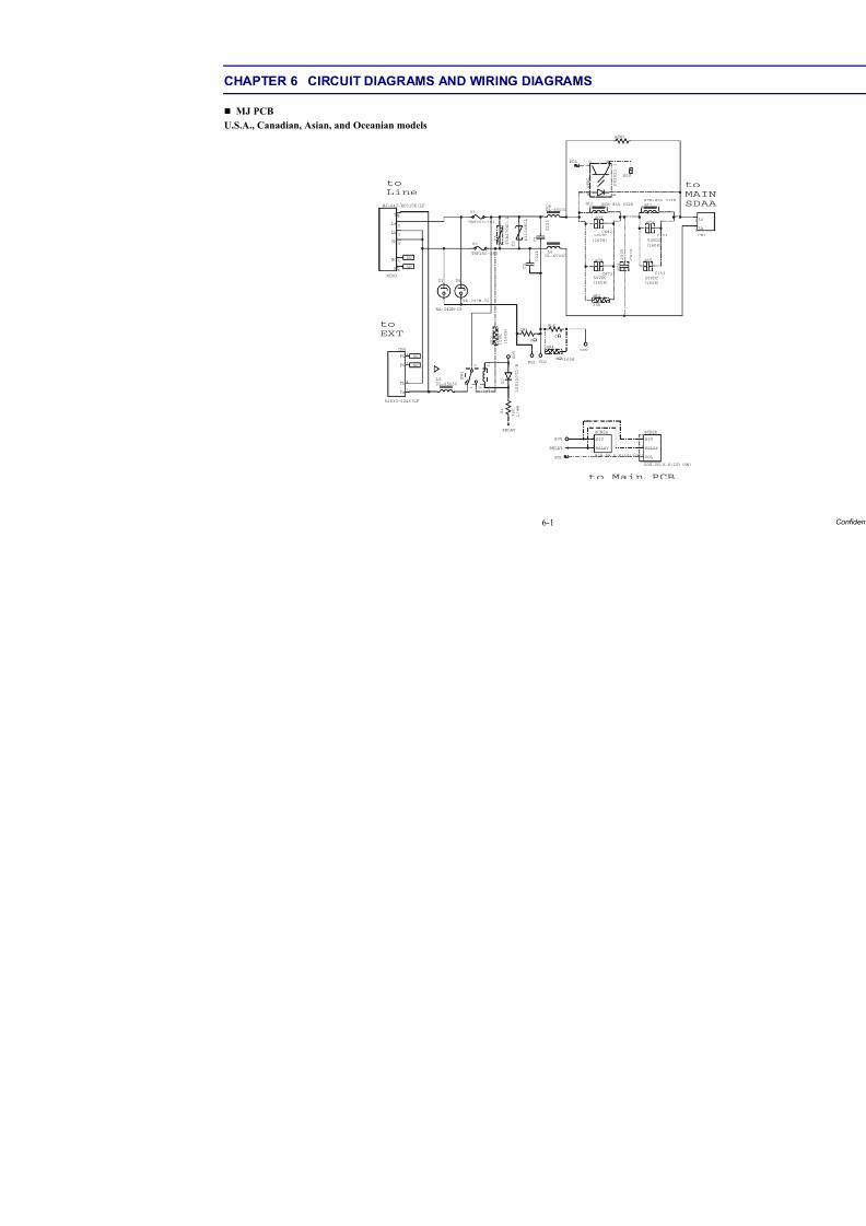
8/15/2019 Brother MFC 6510dw Sm
http://slidepdf.com/reader/full/brother-mfc-6510dw-sm 381/392
6-1
CHAPTER 6 CIRCUIT DIAGRAMS AND WIRING DIAGRAMS
MJ PCB
U.S.A., Canadian, Asian, and Oceanian models
L4DL-6503C
L6DL-6503C
S0V
POL
S0V
L5
DL-6503C
CN1
1 La
2 Lb
@CN2a
B2B-PH-K-K(LF)(SN)
1RELAY
2S0V
POL
@CN2b
B3B-PH-K-K(LF)(SN)
1POL
2RELAY
3S0V
RELAY
S0V
@ P H 1
P S 2 5 2 1
- 1
A K
E C
@ C 6
C 4 7 4
2 5 0 V
C 1
C 2 2 1
C 2
C 2 2 1
D 3
P 3 1 0 0 E C L
NC
NC
D 5
T V B 2 7 0 S C
- L
D6
RA-242M-C6
D1
RA-242M-C6
@C4
C153
50VDC
(1608)
@C5
C15350VDC
(1608)
@C8
C473
(1608)
50VDC
@C9
C68250VDC
(1608)
F1
TRF250-183
F2
TRF250-183
@L1
RCH-855 332K @L3 RCH-855 332K
FG1 FG2
@L2
0
JW3
0
@CN3
MJ-64J-RD315K(LF)
1Ta
2La
3Lb
4Tb
5NC
6NC
NC
NC
@R2
39k
@JW2
1 W S
1 2 2 1
1 1 7
3 R @
k 0 0 1
) 8 0 6 1
(
V 0 S
2 D
E -
D T 0 2 1 S S 1
1 R 0 3
3
W
4 / 1
RELAY
CN4
52830-6245(LF)
3Ta
4Tb
7FG
8FG
@R4
0 (1608)
to
MAI
SDAA
to Main PCB
to
Line
to
EXT
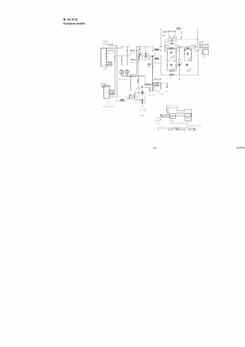
8/15/2019 Brother MFC 6510dw Sm
http://slidepdf.com/reader/full/brother-mfc-6510dw-sm 382/392
6-2
MJ PCB
European models
L4DL-6503C
L6DL-6503C
S0V
POL
S0V
L5
DL-6503C
@CN2a
B2B-PH-K-K(LF)(SN)
1RELAY
2S0V
POL
@CN2b
B3B-PH-K-K(LF)(SN
1POL
2RELAY
3S0V
RELAY
S0V
@ P H 1
P S 2 5 2
1 -
1
A K
E C
@ C 6
C 4 7 4
2 5 0 V
C 1
C 2 2 1
C 2
C 2 2 1
D 3
P 3 1 0 0 E C L
NC
NC
D 5
T V B 2 7 0 S C
- L
D6
RA-242M-C6
D1
RA-242M-C6
@C4
C153
50VDC
(1608)
@C5
C153
50VDC
(1608)
@C8
C473
(1608)
50VDC
@C9
C68250VDC
(1608)
F1
TRF250-183
F2
TRF250-183
@L1
RCH-855 332K @L3 RCH-855 332K
FG1 FG2
@L2
0
JW3
0
@CN3
MJ-64J-RD315K(LF)
1Ta
2La
3Lb
4Tb
5NC
6NC
NC
NC
@R2
39k
@JW2
1 W S
1 2 2 1
1 1 7
3 R @
k 0 0 1
) 8 0 6 1
(
V 0 S
2 D
E -
D T 0 2 1 S S 1
1 R
0 3 3
W 4
/ 1
RELAY
CN4
52830-6245(LF)
3Ta
4Tb
7FG
8FG
@R4
0 (1608)
t
M
S
to Main PCB
to
Line
to
EXT
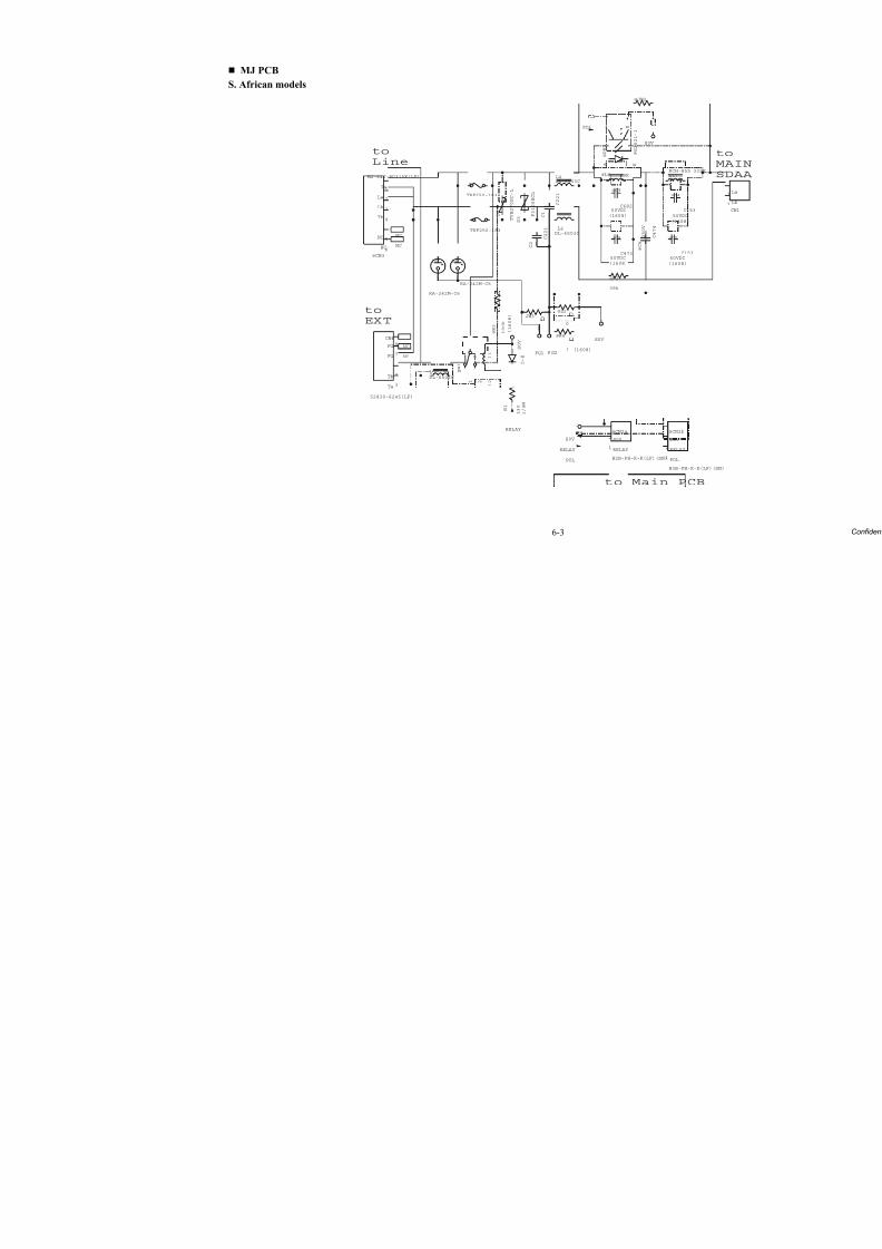
8/15/2019 Brother MFC 6510dw Sm
http://slidepdf.com/reader/full/brother-mfc-6510dw-sm 383/392
6-3
MJ PCB
S. African models
L4DL-6503C
L6DL-6503C
S0V
POL
S0V
L5
DL-6503C
@CN2a
B2B-PH-K-K(LF)(SN)
1RELAY
2S0V
POL
@CN2b
B3B-PH-K-K(LF)(SN
1POL
2RELAY
3S0V
RELAY
S0V
@ P H 1
P S 2 5 2
1 -
1
A K
E C
@ C 6
C 4 7 4
2 5 0 V
C 1
C 2 2 1
C 2
C 2 2 1
D 3
P 3 1 0 0 E C L
NC
NC
D 5
T V B 2 7 0 S C -
L
D6
RA-242M-C6
D1
RA-242M-C6
@C4
C153
50VDC
(1608)
@C5
C153
50VDC
(1608)
@C8
C473
(1608)
50VDC
@C9
C68250VDC
(1608)
F1
TRF250-183
F2
TRF250-183
@L1
RCH-855 332K @L3 39K
FG1 FG2
@L2
0
JW3
0
@CN3
MJ-64J-RD315K(LF)
1Ta
2La
3Lb
4Tb
5NC
6NC
NC
NC
@R2
39k
@JW2
1 W S
1 2 2 1
1 1 7
3 R @
k 0 0 1
) 8 0 6 1 (
V 0 S
2 D
E -
D T 0 2 1 S S 1
1 R
0 3 3
W 4 / 1
RELAY
CN4
52830-6245(LF)
3Ta
4Tb
7FG
8FG
@R4
0 (1608)
t
M
S
to Main PCB
to
Line
to
EXT
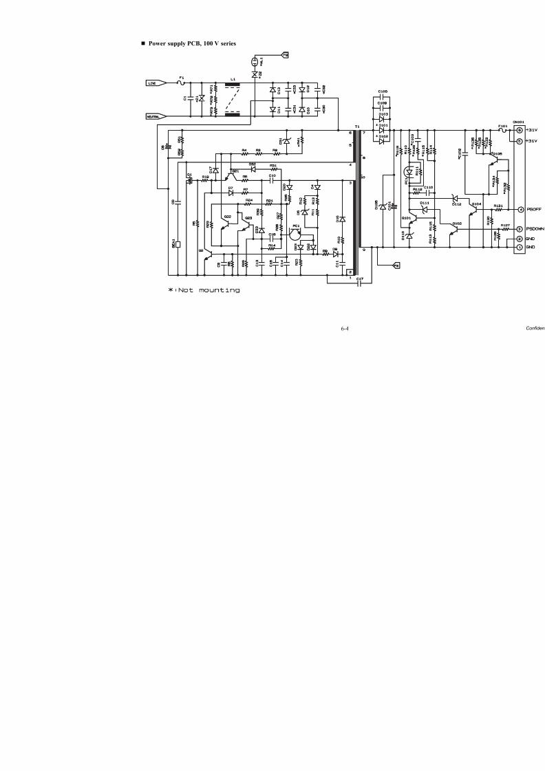
8/15/2019 Brother MFC 6510dw Sm
http://slidepdf.com/reader/full/brother-mfc-6510dw-sm 384/392
6-4
Power supply PCB, 100 V series
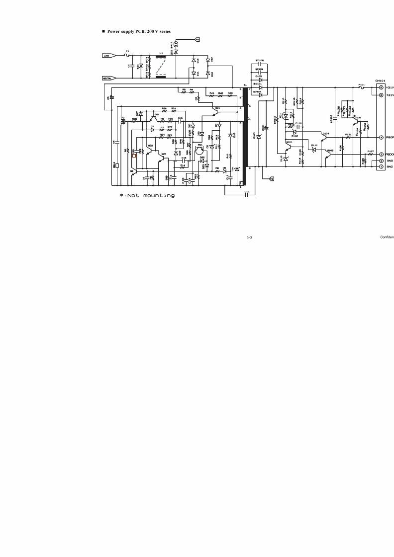
8/15/2019 Brother MFC 6510dw Sm
http://slidepdf.com/reader/full/brother-mfc-6510dw-sm 385/392
6-5
Power supply PCB, 200 V series
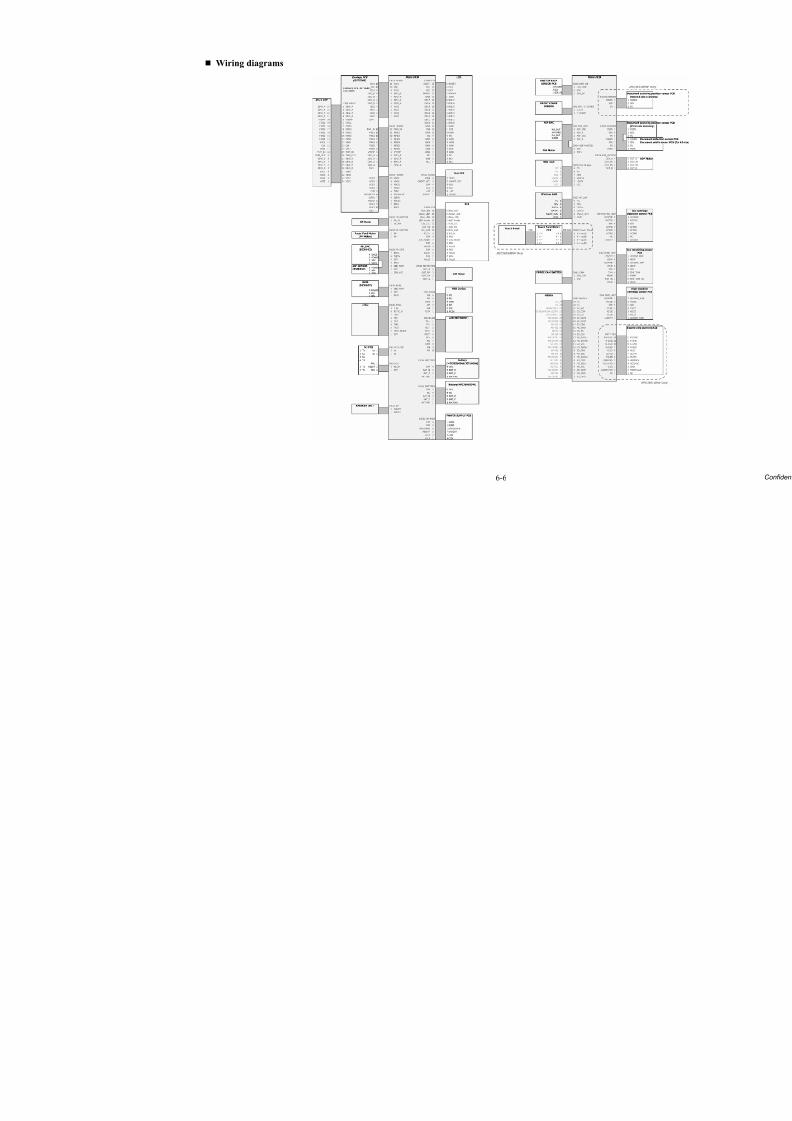
8/15/2019 Brother MFC 6510dw Sm
http://slidepdf.com/reader/full/brother-mfc-6510dw-sm 386/392
6-6
Wiring diagrams
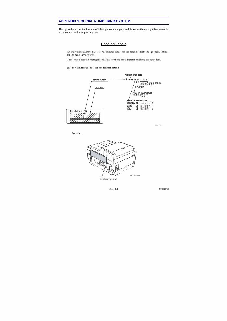
8/15/2019 Brother MFC 6510dw Sm
http://slidepdf.com/reader/full/brother-mfc-6510dw-sm 387/392
App. 1-1 Confidential
APPENDIX 1. SERIAL NUMBERING SYSTEM
This appendix shows the location of labels put on some parts and describes the coding information for
serial number and head property data.
Reading Labels
An individual machine has a "serial number label" for the machine itself and "property labels"
for the head/carriage unit.
This section lists the coding information for those serial number and head property data.
(1) Serial number label for the machine itself
Location
(app01a)
Serial number label
(app01b_M11)
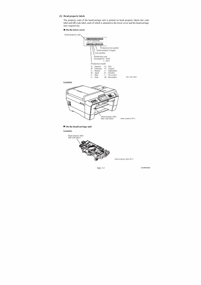
8/15/2019 Brother MFC 6510dw Sm
http://slidepdf.com/reader/full/brother-mfc-6510dw-sm 388/392
App. 1-2 Confidential
(2) Head property labels
The property code of the head/carriage unit is printed on head property labels--bar code
label and QR code label, each of which is attached to the lower cover and the head/carriage
unit, respectively.
On the lower cover
Location
On the head/carriage unit
Location
Head property code
Serial number (5-digit)
Production lot number
Production year (Example) 0 : 2010 1 : 2011
Production monthA :B :C :D :E :F :
G :H :J :K :L :M :
JulyAugustSeptember October November December
JanuaryFebruaryMarchAprilMayJune (bar_code_label)
Line number
ALR7795500000
Head property label(Bar code label) (head_property_M11)
Head property label(QR code label )
(head_property_label_M11)
8/15/2019 Brother MFC 6510dw Sm
http://slidepdf.com/reader/full/brother-mfc-6510dw-sm 389/392
App. 2-1 Confidential
APPENDIX 2. DELETION OF USER SETTING INFORMATION
This appendix provides instructions on how to delete user setting information recorded in the machine.
A2.1 Deleting User Setting Info from the Machine
The following user setting information in the machine is recorded in the EEPROM on the mainPCB. It can be deleted with the operating procedure given below.
• User's name and telephone number
• Speed dialing
• Group dialing
• Dial record (stored for redialing)
• Receiver info for fax transfer (The transfer setting will also be canceled.)• Data stored in the memory (Received data and voice messages will also be deleted.)
• Fax preview
• Fax data not yet transferred in PC-Fax receiving (Fax data already transferred to the PC willnot be deleted.)
• Fax data waiting to be sent in polling
• Receiver info for timer faxing
• Receiver info for broadcasting or batch transmission
• Caller ID history
• Activity report
• Passwords assigned by the secure function lock (for models with secure function lock)• Favorite copy settings (for models with touch panel)
• Network settings (e-mail addresses, server settings, account settings, etc.)
Operating Procedure
(1) Press the Menu key.
(2) Press the or to choose Initial Setup.
Press the OK key.
TIP: In models with touch panel, press Initial Setup.
(3) Press the or to choose Reset.
Press the OK key.
TIP: In models with touch panel, press Reset.
(4) Press or to choose All Settings.
Press the OK key.
TIP: In models with touch panel, press Yes.
(5) Press the 1 key twice to reboot the machine.
TIP: In models with touch panel, press Yes.
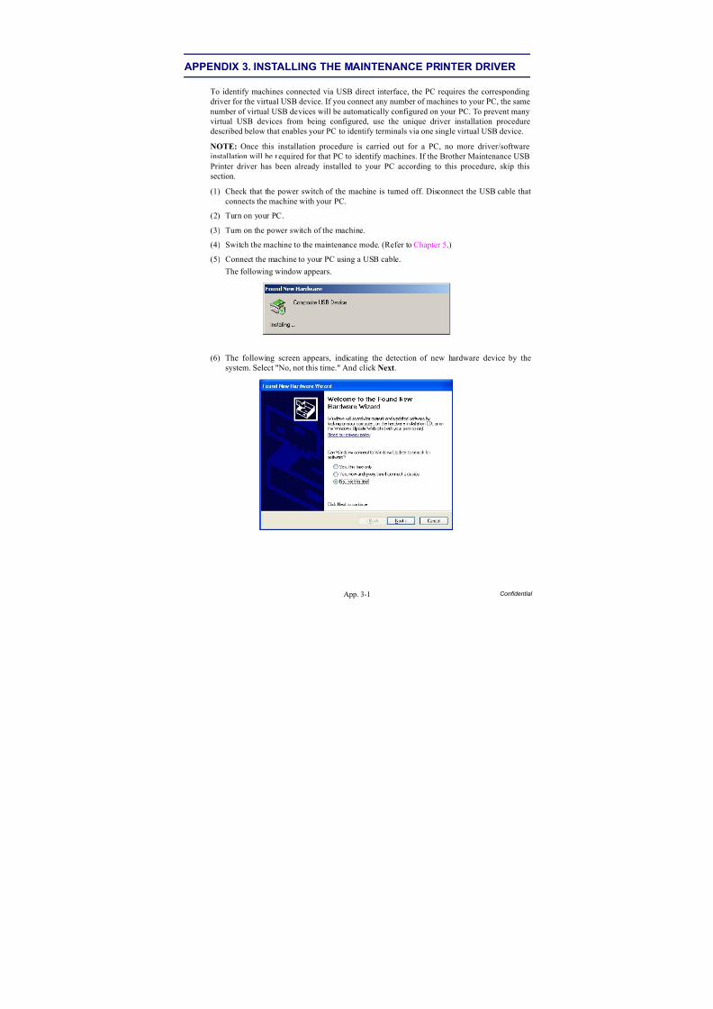
8/15/2019 Brother MFC 6510dw Sm
http://slidepdf.com/reader/full/brother-mfc-6510dw-sm 390/392
App. 3-1 Confidential
APPENDIX 3. INSTALLING THE MAINTENANCE PRINTER DRIVER
To identify machines connected via USB direct interface, the PC requires the correspondingdriver for the virtual USB device. If you connect any number of machines to your PC, the same
number of virtual USB devices will be automatically configured on your PC. To prevent manyvirtual USB devices from being configured, use the unique driver installation proceduredescribed below that enables your PC to identify terminals via one single virtual USB device.
NOTE: Once this installation procedure is carried out for a PC, no more driver/softwareinstallation will be required for that PC to identify machines. If the Brother Maintenance USBPrinter driver has been already installed to your PC according to this procedure, skip thissection.
(1) Check that the power switch of the machine is turned off. Disconnect the USB cable thatconnects the machine with your PC.
(2) Turn on your PC.
(3) Turn on the power switch of the machine.
(4) Switch the machine to the maintenance mode. (Refer to Chapter 5.)
(5) Connect the machine to your PC using a USB cable.
The following window appears.
(6) The following screen appears, indicating the detection of new hardware device by thesystem. Select "No, not this time." And click Next.
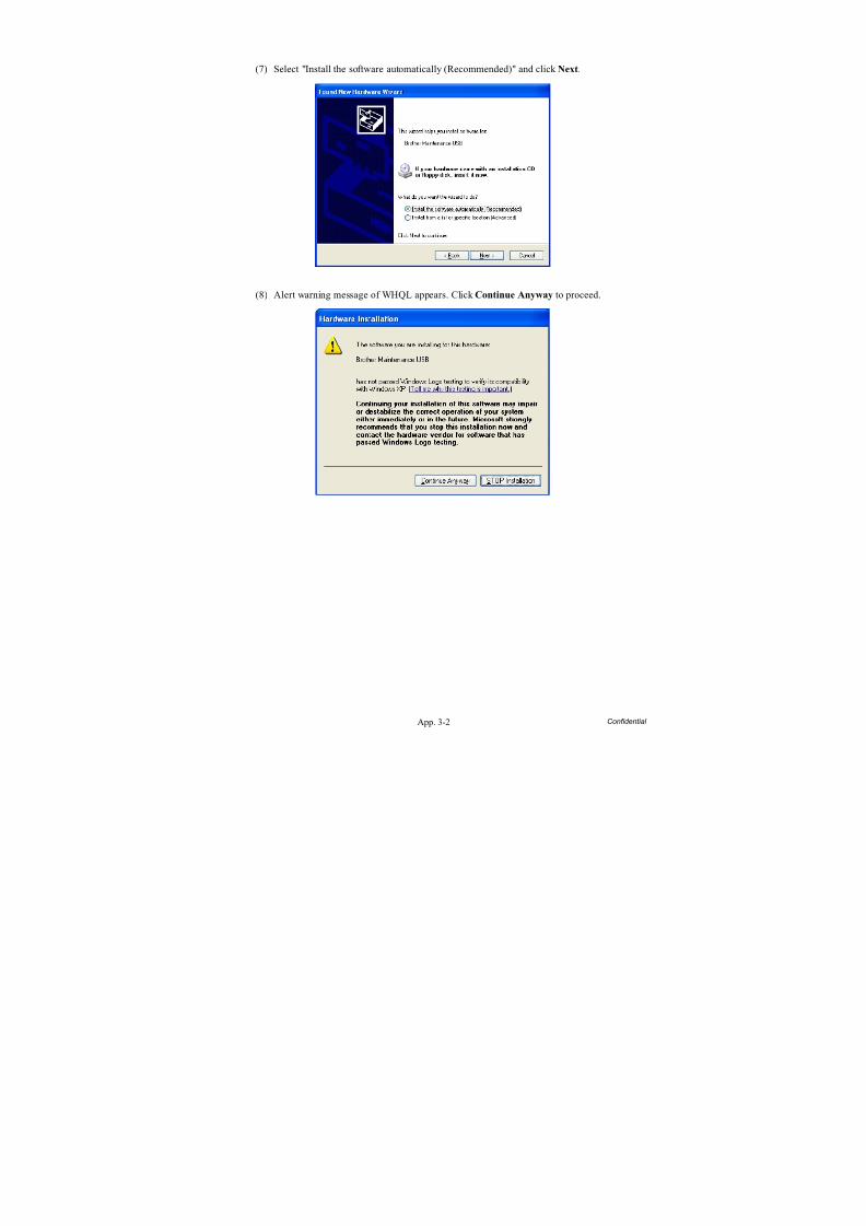
8/15/2019 Brother MFC 6510dw Sm
http://slidepdf.com/reader/full/brother-mfc-6510dw-sm 391/392
App. 3-2 Confidential
(7) Select "Install the software automatically (Recommended)" and click Next.
(8) Alert warning message of WHQL appears. Click Continue Anyway to proceed.
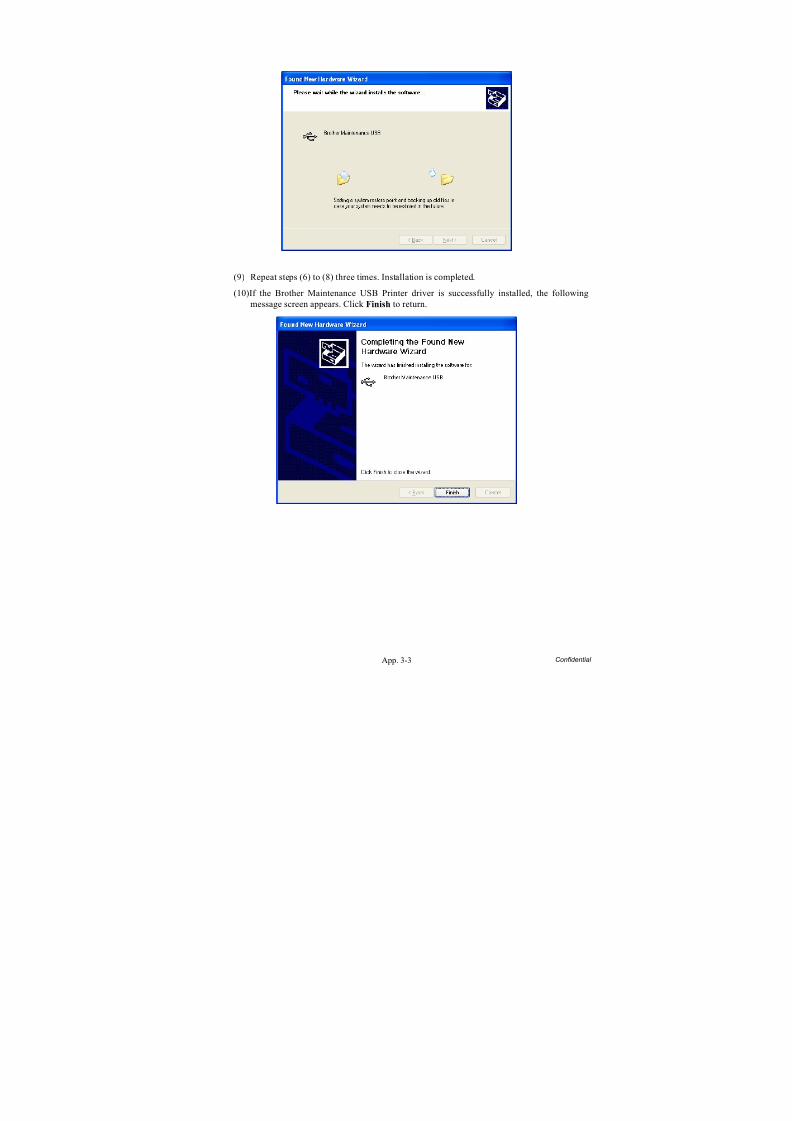
8/15/2019 Brother MFC 6510dw Sm
http://slidepdf.com/reader/full/brother-mfc-6510dw-sm 392/392
(9) Repeat steps (6) to (8) three times. Installation is completed.
(10)If the Brother Maintenance USB Printer driver is successfully installed, the followingmessage screen appears. Click Finish to return.