Brother Laser Printer HL-Series
392
Brother Laser Printer HL-Series Technical Reference Guide Revision A December, 1993 Revision B January, 1994 Addition of Appendix A "Comparison list for some models" Revision C October, 1994 Addition of the model HL-660/HL-1260
Transcript of Brother Laser Printer HL-Series
Brother Laser PrinterHL-Series
Technical Reference Guide
Revision A December, 1993Revision B January, 1994 Addition of Appendix A "Comparison list
for some models"Revision C October, 1994 Addition of the model HL-660/HL-1260

Copyright © 1993 - 1994Brother Industries Ltd.
ALL RIGHTS RESERVED
Trademark acknowledgments
Brother is a registered trademark and Twinriter a trademark of Brother Industries Ltd.PostScript is a registered trademark of Adobe Incorporated.Epson is a registered trademark and FX-850 a trademark of Seiko Epson Corporation.Hewlett Packard, HP, LaserJet and PCL are registered trademarks and LaserJet 4, HP-GL, and HP-GL/2 aretrademarks of Hewlett Packard Company.IBM is a registered trademark and Proprinter XL is a trademark of International Business MachinesCorporation.Microsoft and MS-DOS are registered trademarks, Windows is a trademark of Microsoft Corporation and.Diablo and Diablo 630 are trademarks of Xerox Corporation.Intellifont is a registered trademark of Agfa Corporation.TrueType is a trademark of Apple Computer, Inc.
All other brand and product names mentioned in this manual are registered trademarks or trademarks ofrespective companies.
Compilation and Publication
Under the supervision of Brother Industries Ltd., this manual has been compiled and published, covering thelatest product's descriptions and specifications.
The contents of this manual and the specifications of this product are subjected to change without notice.
Brother reserves the right to make changes without notice in the specifications and materials contained hereinand shall not be responsible for any damages (including consequential) caused by reliance on the materialspresented, including but not limited to typographical and other errors relating to the publication.
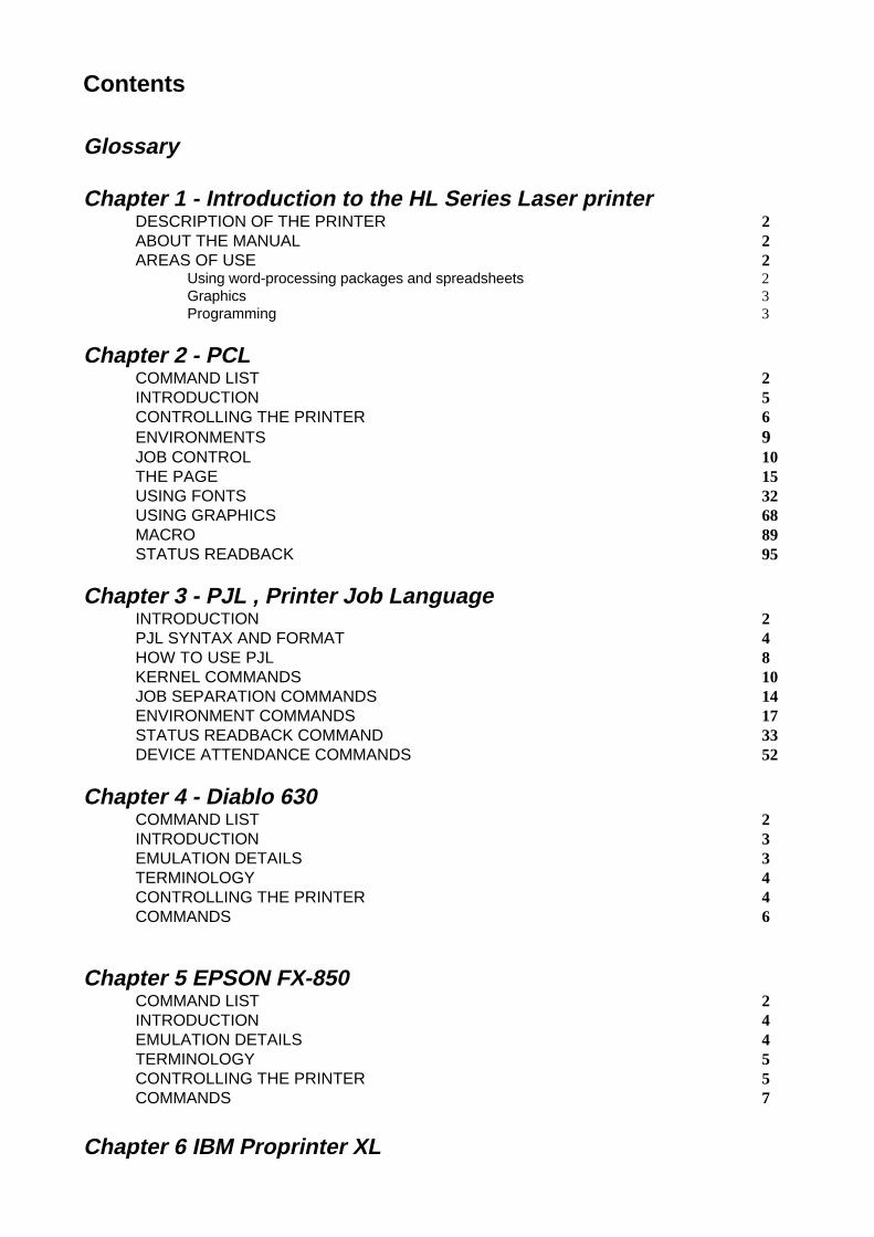
Contents
Glossary
Chapter 1 - Introduction to the HL Series Laser printerDESCRIPTION OF THE PRINTER 2ABOUT THE MANUAL 2AREAS OF USE 2
Using word-processing packages and spreadsheets 2Graphics 3Programming 3
Chapter 2 - PCLCOMMAND LIST 2INTRODUCTION 5CONTROLLING THE PRINTER 6ENVIRONMENTS 9JOB CONTROL 10THE PAGE 15USING FONTS 32USING GRAPHICS 68MACRO 89STATUS READBACK 95
Chapter 3 - PJL , Printer Job LanguageINTRODUCTION 2PJL SYNTAX AND FORMAT 4HOW TO USE PJL 8KERNEL COMMANDS 10JOB SEPARATION COMMANDS 14ENVIRONMENT COMMANDS 17STATUS READBACK COMMAND 33DEVICE ATTENDANCE COMMANDS 52
Chapter 4 - Diablo 630COMMAND LIST 2INTRODUCTION 3EMULATION DETAILS 3TERMINOLOGY 4CONTROLLING THE PRINTER 4COMMANDS 6
Chapter 5 EPSON FX-850COMMAND LIST 2INTRODUCTION 4EMULATION DETAILS 4TERMINOLOGY 5CONTROLLING THE PRINTER 5COMMANDS 7
Chapter 6 IBM Proprinter XL
COMMAND LIST 2INTRODUCTION 4EMULATION DETAILS 4NOTATION USED IN THIS EMULATION DESCRIPTION 5COMMANDS 5
Chapter 7 - Barcode Control
Chapter 8 - HP-GL/2TABLE OF CONTENTS 2INTRODUCTION 4TERMINOLOGY 4COMMAND SYNTAX 5THE HP-GL GRAPHICS WINDOW 6PREPARING TO PRINT GRAPHICS IMAGES 6COMMANDS 8
INITIALIZATION AND DEFAULT SETTING INSTRUCTIONS 8PLOT AREA AND UNIT SETTING INSTRUCTIONS 10PEN CONTROL AND PLOT INSTRUCTIONS 16THE POLYGON GROUP 25PLOT FUNCTION INSTRUCTIONS 32CHARACTER PLOT INSTRUCTIONS 44
Chapter 9 - HP-GLTABLE OF CONTENTS 2INTRODUCTION 4HP-GL SYNTAX 4FONT SELECTION 4COORDINATE SYSTEM AND PRINTING AREA 4
COORDINATE SYSTEM 4printing AREA 5
COMMANDS 6INITIALIZATION AND DEFAULT SETTING INSTRUCTIONS 6PLOT AREA AND UNIT SETTING INSTRUCTIONS 8PEN CONTROL AND PLOT INSTRUCTIONS 12THE POLYGON GROUP 21PLOT FUNCTION INSTRUCTIONS 29CHARACTER PLOT INSTRUCTIONS 33DUAL CONTEXT EXTENSIONS 43USER RESET 43FACTORY RESET 43
Appendix-A - Comparison list forHL-660, HL-1260, HL-10h, HL-10V/DV, HL-10PS/DPS, HL-8V, HL-4V, HL-4Ve and HL-6V
Glossary
Absolute plotting A method of plotting in the HP-GL and HP-GL/2 graphics language wherecoordinates are specified relative to the origin of the coordinate systemcurrently in use.
Anchor point The top left-hand corner of the PCL picture frame. You can position this onthe page using a PCL command.
Anisotropic scaling A form of image scaling using the SC command in HP-GL and HP-GL/2mode in which the user units can be of different sizes. Hence the entiregraphics window can be used to display the image.
ASCII The standard system for assigning number codes (0 ~ 255) to alphabetic,numeric and control code characters.
Attribute A characteristic of a downloadable font or a character of a Downloadable fontthat is represented by a number of a fixed length.
Bitmap font A font whose characters are defined as raster images. The characters thatmake up a bitmap font are of a fixed size.
Bold A wider line thickness for typographical characters, used to make the textstand out, for example, in headings.
Calling a macro A way of running a macro in which changes to the modified print environmentare not retained when the macro has finished running.
Cartridge A storage medium that you can insert into the printer cartridge slots.Cartridges can store fonts. The advantage of using cartridges is that theyallow you to use more fonts without taking up printer memory space.
Cartridge font A font that is stored on a cartridge. These are widely available commercially.
Character cell The imaginary grid on which downloadable characters are designed.
Character code A number assigned to a character that uniquely identifies it.
Character descriptor A block of data that describes the characteristics of an individual character ina downloadable font, such as its width and height.
Character set A selection of different characters. Characters sets normally include thealphabet in both upper- and lowercase, the digits' 0-9, punctuation marks,common mathematical symbols and a few other useful characters. There arealso some specialized character sets that are used for specific applications likemathematics. A font is defined as having a particular character set.
Column A vertical sub-division of the page whose width is equal to the HMI(horizontal motion index). The print position moves across the page onecolumn width when any single character is printed ( in a monospaced font),or when a space character is printed ( in a proportionally spaced font). Seealso HMI.
Control code An ASCII code that tells the computer to perform a particular function, suchas a carriage return.
Control panel reset A reset or factory reset performed using the printer control panel.
Cross-hatching A method of shading using perpendicular diagonal lines that cross oneanother.
Current units The current unit type in use in HP-GL and HP-GL/2 mode. Current units areeither user units or graphics units depending on whether an SC command hasbeen used.
Cursor Although the printer does not have a cursor, it is sometimes easier to visualizethe printer's operation in terms of a cursor that can be moved from place toplace on the page.
Cursor position The current position of the imaginary cursor.
Decipoint A unit of measure equal to 1/720".
Default conditions A set of HP-GL and HP-GL/2 mode settings that you restore using the DF;command. The default conditions are a subset of the initial settings.
Destination image The graphic image that is already in place on a page and to which the sourceimage is applied in the LaserJet series print model.
Dots A unit of measure equal to 1/600", the smallest increment that the cursor canmove.
Downloadable font A character font that can be downloaded from your computer to the printer.You can either buy Downloadable fonts or create your own. A downloadablefont consists of a font descriptor block followed by a character code,character descriptor block and the data for each character in the font.
Downloading The process of sending either a font, a macro or a graphic image from yourcomputer to the printer.
Effective window The area of the page on which HP-GL and HP-GL/2 output can appear. Theeffective window is determined by the overlap of the logical page, the PCLpicture frame, the hard clip and the soft clip limits.
Emulation mode A mode of operation in which the printer imitates the functions of a differentmodel.
Enabling a macro for overlayA macro that is enabled for overlay runs as the final operation before eachpage is printed, using the macro overlay environment printer settings.
Escape sequence The Esc character followed by a string of other characters that tell the printerwhich operation to perform.
Factory default environment The collection of printer settings that have been made to the printer before itleaves the factory. You can reset the printer to the factory settings either byusing a printer command or using the control panel.
Factory reset A reset in which LaserJet mode is made the current emulation mode and thefactory default environment is restored.
Fill A shading applied to a shape that you have drawn.
Fixed spacing See monospacing.
Font A collection of characters that are designed to work in harmony together. Afont has several characteristics that identify it uniquely: character or symbolset, spacing, pitch, height or point size, style, stroke weight and typeface.Fonts can either be resident in the printer's ROM, installed on cartridge ordownloaded from your computer. You can either buy downloadable fontscommercially or create your own. The word "font" is often wrongly used tomean "typeface". A font is confined to a single height or point size whereas atypeface is not.
Font descriptor A block of data that is downloaded to the printer as the first part of adownloaded font. The font descriptor describes the characteristics that arecommon to every character in the font, such as stroke weight, and containsother relevant information.
Graphics mode initial settingsThe HP-GL and HP-GL/2 mode settings that are in effect when you enter HP-GL and HP-GL/2 mode. You can restore the initial conditions using the IN;command.
Graphics units The default units of the HP-GL and HP-GL/2 coordinate system. Alsosometimes called plotter units.
Graphics window The area on the page in which HP-GL and HP-GL/2 graphic images canappear. Initially this is the same as the picture frame, but you can change thesize, position and aspect ratio of the graphics window using the IWcommand.
Gray scale A degree of continuous shading ranging from 0%, very light gray, to 100%,black.
Hard clip limits The area of the page on which it is physically possible to print using HP-GLand HP-GL/2 graphics language commands. The hard clip limits aredetermined by the size of the physical page and are equivalent to the LaserJetmode printable area.
Hatching A method of shading using parallel lines.
Height The height in typographic points (1/72") of an unaccented capital letter in afont.
HMI Horizontal motion index. The horizontal distance that the print positionmoves across the page when any single character is printed ( in a monospacedfont ), or when a space character is printed ( in a proportionally spaced font). You can set the HMI using printer commands, however, when you alterany font characteristic ( in effect, select a new font ) or switch between theprimary and secondary fonts, the HMI is reset to its default value based onthe newly selected font.
Horizontal plot size The original horizontal size of an imported HP-GL and HP-GL/2 image.
Internal font A font that is stored in the printer ROM and is therefore always available foruse, for example, Brougham 10 pitch, or a font generated from a scalabletypeface stored in the printer's ROM, for example, Tennessee bold 15 pt.
Isotropic scaling A form of image scaling using the SC command in HP-GL or HP-GL/2 modein which the user units must be of equal size. Hence it may not be possible touse the entire graphics window to display the image.
Justification The way in which text is aligned. For example, left justification involvesaligning the left end of every line of text.
Label A text string that forms part of an HP-GL and HP-GL/2 plot.
Landscape The orientation in which the top edge of the page is longer than the side edges.
Logical page The area of the physical page on which the cursor can be positioned inLaserJet mode. You can use PCL commands to specify the position of thelogical page on the physical page. Also known as the PCL addressable area.
LSB i) The least significant byte of a set of data bytes.ii) The least significant bit of a single byte of data.
Macro A sequence of PCL commands that can be stored in the printer memory. Torun the sequence you need only use a single PCL command.
Macro execution Executing a macro is a way of running a macro whereby any changes made tothe modified print environment by the macro are retained when macroexecution has been completed.
Macro overlay environment Used only by a macro that has been enabled for overlay. A combination ofthe user default environment and the modified print environment.
Medium The line thickness of normal type.
Modified print environment The collection of all current LaserJet printer settings. This environment issaved if you call a macro or enter HP-GL and HP-GL/2 mode, and thenrestored when the macro has finished running or when you quit HP-GL orHP-GL/2 mode.
Monospacing Some bitmap fonts are printed with each character occupying the same spaceon a line of text. This is known as monospacing.
MSB i) The most significant byte of a set of data bytes.ii) The most significant bit of a single byte of data.
Pattern i) The hatching or cross-hatching that can be applied to an outline shape.ii) The non-white areas of the source image in the LaserJet print model.
Pattern transparency The patterned ( non-white ) areas of the source image are either transparent,in which case the destination image is visible through the white parts of thepattern, or opaque, in which case the destination image is not visible at allthroughout the patterned areas of the source image.
PCL Printer Control Language. The language consisting of escape sequences thatis used to control the printer in LaserJet mode
PCL addressable area See logical page.
PCL picture frame See picture frame.
Pen Although this printer is a laser printer the HP-GL/2 and HP-GL graphicslanguages retains the notion of a pen and allows you to select between twopens, white and black. You must select a pen before you can draw anything.The HP-GL and HP-GL/2 language were originally developed for use withplotters and the terminology remains.
Perforation skip A feature whereby the printer automatically compensates for a page breakand resumes printing from the top of the text area on the next page.
Permanent font A downloaded font that is retained when a printer reset is performed.
Permanent macro A macro stored in the printer that will not be erased if the printer is reset.
Physical page The paper or envelope on which the printer prints.
Picture frame The area of the physical page in which HP-GL and HP-GL/2 graphic imagescan be printed.
Pitch The number of characters in one inch of text. Only applicable to monospaced(fixed pitch fonts.)
Plot A drawing produced using the HP-GL and HP-GL/2 graphics language. Socalled because the language was originally invented for use with plotters.
Plotter units See graphics units.
Point The standard unit of measurement for character height. Equal to 1/72".
Point factor scaling A form of image scaling using the SC command in HP-GL or HP-GL/2 modein which the user units and the location of the scaling point P1 are specified interms of graphics units.
Point size See height.
Polygon A shape consisting of one or more closed groups of connected lines.
Polygon buffer An area of printer memory in which you can store one or more polygons andsub-polygons defined using HP-GL and HP-GL/2 commands. Some HP-GLand HP-GL/2 commands use the polygon buffer automatically.
Portrait The orientation in which the side edges of the page are longer than the topedge.
Posture A component of a font's style - whether it is upright or italic.
Primary font In LaserJet mode the printer maintains two current font settings. The primaryfont is the first of these.
Print model A way of describing the interaction between different graphic elements (source image, pattern and destination image ).
Printable area The area of the page on which the printer can print.
Print position The position from which printing of the next character or graphic object willbegin, providing that no operations that change the print position areperformed in the interim.
Proportional spacing Fonts intended for high quality typographic output use a method of characterspacing in which the space occupied by a single character on a line of textdepends on the individual design of the character. This is known asproportional spacing. Scalable fonts are almost invariably proportionallyspaced.
RAM Random Access Memory. The printer's memory in which fonts and macroscan be stored and where pages that are to be printed are composed.
Raster graphics A method of representing a graphic image as a series of zeroes and ones thatcorrespond to white and black dots respectively.
Relative plotting A method of plotting in the HP-GL and HP-GL/2 graphics language wherecoordinates are specified relative to the point at which the last graphicscommand terminated.
Reset When you reset the printer you restore a base set of conditions. A reset caneither be performed using the control panel or by sending the printer a resetcommand. There are two types of reset, the normal reset and factory reset. Anormal reset simply restores the current emulation mode with the most recentcontrol panel settings -- it does not change the emulation mode itself. Afactory reset makes LaserJet mode the current emulation mode and restoresthe factory default environment.
Resident font See internal font.
ROM Read Only Memory. Part of the printer's memory that contains the softwarecontrolling the printer and the printer internal fonts. The ROM cannot bealtered.
Row A horizontal sub-division of the page whose height is equal to the VMI(vertical motion index). The print position moves down the page a distanceequal to the row height when a line feed is performed.
Sans serif A kind of typeface normally used for headlines. Sans serif typefaces do nothave little hooks (serifs) on the individual characters. This helps Sans serifheadline text stand out more prominently.
Scalable fonts A font for which you can specify the character size. The printer willautomatically scale the characters to the size you require.
Scaling In HP-GL or HP-GL/2 mode you can use the SC command to scale graphicimages. The three types of scaling are known as anisotropic, isotropic andpoint factor scaling.
Scaling points Two imaginary points called P1 and P2 that define a rectangular area relativeto the picture frame. You can user the HP-GL or HP-GL/2 SC and IP or IRcommands to transform and scale images by changing the relationshipbetween the two scaling points.
Scalable typeface A typeface for which you can choose a point size (height) in order to obtain aparticular font for printing. For example, you might select the Utah typeface
and then select 14 pt. as the height. The printer has many resident typefaces.You can also buy scalable typeface cartridge and disks.
Secondary font In LaserJet mode the printer maintains two current font settings. Thesecondary font is the second of these.
Serif A kind of typeface normally used for body text. Serif typefaces have littlehooks (serifs) on the individual characters that makes text more readable.
Soft clip limits See graphics window. The soft limits are determined by the IW command.
Source image The graphic image that is applied to the destination image in the LaserJetprint model. The interaction of the two images is determined by the currentsource and pattern transparency settings.
Source transparency The source image is either transparent, in which case the destination image isvisible throughout the white parts of the source image, or opaque, in whichcase the destination image is not visible at all through the source image.
Spacing The way in which a font's characters are arranged on a line of text. Seemonospacing and proportional spacing.
Stick font The default HP-GL and HP-GL/2 font consisting of thin lined characters.
Stroke weight The thickness of the lines that comprise the characters in a particular font.Medium, bold and light stroke weights are commonly used.
Sub-polygon A shape consisting of a closed group of points connected by lines. Severalsub-polygons can form one polygon.
Symbol set See character set.
Tab channel A set of up to sixteen vertical tab stops. Up to eight vertical tab channels canbe set up in the Epson FX-850 mode.
Temporary font A downloaded font that is erased from the printer's memory when a printerreset is performed. To use the font again you must download it again.
Temporary macro A macro that is erased from the printer's memory when a reset is performed.If you want to use the macro again you must redefine it and download it to theprinter again.
Text area The area of the physical page on which the printer can place text.
Text direction The orientation of printed text relative to the physical page.
TIFF Tagged Image File Format. A common file format used for storing rastergraphics data.
Transparency See pattern transparency and source transparency.
Typeface The design style of a set of typographic characters. The character design isintended to make the characters work together cohesively to produce readabletext. The word "font" is often erroneously used to mean "typeface".
User default environment The current combination of LaserJet factory default settings and settingsmade using the control panel. This is the environment that is in effect when
you switch on the printer in LaserJet mode or change to LaserJet emulationfrom another emulation mode. You can reset the printer to its user defaultsettings either by using a printer command or using the control panel.
User units Coordinate units specified by the user with the HP-GL and HP-GL/2 SCcommand.
Vector graphics A method of defining graphic images in terms of coordinates, points andlines. The HP-GL and HP-GL/2 graphics language uses this method.
Vertical plot size The original vertical size of an imported HP-GL and HP-GL/2 image.
VMI Vertical motion index. The vertical distance that the print position movesdown the page when a line feed is performed. This can be set using printercommands or with the printer's control panel by adjusting the "Lines" menuoption in PAGE FORMAT MODE.
Revision A 16/01/96
Chapter 1
Introduction
2
About the manual
This technical reference manual is intended to help you get the most out of each of the emulationmodes supported by your HL Series laserprinter. It is divided into nine sections - this introductorysection and one section for each of the emulation modes. Each emulation mode section describes thesoftware commands (the escape sequences and control codes) that you can use to make the printerperform each of its available functions. Some example programs are included to give you usefulideas.This manual is for our PCL5 models. For the differences between each model, see the Appendix"Model Comparison."
For basic set-up information, such as how to connect the printer to your computer, look in the Userguide. The User guide also describes the printers control panel and how you can set various optionsusing the keys.
Areas of use
There are several different applications for which you may want to use your HL Series laserprinter.Four general areas are outlined in the following sections.
USING WORD-PROCESSING PACKAGES AND SPREADSHEETS
You may simply wish to use the printer with your software application packages, suchas word-processors or spreadsheets. Many software packages automatically sendcommands to the printer requesting particular type styles, character sizes andspecifying page set-up information and other relevant data. In this case you will notneed to use this manual, as your software package will perform the task of controllingthe printer for you. Other packages allow you to embed software commands withinyour word-processed or spreadsheet documents. This manual describes the commandsyou need, and you can simply include them in the form that your package requires. Ineither case, read the documentation that came with your software to find out its ownspecific requirements for driving a printer.
3
GRAPHICS
HP-GL/2 or HP-GL mode offers many powerful graphic features that enable you to draw and printdetailed images quickly and easily. Many commercial graphic packages, notably computer-aideddesign applications programs, produce HP-GL/2 or HP-GL output. LaserJet mode also has severalgraphics features. You can either write your own programs to generate images or use existinggraphics software.
PROGRAMMING
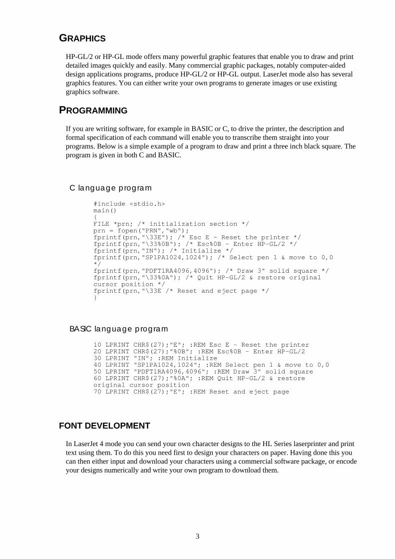
If you are writing software, for example in BASIC or C, to drive the printer, the description andformal specification of each command will enable you to transcribe them straight into yourprograms. Below is a simple example of a program to draw and print a three inch black square. Theprogram is given in both C and BASIC.
C language program
#include <stdio.h>main(){FILE *prn; /* initialization section */prn = fopen("PRN","wb");fprintf(prn,"\33E"); /* Esc E - Reset the printer */fprintf(prn,"\33%0B"); /* Esc%0B - Enter HP-GL/2 */fprintf(prn,"IN"); /* Initialize */fprintf(prn,"SP1PA1024,1024"); /* Select pen 1 & move to 0,0*/fprintf(prn,"PDFT1RA4096,4096"); /* Draw 3" solid square */fprintf(prn,"\33%0A"); /* Quit HP-GL/2 & restore originalcursor position */fprintf(prn,"\33E /* Reset and eject page */}
BASIC language program
10 LPRINT CHR$(27);"E"; :REM Esc E - Reset the printer20 LPRINT CHR$(27);"%0B"; :REM Esc%0B - Enter HP-GL/230 LPRINT "IN"; :REM Initialize40 LPRINT "SP1PA1024,1024"; :REM Select pen 1 & move to 0,050 LPRINT "PDFT1RA4096,4096"; :REM Draw 3" solid square60 LPRINT CHR$(27);"%0A"; :REM Quit HP-GL/2 & restoreoriginal cursor position70 LPRINT CHR$(27);"E"; :REM Reset and eject page
FONT DEVELOPMENT
In LaserJet 4 mode you can send your own character designs to the HL Series laserprinter and printtext using them. To do this you need first to design your characters on paper. Having done this youcan then either input and download your characters using a commercial software package, or encodeyour designs numerically and write your own program to download them.
Revision C 16/01/96
Chapter 2 "PCL" - 1
Chapter 2
PCL
Revision C 16/01/96
Chapter 2 "PCL" - 2
Command list
Control Codes 6
Escape sequences 7Esc&k#G Line Termination 8Esc&s#C End-of-line wrap 8EscY Display function mode 8EscZ Display function mode 8
Environments 9
Job Control 10Esc&l#A Page size 10Esc&l#H Paper source 11Esc&l#U Left long-edge offset registration 11Esc&l#Z Top offset registration 12Esc&l#S Simplex/Duplex printing 12Esc&a#G Paper Side Selection 12Esc&l#X Number of copies 12Esc&l1T Job separation command 13EscE Reset 13EscCR FD Reset to factory default settings 13EscCR!#R Reset to user settings 13Escz Printer self test 14Esc%-12345X Exit current emulation mode 14EscCR## Change emulation mode 14
The Page 15Esc&u#D Unit of measure 18Esc&a#L Setting the left and right margins 19Esc&a#M Setting the left and right margin 19Esc9 Resetting the horizontal margins 20Esc&l#E Setting the top margin 20Esc&l#C Setting the vertical motion index (VMI) 21Esc&k#H Setting the horizontal motion index (HMI) 21Esc&l#D Setting line spacing 23Esc&l#F Text length 23Esc&l#P Page length 24Esc&l#L Perforation skip 24Esc&a#R Vertical positioning -rows 25Esc*p#Y Vertical positioning - units 25Esc&a#V Vertical positioning - decipoints 26Esc&a#C Horizontal position - columns 26Esc*p#X Horizontal position - units 27Esc&a#H Horizontal position - decipoints 28Esc&f#S Using the cursor position stack 29Esc= Half line feed 29Esc&l#O Logical page orientation 30Esc&a#P Text direction 31
Using fonts 32Esc(3@, Esc)3@ Selecting the default fonts 34SI, SO Switching between the primary and secondary font 34Esc*c#R Symbol Set ID Code Command 36Esc(f#W Define symbol set 37Esc*c#S Symbol Set Control Command 39Esc(symbol set ID Select the symbol set 39Esc(s#C, Esc)s#C Select the symbol set 40Esc(s#P, Esc)s#P Selecting the type of character spacing 41Esc(s#H, Esc)s#H Selecting the pitch 42
Revision C 16/01/96
Chapter 2 "PCL" - 3
Esc(s#V, Esc)s#V Seelcting the height 42EscCR!#H, EscCR!#V Scaling the scalable fonts vertically or horizontally 43Esc(s#S, Esc)s#S Selecting the style 43Esc(s#B, Esc)s#B Selecting the stroke weight 44Esc(s#T, Esc)s#T Selecting the typeface 44Esc&p#X Transparent print data 45Esc&d#D, Esc&d@ Underlining text 45Esc&*c#D Font ID 46Esc*c#F Operations on downloaded fonts 46Esc(#X, Esc)#X Selecting a downloaded font 47Esc)s#W Sending the font descriptor 47Esc*c#E Sending a character code 61Esc(s#W Sending a character descriptor and data 61
Using graphics 68Esc*v#N Set source transparency 69Esc*v#O Set pattern transparency 70Esc*c#G Set area fill identity 71Esc*c#W User-defined pattern command 71Esc*p#R Set pattern reference point 72Esc*c#Q User-defined pattern control 72Esc*v#T Set pattern type 73Esc*c#A, Esc*c#H Set rectangle width 74Esc*c#B, Esc*c#V Set rectangle height 75Esc*c#P Draw filled rectangle 76Esc*t#R Set raster resolution 77EscCR ## Set high resolution control 77Esc*r#F Set raster image orientation 77Esc*r#T Set raster area height 78Esc*r#S Set raster area width 78Esc*b#Y set raster y-offset 79Esc*b#M Set compression mode 79Esc*r#A Start raster transfer 84Esc*b#W Send raster data 85Esc*b#C Compress transfer graphics 85Esc*rB End raster transfer 85Esc*rC End raster transfer 85Esc%#B Enter HP-GL/2 mode 87Esc*c0T Set picture frame anchor point 87Esc*c#Y Set picture frame vertical size 87Esc*c#X Set picture frame horizontal size 87Esc*c#L Specify vertical plot size 88Esc*c#K Specify horizontal plot size 88
Macros 89Esc&f#Y Macro ID 89Esc&f0X Start macro definition 89Esc&f1X End macro definition 90Esc&f2X Execute macro 90Esc&f3X Call macro 90Esc&f4X Enable macro for overlay 90Esc&f5X Disable macro for overlay 90Esc&f6X Delete all macros 91Esc&f7X Delete all temporary macros 91Esc&f8X Delete macro 91Esc&f9X Make macro temporary 91Esc&f1030X Delete all macros from PCMCIA memory card 91Esc&f1036X Delete macro from PCMCIA memory card 91Esc&f1038X Save macro into PCMCIA memory card 91

Revision C 16/01/96
Chapter 2 "PCL" - 4
EscCR!#E Execute Data 93Esc&b#W AppleTalk Configuration 94EscCR!1234#M MIO Video I/O port control 94
Status Readback 95Esc*s#T Set status readback location type 97Esc*s#U Set status readback location unit 97Esc*s#I Inquire status readback entity 98Esc*s1M Free space command 104Esc&r#F Flush All pages command 105Esc*s#X Echo command 105
Revision C 16/01/96
Chapter 2 "PCL" - 5
Introduction
This laserprinter provides a complete emulation of the Hewlett Packard LaserJet 4 printer. Features include rasterand vector graphics, support for bitmap and scalable fonts and page control. There are many resident fonts in theprinter and you can gain access to more by inserting a font cartridge/card or PCMCIA card into the printer or bydownloading fonts from your computer.
Revision C 16/01/96
Chapter 2 "PCL" - 6
Controlling the printer
Control codesControl codes are ASCII codes that tell the printer to perform a given function, such as a carriage return. You cansend these codes to the printer as part of a program.
Backspace (08) <08h>ASCII code 8. This code moves the cursor one column to the left.
Line feed (10) <0Ah>ASCII code 10. This code performs a line feed.
Form feed (12) <0Ch>ASCII code 12. This code ejects the most recently printed page from the printer.
Carriage return (13) <0Dh>ASCII code 13. This code performs a carriage return.
Select primary font (14) <0Eh>ASCII code 15. When you send this code to the printer subsequent characters will be printed in the currentprimary font. This is explained further in the sub-section entitled “Using fonts”.
Select secondary font (15) <0Fh>ASCII code 14. When you send this code to the printer subsequent characters will be printed in the currentsecondary font. This is explained further in the sub-section entitled “Using fonts”.
Escape (27) <1Bh>ASCII code 27. You must use this character code to start every instruction sequence that you send to the printer.
Horizontal tab (09) <09h>ASCII code 9. This code moves the cursor one tab position to the right. The tab positions are at the left margin andat the left edge of every 8th column as defined by the horizontal motion index (HMI) described in the next section,entitled “The Page”.
Space (32) <20h>ASCII code 32. This code moves the cursor one column to the right.

Revision C 16/01/96
Chapter 2 "PCL" - 7
Escape sequencesEscape sequences, also known as PCL (Printer Control Language) commands, tell the printer which operations toperform. An escape sequence consists of the Esc character followed by a string of characters which define theoperation to be performed. Some escape sequences require parameter values. These are included in the sequence asnumeric characters. The final letter of an escape sequence must be uppercase: all others must be lowercase.You can send the printer instructions by embedding escape sequences in programs or in word processeddocuments.In this manual escape sequences are shown as they would be entered, except that the character # in a sequenceindicates that a number should be included at that point in the sequence. If no number is included the printerinterprets that parameter’s value as 0.When downloading fonts or sending raster scan images to the printer the final uppercase character of the sequenceis followed by the relevant data.Two escape sequences can be combined into one if the first three characters of each sequence (including the Esccharacter itself) are the same. Hence, Esc*c45G and Esc*c2P may be combined to give Esc*c45g2P. Theuppercase ‘G’ which terminated the first sequence becomes a lowercase character in the combined sequence.combined escape sequences are executed left to right, so be careful to place commands in the order in which youwant them to be executed.
Esc*c45G Esc*c2P
Esc*c45g2P

Revision C 16/01/96
Chapter 2 "PCL" - 8
Line termination
You can set the carriage return, line feed and form feed control codes to perform compound functions. You caneither do this using the printer’s control panel (see the User Guide) or by sending the printer the following escapesequence:
• 0 = Carriage return, line feed and form feed perform their normal functions.
• 1 = Carriage return performs carriage return/line feed, line feed and form feed perform their normal functions.
• 2 = Carriage return performs its normal function, line feed performs carriage return/line feed, and form feedperforms carriage return/form feed.
• 3 = Carriage return performs carriage return/line feed, line feed performs carriage return/line feed, and formfeed performs carriage return/form feed.
0 CR→CR LF→LF FF→FF1 CR→CR+LF LF→LF FF→FF2 CR→CR LF→CR+LF FF→CR+FF3 CR→CR+LF LF→CR+LF FF→CR+FF
End-of-line wrap
If the printer tries to print a line of text that is longer than the width of the text area, the end of the line willnormally be lost. However, you can set the printer to flow text onto the next line so that text is not lost.You can turn on the automatic text wrap feature either from the printer’s control panel (see the User Guide) or bysending the printer the following escape sequence:
Esc&s0C (27)(38)(115)(48)(67) <1Bh><26h><73h><30h><43h>
To turn off the facility send:
Esc&s1C (27)(38)(115)(49)(67) <1Bh><26h><73h><31h><43h>
Display functions modeYou can choose to make the printer print escape sequences instead of executing them. Send the printer thefollowing sequence:
EscY (27)(89) <1B><59>
Now the printer prints out escape sequences and prints the characters of the control codes. It does not executethem. The only exceptions to this are CR, the carriage return code, which causes a carriage return and line feed tobe performed, and the EscZ escape sequence which turns the mode off.To turn the display functions mode off and enable escape sequences to be executed again send:
EscZ (27)(90) <1B><5A>
The printer exits the display function mode after printing a character of code 1B Hex and the letter "Z". Allsubsequent escape sequences and control codes are executed normally and not printed literally.
Revision C 16/01/96
Chapter 2 "PCL" - 9
Environments
Factory default environmentThe factory default environment is the collection of printer settings programmed into the printer before it leavesthe factory. You can restore the factory default environment using the printer’s control panel.
See the User's Guide to find how to reset the printer from the printer's control panel.Some settings cannot be restored to the factory default environment with the RESET operation from printer'scontrol panel.
User default environmentThe user default environment is a combination of factory default settings and settings which the user has madefrom the printer’s control panel or remote printer console. You can store user default setting(s) in the printer byusing the printer control panel. You can restore the user default environment either by sending the reset escapesequence to the printer, EscE, or by performing a reset from the printer’s control panel.
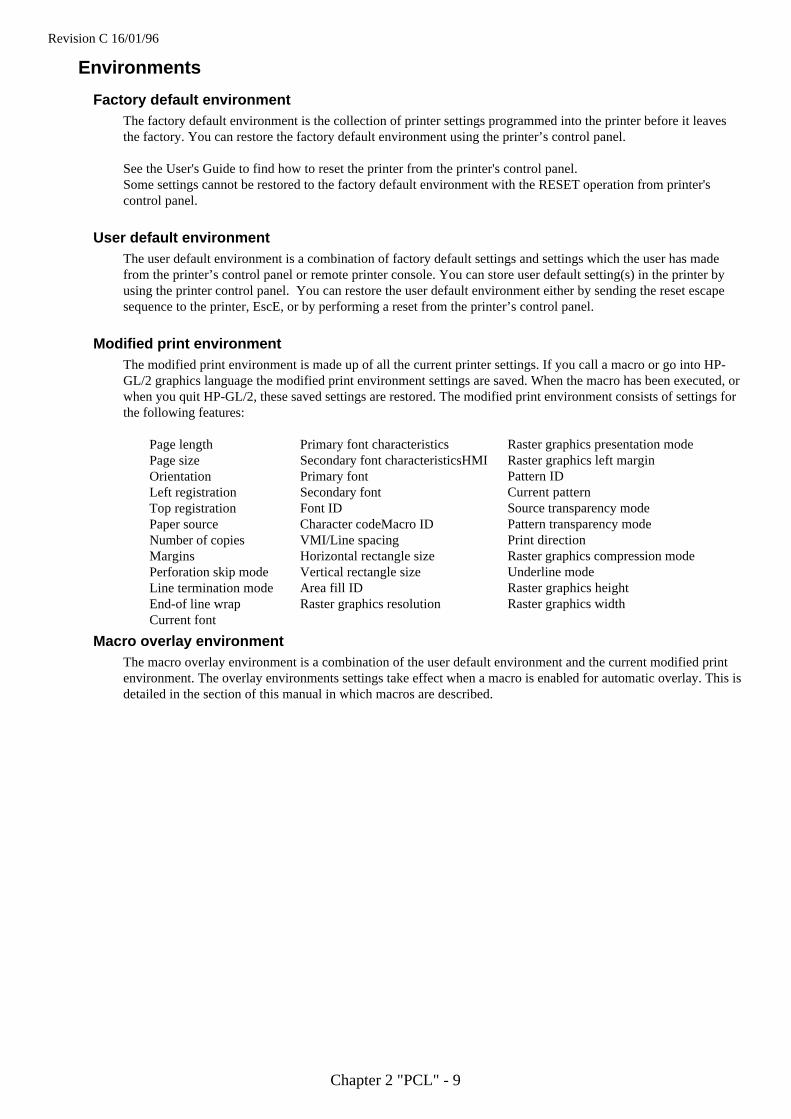
Modified print environmentThe modified print environment is made up of all the current printer settings. If you call a macro or go into HP-GL/2 graphics language the modified print environment settings are saved. When the macro has been executed, orwhen you quit HP-GL/2, these saved settings are restored. The modified print environment consists of settings forthe following features:
Page lengthPage sizeOrientationLeft registrationTop registrationPaper sourceNumber of copiesMarginsPerforation skip modeLine termination modeEnd-of line wrapCurrent font
Primary font characteristicsSecondary font characteristicsHMIPrimary fontSecondary fontFont IDCharacter codeMacro IDVMI/Line spacingHorizontal rectangle sizeVertical rectangle sizeArea fill IDRaster graphics resolution
Raster graphics presentation modeRaster graphics left marginPattern IDCurrent patternSource transparency modePattern transparency modePrint directionRaster graphics compression modeUnderline modeRaster graphics heightRaster graphics width
Macro overlay environmentThe macro overlay environment is a combination of the user default environment and the current modified printenvironment. The overlay environments settings take effect when a macro is enabled for automatic overlay. This isdetailed in the section of this manual in which macros are described.
Revision C 16/01/96
Chapter 2 "PCL" - 10
Job control
Page size
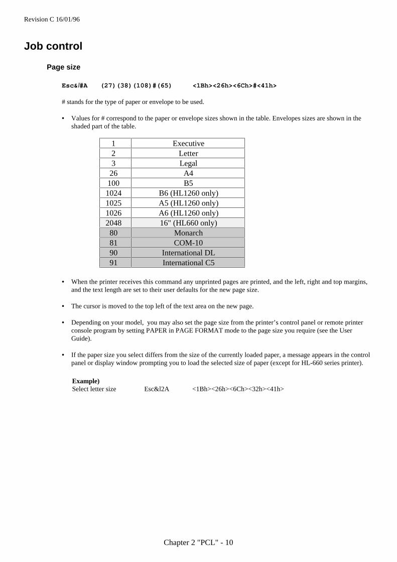
Esc&l#A (27)(38)(108)#(65) <1Bh><26h><6Ch>#<41h>
# stands for the type of paper or envelope to be used.
• Values for # correspond to the paper or envelope sizes shown in the table. Envelopes sizes are shown in theshaded part of the table.
1 Executive2 Letter3 Legal26 A4100 B51024 B6 (HL1260 only)1025 A5 (HL1260 only)1026 A6 (HL1260 only)2048 16" (HL660 only)80 Monarch81 COM-1090 International DL91 International C5
• When the printer receives this command any unprinted pages are printed, and the left, right and top margins,and the text length are set to their user defaults for the new page size.
• The cursor is moved to the top left of the text area on the new page.
• Depending on your model, you may also set the page size from the printer’s control panel or remote printerconsole program by setting PAPER in PAGE FORMAT mode to the page size you require (see the UserGuide).
• If the paper size you select differs from the size of the currently loaded paper, a message appears in the controlpanel or display window prompting you to load the selected size of paper (except for HL-660 series printer).
Example)Select letter size Esc&l2A <1Bh><26h><6Ch><32h><41h>
Revision C 16/01/96
Chapter 2 "PCL" - 11
Paper source
Esc&l#H (27)(38)(108)#(72) <1Bh><26h><6Ch>#<48h>
# denotes the paper source.
Values for # may be 0, 1, 2, 3, or 4.
• If # = 0 the current page is ejected and the paper source remains the same.• If # = 1 the current page is printed and the upper cassette becomes the paper source.• If # = 2 the current page is printed and paper is fed in manually.• If # = 3 the current page is printed and envelopes are fed in manually.• If # = 4 the current page is printed and the lower cassette becomes the paper source.• If # = 4 the current page is printed and the multi-purpose tray becomes the paper source. (HL-1260)• If # = 5 the current page is printed and the lower cassette becomes the paper source. (HL-1260)• If # = 1 or # = 2 either paper or envelopes may be fed in, depending on the current page size setting.• The cursor is positioned at the top left of the text area on the next page.
HL-10h HL-660 HL-1260#=0 Eject ←← ←←#=1 Tray 1 Sheet Feeder Tray 1#=2 Manual Feed ←← ←←#=3 Envelope N/A Envelope#=4 Tray 2 N/A MP Tray#=5 N/A Tray 2
Left long-edge offset registration
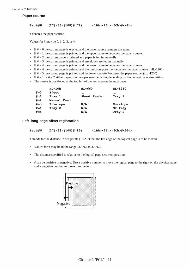
Esc&l#U (27)(38)(108)#(85) <1Bh><26h><6Ch>#<55h>
# stands for the distance in decipoints (1/720") that the left edge of the logical page is to be moved.
• Values for # may be in the range -32,767 to 32,767.
• The distance specified is relative to the logical page’s current position.
• # can be positive or negative. Use a positive number to move the logical page to the right on the physical page,and a negative number to move it to the left.
AAAAAAAAAAAAAAAAAAAAAAAAAAAAAAAAAAAAAAAAAAAAAAAAAAAAAAAAAAAAAAAAAAAAAAAAAAAAAAAAAAAAAAAAAAAA
AAAAAAAAAAAAAAAAAAAAAAAAAAAAAAAAAAAAAAAAAAAAAAAAAAAAAAAAAAAAAAAAAAAAAAAAAAAAAAAAAAAAAAAAAAAA
AAAAAAAAAAAAAAAAAAAAAAAAAAAAAAAAAAAAAAAAAAAAAAAAAAAAAAAAAAAAAAAAAAAAAAAAAAAAAAAAAAAAAAAAAAAA
AAAAAAAAAAAAAAAAAAAAAAAAAAAAAAAAAAAAAAAAAAAAAAAAAAAAAAAAAAAAAAAAAAAAAAAAAAAAAAAAAAAAAAAAAAAA
AAAAAAAAAAAAAAAAAAAAAAAAAAAAAAAAAAAAAAAAAAAAAAAAAAAAAAAAAAAAAAAAAAAAAAAAAAAAAAAAAAAAAAAAAAAA
AAAAAAAAAAAAAAAAAAAAAAAAAAAAAAAAAAAAAAAAAAAAAAAAAAAAAAAAAAAAAAAAAAAAAAAAAAAAAAAAAAAAAAAAAAAA
AAAAAAAAAAAAAAAAAAAAAAAAAAAAAAAAAAAAAAAAAAAAAAAAAAAAAAAAAAAAAAAAAAAAAAAAAAAAAAAAAAAAAAAAAAAA
AAAAAAAAAAAAAAAAAAAAAAAAAAAAAAAAAAAAAAAAAAAAAAAAAAAAAAAAAAAAAAAAAAAAAAAAAAAAAAAAAAAAAAAAAAAA
AAAAAAAAAAAAAAAAAAAAAAAAAAAAAAAAAAAAAAAAAAAAAAAAAAAAAAAAAAAAAAAAAAAAAAAAAAAAAAAAAAAAAAAAAAAA
AAAAAAAAAAAAAAAAAAAAAAAAAAAAAAAAAAAAAAAAAAAAAAAAAAAAAAAAAAAAAAAAAAAAAAAAAAAAAAAAAAAAAAAAAAAA
Positive
Negative
Revision C 16/01/96
Chapter 2 "PCL" - 12
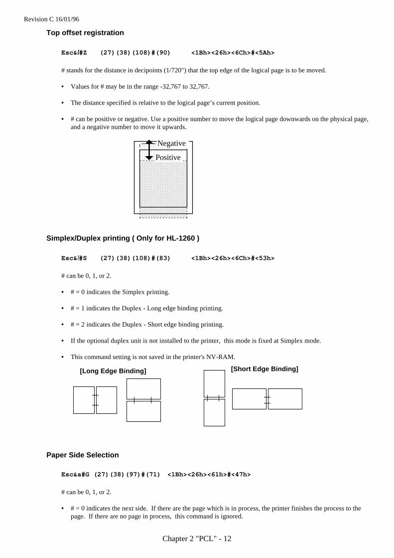
Top offset registration
Esc& ll#Z (27)(38)(108)#(90) <1Bh><26h><6Ch>#<5Ah>
# stands for the distance in decipoints (1/720") that the top edge of the logical page is to be moved.
• Values for # may be in the range -32,767 to 32,767.
• The distance specified is relative to the logical page’s current position.
• # can be positive or negative. Use a positive number to move the logical page downwards on the physical page,and a negative number to move it upwards.
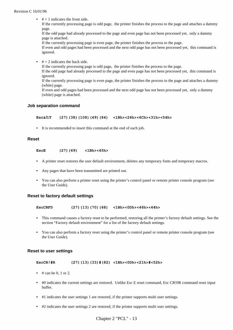
Simplex/Duplex printing ( Only for HL-1260 )
Esc&l#S (27)(38)(108)#(83) <1Bh><26h><6Ch>#<53h>
# can be 0, 1, or 2.
• # = 0 indicates the Simplex printing.
• # = 1 indicates the Duplex - Long edge binding printing.
• # = 2 indicates the Duplex - Short edge binding printing.
• If the optional duplex unit is not installed to the printer, this mode is fixed at Simplex mode.
• This command setting is not saved in the printer's NV-RAM.
Paper Side Selection
Esc&a#G (27)(38)(97)#(71) <1Bh><26h><61h>#<47h>
# can be 0, 1, or 2.
• # = 0 indicates the next side. If there are the page which is in process, the printer finishes the process to thepage. If there are no page in process, this command is ignored.
AAAAAAAAAAAAAAAAAAAAAAAAAAAAAAAAAAAAAAAAAAAAAAAAAAAAAAAAAAAAAAAAAAAAAAAAAAAAAAAAAAAAAAAAAAAA
AAAAAAAAAAAAAAAAAAAAAAAAAAAAAAAAAAAAAAAAAAAAAAAAAAAAAAAAAAAAAAAAAAAAAAAAAAAAAAAAAAAAAAAAAAAA
AAAAAAAAAAAAAAAAAAAAAAAAAAAAAAAAAAAAAAAAAAAAAAAAAAAAAAAAAAAAAAAAAAAAAAAAAAAAAAAAAAAAAAAAAAAA
AAAAAAAAAAAAAAAAAAAAAAAAAAAAAAAAAAAAAAAAAAAAAAAAAAAAAAAAAAAAAAAAAAAAAAAAAAAAAAAAAAAAAAAAAAAA
AAAAAAAAAAAAAAAAAAAAAAAAAAAAAAAAAAAAAAAAAAAAAAAAAAAAAAAAAAAAAAAAAAAAAAAAAAAAAAAAAAAAAAAAAAAA
AAAAAAAAAAAAAAAAAAAAAAAAAAAAAAAAAAAAAAAAAAAAAAAAAAAAAAAAAAAAAAAAAAAAAAAAAAAAAAAAAAAAAAAAAAAAAAAA
AAAAAAAAAAAAAAAAAAAAAAAAAAAAAAAAAAAAAAAAAAAAAAAAAAAAAAAAAAAAAAAAAAAAAAAAAAAAAAAAAAAAAAAAAAAAAAAA
AAAAAAAAAAAAAAAAAAAAAAAAAAAAAAAAAAAAAAAAAAAAAAAAAAAAAAAAAAAAAAAAAAAAAAAAAAAAAAAAAAAAAAAAAAAAAAAA
AAAAAAAAAAAAAAAAAAAAAAAAAAAAAAAAAAAAAAAAAAAAAAAAAAAAAAAAAAAAAAAAAAAAAAAAAAAAAAAAAAAAAAAAAAAAAAAA
AAAAAAAAAAAAAAAAAAAAAAAAAAAAAAAAAAAAAAAAAAAAAAAAAAAAAAAAAAAAAAAAAAAAAAAAAAAAAAAAAAAAAAAAAAAAAAAAPositive
Negative
[Long Edge Binding] [Short Edge Binding]
Revision C 16/01/96
Chapter 2 "PCL" - 13
• # = 1 indicates the front side.If the currently processing page is odd page, the printer finishes the process to the page and attaches a dammypage.If the odd page had already processed to the page and even page has not been processed yet, only a dammypage is attached.If the currently processing page is even page, the printer finishes the process to the page.If even and odd pages had been processed and the next odd page has not been processed yet, this command isignored.
• # = 2 indicates the back side.If the currently processing page is odd page, the printer finishes the process to the page.If the odd page had already processed to the page and even page has not been processed yet, this command isignored.If the currently processing page is even page, the printer finishes the process to the page and attaches a dummy(white) page.If even and odd pages had been processed and the next odd page has not been processed yet, only a dummy(white) page is attached.
Job separation command
Esc& ll1T (27)(38)(108)(49)(84) <1Bh><26h><6Ch><31h><54h>
• It is recommended to insert this command at the end of each job.
Reset
EscE (27)(69) <1Bh><45h>
• A printer reset restores the user default environment, deletes any temporary fonts and temporary macros.
• Any pages that have been transmitted are printed out.
• You can also perform a printer reset using the printer’s control panel or remote printer console program (seethe User Guide).
Reset to factory default settings
EscCRFD (27)(13)(70)(68) <1Bh><0Dh><46h><44h>
• This command causes a factory reset to be performed, restoring all the printer’s factory default settings. See thesection “Factory default environment” for a list of the factory default settings.
• You can also perform a factory reset using the printer’s control panel or remote printer console program (seethe User Guide).
Reset to user settings
EscCR!#R (27)(13)(33)#(82) <1Bh><0Dh><21h>#<52h>
• # can be 0, 1 or 2.
• #0 indicates the current settings are restored. Unlike Esc E reset command, Esc CR!0R command reset inputbuffer.
• #1 indicates the user settings 1 are restored, if the printer supports multi user settings.
• #2 indicates the user settings 2 are restored, if the printer supports multi user settings.
Revision C 16/01/96
Chapter 2 "PCL" - 14
• Depending on models you may make the control panel setting locked ("SETTING LOCK=ON"). In that case,the parameters 1 and 2 are ignored.
Printer self test
Escz (27)(122) <1Bh><7Ah>
• A printer self test causes a test sheet to be printed out to show that the machine is working properly. Dependingon the models, you may also see the test pattern for HRC setting.
Exit current emulation mode
Esc%-12345X (27)(37)(45)(49)(50)(51)(52)(53)(88)<1Bh><25h><2Dh><31h><32h><33h><34h><35h><58h>
• When the printer receives this command, all page data already received is printed out.
• All settings are reset to user settings.
• Exit the current emulation mode.
Change emulation modeEscCRGL (27)(13)(71)(76) <1Bh><0Dh><47h><4Ch>• This command changes the emulation mode to HP-GL mode.
EscCRAB (27)(13)(65)(66) <1Bh><0Dh><41h><42h>• This command changes the emulation mode to BR-Script Batch mode.
EscCRAI (27)(13)(65)(73) <1Bh><0Dh><41h><49h>• This command changes the emulation mode to BR-Script Interactive mode.
EscCRP or EscCRD (27)(13)(80) <1Bh><0Dh><50h>(27)(13)(68) <1Bh><0Dh><44h>
• These two commands change the emulation mode to Diablo 630 mode.
EscCRI (27)(13)(73) <1Bh><0Dh><49h>• This command changes the emulation mode to IBM Proprinter XL mode.
EscCRE (27)(13)(69) <1Bh><0Dh><45h>• This command changes the emulation mode to Epson FX-850 mode.
EscCRTD (27)(13)(84)(68) <1Bh><0Dh><54h><44h>• This command changes the emulation mode to Brother Twinriter DP emulation mode.
EscCRTW (27)(13)(84)(87) <1Bh><0Dh><54h><57h>• This command changes the emulation mode to Brother Twinriter WP emulation mode.
• Depending on the models, you can also switch between emulation modes using the printer’s control panel (seethe User Guide).
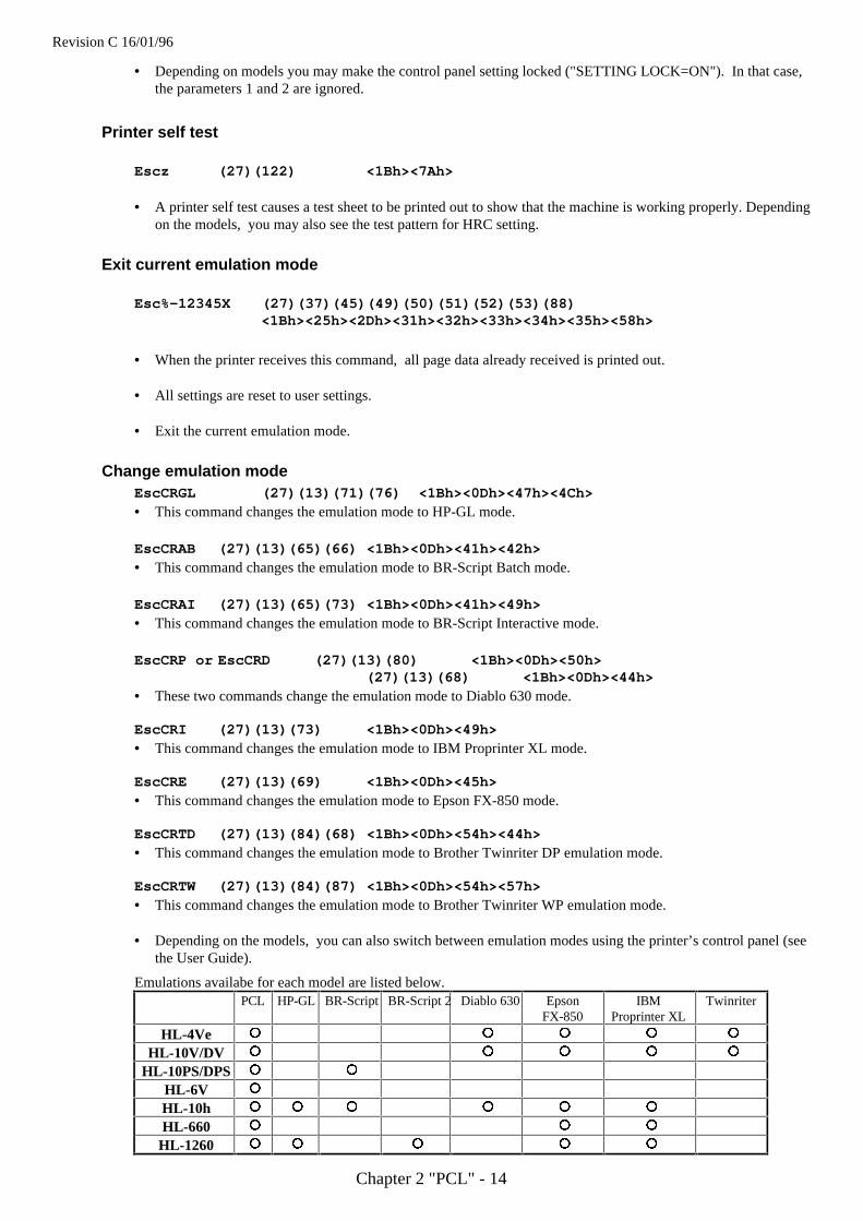
Emulations availabe for each model are listed below.PCL HP-GL BR-Script BR-Script 2 Diablo 630 Epson
FX-850IBM
Proprinter XLTwinriter
HL-4Ve ¡¡ ¡¡ ¡¡ ¡¡ ¡¡
HL-10V/DV ¡¡ ¡¡ ¡¡ ¡¡ ¡¡
HL-10PS/DPS ¡¡ ¡¡
HL-6V ¡¡
HL-10h ¡¡ ¡¡ ¡¡ ¡¡ ¡¡ ¡¡
HL-660 ¡¡ ¡¡ ¡¡
HL-1260 ¡¡ ¡¡ ¡¡ ¡¡ ¡¡
Revision C 16/01/96
Chapter 2 "PCL" - 15
The page
Physical pageThe physical page refers to the size of the paper or envelope currently in use: A4, Letter, B5, JIS B5, Legal andExecutive are the permitted paper sizes: Monarch, COM-10, International DL and International C5 are theallowable envelope sizes.
Printable areaThe printable area is a rectangular area of the physical page on which the printer can print. Its edges are 1/6" infrom the edges of the physical page.
Logical pageThe logical page is the area of the physical page where the cursor can be positioned. (Although the printer doesnot really have a cursor, we refer to the position on the page from which the printing of a character or graphicstarts as the cursor position). You can alter the size of the logical page using the left offset registration and topoffset registration commands. The logical page is also called the PCL (printer control language) addressable area.
Text areaThe text area is the area of the physical page on which text can be printed, and is determined by the left, right andtop margin settings, the text length and whether the perforation skip facility is on or off. All these settings can bemade either from the printer’s control panel (see the User Guide) or using PCL commands.
HP-GL/2 graphics windowThe HP-GL/2 graphics window is the area of the physical page on which images can be printed using HP-GL/2commands. This is described in the HP-GL/2 section of this manual. The default graphics window is bound by theleft and right edges of the logical page and horizontal boundaries half an inch below the top and above the bottomof the logical page.
Revision C 16/01/96
Chapter 2 "PCL" - 16
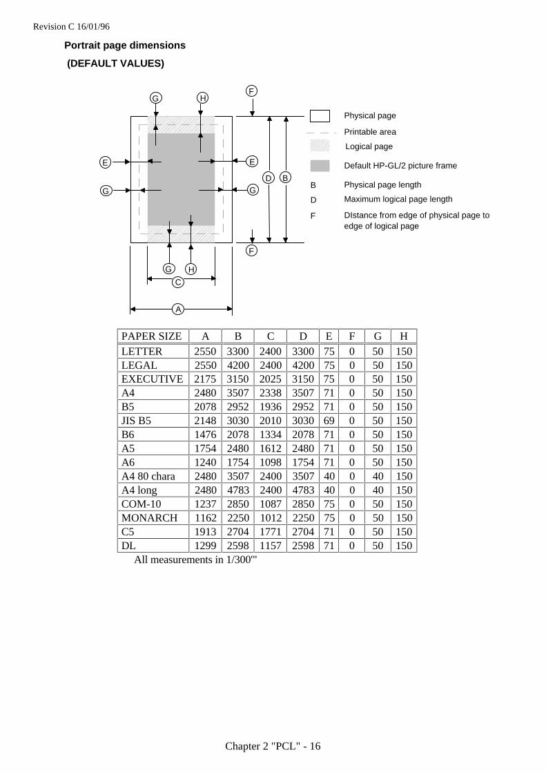
Portrait page dimensions
(DEFAULT VALUES)
A
B
C
D
E
F
G HF
G H
E
G G
Physical page
Printable area
Logical page
Default HP-GL/2 picture frame
B Physical page length
D Maximum logical page length
F DIstance from edge of physical page toedge of logical page
PAPER SIZE A B C D E F G HLETTER 2550 3300 2400 3300 75 0 50 150LEGAL 2550 4200 2400 4200 75 0 50 150EXECUTIVE 2175 3150 2025 3150 75 0 50 150A4 2480 3507 2338 3507 71 0 50 150B5 2078 2952 1936 2952 71 0 50 150JIS B5 2148 3030 2010 3030 69 0 50 150B6 1476 2078 1334 2078 71 0 50 150A5 1754 2480 1612 2480 71 0 50 150A6 1240 1754 1098 1754 71 0 50 150A4 80 chara 2480 3507 2400 3507 40 0 40 150A4 long 2480 4783 2400 4783 40 0 40 150COM-10 1237 2850 1087 2850 75 0 50 150MONARCH 1162 2250 1012 2250 75 0 50 150C5 1913 2704 1771 2704 71 0 50 150DL 1299 2598 1157 2598 71 0 50 150
All measurements in 1/300'"
Revision C 16/01/96
Chapter 2 "PCL" - 17
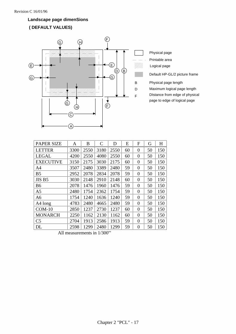
Landscape page dimenSions
( DEFAULT VALUES)
A
B
C
D
E
F
G HF
GH
E
G G
Physical page
Printable area
Logical page
Default HP-GL/2 picture frame
B Physical page length
D Maximum logical page length
F DIstance from edge of physical
page to edge of logical page
PAPER SIZE A B C D E F G HLETTER 3300 2550 3180 255060 0 50 150LEGAL 4200 2550 4080 2550 60 0 50 150EXECUTIVE 3150 2175 3030 2175 60 0 50 150A4 3507 2480 3389 2480 59 0 50 150B5 2952 2078 2834 2078 59 0 50 150JIS B5 3030 2148 2910 214860 0 50 150B6 2078 1476 1960 1476 59 0 50 150A5 2480 1754 2362 1754 59 0 50 150A6 1754 1240 1636 1240 59 0 50 150A4 long 4783 2480 4665 248059 0 50 150COM-10 2850 1237 2730 123760 0 50 150MONARCH 2250 1162 2130 116260 0 50 150C5 2704 1913 2586 191359 0 50 150DL 2598 1299 2480 1299 59 0 50 150
All measurements in 1/300'"
Revision C 16/01/96
Chapter 2 "PCL" - 18
CoordinatesThe printer control language coordinate system has its origin at the intersection of the left edge of the logical pageand the top margin. The x-coordinate value of the current cursor position increases as the cursor moves from leftto right, the y-coordinate value increases as the cursor moves down the page. The cursor can be explicitlypositioned anywhere on the current logical page using the PCL coordinate system. In addition, the cursor’scoordinate position will change as text and graphics are printed.
UnitsYou can specify cursor movement within the PCL coordinate system using one of three different unit systems.
Decipoints
A decipoint is one-tenth of a typographic point measurement = 1/720".
Rows and columns
Using the horizontal motion index (HMI) (Esc&k#H) and vertical motion index (VMI)(Esc&l#C) commands youcan set the width of a column and the height of a row. You can then use the column width and row height as theunits of the coordinate system. The line-spacing command is an alternative to the VMI command.
Units
A unit is the measurement which can be defined by the unit of measure command.
Unit of Measure
Esc&u#D (27)(38)(117)#(68) <1Bh><26h><75h>#<44h>
• # value can be 96, 100, 120, 144, 150, 160, 180, 200, 225, 240, 288, 300, 360, 400, 450, 480, 600, 720, 800,900, 1200, 1440, 1800, 2400, 3600, 7200.
• # stands for the unit of measurement in dots per inch.
• The value set by this command is used as the unit setting for use by other setting commands such as ESC*p#X.
• The default value of # is 300.
Example)Esc&u300D Esc*p+100x+200Y
move cursor 100/300 inch right and 200/300 inch down.Esc&u600D Esc*p+100x+200Y
move cursor 100/600 inch right and 200/600 inch down.
Revision C 16/01/96
Chapter 2 "PCL" - 19
Setting the left and right margins
Esc&a#L (27)(38)(97)#(76) <1Bh><26h><61h>#<4Ch>
# stands for the distance between the left edge of the logical page and the left margin in columns.
Esc&a#M (27)(38)(97)#(77) <1Bh><26h><61h>#<4Dh>
# stands for the distance between the left edge of the logical page and the right margin in columns.
• The column width is as defined by the HMI. If you subsequently change the HMI the margin positions that youhave set do not change - that is, when you specify margin positions they remain fixed physically until youspecify new ones or reset them to default values.
• You cannot specify a value for the left margin that is greater than the value of the current right margin.
• If the current cursor position is to the left of your new left margin setting, the cursor will be moved to the newleft margin.
• You cannot set the right margin to be further right than the right edge of the logical page.
• If the current cursor position is to the right of your new right margin setting, the cursor will be moved to thenew right margin.
• The factory default left and right margin settings are at the left and right edges of the logical page respectively.
• Depending on your model, margin settings can be made from the printer’s control panel (see the User Guide).
10 REM ***** SET AND CLEAR SIDE MARGINS *****20 ESC$=CHR$(27)30 WIDTH "LPT1:",25540 REM --- END OF LINE WRAP ON ---50 LPRINT ESC$+"&s0C";60 REM --- LEFT MARGIN SET TO 10 COLUMNS ----70 LPRINT ESC$+"&a10L";80 REM --- RIGHT MARGIN SET TO 70 COLUMNS ----90 LPRINT ESC$+"&a70M";100 REM --- PRINT "0123456789" 10 TIMES110 FOR I=1 TO 10120 LPRINT "0123456789";130 NEXT140 LPRINT150 REM --- CLEAR SIDE MARGIN ----160 LPRINT ESC$+"9";170 REM --- PRINT "0123456789" 10 TIMES180 FOR I=1 TO 10190 LPRINT "0123456789";200 NEXT210 REM --- PAPER EJECT ----220 LPRINT CHR$(12);230 END
Revision C 16/01/96
Chapter 2 "PCL" - 20
Resetting the horizontal margins
Esc9 (27)(39) <1Bh><39h>
• This command resets the left and right margins to the left and right edges of the logical page respectively.
Setting the top margin
Esc& ll#E (27)(38)(108)#(69) <1Bh><26h><6Ch>#<45h>
# stands for the distance between the top of the logical page and the top margin in rows.
• The row height is as defined by the VMI. If you subsequently change the VMI (or the line spacing) the topmargin position that you have set does not change - that is, when you specify the top margin position it remainsfixed physically until you specify a new one or reset it to a default value.
• The top margin command is ignored if you try to set a margin greater than the current length of the logicalpage.
• The top margin command is ignored if the current VMI is 0.
• The factory default top margin setting is half an inch below the top of the logical page.
• Depending on your model, the top margin can be set from the printer’s control panel (see the User Guide).
10 REM ******* SET TOP MARGIN TO 10 LINES *******20 REM30 ESC$=CHR$(27)40 LPRINT ESC$+"&l10E";50 LPRINT "10 LINES "60 LPRINT CHR$(12);70 END
Revision C 16/01/96
Chapter 2 "PCL" - 21
Setting the vertical motion index (VMI)
Esc& ll#C (27)(38)(108)#(67) <1Bh><26h><6Ch>#<43h>
# stands for the height of one row in 1/48".
• # can have any value in the range 0-32767.
• The distance specified by the VMI is the vertical distance moved down the page when the printer performs aline feed. The VMI is also sometimes referred to as the line pitch.
• If you try to set a VMI that is greater than the current length of the logical page the command is ignored.
• Changing the VMI setting does not affect the position of the top margin.
• The factory default setting is 8 - that is, the printer will print six lines of text per inch.
• Depending on your model, you can change the number of lines per page setting from the printer's controlpanel or remote printer console. If you change its setting, the VMI will change automatically.
10 REM ***** SETTING THE LINE PITCH *****20 ESC$=CHR$(27)30 REM40 REM --- SET LINE PITCH TO 1/48 INCH ---50 LPRINT ESC$+"&l1C";60 FOR I=1 TO 1070 LPRINT "I can't read."80 NEXT90 LPRINT ESC$+"&l8C";100 LPRINT110 LPRINT120 REM --- SET LINE PITCH TO 1/12 INCH ----130 LPRINT ESC$+"&l4C";140 LPRINT "line pitch is 1/12 inch"150 REM --- SET LINE PITCH TO 1/8 INCH ----160 LPRINT ESC$+"&l6C";170 LPRINT "line pitch is 1/8 inch"180 REM --- SET LINE PITCH TO 1/6 INCH ----190 LPRINT ESC$+"&l8C";200 LPRINT "line pitch is 1/6 inch"210 REM --- SET LINE PITCH TO 1/4 INCH ----220 LPRINT ESC$+"&l12C";230 LPRINT "line pitch is 1/4 inch"240 LPRINT "line pitch is 1/4 inch"250 REM --- PAPER EJECT ----260 LPRINT CHR$(12);270 END
< Sample file 1>
Revision C 16/01/96
Chapter 2 "PCL" - 22
Setting the horizontal motion index (HMI)
Esc&k#H (27)(38)(107)#(72) <1Bh><25h><6Bh>#<48h>
# stands for the width of one column in 1/120".
• # can have any value in the range 0-32767 and can have up to four decimal places.
• If you are using a fixed space font the HMI is the horizontal distance moved across the page when the printerprints one character.
• If you are using a proportionally spaced font the HMI is the horizontal distance moved across the page whenthe printer receives a space control code <20h>.
• If any font characteristics are changed, or a Select Primary Font or Select Secondary Font control code is sentto the printer, the HMI is set to correspond to the default pitch value of the newly selected font.
• Changing the HMI setting does not affect the positions of the left and right margins.
• The factory default setting is 12 - that is, the printer will print ten characters of fixed pitch text per inch.
10 REM ***** SETTING THE CHARACTER PITCH *****20 ESC$=CHR$(27)30 REM --- DEFAULT IS 10 CPI PITCH ---40 LPRINT "10 PITCH "50 REM --- SET 5 CPI PITCH ---60 LPRINT ESC$+"&k24H";70 LPRINT "AAA"80 REM --- SET 6 CPI PITCH ---90 LPRINT ESC$+"&k20H";100 LPRINT "AAA"110 REM --- SET 8 CPI PITCH ---120 LPRINT ESC$+"&k15H";130 LPRINT "AAA"140 REM --- SET 10 CPI PITCH ---150 LPRINT ESC$+"&k12H";160 LPRINT "AAA"170 REM --- SET 12 CPI PITCH ---180 LPRINT ESC$+"&k12H";190 LPRINT "AAA"200 REM --- SET 0 CPI PITCH ---210 LPRINT ESC$+"&kH";220 LPRINT "I CAN'T READ"230 REM --- PAPER EJECT ----240 LPRINT CHR$(12);250 END
< Sample file 2>
Revision C 16/01/96
Chapter 2 "PCL" - 23
Setting line spacing
Esc& ll#D (27)(38)(108)#(68) <1Bh><25h><6Ch>#<44h>
# stands for the number of lines to be printed per inch.
• # can have any of the following values: 1, 2, 3, 4, 6, 8, 12, 16, 24 or 48.
• This command performs the same function as the VMI command.
• Changing the line spacing setting does not affect the position of the top margin.
• The factory default setting is 6 - that is, the printer will print six lines of text per inch.
• Depending on your printer model, the number of lines per page can also be set from the printer’s control panelor remote printer console.
Text length
Esc& ll#F (27)(38)(108)#(70) <1Bh><25h><6Ch>#<46h>
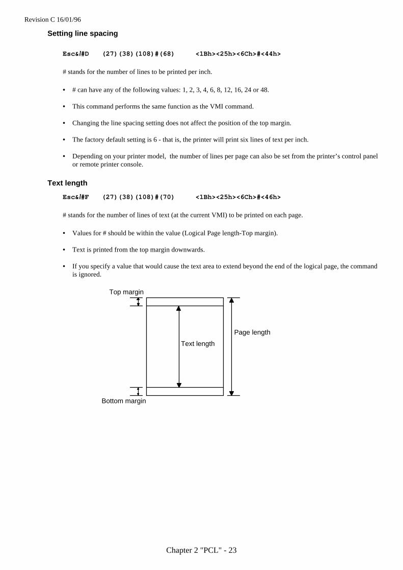
# stands for the number of lines of text (at the current VMI) to be printed on each page.
• Values for # should be within the value (Logical Page length-Top margin).
• Text is printed from the top margin downwards.
• If you specify a value that would cause the text area to extend beyond the end of the logical page, the commandis ignored.
Top margin
Bottom margin
Text length
Page length
Revision C 16/01/96
Chapter 2 "PCL" - 24
Page length
Esc& ll#P (27)(38)(108)#(80) <1Bh><25h><6Ch>#<50h>
# stands for the length of the logical page in lines (at the current VMI).
• If you specify a page length greater than is allowed by the physical size of the paper in the currently installedpaper tray, a control panel message prompts you to load paper of the appropriate size.
• When the printer receives this command any unprinted pages are printed, and the left, right and top margins,and the text length are set to their user defaults.
• If you specify a page length greater than is allowed by any of the supported paper sizes, the command isignored.
• If the current VMI is 0 the command is ignored.
• The factory default page size is letter, for which the default page length is 66 lines (11 inches with 6 lines perinch). The default lengths for the other paper sizes are: Legal - 84 lines, A4 - 70 lines, Executive - 63 lines (allat 6 lines per inch).
• Depending on your printer model, you can also set the page length from the printer’s control panel or remoteprinter console by setting LINES to the required number of lines per page in the PAGE FORMAT mode (seethe User Guide).
10 REM ******* SETTING THE PAGE LENGTH TO 66 LINES *******20 REM30 ESC$=CHR$(27)40 LPRINT ESC$+"&l66P";50 FOR I=1 TO 6760 LPRINT STR$(I)70 NEXT80 LPRINT CHR$(12);90 END
Perforation skip
You can set the printer to flow text from one page to the next when it encounters a line feed (or half line feed) thatwould otherwise move the cursor position to below the bottom of the text area. When perforation skip is enabledthe cursor is automatically moved to the top left hand corner of the text area on the next page and printingcontinues.
Esc& ll#L (27)(38)(108)#(76) <1Bh><25h><6Ch>#<4Ch>
# is either 0 or 1.
• # = 0 turns the perforation skip feature off.
• # = 1 turns the perforation skip feature on.
• The factory default mode is perforation skip on.
• Whenever the perforation skip mode is changed, the top margin and page length values are reset to theirdefault values.
Revision C 16/01/96
Chapter 2 "PCL" - 25
Positioning the cursor
You can position the cursor anywhere on the logical page. In addition, the cursor position is automaticallychanged when text or graphics are printed. You can either position the cursor using absolute PCL coordinatevalues or position it relative to the current cursor position, using dots, decipoints or rows and columns as units. Incase of using dots, the units value is defined by the ESC & u # d command. The commands for positioning thecursor are listed below.
Vertical positioning
Vertical cursor positioning in Rows
Esc&a#R (27)(38)(97)#(82) <1Bh><26h><61h>#<52h>
# = number of rows
• A plus or minus sign preceding the number of rows parameter indicates that the cursor is to be positionedrelative to its current position. A signed positive parameter value signifies that the cursor is to be repositionedvertically downwards on the page, a negative value means that it will be moved upwards.
• An unsigned number as the parameter signifies that the vertical repositioning is absolute - the cursor will berepositioned the specified number of rows below the top margin, the PCL coordinate system’s x-axis.
• The parameter value can have up to two decimal places.
• The cursor’s horizontal position remains unchanged.
• If you attempt to move the cursor to a position that is outside the boundaries of the logical page, the cursor willbe positioned at either the top or bottom of the logical page as appropriate.
Units
Esc*p#Y (27)(38)(112)#(89) <1Bh><26h><70h>#<79h>
# = number of units
• Units value is defined by the Esc & u # D command.
• A plus or minus sign preceding the number of dots parameter indicates that the cursor is to be positionedrelative to its current position. A signed positive parameter value signifies that the cursor is to be repositionedvertically downwards on the page, a negative value means that it will be moved upwards.
• An unsigned number as the parameter signifies that the vertical repositioning is absolute - the cursor will berepositioned the specified number of dots below the top margin, the PCL coordinate system’s x-axis.
• The cursor’s horizontal position remains unchanged.
• If you attempt to move the cursor to a position that is outside the boundaries of the logical page, the cursor willbe positioned at either the top or bottom of the logical page as appropriate.
Revision C 16/01/96
Chapter 2 "PCL" - 26
Vertical cursor positioning in Decipoints
Esc&a#V (27)(38)(97)#(86) <1Bh><26h><61h>#<56h>
# = number of decipoints in 1/720"
• A plus or minus sign preceding the number of decipoints parameter indicates that the cursor is to be positionedrelative to its current position. A signed positive parameter value signifies that the cursor is to be repositionedvertically downwards on the page, a negative value means that it will be moved upwards.
• An unsigned number as the parameter signifies that the vertical repositioning is absolute - the cursor will berepositioned the specified number of decipoints below the top margin, the PCL coordinate system’s x-axis.
• The cursor’s horizontal position remains unchanged.
• If you attempt to move the cursor to a position that is outside the boundaries of the logical page, the cursor willbe positioned at either the top or bottom of the logical page as appropriate.
Horizontal position
Horizontal cursor positioning in Columns
Esc&a#C (27)(38)(97)#(67) <1Bh><26h><61h>#<43h>
# = number of columns
• A plus or minus sign preceding the number of columns parameter indicates that the cursor is to be positionedrelative to its current position. A signed positive parameter value signifies that the cursor is to be repositionedto the right on the page, a negative value means that it will be moved to the left.
• An unsigned number as the parameter signifies that the horizontal repositioning is absolute - the cursor will berepositioned the specified number of columns to the right of the left edge of the logical page, the PCLcoordinate system’s y-axis.
• The parameter value can have up to two decimal places.
• The cursor’s vertical position remains unchanged.
• If you attempt to move the cursor to a position that is outside the boundaries of the logical page, the cursor willbe positioned at either the left or right edge of the logical page as appropriate.
10 REM ***** HORIZONTAL CURSOR POSITIONING *****20 ESC$=CHR$(27)30 REM40 REM --- POSITIONING CURSOR AT COLUMN 10 ---50 LPRINT ESC$+"&a10C";60 LPRINT "A";70 REM --- MOVING CURSOR 5 COLUMNS TO THE LEFT ---80 LPRINT ESC$+"&a-5C";90 LPRINT "B";100 REM --- MOVING CURSOR 10 COLUMNS TO THE RIGHT ---110 LPRINT ESC$+"&a+10C";120 LPRINT "C";130 REM --- PAPER EJECT ---140 LPRINT CHR$(12);150 END
< Sample file 3 >
Revision C 16/01/96
Chapter 2 "PCL" - 27
Units
Esc*p#X (27)(38)(112)#(88) <1Bh><26h><70h>#<58h>
# = number of units
• Units value is defined by the Esc & u # D command.
• A plus or minus sign preceding the number of dots parameter indicates that the cursor is to be positionedrelative to its current position. A signed positive parameter value signifies that the cursor is to be repositionedto the right on the page, a negative value means that it will be moved to the left.
• An unsigned number as the parameter signifies that the horizontal repositioning is absolute - the cursor will berepositioned the specified number of dots to the right of the left edge of the logical page, the PCL coordinatesystem’s y-axis.
• The cursor’s vertical position remains unchanged.
• If you attempt to move the cursor to a position that is outside the boundaries of the logical page, the cursor willbe positioned at either the left or right edge of the logical page as appropriate.
10 REM ***** HORIZONTAL CURSOR POSITIONING *****20 ESC$=CHR$(27)30 REM40 REM --- POSITIONING CURSOR AT 1 INCH ---50 LPRINT ESC$+"*p300X";60 LPRINT "A";70 REM --- MOVING CURSOR 0.5 INCHES TO THE LEFT ---80 LPRINT ESC$+"*p-150X";90 LPRINT "B";100 REM --- MOVING CURSOR 1 INCH TO THE RIGHT ---110 LPRINT ESC$+"*p+300X";120 LPRINT "C";130 REM --- PAPER EJECT ---140 LPRINT CHR$(12);150 END
< Sample file 4 >
Revision C 16/01/96
Chapter 2 "PCL" - 28
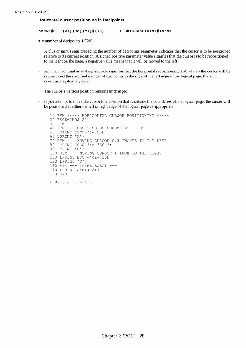
Horizontal cursor positioning in Decipoints
Esc&a#H (27)(38)(97)#(72) <1Bh><26h><61h>#<48h>
# = number of decipoints 1/720"
• A plus or minus sign preceding the number of decipoints parameter indicates that the cursor is to be positionedrelative to its current position. A signed positive parameter value signifies that the cursor is to be repositionedto the right on the page, a negative value means that it will be moved to the left.
• An unsigned number as the parameter signifies that the horizontal repositioning is absolute - the cursor will berepositioned the specified number of decipoints to the right of the left edge of the logical page, the PCLcoordinate system’s y-axis.
• The cursor’s vertical position remains unchanged.
• If you attempt to move the cursor to a position that is outside the boundaries of the logical page, the cursor willbe positioned at either the left or right edge of the logical page as appropriate.
10 REM ***** HORIZONTAL CURSOR POSITIONING *****20 ESC$=CHR$(27)30 REM40 REM --- POSITIONING CURSOR AT 1 INCH ---50 LPRINT ESC$+"&a720H";60 LPRINT "A";70 REM --- MOVING CURSOR 0.5 INCHES TO THE LEFT ---80 LPRINT ESC$+"&a-360H";90 LPRINT "B";100 REM --- MOVING CURSOR 1 INCH TO THE RIGHT ---110 LPRINT ESC$+"&a+720H";120 LPRINT "C";130 REM --- PAPER EJECT ---140 LPRINT CHR$(12);150 END
< Sample file 5 >
Revision C 16/01/96
Chapter 2 "PCL" - 29
Positioning the cursor using control codes
The carriage return, space, horizontal tab and backspace control codes can also be used to reposition the cursorusing the current VMI and HMI settings.
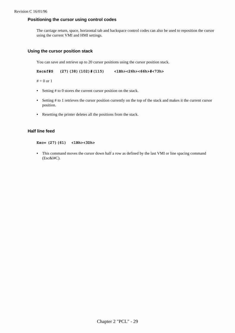
Using the cursor position stack
You can save and retrieve up to 20 cursor positions using the cursor position stack.
Esc&f#S (27)(38)(102)#(115) <1Bh><26h><66h>#<73h>
# = 0 or 1
• Setting # to 0 stores the current cursor position on the stack.
• Setting # to 1 retrieves the cursor position currently on the top of the stack and makes it the current cursorposition.
• Resetting the printer deletes all the positions from the stack.
Half line feed
Esc= (27)(61) <1Bh><3Dh>
• This command moves the cursor down half a row as defined by the last VMI or line spacing command(Esc&l#C).

Revision C 16/01/96
Chapter 2 "PCL" - 30
Logical page orientation
Esc& ll#O (27)(38)(108)#(79) <1Bh><26h><6Ch>#<4Fh>
# = 0, 1, 2 or 3
• This command sets the orientation of the logical page relative to the physical page.
• Values of # produce orientations as follows: 0 = portrait, 1 = landscape, 2=reverse portrait and 3 = reverselandscape.
• Sending this command to the printer causes the page length, text length, top, left and right margins to be set totheir user default values. Any previously transmitted data is printed out and the cursor is positioned at the topleft hand corner of the text area on the next page.
• Portrait or landscape orientation can also be selected from the printer’s control panel.
• The factory default orientation is portrait.
(0,0)
(0,0)
(0,0)
(0,0)
"TEXT"
X
Y
X
X
X
Y
Y
Y
Portrait Landscape
Reverse portrait Reverse landscape
Top margin
Physical page
Logical page
Top margin
Logical page
Physical page
# = 0 # = 1
# = 2 # = 3
Revision C 16/01/96
Chapter 2 "PCL" - 31
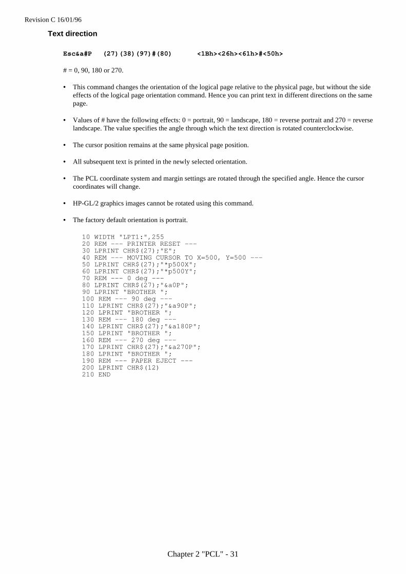
Text direction
Esc&a#P (27)(38)(97)#(80) <1Bh><26h><61h>#<50h>
# = 0, 90, 180 or 270.
• This command changes the orientation of the logical page relative to the physical page, but without the sideeffects of the logical page orientation command. Hence you can print text in different directions on the samepage.
• Values of # have the following effects: 0 = portrait, 90 = landscape, 180 = reverse portrait and 270 = reverselandscape. The value specifies the angle through which the text direction is rotated counterclockwise.
• The cursor position remains at the same physical page position.
• All subsequent text is printed in the newly selected orientation.
• The PCL coordinate system and margin settings are rotated through the specified angle. Hence the cursorcoordinates will change.
• HP-GL/2 graphics images cannot be rotated using this command.
• The factory default orientation is portrait.
10 WIDTH "LPT1:",25520 REM --- PRINTER RESET ---30 LPRINT CHR$(27);"E";40 REM --- MOVING CURSOR TO X=500, Y=500 ---50 LPRINT CHR$(27);"*p500X";60 LPRINT CHR$(27);"*p500Y";70 REM --- 0 deg ---80 LPRINT CHR$(27);"&a0P";90 LPRINT "BROTHER ";100 REM --- 90 deg ---110 LPRINT CHR$(27);"&a90P";120 LPRINT "BROTHER ";130 REM --- 180 deg ---140 LPRINT CHR$(27);"&a180P";150 LPRINT "BROTHER ";160 REM --- 270 deg ---170 LPRINT CHR$(27);"&a270P";180 LPRINT "BROTHER ";190 REM --- PAPER EJECT ---200 LPRINT CHR$(12)210 END
Revision C 16/01/96
Chapter 2 "PCL" - 32
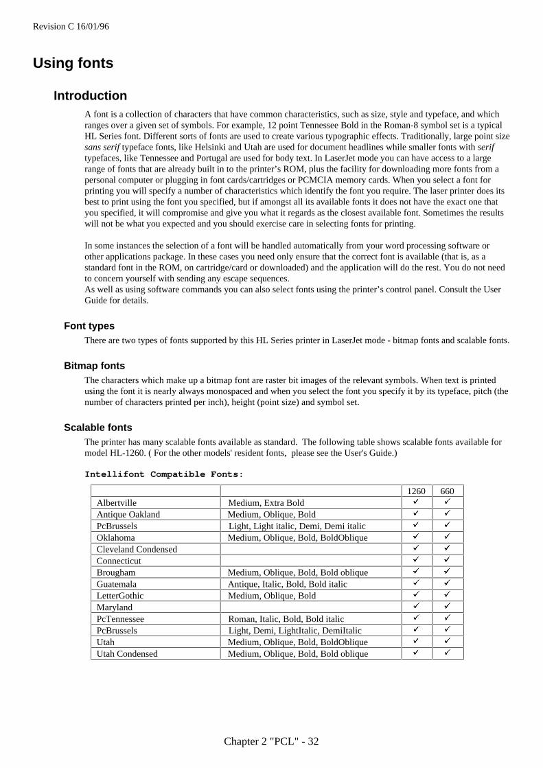
Using fonts
IntroductionA font is a collection of characters that have common characteristics, such as size, style and typeface, and whichranges over a given set of symbols. For example, 12 point Tennessee Bold in the Roman-8 symbol set is a typicalHL Series font. Different sorts of fonts are used to create various typographic effects. Traditionally, large point sizesans serif typeface fonts, like Helsinki and Utah are used for document headlines while smaller fonts with seriftypefaces, like Tennessee and Portugal are used for body text. In LaserJet mode you can have access to a largerange of fonts that are already built in to the printer’s ROM, plus the facility for downloading more fonts from apersonal computer or plugging in font cards/cartridges or PCMCIA memory cards. When you select a font forprinting you will specify a number of characteristics which identify the font you require. The laser printer does itsbest to print using the font you specified, but if amongst all its available fonts it does not have the exact one thatyou specified, it will compromise and give you what it regards as the closest available font. Sometimes the resultswill not be what you expected and you should exercise care in selecting fonts for printing.
In some instances the selection of a font will be handled automatically from your word processing software orother applications package. In these cases you need only ensure that the correct font is available (that is, as astandard font in the ROM, on cartridge/card or downloaded) and the application will do the rest. You do not needto concern yourself with sending any escape sequences.As well as using software commands you can also select fonts using the printer’s control panel. Consult the UserGuide for details.
Font typesThere are two types of fonts supported by this HL Series printer in LaserJet mode - bitmap fonts and scalable fonts.
Bitmap fontsThe characters which make up a bitmap font are raster bit images of the relevant symbols. When text is printedusing the font it is nearly always monospaced and when you select the font you specify it by its typeface, pitch (thenumber of characters printed per inch), height (point size) and symbol set.
Scalable fontsThe printer has many scalable fonts available as standard. The following table shows scalable fonts available formodel HL-1260. ( For the other models' resident fonts, please see the User's Guide.)
Intellifont Compatible Fonts:
1260 660Albertville Medium, Extra Bold ü ü
Antique Oakland Medium, Oblique, Bold ü ü
PcBrussels Light, Light italic, Demi, Demi italic ü ü
Oklahoma Medium, Oblique, Bold, BoldOblique ü ü
Cleveland Condensed ü ü
Connecticut ü ü
Brougham Medium, Oblique, Bold, Bold oblique ü ü
Guatemala Antique, Italic, Bold, Bold italic ü ü
LetterGothic Medium, Oblique, Bold ü ü
Maryland ü ü
PcTennessee Roman, Italic, Bold, Bold italic ü ü
PcBrussels Light, Demi, LightItalic, DemiItalic ü ü
Utah Medium, Oblique, Bold, BoldOblique ü ü
Utah Condensed Medium, Oblique, Bold, Bold oblique ü ü
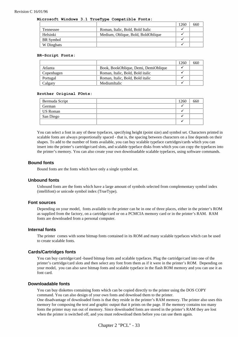
Revision C 16/01/96
Chapter 2 "PCL" - 33
Microsoft Windows 3.1 TrueType Compatible Fonts:
1260 660Tennessee Roman, Italic, Bold, Bold Italic ü
Helsinki Medium, Oblique, Bold, BoldOblique ü
BR Symbol ü
W Dingbats ü
BR-Script Fonts:
1260 660Atlanta Book, BookOblique, Demi, DemiOblique ü
Copenhagen Roman, Italic, Bold, Bold italic ü
Portugal Roman, Italic, Bold, Bold italic ü
Calgary MediumItalic ü
Brother Original FOnts:
Bermuda Script 1260 660German ü
US Roman ü
San Diego ü
ü
You can select a font in any of these typefaces, specifying height (point size) and symbol set. Characters printed inscalable fonts are always proportionally spaced - that is, the spacing between characters on a line depends on theirshapes. To add to the number of fonts available, you can buy scalable typeface cartridges/cards which you caninsert into the printer’s cartridge/card slots, and scalable typeface disks from which you can copy the typefaces intothe printer’s memory. You can also create your own downloadable scalable typefaces, using software commands.
Bound fontsBound fonts are the fonts which have only a single symbol set.
Unbound fontsUnbound fonts are the fonts which have a large amount of symbols selected from complementary symbol index(intellifont) or unicode symbol index (TrueType).
Font sourcesDepending on your model, fonts available to the printer can be in one of three places, either in the printer’s ROMas supplied from the factory, on a cartridge/card or on a PCMCIA memory card or in the printer’s RAM. RAMfonts are downloaded from a personal computer.
Internal fontsThe printer comes with some bitmap fonts contained in its ROM and many scalable typefaces which can be usedto create scalable fonts.
Cards/Cartridges fontsYou can buy cartridge/card -based bitmap fonts and scalable typefaces. Plug the cartridge/card into one of theprinter’s cartridge/card slots and then select any font from them as if it were in the printer’s ROM. Depending onyour model, you can also save bitmap fonts and scalable typeface in the flash ROM memory and you can use it asfont card.
Downloadable fontsYou can buy diskettes containing fonts which can be copied directly to the printer using the DOS COPYcommand. You can also design of your own fonts and download them to the printer.One disadvantage of downloaded fonts is that they reside in the printer’s RAM memory. The printer also uses thismemory for composing the text and graphic output that it prints on the page. If the memory contains too manyfonts the printer may run out of memory. Since downloaded fonts are stored in the printer’s RAM they are lostwhen the printer is switched off, and you must redownload them before you can use them again.
Revision C 16/01/96
Chapter 2 "PCL" - 34
Primary and secondary fontsThe printer maintains two sets of font characteristics which define its primary and secondary fonts. The primaryfont is the one it will use by default, the secondary font can be selected instead. This facility enables you to havetwo parallel font definitions that you can switch between easily without invoking long escape sequences. You canselect the primary and secondary fonts using PCL commands.Depending on your model, you can also set any available fonts to be the printer’s user default primary andsecondary fonts using the printer’s control panel. Refer to the User Guide for instructions on how to do this.The factory default settings for both primary and secondary fonts are Brougham 12 point, 10 cpi Roman 8.Specifying the primary fontWhen you specify primary font characteristics you send escape codes with ‘(’ as the second character of thesequence. This tells the printer that the font characteristic you are specifying applies to the primary font.
Specifying the secondary fontWhen you specify secondary font characteristics you send escape codes with ‘)’ as the second character of thesequence. This tells the printer that the font characteristic you are specifying applies to the secondary font.
Selecting the default fontsTo set the primary font settings to those of the printers default font and discard all the software settings you havemade in the meantime, send the printer the following escape sequence:
Esc(3@ (27)(40)(51)(64) <1Bh><28h><33h><40h>
To set the secondary font settings to those of the printers default font send:
Esc)3@ (27)(41)(51)(64) <1Bh><29h><33h><40h>
Switching between the primary and secondary fontsTo select the primary font as the font for printing send the printer the SI control code:
SI (15) (0F)
To select the secondary font as the font for printing send the printer the SO control code:
SO (14) (0E)
Criteria for font selectionThe printer will try to match your stated font requirements as best it can with the fonts available to it in the threefont locations. In most cases you will be specifying a font you know to be present in one of the locations and theresulting printed text will appear exactly as you envisaged. However, if you specify a particular combination offont characteristics that is not possible, the printer will produce the closest possible match that it can by satisfyingthe following specifications in the order: the symbol set, spacing type, pitch (for monospaced fonts), the height,the stroke weight and the style. The meanings of each of these are explained in the following sub-sections.Likewise, if you simply specify a font attribute that is not available, for example if you request a Utah Light fontwhen only Utah Medium and Utah Bold are available in the font locations, the printer will simply ignore therequirement (light stroke weight, in this case) that it cannot fulfill.
Symbol setThe symbol set is the list of symbols that constitute a particular font. Normally symbol sets contain lower andupper case letters, numbers, punctuation marks and a selection of other commonly used symbols. Some symbol setsare designed for specific needs, for example, for generating text with mathematical expressions. The symbol sethas the highest priority of all the characteristics you specify when you designate the font you require. If the symbolset you choose is available, but not in conjunction with any of the other characteristics you specify, the printer willsatisfy your symbol set request at the expense of the rest of your designation and the text printed out may well lookcompletely different from what you expected to see.
Revision C 16/01/96
Chapter 2 "PCL" - 35
Symbol collectionsThe symbol collections contain many symbols and a symbol set is made from symbol collections by selecting therequired symbols for unbound fonts. As symbol collections have more symbols than symbol sets, unbound fontscan have more symbols than bound fonts. Due to the compatibility between symbol sets and symbol collections,the printer searches the designated MSL or Unicode number by using a symbol set mapping table.
Type of character spacingCharacter spacing is either fixed (monospacing), in which every printed character is allocated the same amount ofspace on the line, or proportional, where characters are spaced according to their shape and size. For any serioustypographic work proportional spacing is essential since fixed spacing is unattractive and hard to read. In generalmonospacing is used with bitmap fonts, and proportional spacing is used with scalable fonts. However,proportionally spaced bitmap fonts do exist.
PitchPitch is the number of characters that are printed per inch and therefore only applies to monospaced fonts. If youmake a pitch selection while using a proportionally spaced font the command will have no immediate effect.However, the new pitch will be stored as part of the primary (or secondary) font designation and applied the nexttime a monospaced font is selected as the primary (or secondary) font.The printer’s in-built bitmap fonts all have a pitch of either 10, 12 or 16.66 characters per inch.
HeightHeight refers to the height in points (1/72") of unaccented capital letters in a font. This is the generally acceptedmethod of defining the height of a font’s characters. Scaled fonts can be specified to an accuracy of 0.25 points.
StyleA font’s style is defined by its posture (upright or italic), width (condensed, normal or expanded) and structure(solid, outline or shadow). Upright and italic bitmap fonts and scalable typefaces are available in the printer’sROM. However, these are all normal and solid fonts. To print using any of the other styles (for example, usingCondensed Helsinki, or Outline Tennessee) you would have to download the requisite font or install a fontcard/cartridge containing it.
Stroke weightStroke weight refers to the thickness of the lines which make up the printed characters. Characters of normal linethickness are called medium. Thicker lines are referred to as bold or black and thinner lines as light or thin. Youcan specify 15 different stroke weights - 0 denotes medium weight, negative values signify thinner strokes, andpositive values signify bolder (thicker) strokes. If you have the bold font available that matches your fontdesignation, a stroke weight selection of 1 to 7 will produce bold text. Likewise, for light or thin text you wouldneed to make the requisite light or thin font available for the stroke weight selection to have any effect.
TypefaceTypeface refers to the designed style of the characters. Commonly known typefaces include Times, Helvetica,Univers and Palatino. The printer has its own resident typefaces. When selecting a particular typeface ensure thatit meets all your other specified criteria, otherwise the printer will substitute a font of a different typeface that cansatisfy the other, higher priority criteria, such as style and stroke weight.
Revision C 16/01/96
Chapter 2 "PCL" - 36
Font selection commands
User-defined symbol sets
User-defined symbol sets can be used with Unbound scalable fonts. Three new commands below are prepared foruser-defined symbol set.
To define a symbol set, its ID code must be defined at first.Next, a list of symbols for the symbol set must be downloaded.Then, you can use the defined ID code for symbol set selection.
Symbol Set ID Code Command
Esc*c#R (27)(42)(99)#(82) <1Bh><2Ah><63h>#<52h>
• Value for # can be from 0 to 2047.
• This command defines the ID code for a user-defined symbol set which can be used to control symbol setselection.
• The symbol set ID code defined by this command must be calculated by using the following formula.
Symbol Set ID Code = ( # x 32 ) + ( ID - 64 )
Symbol set selection values consists of numerical character(s) and alphabetical character.For example, 8U is the symbol set selection value for Roman-8. In this case, the Symbol set ID codeis 277 as the result of the following calculation.
(8 x 32 ) + (85 - 64) = 277
• Make sure to select an unused number for a new ID code that you define. If the ID code has been usedalready, the printer deletes the existing symbol set and defines the new symbol set.
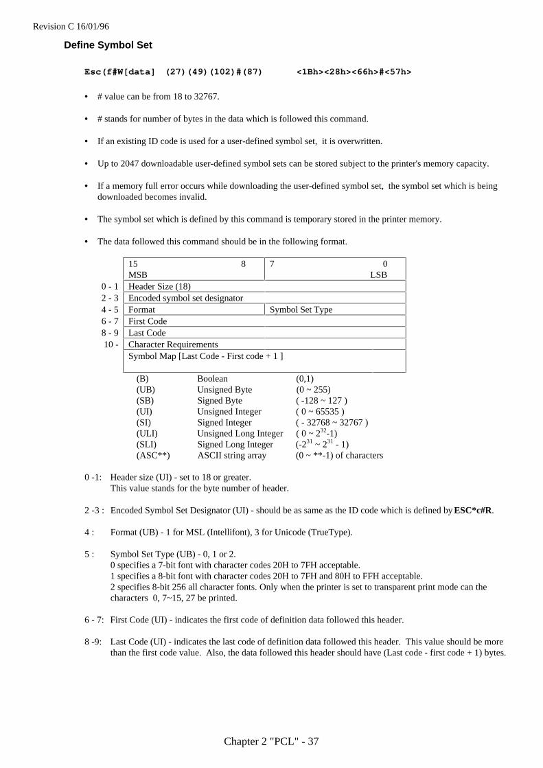
Revision C 16/01/96
Chapter 2 "PCL" - 37
Define Symbol Set
Esc(f#W[data] (27)(49)(102)#(87) <1Bh><28h><66h>#<57h>
• # value can be from 18 to 32767.
• # stands for number of bytes in the data which is followed this command.
• If an existing ID code is used for a user-defined symbol set, it is overwritten.
• Up to 2047 downloadable user-defined symbol sets can be stored subject to the printer's memory capacity.
• If a memory full error occurs while downloading the user-defined symbol set, the symbol set which is beingdownloaded becomes invalid.
• The symbol set which is defined by this command is temporary stored in the printer memory.
• The data followed this command should be in the following format.
15 8MSB
7 0 LSB
0 - 1 Header Size (18)2 - 3 Encoded symbol set designator4 - 5 Format Symbol Set Type6 - 7 First Code8 - 9 Last Code10 - Character Requirements
Symbol Map [Last Code - First code + 1 ]
(B) Boolean (0,1)(UB) Unsigned Byte (0 ~ 255)(SB) Signed Byte ( -128 ~ 127 )(UI) Unsigned Integer ( 0 ~ 65535 )(SI) Signed Integer ( - 32768 ~ 32767 )(ULI) Unsigned Long Integer ( 0 ~ 232-1)(SLI) Signed Long Integer (-231 ~ 231 - 1)(ASC**) ASCII string array (0 ~ **-1) of characters
0 -1: Header size (UI) - set to 18 or greater.This value stands for the byte number of header.
2 -3 : Encoded Symbol Set Designator (UI) - should be as same as the ID code which is defined by ESC*c#R.
4 : Format (UB) - 1 for MSL (Intellifont), 3 for Unicode (TrueType).
5 : Symbol Set Type (UB) - 0, 1 or 2.0 specifies a 7-bit font with character codes 20H to 7FH acceptable.1 specifies a 8-bit font with character codes 20H to 7FH and 80H to FFH acceptable.2 specifies 8-bit 256 all character fonts. Only when the printer is set to transparent print mode can thecharacters 0, 7~15, 27 be printed.
6 - 7: First Code (UI) - indicates the first code of definition data followed this header.
8 -9: Last Code (UI) - indicates the last code of definition data followed this header. This value should be morethan the first code value. Also, the data followed this header should have (Last code - first code + 1) bytes.
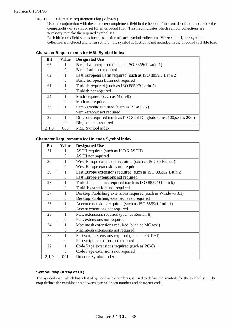
Revision C 16/01/96
Chapter 2 "PCL" - 38
10 - 17: Character Requirement Flag ( 8 bytes )Used in conjunction with the character complement field in the header of the font descriptor, to decide thecompatibility of a symbol set for an unbound font. This flag indicates which symbol collections arenecessary to make the required symbol set.Each bit in this field stands for the selection of each symbol collection. When set to 1, the symbolcollection is included and when set to 0, the symbol collection is not included in the unbound scalable font.
Character Requirements for MSL Symbol index
Bit Value Designated Use63 1
0Basic Latin required (such as ISO 8859/1 Latin 1)Basic Latin not required
62 10
East European Latin required (such as ISO 8859/2 Latin 2)Basic European Latin not required
61 10
Turkish required (such as ISO 8859/9 Latin 5)Turkish not required
34 10
Math required (such as Math-8)Math not required
33 10
Semi-graphic required (such as PC-8 D/N)Semi-graphic not required
32 10
Dingbats required (such as ITC Zapf Dingbats series 100,series 200 )Dingbats not required
2,1,0 000 MSL Symbol index
Character Requirements for Unicode Symbol index
Bit Value Designated Use31 1
0ASCII required (such as ISO 6 ASCII)ASCII not required
30 10
West Europe extensions required (such as ISO 69 French)West Europe extensions not required
29 10
East Europe extensions required (such as ISO 8859/2 Latin 2)East Europe extensions not required
28 10
Turkish extensions required (such as ISO 8859/9 Latin 5)Turkish extensions not required
27 10
Desktop Publishing extensions required (such as Windows 3.1)Desktop Publishing extensions not required
26 10
Accent extensions required (such as ISO 8859/1 Latin 1)Accent extentions not required
25 10
PCL extensions required (such as Roman-8)PCL extensions not required
24 10
Macintosh extensions required (such as MC text)Macintosh extensions not required
23 10
PostScript extensions required (such as PS Text)PostScript extensions not required
22 10
Code Page extensions required (such as PC-8)Code Page extensions not required
2,1,0 001 Unicode Symbol Index
Symbol Map (Array of UI )
The symbol map, which has a list of symbol index numbers, is used to define the symbols for the symbol set. Thismap defines the combination between symbol index number and character code.
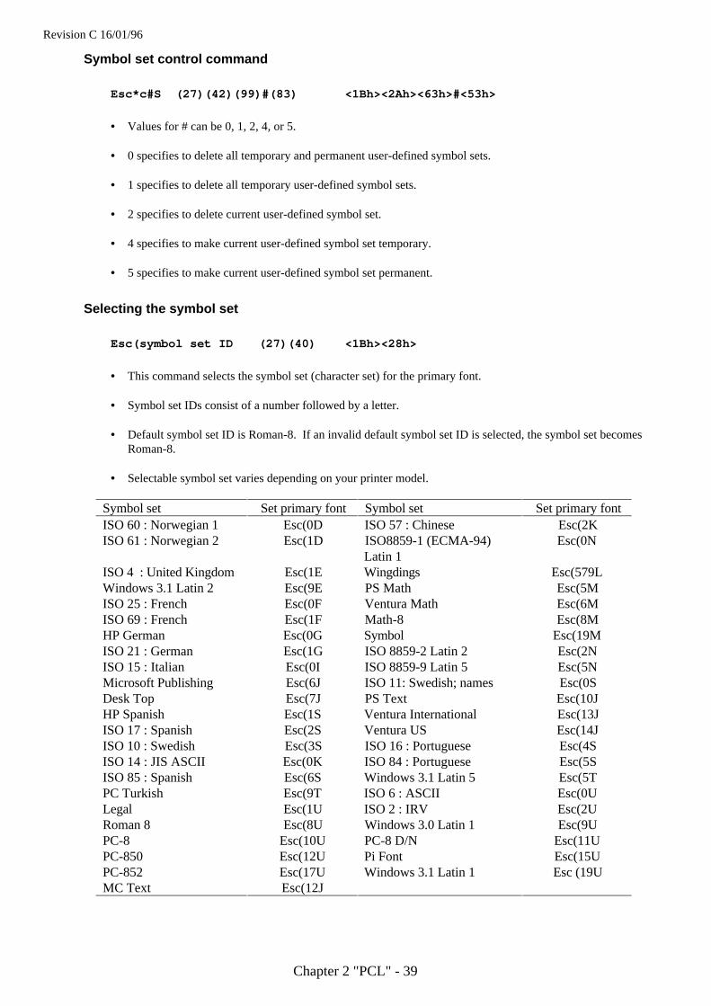
Revision C 16/01/96
Chapter 2 "PCL" - 39
Symbol set control command
Esc*c#S (27)(42)(99)#(83) <1Bh><2Ah><63h>#<53h>
• Values for # can be 0, 1, 2, 4, or 5.
• 0 specifies to delete all temporary and permanent user-defined symbol sets.
• 1 specifies to delete all temporary user-defined symbol sets.
• 2 specifies to delete current user-defined symbol set.
• 4 specifies to make current user-defined symbol set temporary.
• 5 specifies to make current user-defined symbol set permanent.
Selecting the symbol set
Esc(symbol set ID (27)(40) <1Bh><28h>
• This command selects the symbol set (character set) for the primary font.
• Symbol set IDs consist of a number followed by a letter.
• Default symbol set ID is Roman-8. If an invalid default symbol set ID is selected, the symbol set becomesRoman-8.
• Selectable symbol set varies depending on your printer model.
Symbol set Set primary font Symbol set Set primary fontISO 60 : Norwegian 1 Esc(0D ISO 57 : Chinese Esc(2KISO 61 : Norwegian 2 Esc(1D ISO8859-1 (ECMA-94)
Latin 1Esc(0N
ISO 4 : United Kingdom Esc(1E Wingdings Esc(579LWindows 3.1 Latin 2 Esc(9E PS Math Esc(5MISO 25 : French Esc(0F Ventura Math Esc(6MISO 69 : French Esc(1F Math-8 Esc(8MHP German Esc(0G Symbol Esc(19MISO 21 : German Esc(1G ISO 8859-2 Latin 2 Esc(2NISO 15 : Italian Esc(0I ISO 8859-9 Latin 5 Esc(5NMicrosoft Publishing Esc(6J ISO 11: Swedish; names Esc(0SDesk Top Esc(7J PS Text Esc(10JHP Spanish Esc(1S Ventura International Esc(13JISO 17 : Spanish Esc(2S Ventura US Esc(14JISO 10 : Swedish Esc(3S ISO 16 : Portuguese Esc(4SISO 14 : JIS ASCII Esc(0K ISO 84 : Portuguese Esc(5SISO 85 : Spanish Esc(6S Windows 3.1 Latin 5 Esc(5TPC Turkish Esc(9T ISO 6 : ASCII Esc(0ULegal Esc(1U ISO 2 : IRV Esc(2URoman 8 Esc(8U Windows 3.0 Latin 1 Esc(9UPC-8 Esc(10U PC-8 D/N Esc(11UPC-850 Esc(12U Pi Font Esc(15UPC-852 Esc(17U Windows 3.1 Latin 1 Esc (19UMC Text Esc(12J

Revision C 16/01/96
Chapter 2 "PCL" - 40
User-defined symbol sets are available for the HL-10h, HL-1260 and HL-660. They are defined by the commandESC ( f # W.
Esc)symbol set ID (27)(41) <1Bh><29h>
• This command selects the symbol set (character set) for the secondary font.
• To select any of the above symbol sets for the secondary font simply substitute ‘)’ for ‘(’ in the commandshown in the table.
10 REM ****** SELECT A CHARACTER SET ******20 ESC$=CHR$(27)30 WIDTH "LPT1:",25540 REM --- ROMAN-8 CHARACTER SET SELECTION ------50 LPRINT ESC$+"(8U";60 REM --- PRINT CHARACTERS ----70 FOR I=160 TO 25580 LPRINT CHR$(I);90 NEXT100 LPRINT110 REM --- PC-8 CHARACTER SET SELECTION ------120 LPRINT ESC$+"(10U";130 REM --- PRINT CHARACTERS ----140 FOR I=160 TO 255150 LPRINT CHR$(I);160 NEXT170 LPRINT180 REM --- PAPER EJECT ---190 LPRINT CHR$(12);200 END
There is a further group of symbol sets that are available for Brother fonts only. You can select these as follows:
Esc(s#C (27)(40)(115)#(67) <1Bh><28h><73h>#<43h>
• This command selects the symbol set (character set) for the primary font.
Esc)s#C (27)(41)(115)#(67) <1Bh><29h><73h>#<43h>
• This command selects the symbol set (character set) for the secondary font.
• Brother symbol set IDs consist of a number only.
Symbol Set Set primary font Symbol set Set primary fontRoman-8 Esc(s1C Portuguese Esc(s15CUS ASCII Esc(s2C Swiss German Esc(s16CGerman Esc(s3C American Spanish Esc(s17CUK English Esc(s4C Norwegian/Danish Esc(s18CFrench Esc(s5C Canadian Esc(s19CDutch Esc(s6C Finnish/Swedish Esc(s20CItalian Esc(s7C South African Esc(s21CS. Spanish Esc(s8C PC-8 D/N Esc(s23CA. English WP Esc(s9C PC-8 Esc(s25CUK ASCII/2 Esc(s10C PC-850 Esc(s26CSymbol Esc(s11C PC-860 Esc(s27CInternational Esc(s12C PC-863 Esc(s28CAmerican English Esc(s13C PC-865 Esc(s29CUK ASCII Esc(s14C Japanese English Esc(s38C

Revision C 16/01/96
Chapter 2 "PCL" - 41
• To select any of the above symbol sets for the secondary font simply substitute ‘)’ for ‘(’ in the commandshown in the table.
10 REM ****** SELECTING CHARACTER SETS ******20 ESC$=CHR$(27)30 WIDTH "LPT1:",25540 REM --- GERMAN CHARACTER SET SELECTION ------50 LPRINT ESC$+"(s3C";60 REM --- PRINT CHARACTERS ----70 FOR I=33 TO 12780 LPRINT CHR$(I);90 NEXT100 LPRINT110 REM --- FRENCH CHARACTER SET SELECTION ------120 LPRINT ESC$+"(s5C";130 REM --- PRINT CHARACTERS ----140 FOR I=33 TO 127150 LPRINT CHR$(I);160 NEXT170 LPRINT180 REM --- PAPER EJECT ---190 LPRINT CHR$(12);200 END
Selecting the type of character spacing
Esc(s#P (27)(40)(115)#(80) <1Bh><28h><73h>#<50h>
• This command selects the spacing type for the primary font.
Esc)s#P (27)(41)(115)#(80) <1Bh><29h><73h>#<50h>
• This command selects the spacing type for the secondary font.
• • # = 0 selects fixed spacing and # = 1 selects proportional spacing.
10 REM ****** SELECTING A PROPORTIONAL OR FIXED SPACE FONT ******20 ESC$=CHR$(27)30 WIDTH "LPT1:",25540 REM --- SELECT A PROPORTIONALLY SPACED FONT ----50 LPRINT ESC$+"(s1P";60 FOR I=33 TO 12770 LPRINT CHR$(I);80 NEXT90 LPRINT100 REM --- SELECT A FIXED SPACE FONT ---110 LPRINT ESC$+"(s0P";120 FOR I=33 TO 127130 LPRINT CHR$(I);140 NEXT150 LPRINT160 REM --- PAPER EJECT ---170 LPRINT CHR$(12);180 END
Revision C 16/01/96
Chapter 2 "PCL" - 42
Selecting the pitch
Esc(s#H (27)(40)(115)#(72) <1Bh><28h><73h>#<48h>
• This command designates the pitch for the primary font.
Esc)s#H (27)(41)(115)#(72) <1Bh><29h><73h>#<48h>
• This command designates the pitch for the secondary font.
• # = the number of characters to be printed per inch. However, the actual size range is defined in combinationwith the character height.
• The printer’s in-built bitmap fonts all have a pitch of either 10, 12 or 16.66 characters per inch, and you canspecify any of these as follows:
Esc&k0S ( 10 cpi )
Esc&k2S ( 16.66 cpi )
Esc&k4S ( 12 cpi )
• The selection will apply to whichever font you are currently specifying (primary or secondary).
• If the printer doesn't have the specified size of font, the next largest size of font is used. If the printer doesn'thave a larger sized font, the next smallest one is used.
• This value is ignored by the printer when a proportional spaced font is selected.
10 REM ****** CHARACTER PITCH SELECTION ******20 ESC$=CHR$(27)30 WIDTH "LPT1:",25540 REM --- SELECT A 10 CPI PITCH FONT ----50 LPRINT ESC$+"(s10H";60 FOR I=33 TO 12770 LPRINT CHR$(I);80 NEXT90 LPRINT100 REM --- SELECT A 12 CPI PITCH FONT ---110 LPRINT ESC$+"(s12H";120 FOR I=33 TO 127130 LPRINT CHR$(I);140 NEXT150 LPRINT160 REM --- PAPER EJECT ---170 LPRINT CHR$(12);180 END
Selecting the height
Esc(s#V (27)(40)(115)#(86) <1Bh><28h><73h>#<56h>
• This command designates the height of the primary font.
Esc)s#V (27)(41)(115)#(86) <1Bh><29h><73h>#<56h>
• This command designates the height of the secondary font.
• # is the size in points (1/72") from 0.25 to 999.75 in 0.25 increments.
• This value is ignored by the printer when a fixed-spaced scalable font is selected.

Revision C 16/01/96
Chapter 2 "PCL" - 43
Scaling the scalable fonts vertically or horizontally
EscCR!#H (27)(13)(33)#(72) <1Bh><0Dh><21h>#<48h>
• This command designates the height of the scalable fonts.
EscCR!#V (27)(13)(33)#(86) <1Bh><0Dh><21h>#<56h>
• This command designates the width of the scalable fonts.
• # can be from 0.25 ~ 3.00 in 0.01 increments.
• # value is set to 0.25 when # is specified less than 0.25, and # value is set to 3.00 when # is specified biggerthan 3.00.
• The value set by this command is initialized when the emulation change, Resetting, Test Printing, or Macrooverlay is executed.
Selecting the style
Esc(s#S (27)(40)(115)#(83) <1Bh><28h><73h>#<53h>
• This command designates the style of the primary font.
Esc)s#S (27)(41)(115)#(83) <1Bh><29h><73h>#<53h>
• This command designates the style of the secondary font.
• If you select a particular style (for example upright condensed outline) the command will only take effect if thefont is available in one of the three font locations.
Value Font Style01458243264128160
Upright & solidItalicCondensedCondensed italicCompressed, or extra condensedExpandedOutlineInlineShadowedOutline shadowed
10 REM ****** PRINT IN ITALIC & UPRIGHT STYLE ******20 ESC$=CHR$(27)30 WIDTH "LPT1:",25540 REM --- PRINT USING AN ITALIC FONT ----50 LPRINT ESC$+"(s1S";60 REM --- PRINT FONT ----70 FOR I=33 TO 12780 LPRINT CHR$(I);90 NEXT100 LPRINT110 REM --- PRINT USING AN UPRIGHT FONT ---120 LPRINT ESC$+"(s0S";130 REM --- PRINT FONT ----140 FOR I=33 TO 127150 LPRINT CHR$(I);160 NEXT170 LPRINT180 REM -- PAPER EJECT ---190 LPRINT CHR$(12);200 END

Revision C 16/01/96
Chapter 2 "PCL" - 44
Selecting the stroke weight
Esc(s#B (27)(40)(115)#(66) <1Bh><28h><73h>#<42h>
• This command designates the stroke weight of the primary font.
Esc)s#B (27)(41)(115)#(66) <1Bh><29h><73h>#<42h>
• This command designates the stroke weight of the secondary font
• # is an integer between –7 and 7. A value of 0 signifies a medium stroke weight, negative numbers signify thinor light stroke weights and positive numbers signify bold stroke weights.
• If you select a light or bold stroke weight the command will only have an effect if the font is available in one ofthe three font locations.
Selecting the typeface
Esc(s#T (27)(40)(115)#(84) <1Bh><28h><73h>#<54h>
• This command designates the typeface of the primary font.
Esc)s#T (27)(41)(115)#(84) <1Bh><29h><73h>#<54h>
• This command designates the typeface of the secondary font.
• If the typeface you specify is not available in any of the three font source locations the printer will substitute afont of a different typeface.
• The available values vary with the printer model. The following table shows the value for each typeface andavailability.
Typeface Set primary font Set secondary font 6V 10V 10h 660 1260Albertville Esc(s4362T Esc)s4362T * * *Antique Oakland Esc(s4168T Esc)s4168T * * *Brougham Esc(s4099T Esc)s4099T * * *Cleveland Condensed Esc(s4140T Esc)s4140T * * *Connecticut Esc(s4116T Esc)s4116T * * *Guatemala Antique Esc(s4197T Esc)s4197T * * *LetterGothic Esc(s4102T Esc)s4102T * * *Maryland Esc(s4297T Esc)s4297T * * *Oakland Esc(s4113T Esc)s4113T * * *PC Brussels Esc(s4143T Esc)s4143T * * * * *PC Tennessee Esc(s4101T Esc)s4101T * * * * *Utah Esc(s4148T Esc)s4148T * * * * *
BR Symbol Esc(s16686T Esc)s16686T * * *Helsinki Esc(s16602T Esc)s16602T * * *Tennessee Esc(s16901T Esc)s16901T * * *W Dingbats Esc(s31402T Esc)s31402T * * *
Atlanta Esc(s155T Esc)s155T * *Calgary Esc(s159T Esc)s159T * *Copenhagen Esc(s157T Esc)s157T * *Portugal Esc(s158T Esc)s158T * *
Letter Gothic16.66 Esc(s130T Esc)s130T * * * * *Brougham Esc(s128T Esc)s128T * *OCR-A Esc(s104T Esc)s104T * * *
Revision C 16/01/96
Chapter 2 "PCL" - 45
OCR-B Esc(s110T Esc)s110T * * *
Bermuda Script Esc(s134T Esc)s134T *Germany Esc(s132T Esc)s132T *San Diego Esc(s133T Esc)s133T *US Roman Esc(s135T Esc)s135T *
Font orientationThe printer’s built-in fonts are all portrait fonts. If you switch the orientation of the logical page to landscape andselect a font, the printer will automatically create the landscape font in its memory. This saves you having to makethe landscape font available by installing a card/cartridge or by downloading the font, but takes up printer memoryand may cause the printer to run out of space when trying to compose complex page layouts.
Transparent print data
Esc&p#X (character codes)(27)(38)(112)#(88) <1Bh><26h><70h>#<58h>
• This command enables you to print characters which are normally unprintable.
• # is the number of bytes of data that follow the command.
• Each byte of data is interpreted as a character code and the corresponding character in the currently selectedsymbol set is printed (if there is one). You can use this command to print the symbols in the character setwhich do not appear on the keyboard.
• If there is no character in the current symbol set corresponding to a specified code, a space is printed.
• The command is useful when using character sets like the IBM All Character Set in which every single codehas a corresponding character.
• Any control codes within the data will have no effect. The control code byte is treated as a character code.
Underlining text
Esc&d#D (27)(38)(100)#(68) <1Bh><26h><64h>#<44h>
• This command enables the underline facility.
• This command disables the underline facility.
• # is either 0 or 3. A value of 0 signifies fixed underlining, 3 specifies floating underlining.
• Fixed underlining means that the underline is drawn in the same place for all the characters of a particularfont.
• Floating underlining means that the underline is drawn in the same place for all the characters on a particularline.
Esc&d@ (27)(38)(100)(64) <1Bh><26h><64h><40h>

Revision C 16/01/96
Chapter 2 "PCL" - 46
Downloadable font manipulationFonts that you have bought on diskette can be downloaded to the printer from diskette or hard disk using the DOSCOPY command or a font downloading applications program. To create your own fonts you can use PCLcommands to send the various blocks of data that comprise a downloadable font. There are also a number of PCLcommands that enable you to manage fonts that you have already downloaded (both those that you have boughtand those you may have created yourself).If you are using commercially available fonts consult the documentation that came with them for information onhow best to send them to the printer.
Font ID
Esc&*c#D (27)(38)(42)(99)#(68) <1Bh><26h><2Ah><63h>#<44h>
• • This command identifies the numerical ID of the font on which subsequent operations will be performed.
• # is the font ID number.
• Use this command to specify the ID number of a font that you are about to download, or of a font already inprinter memory that you want to perform a particular operation on it.
• If you specify the number of a font that already exists in memory and then download a new font from yourcomputer, the new font will overwrite the original font and assume the ID number that you specified.
Operations on downloaded fonts
Esc*c#F (27)(38)(42)(99)#(70) <1Bh><26h><2Ah><63h>#<46h>
• This command performs an operation on one or more downloaded fonts.
• # identifies the operation to be performed.
• # = 0 Delete all downloaded fonts from the printer’s memory.
• # = 1 Delete all temporary fonts from the printer’s memory.(Fonts can be made permanent so as to be saved when the printer is reset - see below).
• # = 2 Delete the font (whose ID number was most recently specified) from the printer’s memory.
• # = 3 Delete the character (whose character code was most recently specified) from the font (whose ID numberwas most recently specified).
(The command for specifying a character code is given in the section entitled Creating DownloadableFonts).
• # = 4 Make the font (whose ID number was most recently specified) temporary
• If # = 5 Make the font (whose ID number was most recently specified) permanent
• If # = 6 Make/Assign a copy of the current font (primary or secondary) with the last specified ID number.
• If # = 1026 Delete the font (whose ID number was most recently specified) from the installed PCMCIA card.
• If # = 1028 Delete all download fonts in the installed PCMCIA card
• If # = 1029 Save the font (whose ID number was most recently specified) into the installed PCMCIA card.(All download fonts on PCMCIA card are permanent fonts.)
• #=1026, 1028, 1029 is available only when the PCMCIA memory card is installed to HL-1260 & HL-10h.
Revision C 16/01/96
Chapter 2 "PCL" - 47
Selecting a downloaded font
Esc(#X (27)(40)#(88) <1Bh><28h>#<58h>
• This command selects a downloaded font as the primary font.
Esc)#X (27)(41)#(88) <1Bh><29h>#<58h>
• This command selects a downloaded font as the secondary font.
• # is the ID number of the downloaded font.
Creating downloadable fonts
DownloadingYou can download existing fonts (that is, ones that you have bought or ones that you have created previously)using either a font downloading application program or the DOS command
COPY/b <filename> PRN
In addition, some word-processing and DeskTop publishing programs will automatically download the fonts thathave been used in a document when that document is printed.Alternatively, you can create a new downloadable font and download the necessary blocks of data that comprisethe downloadable font using PCL commands.
To send a font, you must send* a font descriptor block followed by the character code* a character descriptor* data for each character
The printer can download 3 types of fonts.Bitmapped fonts, Bound Scalable fonts, and Unbound scalable fonts.
Sending the font descriptor
Esc)s#W (font descriptor data) (27)(40)(115)#(58) <1Bh><28h><73h>#<88h>
• This command sends the font descriptor to the printer.
• # should be in the range 0 to 32767.
• # is the number of bytes in the descriptor.
• Characters are designed on a notional grid known as the character cell. The positioning and shape of eachcharacter on the grid defines its size, shape and alignment to the other characters in the font.
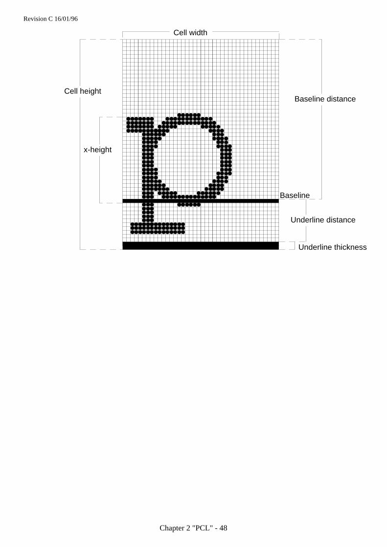
Revision C 16/01/96
Chapter 2 "PCL" - 48
Cell height
x-height
Baseline distance
Underline distance
Baseline
Underline thickness
Cell width
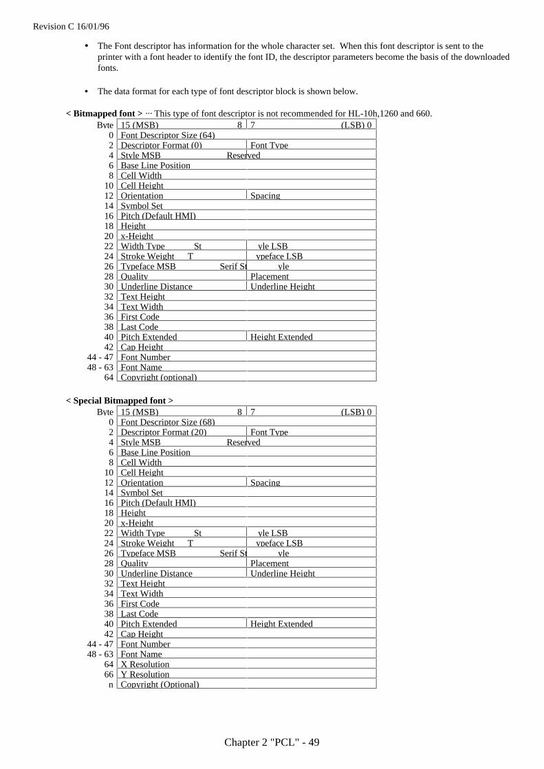
Revision C 16/01/96
Chapter 2 "PCL" - 49
• The Font descriptor has information for the whole character set. When this font descriptor is sent to theprinter with a font header to identify the font ID, the descriptor parameters become the basis of the downloadedfonts.
• The data format for each type of font descriptor block is shown below.
< Bitmapped font > ··· This type of font descriptor is not recommended for HL-10h,1260 and 660.Byte 15 (MSB) 87 (LSB) 0
0 Font Descriptor Size (64)2 Descriptor Format (0) Font Type4 Style MSB Reserved6 Base Line Position8 Cell Width
10 Cell Height12 Orientation Spacing14 Symbol Set16 Pitch (Default HMI)18 Height20 x-Height22 Width Type St yle LSB24 Stroke Weight T ypeface LSB26 Typeface MSB Serif St yle28 Quality Placement30 Underline Distance Underline Height32 Text Height34 Text Width36 First Code38 Last Code40 Pitch Extended Height Extended42 Cap Height
44 - 47 Font Number48 - 63 Font Name
64 Copyright (optional)
< Special Bitmapped font >Byte 15 (MSB) 87 (LSB) 0
0 Font Descriptor Size (68)2 Descriptor Format (20) Font Type4 Style MSB Reserved6 Base Line Position8 Cell Width
10 Cell Height12 Orientation Spacing14 Symbol Set16 Pitch (Default HMI)18 Height20 x-Height22 Width Type St yle LSB24 Stroke Weight T ypeface LSB26 Typeface MSB Serif St yle28 Quality Placement30 Underline Distance Underline Height32 Text Height34 Text Width36 First Code38 Last Code40 Pitch Extended Height Extended42 Cap Height
44 - 47 Font Number48 - 63 Font Name
64 X Resolution66 Y Resolutionn Copyright (Optional)
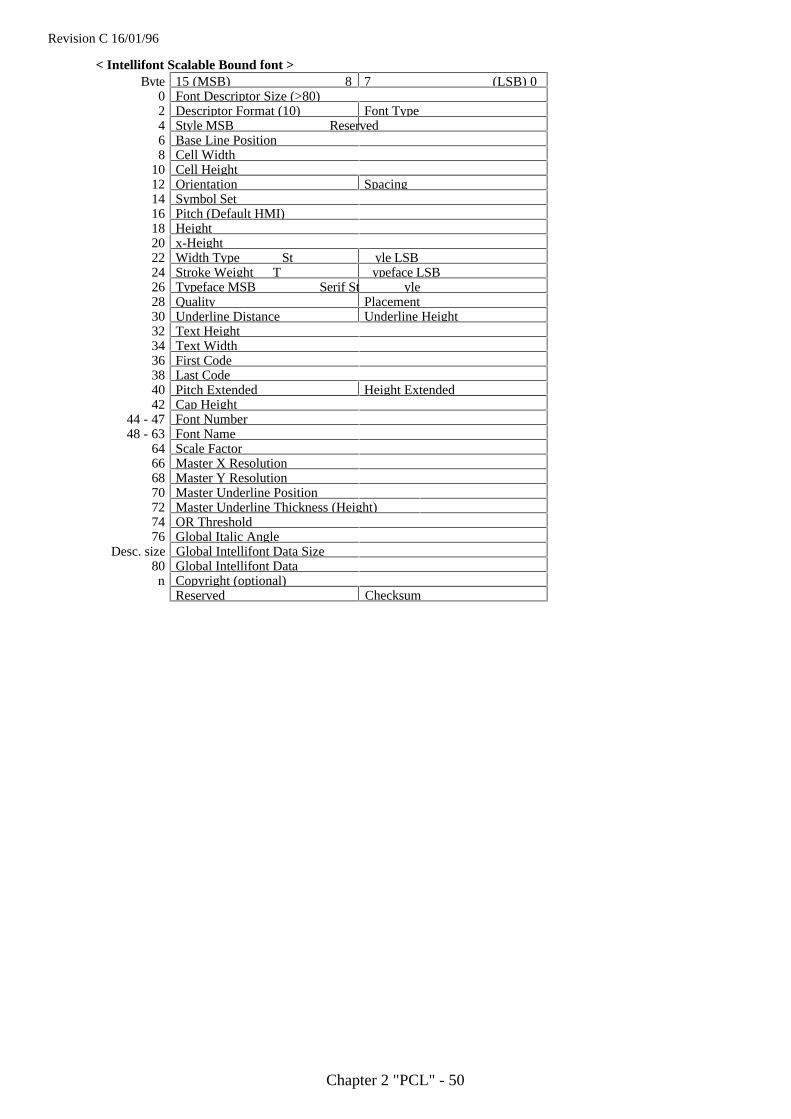
Revision C 16/01/96
Chapter 2 "PCL" - 50
< Intellifont Scalable Bound font >Byte 15 (MSB) 87 (LSB) 0
0 Font Descriptor Size (>80)2 Descriptor Format (10) Font Type4 Style MSB Reserved6 Base Line Position8 Cell Width
10 Cell Height12 Orientation Spacing14 Symbol Set16 Pitch (Default HMI)18 Height20 x-Height22 Width Type St yle LSB24 Stroke Weight T ypeface LSB26 Typeface MSB Serif St yle28 Quality Placement30 Underline Distance Underline Height32 Text Height34 Text Width36 First Code38 Last Code40 Pitch Extended Height Extended42 Cap Height
44 - 47 Font Number48 - 63 Font Name
64 Scale Factor66 Master X Resolution68 Master Y Resolution70 Master Underline Position72 Master Underline Thickness (Height)74 OR Threshold76 Global Italic Angle
Desc. size Global Intellifont Data Size80 Global Intellifont Datan Copyright (optional)
Reserved Checksum
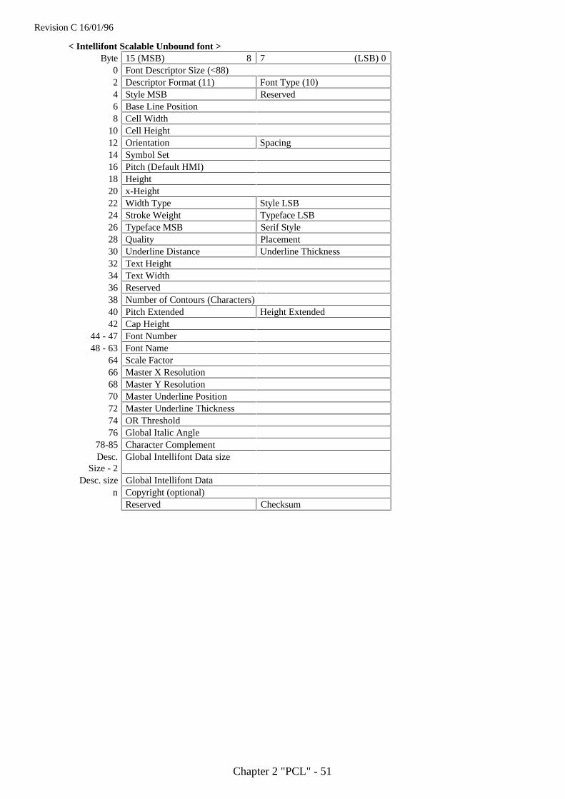
Revision C 16/01/96
Chapter 2 "PCL" - 51
< Intellifont Scalable Unbound font >Byte 15 (MSB) 8 7 (LSB) 0
0 Font Descriptor Size (<88)2 Descriptor Format (11) Font Type (10)4 Style MSB Reserved6 Base Line Position8 Cell Width
10 Cell Height12 Orientation Spacing14 Symbol Set16 Pitch (Default HMI)18 Height20 x-Height22 Width Type Style LSB24 Stroke Weight Typeface LSB26 Typeface MSB Serif Style28 Quality Placement30 Underline Distance Underline Thickness32 Text Height34 Text Width36 Reserved38 Number of Contours (Characters)40 Pitch Extended Height Extended42 Cap Height
44 - 47 Font Number48 - 63 Font Name
64 Scale Factor66 Master X Resolution68 Master Y Resolution70 Master Underline Position72 Master Underline Thickness74 OR Threshold76 Global Italic Angle
78-85 Character ComplementDesc.
Size - 2Global Intellifont Data size
Desc. size Global Intellifont Datan Copyright (optional)
Reserved Checksum
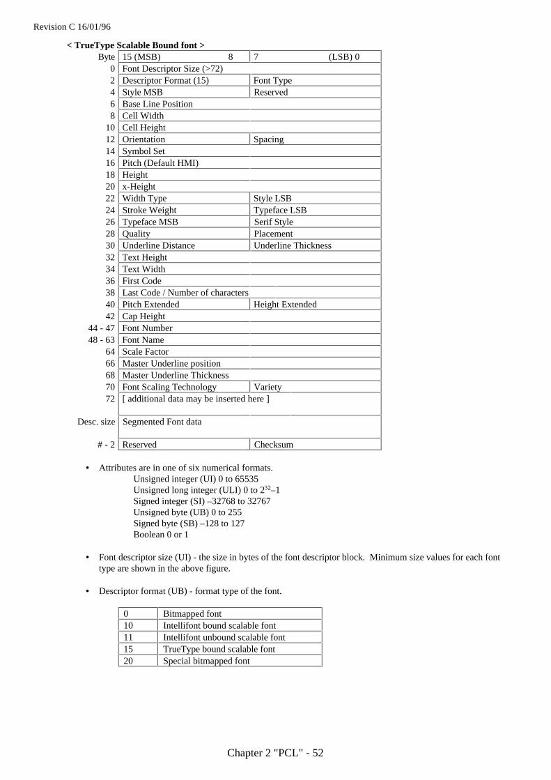
Revision C 16/01/96
Chapter 2 "PCL" - 52
< TrueType Scalable Bound font >Byte 15 (MSB) 8 7 (LSB) 0
0 Font Descriptor Size (>72)2 Descriptor Format (15) Font Type4 Style MSB Reserved6 Base Line Position8 Cell Width
10 Cell Height12 Orientation Spacing14 Symbol Set16 Pitch (Default HMI)18 Height20 x-Height22 Width Type Style LSB24 Stroke Weight Typeface LSB26 Typeface MSB Serif Style28 Quality Placement30 Underline Distance Underline Thickness32 Text Height34 Text Width36 First Code38 Last Code / Number of characters40 Pitch Extended Height Extended42 Cap Height
44 - 47 Font Number48 - 63 Font Name
64 Scale Factor66 Master Underline position68 Master Underline Thickness70 Font Scaling Technology Variety72 [ additional data may be inserted here ]
Desc. size Segmented Font data
# - 2 Reserved Checksum
• Attributes are in one of six numerical formats.Unsigned integer (UI) 0 to 65535Unsigned long integer (ULI) 0 to 232–1Signed integer (SI) –32768 to 32767Unsigned byte (UB) 0 to 255Signed byte (SB) –128 to 127Boolean 0 or 1
• Font descriptor size (UI) - the size in bytes of the font descriptor block. Minimum size values for each fonttype are shown in the above figure.
• Descriptor format (UB) - format type of the font.
0 Bitmapped font10 Intellifont bound scalable font11 Intellifont unbound scalable font15 TrueType bound scalable font20 Special bitmapped font

Revision C 16/01/96
Chapter 2 "PCL" - 53
• Font type (UB) - specifies type of symbol set.
0 Bound font. A 7-bit font with character codes 20H to 7FH acceptable.
1 Bound font. A 8-bit font with character codes 20H to 7FH and 80H to FFH acceptable.
2 Bound font. 8-bit all character codes are printable. However, 00H, 07H to 0FH and 1BH are printableonly when the data is defined as transparent print data.
10 Unbound font. Character codes corresponding to MSL numbers are acceptable.
11 Unbound font. Character codes corresponding to Unicode numbers are acceptable.
When a 7-bit font or 8-bit font is selected, it is possible for codes 00H to FFH to load characters or deletethem. It is also possible to print the characters if they are defined as transparent print data.
• Style MSB (UW) - combined with the Style LSB to make the style word. The value of the style word iscalculated as follows: style word = posture + (4 width) + (32 structure).
Value Posture0 Upright1 Italic2 Alternate Italic3 Reserved
Value Width0 Normal1 Condensed2 Compressed or Extra Condensed3 Extra compressed4 Ultra compressed5 Reserved6 Extended or Expanded7 Extra Extended or Extra Expanded
Value Structure
0 Solid1 Outline2 In-line3 Contour4 Solid with Shadow5 Outline with Shadow6 Inline with Shadow7 Contour with Shadow
8-11 Patterned (Complex patterns, subject to type family )12-15 Patterned with Shadow
16 Inverse17 Inverse in Open Border
18-30 Reserved31 Unknown structure
The reserved bits should be set to Zero.
• Baseline position (UI) -
Bitmap font - the height in dots from the top of the character cell to the baseline. The units of dots isthe same as the defined font resolution. This number can be in the range 0 to (cellheight - 1).
Intellifont scalable - a Ycoordinate in the design cell.TrueType scalable - the height in dots from the top of the character cell to the baseline. This should be set to
0.
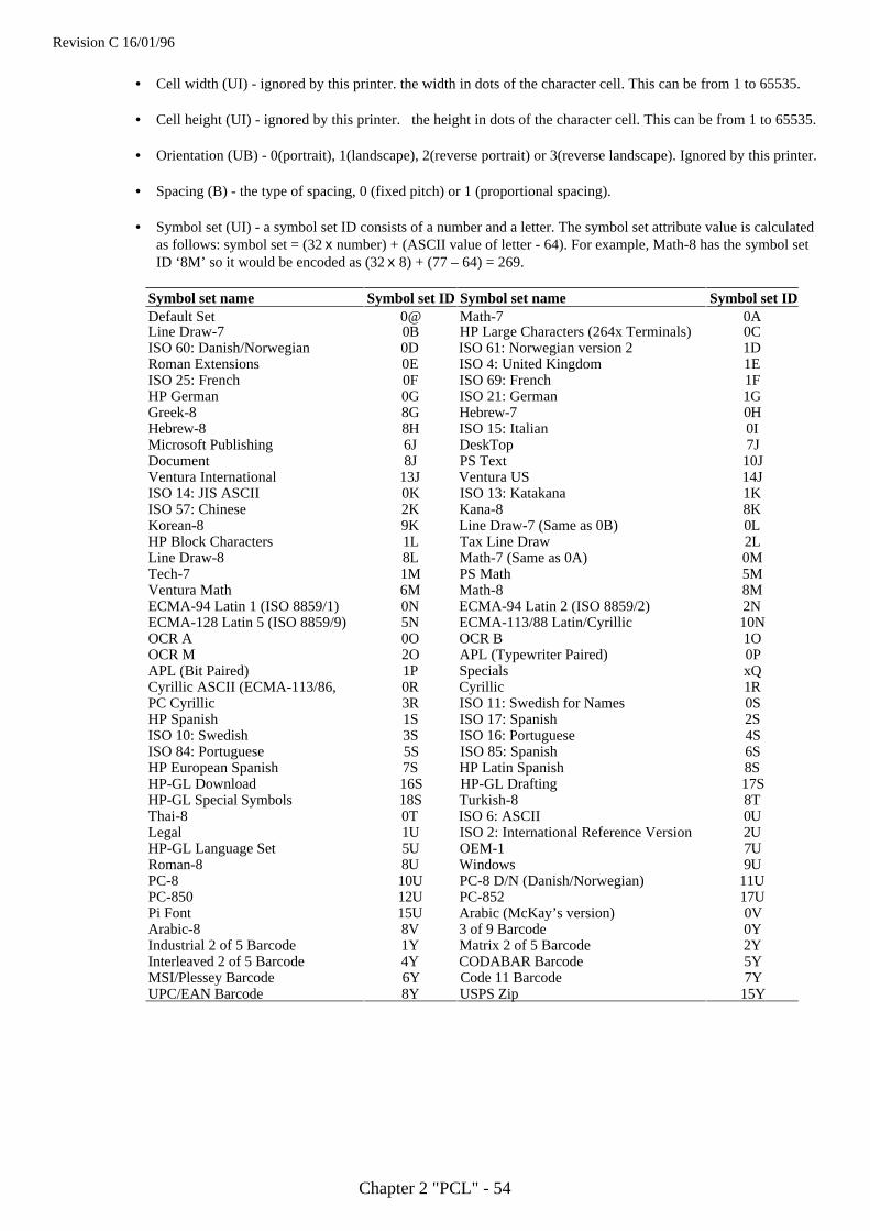
Revision C 16/01/96
Chapter 2 "PCL" - 54
• Cell width (UI) - ignored by this printer. the width in dots of the character cell. This can be from 1 to 65535.
• Cell height (UI) - ignored by this printer. the height in dots of the character cell. This can be from 1 to 65535.
• Orientation (UB) - 0(portrait), 1(landscape), 2(reverse portrait) or 3(reverse landscape). Ignored by this printer.
• Spacing (B) - the type of spacing, 0 (fixed pitch) or 1 (proportional spacing).
• Symbol set (UI) - a symbol set ID consists of a number and a letter. The symbol set attribute value is calculatedas follows: symbol set = (32 x number) + (ASCII value of letter - 64). For example, Math-8 has the symbol setID ‘8M’ so it would be encoded as (32 x 8) + (77 – 64) = 269.
Symbol set name Symbol set ID Symbol set name Symbol set IDDefault Set 0@ Math-7 0ALine Draw-7 0B HP Large Characters (264x Terminals) 0CISO 60: Danish/Norwegian 0D ISO 61: Norwegian version 2 1DRoman Extensions 0E ISO 4: United Kingdom 1EISO 25: French 0F ISO 69: French 1FHP German 0G ISO 21: German 1GGreek-8 8G Hebrew-7 0HHebrew-8 8H ISO 15: Italian 0IMicrosoft Publishing 6J DeskTop 7JDocument 8J PS Text 10JVentura International 13J Ventura US 14JISO 14: JIS ASCII 0K ISO 13: Katakana 1KISO 57: Chinese 2K Kana-8 8KKorean-8 9K Line Draw-7 (Same as 0B) 0LHP Block Characters 1L Tax Line Draw 2LLine Draw-8 8L Math-7 (Same as 0A) 0MTech-7 1M PS Math 5MVentura Math 6M Math-8 8MECMA-94 Latin 1 (ISO 8859/1) 0N ECMA-94 Latin 2 (ISO 8859/2) 2NECMA-128 Latin 5 (ISO 8859/9) 5N ECMA-113/88 Latin/Cyrillic 10NOCR A 0O OCR B 1OOCR M 2O APL (Typewriter Paired) 0PAPL (Bit Paired) 1P Specials xQCyrillic ASCII (ECMA-113/86, 0R Cyrillic 1RPC Cyrillic 3R ISO 11: Swedish for Names 0SHP Spanish 1S ISO 17: Spanish 2SISO 10: Swedish 3S ISO 16: Portuguese 4SISO 84: Portuguese 5S ISO 85: Spanish 6SHP European Spanish 7S HP Latin Spanish 8SHP-GL Download 16S HP-GL Drafting 17SHP-GL Special Symbols 18S Turkish-8 8TThai-8 0T ISO 6: ASCII 0ULegal 1U ISO 2: International Reference Version 2UHP-GL Language Set 5U OEM-1 7URoman-8 8U Windows 9UPC-8 10U PC-8 D/N (Danish/Norwegian) 11UPC-850 12U PC-852 17UPi Font 15U Arabic (McKay’s version) 0VArabic-8 8V 3 of 9 Barcode 0YIndustrial 2 of 5 Barcode 1Y Matrix 2 of 5 Barcode 2YInterleaved 2 of 5 Barcode 4Y CODABAR Barcode 5YMSI/Plessey Barcode 6Y Code 11 Barcode 7YUPC/EAN Barcode 8Y USPS Zip 15Y

Revision C 16/01/96
Chapter 2 "PCL" - 55
• Pitch (UI) - This value defines the default spacing for each point size in 1/4 dots. Combined with PitchExtended to specify the pitch of the font in 1/1024 dots. This is available for fixed pitch font charactersincluding the space character, and the space character of proportional spacing fonts.
For example, in case of a 17 cpi font (at 600 dpi),
= 141.176461 inch 600 dpi 4
17 chara. 1 inch 1
the value of Pitch (UI) should be 141.The remainder of 0.17646 is calculated as pitch extended:
0.17646 256
4 1 = 45.17376
the value for pitch extended is 45.
For Intellifont-scalable fonts only, the default HMI is calculated as follows.
Default HMI (in dots) = (300 x master design pitch x required point size) ÷{Master x Resolution ÷(height x 8)}
Default HMI ( in dots ) =(300 x master design pitch x required point size) ÷ {72.307 x scale factor}
• Height (UI) - specifies the height of the font in 1/4 dots. Combined with Height Extended to specify the heightof the font in 1/1024 dots. This value can be converted to the point size (1/72").For example, in case of a 10 point font at 300 dpi,
10 point72
1
1 inch
300 dots1 dots
4= 166.667
This value is normally set to 2000 for Intellifont and should be set to zero for TrueType fonts.
• x-height (UI) - ignored by this HL Series printer. This word specifies the height (for Bit mapped fonts) or thedistance from the baseline (for Scalable fonts) of a lower case ‘x’ in 1/4 dots.
• Width type (SB) - ignored by this HL Series printer. This byte specifies the fonts character width according tothe table below.
Value Width type–5 Ultra compressed–4 Extra compressed–3 Compressed or Extra condensed–2 Condensed0 Normal2 Expanded3 Extra expanded
• Style LSB (UB) - see Style MSB.

Revision C 16/01/96
Chapter 2 "PCL" - 56
• Stroke weight (SB) - valid values are from –7 to +7. 0 denotes the normal (Roman) stroke width, –7 is thelightest possible stroke and 7 is the boldest.
Value Stroke Weight–7 Ultra thin–6 Extra thin–5 Thin–4 Extra light–3 Light–2 Demi light–1 Semi light0 Medium, Book, or Text1 Semi bold2 Demi bold3 Bold4 Extra bold5 Black6 Extra black7 Ultra black
• Typeface family (UB) – the typeface. This word is made up of the Typeface MSB and the Typeface LSB andidentifies the typeface by number.Bits 0 to 11 specify the typeface family and bits 12 to 15 specify the vending company.
15 12 11 0
Vendor Typeface Family
Value Vendor0 Reserved1 Agfa Division, Miles Inc.2 Bitstream Inc.3 Linotype Company4 The Monotype Corporation plc5 Adobe Systems Inc.
The Typeface family number can be 0 to 4095. This value is calculated as follows;(TrueType base value) + (Vendor value x 4096) = Typeface Family
<Previous Models>The typeface word consists of four fields. Bits 0 to 8 specify the typeface family, bits 9 to 10 indicate theversion number, bits 11 to 14 identify the vending company, and bit 15 is always set to zero.
15
Vendor0 Version Typeface Base Value
11 10 9 8 0
• Serif style (UB) -Bitmapped font - ignored by this printer.Scalable font - values for the lower 6 bits are ignored and values for the upper 2 bits indicates the serif style.Bit 6 indicates sans serif and bit 7 indicates serif.
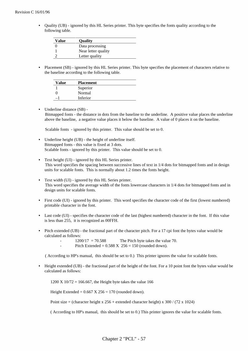
Revision C 16/01/96
Chapter 2 "PCL" - 57
• Quality (UB) - ignored by this HL Series printer. This byte specifies the fonts quality according to thefollowing table.
Value Quality0 Data processing1 Near letter quality2 Letter quality
• Placement (SB) - ignored by this HL Series printer. This byte specifies the placement of characters relative tothe baseline according to the following table.
Value Placement1 Superior0 Normal–1 Inferior
• Underline distance (SB) -Bitmapped fonts - the distance in dots from the baseline to the underline. A positive value places the underlineabove the baseline, a negative value places it below the baseline. A value of 0 places it on the baseline.
Scalable fonts - ignored by this printer. This value should be set to 0.
• Underline height (UB) - the height of underline itself.Bitmapped fonts - this value is fixed at 3 dots.Scalable fonts - ignored by this printer. This value should be set to 0.
• Text height (UI) - ignored by this HL Series printer.This word specifies the spacing between successive lines of text in 1/4 dots for bitmapped fonts and in designunits for scalable fonts. This is normally about 1.2 times the fonts height.
• Text width (UI) - ignored by this HL Series printer.This word specifies the average width of the fonts lowercase characters in 1/4 dots for bitmapped fonts and indesign units for scalable fonts.
• First code (UI) - ignored by this printer. This word specifies the character code of the first (lowest numbered)printable character in the font.
• Last code (UI) - specifies the character code of the last (highest numbered) character in the font. If this valueis less than 255, it is recognized as 00FFH.
• Pitch extended (UB) - the fractional part of the character pitch. For a 17 cpi font the bytes value would becalculated as follows:
- 1200/17 = 70.588 The Pitch byte takes the value 70.- Pitch Extended = 0.588 X 256 = 150 (rounded down).
( According to HP's manual, this should be set to 0.) This printer ignores the value for scalable fonts.
• Height extended (UB) - the fractional part of the height of the font. For a 10 point font the bytes value would becalculated as follows:
1200 X 10/72 = 166.667, the Height byte takes the value 166
Height Extended = 0.667 X 256 = 170 (rounded down).
Point size = (character height x 256 + extended character height) x 300 / (72 x 1024)
( According to HP's manual, this should be set to 0.) This printer ignores the value for scalable fonts.

Revision C 16/01/96
Chapter 2 "PCL" - 58
• Cap height data (UI) - ignored by this HL Series printer. This word specifies for the font the distance betweenthe baseline and the top of an unaccented capital letter (for example, ‘H’), as a percentage of the font’s em rule,‘—’.
• Font number (ULI) - ignored by this HL Series printer. This 4-byte field specifies the number assigned to thefont by the vending company. The number is stored as a hexadecimal value in the lower three bytes, bytes 44,45 and 46.
• Font name (16 bytes) - ignored by this HL Series printer. This 16-byte field can be used to specify a name forthe font.
• X-Resolution (UI) - specifies the resolution in the X-scan direction.This value can be 300 or 600 for bitmapped fonts, and is normally set to 2540 for Intellifont scalable fonts.This is used for scaling the X-coordinates of font data to the required point size.
After scaling ( in dots ) =(300 x the required point size x X-coordinate) ÷ {72.307 x scale factor (8782)}
After scaling ( in dots ) =(300 x the required point size x X-coordinate) ÷ {Master X-resolution x (Height ÷ 8) }
• Y-Resolution (UI) - specifies the resolution in the Y-scan direction.This value should be set to 300 or 600 dpi for special bitmapped fonts and is not available for Bitmapped fontand TrueType font.This is normally set to 2540 for Intellifont -scalable fonts and is used for scaling the Y-coordinates of the fontdata to the required point size.
This value is calculated as:
After scaling ( in dots ) = (300 x the required point size x Y-coordinate) ÷ (72.307 x scale factor (8782) )
After scaling ( in dots ) = (300 x the required point size x Y-coordinate) ÷{Master Y-resolution x (Height ÷8)}
• Scale Factor (UI) - specifies the number of design units per Em. This value can be the unit for the metrics ofIntellifont / TrueType scalable fonts.
This is normally set to 8782 and calculated for Intellifont as follows:
• Scale factor x 72.307 = resolution x height ÷ 8
• This is normally set to 2048 for TrueType fonts.
• Master Underline position (UI) - Specifies the distance from the baseline to the top of the underline in designunits and this is an alternative for "Underline Position (bit 30)" only for scalable fonts.
• Master Underline height (UI) - specifies the height of the underline itself in design units and this is analternative for "Underline Thickness (bit 31)" only for scalable fonts.
• Font Scaling Technology (UB) - specifies the type of font scaling technology for any scalable fonts.
Value Font scaling technology0 Intellifont1 TrueType font
• Variety (UB) - only for TrueType fonts, this value should be set to 0.
• OR (LRE) Threshold (UI) - specifies the pixel size in design units. This is switched on between scaling the fontand its rasterization.
• Global Italic Angle (SI) - specifies the italic angle as a tangent relative to the vertical. The value 0 makesupright fonts.
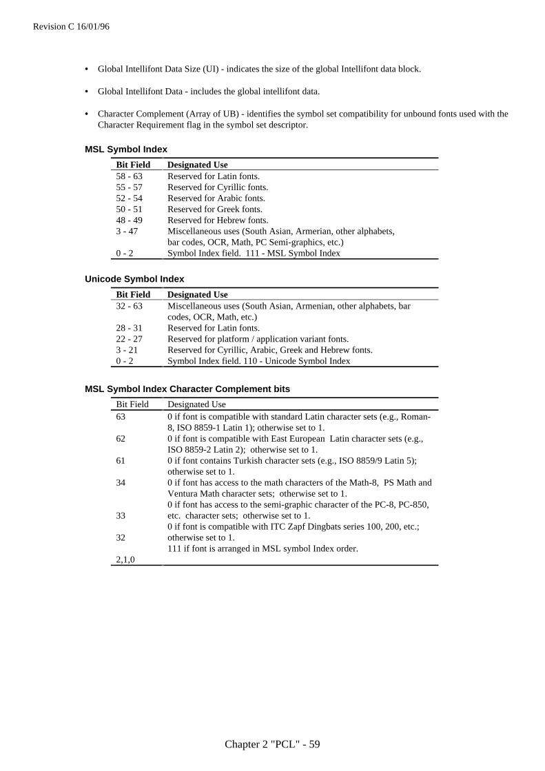
Revision C 16/01/96
Chapter 2 "PCL" - 59
• Global Intellifont Data Size (UI) - indicates the size of the global Intellifont data block.
• Global Intellifont Data - includes the global intellifont data.
• Character Complement (Array of UB) - identifies the symbol set compatibility for unbound fonts used with theCharacter Requirement flag in the symbol set descriptor.
MSL Symbol Index
Bit Field Designated Use58 - 6355 - 5752 - 5450 - 5148 - 493 - 47
0 - 2
Reserved for Latin fonts.Reserved for Cyrillic fonts.Reserved for Arabic fonts.Reserved for Greek fonts.Reserved for Hebrew fonts.Miscellaneous uses (South Asian, Armerian, other alphabets,bar codes, OCR, Math, PC Semi-graphics, etc.)Symbol Index field. 111 - MSL Symbol Index
Unicode Symbol Index
Bit Field Designated Use32 - 63
28 - 3122 - 273 - 210 - 2
Miscellaneous uses (South Asian, Armenian, other alphabets, barcodes, OCR, Math, etc.)Reserved for Latin fonts.Reserved for platform / application variant fonts.Reserved for Cyrillic, Arabic, Greek and Hebrew fonts.Symbol Index field. 110 - Unicode Symbol Index
MSL Symbol Index Character Complement bits
Bit Field Designated Use63
62
61
34
33
32
2,1,0
0 if font is compatible with standard Latin character sets (e.g., Roman-8, ISO 8859-1 Latin 1); otherwise set to 1.0 if font is compatible with East European Latin character sets (e.g.,ISO 8859-2 Latin 2); otherwise set to 1.0 if font contains Turkish character sets (e.g., ISO 8859/9 Latin 5);otherwise set to 1.0 if font has access to the math characters of the Math-8, PS Math andVentura Math character sets; otherwise set to 1.0 if font has access to the semi-graphic character of the PC-8, PC-850,etc. character sets; otherwise set to 1.0 if font is compatible with ITC Zapf Dingbats series 100, 200, etc.;otherwise set to 1.111 if font is arranged in MSL symbol Index order.

Revision C 16/01/96
Chapter 2 "PCL" - 60
Unicode Symbol Index Character Complement bits
Bit Field Designated Use3130
29
28
27
26
25
24
23
22
2,1,0
0 if font is compatible with 7-bit ASCII; otherwise set to 1.0 if font is compatible with ISO 8859/1 Latin 1 (West Europe)character sets; otherwise set to 1.0 if font is compatible with ISO 8859/2 Latin 2 (East Europe) charactersets; otherwise set to 1.0 if font is compatible with Latin 5 (Turkish) character sets (e.g., ISO8859/9 Latin 5,PC-Turkish); otherwise set to 1.0 if font is compatible with Desktop Publishing character sets (e.g.,Windows 3.1 Latin 1, DeskTop, MC Text); otherwise set to 1.0 if font is compatible with character sets requiring a widerselection of accents (e.g., MC Text, ISo 8859/1 Latin 1);otherwise set to 1.0 if font is compatible with traditional PCL character sets (e.g.,Roman-8, Legal, ISO 4 United Kingdom); otherwise set to 1.0 if font is compatible with the Macintosh character set (MSText); otherwise set to 1.0 if font is compatible with PostScript Standard Encoding (PS Text);otherwise set to 1.0 if font is compatible with Code Pages (e.g., PC-8, PC-850,PC-Turk, etc.); otherwise set to 1.110 if font is arranged in Unicode Symbol Index order.
• Checksum - This should be set to a value which, when added to the contents of the 64 bytes of this fontdescriptor data produces a total of 0.
• Descriptor size - segmented font data.
MSB15 8
LSB7 0
x First segment, segment identifierx + 2 First segment, Segment sizex + 4 First segment, Data segment
x + 4 + 1stseg. size
Second segment,segment identifier, Size, Data segment
| |# - 6 Null segment identifier# - 4 Null segment size# - 2 Reserved Checksum
This segment follows just after the font header for TrueType. Each segment is divided into segment identifier,segment size, and data segment parts.
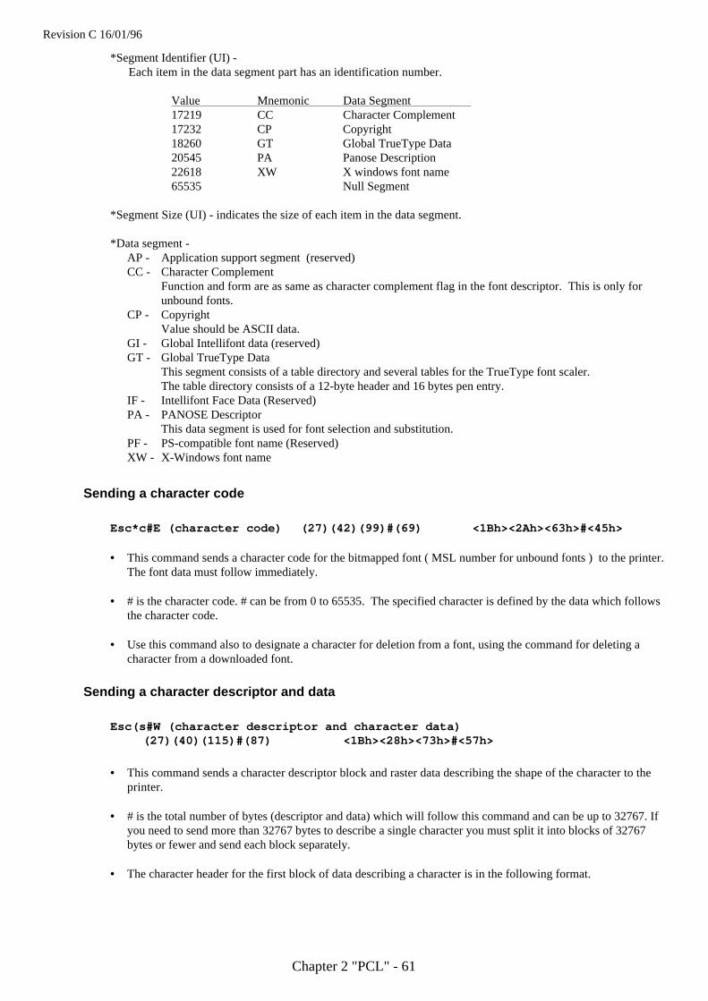
Revision C 16/01/96
Chapter 2 "PCL" - 61
*Segment Identifier (UI) -Each item in the data segment part has an identification number.
Value Mnemonic Data Segment 17219 CC Character Complement17232 CP Copyright18260 GT Global TrueType Data20545 PA Panose Description22618 XW X windows font name65535 Null Segment
*Segment Size (UI) - indicates the size of each item in the data segment.
*Data segment -AP - Application support segment (reserved)CC - Character Complement
Function and form are as same as character complement flag in the font descriptor. This is only forunbound fonts.
CP - CopyrightValue should be ASCII data.
GI - Global Intellifont data (reserved)GT - Global TrueType Data
This segment consists of a table directory and several tables for the TrueType font scaler.The table directory consists of a 12-byte header and 16 bytes pen entry.
IF - Intellifont Face Data (Reserved)PA - PANOSE Descriptor
This data segment is used for font selection and substitution.PF - PS-compatible font name (Reserved)XW - X-Windows font name
Sending a character code
Esc*c#E (character code) (27)(42)(99)#(69) <1Bh><2Ah><63h>#<45h>
• This command sends a character code for the bitmapped font ( MSL number for unbound fonts ) to the printer.The font data must follow immediately.
• # is the character code. # can be from 0 to 65535. The specified character is defined by the data which followsthe character code.
• Use this command also to designate a character for deletion from a font, using the command for deleting acharacter from a downloaded font.
Sending a character descriptor and data
Esc(s#W (character descriptor and character data) (27)(40)(115)#(87) <1Bh><28h><73h>#<57h>
• This command sends a character descriptor block and raster data describing the shape of the character to theprinter.
• # is the total number of bytes (descriptor and data) which will follow this command and can be up to 32767. Ifyou need to send more than 32767 bytes to describe a single character you must split it into blocks of 32767bytes or fewer and send each block separately.
• The character header for the first block of data describing a character is in the following format.
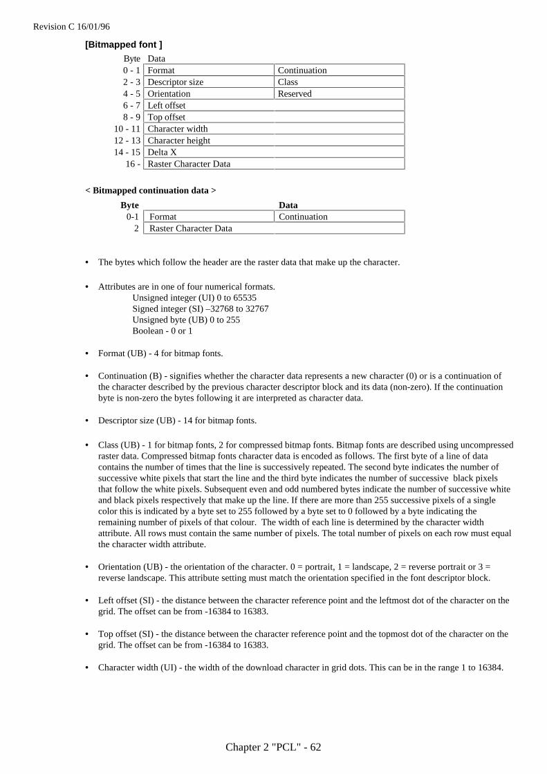
Revision C 16/01/96
Chapter 2 "PCL" - 62
[Bitmapped font ]
Byte Data0 - 1 Format Continuation2 - 3 Descriptor size Class4 - 5 Orientation Reserved6 - 7 Left offset8 - 9 Top offset
10 - 11 Character width12 - 13 Character height14 - 15 Delta X
16 - Raster Character Data
< Bitmapped continuation data >
Byte Data0-1 Format Continuation
2 Raster Character Data
• The bytes which follow the header are the raster data that make up the character.
• Attributes are in one of four numerical formats.Unsigned integer (UI) 0 to 65535Signed integer (SI) –32768 to 32767Unsigned byte (UB) 0 to 255Boolean - 0 or 1
• Format (UB) - 4 for bitmap fonts.
• Continuation (B) - signifies whether the character data represents a new character (0) or is a continuation ofthe character described by the previous character descriptor block and its data (non-zero). If the continuationbyte is non-zero the bytes following it are interpreted as character data.
• Descriptor size (UB) - 14 for bitmap fonts.
• Class (UB) - 1 for bitmap fonts, 2 for compressed bitmap fonts. Bitmap fonts are described using uncompressedraster data. Compressed bitmap fonts character data is encoded as follows. The first byte of a line of datacontains the number of times that the line is successively repeated. The second byte indicates the number ofsuccessive white pixels that start the line and the third byte indicates the number of successive black pixelsthat follow the white pixels. Subsequent even and odd numbered bytes indicate the number of successive whiteand black pixels respectively that make up the line. If there are more than 255 successive pixels of a singlecolor this is indicated by a byte set to 255 followed by a byte set to 0 followed by a byte indicating theremaining number of pixels of that colour. The width of each line is determined by the character widthattribute. All rows must contain the same number of pixels. The total number of pixels on each row must equalthe character width attribute.
• Orientation (UB) - the orientation of the character. 0 = portrait, 1 = landscape, 2 = reverse portrait or 3 =reverse landscape. This attribute setting must match the orientation specified in the font descriptor block.
• Left offset (SI) - the distance between the character reference point and the leftmost dot of the character on thegrid. The offset can be from -16384 to 16383.
• Top offset (SI) - the distance between the character reference point and the topmost dot of the character on thegrid. The offset can be from -16384 to 16383.
• Character width (UI) - the width of the download character in grid dots. This can be in the range 1 to 16384.
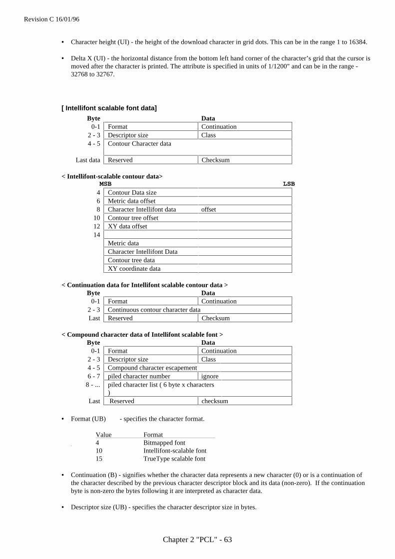
Revision C 16/01/96
Chapter 2 "PCL" - 63
• Character height (UI) - the height of the download character in grid dots. This can be in the range 1 to 16384.
• Delta X (UI) - the horizontal distance from the bottom left hand corner of the character’s grid that the cursor ismoved after the character is printed. The attribute is specified in units of 1/1200" and can be in the range -32768 to 32767.
[ Intellifont scalable font data]
Byte Data0-1 Format Continuation
2 - 3 Descriptor size Class4 - 5 Contour Character data
Last data Reserved Checksum
< Intellifont-scalable contour data>MSB LSB
4 Contour Data size6 Metric data offset8 Character Intellifont data offset
10 Contour tree offset12 XY data offset14
Metric dataCharacter Intellifont DataContour tree dataXY coordinate data
< Continuation data for Intellifont scalable contour data >Byte Data
0-1 Format Continuation2 - 3 Continuous contour character dataLast Reserved Checksum
< Compound character data of Intellifont scalable font >Byte Data
0-1 Format Continuation2 - 3 Descriptor size Class4 - 5 Compound character escapement6 - 7 piled character number ignore
8 - ... piled character list ( 6 byte x characters)
Last Reserved checksum
• Format (UB) - specifies the character format.
Value Format 4 Bitmapped font
10 Intellifont-scalable font15 TrueType scalable font
• Continuation (B) - signifies whether the character data represents a new character (0) or is a continuation ofthe character described by the previous character descriptor block and its data (non-zero). If the continuationbyte is non-zero the bytes following it are interpreted as character data.
• Descriptor size (UB) - specifies the character descriptor size in bytes.
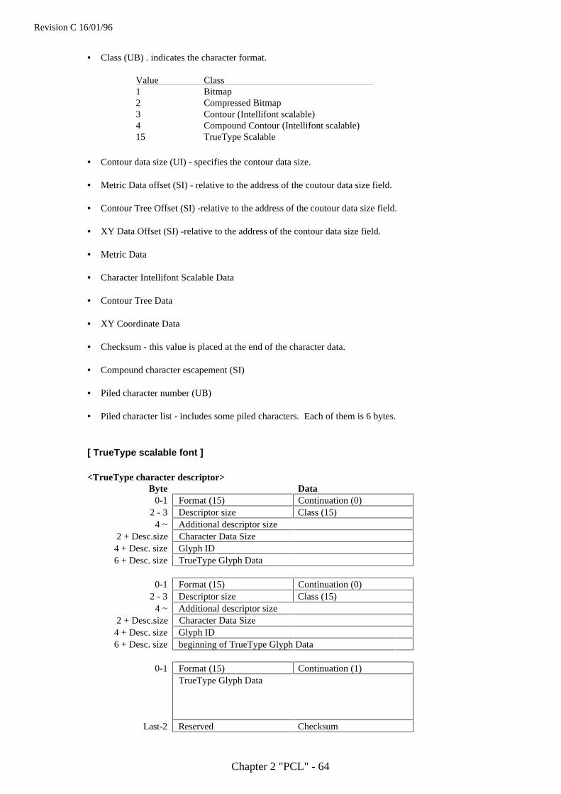
Revision C 16/01/96
Chapter 2 "PCL" - 64
• Class (UB) . indicates the character format.
Value Class 1 Bitmap2 Compressed Bitmap3 Contour (Intellifont scalable)4 Compound Contour (Intellifont scalable)15 TrueType Scalable
• Contour data size (UI) - specifies the contour data size.
• Metric Data offset (SI) - relative to the address of the coutour data size field.
• Contour Tree Offset (SI) -relative to the address of the coutour data size field.
• XY Data Offset (SI) -relative to the address of the contour data size field.
• Metric Data
• Character Intellifont Scalable Data
• Contour Tree Data
• XY Coordinate Data
• Checksum - this value is placed at the end of the character data.
• Compound character escapement (SI)
• Piled character number (UB)
• Piled character list - includes some piled characters. Each of them is 6 bytes.
[ TrueType scalable font ]
<TrueType character descriptor>Byte Data
0-1 Format (15) Continuation (0)2 - 3 Descriptor size Class (15)4 ~ Additional descriptor size
2 + Desc.size Character Data Size4 + Desc. size Glyph ID6 + Desc. size TrueType Glyph Data
0-1 Format (15) Continuation (0)2 - 3 Descriptor size Class (15)4 ~ Additional descriptor size
2 + Desc.size Character Data Size4 + Desc. size Glyph ID6 + Desc. size beginning of TrueType Glyph Data
0-1 Format (15) Continuation (1)TrueType Glyph Data
Last-2 Reserved Checksum
Revision C 16/01/96
Chapter 2 "PCL" - 65
• The character data follows these header bytes. Characters are represented as raster data and the data bytes areused to build up an image of the character from left to right and from top to bottom, according to the characterwidth and height settings.
• Format (UB) - 15 specifies TrueType font.
• Continuation (B) - specifies whether the character data represents a new character (0) or is a continuation ofthe character described by the previous character descriptor block (non-zero). If the continuation byte is non-zero the bytes following it are interpreted as character data.
• Descriptor size (UB) - specifies the character descriptor size in bytes.
• Class (UB) - indicates the character format.
Value Class 1 Bitmap2 Compressed Bitmap3 Contour (Intellifont scalable)4 Compound Contour (Intellifont scalable)15 TrueType scalable
• Character data size (UI) - should be the same value as (the character data size + Glyph ID + TrueType Glyphdata) size.
• Glyph ID (UI) - specifies the ID number for glyph data, which is used by TrueType font scaler.
• TrueType Glyph data - includes the data segment which is associated with the given character as found in theglyph table of the original TrueType font file.
• Checksum (UB) - should be a value which, when added to "Character data + Glyph ID + TrueType Glyphdata" size, produces a zero result.
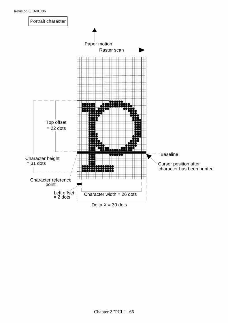
Revision C 16/01/96
Chapter 2 "PCL" - 66
Paper motionRaster scan
Top offset= 22 dots
Character height= 31 dots
Baseline
Cursor position after character has been printed
Character width = 26 dots
Delta X = 30 dots
Left offset = 2 dots
Character referencepoint
Portrait character
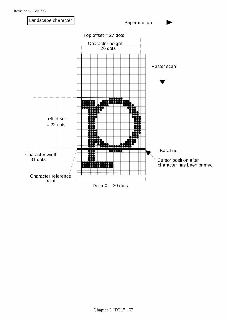
Revision C 16/01/96
Chapter 2 "PCL" - 67
Paper motion
Raster scan
Left offset= 22 dots
Character width= 31 dots
Baseline
Cursor position after character has been printed
Delta X = 30 dots
Character referencepoint
Top offset = 27 dots
Character height= 26 dots
Landscape character

Revision C 16/01/96
Chapter 2 "PCL" - 68
Using graphics
This HL Series printer affords the user considerable flexibility in the creation of graphic images. Vector, raster andrectangle graphics are available, all of which allow a range of shading and filling options. The HP-GL/2 graphicscommands that are supported are described in the HP-GL/2 section of this manual.
Source, pattern and destinationWe refer to a printing model in which a source image (the image to be drawn) is applied to a destination image(simply the graphics or text that already exist on the page). The source image consists of white space and non-white areas. The non-white areas are covered by a pattern of some description. The pattern may simply be solidblack or it may itself consist of white and non-white areas, for example the pattern may consist of vertical spacedlines. You can specify the way in which the white and dark areas of the entire source image and the white anddark areas of the pattern interact with the destination image to produce the finished effect.
For example
Pattern
Source image
Destination image
Possible results
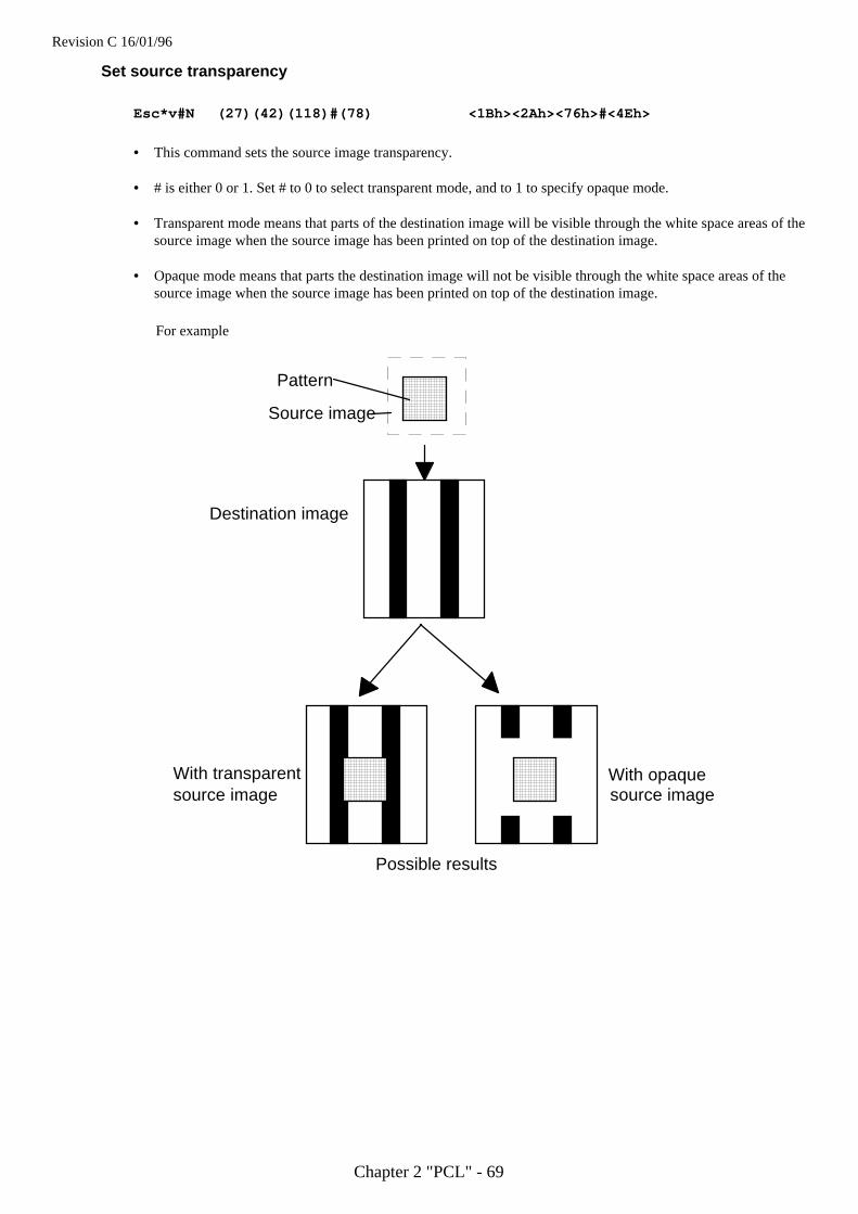
Revision C 16/01/96
Chapter 2 "PCL" - 69
Set source transparency
Esc*v#N (27)(42)(118)#(78) <1Bh><2Ah><76h>#<4Eh>
• This command sets the source image transparency.
• # is either 0 or 1. Set # to 0 to select transparent mode, and to 1 to specify opaque mode.
• Transparent mode means that parts of the destination image will be visible through the white space areas of thesource image when the source image has been printed on top of the destination image.
• Opaque mode means that parts the destination image will not be visible through the white space areas of thesource image when the source image has been printed on top of the destination image.
For example
Pattern
Source image
Destination image
Possible results
With transparentsource image
With opaquesource image
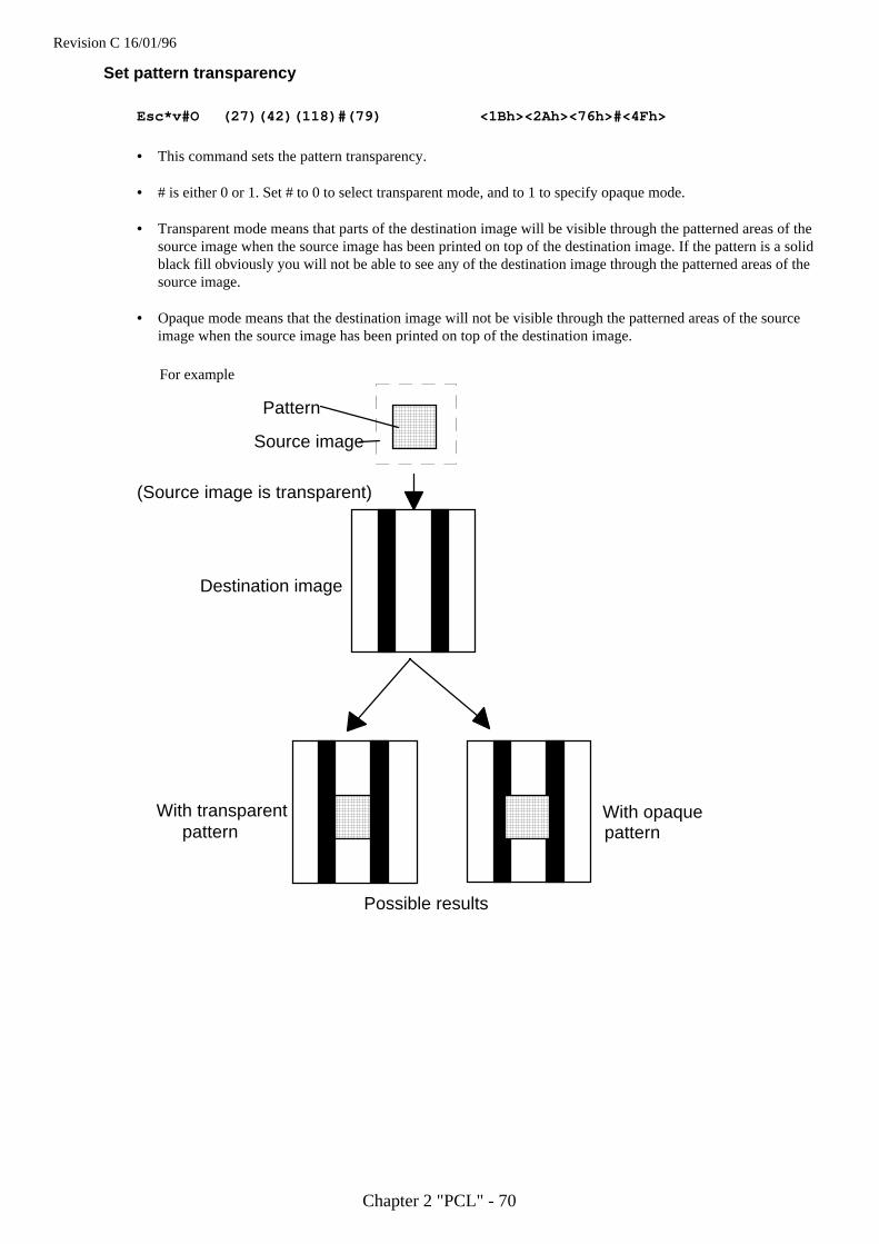
Revision C 16/01/96
Chapter 2 "PCL" - 70
Set pattern transparency
Esc*v#O (27)(42)(118)#(79) <1Bh><2Ah><76h>#<4Fh>
• This command sets the pattern transparency.
• # is either 0 or 1. Set # to 0 to select transparent mode, and to 1 to specify opaque mode.
• Transparent mode means that parts of the destination image will be visible through the patterned areas of thesource image when the source image has been printed on top of the destination image. If the pattern is a solidblack fill obviously you will not be able to see any of the destination image through the patterned areas of thesource image.
• Opaque mode means that the destination image will not be visible through the patterned areas of the sourceimage when the source image has been printed on top of the destination image.
For example
Pattern
Source image
Destination image
Possible results
With transparentpattern
With opaquepattern
(Source image is transparent)
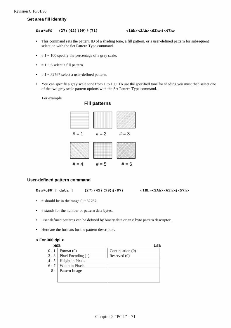
Revision C 16/01/96
Chapter 2 "PCL" - 71
Set area fill identity
Esc*c#G (27)(42)(99)#(71) <1Bh><2Ah><63h>#<47h>
• This command sets the pattern ID of a shading tone, a fill pattern, or a user-defined pattern for subsequentselection with the Set Pattern Type command.
• # 1 ~ 100 specify the percentage of a gray scale.
• # 1 ~ 6 select a fill pattern.
• # 1 ~ 32767 select a user-defined pattern.
• You can specify a gray scale tone from 1 to 100. To use the specified tone for shading you must then select oneof the two gray scale pattern options with the Set Pattern Type command.
For example
# = 1 # = 2 # = 3
# = 4 # = 5 # = 6
Fill patterns
User-defined pattern command
Esc*c#W [ data ] (27)(42)(99)#(87) <1Bh><2Ah><63h>#<57h>
• # should be in the range 0 ~ 32767.
• # stands for the number of pattern data bytes.
• User defined patterns can be defined by binary data or an 8 byte pattern descriptor.
• Here are the formats for the pattern descriptor.
< For 300 dpi > MSB LSB
0 - 1 Format (0) Continuation (0)2 - 3 Pixel Encoding (1) Reserved (0)4 - 5 Height in Pixels6 - 7 Width in Pixels
8 - Pattern Image
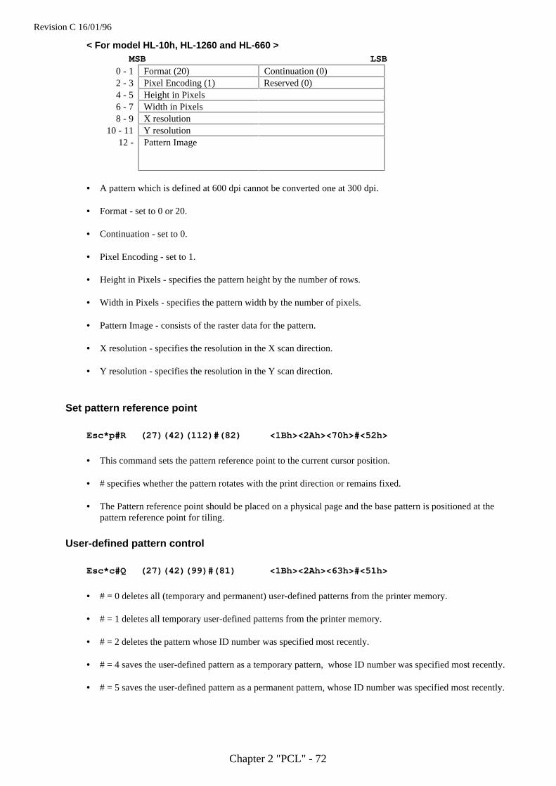
Revision C 16/01/96
Chapter 2 "PCL" - 72
< For model HL-10h, HL-1260 and HL-660 > MSB LSB
0 - 1 Format (20) Continuation (0)2 - 3 Pixel Encoding (1) Reserved (0)4 - 5 Height in Pixels6 - 7 Width in Pixels8 - 9 X resolution
10 - 11 Y resolution12 - Pattern Image
• A pattern which is defined at 600 dpi cannot be converted one at 300 dpi.
• Format - set to 0 or 20.
• Continuation - set to 0.
• Pixel Encoding - set to 1.
• Height in Pixels - specifies the pattern height by the number of rows.
• Width in Pixels - specifies the pattern width by the number of pixels.
• Pattern Image - consists of the raster data for the pattern.
• X resolution - specifies the resolution in the X scan direction.
• Y resolution - specifies the resolution in the Y scan direction.
Set pattern reference point
Esc*p#R (27)(42)(112)#(82) <1Bh><2Ah><70h>#<52h>
• This command sets the pattern reference point to the current cursor position.
• # specifies whether the pattern rotates with the print direction or remains fixed.
• The Pattern reference point should be placed on a physical page and the base pattern is positioned at thepattern reference point for tiling.
User-defined pattern control
Esc*c#Q (27)(42)(99)#(81) <1Bh><2Ah><63h>#<51h>
• # = 0 deletes all (temporary and permanent) user-defined patterns from the printer memory.
• # = 1 deletes all temporary user-defined patterns from the printer memory.
• # = 2 deletes the pattern whose ID number was specified most recently.
• # = 4 saves the user-defined pattern as a temporary pattern, whose ID number was specified most recently.
• # = 5 saves the user-defined pattern as a permanent pattern, whose ID number was specified most recently.
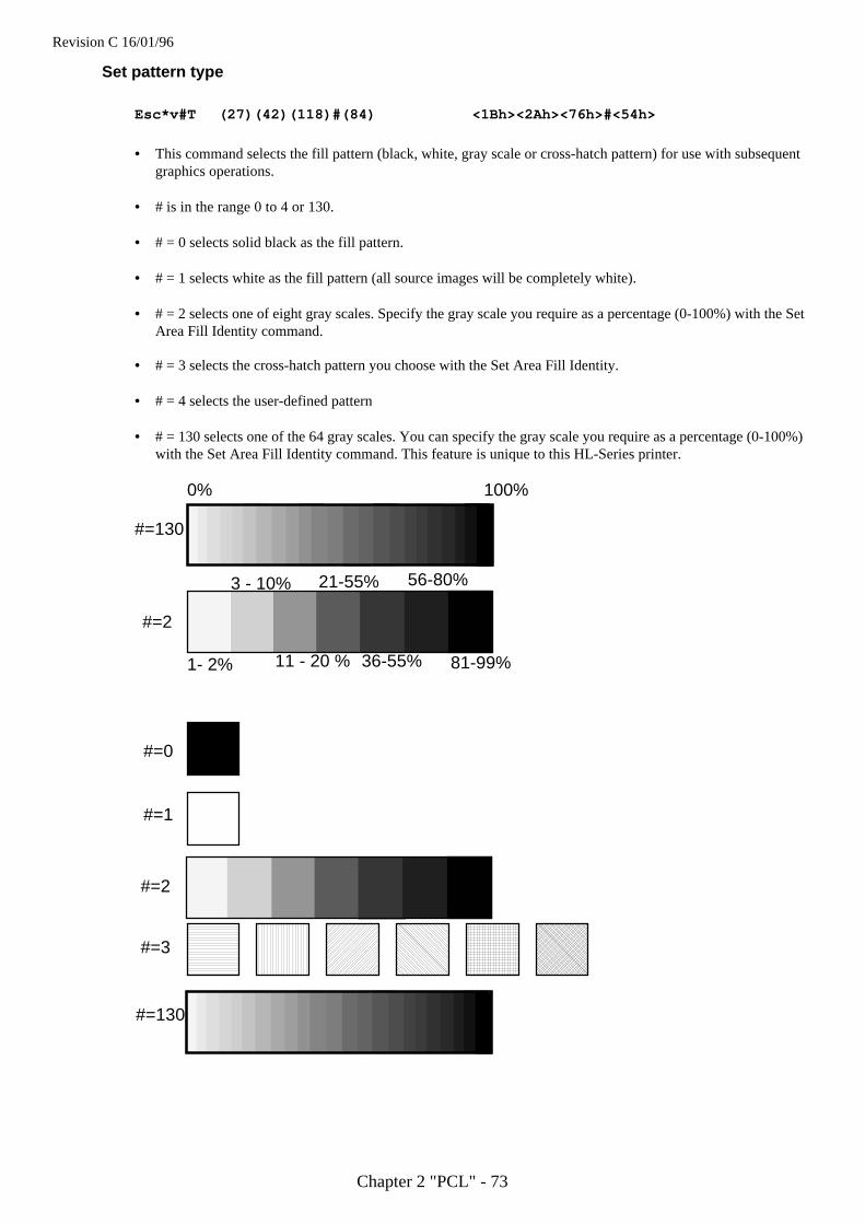
Revision C 16/01/96
Chapter 2 "PCL" - 73
Set pattern type
Esc*v#T (27)(42)(118)#(84) <1Bh><2Ah><76h>#<54h>
• This command selects the fill pattern (black, white, gray scale or cross-hatch pattern) for use with subsequentgraphics operations.
• # is in the range 0 to 4 or 130.
• # = 0 selects solid black as the fill pattern.
• # = 1 selects white as the fill pattern (all source images will be completely white).
• # = 2 selects one of eight gray scales. Specify the gray scale you require as a percentage (0-100%) with the SetArea Fill Identity command.
• # = 3 selects the cross-hatch pattern you choose with the Set Area Fill Identity.
• # = 4 selects the user-defined pattern
• # = 130 selects one of the 64 gray scales. You can specify the gray scale you require as a percentage (0-100%)with the Set Area Fill Identity command. This feature is unique to this HL-Series printer.
0% 100%
1- 2%
3 - 10%
11 - 20 %
21-55%
36-55%
56-80%
81-99%
#=0
#=1
#=2
#=3
#=130
#=2
#=130
Revision C 16/01/96
Chapter 2 "PCL" - 74
Pattern example
10 WIDTH "LPT1:", 25520 ESC$ = CHR$(27)30 REM --- RESET PRINTER ---40 LPRINT ESC$; "E";50 REM --- SET SOURCE=TRANSPARENT ---60 REM --- SET PATTERN=OPAQUE ---70 LPRINT ESC$; "*v0n1O";80 REM --- BACKGROUND ---90 LPRINT ESC$; "*c80G"; ESC$; "*v2T";100 LPRINT ESC$; "*p100x100Y"; ESC$; "*c1000a300b2P";110 REM --- PATTERN ---120 LPRINT ESC$; "*p150x300Y";130 LPRINT ESC$; "(s1p48v0s0b4101T";140 LPRINT ESC$; "*c1G"; ESC$; "*v3T"; : LPRINT "P";150 LPRINT ESC$; "*c2G"; ESC$; "*v3T"; : LPRINT "A";160 LPRINT ESC$; "*c6G"; ESC$; "*v3T"; : LPRINT "T";170 LPRINT ESC$; "*c4G"; ESC$; "*v3T"; : LPRINT "T";180 LPRINT ESC$; "*c5G"; ESC$; "*v3T"; : LPRINT "E";190 LPRINT ESC$; "*c3G"; ESC$; "*v3T"; : LPRINT "R";200 LPRINT ESC$; "*c1G"; ESC$; "*v3T"; : LPRINT "N";210 REM --- PAPER EJECT ---220 LPRINT CHR$(12);230 END
< Sample file 6 >
Plotting rectanglesDrawing rectangles is a basic case of printing graphics: the source image consists solely of the rectangle itself.Thus only the pattern transparency has any bearing on the final effect - the source transparency is irrelevant.
Cursor positionPosition the cursor using the commands described in the chapter entitled “The Page”. You can use units,decipoints or rows and columns as coordinate units. Remember that the y-coordinate value goes up as the cursormoves down the logical page.
Set rectangle width
Esc*c#A (27)(42)(99)#(65) <1Bh><2Ah><63h>#<41h>
• This command sets the width of the rectangle to be printed in dots.
• # is a number of dots.
Esc*c#H (27)(42)(99)#(72) <1Bh><2Ah><63h>#<48h>
• This command sets the width of the rectangle to be printed in decipoints.
• # is a number of decipoints.
Revision C 16/01/96
Chapter 2 "PCL" - 75
Set rectangle height
Esc*c#B (27)(42)(99)#(66) <1Bh><2Ah><63h>#<42h>
• This command sets the height of the rectangle to be printed in dots.
• # is a number of dots.
Esc*c#V (27)(42)(99)#(86) <1Bh><2Ah><63h>#<56h>
• This command sets the height of the rectangle to be printed in decipoints.
• # is a number of decipoints.
Draw filled rectangle
Esc*c#P (27)(42)(99)#(80) <1Bh><2Ah><63h>#<50h>
• This command fills a rectangular area with the specified shading option.
• # is 0 to 5 or 130.
• # = 0 uses solid black as the fill pattern.
• # = 1 uses white as the fill pattern.
• # = 2 selects the gray scale you chose with the Set Area Fill Identity command as the fill pattern.
• # = 3 selects the cross-hatch pattern you chose with the Set Area Fill Identity.
• # = 4 selects the user defined pattern, which is a specified ID number selected by the set Area Fill Identity.
• # = 5 uses the pattern specified by the combination of the most recent Set Area Fill Identity command and themost recent Set Pattern Type command.
• # = 130 selects one of the sixty-four gray scales. You can specify the gray scale you require as a percentage (0-100%) with the Set Area Fill Identity command. This feature is unique to this HL Series printer.
• See following two pages for programming examples using gray scales and patterns
# Fill0 Solid black1 White2 Gray scale (1 - 8)3 Cross hatch pattern4 User-defined pattern5 Current pattern
130 Gray scale ( 1 - 64)
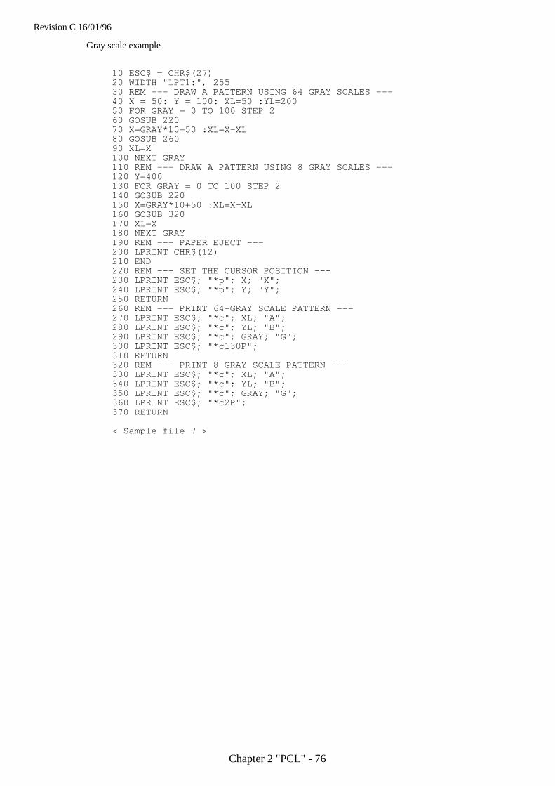
Revision C 16/01/96
Chapter 2 "PCL" - 76
Gray scale example
10 ESC$ = CHR$(27)20 WIDTH "LPT1:", 25530 REM --- DRAW A PATTERN USING 64 GRAY SCALES ---40 X = 50: Y = 100: XL=50 :YL=20050 FOR GRAY = 0 TO 100 STEP 260 GOSUB 22070 X=GRAY*10+50 :XL=X-XL80 GOSUB 26090 XL=X100 NEXT GRAY110 REM --- DRAW A PATTERN USING 8 GRAY SCALES ---120 Y=400130 FOR GRAY = 0 TO 100 STEP 2140 GOSUB 220150 X=GRAY*10+50 :XL=X-XL160 GOSUB 320170 XL=X180 NEXT GRAY190 REM --- PAPER EJECT ---200 LPRINT CHR$(12)210 END220 REM --- SET THE CURSOR POSITION ---230 LPRINT ESC$; "*p"; X; "X";240 LPRINT ESC$; "*p"; Y; "Y";250 RETURN260 REM --- PRINT 64-GRAY SCALE PATTERN ---270 LPRINT ESC$; "*c"; XL; "A";280 LPRINT ESC$; "*c"; YL; "B";290 LPRINT ESC$; "*c"; GRAY; "G";300 LPRINT ESC$; "*c130P";310 RETURN320 REM --- PRINT 8-GRAY SCALE PATTERN ---330 LPRINT ESC$; "*c"; XL; "A";340 LPRINT ESC$; "*c"; YL; "B";350 LPRINT ESC$; "*c"; GRAY; "G";360 LPRINT ESC$; "*c2P";370 RETURN
< Sample file 7 >

Revision C 16/01/96
Chapter 2 "PCL" - 77
Raster graphics
Positioning the cursorPosition the cursor using the commands described in the chapter entitled “The Page”, using dots, decipoints orrows and columns as coordinate units.
Set raster resolution
Esc*t#R (27)(42)(116)#(82) <1Bh><2Ah><74h>#<52h>
• This command sets the raster image resolution in dots per inch.
• # is 75, 100, 150, 200, 300 or 600.
• The lower the resolution you specify, the less printer memory your raster image will occupy.
• Use this command before you issue a Begin Raster Graphics command, otherwise the resolution that youspecify will not take effect until the next time you re-enter raster graphics mode.
Set high resolution control
EscCRRO (27)(13)(82)(79) <1Bh><0Dh><52h><4Fh>• This command sets high resolution control off.
EscCRRL (27)(13)(82)(76) <1Bh><0Dh><52h><4Ch>• This command sets high resolution control light level.
EscCRRM (27)(13)(82)(77) <1Bh><0Dh><52h><4Dh>• This command sets high resolution control Medium level.
EscCRRD (27)(13)(82)(68) <1Bh><0Dh><52h><44h>• This command sets high resolution control dark level.
Set raster image orientation
Esc*r#F (27)(42)(114)#(70) <1Bh><2Ah><72h>#<46h>
• This command specifies the orientation of the raster image.
• # is 0 or 3.
• # = 0 determines that the image will be printed from left to right and from top to bottom within the currentlogical page.
• # = 3 determines that the image will be printed from left to right and from top to bottom within the currentphysical page irrespective of logical page orientation.
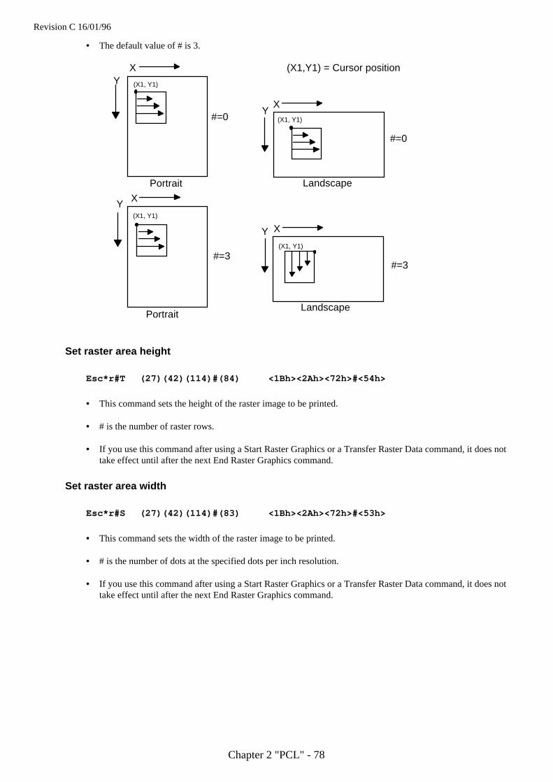
Revision C 16/01/96
Chapter 2 "PCL" - 78
• The default value of # is 3.
X
Y
Y
Y
Y
X
X
X
(X1, Y1)
(X1, Y1)
(X1, Y1)
(X1, Y1)
Portrait Landscape
PortraitLandscape
#=0
#=0
#=3#=3
(X1,Y1) = Cursor position
Set raster area height
Esc*r#T (27)(42)(114)#(84) <1Bh><2Ah><72h>#<54h>
• This command sets the height of the raster image to be printed.
• # is the number of raster rows.
• If you use this command after using a Start Raster Graphics or a Transfer Raster Data command, it does nottake effect until after the next End Raster Graphics command.
Set raster area width
Esc*r#S (27)(42)(114)#(83) <1Bh><2Ah><72h>#<53h>
• This command sets the width of the raster image to be printed.
• # is the number of dots at the specified dots per inch resolution.
• If you use this command after using a Start Raster Graphics or a Transfer Raster Data command, it does nottake effect until after the next End Raster Graphics command.
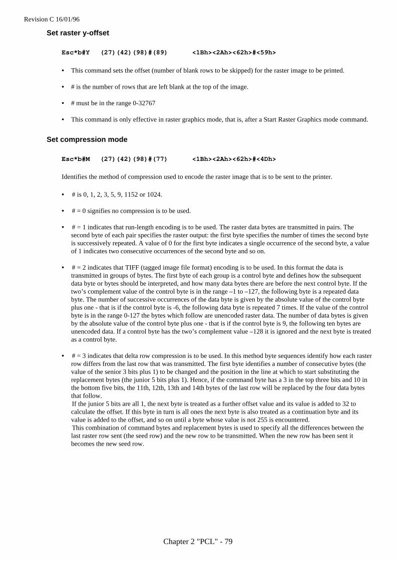
Revision C 16/01/96
Chapter 2 "PCL" - 79
Set raster y-offset
Esc*b#Y (27)(42)(98)#(89) <1Bh><2Ah><62h>#<59h>
• This command sets the offset (number of blank rows to be skipped) for the raster image to be printed.
• # is the number of rows that are left blank at the top of the image.
• # must be in the range 0-32767
• This command is only effective in raster graphics mode, that is, after a Start Raster Graphics mode command.
Set compression mode
Esc*b#M (27)(42)(98)#(77) <1Bh><2Ah><62h>#<4Dh>
Identifies the method of compression used to encode the raster image that is to be sent to the printer.
• # is 0, 1, 2, 3, 5, 9, 1152 or 1024.
• # = 0 signifies no compression is to be used.
• # = 1 indicates that run-length encoding is to be used. The raster data bytes are transmitted in pairs. Thesecond byte of each pair specifies the raster output: the first byte specifies the number of times the second byteis successively repeated. A value of 0 for the first byte indicates a single occurrence of the second byte, a valueof 1 indicates two consecutive occurrences of the second byte and so on.
• # = 2 indicates that TIFF (tagged image file format) encoding is to be used. In this format the data istransmitted in groups of bytes. The first byte of each group is a control byte and defines how the subsequentdata byte or bytes should be interpreted, and how many data bytes there are before the next control byte. If thetwo’s complement value of the control byte is in the range –1 to –127, the following byte is a repeated databyte. The number of successive occurrences of the data byte is given by the absolute value of the control byteplus one - that is if the control byte is -6, the following data byte is repeated 7 times. If the value of the controlbyte is in the range 0-127 the bytes which follow are unencoded raster data. The number of data bytes is givenby the absolute value of the control byte plus one - that is if the control byte is 9, the following ten bytes areunencoded data. If a control byte has the two’s complement value –128 it is ignored and the next byte is treatedas a control byte.
• # = 3 indicates that delta row compression is to be used. In this method byte sequences identify how each rasterrow differs from the last row that was transmitted. The first byte identifies a number of consecutive bytes (thevalue of the senior 3 bits plus 1) to be changed and the position in the line at which to start substituting thereplacement bytes (the junior 5 bits plus 1). Hence, if the command byte has a 3 in the top three bits and 10 inthe bottom five bits, the 11th, 12th, 13th and 14th bytes of the last row will be replaced by the four data bytesthat follow.If the junior 5 bits are all 1, the next byte is treated as a further offset value and its value is added to 32 tocalculate the offset. If this byte in turn is all ones the next byte is also treated as a continuation byte and itsvalue is added to the offset, and so on until a byte whose value is not 255 is encountered.This combination of command bytes and replacement bytes is used to specify all the differences between thelast raster row sent (the seed row) and the new row to be transmitted. When the new row has been sent itbecomes the new seed row.
Revision C 16/01/96
Chapter 2 "PCL" - 80
• # = 5 indicates that adaptive compression is to be used.
This compression compresses multiple rows (block) into one transfer graphics command.Most of other compression method compresses only one row to one transfer graphics command.One transfer graphic command (ESC *b##W) can contain only up to 32,767 bytes.As mode 5 compression compresses multiple rows, the amount of transferred data may become large.If compressed data exceeds this limit, please reduce the number of rows in one block.We can use mode 0 to mode 3 compression to compress each row. We can even compress empty (white) rowsand duplicate rows in this compression.
Command byteMode 5 compressed data consists of multiple elements. Each element contains 3 header bytes at the biginning.The first byte of the header bytes is a command byte.
First byte Second, third byte
0 Unencoded1 Run-length Encoding Number of a block data2 TIFF3 Delta Row compression
4 Empty Row Number of empty row or repetition5 Duplicate Row
Command byte
0 - This element is an uncompressed row. Next two bytes contain byte count of uncompressed data.Uncompressed data follows the header.
1 - This element identifies compressed row. Compression method is mode 1. Next two bytes (upperbyte first) contain byte count of compressed data. Compressed data follows the header.
2 - This element identifies a compressed row. Compression method is mode 2. Next two bytes(upper byte first) contain byte count of compressed data. Compressed data follows the header
3 - This element identifies a compressed row. Compression method is mode 3. Next two bytes(upper byte first) contain byte count of compressed data. Compressed data follows the header
4 - This element identifies multiple empty rows. Next two bytes (upper byte first) contain emptyrow count.
5 - This element identifies duplicate rows. Next two bytes (upper byte first) contain duplicate rowcount.
• # = 9 Mode 9 compression
Like mode 3 compression, this compression (mode 9) data contains only the difference of the current row fromthe preceding row.Replacement data often consists of a repetition of a particular byte in mode 3 compression.Mode 9 compression is effective in such cases.Simple mode 9 compression data consists of a command byte and the replacement data.A Command byte consists of 3 parts. They are the control bit, the offset count and the replacement count.The Control bit is the most significant bit (bit 7) of a control byte.
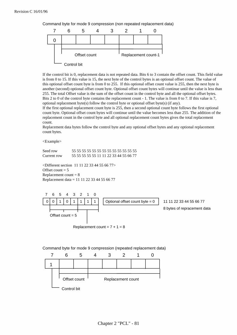
Revision C 16/01/96
Chapter 2 "PCL" - 81
7 6 5 4 3 2 1 0
Offset count Replacement count-1
Control bit
0
Command byte for mode 9 compression (non repeated replacement data)
If the control bit is 0, replacement data is not repeated data. Bits 6 to 3 contain the offset count. This field valueis from 0 to 15. If this value is 15, the next byte of the control bytes is an optional offset count. The value ofthis optional offset count byte is from 0 to 255. If this optional offset count value is 255, then the next byte isanother (second) optional offset count byte. Optional offset count bytes will continue until the value is less than255. The total Offset value is the sum of the offset count in the control byte and all the optional offset bytes.Bits 2 to 0 of the control byte contains the replacement count - 1. The value is from 0 to 7. If this value is 7,optional replacement byte(s) follow the control byte or optional offset byte(s) (if any).If the first optional replacement count byte is 255, then a second optional count byte follows the first optionalcount byte. Optional offset count bytes will continue until the value becomes less than 255. The addition of thereplacement count in the control byte and all optional replacement count bytes gives the total replacementcount.Replacement data bytes follow the control byte and any optional offset bytes and any optional replacementcount bytes.
<Example>
Seed row 55 55 55 55 55 55 55 55 55 55 55 55 55Current row 55 55 55 55 55 11 11 22 33 44 55 66 77
<Different section 11 11 22 33 44 55 66 77>Offset count = 5Replacement count = 8Replacement data = 11 11 22 33 44 55 66 77
0 0 1 0 1 1 1 1
7 6 5 4 3 2 1 0
Replacement count = 7 + 1 = 8
Offset count = 5
Optional offset count byte = 0
8 bytes of repracement data
11 11 22 33 44 55 66 77
7 6 5 4 3 2 1 0
Offset count Replacement count
Control bit
1
Command byte for mode 9 compression (repeated replacement data)
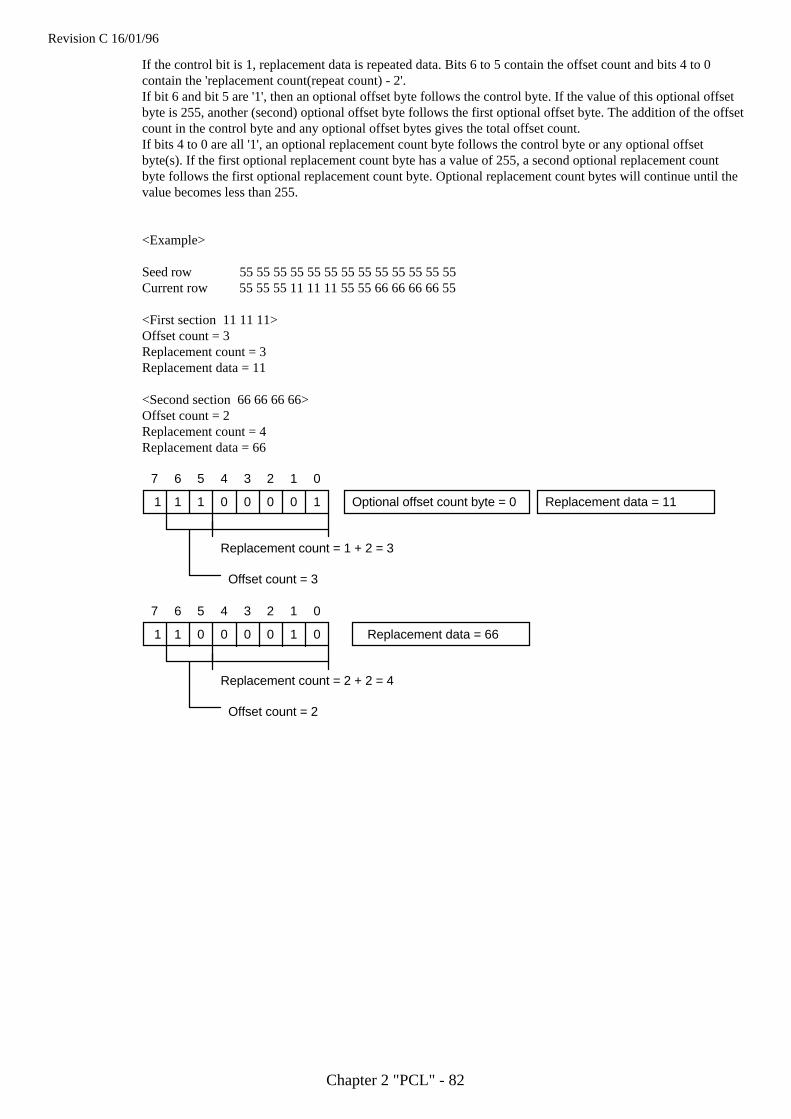
Revision C 16/01/96
Chapter 2 "PCL" - 82
If the control bit is 1, replacement data is repeated data. Bits 6 to 5 contain the offset count and bits 4 to 0contain the 'replacement count(repeat count) - 2'.If bit 6 and bit 5 are '1', then an optional offset byte follows the control byte. If the value of this optional offsetbyte is 255, another (second) optional offset byte follows the first optional offset byte. The addition of the offsetcount in the control byte and any optional offset bytes gives the total offset count.If bits 4 to 0 are all '1', an optional replacement count byte follows the control byte or any optional offsetbyte(s). If the first optional replacement count byte has a value of 255, a second optional replacement countbyte follows the first optional replacement count byte. Optional replacement count bytes will continue until thevalue becomes less than 255.
<Example>
Seed row 55 55 55 55 55 55 55 55 55 55 55 55 55Current row 55 55 55 11 11 11 55 55 66 66 66 66 55
<First section 11 11 11>Offset count = 3Replacement count = 3Replacement data = 11
<Second section 66 66 66 66>Offset count = 2Replacement count = 4Replacement data = 66
1 1 1 0 0 0 0 1
7 6 5 4 3 2 1 0
Replacement count = 1 + 2 = 3
Offset count = 3
Optional offset count byte = 0 Replacement data = 11
1 1 0 0 0 1 0
7 6 5 4 3 2 1 0
Replacement count = 2 + 2 = 4
Offset count = 2
Replacement data = 660
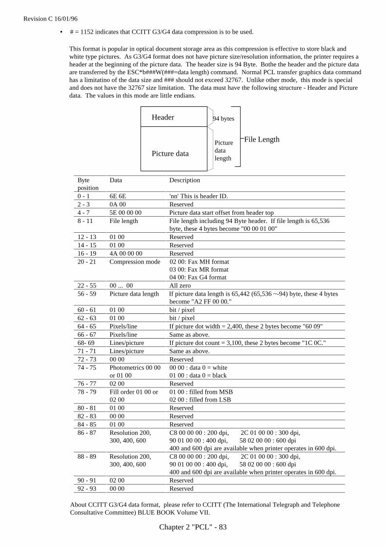
Revision C 16/01/96
Chapter 2 "PCL" - 83
• # = 1152 indicates that CCITT G3/G4 data compression is to be used.
This format is popular in optical document storage area as this compression is effective to store black andwhite type pictures. As G3/G4 format does not have picture size/resolution information, the printer requires aheader at the beginning of the picture data. The header size is 94 Byte. Bothe the header and the picture dataare transferred by the ESC*b###W(###=data length) command. Normal PCL transfer graphics data commandhas a limitatino of the data size and ### should not exceed 32767. Unlike other mode, this mode is specialand does not have the 32767 size limitation. The data must have the following structure - Header and Picturedata. The values in this mode are little endians.
Byteposition
Data Description
0 - 1 6E 6E 'nn' This is header ID.2 - 3 0A 00 Reserved4 - 7 5E 00 00 00 Picture data start offset from header top8 - 11 File length File length including 94 Byte header. If file length is 65,536
byte, these 4 bytes become "00 00 01 00"12 - 13 01 00 Reserved14 - 15 01 00 Reserved16 - 19 4A 00 00 00 Reserved20 - 21 Compression mode 02 00: Fax MH format
03 00: Fax MR format04 00: Fax G4 format
22 - 55 00 ... 00 All zero56 - 59 Picture data length If picture data length is 65,442 (65,536 ~-94) byte, these 4 bytes
become "A2 FF 00 00."60 - 61 01 00 bit / pixel62 - 63 01 00 bit / pixel64 - 65 Pixels/line If picture dot width = 2,400, these 2 bytes become "60 09"66 - 67 Pixels/line Same as above.68- 69 Lines/picture If picture dot count = 3,100, these 2 bytes become "1C 0C."71 - 71 Lines/picture Same as above.72 - 73 00 00 Reserved74 - 75 Photometrics 00 00
or 01 0000 00 : data 0 = white01 00 : data 0 = black
76 - 77 02 00 Reserved78 - 79 Fill order 01 00 or
02 0001 00 : filled from MSB02 00 : filled from LSB
80 - 81 01 00 Reserved82 - 83 00 00 Reserved84 - 85 01 00 Reserved86 - 87 Resolution 200,
300, 400, 600C8 00 00 00 : 200 dpi, 2C 01 00 00 : 300 dpi,90 01 00 00 : 400 dpi, 58 02 00 00 : 600 dpi400 and 600 dpi are available when printer operates in 600 dpi.
88 - 89 Resolution 200,300, 400, 600
C8 00 00 00 : 200 dpi, 2C 01 00 00 : 300 dpi,90 01 00 00 : 400 dpi, 58 02 00 00 : 600 dpi400 and 600 dpi are available when printer operates in 600 dpi.
90 - 91 02 00 Reserved92 - 93 00 00 Reserved
About CCITT G3/G4 data format, please refer to CCITT (The International Telegraph and TelephoneConsultative Committee) BLUE BOOK Volume VII.
Header
Picture data
94 bytes
Picturedatalength
File Length
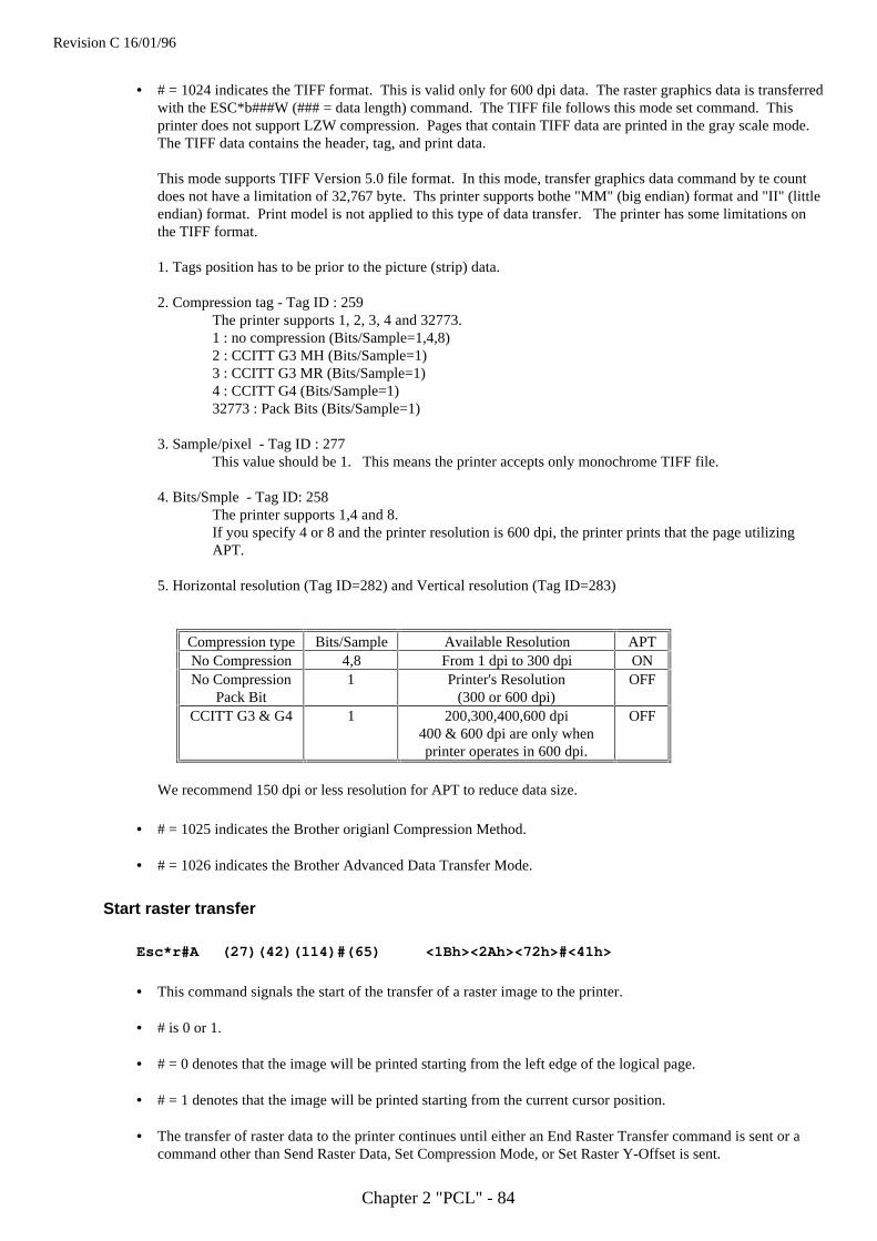
Revision C 16/01/96
Chapter 2 "PCL" - 84
• # = 1024 indicates the TIFF format. This is valid only for 600 dpi data. The raster graphics data is transferredwith the ESC*b###W (### = data length) command. The TIFF file follows this mode set command. Thisprinter does not support LZW compression. Pages that contain TIFF data are printed in the gray scale mode.The TIFF data contains the header, tag, and print data.
This mode supports TIFF Version 5.0 file format. In this mode, transfer graphics data command by te countdoes not have a limitation of 32,767 byte. Ths printer supports bothe "MM" (big endian) format and "II" (littleendian) format. Print model is not applied to this type of data transfer. The printer has some limitations onthe TIFF format.
1. Tags position has to be prior to the picture (strip) data.
2. Compression tag - Tag ID : 259The printer supports 1, 2, 3, 4 and 32773.1 : no compression (Bits/Sample=1,4,8)2 : CCITT G3 MH (Bits/Sample=1)3 : CCITT G3 MR (Bits/Sample=1)4 : CCITT G4 (Bits/Sample=1)32773 : Pack Bits (Bits/Sample=1)
3. Sample/pixel - Tag ID : 277This value should be 1. This means the printer accepts only monochrome TIFF file.
4. Bits/Smple - Tag ID: 258The printer supports 1,4 and 8.If you specify 4 or 8 and the printer resolution is 600 dpi, the printer prints that the page utilizing APT.
5. Horizontal resolution (Tag ID=282) and Vertical resolution (Tag ID=283)
Compression type Bits/Sample Available Resolution APTNo Compression 4,8 From 1 dpi to 300 dpi ONNo Compression
Pack Bit1 Printer's Resolution
(300 or 600 dpi)OFF
CCITT G3 & G4 1 200,300,400,600 dpi400 & 600 dpi are only whenprinter operates in 600 dpi.
OFF
We recommend 150 dpi or less resolution for APT to reduce data size.
• # = 1025 indicates the Brother origianl Compression Method.
• # = 1026 indicates the Brother Advanced Data Transfer Mode.
Start raster transfer
Esc*r#A (27)(42)(114)#(65) <1Bh><2Ah><72h>#<41h>
• This command signals the start of the transfer of a raster image to the printer.
• # is 0 or 1.
• # = 0 denotes that the image will be printed starting from the left edge of the logical page.
• # = 1 denotes that the image will be printed starting from the current cursor position.
• The transfer of raster data to the printer continues until either an End Raster Transfer command is sent or acommand other than Send Raster Data, Set Compression Mode, or Set Raster Y-Offset is sent.
Revision C 16/01/96
Chapter 2 "PCL" - 85
Send raster data
Esc*b#W<data> (27)(42)(98)#(87) <1Bh><2Ah><62h>#<57h>
• This command sends a single row of the raster image to the printer for printing.
• # signifies the number of bytes to be sent.
• If more data is transmitted than can be fitted onto one row of the specified raster area, the excess data will beignored.
Compress transfer graphics
Esc*b#C<image data> (27)(42)(98)#(67) <1Bh><2Ah><62h>#<43h>
• As a more efficient alternative to the Send Raster Data command, this command sends a single row of theraster image to the printer for printing, in a compressed form.
• # signifies the number of data bytes that the uncompressed row would consist of.
• Pairs of bytes describe the data which follows.
• If the MSB of the first byte of a pair is 1, the byte that follows the pair is repeated. The number held in theremaining fifteen bits of the byte pair is the number of times the data byte is repeated.
• If the MSB of the first byte of the pair is 0, the bytes that follow the pair are not repeated. The number held inthe remaining fifteen bits of the byte pair is the number of bytes of unrepeated raster data that follow.
• A raster row is made up of a sequence of byte pair-image data combinations.
End raster transfer
Esc*rB (27)(42)(114)(66) <1Bh><2Ah><72h><42h>
• This command signals the end of a transfer of a raster image to the printer.
• After execution of this command the cursor is positioned a distance of one raster row (at the last specifiednumber of dots per inch) down from the bottom of the raster area.
Esc*rC (27)(42)(114)(67) <1Bh><2Ah><72h><43h>
• This command signifies the end of the raster graphic data transfer and this is a modified version of the ESC*rB .
• After receiving this command, the printer resets the compression seed, compression mode, and left-graphicsmargin to 0.
• Also, the cursor is positioned a distance of one raster row (at the last specified number of dots per inch) downfrom the bottom of the raster data.
• This command resets the compression mode setting to 0.
• This command defaults the left graphics margin to 0.
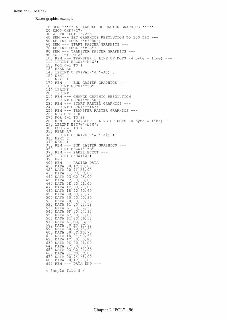
Revision C 16/01/96
Chapter 2 "PCL" - 86
Raster graphics example
10 REM ***** A EXAMPLE OF RASTER GRAPHICS *****20 ESC$=CHR$(27)30 WIDTH "LPT1:",25540 REM --- SET GRAPHICS RESOLUTION TO 300 DPI ---50 LPRINT ESC$+"*t300R";60 REM --- START RASTER GRAPHICS ---70 LPRINT ESC$+"*r1A";80 REM --- TRANSFER RASTER GRAPHICS ---90 FOR I=1 TO 28100 REM --- TRANSFER 1 LINE OF DOTS (4 byte = line) ---110 LPRINT ESC$+"*b4W";120 FOR J=1 TO 4130 READ A$140 LPRINT CHR$(VAL("&H"+A$));150 NEXT J160 NEXT I170 REM --- END RASTER GRAPHICS ---180 LPRINT ESC$+"*rB"190 LPRINT200 LPRINT210 REM --- CHANGE GRAPHIC RESOLUTION220 LPRINT ESC$+"*t75R";230 REM --- START RASTER GRAPHICS ---240 LPRINT ESC$+"*r1A";250 REM --- TRANSFER RASTER GRAPHICS ---260 RESTORE 410270 FOR I=1 TO 28280 REM --- TRANSFER 1 LINE OF DOTS (4 byte = line) ---290 LPRINT ESC$+"*b4W";300 FOR J=1 TO 4310 READ A$320 LPRINT CHR$(VAL("&H"+A$));330 NEXT J340 NEXT I350 REM --- END RASTER GRAPHICS ---360 LPRINT ESC$+"*rB"370 REM --- PAPER EJECT ---380 LPRINT CHR$(12);390 END400 REM --- RASTER DATA ---410 DATA 00,1F,E0,00420 DATA 00,7F,F8,00430 DATA 01,F0,3E,00440 DATA 03,C0,0F,00450 DATA 07,00,03,80460 DATA 0E,00,01,C0470 DATA 1C,38,70,E0480 DATA 18,70,70,60490 DATA 38,38,70,70500 DATA 30,00,00,30510 DATA 70,00,00,38520 DATA 61,00,02,18530 DATA 61,00,02,18540 DATA 6F,80,07,98550 DATA 67,80,07,D8560 DATA 61,80,06,18570 DATA 61,C0,0E,18580 DATA 70,E0,1C,38590 DATA 30,70,78,30600 DATA 38,3F,F0,70610 DATA 18,0F,C0,60620 DATA 1C,00,00,E0630 DATA 0E,00,01,C0640 DATA 07,00,03,80650 DATA 03,C0,0F,00660 DATA 01,F0,3E,00670 DATA 00,7F,F8,00680 DATA 00,1F,E0,00690 REM --- DATA END ---
< Sample file 8 >
Revision C 16/01/96
Chapter 2 "PCL" - 87
Vector graphicsFor large-scale graphic images it is more efficient to use vector graphics. In Laserjet 4 emulation mode you can setup the page area on which to print vector graphics images. The vector graphics capabilities of this HL Seriesprinter working in HP-GL/2 mode are described in the HP-GL/2 section of this manual.
Enter HP-GL/2 mode
Esc%#B (27)(37)#(66) <1Bh><25h>#<42h>
• This command enters HP-GL/2 graphics mode.
• # = 0 the cursor is positioned at the previous HP-GL/2 cursor position. If this is the first time you haveswitched to HP-GL/2 mode since switching the printer on, the cursor is placed at the origin of the HP-GL/2graphics window.
• # = 1 the cursor remains at its current position.
The picture frame
The PCL picture frame is the rectangular area of the page on which you can print graphic images. You canposition and size the picture frame to suit your requirements and achieve effects such as scaling or distortion ofvector graphics images.
The default picture frameThe default picture frame size and position is determined by the default logical page size and text length for eachgiven paper size.
Set picture frame anchor point
Esc*c0T (27)(42)(99)(48)(84) <1Bh><2Ah><63h><30h><54h>
• This command sets the anchor point (top left hand corner) of the picture frame to the current cursor position.
Set picture frame vertical size
Esc*c#Y (27)(42)(99)#(89) <1Bh><2Ah><63h>#<59h>
• This command sets the vertical size of the picture frame.
• # is the height of the picture frame in decipoints.
Set picture frame horizontal size
Esc*c#X (27)(42)(99)#(88) <1Bh><2Ah><63h>#<58h>
• This command sets the horizontal size of the picture frame.
• # is the width of the picture frame in decipoints.
Revision C 16/01/96
Chapter 2 "PCL" - 88
Specify vertical plot size
Esc*c#L (27)(42)(99)#(76) <1Bh><2Ah><63h>#<4Ch>
• This command specifies the height in inches of an imported image.
• # is the height of the image in inches.
• # can be in the range 0 to 32767 and can have up to four places of decimals.
• This command is only applicable to existing graphic images which are being imported from an application.
• The imported graphic will be scaled so that its height matches that of the HP-GL/2 graphics window.
Specify horizontal plot size
Esc*c#K (27)(42)(99)#(75) <1Bh><2Ah><63h>#<4Bh>
• This command specifies the width in inches of the image being imported.
• # is the width of the image in inches.
• # can be in the range 0 to 32767 and can have up to four places of decimals.
• This command is only applicable to existing graphic images which are being imported from an application.
• The imported graphic will be scaled so that its width matches that of the HP-GL/2 graphics window.
Revision C 16/01/96
Chapter 2 "PCL" - 89
Macros
The purpose of a macroA macro is a sequence of commands that you wish to execute. You can specify the command sequence anddownload it to the printer after which you can execute it with a single command. For example, you might wish todraw a raster image at the top of each page you print. Rather than sending the same sequence of commands everytime you print a new page, it is more efficient to define a macro to draw the image and store the macro in theprinter’s memory. Having done this, you can draw the picture on each page simply by running the macro, that is,with a single command.Like downloaded fonts, macros take up printer memory. To alleviate this, some macros are available on cartridgesthat can be plugged into the printer’s cartridge slots. A cartridge-based macro must have a unique ID number orelse you will not be able to access it. If a downloaded macro has the same ID number as a cartridge macro, allreferences to the ID number will be interpreted as references to the downloaded macro. To access the cartridgemacro you would first have to delete the downloaded macro.
Another method of storing Macros is uniquely available on the HL-10h/1260 printer. This is the use of PCMCIAformat memory cards type I or type III in the card slot of the printer. Macros can be saved to this card as requiredand then executed from the card. A delete facility is also included to allow the removal of macros when no longerrequired. The rules for identifying and calling Macros from this card are exactly the same as for cartridge storedMacros detailed above.
One macro can call another, however, only two levels of nesting are permitted.A printer reset will delete macros from the printer’s memory unless they have been explicitly designated aspermanent.
The PCL picture frame commands, the printer reset command and HP-GL/2 graphic language commands cannotbe invoked from within a macro.
Defining a macroTo define a macro you must first assign an ID number to it, then send to the printer a Start Macro Definitioncommand, the macro definition itself (consisting of a sequence of PCL commands) and finally an End MacroDefinition command.
Macro ID
Esc&f#Y (27)(38)(102)#(89) <1Bh><26h><66h>#<59h>
• This command assigns an identity number to a macro that is to be downloaded, or references an existing macroin the printer’s memory.
• # is the ID number of a macro. The ID number must be in the range 0-32767.
• If you specify the ID number of an existing macro and then download a new macro definition to the printer, thenew macro will overwrite the existing macro.
Start macro definition
Esc&f0X (27)(38)(102)(48)(89) <1Bh><26h><66h><30h><59h>
• This command signifies that the following commands constitute a macro definition.
Revision C 16/01/96
Chapter 2 "PCL" - 90
End macro definition
Esc&f1X (27)(38)(102)(49)(89) <1Bh><26h><66h><31h><59h>
• This command terminates the macro definition.
Running a macroMacros can be invoked in three different ways: they can be executed, called or enabled for overlay. When a macrois 'executed' it uses the current modified print environment. Any changes it makes to the environment arepermanent. A macro that is 'called' also uses the current modified print environment, however, any changes itmakes to the environment are discarded when the macro has performed its function. When a macro is 'enabled' foroverlay, the macro’s command sequence is performed as the final operation every time a page is printed. Overlaidmacros use the overlay environment. The overlay environment is a combination of the user default environmentand the modified print environment. This environment has effect only while the macro is running.
Page length Paper sourcePage size Number of copiesOrientation Cursor position stackRegistration
Execute macro
Esc&f2X (27)(38)(102)(50)(89) <1Bh><26h><66h><32h><59h>
• This command executes the macro whose ID number was specified most recently.
• Any changes made to the modified print environment during the execution of a macro, such as font selection ormargin settings, are retained after macro execution has been completed.
Call macro
Esc&f3X (27)(38)(102)(51)(89) <1Bh><26h><66h><33h><59h>
• This command calls the macro whose ID number was specified most recently.
• Any changes made to the modified print environment during a macro call, such as raster graphics settings, aretemporary and remain in effect only while the macro is running. They are not retained after the macro hasfinished.
Enable macro for overlay
Esc&f4X (27)(38)(102)(52)(89) <1Bh><26h><66h><34h><59h>
• This command overlays the macro whose ID number was specified most recently.
Disable macro for overlay
Esc&f5X (27)(38)(102)(53)(89) <1Bh><26h><66h><35h><59h>
• This command stops overlaying the macro whose ID number was specified most recently.
Revision C 16/01/96
Chapter 2 "PCL" - 91
Handling macros
Delete all macros
Esc&f6X (27)(38)(102)(54)(89) <1Bh><26h><66h><36h><59h>
• This command deletes all macros from the printer’s memory.
Delete all temporary macros
Esc&f7X (27)(38)(102)(55)(89) <1Bh><26h><66h><37h><59h>
• This command deletes all temporary macros from the printer’s memory. Temporary macros are those whichhave not been made permanent with the Esc&f10X command.
Delete macro
Esc&f8X (27)(38)(102)(56)(89) <1Bh><26h><66h><38h><59h>
• This command deletes from printer memory the macro whose ID number was specified most recently.
Make macro temporary
Esc&f9X (27)(38)(102)(57)(89) <1Bh><26h><66h><39h><59h>
• This command makes the macro whose ID number was specified most recently temporary (that is, it will not beretained if the printer is reset).
Delete all macros from PCMCIA memory card
Esc&f1030X (27)(38)(102)(49)(48)(51)(48)(89)<1Bh><26h><66h><31h><30h><33h><30h><59h>
• This command deletes all macros and all data from the installed PCMCIA memory card.
Delete macro from card
Esc&f1036X (27)(38)(102)(49)(48)(51)(54)(89)<1Bh><26h><66h><31h><30h><33h><36h><59h>
• This command delete the macro whose ID number was specified most recently from the installed PCMCIAmemory card.
Save macro into PCMCIA memory card
Esc&f1038X (27)(38)(102)(49)(48)(51)(56)(89)<1Bh><26h><66h><31h><30h><33h><38h><59h>
• This command saves the macro whose ID number was specified most recently into the installed PCMCIAmemory card.
Revision C 16/01/96
Chapter 2 "PCL" - 92
Make macro permanent
Esc&f10X (27)(38)(102)(49)(48)(89) <1Bh><26h><66h><31h><30h><59h>
• This command makes the macro whose ID number was specified most recently permanent (that is, it will beretained if the printer is reset).
Macro example
10 REM ***** A EXAMPLE OF A MACRO *****20 ESC$=CHR$(27)30 WIDTH "LPT1:",25540 REM --- RESET PRINTER ---50 LPRINT CHR$(27);"E":60 REM --- SET MACRO ID TO 0 ---70 LPRINT ESC$+"&f0Y";80 REM --- START MACRO DEFINITION ---90 LPRINT ESC$+"&f0X";100 REM --- SET CURSOR POSITION X=1800 DOT, Y=0 DOT ---110 LPRINT ESC$+"*p1800x0Y";120 REM --- SET FONT TO LETTER GOTHIC (18 DOTS WIDE) ---130 LPRINT ESC$+"(s0p16.66h8.5v0s0b130T";140 REM --- PRINT COMMENT ---150 LPRINT "Printed by this printer";160 REM --- SET CURSOR POSITION X=1790 DOT, Y=-40 DOT ---170 LPRINT ESC$+"*p1790x-40Y";180 REM --- PERFORM SHADING ---190 REM --- SET SHADING WIDTH TO 23 CHARACTERS + 20 DOTS ---200 LPRINT ESC$+"*c";23*18+20;"A";210 REM --- SET SHADING HEIGHT TO 30 DOTS ---220 LPRINT ESC$+"*c60B";230 REM --- DRAW SHADING PATTERN (5% GRAY SCALE) ---240 LPRINT ESC$+"*c5g2P";250 REM --- END MACRO DEFINITION ---260 LPRINT ESC$+"&f1X";270 REM --- MACRO OVERLAY ON (PRINT THE MESSAGE ON EVERY PRINTOUT) -- 280 LPRINT ESC$+"&f4X";290 REM --- SET FONT TO BROUGHAM 10 ---300 LPRINT ESC$+"(s0p10h12v0s0b128T";310 REM --- MACRO OVERLAY ON, PAPER EJECT ---320 LPRINT "MACRO OVERLAY ON"330 LPRINT CHR$(12);340 REM --- MACRO OVERLAY ON, PAPER EJECT ---350 LPRINT "MACRO OVERLAY ON"360 LPRINT CHR$(12);370 REM --- MACRO OVERLAY OFF (PRINT WITHOUT THE MESSAGE) ---380 LPRINT ESC$+"&f5X";390 REM --- MACRO OVERLAY OFF, PAPER EJECT ---400 LPRINT "MACRO OVERLAY OFF"410 LPRINT CHR$(12);420 END
Revision C 16/01/96
Chapter 2 "PCL" - 93
Execute data
The data saved in the PCMCIA card by using Printer's control panel "SAVE DATA" function can be printed bythe following command. It is also printed by the operation of Printer control panel.
EscCR!#E (27)(13)(33)#(69) <1Bh><0Dh><21h>#<45h>
• # indicates the DATA ID.
• Execute the data which is saved in the flash memory card or Hard Disk card.
• The printer uses the current environment when this command is executed.
• During execiting the data, it is possible to change the emulation or reset the printer.
• If this command is included on the last of the data which is saved by "SAVE DATA" operation from theprinter's control panel, the printer enters the permanent roop so that the saved data such as DEMO printingkeeps printing. To stop it, press the RESET key on the printer's control panel. This function is available onlyfor the Flash ROM card.
Revision C 16/01/96
Chapter 2 "PCL" - 94
AppleTalk Configuration
Esc&b#W[key]<sp>[value] (27)(38)(98)#(87)[Key](32)[value]<1Bh><26h><62h>#<57h>[Key]<20h>[value]
• # value can be from 0 to 32767.
• # stands for number of bytes in the data which is followed this command.
• [key] should be [RENAME], [JOB] or [TYPE].
• If the key is [RENAME], this command allows the printer to change the name field of AppleTalk namebinding protocol.
<ESC>&b#WRENAME<sp>printernameprintername should be specified with 1 to 31 characters.The character $00 to $FF (except for $00, @, :, *, =, $C5) can be used for printername.$00 is used for terminater.If invalid characters are used, this command is ignored.
• If the [key] is set to [JOB], this command changes the current job name.<ESC>&b#WJOB<sp>jobnameAll character from $00 to $FF can be used for jobname.jobname can have maximum 127 characters.
• If the [key] is set to [TYPE], this command allows the printer to change the type field of AppleTalk namebinding protocol.<ESC>&b#WTYPE<sp>devicetypedevicetype should be specified with 1 to 31 characters.The character $00 to $FF (except for $00, @, :, *, =, $C5) can be used for devicetype.$00 is used for terminater.
If invalid characters are used, this command is ignored.
MIO Video I/O port control
HL-1260 has only "VSREQ" signal for vertical syncronization signal to be sent to MIO port. This cause a littledelay of actual printing start after sending VSREQ signal, if the video controller have interrupt. This delay causesthe incorrect printing position vertically. To avoid the problem, the following command is useful.
EscCR!12340M (27)(13)(33)(49)(50)(51)(52)(48)(77)<1Bh><0Dh><21h><31h><32h><33h><34h><30h><4Dh>
• Laser diode drive port of video interface of MIO port is closed.
EscCR!12341M (27)(13)(33)(49)(50)(51)(52)(49)(77)<1Bh><0Dh><21h><31h><32h><33h><34h><31h><4Dh>
• Laser diode drive port of video interface of MIO port is opened.
EscCR!12342M (27)(13)(33)(49)(50)(51)(52)(50)(77)<1Bh><0Dh><21h><31h><32h><33h><34h><32h><4Dh>
• Laser diode drive port of video interface of MIO port is opened and send the print start command to printerengine immediately after sending the VSREQ signal.

Revision C 16/01/96
Chapter 2 "PCL" - 95
Status readback
Introduction
Status readback features are explained in this section. The printer sends a status response message after receiving arequest for its status by these commands. You can get the information as shown below from the printer.
- available printer(user) memory- current available fonts and symbol sets- the ID numbers of downloaded macros and user-defined patterns to verify their presence
The computer system must have a device driver for bi-directional communication to get the printers statusresponse. Bi-directional communication is supported on the HL-10h and HL-6V by the printer driver whichcomes with these machines.
Memory status request
You can identify the capacity of the user memory in the printer by using the memory status request. You candetermine whether to execute "downloading" or not, by knowing the available memory and thus avoid printermemory overrun errors.
Entity Status
You can request the printer to send the status of its entities. A font, symbol set, macro, or user-defined pattern inthe printer can be an entity. In order to request entity status, a position type and a position unit must be identifiedfirst and then the entity request command must be sent.
Location type is the memory positions that contain the entities. Memory positions are internal ROM, RAM,cartridges/cards, PCMCIA memory card and one additional position specified as "currently selected". Currentlyselected means the entity is active. However, "currently selected" can be applied only for fonts and user-definedpatterns.
Location unit means more specific position within the location type.
When the location type and unit are identified, you can request the status with the Inquire Status Readback Entitycommand. The entity (font, symbol set, macro, or user-defined pattern) is specified by this command and theprinter sends the response.
When an invalid request is sent, the printer sends an error response back.
Revision C 16/01/96
Chapter 2 "PCL" - 96
Status Response
If a status request (command) is received, the printer produces the response data. The printer accumulates this datain an I/O status buffer and saves the response in this buffer until a user reads it or you turn off the printer.
The printer clears the status responses when Printer resolution or Page protection or Emulation language ischanged.
The printer processes status requests and their related response in the order in which the printer receives them.
According to the internal printer operations, the number of responses the printer can accumulate is different. Ifyou use multiple applications or share the printer, you should read the response to a request before making a newrequest.
You should use the Echo command so that your applications request will synchronize with the printer's responses,because an earlier application might have requested a status and the printer might retain it.
A status response gets routed back to the I/O port that it was requested from.
Status response syntax
All of the status responses begin with "PCL", Carriage Return control code and a Line Feed control code. Theresponse is ended by a Carriage Return and a Line Feed control code. At the end of the transaction, statusresponses are ended by a Form Feed Control code. The fundamental syntax for the status response is as shownbelow.
PCL<CR> <LF>INFO TITLE<CR><LF>KEYWORDn=DATAn<CR><LF>KEYWORDn=DATAn<CR><LF>
.
. .<FF>
TITLE, KEYWORDn, and DATAn are strings which differ according to the status readback command beingoperated. One or more keyword lines related to the status readback response accompanies every status readbackresponse. Echo command response differs from this, and is as shown below.
PCL<CR><LF>ECHO ValueField<CR><LF><FF>
ValueField is the decimal number which comes from the Echo command value field.
For future printers, keywords might be added. Applications in which the status readback is used should be made todisregard lines with keywords they do not understand.
Revision C 16/01/96
Chapter 2 "PCL" - 97
Set Status Readback Location Type
ESC*s#T (27)(42)(115)#(84) <1Bh><2Ah><73h>#<54h>
This command determines the status location type to the value of #.The location type is used in association with the location unit in order to specify an entity location for a statusrequest.
• #=0 specifies an invalid location. When the printer receives an Inquire Entity Command, an error response isgenerated. This is the default value. When you execute a printer reset, this value is reset to 0.
• • # = 1 specifies the currently selected location.• • # = 2 specifies all locations.• • # = 3 specifies the printer's internal location.• • # = 4 specifies the downloaded entity.• • # = 5 specifies the user-installed card/cartridge
The location type setting is retained by the printer. When the printer does not send the set status readback locationtype command in order to change the setting for an entity request, then the printer uses the currently availablelocation type setting.
Set Status Readback Location Unit
ESC*s#U (27)(42)(115)#(85) <1Bh><2Ah><73h>#<55h>
• The status location unit is selected by the value of #.
• The printer uses the location unit in association with the location type in order to specify an entity location fora status request.
Type Unit0 - invalid location1 - currently selected location2 - all locations3 0 all internal entities4 0
12
all downloaded entitiesdownloaded entity as temporarydownloaded entity as permanent
5 01
n
All cartridge/cardsthe cartridge/card which has the highestpriority.the cartridge/card which has the lowestpriority
• When the location value is 0, 1 and 2, it ignores the unit value which might be set to any value. The defaultvalue is 0, and whenever you reset the printer, the value is reset to default value.
• The location unit setting is retained by the printer. If the printer does not send this command to change thesetting for an entity request, then it uses the currently available location units.
• The printer may set the location type and unit in order. It does not identify any invalid combinations until itreceives the inquire entity command. Hence, if the unit value is not in the correct range, it sets the unit to thevalue for a proper error response to be sent when the inquire entity command is received.
Revision C 16/01/96
Chapter 2 "PCL" - 98
Inquire Status Readback Entity
ESC*s#I (27)(42)(115)#(73) <1Bh><2Ah><73h>#<49h>
• Specifies the entity type and makes the printer produce a status response for the entity identified in the statusreadback location (type and unit).
Value entity type0 Font1 Macro2 User-defined Pattern3 Symbol set4 Font extended
Entity Status Response
The status response for an inquire status readback entity command differs according to the type of the requestedentity.
Font Response
Keywords returned from the printer depend on whether the printer font is a bitmap, unbound scalable, or boundscalable. Below is the list of keywords for a font request.
SELECT =SYMBOLSETS=LOCTYPE=LOCUNIT=
Below is an example of a font status response for inquire status command.
Internal, bitmap, LetterGothic 16.66Internal, unbound scalable, PcTennessee italicDownloaded, bound scalable, Portugal
Font status:
PCLINFO FONTSSELECT="<Esc>(8U<ESC>(s0p16.66h9.5v0s0b130T"SELECT="<Esc>(s1p__v1s0b4101T"SYMBOLSETS="0D, 0I, 0N, 0S, 0U, 1E, 1F, 1G, ..."SELECT="<Esc>(1U<Esc>(s1p__v0s0b5111T<Esc>(22X"
.
.
.
In a font status response, the "SELECT=" keyword line specifies the individual fonts. The font is identified by thisline by specifying the font selection characteristics such as symbol set, spacing, pitch, height, style, stroke weight,and typefaces. It returns the "SELECT=" for all font types.
In a status response, the five characters such as "<", "E", "s", "c", and "&>" represent an escape character.
Keywords following a "SELECT=" keyword mean the font specified by that "SELECT=" keyword.

Revision C 16/01/96
Chapter 2 "PCL" - 99
Bitmap Fonts
With regard to bitmap fonts, the printer returns the "SELECT=" line. This specifies the font selection features. Forinstance, the printer returns the printer's internal, bitmap, Roman-8 LetterGothic font as follows.
PCLINFO FONTSSELECT"=<Esc>(8U<Esc>(s0p16.66h8.5v0s0b130T"
Bound Scalable Fonts
With regard to bound scalable fonts, an underscore( "...s1p__v0s...,") in the "SELECT=" line means it is a boundscalable font. Also, the related features are indicated. Either the height or pitch is indicated depending uponwhether the font is proportional or fixed spaced. The printer, for instance, returns the printer's internal scalableSymbol font (proportionally spaced) as follows.
PCLINFO FONTSSELECT="<Esc>(19M<Esc>(s1p__v0s0b16901T"
Unbound Scalable Fonts
With regard to unbound fonts, the printer adds the "SYMBOLSETS=" keyword to specify the symbol sets whichcan be used, as the symbol sets can also be used with an unbound font, and there is no symbol set sequence in the"SELECT=" line. The printer, for instance, returns the printer's internal unbound scalable Brougham (medium,fixed spaced) font and Pc Tennessee (bold italic, proportional spaced) fonts as follows.
PCLINFO FONTSSELECT="<Esc>(s0p__h0s0b4099T"SYMBOLSETS="0D, 0I, 0N, 0U, 1E, 1F, 1G, ..."SELECT="<Esc>(s1p__v1s1s3b4101T"SYMBOLSETS="0D, 0I, 0N, 0S, 0U, 1E, 1F, 1G, ..."
Download Fonts
With regard to download fonts (bitmap, bound scalable or unbound scalable), the font ID number is included atthe end of the "SELECT=" line. For instance, the printer returns a downloaded bitmap Brougham with a font IDof 40 and a downloaded, unbound scalable, Dom Casual typeface with a font ID of 79 as follows.
PCLINFO FONTSSELECT="<Esc>(8U<Esc>(s0p11.00h12.0v0s0b3T<Esc>(40X"SELECT="<Esc>(s1p__v1s0b5259T<Esc>)79X"SYMBOLSETS="0D, 0D, 0N, 0S, 0U, 1E, 1F, 1G, ..."

Revision C 16/01/96
Chapter 2 "PCL" - 100
Location Type 1 (currently selected) Font
With regard to a status location type 1 (currently selected) font, the printer returns a single font, the printer fontwhich is currently selected. The following are the keywords and data returned.
The printer returns the "LOCTYPE=" and "LOCUNIT=" after the "SELECT=" line for every font.
"SELECT=" line changes for bound and unbound scalable fonts.
For all scalable fonts, the actual size (height or pitch ) is indicated instead of the underscores.
For unbound scalable fonts, the symbol set which is bound to the font at present is indicated.
Forall fonts, when the font is a secondary font, ")" replace the "(" characters in the "SELECT=" line.
"LOCTYPE=" specifies the location type of the font which is selected at present. The value field of the Set StatusReadback Type command is related to the value returned.
"LOCUNIT=" specifies the location unit of the font which is selected at present. The value field of the Set StatusReadback Unit command is related to the value returned.
For instance, if the printer font which is selected at present is a bold 12 point Presentation bitmap font which isselected from a cartridge, and a font entity request with the location type set to 1 is produced, the response will bereturned as follows.
PCLINFO FONTSSELECT="<Esc>(2U<Esc>(s0p10.00h12.0v0s3b11T"LOCTYPE=5LOCUNIT=1
For instance, suppose the printer font which is selected at present is unbound scalable Dom Casual font with thefeatures below:
downloaded (font ID of 78)temporaryRoman-8(specified for printing)secondary font18 point
When an entity request is produced with the location type set to 1(selected at present), it returns the responsebelow.
PCLINFO FONTSSELECT="<Esc>)8U<Esc>)s1p18.00v1s0b4148T<Esc>)78X"LOCTYPE=4LOCUNIT=1
Revision C 16/01/96
Chapter 2 "PCL" - 101
Font Extended Response
The font extended response supplies a method to return the name and internal ID number of the font as well as the"SELECT=" line. It is the same as a font status response since "SELECT=", "SYMBOLSETS=", "LOCTYPE=",and "LOCUNIT=" are returned in the same way. With regard to a font extended request, it returns the twoadditional keywords, "DEFID=" and "NAME=" as follows.
"DEFID" specifies the internal ID number of the font which is shown on the test print ( font list ). This is thenumber which is used to select the font as the default font from the control panel of printer or from PJL. The"DEFID=" number is made of two parts, which are a location and an ID number. The locations which are likelyare as follows;
I - InternalC - Cartridge (printer with single cartridge)Cn - Cartridge (printer with multiple cartridge/card when n is specified by printer.)S - Permanent download fonts
For temporary download fonts, it returns "DEFID=NONE" because temporary download fonts do not have aninternal ID number.
The printer assigns the internal ID number of the temporary download font with the Font ID (ESC*c#D)command. This internal ID number differs from the downloaded ID number assigned to a downloaded font.
It returns "NAME=" only for font extended status requests. The name of the font is the same as shown on the fontprintout.
For instance, it returns the font extended response for the printer's internal bitmap LetterGothic font and adownloaded unbound Portugal temporary font as follows.
PCLINFO FONTS EXTENDEDSELECT="<Esc>(8U<Esc>(s0p10.00h12.0v0s0b0T"DEFID="I 45"NAME="Line Printer"SELECT="<Ec>(s1p__v1s3b4111T<Esc>(7X"SymbolSETS="0D, 0I, 0N, 0S, 0U, 1E, 1F, 1G,..."DEFID=NONENAME="CG Palacio BdIt"SELECT="......
For instance, a font extended response with the location type set to 1( selected at present ) where the font which isselected at present is the internal Pc Tennessee (18 point identified for printing) bold, returns the response asfollows.
PCLINFO FONTS EXTENDEDSELECT="<Esc>(8U<Esc>(s0p18.00h0s3b4101T"DEFID="<Esc>(8U<Esc>s0p18.000s3b4101T"DEFID="I 2"NAME="PcTennessee Bd"LOCTYPE=1LOCUNIT=1
Revision C 16/01/96
Chapter 2 "PCL" - 102
Macro Response
The status response for macros indicates all of the macro IDs ("IDLIST=") for the macros in a particular location.
Status location type 1( selected at present ) is an ineffective location for macros and an error is returned.
A macro status response may be shown as follows.
PCLINFO MACROSIDLIST="1, 3, 8, 29, 32"
Use-Defined Pattern Response
The status response of user-defined patterns indicates all of the user-defined patterns and all of the user-definedpattern IDs ("IDLIST") for the patterns in a particular location.
A user-defined pattern response may be shown as follows.
PCLINFO PATTERNIDLIST="1, 2, 9, 13, 27, 456"
When the location type is specified to 1 (selected at present), "LOCTYPE=" and "LOCUNIT=" lines are added.
It returns the "LOCTYPE=" only for a status location type 1 requirement. It specifies the location type of thepattern which is selected at present.
It returns the "LOCUNIT=" only for a status location type 1 requirement. It specifies the location unit of thepattern which is selected at present.
A user-defined pattern response for the pattern selected at present may be shown as follows.
PCLINFO PATTERNSIDLIST="88"LOCTYPE=4LOCUNIT=2
When the pattern selected at present is set to one of the internal HP-specified patterns, there is no numberavailable and it returns the response "ERROR=NONE".
PCLINFO PATTERNSERROR=NONE
Revision C 16/01/96
Chapter 2 "PCL" - 103
Symbol Set Response
The symbol set response indicates all of the symbol set IDs ("IDLIST") for all of the symbol sets in the identifiedlocation. There can be bound and unbound scalable fonts in the identified location (type and unit).
A symbol set response may be shown as follows.
PCLINFO SYMBOLSETSIDLIST="0U, 2K, 8M, 11U"
Status location type 1 (selected at present) is an incorrect location for unbound font symbol sets and returns anerror.
Example responses in this section for "SYMBOLSETS=" do not indicate the complete list of symbol sets whichare available internally, but only a partial list . The internal symbol sets depend on the printer and might differaccording to the printer.
Entity Error Codes
When an out-of-range value exists in the command value fields, or when the entity is not supported or does notexist, or the request is inadequate, the printer replies with one of four likely errors as follows:
Invalid EntityInvalid LocationNoneInternal Error
ERROR=INVALID ENTITY
When the identified entity type is not in the range or not supported, it returns an invalid entity error.
PCLINFO ENTITYERROR=INVALID ENTITY
ERROR=INVALID LOCATION
When the entity type is correct, but the location ( the type, the unit, or the combination) is not, or when theidentified device is not installed, it returns an invalid location error.
PCLINFO FONTSERROR=INVALID LOCATION
ERROR=NONE
When the entity type and location are correct, but there are not any entities of the identified type in the location, orwhen the type is not correct for the identified entity, it generates the NONE error response.
PCLINFO SYMBOLSETSERROR=NONE
ERROR=INTERNAL ERROR
The status response for some requirements could be quite big. When status replies are requested, it returns an internal error ifthe printer runs out of memory as follows:
PCLINFO SYMBOL SETSERROR=INTERNAL ERROR
Revision C 16/01/96
Chapter 2 "PCL" - 104
Free Space Command
ESC*s1M (27)(42)(115)(48)(77) <1Bh><2Ah><73h><31h><4Dh>
The amount of memory which is free for use is returned by this command. Two values are returned: the totalamount of free memory and the largest block of free memory.
When you send a value other than 1, an error ( "ERROR = INVALID UNIT" )is returned.
The Free Space command is sent to check the free memory space and you can acknowledge whether the printerhas enough memory for a job or not before you execute your job. Also you can check the amount of memory whichan entity or any other data used.
Free memory space will always be changing during different printing conditions.*** For example, when the printer receives print data, it is stored in the printer memory. So, the freespace in the printer memory becomes smaller. After the data is printed, the printer memory becomesempty, so the free space becomes larger again.
Certain action is needed when you decide there is not enough memory to hold the data to be downloaded.
Font Cache
In order to print characters from a scalable font, the printer changes the scalable character outlines into sizedbitmaps. These bitmapped characters are produced on a character-by-character basis and produced bitmappedcharacters are stored in memory. As it prints more pages using more fonts, more memory is consumed by thebitmaps. The bitmap characters used on the first page of a job can stay in memory till the end of a job. Thesestored bitmap characters are known as the font cache.
If a Brother HL-10h printer encounters a memory low condition, all of the font cache is automatically deleted.Also, font cache and temporary entities can be cleared by a Printer Reset command.
Memory Status Response
The total available memory is specified by "TOTAL=" and the largest continuous block size of available memoryis specified by "LARGEST=".
PCLINFO MEMORYTOTAL = 10000LARGEST = 3500
Memory Error Response
When the value field of the free memory command is out of range, the response for this command would be asfollows;
PCLINFO MEMORYERROR = INVALID UNIT
Revision C 16/01/96
Chapter 2 "PCL" - 105
Flush All Pages Command
ESC&r#F (27)(38)(114)#(70) <1Bh><26h><72h>#<46h>
This command suspends accepting data from a PC and clears the user memory.
• #=0 suspends receiving data and ejects all complete data. Incompleted data remains in the printers memory.
• #=1 suspends receiving data and ejects all data remaining in the printer memory.
Echo Command
ESC*s#X (27)(42)(115)#(88) <1Bh><2Ah><73h>#<58h>
This command is used to distinguish each request and response. In networking/sharing environments, somerequests may be sent from a number of PCs to one printer. This command sends the user selected value to theprinter and the printer can return the same value. Adding this command before the status request command allowsthis echo value to distinguish the corresponding status response.
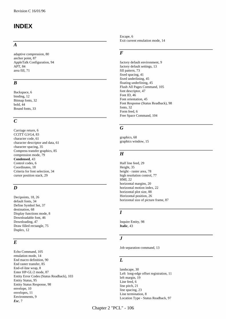
Revision C 16/01/96
Chapter 2 "PCL" - 106
INDEX
A
adaptive compression, 80anchor point, 87AppleTalk Configuration, 94APT, 84area fill, 71
B
Backspace, 6binding, 12Bitmap fonts, 32bold, 44Bound fonts, 33
C
Carriage return, 6CCITT G3/G4, 83character code, 61character descriptor and data, 61character spacing, 35Compress transfer graphics, 85compression mode, 79Condensed, 43Control codes, 6Coordinates, 18Criteria for font selection, 34cursor position stack, 29
D
Decipoints, 18, 26default fonts, 34Define Symbol Set, 37destination, 68Display functions mode, 8Downloadable font, 46Downloading, 47Draw filled rectangle, 75Duplex, 12
E
Echo Command, 105emulation mode, 14End macro definition, 90End raster transfer, 85End-of-line wrap, 8Enter HP-GL/2 mode, 87Entity Error Codes (Status Readback), 103Entity Status, 95Entity Status Response, 98envelope, 10envelopes, 11Environments, 9Esc, 7
Escape, 6Exit current emulation mode, 14
F
factory default environment, 9factory default settings, 13fill pattern, 73fixed spacing, 41fixed underlining, 45floating underlining, 45Flush All Pages Command, 105font descriptor, 47Font ID, 46Font orientation, 45Font Response (Status Readback), 98fonts, 32Form feed, 6Free Space Command, 104
G
graphics, 68graphics window, 15
H
Half line feed, 29Height, 35height - raster area, 78high resolution control, 77HMI, 22horizontal margins, 20horizontal motion index, 22horizontal plot size, 88Horizontal position, 26horizontal size of picture frame, 87
I
Inquire Entity, 98Italic , 43
J
Job separation command, 13
L
landscape, 30Left long-edge offset registration, 11left margin, 19Line feed, 6line pitch, 21line spacing, 23Line termination, 8Location Type - Status Readback, 97
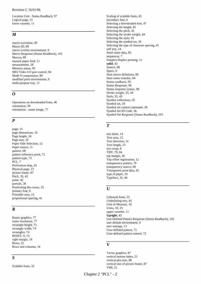
Revision C 16/01/96
Chapter 2 "PCL" - 2
Location Unit - Status Readback, 97Logical page, 15lower cassette, 11
M
macro execution, 90Macro ID, 89macro overlay environment, 9Macro Response (Status Readback), 102Macros, 89manual paper feed, 11measurement, 18Memory status, 95MIO Video I/O port control, 94Mode 9 compression, 80modified print environment, 9multi-purpose tray, 11
O
Operations on downloaded fonts, 46orientation, 30orientation - raster image, 77
P
page, 15page dimensions, 16Page length, 24Page size, 10Paper Side Selection, 12Paper source, 11pattern, 68pattern reference point, 72pattern type, 73PCL, 7Perforation skip, 24Physical page, 15picture frame, 87Pitch, 35, 42point, 42portrait, 30Positioning the cursor, 25primary font, 6Printable area, 15proportional spacing, 41
R
Raster graphics, 77raster resolution, 77rectangle height, 75rectangle width, 74rectangles, 74RESET, 9, 13right margin, 19Rows, 25Rows and columns, 18
S
Scalable fonts, 32
Scaling of scalable fonts, 43secondary font, 6Selecting a downloaded font, 47Selecting the height, 42Selecting the pitch, 42Selecting the stroke weight, 44Selecting the style, 43Selecting the symbol set, 39Selecting the type of character spacing, 41self test, 14Send raster data, 85sequences, 7Simplex/Duplex printing, 12solid, 43Source, 68Space, 6Start macro definition, 89Start raster transfer, 84Status readback, 95Status Response, 96Status response syntax, 96Stroke weight, 35, 44Style, 35, 43Symbol collections, 35Symbol set, 34Symbol set control command, 39Symbol Set ID Code, 36Symbol Set Response (Status Readback), 103
T
test sheet, 14Text area, 15Text direction, 31Text length, 23text wrap, 8TIFF, 79, 84top margin, 20Top offset registration, 12transparency pattern, 70transparency source, 69Transparent print data, 45type of paper, 10Typeface, 35, 44
U
Unbound fonts, 33Underlining text, 45Unit of Measure, 18Units, 18, 25upper cassette, 11Upright , 43Use-Defined Pattern Response (Status Readback), 102user default environment, 9user settings, 13User-defined pattern, 71User-defined pattern control, 72
V
Vector graphics, 87vertical motion index, 21vertical plot size, 88vertical size of picture frame, 87VMI, 21
Revision C 16/01/96
Chapter 2 "PCL" - 3
W
width - raster area, 78
Y
y-offset (raster), 79
Revision C 16/01/96
Chapter 3 "PJL" - 1
Chapter 3
PJL
Printer Job Language
Revision C 16/01/96
Chapter 3 "PJL" - 2
TABLE OF CONTENTS
TABLE OF CONTENTS ......................................................................................................................................... 2
1. INTRODUCTION ................................................................................................................................................ 4
1.1 ABOUT PJL................................................................................................................................................... 41.2. IN CASE OF USING PJL WITH NON-PJL PRINTER............................................................................................. 51.3. PJL SYNTAX AND FORMAT........................................................................................................................... 61.4. VARIABLES.................................................................................................................................................. 71.5. INVALID COMMANDS.................................................................................................................................... 7
2. HOW TO USE PJL .............................................................................................................................................. 8
2.1. OVERVIEW................................................................................................................................................... 82.2. PJL JOB REQUIREMENT................................................................................................................................ 8
3 COMMAND GROUP ............................................................................................................................................ 9
4. KERNEL COMMANDS .....................................................................................................................................10
4.1. INTRODUCTION...........................................................................................................................................104.2. UEL COMMAND .........................................................................................................................................104.3. EXECUTE COMMAND ................................................................................................................................114.4. ENTER COMMAND .....................................................................................................................................114.5. COMMENT COMMAND..............................................................................................................................124.6. PRINTER LANGUAGE SWITCHING .................................................................................................................13
5. JOB SEPARATION COMMENTS ....................................................................................................................14
5.1. INTRODUCTION...........................................................................................................................................145.2. JOB COMMAND ..........................................................................................................................................145.3. EOJ COMMAND ..........................................................................................................................................15
6. ENVIRONMENT COMMANDS ........................................................................................................................17
6.1. INTRODUCTION...........................................................................................................................................17Print environment ....................................................................................................................................17PJL reset conditions.................................................................................................................................18Remember about environments.................................................................................................................19PJL environment variables.......................................................................................................................19
6.2. VARIABLES.................................................................................................................................................20Variables for HL-10h...............................................................................................................................20Variables for HL-660...............................................................................................................................22Variables for HL-1260.............................................................................................................................26
6.3. DEFAULT COMMAND ...................................................................................................................................296.4. INITIALIZE COMMAND ..................................................................................................................................306.5. RESET COMMAND........................................................................................................................................316.6. SET COMMAND............................................................................................................................................32
Revision C 16/01/96
Chapter 3 "PJL" - 3
7. STATUS READBACK COMMANDS ................................................................................................................33
7.1. INTRODUCTION...........................................................................................................................................33Synchronization with the printer...............................................................................................................33Basic Format of Status Readback Responses ............................................................................................33
7.2. INQUIRE COMMAND ....................................................................................................................................347.3. DINQUIRE COMMAND...............................................................................................................................367.4. ECHO COMMAND ......................................................................................................................................387.5. INFO COMMAND ........................................................................................................................................39
ID Category .............................................................................................................................................40CONFIG Category...................................................................................................................................40MEMORY Category .................................................................................................................................42STATUS Category....................................................................................................................................43VARIABLES Category..............................................................................................................................43USTATUS Category.................................................................................................................................45
7.6. USTATUS COMMAND ................................................................................................................................47Device Variable .......................................................................................................................................48JOB Variables..........................................................................................................................................49PAGE Variables.......................................................................................................................................49TIMED Variable......................................................................................................................................50
7.7. USTATUSOFF COMMAND .........................................................................................................................517.8. JOB RECOVERY..........................................................................................................................................51
8. DEVICE ATTENDANCE COMMANDS ...........................................................................................................52
8.1. INTRODUCTION...........................................................................................................................................528.2. RDYMSG COMMAND.................................................................................................................................538.3. OPMSG COMMAND ....................................................................................................................................548.4. STMSG COMMAND ....................................................................................................................................55
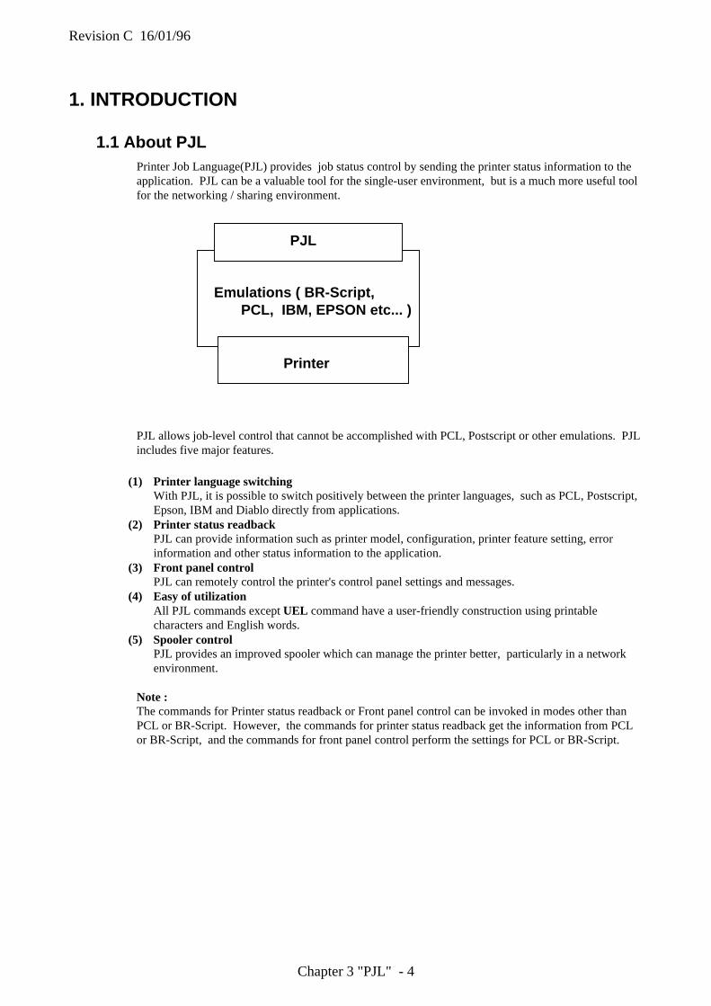
Revision C 16/01/96
Chapter 3 "PJL" - 4
1. INTRODUCTION
1.1 About PJLPrinter Job Language(PJL) provides job status control by sending the printer status information to theapplication. PJL can be a valuable tool for the single-user environment, but is a much more useful toolfor the networking / sharing environment.
Emulations ( BR-Script,PCL, IBM, EPSON etc... )
PJL allows job-level control that cannot be accomplished with PCL, Postscript or other emulations. PJLincludes five major features.
(1) Printer language switchingWith PJL, it is possible to switch positively between the printer languages, such as PCL, Postscript,Epson, IBM and Diablo directly from applications.
(2) Printer status readbackPJL can provide information such as printer model, configuration, printer feature setting, errorinformation and other status information to the application.
(3) Front panel controlPJL can remotely control the printer's control panel settings and messages.
(4) Easy of utilizationAll PJL commands except UEL command have a user-friendly construction using printablecharacters and English words.
(5) Spooler controlPJL provides an improved spooler which can manage the printer better, particularly in a networkenvironment.
Note :The commands for Printer status readback or Front panel control can be invoked in modes other thanPCL or BR-Script. However, the commands for printer status readback get the information from PCLor BR-Script, and the commands for front panel control perform the settings for PCL or BR-Script.
Printer
PJL
Revision C 16/01/96
Chapter 3 "PJL" - 5
1.2. In case of using PJL with non-PJL PrinterOur resent printer models HL-10h, HL-600 series, HL-660 and HL-1260 support PJL, however, earliermodels do not . If the PJL commands are sent to a non-PJL printer, the printer acts as follows;
PCL JobsFor a PCL printer which does not support the PJL language, the PJL command is printed as ASCIItext until initial PCL printer reset command (<ESC>E) is received. After receiving the PCL resetcommand, the printer ejects a page and proceeds with the PCL print job on a new page.The print job is possibly followed by more printed PJL commands.Without the PCL reset command, the PJL commands are printed as ASCII text on the same page asthe PCL print job.
Postscript JobsFor Postscript printers, when the printer receives a PJL command, a Postscript error is reported. ThePostscript job is discarded.
Other Printer LanguagesAccording to the active emulation, the PJL command is understood differently. To avoid theproblem, you should not use PJL commands on any non-PJL printer.
Revision C 16/01/96
Chapter 3 "PJL" - 6
1.3. PJL Syntax and Format
Syntax :<For Example>
@PJL ENTER LANGUAGE = emulation [<CR>]<LF>
@PJL PJL PrefixENTER Command nameLANGUAGE Option name@PJL ENTER LANGUAGE Enter this portion verbatim[ ] The words in brackets [ ... ] indicates optional parameters. You
should not type the brackets themselves in the command.< .. > The words in < .. > indicates a control code character<LF> Required line feed
< HT > Horizontal tab character (ASCII 9)< LF > Line feed character ( ASCII 10 )< CR > Carriage Return ( ASCII 13 )< SP > Space ( ASCII 32 )< ESC > Escape ( ASCII 27 )< FF > Form Feed ( ASCII 12 )< WS > White space which consists of some < SP >
and < HT >< words > Printable characters
Format :PJL commands have 4 types of format as shown below.
Format 1<ESC>%-12345XThis format is only used for Universal Exit Language(UEL) command.
Format 2@PJL[<CR>]<LF>This format allows a PJL line without a command, and is used to break several PJL command linesvisually, to make it easier to see the PJL command lines.
Format 3@PJL command [<words>] [<CR>] <LF>This format is used only for the COMMENT and ECHO commands.
Format 4@PJL command [command modifier : value] option=value[<CR>]<LF>
This format is used for all other PJL commands.
PJL Syntax Rules :PJL Syntax should be written according to the following rules.* " @PJL" must be uppercase. The other words of a PJL command are not case-sensitive.* Spacing between characters consists of one or more of either the space character (ASCII 32) or the
horizontal tab character(ASCII 9).* White space should be placed as follows, depending on the location within the command.
- White space should be placed between @PJL and the PJL command name, and between the PJLcommand and command modifiers.
- If a white space is placed in any other place in a command, it is optional.- If a white space is not placed between two portions of a command, the command is not valid.
Revision C 16/01/96
Chapter 3 "PJL" - 7
1.4. VariablesPJL can use alphanumeric, numeric variables and strings.
Alphanumeric variablesThe first character must always be a character in any combination of letters and digits Lettersconsists of the uppercase characters (ASCII 65-90) and lowercase characters (ASCII 97-122).Digits consists of the numbers 0-9 (ASCII 48-57).
<Example>Brother2245
Numeric variablesThe number consists of some digits with one optional decimal point and an optional + or - signpreceding the first digit.
<Example>0.1234-123.4+123.0
<Wrong>
+.05-.05
StringsStrings consist of any combination of characters from ASCII 32 to 255, plus ASCII 9, exceptASCII 34 (quotation marks), which are used to define the start and end of a string.
<Example>"Print Job KKK""This is a sample string"
1.5. Invalid CommandsThere are two general types of invalid commands. Each type operates differently.Syntax errors include :
• unrecognized command and command modifier• strings which are missing quotation marks• numeric values which are missing digits before the decimal point
etc ....
Syntax errorsCommands received with Syntax errors cause the printer to ignore the entire PJL command.
Syntax warning and semantic warningSyntax warnings and semantic warnings are issued for commands which include unsupported options,values which are out of range, or wrong or missing commands, etc. When the printer receivescommands which would create a syntax warning or semantic warning, it operates the command as longas possible, however, the portion of the command which would create a warning is ignored.
Revision C 16/01/96
Chapter 3 "PJL" - 8
2. HOW TO USE PJL
2.1. OverviewPJL resides "above" printer languages such as Postscript and PCL. Each job can be distinguished fromthe other jobs by PJL, and it can switch between PJL commands and printer language commands foreach job.
PJL Code PCL Job PJL Code Postscript JobPJL Code
2.2. PJL Job RequirementSome conditions are required in order for PJL commands to work correctly. Jobs which follow theseconditions will work correctly with a PJL printer in single user and network environments.
* All PJL jobs must begin and end with a UEL command.* The @PJL prefix must be placed immediately after the UEL command which starts PJL jobs, and
can be followed by <CR> and <LF>. Characters, including control characters, must not be placedbetween the UEL command and the @PJL prefix.
* Nothing must be placed after the UEL command which ends a PJL job.* <LF> is required to terminate all PJL commands. <CR> can be placed before <LF>, however,
<CR> is optional and is ignored.* Blank lines must not exist. If a blank line is required, the @PJL <CR><LF> line can be used.
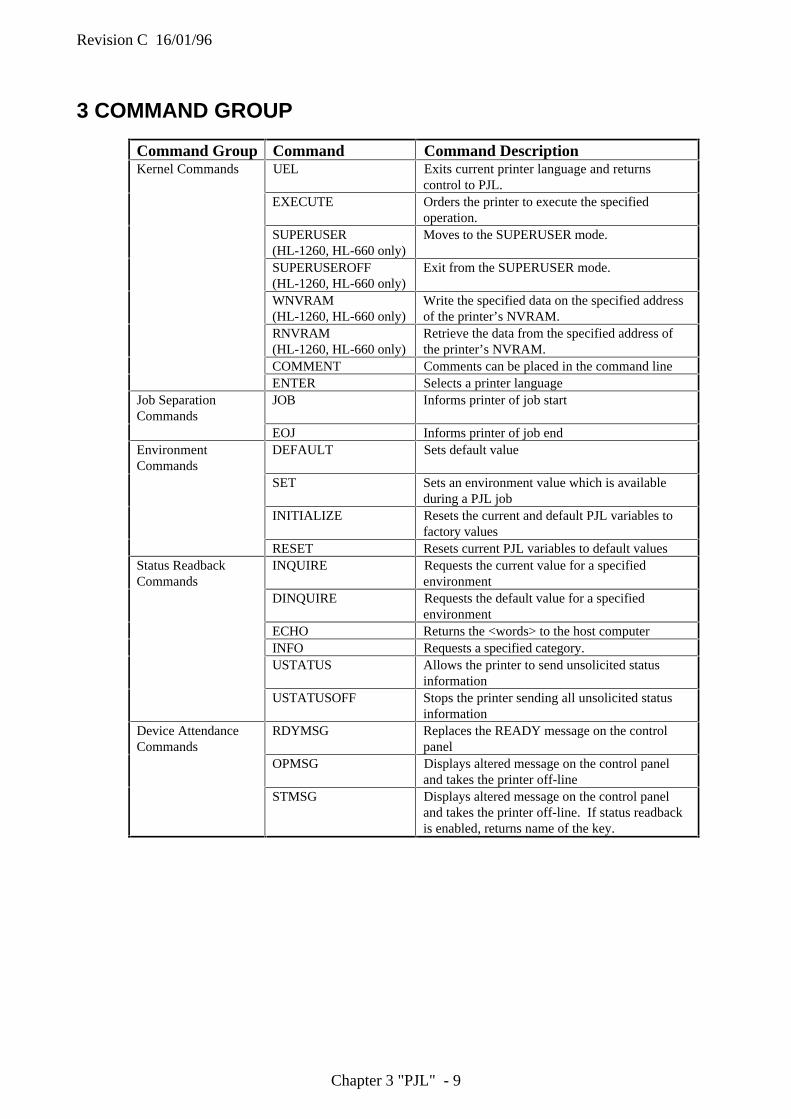
Revision C 16/01/96
Chapter 3 "PJL" - 9
3 COMMAND GROUP
Command Group Command Command DescriptionKernel Commands UEL Exits current printer language and returns
control to PJL.EXECUTE Orders the printer to execute the specified
operation.SUPERUSER(HL-1260, HL-660 only)
Moves to the SUPERUSER mode.
SUPERUSEROFF(HL-1260, HL-660 only)
Exit from the SUPERUSER mode.
WNVRAM(HL-1260, HL-660 only)
Write the specified data on the specified addressof the printer’s NVRAM.
RNVRAM(HL-1260, HL-660 only)
Retrieve the data from the specified address ofthe printer’s NVRAM.
COMMENT Comments can be placed in the command lineENTER Selects a printer language
Job SeparationCommands
JOB Informs printer of job start
EOJ Informs printer of job endEnvironmentCommands
DEFAULT Sets default value
SET Sets an environment value which is availableduring a PJL job
INITIALIZE Resets the current and default PJL variables tofactory values
RESET Resets current PJL variables to default valuesStatus ReadbackCommands
INQUIRE Requests the current value for a specifiedenvironment
DINQUIRE Requests the default value for a specifiedenvironment
ECHO Returns the <words> to the host computerINFO Requests a specified category.USTATUS Allows the printer to send unsolicited status
informationUSTATUSOFF Stops the printer sending all unsolicited status
informationDevice AttendanceCommands
RDYMSG Replaces the READY message on the controlpanel
OPMSG Displays altered message on the control paneland takes the printer off-line
STMSG Displays altered message on the control paneland takes the printer off-line. If status readbackis enabled, returns name of the key.
Revision C 16/01/96
Chapter 3 "PJL" - 10
4. KERNEL COMMANDS
4.1. IntroductionThis section explains three PJL command, UEL , ENTER and COMMENT . These commands providethe minimum set of tools to operate job control.
UEL command (Universal Exit Command)ENTER commandCOMMENT command
4.2. UEL Command
The Universal Exit Command causes the printer to exit the current printer language and sets the printerinto PJL mode.
Syntax :<ESC>%-12345X
• The UEL command is a data stream sequence.• The UEL command indicates to the current printer language to finish a job. If PJL is available, PJL
commands which have not yet been executed are cancelled and the printer is ready to accept the nextPJL command.
• The UEL command must be placed in the first and last position of all PJL job command sequences.• Printers which have an Auto I/O switching feature can use the UEL command in order to settle job
boundaries.• The @PJL prefix which is placed at the beginning of a PJL job must follow immediately after the
UEL command .• If the printer receives codes other than the PJL prefix, it enables the default printer language and
prints the job.• ENTER command should be used in order to specify the printer language.
Example :<ESC>%-12345X@PJL<CR><LF>@PJL ENTER LANGUAGE = PCL <CR><LF><ESC>E.......PCL JOB........<ESC>E<ESC>%-12345X
Revision C 16/01/96
Chapter 3 "PJL" - 11
4.3. EXECUTE command
The EXECUTE command orders the printer to execute the specified operation.This command is supported only by HL-660 series printer.
Syntax :@PJL ENTER operation [<CR>]<LF>
Parameters :• • operation
SHUTDOWN : The printer goes into the sleep mode.DEMOPAGE : The printer prints the demo page.RESIFONT : The printer prints the list of resident fonts.PERMFONT: The printer prints the list of permanent download fonts.PRTCONFIG: The printer prints the list of printer settings.
• If the printer receives this command, it immediately executes the specified operation.
• If this command specifies the operation which is not supported, this command is ignored.
Example :<ESC>%-12345X@PJL<CR><LF>@PJL EXECUTE DEMOPAGE <CR><LF><ESC>%-12345X
4.4. ENTER command
The ENTER command specifies which emulation the printer uses to print data.
Syntax :@PJL ENTER LANGUAGE = emulation [<CR>]<LF>
Parameters :• • emulation
The valuables varies according to your printer model.
• The ENTER command must be placed immediately before print data.
• The specified emulation will be used immediately after the terminator <LF> of the ENTERcommand.
• If the printer does not receive the ENTER command, it uses the default printer language which isset by the control panel or the printer language which is set by SET PERSONALITY command.
• In the case that the printer emulation is selected by the ENTER command, the printer must switchto the defined printer language.
• If this command specifies an emulation which is not supported, data after this command is ignoreduntil the next UEL command.
Revision C 16/01/96
Chapter 3 "PJL" - 12
Example :<ESC>%-12345X@PJL<CR><LF>@PJL ENTER LANGUAGE = PCL <CR><LF><ESC>E.......PCL JOB........<ESC>E<ESC>%-12345X@PJL COMMENT Start of Postscript job <CR><LF>@PJL ENTER LANGUAGE = POSTSCRIPT <CR><LF>%!PS-ADOBE......Postscript JOB.....^D<ESC>%-12345X@PJL COMMENT End of Postscript job <CR><LF><ESC>%-12345X
4.5. COMMENT command
The COMMENT command is used to add an information line, such as an explanation for the PJLcommand.
Syntax :@PJL COMMENT remarks [<CR>]<LF>
Parameters :• remarks
Printable character(ASCII 33-255 and White space which contains <HT> and <SP>)
• The COMMENT command is helpful for placing an explanation of a PJL command.
• The COMMENT command can be placed on the PJL line anywhere between the UEL commandand the ENTER command.
• The COMMENT command is terminated by <LF>.
• Comments can only be one line long. If you wish to add more text, start a new comment line.
Example :<ESC>%-12345X@PJL<CR><LF>@PJL COMMENT -----------------------------<CR><LF>@PJL COMMENT -- PCL & PS JOB --<CR><LF>@PJL COMMENT -----------------------------<CR><LF>@PJL <CR><LF>@PJL SET RET = ON <CR><LF>@PJL ENTER LANGUAGE = PCL <CR><LF><ESC>E.......PCL JOB........<ESC>E<ESC>%-12345X@PJL<CR><LF>@PJL COMMENT Start of Postscript job <CR><LF>@PJL ENTER LANGUAGE = POSTSCRIPT <CR><LF>%!PS-ADOBE......Postscript JOB.....^D<ESC>%-12345X@PJL<CR><LF>@PJL COMMENT End of Postscript job <CR><LF><ESC>%-12345X
Revision C 16/01/96
Chapter 3 "PJL" - 13
4.6. Printer Language SwitchingThere are three methods of switching printer languages.
Explicit SwitchingExplicit switching means the method which uses the PJL ENTER LANGUAGE command to switch tothe desired emulation. As the desired emulation is explicitly specified, this method is the most reliable.
Implicit SwitchingIf a default printer language is configured, and the PJL ENTER command is not described on a PJLline, the printer uses the default printer emulation. This may not always select your desired emulation.
Context SwitchingIf the printer is set to 'automatic emulation selection', and the PJL ENTER command is not described inthe PJL command, the printer investigates the incoming data and decides the required printeremulation. The printer can select the printer language by this switching , however, the PJL ENTERcommand is recommended most to select the printer language accurately.
Revision C 16/01/96
Chapter 3 "PJL" - 14
5. JOB SEPARATION COMMANDS
5.1. IntroductionThis section explains two PJL command, JOB and EOJ. These commands are used to determine theboundaries of a job. When these commands are used with status readback, the printer also can sendstatus information at the beginning and end of each job.
5.2. JOB Command
The JOB Command sends information at the start of a PJL job to the printer and aligns the job with thepage status information. It also specifies which pages of a job are to be printed.
NOTE: JOB and EOJ command are always used in pairs. You should not use one without the other.
Syntax :@PJL JOB [NAME = " job name "][START = first page ][END = last page ] [PASSWORD = " password "][<CR>]<LF>
• NAME = "job name"This option NAME describes the print job as a job name. Printable characters(ASCII 33-255) andspaces or horizontal tab characters can be used for the job name. It can contain 80 characters max.and must be enclosed in double quotes. If the NAME option is set, the job name is included in theunsolicited job.
• START = first pageThis option START is used to provide a non-printing mode. You can specify from which pageprinting is to start. If the START option is not set, the printer starts printing at the beginning of thejob.
first page = 1 to 2,147,483,647 Default value = 1
• END = last pageThis option END indicates the page number of the last page to be printed. If the END option is notset, the printer prints to the end of the job. If the end of job is encountered before the START page,no pages are printed. If the end of job is encountered before the END page, printing terminates.
last page = 1 to 2,147,483,647 Default value = prints entire job
• PASSWORD = password ( HL-1260 only )When the password is set by DEFAULT command, modifying the NV RAM by DEFAULT orINITIALIZE command is locked with the password. Sending the correct password by this commandcan unlock this until the EOJ command is executed.
password = 0 to 65,535 Default value = 0
• When the printer receives the JOB command, the UEL command is not recognized as a jobboundary until an EOJ command.
• If the UEL command is placed between the PJL JOB and EOJ commands, it is handled as a printerlanguage reset. In this case, UEL resets the printer environment to the PJL Current environment,not to the User Default Environment.
• If your application supports status readback capabilities, you can monitor the job status by theUSTATUS command with the JOB option.
Revision C 16/01/96
Chapter 3 "PJL" - 15
• If job status is available and a JOB command is received, the printer returns a job status message.
• NOTE: Resetting the page count according to unsolicited page status information does not affect thecurrent page.
Example :<ESC>%-12345X@PJL<CR><LF>@PJL JOB NAME = "KKK data from spooler" <CR><LF>
<ESC>%-12345X@PJL<CR><LF>@PJL COMMENT Postscript Job <CR><LF>@PJL JOB NAME = "YYY data from spooler 2" <CR><LF>@PJL ENTER LANGUAGE = POSTSCRIPT <CR><LF>%!PS.......PS JOB........^D<ESC>%-12345X@PJL<CR><LF>@PJL EOJ NAME = "End of YYY data" <CR><LF>
<ESC>%-12345X@PJL <CR><LF>@PJL ENTER LANGUAGE = PCL <CR><LF><ESC>E.........PCL JOB........<ESC>E<ESC>%-12345X@PJL <CR><LF>@PJL EOJ NAME = "End of KKK" <CR><LF><ESC>%-12345X@PJL <CR><LF>
5.3. EOJ Command
The EOJ command indicates to the printer that the job is completed. Use this command whenever youuse the JOB command.
NOTE: JOB and EOJ command always are used in pairs. You should not use one without the other.
Syntax :@PJL EOJ [ NAME = "job name" ] [<CR>]<LF>
• NAME = "job name"The EOJ command can name the print job. The job name is a string and must be enclosed indouble quotes in the command syntax. The job name need not be same as the "job name" of theJOB command. If the NAME option is described, the unsolicited end-of-job status includes the jobname. Job names can use printable characters(ASCII 33-255) and spaces or horizontal tabcharacters up to a maximum of 80 characters.
• The EOJ command indicates the end of job.
• Resets the PJL Current Environment variables to the default values.
• Terminates the non-printing mode.
• When the EOJ command is received, the printer returns unsolicited job status information.
• The EOJ command resets the page number associated with unsolicited page status.
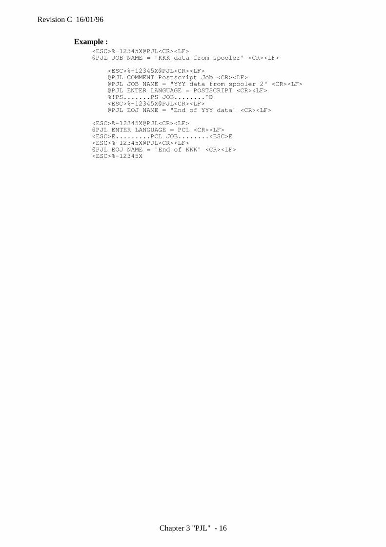
Revision C 16/01/96
Chapter 3 "PJL" - 16
Example :<ESC>%-12345X@PJL<CR><LF>@PJL JOB NAME = "KKK data from spooler" <CR><LF>
<ESC>%-12345X@PJL<CR><LF>@PJL COMMENT Postscript Job <CR><LF>@PJL JOB NAME = "YYY data from spooler 2" <CR><LF>@PJL ENTER LANGUAGE = POSTSCRIPT <CR><LF>%!PS.......PS JOB........^D<ESC>%-12345X@PJL<CR><LF>@PJL EOJ NAME = "End of YYY data" <CR><LF>
<ESC>%-12345X@PJL<CR><LF>@PJL ENTER LANGUAGE = PCL <CR><LF><ESC>E.........PCL JOB........<ESC>E<ESC>%-12345X@PJL<CR><LF>@PJL EOJ NAME = "End of KKK" <CR><LF><ESC>%-12345X
Revision C 16/01/96
Chapter 3 "PJL" - 17
6. ENVIRONMENT COMMANDS
6.1. IntroductionThe HL-10h, HL-1260 and HL-660 printers have many features which you are able to set using printercommands or through the printer control panel (remote printer console program). A combination ofPJL commands and printer emulation commands allows you to set printer features to the desired state.This chapter describes the setting of printer features known as printer environments, and PJLcommands you are able to use to set printer features to a desired state as follows;
• DEFAULTSet the default value for environment variables. (storing them in non volatile RAM , so called NV-RAM)
• INITIALIZEReset the current and default PJL variables to the factory default values
• RESETReset the current PJL values to the default values
• SETSet an environment variable to a specified value until the next PJL reset condition.
Print environmentThe printer constantly maintains four environments, which are listed below in priority order
1. Factory Default EnvironmentThese environment setting values are permanently stored in the printer. The printer uses these settingsvalues when it is powered on for the first time after shipping from the factory, and after the@PJL INITIALIZE command is performed.
2. User Default EnvironmentThese environment setting values are stored in the printer's NV-RAM through the printer's controlpanel (Remote Printer Console) or @PJL DEFAULT command. These values are placed into the PJLCurrent Environment following any PJL reset condition.
3. PJL Current EnvironmentThese environment setting values contain the current PJL feature settings. Current settings are based onthe User Default values and include any settings modified by the @PJL SET command. These settingvalues are changed to the User Default values as the default when a PJL reset occurs.
4. Modified Print EnvironmentThese environment settings become active just after a printer language is entered. At that time, the PJLCurrent environment values are loaded into the Modified Print Environment and act as a base set offeatures. Then, Printer language commands are used to change or modify feature settings to the desiredstate. Whenever an emulation is activated or a reset command is received (reset command includes anyprinter language reset or PJL reset), the PJL Current environment settings are loaded into the ModifiedPrint environment.
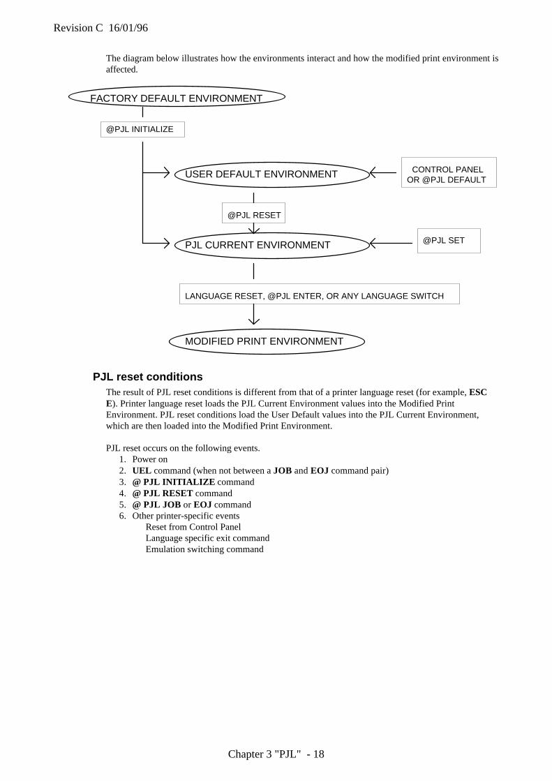
Revision C 16/01/96
Chapter 3 "PJL" - 18
The diagram below illustrates how the environments interact and how the modified print environment isaffected.
FACTORY DEFAULT ENVIRONMENT
USER DEFAULT ENVIRONMENT
PJL CURRENT ENVIRONMENT
MODIFIED PRINT ENVIRONMENT
@PJL INITIALIZE
@PJL RESET
LANGUAGE RESET, @PJL ENTER, OR ANY LANGUAGE SWITCH
CONTROL PANELOR @PJL DEFAULT
@PJL SET
PJL reset conditionsThe result of PJL reset conditions is different from that of a printer language reset (for example, ESCE). Printer language reset loads the PJL Current Environment values into the Modified PrintEnvironment. PJL reset conditions load the User Default values into the PJL Current Environment,which are then loaded into the Modified Print Environment.
PJL reset occurs on the following events.1. Power on2. UEL command (when not between a JOB and EOJ command pair)3. @ PJL INITIALIZE command4. @ PJL RESET command5. @ PJL JOB or EOJ command6. Other printer-specific events
Reset from Control PanelLanguage specific exit commandEmulation switching command
Revision C 16/01/96
Chapter 3 "PJL" - 19
Remember about environmentsRemember the following points when you use PJL to set the printer to a desired state.
1. The current feature settings are the same as the control panel values ( or values in the remote printerconsole program) when beginning a PJL job.
2. The current feature settings (Modified Print Environment) become the same as the PJL CurrentEnvironment when the printer enters a printer language. The feature settings are modified by theprinter language command once a printer language is started. All other settings are overridden byprinter language commands.
3. The SET command changes the PJL Current Environment settings. These settings are effective untilthe next PJL reset condition.
4. The Control Panel, the remote printer console program or the DEFAULT command changes theUser Default Environment (= Control Panel settings or remote printer console program settings)
5. Printer language commands change the Modified Print Environment. These settings are effectiveduring a printer language job. The PJL Current Environment settings are loaded into the ModifiedPrint Environment by a printer language specific reset, for example, ESC E for PCL.
6. Always use the PJL RESET command after a job is completed if the SET command is used in thePJL job.
PJL environment variablesThis section lists the PJL environment variables. There are two kinds of PJL environment variables,General PJL environment variables and Printer language -specific variables. For all variables except theread-only variables, value settings can be modified using @PJL SET, @PJL RESET, @PJLDEFAULT , and @PJL INITIALIZE .
Using the @ PJL INQUIRE and @ PJL DINQUIRE , you can request value settings for the printerfeatures. For the details of these commands, see the next section.
NOTE:1. Use PJL commands only when no printer language commands are available for a desired feature.2. When setting printer features with PJL, use the SET and RESET commands when you want to affect
the current PJL job only.If you want to affect more than the current job, use the DEFAULT and INITIALIZE commands.
3. Supported valuables varies according to your printer mode.
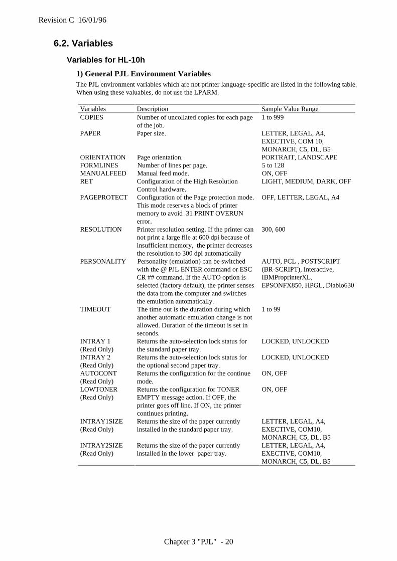
Revision C 16/01/96
Chapter 3 "PJL" - 20
6.2. Variables
Variables for HL-10h
1) General PJL Environment VariablesThe PJL environment variables which are not printer language-specific are listed in the following table.When using these valuables, do not use the LPARM.
Variables Description Sample Value RangeCOPIES Number of uncollated copies for each page
of the job.1 to 999
PAPER Paper size. LETTER, LEGAL, A4,EXECTIVE, COM 10,MONARCH, C5, DL, B5
ORIENTATION Page orientation. PORTRAIT, LANDSCAPEFORMLINES Number of lines per page. 5 to 128MANUALFEED Manual feed mode. ON, OFFRET Configuration of the High Resolution
Control hardware.LIGHT, MEDIUM, DARK, OFF
PAGEPROTECT Configuration of the Page protection mode.This mode reserves a block of printermemory to avoid 31 PRINT OVERUNerror.
OFF, LETTER, LEGAL, A4
RESOLUTION Printer resolution setting. If the printer cannot print a large file at 600 dpi because ofinsufficient memory, the printer decreasesthe resolution to 300 dpi automatically
300, 600
PERSONALITY Personality (emulation) can be switchedwith the @ PJL ENTER command or ESCCR ## command. If the AUTO option isselected (factory default), the printer sensesthe data from the computer and switchesthe emulation automatically.
AUTO, PCL , POSTSCRIPT(BR-SCRIPT), Interactive,IBMProprinterXL,EPSONFX850, HPGL, Diablo630
TIMEOUT The time out is the duration during whichanother automatic emulation change is notallowed. Duration of the timeout is set inseconds.
1 to 99
INTRAY 1(Read Only)
Returns the auto-selection lock status forthe standard paper tray.
LOCKED, UNLOCKED
INTRAY 2(Read Only)
Returns the auto-selection lock status forthe optional second paper tray.
LOCKED, UNLOCKED
AUTOCONT(Read Only)
Returns the configuration for the continuemode.
ON, OFF
LOWTONER(Read Only)
Returns the configuration for TONEREMPTY message action. If OFF, theprinter goes off line. If ON, the printercontinues printing.
ON, OFF
INTRAY1SIZE(Read Only)
Returns the size of the paper currentlyinstalled in the standard paper tray.
LETTER, LEGAL, A4,EXECTIVE, COM10,MONARCH, C5, DL, B5
INTRAY2SIZE(Read Only)
Returns the size of the paper currentlyinstalled in the lower paper tray.
LETTER, LEGAL, A4,EXECTIVE, COM10,MONARCH, C5, DL, B5
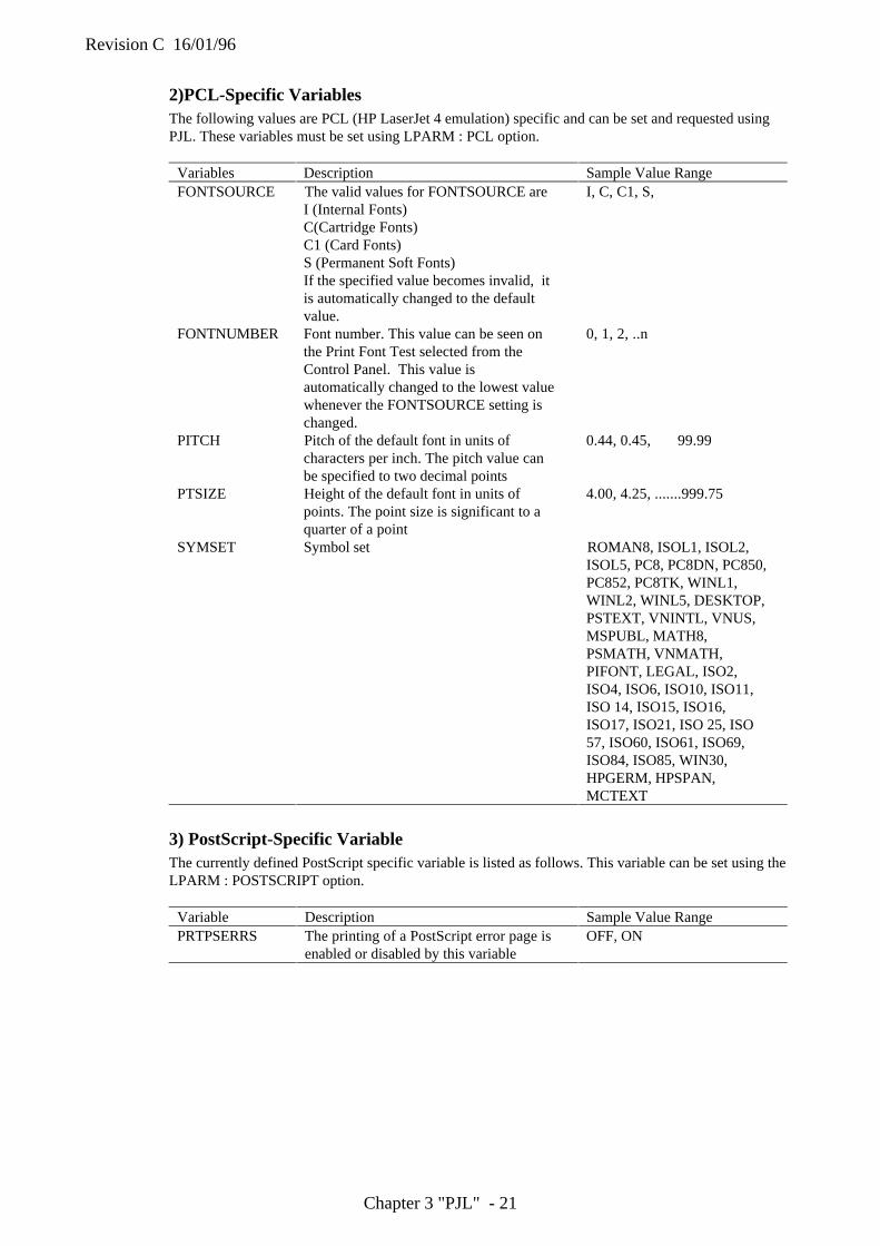
Revision C 16/01/96
Chapter 3 "PJL" - 21
2)PCL-Specific VariablesThe following values are PCL (HP LaserJet 4 emulation) specific and can be set and requested usingPJL. These variables must be set using LPARM : PCL option.
Variables Description Sample Value RangeFONTSOURCE The valid values for FONTSOURCE are
I (Internal Fonts)C(Cartridge Fonts)C1 (Card Fonts)S (Permanent Soft Fonts)If the specified value becomes invalid, itis automatically changed to the defaultvalue.
I, C, C1, S,
FONTNUMBER Font number. This value can be seen onthe Print Font Test selected from theControl Panel. This value isautomatically changed to the lowest valuewhenever the FONTSOURCE setting ischanged.
0, 1, 2, ..n
PITCH Pitch of the default font in units ofcharacters per inch. The pitch value canbe specified to two decimal points
0.44, 0.45, 99.99
PTSIZE Height of the default font in units ofpoints. The point size is significant to aquarter of a point
4.00, 4.25, .......999.75
SYMSET Symbol set ROMAN8, ISOL1, ISOL2,ISOL5, PC8, PC8DN, PC850,PC852, PC8TK, WINL1,WINL2, WINL5, DESKTOP,PSTEXT, VNINTL, VNUS,MSPUBL, MATH8,PSMATH, VNMATH,PIFONT, LEGAL, ISO2,ISO4, ISO6, ISO10, ISO11,ISO 14, ISO15, ISO16,ISO17, ISO21, ISO 25, ISO57, ISO60, ISO61, ISO69,ISO84, ISO85, WIN30,HPGERM, HPSPAN,MCTEXT
3) PostScript-Specific VariableThe currently defined PostScript specific variable is listed as follows. This variable can be set using theLPARM : POSTSCRIPT option.
Variable Description Sample Value RangePRTPSERRS The printing of a PostScript error page is
enabled or disabled by this variableOFF, ON
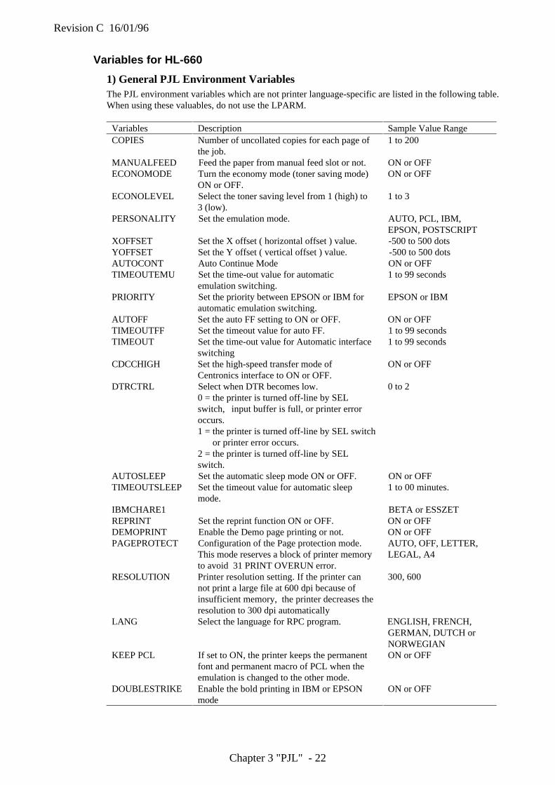
Revision C 16/01/96
Chapter 3 "PJL" - 22
Variables for HL-660
1) General PJL Environment VariablesThe PJL environment variables which are not printer language-specific are listed in the following table.When using these valuables, do not use the LPARM.
Variables Description Sample Value RangeCOPIES Number of uncollated copies for each page of
the job.1 to 200
MANUALFEED Feed the paper from manual feed slot or not. ON or OFFECONOMODE Turn the economy mode (toner saving mode)
ON or OFF.ON or OFF
ECONOLEVEL Select the toner saving level from 1 (high) to3 (low).
1 to 3
PERSONALITY Set the emulation mode. AUTO, PCL, IBM,EPSON, POSTSCRIPT
XOFFSET Set the X offset ( horizontal offset ) value. -500 to 500 dotsYOFFSET Set the Y offset ( vertical offset ) value. -500 to 500 dotsAUTOCONT Auto Continue Mode ON or OFFTIMEOUTEMU Set the time-out value for automatic
emulation switching.1 to 99 seconds
PRIORITY Set the priority between EPSON or IBM forautomatic emulation switching.
EPSON or IBM
AUTOFF Set the auto FF setting to ON or OFF. ON or OFFTIMEOUTFF Set the timeout value for auto FF. 1 to 99 secondsTIMEOUT Set the time-out value for Automatic interface
switching1 to 99 seconds
CDCCHIGH Set the high-speed transfer mode ofCentronics interface to ON or OFF.
ON or OFF
DTRCTRL Select when DTR becomes low.0 = the printer is turned off-line by SELswitch, input buffer is full, or printer erroroccurs.1 = the printer is turned off-line by SEL switch
or printer error occurs.2 = the printer is turned off-line by SELswitch.
0 to 2
AUTOSLEEP Set the automatic sleep mode ON or OFF. ON or OFFTIMEOUTSLEEP Set the timeout value for automatic sleep
mode.1 to 00 minutes.
IBMCHARE1 BETA or ESSZETREPRINT Set the reprint function ON or OFF. ON or OFFDEMOPRINT Enable the Demo page printing or not. ON or OFFPAGEPROTECT Configuration of the Page protection mode.
This mode reserves a block of printer memoryto avoid 31 PRINT OVERUN error.
AUTO, OFF, LETTER,LEGAL, A4
RESOLUTION Printer resolution setting. If the printer cannot print a large file at 600 dpi because ofinsufficient memory, the printer decreases theresolution to 300 dpi automatically
300, 600
LANG Select the language for RPC program. ENGLISH, FRENCH,GERMAN, DUTCH orNORWEGIAN
KEEP PCL If set to ON, the printer keeps the permanentfont and permanent macro of PCL when theemulation is changed to the other mode.
ON or OFF
DOUBLESTRIKE Enable the bold printing in IBM or EPSONmode
ON or OFF
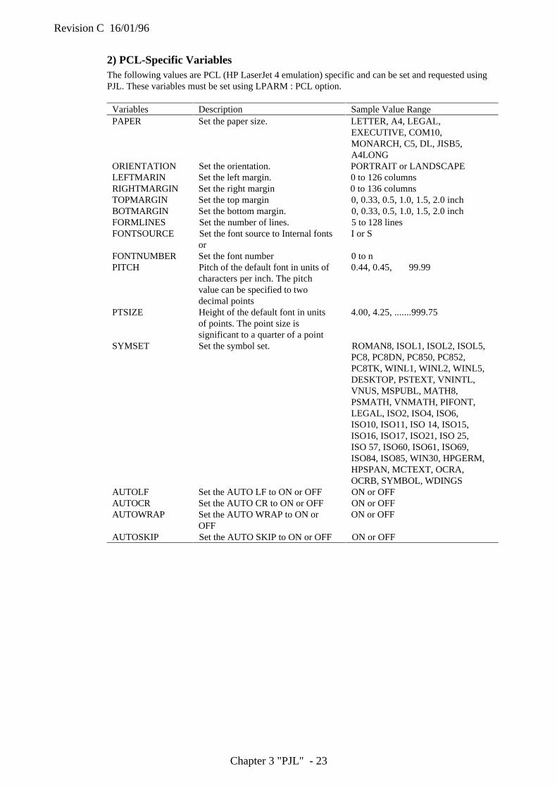
Revision C 16/01/96
Chapter 3 "PJL" - 23
2) PCL-Specific VariablesThe following values are PCL (HP LaserJet 4 emulation) specific and can be set and requested usingPJL. These variables must be set using LPARM : PCL option.
Variables Description Sample Value RangePAPER Set the paper size. LETTER, A4, LEGAL,
EXECUTIVE, COM10,MONARCH, C5, DL, JISB5,A4LONG
ORIENTATION Set the orientation. PORTRAIT or LANDSCAPELEFTMARIN Set the left margin. 0 to 126 columnsRIGHTMARGIN Set the right margin 0 to 136 columnsTOPMARGIN Set the top margin 0, 0.33, 0.5, 1.0, 1.5, 2.0 inchBOTMARGIN Set the bottom margin. 0, 0.33, 0.5, 1.0, 1.5, 2.0 inchFORMLINES Set the number of lines. 5 to 128 linesFONTSOURCE Set the font source to Internal fonts
orI or S
FONTNUMBER Set the font number 0 to nPITCH Pitch of the default font in units of
characters per inch. The pitchvalue can be specified to twodecimal points
0.44, 0.45, 99.99
PTSIZE Height of the default font in unitsof points. The point size issignificant to a quarter of a point
4.00, 4.25, .......999.75
SYMSET Set the symbol set. ROMAN8, ISOL1, ISOL2, ISOL5,PC8, PC8DN, PC850, PC852,PC8TK, WINL1, WINL2, WINL5,DESKTOP, PSTEXT, VNINTL,VNUS, MSPUBL, MATH8,PSMATH, VNMATH, PIFONT,LEGAL, ISO2, ISO4, ISO6,ISO10, ISO11, ISO 14, ISO15,ISO16, ISO17, ISO21, ISO 25,ISO 57, ISO60, ISO61, ISO69,ISO84, ISO85, WIN30, HPGERM,HPSPAN, MCTEXT, OCRA,OCRB, SYMBOL, WDINGS
AUTOLF Set the AUTO LF to ON or OFF ON or OFFAUTOCR Set the AUTO CR to ON or OFF ON or OFFAUTOWRAP Set the AUTO WRAP to ON or
OFFON or OFF
AUTOSKIP Set the AUTO SKIP to ON or OFF ON or OFF
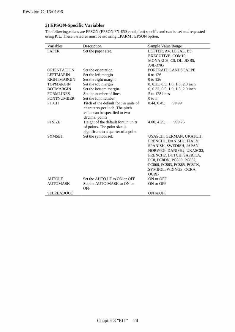
Revision C 16/01/96
Chapter 3 "PJL" - 24
3) EPSON-Specific VariablesThe following values are EPSON (EPSON FX-850 emulation) specific and can be set and requestedusing PJL. These variables must be set using LPARM : EPSON option.
Variables Description Sample Value RangePAPER Set the paper size. LETTER, A4, LEGAL, B5,
EXECUTIVE, COM10,MONARCH, C5, DL, JISB5,A4LONG
ORIENTATION Set the orientation. PORTRAIT, LANDSCALPELEFTMARIN Set the left margin 0 to 126RIGHTMARGIN Set the right margin 0 to 136TOPMARGIN Set the top margin 0, 0.33, 0.5, 1.0, 1.5, 2.0 inchBOTMARGIN Set the bottom margin. 0, 0.33, 0.5, 1.0, 1.5, 2.0 inchFORMLINES Set the number of lines. 5 to 128 linesFONTNUMBER Set the font number 0 to nPITCH Pitch of the default font in units of
characters per inch. The pitchvalue can be specified to twodecimal points
0.44, 0.45, 99.99
PTSIZE Height of the default font in unitsof points. The point size issignificant to a quarter of a point
4.00, 4.25, .......999.75
SYMSET Set the symbol set. USASCII, GERMAN, UKASCI1,FRENCH1, DANISH1, ITALY,SPANISH, SWEDISH, JAPAN,NORWEG, DANISH2, UKASCI2,FRENCH2, DUTCH, SAFRICA,PC8, PC8DN, PC850, PC852,PC860, PC863, PC865, PC8TK,SYMBOL, WDINGS, OCRA,OCRB
AUTOLF Set the AUTO LF to ON or OFF ON or OFFAUTOMASK Set the AUTO MASK to ON or
OFFON or OFF
SELREADOUT ON or OFF
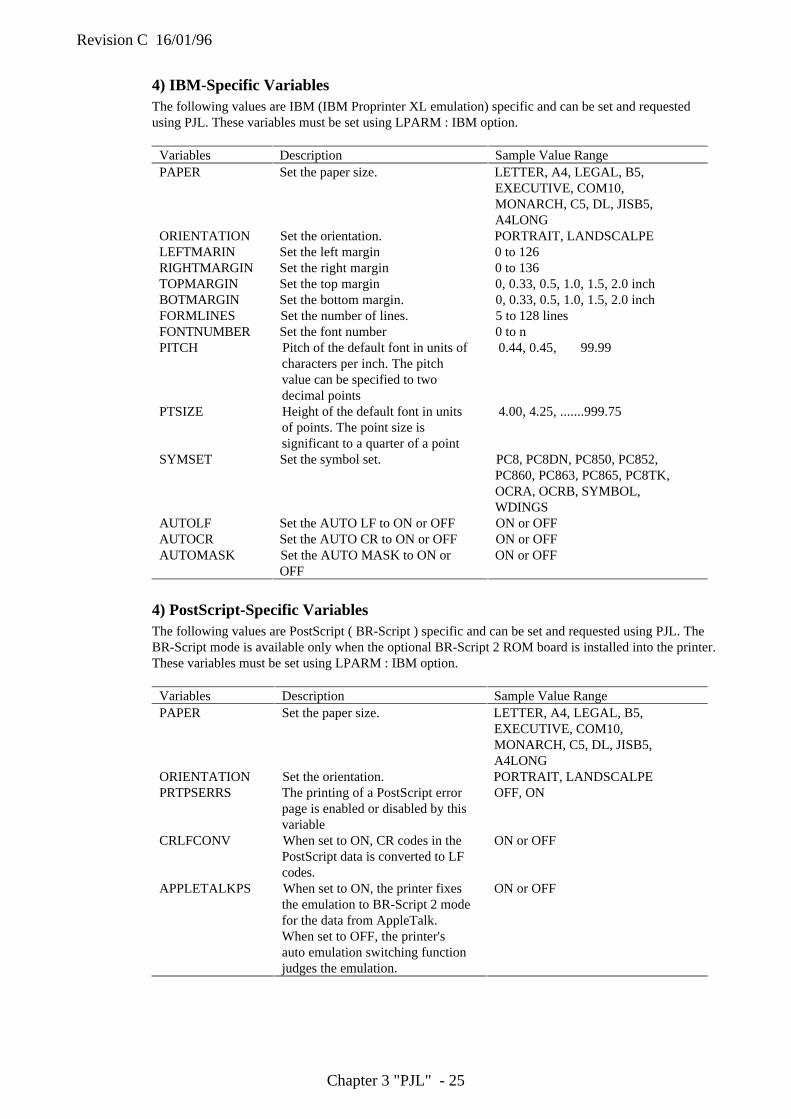
Revision C 16/01/96
Chapter 3 "PJL" - 25
4) IBM-Specific VariablesThe following values are IBM (IBM Proprinter XL emulation) specific and can be set and requestedusing PJL. These variables must be set using LPARM : IBM option.
Variables Description Sample Value RangePAPER Set the paper size. LETTER, A4, LEGAL, B5,
EXECUTIVE, COM10,MONARCH, C5, DL, JISB5,A4LONG
ORIENTATION Set the orientation. PORTRAIT, LANDSCALPELEFTMARIN Set the left margin 0 to 126RIGHTMARGIN Set the right margin 0 to 136TOPMARGIN Set the top margin 0, 0.33, 0.5, 1.0, 1.5, 2.0 inchBOTMARGIN Set the bottom margin. 0, 0.33, 0.5, 1.0, 1.5, 2.0 inchFORMLINES Set the number of lines. 5 to 128 linesFONTNUMBER Set the font number 0 to nPITCH Pitch of the default font in units of
characters per inch. The pitchvalue can be specified to twodecimal points
0.44, 0.45, 99.99
PTSIZE Height of the default font in unitsof points. The point size issignificant to a quarter of a point
4.00, 4.25, .......999.75
SYMSET Set the symbol set. PC8, PC8DN, PC850, PC852,PC860, PC863, PC865, PC8TK,OCRA, OCRB, SYMBOL,WDINGS
AUTOLF Set the AUTO LF to ON or OFF ON or OFFAUTOCR Set the AUTO CR to ON or OFF ON or OFFAUTOMASK Set the AUTO MASK to ON or
OFFON or OFF
4) PostScript-Specific VariablesThe following values are PostScript ( BR-Script ) specific and can be set and requested using PJL. TheBR-Script mode is available only when the optional BR-Script 2 ROM board is installed into the printer.These variables must be set using LPARM : IBM option.
Variables Description Sample Value RangePAPER Set the paper size. LETTER, A4, LEGAL, B5,
EXECUTIVE, COM10,MONARCH, C5, DL, JISB5,A4LONG
ORIENTATION Set the orientation. PORTRAIT, LANDSCALPEPRTPSERRS The printing of a PostScript error
page is enabled or disabled by thisvariable
OFF, ON
CRLFCONV When set to ON, CR codes in thePostScript data is converted to LFcodes.
ON or OFF
APPLETALKPS When set to ON, the printer fixesthe emulation to BR-Script 2 modefor the data from AppleTalk.When set to OFF, the printer'sauto emulation switching functionjudges the emulation.
ON or OFF
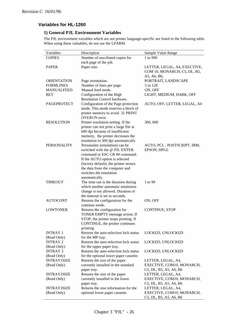
Revision C 16/01/96
Chapter 3 "PJL" - 26
Variables for HL-1260
1) General PJL Environment VariablesThe PJL environment variables which are not printer language-specific are listed in the following table.When using these valuables, do not use the LPARM.
Variables Description Sample Value RangeCOPIES Number of uncollated copies for
each page of the job.1 to 999
PAPER Paper size. LETTER, LEGAL, A4, EXECTIVE,COM 10, MONARCH, C5, DL, B5,A5, A6, B6,
ORIENTATION Page orientation. PORTRAIT, LANDSCAPEFORMLINES Number of lines per page. 5 to 128MANUALFEED Manual feed mode. ON, OFFRET Configuration of the High
Resolution Control hardware.LIGHT, MEDIUM, DARK, OFF
PAGEPROTECT Configuration of the Page protectionmode. This mode reserves a block ofprinter memory to avoid 31 PRINTOVERUN error.
AUTO, OFF, LETTER, LEGAL, A4
RESOLUTION Printer resolution setting. If theprinter can not print a large file at600 dpi because of insufficientmemory, the printer decreases theresolution to 300 dpi automatically
300, 600
PERSONALITY Personality (emulation) can beswitched with the @ PJL ENTERcommand or ESC CR ## command.If the AUTO option is selected(factory default), the printer sensesthe data from the computer andswitches the emulationautomatically.
AUTO, PCL , POSTSCRIPT, IBM,EPSON, HPGL
TIMEOUT The time out is the duration duringwhich another automatic emulationchange is not allowed. Duration ofthe timeout is set in seconds.
1 to 99
AUTOCONT Returns the configuration for thecontinue mode.
ON, OFF
LOWTONER Returns the configuration forTONER EMPTY message action. IfSTOP, the printer stops printing. IfCONTINUE, the printer continuesprinting.
CONTINUE, STOP
INTRAY 1(Read Only)
Returns the auto-selection lock statusfor the MP tray.
LOCKED, UNLOCKED
INTRAY 2(Read Only)
Returns the auto-selection lock statusfor the upper paper tray.
LOCKED, UNLOCKED
INTRAY 3(Read Only)
Returns the auto-selection lock statusfor the optional lower paper cassette.
LOCKED, UNLOCKED
INTRAY1SIZE(Read Only)
Returns the size of the papercurrently installed in the standardpaper tray.
LETTER, LEGAL, A4,EXECTIVE, COM10, MONARCH,C5, DL, B5, A5, A6, B6
INTRAY2SIZE(Read Only)
Returns the size of the papercurrently installed in the lowerpaper tray.
LETTER, LEGAL, A4,EXECTIVE, COM10, MONARCH,C5, DL, B5, A5, A6, B6
INTRAY3SIZE(Read Only)
Returns the size information for theoptional lower paper cassette.
LETTER, LEGAL, A4,EXECTIVE, COM10, MONARCH,C5, DL, B5, A5, A6, B6
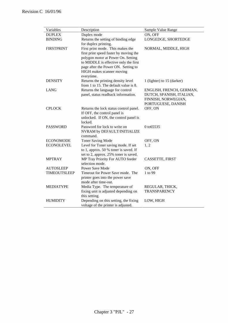
Revision C 16/01/96
Chapter 3 "PJL" - 27
Variables Description Sample Value RangeDUPLEX Duplex mode ON, OFFBINDING Returns the setting of binding edge
for duplex printing.LONGEDGE, SHORTEDGE
FIRSTPRINT First print mode. This makes thefirst print speed faster by moving thepolygon motor at Power On. Settingto MIDDLE is effective only the firstpage after the Power ON. Setting toHIGH makes scanner movingeverytime.
NORMAL, MIDDLE, HIGH
DENSITY Returns the printing density levelfrom 1 to 15. The default value is 8.
1 (lighter) to 15 (darker)
LANG Returns the language for controlpanel, status readback information.
ENGLISH, FRENCH, GERMAN,DUTCH, SPANISH, ITALIAN,FINNISH, NORWEGIAN,PORTUGUESE, DANISH
CPLOCK Returns the lock status control panel.If OFF, the control panel isunlocked. If ON, the control panel islocked.
OFF, ON
PASSWORD Password for lock to write onNVRAM by DEFAULT/INITIALIZEcommand.
0 to65535
ECONOMODE Toner Saving Mode OFF, ONECONOLEVEL Level for Toner saving mode. If set
to 1, approx. 50 % toner is saved. Ifset to 2, approx. 25% toner is saved.
1, 2
MPTRAY MP Tray Priority For AUTO feederselection mode.
CASSETTE, FIRST
AUTOSLEEP Power Save Mode ON, OFFTIMEOUTSLEEP Timeout for Power Save mode. The
printer goes into the power savemode after time-out.
1 to 99
MEDIATYPE Media Type. The temperature offixing unit is adjusted depending onthis setting.
REGULAR, THICK,TRANSPARENCY
HUMIDITY Depending on this setting, the fixingvoltage of the printer is adjusted.
LOW, HIGH
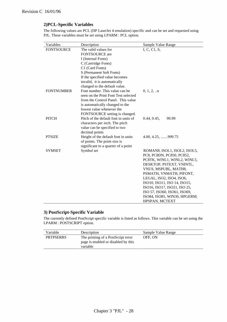
Revision C 16/01/96
Chapter 3 "PJL" - 28
2)PCL-Specific VariablesThe following values are PCL (HP LaserJet 4 emulation) specific and can be set and requested usingPJL. These variables must be set using LPARM : PCL option.
Variables Description Sample Value RangeFONTSOURCE The valid values for
FONTSOURCE areI (Internal Fonts)C (Cartridge Fonts)C1 (Card Fonts)S (Permanent Soft Fonts)If the specified value becomesinvalid, it is automaticallychanged to the default value.
I, C, C1, S,
FONTNUMBER Font number. This value can beseen on the Print Font Test selectedfrom the Control Panel. This valueis automatically changed to thelowest value whenever theFONTSOURCE setting is changed.
0, 1, 2, ..n
PITCH Pitch of the default font in units ofcharacters per inch. The pitchvalue can be specified to twodecimal points
0.44, 0.45, 99.99
PTSIZE Height of the default font in unitsof points. The point size issignificant to a quarter of a point
4.00, 4.25, .......999.75
SYMSET Symbol set ROMAN8, ISOL1, ISOL2, ISOL5,PC8, PC8DN, PC850, PC852,PC8TK, WINL1, WINL2, WINL5,DESKTOP, PSTEXT, VNINTL,VNUS, MSPUBL, MATH8,PSMATH, VNMATH, PIFONT,LEGAL, ISO2, ISO4, ISO6,ISO10, ISO11, ISO 14, ISO15,ISO16, ISO17, ISO21, ISO 25,ISO 57, ISO60, ISO61, ISO69,ISO84, ISO85, WIN30, HPGERM,HPSPAN, MCTEXT
3) PostScript-Specific VariableThe currently defined PostScript specific variable is listed as follows. This variable can be set using theLPARM : POSTSCRIPT option.
Variable Description Sample Value RangePRTPSERRS The printing of a PostScript error
page is enabled or disabled by thisvariable
OFF, ON
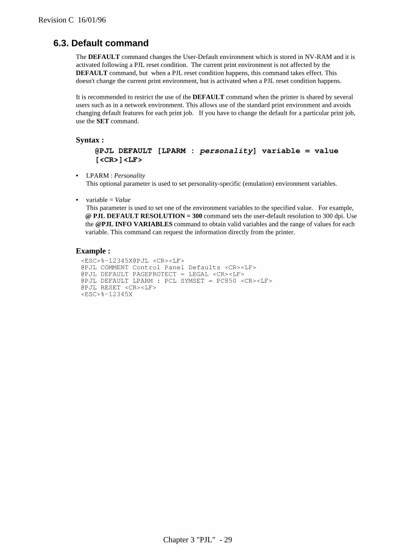
Revision C 16/01/96
Chapter 3 "PJL" - 29
6.3. Default commandThe DEFAULT command changes the User-Default environment which is stored in NV-RAM and it isactivated following a PJL reset condition. The current print environment is not affected by theDEFAULT command, but when a PJL reset condition happens, this command takes effect. Thisdoesn't change the current print environment, but is activated when a PJL reset condition happens.
It is recommended to restrict the use of the DEFAULT command when the printer is shared by severalusers such as in a network environment. This allows use of the standard print environment and avoidschanging default features for each print job. If you have to change the default for a particular print job,use the SET command.
Syntax :@PJL DEFAULT [LPARM : personality ] variable = value[<CR>]<LF>
• LPARM : PersonalityThis optional parameter is used to set personality-specific (emulation) environment variables.
• variable = ValueThis parameter is used to set one of the environment variables to the specified value. For example,@ PJL DEFAULT RESOLUTION = 300 command sets the user-default resolution to 300 dpi. Usethe @PJL INFO VARIABLES command to obtain valid variables and the range of values for eachvariable. This command can request the information directly from the printer.
Example :<ESC>%-12345X@PJL <CR><LF>@PJL COMMENT Control Panel Defaults <CR><LF>@PJL DEFAULT PAGEPROTECT = LEGAL <CR><LF>@PJL DEFAULT LPARM : PCL SYMSET = PC850 <CR><LF>@PJL RESET <CR><LF><ESC>%-12345X

Revision C 16/01/96
Chapter 3 "PJL" - 30
6.4. Initialize command
The INITIALIZE command resets the PJL Current Environment and User Default Environmentvariables to the Factory Default values. I/O configuration values and the unsolicited status settings arenot affected by this command.
It is recommended to restrict the use of the INITIALIZE command when the printer is shared by severalusers such as in a networking environment in order to use a standard environment and avoid havingdefault features changed by different print jobs.
Syntax :@PJL INITIALIZE [<CR>]<LF>
Parameters :• The INITIALIZE command has no parameters.
• The INITIALIZE command resets the following environment variables to the Factory Defaultvalues.
• If any additional personality (emulation) is added to the printer, the printer may support morepersonality-specific variables than the variables listed above. In any case, the INITIALIZEcommand resets the PJL Current and User Default environment values for all personalities to theirfactory default.
Example :<ESC>%-12345X@PJL <CR><LF>@PJL COMMENT setting to <CR><LF>@PJL COMMENT factory defaults <CR><LF>@PJL INITIALIZE <CR><LF><ESC>%-12345X
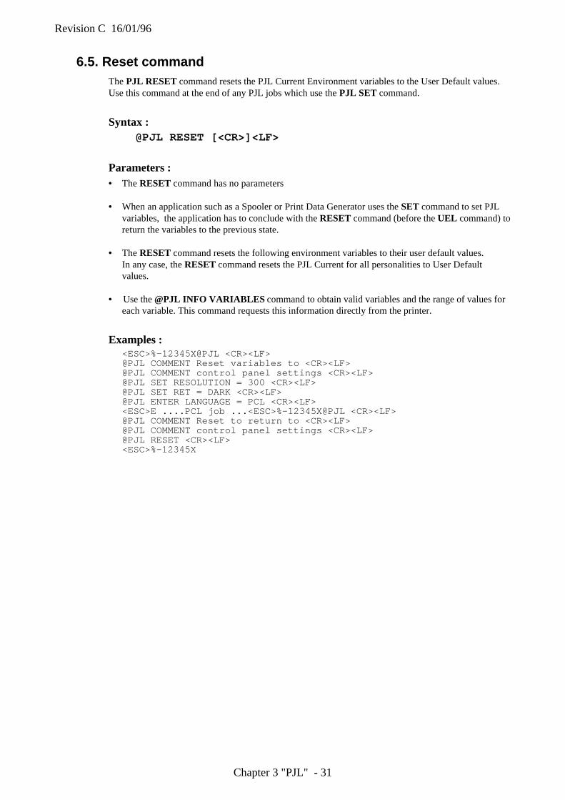
Revision C 16/01/96
Chapter 3 "PJL" - 31
6.5. Reset commandThe PJL RESET command resets the PJL Current Environment variables to the User Default values.Use this command at the end of any PJL jobs which use the PJL SET command.
Syntax :@PJL RESET [<CR>]<LF>
Parameters :• The RESET command has no parameters
• When an application such as a Spooler or Print Data Generator uses the SET command to set PJLvariables, the application has to conclude with the RESET command (before the UEL command) toreturn the variables to the previous state.
• The RESET command resets the following environment variables to their user default values.In any case, the RESET command resets the PJL Current for all personalities to User Defaultvalues.
• Use the @PJL INFO VARIABLES command to obtain valid variables and the range of values foreach variable. This command requests this information directly from the printer.
Examples :<ESC>%-12345X@PJL <CR><LF>@PJL COMMENT Reset variables to <CR><LF>@PJL COMMENT control panel settings <CR><LF>@PJL SET RESOLUTION = 300 <CR><LF>@PJL SET RET = DARK <CR><LF>@PJL ENTER LANGUAGE = PCL <CR><LF><ESC>E ....PCL job ...<ESC>%-12345X@PJL <CR><LF>@PJL COMMENT Reset to return to <CR><LF>@PJL COMMENT control panel settings <CR><LF>@PJL RESET <CR><LF><ESC>%-12345X

Revision C 16/01/96
Chapter 3 "PJL" - 32
6.6. Set commandThe SET command enables you to change the value of PJL Current Environment variables during a PJLjob, or until a PJL reset condition resets the default values.Use this command to make a job-specific environment.
Syntax:@PJL SET [LPARM : personality ] variable = value[<CR>]<LF>
• LPARM : PersonalityThis optional parameter is used to set personality(emulation) -specific environment variables.
• variable = valueThis parameter sets one of the environment variables to the specified value.
For example, @ PJL SET RESOLUTION = 300 command sets the current resolution to 300 dpi.For a list of variables and values, see the following table.
• Use the @PJL INFO VARIABLES to obtain valid variables and the range of values for eachvariable. This command can request this information directly from the printer.
Parameters:• The printer control panel setting values and the feature settings stored in NV-RAM are not affected
by the values modified with the SET command.
• The setting values selected with the SET command are valid until the next PJL reset conditionoccurs.
• If the SET command is used in a job, use the RESET command after the job to reset the printer toUser default settings.
Examples:<ESC>%-12345X@PJL <CR><LF>@PJL COMMENT Setting PCL job <CR><LF>@PJL COMMENT to desired state <CR><LF>@PJL SET RET = DARK <CR><LF>@PJL SET PAGEPROTECT = OFF <CR><LF>@PJL SET RESOLUTION = 600 <CR><LF>@PJL ENTER LANGUAGE = PCL <CR><LF><ESC> E....PCL job .... <ESC>E<ESC>%-12345X@PJL <CR><LF>@PJL RESET <CR><LF><ESC>%-12345X

Revision C 16/01/96
Chapter 3 "PJL" - 33
7. STATUS READBACK COMMANDS
7.1. IntroductionApplications can request, by sending a PJL command to the printer, information such as configurationand status of the printer. The printer can be programmed to send back this information when requested,and also can send back voluntarily unsolicited information of its status such as cover open, off-line state,toner empty, displayed prompt message on the LCD, and other necessary information.
PJL Status Readback will help you to program the application to appropriately set the printer settings.
In this chapter, you can learn how to use PJL Status Readback in programming an application. Thefollowing Status Readback Commands are described :
� INQUIRE ... requests the information of the specified PJL Default setting (PJL CurrentEnvironment) set by @PJL SET or @PJL RESET command
� DINQUIRE ... requests the information of the specified User Default setting (User DefaultEnvironment) set by @PJL DEFAULT or @PJL INITIALIZE command or control panel
� ECHO ... request the printer to send back to the host computer a comment for the purpose ofsynchronization with each other in order to start communication
� INFO ... requests a specified category of information from the printer� USTATUS ... gives the printer permission to send back unsolicited information.� USTATUSOFF ... turns off all unsolicited status information set by USTATUS
Job Recovery is also described in this chapter.
Synchronization with the printerThe printer sends the status responses to the same I/O port as it received the request from. Therefore, ina shared or network environment, if the I/O port was used by another user and the printer is stillprocessing the previous job, the printer may send a response of the status of the previous user's jobagainst the request from the current application. In order to make sure that an application can receivecorrect responses for its request, it must synchronize itself with the printer by sending the ECHOcommand so as to be assured that the printer is ready for communication to you.
Basic Format of Status Readback ResponsesThe printer sends its status information to the host computer in the following format :
� starts with the @PJL prefix� ends with a <FF> character� All the data is in a readable ASCII format.
Each line in the PJL status responses is in the following format :� starts with a specific keyword� ends with <CR><LF>
For example, the readback response against the @PJL DINQUIRE is :
@PJL DINQUIRE [LPARM : personality ] variable <CR><LF>value <CR><LF><FF>
The application must read all the data between the @PJL and <CR><LF> codes. If the application cannot understand the meaning of the lines, it must ignore them. Future printers may send currently unusedkeywords.
Refer to each command description to learn about the format of responses from the printer.
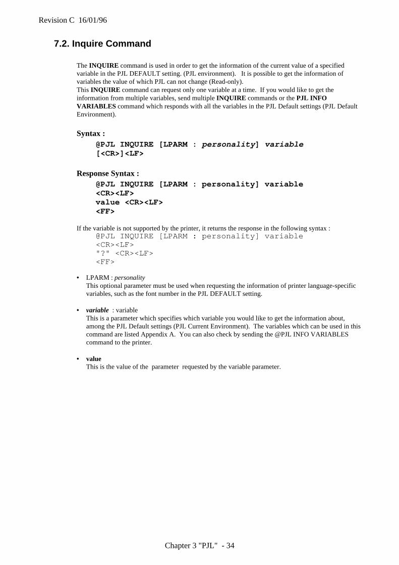
Revision C 16/01/96
Chapter 3 "PJL" - 34
7.2. Inquire Command
The INQUIRE command is used in order to get the information of the current value of a specifiedvariable in the PJL DEFAULT setting. (PJL environment). It is possible to get the information ofvariables the value of which PJL can not change (Read-only).This INQUIRE command can request only one variable at a time. If you would like to get theinformation from multiple variables, send multiple INQUIRE commands or the PJL INFOVARIABLES command which responds with all the variables in the PJL Default settings (PJL DefaultEnvironment).
Syntax :@PJL INQUIRE [LPARM : personality ] variable[<CR>]<LF>
Response Syntax :@PJL INQUIRE [LPARM : personality] variable<CR><LF>value <CR><LF><FF>
If the variable is not supported by the printer, it returns the response in the following syntax :@PJL INQUIRE [LPARM : personality] variable<CR><LF>"?" <CR><LF><FF>
• LPARM : personalityThis optional parameter must be used when requesting the information of printer language-specificvariables, such as the font number in the PJL DEFAULT setting.
• variable : variableThis is a parameter which specifies which variable you would like to get the information about,among the PJL Default settings (PJL Current Environment). The variables which can be used in thiscommand are listed Appendix A. You can also check by sending the @PJL INFO VARIABLEScommand to the printer.
• valueThis is the value of the parameter requested by the variable parameter.
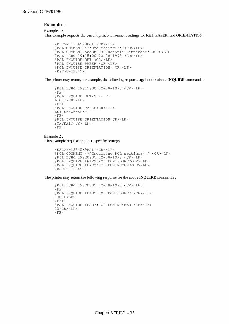
Revision C 16/01/96
Chapter 3 "PJL" - 35
Examples :Example 1 :This example requests the current print environment settings for RET, PAPER, and ORIENTATION :
<ESC>%-12345X@PJL <CR><LF>@PJL COMMENT ***Requesting*** <CR><LF>@PJL COMMENT about PJL Default Settings** <CR><LF>@PJL ECHO 19:15:00 02-20-1993 <CR><LF>@PJL INQUIRE RET <CR><LF>@PJL INQUIRE PAPER <CR><LF>@PJL INQUIRE ORIENTATION <CR><LF><ESC>%-12345X
The printer may return, for example, the following response against the above INQUIRE commands :
@PJL ECHO 19:15:00 02-20-1993 <CR><LF><FF>@PJL INQUIRE RET<CR><LF>LIGHT<CR><LF><FF>@PJL INQUIRE PAPER<CR><LF>LETTER<CR><LF><FF>@PJL INQUIRE ORIENTATION<CR><LF>PORTRAIT<CR><LF><FF>
Example 2 :This example requests the PCL-specific settings.
<ESC>%-12345X@PJL <CR><LF>@PJL COMMENT ***Inquiring PCL settings*** <CR><LF>@PJL ECHO 19:20:05 02-20-1993 <CR><LF>@PJL INQUIRE LPARM:PCL FONTSOURCE<CR><LF>@PJL INQUIRE LPARM:PCL FONTNUMBER<CR><LF><ESC>%-12345X
The printer may return the following response for the above INQUIRE commands :
@PJL ECHO 19:20:05 02-20-1993 <CR><LF><FF>@PJL INQUIRE LPARM:PCL FONTSOURCE <CR><LF>I<CR><LF><FF>@PJL INQUIRE LPARM:PCL FONTNUMBER <CR><LF>13<CR><LF><FF>

Revision C 16/01/96
Chapter 3 "PJL" - 36
7.3. DINQUIRE Command
The DINQUIRE command is used so as to get the information of the default value of a specific variablein the PJL Environment. (User Default Settings). It is also possible to get the value from variableswhich PJL can not change (Read-only).The returned value of User Default Settings is identical to the Control Panel Setting.This DINQUIRE command can request only one variable at a time. If you would like to getinformation from more variables, send multiple DINQUIRE commands.
Syntax :@PJL DINQUIRE [LPARM : personality ] variable[<CR>]<LF>
Response Syntax :@PJL DINQUIRE [LPARM : personality] variable<CR><LF>value <CR><LF><FF>
If the variable is not supported by the printer, it returns the response in the following syntax :@PJL DINQUIRE [LPARM : personality ] variable <CR><LF>"?" <CR><LF><FF>
• LPARM : personalityThis optional parameter must be used when requesting information about printer language-specificvariables such as the font number in the User Default setting.
• variableVariable is a parameter which specifies what you would like to get the information about, among theUser Default settings (User Default Environment). The valid variables are listed in the followingtables.
• valueValue is the returned value for the requested variable. See the tables following to learn about valuesfor specific variables.
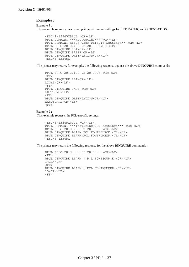
Revision C 16/01/96
Chapter 3 "PJL" - 37
Examples :Example 1 :This example requests the current print environment settings for RET, PAPER, and ORIENTATION :
<ESC>%-12345X@PJL <CR><LF>@PJL COMMENT ***Requesting*** <CR><LF>@PJL COMMENT about User Default Settings** <CR><LF>@PJL ECHO 20:30:00 02-20-1993<CR><LF>@PJL DINQUIRE RET<CR><LF>@PJL DINQUIRE PAPER<CR><LF>@PJL DINQUIRE ORIENTATION<CR><LF><ESC>%-12345X
The printer may return, for example, the following response against the above DINQUIRE commands:
@PJL ECHO 20:30:00 02-20-1993 <CR><LF><FF>@PJL DINQUIRE RET<CR><LF>LIGHT<CR><LF><FF>@PJL DINQUIRE PAPER<CR><LF>LETTER<CR>LF><FF>@PJL DINQUIRE ORIENTATION<CR><LF>LANDSCAPE<CR><LF><FF>
Example 2 :This example requests the PCL-specific settings.
<ESC>%-12345X@PJL <CR><LF>@PJL COMMENT ***Inquiring PCL settings*** <CR><LF>@PJL ECHO 20:33:05 02-20-1993 <CR><LF>@PJL DINQUIRE LPARM:PCL FONTSOURCE <CR><LF>@PJL DINQUIRE LPARM:PCL FONTNUMBER <CR><LF><ESC>%-12345X
The printer may return the following response for the above DINQUIRE commands :
@PJL ECHO 20:33:05 02-20-1993 <CR><LF><FF>@PJL DINQUIRE LPARM : PCL FONTSOURCE <CR><LF>I<CR><LF><FF>@PJL DINQUIRE LPARM : PCL FONTNUMBER <CR><LF>15<CR><LF><FF>
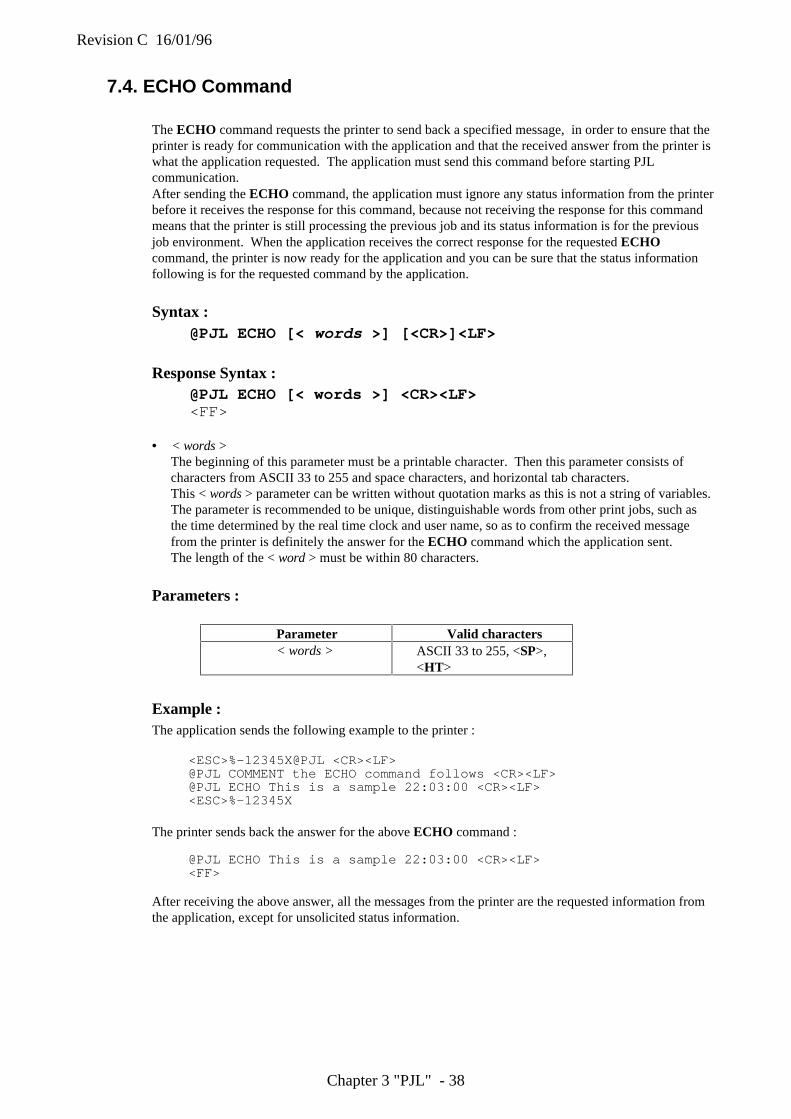
Revision C 16/01/96
Chapter 3 "PJL" - 38
7.4. ECHO Command
The ECHO command requests the printer to send back a specified message, in order to ensure that theprinter is ready for communication with the application and that the received answer from the printer iswhat the application requested. The application must send this command before starting PJLcommunication.After sending the ECHO command, the application must ignore any status information from the printerbefore it receives the response for this command, because not receiving the response for this commandmeans that the printer is still processing the previous job and its status information is for the previousjob environment. When the application receives the correct response for the requested ECHOcommand, the printer is now ready for the application and you can be sure that the status informationfollowing is for the requested command by the application.
Syntax :@PJL ECHO [< words >] [<CR>]<LF>
Response Syntax :@PJL ECHO [< words >] <CR><LF><FF>
• < words >The beginning of this parameter must be a printable character. Then this parameter consists ofcharacters from ASCII 33 to 255 and space characters, and horizontal tab characters.This < words > parameter can be written without quotation marks as this is not a string of variables.The parameter is recommended to be unique, distinguishable words from other print jobs, such asthe time determined by the real time clock and user name, so as to confirm the received messagefrom the printer is definitely the answer for the ECHO command which the application sent.The length of the < word > must be within 80 characters.
Parameters :
Parameter Valid characters< words > ASCII 33 to 255, <SP>,
<HT>
Example :The application sends the following example to the printer :
<ESC>%-12345X@PJL <CR><LF>@PJL COMMENT the ECHO command follows <CR><LF>@PJL ECHO This is a sample 22:03:00 <CR><LF><ESC>%-12345X
The printer sends back the answer for the above ECHO command :
@PJL ECHO This is a sample 22:03:00 <CR><LF><FF>
After receiving the above answer, all the messages from the printer are the requested information fromthe application, except for unsolicited status information.
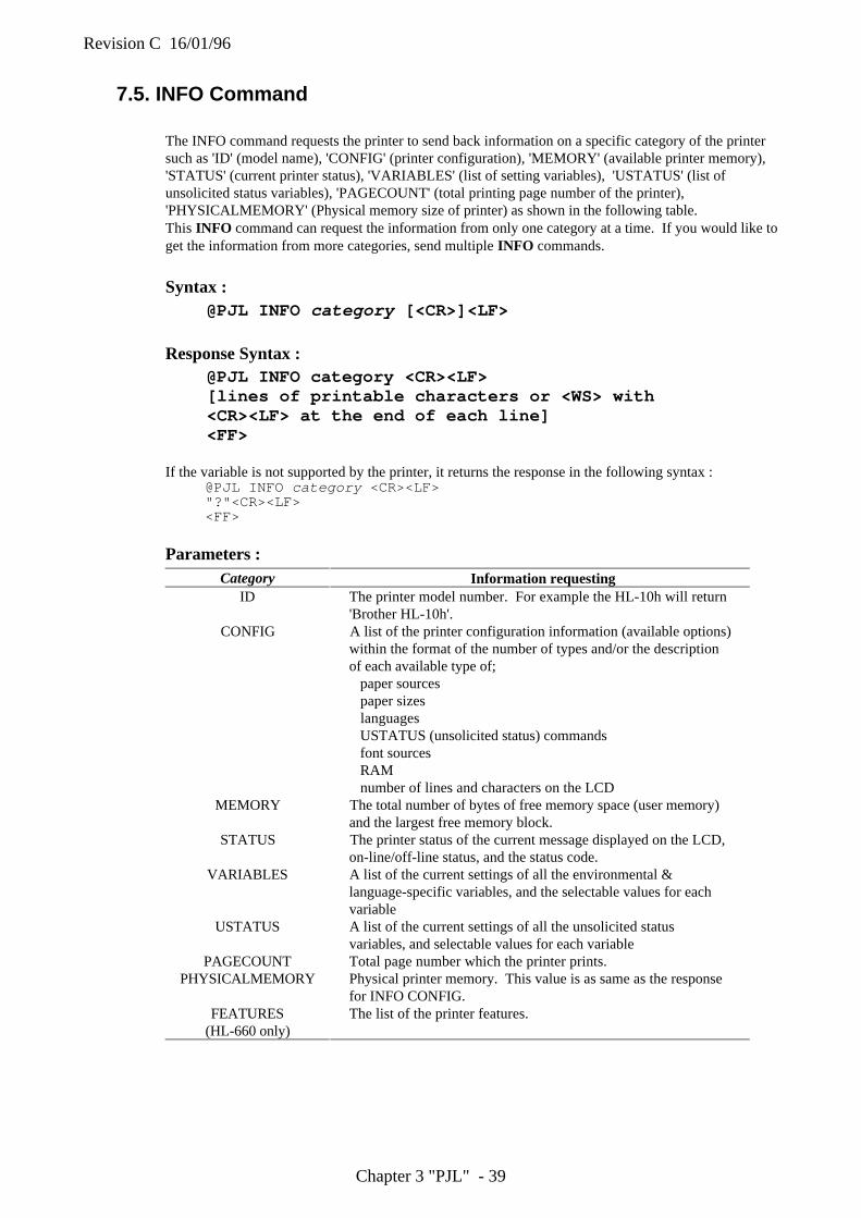
Revision C 16/01/96
Chapter 3 "PJL" - 39
7.5. INFO Command
The INFO command requests the printer to send back information on a specific category of the printersuch as 'ID' (model name), 'CONFIG' (printer configuration), 'MEMORY' (available printer memory),'STATUS' (current printer status), 'VARIABLES' (list of setting variables), 'USTATUS' (list ofunsolicited status variables), 'PAGECOUNT' (total printing page number of the printer),'PHYSICALMEMORY' (Physical memory size of printer) as shown in the following table.This INFO command can request the information from only one category at a time. If you would like toget the information from more categories, send multiple INFO commands.
Syntax :@PJL INFO category [<CR>]<LF>
Response Syntax :@PJL INFO category <CR><LF>[lines of printable characters or <WS> with<CR><LF> at the end of each line]<FF>
If the variable is not supported by the printer, it returns the response in the following syntax :@PJL INFO category <CR><LF>"?"<CR><LF><FF>
Parameters :Category Information requesting
ID The printer model number. For example the HL-10h will return'Brother HL-10h'.
CONFIG A list of the printer configuration information (available options)within the format of the number of types and/or the descriptionof each available type of; paper sources paper sizes languages USTATUS (unsolicited status) commands font sources RAM number of lines and characters on the LCD
MEMORY The total number of bytes of free memory space (user memory)and the largest free memory block.
STATUS The printer status of the current message displayed on the LCD,on-line/off-line status, and the status code.
VARIABLES A list of the current settings of all the environmental &language-specific variables, and the selectable values for eachvariable
USTATUS A list of the current settings of all the unsolicited statusvariables, and selectable values for each variable
PAGECOUNT Total page number which the printer prints.PHYSICALMEMORY Physical printer memory. This value is as same as the response
for INFO CONFIG.FEATURES
(HL-660 only)The list of the printer features.
Revision C 16/01/96
Chapter 3 "PJL" - 40
ID Category
The application can use @PJL INFO ID command to find out the printer model name. As the featuresof the printer may be changed by future revisions, the application should check them by using the@PJL INFO CONFIG command.
Example :The application sends the following command to the printer :
<ESC>%-12345X@PJL <CR><LF>@PJL INFO ID <CR><LF><ESC>%-12345X
The printer sends back the answer for the above INFO command if the printer name is HL-10h :
@PJL INFO ID<CR><LF>"Brother HL-10h"<CR><LF><FF>
CONFIG Category
The application can use @PJL INFO CONFIG command to have the printer return a list of printerconfiguration information. The list consists of the information on paper sources, paper sizes, languages,USTATUS (unsolicited status) commands, font sources, RAM size, number of lines and characters onthe LCD supported by the printer, with the format of the number of available types and/or thedescription of each type. The printer sends back a list of multiple information for one @PJL INFOCONFIG command.
Syntax :@PJL INFO CONFIG <CR><LF>
Response Syntax :@PJL INFO CONFIG <CR><LF>feature[=value][value feature information] <CR><LF>[<HT>returned option[ attribute] <CR><LF>]............feature[=value][value feature information] <CR><LF>[<HT>returned option[ attribute] <CR><LF>]<FF>
Revision C 16/01/96
Chapter 3 "PJL" - 41
Parameters :Parameter Range of Characters Descriptionfeature alphabetical letters
(ASCII 65-90 or 97-122), numbers (ASCII48-57)* Beginning with aletter
Name of an item of the printer configuration :for example )IN TRAYS (paper sources)OUT TRAYS (output trays)PAPER (paper sizes)LANGUAGES (printer languages)USTATUS (unsolicited status)FONT CARTRIDGE SLOTSMEMORY (RAM size)DISPLAY LINES (number of lines available on theLCD)DISPLAY CHARACTER SIZE (number ofcharacters available on the LCD)etc.
value numbers Value for the feature, or value which shows anumber or range of options to follow
featureinformation
alphabetical letters(ASCII 65-90 or 97-122), numbers (ASCII48-57)* separated from othersby spaces
Type of the following information:ENUMERATEDRANGEREADONLYetc.
returnedoption
alphabetical letters(ASCII 65-90 or 97-122), numbers (ASCII48-57)
An option of the item, such as PCL of the item ofLANGUAGES
attribute alphabetical letters(ASCII 65-90 or 97-122), numbers (ASCII48-57)
Further information for a returned option. Forexample, a PC attribute following an INTRAY2returned option indicates INTRAY2 means LC(optional tray2)
Example :The application sends the following command to the printer :
<ESC>%-12345X@PJL<CR><LF>@PJL INFO CONFIG<CR><LF><ESC>%-12345X
The printer may send back the answer for the above INFO command :
@PJL INFO CONFIG<CR><LF>IN TRAYS [1 ENUMERATED]<CR><LF>
INTRAY1 PC<CR><LF>INTRAY2 LC<CR><LF>
OUT TRAYS [2 ENUMERATED]<CR><LF>NORMAL FACEDOWN<CR><LF>
PAPER [9 ENUMERATED]<CR><LF>LETTER<CR><LF>LEGAL<CR><LF>A4<CR><LF>EXECUTIVE<CR><LF>MONARCH<CR><LF>COM10<CR><LF>DL<CR><LF>C5<CR><LF>B5<CR><LF>
Revision C 16/01/96
Chapter 3 "PJL" - 42
LANGUAGES [5 EMULATED]<CR><LF>PCL<CR><LF>POSTSCRIPT<CR><LF>IBM<CR><LF>EPSON<CR><LF>HPGL<CR><LF>
USTATUS [4 ENUMERATED]DEVICE<CR><LF>JOB<CR><LF>PAGE<CR><LF>TIMED<CR><LF>
FONT CARTRIDGE SLOTS [2 ENUMERATED]<CR><LF>CARTRIDGE<CR><LF>CARTRIDGE1<CR><LF>
MEMORY=2097152<CR><LF>DISPLAY LINES=1<CR><LF>DISPLAY CHARACTER SIZE=16<CR><LF><FF>
In this example, IN TRAYS [2 ENUMERATED] indicates that there are two options in IN TRAYS(paper sources), and MEMORY=2097152 indicates the RAM size in the printer is 2097152 bytes.
MEMORY Category
The application can use @PJL INFO MEMORY command to check the size of total free memory andthe largest free memory block in the printer.The free memory size may vary according to the personality (printer language). In order to know thefree memory size in PCL, use the <ESC>*s1M (Free Space command) in the PCL status readbackcommands.
Example :The application sends the following command to the printer :
<ESC>%-12345X@PJL<CR><LF>@PJL COMMENT the INFO MEMORY command follows<CR><LF>@PJL ECHO This is a sample 2-28-1993 19:03:00<CR><LF>@PJL INFO MEMORY<CR><LF><ESC>%-12345X
The printer sends back the answer for the above command :
@PJL ECHO This is a sample 2-28-1993 19:03:00<CR><LF><FF>@PJL INFO MEMORY<CR><LF>TOTAL=159984<CR><LF>LARGEST=53322<CR><LF><FF>
Revision C 16/01/96
Chapter 3 "PJL" - 43
STATUS Category
The application can use @PJL INFO STATUS command to check the printer on-line/off-line status,the current message on the LCD, and a status code. The ONLINE=TRUE indicates the printer isonline, while the ONLINE=FALSE shows it is off-line. Refer to the list of the PJL Status Codes in theAppendix for the meanings of the returned status codes.
Example :The application sends the following command to the printer :
<ESC>%-12345X@PJL<CR><LF>@PJL COMMENT the INFO STATUS command follows<CR><LF>@PJL ECHO This is a sample 2-28-1993 19:10:00<CR><LF>@PJL INFO STATUS<CR><LF><ESC>%-12345X
The printer sends back the answer for the above command when BR-Script mode and letter sized paperare selected and it is in idle status:
@PJL ECHO This is a sample 2-28-1993 19:10:00<CR><LF><FF>@PJL INFO STATUS<CR><LF>CODE=10001<CR><LF>DISPLAY="00 IDLE 001P LT"<CR><LF>ONLINE=TRUE<CR><LF><FF>
VARIABLES Category
The application can send the @PJL INFO VARIABLES command to get a list of possible variablesfor printer environment settings, possible language-specific variables, and the current settings for both,and the possible values or range for those variables. Refer to the "Environment Variables" in Chapter 6for more information about the variables for the environment settings.
The language-specific variables returned from the printer depend on the current environment and areindicated with LPARM: personality.
The value and options for the FONTSOURCE variable depend on the installed font sources such ascartridge, downloaded permanent soft fonts.
The range of fonts listed for FONTNUMBER variable is only for the current font source. The upperlimit value of the range varies according to the number of fonts in the current font source.
Example :The application sends the following command to the printer :
<ESC>%-12345X@PJL <CR><LF>@PJL COMMENT the INFO VARIABLES command <CR><LF>@PJL ECHO This is a sample 2-28-1993 19:35:00 <CR><LF>@PJL INFO VARIABLES <CR><LF><ESC>%-12345X
The printer may send back the answer for the above command :@PJL ECHO This is a sample 2-28-1993 19:35:00 <CR><LF><FF>@PJL INFO VARIABLES<CR><LF>COPIES=3 [2 RANGE]<CR><LF>
1<CR><LF>999<CR><LF>
PAPER=LETTER [9 ENUMERATED]<CR><LF>LETTER<CR><LF>LEGAL<CR><LF>
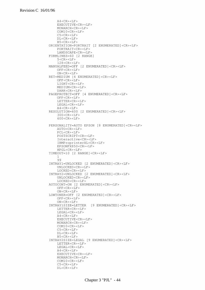
Revision C 16/01/96
Chapter 3 "PJL" - 44
A4<CR><LF>EXECUTIVE<CR><LF>MONARCH<CR><LF>COM10<CR><LF>C5<CR><LF>DL<CR><LF>B5<CR><LF>
ORIENTATION=PORTRAIT [2 ENUMERATED]<CR><LF>PORTRAIT<CR><LF>LANDSCAPE<CR><LF>
FORMLINES=60 [2 RANGE]5<CR><LF>128<CR><LF>
MANUALFEED=OFF [2 ENUMERATED]<CR><LF>OFF<CR><LF>ON<CR><LF>
RET=MEDIUM [4 ENUMERATED]<CR><LF>OFF<CR><LF>LIGHT<CR><LF>MEDIUM<CR><LF>DARK<CR><LF>
PAGEPROTECT=OFF [4 ENUMERATED]<CR><LF>OFF<CR><LF>LETTER<CR><LF>LEGAL<CR><LF>A4<CR><LF>
RESOLUTION=600 [2 ENUMERATED]<CR><LF>300<CR><LF>600<CR><LF>
PERSONALITY=AUTO EPSON [8 ENUMERATED]<CR><LF>AUTO<CR><LF>PCL<CR><LF>POSTSCRIPT<CR><LF>Interactive<CR><LF>IBMProprinterXL<CR><LF>EPSONFX850<CR><LF>HPGL<CR><LF>
TIMEOUT=10 [2 RANGE]<CR><LF>199
INTRAY1=UNLOCKED [2 ENUMERATED]<CR><LF>UNLOCKED<CR><LF>LOCKED<CR><LF>
INTRAY2=UNLOCKED [2 ENUMERATED]<CR><LF>UNLOCKED<CR><LF>LOCKED<CR><LF>
AUTOCONT=ON [2 ENUMERATED]<CR><LF>OFF<CR><LF>ON<CR><LF>
LOWTONER=OFF [2 ENUMERATED]<CR><LF>OFF<CR><LF>ON<CR><LF>
INTRAY1SIZE=LETTER [9 ENUMERATED]<CR><LF>LETTER<CR><LF>LEGAL<CR><LF>A4<CR><LF>EXECUTIVE<CR><LF>MONARCH<CR><LF>COM10<CR><LF>C5<CR><LF>DL<CR><LF>B5<CR><LF>
INTRAY2SIZE=LEGAL [9 ENUMERATED]<CR><LF>LETTER<CR><LF>LEGAL<CR><LF>A4<CR><LF>EXECUTIVE<CR><LF>MONARCH<CR><LF>COM10<CR><LF>C5<CR><LF>DL<CR><LF>
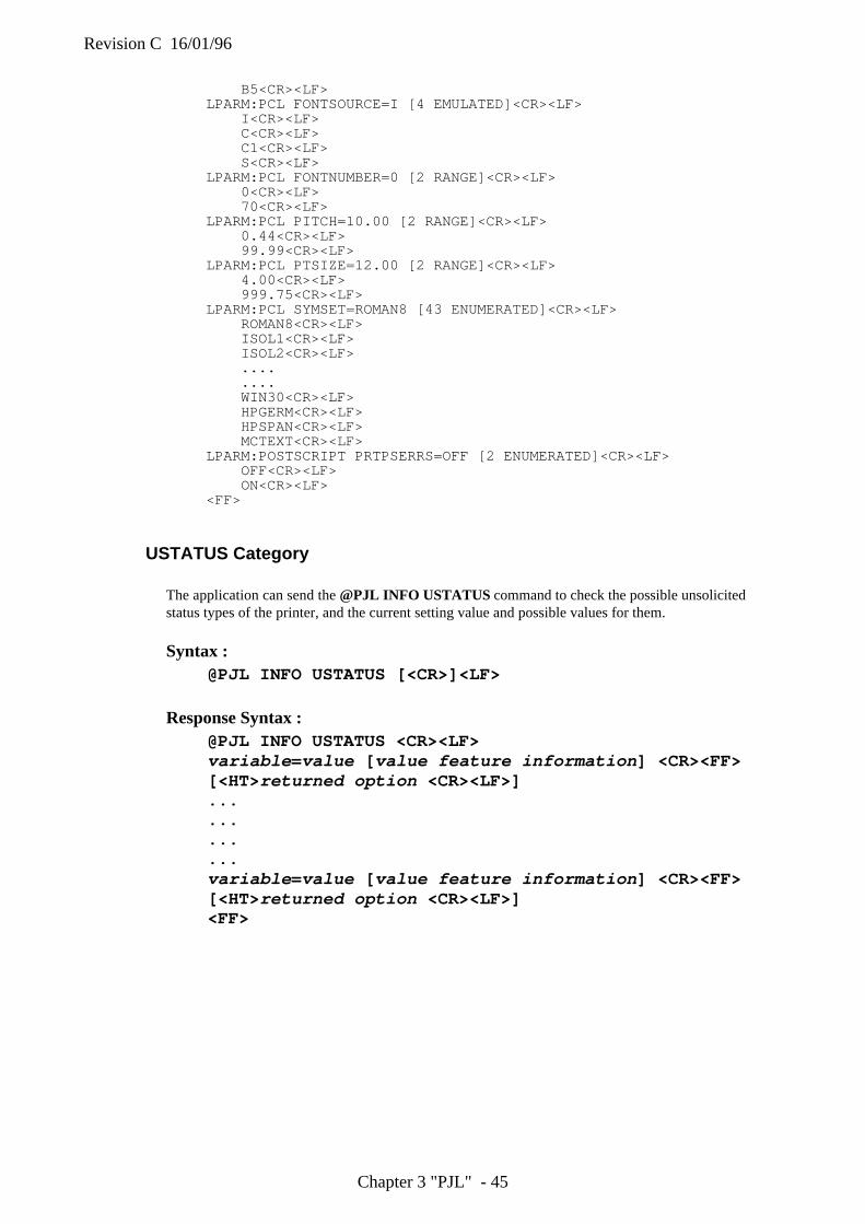
Revision C 16/01/96
Chapter 3 "PJL" - 45
B5<CR><LF>LPARM:PCL FONTSOURCE=I [4 EMULATED]<CR><LF>
I<CR><LF>C<CR><LF>C1<CR><LF>S<CR><LF>
LPARM:PCL FONTNUMBER=0 [2 RANGE]<CR><LF>0<CR><LF>70<CR><LF>
LPARM:PCL PITCH=10.00 [2 RANGE]<CR><LF>0.44<CR><LF>99.99<CR><LF>
LPARM:PCL PTSIZE=12.00 [2 RANGE]<CR><LF>4.00<CR><LF>999.75<CR><LF>
LPARM:PCL SYMSET=ROMAN8 [43 ENUMERATED]<CR><LF>ROMAN8<CR><LF>ISOL1<CR><LF>ISOL2<CR><LF>........WIN30<CR><LF>HPGERM<CR><LF>HPSPAN<CR><LF>MCTEXT<CR><LF>
LPARM:POSTSCRIPT PRTPSERRS=OFF [2 ENUMERATED]<CR><LF>OFF<CR><LF>ON<CR><LF>
<FF>
USTATUS Category
The application can send the @PJL INFO USTATUS command to check the possible unsolicitedstatus types of the printer, and the current setting value and possible values for them.
Syntax :@PJL INFO USTATUS [<CR>]<LF>
Response Syntax :@PJL INFO USTATUS <CR><LF>variable =value [ value feature information ] <CR><FF>[<HT> returned option <CR><LF>]............variable =value [ value feature information ] <CR><FF>[<HT> returned option <CR><LF>]<FF>
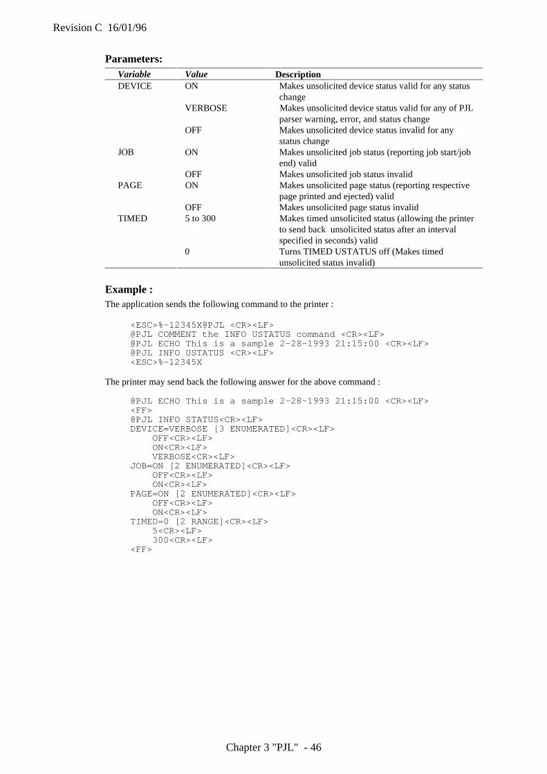
Revision C 16/01/96
Chapter 3 "PJL" - 46
Parameters:Variable Value DescriptionDEVICE ON Makes unsolicited device status valid for any status
changeVERBOSE Makes unsolicited device status valid for any of PJL
parser warning, error, and status changeOFF Makes unsolicited device status invalid for any
status changeJOB ON Makes unsolicited job status (reporting job start/job
end) validOFF Makes unsolicited job status invalid
PAGE ON Makes unsolicited page status (reporting respectivepage printed and ejected) valid
OFF Makes unsolicited page status invalidTIMED 5 to 300 Makes timed unsolicited status (allowing the printer
to send back unsolicited status after an intervalspecified in seconds) valid
0 Turns TIMED USTATUS off (Makes timedunsolicited status invalid)
Example :The application sends the following command to the printer :
<ESC>%-12345X@PJL <CR><LF>@PJL COMMENT the INFO USTATUS command <CR><LF>@PJL ECHO This is a sample 2-28-1993 21:15:00 <CR><LF>@PJL INFO USTATUS <CR><LF><ESC>%-12345X
The printer may send back the following answer for the above command :
@PJL ECHO This is a sample 2-28-1993 21:15:00 <CR><LF><FF>@PJL INFO STATUS<CR><LF>DEVICE=VERBOSE [3 ENUMERATED]<CR><LF>
OFF<CR><LF>ON<CR><LF>VERBOSE<CR><LF>
JOB=ON [2 ENUMERATED]<CR><LF>OFF<CR><LF>ON<CR><LF>
PAGE=ON [2 ENUMERATED]<CR><LF>OFF<CR><LF>ON<CR><LF>
TIMED=0 [2 RANGE]<CR><LF>5<CR><LF>300<CR><LF>
<FF>
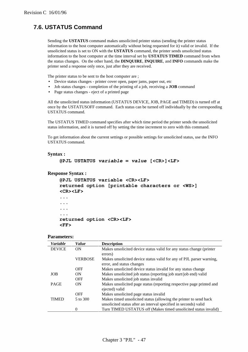
Revision C 16/01/96
Chapter 3 "PJL" - 47
7.6. USTATUS Command
Sending the USTATUS command makes unsolicited printer status (sending the printer statusinformation to the host computer automatically without being requested for it) valid or invalid. If theunsolicited status is set to ON with the USTATUS command, the printer sends unsolicited statusinformation to the host computer at the time interval set by USTATUS TIMED command from whenthe status changes. On the other hand, the DINQUIRE , INQUIRE , and INFO commands make theprinter send a response only once, just after they are received.
The printer status to be sent to the host computer are ;• Device status changes - printer cover open, paper jams, paper out, etc• Job status changes - completion of the printing of a job, receiving a JOB command• Page status changes - eject of a printed page
All the unsolicited status information (USTATUS DEVICE, JOB, PAGE and TIMED) is turned off atonce by the USTATUSOFF command. Each status can be turned off individually by the correspondingUSTATUS command.
The USTATUS TIMED command specifies after which time period the printer sends the unsolicitedstatus information, and it is turned off by setting the time increment to zero with this command.
To get information about the current settings or possible settings for unsolicited status, use the INFOUSTATUS command.
Syntax :@PJL USTATUS variable = value [<CR>]<LF>
Response Syntax :@PJL USTATUS variable <CR><LF>returned option [printable characters or <WS>]<CR><LF>............returned option <CR><LF><FF>
Parameters:Variable Value DescriptionDEVICE ON Makes unsolicited device status valid for any status change (printer
errors)VERBOSE Makes unsolicited device status valid for any of PJL parser warning,
error, and status changesOFF Makes unsolicited device status invalid for any status change
JOB ON Makes unsolicited job status (reporting job start/job end) validOFF Makes unsolicited job status invalid
PAGE ON Makes unsolicited page status (reporting respective page printed andejected) valid
OFF Makes unsolicited page status invalidTIMED 5 to 300 Makes timed unsolicited status (allowing the printer to send back
unsolicited status after an interval specified in seconds) valid0 Turn TIMED USTATUS off (Makes timed unsolicited status invalid)
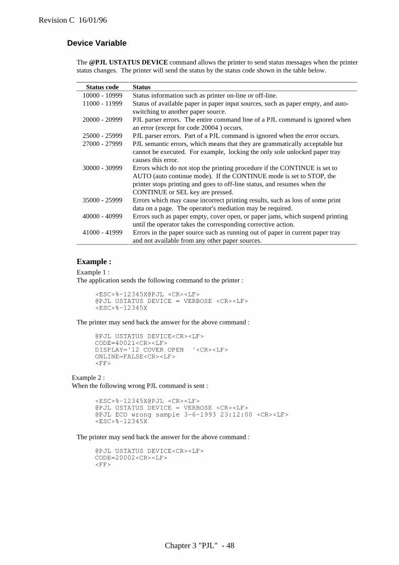
Revision C 16/01/96
Chapter 3 "PJL" - 48
Device Variable
The @PJL USTATUS DEVICE command allows the printer to send status messages when the printerstatus changes. The printer will send the status by the status code shown in the table below.
Status code Status10000 - 10999 Status information such as printer on-line or off-line.11000 - 11999 Status of available paper in paper input sources, such as paper empty, and auto-
switching to another paper source.20000 - 20999 PJL parser errors. The entire command line of a PJL command is ignored when
an error (except for code 20004 ) occurs.25000 - 25999 PJL parser errors. Part of a PJL command is ignored when the error occurs.27000 - 27999 PJL semantic errors, which means that they are grammatically acceptable but
cannot be executed. For example, locking the only sole unlocked paper traycauses this error.
30000 - 30999 Errors which do not stop the printing procedure if the CONTINUE is set toAUTO (auto continue mode). If the CONTINUE mode is set to STOP, theprinter stops printing and goes to off-line status, and resumes when theCONTINUE or SEL key are pressed.
35000 - 25999 Errors which may cause incorrect printing results, such as loss of some printdata on a page. The operator's mediation may be required.
40000 - 40999 Errors such as paper empty, cover open, or paper jams, which suspend printinguntil the operator takes the corresponding corrective action.
41000 - 41999 Errors in the paper source such as running out of paper in current paper trayand not available from any other paper sources.
Example :Example 1 :The application sends the following command to the printer :
<ESC>%-12345X@PJL <CR><LF>@PJL USTATUS DEVICE = VERBOSE <CR><LF><ESC>%-12345X
The printer may send back the answer for the above command :
@PJL USTATUS DEVICE<CR><LF>CODE=40021<CR><LF>DISPLAY='12 COVER OPEN '<CR><LF>ONLINE=FALSE<CR><LF><FF>
Example 2 :When the following wrong PJL command is sent :
<ESC>%-12345X@PJL <CR><LF>@PJL USTATUS DEVICE = VERBOSE <CR><LF>@PJL ECO wrong sample 3-6-1993 23:12:00 <CR><LF><ESC>%-12345X
The printer may send back the answer for the above command :
@PJL USTATUS DEVICE<CR><LF>CODE=20002<CR><LF><FF>
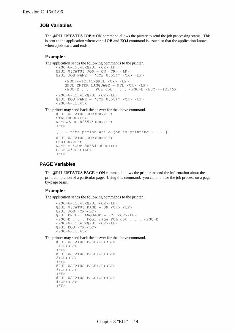
Revision C 16/01/96
Chapter 3 "PJL" - 49
JOB Variables
The @PJL USTATUS JOB = ON command allows the printer to send the job processing status. Thisis sent to the application whenever a JOB and EOJ command is issued so that the application knowswhen a job starts and ends.
Example :The application sends the following commands to the printer.
<ESC>%-12345X@PJL <CR><LF>@PJL USTATUS JOB = ON <CR> <LF>@PJL JOB NAME = "JOB 88554" <CR> <LF>
<ESC>%-12345X@PJL <CR> <LF>@PJL ENTER LANGUAGE = PCL <CR> <LF><ESC>E . . . PCL Job . . . <ESC>E <ESC>%-12345X
<ESC>%-12345X@PJL <CR><LF>@PJL EOJ NAME = "JOB 88554" <CR> <LF><ESC>%-12345X
The printer may send back the answer for the above command.@PJL USTATUS JOB<CR><LF>START<CR><LF>NAME="JOB 88554"<CR><LF><FF>
[ . . time period while job is printing . . . ]
@PJL USTATUS JOB<CR><LF>END<CR><LF>NAME = "JOB 88554"<CR><LF>PAGES=5<CR><LF><FF>
PAGE Variables
The @PJL USTATUS PAGE = ON command allows the printer to send the information about theprint completion of a particular page. Using this command, you can monitor the job process on a page-by-page basis.
Example :The application sends the following commands to the printer.
<ESC>%-12345X@PJL <CR><LF>@PJL USTATUS PAGE = ON <CR> <LF>@PJL JOB <CR><LF>@PJL ENTER LANGUAGE = PCL <CR><LF><ESC>E . . . Four-page PCL Job . . . <ESC>E<ESC>%-12345X@PJL <CR><LF>@PJL EOJ <CR><LF><ESC>%-12345X
The printer may send back the answer for the above command.@PJL USTATUS PAGE<CR><LF>1<CR><LF><FF>@PJL USTATUS PAGE<CR><LF>2<CR><LF><FF>@PJL USTATUS PAGE<CR><LF>3<CR><LF><FF>@PJL USTATUS PAGE<CR><LF>4<CR><LF><FF>
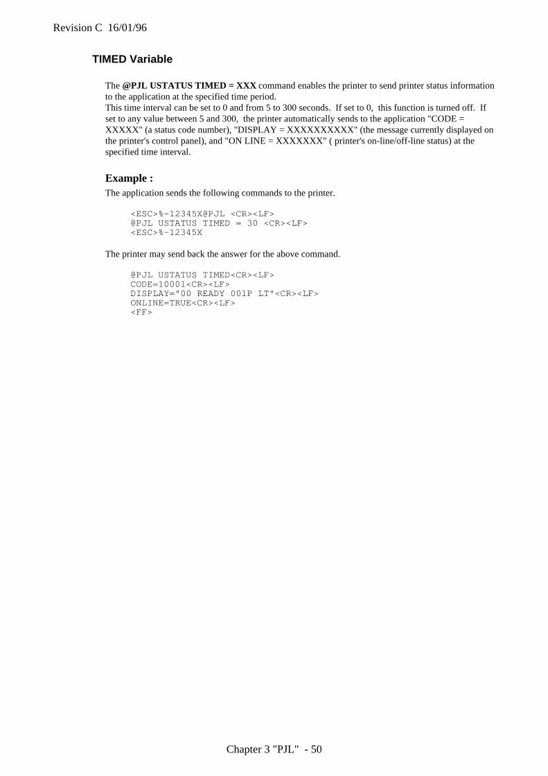
Revision C 16/01/96
Chapter 3 "PJL" - 50
TIMED Variable
The @PJL USTATUS TIMED = XXX command enables the printer to send printer status informationto the application at the specified time period.This time interval can be set to 0 and from 5 to 300 seconds. If set to 0, this function is turned off. Ifset to any value between 5 and 300, the printer automatically sends to the application "CODE =XXXXX" (a status code number), "DISPLAY = XXXXXXXXXX" (the message currently displayed onthe printer's control panel), and "ON LINE = XXXXXXX" ( printer's on-line/off-line status) at thespecified time interval.
Example :The application sends the following commands to the printer.
<ESC>%-12345X@PJL <CR><LF>@PJL USTATUS TIMED = 30 <CR><LF><ESC>%-12345X
The printer may send back the answer for the above command.
@PJL USTATUS TIMED<CR><LF>CODE=10001<CR><LF>DISPLAY="00 READY 001P LT"<CR><LF>ONLINE=TRUE<CR><LF><FF>
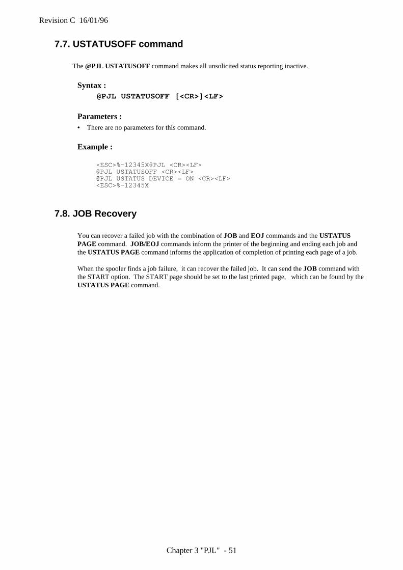
Revision C 16/01/96
Chapter 3 "PJL" - 51
7.7. USTATUSOFF command
The @PJL USTATUSOFF command makes all unsolicited status reporting inactive.
Syntax :@PJL USTATUSOFF [<CR>]<LF>
Parameters :• There are no parameters for this command.
Example :
<ESC>%-12345X@PJL <CR><LF>@PJL USTATUSOFF <CR><LF>@PJL USTATUS DEVICE = ON <CR><LF><ESC>%-12345X
7.8. JOB Recovery
You can recover a failed job with the combination of JOB and EOJ commands and the USTATUSPAGE command. JOB/EOJ commands inform the printer of the beginning and ending each job andthe USTATUS PAGE command informs the application of completion of printing each page of a job.
When the spooler finds a job failure, it can recover the failed job. It can send the JOB command withthe START option. The START page should be set to the last printed page, which can be found by theUSTATUS PAGE command.

Revision C 16/01/96
Chapter 3 "PJL" - 52
8. DEVICE ATTENDANCE COMMANDS
8.1. IntroductionYou can change display messages on the printer control panel by using PJL. The Operator can bealerted by this feature to what specific actions should be taken. This chapter shows you three deviceattendance commands.
RDYMSGBy using this command, you can change the message "00 READY" on the printer control panel intowhatever message you like. This command does not change the printer's online/offline state.
OPMSGBy using this command, the printer can display a message you specify on the printer switch panel LCDand set the printer to off-line ( non-ready state for printing ).
STMSGBy using this command, the printer can display a message you specify on the printer control panel LCDand the printer will go off-line. After the operator puts the printer back on-line by the on-line / off-linekey, the printer name is returned by the printer to the application.

Revision C 16/01/96
Chapter 3 "PJL" - 53
8.2. RDYMSG CommandWith the RDYMSG command, you can change the message "00 READY" on the printer control panelinto a specified message. The printer will be kept online.
Syntax :@PJL RDYMSG DISPLAY = " message " [<CR>]<LF>
Parameters : Parameter Functional Range Default DISPLAY = "message" ASCII 33 and ASCII
35 through 255, <SP>,<HT>
N/A
• DISPLAY = "message"
• You can use any combination of characters available on the printer except for the quotation marks(ASCII 34) within 16 characters. Also you can use spaces or horizontal tab. Characters must beenclosed in double quotes.
Comments :• This RDYMSG command keeps the printer online. You can display whatever message you like, for
example, job name, person name etc..
• @PJL RDYMSG DISPLAY = ""This command returns the display to "00 READY".
Example :The following example shows how to display the name of person who is printing the job.
<ESC>%-12345X@PJL <CR><LF>@PJL JOB NAME = "Tom's job" <CR><LF>@PJL RDYMSG DISPLAY = "TOM'S JOB" <CR><LF>
The following is an example of how to restore the display to the normal ready message.
<ESC>%-12345X@PJL <CR><LF>@PJL COMMENT Normal READY message <CR><LF>@PJL RDYMSG DISPLAY = "" <CR><LF>@PJL EOJ NAME = "End of Tom's Job" <CR><LF><ESC>%-12345X
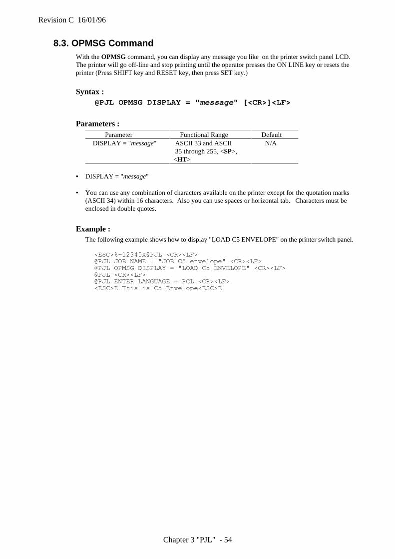
Revision C 16/01/96
Chapter 3 "PJL" - 54
8.3. OPMSG CommandWith the OPMSG command, you can display any message you like on the printer switch panel LCD.The printer will go off-line and stop printing until the operator presses the ON LINE key or resets theprinter (Press SHIFT key and RESET key, then press SET key.)
Syntax :@PJL OPMSG DISPLAY = " message " [<CR>]<LF>
Parameters : Parameter Functional Range Default DISPLAY = "message" ASCII 33 and ASCII
35 through 255, <SP>,<HT>
N/A
• DISPLAY = "message"
• You can use any combination of characters available on the printer except for the quotation marks(ASCII 34) within 16 characters. Also you can use spaces or horizontal tab. Characters must beenclosed in double quotes.
Example :The following example shows how to display "LOAD C5 ENVELOPE" on the printer switch panel.
<ESC>%-12345X@PJL <CR><LF>@PJL JOB NAME = "JOB C5 envelope" <CR><LF>@PJL OPMSG DISPLAY = "LOAD C5 ENVELOPE" <CR><LF>@PJL <CR><LF>@PJL ENTER LANGUAGE = PCL <CR><LF><ESC>E This is C5 Envelope<ESC>E
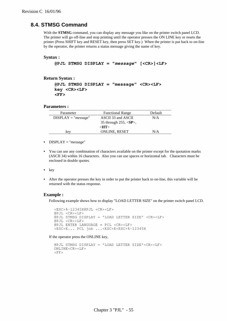
Revision C 16/01/96
Chapter 3 "PJL" - 55
8.4. STMSG CommandWith the STMSG command, you can display any message you like on the printer switch panel LCD.The printer will go off-line and stop printing until the operator presses the ON LINE key or resets theprinter (Press SHIFT key and RESET key, then press SET key.) When the printer is put back to on-lineby the operator, the printer returns a status message giving the name of key.
Syntax :@PJL STMSG DISPLAY = " message " [<CR>]<LF>
Return Syntax :@PJL STMSG DISPLAY = "message" <CR><LF>key <CR><LF><FF>
Parameters : Parameter Functional Range Default DISPLAY = "message" ASCII 33 and ASCII
35 through 255, <SP>,<HT>
N/A
key ONLINE, RESET N/A
• DISPLAY = "message"
• You can use any combination of characters available on the printer except for the quotation marks(ASCII 34) within 16 characters. Also you can use spaces or horizontal tab. Characters must beenclosed in double quotes.
• key
• After the operator presses the key in order to put the printer back to on-line, this variable will bereturned with the status response.
Example :Following example shows how to display "LOAD LETTER SIZE" on the printer switch panel LCD.
<ESC>%-12345X@PJL <CR><LF>@PJL <CR><LF>@PJL STMSG DISPLAY = "LOAD LETTER SIZE" <CR><LF>@PJL <CR><LF>@PJL ENTER LANGUAGE = PCL <CR><LF><ESC>E... PCL job ...<ESC>E<ESC>%-12345X
If the operator press the ONLINE key,
@PJL STMSG DISPLAY = "LOAD LETTER SIZE"<CR><LF>ONLINE<CR><LF><FF>
Revision C 16/01/96
Chapter 3 "PJL" - 56
INDEX
B
Basic Format of Status Readback Responses, 33
C
COMMENT command, 12conditions, 8CONFIG Category for INFO command, 41Context Switching, 13
D
Default command, 29DEMOPAGE, 11Device Attendance Commands, 53Device Variable for USTATUS command, 49DINQUIRE Command, 37
E
ECHO Command, 39emulation switching, 11End of Job, 15ENTER command, 11Environment Commands, 17EOJ Command, 15EPSON-Specific Variables, 24EXECUTE command, 11Explicit Switching, 13
F
Format of PJL, 6
I
IBM-Specific Variables, 25ID Category for INFO command, 41Implicit Switching, 13INFO Command, 40information line, 12Initialize command, 30Inquire Command, 35Invalid Commands, 7
J
JOB Command, 14job name, 14JOB Variables for USTATUS command, 50
K
Kernel Commands, 10
M
MEMORY Category for INFO command, 43
O
OPMSG Command, 55
P
PAGE Variables for USTATUS command, 50PCL-Specific Variables, 23PERMFONT, 11Print environment, 17PRTCONFIG, 11
R
RDYMSG Command, 54Reset command, 31reset conditions, 18Reset Printer (PJL), Error! Not a valid bookmark in entry
on page 25RESIFONT, 11
S
Set command, 32SHUTDOWN, 11start of job, 14STATUS Category for INFO command, 44Status Readback Commands, 33STMSG Command, 56Syntax of PJL, 6
T
TIMED Variable for USTATUS command, 51
U
UEL Command, 10Universal Exit Command, 10USTATUS Category for INFO command, 46USTATUS Command, 48USTATUSOFF command, 52
V
Variables, 7VARIABLES Category for INFO command, 44Variables for HL-10h, 20Variables for HL-1260, 26Variables for HL-660, 22
Revision C 16/01/96
Chapter 4 "Diablo 630" - 1
Chapter 4Diablo 630
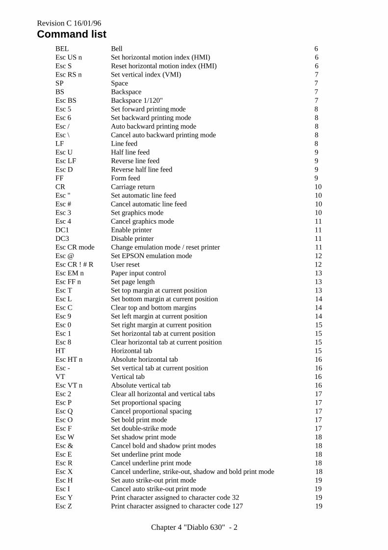
Revision C 16/01/96
Chapter 4 "Diablo 630" - 2
Command listBEL Bell 6Esc US n Set horizontal motion index (HMI) 6Esc S Reset horizontal motion index (HMI) 6Esc RS n Set vertical index (VMI) 7SP Space 7BS Backspace 7Esc BS Backspace 1/120" 7Esc 5 Set forward printing mode 8Esc 6 Set backward printing mode 8Esc / Auto backward printing mode 8Esc \ Cancel auto backward printing mode 8LF Line feed 8Esc U Half line feed 9Esc LF Reverse line feed 9Esc D Reverse half line feed 9FF Form feed 9CR Carriage return 10Esc " Set automatic line feed 10Esc # Cancel automatic line feed 10Esc 3 Set graphics mode 10Esc 4 Cancel graphics mode 11DC1 Enable printer 11DC3 Disable printer 11Esc CR mode Change emulation mode / reset printer 11Esc @ Set EPSON emulation mode 12Esc CR ! # R User reset 12Esc EM n Paper input control 13Esc FF n Set page length 13Esc T Set top margin at current position 13Esc L Set bottom margin at current position 14Esc C Clear top and bottom margins 14Esc 9 Set left margin at current position 14Esc 0 Set right margin at current position 15Esc 1 Set horizontal tab at current position 15Esc 8 Clear horizontal tab at current position 15HT Horizontal tab 15Esc HT n Absolute horizontal tab 16Esc - Set vertical tab at current position 16VT Vertical tab 16Esc VT n Absolute vertical tab 16Esc 2 Clear all horizontal and vertical tabs 17Esc P Set proportional spacing 17Esc Q Cancel proportional spacing 17Esc O Set bold print mode 17Esc F Set double-strike mode 17Esc W Set shadow print mode 18Esc & Cancel bold and shadow print modes 18Esc E Set underline print mode 18Esc R Cancel underline print mode 18Esc X Cancel underline, strike-out, shadow and bold print mode 18Esc H Set auto strike-out print mode 19Esc I Cancel auto strike-out print mode 19Esc Y Print character assigned to character code 32 19Esc Z Print character assigned to character code 127 19

Revision C 16/01/96
Chapter 4 "Diablo 630" - 3
1. IntroductionIn this emulation mode you can drive the printer directly by incorporating control codes and escapesequences in your program, or alternatively, applications software (for example, your word-processingsoftware) may send the necessary commands to the printer automatically. Check the manual that camewith your software package for instructions on how to configure your software to run in Diablo 630mode.
2. Emulation detailsThe following points should be borne in mind when running the printer in Diablo 630 mode.
2.1. Ignored commands
A few Diablo 630 commands have reduced effect, or no effect at all. These commands are as follows: theBEL control code (ASCII 7) which is used to sound the printer bell, is ignored. The DC1 control code(ASCII 17), used to disable the printer, is also ignored, as is the Esc \ escape sequence, normally used tocancel Auto Backward Printing Mode.
2.2 resolution
The resolution of the HL-10h printer is 600 dots per inch. When a line spacing or graphic cannot beimplemented exactly at 600 dots per inch the printer prints the closest possible approximation to thespecified image using 600 dots per inch.

Revision C 16/01/96
Chapter 4 "Diablo 630" - 4
3. Terminology
3.1. Syntax
The following conventions are used in this description of the Diablo 630 mode software commands:
A letter, control code, word or number in upright bold text is a literal character and should be sent to theprinter as the character code.
A letter or word in italics is a variable and you must substitute the appropriate value or values whenusing the command.
A statement element enclosed in angle brackets < > may be of any size up to some specified maximum.
3.2. Conventions
Although this machine is a laser printer and does not physically have a print head, for the purposes ofthis emulation description we refer to the location on the page at which the printer is currentlypositioned to print as the print position.
The printable area is the area of the page where the printer can place a dot.
The units of horizontal and vertical movement on the page are the horizontal motion index (HMI) andvertical motion index (VMI). You can set these units as you wish and then move the print positionhorizontally or vertically in multiples of them.
The bits that comprise a byte of data are numbered 1 to 8. Bit 1 is the least significant bit (LSB) and bit8 is the most significant bit (MSB).
The lower case ‘L’ character is shown as an ‘ ’ in the Esc printer command, to distinguish it from
the character ‘1’ (one).
4. Controlling the printerCommands are invoked using either control codes or escape sequences. You can send them to the printeras part of a program, using the same command that you would use to print a string on the printer. Forexample in BASIC you would use the LPRINT command.
The printer control panel can also be used to set margins and page size. Ensure that the control panelsettings and computer generated settings do not conflict with one another, or you may not get the resultsyou require.
4.1. The control panel
Refer to the Users guide for a description of how to use the printer control panel switches. You should beaware, however, that the following can be set using the control panel: automatic line feed (a line feed isperformed with every carriage return), auto mask (two-line top and bottom margins are automaticallyused on every page), paper size, top, bottom, left and right margins, the number of text lines per page,orientation (portrait or landscape), the current font, character set and emulation mode. Conflict betweencontrol panel settings and the settings you establish with software commands (or from applicationssoftware) is by far the most likely cause of unexpected printing results. Use this manual in conjunctionwith the Users guide to resolve these conflicts.
Revision C 16/01/96
Chapter 4 "Diablo 630" - 5
4.2. Control codes
Control codes are ASCII codes that instruct the printer to perform a particular operation, such as a linefeed. Send a control code to the printer by sending the same type of instruction you would use to print acharacter using its ASCII code number. For example, the ASCII code for a form feed is 12, so to get theprinter to perform a form feed use the following BASIC statement:
LPRINT CHR$(12);
The CHR$ operator is normally used to convert an ASCII code into its corresponding character.
4.3. escape sequences
Escape sequences tell the printer the Diablo 630 mode function to perform. An escape sequence consistsof the ESC character followed by one or more characters which define the operation to be performed.Send an escape sequence to the printer by sending the same type of instruction you would use to printcharacters using their ASCII codes. Some escape sequences require parameter values or data followingthem, for example, commands which turn a particular feature on and off. Numerical parameter data, too,is sent to the printer as if it were a character code to be printed. For example, to move the print positionto the third column position on the page the required escape sequence is Esc HT 3. In BASIC this wouldbe:
LPRINT CHR$(27); CHR$(9); CHR$(3);
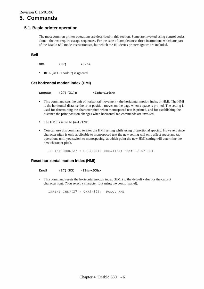
Revision C 16/01/96
Chapter 4 "Diablo 630" - 6
5. Commands
5.1. Basic printer operation
The most common printer operations are described in this section. Some are invoked using control codesalone - the rest require escape sequences. For the sake of completeness three instructions which are partof the Diablo 630 mode instruction set, but which the HL Series printers ignore are included.
Bell
BEL (07) <07h>
� BEL (ASCII code 7) is ignored.
Set horizontal motion index (HMI)
EscUSn (27)(31)n <1Bh><1Fh>n
� This command sets the unit of horizontal movement - the horizontal motion index or HMI. The HMIis the horizontal distance the print position moves on the page when a space is printed. The setting isused for determining the character pitch when monospaced text is printed, and for establishing thedistance the print position changes when horizontal tab commands are invoked.
� The HMI is set to be (n–1)/120".
� You can use this command to alter the HMI setting while using proportional spacing. However, sincecharacter pitch is only applicable to monospaced text the new setting will only affect space and taboperations until you switch to monospacing, at which point the new HMI setting will determine thenew character pitch.
LPRINT CHR$(27); CHR$(31); CHR$(13); 'Set 1/10" HMI
Reset horizontal motion index (HMI)
EscS (27)(83) <1Bh><53h>
� This command resets the horizontal motion index (HMI) to the default value for the currentcharacter font. (You select a character font using the control panel).
LPRINT CHR$(27); CHR$(83); 'Reset HMI
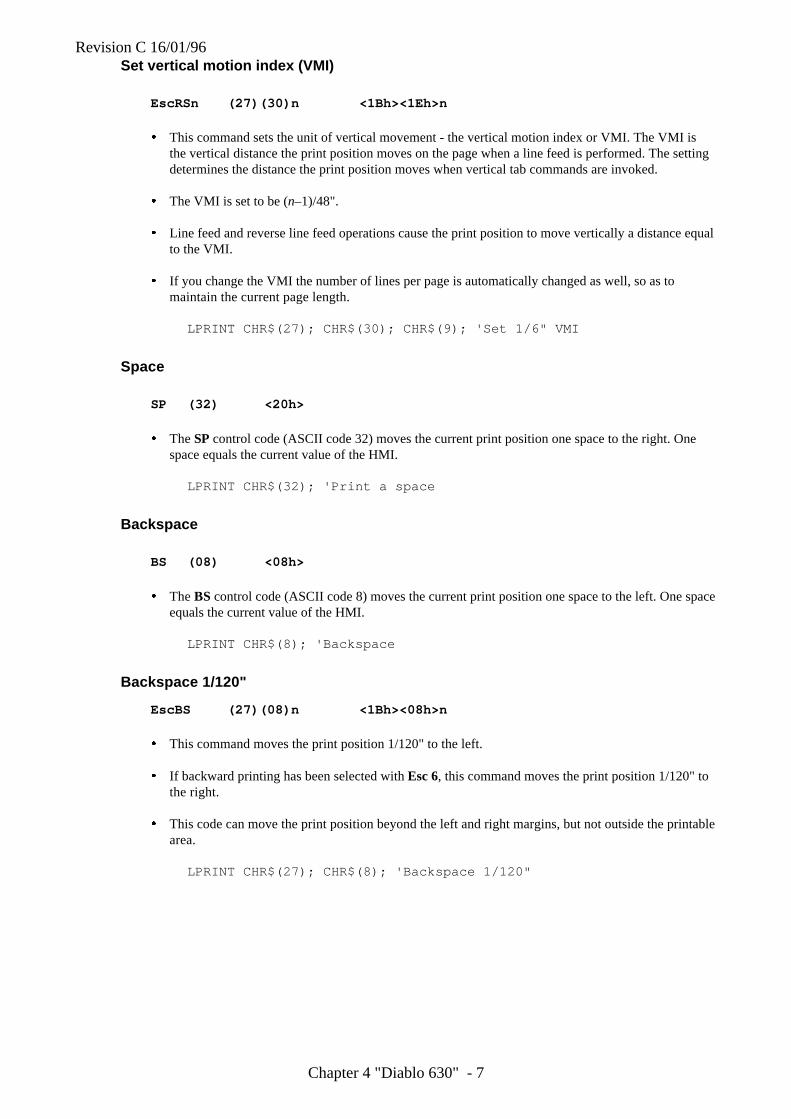
Revision C 16/01/96
Chapter 4 "Diablo 630" - 7
Set vertical motion index (VMI)
EscRSn (27)(30)n <1Bh><1Eh>n
� This command sets the unit of vertical movement - the vertical motion index or VMI. The VMI isthe vertical distance the print position moves on the page when a line feed is performed. The settingdetermines the distance the print position moves when vertical tab commands are invoked.
� The VMI is set to be (n–1)/48".
� Line feed and reverse line feed operations cause the print position to move vertically a distance equalto the VMI.
� If you change the VMI the number of lines per page is automatically changed as well, so as tomaintain the current page length.
LPRINT CHR$(27); CHR$(30); CHR$(9); 'Set 1/6" VMI
Space
SP (32) <20h>
� The SP control code (ASCII code 32) moves the current print position one space to the right. Onespace equals the current value of the HMI.
LPRINT CHR$(32); 'Print a space
Backspace
BS (08) <08h>
� The BS control code (ASCII code 8) moves the current print position one space to the left. One spaceequals the current value of the HMI.
LPRINT CHR$(8); 'Backspace
Backspace 1/120"
EscBS (27)(08)n <1Bh><08h>n
� This command moves the print position 1/120" to the left.
� If backward printing has been selected with Esc 6, this command moves the print position 1/120" tothe right.
� This code can move the print position beyond the left and right margins, but not outside the printablearea.
LPRINT CHR$(27); CHR$(8); 'Backspace 1/120"
Revision C 16/01/96
Chapter 4 "Diablo 630" - 8
Set forward printing mode
Esc5 (27)(53) <1Bh><35h>
� This command enables the printer to print text to the right of the right margin.
� Text cannot be printed outside the printable area.
� The Set Backward Printing Mode command, Esc 6, the Auto Backward Printing Mode command,Esc /, and the carriage return control code, CR, all cancel forward printing.
LPRINT CHR$(27); CHR$(53); 'Forward printing
Set backward printing mode
Esc6 (27)(54) <1Bh><36h>
� This command causes the printer to print text from right to left and also enables the printer to printtext to the left of the left margin.
� Text cannot be printed outside the printable area.
� The Set Forward Printing Mode command, Esc 5, the Auto Backward Printing Mode command, Esc/, and the carriage return control code, CR, all cancel backward printing.
LPRINT CHR$(27); CHR$(54); 'Backward printing
Auto backward printing mode
Esc/ (27)(47) <1Bh><2Fh>
� This command cancels forward printing mode or backward printing mode. Subsequent text is printedwithin the left and right margins.
LPRINT CHR$(27); CHR$(47); 'Normal printing mode
Cancel auto backward printing mode
Esc\ (27)(92) <1Bh><5Ch>
� The printer ignores this command.
Line feed
LF (10) <0Ah>
� The LF control code (ASCII code 10) moves the current print position down the page by a distanceequal to the current VMI.
� This code does not cause a carriage return to be performed.
� A line feed that would move the print position below the bottom margin moves it to the top of thenext page instead and performs a page eject.
LPRINT CHR$(10); 'Line feed
Revision C 16/01/96
Chapter 4 "Diablo 630" - 9
Half line feed
EscU (27)(85) <1Bh><55h>
� This command moves the current print position down the page by a distance equal to half the currentVMI.
� If the print position is such that this operation would move it beyond the bottom margin, the printposition is moved to the top of the next page instead.
LPRINT CHR$(27); CHR$(85); 'Half line feed
Reverse line feed
EscLF (27)(10) <1Bh><0Ah>
� This command moves the current print position up the page by a distance equal to the current VMI.
� This command can move the print position above the top margin.
LPRINT CHR$(27); CHR$(10); 'Reverse line feed
Reverse half line feed
EscD (27)(68) <1Bh><44h>
� This command moves the current print position up the page by a distance equal to half the currentVMI.
� This command can move the print position above the top margin.
LPRINT CHR$(27); CHR$(68); 'Reverse half line feed
Form feed
FF (12) <0Ch>
� The FF control code (ASCII code 12) ejects the current page and moves the current print position tothe top of the next page.
� If the current page is blank this control code has no effect.
� This code does not cause a carriage return to be performed, hence the print position does not changehorizontally.
LPRINT CHR$(12); 'Form feed
Revision C 16/01/96
Chapter 4 "Diablo 630" - 10
Carriage return
CR (13) <0Dh>
� The CR control code (ASCII 13) moves the print position to the left margin on the current line.
� If automatic line feed is on, this code moves the current print position to the left margin on the nextline. You can turn on automatic line feed either using the Esc " command or with the control panelswitches.
� The CR code cancels the following modes: shadow printing, bold printing, double-strike printing,forward printing and backward printing.
LPRINT CHR$(13); 'Carriage return
Set automatic line feed
Esc" (27)(34) <1Bh><22h>
� This command turns on the automatic line feed facility. Every time the printer executes a carriagereturn it executes a line feed as well.
� Invoking this code overrides any previous “auto LF” control panel setting you have made.
LPRINT CHR$(27); CHR$(34); 'Auto line feed on
Cancel automatic line feed
Esc# (27)(35) <1Bh><23h>
� This command turns off the automatic line feed facility that you set with the Esc " command.
LPRINT CHR$(27); CHR$(35); 'Auto line feed off
Set graphics mode
Esc3 (27)(51) <1Bh><33h>
� In graphics mode the print position does not change when a character is printed, hence consecutivecharacters printed in this mode will be placed one on top of another.
� In this mode the line feed and reverse line feed commands will move the print position down or upby 1/48", and the space and backspace codes will move the print position right or left by 1/60",irrespective of the current VMI and HMI settings.
� Both the Esc 4 command and the carriage return control code, CR, cancel graphics mode.
LPRINT CHR$(27); CHR$(51); 'Turn graphics mode on
Revision C 16/01/96
Chapter 4 "Diablo 630" - 11
Cancel graphics mode
Esc4 (27)(52) <1Bh><34h>
� This command turns off graphics mode.
LPRINT CHR$(27); CHR$(52); 'Turn graphics mode off
Enable printer
DC1 (17) <11h>
� The printer ignores this command.
Disable printer
DC3 (19) <13h>
� This command disables the printer, preventing it from accepting or printing any data.
LPRINT CHR$(19); 'Put printer off-line
Change emulation mode / reset printer
EscCR<mode> (27)(13)mode <IBh><0Dh>mode
� This command enables you to switch emulation mode or to reset the printer.
� Any remaining pages are printed out when this command is invoked.
� Change emulation mode by setting mode to the appropriate letter or pair of letters. Set mode to ‘E’ toswitch to Epson mode, ‘H’ to switch to Laserjet 4 mode, 'A B' to switch to BR-Script Batch mode, 'AI' to switch to BR-Script Interactive mode, 'G L' to switch to HP-GL mode, ‘I’ to switch to IBMProprinter XL mode, ‘FD’ to switch to Laserjet 4 mode and reset the printer to its factory defaultsettings.
� If you set mode to ‘D’ in Diablo mode, a printer reset is performed.
� If you set mode to ‘P’ in either Diablo mode, a printer reset is performed.
� The newly selected emulations default settings are restored, except when mode is set to ‘FD’.
� If you set mode to ‘FD’ to reset the printer to its factory default settings, LaserJet 4 mode (the factorydefault emulation mode) is selected and the Laserjet 4 factory default environment is restored. For alist of the factory default settings see the sub-section “Factory default environment” in "Chapter 2 -PCL" of this manual.
LPRINT CHR$(27); CHR$(13); CHR$(73); 'Change to IBM Proprintermode
Revision C 16/01/96
Chapter 4 "Diablo 630" - 12
Set EPSON Emulation Mode
Esc@ (27)(64) <IBh><40h>
� Set emulation mode to EPSON FX-850 mode.
User Reset
EscCR!#R (27)(13)(33)#(82) <1Bh><0Dh><21h><#><52h>
� # = 0, the printer is restored to the current user setting.
� # = 1, the printer is restored to user settings 1.
� # = 2, the printer is restored to user settings 2.
Revision C 16/01/96
Chapter 4 "Diablo 630" - 13
5.2. Page set up
Control panel settingsYou can use the printer’s control panel to set automatic line feed, auto mask (two-line top and bottommargins on every page), paper size, top, bottom, left and right margins, the number of lines per page, thecurrent font and the emulation mode. Refer to the User guide to establish how to make these settings andhow they affect the software settings that you make with the following commands.
Paper Input Control
EscEMn (27)(25)n <1Bh><19h>n
� n = 0, paper is fed from manual paper feeder.
� n = 1, paper is fed from the standard paper cassette.
� n = 2, paper is fed from the optional lower paper cassette.
� n = 3, printer ejects paper.
Set page length
EscFFn (27)(12)n <1Bh><0Ch>n
� This command sets the page length in lines.
� The actual page length is calculated as the product of the specified number of lines and the currentVMI. This value remains constant even if the VMI is altered. Hence, a change in VMI also causesthe number of lines per page to be altered.
� n must be in the range 1 to 126.
� On receiving this command any data remaining in the printer is printed out.
� If the control panel “auto MASK” feature has been turned off, this command sets the top and bottommargins to their most recent control panel settings.
LPRINT CHR$(27); CHR$(12); CHR$(40); '40 lines per page
Set top margin at current position
EscT (27)(84) <1Bh><54h>
� This command sets the horizontal line on which the current print position lies to be the top margin.
� If the current print position is below the bottom margin the command is ignored.
� You can set a new top margin above the existing top margin by moving the print position up with theAbsolute Vertical Tab, Reverse Line Feed or Reverse Half Line Feed instructions.
� If you change the paper size, perform a printer reset or invoke the Esc C command, the top andbottom margin settings are cancelled.
LPRINT CHR$(27); CHR$(84); 'Set top margin
Revision C 16/01/96
Chapter 4 "Diablo 630" - 14
Set bottom margin at current position
EscL (27)(76) <1Bh><4Ch>
� This command sets the horizontal line on which the current print position lies to be the bottommargin.
� If the current print position is above the top margin the command is ignored.
� You can set a new bottom margin below the existing bottom margin by moving the print positiondown with the Absolute Vertical Tab instruction.
� If you change the paper size, perform a printer reset or invoke the Esc C command, the top andbottom margin settings are cancelled.
LPRINT CHR$(27); CHR$(76); 'Set bottom margin
Clear top and bottom margins
EscC (27)(67) <1Bh><43h>
� This command clears the top and bottom margins that you set with the Esc T and Esc L escapesequences.
� Control panel top and bottom margin settings are also cleared.
� When this instruction is performed the default settings that apply to the current paper size andorientation take effect. Refer to the Operation manual for details of these default settings.
LPRINT CHR$(27); CHR$(67); 'Clear top and bottom margins
Set left margin at current position
Esc9 (27)(57) <1Bh><39h>
� This command sets the vertical line on which the current print position lies to be the left margin.
� The command is ignored if the current print position is to the right of the right margin or if thecurrent print position is within 1/10" of the current right margin.
� You can set a new left margin to the left of the existing left margin by moving the print position withthe Absolute Horizontal Tab instruction, the backspace control code, or in backward printing mode.
LPRINT CHR$(27); CHR$(57); 'Set left margin
Revision C 16/01/96
Chapter 4 "Diablo 630" - 15
Set right margin at current position
Esc0 (27)(48) <1Bh><30h>
� This command sets the vertical line on which the current print position lies to be the right margin.
� The command is ignored if the current print position is to the left of the left margin or if the currentprint position is within 1/10" of the current left margin.
� You can set a new right margin to the right of the existing right margin by moving the print positionwith the Absolute Horizontal Tab instruction, with the space control code, SP, in forward printingmode, or with the backspace control code, BS, in backward printing mode.
LPRINT CHR$(27); CHR$(48); 'Set right margin
5.3. Using tabs
Set horizontal tab at current position
Esc1 (27)(49) <1Bh><31h>
� This command sets a horizontal tab stop at the current print position.
� Up to thirty-two horizontal tab positions can be set.
� You can set tab stops anywhere within the printable area irrespective of the current margin settings.
LPRINT CHR$(27); CHR$(49); 'Set horizontal tab
Clear horizontal tab at current position
Esc8 (27)(56) <1Bh><38h>
� This command clears the horizontal tab stop at the current print position.
� If there is no tab stop at the current print position the command is ignored.
LPRINT CHR$(27); CHR$(56); 'Clear horizontal tab
Horizontal tab
HT (09) <09h>
� The HT control code (ASCII 9) moves the current print position to the right to the next horizontaltab stop.
� The command is ignored if there are no tab stops to the right of the current print position or if thenext tab stop is beyond the right margin.
� This code is ignored in backward printing mode.
LPRINT CHR$(9); 'Horizontal tab
Revision C 16/01/96
Chapter 4 "Diablo 630" - 16
Absolute horizontal tab
EscHTn (27)(09)n <1Bh><09h>n
� This command moves the print position a distance of (n–1) times the current HMI in from the leftedge of the printable area.
� You can use this command to move the print position anywhere within the printable area irrespectiveof margin settings.
� n must be in the range 1 to 126.
LPRINT CHR$(27); CHR$(9); CHR$(51); 'Move in 50*HMI
Set vertical tab at current position
Esc– (27)(45) <1Bh><2Dh>
� This command sets a vertical tab stop at the current line.
� Up to sixty-four vertical tab positions can be set.
� You can set tab stops anywhere within the printable area irrespective of the current margin settings.
LPRINT CHR$(27); CHR$(45); 'Set vertical tab
Vertical tab
VT (11) <0Bh>
� The VT control code (ASCII 11) moves the current print position downwards to the next vertical tabstop, even if the next tab stop is below the bottom margin.
� The code is ignored if there are no tab stops below the current print position.
LPRINT CHR$(11); 'Vertical tab
Absolute vertical tab
EscVTn (27)(11)n <1Bh><0Bh>n
� This command moves the print position a distance of (n–1) times the current VMI downwards fromthe top line of the page.
� You can use this command to move the print position anywhere within the printable area irrespectiveof margin settings.
� n must be in the range 1 to 126.
LPRINT CHR$(27); CHR$(11); CHR$(41); ' Move in 40*VMI
Revision C 16/01/96
Chapter 4 "Diablo 630" - 17
Clear all horizontal and vertical tabs
Esc2 (27)(50) <1Bh><32h>
� This command clears all horizontal and vertical tab stops set with the Esc 1 and Esc – commands.
LPRINT CHR$(27); CHR$(50); 'Clear all tabs
5.4. Characters
Set proportional spacing
EscP (27)(80) <1Bh><50h>
� This command allows you to turn proportional spacing on. Subsequent text is printed proportionallyspaced.
� If the current font can only be printed monospaced this command has no effect.
LPRINT CHR$(27); CHR$(80); 'Turn proportional spacing on
Cancel proportional spacing
EscQ (27)(81) <1Bh><51h>
� This command allows you to turn proportional spacing off. Subsequent text is printed monospaced.
LPRINT CHR$(27); CHR$(81); 'Turn proportional spacing off
Set bold print mode
EscO (27)(79) <1Bh><4Fh>
� This command selects bold characters. Subsequent text on the current line only is printed in bold.
� Bold printed characters and shadow printed characters are the same.
� You can use bold print mode in conjunction with underline and auto strike-out modes.
� Esc &, Esc X and CR (the carriage return code) all cancel bold printing
LPRINT CHR$(27); CHR$(79); 'Enable bold printing
Set double-strike mode
EscF (27)(70) <1Bh><46h>
� This command is identical to the Set Bold Print Mode command.
LPRINT CHR$(27); CHR$(70); 'Enable bold printing
Revision C 16/01/96
Chapter 4 "Diablo 630" - 18
Set shadow print mode
EscW (27)(87) <1Bh><57h>
� This command selects shadow characters. Subsequent text on the current line only is printed withshadow.
� Bold printed characters and shadow printed characters are the same.
� You can use shadow print mode in conjunction with underline and auto strike-out modes.
� Esc &, Esc X and CR (the carriage return code) all cancel shadow printing
LPRINT CHR$(27); CHR$(87); 'Enable shadow printing
Cancel bold and shadow print modes
Esc& (27)(38) <1Bh><26h>
� This command cancels the bold, double-strike and shadow print modes selected with the Esc O, EscF and Esc W commands.
LPRINT CHR$(27); CHR$(38); 'Turn off bold & shadow printing
Set underline print mode
EscE (27)(69) <1Bh><45h>
� This command turns character underlining on. Subsequent text including spaces is underlined with acontinuous line.
� Horizontal tab spaces are not underlined.
� Shadow, bold and strike-out characters can also be underlined.
� Only characters within the printable area can be underlined.
LPRINT CHR$(27); CHR$(69); 'Underline following text
Cancel underline print mode
EscR (27)(82) <1Bh><52h>
� This command turns character underlining off.
LPRINT CHR$(27); CHR$(82); 'Turn underlining off
Cancel underline, strike-out, shadow and bold print mode
EscX (27)(88) <1Bh><58h>
� This command can be used to turn off any combination of underline, strike-out, bold and shadowprinting modes.
LPRINT CHR$(27); CHR$(88); 'Turn bold printing & underlining off
Revision C 16/01/96
Chapter 4 "Diablo 630" - 19
Set auto strike-out print mode
EscH (27)(72) <1Bh><48h>
� This command turns on auto strike-out print mode. Subsequent text is overprinted with hyphens.
� Shadow, bold and underlined characters can also be printed in strike-out mode.
� Spaces are printed normally, that is, without a hyphen to strike them out.
LPRINT CHR$(27); CHR$(72); 'Strike out following text
Cancel auto strike-out print mode
EscI (27)(73) <1Bh><49h>
� This command turns strike-out mode off.
LPRINT CHR$(27); CHR$(73); 'Turn strike-out mode off
Print character assigned to character code 32
EscY (27)(89) <1Bh><59h>
� This command prints out the character assigned to character code 32 in the current character set.
LPRINT CHR$(27); CHR$(89); 'Print char whose code is 32
Print character assigned to character code 127
EscZ (27)(90) <1Bh><5Ah>
� This command prints out the character assigned to character code 127 in the current character set.
LPRINT CHR$(27); CHR$(90); 'Print char whose code is 127
Revision C 16/01/96
Chapter 4 "Diablo 630" - 20
INDEX
A
auto strike-out, 19automatic line feed, 10
B
Backspace, 7backward printing, 8Bell, 6bold print, 17bottom margin, 14
C
Carriage return, 10Control codes, 5control panel, 4
D
double-strike mode, 17
E
emulation mode, 11escape sequences, 5
F
feeder, 13Form feed, 9forward printing, 8
G
graphics mode, 10
H
Half line feed, 9horizontal motion index (HMI), 6
horizontal tab, 6, 15
I
Ignored commands, 3
L
left margin, 14Line feed, 8
P
page length, 13Paper Input Control, 13proportional spacing, 17
R
reset printer, 11resolution, 3right margin, 15
S
shadow print mode, 18Space, 7strike-out, 18Syntax, 4
T
top margin, 13
U
underline print mode, 18User Reset, 12
V
vertical motion index (VMI), 7vertical tab, 7, 16
Revision C 16/01/96
Chapter 5 " EPSON FX-850 " - 1
Chapter 5EPSON FX-850
Revision C 16/01/96
Chapter 5 " EPSON FX-850 " - 2
Command listNUL Null 7BEL Bell 7SP Space 7BS Backspace 7CR Carriage return 7LF Line Feed 8FF Form Feed 8Esc SP n Set inter-character space 8Esc a n Select justification mode 9Esc $ n1 n2 Set absolute print position 9Esc \ n1 n2 Set relative print position 9Esc < Select unidirectional printing 10Esc U Select / cancel unidirectional printing 10Esc = Set data MSB to 0 10Esc > Set data MSB to 1 10Esc # Cancel MSB setting 10Esc x n Select near letter quality or draft 10Esc s n Select / cancel half speed mode 11DC1 Enable printer 11DC3 Disable pritner 11Esc @ Initialize printer 11Esc CR mode Reset printer / change emulation mode 11Esc CR ! # R User reset 12Esc EM n Paper Input Control 12Esc 9 Enable out-of-paper sensor 12Esc 8 Disable out-of-paper sensor 12Esc C n Set page length 13Esc C NUL n Set page length 13Esc n Set left margin 13Esc Q n Set right margin 14Esc N n Set perforation skip 14Esc O Cancel perforation skip 14Esc 2 Select 1/6" line spacing 15Esc 0 Select 1/8" line spacing 15Esc 1 Select 7/72" line spacing 15Esc A n Select n/72" line spacing 15Esc 3 n Select n/216" line spacing 16Esc J n Perform n/216" line feed 16Esc j n Perform n/216" reverse line feed 16Esc D n1 n2 n3 ... NUL 17
Set horizontal tab stopsHT Horizontal tab 17Esc B n1 n2 n3 ... NUL 18
Set vertical tab stopsEsc b n m1 m2 m3 ... NUL 19
Set vertical channel tab stopsEsc / n Select vertical tab channel 20VT Vertical tab 20Esc P Set pitch to 10 characters per inch 21Esc M Set pitch to 12 characters per inch 21Esc p n Select / cancel proportional spacing 21SI Select condensed character mode I 21Esc SI Select condensed character mode II 22DC2 Cancel condensed character mode 22
Revision C 16/01/96
Chapter 5 " EPSON FX-850 " - 3
Esc E Select emphasized character mode 22Esc F Cancel emphasized character mode 22Esc G Select double-strike mode 22Esc H Cancel double-strike mode 23Esc W n Select / Cancel double-width printing 23SO Select single-line double-width printing (I) 23Esc SO Select single-line double-width printing (II) 24DC4 Cancel single-line double-width printing 24Esc 4 Select italic mode 24Esc 5 Cancel italic mode 24Esc S n Select superscript / subscript mode 25Esc T Cancel superscript / subscript mode 25Esc w n Select / Cancel double-height printing 25Esc - n Select / Cancel underline mode 26Esc ! n Select printing mode 26Esc 6 Select expansion of printable code area 27Esc 7 Cancel expansion of printable code area 27Esc l n Expand printable code area 27Esc R n Select international character set 28Esc t n Select italic / graphic character table 28Esc & NUL n1 n2 ( n3 <character definition data> ) 29
Define characters Esc % n NUL Select standard / downloaded characters 30Esc : 0 0 0 Copy ROM character to RAM 30Esc * m n1 n2 < image data > 31
Select image modeEsc ? n m Reassign image mode 32Esc ^ a n1 n2 Print 8 dot image 32Esc K n1 n2 <image data> 33
Print single-density imageEsc L n1 n2 <image data> 34
Print double-density imageEsc Y n1 n2 <image data> 35
Print double-speed double-density imageEsc Z n1 n2 <image data> 36
Print quadruple-density
Revision C 16/01/96
Chapter 5 " EPSON FX-850 " - 4
1. Introduction
In this mode you can control this HL Series printer directly by incorporating control codes andescape sequences into your program. Alternatively, applications software (for example, yourword-processing or spreadsheet software) may send the necessary commands to the printerautomatically. Check the manual that came with your software for instructions on how to useyour application with an Epson FX-850 printer.
2. Emulation detailsThe following points should be borne in mind when using the printer in Epson FX-850 mode.
2.1 Ignored commands
The following commands are ignored: the BEL control code (ASCII code 7) which is normallyused to sound a printer’s bell, the DC1 (ASCII 17) and DC3 (ASCII 19) control codes, used toenable and disable a printer, the Esc 9 and Esc 8 commands, which normally enable and disablethe out-of-paper sensor, the Esc < and Esc U commands for enabling unidirectional printing andthe Esc x control code for choosing between near letter quality and draft printing.
In addition, commands that try to change the printer’s printing speed cannot do so, since the HL-Series printers always print as fast as they can. Hence, the Esc s command, to select or cancelhalf-speed printing mode, is also ignored, and the Esc Y escape sequence (Print Double-Speed,Double-Density Image), performs the same function as the Esc L (Print Double-Density Image)sequence.
2.2 Resolution
The resolution of an HL-10h/1260/660 printer is 600 dots per inch. Some instructions usefractions of an inch by which 600 is not exactly divisible, for example Esc J performs a line feedusing a line spacing of n/216". Similarly, there are graphics commands which specify resolutionsof 72, 120 and 240 dots per inch. When a line spacing or graphic cannot be implemented exactlyat 600 dots per inch the printer approximates as closely as possible using 600 dots per inch.
Revision C 16/01/96
Chapter 5 " EPSON FX-850 " - 5
3. Terminology
The following conventions are used in this description of the Epson FX-850 mode softwarecommands:A single letter, two or three-letter control code mnemonic, or number in upright bold text is aliteral character and should be sent to the printer as the character code.A letter or word in italics is a variable and you must substitute an appropriate value when you usethe command.A statement element enclosed in angle brackets <> consists of a stream of data whose length isdefined within the same command. The data consists of numbers represented by bytes which aresent to the printer as if they were ASCII character codes.
3.2 Conventions
Although the machine is a laser printer and does not physically have a print head, for thepurposes of this emulation description, we refer to the location on the page at which the printer iscurrently positioned to print as the print position.The printable area is the area of the page where the printer can place a dot.The bits that comprise a byte of data are numbered 1 to 8. Bit 1 is the least significant bit (LSB)and bit 8 is the most significant bit (MSB).The lower case ‘L’ character is shown as an ‘ ’ in the Esc printer command, to distinguish it
from the character ‘1’ (one).
4. Controlling the printerCommands are invoked using either control codes or escape sequences. You can send them to theprinter as part of a program, using the same command that you would use to print a string on theprinter. For example in BASIC you would use the LPRINT command.The printer’s control panel can also be used to set various operating parameters. Try to ensurethat the control panel settings and computer generated settings do not conflict with one another,or you may not get the results you require.
4.1 The control panel
Refer to the User’s Guide for a description of how to use the printer’s control panel switches.You should be aware, however, that the following can be set using the control panel: automaticline feed (a line feed is performed with every carriage return), auto mask (two-line top andbottom margins are automatically used on every page), paper size, top, bottom, left and rightmargins, the number of lines of text per page, orientation (portrait or landscape), the current fontand the emulation mode. Conflict between control panel settings and the settings you establishwith software commands (or from applications software) is by far the most likely cause ofunexpected printing results. Use this manual in conjunction with the User's guide to resolve theseconflicts.
3.1 Syntax
Revision C 16/01/96
Chapter 5 " EPSON FX-850 " - 6
4.2 Control codes
Control codes are ASCII codes that instruct the printer to perform a particular operation, such asa line feed. You can send a control code to the printer by sending the same type of instructionyou would use to print a character using its ASCII code number. For example, the ASCII codefor a form feed is 12, so to make the printer perform a form feed use the following BASICstatement:
LPRINT CHR$(12);
The CHR$ operator is normally used to convert an ASCII code into its corresponding character.
4.3 Escape sequence
Escape sequences tell the printer what Epson FX-850 mode function to perform. An escapesequence consists of the Esc character followed by one or more characters which define theoperation to be performed. Send an escape sequence to the printer by sending the same type ofinstruction you would use to print characters using their ASCII codes. Some escape sequencesrequire parameter values or data following them, for example, commands which turn aparticular feature on an off, or commands for printing graphic images. Numerical parameterdata, too, is sent to the printer as if it were a character code to be printed. For example, tomove the print position to the third column position on the page the required escape sequence isEsc HT 3. In BASIC this would be:
LPRINT CHR$(27); CHR$(9); CHR$(3);
In some instances where a numerical parameter can only take the values 0 or 1, you have achoice between sending the number or the character code itself as the numerical parameter.Hence you can use CHR$(0) or CHR$(48) to represent 0, and use CHR$(1) or CHR$(49) torepresent 1. The practice of using character code numbers CHR$(48) and CHR$(49) is notrecommended, however, as it is not conducive to clear programming and, in any case, is notuniversally available on commands whose parameters can only be either 0 or 1.
Revision C 16/01/96
Chapter 5 " EPSON FX-850 " - 7
5. Commands
5.1 Basic printer operations
The most common printer operations are described in this section. Some are invoked usingcontrol codes alone - the rest require escape sequences. For the sake of completeness, severalinstructions which are part of the Epson FX-850 mode instruction sets, but which an HL Seriesprinter ignores are included.
Null
NUL (0) <00h>
� NUL (ASCII code 0) is ignored.
Bell
BEL (7) <07h>
� BEL (ASCII code 7) is ignored.
Space
SP (32) <20h>
� The SP control code (ASCII code 32) moves the current print position one space to the right.
LPRINT CHR$(32); 'Print a space
Backspace
BS (08) <08h>
� The BS control code (ASCII code 8) moves the current print position one space to the left.
� This code is only effective when used with left justification, which is the default justificationmode.
LPRINT CHR$(8); 'Backspace
Carriage return
CR (13) <0Dh>
� The CR control code (ASCII 13) moves the print position to the left margin on the currentline.
� If automatic line feed is on, this code moves the current print position to the left margin on thenext line. You can turn on automatic line feed using the control panel switches.
LPRINT CHR$(13); 'Carriage return
Revision C 16/01/96
Chapter 5 " EPSON FX-850 " - 8
Line feed
LF (10) <0Ah>
� The LF control code (ASCII code 10) moves the current print position down one line, usingthe current line space setting.
� This code does not cause a carriage return to be performed.
� If the print position is such that this operation would move it below the bottom margin, thecurrent page is ejected and the print position is moved to the top of the next page instead.
Form feed
FF (12) <0Ch>
� The FF control code (ASCII code 12) ejects the current page and moves the current printposition to the top of the next page, unless the current page is blank.
� This code does not cause a carriage return to be performed, hence the print position does notchange horizontally.
� If the current page is blank this control code has no effect.
LPRINT CHR$(12); 'Form feed
Set inter-character space
EscSPn (27)(32)n <1Bh><20h>n
� This command allows you to set the space between successive characters.
� n is the space between characters in multiples of 1/120".
� n must be in the range 0 to 127.
LPRINT CHR$(27); CHR$(32); CHR$(5); 'Set 1/24" char space
Revision C 16/01/96
Chapter 5 " EPSON FX-850 " - 9
Select justification mode
Escan (27)(97)n <1Bh><61h>n
� This command allows you to select the justification mode for subsequent text.
� Set n to 0 to select left justification.
� Set n to 1 to centre subsequent text.
� Set n to 2 to select right justification.
� Set n to 3 to select full justification (text will be both left and right justified).
� The default justification mode is left justification.
� The horizontal tab, HT , and backspace, BS, control codes can only be used in leftjustification mode.
LPRINT CHR$(27); CHR$(97); CHR$(2); 'Right justify text
Set absolute print position
Esc$n1n2 (27)(36)n1n2 <1Bh><24h>n1n2
� This command allows you to print characters a specified distance in from the left margin.
� The unit of movement is 1/60".
� The specified distance to be moved is n1+(n
2*256)/120".
� If the specified position is to the right of the right margin the command is ignored.
LPRINT CHR$(27); CHR$(36); CHR$(120); CHR$(0); 'Print a line 2" in
Set relative print position
Esc\n1n2 (27)(92)n1n2 <1Bh><5Ch>n1n2
� This command allows you to print characters a specified distance to the left or right of thecurrent print position.
� The unit of movement is 1/120".
� If you wish to move the print position to the right, the distance the print position is to bemoved is calculated as (n
1+(n
2*256))/120".
� If you wish to move the print position to the left, the distance the print position is to be movedis calculated as (65536 – (n
1+(n
2*256)))/120".
� If the specified position is beyond the left or right margin the command is ignored.
LPRINT CHR$(27); CHR$(36); CHR$(180); CHR$(0); 'Print a line 1.5"to the right
Revision C 16/01/96
Chapter 5 " EPSON FX-850 " - 10
Select unidirectional printing
Esc< (27)(60) <1Bh><3Ch>
� This command has no effect.
Select / cancel unidirectional printing
EscU (27)(85) <1Bh><55h>
� This command has no effect.
Set data MSB to 0
Esc= (27)(61) <1Bh><3Dh>
� This command enables you to set the most significant bit of incoming data bytes to 0.
� This command does not affect data comprising a graphics image or the data that defines adownloadable character.
LPRINT CHR$(27); CHR$(61); 'Set MSB to 0
Set data MSB to 1
Esc> (27)(62) <1Bh><3Eh>
� This command enables you to set the most significant bit of incoming data bytes to 1.
� This command does not affect data comprising a graphics image or the data that defines adownloadable character.
LPRINT CHR$(27); CHR$(62); 'Set MSB to 1
Cancel MSB setting
Esc# (27)(35) <1Bh><23h>
� This command cancels the two commands that set the most significant bit of incoming databytes (Esc = and Esc >).
LPRINT CHR$(27); CHR$(35); 'Cancel MSB setting
Select Near Letter Quality or Draft
Escxn (27)(120)n <1Bh><78h>n
� The printer ignores this command.
Revision C 16/01/96
Chapter 5 " EPSON FX-850 " - 11
Select / cancel half speed mode
Escsn (27)(115)n <1Bh><73h>n
� The printer ignores this command.
Enable printer
DC1 (17) <11h>
� The printer ignores this command.
Disable printer
DC3 (19) <13h>
� The printer ignores this command.
Initialize printer
Esc@ (27)(64) <1Bh><40h>
� This command resets the printer.
� All remaining data is printed out and the printer default settings are restored.
LPRINT CHR$(27); CHR$(64); 'Printer reset
Reset printer / change emulation mode
EscCR<mode> (27)(13)mode <1Bh><0Dh>mode
� This command enables you to switch emulation mode or to reset the printer.
� Change emulation mode by setting mode to the appropriate letter or pair of letters. Set modeto ‘D’ to switch to Diablo mode, ‘H’ to switch to Laserjet 4 mode, ‘I’ to switch to IBMProprinter XL mode, 'AB' to switch to BR-Script Batch mode, 'AI' to switch BR-ScriptInteractive mode, 'GL' to switch to HP-GL mode.
� If you set mode to ‘E’ in Epson FX-850 mode , a printer reset is performed.
� If you set mode to ‘P’ in Epson FX-850 mode, Diablo 630 mode is selected.
� If you set mode to ‘FD’, to reset the printer to its factory default settings, Laserjet 4 mode (thefactory default emulation mode) is selected and the Laserjet 4 factory default environment isrestored. For a list of the factory default settings see the sub-section “Factory defaultenvironment” in Chapter 2 "PCL" of this manual.
� On receiving this command the printer prints any remaining data and performs a page eject(unless the current page is blank). The newly selected emulation mode’s default settings comeinto effect, except when mode is set to ‘FD’.
LPRINT CHR$(27); CHR$(13); CHR$(73); 'Change to IBM Proprintermode
Revision C 16/01/96
Chapter 5 " EPSON FX-850 " - 12
User reset
EscCR!#R (27)(13)(33)#(82) <1Bh><0Dh><21h>#<52h>
� # = 0, the printer restores to the current user setting.
� # = 1, the printer restores to user settings 1.
� # = 2, the printer restores to user settings 2.
Paper Input Control
EscEMn (27)(25)n <1Bh><45h>n
� n = 0, paper is fed from manual paper feeder.
� n = 1, paper is fed from the standard paper cassette.
� n = 2, paper is fed from the optional lower paper cassette.
� n = 3, the printer ejects the sheet of paper.
Enable out-of-paper sensor
Esc9 (27)(57) <1Bh><39h>
� The printer ignores this command.
Disable out-of-paper sensor
Esc8 (27)(56) <1Bh><38h>
� The printer ignores this command.
Revision C 16/01/96
Chapter 5 " EPSON FX-850 " - 13
5.2. Page set up
Set page length
EscCn (27)(67)n <1Bh><43h>n
� This command sets the page length in lines.
or
EscCNULn (27)(67)(00)n <1Bh><43h><00h>n
� This command sets the page length in inches.
� The top of form position is set to be the current line.
� n is the number of lines that make up one page, or the length of the page in inches, accordingto which form of the command is used.
� If the first form of the command is used (n = the number of lines in the page) the current linespacing setting is used to determine the length of the page.
� If the first form of the command is used, n must be in the range 1 to 127.
� If the second form of the command is used (n = page length in inches), n must be in the range1 to 14.
LPRINT CHR$(27); CHR$(67); CHR$(40); '40 lines per page
LPRINT CHR$(27); CHR$(67); CHR$(0); CHR$(11); '11 inches per page
Set left margin
Escln (27)(108)n <1Bh><6Ch>n
� This command sets the left margin in columns from the left edge of the page. The width of acolumn is the current character width.
� In proportional spacing mode a column width of 1/10" is adopted.
� This command clears all tab settings.
� The minimum space allowed between the left and right margins is 1/5".
LPRINT CHR$(27); CHR$(108); CHR$(10); 'Left margin 1" at 10 cpi
Revision C 16/01/96
Chapter 5 " EPSON FX-850 " - 14
Set right margin
EscQn (27)(81)n <1Bh><51h>n
� This command sets the right margin in columns from the left edge of the page. The width of acolumn is the current character width.
� In proportional spacing mode a column width of 1/10" is adopted.
� This command clears all tab settings.
� The minimum space allowed between the left and right margins is 1/5".
LPRINT CHR$(27); CHR$(81); CHR$(72); 'Right margin 6" at 12 cpi
Set perforation skip
EscNn (27)(78)n <1Bh><4Eh>n
� This command sets the bottom margin and enables perforation skip, that is, whenever the printposition reaches the bottom margin the printer performs a page eject and moves the printposition to the top of the next page.
� n = the number of lines at the current line spacing setting between the bottom margin and thebottom edge of the paper.
� n must be in the range 1 to 127.
� Esc C (Set Page Length) and Esc O (Cancel Perforation Skip) cancel automatic perforationskip.
� If the bottom margin specified by this command would be located above the top margin, thecommand is ignored.
LPRINT CHR$(27); CHR$(78); CHR$(4); 'Set bottom margin to 4 lines.
Cancel perforation skip
EscO (27)(79) <1Bh><4Fh>
� This command cancels the automatic perforation skip feature.
LPRINT CHR$(27); CHR$(79); 'Cancel perforation skip.
Revision C 16/01/96
Chapter 5 " EPSON FX-850 " - 15
5.3. Line spacing
Select 1/6" line spacing
Esc2 (27)(50) <1Bh><32h>
� This command sets the line spacing to 1/6". All subsequent line feed operations will move theprint position 1/6" down the page.
� This line spacing is the default setting when the printer is switched on or reset.
LPRINT CHR$(27); CHR$(50); 'Set line spacing to 1/6".
Select 1/8" line spacing
Esc0 (27)(48) <1Bh><30h>
� This command sets the line spacing to 1/8". All subsequent line feed operations will move theprint position 1/8" down the page.
LPRINT CHR$(27); CHR$(48); 'Set line spacing to 1/8".
Select 7/72" line spacing
Esc1 (27)(49) <1Bh><31h>
� This command sets the line spacing to 7/72". All subsequent line feed operations will move theprint position 7/72" down the page.
� Since the printer resolution is 600 dots per inch the line spacing will not be exactly 7/72".
LPRINT CHR$(27); CHR$(49); 'Set line spacing to 7/72".
Select n/72" line spacing
EscAn (27)(65)n <1Bh><41h>n
� This command sets the line spacing to n/72". All subsequent line feed operations will move theprint position n/72" down the page.
� Since the printer’s resolution is 600 dots per inch the line spacing will not be exactly n/72".
� n must be in the range 1 to 85.
� If n is outside the range 1 to 85 the default line spacing, 1/6" is selected.
LPRINT CHR$(27); CHR$(65); CHR$(10); 'Set line spacing of 10/72".
Revision C 16/01/96
Chapter 5 " EPSON FX-850 " - 16
Select n/216" line spacing
Esc3n (27)(51)n <1Bh><33h>n
� This command sets the line spacing to n/216". All subsequent line feed operations will movethe print position n/216" down the page.
� Since the printer’s resolution is 600 dots per inch the line spacing will not be exactly n/216".
� n must be in the range 1 to 255.
LPRINT CHR$(27); CHR$(51); CHR$(25); 'Select line spacing of25/216".
Perform n/216" line feed
EscJn (27)(74)n <1Bh><4Ah>n
� This command performs a single line feed, moving the print position down the page by n/216".
� This command does not perform a carriage return.
� The current line spacing setting is not affected.
� n must be in the range 0 to 255.
� The actual vertical distance moved may not be exactly the distance you specify due to theprinter’s 600 dots per inch resolution.
LPRINT CHR$(27); CHR$(74); CHR$(54); '1/4" line feed
Perform n/216" reverse line feed
Escjn (27)(106)n <1Bh><6Ah>n
� This command performs a single reverse line feed, moving the print position up the page byn/216".
� This command does not perform a carriage return.
� The current line spacing setting is not affected.
� n must be in the range 0 to 255.
� The actual vertical distance moved may not be exactly the distance you specify due to theprinter’s 600 dots per inch resolution.
LPRINT CHR$(27); CHR$(106); CHR$(108); '1/2" line feed
Revision C 16/01/96
Chapter 5 " EPSON FX-850 " - 17
5.4. Using tabs
Set horizontal tab stops
EscDn1n2n3...NUL (27)(68)n1n2n3...(00)<1Bh><44h>n1n2n3...<00h>
� This command enables you to set up to 32 horizontal tab stops based on the current characterwidth.
� The character width setting is determined by the combination of the current pitch (10 or 12characters per inch) and the current character mode (condensed, normal or double-width). Ifproportional spacing is being used the character width is based on a pitch of 10 characters perinch.
� The tab stops must be set in ascending order. If you invoke the command with the tabs in anyother order all horizontal tab settings are cleared.
� The value of ni must be in the range 0 to 255.
� Once you have selected the tab settings they remain fixed - their position does not change ifyou change the character pitch or character width settings.
� To set up a group of equally spaced tab stops use the Esc e 0 command.
� Esc D 0 clears all horizontal tab settings.
� The default tab stop settings are at every eighth column, starting at the ninth column. Thedefault column width is 1/10".
� The default settings are adopted when the printer is first switched on or when you perform areset with the Esc @ instruction.
� You can move the print position to the tab stops using the HT control code.
LPRINT CHR$(27); CHR$(68); CHR$(10); CHR$(20); CHR$(0);'Set tab stops at columns 10 and 20.
Horizontal tab
HT (09) <09h>
� The HT control code (ASCII code 9) moves the current print position one tab stop to theright.
� The command is ignored if there are no tab stops to the right of the current print position or ifthe next tab stop is beyond the right margin.
LPRINT CHR$(9); 'Tab
Revision C 16/01/96
Chapter 5 " EPSON FX-850 " - 18
Set vertical tab stops
EscBn1n2n3...NUL (27)(66)n1n2n3...(00)<1Bh><42h>n1n2n3...<00h>
� This command enables you to set up to sixteen vertical tab stops based on the current linespace setting.
� The tab stops must be set in ascending order. If you specify the tab settings in any other order,any settings made with a previous Esc B command are cleared.
� The value of ni must be in the range 0 to 255.
� Vertical tab settings are not affected by subsequent changes in the line spacing setting.
� To set up a group of equally spaced tab stops use the Esc e 1 command.
� Esc B 0 clears the vertical tab settings set with a previous Esc B command.
� You can move the print position to the tab stops using the VT control code.
LPRINT CHR$(27); CHR$(66); CHR$(12); CHR$(24); CHR$(0);'Set tab stops at lines 12 and 24.
Revision C 16/01/96
Chapter 5 " EPSON FX-850 " - 19
Set vertical channel tab stops
Escbnm1m2m3...NUL (27)(98)nm1m2m3...(00)<1Bh><62h>nm1m2m3...<00h>
� You can set up to eight different sets of vertical tab stops and select any of these sets for useat any time. Each set of tab stops is called a channel - channels are numbered from 0 to 7.
� Channel 0 normally holds the settings you have selected with the Esc B command, or equallyspaced tab settings that you have set with the Esc e 1 command. However, you can also setthe channel 0 tab settings using the Esc b command.
� To set the tab stops held in channels 1 to 7 you must use the Esc b command.
� This command enables you to set up to sixteen vertical tab stops for each channel based on thecurrent line space setting.
� n is the channel number whose tab stops are to be set.
� mi specifies the tab based on the current line space setting.
� The value of mi must be in the range 0 to 255.
� The tab stops must be set in ascending order. If you specify a channel’s tab settings in anyother order, any previous settings made for that channel are cleared.
� Vertical tab settings are not affected by subsequent changes in the line spacing setting.
� Esc b n 0 clears the vertical tab settings set for channel n.
� You can select a channel using the Esc / command and move the print position to its tab stopsusing the VT control code.
LPRINT CHR$(27); CHR$(98); CHR$(1); CHR$(10); CHR$(20); CHR$(0);'Set tab stops at lines 10 and 20.
Revision C 16/01/96
Chapter 5 " EPSON FX-850 " - 20
Select vertical tab channel
Esc/ n (27)(47)n <1Bh><2Fh>n
� This command allows you to select a set of vertical tabs (or channel) that you defined usingthe Esc b command.
� All subsequent vertical tab commands use the selected tab channel’s settings.
� n must be in the range from 0 to 7.
� The default channel is channel 0. Channel 0 is the current channel when the printer is firstswitched on, or after a reset with the Esc @ command.
� There are no default vertical tab settings for any channel.
LPRINT CHR$(27); CHR$(47); CHR$(5); 'Select vertical tab channel 5
Vertical tab
VT (11) <0Bh>
� The VT control code (ASCII 11) moves the current print position one vertical tab stop downthe page. The current vertical tab channel’s settings are used.
� If you have not previously selected a vertical tab channel with the Esc / command, channel 0,the default channel, is used.
� If you have not set any vertical tab stops for the current channel with either the Esc B, Esc b,or Esc e 1 commands, the print position is moved down one line using the current line spacesetting.
� If there are no tab stops below the current print position a line feed is performed.
� If no tab stops have been set a carriage return and line feed are performed.
LPRINT CHR$(11); ' Vertical tab
Revision C 16/01/96
Chapter 5 " EPSON FX-850 " - 21
5.5. Using standard characters
Set pitch to 10 characters per inch
EscP (27)(80) <1Bh><50h>
� This command sets the printing pitch to 10 characters per inch (cpi).
LPRINT CHR$(27); CHR$(80); 'Set pitch to 10 cpi
Set pitch to 12 characters per inch
EscM (27)(77) <1Bh><4Dh>
� This command sets the printing pitch to 12 characters per inch (cpi).
LPRINT CHR$(27); CHR$(77); 'Set pitch to 12 cpi
Select / cancel proportional spacing
Escpn (27)(112)n <1Bh><70h>n
� This command allows you to turn proportional spacing on or off.
� Setting n to 1 turns proportional spacing on. Subsequent text is printed proportionally spaced.
� Setting n to 0 turns proportional spacing off. Subsequent text is printed monospaced.
� When you specify the value for n you can use the character codes for ‘0’ and ‘1’ (48 and 49)instead of 0 and 1.
� Selecting proportional spacing cancels condensed character mode.
� You cannot use the backspace, BS, code in proportional spacing mode.
� If you change the character pitch using Esc P or Esc M, proportional spacing is automaticallyturned off.
LPRINT CHR$(27); CHR$(112); CHR$(1); 'Turn proportional spacing on
Select condensed character mode I
SI (15) <0Fh>
� This command selects condensed character mode. Subsequent text characters are condensedhorizontally when printed.
� Selecting proportional spacing cancels condensed character mode.
LPRINT CHR$(15); 'Set condensed character mode
Revision C 16/01/96
Chapter 5 " EPSON FX-850 " - 22
Select condensed character mode II
EscSI (27)(15) <1B><0F>
� This command selects condensed character mode. Subsequent text characters are condensedhorizontally when printed.
� Selecting proportional spacing cancels condensed character mode.
� This command functions exactly like the SI control code.
LPRINT CHR$(27); CHR$(15); 'Set condensed character mode
Cancel condensed character mode
DC2 (18) <12h>
� This command cancels condensed character mode. Subsequent text characters are printednormally.
LPRINT CHR$(18); 'Cancel condensed character mode
Select emphasized character mode
EscE (27)(69) <1Bh><45h>
� This command turns emphasized character mode on. Subsequent text is printed with a boldstroke width.
LPRINT CHR$(27); CHR$(69); 'Turn emphasized character mode on
Cancel emphasized character mode
EscF (27)(70) <1Bh><46h>
� This command turns emphasized character mode off. Subsequent text is printed with amedium stroke width.
LPRINT CHR$(27); CHR$(70); 'Turn emphasized character mode off
Select double-strike mode
EscG (27)(71) <1Bh><47h>
� This command turns double-strike mode on. Subsequent text is printed with a bold strokewidth.
LPRINT CHR$(27); CHR$(71); 'Turn double-strike printing mode on
Revision C 16/01/96
Chapter 5 " EPSON FX-850 " - 23
Cancel double-strike mode
EscH (27)(72) <1Bh><48h>
� This command turns double-strike mode off. Subsequent text is printed with a medium strokewidth.
LPRINT CHR$(27); CHR$(72); 'Turn double-strike printing mode off
Select / cancel double-width printing
EscWn (27)(87)n <1Bh><57h>n
� This command turns double-width printing on or off.
� If n is set to 1 subsequent text is printed using double-width characters. The line spacingsetting is doubled.
� If n is set to 0 subsequent text is printed using normal sized characters. The previouscharacter pitch setting is restored.
� When you specify a value for n you may also use the character codes for ‘0’ and ‘1’ (48 and49) instead of 0 and 1.
� Only Esc W 0 can be used to cancel double-width printing mode set using the Esc W 1instruction.
� Esc W 0 cancels double-width printing mode set using the Esc W 1 instruction, the SOcontrol code or the Esc SO instruction.
LPRINT CHR$(27); CHR$(87); CHR$(1); 'Set double-width printingmode
Select single-line double-width printing (I)
SO (27) <0Eh>
� This command turns double-width printing mode on for one line only. The subsequent line oftext is printed using double-width characters and with the line spacing setting doubled.
� The following commands cancel double-width printing mode set using the SO control code:LF , FF, VT , Esc W 0, DC4, and ESC @.
� If the “auto LF” (automatic line feed) function has been turned on from the control panel, thecarriage return control code, CR, will also cancel double-width printing mode selected withthe SO control code.
LPRINT CHR$(14); 'Set double-width printing mode for one line

Revision C 16/01/96
Chapter 5 " EPSON FX-850 " - 24
Select single-line double-width printing (II)
EscSO (27)(14) <1Bh><03h>
� This command turns double-width printing mode on for one line only. The subsequent line oftext is printed using double-width characters and with the line spacing setting doubled.
� The following commands cancel double-width printing mode set using the SO escapesequence: LF , FF, VT , Esc W 0, DC4, and ESC @.
� If the “auto LF” (automatic line feed) function has been turned on from the control panel, thecarriage return control code, CR, will also cancel double-width printing mode selected withthe Esc SO escape sequence.
� This command functions exactly like the SO control code.
LPRINT CHR$(27); CHR$(14); 'Set double-width printing mode for oneline
Cancel single-line double-width printing
DC4 (20) <14h>
� This control code cancels single-line double-width mode set with the SO control code or withthe Esc SO escape sequence. Subsequent text is printed using normal sized characters.
� The previous character pitch is restored.
LPRINT CHR$(20); 'Cancel enlarged character mode set with SO
Select italic mode
Esc4 (27)(52) <1Bh><34h>
� This command enables the italic printing mode. Subsequent text is printed in italic style.
� You can still use italic text even after selecting the extended character set with the Esc tcommand.
LPRINT CHR$(27); CHR$(52); 'Italic mode
Cancel italic mode
Esc5 (27)(53) <1Bh><35h>
� This command cancels the italic printing mode. Subsequent text is printed upright.
LPRINT CHR$(27); CHR$(53); 'Cancel italic mode
Revision C 16/01/96
Chapter 5 " EPSON FX-850 " - 25
Select superscript / subscript mode
EscSn (27)(83)n <1Bh><53h>n
� This command allows you to print superscripts or subscripts.
� Set n to 0 to print subsequent text using superscript characters.
� Set n to 1 to print subsequent text using subscript characters.
� When you specify the value for n you may use the character codes for ‘0’ and ‘1’ (48 and 49)instead of 0 and 1.
� Selecting either superscript or subscript mode cancels double-height printing mode.
� You can cancel either superscript or subscript mode with the Esc T command.
LPRINT CHR$(27); CHR$(83); CHR$(0); 'Turn on superscript mode
Cancel superscript / subscript mode
EscT (27)(84) <1Bh><54h>
� This command cancels superscript or subscript printing mode.
� Subsequent text is printed using normal characters.
LPRINT CHR$(27); CHR$(84); 'Turn off superscript mode
Select / cancel double-height printing
Escwn (27)(119)n <1Bh><77h>n
� This command turns double-height printing on or off.
� If n is set to 1 subsequent text is printed using double-height characters. The line space settingis doubled.
� If n is set to 0 subsequent text is printed using normal sized characters. The previous linespacing is restored.
� When you specify a value for n you may also use the character codes for ‘0’ and ‘1’ (48 and49) instead of 0 and 1.
� You cannot use superscript, subscript or condensed printing modes in conjunction withdouble-height printing. If you try to select any of these three modes while in double-heightprinting the command will be ignored.
LPRINT CHR$(27); CHR$(119); CHR$(1); 'Set double-height printingmode

Revision C 16/01/96
Chapter 5 " EPSON FX-850 " - 26
Select / cancel underline mode
Esc– n (27)(45)n <1B><2D>n
� This command turns character underlining on or off.
� If n is set to 1 subsequent text is printed underlined. All characters, including spacecharacters, are underlined with a continuous line.
� Horizontal tabbed spaces are never underlined.
� If n is set to 0 subsequent text is not underlined.
� When you specify a value for n you may also use the character codes for ‘0’ and ‘1’ (48 and49) instead of 0 and 1.
LPRINT CHR$(27); CHR$(45); CHR$(1); 'Underline following text
Select printing mode
Esc!n (27)(33)n <1Bh><21h>n
� This command allows you to select a combination of printing modes with just one command.
� The various modes are weighted as shown. Add the numbers that correspond to each modeyou require and set n to the total.
10 characters per inch 012 characters per inch 1Proportional spacing 2Condensed mode 4Emphasized mode 8Double-strike mode 16Double-width mode 32Italic printing 64Underline mode 128
� Double-strike and emphasized modes are identical.
� Proportional spacing overrides either character pitch setting (10 cpi or 12 cpi).
� Proportional spacing and condensed mode cannot be combined. Proportional spacing hasprecedence.
LPRINT CHR$(27); CHR$(33); CHR$(138); 'Proportionally space,emphasize & underline following text.
Revision C 16/01/96
Chapter 5 " EPSON FX-850 " - 27
Select expansion of printable code area
Esc6 (27)(54) <1Bh><36h>
� This command enables you to print characters whose character codes are in the range 128 to159.
� You can define your own characters and assign codes in this range to them.
LPRINT CHR$(27); CHR$(54); 'Expand printable area
Cancel expansion of printable code area
Esc7 (27)(55) <1Bh><37h>
� This command prevents you from printing characters with codes in the range 128 to 159.
LPRINT CHR$(27); CHR$(55); 'Cancel codes 128–159
Expand printable code area
EscIn (27)(73)n <1Bh><49h>n
� This command permits you to enable or disable the printing of characters whose charactercodes are in the ranges 0 to 31 and 128 to 159. You can define your own characters andassign codes in these ranges to them.
� Set n to 1 to enable printing of characters in the ranges 0 to 31 and 128 to 159.
� Set n to 0 to disable printing of characters in the ranges 0 to 31 and 128 to 159.
� When you specify the value for n you can use the character codes for ‘0’ and ‘1’ (48 and 49)instead of 0 and 1 if you wish.
LPRINT CHR$(27); CHR$(73); CHR$(1); 'Expand printable area
Revision C 16/01/96
Chapter 5 " EPSON FX-850 " - 28
Select international character set
EscRn (27)(82)n <1Bh><52h>n
� This command selects one of the nineteen available international character sets.
� Each character set varies slightly from the others and contains a small number of specialcharacters necessary for printing in that particular language.
� The selection you make with this command does not affect any italic or graphics charactertable selection that you may have made with the Esc t command.
� The character sets listed below, plus several others, can also be selected from the printer’scontrol panel.
� The character sets available and the corresponding values of n are as follows:
US ASCII 0 Japanese 8French I 1 Norwegian 9German 2 Danish II 10UK ASCII I 3 UK ASCII II 13Danish I 4 French II 14Swedish 5 Dutch 15Italy 6 South African 16Spanish 7
� If you have selected the graphics character table with the Esc t 1 command the followingadditional character sets are available.
Norwegian set I 17 IBM set I 19Norwegian set II 18 IBM set II 20
LPRINT CHR$(27); CHR$(82); CHR$(3); 'Select British char set
Select italic / graphics character table
Esct n (27)(116)n <1Bh><74h>n
� This command allows you to choose between two character tables - the italic character tableand the graphics character table.
� The two tables are shown in the Epson FX-850 and Brother Twinriter DP modes section ofthe appendix at the end of this manual.
� Set n to 0 to select the italic character table. Character codes in the range 160 to 255 are nowitalic characters.
� Set n to 1 to select the extended character table. Character codes in the range 128 to 255 arenow foreign language and graphics characters.
� You can still print italic characters using the Select Italic Mode, Esc 4, command even whenyou have selected the graphics character table.

Revision C 16/01/96
Chapter 5 " EPSON FX-850 " - 29
5.6. Using customized characters
Define characters
Esc&NULn1n
2( n
3<character definition data>)
(27)(38)(00)n1n2(n3....) <1Bh><26h><00h>n1n2(n3...)
� This command enables you to define and download characters for printing.
� Monospaced characters are designed on a grid eleven dots wide by nine dots high. Characterseither occupy the top 8 rows of the grid (ascending characters) or rows 2 to 9 of the grid(descending characters).
1
2
3
4
56
7
89
10
1112
Blank columns Character width
Rows 1 - 8
Replication area
Rows 2 - 9
� Proportionally spaced characters are subject to the same height constraints (that is, eight dotshigh and either ascending or descending). The width of proportionally spaced characters isspecified in n
3.
� n1 is the character code of the first character in the sequence to be defined.
� n2 is the character code of the last character in the sequence to be defined.
� It is assumed that you are defining a sequence of characters whose code numbers increment byone for each character as default. If this is not the cause, you must split the characters youare defining into sets of characters with contiguous code numbers and use a separatecommand for each set.
� Each character is defined as a series of bytes - each byte defining a column of dots. Thecolumns are read from left to right in the order in which they occur in the definition. The mostsignificant bit of each byte represents the top dot of the column, and the least significant bitrepresents the bottom dot. Simply set a bit to 1 to print a dot in that position on the grid, or to0 to print white space.
� The MSB (bit 8) of n3 specifies whether the defined character is an ascender or a descender.
Set bit 8 to 0 when defining an ascender, and to 1 for a descender. Ascending charactersoccupy the top 8 rows of the grid while descending characters occupy rows 2 to 9 of the grid.
� Bits 5 to 7 of n3 specify the number of columns left blank to the left of the defined character in
proportional spacing mode. The number of columns to skip is the number held in bits 5 to 7minus 1. Up to six columns can be skipped. Hence, if you set this number to 4 it is equivalentto setting the first three character definition data bytes to 0.
Revision C 16/01/96
Chapter 5 " EPSON FX-850 " - 30
� Bits 1 to 4 of n3 specify the width in columns of the defined character in proportional spacing
mode. The width in columns is the number held in bits 1 to 4. Characters can be up to fifteencolumns wide, including skipped blank columns.
� Downloaded characters are selected using the Esc % 1 NUL command and then printed bysending the appropriate character codes.
Select standard / downloaded characters
Esc%nNUL (27)(37)n(00) <1Bh><25h>n<00h>
� Once you have defined and downloaded one or more customized characters using the Esc &command, you can choose between the normal characters contained in the printer ROM andthe characters you have downloaded.
� Set n to 0 to select the printer standard characters. In this mode you cannot print any of yourown defined characters.
� Set n to 1 to select your own downloaded characters for printing. Now you can print usingyour user-defined characters but you cannot print any of the printer standard characters unlessyou have previously downloaded them to RAM as well, using the Esc : Copy ROM to RAMcommand.
LPRINT CHR$(27); CHR$(37); CHR$(1); CHR$(0); 'Select downloadedcharacters
Copy ROM character to RAM
Esc:000 (27)(58)(00)(00)(00) <1Bh><3Ah><30h><30h><30h>
� In order to use your own customized characters in conjunction with the standard characterscontained in the printer, you must first download the printer standard ROM characters to theprinter RAM, then define and download your own customized characters, and finally selectthe downloaded characters for printing using the Esc % 1 NUL escape sequence. This has theeffect of inserting your custom characters into the standard character set in place of thestandard characters with the same character codes.
� This command enables you to download the printer current character set to its RAM. Theprinter current character set consists of whichever combination of international character set,and italic or graphic character table you have selected.
LPRINT CHR$(27); CHR$(58); CHR$(0); CHR$(0); CHR$(0); 'Copyprinter’s characters to its RAM
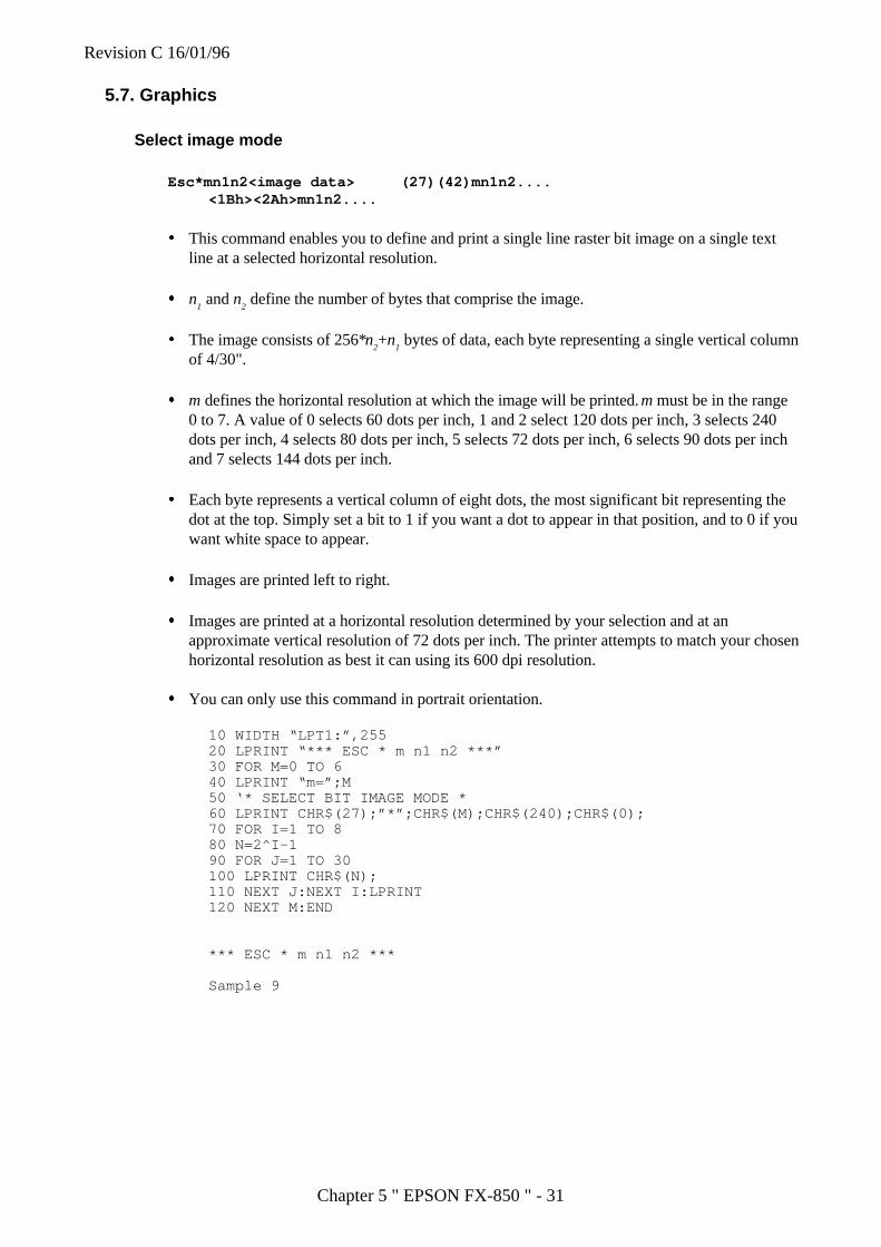
Revision C 16/01/96
Chapter 5 " EPSON FX-850 " - 31
5.7. Graphics
Select image mode
Esc*mn1n2<image data> (27)(42)mn1n2....<1Bh><2Ah>mn1n2....
� This command enables you to define and print a single line raster bit image on a single textline at a selected horizontal resolution.
� n1 and n
2 define the number of bytes that comprise the image.
� The image consists of 256*n2+n
1 bytes of data, each byte representing a single vertical column
of 4/30".
� m defines the horizontal resolution at which the image will be printed. m must be in the range0 to 7. A value of 0 selects 60 dots per inch, 1 and 2 select 120 dots per inch, 3 selects 240dots per inch, 4 selects 80 dots per inch, 5 selects 72 dots per inch, 6 selects 90 dots per inchand 7 selects 144 dots per inch.
� Each byte represents a vertical column of eight dots, the most significant bit representing thedot at the top. Simply set a bit to 1 if you want a dot to appear in that position, and to 0 if youwant white space to appear.
� Images are printed left to right.
� Images are printed at a horizontal resolution determined by your selection and at anapproximate vertical resolution of 72 dots per inch. The printer attempts to match your chosenhorizontal resolution as best it can using its 600 dpi resolution.
� You can only use this command in portrait orientation.
10 WIDTH “LPT1:”,25520 LPRINT “*** ESC * m n1 n2 ***”30 FOR M=0 TO 640 LPRINT “m=”;M50 ‘* SELECT BIT IMAGE MODE *60 LPRINT CHR$(27);”*”;CHR$(M);CHR$(240);CHR$(0);70 FOR I=1 TO 880 N=2^I-190 FOR J=1 TO 30100 LPRINT CHR$(N);110 NEXT J:NEXT I:LPRINT120 NEXT M:END
*** ESC * m n1 n2 ***
Sample 9
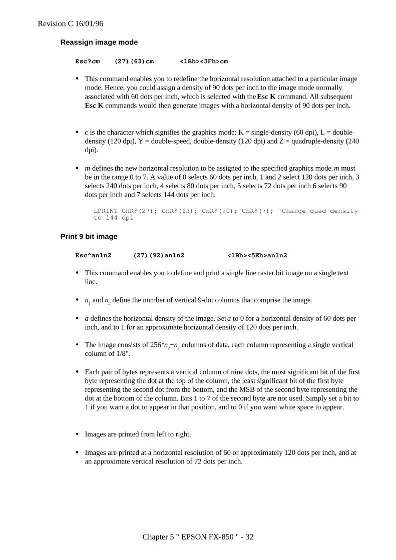
Revision C 16/01/96
Chapter 5 " EPSON FX-850 " - 32
Reassign image mode
Esc? cm (27)(63)cm <1Bh><3Fh>cm
� This command enables you to redefine the horizontal resolution attached to a particular imagemode. Hence, you could assign a density of 90 dots per inch to the image mode normallyassociated with 60 dots per inch, which is selected with the Esc K command. All subsequentEsc K commands would then generate images with a horizontal density of 90 dots per inch.
� c is the character which signifies the graphics mode: K = single-density (60 dpi), L = double-density (120 dpi), Y = double-speed, double-density (120 dpi) and Z = quadruple-density (240dpi).
� m defines the new horizontal resolution to be assigned to the specified graphics mode. m mustbe in the range 0 to 7. A value of 0 selects 60 dots per inch, 1 and 2 select 120 dots per inch, 3selects 240 dots per inch, 4 selects 80 dots per inch, 5 selects 72 dots per inch 6 selects 90dots per inch and 7 selects 144 dots per inch.
LPRINT CHR$(27); CHR$(63); CHR$(90); CHR$(7); 'Change quad densityto 144 dpi
Print 9 bit image
Esc^an1n2 (27)(92)an1n2 <1Bh><5Eh>an1n2
� This command enables you to define and print a single line raster bit image on a single textline.
� n1 and n
2 define the number of vertical 9-dot columns that comprise the image.
� a defines the horizontal density of the image. Set a to 0 for a horizontal density of 60 dots perinch, and to 1 for an approximate horizontal density of 120 dots per inch.
� The image consists of 256*n2+n
1 columns of data, each column representing a single vertical
column of 1/8".
� Each pair of bytes represents a vertical column of nine dots, the most significant bit of the firstbyte representing the dot at the top of the column, the least significant bit of the first byterepresenting the second dot from the bottom, and the MSB of the second byte representing thedot at the bottom of the column. Bits 1 to 7 of the second byte are not used. Simply set a bit to1 if you want a dot to appear in that position, and to 0 if you want white space to appear.
� Images are printed from left to right.
� Images are printed at a horizontal resolution of 60 or approximately 120 dots per inch, and atan approximate vertical resolution of 72 dots per inch.
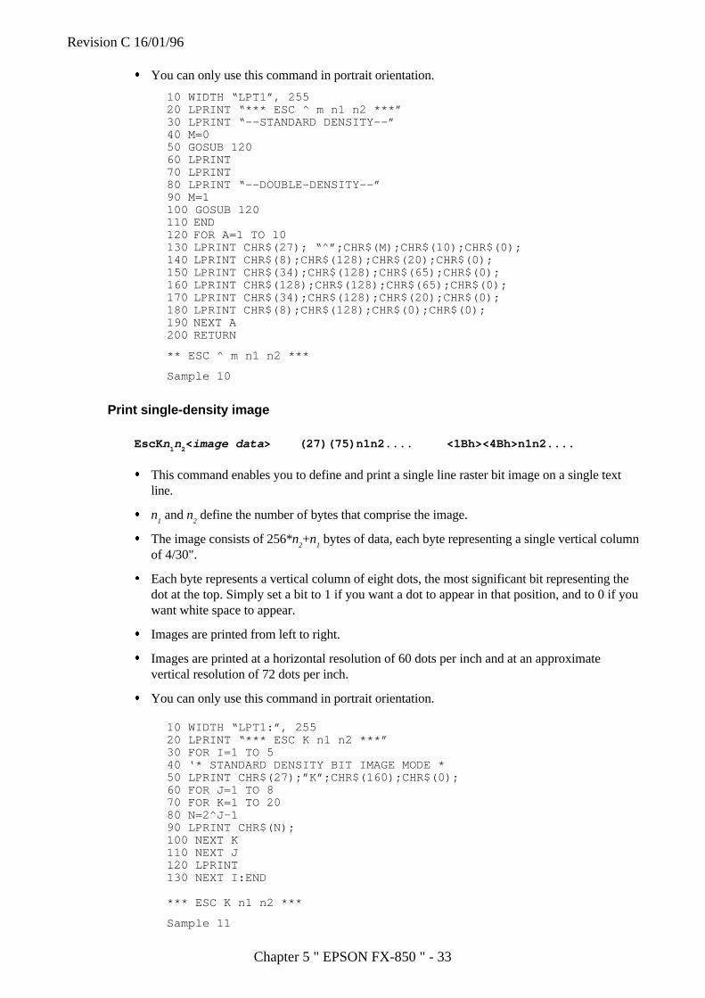
Revision C 16/01/96
Chapter 5 " EPSON FX-850 " - 33
� You can only use this command in portrait orientation.
10 WIDTH “LPT1”, 25520 LPRINT “*** ESC ^ m n1 n2 ***”30 LPRINT “--STANDARD DENSITY--”40 M=050 GOSUB 12060 LPRINT70 LPRINT80 LPRINT “--DOUBLE-DENSITY--”90 M=1100 GOSUB 120110 END120 FOR A=1 TO 10130 LPRINT CHR$(27); “^”;CHR$(M);CHR$(10);CHR$(0);140 LPRINT CHR$(8);CHR$(128);CHR$(20);CHR$(0);150 LPRINT CHR$(34);CHR$(128);CHR$(65);CHR$(0);160 LPRINT CHR$(128);CHR$(128);CHR$(65);CHR$(0);170 LPRINT CHR$(34);CHR$(128);CHR$(20);CHR$(0);180 LPRINT CHR$(8);CHR$(128);CHR$(0);CHR$(0);190 NEXT A200 RETURN
** ESC ^ m n1 n2 ***
Sample 10
Print single-density image
EscKn1n
2<image data > (27)(75)n1n2.... <1Bh><4Bh>n1n2....
� This command enables you to define and print a single line raster bit image on a single textline.
� n1 and n
2 define the number of bytes that comprise the image.
� The image consists of 256*n2+n
1 bytes of data, each byte representing a single vertical column
of 4/30".
� Each byte represents a vertical column of eight dots, the most significant bit representing thedot at the top. Simply set a bit to 1 if you want a dot to appear in that position, and to 0 if youwant white space to appear.
� Images are printed from left to right.
� Images are printed at a horizontal resolution of 60 dots per inch and at an approximatevertical resolution of 72 dots per inch.
� You can only use this command in portrait orientation.
10 WIDTH “LPT1:”, 25520 LPRINT “*** ESC K n1 n2 ***”30 FOR I=1 TO 540 ‘* STANDARD DENSITY BIT IMAGE MODE *50 LPRINT CHR$(27);”K”;CHR$(160);CHR$(0);60 FOR J=1 TO 870 FOR K=1 TO 2080 N=2^J-190 LPRINT CHR$(N);100 NEXT K110 NEXT J120 LPRINT130 NEXT I:END
*** ESC K n1 n2 ***
Sample 11
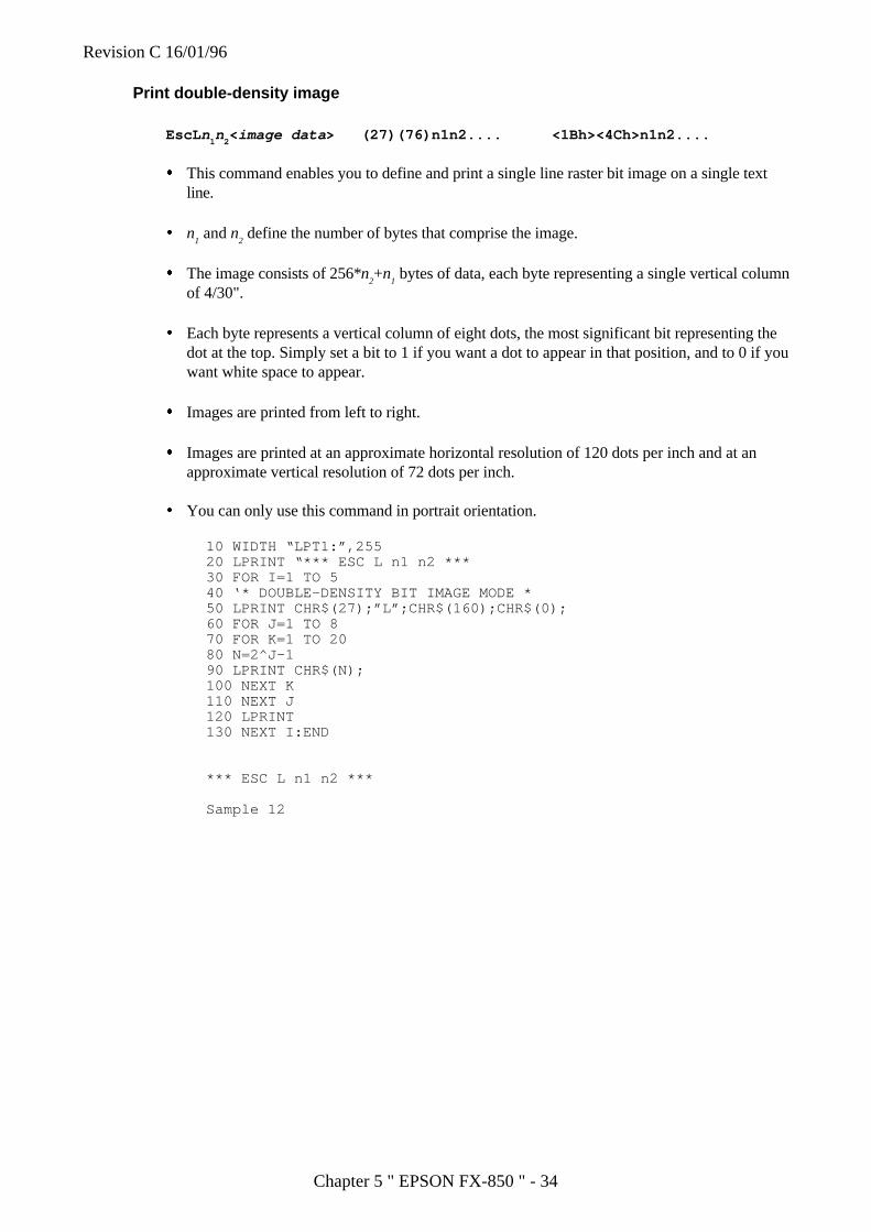
Revision C 16/01/96
Chapter 5 " EPSON FX-850 " - 34
Print double-density image
EscL n1n
2<image data > (27)(76)n1n2.... <1Bh><4Ch>n1n2....
� This command enables you to define and print a single line raster bit image on a single textline.
� n1 and n
2 define the number of bytes that comprise the image.
� The image consists of 256*n2+n
1 bytes of data, each byte representing a single vertical column
of 4/30".
� Each byte represents a vertical column of eight dots, the most significant bit representing thedot at the top. Simply set a bit to 1 if you want a dot to appear in that position, and to 0 if youwant white space to appear.
� Images are printed from left to right.
� Images are printed at an approximate horizontal resolution of 120 dots per inch and at anapproximate vertical resolution of 72 dots per inch.
� You can only use this command in portrait orientation.
10 WIDTH “LPT1:”,25520 LPRINT “*** ESC L n1 n2 ***30 FOR I=1 TO 540 ‘* DOUBLE-DENSITY BIT IMAGE MODE *50 LPRINT CHR$(27);”L”;CHR$(160);CHR$(0);60 FOR J=1 TO 870 FOR K=1 TO 2080 N=2^J-190 LPRINT CHR$(N);100 NEXT K110 NEXT J120 LPRINT130 NEXT I:END
*** ESC L n1 n2 ***
Sample 12
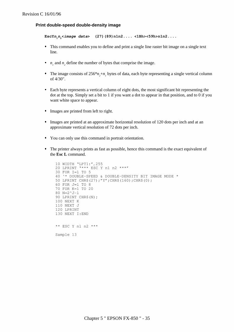
Revision C 16/01/96
Chapter 5 " EPSON FX-850 " - 35
Print double-speed double-density image
EscYn1n
2<image data > (27)(89)n1n2.... <1Bh><59h>n1n2....
� This command enables you to define and print a single line raster bit image on a single textline.
� n1 and n
2 define the number of bytes that comprise the image.
� The image consists of 256*n2+n
1 bytes of data, each byte representing a single vertical column
of 4/30".
� Each byte represents a vertical column of eight dots, the most significant bit representing thedot at the top. Simply set a bit to 1 if you want a dot to appear in that position, and to 0 if youwant white space to appear.
� Images are printed from left to right.
� Images are printed at an approximate horizontal resolution of 120 dots per inch and at anapproximate vertical resolution of 72 dots per inch.
� You can only use this command in portrait orientation.
� The printer always prints as fast as possible, hence this command is the exact equivalent ofthe Esc L command.
10 WIDTH “LPT1:”,25520 LPRINT “*** ESC Y n1 n2 ***”30 FOR I=1 TO 540 ‘* DOUBLE-SPEED & DOUBLE-DENSITY BIT IMAGE MODE *50 LPRINT CHR$(27);”Y”;CHR$(160);CHR$(0);60 FOR J=1 TO 870 FOR K=1 TO 2080 N=2^J-190 LPRINT CHR$(N);100 NEXT K110 NEXT J120 LPRINT130 NEXT I:END
** ESC Y n1 n2 ***
Sample 13
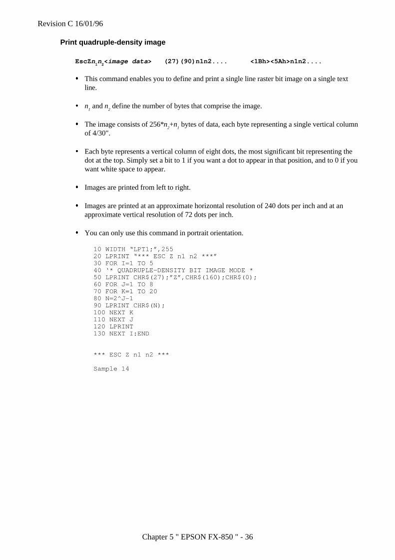
Revision C 16/01/96
Chapter 5 " EPSON FX-850 " - 36
Print quadruple-density image
EscZn1n
2<image data > (27)(90)n1n2.... <1Bh><5Ah>n1n2....
� This command enables you to define and print a single line raster bit image on a single textline.
� n1 and n
2 define the number of bytes that comprise the image.
� The image consists of 256*n2+n
1 bytes of data, each byte representing a single vertical column
of 4/30".
� Each byte represents a vertical column of eight dots, the most significant bit representing thedot at the top. Simply set a bit to 1 if you want a dot to appear in that position, and to 0 if youwant white space to appear.
� Images are printed from left to right.
� Images are printed at an approximate horizontal resolution of 240 dots per inch and at anapproximate vertical resolution of 72 dots per inch.
� You can only use this command in portrait orientation.
10 WIDTH “LPT1;”,25520 LPRINT “*** ESC Z n1 n2 ***”30 FOR I=1 TO 540 ‘* QUADRUPLE-DENSITY BIT IMAGE MODE *50 LPRINT CHR$(27);”Z”,CHR$(160);CHR$(0);60 FOR J=1 TO 870 FOR K=1 TO 2080 N=2^J-190 LPRINT CHR$(N);100 NEXT K110 NEXT J120 LPRINT130 NEXT I:END
*** ESC Z n1 n2 ***
Sample 14
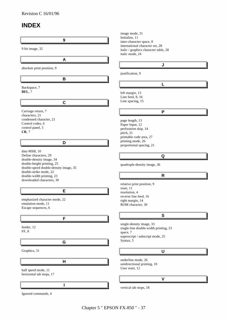
Revision C 16/01/96
Chapter 5 " EPSON FX-850 " - 37
INDEX
9
9 bit image, 32
A
absolute print position, 9
B
Backspace, 7BEL , 7
C
Carriage return, 7characters, 21condensed character, 21Control codes, 6control panel, 5CR, 7
D
data MSB, 10Define characters, 29double-density image, 34double-height printing, 25double-speed double-density image, 35double-strike mode, 22double-width printing, 23downloaded characters, 30
E
emphasized character mode, 22emulation mode, 11Escape sequences, 6
F
feeder, 12FF, 8
G
Graphics, 31
H
half speed mode, 11horizontal tab stops, 17
I
Ignored commands, 4
image mode, 31Initialize, 11inter-character space, 8international character set, 28italic / graphics character table, 28italic mode, 24
J
justification, 9
L
left margin, 13Line feed, 8, 16Line spacing, 15
P
page length, 13Paper Input, 12perforation skip, 14pitch, 21printable code area, 27printing mode, 26proportional spacing, 21
Q
quadruple-density image, 36
R
relative print position, 9reset, 11resolution, 4reverse line feed, 16right margin, 14ROM character, 30
S
single-density image, 33single-line double-width printing, 23space, 7superscript / subscript mode, 25Syntax, 5
U
underline mode, 26unidirectional printing, 10User reset, 12
V
vertical tab stops, 18
Revision C 16/01/96
Chapter 6 " IBM Proprinter XL " - 1
Chapter 6
IBM Proprinter XL
Revision C 16/01/96
Chapter 6 " IBM Proprinter XL " - 2
Command listNUL Null 5BEL Bell 5ESC Escape 6SP Space 6BS Backspace 6LF Line Feed 6FF Form Feed 6CR Carriage return 7Esc5n Automatic line feed 7DC1 Enable printer 7EscQ22 Disable printer 7EscQ3 7EscCRmode Reset printer / change emulation mode 8EscCR!#R User reset 8EscEMn Paper Input Control 8EscCn Set page length 9EscCNULn Set page length 9EscXmn Set left and right margins 9EscNn Set perforation skip 10EscO Cancel perforation skip 10Esc0 Select 1/8" line spacing 10Esc1 Select 7/72" line spacing 10EscAn Select n/72" line spacing 11Esc2 Activate n/72" line spacing 11Esc3n Set n/216" line feed 11EscJn Execute n/216" line feed 11EscDn1n2n3...NUL 12
Set horizontal tab stopsEscBn1n2n3...NUL 12
Set vertical tab stopsHT Horizontal tab 12VT Vertical tab 12EscR Restore default tab settings 13Esc7 Select character set I 13Esc6 Select character set II 13DC2 Set pitch to 10 cpi 13Esc: Set pitch to 12 cpit 13EscPn Proportional spacing 14SI Set condensed character mode 14EscE Set emphasized character mode 14EscF Cancel emphasized character mode 14SO Set enlarged character mode for a single line 15DC4 Cancel enlarged character mode 15CAN Cancel 15EscWn Enlarged character mode 15EscSn Set superscript or subscript character mode 16EscT Cancel superscript or subscript character mode 16Esc-n Underline mode 16Esc_n Continuous overline mode 16Esc[@n1n2n3n4n5n6 17
Select double-height / double-width modeEsc\n1n2<character data> 17
Select character from the all character code tableEsc^<char-code> Select a character from the all character code table 17EscI Select character font 18
Revision C 16/01/96
Chapter 6 " IBM Proprinter XL " - 3
Esc=n1n220n3(n4n5<character definition data>...) 18Define characters
EscKn1n2<image data> 19Set single-density image mode
EscLn1n2<image data> 20Set double-density image mode
EscYn1n2<image data> 20Set double-speed, double-density image mode
EscZn1n2<image data> 21
Revision C 16/01/96
Chapter 6 " IBM Proprinter XL " - 4
1. IntroductionThis HL Series printer offers a complete emulation of the IBM Proprinter. In Proprinter XL modeyou can drive the printer directly by incorporating control codes and escape sequences in yourprogram, or alternatively, applications software (for example, your word-processing software)may send the necessary commands to the printer automatically. Check the manual that came withyour software package for instructions on how to use your software with an IBM Proprinter XL.
2. Emulation detailsThe following points should be borne in mind when running this HL Series printer in IBMProprinter XL mode.
2.1. Ignored commands
A few IBM Proprinter XL commands have reduced effect, or no effect at all. In some cases this isdue to the physical nature of an HL Series printer. These commands are as follows. The BELcontrol code (ASCII 7) which is used to sound the Proprinter’s bell, is ignored. The DC3 controlcode (ASCII 23), used to disable the Proprinter, is also ignored. The Esc Y escape sequence,which enables double-speed, double-density graphics mode has no effect on the printing speed, asHL Series printers always operate as fast as they can. Hence the Esc Y has the same effect as theEsc L (enable double-density graphics mode) sequence.
2.2 Resolution
The resolution of this HL Series printer is 600 dots per inch. Some IBM Proprinter use fractionsof an inch that not exactly divisible by 600, for example Esc 0 sets line spacing to 1/8" of an inch.Similarly, the Proprinter graphics commands specify resolutions of 72, 120 and 240 dots perinch. When a graphic cannot be represented exactly at 600 dots per inch the printer prints theclosest possible approximation to the specified image using 600 dots per inch.
2.3 Character set selection
Using software commands you can select IBM character set I, IBM character set II or the IBMAll Character Code table. Using the printer control panel you can select a number of othercharacter sets (consult the User's Guide for a description of how to do this). All availablecharacter sets are shown in the IBM Proprinter XL mode section of the appendix at the end ofthis manual.
2.4 Controlling the printer
Commands are invoked using either control codes or escape sequences. You can send them tothe printer as part of a program, using the same command that you would use to print a textstring on the printer, for example in BASIC you would use the LPRINT command.
2.5 Control codes
Control codes are ASCII codes that tell the printer to perform a particular function, such as aline feed. Send a control code to the printer by sending the same type of instruction you woulduse to print a character using its ASCII code number. For example, the ASCII code for a formfeed is 12, so to get the printer to perform a form feed use the following BASIC statement:
LPRINT CHR$(12);
The CHR$ operator is normally used to convert an ASCII code into its corresponding character.
Revision C 16/01/96
Chapter 6 " IBM Proprinter XL " - 5
2.6 Escape sequences
Escape sequences tell the printer which Proprinter function to perform. An escape sequenceconsists of the ESC character followed by one or more characters which define the operation to beperformed. Send an escape sequence to the printer by sending the same type of instruction youwould use to print characters using their ASCII codes. Some escape sequences require parametervalues or data following them, for example commands which turn a particular feature on and off,and commands for downloading character descriptions to the printer or for printing graphicimages. Numerical parameter data, too, is sent to the printer as if it were a character code to beprinted. For example, to set the left and right margin settings to be at 10 and 70 columns acrossthe page the required escape sequence is Esc X 10 70. In BASIC this would be:
LPRINT CHR$(27); CHR$(88); CHR$(10); CHR$(70);
3. Notation used in this emulation description
3.1 Syntax
The following conventions are used in this description of the Proprinter XL software commands.A letter, word or number in upright bold text is the literal character which and should be sent tothe printer as a character code.A letter or word in italics is a variable and you must substitute the appropriate value or valueswhen using the command.An ellipsis, ..., indicates that an element may be repeated any number of times.
3.2 Data conventions
The bits that comprise a byte of data are numbered 1 to 8. Bit 1 is the least significant bit (LSB)and bit 8 is the most significant bit (MSB).
4. Commands
4.1 Basic printer operation
The most common printer operations are described in this section. Most are invoked usingcontrol codes. For the sake of completeness three instructions which HL Series printers ignore areincluded.
Null
NUL (0) <0h>
� NUL (ASCII 0) is ignored.
Bell
BEL (07) <07h>
� BEL (ASCII 7) is ignored.
Revision C 16/01/96
Chapter 6 " IBM Proprinter XL " - 6
Escape
ESC (27) <1Bh>
� The ESC control code (ASCII 27) marks the start of an escape sequence.
LPRINT CHR$(27);
Space
SP (32) <20h>
� The SP control code (ASCII 32) moves the current print position one space to the right.
LPRINT CHR$(32);
Backspace
BS (08) <08h>
� The BS control code (ASCII 8) moves the current print position one space to the left.
LPRINT CHR$(8);
Line feed
LF (10) <0Ah>
� The LF control code (ASCII 10) moves the current print position down one line.
LPRINT CHR$(10);
Form feed
FF (12) <0Ch>
� The FF control code (ASCII 12) ejects the current page (unless it is blank) and moves thecurrent print position to the top of the next page.
� If the current page is blank this control code has no effect.
LPRINT CHR$(12);
Revision C 16/01/96
Chapter 6 " IBM Proprinter XL " - 7
Carriage return
CR (13) <0Dh>
� The CR control code (ASCII 13) moves the current print position to the left margin on thecurrent line.
� If automatic line feed is ON, this code moves the current print position to the left margin onthe next line.
LPRINT CHR$(13);
Automatic line feed
Esc5n (27)(53)n <1Bh><35h>n
� When automatic line feed is ON, a line feed is automatically performed every time a carriagereturn is sent to the printer.
� To turn the automatic line feed function ON, set n to 1.
� To turn the automatic line feed function OFF, set n to 0.
LPRINT CHR$(27); CHR$(53); CHR$(1); 'Turn auto line feed on
Enable printer
DC1 (17) (11h>
� The DC1 control code (ASCII 17) enables the printer to accept data for printing again after adisable printer instruction.
LPRINT CHR$(17);
Disable printer
EscQ22 (27)(81)(50)(50) <1Bh><51h><32h><32h>
or
EscQ3 (27)(81)(51) <1Bh><51h><32h>
� These two commands stop the printer from accepting any data for printing or any controlcodes until it has received a DC1 code (enable printer).
� The DC3 code (ASCII 19) is not recognized by the printer.
LPRINT CHR$(27); CHR$(81); CHR$(22); 'Disable printer
Revision C 16/01/96
Chapter 6 " IBM Proprinter XL " - 8
Change emulation mode
EscCR<mode> (27)(13)mode <1Bh><0Dh>mode
� This command changes the printer emulation mode or performs a reset.
� mode can be ‘E’ (Epson), ‘P’ or ‘D’ (Diablo), ‘H’ (Laserjet 4), ‘I’ (IBM Proprinter XL), 'AB'(BR-Script Batch), 'AI' (BR-Script Interactive), 'GL' (HP-GL) or ‘FD’ (factory default).
� On receiving this command the printer prints any remaining data and performs a page eject(unless the current page is blank). The new emulation mode default settings come into effect,except when the mode is set to ‘FD’.
� If you set the mode to ‘FD’ to reset the printer to its factory default settings, Laserjet 4 mode(the factory default emulation mode) is selected and the Laserjet 4 factory default environmentis restored. For a list of the factory default settings see the sub-section “Factory defaultenvironment” in the Chapter 2 "PCL" of this manual.
� Selecting IBM Proprinter XL emulation with mode = ‘I’ causes the printer to be reset.
LPRINT CHR$(27); CHR$(13); CHR$(69); 'Change to Epson emulation
User Reset
EscCR!#R (27)(13)(33)#(82) <1Bh><0Dh><21h>#<52h>
� # = 0, restores to the current user setting.
� # = 1, restores to User settings 1.
� # = 2, restores to User settings 2.
Paper Input Control
EscEMn (27)(25)n <1Bh><19h>n
� n = 0, paper is fed from manual paper feeder.
� n = 1, paper is fed from the standard paper cassette.
� n = 2, paper is fed from the optional lower paper cassette.
� n = 3, printer ejects the sheet of paper.
Revision C 16/01/96
Chapter 6 " IBM Proprinter XL " - 9
4.2 Page format
Set page length
EscCn (27)(67)n <1Bh><43h>n
� This command sets the page length in lines.
or
EscCNULn (27)(67)(0)n <1Bh><43h><00h>n
� This command sets the page length in inches.
� n is the number of lines that make up one page, or the length of the page in inches, accordingto the form of the command.
� If the first form of the command is used (n = the number of lines in the page) the current linespacing setting is used to determine the length of the page.
� If the first form of the command is used, n must be in the range 1 to 255.
� If the second form of the command is used ( n = page length in inches ), n must be in therange 1 to 14.
LPRINT CHR$(27); CHR$(81); CHR$(22); 'Disable printer
Set left and right margins
EscXmn (27)(88)mn <1Bh><88h>mn
� This command sets the left and right margins.
� m = the number of character positions at the current pitch (characters per inch) between theleft edge of the page and the left margin.
� n = the number of character positions at the current pitch between the left edge of the page andthe right margin.
� If you set m = 0 the current left margin setting is retained.
� If you set n = 0 the current right margin setting is retained.
LPRINT CHR$(18); 'Set pitch to 10 CPILPRINT CHR$(27); CHR$(88); CHR$(10); CHR$(70); 'Set margins to 1"and 7"
Revision C 16/01/96
Chapter 6 " IBM Proprinter XL " - 10
Set perforation skip
EscNn (27)(78)n <1Bh><4Eh>n
� This command sets the bottom margin and enables perforation skip, that is, whenever theprint position reaches the bottom margin the printer performs a page eject and moves the printposition to the top of the next page.
� n = the number of lines at the current line space setting between the bottom edge of the pageand the bottom margin.
� n must be in the range 1 to 255.
� Esc C (set page length) and Esc O(Cancel perforation skip) cancel automatic perforationskip.
� If the bottom margin is set to be above the top margin, the top margin is discarded and oneline is enabled for printing.
LPRINT CHR$(27); CHR$(78); CHR$(4); 'Set bottom margin to 4 lines.
Cancel perforation skip
EscO (27)(79) <1Bh><4Fh>
� This command cancels the automatic perforation skip feature.
LPRINT CHR$(27); CHR$(79); 'Cancel perforation skip.
Line spacing and tabs
Set 1/8" line spacing
Esc0 (27)(48) <1Bh><30h>
� This command sets the line spacing to 1/8". All subsequent line feed operations will move theprint position 1/8" down the page.
LPRINT CHR$(27); CHR$(48); 'Set line spacing to 1/8".
Set 7/72" line spacing
Esc1 (27)(48) <1Bh><31h>
� This command sets the line spacing to 7/72". All subsequent line feed operations will movethe print position 7/72" down the page.
� Since the printer's resolution is 600 dots per inch the line spacing will not be exactly 7/72".
LPRINT CHR$(27); CHR$(49); 'Set line spacing to 7/72".
Revision C 16/01/96
Chapter 6 " IBM Proprinter XL " - 11
Save n/72" line spacing
EscAn (27)(65)n <1Bh><41h>n
� This command allows you to select a line spacing of n/72". Your selection does not takeeffect until you activate it with the Esc 2 command.
� Since the printer's resolution is 600 dots per inch the line spacing may not be exactly n/72".
� n must be in the range 1 to 85.
� If n is outside the range 1 to 85 the default line spacing, 1/6" is selected.
LPRINT CHR$(27); CHR$(65); CHR$(10); 'Select line spacing of10/72".
Activate n/72" line spacing
Esc2 (27)(50) <1Bh><32h>
� This command allows you to activate the line spacing setting you specified with the Esc Acommand.
LPRINT CHR$(27); CHR$(50); 'Activate selected line spacing ofn/72".
Set n/216" line spacing
Esc3n (27)(51)n <1Bh><33h>n
� This command sets the line spacing to n/216". All subsequent line feed operations will movethe print position n/216" down the page.
� Since the printer's resolution is 600 dots per inch the line spacing may not be exactly n/216".
� n must be in the range 1 to 255.
LPRINT CHR$(27); CHR$(51); CHR$(25); 'Select line spacing of25/216".
Execute n/216" line spacing
EscJn (27)(74)n <1Bh><4Ah>n
� This command moves the print position one line down the page using a line spacing of n/216".
� The existing line space setting is not affected.
LPRINT CHR$(27); CHR$(50); CHR$(30); 'Move print position down30/216".
Revision C 16/01/96
Chapter 6 " IBM Proprinter XL " - 12
Set horizontal tabs
EscD<n1><n2><n3>...NUL (27)(68)n1n2n3...(00)<1Bh><44h>n1n2n3...<00h>
� This command enables you to set up to 28 horizontal tab stops using the current characterpitch.
� The tab stops should be set in ascending order.
� Esc D 0 clears all horizontal tab settings.
� Esc R restores the default settings, which are at every eighth column, starting at the ninthcolumn.
� You can move the print position to the tab stops using the HT control code.
LPRINT CHR$(27); CHR$(68); CHR$(10); CHR$(20); CHR$(0); 'Set tabstops at columns 10 and 20.
Set vertical tabs
EscB<n1><n2><n3> ...NUL (27)(66)n1n2n3...(00)<1Bh><42h>n1n2n3...<00h>
� This command enables you to set up to 64 vertical tab stops using the line feed pitch.
� The tab stops should be set in ascending order.
� Esc B 0 and Esc R both clear all vertical tab settings.
� You can move the print position to the tab stops using the VT control code.
LPRINT CHR$(27); CHR$(66); CHR$(12); CHR$(24); CHR$(0); 'Set tabstops at lines 12 and 24.
Horizontal tab
HT (09) <09h>
� The HT control code (ASCII 9) moves the current print position one tab stop to the right.
� The command is ignored if there are no tab stops to the right of the current print position or ifthe next tab stop is beyond the right margin.
LPRINT CHR$(9);
Vertical tab
VT (11) <0Bh>
� The VT control code (ASCII 11) moves the current print position one vertical tab stop downthe page.
� If there are no tab stops below the current print position a line feed is performed.
� If no tab stops have been set a line feed is performed.
LPRINT CHR$(9);
Revision C 16/01/96
Chapter 6 " IBM Proprinter XL " - 13
Restore default tab settings
EscR (27)(82) <1Bh><52h>
� This command restores the default horizontal tab settings which are at every eight columns,starting at the ninth column. There are no default vertical tab settings.
LPRINT CHR$(27); CHR$(82); 'Restore default tab stops.
4.3 Using characters
Select character set I
Esc7 (27)(55) <1Bh><37h>
� This command selects IBM Character set I for use in subsequent printing operations.
LPRINT CHR$(27); CHR$(55); 'Select character set I
Select character set II
Esc6 (27)(56) <1Bh><36h>
� This command selects IBM character set II for use in subsequent printing operations.
LPRINT CHR$(27); CHR$(54); 'Select character set II
Set pitch to 10 cpi
DC2 (18) <12h>
� This command sets the printing pitch to 10 characters per inch (cpi).
� If condensed character mode has previously been set, it is cancelled.
LPRINT CHR$(18); 'set pitch to 10 CPI
Set pitch to 12 cpi
Esc: (27)(58) <1Bh><3Ah>
� This command sets the printing pitch to 12 characters per inch (cpi).
LPRINT CHR$(27); CHR$(58); 'set pitch to 12 CPI
Revision C 16/01/96
Chapter 6 " IBM Proprinter XL " - 14
Proportional spacing
EscPn (27)(80)n <1Bh><50h>n
� This command allows you to turn proportional spacing on or off.
� Setting n to 1 turns proportional spacing on. Subsequent text is printed proportionally spaced.
� Setting n to 0 turns proportional spacing off. Subsequent text is printed monospaced.
� If you change the character pitch using DC2, SI or Esc :, proportional spacing isautomatically turned off.
LPRINT CHR$(27); CHR$(80); CHR$(1); 'Turn proportional spacing on
Set condensed character mode
SI (15) <0Fh>
� This command selects condensed character mode. Subsequent text characters are condensedhorizontally when printed.
� The DC2 code, used to select a character pitch of 10 cpi, cancels condensed character mode.
LPRINT CHR$(15); 'Set condensed character mode
Set emphasized character mode
EscE (27)(69) <1Bh><45h>
� This command turns emphasized character mode on. Subsequent text is printed with a boldstroke width.
LPRINT CHR$(27); CHR$(69); 'Turn emphasized character mode on
Cancel emphasized character mode
EscF (27)(70) <1Bh><46h>
� This command turns emphasized character mode off. Subsequent text is printed with mediumstroke width.
LPRINT CHR$(27)l CHR$(70); 'Turn emphasized character mode off
Revision C 16/01/96
Chapter 6 " IBM Proprinter XL " - 15
Set enlarged character mode for a single line
SO (14) <0Eh>
� This command turns enlarged character mode on for one line only. The subsequent line of textis printed using double-width characters and with the line space setting doubled.
� The following commands cancel enlarged character mode set using the SO control code: CR,CAN, LF , FF, VT , Esc W 0, DC4 and Esc [@.
LPRINT CHR$(14); 'Set enlarged character mode for one line
Cancel enlarged character mode
DC4 (20) <14h>
� This control code cancels the single-line enlarged character mode set with the SO controlcode. Subsequent text is printed using normal sized characters. The previous line spacingsetting is restored.
� The previous character pitch is restored.
LPRINT CHR$(20); 'Cancel enlarged character mode set with SO
Cancel
CAN (24) <18h>
� This control code cancels single-line enlarged character mode set with the SO control code.Subsequent text is printed using normal sized characters and the previous line spacing settingis restored.
LPRINT CHR$(24); 'Cancel enlarged character mode set with SO
Enlarged character mode
EscWn (27)(87)n <1Bh><57h>n
� This command turns enlarged character mode on or off.
� If n is set to 1 subsequent text is printed using double-width characters. The line spacingsetting is doubled.
� If n is set to 0 subsequent text is printed using normal sized characters. The previous linespacing and character pitch settings are restored.
� Only Esc W 0 can be used to cancel enlarged character mode set using the Esc W 1instruction.
� Esc W 0 cancels enlarged character mode set using the Esc W 1 instruction, the SO controlcode or the Esc [@ instruction.
LPRINT CHR$(27); CHR$(87); CHR$(1); 'Set enlarged character mode
Revision C 16/01/96
Chapter 6 " IBM Proprinter XL " - 16
Set superscript or subscript character mode
EscSn (27)(83)n <1Bh><53h>n
� This command allows you to print superscripts or subscripts.
� Set n to 0 to print subsequent text using superscript characters.
� Set n to 1 to print subsequent text using subscript characters.
LPRINT CHR$(27); CHR$(83); CHR$(1); 'Turn on subscript mode
Cancel superscript or subscript character mode
EscT (27)(84) <1Bh><54h>
� This command stops superscript or subscript printing if either had been enabled.
� Subsequent text is printed using normal characters.
LPRINT CHR$(27); CHR$(84); 'Turn off superscript/subscript mode
Underline mode
Esc-n (27)(126)n <1Bh><7Eh>n
� This command turns character underlining on or off.
� If n is set to 1 subsequent text is underlined.
� Horizontal tab spaces are not underlined irrespective of whether underlining mode is on or off.
� If n is set to 0 subsequent text is not underlined.
LPRINT CHR$(27); CHR$(45); CHR$(1); 'Underline following text
Continuous overline mode
Esc_n (27)(95))n <1Bh><5Fh>n
� This command turns character overline printing on or off.
� If n is set to 1 subsequent text is printed with a continuous line above it.
� Horizontal tab spaces are not printed overlined irrespective of whether overline printing modeis on or off.
� If n is set to 0 subsequent text is not printed with an overline.
LPRINT CHR$(27); CHR$(95); CHR$(1); 'Print following text with anoverline
Revision C 16/01/96
Chapter 6 " IBM Proprinter XL " - 17
Select double-height / double-width mode
Esc[@n1n2n3n4n5n6 (27)(91)(64)n1n2n3n4n5n6<1Bh><5Bh><40h>n1n2n3n4n5n6
� This command enables you to select single or double line spacing and single or doublecharacter height and width.
� n1 should be set to 4 and n2,n3 and n4 to 0.
� To set double line spacing and select double-height characters set n5 to 34.
� To set double line spacing and select normal height characters set to n5 to 33.
� To set single line spacing and select double-height characters set to n5 to 18.
� To set single line spacing and select normal height characters set n5 to 17.
� To select double-width characters set n6 to 2.
� To select single-width characters set n6 to 1.
LPRINT CHR$(27); CHR$(91); CHR$(64); CHR$(4); CHR$(0); CHR$(0);CHR$(0); CHR$(34); CHR$(1); 'Set double line spacing and printdouble-height, double-width characters.
Select character from the All character Code table
Esc\n1n2<Character data> (27)(92)n1n2<Character data><1Bh><5Ch>n1n2<Character data>
� This command enables you to print characters from the All Character Code table.
� n1 and n2 specify the number of characters to be printed.
� The number of characters printed is 256*n2+n1.
� Control codes included in the character data are not executed.
LPRINT CHR$(27); CHR$(92); CHR$(64); CHR$(1); CHR$(65); CHR$(66);CHR$(67); CHR$(68); CHR$(69); 'Print 320 characters startingABCDE...
Select a character from the All Character Code table
Esc^<char-code> (27)(94)<Char-code> <1Bh><5Eh><Char-code>
� This command enables you to print a single character from the All Character Code table.
� A control code is not executed if the code is sent immediately following this instruction.
LPRINT CHR$(27); CHR$(94); CHR$(36); 'Printed a dollar sign
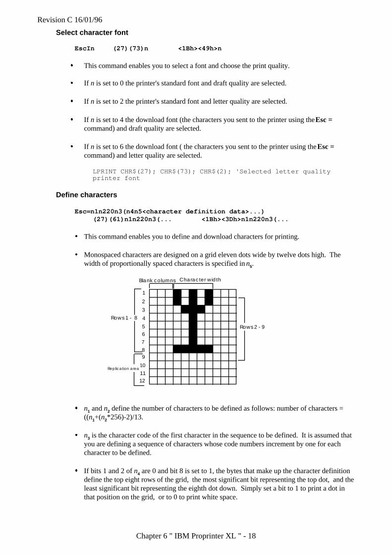
Revision C 16/01/96
Chapter 6 " IBM Proprinter XL " - 18
Select character font
EscIn (27)(73)n <1Bh><49h>n
� This command enables you to select a font and choose the print quality.
� If n is set to 0 the printer's standard font and draft quality are selected.
� If n is set to 2 the printer's standard font and letter quality are selected.
� If n is set to 4 the download font (the characters you sent to the printer using the Esc =command) and draft quality are selected.
� If n is set to 6 the download font ( the characters you sent to the printer using the Esc =command) and letter quality are selected.
LPRINT CHR$(27); CHR$(73); CHR$(2); 'Selected letter qualityprinter font
Define characters
Esc=n1n220n3(n4n5<character definition data>...)(27)(61)n1n220n3(... <1Bh><3Dh>n1n220n3(...
� This command enables you to define and download characters for printing.
� Monospaced characters are designed on a grid eleven dots wide by twelve dots high. Thewidth of proportionally spaced characters is specified in n5.
1
2
3
4
56
7
89
10
1112
Blank columns Character width
Rows 1 - 8
Replication area
Rows 2 - 9
� n1 and n2 define the number of characters to be defined as follows: number of characters =((n1+(n2*256)-2)/13.
� n3 is the character code of the first character in the sequence to be defined. It is assumed thatyou are defining a sequence of characters whose code numbers increment by one for eachcharacter to be defined.
� If bits 1 and 2 of n4 are 0 and bit 8 is set to 1, the bytes that make up the character definitiondefine the top eight rows of the grid, the most significant bit representing the top dot, and theleast significant bit representing the eighth dot down. Simply set a bit to 1 to print a dot inthat position on the grid, or to 0 to print white space.
Revision C 16/01/96
Chapter 6 " IBM Proprinter XL " - 19
� If bits 1 and 2 of n4 are 00 and bit 8 is set to 0 the bytes that make up the character definitiondefine rows 2 to 9 of the grid, the most significant bit representing the second dot, and theleast significant bit representing the ninth dot down. Simply set a bit to 1 to print a dot in thatposition on the grid, or to 0 to print white space.
� If bits 1 and 2 of n4 are 01 the least significant bit of each data byte is replicated in rows 9 to12 of the grid.
� If bits 1 and 2 of n4 are 10 the bits 1 to 4 of each data byte are replicated in rows 9 to 12 ofthe grid.
� Bits 5 to 7 of n5 specify the number of columns left blank to the left of the defined character inproportional spacing mode. Up to seven columns can be skipped.
� Bits 1 to 4 of n5 specify the width in columns of the defined character in proportional spacingmode. Up to fifteen columns can be used to define the character.
� Downloaded characters are selected using the Esc I command and then printed by sending theappropriate character codes.
4.4 Graphics
Set single-density image mode
EscKn1n2<image data > (27)(75)n1n2<image data><1Bh><4Bh>n1n2<image data>
� This command enables you to define and print a single line raster bit image on a single textline.
� n1 and n2 define the number of bytes that comprise the image.
� The image consists of 256*n2+n1 bytes of data, each byte representing a single vertical columnof 4/30".
� Images are printed left to right.
� Images are printed at a horizontal resolution of 60 dots per inch and at an approximatevertical resolution of 72 dots per inch.
� Each byte represents a vertical column of eight dots, the most significant bit representing thedot at the top. Simply set a bit to 1 if you want a dot to appear in that position, and to 0 ifyou want white space to appear.
10 WIDTH "LPT1:", 25520 LPRINT "*** ESC K n1 n2 ***";CHR$(10);30 FOR i=1 TO 540 '* STANDARD DENSITY BIT IMAGE MODE *50 LPRINT CHR$(27);"K";CHR$(160);CHR$(0);60 FOR J=1 TO 870 FOR K=1 TO 2080 N=2^J-190 LPRINT CHR$(N);100 NEXT K110 NEXT J120 LPRINT CHR$(10);130 NEXT I:END
< Sample 15 >

Revision C 16/01/96
Chapter 6 " IBM Proprinter XL " - 20
Set double-density image mode
EscL n1n2<image data > (27)(76)n1n2<image data><1Bh><4Ch>n1n2<image data>
� This command enables you to define and print a single line raster bit image on a single textline.
� n1 and n2 define the number of bytes that comprise the image.
� The image consists of 256*n1+n2 bytes of data, each byte representing a single verticalcolumn of 4/30".
� Images are printed left to right.
� Images are printed at an approximate horizontal resolution of 120 dots per inch and at anapproximate vertical resolution of 72 dots per inch.
� Each byte represents a vertical column of eight dots, the most significant bit representing thedot at the top. Simply set a bit to 1 if you want a dot to appear in that position, and to 0 ifyou want white space to appear.
10 WIDTH "LPT1:", 25520 LPRINT "***ESC L n1 n2 ***"CHR$(10);30 FOR I=1 TO 540 '*DOUBLE-DENSITY BIT IMAGE MODE *50 LPRINT CHR$(27);"L";CHR$(160);CHR$(0);60 FOR J=1 TO 870 FOR K=1 TO 2080 N=2^J-190 LPRINT CHR$(N);100 NEXT K110 NEXT J120 LPRINT CHR$(10);130 NEXT I:END
< Sample 16 >
Set double-speed, double-density image mode
EscYn1n2<image data > (27)(89)n1n2<image data><1Bh><59h>n1n2<image data>
� This command enables you to define and print a single line raster bit image on a single textline.
� n1 and n2 define the number of bytes that comprise the image.
� The image consists of 256*n2+n1 bytes of data, each byte representing a single verticalcolumn of 4/30".
� Images are printed left to right.
� Images are printed at an approximate horizontal resolution of 120 dots per inch and at anapproximate vertical resolution of 72 dots per inch.
� Each byte represents a vertical column of eight dots, the most significant bit representing thedot at the top. Simply set a bit to 1 if you want a dot to appear in that position, and to 0 ifyou want white space to appear.
Revision C 16/01/96
Chapter 6 " IBM Proprinter XL " - 21
� This printer always prints as fast as possible, hence this command is the exact equivalent ofthe Esc L command.
10 WIDTH "LPT1:", 25520 LPRINT "*** ESC Y n1 n2 ***", CHR$(10);30 FOR I=1 TO 540 '*DOUBLE-SPEED & DOUBLE-DENSITY BIT IMAGE MODE *50 LPRINT CHR$(27);"Y";CHR$(160);CHR$(0);60 FOR J=1 TO 870 FOR k=1 TO 2080 N=2^J-190 LPRINT CHR$(N);100 NEXT K110 NEXT J120 LPRINT CHR$(10);130 NEXT I:END
< Sample 17 >
Set quadruple-density image mode
EscZn1n2<image data > (27)(90)n1n2<image data><1Bh><5Ah>n1n2<image data>
� This command enables you to define and print a single line raster bit image on a single textline.
� n1 and n2 define the number of bytes that comprise the image.
� The image consists of 256*n1+n2 bytes of data, each byte representing a single verticalcolumn of 4/30".
� Images are printed left to right.
� Images are printed at an approximate horizontal resolution of 240 dots per inch and at anapproximate vertical resolution of 72 dots per inch.
� Each byte represents a vertical column of eight dots, the most significant bit representing thedot at the top. Simply set a bit to 1 if you want a dot to appear in that position, and to 0 ifyou want white space to appear.
10 WIDTH "LPT1:",25520 LPRINT "*** ESC Z n1 n2 ***";CHR$(10);30 FOR I=1 TO 540 '* QUADRUPLE-DENSITY BIT IMAGE MODE *50 LPRINT CHR$(27);"Z";CRH$(16);CHR$(0);60 FOR J=1 TO 870 FOR K=1 TO 2080 N=2^J-190 LPRINT CHR$(N);100 NEXT K110 NEXT J120 LPRINT CHR$(10);130 NEXT I:END
< Sample 18 >
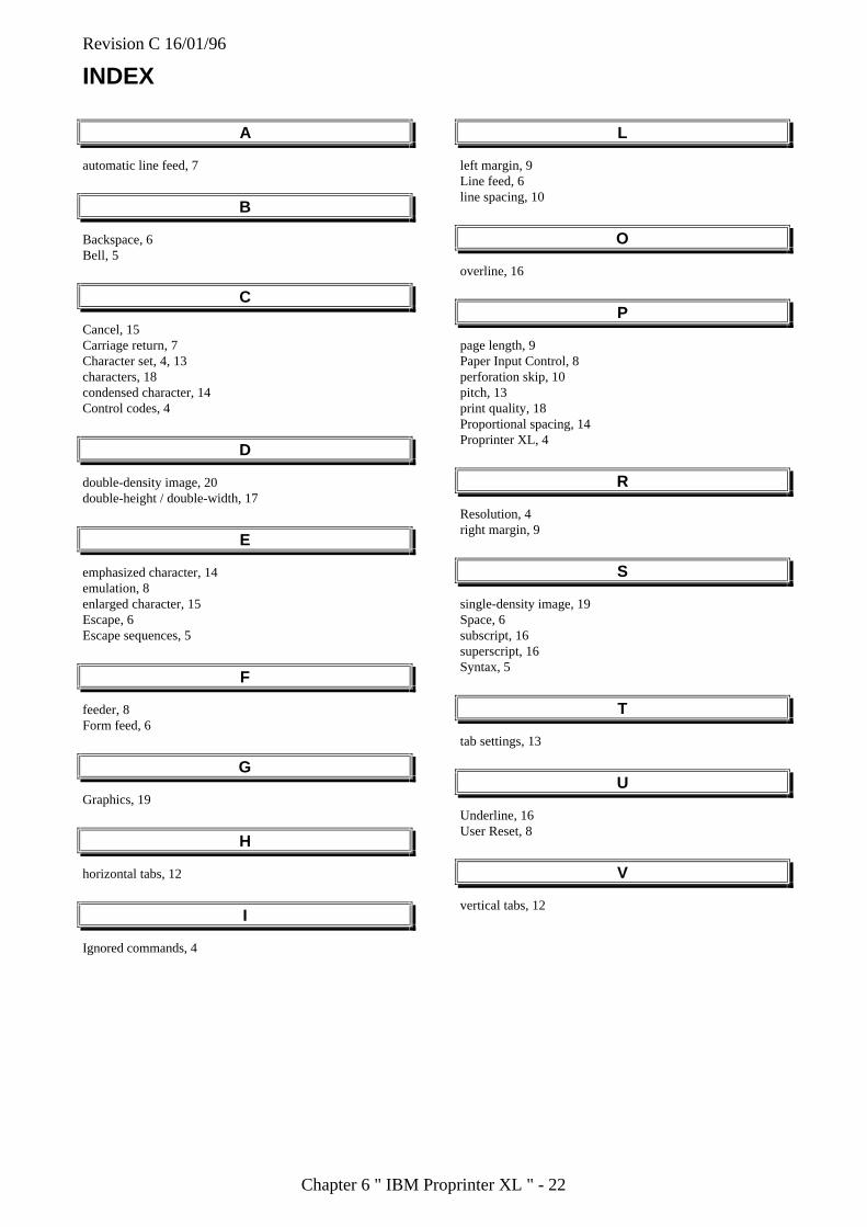
Revision C 16/01/96
Chapter 6 " IBM Proprinter XL " - 22
INDEX
A
automatic line feed, 7
B
Backspace, 6Bell, 5
C
Cancel, 15Carriage return, 7Character set, 4, 13characters, 18condensed character, 14Control codes, 4
D
double-density image, 20double-height / double-width, 17
E
emphasized character, 14emulation, 8enlarged character, 15Escape, 6Escape sequences, 5
F
feeder, 8Form feed, 6
G
Graphics, 19
H
horizontal tabs, 12
I
Ignored commands, 4
L
left margin, 9Line feed, 6line spacing, 10
O
overline, 16
P
page length, 9Paper Input Control, 8perforation skip, 10pitch, 13print quality, 18Proportional spacing, 14Proprinter XL, 4
R
Resolution, 4right margin, 9
S
single-density image, 19Space, 6subscript, 16superscript, 16Syntax, 5
T
tab settings, 13
U
Underline, 16User Reset, 8
V
vertical tabs, 12

Revision C 16/01/96
Chapter 7 "Bar Codes Control" - 1
Chapter 7
Bar Code Control
Revision C 16/01/96
Chapter 7 "Bar Codes Control" - 2
Bar Code Control
The printer can print bar codes in the HP LaserJet 4, Diablo, EPSON FX-850, and IBM ProprinterXL emulation modes.
PRINT BAR CODES OR EXPANDED CHARACTERS
ESC i n ... n \ (27)(105)n ... n (92) <1Bh><69h>n ... n <5Ch>
Creates bar codes or expanded characters according to the segment of parameters “n ... n”. Forfurther information about the parameters, see the following “Definition of Parameters.” Thiscommand must end with the “ \ ” code (5CH).
DEFINITION OF PARAMETERS
This bar code command can have the following parameters in the parameter segment (n ... n).Parameters are effective only within the single command sequence using the syntax ESC in ... n \. They do not take effect in any subsequent bar code commands. If any parameters are notspecified, they take the default settings. The last parameter must be the bar code data startidentifier (“b” or “B”) or the expanded character data start identifier (“l” or “L”). Otherparameters can be specified in any sequence. The prefix of each parameter can be either a lower-case or upper-case character, - for example, “t0” or “T0”, “s3” or “S3”, etc.
(1) Bar Code Mode
n = “t0” or “T0” CODE 39 (default)n = “t1” or “T1” Interleaved 2 of 5n = “t3” or “T3” FIM (US-Post Net)n = “t4” or “T4” Post Net (US-Post Net)n = “t5” or “T5” EAN 8, EAN 13, or UPC An = “t6” or “T6” UPC En = “t9” or “T9” Codabarn = “t12” or “T12” Code 128 set An = “t13” or “T13” Code 128 set Bn = “t14” or “T14” Code 128 set Cn = “t130” or “T130” ISBN (EAN)n = “t131” or “T131” ISBN (UPC-E)n = "t132" or "T132" EAN 128 set An = "t133" or "T133" EAN 128 set Bn = "t134" or "T134" EAN 128 set C
This parameter selects the bar code mode as above. When n is “t5” or “T5”, the bar codemode (EAN 8, EAN 13, or UPC A) varies according to the number of characters in the data.
Revision C 16/01/96
Chapter 7 "Bar Codes Control" - 3
(2) Bar Code Style, Expanded Character shading, Line Block Drawing & BoxDrawing Shading
� Bar Code Style
n = “s0” or “S0” 3 : 1 (default)n = “s1” or “S1” 2 : 1n = “s3” or “S3” 2.5 : 1
This parameter selects the bar code style as above. When the EAN 8, EAN 13, or UPC-Abar code mode is selected, this bar code style parameter is ignored.
� Expanded Character shading
“S” 0 = White1 = Black2 = Vertical stripes3 = Horizontal stripes4 = Cross hatch
eg. “S” n1 n2n1 = Background fill patternn2 = Foreground fill pattern
If “S” is followed by only one parameter, the parameter is a foreground fill pattern.
� Line Block Drawing & Box Drawing Shading
“S” 1 = Black2 = Vertical stripes3 = Horizontal stripes4 = Cross hatch
(3) Bar Code Scaling (Width only)
n = “mnnn” or “Mnnn” (nnn = 0 ~ 32767)
This parameter specifies the bar code scaling of barcord width. The unit of "nnn" is %. Thedefault value is m100 (100%).
(4) Bar Code Human Readable Line On or Off
n = “r0” or “R0” Human readable line OFFn = “r1” or “R1” Human readable line ON
Default: Human readable line ON, when the following barcode types are selected.(1) “T5” or “t5”(2) “T6” or “t6”(3) “T130” or “t130”(4) “T131” or “t131”
Default: Human readable line OFFAll others
This parameter specifies whether or not the printer prints the human readable line below thebar code. Human readable characters are always printed with OCR-B font of 10 pitch, and

Revision C 16/01/96
Chapter 7 "Bar Codes Control" - 4
all the current character style enhancements are masked. Note that the default setting issubject to the bar code mode selected by “t” or “T”.
(5) Quiet Zone
n = “onnn” or “Onnn” (nnn = 0 ~ 32767)
Quiet Zone is the space on both side of the bar codes. Its width can be specified using theunits which are set by the "u" or "U" parameter. ( For the description of "u" or "U"parameter, see the next part.) The default setting of Quiet Zone width is 1 inch.
(6) Bar Code, Expanded Character Unit, Line Block Drawing & Box Drawing Units
n = “u0” or “U0” Millimeters (default)n = “u1” or “U1” 1/10”n = “u2” or “U2” 1/100”n = “u3” or “U3” 1/12”n = “u4” or “U4” 1/120”n = “u5” or “U5” 1/10 Millimetersn = “u6” or “U6” 1/300”n = “u7” or “U7” 1/720”
This parameter specifies the measurement units of X-axis offset, Y-axis offset, and bar codeheight.
(7) Bar Code, Expanded Character, Line, Block Drawing & Box Drawing Offset inX-axis
n = “xnnn” or “Xnnn”
This parameter specifies the offset from the current print position in the “u”- or “U”-specifiedunit.
(8) Bar Code & Expanded Character Offset in Y-axis
n = “ynnn” or “Ynnn”
This parameter specifies the downward offset from the current print position in the “u”- or“U”-specified unit.
(9) Bar Code, Expanded Character, Line, Block Drawing & Box Drawing Height
n = “hnnn”, “Hnnn”, “dnnn”, or “Dnnn”
Default heights
(1) EAN13, EAN8, UPC-A, ISBN (EAN13, EAN8, UPC-A),ISBN (UPC-E): 22 mm
(2) UPC-E: 18 mm(3) Others: 12 mm
Expanded characters ➝ 2.2 mm (default)Line Block Drawing & Box Drawing ➝ 1 dot

Revision C 16/01/96
Chapter 7 "Bar Codes Control" - 5
This parameter specifies the height of bar codes or expanded characters as above. It can takethe prefix “h”, “H”, “d”, or “D”. The height is specified in the “u”- or “U”-specified unit.Note that the default setting of the bar code height (12 mm, 18 mm or 22 mm) is subject to thebar code mode selected by “t” or “T”.
(10) Expanded Character, Line Block Drawing & Box Drawing Width
n = “wnnn” or “Wnnn”
Default widthsExpanded character ➝ 1.2 mmLine Block Drawing & Box Drawing ➝ 1 dot
This parameter specifies the width of expanded characters in the selected units as above.
(11) Expanded Character Rotation
n = “a0” or “A0” Upright (default)n = “a1” or “A1” Rotated 90 degrees clockwisen = “a2” or “A2” Upside down, rotated 180 degrees clockwisen = “a3” or “A3” Rotated 270 degrees clockwise
(12) Bar Code Data Start
n = “b” or “B”
� Data that follows “b” or “B” is read in as bar code data. Bar code data must end withthe “ \ ” code (5CH), which also terminates this command. The acceptable bar codedata is subject to the bar code mode selected by “t” or “T” as listed below.
� When the CODE 39 is selected with the parameter “t0” or “T0”:
Forty three characters “0” to “9”, “A” to “Z”, “–”, “ . ”, “ (space)”, “$”, “ / ”, “+”,and “%” can be accepted as bar code data. Other characters cause data error. Thenumber of characters for bar codes is not limited. The bar code data automaticallystarts and ends with an asterisk “ * ” (start character and stop character). If thereceived data has an asterisk “ * ” at its beginning or end, the asterisk is regarded as astart character or stop character. When you put "?" on the end of the data, a check digitis automatically added.
� When the Interleaved 2 of 5 is selected with the parameter “t1” or “T1”:
Ten numerical characters “0” to “9” can be accepted as bar code data. Othercharacters cause data error. The number of characters for bar codes is not limited.Since this mode of bar codes require even characters, if the bar code data has oddcharacters, the zero character “0” is automatically added to the end of the bar codedata. When you put "?" on the end of the data, a check digit is automatically added.
� When the FIM (US-Post Net) is selected with the parameter “t3” or “T3”:
Characters “A” to “D” are valid and 1 digit of data can be printed. Uppercase andlowercase alphabet characters can be accepted.
� When the Post Net (US-Post Net) is selected with the parameter “t4” or “T4”:
Revision C 16/01/96
Chapter 7 "Bar Codes Control" - 6
Characters “0” to “9” can be data and it must be terminated by a check digit. “?” canbe used in place of a check digit.
� When the EAN 8, EAN 13, or UPC A is selected with the parameter “t5” or “T5”:
Ten numerical characters “0” to “9” can be accepted as bar code data. The number ofcharacters for bar codes is limited as follows.
EAN 8: Total 8 digits (7 digits + 1 check digit)EAN 13: Total 13 digits (12 digits + 1 check digit)UPC A: Total 12 digits (11 digits + 1 check digit)
Any number of characters other than above causes a data error and the bar code data isprinted as normal print data. If the check digit is incorrect, the printer calculates it andreplaces it with the correct check digit so that the correct bar code data will be printed.When the EAN13 is selected, adding “+” and a 2-or 5-digit number after the data willcreate the add-on code.
� When UPC-E is selected with the parameter “t6” or “T6”:
The numerical characters “0” to “9” can be accepted as bar code data.
8 digits Standard format. The first character must be “0” and the data must beterminated by a check digit.
Total 8 digits = "0" + 6 digits + 1 check digit
6 digits The first character "0" and the last check digit are removed from the 8 digitdata.
*1: For 8 digits, “?” can be used in place of a check digit.*2: Adding “+” and 2- or 5-digit number after the data creates an add-on code
for all 6 and 8 digit formats.
� When Codabar is selected with the parameter “t9” or “T9”:
Characters “0” to “9”, “–”, “ . ”, “$”, “/”, “+”, “ : ” can be printed. Characters “A” to“D” can be printed as a start-stop code, which can be uppercase or lowercase. If thereis no start-stop code, an error will occur. The check digit cannot be added and “?”causes an error.
� When Code 128 Set A, Set B, or Set C is selected with the parameter “t12” or “12,”“t13” or “T13,” or “t14” or “T14” respectively:
Code sets A, B and C are individually selectable. Set A encodes characters in the rangeHex 00 to 5F. Set B encodes characters in the range Hex 20 to 7F. Set C encodesnumeric pairs in the range 00 to 99.
- Switching is allowed between the code sets by sending %A, %B, or %C.- FNC 1, 2, 3, and 4 are produced with %1, %2, %3, and %4.- The SHIFT code, %S, allows temporary switching (for 1 character only) between
set A and set B and vice versa.- To print the “%” character, it must be sent twice.
� When ISBN (EAN) is selected with the parameter “t130” or “T130”:
The rules are the same as for “t5” or “T5”
� When the ISBN (UPC-E) is selected with the parameter “t131” or “T131”:
The rules are the same as for “t6” or “T6”
Revision C 16/01/96
Chapter 7 "Bar Codes Control" - 7
• When EAN 128 set A, set B or set C is selected with the parameter "t132" or "T132,""t133" or "T133" or "t134" or "T134" respectively:
Same relues apply as for "t12" or "T12," "t13" or "T13", or "t14" or "T14."
(13) Box Drawing
ESC i ... E (or e)
“E” or “e” is a terminator.
(14) Line Block Drawing
ESC i ... V (or v)
“V” or “v” is a terminator.
(15) Expanded Character Data Start
n = “l” or “L”
Data that follows “l” or “L” is read in as expanded character data (or labeling data).Expanded character data must end with the “ \ ” code (5CH), which also terminates thiscommand. To print the '\' character, you must input '\\'.
EXAMPLE PROGRAM LISTINGS
10 ' Barcode20 WIDTH "LPT1:", 25530 ' CODE 3940 LPRINT CHR$(27); "it0r1s0x00y00b123456\";50 'INTER LEAVED60 LPRINT CHR$(27); "it1r1s0x70y00b123456\";70 ' EAN-1380 LPRINT CHR$(27); "it5r1s0x00y020b123456789012?\";90 LPRINT CHR$(27); "it5r1s0x70y020b123456789012?+12345\";100 ' UPC-A110 LPRINT CHR$(27); "it5r1s0x00y050b12345678901?\";120 LPRINT CHR$(27); "it5r1s0x70y050b12345678901?+12345\";130 ' EAN-8140 LPRINT CHR$(27); "it5r1s0x00y080b1234567?\";150 LPRINT CHR$(27); "it5r1s0x00y080b1234567?+12345\";160 ' UPC-E170 LPRINT CHR$(27); "it6r1s0x00y110b007834000091\";180 LPRINT CHR$(27); "it6r1s0x70y110b007834000091+12344\";190 ' CODABAR195 LPRINT CHR$(27); "it9r1s0x00y140bA123456A\";210 ' POST NET220 LPRINT CHR$(27); "it4r1x95y140b1234567?\";230 ' FIM240 LPRINT CHR$(27); "iT3R1x70Y140BA\";250 ' ISBN260 LPRINT CHR$(27); "it130r1s0x00y170b123456789012?+12345\";270 LPRINT CHR$(27); "it130r1s0x70y170b12345678901?+12345\";
Revision C 16/01/96
Chapter 7 "Bar Codes Control" - 8
280 LPRINT CHR$(27); "it130r1s0x00y200b1234567?+12345\";300 ' LABEL PRINT310 LPRINT CHR$(27); "ih10w10x25y2301Sample\";320 LPRINT CHR$(27); "ix90y230s4h10w10f2g2e";330 LPRINT CHR$(27); "ix105y230s4h10w10v";400 LPRINT CHR$(&HC);
< Sample 19 >
Revision C 16/01/96
Chapter 8 "HP-GL2" 1
CHAPTER 8HP-GL/2 Graphics
Language
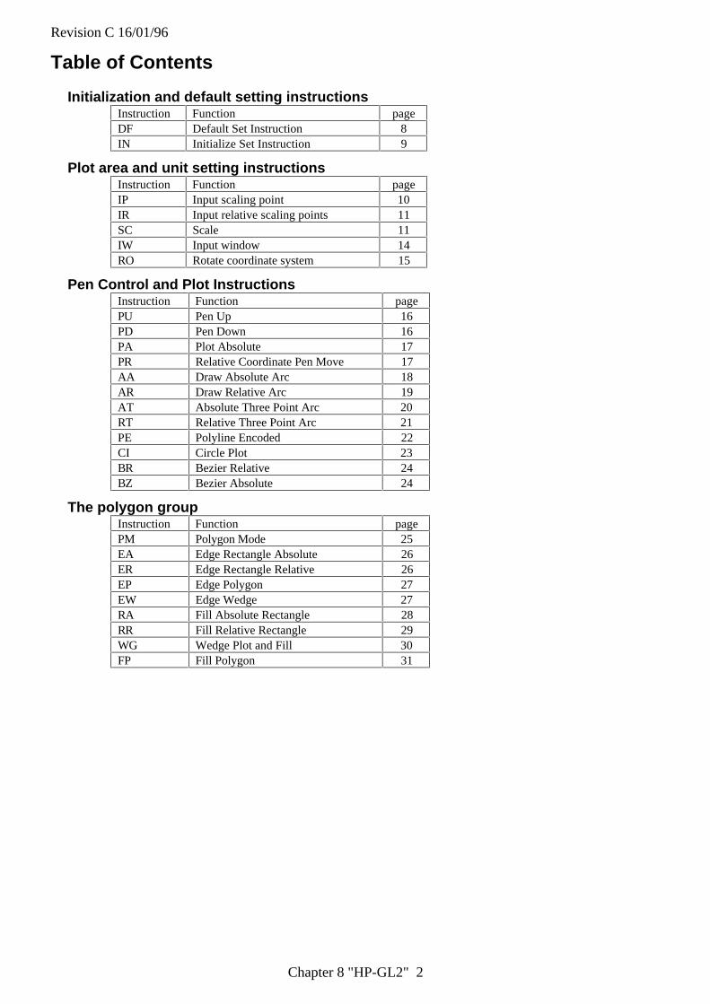
Revision C 16/01/96
Chapter 8 "HP-GL2" 2
Table of Contents
Initialization and default setting instructionsInstruction Function pageDF Default Set Instruction 8IN Initialize Set Instruction 9
Plot area and unit setting instructionsInstruction Function pageIP Input scaling point 10IR Input relative scaling points 11SC Scale 11IW Input window 14RO Rotate coordinate system 15
Pen Control and Plot InstructionsInstruction Function pagePU Pen Up 16PD Pen Down 16PA Plot Absolute 17PR Relative Coordinate Pen Move 17AA Draw Absolute Arc 18AR Draw Relative Arc 19AT Absolute Three Point Arc 20RT Relative Three Point Arc 21PE Polyline Encoded 22CI Circle Plot 23BR Bezier Relative 24BZ Bezier Absolute 24
The polygon groupInstruction Function pagePM Polygon Mode 25EA Edge Rectangle Absolute 26ER Edge Rectangle Relative 26EP Edge Polygon 27EW Edge Wedge 27RA Fill Absolute Rectangle 28RR Fill Relative Rectangle 29WG Wedge Plot and Fill 30FP Fill Polygon 31
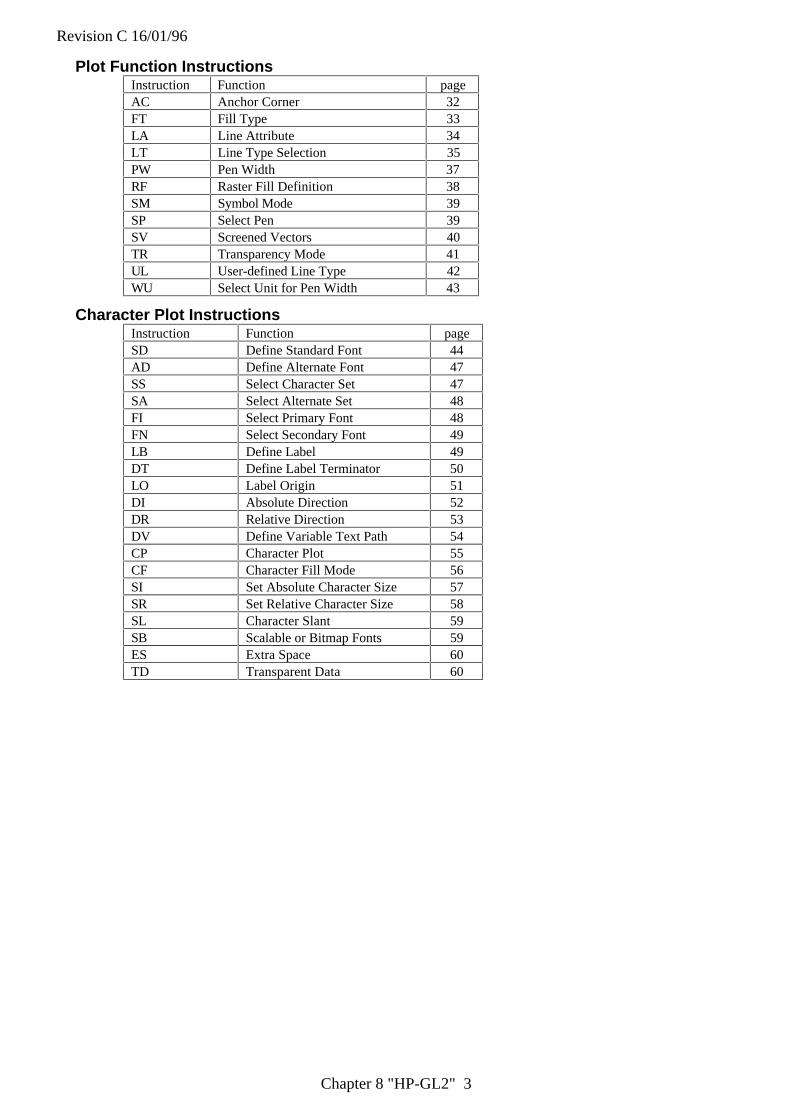
Revision C 16/01/96
Chapter 8 "HP-GL2" 3
Plot Function InstructionsInstruction Function pageAC Anchor Corner 32FT Fill Type 33LA Line Attribute 34LT Line Type Selection 35PW Pen Width 37RF Raster Fill Definition 38SM Symbol Mode 39SP Select Pen 39SV Screened Vectors 40TR Transparency Mode 41UL User-defined Line Type 42WU Select Unit for Pen Width 43
Character Plot InstructionsInstruction Function pageSD Define Standard Font 44AD Define Alternate Font 47SS Select Character Set 47SA Select Alternate Set 48FI Select Primary Font 48FN Select Secondary Font 49LB Define Label 49DT Define Label Terminator 50LO Label Origin 51DI Absolute Direction 52DR Relative Direction 53DV Define Variable Text Path 54CP Character Plot 55CF Character Fill Mode 56SI Set Absolute Character Size 57SR Set Relative Character Size 58SL Character Slant 59SB Scalable or Bitmap Fonts 59ES Extra Space 60TD Transparent Data 60
Revision C 16/01/96
Chapter 8 "HP-GL2" 4
1. IntroductionThis HL-10h/1260/660 printer can be used in HP-GL/2 graphics mode to produce vector graphics outputusing the commands of the HP-GL/2 graphics language or to print out existing HP-GL/2 format images.HP-GL/2 is a part of the PCL emulation, which includes graphics command.
The Default plotting measurement unit in the HP-GL/2 graphics mode is 1/1016" ( 0.025 mm).
2. TerminologyPicture Frame
The printer frame is the rectangular area of the page on which graphic output can be printed. This is basedon the logical page defined for the selected paper size.
Anchor pointThe anchor point of the picture frame is the top left hand corner of the frame. This can be moved on thepage using PCL language page control commands.
Graphics windowThe graphics window is the rectangular area of the page on which you can generate graphic output usingHP-GL/2 commands. Initially the graphics window is the same as the picture frame but may be alteredusing the HP-GL/2 IW command.
Hard clip limitsHard clip limits are the physical restrictions which define where printed output can appear on a page.
Soft clip limitsSoft clip limits are the user-defined restrictions which define where printed output can appear on a page.
Graphics unitsThe initial coordinate system employs units of 1/1016" in both the x- and y-axes.
User unitsThe HP-GL/2 graphics language uses a coordinate system. You can impose your own x- and y-scale unitson this system using the SC command.
Current unitsThe units in use at a given time are called the current units. Current units are either user units or graphicsunits, depending on whether scaling has been turned on or not. The SC command is used to turn scalingon, that is, to make user units the current units.
PensBy convention, certain HP-GL/2 graphics language commands are thought of as using a pen, which can beeither up or down. To produce plotted output the pen must be down. To move to a location on the pagewithout producing output the pen must be in the up position. Some HP-GL/2 commands require you tospecify the pen position before you use them: others have implied pen positions built into them, so thatyou do not need to specify "Pen up" or "Pen down".
Absolute and relative plottingDrawing commands are of two distinct types: absolute commands, in which the coordinates specified arethe absolute user or graphics coordinates, and relative commands, whose coordinates are relative to thecoordinate position at which the previous graphics command terminated.
FillsYou can fill in the shapes you have drawn with the plotting commands by using the fill commands. Anumber of different shading options are available.
Revision C 16/01/96
Chapter 8 "HP-GL2" 5
3. Command syntax
An HP-GL and HP-GL/2 command can consist of up to four items: a mnemonic, a parameter field, aseparator and a terminator.
MnemonicThe two-letter mnemonic is the name of the command and should help remind you of its function.
ParametersSome commands have parameters following the instruction mnemonic. Multiple parameters must haveseparators between them. Parameters are shown in italics. Optional parameters are surrounded by squarebrackets. Parameters that can be repeated are followed by "...".
• Integer - integers between -230 and 230 - 1. Real numbers specified for a parameter that should be an integerare rounded to the nearest integer.
• Clamped integer - integers between -32768 and 32767. Parameters outside this range are converted(clamped) to the nearest integer within the range, for example 40,000 will be clamped to 32767. Non-integers are converted to the nearest integer.
• Real number - real numbers whose integer part is in the range -230 to 230 - 1. Accuracy to at least 6significant digits is guaranteed. If a number outside the range is specified the entire command is ignored.The decimal point can be omitted when the number has no fractional part.
• Clamped real number - real numbers whose integer part is in the range -32768 to 32767. Parametersoutside this range are converted (clamped) to the nearest real number within the range. The decimal pointcan be omitted when the number has no fractional part.
Text parameters are referred to as labels and can consist of any sequence of characters.
SeparatorsIf an HP-GL/2 instruction accepts more than one parameter, you must put spaces or a comma between theparameters to separate them.
TerminatorMost commands are terminated implicitly by the first letter of the next instruction mnemonic. A semi-colonmay be used to explicitly terminate a command. However, the final command issued before quitting HP-GL/2 mode must be terminated with a semi-colon. Since a terminator is almost always optional it is shownsurrounded by square brackets.

Revision C 16/01/96
Chapter 8 "HP-GL2" 6
4. The HP-GL graphics windowUnits
When you first enter graphics mode, the prevailing coordinate system has its origin in the bottom left handcorner of the graphics window and has x- and y-units of 1/1016". Using the SC command you can divide theaxes into more convenient units. The size of the graphics window remains unaltered.
The scaling points P1 and P2Many instructions use two reference scaling points, P1 and P2. Initially these are in the bottom left and topright hand corners of the graphics window respectively. You can alter the position of these points relative tothe graphics window, or relative to one another, using the IP or IR commands.
ScalingYou can easily scale images up or down by increasing or decreasing the distance between P1 and P2. Youcan do this both with existing images that are to be imported and with images that are generated by a stringof HP-GL and HP-GL/2 commands - identical commands can be used to create the same image in differentsizes.
TransformationYou can transform images horizontally or vertically by changing the relative positions of P1 and P2. Youcan do this both with existing images that are to be imported and with images that are generated by a stringof HP-GL/2 commands.
5. Preparing to print graphic imagesSetting up the graphics window
Before entering HP-GL/2 mode you will probably want to set the dimensions and position of the PCL pictureframe and hence the graphics window. (Remember that when you enter HP-GL/2 mode they are initially thesame). To do this you will need to send some preparatory PCL commands while in LaserJet mode. Use theEsc*c0T command to position the picture frame and the Esc*c#X and Esc*c#Y commands to determine it'shorizontal and vertical dimensions respectively. These commands are described fully in the sub-sectionVector Graphics in the LaserJet section of this manual. ( Section 2 )
If you do not specify a position and dimensions for the picture frame, the default picture frame is used. Thisis described in the sub-section The Page in the LaserJet section of this manual.
Using Existing image plots.If you are importing an existing HP-GL/2 plot you can easily determine the size and position on the page ofthe resulting printed graphic. Images are automatically scaled and fitted to the picture frame ( the HP-GL/2graphics window ) in either of the following two cases.
1) If you use the Esc*c#K and Esc*c#L PCL commands to specify the width and height of the originalplot before entering HP-GL/2 mode. These commands are explained in the sub-section VectorGraphics in the LaserJet section of this manual. Only use these commands if you are importing anexisting plot.
2) If the imported image code is page-size independent.
An image is page-size independent if it's HP-GL/2 code satisfies the following conditions.
� User units are used exclusively, that is, an SC command is used before any drawing commands areissued. Note in particular that if the graphics window is changed from the default using the IWcommand, it must be specified in user units.
� No absolute units are used or implied, that is, drawing commands use relative movement only andcharacter size, pattern length and pen width are always specified as relative measurements.Commands like IP and PA, which imply the use of absolute units even if none are explicitly supplied,should not be used at all.
Revision C 16/01/96
Chapter 8 "HP-GL2" 7
If you import an image without fulfilling these two criteria, that is, the image is not page size independentand you do not specify its horizontal and vertical plot sizes, the plot will be drawn actual size. Any part ofthe plot that falls outside the effective window will not appear on the printed page.
Printing an imageWhen you have carried out any necessary preliminary steps that your particular application requires, asdescribed in the preceding sections, enter HP-GL/2 mode using the Esc%#B command and send thesequence of HP-GL/2 commands to generate the image.
Entering HP-GL/2 modeTo enter graphics mode from PCL printer control language use the Esc%#B command. Set # to 0 if youwant the pen to start from the previous HP-GL/2 pen position. Set # to 1 if you want to the pen to start fromthe current PCL cursor position. You must specify either one setting or the other.
Quitting HP-GL/2 modeTo quit graphics mode use the Esc%#A command. Set # to 0 if you want to place the cursor at the previousPCL cursor position. This is also the default setting. Set # to 1 if you want to place the cursor at the currentHP-GL/2 pen position.
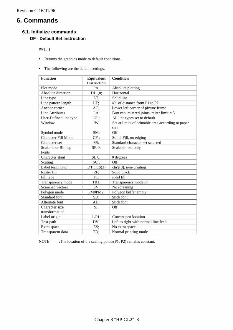
Revision C 16/01/96
Chapter 8 "HP-GL2" 8
6. Commands
6.1. Initialize commandsDF - Default Set Instruction
DF[;]
• Returns the graphics mode to default conditions.
• The following are the default settings.
Function EquivalentInstruction
Condition
Plot mode PA; Absolute plottingAbsolute direction DI 1,0; HorizontalLine type LT; Solid lineLine pattern length LT; 4% of distance from P1 to P2Anchor corner AC; Lower left corner of picture frameLine Attributes LA; Butt cap, mitered joints, miter limit = 5User-Defined line type UL; All line types set to defaultWindow IW; Set at limits of printable area according to paper
sizeSymbol mode SM; OffCharacter Fill Mode CF ; Solid, Fill, no edgingCharacter set SS; Standard character set selectedScalable or BitmapFonts
SB 0; Scalable font only
Character slant SL 0; 0 degreesScaling SC ; OffLabel terminator DT chr$(3) chr$(3), non-printingRaster fill RF; Solid blackFill type FT; solid fillTransparency mode TR1; Transparency mode onScreened vectors SV; No screeningPolygon mode PM0PM2; Polygon buffer emptyStandard font SD; Stick fontAlternate font AD; Stick fontCharacter sizetransformation
SI; Off
Label origin LO1; Current pen locationText path DV; Left to right with normal line feedExtra space ES; No extra spaceTransparent data TD; Normal printing mode
NOTE :The location of the scaling points(P1, P2) remains constant.
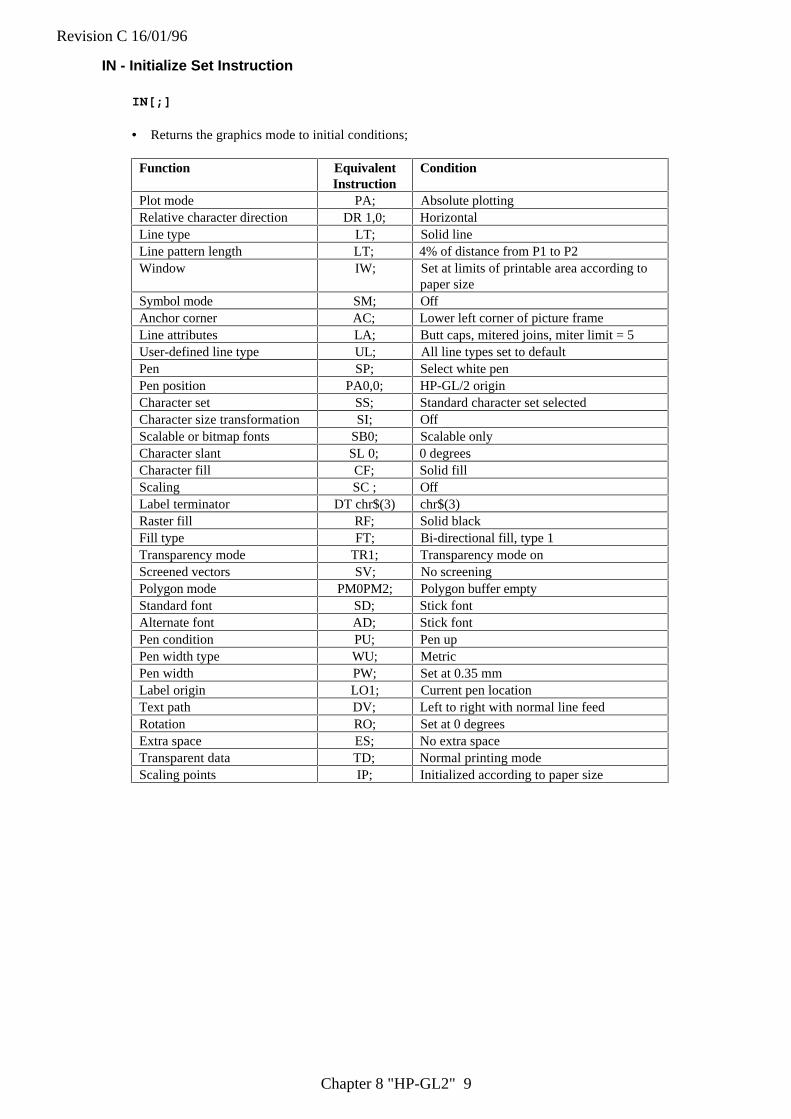
Revision C 16/01/96
Chapter 8 "HP-GL2" 9
IN - Initialize Set Instruction
IN[;]
• Returns the graphics mode to initial conditions;
Function EquivalentInstruction
Condition
Plot mode PA; Absolute plottingRelative character direction DR 1,0; HorizontalLine type LT; Solid lineLine pattern length LT; 4% of distance from P1 to P2Window IW; Set at limits of printable area according to
paper sizeSymbol mode SM; OffAnchor corner AC; Lower left corner of picture frameLine attributes LA; Butt caps, mitered joins, miter limit = 5User-defined line type UL; All line types set to defaultPen SP; Select white penPen position PA0,0; HP-GL/2 originCharacter set SS; Standard character set selectedCharacter size transformation SI; OffScalable or bitmap fonts SB0; Scalable onlyCharacter slant SL 0; 0 degreesCharacter fill CF; Solid fillScaling SC ; OffLabel terminator DT chr$(3) chr$(3)Raster fill RF; Solid blackFill type FT; Bi-directional fill, type 1Transparency mode TR1; Transparency mode onScreened vectors SV; No screeningPolygon mode PM0PM2; Polygon buffer emptyStandard font SD; Stick fontAlternate font AD; Stick fontPen condition PU; Pen upPen width type WU; MetricPen width PW; Set at 0.35 mmLabel origin LO1; Current pen locationText path DV; Left to right with normal line feedRotation RO; Set at 0 degreesExtra space ES; No extra spaceTransparent data TD; Normal printing modeScaling points IP; Initialized according to paper size
Revision C 16/01/96
Chapter 8 "HP-GL2" 10
6.2. Plot area and unit setting instructions
Instruction FunctionIP Scaling pointIR Input relative scaling pointsSC ScaleIW Input windowRO Rotate coordinate system
IP - Input Scaling Point
IP [ P1 X, P1 Y [,P2 X, P2 Y]] [;]
P1X ; X coordinate of P1 P1Y ; Y coordinate of P1P2X ; X coordinate of P2 P2Y ; Y coordinate of P2
• The coordinates used are absolute values in graphics units.
• Sets the location of the scaling points(P1,P2).
• Coordinate values for P1X,P1Y,P2X and P2Y are given as the integer numbers.
• You can set P1 and P2 to be anywhere that the range of allowable coordinates permits. However, only partsof resulting images that lie within the effective window will be printed.
• The default location of P1 is the lower left corner and P2 is the upper right corner of the PCL picture frame.
• Using this instruction without a parameter field initializes the scaling points(P1,P2) to the default location.
• P2X and P2Y may be omitted. (If P2X and P2Y are omitted, P2 is set automatically so as not to alter thedistance between P1 and P2).
• If P2x and P2y are omitted P2 is set to be in the same position relative to P1 that it was before the commandwas invoked.
• The IP command remains in effect until another IP command, an IR command or an IN command is used.
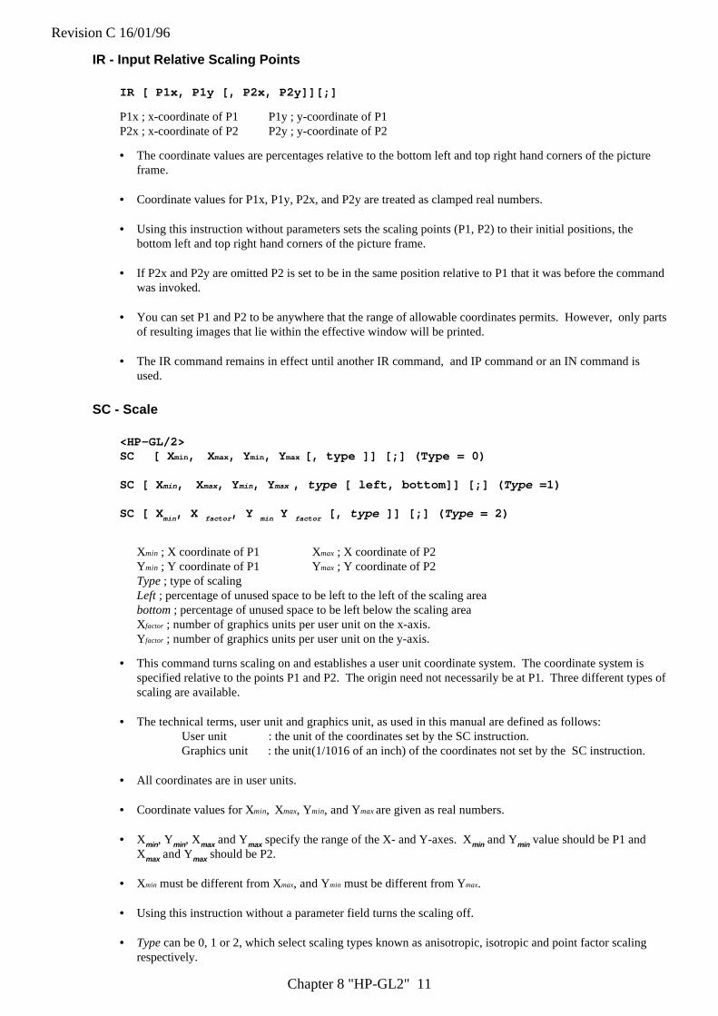
Revision C 16/01/96
Chapter 8 "HP-GL2" 11
IR - Input Relative Scaling Points
IR [ P1x, P1y [, P2x, P2y]][;]
P1x ; x-coordinate of P1 P1y ; y-coordinate of P1P2x ; x-coordinate of P2 P2y ; y-coordinate of P2
• The coordinate values are percentages relative to the bottom left and top right hand corners of the pictureframe.
• Coordinate values for P1x, P1y, P2x, and P2y are treated as clamped real numbers.
• Using this instruction without parameters sets the scaling points (P1, P2) to their initial positions, thebottom left and top right hand corners of the picture frame.
• If P2x and P2y are omitted P2 is set to be in the same position relative to P1 that it was before the commandwas invoked.
• You can set P1 and P2 to be anywhere that the range of allowable coordinates permits. However, only partsof resulting images that lie within the effective window will be printed.
• The IR command remains in effect until another IR command, and IP command or an IN command isused.
SC - Scale
<HP-GL/2>SC [ X min , Xmax, Y min , Y max [, type ]] [;] (Type = 0)
SC [ X min , Xmax, Y min , Y max , type [ left, bottom]] [;] ( Type =1)
SC [ X min , X factor , Y min Y factor [, type ]] [;] ( Type = 2)
Xmin ; X coordinate of P1 Xmax ; X coordinate of P2Ymin ; Y coordinate of P1 Ymax ; Y coordinate of P2Type ; type of scalingLeft ; percentage of unused space to be left to the left of the scaling areabottom ; percentage of unused space to be left below the scaling areaXfactor ; number of graphics units per user unit on the x-axis.Yfactor ; number of graphics units per user unit on the y-axis.
• This command turns scaling on and establishes a user unit coordinate system. The coordinate system isspecified relative to the points P1 and P2. The origin need not necessarily be at P1. Three different types ofscaling are available.
• The technical terms, user unit and graphics unit, as used in this manual are defined as follows:User unit : the unit of the coordinates set by the SC instruction.Graphics unit : the unit(1/1016 of an inch) of the coordinates not set by the SC instruction.
• All coordinates are in user units.
• Coordinate values for Xmin, Xmax, Ymin, and Ymax are given as real numbers.
• Xmin , Ymin , Xmax and Ymax specify the range of the X- and Y-axes. Xmin and Ymin value should be P1 andXmax and Ymax should be P2.
• Xmin must be different from Xmax, and Ymin must be different from Ymax.
• Using this instruction without a parameter field turns the scaling off.
• Type can be 0, 1 or 2, which select scaling types known as anisotropic, isotropic and point factor scalingrespectively.
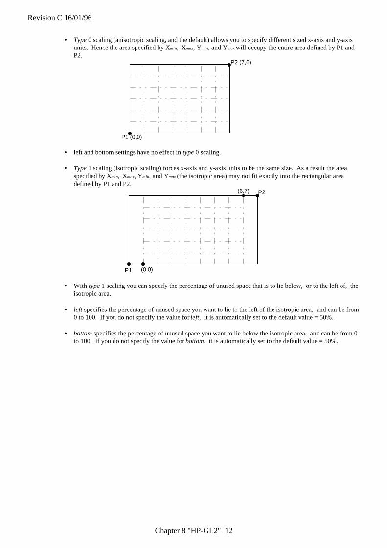
Revision C 16/01/96
Chapter 8 "HP-GL2" 12
• Type 0 scaling (anisotropic scaling, and the default) allows you to specify different sized x-axis and y-axisunits. Hence the area specified by Xmin, Xmax, Ymin, and Ymax will occupy the entire area defined by P1 andP2.
P1 (0,0)
P2 (7,6)
• left and bottom settings have no effect in type 0 scaling.
• Type 1 scaling (isotropic scaling) forces x-axis and y-axis units to be the same size. As a result the areaspecified by Xmin, Xmax, Ymin, and Ymax (the isotropic area) may not fit exactly into the rectangular areadefined by P1 and P2.
P1 (0,0)
(6,7) P2
• With type 1 scaling you can specify the percentage of unused space that is to lie below, or to the left of, theisotropic area.
• left specifies the percentage of unused space you want to lie to the left of the isotropic area, and can be from0 to 100. If you do not specify the value for left, it is automatically set to the default value = 50%.
• bottom specifies the percentage of unused space you want to lie below the isotropic area, and can be from 0to 100. If you do not specify the value for bottom, it is automatically set to the default value = 50%.
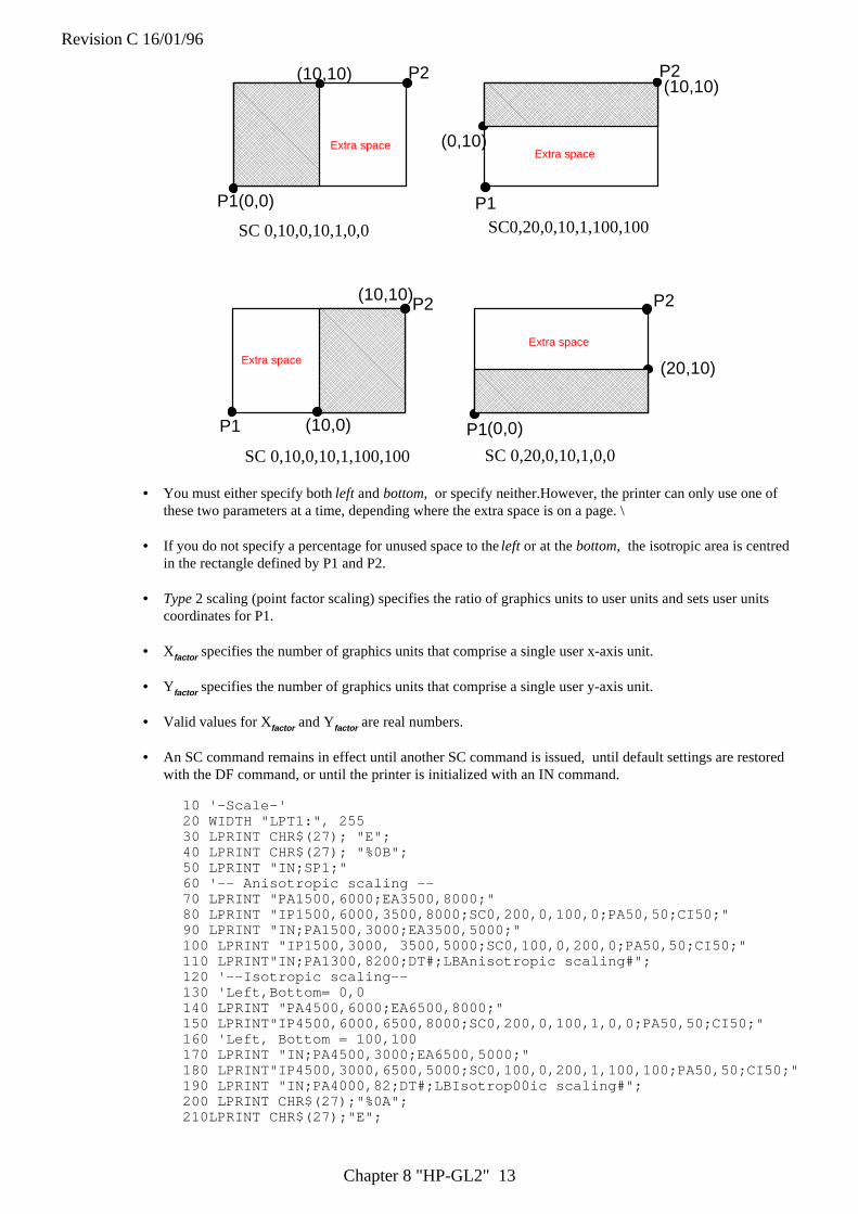
Revision C 16/01/96
Chapter 8 "HP-GL2" 13
P1(0,0)
(10,10) P2 P2
P2P2
P1 P1
P1
(0,10)
(10,10)
(10,0)
(10,10)
(0,0)
(20,10)
SC 0,10,0,10,1,0,0 SC0,20,0,10,1,100,100
SC 0,10,0,10,1,100,100 SC 0,20,0,10,1,0,0
Extra spaceExtra space
Extra space
Extra space
• You must either specify both left and bottom, or specify neither.However, the printer can only use one ofthese two parameters at a time, depending where the extra space is on a page. \
• If you do not specify a percentage for unused space to the left or at the bottom, the isotropic area is centredin the rectangle defined by P1 and P2.
• Type 2 scaling (point factor scaling) specifies the ratio of graphics units to user units and sets user unitscoordinates for P1.
• Xfactor specifies the number of graphics units that comprise a single user x-axis unit.
• Yfactor specifies the number of graphics units that comprise a single user y-axis unit.
• Valid values for Xfactor and Yfactor are real numbers.
• An SC command remains in effect until another SC command is issued, until default settings are restoredwith the DF command, or until the printer is initialized with an IN command.
10 '-Scale-'20 WIDTH "LPT1:", 25530 LPRINT CHR$(27); "E";40 LPRINT CHR$(27); "%0B";50 LPRINT "IN;SP1;"60 '-- Anisotropic scaling --70 LPRINT "PA1500,6000;EA3500,8000;"80 LPRINT "IP1500,6000,3500,8000;SC0,200,0,100,0;PA50,50;CI50;"90 LPRINT "IN;PA1500,3000;EA3500,5000;"100 LPRINT "IP1500,3000, 3500,5000;SC0,100,0,200,0;PA50,50;CI50;"110 LPRINT"IN;PA1300,8200;DT#;LBAnisotropic scaling#";120 '--Isotropic scaling--130 'Left,Bottom= 0,0140 LPRINT "PA4500,6000;EA6500,8000;"150 LPRINT"IP4500,6000,6500,8000;SC0,200,0,100,1,0,0;PA50,50;CI50;"160 'Left, Bottom = 100,100170 LPRINT "IN;PA4500,3000;EA6500,5000;"180 LPRINT"IP4500,3000,6500,5000;SC0,100,0,200,1,100,100;PA50,50;CI50;"190 LPRINT "IN;PA4000,82;DT#;LBIsotrop00ic scaling#";200 LPRINT CHR$(27);"%0A";210LPRINT CHR$(27);"E";
Revision C 16/01/96
Chapter 8 "HP-GL2" 14
220 END
<Sample 21>
Revision C 16/01/96
Chapter 8 "HP-GL2" 15
IW - Window
IW [ X 1, Y 1, X 2, Y 2 ] [;]
X1-Window lower left X coordinate Y1-Window lower left Y coordinateX2-Window upper right X coordinate Y2-Window upper right Y coordinate
• This instruction sets the window inside which drawing can be performed (the soft clip limits).
• Coordinates are specified in current units.
• Using this instruction with no parameters sets the window to be the same as the picture frame.
• You can set the corners of the window to lie outside the picture frame. However, only the portion of theimage which lies within both the picture frame and the window will appear on the page.
• If scaling is turned on with the SC command before the window is defined with the IW command, you canmove the window on the physical page by specifying different locations for P1 and P2 with the IP and IRcommands. The user unit coordinates that bound the window remain the same.
• If an SC command is used after the IW window definition, the window is fixed on the physical page anddoes not move when subsequent IP and IR commands are invoked.
• An IW command remains in effect until another IW command is issued, until default settings are restoredwith the DF command, or until the printer is initialized with an IN command.
10 '--Input Window--20 WIDTH "LPT1:",25530 LPRINT CHR$(27);"E";40 LPRINT CHR$(27);"%0B";50 LPRINT "IN;SP1;";60 LPRINT "SI0.2,0.35,PA2000,3200;;LBTHIS IS AN EXAMPLE OF IW";CHR$(3)70 LPRINT "IW3000,1300,4500,3700;PD2000,1700;LBTHIS IS AN EXAMPLE OFIW";CHR$(3)80 LPRINT "PU3000,1300;PD4500,1300,4500,3700;PD3000,3700,3000,1300;PU;"90 LPRINT CHR$(27);"%0A";100 LPRINT CHR$(27);"E";110 END
<Sample 22>
Revision C 16/01/96
Chapter 8 "HP-GL2" 16
RO - Rotate coordinate system
RO [ q][;]
q : Angle in degrees through which the coordinate system is rotated.
• This instruction is used to rotate the graphics coordinate system anti-clockwise.
• Using this instruction with no parameter sets the rotation of the coordinate system to 0 degrees (defaultvalue).
• The pen position does not change.
• P1 and P2 rotate with the coordinate system and retain the same coordinate values.
• To relocate P1 and P2 at the lower left and upper right hand corners of the picture frame, use the IP; or IR;command.
• If you have previously used an IW command, the window is also rotated. Any part of the window that fallsoutside the hard clip limits will be clipped.
• The command remains in effect until another RO command is used, or until the printer is initialized withthe IN instruction.
• Valid values of q are 0, 90, 180 or 270.
10 '--Rotate Coordinate System--20 WIDTH "LPT1:",25530 LPRINT CHR$(27);"E";40 LPRINT CHR$(27);"%0B";50 LPRINT "IN;SP1;";60 FOR I = 0 TO 270 STEP 9070 LPRINT "RO"; I; "PA1000,2000;PD3000,2000,2000,3000,1000,2000;PU;"80 LPRINT "LB RO ="; I; CHR$(3)90 LPRINT "PA600,1500;LBRotate Coordinate System";CHR$(3)100 NEXT I110 LPRINT CHR$(27);"%0A";120 LPRINT CHR$(27);"E";130 END
<Sample 23>

Revision C 16/01/96
Chapter 8 "HP-GL2" 17
6.3. Pen Control and Plot Instructions
Instruction FunctionPU Pen UpPD Pen DownPA Plot AbsolutePR Relative Coordinate Pen MoveAA Absolute Arc PlotAR Relative Arc PlotAT Absolute Three Point ArcRT Relative Three Point ArcPE Polyline EncodedCI CircleBR Bezier RelativeBZ Bezier Absolute
PU - Pen Up
PU [ X,Y [,...]] [;]
X ; X coordinate of the cursor movement destinationY ; Y coordinate of the cursor movement destination
• X and Y are either relative or absolute, depending on whether a PA or a PR was the last plot commandexecuted. The absolute coordinates are set as default.
• You can specify as many coordinate pairs as you wish. The cursor moves to each point in turn withoutdrawing.
• Using this instruction without a parameter field raises the pen without changing the cursor position.
• Coordinates are specified in the currently selected unit.
• In symbol mode PU draws the specified symbol at each point in the parameter list.
• In polygon mode the specified coordinate pairs are placed in the polygon buffer.
• If an odd number of coordinates are specified, the final, unpaired coordinate is ignored.
PD - Pen Down
PD [ X, Y [,...]] [;]
X ; X coordinate of the cursor movement destinationY ; Y coordinate of the cursor movement destination
• X and Y are either relative or absolute, depending on whether a PA or a PR was the last plot commandexecuted. The absolute coordinates are the default setting.
• You can specify as many coordinate pairs as you wish. The cursor moves to each point in turn, drawinglines on the page.
• Using this instruction without a parameter lowers the pen without changing the cursor position.
• Coordinates are specified in the currently selected unit.
• In symbol mode PD draws the specified symbol at each defined point on the x- and y-axis.
• In polygon mode the specified coordinate pairs are placed in the polygon buffer.
• If an odd number of coordinates are specified, the final, unpaired coordinate is ignored.
Revision C 16/01/96
Chapter 8 "HP-GL2" 18
PA - Plot Absolute
PA [ X, Y [,...]] [;]
X ; X coordinate of the cursor movement destinationY ; Y coordinate of the cursor movement destination
• Coordinates are absolute values in user or current units.
• Whether used with or without parameters the command establishes absolute plotting as the plotting mode.
• The command moves the cursor to the specified coordinates, drawing straight lines, only when the pen isdown.
• In symbol mode PA draws the specified symbol at each point in the parameter list.
• In polygon mode the specified coordinate pairs are placed in the polygon buffer.
• If an odd number of coordinates are specified, the final, unpaired coordinate is ignored.
10 ' -- Plot Absolute --20 WIDTH "LPT1:",25530 LPRINT CHR$(27);"E";40 LPRINT CHR$(27);"%0B";50 LPRINT "IN;SP1;";60 LPRINT "PA2000,6000;PD0,6000,2000,7500,2000,6000;PU2500,6000;";70 LPRINT "PAPD4500,6000,2500,7500,2500,6000;PU10365,500;";80 LPRINT CHR$(27);"%0A";90 LPRINT CHR$(27);"E";100 END
<Sample 24>
PR - Relative Coordinate Pen Move
PR [X, Y [,...]] [;]
X ; X coordinate of the cursor movement destinationY ; Y coordinate of the cursor movement destination
• Coordinates used are relative values in current units.
• Whether used with or without parameters the command establishes relative plotting as the plotting mode.
• The command moves the cursor to the specified coordinates, drawing straight lines, only when the pen isdown.
• You can specify any number of coordinated pairs and plotting is performed in the order the coordinates arespecified.
• In symbol mode PR draws the specified symbol at each point in the parameter list.
• In polygon mode the specified coordinate pairs are placed in the polygon buffer.
• If an odd number of coordinates are specified, the final, unpaired coordinate is ignored.
10 ' - Plot Relative -20 WIDTH "LPT1:", 25520 LPRINT CHR$(27); "E";30 LPRINT CHR$(27); "%0B";40 LPRINT "IN;SP1;"50 LPRINT "PA5000,4500,;PDPR-2000,0,2000,2000,0,-2000;PU500,0;"60 LPRINT "PD2000,0,-2000,2000,0,-2000;PU;"70 LPRINT CHR$(27); "%0A";80 LPRINT CHR$(27); "E";90 END
<Sample 25>
AA - Draw Absolute Arc
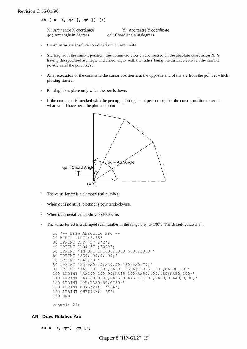
Revision C 16/01/96
Chapter 8 "HP-GL2" 19
AA [ X, Y, qc [, qd ]] [;]
X ; Arc centre X coordinate Y ; Arc centre Y coordinateqc ; Arc angle in degrees qd ; Chord angle in degrees
• Coordinates are absolute coordinates in current units.
• Starting from the current position, this command plots an arc centred on the absolute coordinates X, Yhaving the specified arc angle and chord angle, with the radius being the distance between the currentposition and the point X,Y.
• After execution of the command the cursor position is at the opposite end of the arc from the point at whichplotting started.
• Plotting takes place only when the pen is down.
• If the command is invoked with the pen up, plotting is not performed, but the cursor position moves towhat would have been the plot end point.
(X,Y)
qc = Arc Angleqd = Chord Angle
• The value for qc is a clamped real number.
• When qc is positive, plotting is counterclockwise.
• When qc is negative, plotting is clockwise.
• The value for qd is a clamped real number in the range 0.5° to 180°. The default value is 5°.
10 '-- Draw Absolute Arc --20 WIDTH "LPT1:",25530 LPRINT CHR$(27);"E";40 LPRINT CHR$(27);"%0B";50 LPRINT "IN;SP1;IP1000,1000,6000,6000;"60 LPRINT "SC0,100,0,100;"70 LPRINT "PA0,30;"80 LPRINT "PD;PA0,45;AA0,50,180;PA0,70;"90 LPRINT "AA0,100,900;PA100,55;AA100,50,180;PA100,30;"100 LPRINT "AA100,100,90;PA45,100;AA50,100,180;PA80,100;"110 LPRINT "AA100,0,90;PA55,0;AA50,0,180;PA30,0;AA0,0,90;"120 LPRINT "PU;PA50,50,CI20;"130 LPRINT CHR$(27); "%0A";140 LPRINT CHR$(27); "E";150 END
<Sample 26>
AR - Draw Relative Arc
AR X, Y, qc (, qd)[;]
Revision C 16/01/96
Chapter 8 "HP-GL2" 20
X ; Arc centre X coordinate Y ; Arc centre Y coordinateqc ; Arc angle in degrees qd ; Chord angle in degrees
• Coordinates are relative values in current units.
• Starting from the current cursor position the command plots an arc whose centre is at the relative coordinateposition (X,Y) and which has the specified arc and chord angles. The radius of the arc is the distancebetween the current position and the point (X,Y).
• After execution of the command the cursor position is at the opposite end of the arc from the point at whichplotting started.
• Plotting takes place only when the pen is down.
• If the command is invoked with the pen up, plotting is not performed, but the cursor position moves towhat would have been the plot end point.
• The value for qc is a clamped real number.
• When qc is positive, plotting is counterclockwise.
• When qc is negative, plotting is clockwise.
• The value for qd is a clamped real number in the range 0.5° to 180°. The default value is 5°.
10 '--Draw Relative Arc --20 WIDTH "LPT1:", 25530 LPRINT CHR$(27); "E";40 LPRINT CHR$(27); "%0B";50 LPRINT "IN;SP1;IP1000,1000,6000,6000;"60 LPRINT "SC-100,100,-100,100;"70 LPRINT
"PA-100,70;PD;PR30,0;AR0,-70,-90,15;AR70,0,90;PR60,0;PU;"80 LPRINT CHR$(27); "%0A";90 LPRINT CHR$(27); "E";100 END
<Sample 27>
Revision C 16/01/96
Chapter 8 "HP-GL2" 21
AT - Absolute Arc Three Point
AT X 1, Y 1, X 2, Y 2 [, qd] [;]
X1 ; x-coordinate of intermediate point Y2 ; y-coordinate of intermediate pointX2 ; x-coordinate of end point y2 ; y-coordinate of end pointqd ; the chord angle used to draw the arc
• All coordinates are absolute and in current units.
• The command draws an arc from the current position, through the specified intermediate position andfinishing at the specified end position.
• After completion of the command the current cursor position is at the end of the arc.
• An arc can be drawn clockwise or anti-clockwise.
• If the current scaling mode is not isotropic, the arc may be elliptical rather than circular.
• The chord angle must be in the range 0.5° to 180°.
• The default chord angle is 5°.
10 '--Absolute Arc Three Point--20 WIDTH "LPT1:",25530 LPRINT CHR$(27);"E";40 LPRINT CHR$(27);"%0B";50 LPRINT "IN;SP1;";60 LPRINT "PA1000,100;PD2500,100;"70 LPRINT "PU650,1150;PD1000,1150;"80 LPRINT "PU650,450;PD1000,450;"90 LPRINT "PU1000,100;PD1000,1500,2500,1500;"100 LPRINT "AT3200,800,2500,1500;"110 LPRINT "PU3200,900;PD;"120 LPRINT "AT3300,800,3200,700;"130 LPRINT "PU3300,800;PD3500,800;"140 LPRINT CHR$(27);"%0A";150 LPRINT CHR&(27);"E";160 END
<Sample 28>
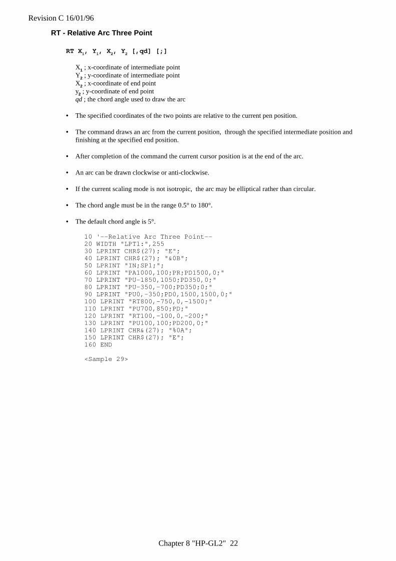
Revision C 16/01/96
Chapter 8 "HP-GL2" 22
RT - Relative Arc Three Point
RT X 1, Y 1, X 2, Y 2 [,qd] [;]
X1 ; x-coordinate of intermediate pointY2 ; y-coordinate of intermediate pointX2 ; x-coordinate of end pointy2 ; y-coordinate of end pointqd ; the chord angle used to draw the arc
• The specified coordinates of the two points are relative to the current pen position.
• The command draws an arc from the current position, through the specified intermediate position andfinishing at the specified end position.
• After completion of the command the current cursor position is at the end of the arc.
• An arc can be drawn clockwise or anti-clockwise.
• If the current scaling mode is not isotropic, the arc may be elliptical rather than circular.
• The chord angle must be in the range 0.5° to 180°.
• The default chord angle is 5°.
10 '--Relative Arc Three Point--20 WIDTH "LPT1:",25530 LPRINT CHR$(27); "E";40 LPRINT CHR$(27); "&0B";50 LPRINT "IN;SP1;";60 LPRINT "PA1000,100;PR;PD1500,0;"70 LPRINT "PU-1850,1050;PD350,0;"80 LPRINT "PU-350,-700;PD350;0;"90 LPRINT "PU0,-350;PD0,1500,1500,0;"100 LPRINT "RT800,-750,0,-1500;"110 LPRINT "PU700,850;PD;"120 LPRINT "RT100,-100,0,-200;"130 LPRINT "PU100,100;PD200,0;"140 LPRINT CHR&(27); "%0A";150 LPRINT CHR$(27); "E";160 END
<Sample 29>
Revision C 16/01/96
Chapter 8 "HP-GL2" 23
PE - Polyline Encoded
PE [ [ flag ] [ value ] | X i Yi ... [ flag ] [ value ] | X i Yi ] ];
flag ; a command or mode that applies to the data that followsvalue; parameter data for the preceding flagX ; X-coordinate of a cursor movement destinationY ; Y-coordinate of a cursor movement destination
• This command allows you to combine a sequence of PA, PR, PU, PD and SP commands into a codedformat. This reduces file size and transmission time.
• Do not use commas within the PE command. Parameters either have their own terminators or do notrequire them.
• The PE command must be terminated with a semi-colon.
• The command draws lines using the current line type and current units.
• The command draws lines to all coordinate points specified unless you precede the coordinate pair with apen up flag.
• On completion of the command, the pen is down unless the final move was made with the pen up.
• All coordinate points are interpreted as relative unless preceded by the absolute flag (=).
• On completion of the command, the previous plotting mode is restored.
• Flags are not encoded. They are sent as ASCII characters. The MSB of the code is ignored, thus 60 and188 can both represent <, the flag for pen up.
• The following flags are used:
':' - Select pen. The number which follows is the required pen number. A PE command that does notinclude a select pen command uses the currently selected pen.
'<' - Pen up. The pen is raised and moved to the specified coordinate pair. All coordinate pair values notpreceded by this flag are automatically interpreted as pen down plotting commands.
'>' - Fractional data. The value following the flag specifies the number of fractional binary bits in thecoordinate data.
'=' - Absolute plotting mode. The pair of coordinates which follow this flag are absolute coordinates.'7' - 7 bit mode. All subsequent coordinate values within this PE command are to be interpreted as 7-bit
values, that is, encoded in base 32.
• If you use the ':' flag in polygon mode it is ignored as the SP command has no effect in this mode.
• Values and coordinates are encoded in base 64 or base 32. Values determine the setting of the immediatelypreceding flag. Legal values and coordinates are as follows:
Pen number - 0 (white) or 1(black)Number of fractional binary bits - -26 to 26. The default is 0.x- and y-coordinates - (-230) to 230 - 1 current units. If the pen position is moved
outside this range, subsequent plotting commands are ignoreduntil an absolute coordinate pair within the allowable range isspecified.
• Flag and coordinate values are encoded as either base 64 or base 32 numbers and then transmitted as ASCIIcharacter codes. Base 64 is the default. Use Base 64 if your computer can send data without a parity bit.Use base 32 if your system requires a parity bit.
• To encode an integer proceed as follows. If the number is negative, take the absolute value, multiply by 2and add 1. Hence -x : = 2x+1. If the number is positive simply multiply by 2. Hence x :=2x. Convert the
Revision C 16/01/96
Chapter 8 "HP-GL2" 24
new number into base 64 or base 32 according to your system and encode each base 64 or base 32 digit asthe corresponding ASCII character.
• To encode a real number proceed as follows. Multiply the number of decimal places in your coordinate'sdata by 3.33 and round the result up to the next highest integer (for example round 6.66 up to 7). Thisgives the number of binary bits needed to represent the number's fractional part - the value that you willsupply with the '>' flag. Call this number n. Now multiply the number you are encoding by 2n. Round thisnumber to the nearest integer and then follow the procedure described above for encoding an integer.
• Transmit each number to the printer least significant digits first. Terminate each number with the mostsignificant digit. This must be specified from a different ASCII range from the preceding digits in thenumber. In base 64, non-terminating digits are represented by the numbers 63-126 and terminating digitsby the numbers 191-254. In base 32, non-terminating digits are represented by the numbers 63-94 andterminating digits by the numbers 95-126. Hence if using a base 32 number whose least significant digit is14, and whose most significant digit is 5, encode 14 as 77 (63+14) and 5 as 100 (95+5).
Non-terminator Terminator
Base 64 63-126 191-254
Base 32 63-94 95-126
• In symbol mode the PE command draws the specified symbol at each specified point.
• In polygon mode the points specified within the PE command are not plotted. Instead they are stored in thepolygon buffer and used when a FP (Fill Polygon) or EP (Edge Polygon) command is used.
• The PE command with no parameters simply updates the carriage return point.
CI - Circle Plot
CI r (, qd)[;]
r ; Radius of circle ( in current units )qd ; Chord angle ( in degrees )
• The command plots a circle with the current position as the centre, with a radius r and chord angle qd.
• After plotting, the cursor returns to the centre of the circle.
• Plotting takes place irrespective of whether the pen is up or down.
• Valid values for r are specified in the current unit.
• Valid values for qd are clamped real numbers in the range 0.5° to 180°. The default value is 5°.
• To avoid placing an unwanted dot at the centre of the circle precede the CI command with a PU command.
10 '-- Circle --20 WIDTH "LPT1:",25530 LPRINT CHR$(27);"E";40 LPRINT CHR$(27);"%0B";50 LPRINT "IN;SP1;";60 LPRINT "SC-75,75,-75,75,1;"70 LPRINT "PA0,0;LT;CI5;LT0;CI-12;"80 LPRINT "LT1;CI19;LT2;CI-26;"90 LPRINT "LT3;CI33;LT4;CI-40;"100 LPRINT "LT5;CI47;LT6;CI54;"110 LPRINT CHR$(27);"%0A";120 LPRINT CHR$(27); "E";130 END
<Sample 30>
Revision C 16/01/96
Chapter 8 "HP-GL2" 25
BR - Bezier Relative
BR [ X1, Y1, X2, Y2, X3, Y3 . . . [X1, Y1, X2, Y2, X3, Y3]] [;]
X1, X2, X3 ; X coordinate of the second (X1), third (X2), and forth (X3) control pointY1, Y2, Y3 ; Y coordinate of the second (Y1), third (Y2), and forth (Y3) control point
• Coordinates are relative values in current units.
• Using the current pen position as the starting point, the bezier curve is geometrically drawn referring to theother three points. The start point of the curve is at (X0,Y0), and the curve is tangential to the line from(X0, Y0) to (X1, Y1) at that point, and it leaves the point in that direction. The end point of the curve is at(X3,Y3), and the curve is tangential to the line from (X2,Y2) to (X3,Y3).
• After execution of this command the cursor position is at the end of the bezier curve.
• When drawing a bezier curve is repeated, the last (fourth) control point of the first curve is used as the firstcontrol point for the second curve.
• Plotting takes place only when the pen is down.
• If the command is invoked with the pen up, plotting is not performed, but the cursor position moves towhat would have been the plot end point.
• If the curve extends to the outside of the soft/hard clip limit, it is clipped.
• This command can only be used in polygon mode.
BZ - Bezier Absolute
BZ [ X1, Y1, X2, Y2, X3, Y3 . . . [X1, Y1, X2, Y2, X3, Y3]] [;]
X1, X2, X3 ; X coordinate of the second (X1), third (X2), and forth (X3) control pointY1, Y2, Y3 ; Y coordinate of the second (Y1), third (Y2), and forth (Y3) control point
• Coordinates are absolute values in current units.
• Using the current pen position as the starting point, the bezier curve is geometrically drawn referring to theother three points. The start point of the curve is at (X0,Y0), and the curve is tangential to the line from(X0, Y0) to (X1, Y1) at that point, and it leaves the point in that direction. The end point of the curve is at(X3,Y3), and the curve is tangential to the line from (X2,Y2) to (X3,Y3).
• After execution of this command the cursor position is at the end of the bezier curve.
• When drawing a bezier curve is repeated, the last (fourth) control point of the first curve is used as the firstcontrol point of the second curve.
• Plotting takes place only when the pen is down.
• If the command is invoked with the pen up, plotting is not performed, but the cursor position moves towhat would have been the plot end point.
• If the curve extends to the outside of the soft/hard clip limit, it is clipped.
• This command can only be used in polygon mode.
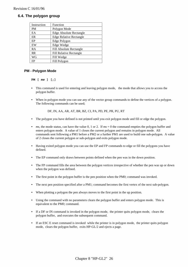
Revision C 16/01/96
Chapter 8 "HP-GL2" 26
6.4. The polygon group
Instruction FunctionPM Polygon ModeEA Edge Absolute RectangleER Edge Relative RectangleEP Edge PolygonEW Edge WedgeRA Fill Absolute RectangleRR Fill Relative RectangleWG Fill WedgeFP Fill Polygon
PM - Polygon Mode
PM [ ms ] [;]
• This command is used for entering and leaving polygon mode, the mode that allows you to access thepolygon buffer.
• When in polygon mode you can use any of the vector group commands to define the vertices of a polygon.The following commands can be used;
DF, IN, AA, AR, AT, BR, BZ, CI, PA, PD, PE, PR, PU, RT
• The polygon you have defined is not printed until you exit polygon mode and fill or edge the polygon.
• ms, the mode status, can have the value 0, 1 or 2. If ms = 0 the command empties the polygon buffer andenters polygon mode. A value of 1 closes the current polygon and remains in polygon mode. Allcommands sent following a PM1 before a PM2 or a further PM1 are used to build one sub-polygon. A valueof 2 closes the current polygon or sub-polygon and exits polygon mode.
• Having exited polygon mode you can use the EP and FP commands to edge or fill the polygons you havedefined.
• The EP command only draws between points defined when the pen was in the down position.
• The FP command fills the area between the polygon vertices irrespective of whether the pen was up or downwhen the polygon was defined.
• The first point in the polygon buffer is the pen position when the PM0; command was invoked.
• The next pen position specified after a PM1; command becomes the first vertex of the next sub-polygon.
• When plotting a polygon the pen always moves to the first point in the up position.
• Using the command with no parameters clears the polygon buffer and enters polygon mode. This isequivalent to the PM0; command.
• If a DF or IN command is invoked in the polygon mode, the printer quits polygon mode, clears thepolygon buffer, and executes the subsequent command.
• If an ESC E reset command is invoked while the printer is in polygon mode, the printer quits polygonmode, clears the polygon buffer, exits HP-GL/2 and ejects a page.
Revision C 16/01/96
Chapter 8 "HP-GL2" 27
EA - Edge Rectangle Absolute
EA X, Y[;]
X ; X coordinate of opposite corner for the rectangleY ; Y coordinate of opposite corner for the rectangle
• X and Y coordinates are absolute coordinates in current units.
• Plots the rectangle formed by the current position and the opposite corner specified by X and Y.
• After plotting, the cursor returns to its point of origin, and pen up/down status remains as selected.
• Plotting is performed whether the pen is up or down.
10 '-Edge Rectangle Absolute-20 WIDTH "LPT1:", 25530 LPRINT CHR$(27); "E";40 LPRINT CHR$(27); "%0B";50 LPRINT "IN;SP1;";60 LPRINT "SC0,150,0,150,1;"70 LPRINT "PA25;105;EA65;130;"80 LPRINT "PA30;110;EA70,135;"90 LPRINT "PA35;115;EA75;140;"100 LPRINT CHR$(27); "%0A";110 LPRINT CHR$(27); "E";120 END
<sample 31>
ER - Edge Rectangle Relative
ER X, Y[;]
X ; X coordinate of opposite corner for the rectangleY ; Y coordinate of opposite corner for the rectangle
• Coordinates are relative to the current position in current units.
• Plots the rectangle formed by the current position and the opposite corner specified by X and Y.
• After plotting, the cursor returns to its point of origin.
• Plotting is performed whether the pen is up or down.
10 '-Edge Rectangle Relative -20 WIDTH "LPT1:", 25530 LPRINT CHR$(27); "E";40 LPRINT CHR$(27); "%0B";50 LPRINT "IN;SP1;";60 LPRINT "SC0;150;0;150;1;"70 LPRINT "PA25,105;ER40,25;"80 LPRINT "PR 5, 5;ER40,25;"90 LPRINT "PR 5, 5;ER40,25;"100 LPRINT CHR$(27); "%0A";110 LPRINT CHR$(27); "E";120 END
<Sample 32>
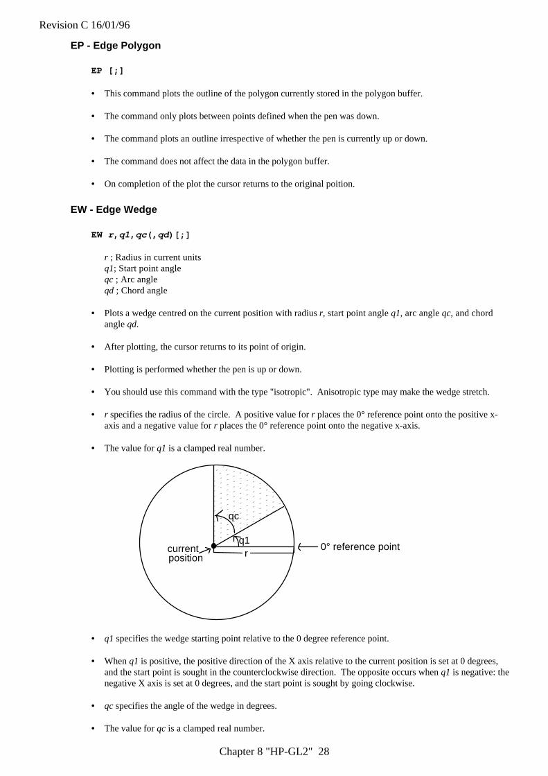
Revision C 16/01/96
Chapter 8 "HP-GL2" 28
EP - Edge Polygon
EP [;]
• This command plots the outline of the polygon currently stored in the polygon buffer.
• The command only plots between points defined when the pen was down.
• The command plots an outline irrespective of whether the pen is currently up or down.
• The command does not affect the data in the polygon buffer.
• On completion of the plot the cursor returns to the original poition.
EW - Edge Wedge
EW r , q1, qc (, qd)[;]
r ; Radius in current unitsq1; Start point angleqc ; Arc angleqd ; Chord angle
• Plots a wedge centred on the current position with radius r, start point angle q1, arc angle qc, and chordangle qd.
• After plotting, the cursor returns to its point of origin.
• Plotting is performed whether the pen is up or down.
• You should use this command with the type "isotropic". Anisotropic type may make the wedge stretch.
• r specifies the radius of the circle. A positive value for r places the 0° reference point onto the positive x-axis and a negative value for r places the 0° reference point onto the negative x-axis.
• The value for q1 is a clamped real number.
q1
qc
r0° reference pointcurrent
position
• q1 specifies the wedge starting point relative to the 0 degree reference point.
• When q1 is positive, the positive direction of the X axis relative to the current position is set at 0 degrees,and the start point is sought in the counterclockwise direction. The opposite occurs when q1 is negative: thenegative X axis is set at 0 degrees, and the start point is sought by going clockwise.
• qc specifies the angle of the wedge in degrees.
• The value for qc is a clamped real number.
Revision C 16/01/96
Chapter 8 "HP-GL2" 29
• Plotting proceeds counterclockwise when qc is positive, and clockwise when negative.
• The value for qd must be an integer from -32,768 to +32,767.
• When qd is not specified, the chord angle is the default value ( 5 degrees )
10 '- Edge Wedge -20 WIDTH "LPT1:", 25530 LPRINT CHR$(27); "E";40 LPRINT CHR$(27); "%0B";50 LPRINT "IN;SP1;"60 LPRINT "PA2000,5000;"70 LPRINT "EW1250,90,180,5;"80 LPRINT "EW1250,270,120;"90 LPRINT "EW1250,30,60;"100 LPRINT CHR$(27); "%0A";110 LPRINT CHR$(27); "E";120 END
<Sample 33>
RA - Fill Rectangle Absolute
RA X, Y[;]
X ; X coordinate of opposite corner for the rectangleY ; Y coordinate of opposite corner for the rectangle
• X and Y coordinates are absolute coordinates in current units.
• Fill the rectangle formed by the current position and the opposite corner specified by X and Y.
• After plotting, the cursor returns to its point of origin.
• Plotting is performed whether the pen is up or down.
10 ' - Fill Absolute Rectangle -20 WIDTH "LPT1:", 25530 LPRINT CHR$(27); "E";40 LPRINT CHR$(27); "%0B";50 LPRINT "IN;SP1;PA5000,4000;"60 LPRINT "FT1;RA4250,3250;"70 LPRINT "FT3,100;RA5750,3250;"80 LPRINT "FT2;RA5750,4750;"90 LPRINT "FT4,100,45;RA4250,4750;"100 LPRINT CHR$(27); "%0A";110 LPRINT CHR$(27); "E";120 END
<Sample 34>
Revision C 16/01/96
Chapter 8 "HP-GL2" 30
RR - Fill Rectangle Relative
RR X, Y[;]
X ; X coordinate of opposite corner for the rectangleY ; Y coordinate of opposite corner for the rectangle
• Coordinates relative to the current position in current units.
• Fill the rectangle formed by the current position and the opposite corner specified by X and Y.
• After plotting the cursor returns to its point of origin.
• Plotting is performed whether the pen is up or down.
10 ' - Fill Relative Rectangle -20 WIDTH "LPT1:", 25530 LPRINT CHR$(27); "E";40 LPRINT CHR$(27); "%0B";50 LPRINT "IN;SP1;PA5000,4000;"60 LPRINT "FT1;RR750,750;"70 LPRINT "PR750,0;"80 LPRINT "FT3,100;RR750,750;"90 LPRINT "PR0,750;"100 LPRINT "FT2;RR750,750;"110 LPRINT "FT4,100,45;RR-750,750;"120 LPRINT CHR$(27); "%0A";130 LPRINT CHR$(27); "E";140 END
<Sample 35>
Revision C 16/01/96
Chapter 8 "HP-GL2" 31
WG - Fill Wedge
WG r , q1, qc (, qd)[;]
r ; Radius in current unitsq1 ; Start point angleqc ; Arc angleqd ; Chord angle
• Fill in a wedge centred on the current position with radius r, start point angle q1, arc angle qc, and chordangle qd.
• After plotting, the cursor returns to its point of origin.
• Plotting is performed whether the pen is up or down.
• You should use this command with the type "isotropic". Anisotropic type may make the wedge stretch.
• r specifies the radius of circle. A positive value places the 0° reference point onto the positive x-axis andthe negative value places it onto the negative x-axis.
• The value for q1 is a clamped real number.
• q1 specifies the wedge starting point related to the 0° reference point.
• When q1 is positive, the positive direction of the X axis relative to the current position is set at 0 degrees,and the start point is sought in the counterclockwise direction. The opposite occurs when q1 is negative: thenegative X axis is set at 0 degrees, and the start point is sought by going clockwise.
• qc specifies the angle of the wedge.
• The value for qc is a clamped real number.
• Plotting proceeds counterclockwise when qc is positive, and clockwise when negative.
• The value for qd is a clamped real number.
• When qd is not specified, the chord angle is the default value ( 5 degrees ).
10 ' - Fill Wedge -20 WIDTH "LPT1:", 25530 LPRINT CHR$(27); "E";40 LPRINT CHR$(27); "%0B";50 LPRINT "IN;SP2;FT3,100;"60 LPRINT "PA2000,5000;"70 LPRINT "WG1250,90,180,5;"80 LPRINT "SP3;EW1250,90,180,5;"90 LPRINT "SP4;FT4,100,45;"100 LPRINT "WG1250,270,120;"110 LPRINT "SP3;EW1250,270,120;"120 LPRINT "SP1;FT1;"130 LPRINT "WG1250,30,60;"140 LPRINT "SP3;EW1250,30,60;"150 LPRINT CHR$(27); "%0A";160 LPRINT CHR$(27); "E";170 END
<Sample 36>
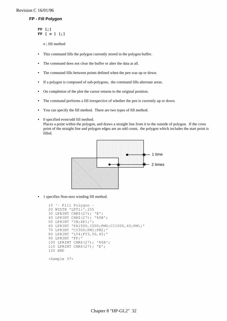
Revision C 16/01/96
Chapter 8 "HP-GL2" 32
FP - Fill Polygon
FP [;]FP [ n ] [;]
n ; fill method
• This command fills the polygon currently stored in the polygon buffer.
• The command does not clear the buffer or alter the data at all.
• The command fills between points defined when the pen was up or down.
• If a polygon is composed of sub-polygons, the command fills alternate areas.
• On completion of the plot the cursor returns to the original position.
• The command performs a fill irrespective of whether the pen is currently up or down.
• You can specify the fill method. There are two types of fill method.
• 0 specified even/odd fill method.Places a point within the polygon, and draws a straight line from it to the outside of polygon. If the crosspoint of the straight line and polygon edges are an odd count, the polygon which includes the start point isfilled.
* **
2 times
1 time
• 1 specifies Non-zero winding fill method.
10 '- Fill Polygon -20 WIDTH "LPT1:",25530 LPRINT CHR$(27); "E";40 LPRINT CHR$(27); "%0B";50 LPRINT "IN;SP1;";60 LPRINT "PA1500,1500;PM0;CI1000,60;PM1;"70 LPRINT "CI500;PM1;PM2;"80 LPRINT "LT4;FT3,50,45;"90 LPRINT "FP;"100 LPRINT CHR$(27); "%0A";110 LPRINT CHR$(27); "E";120 END
<Sample 37>

Revision C 16/01/96
Chapter 8 "HP-GL2" 33
6.5. Plot Function Instructions
Instruction FunctionAC Anchor CornerFT Fill TypeLA Line AttributeLT Line TypePW Pen WidthRF Raster Fill DefinitionSM Symbol ModeSP Select PenSV Screened VectorsTR Transparency ModeUL User-defined Line TypeWU Select Unit for Pen Width
AC - Anchor Corner
AC [ X, Y ] [;]
X ; x-coordinate of starting point of fill patternY ; y-coordinate of starting point of fill pattern
• This command specifies the anchor corner which is the starting position of a fill pattern.
• If no parameters are specified the lower left hand corner of the PCL picture frame, according to the currentcoordinate system, becomes the anchor position. This is equivalent to AC0,0;
• User units or graphics units may be used.
• The value of the coordinates are real numbers in the range (-230) to 230 - 1.
10 '-Anchor Corner -20 WIDTH "LPT1:",25530 LPRINT CHR$(27); "E";40 LPRINT CHR$(27); "%0B";50 LPRINT "IN;SP1;";60 LPRINT "PA3000,3000;FT3,400,45;"70 LPRINT "RR1000,1000;ER1000,1000;"80 LPRINT "PR1000,0;FT4,400,45;"90 LPRINT "RR1000,1000;ER1000,1000;"100 LPRINT "PR1000,0;FT3,400,45;"110 LPRINT "RR1000,1000,ER1000,1000;"120 LPRINT "PA3000,1500;AC3000,1500;"130 LPRINT "RR1000,1000;ER1000,1000;"140 LPRINT "PA4000,1500;AC4000,1500;FT4,400,45;"150 LPRINT "RR1000,1000;ER1000,1000;"160 LPRINT "PA5000,1500;AC5000,1500;FT3,400,45;"170 LPRINT "RR1000,1000;ER1000,1000;"180 LPRINT CHR$(27); "%0A";190 LPRINT CHR$(27); "E";200 END
<Sample 38>
Revision C 16/01/96
Chapter 8 "HP-GL2" 34
FT - Fill Type
FT n(, d(, q))[;]
n ; Fill type d ; option 1 q ; option 2
• Sets the fill type, interval, and angle when filling an area. This setting is effective for the commands FP,RA, RR, WG and CF.
• The value for n must be a clamped integer number
Fill type Description Option 1 Option 21 Solid black (bidirectional fill)2 Solid black (single directional fill)3 hatching (parallel line) fill interval fill angle4 cross-hatching fill interval fill angle10 shading shading level11 HP-GL/2 user-defined raster-fill index21 PCL cross-hatching pattern type22 PCL user-defined pattern ID130 shading (one of sixty-four gray scales) Shading level
• option 1 for n=3 or 4 is the setting for the interval of the lines in the fill. This is specified in current units.
• If d is omitted or 0, it is set to default value which is 1% of the diagonal distance between P1 and P2.
• Option 2 for n=3 and 4 is the setting of the angle for the lines in degrees.
• If q is omitted, the fill angle already specified will be used.
• The value of q is a clamped real number.
• Option 1 for n=10 is the setting for the shading density. It is specified as a percentage from 0 to 100.
• Option 2 for n=10 is ignored.
• Option 1 for n=11 specifies the HP-GL/2 user-defined raster fill pattern. This uses the index number whichis defined by the RF command.
• Option 2 for n=11 is ignored.
• Option 1 for n=21 specifies the PCL cross-hatch patterns. There are 6 types of PCL cross-hatch patterns.
• Option 2 for n=21 is ignored.
• Option 1 for n=22, the PCL user-defined patterns defined by ESC*c#W command with a unique ID code.
• Option 2 for n=22 is ignored.
• Option 1 for n=130, the 64 gray scale shading density. It is specified as a percentage from 0 to 100.
• Option 2 for n=130 is ignored.
10 ' - Fill Type -20 WIDTH "LPT1:", 25530 LPRINT CHR$(27); "E";40 LPRINT CHR$(27); "%0B";50 LPRINT "IN;SP1;";60 LPRINT "PA2000,2000;FT;PR2500,300;ER2500,300;"70 LPRINT "PR0,300;FT3,80,30;RR2500.300;"80 LPRINT "PR0,300;FT10,36;RR2500,300;ER2500,300;"90 LPRINT CHR$(27); "%0A";100 LPRINT CHR$(27); "E";110 END
<Sample 39>
LA - Line Attribute
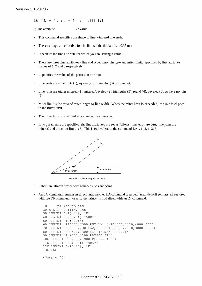
Revision C 16/01/96
Chapter 8 "HP-GL2" 35
LA [ ll, v [ , ll , v [ , ll , v]]] [;]
l ; line attribute v : value
• This command specifies the shape of line joins and line ends.
• These settings are effective for the line widths thicker than 0.35 mm.
• l specifies the line attribute for which you are setting a value.
• There are three line attributes - line end type, line join type and miter limit, specified by line attributevalues of 1, 2 and 3 respectively.
• v specifies the value of the particular attribute.
• Line ends are either butt (1), square (2,), triangular (3) or round (4).
• Line joins are either mitered (1), mitered/beveled (2), triangular (3), round (4), beveled (5), or have no join(6).
• Miter limit is the ratio of miter length to line width. When the miter limit is exceeded, the join is clippedto the miter limit.
• The miter limit is specified as a clamped real number.
• If no parameters are specified, the line attributes are set as follows: line ends are butt, line joins aremitered and the miter limit is 5. This is equivalent to the command LA1, 1, 2, 1, 3, 5;
Miter lengthLine width
Miter limit = Miter length / Line width
• Labels are always drawn with rounded ends and joins.
• An LA command remains in effect until another LA command is issued, until default settings are restoredwith the DF command, or until the printer is initialized with an IN command.
10 '-Line Attributes-20 WIDTH "LPT1:", 25530 LPRINT CHR$(27); "E";40 LPRINT CHR$(27); "%0B";50 LPRINT "IN;SP1;";60 LPRINT "PA4000,3000;PW2;LA1,3;PD3500,2500,4000,2000;"70 LPRINT "PU3500,200;LA2,2,3,20;PD3000,2500,3000,2300;"80 LPRINT "PU2500,2300;LA1,4;PD3500,2300;"90 LPRINT "PU2700,2100;PD3300,2100;"100 LPRINT "PU2900,1900;PD3100,1900;"110 LPRINT CHR$(27); "%0A";120 LPRINT CHR$(27); "E";130 END
<Sample 40>
Revision C 16/01/96
Chapter 8 "HP-GL2" 36
LT - Line Type Selection
LT [, n [, p [, m ]]] [;]
n ; Line pattern numberp ; Line pattern length (percentage or millimeters of distance between P1 and P2)m : mode
• This command specifies the line pattern for use when drawing lines with the vector group commands.
• n defines the line type to be used. n is either in the range -8 to 8 or is 99.
• Values of n from 1 to 8 specify a line type (as defined with the UL command) and use a fixed pattern length.Any residual part of the pattern not used on a particular drawing operation is stored and used at the start ofthe next line drawn.
• Values of n from -1 to -8 specify a line type (as defined with the UL command) and use an adaptive patternlength - that is, the pattern is scaled so as to fit one or more complete patterns into the line.
• If n is 0, a dot is placed at the (X, Y) coordinates specified with any vector commands used.
• p, the pattern length, specifies the length of one complete pattern, either as a percentage of the distancebetween P1 and P2, or in millimeters. The unit system used is determined by the mode setting. If thelength is omitted, the printer uses the most recently specified pattern length.
• If a zero or negative pattern length is specified, the command is ignored.
• m, the mode, defines whether the pattern length parameter, p, is interpreted as a reading in millimeters,(m=1), or as a percentage of the distance between P1 and P2, (m=0). If no mode number is included in thecommand, the most recently specified mode is used.
• LT99; restores the previous line type (and, if it is a fixed line type, the residue), provided that the currentline type is solid and that the pen position is the same as it was when the current, solid line type wasselected.
• An LT command remains in effect until another LT command is issued, until the default settings arerestored with the DF command, or until the printer is initialized with an IN command.
• If no parameters are specified the line type is set to be solid. The previous line type, pattern length and anyline residue are saved.
Revision C 16/01/96
Chapter 8 "HP-GL2" 37
10 ' - Line Type -20 WIDTH "LPT1:", 25530 LPRINT CHR$(27); "E";40 LPRINT CHR$(27); "%0B";50 LPRINT "IN;IP1000,1000,9000,7000;SP1;";60 LPRINT "PA2000,7100;PDPR400,0;PU;" 'REM DEFAULT LINE = 40070 LPRINT "LT8;PA2000,7000;PD5000,7000;PU;"80 LPRINT "LT8,4,0;PA2000,6900;PD5000,6900;PU;"90 LPRINT "LT8,8,1;PA2000,6800;PD5000L6800;PU;"100 '110 LPRINT "LT4,PA2000,6600;PD5000,6600;PU;"120 LPRINT "LT4,4,0;PA2000;6500;PD5000;6600;PU;"130 LPRINT "LT4,10,1;PA2000,6400;PD5000,6400;PU;"140 '150 LPRINT "LT0;PA2000,6300;PD5000,6200; PU;"160 LPRINT "LT0,4,0;PA2000,6100;PD5000,61000;PU;"170 LPRINT "LT0,10,1;PA2000,6000;PD5000,6000;PU;"180 '190 LPRINT "LT-4;PA2000,5800;PD5000,5800;PU;"200 LPRINT "LT-4,4,0;PA2000,5700;PD5000;5700;PU;"210 LPRINT "LT-4,10,1;PA2000,5600;PD5000,5600;PU;"220 '230 LPRINT "LT-8;PA2000,5400;PD5000,5400;PU;"240 LPRINT "LT-8,4,0;PA2000,5300;PD5000,5300;PU;"250 LPRINT "LT08,10,1;PA2000,5200;PD5000,5200;PU;"260 '270 LPRINT "LT99;PA2000,5000;PD5000,5000;PU;"280 LPRINT CHR$(27); "%0A";290 LPRINT CHR$(27); "E";300 END
<Sample 41>
Revision C 16/01/96
Chapter 8 "HP-GL2" 38
PW - Pen Width
PW [ w, [, p]] [;]
w ; widthp ; pen
• This command specifies the width of the pen.
• Pen width can either be specified as a fixed width in millimeters ( the default ) or relative to the distancebetween the scaling points P1 and P2.
• If a width of zero is specified the thinnest width possible ( 1 dot wide ) is set.
• Metric widths are scaled by the ratio of the PCL picture frame to the HP-GL/2 plot size. If the ratio for thetwo axes is different, the smaller one is used. If this is less than the thinnest width available then a widthof 1 dot is selected.
• If no pen number is specified the new width applies to both pens.
• If a pen number other than 0 or 1 is specified the command is ignored. There are six pens in thespecification.
• If no parameters are specified the pen width defaults to either 0.35mm or 0.1% of the distance from P1 toP2 according to the current width unit setting.
• Pen width settings are not affected by a DF command.
• Pen width does not set the width of the lines that make up the characters in a label.
• A PW command remains in effect until another PW command is issued, until a WU command is used, oruntil the printer is initialized with an IN command.
10 '-Pen Width-20 WIDTH "LPT1:", 25530 LPRINT CHR$(27); "E";40 LPRINT CHR$(27); "%0B";50 LPRINT "IN;SP1;";60 LPRINT "PA3500,2500;PW1.5;"70 LPRINT "PD4500,2800,4500,1800,3500,1500,3500,2500;"80 LPRINT "PW0.8;PD2300,2900,2300,1900,3500,1500;"90 LPRINT "PW0.5;PU2300,2900;PD3300,3200,4500,2800;"100 LPRINT "PW0.25:PU4500,1800;PD3500,2100;"110 LPRINT CHR$(27); "%0A";120 LPRINT CHR$(27); "E";130 END
<Sample 42>
Revision C 16/01/96
Chapter 8 "HP-GL2" 39
RF - Raster Fill Definition
RF [ i [, w, h, p [,...]]] [;]
i : index w : widthp: pen number h : height
• This command defines a rectangular pattern which may be used to fill the area.
• i is the index number of the pattern that is to be defined and must be in the range 1-8. 8 patterns can existconcurrently.
• If used with an index parameter and no others, the pattern is defined as a solid black fill.
• w is the width in pixels of the pattern that is to be defined and must be in the range 1- 255.
• h is the height in pixels of the pattern that is to be defined an must be in the range 1 - 255.
• p stands for a pixel in the defined fill. p = 0 signifies a white pixel, p>0 signifies a black pixel. Thenumber of pixels specified should equal the number of pixels in the fill pattern (w, h). The parameterdefines successive pixels' colors from left to right, top to bottom. If you do not supply enough pixelparameters the trailing pixels default to white.
• Use the FT command to select a fill type from those defined with the RF command.
• Omitting parameters sets all raster fill patterns to solid fill.
10 '--Raster Fill Definition==20 WIDTH "LPT1:", 25530 LPRINT CHR$(27); "E";40 LPRINT CHR$(27); "%0B";50 LPRINT "IN;SP1;";60 LPRINT "PU5,5;PA3500,2500;"70 LPRINT"RF2,8,4,0,0,0,0,0,0,0,0,0,0,0,1,1,0,0,0,0,0,1,1,0,0,0,0,0,0,0,0,0,0,0,0,;"80 LPRINT "FT11,2;RR4000,800;EP;"90 LPRINT CHR$(27); "%0A";100 LPRINT CHR$(27); "E";110 END
<Sample 43>
Revision C 16/01/96
Chapter 8 "HP-GL2" 40
SM - Symbol Mode
SM c[;]
c ; ASCII character or symbol code
• The command specifies the symbol to be drawn.
• The specified symbol will be drawn at the end of each vector, irrespective of whether the pen is up or down,when the PA, PR, PD, PU or PE instructions are used.
• Characters in the character code ranges 33 - 58, 60 - 126 and characters 161 and 254 can be used.
• Character code 59 stands for the ';', which is the HP-GL/2 terminator. You cannot use it as a symbol.
• The current character size, slant and direction settings affect the way the symbol is drawn.
• Omitting the parameter cancels the symbol mode.
• On quitting symbol mode the original pen up/down state is restored.
SP - Select Pen
SP [ n ] [;]
n ; pen number
• The command selects a pen for drawing.
• You must use this command before performing any drawing or filling commands.
• n should be either 0 or 1 ( although any other integers will be interpreted as 1.)
• If n is 0 the white pen is selected. In this case drawing commands will have no effect, unless you areplotting onto a dark background and transparency mode is off.
• If n is 1 the black pen is selected and printing can proceed normally. Use SP1; at the start of HP-GL/2programs.
• Invoking the command with no parameter is equivalent to SP0;.
Revision C 16/01/96
Chapter 8 "HP-GL2" 41
SV - Screened Vectors
SV [ s [, option _1[, option _2]]] [;]
s : screen typeoption_1 and option_2: dependent on the screen type
• This command selects the type of screening that will be applied to vectors, arcs, circles and edges ofpolygons, rectangles and wedges.
• The screen type must have the value 0, 1, 2, 21, 22 or 130. 0 = no screen, 1 = shaded fill ( one of eightgray scales ), 2 = raster fill as defined by the RF command, 21 = a pre-defined PCL cross-hatch pattern and130 = shaded fill ( one of sixty-four gray scales ).
• With screen type 1 option_1 specifies the percentage of shading (0-100): option_2 is ignored.
• With screen type 2 option_1 is used to specify the index number of the fill pattern created using the RFcommand. Option_2 is set to either 0 or 1: 0 means that the fill will appear in the colour of pen number 1,1 means it should appear in the current pen's colour.
• With screen type 21 option 1 specifies one of six predefined PCL cross-hatch patterns (patterns 1 - 6).option 2 is ignored.
• With screen type 22, option 1 specifies the ID number of PCL user-defined pattern which is defined by theESC*c#W command. option 2 is ignored.
• With fill screen type 130 option 1 specifies the percentage of shading ( 0 - 100 ): option 2 is ignored.
• If option 1 and option 2 are omitted, the most recently specified values for these parameters, for thespecified screen type, are used.
• All screening patterns use the current anchor corner.
• Invoking the command with no parameter turns screening off. This is equivalent to SV0;
10 '-Screened Vectors-20 WIDTH "LPT1:", 25530 LPRINT CHR$(27); "E";40 LPRINT CHR$(27); "%0B";50 LPRINT "IN;SP1;";60 LPRINT "SV1,15;PA4000,5000;CI500;"70 LPRINT "SV1,50;PA5000,4000;CI400;"80 LPRINT "SV1,100;PA6000,6000;CI300;"90 LPRINT "PW10;SV21,5;PA2000,1000;PD;AA0,0,90;PC;"100 LPRINT "PW5;SV21,3;PA6000,6000;CI500;"110 LPRINT "PW7;SV21,6;PA2000,8000;PDPA5000,8000;PU;"120 LPRINT "PW7;SV21,6;PA2000,8000;PDPA5000,8000;PU;"130 LPRINT "1,1,0,0,0,0,0,0,1,1,";140 LPRINT "0,0,1,1,0,0,1,1,0,0,";150 LPRINT "0,0,0,0,1,1,0,0,0,0,";160 LPRINT "0,0,1,1,0,0,1,1,0,0,";170 LPRINT "1,1,0,0,0,0,0,0,1,1;";180 LPRINT"PW15;SV2,3;PA4000,2000;PM0;PD6000,2000,6000,4000,4000,4000;PM1;PM2;EP;"190 LPRINT CHR$(27); "%0A";200 LPRINT CHR$(27); "E";210 END
<Sample 44>
Revision C 16/01/96
Chapter 8 "HP-GL2" 42
TR - Transparency Mode
TR [ n ] [;]
n ; transparency type
• This command turns transparency mode on and off. Transparency mode defines how source and destinationgraphics images interact.
• n is either 0 (off) or 1(on).
• When transparency mode is on, the white parts of a source image (the image that is being superimposed onthe destination image) do not affect the destination image - that is, part of the destination image will bevisible beneath the source image.
• When transparency mode is off the destination image is not visible beneath the source image.
• Invoking the command with no parameter turns transparency mode on. This is equivalent to TR1;
• An Esc E reset, a control panel reset, the IN command and the DF command all turn transparency modeon.
10 'Transparency Mode-20 WIDTH "LPT1:", 25530 LPRINT CHR$(27); "E";40 LPRINT CHR$(27); "%0b";50 LPRINT "IN;SP1;";60 'PART1 TR170 'Original Destination 180 LPRINT "TR1;PA1900,4900;PM0;PM3100;4900,2500,6100;PM1;"90 LPRINT "PM2;FP;"100 'Source 1110 LPRINT "FT10,50;PA2000,5000;RR500,500;PA2500,5500;RR500,500;"120 LPRINT "FT10,1;PA2500,5000;RR500,500;PA2000,5500;RR500,500;FT;"130 'PART2 TR0140 'Original Destination 2150 LPRINT "TR0;PA3900,4900;PM0;PA5100,4900,4500,6100;PM1;"160 LPRINT "PM2;FP;"170 'Source 2180 LPRINT "FT10,50;PA4000,5000;RR500,500;PA4500,5500;RR500,500;"190 LPRINT "FT10,1;PA4500,5000;RR500,500;PA4000,5500;RR500,500;FT;"200 '210 '( POLYGON )220 LPRINT "PA2000,1000;PM0;PDPA4000,1000,3000,3000;PM1;"230 LPRINT "PA2500,1200,3500,1200,3000,2500;PM1;"240 LPRINT "PA3000,800,3700,2500,2300,2500;PM1;"250 LPRINT "PM2;FP;"260 LPRINT CHR$(27); "%0A";270 LPRINT CHR$(27); "E";280 END
<Sample 45>
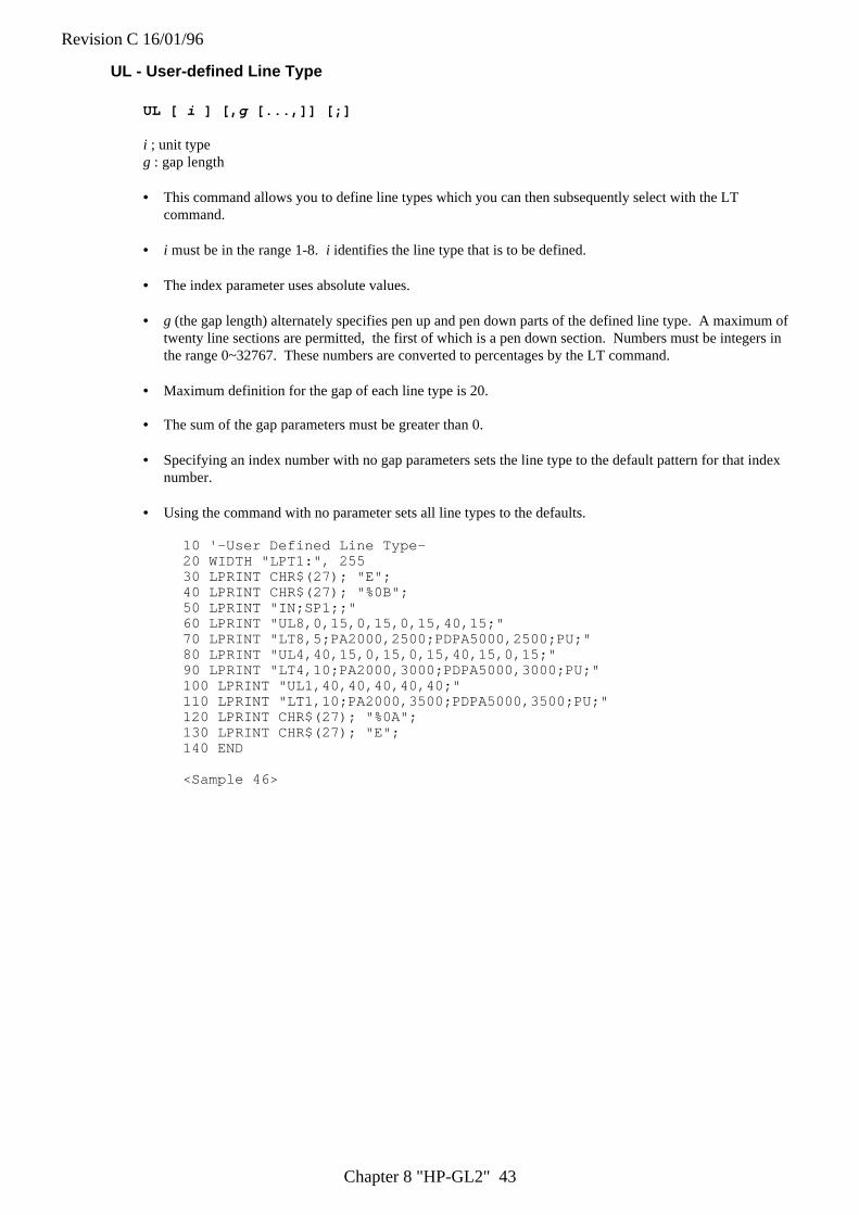
Revision C 16/01/96
Chapter 8 "HP-GL2" 43
UL - User-defined Line Type
UL [ i ] [, g [...,]] [;]
i ; unit typeg : gap length
• This command allows you to define line types which you can then subsequently select with the LTcommand.
• i must be in the range 1-8. i identifies the line type that is to be defined.
• The index parameter uses absolute values.
• g (the gap length) alternately specifies pen up and pen down parts of the defined line type. A maximum oftwenty line sections are permitted, the first of which is a pen down section. Numbers must be integers inthe range 0~32767. These numbers are converted to percentages by the LT command.
• Maximum definition for the gap of each line type is 20.
• The sum of the gap parameters must be greater than 0.
• Specifying an index number with no gap parameters sets the line type to the default pattern for that indexnumber.
• Using the command with no parameter sets all line types to the defaults.
10 '-User Defined Line Type-20 WIDTH "LPT1:", 25530 LPRINT CHR$(27); "E";40 LPRINT CHR$(27); "%0B";50 LPRINT "IN;SP1;;"60 LPRINT "UL8,0,15,0,15,0,15,40,15;"70 LPRINT "LT8,5;PA2000,2500;PDPA5000,2500;PU;"80 LPRINT "UL4,40,15,0,15,0,15,40,15,0,15;"90 LPRINT "LT4,10;PA2000,3000;PDPA5000,3000;PU;"100 LPRINT "UL1,40,40,40,40,40;"110 LPRINT "LT1,10;PA2000,3500;PDPA5000,3500;PU;"120 LPRINT CHR$(27); "%0A";130 LPRINT CHR$(27); "E";140 END
<Sample 46>
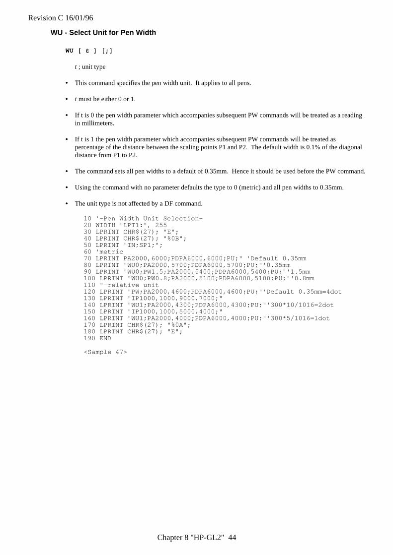
Revision C 16/01/96
Chapter 8 "HP-GL2" 44
WU - Select Unit for Pen Width
WU [ t ] [;]
t ; unit type
• This command specifies the pen width unit. It applies to all pens.
• t must be either 0 or 1.
• If t is 0 the pen width parameter which accompanies subsequent PW commands will be treated as a readingin millimeters.
• If t is 1 the pen width parameter which accompanies subsequent PW commands will be treated aspercentage of the distance between the scaling points P1 and P2. The default width is 0.1% of the diagonaldistance from P1 to P2.
• The command sets all pen widths to a default of 0.35mm. Hence it should be used before the PW command.
• Using the command with no parameter defaults the type to 0 (metric) and all pen widths to 0.35mm.
• The unit type is not affected by a DF command.
10 '-Pen Width Unit Selection-20 WIDTH "LPT1:", 25530 LPRINT CHR$(27); "E";40 LPRINT CHR$(27); "%0B";50 LPRINT "IN;SP1;";60 'metric70 LPRINT PA2000,6000;PDPA6000,6000;PU;" 'Default 0.35mm80 LPRINT "WU0;PA2000,5700;PDPA6000,5700;PU;"'0.35mm90 LPRINT "WU0;PW1.5;PA2000,5400;PDPA6000,5400;PU;"'1.5mm100 LPRINT "WU0;PW0.8;PA2000,5100;PDPA6000,5100;PU;"'0.8mm110 "-relative unit120 LPRINT "PW;PA2000,4600;PDPA6000,4600;PU;"'Default 0.35mm=4dot130 LPRINT "IP1000,1000,9000,7000;"140 LPRINT "WU1;PA2000,4300;PDPA6000,4300;PU;"'300*10/1016=2dot150 LPRINT "IP1000,1000,5000,4000;"160 LPRINT "WU1;PA2000,4000;PDPA6000,4000;PU;"'300*5/1016=1dot170 LPRINT CHR$(27); "%0A";180 LPRINT CHR$(27); "E";190 END
<Sample 47>
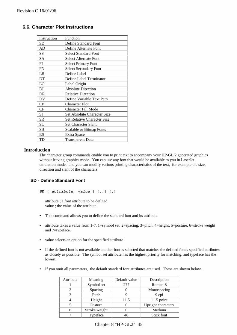
Revision C 16/01/96
Chapter 8 "HP-GL2" 45
6.6. Character Plot Instructions
Instruction FunctionSD Define Standard FontAD Define Alternate FontSS Select Standard FontSA Select Alternate FontFI Select Primary FontFN Select Secondary FontLB Define LabelDT Define Label TerminatorLO Label OriginDI Absolute DirectionDR Relative DirectionDV Define Variable Text PathCP Character PlotCF Character Fill ModeSI Set Absolute Character SizeSR Set Relative Character SizeSL Set Character SlantSB Scalable or Bitmap FontsES Extra SpaceTD Transparent Data
IntroductionThe character group commands enable you to print text to accompany your HP-GL/2 generated graphicswithout leaving graphics mode. You can use any font that would be available to you in LaserJetemulation mode, and you can modify various printing characteristics of the text, for example the size,direction and slant of the characters.
SD - Define Standard Font
SD [ attribute, value ] [..] [;]
attribute ; a font attribute to be definedvalue ; the value of the attribute
• This command allows you to define the standard font and its attribute.
• attribute takes a value from 1-7. 1=symbol set, 2=spacing, 3=pitch, 4=height, 5=posture, 6=stroke weightand 7=typeface.
• value selects an option for the specified attribute.
• If the defined font is not available another font is selected that matches the defined font's specified attributesas closely as possible. The symbol set attribute has the highest priority for matching, and typeface has thelowest.
• If you omit all parameters, the default standard font attributes are used. These are shown below.
Attribute Meaning Default value Description1 Symbol set 277 Roman-82 Spacing 0 Monospacing3 Pitch 9 9 cpi4 Height 11.5 11.5 point5 Posture 0 Upright characters6 Stroke weight 0 Medium7 Typeface 48 Stick font

Revision C 16/01/96
Chapter 8 "HP-GL2" 46
• attribute = 1 : Symbol set
Value
Name ISOnumber
Value
Name ISOnumber
1 Math - 7 - 2 Line Draw - 7 -3 HP Large Characters - 4 Norwegian v1 605 Roman Extensions - 6 French v1 257 HP German - 8 Hebrew - 7 -9 Italian 15 11 JIS ASCII 1412 Line Draw - 7 - 13 Math - 7 -14 ECMA-94 Latin1 (8-bit
version)8859/1 15 OCR - A -
16 APL (typewriter paired) - 18 Cyrillic ASCII -19 Swedish for names 11 20 Thai - 8 -21 ASCII 6 22 Arabic (MacKay's
Version)-
25 3 of 9 Barcode - 26 Not used -36 Danish/Norwegian v2 61 37 United Kingdom 438 French v2 69 39 German 2143 Katakana 13 44 HP Block Characters -45 Tech - 7 - 47 OCR - B -48 APL (bit paired) - 50 Cyrillic -51 HP Spanish - 53 Legal -57 Industrial 2 of 5 Barcode - 75 Chinese 5776 Tax Line Draw - 78 ECMA-94 Latin 2 8859/279 OCR-M - 83 Spanish 1785 International Reference
Version2 89 Matrix 2 of 5 Barcode -
114 PC Cyrillic - 115 Swedish 10147 Portuguese 16 153 Interleaved 2 of 5 Barcode -173 PS Math - 174 ECMA-128 Latin 5 8859/9179 Portuguese 84 181 HPL Language Set -185 CODABAR Barcode - 202 Microsoft Publishing -205 Ventura Math - 211 Spanish 85217 MSI/Plessey Barcode - 234 DeskTop -243 HP European Spanish - 249 Code 11 Barcode -263 Greek - 8 - 264 Hebrew - 8 -266 Document - 267 Kana - 8 -268 Line Draw 8 - 269 Math - 8 -275 HP Latin Spanish - 276 Turkish - 8 -277 Roman - 8 (Default) - 278 Arabic - 8 -281 UPC/EAN Barcode - 299 Korean - 8 -309 Windows - 330 PS Text -332 PS ITC Zapf Dingbats - 334 ECMA-113/88
Latin/Cyrillic8859/5.2
341 PC-8 - 373 PC-8 D/N -405 PC-850 - 428 ITC Zapf Dingbats Series
300-
458 Ventura U.S. - 501 Pi Font -505 USPS Zip - 531 HP-GL Download -563 HP-GL Drafting - 595 HP-GL Special Symbols -
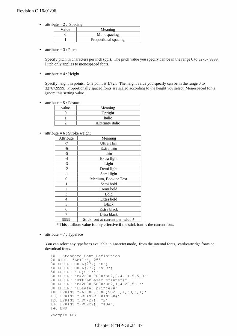
Revision C 16/01/96
Chapter 8 "HP-GL2" 47
• attribute = 2 : SpacingValue Meaning
0 Monospacing1 Proportional spacing
• attribute = 3 : Pitch
Specify pitch in characters per inch (cpi). The pitch value you specify can be in the range 0 to 32767.9999.Pitch only applies to monospaced fonts.
• attribute = 4 : Height
Specify height in points. One point is 1/72". The height value you specify can be in the range 0 to32767.9999. Proportionally spaced fonts are scaled according to the height you select. Monospaced fontsignore this setting value.
• attribute = 5 : Posturevalue Meaning
0 Upright1 Italic2 Alternate italic
• attribute = 6 : Stroke weightAttribute Meaning
-7 Ultra Thin-6 Extra thin-5 thin-4 Extra light-3 Light-2 Demi light-1 Semi light0 Medium, Book or Text1 Semi bold2 Demi bold3 Bold4 Extra bold5 Black6 Extra black7 Ultra black
9999 Stick font at current pen width** This attribute value is only effective if the stick font is the current font.
• attribute = 7 : Typeface
You can select any typefaces available in LaserJet mode, from the internal fonts, card/cartridge fonts ordownload fonts.
10 '-Standard Font Definition-20 WIDTH "LPT1:", 25530 LPRINT CHR$(27); "E";40 LPRINT CHR$(27); "%0B";50 LPRINT "IN;SP1;";60 LPRINT "PA2200,7000;SD2,0,4,11.5,5,0;"70 LPRINT "DT#;LBLaser printer#"80 LPRINT "PA2000,5000;SD2,1,4,20,5,1;"90 LPRINT "LBLaser printer#"100 LPRINT "PA1000,3000;SD2,1,4,50,5,1;"110 LPRINT "LBLASER PRINTER#"120 LPRINT CHR$(27); "E";130 LPRINT CHR$927); "%0A";140 END
<Sample 48>

Revision C 16/01/96
Chapter 8 "HP-GL2" 48
AD - Define Alternate Font
AD [ attribute , value ] [..] [;]
attribute : a font attribute to be definedvalue : the value of the attribute
• This command allows you to define the alternate font and its attribute.
• attribute takes a value from 1-7.1 = symbol set, 2 = spacing, 3 = pitch, 4 = height, 5 = posture, 6 = stroke weight and 7 = typeface.
• value selects an option for the specified attribute. For further explanation about attribute values, see theprevious SD command.
• If the defined font is not available, another font is selected that matches the defined font's specifiedattributes as closely as possible. The symbol set attribute has the highest priority for matching, andtypeface has the lowest.
• If you omit all parameters, the default alternate font attributes are used.
10 '-Define Alternate Font -20 WIDTH "LPT1:", 25530 LPRINT CHR$(27); "E";40 LPRINT CHR$(27); "%0B";50 LPRINT "IN;SP1;";60 '- Standard font -70 LPRINT "PA1000,5000;"80 LPRINT "LBStandard font"; CHR$(3);90 ' - Alternate font -100 LPRINT "AD2,1,4,24,7,4101;"110 LPRINT "PA1000,4000;"120 LPRINT "SA";130 LPRINT "LBAlternate font"; CHR$(3);140 LPRINT CHR$(27); "%0A";150 LPRINT CHR$(27); "E";160 END
<Sample 49>
SS - Select Standard Font
SS [;]
• This command allows you to select the standard font, as defined by the SD command. All subsequentlyprinted labels will appear in the standard font.
• The SS command is equivalent to including the SI control code (ASCII 15) in a label.
• The default standard font is the HP-GL stick font.
• The font remains current until the printer is initialized with an IN command, until the default conditions areresorted with the DF command, or until an SA command is used.
Revision C 16/01/96
Chapter 8 "HP-GL2" 49
SA - Select Alternate Font
SA [;]
• This command allows you to select the alternate font, as defined by the AD command. All subsequentlyprinted labels will appear in the alternate font
• The SA command is equivalent to including the SO control code (ASCII 14) in a label.
• The font remains current until the printer is initialized with an IN command, until the default conditionsare restored with the DF command, or until an SS command is used.
FI - Select Primary Font
FI font-ID [;]
font-ID ; the identity number of any accessible font.
• This command allows you to select any accessible font, which has previously been given an identity numberin LaserJet mode, as the primary (standard) font. All subsequently printed labels will appear in the primaryfont.
• For scalable fonts this command must be preceded by an SD command specifying the font's point size orpitch.
• When the FI command is issued the primary (standard) font's attributes are set to be those of the selectedfont (provided it is available).
10 '-Select Primary Font & Select standard Font -20 WIDTH "LPT1:",25530 LPRINT CHR$(27); "E";40 LPRINT CHR$(27); "*c15D";50 LPRINT CHR$(27); "(s1p18v0s3b52T";60 LPRINT CHR$(27); "*c6F";70 LPRINT CHR$(27); "%0B";80 LPRINT "IN;SP1;"90 LPRINT "PA1500,1500;DT#;LBLaser Printer"; CHR$(13);CHR$(10); "#"100 LPRINT "SD4,18;FI15;LBLaser Printer#"110 LPRINT CHR$(27); "%0A";120 LPRINT CHR$(27); "E";130 END
<Sample 50>
Revision C 16/01/96
Chapter 8 "HP-GL2" 50
FN - Select Secondary Font
FN font-ID [;]
font-ID : the identity number of any accessible font
• This command allows you to select any accessible font, which has previously been given an identity numberin PCL mode, as the secondary (alternate) font. All subsequently printed labels will appear in thesecondary font.
• For scalable fonts the FN command must be preceded by an AD command specifying the font's point size orpitch.
• When the FN command is issued the secondary (alternate) font's attributes are set to be those of the selectedfont (provided it is available).
LB - Character Plot
LB [ cs ] < terminator > [;]
cs : character string
• This command enables you to print character strings.
• You must supply a terminator at the end of your string. You can either use the default terminator, ETX(ASCII 3), or define your own terminating character using the DT command.
• A label can include non-printing characters such as a carriage return or line feed.
• Printing takes place irrespective of whether the pen is currently up or down.
• The label is printed starting from the current cursor position and using any label origin setting that you havemade with the LO command.
10 '-Label-20 WIDTH "LPT1:", 25530 LPRINT CHR$(27); "E";40 LPRINT CHR$(27); "%0B";50 LPRINT "IN;SP1;";60 LPRINT "PA2500,2500;DT*;"70 LPRINT "SD1,21,2,1,4,25,5,0,6,3,7,52;SS;"80 LPRINT "LBLaser printer*"90 LPRINT CHR$(27); "%0A";100 LPRINT CHR$(27); "E";110 END
<Sample 51>
Revision C 16/01/96
Chapter 8 "HP-GL2" 51
DT - Define Label Terminator
DT [ c [, m ]] [;]
c : Characterm : mode
• This command allows you to specify the character that terminates strings printed with the LB instruction.
• The character immediately following DT is taken to be the terminator. Hence, do not put a space betweenthe DT and your chosen character. If you do, space will be interpreted as the terminator in all subsequentLB commands.
• m, the mode, determines whether the terminating character is printed as part of the label or not. If m = 0the character is printed ; if m = 1 it is not.
• If you do not specify a value for m the terminating character is not printed.
• If you leave out the character parameter the default character ETX (ASCII 3 ) is used as the terminator.
• This setting is effective until the another DT is invoked or IN or DF is performed.
10 REM - Define Label Terminator -20 WIDTH "LPT:", 25530 LPRINT CHR$(27); "E";40 LPRINT CHR$(27); "%0B";50 LPRINT "IN;SP2;";60 LPRINT "IN;SP2;SC0,5000,0,5000;"70 LPRINT "PA0,4500;LBDefault control character ETX"; CHR$(13);CHR$(3);80 LPRINT "LBterminates by performing end-"; CHR$(13);CHR$(3);90 LPRINT "LBof-text function.";CHR$(3);100 LPRINT "PA0,3500;DT@;LBPrinting characters terminate,"; CHR$(13);"@";110 LPRINT "LBbut are also printed.@";120 LPRINT "PA0,3000;DT"; CHR$(7); "LBcontrol characters terminate";CHR$(13);chr(7);130 LPRINT "LBand perform their function."; CHR$(7)140 LPRINT CHR$(27); "%01";150 LPRINT CHR$(27); "E";160 END
<Sample 52>
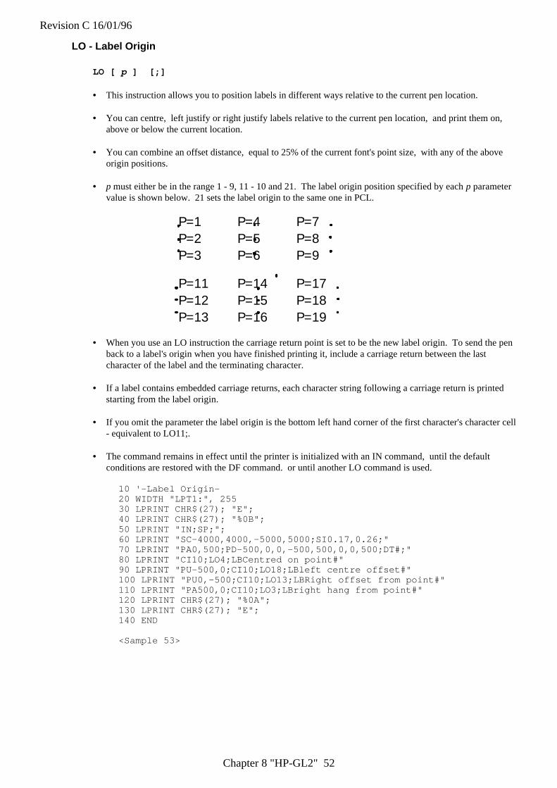
Revision C 16/01/96
Chapter 8 "HP-GL2" 52
LO - Label Origin
LO [ p ] [;]
• This instruction allows you to position labels in different ways relative to the current pen location.
• You can centre, left justify or right justify labels relative to the current pen location, and print them on,above or below the current location.
• You can combine an offset distance, equal to 25% of the current font's point size, with any of the aboveorigin positions.
• p must either be in the range 1 - 9, 11 - 10 and 21. The label origin position specified by each p parametervalue is shown below. 21 sets the label origin to the same one in PCL.
P=1 P=4 P=7P=2 P=5 P=8P=3 P=6 P=9
P=11 P=14 P=17P=12 P=15 P=18P=13 P=16 P=19
• When you use an LO instruction the carriage return point is set to be the new label origin. To send the penback to a label's origin when you have finished printing it, include a carriage return between the lastcharacter of the label and the terminating character.
• If a label contains embedded carriage returns, each character string following a carriage return is printedstarting from the label origin.
• If you omit the parameter the label origin is the bottom left hand corner of the first character's character cell- equivalent to LO11;.
• The command remains in effect until the printer is initialized with an IN command, until the defaultconditions are restored with the DF command. or until another LO command is used.
10 '-Label Origin-20 WIDTH "LPT1:", 25530 LPRINT CHR$(27); "E";40 LPRINT CHR$(27); "%0B";50 LPRINT "IN;SP;";60 LPRINT "SC-4000,4000,-5000,5000;SI0.17,0.26;"70 LPRINT "PA0,500;PD-500,0,0,-500,500,0,0,500;DT#;"80 LPRINT "CI10;LO4;LBCentred on point#"90 LPRINT "PU-500,0;CI10;LO18;LBleft centre offset#"100 LPRINT "PU0,-500;CI10;LO13;LBRight offset from point#"110 LPRINT "PA500,0;CI10;LO3;LBright hang from point#"120 LPRINT CHR$(27); "%0A";130 LPRINT CHR$(27); "E";140 END
<Sample 53>

Revision C 16/01/96
Chapter 8 "HP-GL2" 53
DI - Absolute Direction
DI [ run , rise ] [;]
run : X direction componentrise : Y direction component
• This command determines the direction in which subsequent labels will be printed.
• riserun gives the tangent of the angle between the base line of a label's characters and the horizontal.
• run is equivalent to cos θ and rise is equivalent to sin θ.
θrun
risetan θ = cos
sinθθ
• Values for run and rise are clamped real numbers.
• When you issue a DI instruction the carriage return point is set to the current pen location.
• The instruction is ignored if run and rise are both 0.
• Any text path that you set with the DV instruction will combine with the current printing direction todetermine the layout of characters on the page.
• If you omit the parameters the printing direction is horizontal.
• The label direction which is specified by this command is not affected by changes in the location of P1 andP2.
10 ' -Absolute Direction -20 WIDTH "LPT1:", 25530 LPRINT CHR$(27); "E";40 LPRINT CHR$(27); "%0B";50 LPRINT "IN;SP1;";60 DEG = -4570 RAD = 3.1416 / 180 * DEG80 LPRINT "IN;SP2;PA3050,4450;"90 LPRINT "DT";"100 LPRINT "DT0,2;LB_*_1988#"; "DI2,2;LB_*_1989#";110 LPRINT "DT2,0;LB_*_1990#"; "DI2,-2;LB_*_1991#";120 LPRINT "DT0,-2;LB_*_1992#"; "DI-2,-2;LB_*_1993#";130 LPRINT "DT-2,0;LB_*_1994#"; "DI-2,2;LB_*_1995#";140 LPRINT "PA3500,5350;DI", COS(0),SIN(0); "LB_*_2000"; CHR$(13); "#";150 LPRINT "DI", COS(RAD); SIN(RAD); "LB_RETURN POINT"; CHR$(13); "#";160 LPRINT CHR$(27); "%0A";170 LPRINT CHR$(27); "E";180 END
<sample 54>

Revision C 16/01/96
Chapter 8 "HP-GL2" 54
DR - Relative Direction
DR [ run , rise ] [;]
run : X-component of the printing direction expressed as a percentage of the x-component of thedistance between P1 and P2.
rise : Y-component of the printing direction expressed as a percentage of the y-component of thedistance between P1 and P2.
• • This command determines the direction in which subsequent labels will be printed.
• Values for run and rise are clamped real numbers.
• The instruction is ignored if run and rise are both 0.
• When you issue a DR instruction the carriage return point is set to the current pen location.
• Any text path that you set with the DV instruction will combine with the current printing directiondetermine the layout of characters on the page.
• If you change the positions of P1 and P2 the printing direction will change accordingly.
• If you omit the parameters the printing direction is horizontal and the run = 1% of |P2X-P1X|.
• Actual values for run and rise are changed relative to the P1 and P2 value. It is calculated as below:
actual run = run parameter ÷ 100 x (P2x - P1x)actual rise = rise parameter ÷ 100 x (P2y - P1y)
θrun=70%
rise = 60%
(70,0)
(0,60)
(0, 100)
(0, 100)
(100, 100)

Revision C 16/01/96
Chapter 8 "HP-GL2" 55
DV - Define Variable Text Path
DV [ path [, line ]] [;]
path : text printing path - horizontal or vertical, and left to right, right to left, upwards or downwards.line: the effect of a line feed.
� This command determines the printing direction for labels and the carriage return point.
� Permissible values of path are 0, 1, 2 and 3. If path = 0 labels are printed horizontally and left toright - normal printing. If path = 1 labels are printed vertically downwards - characters appear in avertical column. If path = 2 labels are printed horizontally and right to left - words appearbackwards. If path = 3 labels are printed vertically upwards - characters appear in a vertical column,reading from bottom to top.
� The value of line must be either 0 or 1. If line = 0, each time a line feed is encountered the currentpen position is moved at an angle of 90° to the path in a clockwise direction. Hence, if path = 1 thesecond line of text is printed to the left of the first line. If line = 1 each time a line feed isencountered the current pen position is moved at an angle of 90° to the path in an anticlockwisedirection. Hence, if path = 2 the second line of text is printed below the first line.
� If you do not use a DV command the default text path is horizontal, left to right: line feeds willmove the pen position at 90° to the text clockwise. This is equivalent to using the command DV0,0;
� If you omit both parameters the text path is horizontal, left to right.
Revision C 16/01/96
Chapter 8 "HP-GL2" 56
CP - Relative Character Movement
CP [ spaces [,lines]] [;]
spaces ; the number of text spaces the pen position is moved.lines ; the number of text lines the pen position is moved.
• Use this command to re-position the pen. The command moves the pen the specified number of lines andspaces corresponding to the currently selected font's pitch and line spacing. (For proportionally spacedfonts the width of the space character is used to determine the distance moved horizontally). All movementis relative to the current label printing direction.
• spaces is the number of spaces that the pen moves. A positive value of spaces moves the pen right from thecurrent pen location: a negative value moves it to the left.
• lines is the number of lines that the pen moves. A negative value offset moves the pen down from thecurrent pen location: a positive value moves it upwards.
• Values for spaces and lines are clamped real numbers.
• The command only moves the pen and does not draw lines, irrespective of whether the pen is currently upor down.
• On completion of the command, the previous pen status (up or down) is restored.
• The height of text lines (the vertical distance that a line feed moves the pen position) is fixed for every font.However, it can be adjusted using the ES instruction.
• If you omit all parameters, the pen position moves to the carriage return point and then down one line -hence CP; is equivalent to a carriage return followed by a line feed.
10 '-Character Plot -20 WIDTH "LPT1:", 25530 LPRINT CHR$(27); "E";40 LPRINT CHR$(27); "%0B";50 LPRINT "IN;SP1;";60 LPRINT "PA1000,5000;";70 LPRINT "PD;PR2000,0;PU;";80 LPRINT "CP-15,1;";90 LPRINT "LBAbove the line"; CHR$(3);100 LPRINT "CP-14,-2;";110 LPRINT "LBBelow the line"; CHR$(3);120 LPRINT CHR$(27); "%0A";130 LPRINT CHR$(27); "E";140 END
<Sample 55>
Revision C 16/01/96
Chapter 8 "HP-GL2" 57
CF - Character Fill Mode
CF [ fill [, pen ]] [;]
fill : the fill pattern used to fill characterspen : the pen used to edge characters
� This command determines how characters are edged and filled.
� Only scalable fonts can be both filled and edged - bitmap fonts and the stick font cannot be edgedand can only be filled with raster fill, shading or PCL cross-hatch patterns. Scalable characters canbe filled with any pattern specified by the FT command.
� Permissible values of fill are 0, 1, 2 and 3. If fill = 0 characters are filled with a solid fill and edged.If fill = 1 characters are edged but not filled. (Bitmap characters and stick font characters are filledas they cannot be edged.) If fill = 2 characters are filled using the current fill type, but not edged. Iffill = 3 characters are filled, using the current fill type, and edged.
� pen can be either 0 or 1. A value of 0 specifies the edging pen to be white; a value of 1 selects theblack pen for edging. If no pen is specified in the instruction the current pen, as selected with theSP command, is used.
� The width of the edging pen is proportional to the character's point size.
� The fill line width used for cross hatch patterns is set with the PW command.
� If you omit both parameters, solid fill and the white edging pen are selected - this is equivalent toCF0.0;
� If the command is not used all characters are solid and unedged.
� A CF command remains in effect until an IN command is used to initialize the printer, a DFcommand is used to restore the default settings, or another CF command is invoked.
10 '-Character Fill Mode -20 WIDTH "LPT1:", 25530 LPRINT CHR$(27); "E";40 LPRINT CHR$(27); "%0B";50 LPRINT "IN;SP1;";60 LPRINT "SD1,21,2,1,4,140,5,0,6,3,7,52;SS;"70 LPRINT "PA1000,3000;DT*;FT3,50,45;"80 LPRINT "CF1,1;LBA*;"90 LPRINT "PW0.1;CF3,1;LBB*;"100 LPRINT "PW0.5;LBC*;"110 LPRINT CHR$(27); "%0A";120 LPRINT CHR$(27); "E";130 END
<sample 56>

Revision C 16/01/96
Chapter 8 "HP-GL2" 58
SI - Set Absolute Character Size
SI [ width , height ] [;]
width : the width in centimeters of printed charactersheight : the height in centimeters of printed characters
• This command allows you to specify the size of the characters that you print with the LB instruction incentimeters.
• width specifies character width and is a clamped real number. Negative values of width produce right-to-left mirror image characters.
• height specifies the height of a capital letter and is a clamped real number. Negative values of heightproduce upside-down mirror image characters.
• If you change character size, the line width used to draw stick font characters may also change.
• If you omit the parameters, the character size is as specified by the most recent SD or AD command.
• If an SB1; command has previously been issued, printed characters may not be exactly the size that youspecify.
• If an SB1; command has been issued, specifying a negative value will not produce mirror image characters.
10 ' -Absolute Character Size-20 WIDTH "LPT1:", 25530 LPRINT CHR$(27); "E";40 LPRINT CHR$(27); "%0B";50 LPRINT "IN;SP1;";60 LPRINT "PA700,3000;DT#;LBPrinter#"70 LPRINT "PA700,2000;SI0.75,1;LBPrinter#"80 LPRINT "SI;SD1,21,2,1,3,12,5,0,6,0,7,52;SS;"90 LPRINT "PA40003000;LBPrinter#"100 LPRINT "PA4000,2000;SI1,1.5;LBPrinter#"110 LPRINT CHR$(27); "%0A";120 LPRINT CHR$(27); "E";130 END
<Sample 57>
Revision C 16/01/96
Chapter 8 "HP-GL2" 59
SR - Set Relative Character Size
SR [ width , height ] [;]
width ; the width of printed characters expressed as a percentage of the x-component of the distance betweenP1 and P2.
height ; the height of printed characters expressed as a percentage of the y-component of the distancebetween P1 and P2.
• This command allows you to specify the size of the character that you print with the LB instruction, relativeto the scaling points P1 and P2.
• width sets the character width to a percentage of |P2x-P1x| and is a clamped real number. Negative valuesof width produce right-to-left mirror image characters
• height sets the character height to a percentage of |P2y-P2y| and is a clamped real number. Negative valuesof height produce upside-down mirror image character.
• If you change the positions of P1 and P2, the character size will change unless the scaling points remain inthe same relative positions.
• If you move P2 to the left of, or below P1, characters will appear in mirror image.
• If you change the character size, the line width used to draw stick font characters may also change.
• If you omit the parameters, the character size is as specified by the most recent SD or AD command.
10 '-Relative Character Size-20 WIDTH "LPT1:", 25530 LPRINT CHR$(27); "E";40 LPRINT CHR$(27); "%0B";50 LPRINT "IN;SP1;";60 LPRINT "IP2000,2000,6500,6500;DT@;"70 LPRINT "SR;PA0,2700;LBRELATIVE LABEL SIZE@"80 LPRINT "IP0,0,5500,5500;PA0,2000;"90 LPRINT "LBNEW P1 AND P2 CHANGE LABEL SIZE@"100 LPRINT "PA0,1000;SR2.5;LBNEW SR INSTRUCTION`;CP;"110 LPRINT CHR$(27); "%0A";120 LPRINT CHR$(27); "E";140 END
<Sample 58>
Revision C 16/01/96
Chapter 8 "HP-GL2" 60
SL - Character Slant
SL [ tan φφ ] [;]
tan φ - tangent of character slant angle (φ)
• This command determines the slant of characters printed with subsequent LB commands.
• φ is the angle between characters and the vertical. A positive value of φ ( and tan φ ) produces forwardsloping characters, while a negative value results in characters which slant backwards.
• Values of tan φ are clamped real numbers.
• A value of 0 for tan φ results in upright characters.
• If you omit the parameter, tan φ is take to be 0 and any characters printed will be upright.
10 ' -Character Slant-20 WIDTH "LPT1:", 25530 LPRINT CHR$(27); "E";40 LPRINT CHR$(27; "%0B";50 LPRINT "IN;SP1;";60 LPRINT "SD1,21,2,1,4,25,5,0,6,0,7,5;SI0.7,1;"70 LPRINT "PA1000,1000;DT#,1;SL0.36,LBPrinter#"80 LPRINT "PA1000,300;SL-0.36;LBPrinter#"90 LPRINT CHR$(27); "%0A";100 LPRINT CHR$(27); "E";110 END
<Sample 59>
SB - Scalable or Bitmap Fonts
SB [ n ] [;]
n : font category selection
• This command enables you to restrict the range of selectable fonts to scalable fonts and the stick font only.
• n can be 0 or 1. If n = 0 you may only select scalable fonts (or the stick font). If n = 1 you may select anytype of font.
• An SB command can alter the current standard and alternate font selections.
• Setting n to 1 allows the selection of bitmapped fonts and has the following side-effects:
• Bitmap characters cannot be edged.
• Bitmap characters can only be printed in orientations of 0°, 90°, 180° or 270°.
• The SL (character slant) command is not applied to bitmap fonts.
• Bitmap font character sizes are approximate only.
• The DF and IN commands set n to 0, - only scalable fonts and the stick fonts may be selected.
• The FI and FN commands implicitly set n to 1 if you use either of them to select a bitmap font.
• If you omit n from the command, only scalable fonts and the stick font may be selected. This is equivalentto an SB0; command.
• The default setting is scalable fonts and stick font only.
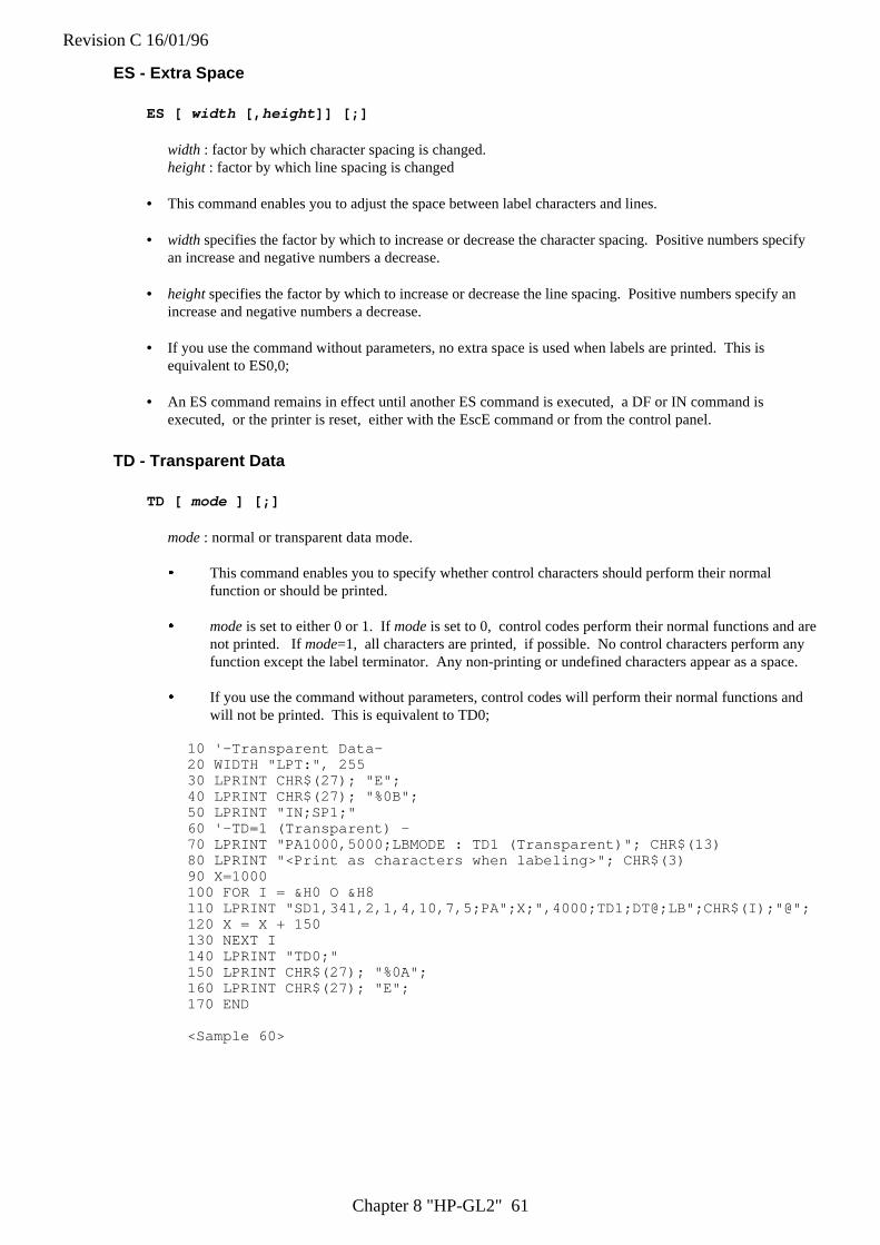
Revision C 16/01/96
Chapter 8 "HP-GL2" 61
ES - Extra Space
ES [ width [, height ]] [;]
width : factor by which character spacing is changed.height : factor by which line spacing is changed
• This command enables you to adjust the space between label characters and lines.
• width specifies the factor by which to increase or decrease the character spacing. Positive numbers specifyan increase and negative numbers a decrease.
• height specifies the factor by which to increase or decrease the line spacing. Positive numbers specify anincrease and negative numbers a decrease.
• If you use the command without parameters, no extra space is used when labels are printed. This isequivalent to ES0,0;
• An ES command remains in effect until another ES command is executed, a DF or IN command isexecuted, or the printer is reset, either with the EscE command or from the control panel.
TD - Transparent Data
TD [ mode ] [;]
mode : normal or transparent data mode.
� This command enables you to specify whether control characters should perform their normalfunction or should be printed.
� mode is set to either 0 or 1. If mode is set to 0, control codes perform their normal functions and arenot printed. If mode=1, all characters are printed, if possible. No control characters perform anyfunction except the label terminator. Any non-printing or undefined characters appear as a space.
� If you use the command without parameters, control codes will perform their normal functions andwill not be printed. This is equivalent to TD0;
10 '-Transparent Data-20 WIDTH "LPT:", 25530 LPRINT CHR$(27); "E";40 LPRINT CHR$(27); "%0B";50 LPRINT "IN;SP1;"60 '-TD=1 (Transparent) -70 LPRINT "PA1000,5000;LBMODE : TD1 (Transparent)"; CHR$(13)80 LPRINT "<Print as characters when labeling>"; CHR$(3)90 X=1000100 FOR I = &H0 O &H8110 LPRINT "SD1,341,2,1,4,10,7,5;PA";X;",4000;TD1;DT@;LB";CHR$(I);"@";120 X = X + 150130 NEXT I140 LPRINT "TD0;"150 LPRINT CHR$(27); "%0A";160 LPRINT CHR$(27); "E";170 END
<Sample 60>
Revision C 16/01/96
Chapter 9 "HP-GL" 1
CHAPTER 9
HP-GL
Graphics Language
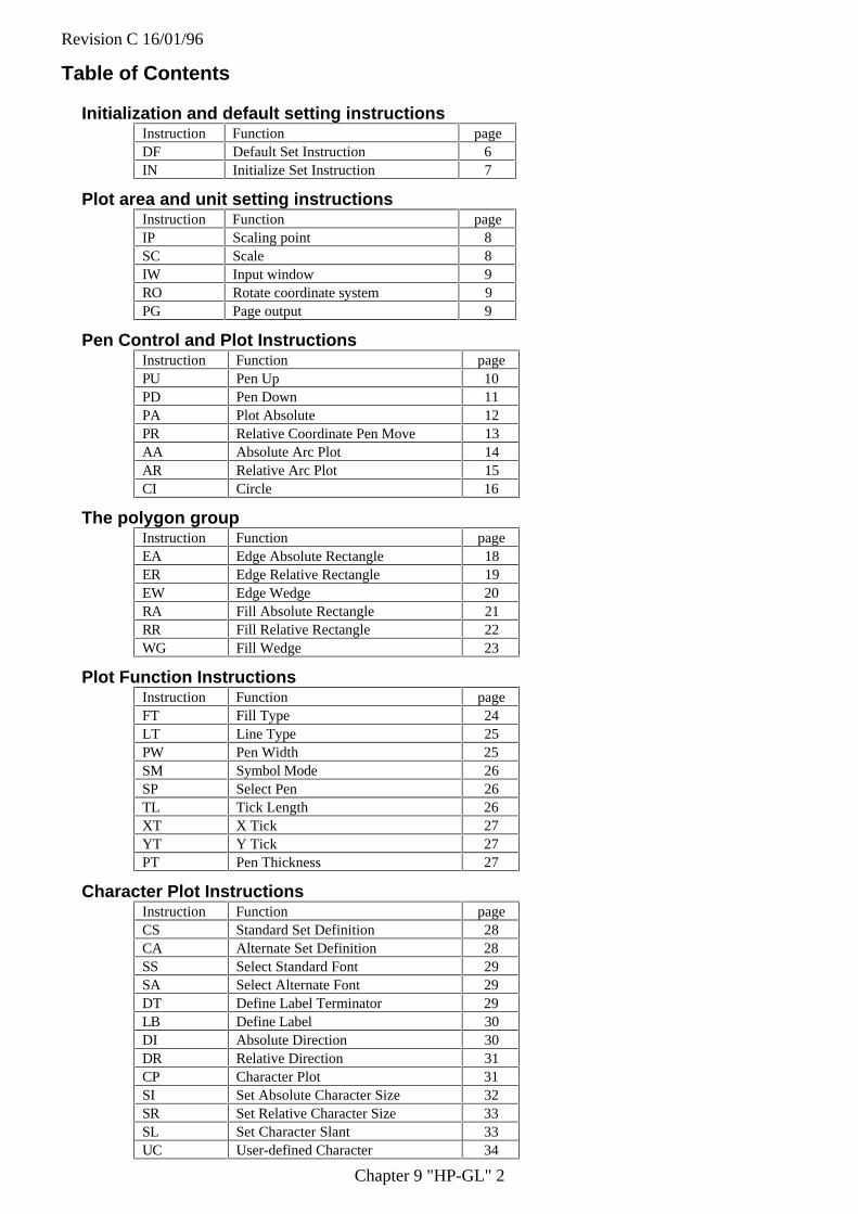
Revision C 16/01/96
Chapter 9 "HP-GL" 2
Table of Contents
Initialization and default setting instructionsInstruction Function pageDF Default Set Instruction 6IN Initialize Set Instruction 7
Plot area and unit setting instructionsInstruction Function pageIP Scaling point 8SC Scale 8IW Input window 9RO Rotate coordinate system 9PG Page output 9
Pen Control and Plot InstructionsInstruction Function pagePU Pen Up 10PD Pen Down 11PA Plot Absolute 12PR Relative Coordinate Pen Move 13AA Absolute Arc Plot 14AR Relative Arc Plot 15CI Circle 16
The polygon groupInstruction Function pageEA Edge Absolute Rectangle 18ER Edge Relative Rectangle 19EW Edge Wedge 20RA Fill Absolute Rectangle 21RR Fill Relative Rectangle 22WG Fill Wedge 23
Plot Function InstructionsInstruction Function pageFT Fill Type 24LT Line Type 25PW Pen Width 25SM Symbol Mode 26SP Select Pen 26TL Tick Length 26XT X Tick 27YT Y Tick 27PT Pen Thickness 27
Character Plot InstructionsInstruction Function pageCS Standard Set Definition 28CA Alternate Set Definition 28SS Select Standard Font 29SA Select Alternate Font 29DT Define Label Terminator 29LB Define Label 30DI Absolute Direction 30DR Relative Direction 31CP Character Plot 31SI Set Absolute Character Size 32SR Set Relative Character Size 33SL Set Character Slant 33UC User-defined Character 34
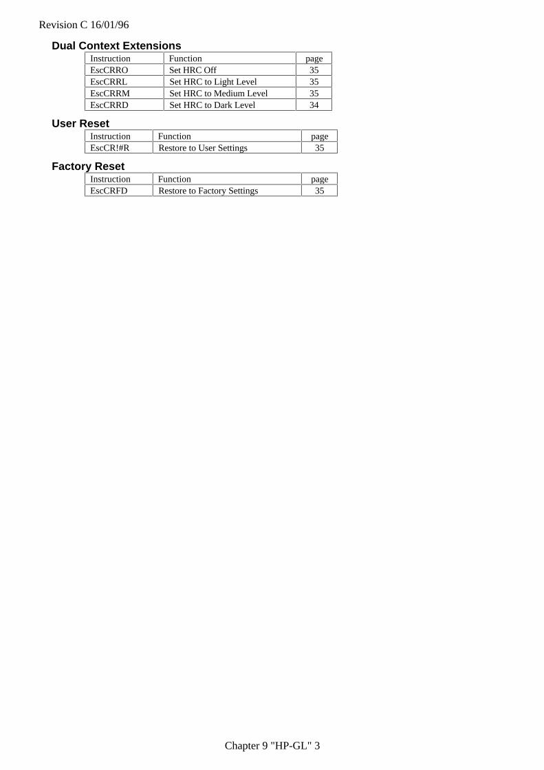
Revision C 16/01/96
Chapter 9 "HP-GL" 3
Dual Context ExtensionsInstruction Function pageEscCRRO Set HRC Off 35EscCRRL Set HRC to Light Level 35EscCRRM Set HRC to Medium Level 35EscCRRD Set HRC to Dark Level 34
User ResetInstruction Function pageEscCR!#R Restore to User Settings 35
Factory ResetInstruction Function pageEscCRFD Restore to Factory Settings 35
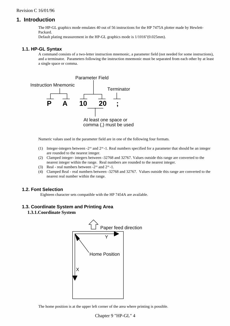
Revision C 16/01/96
Chapter 9 "HP-GL" 4
1. IntroductionThe HP-GL graphics mode emulates 40 out of 56 instructions for the HP 7475A plotter made by Hewlett-Packard.Default plating measurement in the HP-GL graphics mode is 1/1016"(0.025mm).
1.1. HP-GL SyntaxA command consists of a two-letter instruction mnemonic, a parameter field (not needed for some instructions),and a terminator. Parameters following the instruction mnemonic must be separated from each other by at leasta single space or comma.
P A 10 20 ;
Instruction Mnemonic
Parameter Field
Terminator
At least one space orcomma (,) must be used
Numeric values used in the parameter field are in one of the following four formats.
(1) Integer-integers between -230 and 230 -1. Real numbers specified for a parameter that should be an integerare rounded to the nearest integer.
(2) Clamped integer- integers between -32768 and 32767. Values outside this range are converted to thenearest integer within the range. Real numbers are rounded to the nearest integer.
(3) Real - real numbers between -230 and 230 -1.(4) Clamped Real - real numbers between -32768 and 32767. Values outside this range are converted to the
nearest real number within the range.
1.2. Font Selection Eighteen character sets compatible with the HP 7454A are available.
1.3. Coordinate System and Printing Area1.3.1.Coordinate System
Paper feed direction
X
Y
Home Position
The home position is at the upper left corner of the area where printing is possible.
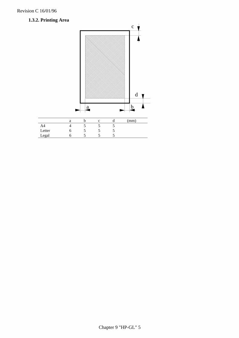
Revision C 16/01/96
Chapter 9 "HP-GL" 5
1.3.2. Printing Area
a b
d
c
a b c d (mm)A4 4 5 5 5Letter 6 5 5 5Legal 6 5 5 5
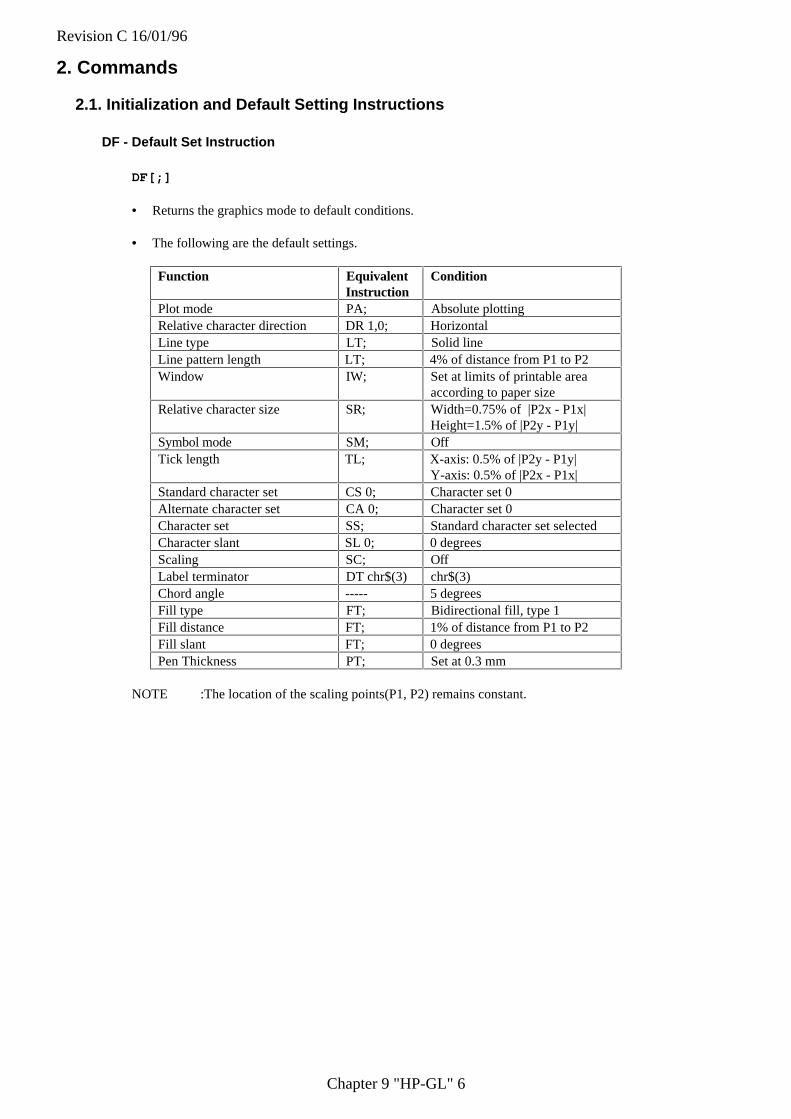
Revision C 16/01/96
Chapter 9 "HP-GL" 6
2. Commands
2.1. Initialization and Default Setting Instructions
DF - Default Set Instruction
DF[;]
• Returns the graphics mode to default conditions.
• The following are the default settings.
Function EquivalentInstruction
Condition
Plot mode PA; Absolute plottingRelative character direction DR 1,0; HorizontalLine type LT; Solid lineLine pattern length LT; 4% of distance from P1 to P2Window IW; Set at limits of printable area
according to paper sizeRelative character size SR; Width=0.75% of |P2x - P1x|
Height=1.5% of |P2y - P1y|Symbol mode SM; OffTick length TL; X-axis: 0.5% of |P2y - P1y|
Y-axis: 0.5% of |P2x - P1x|Standard character set CS 0; Character set 0Alternate character set CA 0; Character set 0Character set SS; Standard character set selectedCharacter slant SL 0; 0 degreesScaling SC; OffLabel terminator DT chr$(3) chr$(3)Chord angle ----- 5 degreesFill type FT; Bidirectional fill, type 1Fill distance FT; 1% of distance from P1 to P2Fill slant FT; 0 degreesPen Thickness PT; Set at 0.3 mm
NOTE :The location of the scaling points(P1, P2) remains constant.
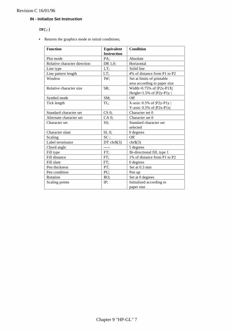
Revision C 16/01/96
Chapter 9 "HP-GL" 7
IN - Initialize Set Instruction
IN[;]
• Returns the graphics mode to initial conditions;
Function EquivalentInstruction
Condition
Plot mode PA; AbsoluteRelative character direction DR 1,0; HorizontalLine type LT; Solid lineLine pattern length LT; 4% of distance from P1 to P2Window IW; Set at limits of printable
area according to paper sizeRelative character size SR; Width=0.75% of |P2x-P1X|
Height=1.5% of |P2y-P1y |Symbol mode SM; OffTick length TL; X-axis: 0.5% of |P2y-P1y |
Y-axis: 0.5% of |P2x-P1x|Standard character set CS 0; Character set 0Alternate character set CA 0; Character set 0Character set SS; Standard character set
selectedCharacter slant SL 0; 0 degreesScaling SC ; OffLabel terminator DT chr$(3) chr$(3)Chord angle ----- 5 degreesFill type FT; Bi-directional fill, type 1Fill distance FT; 1% of distance from P1 to P2Fill slant FT; 0 degreesPen thickness PT; Set at 0.3 mmPen condition PU; Pen upRotation RO; Set at 0 degreesScaling points IP; Initialized according to
paper size
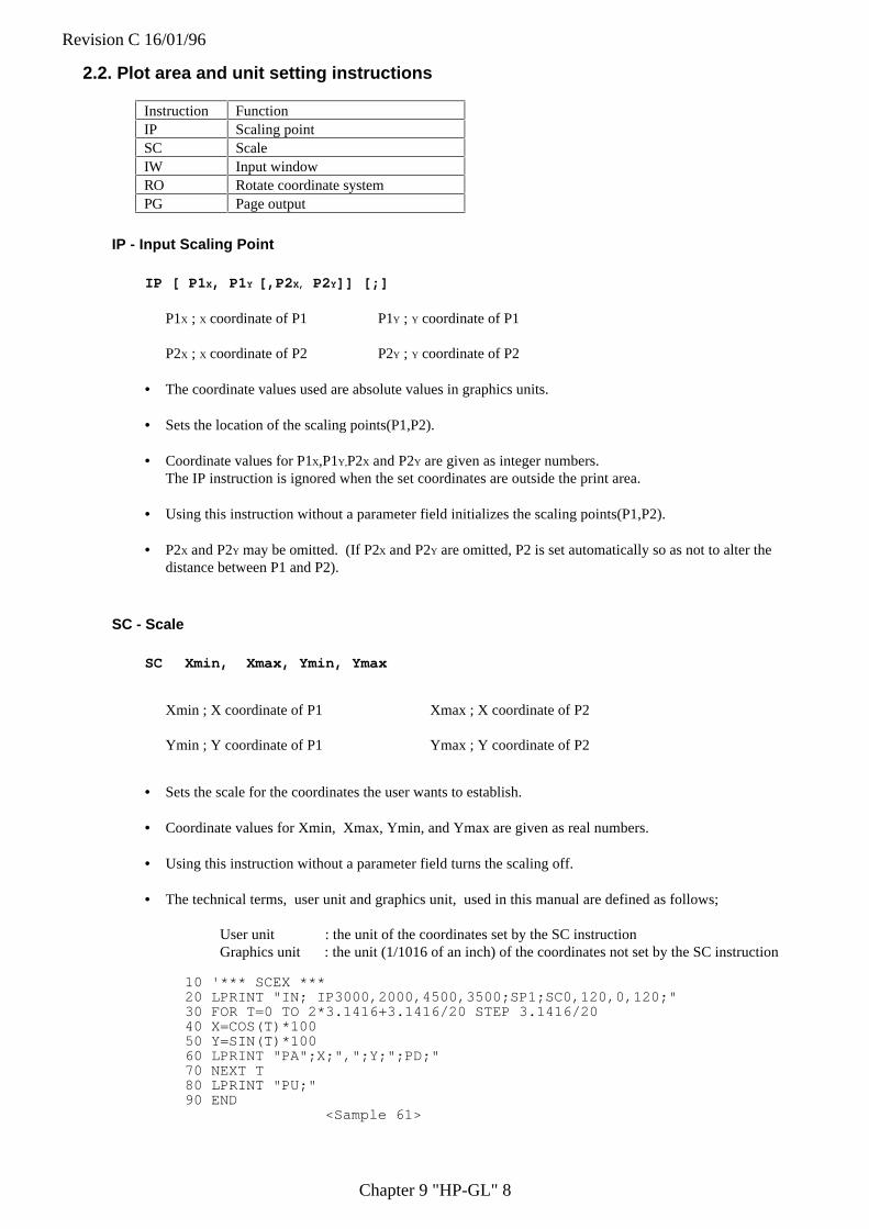
Revision C 16/01/96
Chapter 9 "HP-GL" 8
2.2. Plot area and unit setting instructions
Instruction FunctionIP Scaling pointSC ScaleIW Input windowRO Rotate coordinate systemPG Page output
IP - Input Scaling Point
IP [ P1 X, P1 Y [,P2 X, P2 Y]] [;]
P1X ; X coordinate of P1 P1Y ; Y coordinate of P1
P2X ; X coordinate of P2 P2Y ; Y coordinate of P2
• The coordinate values used are absolute values in graphics units.
• Sets the location of the scaling points(P1,P2).
• Coordinate values for P1X,P1Y,P2X and P2Y are given as integer numbers.The IP instruction is ignored when the set coordinates are outside the print area.
• Using this instruction without a parameter field initializes the scaling points(P1,P2).
• P2X and P2Y may be omitted. (If P2X and P2Y are omitted, P2 is set automatically so as not to alter thedistance between P1 and P2).
SC - Scale
SC Xmin, Xmax, Ymin, Ymax
Xmin ; X coordinate of P1 Xmax ; X coordinate of P2
Ymin ; Y coordinate of P1 Ymax ; Y coordinate of P2
• Sets the scale for the coordinates the user wants to establish.
• Coordinate values for Xmin, Xmax, Ymin, and Ymax are given as real numbers.
• Using this instruction without a parameter field turns the scaling off.
• The technical terms, user unit and graphics unit, used in this manual are defined as follows;
User unit : the unit of the coordinates set by the SC instructionGraphics unit : the unit (1/1016 of an inch) of the coordinates not set by the SC instruction
10 '*** SCEX ***20 LPRINT "IN; IP3000,2000,4500,3500;SP1;SC0,120,0,120;"30 FOR T=0 TO 2*3.1416+3.1416/20 STEP 3.1416/2040 X=COS(T)*10050 Y=SIN(T)*10060 LPRINT "PA";X;",";Y;";PD;"70 NEXT T80 LPRINT "PU;"90 END
<Sample 61>
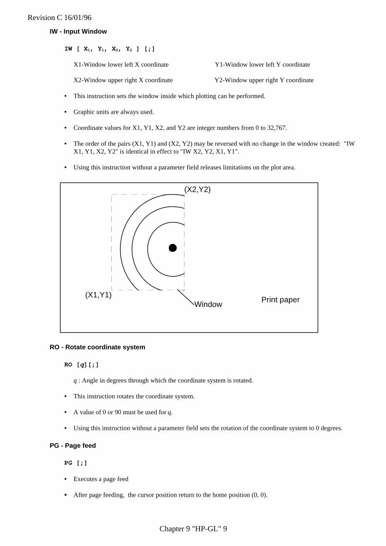
Revision C 16/01/96
Chapter 9 "HP-GL" 9
IW - Input Window
IW [ X 1, Y 1, X 2, Y 2 ] [;]
X1-Window lower left X coordinate Y1-Window lower left Y coordinate
X2-Window upper right X coordinate Y2-Window upper right Y coordinate
• This instruction sets the window inside which plotting can be performed.
• Graphic units are always used.
• Coordinate values for X1, Y1, X2, and Y2 are integer numbers from 0 to 32,767.
• The order of the pairs (X1, Y1) and (X2, Y2) may be reversed with no change in the window created: "IWX1, Y1, X2, Y2" is identical in effect to "IW X2, Y2, X1, Y1".
• Using this instruction without a parameter field releases limitations on the plot area.
(X2,Y2)
(X1,Y1)Window
Print paper
RO - Rotate coordinate system
RO [ q][;]
q : Angle in degrees through which the coordinate system is rotated.
• This instruction rotates the coordinate system.
• A value of 0 or 90 must be used for q.
• Using this instruction without a parameter field sets the rotation of the coordinate system to 0 degrees.
PG - Page feed
PG [;]
• Executes a page feed
• • After page feeding, the cursor position return to the home position (0, 0).

Revision C 16/01/96
Chapter 9 "HP-GL" 10
2.3. Pen Control and Plot Instructions
Instruction FunctionPU Pen UpPD Pen DownPA Plot AbsolutePR Relative Coordinate Pen MoveAA Absolute Arc PlotAR Relative Arc PlotCI Circle
PU - Pen Up
PU [ X,Y [,...]] [;]
X ; X coordinate of the cursor movement destination
Y ; Y coordinate of the cursor movement destination
• X and Y are either relative or absolute, depending on whether a PA or a PR was the last plot commandexecuted. The absolute coordinates are set as default.
• Moves the cursor to the specified coordinates after raising the pen.
• Using this instruction without a parameter field raises the pen without changing the cursor position.
• When scaling is on, user coordinates are used.
• Also, when scaling has been performed, the values for X and Y are real numbers.
• When scaling is off graphics units are used.
• When there is no scaling, the coordinates values for X and Y are integer numbers.
Current position
(X1, Y1)
(X2,Y2)
(X3, Y3)
(Xn, Yn)
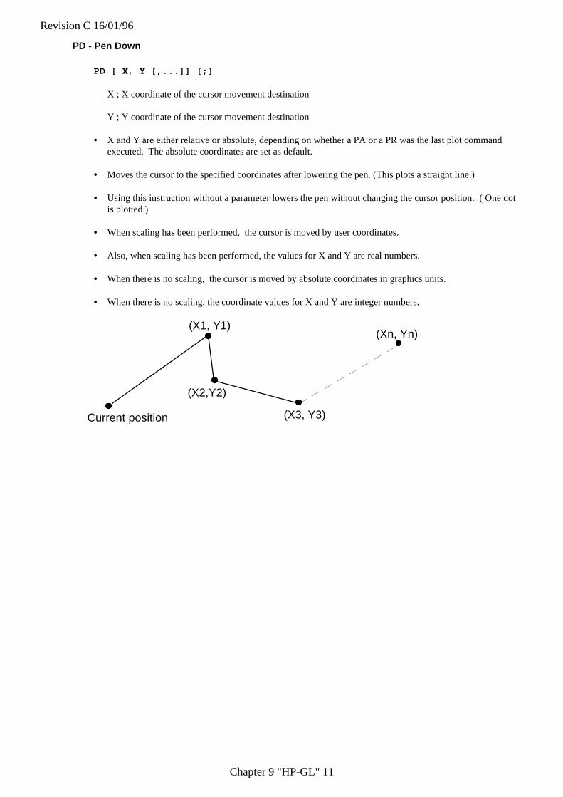
Revision C 16/01/96
Chapter 9 "HP-GL" 11
PD - Pen Down
PD [ X, Y [,...]] [;]
X ; X coordinate of the cursor movement destination
Y ; Y coordinate of the cursor movement destination
• X and Y are either relative or absolute, depending on whether a PA or a PR was the last plot commandexecuted. The absolute coordinates are set as default.
• Moves the cursor to the specified coordinates after lowering the pen. (This plots a straight line.)
• Using this instruction without a parameter lowers the pen without changing the cursor position. ( One dotis plotted.)
• When scaling has been performed, the cursor is moved by user coordinates.
• Also, when scaling has been performed, the values for X and Y are real numbers.
• When there is no scaling, the cursor is moved by absolute coordinates in graphics units.
• When there is no scaling, the coordinate values for X and Y are integer numbers.
Current position
(X1, Y1)
(X2,Y2)
(X3, Y3)
(Xn, Yn)

Revision C 16/01/96
Chapter 9 "HP-GL" 12
PA - Plot Absolute
PA [X, Y [,...]] [;]
X ; X coordinate of the cursor movement destination
Y ; Y coordinate of the cursor movement destination
• X and Y are absolute values in user units or graphics units.
• Moves the cursor to the specified coordinates.
• Plots a straight line only when the pen is down.
• When scaling has been performed, the values for X and Y are integer numbers.
• When there is no scaling, the cursor is moved by absolute coordinates in graphics units.
• When there is no scaling, the coordinate values for X and Y are integer numbers.
Current position
(X1, Y1)
(X2,Y2)
(X3, Y3)
(Xn, Yn)
10 '*** PAEX1 ***20 LPRINT "IN;SP1;"30 LPRINT "PA2000,6000;PD0,6000,2000,7500,2000,6000;PU2500,6000;"40 LPRINT "PAPD4500,6000,2500,7500,2500,6000;PU10365,500;"50 END
<Sample 62>
10 ' *** PAEX2 ***20 LPRINT "IN;SP1;SC0,100,0,100;"30 LPRINT "PA50,30;PD25,30,50,50,50,30;PU55,30;"40 LPRINT "PAPD80,30,55,50,55,30,PU;"50 END
<Sample 63>
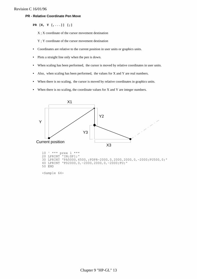
Revision C 16/01/96
Chapter 9 "HP-GL" 13
PR - Relative Coordinate Pen Move
PR [X, Y [,...]] [;]
X ; X coordinate of the cursor movement destination
Y ; Y coordinate of the cursor movement destination
• Coordinates are relative to the current position in user units or graphics units.
• Plots a straight line only when the pen is down.
• When scaling has been performed, the cursor is moved by relative coordinates in user units.
• Also, when scaling has been performed, the values for X and Y are real numbers.
• When there is no scaling, the cursor is moved by relative coordinates in graphics units.
• When there is no scaling, the coordinate values for X and Y are integer numbers.
Current position
Y
X1
Y2
Y3
X3
10 ' *** prex 1 ***20 LPRINT "IN;SP1;"30 LPRINT "PA5000,4500,;PDPR-2000,0,2000,2000,0,-2000;PU500,0;"40 LPRINT "PD2000,0,-2000,2000,0,-2000;PU;"50 END
<Sample 64>
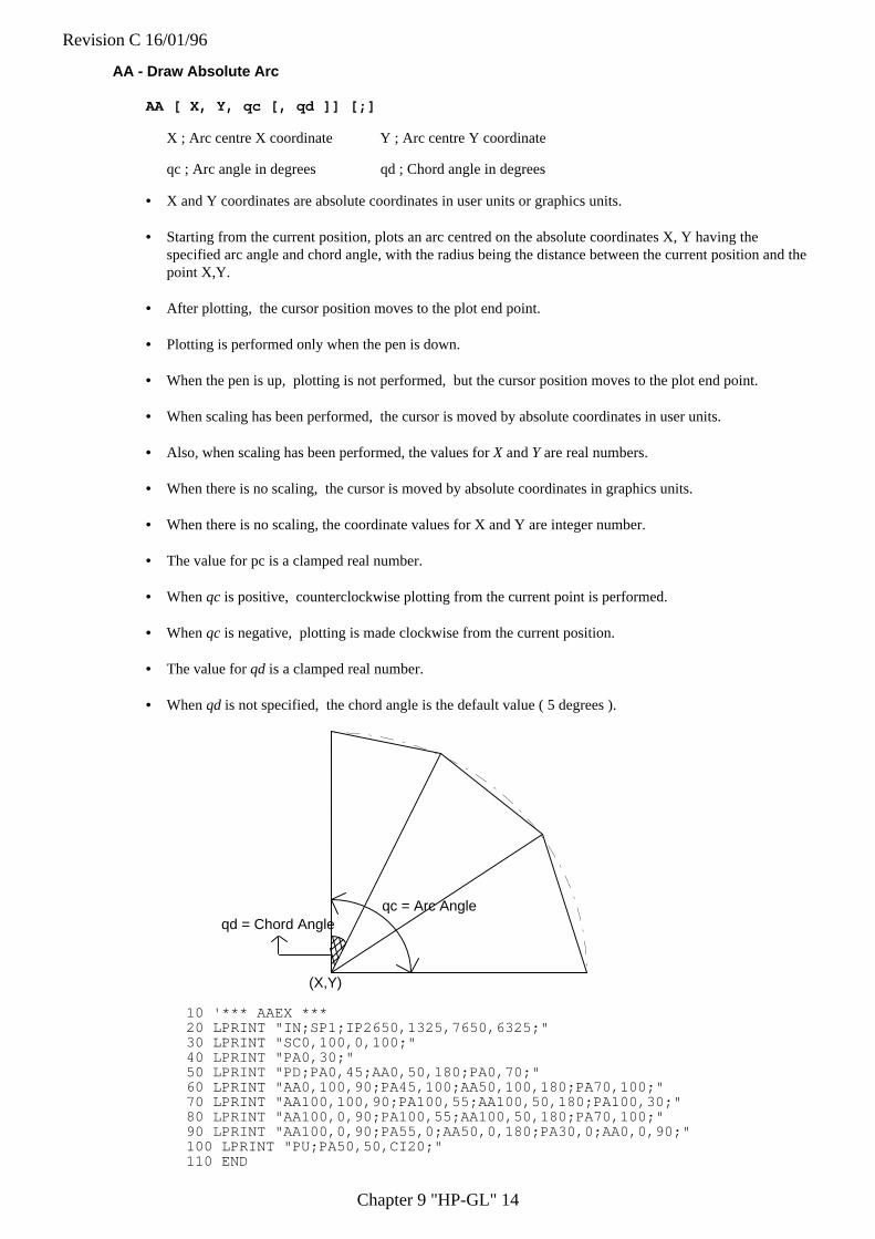
Revision C 16/01/96
Chapter 9 "HP-GL" 14
AA - Draw Absolute Arc
AA [ X, Y, qc [, qd ]] [;]
X ; Arc centre X coordinate Y ; Arc centre Y coordinate
qc ; Arc angle in degrees qd ; Chord angle in degrees
• X and Y coordinates are absolute coordinates in user units or graphics units.
• Starting from the current position, plots an arc centred on the absolute coordinates X, Y having thespecified arc angle and chord angle, with the radius being the distance between the current position and thepoint X,Y.
• After plotting, the cursor position moves to the plot end point.
• Plotting is performed only when the pen is down.
• When the pen is up, plotting is not performed, but the cursor position moves to the plot end point.
• When scaling has been performed, the cursor is moved by absolute coordinates in user units.
• Also, when scaling has been performed, the values for X and Y are real numbers.
• When there is no scaling, the cursor is moved by absolute coordinates in graphics units.
• When there is no scaling, the coordinate values for X and Y are integer number.
• The value for pc is a clamped real number.
• When qc is positive, counterclockwise plotting from the current point is performed.
• When qc is negative, plotting is made clockwise from the current position.
• The value for qd is a clamped real number.
• When qd is not specified, the chord angle is the default value ( 5 degrees ).
(X,Y)
qc = Arc Angleqd = Chord Angle
10 '*** AAEX ***20 LPRINT "IN;SP1;IP2650,1325,7650,6325;"30 LPRINT "SC0,100,0,100;"40 LPRINT "PA0,30;"50 LPRINT "PD;PA0,45;AA0,50,180;PA0,70;"60 LPRINT "AA0,100,90;PA45,100;AA50,100,180;PA70,100;"70 LPRINT "AA100,100,90;PA100,55;AA100,50,180;PA100,30;"80 LPRINT "AA100,0,90;PA100,55;AA100,50,180;PA70,100;"90 LPRINT "AA100,0,90;PA55,0;AA50,0,180;PA30,0;AA0,0,90;"100 LPRINT "PU;PA50,50,CI20;"110 END
Revision C 16/01/96
Chapter 9 "HP-GL" 15
<Sample 68>
Revision C 16/01/96
Chapter 9 "HP-GL" 16
AR - Draw Relative Arc
AR X, Y, qc(, qd)[;]
X ; Arc centre X coordinate Y ; Arc centre Y coordinate
qc ; Arc angle in degrees qd ; Chord angle in degrees
• X and Y coordinates are relative coordinates in user units or graphics units.
• Starting from the current cursor position the command plots an arc whose centre is at the relative coordinateposition (X,Y) and which has the specified arc and chord angles. The radius of the arc is the distancebetween the current position and the point (X,Y).
• After plotting the cursor position changes to the plot end point.
• Plotting is performed only when the pen is down.
• When the pen is up, plotting is not performed, but he cursor position moves to the plot end point.
• When scaling has been performed, the cursor is moved by relative coordinates in user units.
• Also, when scaling has been performed, the values for X and Y are real numbers.
• When there is no scaling, the cursor is moved by relative coordinates in graphics units.
• When there is no scaling, the coordinate values for X and Y are integer numbers.
• The value for qc is a clamped real number.
• When qc is positive, counterclockwise plotting from the current point is performed.
• When qc is negative, plotting is made clockwise from the current position.
• The value for qd is a clamped real number.
• When qd is not specified, the chord angle is the default value ( 5 degrees ).
10 '*** AREX1 ***20 LPRINT "IN;SP1;IP2650,1325,7650,6325;"30 LPRINT "SC-100,100,-100,100;"40 LPRINT "PA-80,-80;PD;AR0,50,90;AR50,0,90;PU;"50 END
<Sample 69>
10 ' *** AREX2 ***20 LPRINT "IN;SP1;IP2650,1325,7650,6325;"30 LPRINT "SC-100,100,-100,100;"40 LPRINT "PA-100,70;PD;PR30,0;AR-,-70,-90;AR70,0,90;PR60,0;PU;"50 END100 END
<Sample 70>
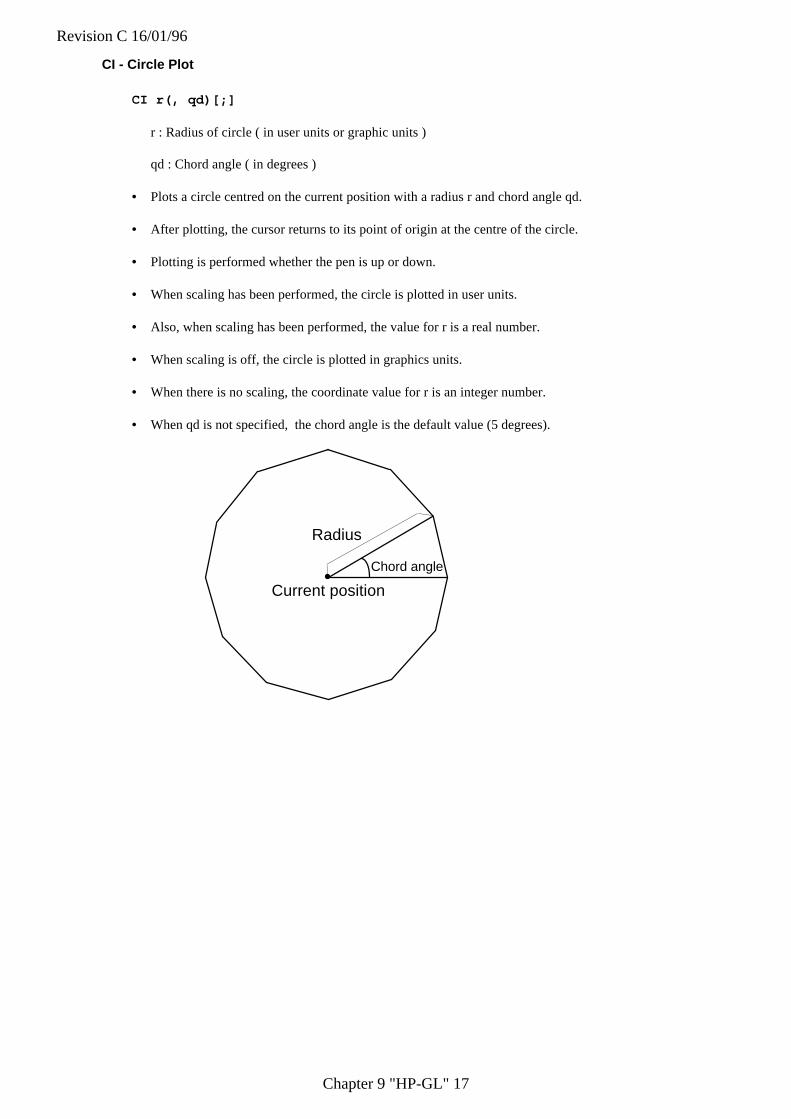
Revision C 16/01/96
Chapter 9 "HP-GL" 17
CI - Circle Plot
CI r(, qd)[;]
r : Radius of circle ( in user units or graphic units )
qd : Chord angle ( in degrees )
• Plots a circle centred on the current position with a radius r and chord angle qd.
• After plotting, the cursor returns to its point of origin at the centre of the circle.
• Plotting is performed whether the pen is up or down.
• When scaling has been performed, the circle is plotted in user units.
• Also, when scaling has been performed, the value for r is a real number.
• When scaling is off, the circle is plotted in graphics units.
• When there is no scaling, the coordinate value for r is an integer number.
• When qd is not specified, the chord angle is the default value (5 degrees).
Current position
Chord angle
Radius
Revision C 16/01/96
Chapter 9 "HP-GL" 18
10 '*** CIEX1 ***20 LPRINT "IN;SP1;IP2650,1325,7650,6325;"30 LPRINT "SC-100,100,-100,100;"40 LPRINT "PA-60,50;CI40,45;"50 LPRINT "PA60,50;CI40,30;"60 LPRINT "PA-60,-50;CI40,15;"70 LPRINT "PA60,-50;CI40,5;"80 END
<Sample 65>
10 '*** CIEX2 ***20 LPRINT "IN;SP1;IP2650,1325,8650,7325;"30 LPRINT "SC0,170,0,170;"40 LPRINT "PA100,100;LT;CI10,5;LT0;CI-20,5;LT1;CI30,5;"50 LPRINT "LT2;CI-40,5;LT3;CI50,5;LT4;CI-60,5;LT5;CI70,5;LT6;CI80,5;"60 END
<Sample 66>
10 '*** CIEX3 ***20 LPRINT "IN;SP1;IP2650,1325,7650,6325;"30 LPRINT "SC-1000,1000,-1000,1000;"40 LPRINT "PA-800,800;"50 GOSUB 13060 LPRINT "PA200,800;"70 GOSUB 13080 LPRINT "PA-800,-200;"90 GOSUB 130100 LPRINT"PA200,-200;"110 GOSUB 130120 END130 LPRINT "CI70;PR600,0;CI70;PR-300,-300;CI250;"140 LPRINT "PR-300,-300;CI70;PR600,0;CI70;"150 RETURN
<Sample 67>
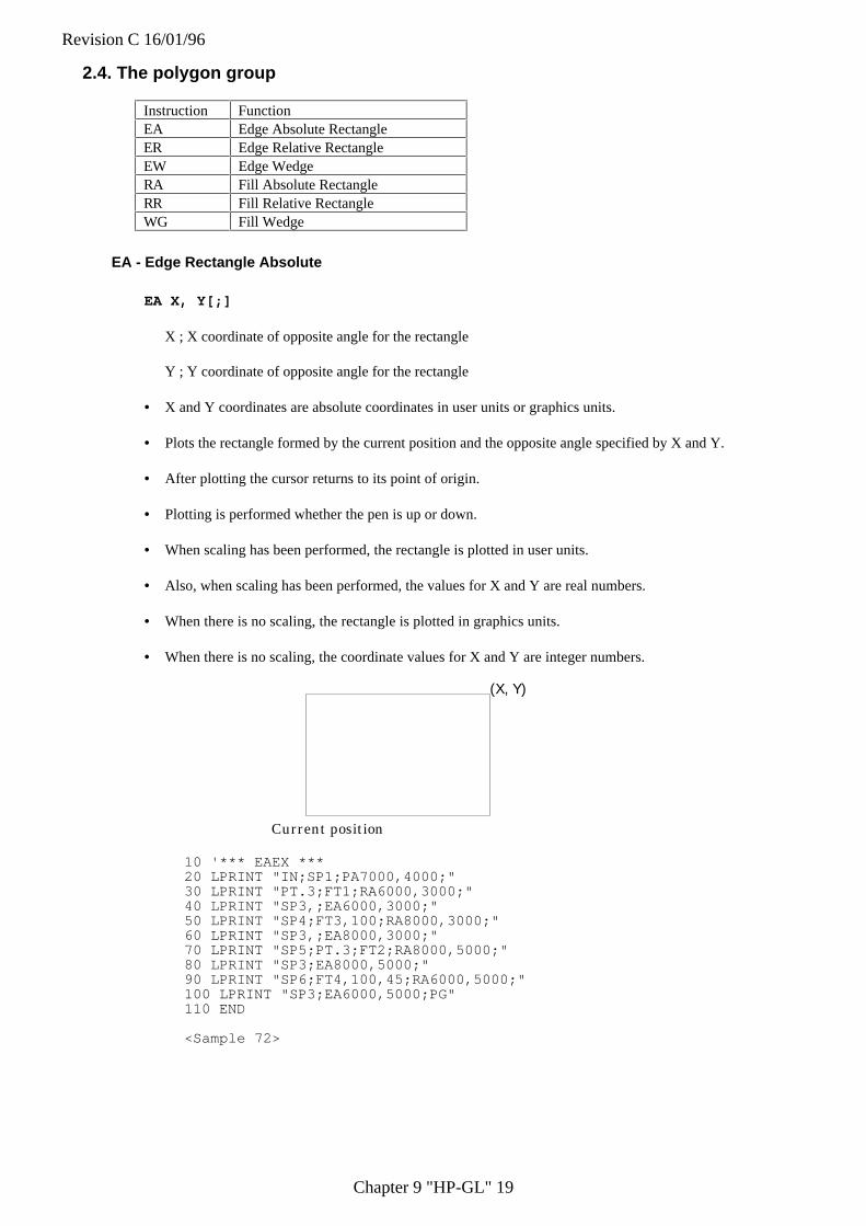
Revision C 16/01/96
Chapter 9 "HP-GL" 19
2.4. The polygon group
Instruction FunctionEA Edge Absolute RectangleER Edge Relative RectangleEW Edge WedgeRA Fill Absolute RectangleRR Fill Relative RectangleWG Fill Wedge
EA - Edge Rectangle Absolute
EA X, Y[;]
X ; X coordinate of opposite angle for the rectangle
Y ; Y coordinate of opposite angle for the rectangle
• X and Y coordinates are absolute coordinates in user units or graphics units.
• Plots the rectangle formed by the current position and the opposite angle specified by X and Y.
• After plotting the cursor returns to its point of origin.
• Plotting is performed whether the pen is up or down.
• When scaling has been performed, the rectangle is plotted in user units.
• Also, when scaling has been performed, the values for X and Y are real numbers.
• When there is no scaling, the rectangle is plotted in graphics units.
• When there is no scaling, the coordinate values for X and Y are integer numbers.
Current position
(X, Y)
10 '*** EAEX ***20 LPRINT "IN;SP1;PA7000,4000;"30 LPRINT "PT.3;FT1;RA6000,3000;"40 LPRINT "SP3,;EA6000,3000;"50 LPRINT "SP4;FT3,100;RA8000,3000;"60 LPRINT "SP3,;EA8000,3000;"70 LPRINT "SP5;PT.3;FT2;RA8000,5000;"80 LPRINT "SP3;EA8000,5000;"90 LPRINT "SP6;FT4,100,45;RA6000,5000;"100 LPRINT "SP3;EA6000,5000;PG"110 END
<Sample 72>
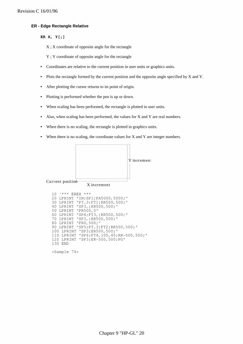
Revision C 16/01/96
Chapter 9 "HP-GL" 20
ER - Edge Rectangle Relative
ER X, Y[;]
X ; X coordinate of opposite angle for the rectangle
Y ; Y coordinate of opposite angle for the rectangle
• Coordinates are relative to the current position in user units or graphics units.
• Plots the rectangle formed by the current position and the opposite angle specified by X and Y.
• After plotting the cursor returns to its point of origin.
• Plotting is performed whether the pen is up or down.
• When scaling has been performed, the rectangle is plotted in user units.
• Also, when scaling has been performed, the values for X and Y are real numbers.
• When there is no scaling, the rectangle is plotted in graphics units.
• When there is no scaling, the coordinate values for X and Y are integer numbers.
Current position
Y increment
X increment
10 '*** EREX ***20 LPRINT "IN;SP1;PA5000,5000;"30 LPRINT "PT.3;FT1;RR500,500;"40 LPRINT "SP3,;ER500,500;"50 LPRINT "PR500,0"60 LPRINT "SP4;FT3,;RR500,500;"70 LPRINT "SP3,;ER500,500;"80 LPRINT "PR0,500;"90 LPRINT "SP5;PT.3;FT2;RR500,500;"100 LPRINT "SP3;ER500,500;"110 LPRINT "SP6;FT4,100,45;RR-500,500;"120 LPRINT "SP3;ER-500,500;PG"130 END
<Sample 74>
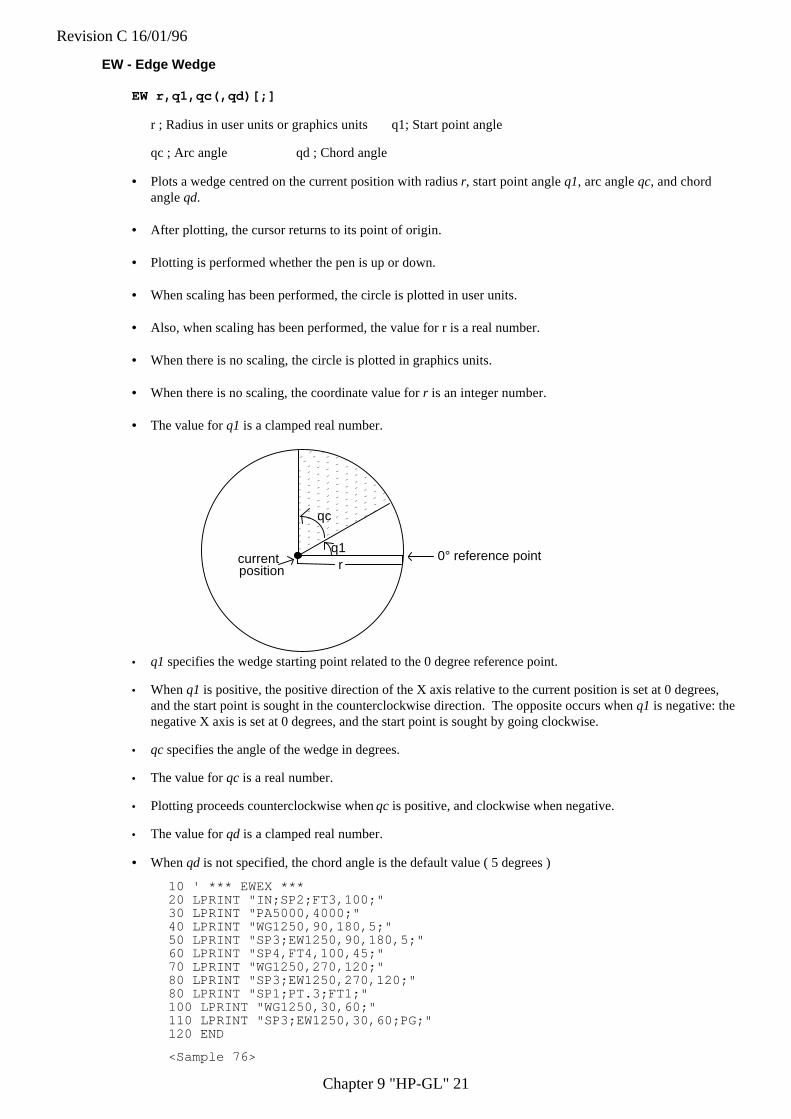
Revision C 16/01/96
Chapter 9 "HP-GL" 21
EW - Edge Wedge
EW r,q1,qc(,qd)[;]
r ; Radius in user units or graphics units q1; Start point angle
qc ; Arc angle qd ; Chord angle
• Plots a wedge centred on the current position with radius r, start point angle q1, arc angle qc, and chordangle qd.
• After plotting, the cursor returns to its point of origin.
• Plotting is performed whether the pen is up or down.
• When scaling has been performed, the circle is plotted in user units.
• Also, when scaling has been performed, the value for r is a real number.
• When there is no scaling, the circle is plotted in graphics units.
• When there is no scaling, the coordinate value for r is an integer number.
• The value for q1 is a clamped real number.
q1
qc
r0° reference pointcurrent
position
• q1 specifies the wedge starting point related to the 0 degree reference point.
• When q1 is positive, the positive direction of the X axis relative to the current position is set at 0 degrees,and the start point is sought in the counterclockwise direction. The opposite occurs when q1 is negative: thenegative X axis is set at 0 degrees, and the start point is sought by going clockwise.
• qc specifies the angle of the wedge in degrees.
• The value for qc is a real number.
• Plotting proceeds counterclockwise when qc is positive, and clockwise when negative.
• The value for qd is a clamped real number.
• When qd is not specified, the chord angle is the default value ( 5 degrees )
10 ' *** EWEX ***20 LPRINT "IN;SP2;FT3,100;"30 LPRINT "PA5000,4000;"40 LPRINT "WG1250,90,180,5;"50 LPRINT "SP3;EW1250,90,180,5;"60 LPRINT "SP4,FT4,100,45;"70 LPRINT "WG1250,270,120;"80 LPRINT "SP3;EW1250,270,120;"80 LPRINT "SP1;PT.3;FT1;"100 LPRINT "WG1250,30,60;"110 LPRINT "SP3;EW1250,30,60;PG;"120 END
<Sample 76>
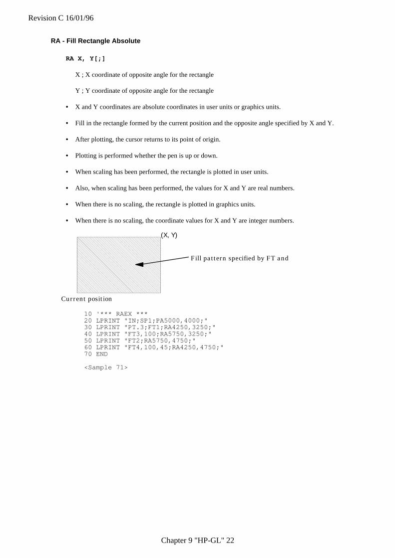
Revision C 16/01/96
Chapter 9 "HP-GL" 22
RA - Fill Rectangle Absolute
RA X, Y[;]
X ; X coordinate of opposite angle for the rectangle
Y ; Y coordinate of opposite angle for the rectangle
• X and Y coordinates are absolute coordinates in user units or graphics units.
• Fill in the rectangle formed by the current position and the opposite angle specified by X and Y.
• After plotting, the cursor returns to its point of origin.
• Plotting is performed whether the pen is up or down.
• When scaling has been performed, the rectangle is plotted in user units.
• Also, when scaling has been performed, the values for X and Y are real numbers.
• When there is no scaling, the rectangle is plotted in graphics units.
• When there is no scaling, the coordinate values for X and Y are integer numbers.
Current position
(X, Y)
Fill pattern specified by FT and P
10 '*** RAEX ***20 LPRINT "IN;SP1;PA5000,4000;"30 LPRINT "PT.3;FT1;RA4250,3250;"40 LPRINT "FT3,100;RA5750,3250;"50 LPRINT "FT2;RA5750,4750;"60 LPRINT "FT4,100,45;RA4250,4750;"70 END
<Sample 71>
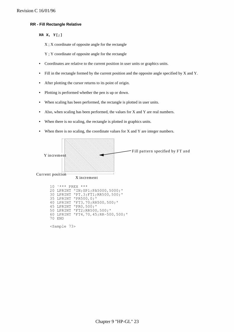
Revision C 16/01/96
Chapter 9 "HP-GL" 23
RR - Fill Rectangle Relative
RR X, Y[;]
X ; X coordinate of opposite angle for the rectangle
Y ; Y coordinate of opposite angle for the rectangle
• Coordinates are relative to the current position in user units or graphics units.
• Fill in the rectangle formed by the current position and the opposite angle specified by X and Y.
• After plotting the cursor returns to its point of origin.
• Plotting is performed whether the pen is up or down.
• When scaling has been performed, the rectangle is plotted in user units.
• Also, when scaling has been performed, the values for X and Y are real numbers.
• When there is no scaling, the rectangle is plotted in graphics units.
• When there is no scaling, the coordinate values for X and Y are integer numbers.
Current position
Fill pattern specified by FT and PY increment
X increment
10 '*** PREX ***20 LPRINT "IN;SP1;PA5000,5000;"30 LPRINT "PT.3;FT1;RR500,500;"35 LPRINT "PR500,0;"40 LPRINT "FT3,70;RR500,500;"45 LPRINT "PR0,500;"50 LPRINT "FT2;RR500,500;"60 LPRINT "FT4,70,45;RR-500,500;"70 END
<Sample 73>
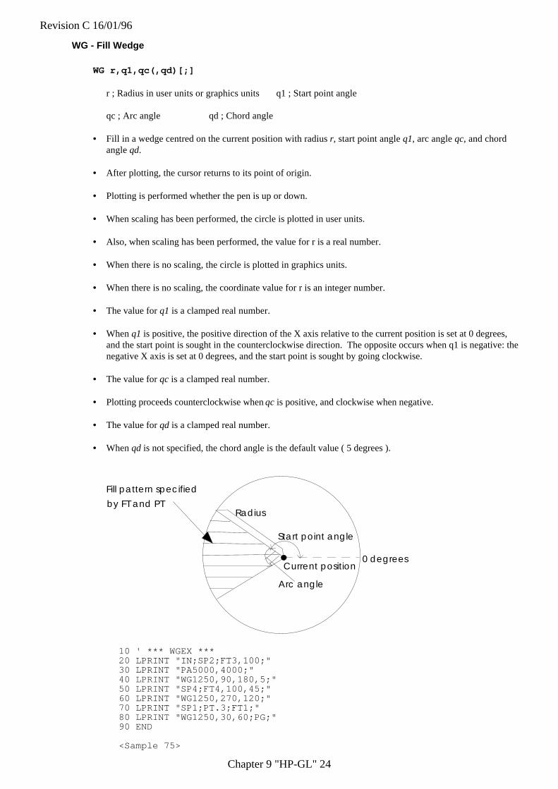
Revision C 16/01/96
Chapter 9 "HP-GL" 24
WG - Fill Wedge
WG r,q1,qc(,qd)[;]
r ; Radius in user units or graphics units q1 ; Start point angle
qc ; Arc angle qd ; Chord angle
• Fill in a wedge centred on the current position with radius r, start point angle q1, arc angle qc, and chordangle qd.
• After plotting, the cursor returns to its point of origin.
• Plotting is performed whether the pen is up or down.
• When scaling has been performed, the circle is plotted in user units.
• Also, when scaling has been performed, the value for r is a real number.
• When there is no scaling, the circle is plotted in graphics units.
• When there is no scaling, the coordinate value for r is an integer number.
• The value for q1 is a clamped real number.
• When q1 is positive, the positive direction of the X axis relative to the current position is set at 0 degrees,and the start point is sought in the counterclockwise direction. The opposite occurs when q1 is negative: thenegative X axis is set at 0 degrees, and the start point is sought by going clockwise.
• The value for qc is a clamped real number.
• Plotting proceeds counterclockwise when qc is positive, and clockwise when negative.
• The value for qd is a clamped real number.
• When qd is not specified, the chord angle is the default value ( 5 degrees ).
Fill pattern specified
by FT and PTRadius
Start point angle
Current position0 degrees
Arc angle
10 ' *** WGEX ***20 LPRINT "IN;SP2;FT3,100;"30 LPRINT "PA5000,4000;"40 LPRINT "WG1250,90,180,5;"50 LPRINT "SP4;FT4,100,45;"60 LPRINT "WG1250,270,120;"70 LPRINT "SP1;PT.3;FT1;"80 LPRINT "WG1250,30,60;PG;"90 END
<Sample 75>
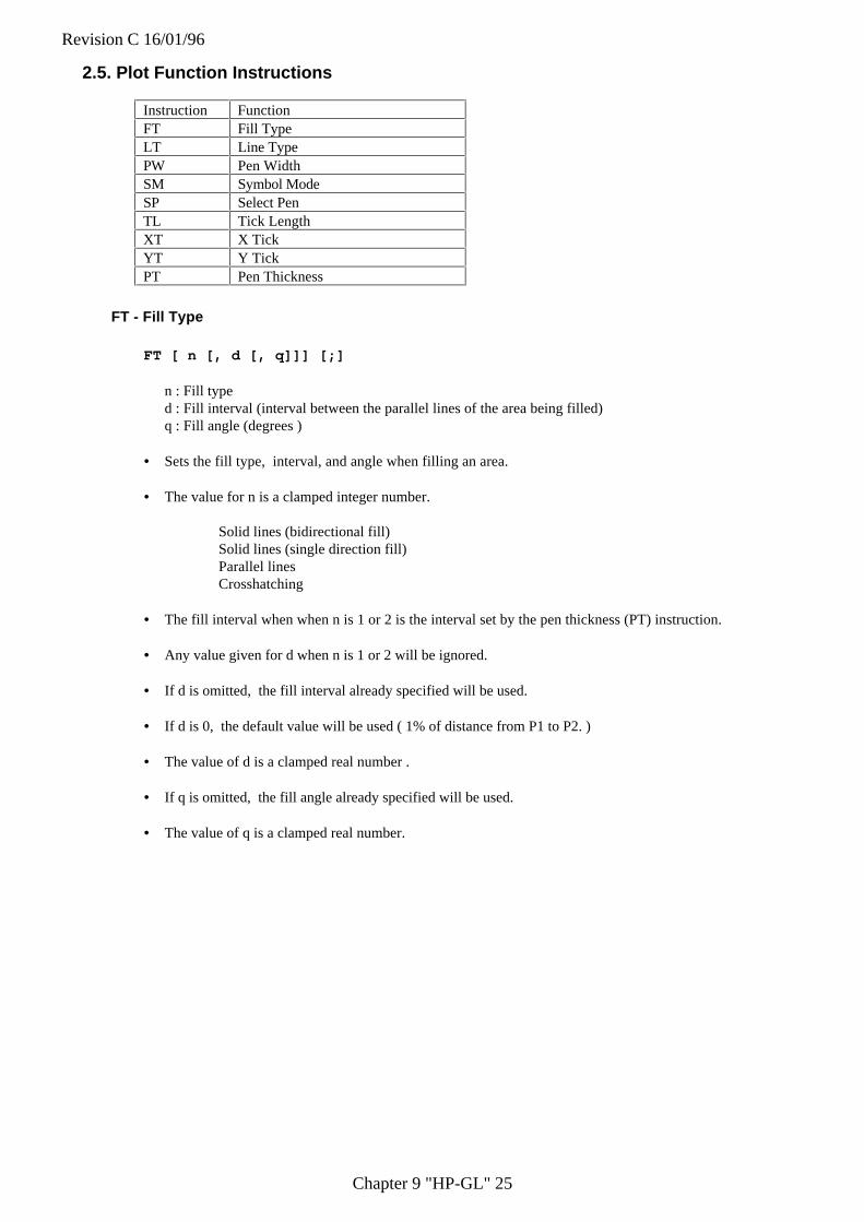
Revision C 16/01/96
Chapter 9 "HP-GL" 25
2.5. Plot Function Instructions
Instruction FunctionFT Fill TypeLT Line TypePW Pen WidthSM Symbol ModeSP Select PenTL Tick LengthXT X TickYT Y TickPT Pen Thickness
FT - Fill Type
FT [ n [, d [, q]]] [;]
n : Fill typed : Fill interval (interval between the parallel lines of the area being filled)q : Fill angle (degrees )
• Sets the fill type, interval, and angle when filling an area.
• The value for n is a clamped integer number.
Solid lines (bidirectional fill)Solid lines (single direction fill)Parallel linesCrosshatching
• The fill interval when when n is 1 or 2 is the interval set by the pen thickness (PT) instruction.
• Any value given for d when n is 1 or 2 will be ignored.
• If d is omitted, the fill interval already specified will be used.
• If d is 0, the default value will be used ( 1% of distance from P1 to P2. )
• The value of d is a clamped real number .
• If q is omitted, the fill angle already specified will be used.
• The value of q is a clamped real number.
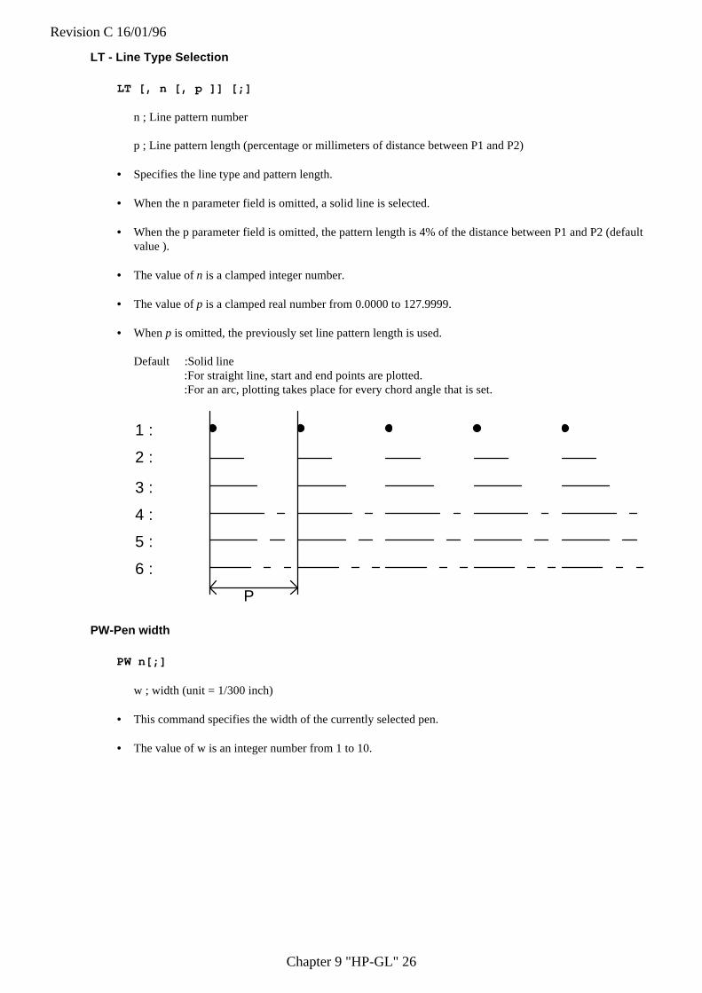
Revision C 16/01/96
Chapter 9 "HP-GL" 26
LT - Line Type Selection
LT [, n [, p ]] [;]
n ; Line pattern number
p ; Line pattern length (percentage or millimeters of distance between P1 and P2)
• Specifies the line type and pattern length.
• When the n parameter field is omitted, a solid line is selected.
• When the p parameter field is omitted, the pattern length is 4% of the distance between P1 and P2 (defaultvalue ).
• The value of n is a clamped integer number.
• The value of p is a clamped real number from 0.0000 to 127.9999.
• When p is omitted, the previously set line pattern length is used.
Default :Solid line:For straight line, start and end points are plotted.:For an arc, plotting takes place for every chord angle that is set.
1 :
2 :
3 :
4 :
5 :
6 :
P
PW-Pen width
PW n[;]
w ; width (unit = 1/300 inch)
• This command specifies the width of the currently selected pen.
• The value of w is an integer number from 1 to 10.
Revision C 16/01/96
Chapter 9 "HP-GL" 27
SM - Symbol Mode
SM c[;]
c ; ASCII character or symbol code
• The command specifies the symbol to be drawn.
• When the PA,PR,PD or PU instruction is used, the specified symbol will be drawn at the end of eachvector.
• The specified symbol will be drawn at the end of each vector even if the pen is up when the PA or PRinstructions are used.
• Omitting the parameter field cancels the symbol mode.
10 '*** SMEX ***20 LPRINT "IN;SP1;SM*;PA500,1500;"30 LPRINT "PD600,1590,670,1860,850,1960,1320,1900,1940,2350:"40 LPRINT "PU;SM;PA500,500;SM3;"50 LPRINT "PA550,800,680,720,800,950,1150,1230,1870,1350;PU;"60 LPRINT "SM;PA1850,600;PD;SMY;PA3000,1450;"70 LPRINT "SMZ;PA3300,1150;SMX;PA1850,600;PU;"80 END
<Sample 78>
SP - Select Pen
SP [ n ] [;]
n ; Pen number
• Selects the pen specified by the pen number.
• The value for n must be an integer from 0 to 6.
TL-Tick Length
TL l1(,l2)[;]
1-Length of ticks in the positive X- and Y-axes2-Length of ticks in the negative X- and Y-axes
• • Tick length is a percentage of the vertical and horizontal distances between P1 and P2.
• Sets the length of tick marks for the XT and YT instructions.
• Values for 1 and 2 are clamped real numbers.
• When the parameter field is omitted, the default values for tick length are used(for both l1 and l2, these are0.5% of the horizontal and vertical distances between P1 and P2).
Revision C 16/01/96
Chapter 9 "HP-GL" 28
10 '*** TLEX ***30 FOR I=1 TO 1040 LPRINT "PR800,0;XT;"50 NEXT I60 LPRINT "TL;PU;PA300,279;PD;"70 GOSUB 100080 LPRINT "TL1,0;PU;PA1100,279;PD;"20 LPRINT "IN;PA300,279;SP2;PD;TL90;XT;";90 GOSUB 1000100 LPRINT "TL0,5;PU;PA1900,279;"110 GOSUB 1000120 LPRINT "PA300,6759;TL80;YT;PU;"130 END1000 '* SUBROUTINE DRAW TICKS *1010 FOR J=1 TO 81020 LPRINT "PRO,720;YT;"1030 NEXT J1040 RETURN
<Sample 77>
XT - X-axis Tick
XT [;]
• Plots vertical tick marks as specified by the TL instruction from the current position.
• After plotting, the cursor returns to its point of origin.
• Plotting is performed whether the pen is up or down.
YT - Y-axis Tick
YT [;]
• Plots horizontal tick marks as specified by the TL instruction from the current position.
• After plotting, the cursor returns to its point of origin.
• Plotting is performed whether the pen is up or down.
10 '*** XTYTEX ***20 LPRINT "IN;PA300,279;SP2;PD";30 LPRINT "PR1300,0;XT;PR1300,0;XT;PU;"40 END
PT - Pen Thickness Select
PT [d] [;]
d : Fill line interval (mm)
• Sets the line interval when filling in with solid lines.
• The value for d is a clamped number from 0.0000 to 5.0000.
• The default value (0.3 mm) is in effect when d is omitted.
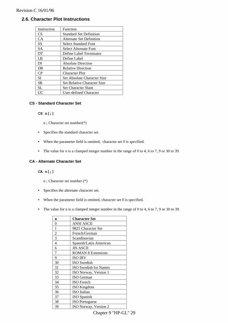
Revision C 16/01/96
Chapter 9 "HP-GL" 29
2.6. Character Plot Instructions
Instruction FunctionCS Standard Set DefinitionCA Alternate Set DefinitionSS Select Standard FontSA Select Alternate FontDT Define Label TerminatorLB Define LabelDI Absolute DirectionDR Relative DirectionCP Character PlotSI Set Absolute Character SizeSR Set Relative Character SizeSL Set Character SlantUC User-defined Character
CS - Standard Character Set
CS n[;]
n ; Character set number(*)
• Specifies the standard character set.
• When the parameter field is omitted, character set 0 is specified.
• The value for n is a clamped integer number in the range of 0 to 4, 6 to 7, 9 or 30 to 39.
CA - Alternate Character Set
CA n[;]
n ; Character set number (*)
• Specifies the alternate character set.
• When the parameter field is omitted, character set 0 is specified.
• The value for n is a clamped integer number in the range of 0 to 4, 6 to 7, 9 or 30 to 39.
n Character Set0 ANSI ASCII1 9825 Character Set2 French/German3 Scandinavian4 Spanish/Latin American6 JIS ASCII7 ROMAN 8 Extensions9 ISO IRV30 ISO Swedish31 ISO Swedish for Names32 ISO Norway, Version 133 ISO German34 ISO French35 ISO Kingdom36 ISO Italian37 ISO Spanish38 ISO Portuguese39 ISO Norway, Version 2
Revision C 16/01/96
Chapter 9 "HP-GL" 30
SS - Select Standard Character Set
SS [;]
• Selects the standard character set specified by the CS instruction.
SA - Select Alternate Character Set
SA [;]
• Selects the alternate character set specified by the CA instruction.
10 '*** SASSEX ***20 LPRINT "PA5000,5000;"30 LPRINT "SP2;CS4;CA9;SS;LBS_E_T_4";CHR$(14);"S_E_T_9";CHR$(3)
40 ENDø
<Sample 79>
DT - Define Label Terminator
DT c [;]
c : Character
• The specified character is used as the character plotter terminator.
• The character plot mode is cancelled by sending a terminator at the end of a character plot string.
• The parameter field used for this command must be only one character in length.
• The default value (chr$(3)) is used when the parameter field is omitted.
10 '*** DTEX ***20 LPRINT "IN;SP2;SC0,5000,0,5000;"30 LPRINT "PA0,4500;LBDefault control characterETX";CHR$(13);CHR$(3);40 LPRINT "LBterminates by performing end-";CHR$(13);CHR$(3):50 LPRINT "LBof-text function.";CHR$(3);60 LPRINT "PA0,3500;DT@;LBPrinting charactersterminate,";CHR$(13):"@";70 LPRINT "LBbut are also printed.@";80 LPRINT "PA0,3000;DT";CHR$(13);";LBcontrol charactersterminate";CHR$(10);CHR$(13)90 LPRINT "LBand perform their function.";CHR$(13)100 END
<Sample 80>
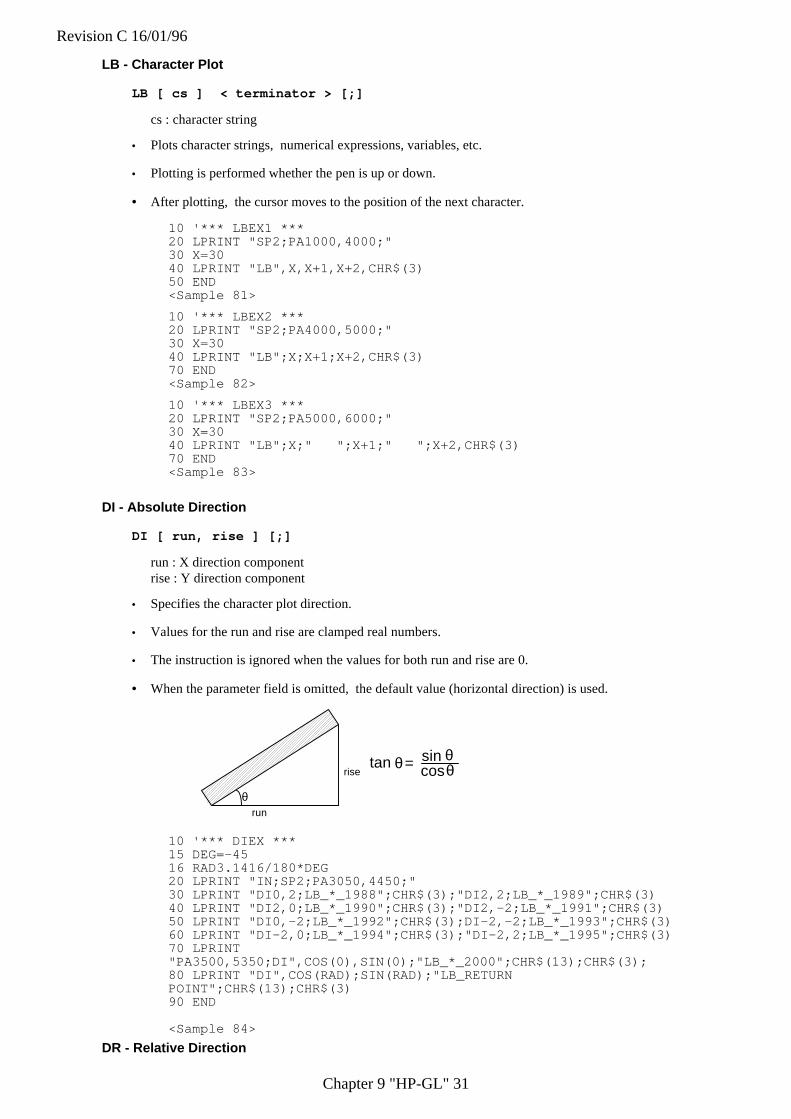
Revision C 16/01/96
Chapter 9 "HP-GL" 31
LB - Character Plot
LB [ cs ] < terminator > [;]
cs : character string
• Plots character strings, numerical expressions, variables, etc.
• Plotting is performed whether the pen is up or down.
• After plotting, the cursor moves to the position of the next character.
10 '*** LBEX1 ***20 LPRINT "SP2;PA1000,4000;"30 X=3040 LPRINT "LB",X,X+1,X+2,CHR$(3)50 END<Sample 81>
10 '*** LBEX2 ***20 LPRINT "SP2;PA4000,5000;"30 X=3040 LPRINT "LB";X;X+1;X+2,CHR$(3)70 END<Sample 82>
10 '*** LBEX3 ***20 LPRINT "SP2;PA5000,6000;"30 X=3040 LPRINT "LB";X;" ";X+1;" ";X+2,CHR$(3)70 END<Sample 83>
DI - Absolute Direction
DI [ run, rise ] [;]
run : X direction componentrise : Y direction component
• Specifies the character plot direction.
• Values for the run and rise are clamped real numbers.
• The instruction is ignored when the values for both run and rise are 0.
• When the parameter field is omitted, the default value (horizontal direction) is used.
θrun
risetan θ = cos
sinθθ
10 '*** DIEX ***15 DEG=-4516 RAD3.1416/180*DEG20 LPRINT "IN;SP2;PA3050,4450;"30 LPRINT "DI0,2;LB_*_1988";CHR$(3);"DI2,2;LB_*_1989";CHR$(3)40 LPRINT "DI2,0;LB_*_1990";CHR$(3);"DI2,-2;LB_*_1991";CHR$(3)50 LPRINT "DI0,-2;LB_*_1992";CHR$(3);DI-2,-2;LB_*_1993";CHR$(3)60 LPRINT "DI-2,0;LB_*_1994";CHR$(3);"DI-2,2;LB_*_1995";CHR$(3)70 LPRINT"PA3500,5350;DI",COS(0),SIN(0);"LB_*_2000";CHR$(13);CHR$(3);80 LPRINT "DI",COS(RAD);SIN(RAD);"LB_RETURNPOINT";CHR$(13);CHR$(3)90 END
<Sample 84>
DR - Relative Direction
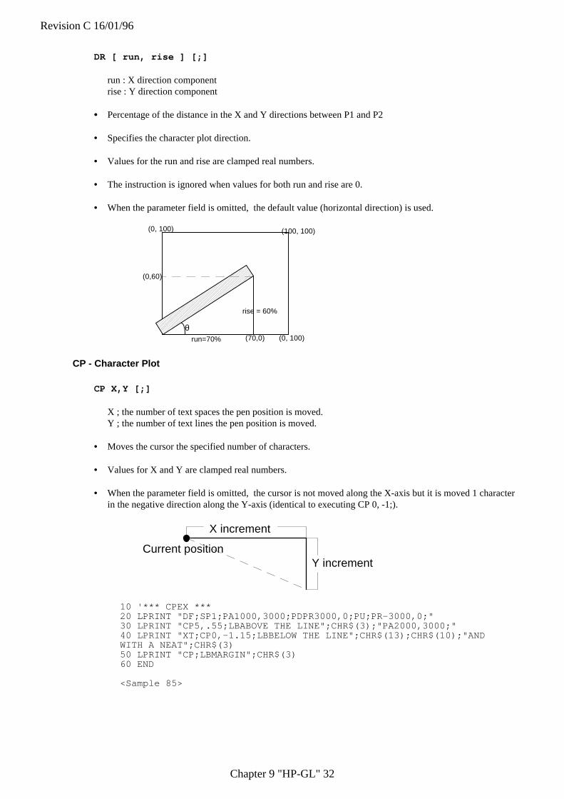
Revision C 16/01/96
Chapter 9 "HP-GL" 32
DR [ run, rise ] [;]
run : X direction componentrise : Y direction component
• • Percentage of the distance in the X and Y directions between P1 and P2
• Specifies the character plot direction.
• Values for the run and rise are clamped real numbers.
• The instruction is ignored when values for both run and rise are 0.
• When the parameter field is omitted, the default value (horizontal direction) is used.
θrun=70%
rise = 60%
(70,0)
(0,60)
(0, 100)
(0, 100)
(100, 100)
CP - Character Plot
CP X,Y [;]
X ; the number of text spaces the pen position is moved.Y ; the number of text lines the pen position is moved.
• Moves the cursor the specified number of characters.
• Values for X and Y are clamped real numbers.
• When the parameter field is omitted, the cursor is not moved along the X-axis but it is moved 1 characterin the negative direction along the Y-axis (identical to executing CP 0, -1;).
X increment
Y incrementCurrent position
10 '*** CPEX ***20 LPRINT "DF;SP1;PA1000,3000;PDPR3000,0;PU;PR-3000,0;"30 LPRINT "CP5,.55;LBABOVE THE LINE";CHR$(3);"PA2000,3000;"40 LPRINT "XT;CP0,-1.15;LBBELOW THE LINE";CHR$(13);CHR$(10);"ANDWITH A NEAT";CHR$(3)50 LPRINT "CP;LBMARGIN";CHR$(3)60 END
<Sample 85>
Revision C 16/01/96
Chapter 9 "HP-GL" 33
SI - Set Absolute Character Size
SI [ width, height ] [;]
width : the width in centimeters of printed charactersheight : the height in centimeters of printed characters
• Specifies the size of characters to be plotted.
• Values for width and height are clamped real numbers.
• When the parameter field is omitted, the default values are used (width: 0.1879 cm, height: 0.2690 cm).
10 '*** SIEX1 ***20 LPRINT "IN;SP1;PA1000,1000;"30 LPRINT "SI2,1.5;LBLASER";CHR$(3)40 END
<Sample 86>
10 '*** SIEX2 ***20 LPRINT "IN;SP1;PA5000,3000:"30 LPRINT "SI-.35,.35;LBCHARACTER";CHR$(3)40 END
<Sample 87>
10 '*** SIEX3 ***20 LPRINT "IN;SP1;PA5000,3000;"30 LPRINT "SI.35,-.35;LBCHARACTER";CHR$(3)40 END
<Sample 88>
10 '*** SIEX4 ***20 LPRINT "IN;SP1;PA5000,3000;"30 LPRINT "SI-.35,-.35;LBCHARACTER";CHR$(3)40 END
<Sample 89>

Revision C 16/01/96
Chapter 9 "HP-GL" 34
SR - Set Relative Character Size
SR [ width , height ] [;]
width ; the width of printed characters expressed as a percentage of the x-component of the distancebetween P1 and P2.
height ; the height of printed characters expressed as a percentage of the y-component of the distancebetween P1 and P2.
• Specifies the size of characters to be plotted.
• Values for width and height are clamped real numbers.
• When the parameter field is omitted, the default values are used (width: 0.7500%, height: 1.5000%).
10 ' *** SREX ***20 LPRINT "IN;SP2;PA100,7000;LBDEFAULT SIZE";CHR$(3)30 LPRINT "IP 2000,2000,6500,6500;PA100,6500;"40 LPRINT "LBNEW P1 AND P2 CHANGE LABEL SIZE";CHR$(3);"SR5,5;"50 LPRINT "PA100,6000;LBNEW SR INSTRUCTION";CHR$(13);CHR$(3);60 LPRINT "LBCHANGE LABEL SIZE";CHR$(3);
<Sample 90>
SL - Character Slant
SL [ tan φφ ] [;]
tan φ - tangent of character slant angle (φ)
• Specifies the slant of characters to be plotted.
• Value for tanθ is a clamped real number.
• When the parameter field is omitted, the default value is used (0 degree character slant).
θ
10 '"*** SLEX ***20 LPRINT "DF;SP1;SI1.3,1.3;PA100,6000;"30 LPRINT "SL2;LBLASER";CHR$(3)40 LPRINT "SL-2;PR3000,0;LBLASER";CHR$(3)50 END
<Sample 91>
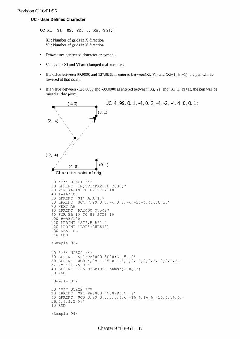
Revision C 16/01/96
Chapter 9 "HP-GL" 35
UC - User Defined Character
UC X1, Y1, X2, Y2..., Xn, Yn[;]
Xi : Number of grids in X directionYi : Number of grids in Y direction
• Draws user-generated character or symbol.
• Values for Xi and Yi are clamped real numbers.
• If a value between 99.0000 and 127.9999 is entered between(Xi, Yi) and (Xi+1, Yi+1), the pen will belowered at that point.
• If a value between -128.0000 and -99.0000 is entered between (Xi, Yi) and (Xi+1, Yi+1), the pen will beraised at that point.
(-4,0)
(2, -4)
(-2, -4)
(4, 0) (0, 1)
(0, 1)
UC 4, 99, 0, 1, -4, 0, 2, -4, -2, -4, 4, 0, 0, 1;
Character point of origin
10 '*** UCEX1 ***20 LPRINT "IN;SP2;PA2000,2000;"30 FOR AA=19 TO 89 STEP 1040 A=AA/10050 LPRINT "SI",A,A*1.760 LPRINT "UC4,7,99,0,1,-4,0,2,-4,-2,-4,4,0,0,1;"70 NEXT AA80 LPRINT "PA2000,3750;"90 FOR BB=19 TO 89 STEP 10100 B=BB/100110 LPRINT "SI",B,B*1.7120 LPRINT "LBE";CHR$(3)130 NEXT BB140 END
<Sample 92>
10 '*** UCEX2 ***20 LPRINT "SP1;PA3000,5000;SI.5,.8"30 LPRINT "UC0,4,99,1.75,0,1.5,4,3,-8,3,8,3,-8,3,8,3,-8,1.5,4,1.75,0;"40 LPRINT "CP5,0;LB1000 ohms";CHR$(3)50 END
<Sample 93>
10 '*** UCEX2 ***20 LPRINT "SP1;PA3000,4500;SI.5,.8"30 LPRINT "UC0,8,99,3.5,0,3,8,6,-16,6,16,6,-16,6,16,6,-16,3,8,3.5,0;"40 END
<Sample 94>
Revision C 16/01/96
Chapter 9 "HP-GL" 36
2.7. dual context extensions
Set High Resolution Control (Brother Original)
EscCRRO
• This command sets high resolution control off.
EscCRRL
• This command sets high resolution control light level.
EscCRRM
• This command sets high resolution control medium level.
EscCRRD
• This command sets high resolution control dark level.
USER RESET (Brother Original)
EscCR!#R
• # can be 0, 1 or 2.
• #0 indicates the current setting are restored.
• #1 indicates the user settings 1 are restored.
• #2 indicates the user settings 2 are restored.
FACTORY RESET (Brother Original)
EscCRFD
• This command causes a factory reset to be performed, restoring all the printer's factory default settings.
• You can also perform a factory reset using the printer's control panel (see the User Guide).
Revision C 16/01/96
APPENDIX A -COMPALISON LIST-1
APPENDIX A
COMPARISON LIST FORHL-660, HL-1260, HL-10h, HL-10V/DV, HL-10PS/DPS,
HL-8V, HL-4V, HL-4Ve, and HL-6V
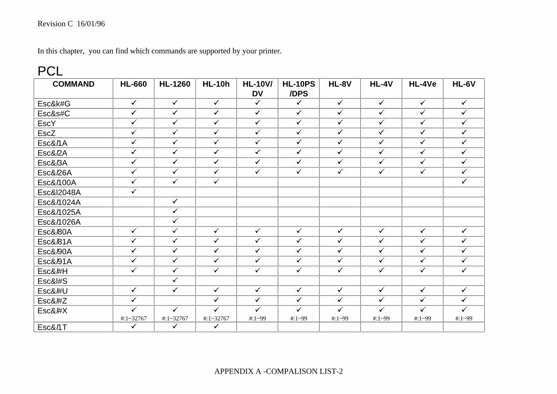
Revision C 16/01/96
APPENDIX A -COMPALISON LIST-2
In this chapter, you can find which commands are supported by your printer.
PCLCOMMAND HL-660 HL-1260 HL-10h HL-10V/
DVHL-10PS
/DPSHL-8V HL-4V HL-4Ve HL-6V
Esc&k#G ü ü ü ü ü ü ü ü ü
Esc&s#C ü ü ü ü ü ü ü ü ü
EscY ü ü ü ü ü ü ü ü ü
EscZ ü ü ü ü ü ü ü ü ü
Esc&l1A ü ü ü ü ü ü ü ü ü
Esc&l2A ü ü ü ü ü ü ü ü ü
Esc&l3A ü ü ü ü ü ü ü ü ü
Esc&l26A ü ü ü ü ü ü ü ü ü
Esc&l100A ü ü ü ü
Esc&l2048A ü
Esc&l1024A ü
Esc&l1025A ü
Esc&l1026A ü
Esc&l80A ü ü ü ü ü ü ü ü ü
Esc&l81A ü ü ü ü ü ü ü ü ü
Esc&l90A ü ü ü ü ü ü ü ü ü
Esc&l91A ü ü ü ü ü ü ü ü ü
Esc&l#H ü ü ü ü ü ü ü ü ü
Esc&l#S ü
Esc&l#U ü ü ü ü ü ü ü ü ü
Esc&l#Z ü ü ü ü ü ü ü ü
Esc&l#X ü
#:1~32767ü
#:1~32767ü
#:1~32767ü
#:1~99ü
#:1~99ü
#:1~99ü
#:1~99ü
#:1~99ü
#:1~99
Esc&l1T ü ü ü
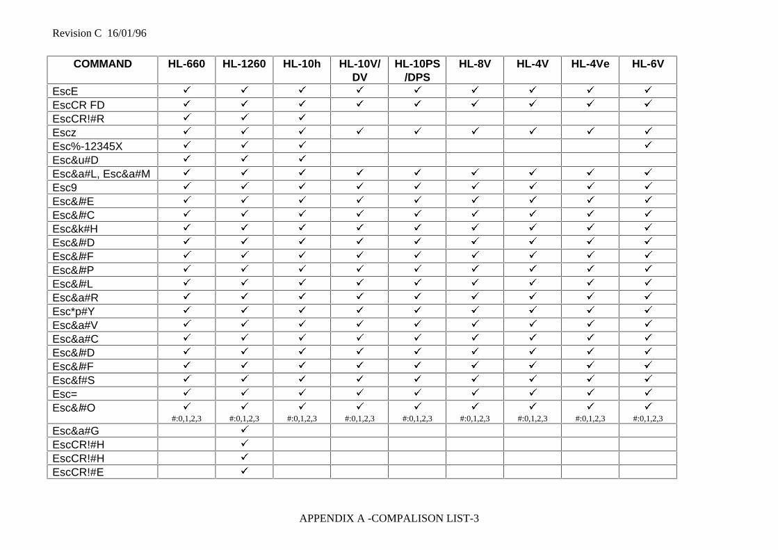
Revision C 16/01/96
APPENDIX A -COMPALISON LIST-3
COMMAND HL-660 HL-1260 HL-10h HL-10V/DV
HL-10PS/DPS
HL-8V HL-4V HL-4Ve HL-6V
EscE ü ü ü ü ü ü ü ü ü
EscCR FD ü ü ü ü ü ü ü ü ü
EscCR!#R ü ü ü
Escz ü ü ü ü ü ü ü ü ü
Esc%-12345X ü ü ü ü
Esc&u#D ü ü ü
Esc&a#L, Esc&a#M ü ü ü ü ü ü ü ü ü
Esc9 ü ü ü ü ü ü ü ü ü
Esc&l#E ü ü ü ü ü ü ü ü ü
Esc&l#C ü ü ü ü ü ü ü ü ü
Esc&k#H ü ü ü ü ü ü ü ü ü
Esc&l#D ü ü ü ü ü ü ü ü ü
Esc&l#F ü ü ü ü ü ü ü ü ü
Esc&l#P ü ü ü ü ü ü ü ü ü
Esc&l#L ü ü ü ü ü ü ü ü ü
Esc&a#R ü ü ü ü ü ü ü ü ü
Esc*p#Y ü ü ü ü ü ü ü ü ü
Esc&a#V ü ü ü ü ü ü ü ü ü
Esc&a#C ü ü ü ü ü ü ü ü ü
Esc&l#D ü ü ü ü ü ü ü ü ü
Esc&l#F ü ü ü ü ü ü ü ü ü
Esc&f#S ü ü ü ü ü ü ü ü ü
Esc= ü ü ü ü ü ü ü ü ü
Esc&l#O ü
#:0,1,2,3ü
#:0,1,2,3ü
#:0,1,2,3ü
#:0,1,2,3ü
#:0,1,2,3ü
#:0,1,2,3ü
#:0,1,2,3ü
#:0,1,2,3ü
#:0,1,2,3
Esc&a#G ü
EscCR!#H ü
EscCR!#H ü
EscCR!#E ü
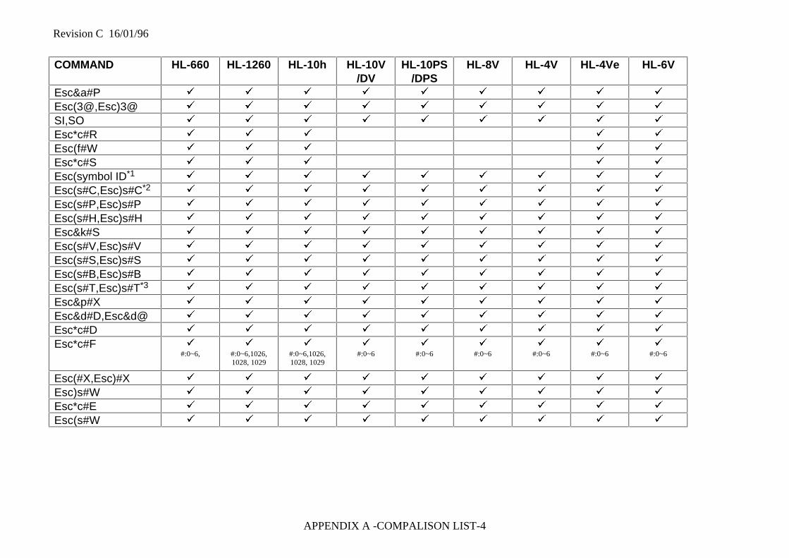
Revision C 16/01/96
APPENDIX A -COMPALISON LIST-4
COMMAND HL-660 HL-1260 HL-10h HL-10V/DV
HL-10PS/DPS
HL-8V HL-4V HL-4Ve HL-6V
Esc&a#P ü ü ü ü ü ü ü ü ü
Esc(3@,Esc)3@ ü ü ü ü ü ü ü ü ü
SI,SO ü ü ü ü ü ü ü ü ü
Esc*c#R ü ü ü ü ü
Esc(f#W ü ü ü ü ü
Esc*c#S ü ü ü ü ü
Esc(symbol ID*1 ü ü ü ü ü ü ü ü ü
Esc(s#C,Esc)s#C*2 ü ü ü ü ü ü ü ü ü
Esc(s#P,Esc)s#P ü ü ü ü ü ü ü ü ü
Esc(s#H,Esc)s#H ü ü ü ü ü ü ü ü ü
Esc&k#S ü ü ü ü ü ü ü ü ü
Esc(s#V,Esc)s#V ü ü ü ü ü ü ü ü ü
Esc(s#S,Esc)s#S ü ü ü ü ü ü ü ü ü
Esc(s#B,Esc)s#B ü ü ü ü ü ü ü ü ü
Esc(s#T,Esc)s#T*3 ü ü ü ü ü ü ü ü ü
Esc&p#X ü ü ü ü ü ü ü ü ü
Esc&d#D,Esc&d@ ü ü ü ü ü ü ü ü ü
Esc*c#D ü ü ü ü ü ü ü ü ü
Esc*c#F ü
#:0~6,ü
#:0~6,1026,1028, 1029
ü
#:0~6,1026,1028, 1029
ü
#:0~6ü
#:0~6ü
#:0~6ü
#:0~6ü
#:0~6ü
#:0~6
Esc(#X,Esc)#X ü ü ü ü ü ü ü ü ü
Esc)s#W ü ü ü ü ü ü ü ü ü
Esc*c#E ü ü ü ü ü ü ü ü ü
Esc(s#W ü ü ü ü ü ü ü ü ü

Revision C 16/01/96
APPENDIX A -COMPALISON LIST-5
COMMAND HL-660 HL-1260 HL-10h HL-10V/DV
HL-10PS/DPS
HL-8V HL-4V HL-4Ve HL-6V
Esc*v#N ü ü ü ü ü ü ü ü ü
Esc*v#O ü ü ü ü ü ü ü ü ü
Esc*c#G ü ü ü ü ü ü ü ü ü
Esc*c#W ü ü ü ü ü
Esc*p#R ü ü ü ü ü
Esc*c#Q ü ü ü ü ü
Esc*v#T ü
#:0~4,130ü
#:0~4,130ü
#:0~4,130ü
#:0~3,130ü
#:0~3,130ü
#:0~3, 130ü
#:0~3, 130ü
#:0~4, 130ü
#:0~4, 130
Esc*c#A,Esc*c#H ü ü ü ü ü ü ü ü ü
Esc*c#B,Esc*c#V ü ü ü ü ü ü ü ü ü
Esc*c#P ü
#:0~5,130ü
#:0~5,130ü
#:0~5,130ü
#:0,1,2,3,5ü
#:0~3,5,130ü
#:0~5, 130ü
#:0~5,130ü
#:0~5, 130ü
#:0~5, 130
Esc*t#R ü
#:75,100,150,200,300,600
ü
#:75,100,150,200, 300,600
ü
#:75,100,150,200,300,600
ü
#:75,100,150,300
ü
#:75,100,150,300
ü
#:75,100,150,300
ü
#:75,100,150,300
ü
#:75,100,150,300
ü
#:75,100,150,300
Esc*r#F ü ü ü ü ü ü ü ü ü
Esc*r#T ü ü ü ü ü ü ü ü ü
Esc*r#S ü ü ü ü ü ü ü ü ü
Esc*b#Y ü ü ü ü ü ü ü ü ü
Esc*b#M ü
#:0,1,2,3,5,9,1024, 1152
ü
#:0,1,2,3,5,9,1024, 1152
ü
#:0,1,2,3,5,9,1024, 1152
ü
#:0,1,2,3ü
#:0,1,2,3ü
#:0,1,2,3ü
#:0,1,2,3ü
#:0,1,2,3ü
#:0,1,2,3,5,9
Esc*r#A ü ü ü ü ü ü ü ü ü
Esc*b#W ü ü ü ü ü ü ü ü ü
Esc*b#C ü ü ü ü ü ü ü ü ü
Esc*rB ü ü ü ü ü ü ü ü ü
Esc*rC ü ü ü ü ü ü
Esc%#B ü ü ü ü ü ü ü ü ü
Esc*c0T ü ü ü ü ü ü ü ü ü
Esc*c#Y ü ü ü ü ü ü ü ü ü
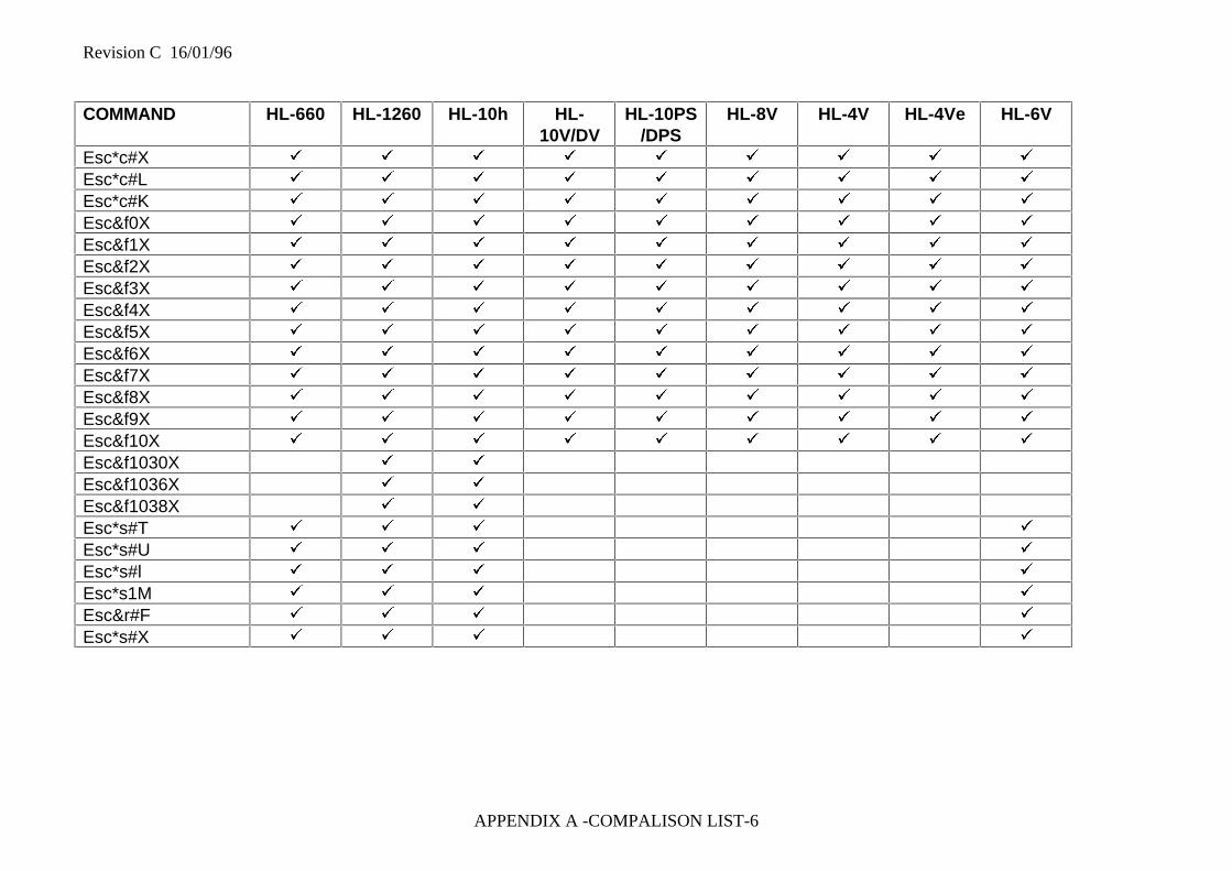
Revision C 16/01/96
APPENDIX A -COMPALISON LIST-6
COMMAND HL-660 HL-1260 HL-10h HL-10V/DV
HL-10PS/DPS
HL-8V HL-4V HL-4Ve HL-6V
Esc*c#X ü ü ü ü ü ü ü ü ü
Esc*c#L ü ü ü ü ü ü ü ü ü
Esc*c#K ü ü ü ü ü ü ü ü ü
Esc&f0X ü ü ü ü ü ü ü ü ü
Esc&f1X ü ü ü ü ü ü ü ü ü
Esc&f2X ü ü ü ü ü ü ü ü ü
Esc&f3X ü ü ü ü ü ü ü ü ü
Esc&f4X ü ü ü ü ü ü ü ü ü
Esc&f5X ü ü ü ü ü ü ü ü ü
Esc&f6X ü ü ü ü ü ü ü ü ü
Esc&f7X ü ü ü ü ü ü ü ü ü
Esc&f8X ü ü ü ü ü ü ü ü ü
Esc&f9X ü ü ü ü ü ü ü ü ü
Esc&f10X ü ü ü ü ü ü ü ü ü
Esc&f1030X ü ü
Esc&f1036X ü ü
Esc&f1038X ü ü
Esc*s#T ü ü ü ü
Esc*s#U ü ü ü ü
Esc*s#l ü ü ü ü
Esc*s1M ü ü ü ü
Esc&r#F ü ü ü ü
Esc*s#X ü ü ü ü
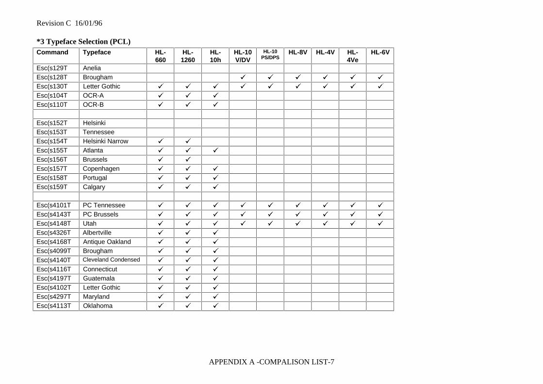
Revision C 16/01/96
APPENDIX A -COMPALISON LIST-7
*3 Typeface Selection (PCL)Command Typeface HL-
660HL-1260
HL-10h
HL-10V/DV
HL-10PS/DPS
HL-8V HL-4V HL-4Ve
HL-6V
Esc(s129T AneliaEsc(s128T Brougham ü ü ü ü ü ü
Esc(s130T Letter Gothic ü ü ü ü ü ü ü ü ü
Esc(s104T OCR-A ü ü ü
Esc(s110T OCR-B ü ü ü
Esc(s152T HelsinkiEsc(s153T TennesseeEsc(s154T Helsinki Narrow ü ü
Esc(s155T Atlanta ü ü ü
Esc(s156T Brussels ü ü
Esc(s157T Copenhagen ü ü ü
Esc(s158T Portugal ü ü ü
Esc(s159T Calgary ü ü ü
Esc(s4101T PC Tennessee ü ü ü ü ü ü ü ü ü
Esc(s4143T PC Brussels ü ü ü ü ü ü ü ü ü
Esc(s4148T Utah ü ü ü ü ü ü ü ü ü
Esc(s4326T Albertville ü ü ü
Esc(s4168T Antique Oakland ü ü ü
Esc(s4099T Brougham ü ü ü
Esc(s4140T Cleveland Condensed ü ü ü
Esc(s4116T Connecticut ü ü ü
Esc(s4197T Guatemala ü ü ü
Esc(s4102T Letter Gothic ü ü ü
Esc(s4297T Maryland ü ü ü
Esc(s4113T Oklahoma ü ü ü

Revision C 16/01/96
APPENDIX A -COMPALISON LIST-8
Command Typeface HL-660
HL-1260
HL-10h
HL-10V/DV
HL-10PS/DPS
HL-8V HL-4V HL-4Ve
HL-6V
Esc(s16696T BR Symbol ü ü ü
Esc(s16602T Helsinki ü ü ü
Esc(s16901T Tennessee ü ü ü
Esc(s31402T W Dingbats ü ü ü
ESC(s134T Bermuda Script ü
ESC(s132T Germany ü
ESC(s133T San Diego ü
ESC(s135T US Roman ü
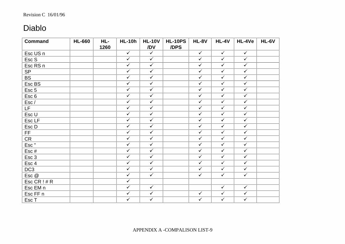
Revision C 16/01/96
APPENDIX A -COMPALISON LIST-9
Diablo
Command HL-660 HL-1260
HL-10h HL-10V/DV
HL-10PS/DPS
HL-8V HL-4V HL-4Ve HL-6V
Esc US n ü ü ü ü ü
Esc S ü ü ü ü ü
Esc RS n ü ü ü ü ü
SP ü ü ü ü ü
BS ü ü ü ü ü
Esc BS ü ü ü ü ü
Esc 5 ü ü ü ü ü
Esc 6 ü ü ü ü ü
Esc / ü ü ü ü ü
LF ü ü ü ü ü
Esc U ü ü ü ü ü
Esc LF ü ü ü ü ü
Esc D ü ü ü ü ü
FF ü ü ü ü ü
CR ü ü ü ü ü
Esc " ü ü ü ü ü
Esc # ü ü ü ü ü
Esc 3 ü ü ü ü ü
Esc 4 ü ü ü ü ü
DC3 ü ü ü ü ü
Esc @ ü ü ü ü ü
Esc CR ! # R ü
Esc EM n ü ü ü ü
Esc FF n ü ü ü ü ü
Esc T ü ü ü ü ü
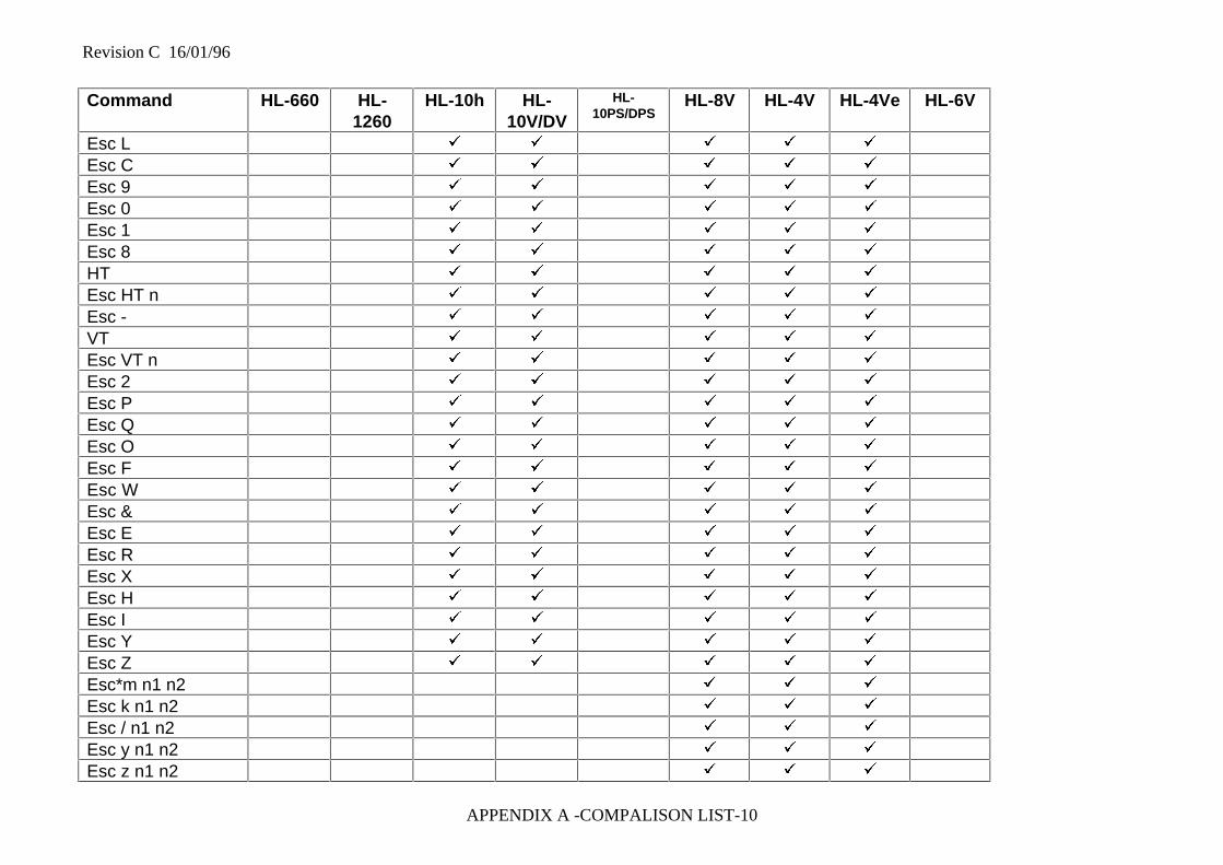
Revision C 16/01/96
APPENDIX A -COMPALISON LIST-10
Command HL-660 HL-1260
HL-10h HL-10V/DV
HL-10PS/DPS
HL-8V HL-4V HL-4Ve HL-6V
Esc L ü ü ü ü ü
Esc C ü ü ü ü ü
Esc 9 ü ü ü ü ü
Esc 0 ü ü ü ü ü
Esc 1 ü ü ü ü ü
Esc 8 ü ü ü ü ü
HT ü ü ü ü ü
Esc HT n ü ü ü ü ü
Esc - ü ü ü ü ü
VT ü ü ü ü ü
Esc VT n ü ü ü ü ü
Esc 2 ü ü ü ü ü
Esc P ü ü ü ü ü
Esc Q ü ü ü ü ü
Esc O ü ü ü ü ü
Esc F ü ü ü ü ü
Esc W ü ü ü ü ü
Esc & ü ü ü ü ü
Esc E ü ü ü ü ü
Esc R ü ü ü ü ü
Esc X ü ü ü ü ü
Esc H ü ü ü ü ü
Esc I ü ü ü ü ü
Esc Y ü ü ü ü ü
Esc Z ü ü ü ü ü
Esc*m n1 n2 ü ü ü
Esc k n1 n2 ü ü ü
Esc / n1 n2 ü ü ü
Esc y n1 n2 ü ü ü
Esc z n1 n2 ü ü ü
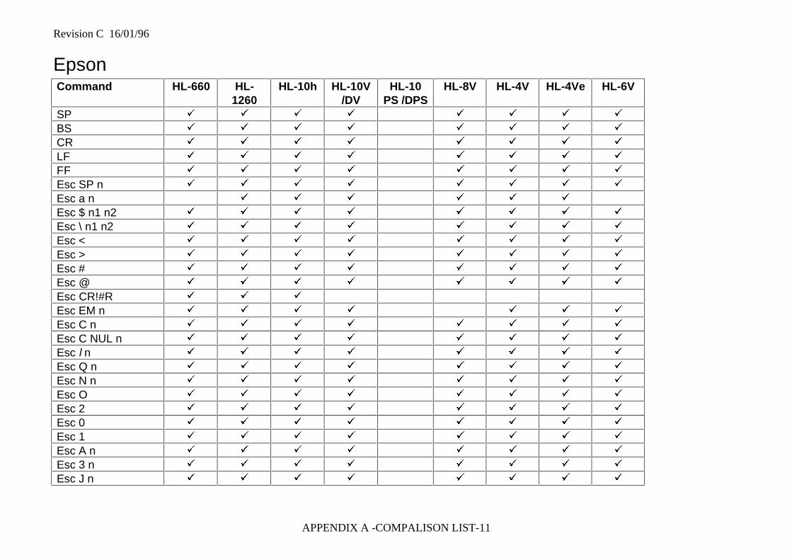
Revision C 16/01/96
APPENDIX A -COMPALISON LIST-11
EpsonCommand HL-660 HL-
1260HL-10h HL-10V
/DVHL-10
PS /DPSHL-8V HL-4V HL-4Ve HL-6V
SP ü ü ü ü ü ü ü ü
BS ü ü ü ü ü ü ü ü
CR ü ü ü ü ü ü ü ü
LF ü ü ü ü ü ü ü ü
FF ü ü ü ü ü ü ü ü
Esc SP n ü ü ü ü ü ü ü ü
Esc a n ü ü ü ü ü ü
Esc $ n1 n2 ü ü ü ü ü ü ü ü
Esc \ n1 n2 ü ü ü ü ü ü ü ü
Esc < ü ü ü ü ü ü ü ü
Esc > ü ü ü ü ü ü ü ü
Esc # ü ü ü ü ü ü ü ü
Esc @ ü ü ü ü ü ü ü ü
Esc CR!#R ü ü ü
Esc EM n ü ü ü ü ü ü ü
Esc C n ü ü ü ü ü ü ü ü
Esc C NUL n ü ü ü ü ü ü ü ü
Esc l n ü ü ü ü ü ü ü ü
Esc Q n ü ü ü ü ü ü ü ü
Esc N n ü ü ü ü ü ü ü ü
Esc O ü ü ü ü ü ü ü ü
Esc 2 ü ü ü ü ü ü ü ü
Esc 0 ü ü ü ü ü ü ü ü
Esc 1 ü ü ü ü ü ü ü ü
Esc A n ü ü ü ü ü ü ü ü
Esc 3 n ü ü ü ü ü ü ü ü
Esc J n ü ü ü ü ü ü ü ü
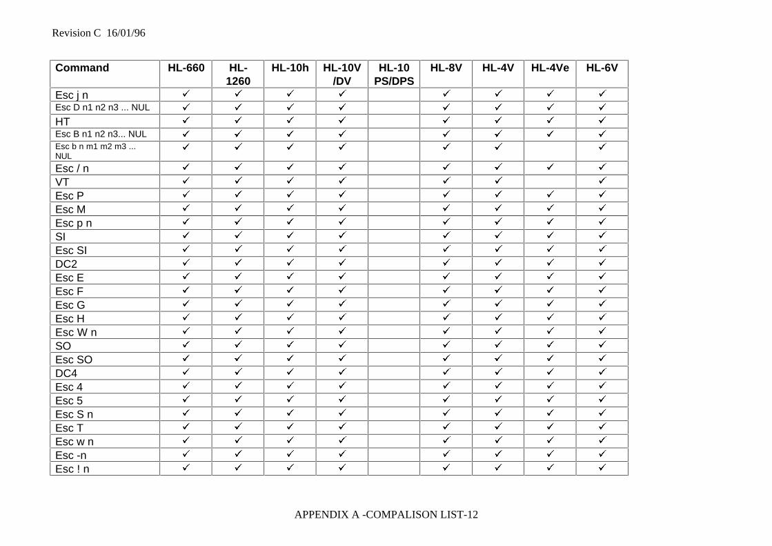
Revision C 16/01/96
APPENDIX A -COMPALISON LIST-12
Command HL-660 HL-1260
HL-10h HL-10V/DV
HL-10PS/DPS
HL-8V HL-4V HL-4Ve HL-6V
Esc j n ü ü ü ü ü ü ü ü
Esc D n1 n2 n3 ... NUL ü ü ü ü ü ü ü ü
HT ü ü ü ü ü ü ü ü
Esc B n1 n2 n3... NUL ü ü ü ü ü ü ü ü
Esc b n m1 m2 m3 ...NUL
ü ü ü ü ü ü ü
Esc / n ü ü ü ü ü ü ü ü
VT ü ü ü ü ü ü ü
Esc P ü ü ü ü ü ü ü ü
Esc M ü ü ü ü ü ü ü ü
Esc p n ü ü ü ü ü ü ü ü
SI ü ü ü ü ü ü ü ü
Esc SI ü ü ü ü ü ü ü ü
DC2 ü ü ü ü ü ü ü ü
Esc E ü ü ü ü ü ü ü ü
Esc F ü ü ü ü ü ü ü ü
Esc G ü ü ü ü ü ü ü ü
Esc H ü ü ü ü ü ü ü ü
Esc W n ü ü ü ü ü ü ü ü
SO ü ü ü ü ü ü ü ü
Esc SO ü ü ü ü ü ü ü ü
DC4 ü ü ü ü ü ü ü ü
Esc 4 ü ü ü ü ü ü ü ü
Esc 5 ü ü ü ü ü ü ü ü
Esc S n ü ü ü ü ü ü ü ü
Esc T ü ü ü ü ü ü ü ü
Esc w n ü ü ü ü ü ü ü ü
Esc -n ü ü ü ü ü ü ü ü
Esc ! n ü ü ü ü ü ü ü ü
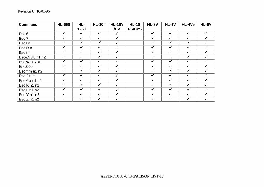
Revision C 16/01/96
APPENDIX A -COMPALISON LIST-13
Command HL-660 HL-1260
HL-10h HL-10V/DV
HL-10PS/DPS
HL-8V HL-4V HL-4Ve HL-6V
Esc 6 ü ü ü ü ü ü ü ü
Esc 7 ü ü ü ü ü ü ü ü
Esc l n ü ü ü ü ü ü ü ü
Esc R n ü ü ü ü ü ü ü ü
Esc t n ü ü ü ü ü ü ü ü
Esc&NUL n1 n2 ü ü ü ü ü ü ü ü
Esc % n NUL ü ü ü ü ü ü ü ü
Esc:000 ü ü ü ü ü ü ü ü
Esc * m n1 n2 ü ü ü ü ü ü ü ü
Esc ? n m ü ü ü ü ü ü ü ü
Esc ^ a n1 n2 ü ü ü ü ü ü ü ü
Esc K n1 n2 ü ü ü ü ü ü ü ü
Esc L n1 n2 ü ü ü ü ü ü ü ü
Esc Y n1 n2 ü ü ü ü ü ü ü ü
Esc Z n1 n2 ü ü ü ü ü ü ü ü
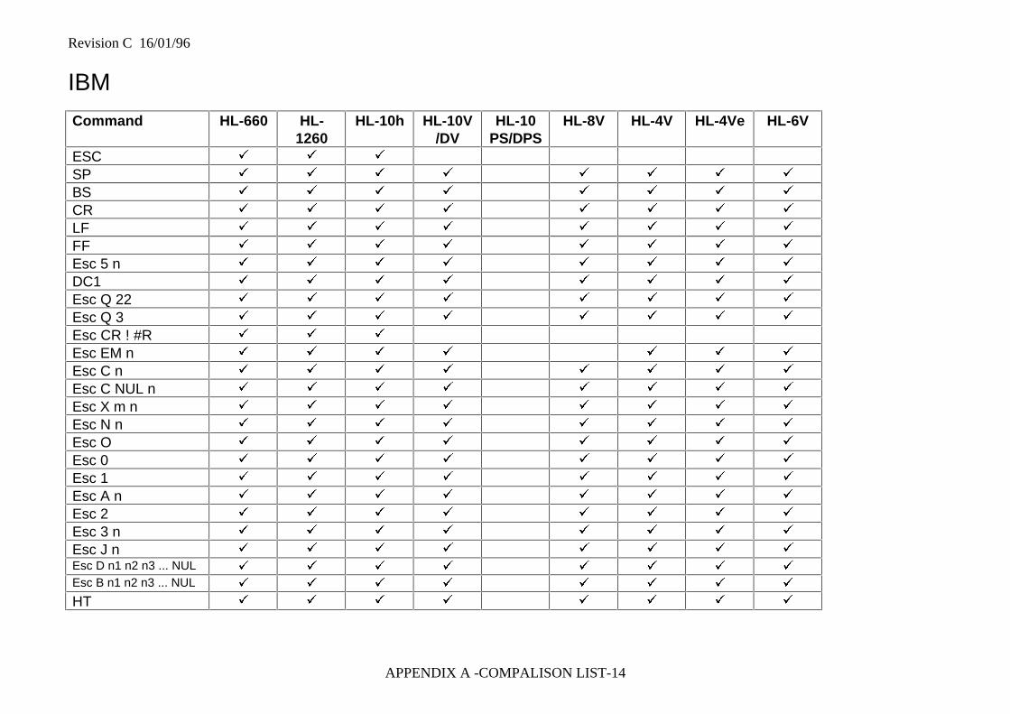
Revision C 16/01/96
APPENDIX A -COMPALISON LIST-14
IBM
Command HL-660 HL-1260
HL-10h HL-10V/DV
HL-10PS/DPS
HL-8V HL-4V HL-4Ve HL-6V
ESC ü ü ü
SP ü ü ü ü ü ü ü ü
BS ü ü ü ü ü ü ü ü
CR ü ü ü ü ü ü ü ü
LF ü ü ü ü ü ü ü ü
FF ü ü ü ü ü ü ü ü
Esc 5 n ü ü ü ü ü ü ü ü
DC1 ü ü ü ü ü ü ü ü
Esc Q 22 ü ü ü ü ü ü ü ü
Esc Q 3 ü ü ü ü ü ü ü ü
Esc CR ! #R ü ü ü
Esc EM n ü ü ü ü ü ü ü
Esc C n ü ü ü ü ü ü ü ü
Esc C NUL n ü ü ü ü ü ü ü ü
Esc X m n ü ü ü ü ü ü ü ü
Esc N n ü ü ü ü ü ü ü ü
Esc O ü ü ü ü ü ü ü ü
Esc 0 ü ü ü ü ü ü ü ü
Esc 1 ü ü ü ü ü ü ü ü
Esc A n ü ü ü ü ü ü ü ü
Esc 2 ü ü ü ü ü ü ü ü
Esc 3 n ü ü ü ü ü ü ü ü
Esc J n ü ü ü ü ü ü ü ü
Esc D n1 n2 n3 ... NUL ü ü ü ü ü ü ü ü
Esc B n1 n2 n3 ... NUL ü ü ü ü ü ü ü ü
HT ü ü ü ü ü ü ü ü
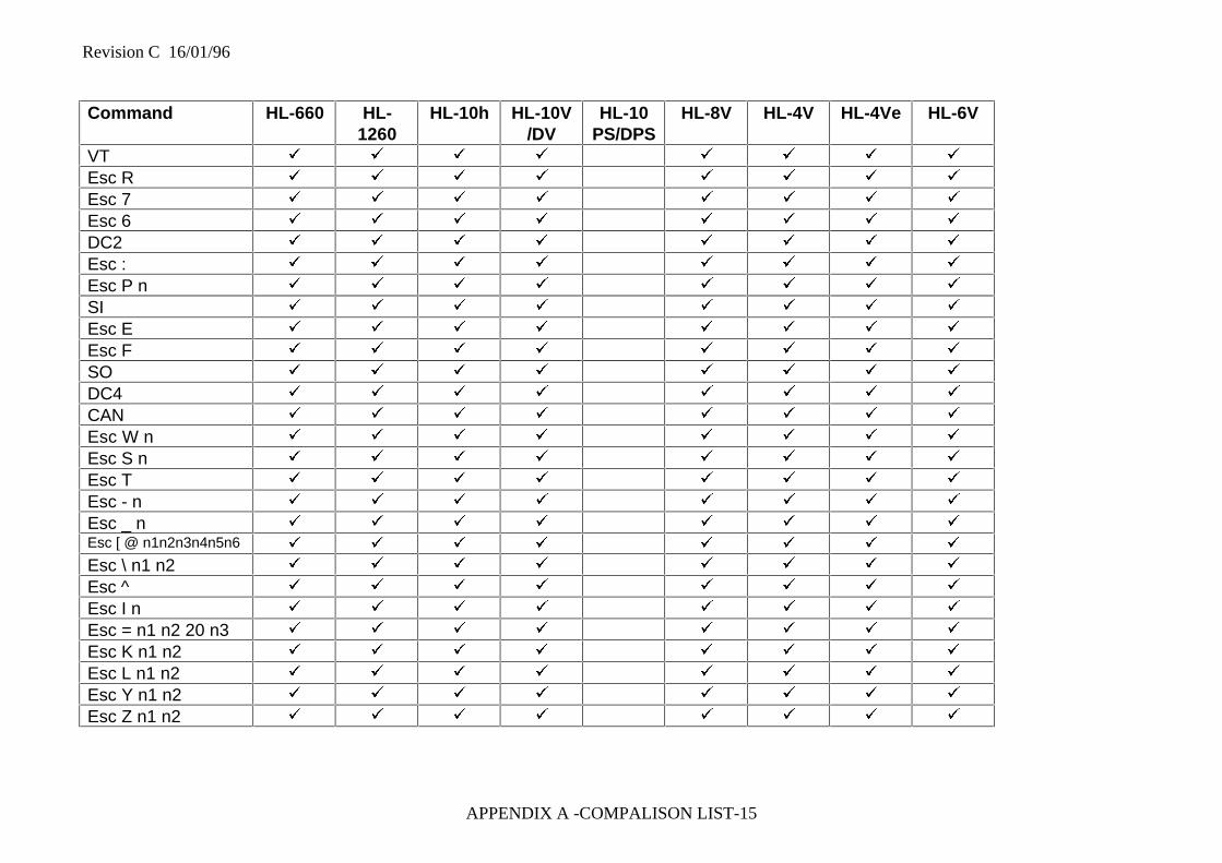
Revision C 16/01/96
APPENDIX A -COMPALISON LIST-15
Command HL-660 HL-1260
HL-10h HL-10V/DV
HL-10PS/DPS
HL-8V HL-4V HL-4Ve HL-6V
VT ü ü ü ü ü ü ü ü
Esc R ü ü ü ü ü ü ü ü
Esc 7 ü ü ü ü ü ü ü ü
Esc 6 ü ü ü ü ü ü ü ü
DC2 ü ü ü ü ü ü ü ü
Esc : ü ü ü ü ü ü ü ü
Esc P n ü ü ü ü ü ü ü ü
SI ü ü ü ü ü ü ü ü
Esc E ü ü ü ü ü ü ü ü
Esc F ü ü ü ü ü ü ü ü
SO ü ü ü ü ü ü ü ü
DC4 ü ü ü ü ü ü ü ü
CAN ü ü ü ü ü ü ü ü
Esc W n ü ü ü ü ü ü ü ü
Esc S n ü ü ü ü ü ü ü ü
Esc T ü ü ü ü ü ü ü ü
Esc - n ü ü ü ü ü ü ü ü
Esc _ n ü ü ü ü ü ü ü ü
Esc [ @ n1n2n3n4n5n6 ü ü ü ü ü ü ü ü
Esc \ n1 n2 ü ü ü ü ü ü ü ü
Esc ^ ü ü ü ü ü ü ü ü
Esc I n ü ü ü ü ü ü ü ü
Esc = n1 n2 20 n3 ü ü ü ü ü ü ü ü
Esc K n1 n2 ü ü ü ü ü ü ü ü
Esc L n1 n2 ü ü ü ü ü ü ü ü
Esc Y n1 n2 ü ü ü ü ü ü ü ü
Esc Z n1 n2 ü ü ü ü ü ü ü ü
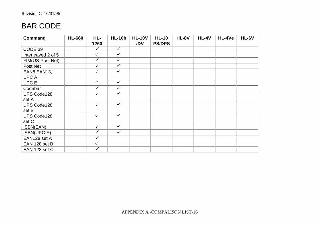
Revision C 16/01/96
APPENDIX A -COMPALISON LIST-16
BAR CODE
Command HL-660 HL-1260
HL-10h HL-10V/DV
HL-10PS/DPS
HL-8V HL-4V HL-4Ve HL-6V
CODE 39 ü ü
Interleaved 2 of 5 ü ü
FIM(US-Post Net) ü ü
Post Net ü ü
EAN8,EAN13,UPC A
ü ü
UPC E ü ü
Codabar ü ü
UPS Code128set A
ü ü
UPS Code128set B
ü ü
UPS Code128set C
ü ü
ISBN(EAN) ü ü
ISBN(UPC-E) ü ü
EAN128 set A ü
EAN 128 set B ü
EAN 128 set C ü
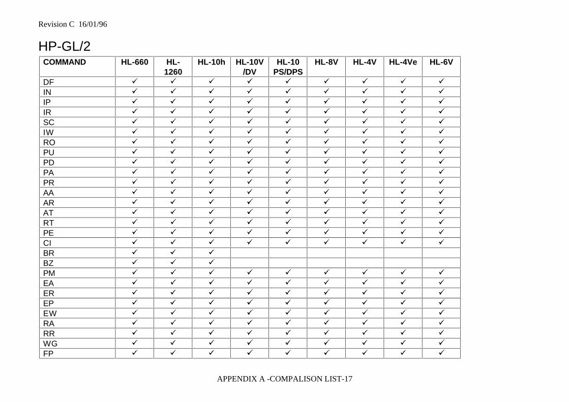
Revision C 16/01/96
APPENDIX A -COMPALISON LIST-17
HP-GL/2COMMAND HL-660 HL-
1260HL-10h HL-10V
/DVHL-10
PS/DPSHL-8V HL-4V HL-4Ve HL-6V
DF ü ü ü ü ü ü ü ü ü
IN ü ü ü ü ü ü ü ü ü
IP ü ü ü ü ü ü ü ü ü
IR ü ü ü ü ü ü ü ü ü
SC ü ü ü ü ü ü ü ü ü
IW ü ü ü ü ü ü ü ü ü
RO ü ü ü ü ü ü ü ü ü
PU ü ü ü ü ü ü ü ü ü
PD ü ü ü ü ü ü ü ü ü
PA ü ü ü ü ü ü ü ü ü
PR ü ü ü ü ü ü ü ü ü
AA ü ü ü ü ü ü ü ü ü
AR ü ü ü ü ü ü ü ü ü
AT ü ü ü ü ü ü ü ü ü
RT ü ü ü ü ü ü ü ü ü
PE ü ü ü ü ü ü ü ü ü
CI ü ü ü ü ü ü ü ü ü
BR ü ü ü
BZ ü ü ü
PM ü ü ü ü ü ü ü ü ü
EA ü ü ü ü ü ü ü ü ü
ER ü ü ü ü ü ü ü ü ü
EP ü ü ü ü ü ü ü ü ü
EW ü ü ü ü ü ü ü ü ü
RA ü ü ü ü ü ü ü ü ü
RR ü ü ü ü ü ü ü ü ü
WG ü ü ü ü ü ü ü ü ü
FP ü ü ü ü ü ü ü ü ü
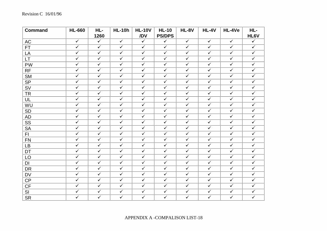
Revision C 16/01/96
APPENDIX A -COMPALISON LIST-18
Command HL-660 HL-1260
HL-10h HL-10V/DV
HL-10PS/DPS
HL-8V HL-4V HL-4Ve HL-HL6V
AC ü ü ü ü ü ü ü ü ü
FT ü ü ü ü ü ü ü ü ü
LA ü ü ü ü ü ü ü ü ü
LT ü ü ü ü ü ü ü ü ü
PW ü ü ü ü ü ü ü ü ü
RF ü ü ü ü ü ü ü ü ü
SM ü ü ü ü ü ü ü ü ü
SP ü ü ü ü ü ü ü ü ü
SV ü ü ü ü ü ü ü ü ü
TR ü ü ü ü ü ü ü ü ü
UL ü ü ü ü ü ü ü ü ü
WU ü ü ü ü ü ü ü ü ü
SD ü ü ü ü ü ü ü ü ü
AD ü ü ü ü ü ü ü ü ü
SS ü ü ü ü ü ü ü ü ü
SA ü ü ü ü ü ü ü ü ü
FI ü ü ü ü ü ü ü ü ü
FN ü ü ü ü ü ü ü ü ü
LB ü ü ü ü ü ü ü ü ü
DT ü ü ü ü ü ü ü ü ü
LO ü ü ü ü ü ü ü ü ü
DI ü ü ü ü ü ü ü ü ü
DR ü ü ü ü ü ü ü ü ü
DV ü ü ü ü ü ü ü ü ü
CP ü ü ü ü ü ü ü ü ü
CF ü ü ü ü ü ü ü ü ü
SI ü ü ü ü ü ü ü ü ü
SR ü ü ü ü ü ü ü ü ü
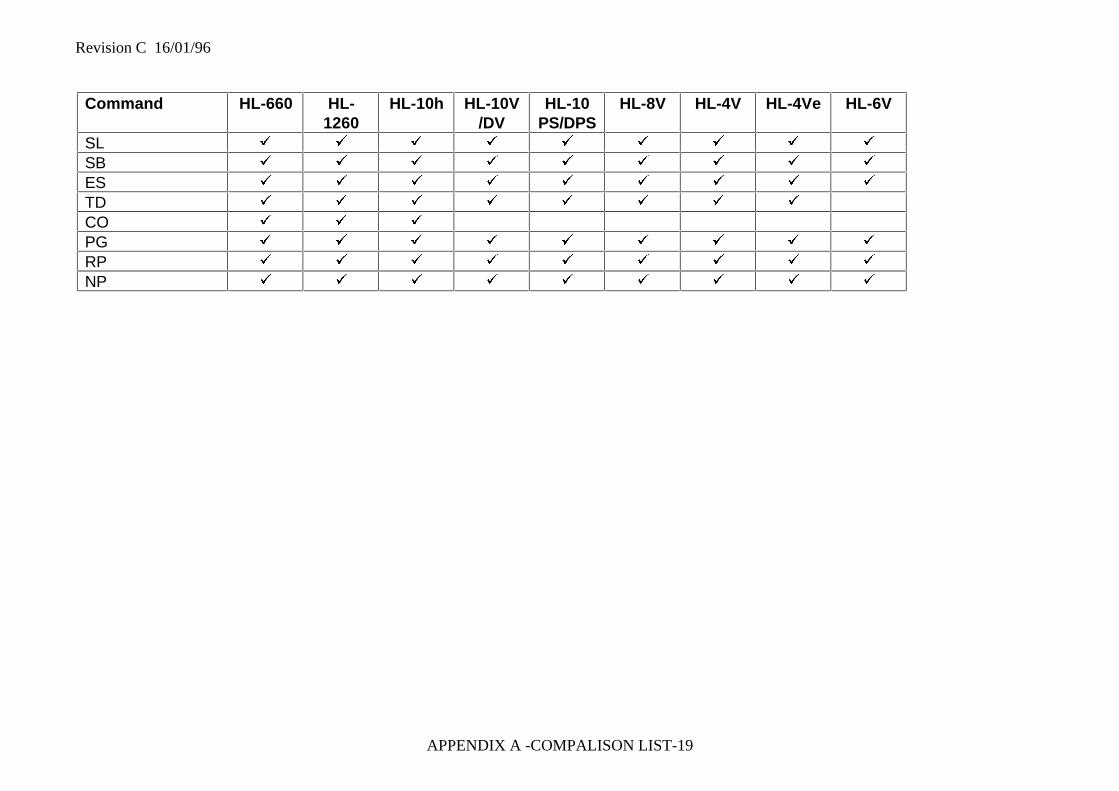
Revision C 16/01/96
APPENDIX A -COMPALISON LIST-19
Command HL-660 HL-1260
HL-10h HL-10V/DV
HL-10PS/DPS
HL-8V HL-4V HL-4Ve HL-6V
SL ü ü ü ü ü ü ü ü ü
SB ü ü ü ü ü ü ü ü ü
ES ü ü ü ü ü ü ü ü ü
TD ü ü ü ü ü ü ü ü
CO ü ü ü
PG ü ü ü ü ü ü ü ü ü
RP ü ü ü ü ü ü ü ü ü
NP ü ü ü ü ü ü ü ü ü
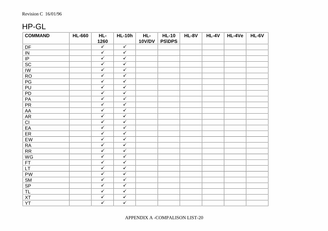
Revision C 16/01/96
APPENDIX A -COMPALISON LIST-20
HP-GLCOMMAND HL-660 HL-
1260HL-10h HL-
10V/DVHL-10
PS\DPSHL-8V HL-4V HL-4Ve HL-6V
DF ü ü
IN ü ü
IP ü ü
SC ü ü
IW ü ü
RO ü ü
PG ü ü
PU ü ü
PD ü ü
PA ü ü
PR ü ü
AA ü ü
AR ü ü
CI ü ü
EA ü ü
ER ü ü
EW ü ü
RA ü ü
RR ü ü
WG ü ü
FT ü ü
LT ü ü
PW ü ü
SM ü ü
SP ü ü
TL ü ü
XT ü ü
YT ü ü
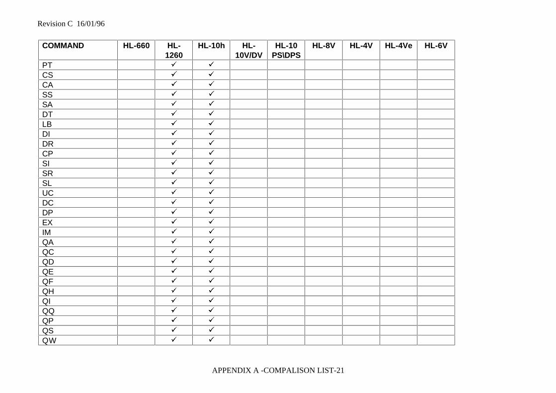
Revision C 16/01/96
APPENDIX A -COMPALISON LIST-21
COMMAND HL-660 HL-1260
HL-10h HL-10V/DV
HL-10PS\DPS
HL-8V HL-4V HL-4Ve HL-6V
PT ü ü
CS ü ü
CA ü ü
SS ü ü
SA ü ü
DT ü ü
LB ü ü
DI ü ü
DR ü ü
CP ü ü
SI ü ü
SR ü ü
SL ü ü
UC ü ü
DC ü ü
DP ü ü
EX ü ü
IM ü ü
QA ü ü
QC ü ü
QD ü ü
QE ü ü
QF ü ü
QH ü ü
QI ü ü
QQ ü ü
QP ü ü
QS ü ü
QW ü ü
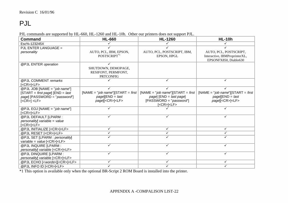
Revision C 16/01/96
APPENDIX A -COMPALISON LIST-22
PJLPJL commands are supported by HL-660, HL-1260 and HL-10h. Other our printers does not support PJL.Command HL-660 HL-1260 HL-10hEsc%-123245X ü ü ü
PJL ENTER LANGUAGE =personality
ü
AUTO, PCL, IBM, EPSON,POSTSCRIPT*1
ü
AUTO, PCL, POSTSCRIPT, IBM,EPSON, HPGL
ü
AUTO, PCL, POSTSCRIPT,Interactive, IBMProprinterXL,
EPSONFX850, Diablo630@PJL ENTER operation ü
SHUTDOWN, DEMOPAGE,RESIFONT, PERMFONT,
PRTCONFIG@PJL COMMENT remarks[<CR>]<LF>
ü ü ü
@PJL JOB [NAME = "job name"][START = first page] [END = lastpage] [PASSWORD = "password"][<CR>] <LF>
ü
[NAME = "job name"][START = firstpage][END = lastpage][<CR>]<LF>
ü
[NAME = "job name"][START = firstpage] [END = last page]
[PASSWORD = "password"][<CR>]<LF>
ü
[NAME = "job name"][START = firstpage][END = lastpage][<CR>]<LF>
@PJL EOJ [NAME = "job name"][<CR>]<LF>
ü ü ü
@PJL DEFAULT [LPARM :personality] variable = value[<CR>]<LF>
ü ü ü
@PJL INITIALIZE [<CR>]<LF> ü ü ü
@PJL RESET [<CR>]<LF> ü ü ü
@PJL SET [LPARM : personality]variable = value [<CR>]<LF>
ü ü ü
@PJL INQUIRE [LPARM :personality] variable [<CR>]<LF>
ü ü ü
@PJL DINQUIRE [LPARM :personality] variable [<CR>]<LF>
ü ü ü
@PJL ECHO [<words>][<CR>]<LF> ü ü ü
@PJL INFO ID [<CR>]<LF> ü ü ü
*1 This option is available only when the optional BR-Script 2 ROM Board is installed into the printer.
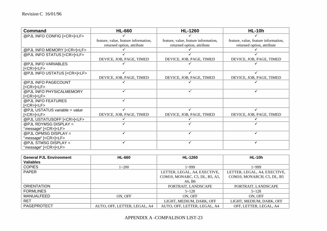
Revision C 16/01/96
APPENDIX A -COMPALISON LIST-23
Command HL-660 HL-1260 HL-10h@PJL INFO CONFIG [<CR>]<LF> ü
feature, value, feature information,returned option, attribute
ü
feature, value, feature information,returned option, attribute
ü
feature, value, feature information,returned option, attribute
@PJL INFO MEMORY [<CR>]<LF> ü ü ü
@PJL INFO STATUS [<CR>]<LF> ü
DEVICE, JOB, PAGE, TIMEDü
DEVICE, JOB, PAGE, TIMEDü
DEVICE, JOB, PAGE, TIMED@PJL INFO VARIABLES[<CR>]<LF>
ü ü ü
@PJL INFO USTATUS [<CR>]<LF> ü
DEVICE, JOB, PAGE, TIMEDü
DEVICE, JOB, PAGE, TIMEDü
DEVICE, JOB, PAGE, TIMED@PJL INFO PAGECOUNT[<CR>]<LF>
ü ü ü
@PJL INFO PHYSICALMEMORY[<CR>]<LF>
ü ü ü
@PJL INFO FEATURES[<CR>]<LF>
ü
@PJL USTATUS variable = value[<CR>]<LF>
ü
DEVICE, JOB, PAGE, TIMEDü
DEVICE, JOB, PAGE, TIMEDü
DEVICE, JOB, PAGE, TIMED@PJL USTATUSOFF [<CR>]<LF> ü ü ü
@PJL RDYMSG DISPLAY ="message" [<CR>]<LF>
ü ü ü
@PJL OPMSG DISPLAY ="message" [<CR>]<LF>
ü ü ü
@PJL STMSG DISPLAY ="message" [<CR>]<LF>
ü ü ü
General PJL EnvironmentValiables
HL-660 HL-1260 HL-10h
COPIES 1~200 1~999 1~999PAPER LETTER, LEGAL, A4, EXECTIVE,
COM10, MONARC, C5, DL, B5, A5,A6, B6
LETTER, LEGAL, A4, EXECTIVE,COM10, MONARCH, C5, DL, B5
ORIENTATION PORTRAIT, LANDSCAPE PORTRAIT, LANDSCAPEFORMLINES 5~128 5~128MANUALFEED ON, OFF ON, OFF ON, OFFRET LIGHT, MEDIUM, DARK, OFF LIGHT, MEDIUM, DARK, OFFPAGEPROTECT AUTO, OFF, LETTER, LEGAL, A4 AUTO, OFF, LETTER, LEGAL, A4 OFF, LETTER, LEGAL, A4
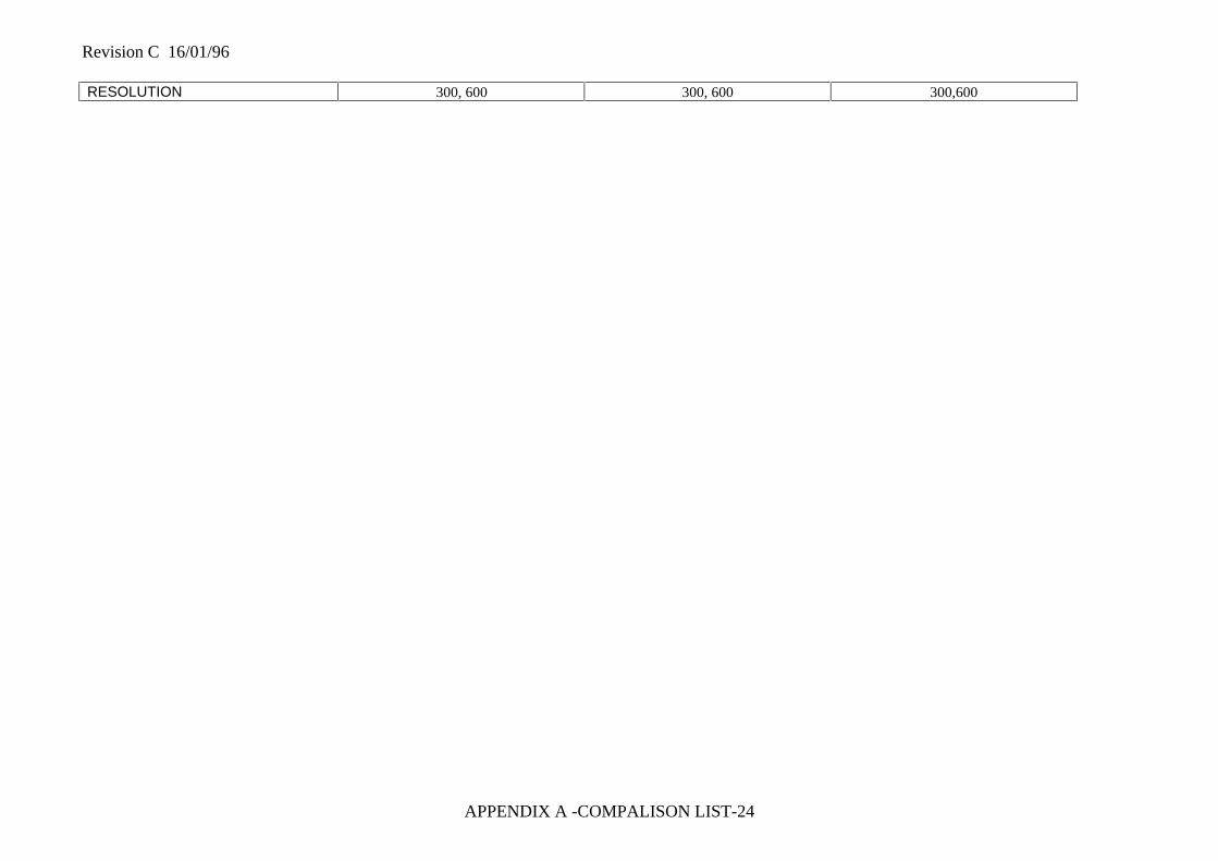
Revision C 16/01/96
APPENDIX A -COMPALISON LIST-24
RESOLUTION 300, 600 300, 600 300,600
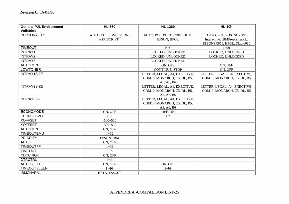
Revision C 16/01/96
APPENDIX A -COMPALISON LIST-25
General PJL EnvironmentValiables
HL-660 HL-1260 HL-10h
PERSONALITY AUTO, PCL, IBM, EPSON,POSTSCRIPT*2
AUTO, PCL, POSTSCRIPT, IBM,EPSON, HPGL
AUTO, PCL, POSTSCRIPT,Interactive, IBMProprinterXL,
EPSONFX850, HPGL, Diablo630TIMEOUT 1~99 1~99INTRAY1 LOCKED, UNLOCKED LOCKED, UNLOCKEDINTRAY2 LOCKED, UNLOCKED LOCKED, UNLOCKEDINTRAY3 LOCKED, UNLOCKEDAUTOCONT ON, OFF ON, OFFLOWTONER CONTINUE, STOP ON, OFFINTRAY1SIZE LETTER, LEGAL, A4, EXECTIVE,
COM10, MONARCH, C5, DL, B5,A5, A6, B6
LETTER, LEGAL, A4, EXECTIVE,COM10, MONARCH, C5, DL, B5
INTRAY2SIZE LETTER, LEGAL, A4, EXECTIVE,COM10, MONARCH, C5, DL, B5,
A5, A6, B6
LETTER, LEGAL, A4, EXECTIVE,COM10, MONARCH, C5, DL, B5
INTRAY3SIZE LETTER, LEGAL, A4, EXECTIVE,COM10, MONARCH, C5, DL, B5,
A5, A6, B6ECONOMODE ON, OFF OFF, ONECONOLEVEL 1~3 1,2XOFFSET -500~500YOFFSET -500~500AUTOCONT ON, OFFTIMEOUTEMU 1~99PRIORITY EPSON, IBMAUTOFF ON, OFFTIMEOUTFF 1~99TIMEOUT 1~99CDCCHIGH ON, OFFDTRCTRL 0~2AUTOSLEEP ON, OFF ON, OFFTIMEOUTSLEEP 1 ~99 1~99IBMCHARA1 BETA, ESSZET
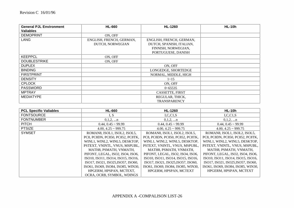
Revision C 16/01/96
APPENDIX A -COMPALISON LIST-26
General PJL EnvironmentValiables
HL-660 HL-1260 HL-10h
DEMOPRINT ON, OFFLANG ENGLISH, FRENCH, GERMAN,
DUTCH, NORWEGIANENGLISH, FRENCH, GERMAN,DUTCH, SPANISH, ITALIAN,
FINNISH, NORWEGIAN,PORTUGUESE, DANISH
KEEPPCL ON, OFFDOUBLESTRIKE ON, OFFDUPLEX ON, OFFBINDING LONGEDGE, SHORTEDGEFIRSTPRINT NORMAL, MIDDLE, HIGHDENSITY 1~15CPLOCK ON, OFFPASSWORD 0~65535MPTRAY CASSETTE, FIRSTMEDIATYPE REGULAR, THICK,
TRANSPARENCY
PCL Specific Valiables HL-660 HL-1260 HL-10hFONTSOURCE I, S I,C,C1,S I,C,C1,SFONTNUMBER 0,1,2, ...n 0,1,2, ...n 0,1,2, ...nPITCH 0.44, 0.45 ~ 99.99 0.44, 0.45 ~ 99.99 0.44, 0.45 ~ 99.99PTSIZE 4.00, 4.25 ~ 999.75 4.00, 4.25 ~ 999.75 4.00, 4.25 ~ 999.75SYMSET ROMAN8, ISOL1, ISOL2, ISOL5,
PC8, PC8DN, PC850, PC852, PC8TK,WINL1, WINL2, WINL5, DESKTOP,PSTEXT, VNINTL, VNUS, MSPUBL,
MATH8, PSMATH, VNMATH,PIFONT, LEGAL, ISO2, ISO4, ISO6,ISO10, ISO11, ISO14, ISO15, ISO16,ISO17, ISO21, ISO25,ISO57, ISO60,
ISO61, ISO69, ISO84, ISO85, WIN30,HPGERM, HPSPAN, MCTEXT,
OCRA, OCRB, SYMBOL, WDINGS
ROMAN8, ISOL1, ISOL2, ISOL5,PC8, PC8DN, PC850, PC852, PC8TK,WINL1, WINL2, WINL5, DESKTOP,PSTEXT, VNINTL, VNUS, MSPUBL,
MATH8, PSMATH, VNMATH,PIFONT, LEGAL, ISO2, ISO4, ISO6,ISO10, ISO11, ISO14, ISO15, ISO16,ISO17, ISO21, ISO25,ISO57, ISO60,
ISO61, ISO69, ISO84, ISO85, WIN30,HPGERM, HPSPAN, MCTEXT
ROMAN8, ISOL1, ISOL2, ISOL5,PC8, PC8DN, PC850, PC852, PC8TK,WINL1, WINL2, WINL5, DESKTOP,PSTEXT, VNINTL, VNUS, MSPUBL,
MATH8, PSMATH, VNMATH,PIFONT, LEGAL, ISO2, ISO4, ISO6,ISO10, ISO11, ISO14, ISO15, ISO16,ISO17, ISO21, ISO25,ISO57, ISO60,
ISO61, ISO69, ISO84, ISO85, WIN30,HPGERM, HPSPAN, MCTEXT
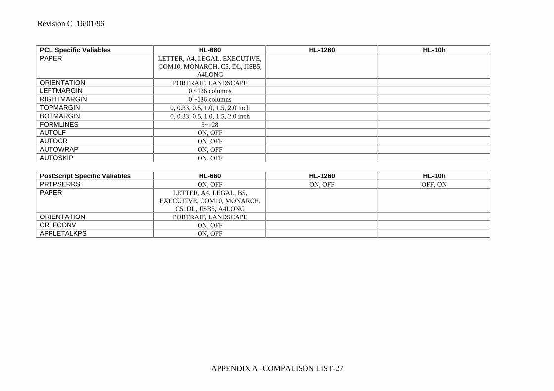
Revision C 16/01/96
APPENDIX A -COMPALISON LIST-27
PCL Specific Valiables HL-660 HL-1260 HL-10hPAPER LETTER, A4, LEGAL, EXECUTIVE,
COM10, MONARCH, C5, DL, JISB5,A4LONG
ORIENTATION PORTRAIT, LANDSCAPELEFTMARGIN 0 ~126 columnsRIGHTMARGIN 0 ~136 columnsTOPMARGIN 0, 0.33, 0.5, 1.0, 1.5, 2.0 inchBOTMARGIN 0, 0.33, 0.5, 1.0, 1.5, 2.0 inchFORMLINES 5~128AUTOLF ON, OFFAUTOCR ON, OFFAUTOWRAP ON, OFFAUTOSKIP ON, OFF
PostScript Specific Valiables HL-660 HL-1260 HL-10hPRTPSERRS ON, OFF ON, OFF OFF, ONPAPER LETTER, A4, LEGAL, B5,
EXECUTIVE, COM10, MONARCH,C5, DL, JISB5, A4LONG
ORIENTATION PORTRAIT, LANDSCAPECRLFCONV ON, OFFAPPLETALKPS ON, OFF
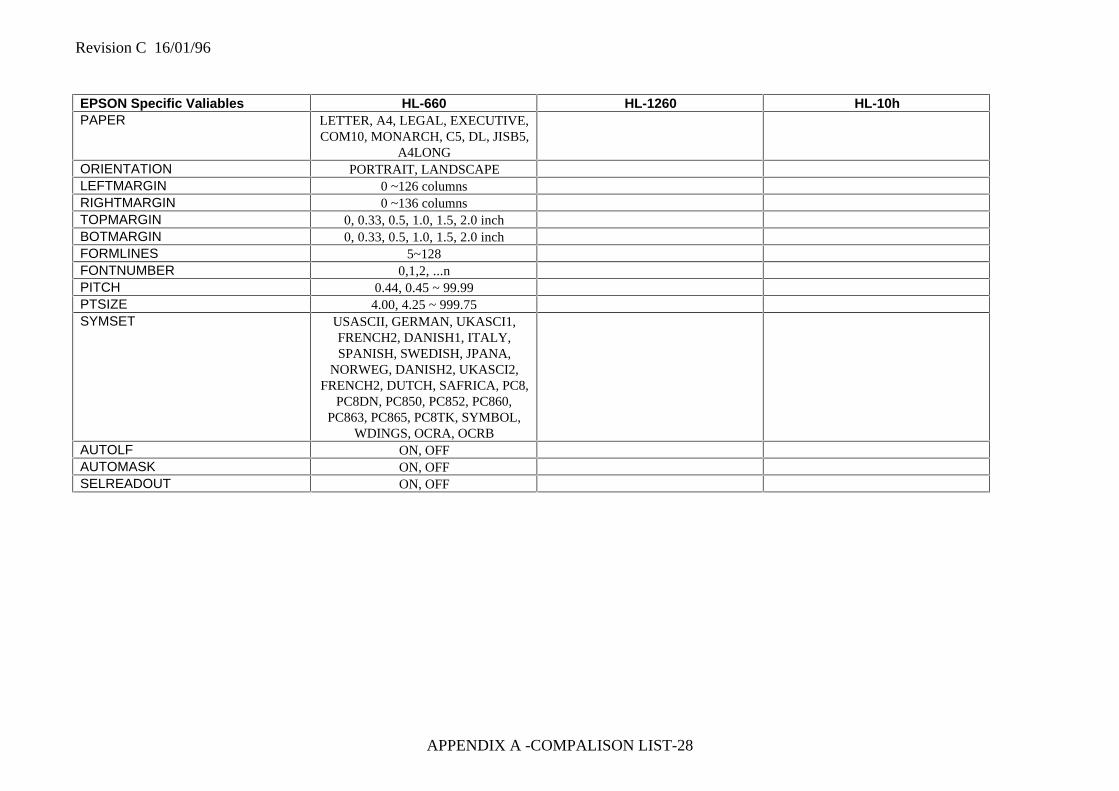
Revision C 16/01/96
APPENDIX A -COMPALISON LIST-28
EPSON Specific Valiables HL-660 HL-1260 HL-10hPAPER LETTER, A4, LEGAL, EXECUTIVE,
COM10, MONARCH, C5, DL, JISB5,A4LONG
ORIENTATION PORTRAIT, LANDSCAPELEFTMARGIN 0 ~126 columnsRIGHTMARGIN 0 ~136 columnsTOPMARGIN 0, 0.33, 0.5, 1.0, 1.5, 2.0 inchBOTMARGIN 0, 0.33, 0.5, 1.0, 1.5, 2.0 inchFORMLINES 5~128FONTNUMBER 0,1,2, ...nPITCH 0.44, 0.45 ~ 99.99PTSIZE 4.00, 4.25 ~ 999.75SYMSET USASCII, GERMAN, UKASCI1,
FRENCH2, DANISH1, ITALY,SPANISH, SWEDISH, JPANA,
NORWEG, DANISH2, UKASCI2,FRENCH2, DUTCH, SAFRICA, PC8,
PC8DN, PC850, PC852, PC860,PC863, PC865, PC8TK, SYMBOL,
WDINGS, OCRA, OCRBAUTOLF ON, OFFAUTOMASK ON, OFFSELREADOUT ON, OFF
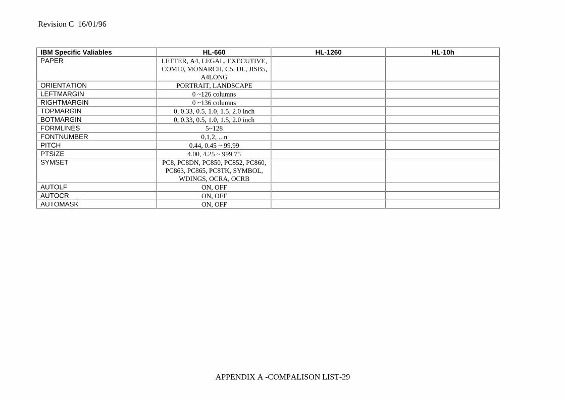
Revision C 16/01/96
APPENDIX A -COMPALISON LIST-29
IBM Specific Valiables HL-660 HL-1260 HL-10hPAPER LETTER, A4, LEGAL, EXECUTIVE,
COM10, MONARCH, C5, DL, JISB5,A4LONG
ORIENTATION PORTRAIT, LANDSCAPELEFTMARGIN 0 ~126 columnsRIGHTMARGIN 0 ~136 columnsTOPMARGIN 0, 0.33, 0.5, 1.0, 1.5, 2.0 inchBOTMARGIN 0, 0.33, 0.5, 1.0, 1.5, 2.0 inchFORMLINES 5~128FONTNUMBER 0,1,2, ...nPITCH 0.44, 0.45 ~ 99.99PTSIZE 4.00, 4.25 ~ 999.75SYMSET PC8, PC8DN, PC850, PC852, PC860,
PC863, PC865, PC8TK, SYMBOL,WDINGS, OCRA, OCRB
AUTOLF ON, OFFAUTOCR ON, OFFAUTOMASK ON, OFF