Brother Advanced Document Scanner SERVICE … Brother Advanced Document Scanner SERVICE MANUAL...
135
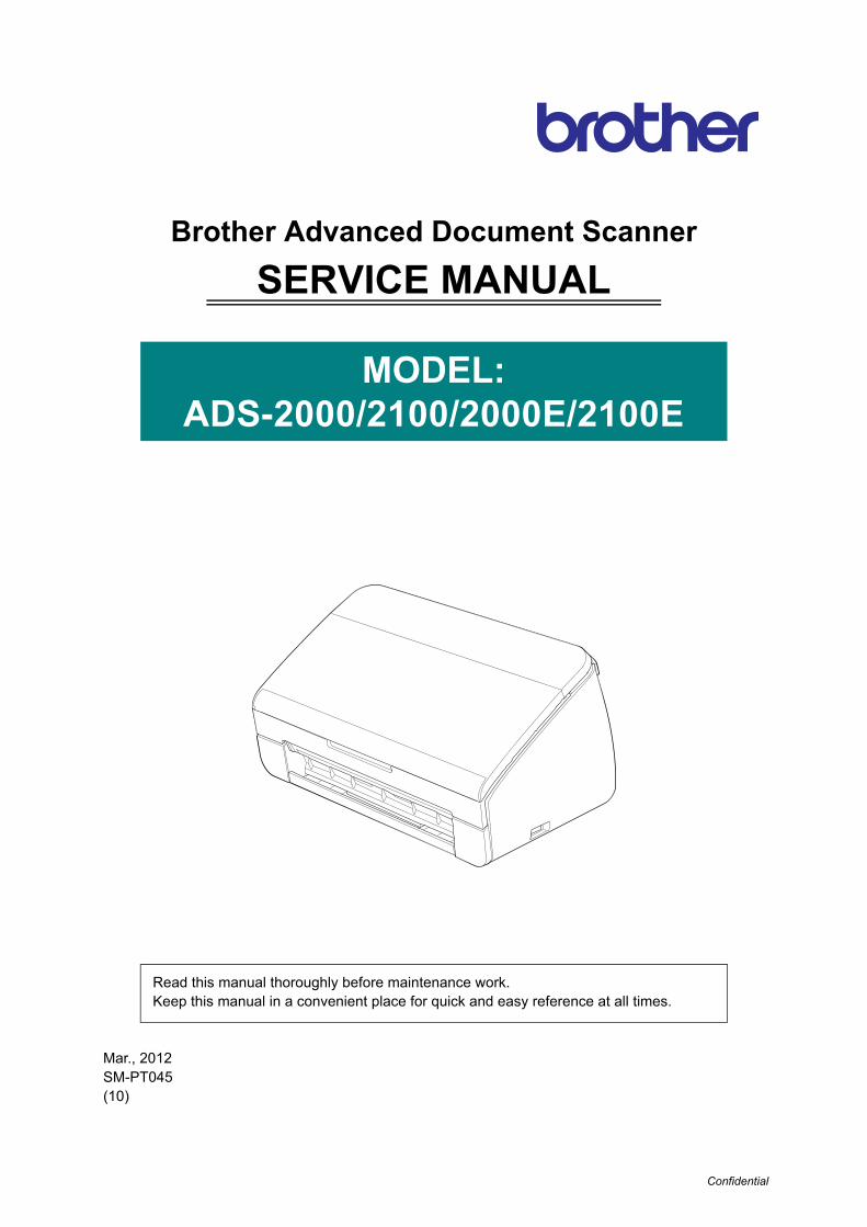
Confidential Brother Advanced Document Scanner SERVICE MANUAL MODEL: ADS-2000/2100/2000E/2100E Read this manual thoroughly before maintenance work. Keep this manual in a convenient place for quick and easy reference at all times. Mar., 2012 SM-PT045 (10)
Transcript of Brother Advanced Document Scanner SERVICE … Brother Advanced Document Scanner SERVICE MANUAL...
Confidential
Brother Advanced Document Scanner
SERVICE MANUAL
MODEL:ADS-2000/2100/2000E/2100E
Read this manual thoroughly before maintenance work.Keep this manual in a convenient place for quick and easy reference at all times.
Mar., 2012SM-PT045(10)

Confidential
© Copyright Brother 2012
All rights reserved.
No part of this publication may be reproduced in any form or by any means without permission in writing from the publisher.
All other product and company names mentioned in this manual are trademarks or registered trademarks of their respective holders.
Specifications are subject to change without notice.

Confidential
TRADEMARKSBROTHER is either a trademark or a registered trademark of Brother Industries, Ltd.
Microsoft, Windows, Windows Vista, Windows Server, Outlook and Internet Explorer are either registered trademarks or trademarks of Microsoft Corporation in the United States and/or other countries.
Apple, Macintosh, Mac OS and Safari are trademarks of Apple Inc., registered in the United States and other countries.
Nuance, the Nuance logo, PaperPort and ScanSoft are trademarks or registered trademarks of Nuance Communications, Inc. or its affiliates in the United States and/or other countries.
PowerPC is a registered trademark of IBM in the United States and/or other countries.
AOSS is a trademark of Buffalo Inc.
WPA, WPA2, Wi-Fi Protected Access and Wi-Fi Protected Setup are marks of the Wi-Fi Alliance.
Wi-Fi and Wi-Fi Alliance are registered marks of the Wi-Fi Alliance.
AMD is a trademark of Advanced Micro Devices, Inc.
Linux is the registered trademark of Linus Torvalds in the U.S. and other countries.
Android is a trademark of Google Inc.
ISIS, Captiva and QuickScan are either registered trademarks or trademarks of EMC Corporation in the United States and/or other countries.
Intel is a trademark of Intel Corporation in the U.S. and/or other countries.
Adobe, Reader and Photoshop are either registered trademarks or trademarks of Adobe Systems Incorporated in the United States and/or other countries.
Each company whose software title is mentioned in this manual has a Software License Agreement specific to its proprietary programs.
Any trade names and product names of companies appearing on Brother products, related documents and any other materials are all trademarks or registered trademarks of those respective companies.
Copyright and License
© 2014 Brother Industries, Ltd. All rights reserved.
This product includes software developed by the following vendors:
© 1983-1998 PACIFIC SOFTWORKS, INC.
© 2008 Devicescape Software, Inc.
This product includes the “KASAGO TCP/IP” software developed by ZUKEN ELMIC,Inc.

i Confidential
CONTENTS
REGULATION ............................................................................................................ v
SAFETY INFORMATION......................................................................................... viii
CHAPTER 1 SPECIFICATIONS
1. SPECIFICATIONS LIST............................................................................................................... 1-1
1.1 General ................................................................................................................................ 1-1
1.2 Network Connectivity ........................................................................................................... 1-3
1.3 Service Information.............................................................................................................. 1-3
1.4 Consumable Parts ............................................................................................................... 1-3
1.5 Paper ................................................................................................................................... 1-4
1.5.1 Paper handling ...................................................................................................... 1-4
1.5.2 Media specifications .............................................................................................. 1-4
1.6 Scanner ............................................................................................................................... 1-4
CHAPTER 2 TROUBLESHOOTING
1. INTRODUCTION .......................................................................................................................... 2-1
1.1 Precautions.......................................................................................................................... 2-1
1.2 Checks before Commencing Troubleshooting..................................................................... 2-2
2. OVERVIEW .................................................................................................................................. 2-3
2.1 Cross-section Drawing......................................................................................................... 2-3
2.2 Paper Feeding ..................................................................................................................... 2-4
2.3 Operation of Each Part ........................................................................................................ 2-5
2.4 Block Diagram ..................................................................................................................... 2-6
2.5 Main Components................................................................................................................ 2-7
3. ERROR INDICATIONS................................................................................................................. 2-8
3.1 LED Display when an Error Occurs ..................................................................................... 2-8
3.2 Status Error Messages ...................................................................................................... 2-13
4. TROUBLESHOOTING ............................................................................................................... 2-14
4.1 Troubleshooting for Error Display ...................................................................................... 2-14
4.1.1 The double feeding sensor detected multiple documents. .................................. 2-14
4.1.2 The document scanning position sensor detected that the document length was 40 cm or more. (Document jam)................................. 2-14
4.1.3 The document scanning position sensor has not detected the top of the document even after the document has been fed for the specified distance. (Document jam)................................................................................................... 2-14
4.1.4 A non-supported USB device is connected to the USB terminal.A USB device with a built-in hub is connected to the USB terminal.A USB device not within the specifications is connected to the USB terminal, resulting in overcurrent. ....................................................................................... 2-15

ii Confidential
4.1.5 The scanned data has exceeded the built-in memory capacity. ......................... 2-15
4.1.6 The first side or second side CIS flat cable is not connected correctly. .............. 2-15
4.1.7 An error occurred during access to the DRAM in the main PCB ASSY.Program errorAn error occurred in the ROM checksum.Write error in the EEPROM of the main PCB...................................................... 2-15
4.1.8 The country code was not entered correctly. ...................................................... 2-15
4.1.9 The page counter for the separation pad has reached the limit.The page counters for both the separation pad and the pick-up roller have reached the limit.The page counter for the pick-up roller has reached the limit. ............................ 2-16
4.1.10 The front cover sensor detected an open front cover in the ready state.The front cover sensor detected an open front cover during scanning. .............. 2-16
4.1.11 Color parameter in the ROM does not match the first side or second side CIS unit. .......................................................................................... 2-16
4.1.12 A scanning error occurred while scanning the image.......................................... 2-16
4.1.13 The voltage value was below the lower limit during scanning.The white level does not increase during scanning although the light intensity was increased.A white level not within the standard was scanned when the maintenance mode function "Acquire white level data and set CIS scan area" was executed.A black level not within the standard was scanned when the maintenance mode function "Acquire white level data and set CIS scan area" was executed........... 2-17
4.2 Troubleshooting for Image Defects.................................................................................... 2-18
4.2.1 Defect examples.................................................................................................. 2-18
4.2.2 Troubleshooting according to image defect ........................................................ 2-18
4.3 Troubleshooting for Document Paper Feeding Problems.................................................. 2-22
4.3.1 Multiple documents are fed ................................................................................. 2-22
4.3.2 Document becomes wrinkled .............................................................................. 2-22
4.3.3 Document becomes jammed............................................................................... 2-23
4.3.4 Document is not picked up and fed ..................................................................... 2-24
4.4 Troubleshooting for Software Problems ............................................................................ 2-25
4.4.1 Does not respond to operation from a computer................................................. 2-25
4.4.2 Cannot read data ................................................................................................ 2-25
4.5 Troubleshooting for Control Panel Problems..................................................................... 2-26
4.5.1 Nothing is displayed on the LED ......................................................................... 2-26
4.5.2 Control panel is inoperable.................................................................................. 2-26
4.5.3 Only specified buttons are inoperable ................................................................. 2-26
4.6 Troubleshooting for Other Problems.................................................................................. 2-27
4.6.1 Machine does not turn ON .................................................................................. 2-27
4.6.2 Unusual noise is coming from the machine......................................................... 2-27
4.6.3 Data cannot be saved in the USB memory ......................................................... 2-27
CHAPTER 3 DISASSEMBLY/REASSEMBLY
1. SAFETY PRECAUTIONS............................................................................................................. 3-1
2. PACKING ..................................................................................................................................... 3-2
3. SCREW CATALOGUE................................................................................................................. 3-3
4. SCREW TORQUE LIST ............................................................................................................... 3-4

iii Confidential
5. LUBRICATION ............................................................................................................................. 3-5
6. OVERVIEW OF GEARS............................................................................................................... 3-6
7. HARNESS ROUTING................................................................................................................... 3-7
8. DISASSEMBLY FLOW CHART................................................................................................. 3-10
9. DISASSEMBLY PROCEDURE.................................................................................................. 3-11
9.1 Preparation ........................................................................................................................ 3-11
9.2 Separation pad ASSY........................................................................................................ 3-12
9.3 Pick-up roller ASSY ........................................................................................................... 3-14
9.4 Output tray ......................................................................................................................... 3-15
9.5 Side cover L....................................................................................................................... 3-16
9.6 Side cover R ...................................................................................................................... 3-16
9.7 Main PCB ASSY................................................................................................................ 3-17
9.8 USB host PCB ASSY......................................................................................................... 3-19
9.9 Front cover L/R.................................................................................................................. 3-20
9.10 Panel ASSY....................................................................................................................... 3-21
9.11 Panel PCB ASSY / Rubber key / Top cover sensor / Top cover actuator ......................... 3-23
9.12 Document detection sensor PCB / Document detection actuator /Document scanning position sensor PCB / Document scanning position actuator /Double feeding sensor (Sent) / Separation pad ASSY...................................................... 3-24
9.13 Second side CIS unit ......................................................................................................... 3-29
9.14 Top cover / Document guide LS / Document guide RS..................................................... 3-30
9.15 Back cover S...................................................................................................................... 3-31
9.16 Back cover ......................................................................................................................... 3-32
9.17 Power supply PCB ASSY .................................................................................................. 3-33
9.18 Main motor......................................................................................................................... 3-36
9.19 Front cover sensor............................................................................................................. 3-37
9.20 Double feeding sensor PCB ASSY (Receive) ................................................................... 3-38
9.21 First side CIS unit .............................................................................................................. 3-39
9.22 One way clutch .................................................................................................................. 3-40
CHAPTER 4 ADJUSTING AND UPDATING SETTINGS AS REQUIRED AFTER PARTS REPLACEMENT
1. IF YOU REPLACE THE MAIN PCB ASSY.................................................................................. 4-1
1.1 Installing Firmware............................................................................................................... 4-2
1.1.1 Checking firmware version .................................................................................... 4-2
1.1.2 Installing firmware ................................................................................................. 4-3
1.2 Setting by Country ............................................................................................................... 4-4
1.3 Initializing the EEPROM of the Main PCB ASSY................................................................. 4-4
1.4 Setting Serial Number.......................................................................................................... 4-5
1.5 Acquiring White Level Data ................................................................................................. 4-6
1.6 Setting Double Feeding Sensor Threshold.......................................................................... 4-7
iv Confidential
1.7 Checking Operation after Repair ......................................................................................... 4-8
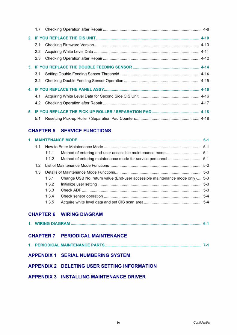
2. IF YOU REPLACE THE CIS UNIT ............................................................................................. 4-10
2.1 Checking Firmware Version............................................................................................... 4-10
2.2 Acquiring White Level Data ............................................................................................... 4-11
2.3 Checking Operation after Repair ....................................................................................... 4-12
3. IF YOU REPLACE THE DOUBLE FEEDING SENSOR ............................................................ 4-14
3.1 Setting Double Feeding Sensor Threshold........................................................................ 4-14
3.2 Checking Double Feeding Sensor Operation .................................................................... 4-15
4. IF YOU REPLACE THE PANEL ASSY...................................................................................... 4-16
4.1 Acquiring White Level Data for Second Side CIS Unit ...................................................... 4-16
4.2 Checking Operation after Repair ....................................................................................... 4-17
5. IF YOU REPLACE THE PICK-UP ROLLER / SEPARATION PAD........................................... 4-18
5.1 Resetting Pick-up Roller / Separation Pad Counters......................................................... 4-18
CHAPTER 5 SERVICE FUNCTIONS
1. MAINTENANCE MODE................................................................................................................ 5-1
1.1 How to Enter Maintenance Mode ........................................................................................ 5-1
1.1.1 Method of entering end-user accessible maintenance mode................................ 5-1
1.1.2 Method of entering maintenance mode for service personnel .............................. 5-1
1.2 List of Maintenance Mode Functions ................................................................................... 5-2
1.3 Details of Maintenance Mode Functions.............................................................................. 5-3
1.3.1 Change USB No. return value (End-user accessible maintenance mode only) .... 5-3
1.3.2 Initialize user setting.............................................................................................. 5-3
1.3.3 Check ADF ............................................................................................................ 5-3
1.3.4 Check sensor operation ........................................................................................ 5-4
1.3.5 Acquire white level data and set CIS scan area.................................................... 5-4
CHAPTER 6 WIRING DIAGRAM
1. WIRING DIAGRAM ...................................................................................................................... 6-1
CHAPTER 7 PERIODICAL MAINTENANCE
1. PERIODICAL MAINTENANCE PARTS....................................................................................... 7-1
APPENDIX 1 SERIAL NUMBERING SYSTEM
APPENDIX 2 DELETING USER SETTING INFORMATION
APPENDIX 3 INSTALLING MAINTENANCE DRIVER
v Confidential
REGULATION
Declaration of Conformity (Europe only) We, Brother Industries, Ltd.
15-1 Naeshiro-cho, Mizuho-ku, Nagoya 467-8561 Japan declare that this product is in conformity with the essential requirements of all relevant directives and regulations applied within the European Community.
The Declaration of Conformity (DoC) can be downloaded from Brother Solutions Center. Visit http://support.brother.com/ and:
• select “Europe”
• select your country
• select your model
• select “Manuals”
Your Declaration will be downloaded as a PDF file.
Wiring Information (U.K. only)
If you need to replace the plug fuse, fit a fuse that is approved by ASTA to BS1362 with the same rating as the original fuse.
Always replace the fuse cover. Never use a plug that does not have a cover. If in any doubt, call a qualified electrician.
Warning -This product must be earthed.
The wires in the mains lead are coloured in line with the following code:
• Green and Yellow: Earth
• Blue: Neutral
• Brown: Live
Radio Interference
This product complies with EN55022 (CISPR Publication 22)/Class B. When connecting the machine to a computer, ensure that you use a USB cable which does not exceed 2 m in length.
WARNING
• Use only the power cord supplied with this machine.
• This product must be installed near an electrical socket that is easily accessible. In case of emergencies, you must unplug the power cord from the electrical socket to shut off power completely.
vi Confidential
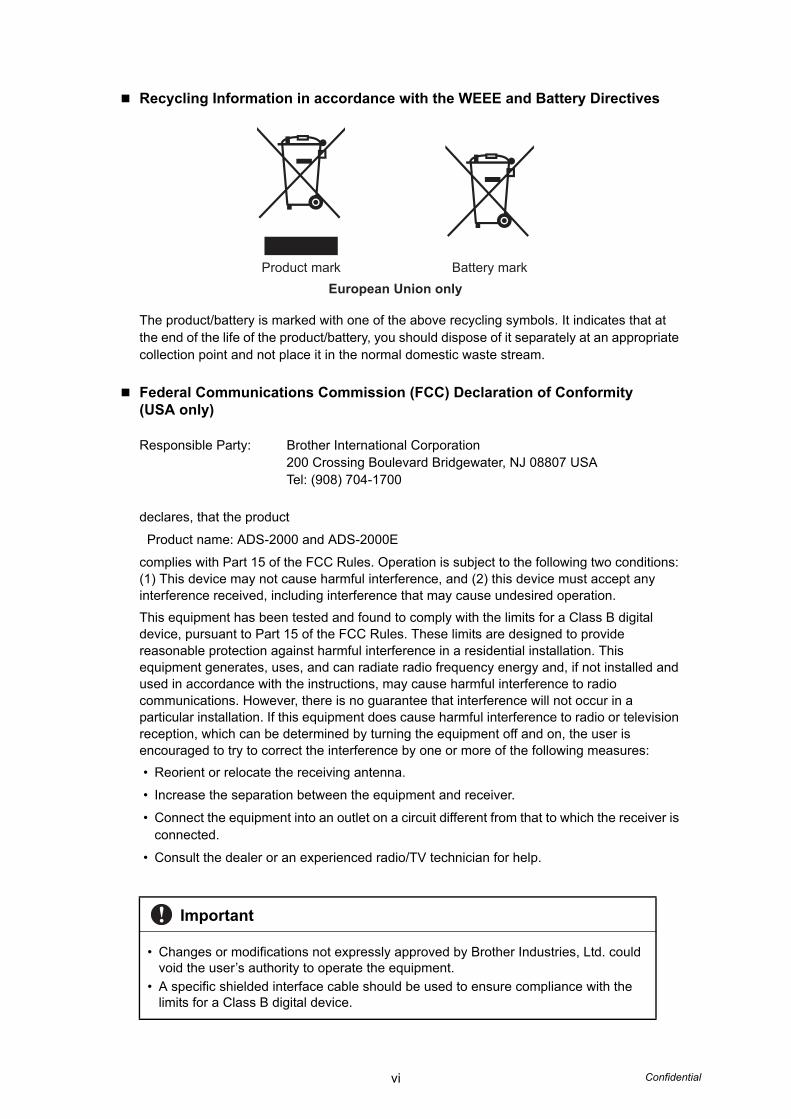
Recycling Information in accordance with the WEEE and Battery Directives
The product/battery is marked with one of the above recycling symbols. It indicates that at the end of the life of the product/battery, you should dispose of it separately at an appropriate collection point and not place it in the normal domestic waste stream.
Federal Communications Commission (FCC) Declaration of Conformity (USA only)
Responsible Party: Brother International Corporation200 Crossing Boulevard Bridgewater, NJ 08807 USATel: (908) 704-1700
declares, that the product
Product name: ADS-2000 and ADS-2000E
complies with Part 15 of the FCC Rules. Operation is subject to the following two conditions: (1) This device may not cause harmful interference, and (2) this device must accept any interference received, including interference that may cause undesired operation.
This equipment has been tested and found to comply with the limits for a Class B digital device, pursuant to Part 15 of the FCC Rules. These limits are designed to provide reasonable protection against harmful interference in a residential installation. This equipment generates, uses, and can radiate radio frequency energy and, if not installed and used in accordance with the instructions, may cause harmful interference to radio communications. However, there is no guarantee that interference will not occur in a particular installation. If this equipment does cause harmful interference to radio or television reception, which can be determined by turning the equipment off and on, the user is encouraged to try to correct the interference by one or more of the following measures:
• Reorient or relocate the receiving antenna.
• Increase the separation between the equipment and receiver.
• Connect the equipment into an outlet on a circuit different from that to which the receiver is connected.
• Consult the dealer or an experienced radio/TV technician for help.
Important
• Changes or modifications not expressly approved by Brother Industries, Ltd. could void the user’s authority to operate the equipment.
• A specific shielded interface cable should be used to ensure compliance with the limits for a Class B digital device.
Product mark Battery markEuropean Union only

vii Confidential
Industry Canada Compliance Statement (Canada only)This Class B digital apparatus complies with Canadian ICES-003.
Cet appareil numérique de la classe B est conforme à la norme NMB-003 du Canada.
Operation is subject to the following two conditions: (1) this device may not cause interference, and (2) this device must accept any interference, including interference that may cause undesired operation of this device.
L’utilisation de ce dispositif est autorisée seulement aux conditions suivantes :(1) il ne doit pas produire de brouillage et (2) l’utilisateur du dispositif doit être prêt à accepter tout brouillage radioélectrique reçu, même si ce brouillage est susceptible de compromettre le fonctionnement du dispositif.
For use in the USA or Canada only
These machines are made for use in the USA and Canada only.
We cannot recommend using them overseas because the power requirements of your machine may not be compatible with the power available in foreign countries. Using USA or Canada models overseas is at your own risk and may void your warranty.
International ENERGY STAR® Qualification Statement
The purpose of the International ENERGY STAR® Program is to promote the development and popularization of energy-efficient office equipment.
As an ENERGY STAR® Partner, Brother Industries, Ltd. has determined that this product meets the ENERGY STAR® specifications for energy efficiency.
viii Confidential
SAFETY INFORMATION
WARNING
WARNING indicates a potentially hazardous situation which, if not avoided, could result in death or serious injuries.
CAUTION
CAUTION indicates a potentially hazardous situation which, if not avoided, may result in minor or moderate injuries.
Important
Important indicates a potentially hazardous situation which, if not avoided, may result in damage to property or loss of product functionality.
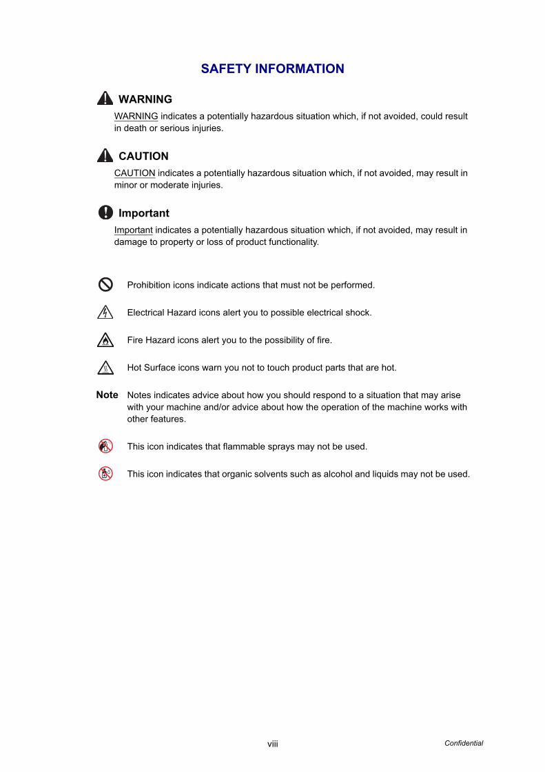
Prohibition icons indicate actions that must not be performed.
Electrical Hazard icons alert you to possible electrical shock.
Fire Hazard icons alert you to the possibility of fire.
Hot Surface icons warn you not to touch product parts that are hot.
Note Notes indicates advice about how you should respond to a situation that may arise with your machine and/or advice about how the operation of the machine works with other features.
This icon indicates that flammable sprays may not be used.
This icon indicates that organic solvents such as alcohol and liquids may not be used.

ix Confidential
To use the Machine SafelyPlease keep these instructions for later reference and read them before attempting any maintenance. If you do not follow these safety instructions, there is a possibility of a fire, electrical shock, burn or suffocation.
WARNING
DO NOT expose the machine to direct sunlight, excessive heat, open flames, corrosive gasses, moisture or dust.DO NOT place your machine on a carpet or rug, as this will expose it to dust. Doing so may create a risk of an electrical short or fire. It may also damage the machine and/or render it inoperable.
DO NOT place the machine near heaters, air conditioners, electric fans, refrigerators, radiators, or water. Doing so may create the risk of a electrical short or fire should water come into contact with the machine (including condensation from heating, air conditioning, and/or ventilation equipment that may be sufficient to create a electrical shock, short circuit or fire).
DO NOT place the machine near chemicals or in a place where chemicals could be spilled on it. Should chemicals come into contact with the machine, there may be a risk of fire or electric shock. In particular, organic solvents or liquids such as benzene, paint thinner, polish remover, or deodorizer may melt or dissolve the plastic cover and/or cables, resulting in a risk of fire or electric shock. These or other chemicals may also cause the machine to malfunction or become discolored.
The product should be placed so as not to come into contact with any wall or other device. Otherwise, it could create a risk of overheating and/or fire. Instead:• Place the machine on a solid surface, never on a bed, sofa, rug, or other similar soft
surface.
• Do not place this machine in a “built-in” installation unless adequate ventilation is provided.
CAUTION
Avoid placing your machine in a high-traffic area. If you must place it in a high-traffic area, ensure that the machine is in a safe location where it cannot be accidentally knocked-over, which could cause injury to you or others and serious damage to the machine.
Ensure that cables and cords leading to the machine are secured so as not to pose a tripping hazard.
DO NOT place this machine on an unstable or tilted cart, stand, table or on any tilted/slanted surface. The machine is heavy and may fall, causing injury to you and serious damage to the machine.

x Confidential
Make sure that no part of the machine protrudes from the desk or stand where the machine is located. In particular, do not leave the output tray open and extended beyond the edge of a cabinet, table or stand when the machine is located on the edge of a cabinet, table, stand, etc. As previously cautioned, make sure that the machine is located on a flat, level, and stable surface free from vibration. Failure to observe these precautions could cause the machine to fall, causing injury to you or others and serious damage to the machine.
Important
• DO NOT place your machine next to sources of interference, such as speakers or the base units of non-Brother cordless telephones. Doing so may interfere with the operation of the machine's electronic components.
• DO NOT connect your machine to an AC power outlet controlled by wall switches or automatic timers. Disruption of power can delete information from the machine's memory, and repeated cycling of the power can damage the machine.
WARNING
ELECTRICAL HAZARDSFailure to follow the warnings in this section may create the risk of an electrical shock. In addition, you could create an electrical short, which may create the risk of a fire.
There are high-voltage electrodes inside the machine. Before you access the inside of the machine, including for routine maintenance such as cleaning, make sure you have unplugged the power cord from the AC power outlet, as well as unplugged any Ethernet (RJ-45) (ADS-2500WE only) cables from the machine.DO NOT push objects of any kind into the machine through slots or openings in the casing, as they may touch dangerous voltage points or short out parts.
DO NOT continue using the machine if it has been dropped or the cabinet has been damaged. Instead, unplug the machine from the power outlet and contact Brother Authorized Service Personnel.

xi Confidential
The machine should be connected to an AC power source within the range indicated on the rating label. DO NOT connect it to a DC power source or inverter. Doing this might cause an electrical shock. If you are not sure what kind of power source you have, contact a qualified electrician.
If water, other liquids, or metal objects get inside the machine, immediately unplug the machine from the AC power outlet and contact Brother Authorized Service Personnel.
Power Cord Safety:• Use only the power cord supplied with this product.
• DO NOT allow anything to rest on the power cord.
• DO NOT place the machine where people can walk on the cord.
• DO NOT place the machine in a position where the cord is stretched or strain is otherwise put on the cord, as it may become worn or frayed.
• DO NOT use the machine or handle the cord if the cord has become worn or frayed. If unplugging the machine, DO NOT touch the damaged/frayed part.
• Brother strongly recommends that you DO NOT use any type of extension cord.
This product was packaged in a plastic bag. To avoid suffocation, keep this plastic bag away from babies and children. Do not use the bag in cribs, beds, carriages or play pens. The bag is not a toy.
FIRE HAZARDSFailure to follow the warnings in this section may create the risk of a fire.
DO NOT use flammable substances, any type of spray or an organic solvent/liquid that contains alcohol or ammonia to clean the inside or outside of the machine. Doing this may cause a risk of fire or electrical shock.
Do not disassemble or modify the machine, otherwise fire or electric shock may result. If the machine requires repair, contact the place of purchase or Brother Authorized Service Personnel.
If the machine becomes hot, releases smoke, or generates any strong or unusual odors, immediately unplug the machine from the power outlet and call Brother Customer Service.
DO NOT handle the plug with wet hands.
xii Confidential
CAUTION
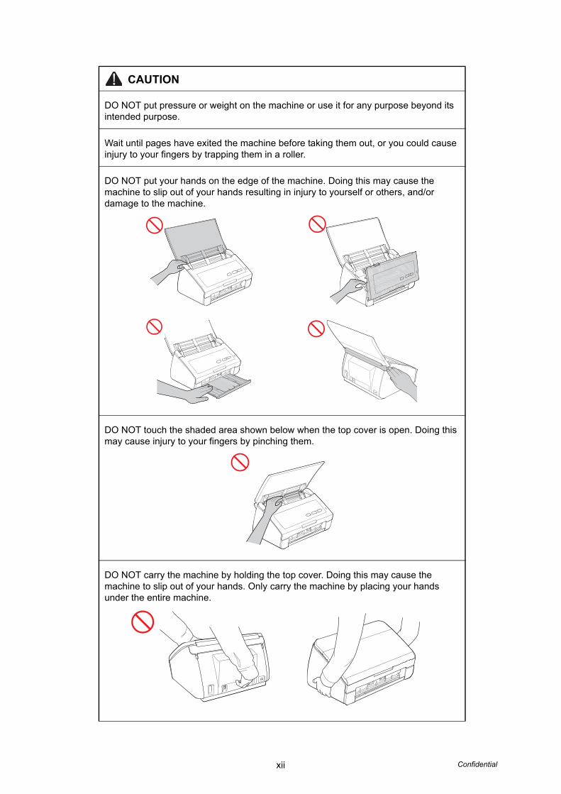
DO NOT put pressure or weight on the machine or use it for any purpose beyond its intended purpose.
Wait until pages have exited the machine before taking them out, or you could cause injury to your fingers by trapping them in a roller.
DO NOT put your hands on the edge of the machine. Doing this may cause the machine to slip out of your hands resulting in injury to yourself or others, and/or damage to the machine.
DO NOT touch the shaded area shown below when the top cover is open. Doing this may cause injury to your fingers by pinching them.
DO NOT carry the machine by holding the top cover. Doing this may cause the machine to slip out of your hands. Only carry the machine by placing your hands under the entire machine.
xiii Confidential
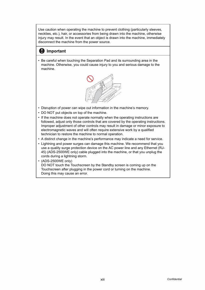
Use caution when operating the machine to prevent clothing (particularly sleeves, neckties, etc.), hair, or accessories from being drawn into the machine, otherwise injury may result. In the event that an object is drawn into the machine, immediately disconnect the machine from the power source.
Important
• Be careful when touching the Separation Pad and its surrounding area in the machine. Otherwise, you could cause injury to you and serious damage to the machine.
• Disruption of power can wipe out information in the machine’s memory.
• DO NOT put objects on top of the machine.
• If the machine does not operate normally when the operating instructions are followed, adjust only those controls that are covered by the operating instructions. Improper adjustment of other controls may result in damage or minor exposure to electromagnetic waves and will often require extensive work by a qualified technician to restore the machine to normal operation.
• A distinct change in the machine’s performance may indicate a need for service.
• Lightning and power surges can damage this machine. We recommend that you use a quality surge protection device on the AC power line and any Ethernet (RJ-45) (ADS-2500WE only) cable plugged into the machine, or that you unplug the cords during a lightning storm.
• (ADS-2500WE only)DO NOT touch the Touchscreen by the Standby screen is coming up on the Touchscreen after plugging in the power cord or turning on the machine. Doing this may cause an error.

Confidential
CHAPTER 1SPECIFICATIONS

Confidential
CHAPTER 1 SPECIFICATIONS
This chapter lists the specifications of each model.
CONTENTS1. SPECIFICATIONS LIST ................................................................................................1-1
1.1 General..................................................................................................................1-1
1.2 Network Connectivity.............................................................................................1-3
1.3 Service Information................................................................................................1-3
1.4 Consumable Parts .................................................................................................1-3
1.5 Paper .....................................................................................................................1-4
1.5.1 Paper handling ...........................................................................................1-4
1.5.2 Media specifications ...................................................................................1-4
1.6 Scanner .................................................................................................................1-4
1-1 Confidential
1. SPECIFICATIONS LIST
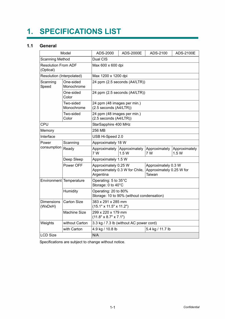
1.1 General
Specifications are subject to change without notice.
Model ADS-2000 ADS-2000E ADS-2100 ADS-2100E
Scanning Method Dual CIS
Resolution From ADF (Optical)
Max 600 x 600 dpi
Resolution (Interpolated) Max 1200 x 1200 dpi
Scanning Speed
One-sidedMonochrome
24 ppm (2.5 seconds (A4/LTR))
One-sidedColor
24 ppm (2.5 seconds (A4/LTR))
Two-sidedMonochrome
24 ppm (48 images per min.)(2.5 seconds (A4/LTR))
Two-sidedColor
24 ppm (48 images per min.)(2.5 seconds (A4/LTR))
CPU StarSapphire 400 MHz
Memory 256 MB
Interface USB Hi-Speed 2.0
Powerconsumption
Scanning Approximately 18 W
Ready Approximately 7 W
Approximately 1.5 W
Approximately 7 W
Approximately 1.5 W
Deep Sleep Approximately 1.5 W
Power OFF Approximately 0.25 WApproximately 0.3 W for Chile, Argentina
Approximately 0.3 WApproximately 0.25 W for Taiwan
Environment Temperature Operating: 5 to 35°CStorage: 0 to 40°C
Humidity Operating: 20 to 80%Storage: 10 to 90% (without condensation)
Dimensions(WxDxH)
Carton Size 383 x 291 x 285 mm(15.1" x 11.5" x 11.2")
Machine Size 299 x 220 x 179 mm (11.8" x 8.7" x 7.1")
Weights without Carton 3.3 kg / 7.3 lb (without AC power cord)
with Carton 4.9 kg / 10.8 lb 5.4 kg / 11.7 lb
LCD Size N/A

1-2 Confidential
<Computer requirements>
Specifications are subject to change without notice.
Computer Platform & Operating System Version
Processor Minimum
Speed
Minimum RAM
Recom-mended
RAM
Hard Disk Spaceto install Supported
PC Interface For
DriversFor
Applications
Windows® OperatingSystem
Windows® XPHome (SP2 or greater) *2
Windows® XPProfessional(SP2 or greater) *2
Intel® Pentium® II or equivalent
128 MB 256 MB 150 MB ADS2000/2100
1.5GB
ADS2000E/2100E
1GB
USB
Windows Vista® *2
Intel® Pentium® 4 or equivalent 64-bit (Intel® 64 or AMD 64) supported CPU
512 MB 1 GB 500 MB
Windows® 7 *2 1 GB (32-bit)
2 GB (64-bit)
1 GB (32-bit)
2 GB (64-bit)
650 MB
Windows® 8
Windows® 8.1
Macintosh Operating System
OS X 10.5.8 PowerPC® G4/G5Intel® Processor
512 MB 1 GB 80 MB ADS2000/2100
580MB
ADS2000E/2100E
1GB
USB *1
OS X 10.6.x Intel® Processor
1 GB 2 GB
OS X 10.7.x 2 GB 2 GB
OS X 10.8.x
OS X 10.9.x
*1 Third party USB ports are not supported.
*2 NuanceTM Paper portTM 12SE supports Windows® XP Home (SP3 or greater), XP Professional (SP3 or greater), Windows Vista® (SP2 or greater) and Windows® 7.
1-3 Confidential
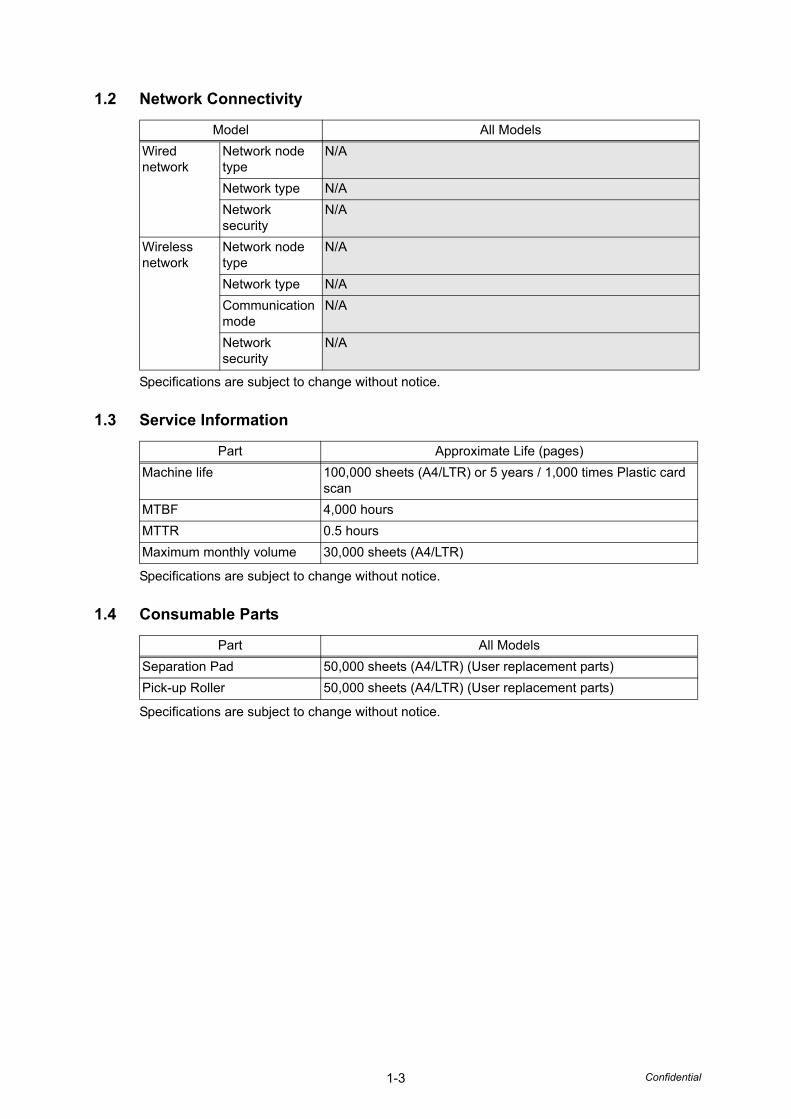
1.2 Network Connectivity
Specifications are subject to change without notice.
1.3 Service Information
Specifications are subject to change without notice.
1.4 Consumable Parts
Specifications are subject to change without notice.
Model All Models
Wired network
Network node type
N/A
Network type N/A
Network security
N/A
Wireless network
Network node type
N/A
Network type N/A
Communication mode
N/A
Network security
N/A
Part Approximate Life (pages)
Machine life 100,000 sheets (A4/LTR) or 5 years / 1,000 times Plastic card scan
MTBF 4,000 hours
MTTR 0.5 hours
Maximum monthly volume 30,000 sheets (A4/LTR)
Part All Models
Separation Pad 50,000 sheets (A4/LTR) (User replacement parts)
Pick-up Roller 50,000 sheets (A4/LTR) (User replacement parts)
1-4 Confidential
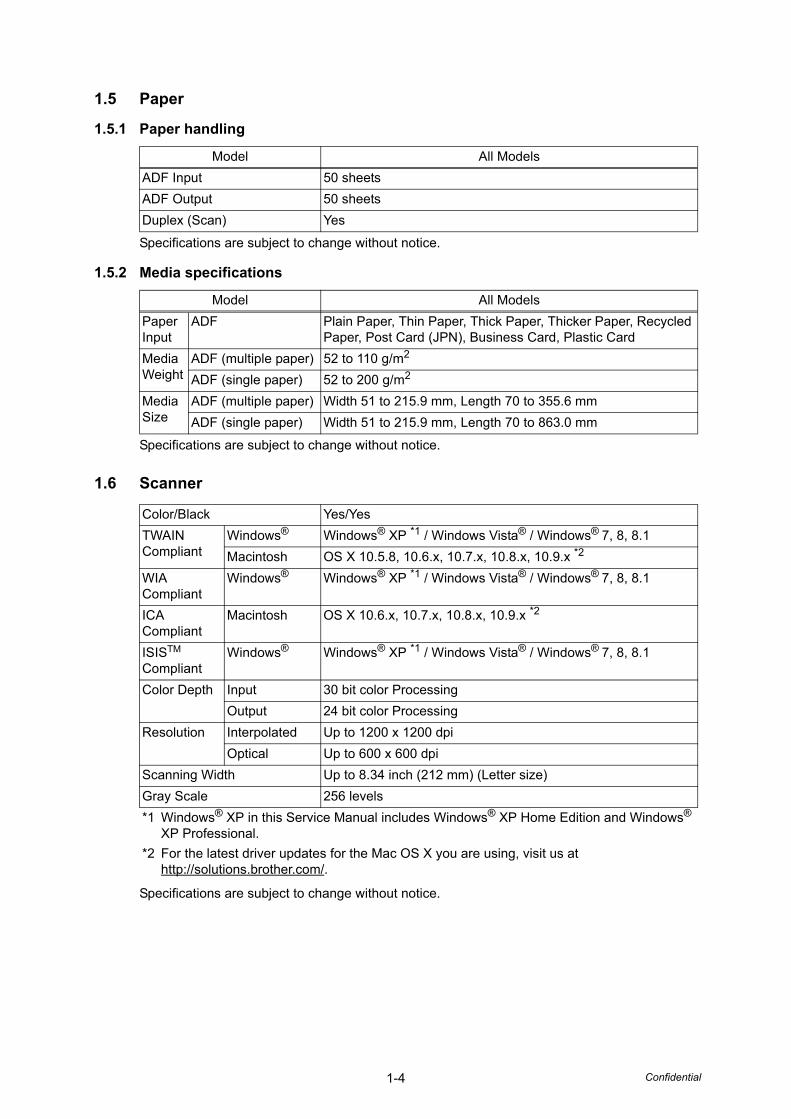
1.5 Paper
1.5.1 Paper handling
Specifications are subject to change without notice.
1.5.2 Media specifications
Specifications are subject to change without notice.
1.6 Scanner
Specifications are subject to change without notice.
Model All Models
ADF Input 50 sheets
ADF Output 50 sheets
Duplex (Scan) Yes
Model All Models
Paper Input
ADF Plain Paper, Thin Paper, Thick Paper, Thicker Paper, Recycled Paper, Post Card (JPN), Business Card, Plastic Card
Media Weight
ADF (multiple paper) 52 to 110 g/m2
ADF (single paper) 52 to 200 g/m2
Media Size
ADF (multiple paper) Width 51 to 215.9 mm, Length 70 to 355.6 mm
ADF (single paper) Width 51 to 215.9 mm, Length 70 to 863.0 mm
Color/Black Yes/Yes
TWAIN Compliant
Windows® Windows® XP *1 / Windows Vista® / Windows® 7, 8, 8.1
Macintosh OS X 10.5.8, 10.6.x, 10.7.x, 10.8.x, 10.9.x *2
WIA Compliant
Windows® Windows® XP *1 / Windows Vista® / Windows® 7, 8, 8.1
ICA Compliant
Macintosh OS X 10.6.x, 10.7.x, 10.8.x, 10.9.x *2
ISISTM Compliant
Windows® Windows® XP *1 / Windows Vista® / Windows® 7, 8, 8.1
Color Depth Input 30 bit color Processing
Output 24 bit color Processing
Resolution Interpolated Up to 1200 x 1200 dpi
Optical Up to 600 x 600 dpi
Scanning Width Up to 8.34 inch (212 mm) (Letter size)
Gray Scale 256 levels
*1 Windows® XP in this Service Manual includes Windows® XP Home Edition and Windows® XP Professional.
*2 For the latest driver updates for the Mac OS X you are using, visit us athttp://solutions.brother.com/.

Confidential
CHAPTER 2TROUBLESHOOTING
Confidential
CHAPTER 2 TROUBLESHOOTING
This chapter details error messages and codes which the incorporated self-diagnostic function of the machine will display if any error or malfunction occurs. If any error message appears, refer to this chapter to find which parts should be checked or replaced.
The latter half of this chapter provides sample problems which could occur in the main sections of the machine and related troubleshooting procedures. These will help service personnel identify and repair other similar defective sections.
CONTENTS1. INTRODUCTION ...........................................................................................................2-1
1.1 Precautions............................................................................................................2-1
1.2 Checks before Commencing Troubleshooting.......................................................2-2
2. OVERVIEW ...................................................................................................................2-3
2.1 Cross-section Drawing ..........................................................................................2-3
2.2 Paper Feeding .......................................................................................................2-4
2.3 Operation of Each Part ..........................................................................................2-5
2.4 Block Diagram .......................................................................................................2-6
2.5 Main Components .................................................................................................2-7
3. ERROR INDICATIONS..................................................................................................2-8
3.1 LED Display when an Error Occurs.......................................................................2-8
3.2 Status Error Messages ........................................................................................2-13
4. TROUBLESHOOTING ................................................................................................2-14
4.1 Troubleshooting for Error Display........................................................................2-14
4.1.1 The double feeding sensor detected multiple documents. .......................2-14
4.1.2 The document scanning position sensor detected that the document length was 40 cm or more. (Document jam)...............2-14
4.1.3 The document scanning position sensor has not detected the top of the document even after the document has been fed for the specified distance. (Document jam) ........................2-14
4.1.4 A non-supported USB device is connected to the USB terminal. A USB device with a built-in hub is connected to the USB terminal. A USB device not within the specifications is connected to the USB terminal, resulting in overcurrent............................................2-15
4.1.5 The scanned data has exceeded the built-in memory capacity................2-15
4.1.6 The first side or second side CIS flat cable is not connected correctly. ...2-15
4.1.7 An error occurred during access to the DRAM in the main PCB ASSY. Program error An error occurred in the ROM checksum. Write error in the EEPROM of the main PCB...........................................2-15
4.1.8 The country code was not entered correctly.............................................2-15
Confidential
4.1.9 The page counter for the separation pad has reached the limit. The page counters for both the separation pad and the pick-up roller have reached the limit. The page counter for the pick-up roller has reached the limit. .................2-16
4.1.10 The front cover sensor detected an open front cover in the ready state. The front cover sensor detected an open front cover during scanning..........2-16
4.1.11 Color parameter in the ROM does not match the first side or second side CIS unit........................................................2-16
4.1.12 A scanning error occurred while scanning the image...............................2-16
4.1.13 The voltage value was below the lower limit during scanning. The white level does not increase during scanning although the light intensity was increased. A white level not within the standard was scanned when the maintenance mode function "Acquire white level data and set CIS scan area" was executed. A black level not within the standard was scanned when the maintenance mode function "Acquire white level data and set CIS scan area" was executed. ............2-17
4.2 Troubleshooting for Image Defects......................................................................2-18
4.2.1 Defect examples.......................................................................................2-18
4.2.2 Troubleshooting according to image defect .............................................2-18
4.3 Troubleshooting for Document Paper Feeding Problems....................................2-22
4.3.1 Multiple documents are fed ......................................................................2-22
4.3.2 Document becomes wrinkled ...................................................................2-22
4.3.3 Document becomes jammed....................................................................2-23
4.3.4 Document is not picked up and fed ..........................................................2-24
4.4 Troubleshooting for Software Problems ..............................................................2-25
4.4.1 Does not respond to operation from a computer......................................2-25
4.4.2 Cannot read data......................................................................................2-25
4.5 Troubleshooting for Control Panel Problems.......................................................2-26
4.5.1 Nothing is displayed on the LED ..............................................................2-26
4.5.2 Control panel is inoperable.......................................................................2-26
4.5.3 Only specified buttons are inoperable ......................................................2-26
4.6 Troubleshooting for Other Problems....................................................................2-27
4.6.1 Machine does not turn ON .......................................................................2-27
4.6.2 Unusual noise is coming from the machine..............................................2-27
4.6.3 Data cannot be saved in the USB memory ..............................................2-27

2-1 Confidential
1. INTRODUCTION
Troubleshooting is a collection of solution procedures that service personnel should follow if an error or malfunction occurs in the machine. It is difficult to determine troubleshooting procedures for all possible problems that may occur in the future. Therefore, this chapter describes typical problem cases and recovery procedures for these. These will help service personnel identify and repair other similar defective sections.
1.1 Precautions
Be sure to observe the following precautions to prevent any secondary problems occurring during troubleshooting:
(1) Be sure to unplug the AC power cord before removing any covers or PCBs, adjusting the machine, or conducting continuity tests using a tester.
(2) Do not hold the cable when connecting or disconnecting the cable. Be sure to hold the connector.
(3) Static electricity generated and stored on your body may damage electronic parts.Before handling the PCBs, touch a metal section of the machine to discharge static electricity.When transporting PCBs, be sure to wrap them in conductive sheets.When replacing PCBs, wear a grounding wrist band and perform replacement on a conductive mat. Also take care not to touch the conductor sections on the flat cables.
(4) Be sure to always observe all warnings.
(5) After repair is completed, check that the repaired sections operate normally.

2-2 Confidential
1.2 Checks before Commencing Troubleshooting
Check the following items before commencing repairs on the machine.
Operating environment(1) The machine is placed on a flat, stable surface.
(2) The machine is used in a clean environment where the temperature is between 5°C (41°F) and 35°C (95°F) and the relative humidity is maintained between 20% and 80%.
(3) The machine is not exposed to direct sunlight, excessive heat, moisture, or dust.
(4) Hold the machine level while moving it.
Power supply
(1) Power described on the rating label attached on the machine is supplied. Power fluctuation should be within ±10% of the rated voltage.
(2) The AC input power supply is within the regulated value.
(3) The cables and harnesses are connected correctly.
(4) The fuses are not blown.
Document
(1) The recommended paper is used for the document. (Refer to "1.5.2 Media specifications" in Chapter 1.)
(2) The document is not damp.
(3) Acid paper is not used.
Others
(1) Condensation
When the machine is moved to a warm room from a cold location, condensation may occur inside the machine, causing various problems as listed below.
• Condensation on the surface of optical devices such as the CIS glass and CIS unit may result in poor quality of scanned images.
• Condensation on the pick-up roller or separation pad may cause document feed problems.If condensation has formed in the machine, leave the machine for at least two hours until it reaches room temperature.
(2) Low temperature
The motor may not operate normally in a cold environment because too much load is applied to each drive. In this case, increase the room temperature.
Cleaning
Use a soft lint-free cloth.
WARNING
DO NOT use any flammable spray or flammable solvent such as alcohol, benzine, or thinner to clean the machine. DO NOT use these articles near the machine.
2-3 Confidential
2. OVERVIEW
2.1 Cross-section Drawing
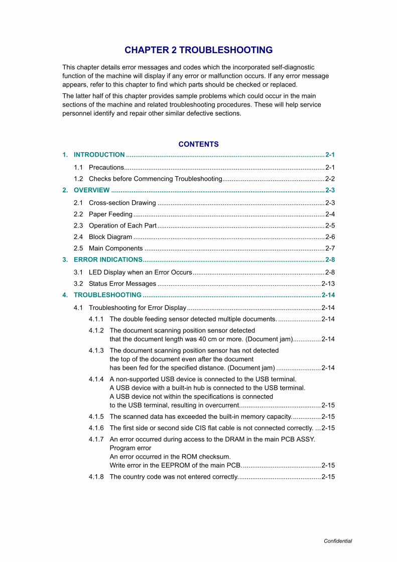
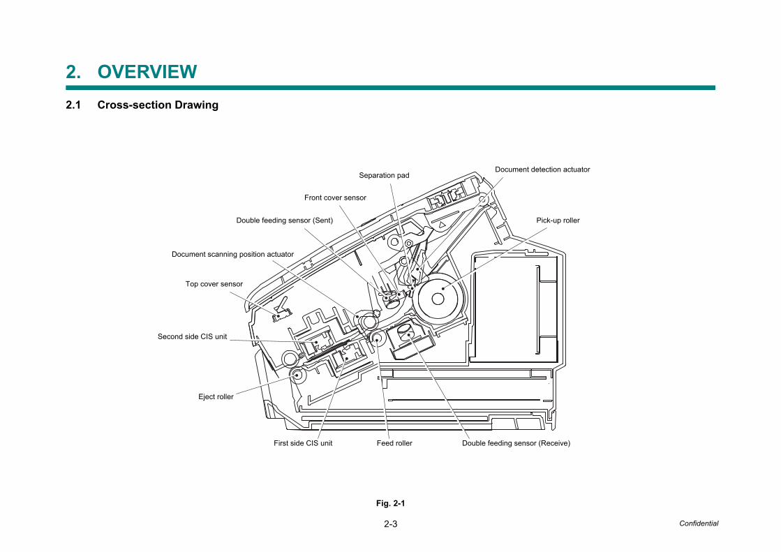
Fig. 2-1
Separation padDocument detection actuator
Front cover sensor
Double feeding sensor (Sent)
Document scanning position actuator
Top cover sensor
Second side CIS unit
Eject roller
First side CIS unit
Pick-up roller
Double feeding sensor (Receive)Feed roller
2-4 Confidential
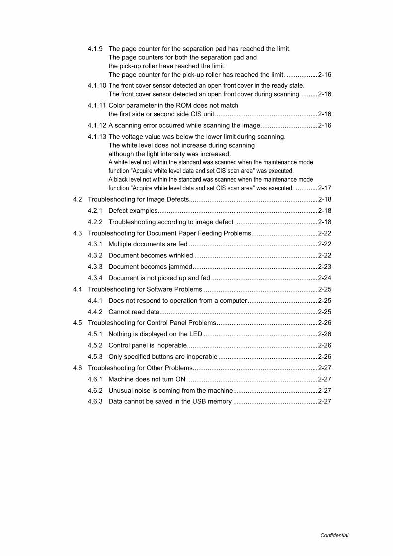
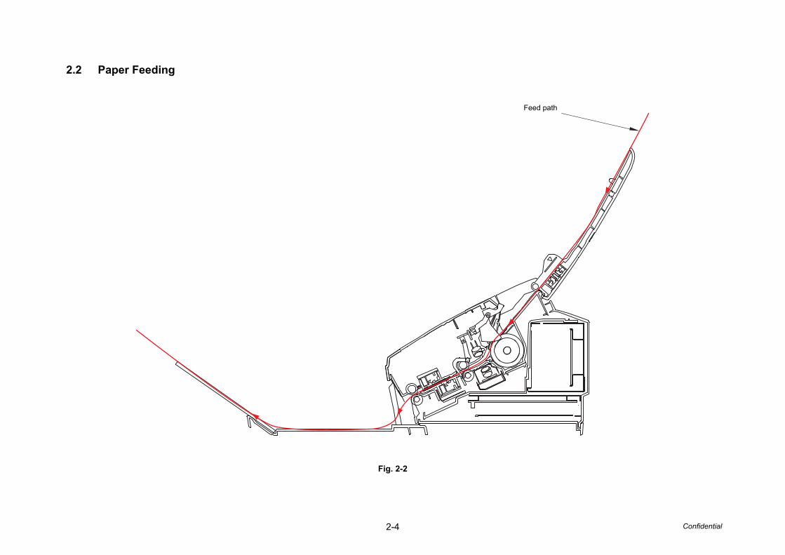
2.2 Paper Feeding
Fig. 2-2
Feed path

2-5 Confidential
2.3 Operation of Each Part
Part name Operation
Pick-up roller / Separation pad
Separates documents set in the document tray into single sheets, and feeds them into the machine.
Double feeding sensor Detects whether multiple documents are fed into the machine.
Feed roller Feeds the document.
Eject roller Feeds the document to the output tray.
Document detection sensor Detects the document set in the document tray. Detects document jams.
Document scanning position sensor
Detects the document scanning start position. Detects document jams.
Front cover sensor Detects whether the front cover is open or closed.
Top cover sensor Detects whether the top cover is open or closed.

2-6 Confidential
2.4 Block Diagram
Fig. 2-3
Inlet
POWER LED
ERROR LED
Scan to USB LED
Scan to PC LED
Panel PCB
Top cover sensor
Document detection sensor
Document scanning position sensor
First side CIS unit
Second side CIS unit
Main PCB
USB
USB host PCB
Front cover sensor
Double feeding sensor (Receive)
Main motor
Power supply PCB
Double feeding sensor (Sent)
2-7 Confidential
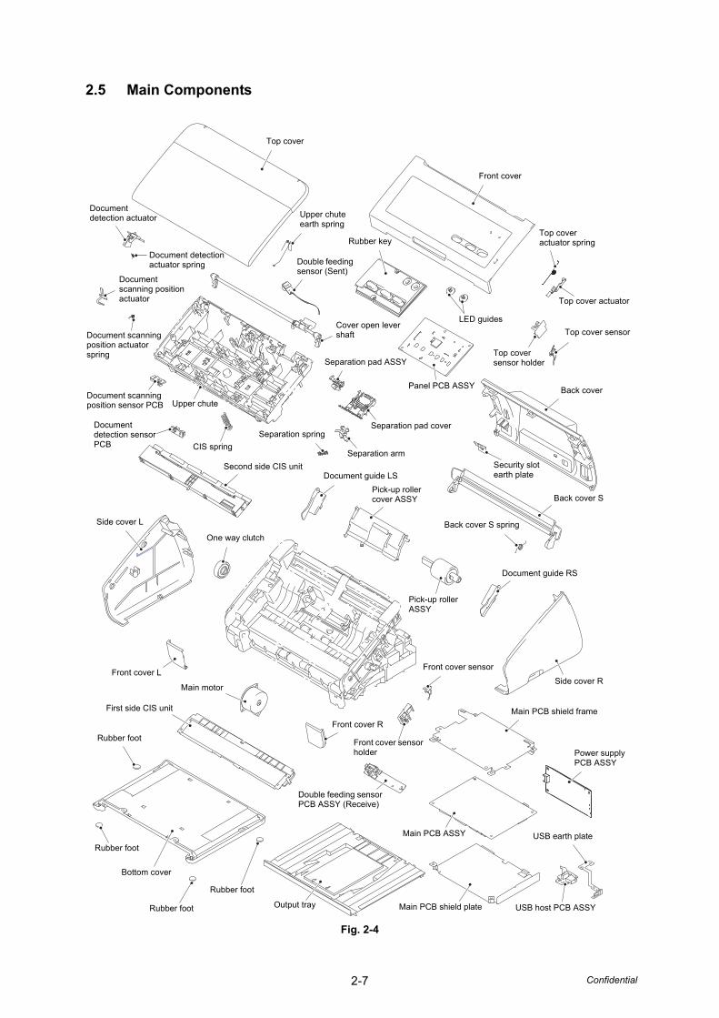
2.5 Main Components
Fig. 2-4
Top cover actuator spring
Front cover
Top cover actuator
Top cover sensor
LED guides
Document detection actuator
Rubber key
Top cover sensor holder
Panel PCB ASSY Back cover
Back cover S
Security slot earth plate
Back cover S spring
Side cover R
Document guide RS
Pick-up roller ASSY
Pick-up roller cover ASSY
Document guide LS
Main PCB shield frame
Power supply PCB ASSY
Front cover sensor
Front cover sensor holder
Double feeding sensor PCB ASSY (Receive)
Main PCB ASSY
Front cover R
First side CIS unit
USB earth plate
USB host PCB ASSYMain PCB shield plateOutput trayRubber foot
Bottom cover
Rubber foot
Main motor
Front cover L
Side cover L
Document detection sensor PCB
Document scanning position sensor PCB
Separation spring
CIS spring
Second side CIS unit
Separation arm
Separation pad cover
Upper chute
Rubber foot
One way clutch
Separation pad ASSY
Cover open lever shaft
Double feeding sensor (Sent)
Upper chute earth spring
Top cover
Document detection actuator spring
Document scanning position actuator spring
Document scanning position actuator
Rubber foot

2-8 Confidential
3. ERROR INDICATIONS
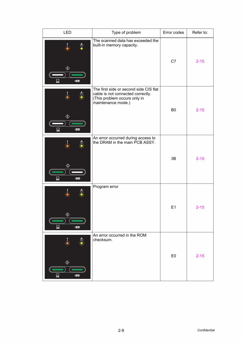
3.1 LED Display when an Error Occurs
Determine the message details according to the LED display on the control panel. Refer to the page shown in the "Refer to:" column in the table below to take appropriate measures.
Most errors are automatically cleared after measures are taken. If not automatically cleared, press the [Stop] button. If the error is still not cleared, unplug the AC power cord to reset the machine.
LED status in the table below: Unlit Lit Flashing
LED Type of problem Error codes Refer to:
The double feeding sensor detected multiple documents.
AB 2-14
The document scanning position sensor detected that the document length was 40 cm or more.
A2 2-14
The document scanning position sensor has not detected the top of the document even after the document has been fed for the specified distance.
A3 2-14
A non-supported USB device is connected to the USB terminal.
- 2-15
A USB device with a built-in hub is connected to the USB terminal.
- 2-15
2-9 Confidential
The scanned data has exceeded the built-in memory capacity.
C7 2-15
The first side or second side CIS flat cable is not connected correctly. (This problem occurs only in maintenance mode.)
B0 2-15
An error occurred during access to the DRAM in the main PCB ASSY.
3B 2-15
Program error
E1 2-15
An error occurred in the ROM checksum.
E0 2-15
LED Type of problem Error codes Refer to:
2-10 Confidential
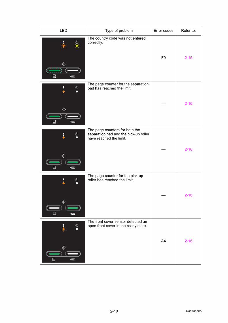
The country code was not entered correctly.
F9 2-15
The page counter for the separation pad has reached the limit.
- 2-16
The page counters for both the separation pad and the pick-up roller have reached the limit.
- 2-16
The page counter for the pick-up roller has reached the limit.
- 2-16
The front cover sensor detected an open front cover in the ready state.
A4 2-16
LED Type of problem Error codes Refer to:
2-11 Confidential
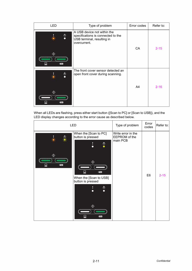
When all LEDs are flashing, press either start button ([Scan to PC] or [Scan to USB]), and the LED display changes according to the error cause as described below.
A USB device not within the specifications is connected to the USB terminal, resulting in overcurrent.
CA 2-15
The front cover sensor detected an open front cover during scanning.
A4 2-16
LED Type of problem Error codes Refer to:
When the [Scan to PC] button is pressed
When the [Scan to USB] button is pressed
Write error in the EEPROM of the main PCB
E6 2-15
LED Type of problem Error codes Refer to:

2-12 Confidential
When the [Scan to PC] button is pressed
When the [Scan to USB] button is pressed
Color parameter in the ROM does not match the first side or second side CIS unit.
A7 2-16
When the [Scan to PC] button is pressed
When the [Scan to USB] button is pressed
A scanning error occurred while scanning the image.
A9 2-16
LED Type of problem Error codes Refer to:
2-13 Confidential
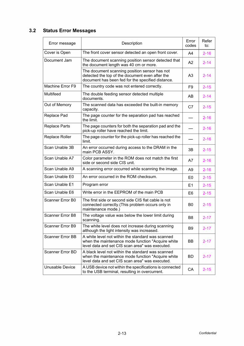
3.2 Status Error Messages
Error message Description Error codes
Refer to:
Cover is Open The front cover sensor detected an open front cover. A4 2-16
Document Jam The document scanning position sensor detected that the document length was 40 cm or more. A2 2-14
The document scanning position sensor has not detected the top of the document even after the document has been fed for the specified distance.
A3 2-14
Machine Error F9 The country code was not entered correctly. F9 2-15
Multifeed The double feeding sensor detected multiple documents. AB 2-14
Out of Memory The scanned data has exceeded the built-in memory capacity. C7 2-15
Replace Pad The page counter for the separation pad has reached the limit. - 2-16
Replace Parts The page counters for both the separation pad and the pick-up roller have reached the limit. - 2-16
Replace Roller The page counter for the pick-up roller has reached the limit. - 2-16
Scan Unable 3B An error occurred during access to the DRAM in the main PCB ASSY. 3B 2-15
Scan Unable A7 Color parameter in the ROM does not match the first side or second side CIS unit. A7 2-16
Scan Unable A9 A scanning error occurred while scanning the image. A9 2-16
Scan Unable E0 An error occurred in the ROM checksum. E0 2-15
Scan Unable E1 Program error E1 2-15
Scan Unable E6 Write error in the EEPROM of the main PCB E6 2-15
Scanner Error B0 The first side or second side CIS flat cable is not connected correctly.(This problem occurs only in maintenance mode.)
B0 2-15
Scanner Error B8 The voltage value was below the lower limit during scanning. B8 2-17
Scanner Error B9 The white level does not increase during scanning although the light intensity was increased. B9 2-17
Scanner Error BB A white level not within the standard was scanned when the maintenance mode function "Acquire white level data and set CIS scan area" was executed.
BB 2-17
Scanner Error BD A black level not within the standard was scanned when the maintenance mode function "Acquire white level data and set CIS scan area" was executed.
BD 2-17
Unusable Device A USB device not within the specifications is connected to the USB terminal, resulting in overcurrent. CA 2-15

2-14 Confidential
4. TROUBLESHOOTING
4.1 Troubleshooting for Error Display
4.1.1 The double feeding sensor detected multiple documents.
4.1.2 The document scanning position sensor detected that the document lengthwas 40 cm or more. (Document jam)
4.1.3 The document scanning position sensor has not detected the top of thedocument even after the document has been fed for the specified distance.(Document jam)
<User Check>
- Check that the paper used for the document is within the standard.
Step Cause Remedy
1Incorrect double feeding sensor threshold setting
Reset the double feeding sensor threshold.
2 Double feeding sensor failure Replace the double feeding sensor.
3 Panel PCB failure Replace the panel PCB ASSY.
4 Main PCB failure Replace the main PCB ASSY.
<User Check>
- Check that the document guide is adjusted to suit the document size.
Step Cause Remedy
1Document scanning position actuator caught in sections of the machine
Reattach the document scanning position actuator.
2 Main PCB failure Replace the main PCB ASSY.
<User Check>
- Check that the document size is within the standard.
- Check that the document is not wrinkled.
- Check that the document is not torn.
- Check that the front cover is closed correctly.
Step Cause Remedy
1Document scanning position actuator caught in sections of the machine
Reattach the document scanning position actuator.
2Attachment failure of the gears in the feeding system
Reattach the gears in the feeding system.
3 Separation pad failure Replace the separation pad ASSY.
4Abrasion of the pick-up roller ASSY
Replace the pick-up roller ASSY.
5Misalignment or bending of the pick-up roller support film
Replace the pick-up roller cover ASSY.
6 Front cover sensor failure Replace the front cover sensor.
7 One way clutch failure Replace the one way clutch.
8 Main motor failure Replace the main motor.
9 Main PCB failure Replace the main PCB ASSY.

2-15 Confidential
4.1.4 A non-supported USB device is connected to the USB terminal.A USB device with a built-in hub is connected to the USB terminal.A USB device not within the specifications is connected to the USB terminal,resulting in overcurrent.
4.1.5 The scanned data has exceeded the built-in memory capacity.
4.1.6 The first side or second side CIS flat cable is not connected correctly.
4.1.7 An error occurred during access to the DRAM in the main PCB ASSY.Program errorAn error occurred in the ROM checksum.Write error in the EEPROM of the main PCB.
4.1.8 The country code was not entered correctly.
<User Check>
- Disconnect the USB device.
Step Cause Remedy
1 Main PCB failure Replace the main PCB ASSY.
<User Check>
- Perform scanning by dividing the document.
Step Cause Remedy
1 Main PCB failure Replace the main PCB ASSY.
Step Cause Remedy
1Connection failure of the first side or second side CIS flat cable
Reconnect the first side or second side CIS flat cable.
2First side or second side CIS unit failure
Replace the first side or second side CIS unit.
3 Main PCB failure Replace the main PCB ASSY.
<User Check>
- Unplug the AC power cord and then plug the AC power cord into the outlet.
Step Cause Remedy
1 Main PCB failure Replace the main PCB ASSY.
Step Cause Remedy
1 Incorrect country code Enter the correct country code.
2 Main PCB failure Replace the main PCB ASSY.
2-16 Confidential
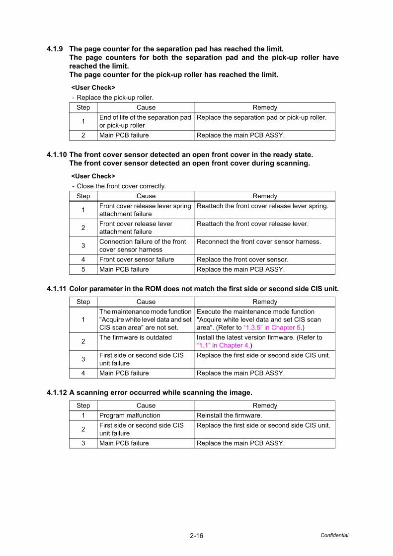
4.1.9 The page counter for the separation pad has reached the limit.The page counters for both the separation pad and the pick-up roller havereached the limit.The page counter for the pick-up roller has reached the limit.
4.1.10 The front cover sensor detected an open front cover in the ready state.The front cover sensor detected an open front cover during scanning.
4.1.11 Color parameter in the ROM does not match the first side or second side CIS unit.
4.1.12 A scanning error occurred while scanning the image.
<User Check>
- Replace the pick-up roller.
Step Cause Remedy
1End of life of the separation pad or pick-up roller
Replace the separation pad or pick-up roller.
2 Main PCB failure Replace the main PCB ASSY.
<User Check>
- Close the front cover correctly.
Step Cause Remedy
1Front cover release lever spring attachment failure
Reattach the front cover release lever spring.
2Front cover release lever attachment failure
Reattach the front cover release lever.
3Connection failure of the front cover sensor harness
Reconnect the front cover sensor harness.
4 Front cover sensor failure Replace the front cover sensor.
5 Main PCB failure Replace the main PCB ASSY.
Step Cause Remedy
1The maintenance mode function "Acquire white level data and set CIS scan area" are not set.
Execute the maintenance mode function "Acquire white level data and set CIS scan area". (Refer to “1.3.5” in Chapter 5.)
2The firmware is outdated Install the latest version firmware. (Refer to
“1.1” in Chapter 4.)
3First side or second side CIS unit failure
Replace the first side or second side CIS unit.
4 Main PCB failure Replace the main PCB ASSY.
Step Cause Remedy
1 Program malfunction Reinstall the firmware.
2First side or second side CIS unit failure
Replace the first side or second side CIS unit.
3 Main PCB failure Replace the main PCB ASSY.

2-17 Confidential
4.1.13 The voltage value was below the lower limit during scanning.The white level does not increase during scanning although the light intensity was increased.A white level not within the standard was scanned when the maintenance mode function"Acquire white level data and set CIS scan area" was executed.A black level not within the standard was scanned when the maintenance mode function"Acquire white level data and set CIS scan area" was executed.
Step Cause Remedy
1 Dirty calibration sheet Replace the calibration sheet with a new one.
2First side or second side CIS unit failure
Replace the first side or second side CIS unit.
3 Main PCB failure Replace the main PCB ASSY.
2-18 Confidential
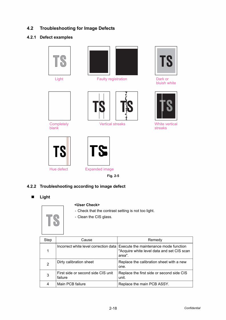
4.2 Troubleshooting for Image Defects
4.2.1 Defect examples
Fig. 2-5
4.2.2 Troubleshooting according to image defect
Light
<User Check>
- Check that the contrast setting is not too light.
- Clean the CIS glass.
Step Cause Remedy
1Incorrect white level correction data Execute the maintenance mode function
"Acquire white level data and set CIS scan area".
2Dirty calibration sheet Replace the calibration sheet with a new
one.
3First side or second side CIS unit failure
Replace the first side or second side CIS unit.
4 Main PCB failure Replace the main PCB ASSY.
Light
White verticalstreaks
Vertical streaks Completelyblank
Hue defect
Faulty registration Dark orbluish white
Expanded image
2-19 Confidential
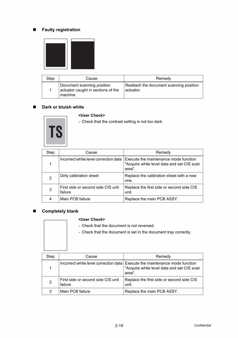
Faulty registration
Dark or bluish white
Completely blank
Step Cause Remedy
1Document scanning position actuator caught in sections of the machine
Reattach the document scanning position actuator.
<User Check>
- Check that the contrast setting is not too dark.
Step Cause Remedy
1Incorrect white level correction data Execute the maintenance mode function
"Acquire white level data and set CIS scan area".
2Dirty calibration sheet Replace the calibration sheet with a new
one.
3First side or second side CIS unit failure
Replace the first side or second side CIS unit.
4 Main PCB failure Replace the main PCB ASSY.
<User Check>
- Check that the document is not reversed.
- Check that the document is set in the document tray correctly.
Step Cause Remedy
1Incorrect white level correction data Execute the maintenance mode function
"Acquire white level data and set CIS scan area".
2First side or second side CIS unit failure
Replace the first side or second side CIS unit.
3 Main PCB failure Replace the main PCB ASSY.
2-20 Confidential
Vertical streaks
White vertical streaks
Hue defect
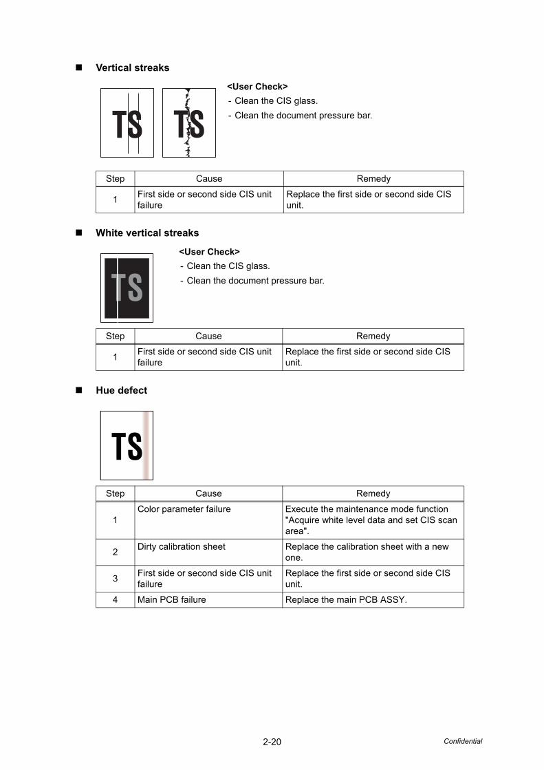
<User Check>
- Clean the CIS glass.
- Clean the document pressure bar.
Step Cause Remedy
1First side or second side CIS unit failure
Replace the first side or second side CIS unit.
<User Check>
- Clean the CIS glass.
- Clean the document pressure bar.
Step Cause Remedy
1First side or second side CIS unit failure
Replace the first side or second side CIS unit.
Step Cause Remedy
1Color parameter failure Execute the maintenance mode function
"Acquire white level data and set CIS scan area".
2Dirty calibration sheet Replace the calibration sheet with a new
one.
3First side or second side CIS unit failure
Replace the first side or second side CIS unit.
4 Main PCB failure Replace the main PCB ASSY.
2-21 Confidential
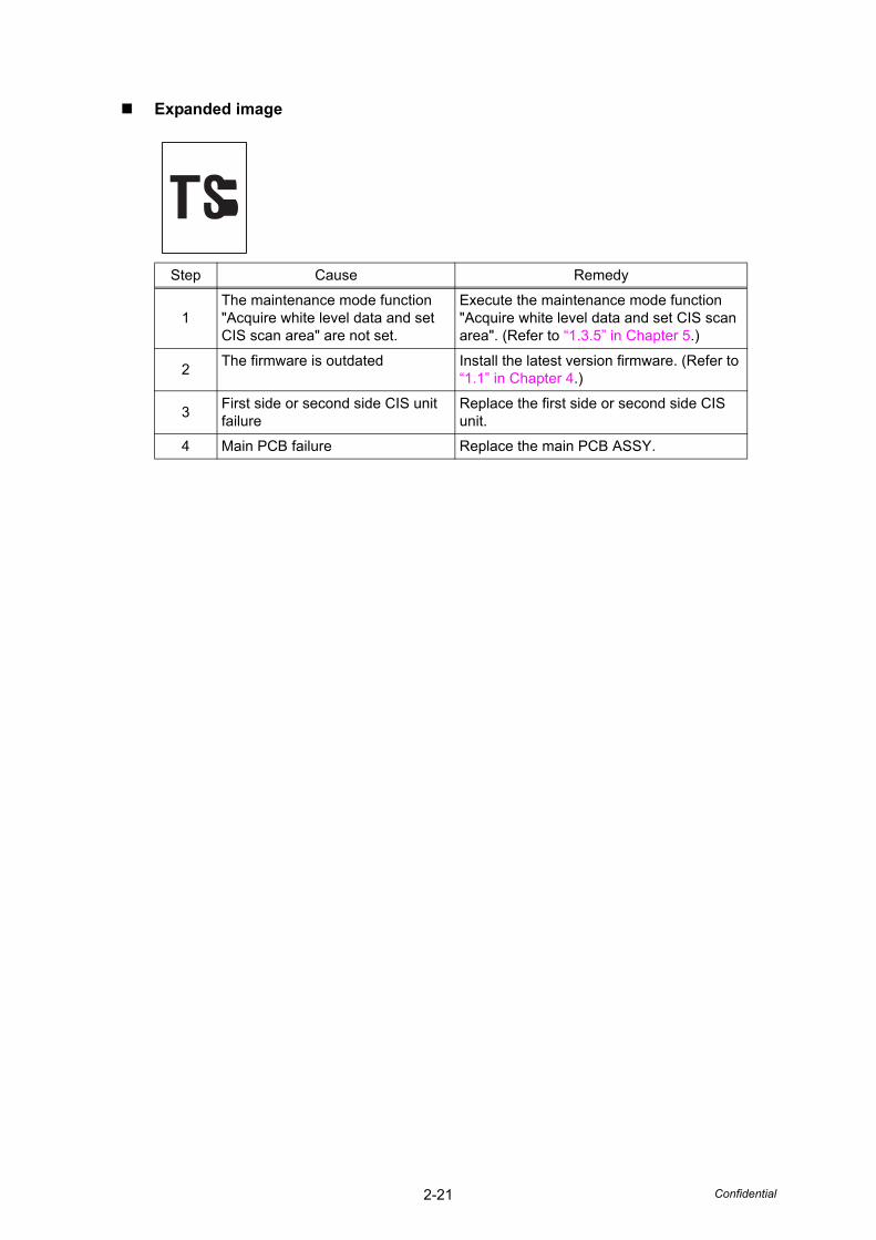
Expanded image
Step Cause Remedy
1The maintenance mode function "Acquire white level data and set CIS scan area" are not set.
Execute the maintenance mode function "Acquire white level data and set CIS scan area". (Refer to “1.3.5” in Chapter 5.)
2The firmware is outdated Install the latest version firmware. (Refer to
“1.1” in Chapter 4.)
3First side or second side CIS unit failure
Replace the first side or second side CIS unit.
4 Main PCB failure Replace the main PCB ASSY.

2-22 Confidential
4.3 Troubleshooting for Document Paper Feeding Problems
4.3.1 Multiple documents are fed
4.3.2 Document becomes wrinkled
<User Check>
- Check that paper used for the document is not thinner than the standard. If it is too thin, use a carrier sheet.
- Check that the document is not damp. If it is damp, dry it or use a carrier sheet.
- Check that the machine is not scanning a glossy paper used in magazines and others.
Step Cause Remedy
1Incorrect double feeding sensor threshold setting
Reset the double feeding sensor threshold.
2Connection failure of the double feeding sensor harness
Reconnect the double feeding sensor harness.
3 Separation spring coming off Reattach the separation spring.
4 Separation arm coming off Reattach the separation arm.
5 Abrasion of the separation pad Replace the separation pad.
6 Abrasion of the pick-up roller Replace the pick-up roller ASSY.
7 Deformed front plate spring Replace the separation pad cover.
8 Bent or broken separation spring Replace the separation spring.
9 Separation arm failure Replace the separation arm.
10 Double feeding sensor failure Replace the double feeding sensor.
<User Check>
- Check that the document guide is adjusted to suit the document size.
- Check that the document is not curled.
Step Cause Remedy
1 Abrasion of the pick-up roller Replace the pick-up roller ASSY.
2-23 Confidential
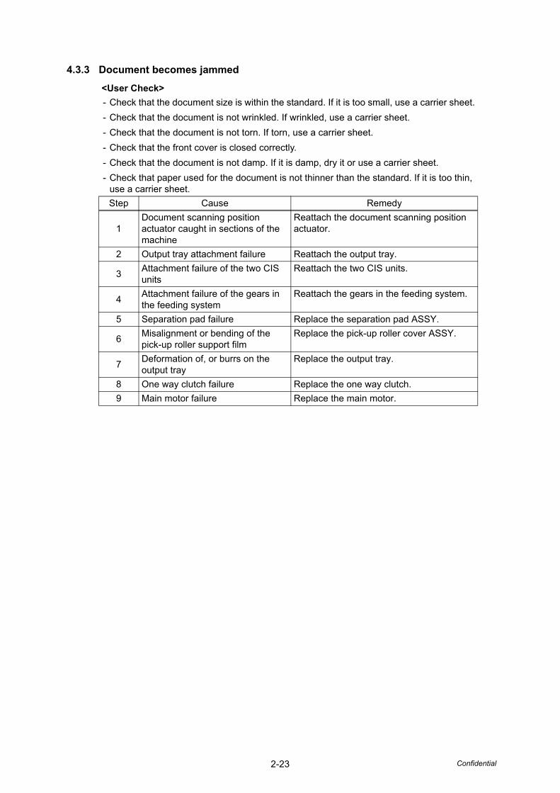
4.3.3 Document becomes jammed
<User Check>
- Check that the document size is within the standard. If it is too small, use a carrier sheet.
- Check that the document is not wrinkled. If wrinkled, use a carrier sheet.
- Check that the document is not torn. If torn, use a carrier sheet.
- Check that the front cover is closed correctly.
- Check that the document is not damp. If it is damp, dry it or use a carrier sheet.
- Check that paper used for the document is not thinner than the standard. If it is too thin, use a carrier sheet.
Step Cause Remedy
1Document scanning position actuator caught in sections of the machine
Reattach the document scanning position actuator.
2 Output tray attachment failure Reattach the output tray.
3Attachment failure of the two CIS units
Reattach the two CIS units.
4Attachment failure of the gears in the feeding system
Reattach the gears in the feeding system.
5 Separation pad failure Replace the separation pad ASSY.
6Misalignment or bending of the pick-up roller support film
Replace the pick-up roller cover ASSY.
7Deformation of, or burrs on the output tray
Replace the output tray.
8 One way clutch failure Replace the one way clutch.
9 Main motor failure Replace the main motor.

2-24 Confidential
4.3.4 Document is not picked up and fed
<User Check>
- Check that paper used for the document is not thinner than the standard. If it is too thin, use a carrier sheet.
- Check that the front cover is closed correctly.
- Check that the separation pad cover is closed correctly.
Step Cause Remedy
1Document detection actuator coming off
Reattach the document detection actuator.
2Connection failure of the document detection sensor harness
Reconnect the document detection sensor harness.
3Connection failure of the top cover sensor harness
Reconnect the top cover sensor harness.
4Connection failure of the front cover sensor harness
Reconnect the front cover sensor harness.
5Connection failure of the main motor harness
Reconnect the main motor harness.
6Attachment failure of the gears in the feeding system
Reattach the gears in the feeding system.
7 Top cover sensor failure Replace the top cover sensor.
8 Front cover sensor failure Replace the front cover sensor.
9Document detection sensor failure Replace the document detection sensor
PCB.
10 One way clutch failure Replace the one way clutch.
11 Deformed front plate spring Replace the separation pad cover.
12 Main motor failure Replace the main motor.
13 Main PCB failure Replace the main PCB ASSY.

2-25 Confidential
4.4 Troubleshooting for Software Problems
End users can solve problems related to software, for instance, scanning is not possible from a computer although scanning can be performed from the machine, as long as they follow the User Check items. If the problem still cannot be solved, follow each procedure according to the step number in the tables below.
4.4.1 Does not respond to operation from a computer
4.4.2 Cannot read data
<User Check>
- Check that the USB cable is not damaged.
- When using an interface switch, check that the correct machine is selected.
- Check the relevant section in the User's Guide.
- Check the driver settings.
- Reset the machine to the default settings. (Refer to the User's Guide.)
- Unplug the AC power cord and then plug the AC power cord again into the outlet.
Step Cause Remedy
1 Program malfunction Reinstall the firmware.
2Connection failure of the front cover sensor harness
Reconnect the front cover sensor harness.
3Connection failure of the top cover sensor harness
Reconnect the top cover sensor harness.
4 Rubber key attachment failure Reattach the rubber key.
5 Front cover sensor failure Replace the front cover sensor ASSY.
6 Top cover sensor failure Replace the top cover sensor ASSY.
7 Main PCB failure Replace the main PCB ASSY.
<User Check>
- Check the relevant section in the User's Guide.
- Unplug the AC power cord and then plug the AC power cord again into the outlet.
Step Cause Remedy
1Connection failure of the front cover sensor harness
Reconnect the front cover sensor harness.
2Connection failure of the top cover sensor harness
Reconnect the top cover sensor harness.
3 Front cover sensor failure Replace the front cover sensor ASSY.
4 Top cover sensor failure Replace the top cover sensor ASSY.
5First side or second side CIS unit failure
Replace the first side or second side CIS unit.
6 Main PCB failure Replace the main PCB ASSY.

2-26 Confidential
4.5 Troubleshooting for Control Panel Problems
4.5.1 Nothing is displayed on the LED
4.5.2 Control panel is inoperable
4.5.3 Only specified buttons are inoperable
<User Check>
- Check that the AC power cord is connected correctly.
Step Cause Remedy
1 AC power cord failure Replace the AC power cord.
2Connection failure of the panel PCB harness
Reconnect the panel PCB harness.
3Connection failure of the top cover sensor harness
Reconnect the top cover sensor harness.
4 Top cover sensor failure Replace the top cover sensor ASSY.
5 Panel PCB failure Replace the panel PCB ASSY.
6 Power supply PCB failure Replace the power supply PCB ASSY.
7 Main PCB failure Replace the main PCB ASSY.
<User Check>
- Check that the function lock is not set.
Step Cause Remedy
1 Panel ASSY attachment failure Reattach the panel ASSY.
2Connection failure of the panel PCB harness
Reconnect the panel PCB harness.
3Connection failure of the front cover sensor harness
Reconnect the front cover sensor harness.
4 Front cover sensor failure Replace the front cover sensor ASSY.
5 Rubber key failure Replace the rubber key.
6 Panel PCB failure Replace the panel PCB ASSY.
7 Power supply PCB failure Replace the power supply PCB ASSY.
8 Main PCB failure Replace the main PCB ASSY.
Step Cause Remedy
1 Panel ASSY attachment failure Reattach the panel ASSY.
2 Rubber key failure Replace the rubber key.
3 Panel PCB failure Replace the panel PCB ASSY.

2-27 Confidential
4.6 Troubleshooting for Other Problems
4.6.1 Machine does not turn ON
4.6.2 Unusual noise is coming from the machine
4.6.3 Data cannot be saved in the USB memory
<User Check>
- Connect the AC power cord correctly.
Step Cause Remedy
1Connection failure of the panel PCB harness
Reconnect the panel PCB harness.
2Connection failure of the top cover sensor harness
Reconnect the top cover sensor harness.
3 Top cover sensor failure Replace the top cover sensor ASSY.
4 Panel PCB failure Replace the panel PCB ASSY.
5 Power supply PCB failure Replace the power supply PCB ASSY.
6 Main PCB failure Replace the main PCB ASSY.
<User Check>
- Check that the front cover is closed correctly.
Step Cause Remedy
1Possible cause differs depending on the location. Identify the location with the problem.
When the location with the problem is identified, check if there is a foreign object around that location.
2 Bent or defective part Replace the part.
<User Check>
- Check that the USB memory is inserted into the USB terminal correctly.
- Replace the USB memory and try saving data again.
Step Cause Remedy
1 Rubber key attachment failure Reattach the rubber key.
2 Rubber key failure Replace the rubber key.
3 Panel PCB failure Replace the panel PCB ASSY.
4 Main PCB failure Replace the main PCB ASSY.

Confidential
CHAPTER 3DISASSEMBLY/REASSEMBLY
Confidential
CHAPTER 3 DISASSEMBLY/REASSEMBLY
This chapter describes procedures for disassembling and reassembling the machine with related notes. The provided disassembly order flow enables you to take in the disassembly procedure of related part at a glance.
At the start of disassembling, you can check the disassembly order flow which guides you through a shortcut to get to the part.
This chapter also covers screw tightening torques and lubrication points where the specified lubrication should be applied when the machine is assembled.
CONTENTS
1. SAFETY PRECAUTIONS .............................................................................................3-1
2. PACKING ......................................................................................................................3-2
3. SCREW CATALOGUE ..................................................................................................3-3
4. SCREW TORQUE LIST ................................................................................................3-4
5. LUBRICATION ..............................................................................................................3-5
6. OVERVIEW OF GEARS................................................................................................3-6
7. HARNESS ROUTING....................................................................................................3-7
8. DISASSEMBLY FLOW CHART..................................................................................3-10
9. DISASSEMBLY PROCEDURE ................................................................................... 3-11
9.1 Preparation ................................................................................................................3-11
9.2 Separation pad ASSY ............................................................................................... 3-12
9.3 Pick-up roller ASSY .................................................................................................. 3-14
9.4 Output tray ................................................................................................................ 3-15
9.5 Side cover L .............................................................................................................. 3-16
9.6 Side cover R ............................................................................................................. 3-16
9.7 Main PCB ASSY ....................................................................................................... 3-17
9.8 USB host PCB ASSY................................................................................................ 3-19
9.9 Front cover L/R ......................................................................................................... 3-20
9.10 Panel ASSY .............................................................................................................. 3-21
9.11 Panel PCB ASSY / Rubber key / Top cover sensor / Top cover actuator ................. 3-23
9.12 Document detection sensor PCB / Document detection actuator / Document scanning position sensor PCB / Document scanning position actuator / Double feeding sensor (Sent) / Separation pad ASSY ............................................. 3-24
9.13 Second side CIS unit ................................................................................................ 3-29
9.14 Top cover / Document guide LS / Document guide RS............................................. 3-30
9.15 Back cover S............................................................................................................. 3-31
9.16 Back cover ................................................................................................................ 3-32
9.17 Power supply PCB ASSY ......................................................................................... 3-33
9.18 Main motor ................................................................................................................ 3-36
9.19 Front cover sensor .................................................................................................... 3-37

Confidential
9.20 Double feeding sensor PCB ASSY (Receive)........................................................... 3-38
9.21 First side CIS unit...................................................................................................... 3-39
9.22 One way clutch ......................................................................................................... 3-40

3-1 Confidential
1. SAFETY PRECAUTIONS
To avoid creating secondary problems by mishandling, follow the warnings and precautions below during maintenance work.
• Be careful not to lose screws, washers, or other parts removed.
• Be sure to apply grease to applicable positions specified in this chapter.
• When using soldering irons or other heat-generating tools, take care not to accidentally damage parts such as wires, PCBs and covers.
• Static electricity charged in your body may damage electronic parts. When transporting PCBs, be sure to wrap them in conductive sheets.
• When replacing the PCB and all the other related parts, put on a grounding wrist band and perform the job on a static mat. Also take care not to touch the conductor sections on the flat cables or on the wire harnesses.
• After disconnecting flat cables, check that each cable is not damaged at its end or short-circuited.
• When connecting flat cables, do not insert them at an angle. After insertion, check that the cables are not at an angle.
• When connecting or disconnecting harnesses, hold the connector body, not the cables. If the connector is locked, release it first.
• After a repair, check not only the repaired portion but also harness treatment. Also check that other related portions are functioning properly.
• After assembly, it is recommended to conduct dielectric test and continuity test.
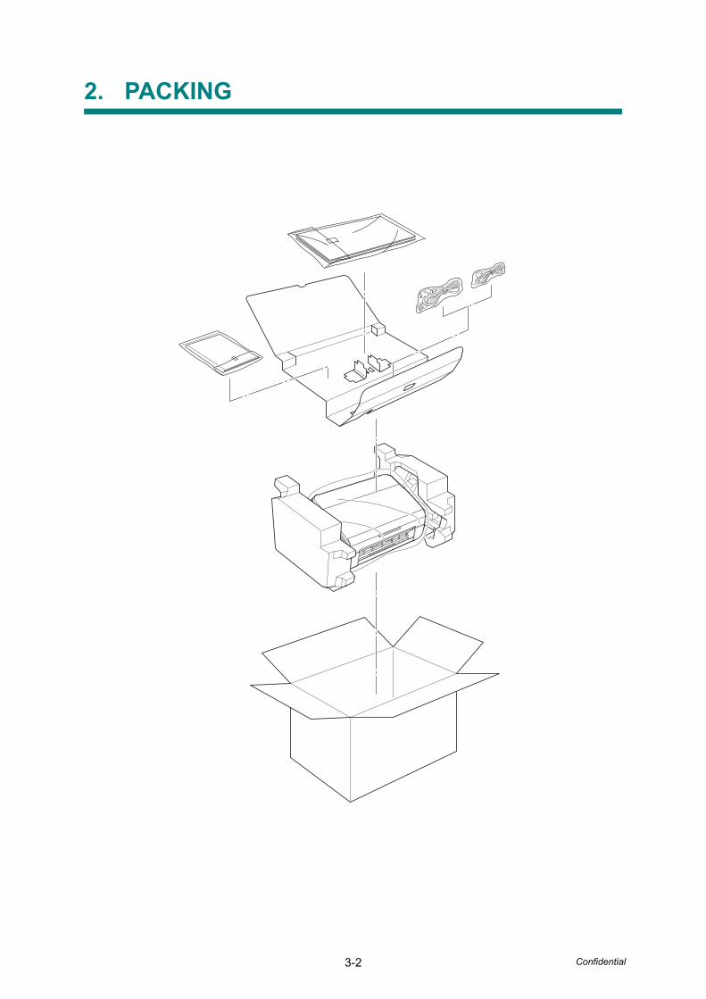
3-2 Confidential
2. PACKING
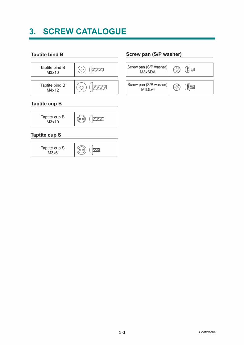
3-3 Confidential
3. SCREW CATALOGUE
Screw pan (S/P washer) Taptite bind B
Taptite cup B
Taptite cup S
Taptite bind BM4x12
Taptite bind BM3x10
Taptite cup BM3x10
Taptite cup SM3x6
Screw pan (S/P washer) M3x6DA
Screw pan (S/P washer) M3.5x6

3-4 Confidential
4. SCREW TORQUE LIST
Note:
• To check the shape of each screw, refer to "3. SCREW CATALOGUE" in this chapter.
Location of screw Screw type Q'tyTightening
torqueN · m (kgf · cm)
Bottom cover Taptite cup B M3x10 4 0.50.1 (51)
Side cover L Taptite cup B M3x10 1 0.50.1 (51)
Side cover R Taptite cup B M3x10 1 0.50.1 (51)
Main PCB shield plateTaptite cup S M3x6
1 0.70.1 (71)
Earth harness (GN) 1 0.70.1 (71)
Main PCB ASSY Taptite cup S M3x6 2 0.70.1 (71)
USB host PCB ASSY Taptite bind B M4x12 2 0.70.1 (71)
Earth harness (BK) Main PCB shield frame
Taptite bind B M3x10 1 0.50.1 (51)
Earth harness (YW) Taptite bind B M3x10 1 0.50.1 (51)
Panel ASSY Taptite bind B M3x10 2 0.50.1 (51)
Top cover sensor holder Taptite bind B M3x10 1 0.50.1 (51)
Upper chute earth spring Taptite cup S M3x6 1 0.70.1 (71)
Double feeding sensor holder Taptite bind B M3x10 2 0.50.1 (51)
Pinch roller support plate Taptite bind B M3x10 2 0.50.1 (51)
Back cover Taptite cup B M3x10 4 0.50.1 (51)
Security slot earth plate Taptite cup B M3x10 1 0.50.1 (51)
Power supply unit Taptite bind B M3x10 4 0.50.1 (51)
Power supply earth harness Screw pan (S/P washer) M3.5x6 1 0.50.1 (51)
Power supply PCB ASSY Taptite cup S M3x6 3 0.40.1 (41)
Earth harness (YW) Taptite cup S M3x6 1 0.40.1 (41)
Lower frame Taptite cup B M3x10 4 0.50.1 (51)
Main motor Screw pan (S/P washer) M3x6 DA 1 0.50.1 (51)
Front cover sensor holder Taptite cup B M3x10 1 0.50.1 (51)
Double feeding sensor upper shield Taptite bind B M3x10 2 0.50.1 (51)
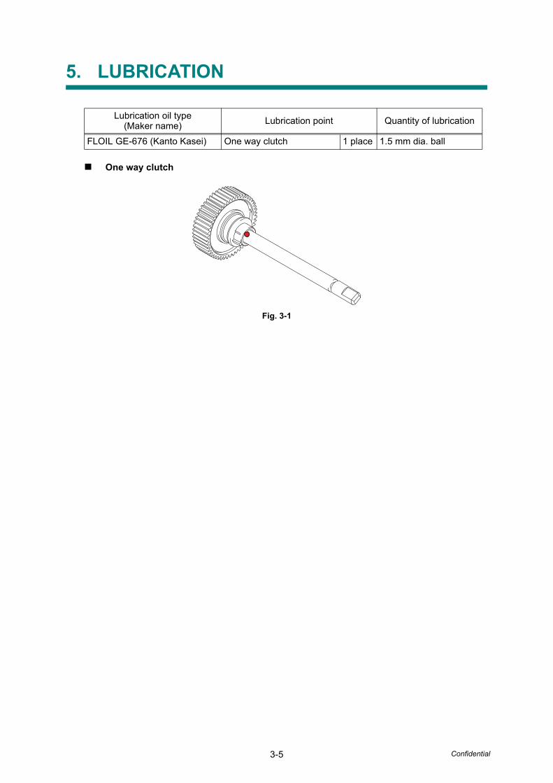
3-5 Confidential
5. LUBRICATION
One way clutch
Fig. 3-1
Lubrication oil type(Maker name) Lubrication point Quantity of lubrication
FLOIL GE-676 (Kanto Kasei) One way clutch 1 place 1.5 mm dia. ball

3-6 Confidential
6. OVERVIEW OF GEARS
Fig. 3-2
One way clutchLD6056
Gear 60/20LD6054
Feed roller gear LD6070
Gear 67LD6053
Eject roller gear LD6070
Gear 40/24LD6052
Gear 20/50LD6051
* Part codes of these gears are subject to change without notice.
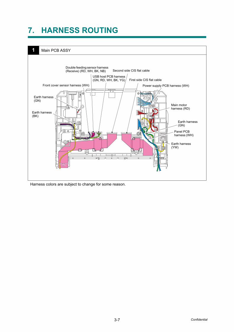
3-7 Confidential
7. HARNESS ROUTING
1 Main PCB ASSY
Harness colors are subject to change for some reason.
Earth harness(BK)
Earth harness(YW)
Earth harness(GN)
Panel PCB harness (WH)
Main motorharness (RD)
Power supply PCB harness (WH)
First side CIS flat cable
Second side CIS flat cable
USB host PCB harness (GN, RD, WH, BK, YG)
Front cover sensor harness (WH)
Earth harness(GN)
Double feeding sensor harness (Receive) (RD, WH, BK, NB)
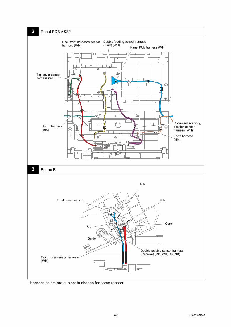
3-8 Confidential
2 Panel PCB ASSY
3 Frame R
Harness colors are subject to change for some reason.
Document detection sensor harness (WH)
Double feeding sensor harness (Sent) (WH)
Panel PCB harness (WH)
Document scanning position sensor harness (WH)
Top cover sensor harness (WH)
Earth harness(GN)
Earth harness(BK)
Front cover sensor harness (WH)
Double feeding sensor harness (Receive) (RD, WH, BK, NB)
Front cover sensor
Guide
Rib
Rib
Rib
Core
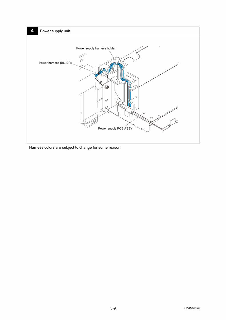
3-9 Confidential
4 Power supply unit
Harness colors are subject to change for some reason.
Power harness (BL, BR)
Power supply harness holder
Power supply PCB ASSY
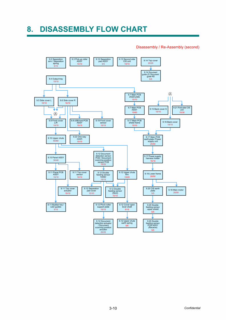
3-10 Confidential
8. DISASSEMBLY FLOW CHART
Disassembly / Re-Assembly (second)
9.2 Separation arm / Separation
spring5/10
9.3 Pick-up roller ASSY10/10
9.12 Separation pad ASSY
5/5
9.13 Second side CIS unit10/10
9.14 Top cover20/20
9.14 Document guide LS / Document
guide RS5/5
9.9 Front cover L/R
10/15
9.8 USB host PCB ASSY15/15
9.19 Front cover sensor10/10
9.22 One way clutch10/10
9.17 Main PCB shield frame
15/10
9.7 Main PCB ASSY15/60
9.7 Main PCB shield plate
10/10
9.21 First side CIS unit
10/30
9.17 Main PCB earth plate / Power
supply unit25/40
9.17 Power supply harness holder
15/15
9.11 Panel PCB ASSY10/10
9.11 Top cover sensor10/10
9.11 Top cover actuator
10/10
9.12 Document detection sensor PCB / Document scanning position
sensor PCB10/20
9.12 Double feeding sensor
holder10/10
9.12 Upper chute film
10/20
9.11 Rubber key / LED guides
5/10
9.12 Separation pad cover
10/10
9.12 Double feeding sensor
(Sent)10/10
9.12 Pinch roller support plate
10/10
9.12 Document detection actuator
/ Document scanning position
actuator20/20
9.12 Cover open lever shaft
5/15
9.12 Upper chute earth spring
5/5
9.20 CIS earth plate5/5
9.20 Double feeding sensor
upper shield5/5
9.20 Double feeding sensor
PCB ASSY (Receive)
5/5
9.4 Output tray15/15
9.5 Side cover L10/10
9.6 Side cover R10/10
9.10 Upper chute60/80
9.10 Panel ASSY30/40
9.15 Back cover S10/10
9.16 Back cover15/15
9.18 Lower frame20/50
9.18 Main motor20/50
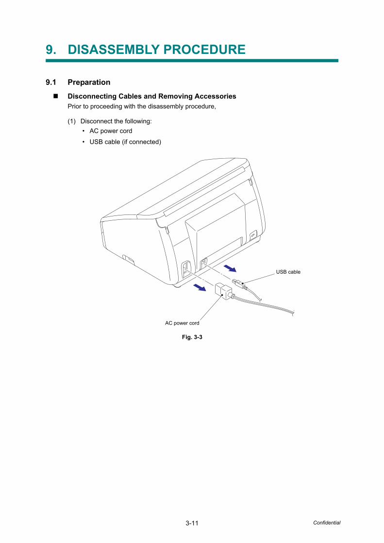
3-11 Confidential
9. DISASSEMBLY PROCEDURE
9.1 Preparation
Disconnecting Cables and Removing AccessoriesPrior to proceeding with the disassembly procedure,
(1) Disconnect the following:
• AC power cord
• USB cable (if connected)
Fig. 3-3
AC power cord
USB cable
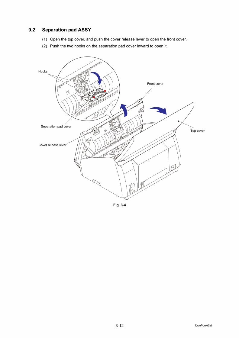
3-12 Confidential
9.2 Separation pad ASSY
(1) Open the top cover, and push the cover release lever to open the front cover.
(2) Push the two hooks on the separation pad cover inward to open it.
Fig. 3-4
Front cover
Top cover
Cover release lever
Separation pad cover
Hooks

3-13 Confidential
(3) Push the two hooks on the separation arm inward to open the separation arm, and remove the separation spring from the front cover.
(4) Push the two hooks on the front cover outward. Remove the two bosses on the separation arm, and remove the separation arm from the front cover.
Fig. 3-5
(5) Close the separation pad cover.
Note:
• Be careful not to damage the separation arm by opening it too much.
• Do not close the front cover when the separation arm is opened to prevent the separation arm to be damaged.
Assembling Note:
• When assembling the separation spring, engage it with ribs on the front cover and separation pad cover.
Hook
Hook
Hook
Separation spring
Front cover
Boss
Separation arm
Boss
Hook
Rib
Separation pad cover
Rib
Separation spring
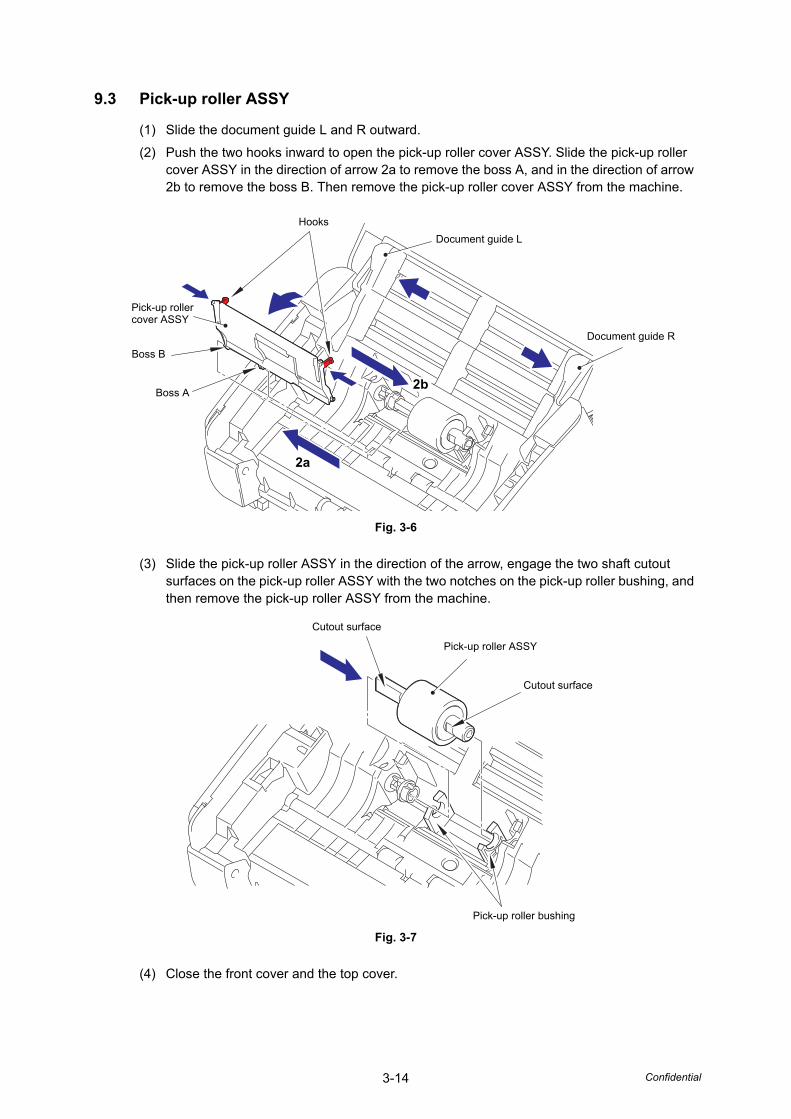
3-14 Confidential
9.3 Pick-up roller ASSY
(1) Slide the document guide L and R outward.
(2) Push the two hooks inward to open the pick-up roller cover ASSY. Slide the pick-up roller cover ASSY in the direction of arrow 2a to remove the boss A, and in the direction of arrow 2b to remove the boss B. Then remove the pick-up roller cover ASSY from the machine.
Fig. 3-6
(3) Slide the pick-up roller ASSY in the direction of the arrow, engage the two shaft cutout surfaces on the pick-up roller ASSY with the two notches on the pick-up roller bushing, and then remove the pick-up roller ASSY from the machine.
Fig. 3-7
(4) Close the front cover and the top cover.
Hooks
Document guide L
Document guide R
Boss B
Pick-up roller cover ASSY
2a
Boss A2b
Pick-up roller ASSY
Cutout surface
Cutout surface
Pick-up roller bushing
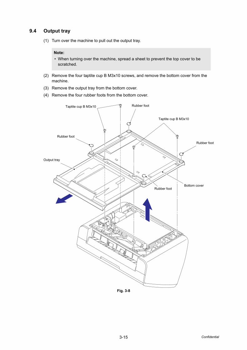
3-15 Confidential
9.4 Output tray
(1) Turn over the machine to pull out the output tray.
(2) Remove the four taptite cup B M3x10 screws, and remove the bottom cover from the machine.
(3) Remove the output tray from the bottom cover.
(4) Remove the four rubber foots from the bottom cover.
Fig. 3-8
Note:
• When turning over the machine, spread a sheet to prevent the top cover to be scratched.
Rubber foot
Taptite cup B M3x10
Rubber foot
Bottom coverRubber foot
Output tray
Rubber foot
Taptite cup B M3x10
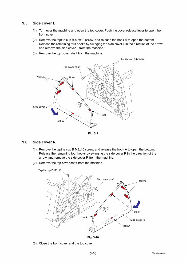
3-16 Confidential
9.5 Side cover L
(1) Turn over the machine and open the top cover. Push the cover release lever to open the front cover.
(2) Remove the taptite cup B M3x10 screw, and release the hook A to open the bottom. Release the remaining four hooks by swinging the side cover L in the direction of the arrow, and remove the side cover L from the machine.
(3) Remove the top cover shaft from the machine.
Fig. 3-9
9.6 Side cover R
(1) Remove the taptite cup B M3x10 screw, and release the hook A to open the bottom. Release the remaining four hooks by swinging the side cover R in the direction of the arrow, and remove the side cover R from the machine.
(2) Remove the top cover shaft from the machine.
Fig. 3-10
(3) Close the front cover and the top cover.
Top cover shaft
Hooks
Side cover L
Hook A
Taptite cup B M3x10
Hook
Hook
Taptite cup B M3x10
Top cover shaft Hooks
Hook A
Side cover R
Hook
Hook
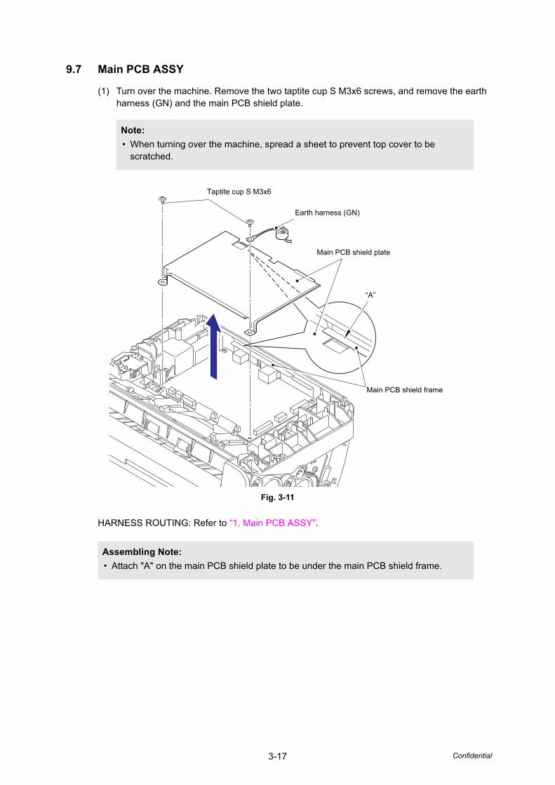
3-17 Confidential
9.7 Main PCB ASSY
(1) Turn over the machine. Remove the two taptite cup S M3x6 screws, and remove the earth harness (GN) and the main PCB shield plate.
Fig. 3-11
HARNESS ROUTING: Refer to “1. Main PCB ASSY”.
Note:
• When turning over the machine, spread a sheet to prevent top cover to be scratched.
Assembling Note:
• Attach "A" on the main PCB shield plate to be under the main PCB shield frame.
Main PCB shield plate
Taptite cup S M3x6
Main PCB shield frame
“A”
Earth harness (GN)

3-18 Confidential
(2) Disconnect all harnesses and flat cables connected to the main PCB ASSY.
Fig. 3-12
HARNESS ROUTING: Refer to “1. Main PCB ASSY”.
(3) Remove the two taptite cup S M3x6 screws to remove the main PCB ASSY from the machine.
Fig. 3-13
Power supply PCB harness
Main motor harness
Panel PCB harness
Second sideCIS flat cable
USB hostPCB harness
Double feeding sensor harness (Receive)
Front coversensor harness
First side CIS flat cable
Main PCB ASSY
Taptite cup S M3x6
Main PCB ASSY

3-19 Confidential
9.8 USB host PCB ASSY
(1) Remove the taptite bind B M3x10 screw to remove the earth harness (BK).
(2) Release the USB host PCB harness, the earth harness (BK), the double feeding sensor harness (Receive), and the front cover sensor harness from the securing fixtures.
(3) Remove the two taptite bind B M4x12 screws. Lift the USB earth plate to remove the USB host PCB ASSY from the machine.
Fig. 3-14
HARNESS ROUTING: Refer to “1. Main PCB ASSY” and “3. Frame R”.
Note:
• Be careful not to deform the USB earth plate.
Taptite bind B M3x10
Taptite bind B M4x12
Earth harness (BK)
USB host PCB ASSY
USB earth plate
USB host PCB harness
Double feeding sensor harness (Receive)
Front cover sensor harness
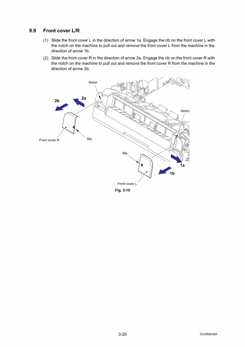
3-20 Confidential
9.9 Front cover L/R
(1) Slide the front cover L in the direction of arrow 1a. Engage the rib on the front cover L with the notch on the machine to pull out and remove the front cover L from the machine in the direction of arrow 1b.
(2) Slide the front cover R in the direction of arrow 2a. Engage the rib on the front cover R with the notch on the machine to pull out and remove the front cover R from the machine in the direction of arrow 2b.
Fig. 3-15
Rib
Notch
Front cover R
Rib
Notch
Front cover L
2a2b
1b
1a
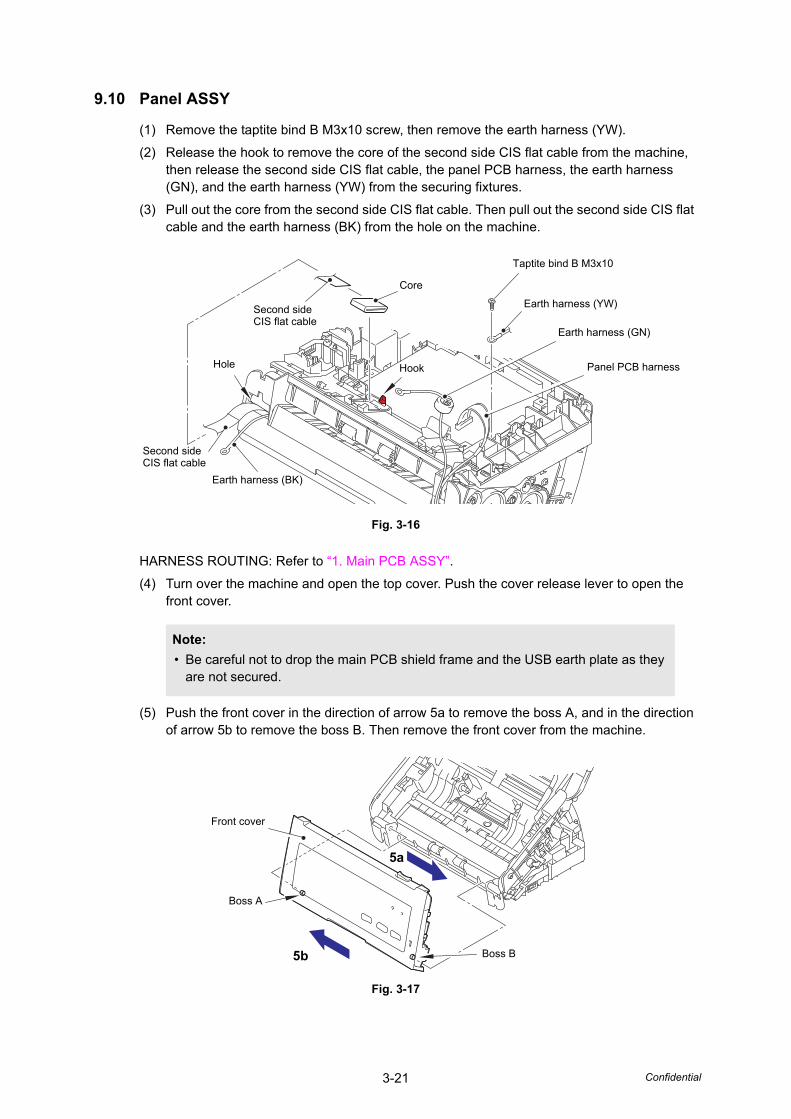
3-21 Confidential
9.10 Panel ASSY
(1) Remove the taptite bind B M3x10 screw, then remove the earth harness (YW).
(2) Release the hook to remove the core of the second side CIS flat cable from the machine, then release the second side CIS flat cable, the panel PCB harness, the earth harness (GN), and the earth harness (YW) from the securing fixtures.
(3) Pull out the core from the second side CIS flat cable. Then pull out the second side CIS flat cable and the earth harness (BK) from the hole on the machine.
Fig. 3-16
HARNESS ROUTING: Refer to “1. Main PCB ASSY”.
(4) Turn over the machine and open the top cover. Push the cover release lever to open the front cover.
(5) Push the front cover in the direction of arrow 5a to remove the boss A, and in the direction of arrow 5b to remove the boss B. Then remove the front cover from the machine.
Fig. 3-17
Note:
• Be careful not to drop the main PCB shield frame and the USB earth plate as they are not secured.
Core
Earth harness (BK)
Earth harness (YW)
Taptite bind B M3x10
Hole
Second sideCIS flat cable
Panel PCB harness
Second sideCIS flat cable
Hook
Earth harness (GN)
Boss A
Front cover
Boss B
5a
5b
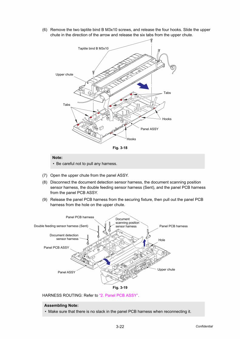
3-22 Confidential
(6) Remove the two taptite bind B M3x10 screws, and release the four hooks. Slide the upper chute in the direction of the arrow and release the six tabs from the upper chute.
Fig. 3-18
(7) Open the upper chute from the panel ASSY.
(8) Disconnect the document detection sensor harness, the document scanning position sensor harness, the double feeding sensor harness (Sent), and the panel PCB harness from the panel PCB ASSY.
(9) Release the panel PCB harness from the securing fixture, then pull out the panel PCB harness from the hole on the upper chute.
Fig. 3-19
HARNESS ROUTING: Refer to “2. Panel PCB ASSY”.
Note:
• Be careful not to pull any harness.
Assembling Note:
• Make sure that there is no slack in the panel PCB harness when reconnecting it.
Taptite bind B M3x10
Panel ASSY
Hooks
Hooks
Tabs
Upper chute
Tabs
Panel PCB harness
Hole
Upper chute
Panel PCB harness
Double feeding sensor harness (Sent)
Document detectionsensor harness
Panel ASSY
Panel PCB ASSY
Document scanning position sensor harness
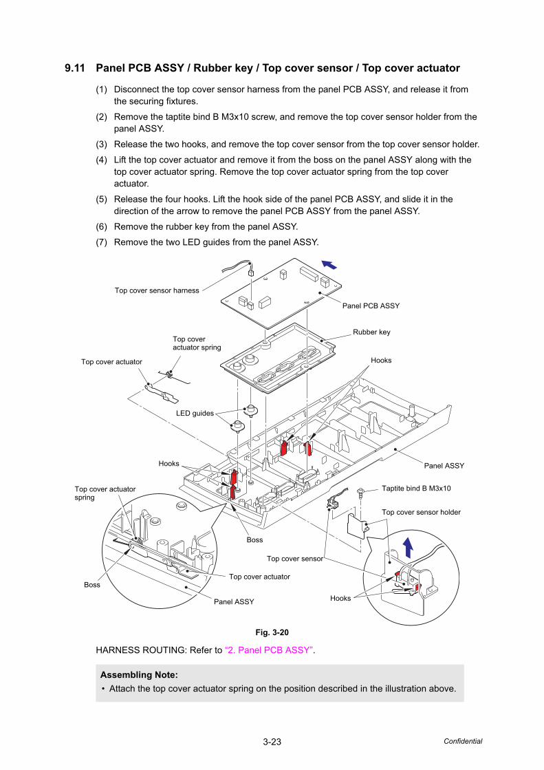
3-23 Confidential
9.11 Panel PCB ASSY / Rubber key / Top cover sensor / Top cover actuator
(1) Disconnect the top cover sensor harness from the panel PCB ASSY, and release it from the securing fixtures.
(2) Remove the taptite bind B M3x10 screw, and remove the top cover sensor holder from the panel ASSY.
(3) Release the two hooks, and remove the top cover sensor from the top cover sensor holder.
(4) Lift the top cover actuator and remove it from the boss on the panel ASSY along with the top cover actuator spring. Remove the top cover actuator spring from the top cover actuator.
(5) Release the four hooks. Lift the hook side of the panel PCB ASSY, and slide it in the direction of the arrow to remove the panel PCB ASSY from the panel ASSY.
(6) Remove the rubber key from the panel ASSY.
(7) Remove the two LED guides from the panel ASSY.
Fig. 3-20
HARNESS ROUTING: Refer to “2. Panel PCB ASSY”.
Assembling Note:
• Attach the top cover actuator spring on the position described in the illustration above.
Panel PCB ASSY
Top cover sensor harness
Rubber key
Hooks
Panel ASSY
Top cover sensor holder
Taptite bind B M3x10
Top cover actuator
Top cover sensor
Top cover actuatorspring
Panel ASSY
Top cover actuator spring
Hooks
Top cover actuator
LED guides
Boss
Boss
Hooks
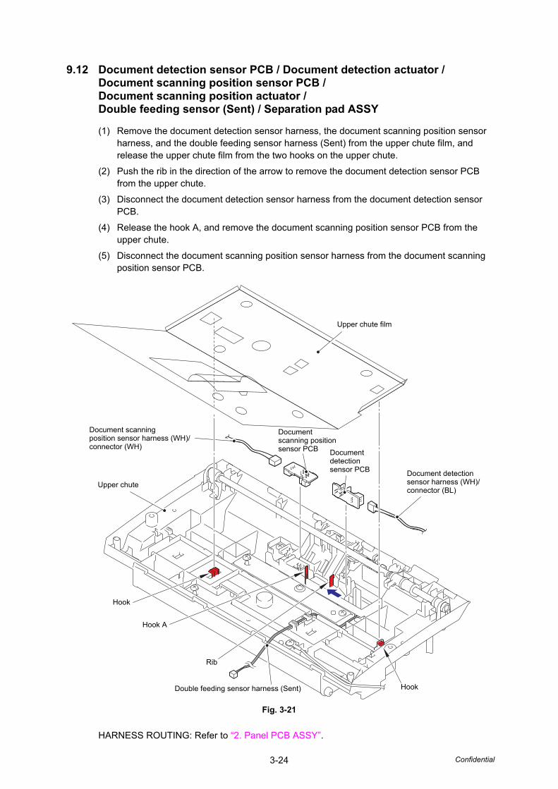
3-24 Confidential
9.12 Document detection sensor PCB / Document detection actuator /Document scanning position sensor PCB /Document scanning position actuator /Double feeding sensor (Sent) / Separation pad ASSY
(1) Remove the document detection sensor harness, the document scanning position sensor harness, and the double feeding sensor harness (Sent) from the upper chute film, and release the upper chute film from the two hooks on the upper chute.
(2) Push the rib in the direction of the arrow to remove the document detection sensor PCB from the upper chute.
(3) Disconnect the document detection sensor harness from the document detection sensor PCB.
(4) Release the hook A, and remove the document scanning position sensor PCB from the upper chute.
(5) Disconnect the document scanning position sensor harness from the document scanning position sensor PCB.
Fig. 3-21
HARNESS ROUTING: Refer to “2. Panel PCB ASSY”.
Upper chute film
Hook A
Document scanning position sensor harness (WH)/connector (WH)
Document detection sensor harness (WH)/connector (BL)
Document detection sensor PCB
Document scanning position sensor PCB
Upper chute
Double feeding sensor harness (Sent)
Rib
Hook
Hook
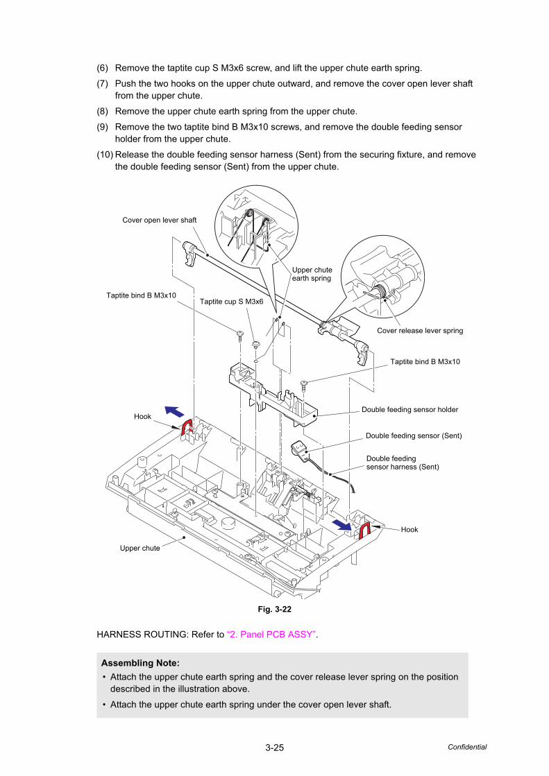
3-25 Confidential
(6) Remove the taptite cup S M3x6 screw, and lift the upper chute earth spring.
(7) Push the two hooks on the upper chute outward, and remove the cover open lever shaft from the upper chute.
(8) Remove the upper chute earth spring from the upper chute.
(9) Remove the two taptite bind B M3x10 screws, and remove the double feeding sensor holder from the upper chute.
(10) Release the double feeding sensor harness (Sent) from the securing fixture, and remove the double feeding sensor (Sent) from the upper chute.
Fig. 3-22
HARNESS ROUTING: Refer to “2. Panel PCB ASSY”.
Assembling Note:
• Attach the upper chute earth spring and the cover release lever spring on the position described in the illustration above.
• Attach the upper chute earth spring under the cover open lever shaft.
Hook
Cover open lever shaft
Upper chute earth spring
Double feeding sensor holder
Double feeding sensor (Sent)
Hook
Taptite bind B M3x10Taptite cup S M3x6
Taptite bind B M3x10
Upper chute
Double feeding sensor harness (Sent)
Cover release lever spring

3-26 Confidential
(11) Push the two hooks on the separation pad cover inward to open the separation pad cover.
(12) Engage the separation pad cover with the groove on the upper chute, and slide it in the direction of arrow 12b while pulling its shaft in the direction of arrow 12a using spring peg or other tools. Remove the cutout surface on the separation pad cover shaft from the rib on the upper chute. Then remove the shaft on the left side of the separation pad cover to remove it from the upper chute in the direction of arrow 12c.
Fig. 3-23
(13) Push both of the two hooks on the separation pad ASSY inward, and remove the separation pad ASSY from the separation pad cover.
Fig. 3-24
Upper chute
Separation pad cover
Hook
Hook
Cutout surface
Rib
Groove
12b
12c
12a
Hooks
Separation pad ASSY
Separation pad cover
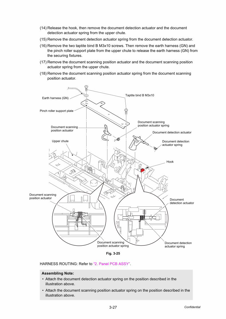
3-27 Confidential
(14) Release the hook, then remove the document detection actuator and the document detection actuator spring from the upper chute.
(15) Remove the document detection actuator spring from the document detection actuator.
(16) Remove the two taptite bind B M3x10 screws. Then remove the earth harness (GN) and the pinch roller support plate from the upper chute to release the earth harness (GN) from the securing fixtures.
(17) Remove the document scanning position actuator and the document scanning position actuator spring from the upper chute.
(18) Remove the document scanning position actuator spring from the document scanning position actuator.
Fig. 3-25
HARNESS ROUTING: Refer to “2. Panel PCB ASSY”.
Assembling Note:
• Attach the document detection actuator spring on the position described in the illustration above.
• Attach the document scanning position actuator spring on the position described in the illustration above.
Taptite bind B M3x10
Upper chute
Document scanning position actuator spring
Document detection actuator spring
Hook
Document scanning position actuator
Pinch roller support plate
Earth harness (GN)
Document detection actuator
Document detection actuator spring
Document detection actuator
Document scanning position actuator
Document scanningposition actuator spring
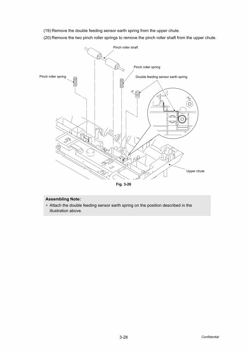
3-28 Confidential
(19) Remove the double feeding sensor earth spring from the upper chute.
(20) Remove the two pinch roller springs to remove the pinch roller shaft from the upper chute.
Fig. 3-26
Assembling Note:
• Attach the double feeding sensor earth spring on the position described in the illustration above.
Pinch roller shaft
Pinch roller spring Double feeding sensor earth spring
Pinch roller spring
Upper chute

3-29 Confidential
9.13 Second side CIS unit
(1) Turn over the upper chute.
(2) Release the two hooks, lift the second side CIS unit, and disconnect the second side CIS flat cable from it.
(3) Pull out the second side CIS flat cable from the hole on the upper chute.
(4) Remove the CIS spring from the upper chute.
Fig. 3-27
Second side CIS unit
Hook
Upper chute
Hook
Second side CIS flat cable
Second side CIS flat cable
CIS spring
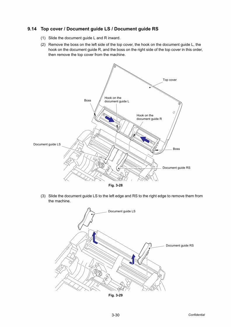
3-30 Confidential
9.14 Top cover / Document guide LS / Document guide RS
(1) Slide the document guide L and R inward.
(2) Remove the boss on the left side of the top cover, the hook on the document guide L, the hook on the document guide R, and the boss on the right side of the top cover in this order, then remove the top cover from the machine.
Fig. 3-28
(3) Slide the document guide LS to the left edge and RS to the right edge to remove them from the machine.
Fig. 3-29
Document guide RS
BossHook on the document guide L
Hook on the document guide R
Top cover
Boss
Document guide LS
Document guide RS
Document guide LS
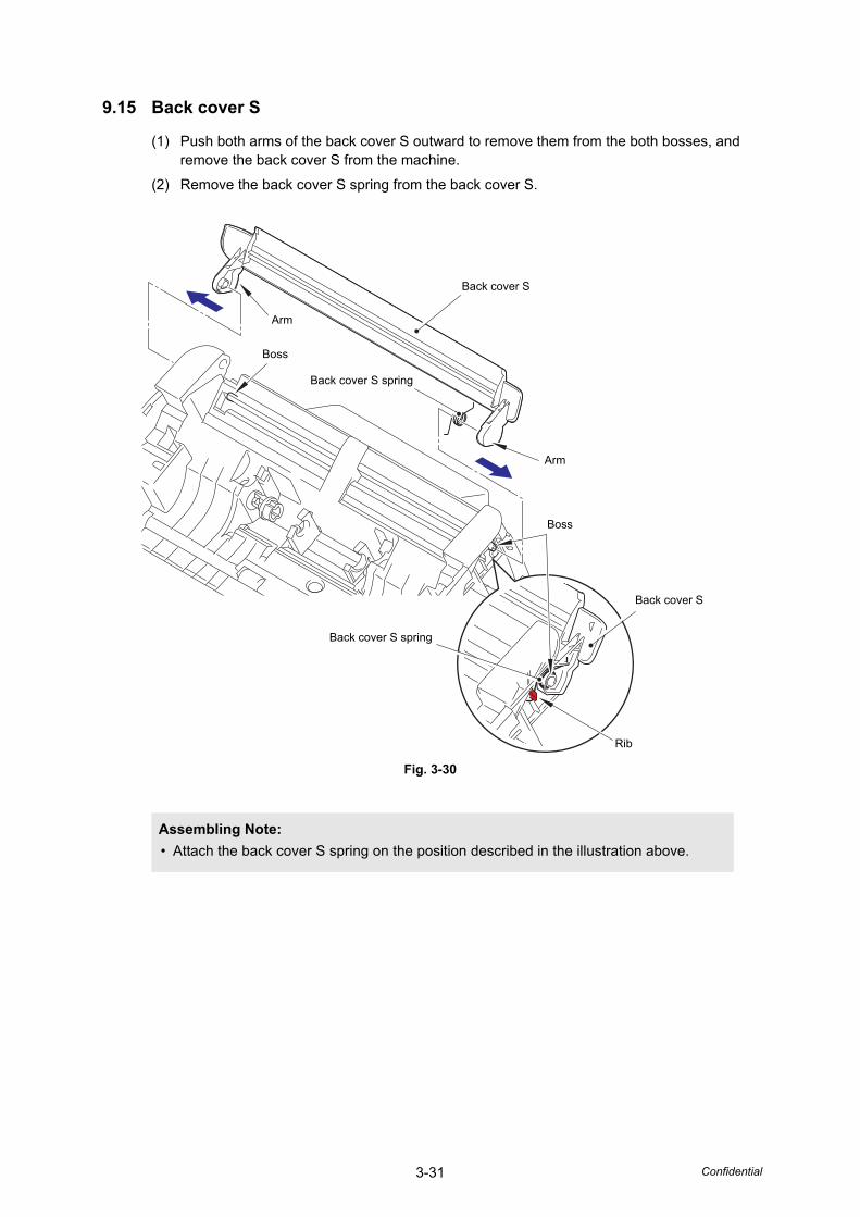
3-31 Confidential
9.15 Back cover S
(1) Push both arms of the back cover S outward to remove them from the both bosses, and remove the back cover S from the machine.
(2) Remove the back cover S spring from the back cover S.
Fig. 3-30
Assembling Note:
• Attach the back cover S spring on the position described in the illustration above.
Back cover S
Arm
Arm
Boss
Boss
Back cover S spring
Back cover S
Back cover S spring
Rib

3-32 Confidential
9.16 Back cover
(1) Remove the four taptite cup B M3x10 screws, and release the two hooks A to open the bottom. Then release the upper three hooks from the three ribs to remove the back cover from the machine.
(2) Remove the taptite cup B M3x10 screw, and remove the security slot earth plate from the back cover.
Fig. 3-31
Hooks
Taptite cup B M3x10
Hook A
Security slot earth plate
Taptite cup B M3x10
Taptite cup B M3x10
Hook A
Ribs
Back cover

3-33 Confidential
9.17 Power supply PCB ASSY
(1) Turn over the machine to remove the main PCB shield frame and the USB earth plate from it.
Fig. 3-32
Assembling Note:
• Engage the two hooks on the machine with the main PCB shield frame when attaching.
Main PCB shield frame
USB earth plate
Main PCB shield frame
Hook
Hook

3-34 Confidential
(2) Disconnect the power supply PCB harness from the guide behind the machine, and pull it out from the hole on the machine.
(3) Remove the screw pan (S/P washer) M3.5x6 screw and the four taptite bind B M3x10 screws to remove the power supply earth harness, the main PCB earth plate, and the power supply unit from the machine.
Fig. 3-33
Taptite bind B M3x10
Taptite bind B M3x10
Power supply unit
Screw pan (S/P washer) M3.5x6
Main PCB earth plate
Power supply earth harness
Power supply PCB harness
Hole
Guides
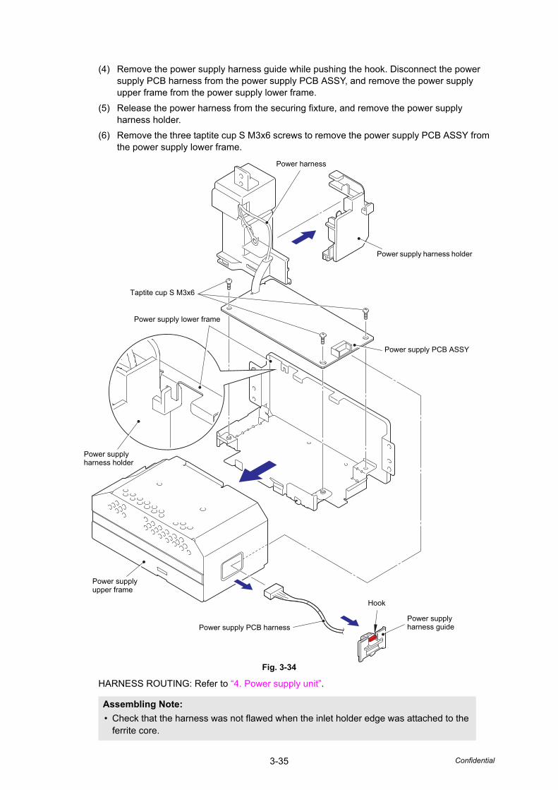
3-35 Confidential
(4) Remove the power supply harness guide while pushing the hook. Disconnect the power supply PCB harness from the power supply PCB ASSY, and remove the power supply upper frame from the power supply lower frame.
(5) Release the power harness from the securing fixture, and remove the power supply harness holder.
(6) Remove the three taptite cup S M3x6 screws to remove the power supply PCB ASSY from the power supply lower frame.
Fig. 3-34
HARNESS ROUTING: Refer to “4. Power supply unit”.
Assembling Note:
• Check that the harness was not flawed when the inlet holder edge was attached to the ferrite core.
Taptite cup S M3x6
Power supply harness holder
Power supply PCB ASSY
Power supply harness holder
Power supply PCB harnessPower supplyharness guide
Hook
Power supply lower frame
Power supply upper frame
Power harness
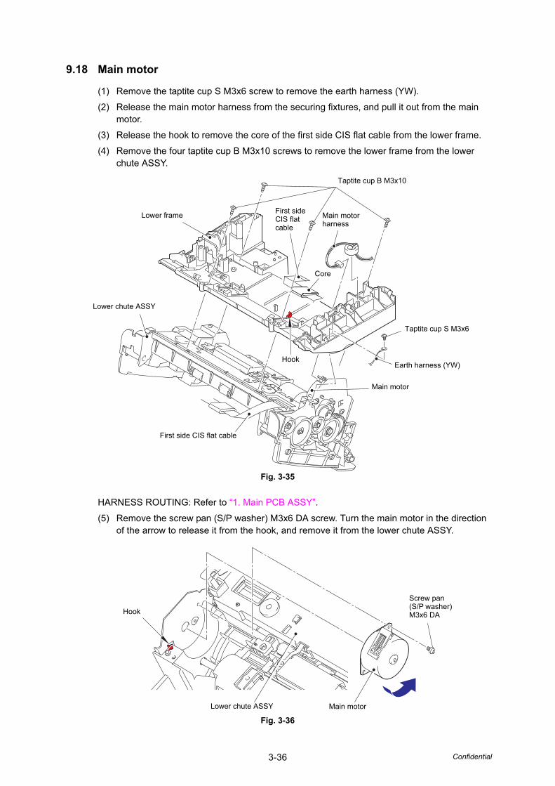
3-36 Confidential
9.18 Main motor
(1) Remove the taptite cup S M3x6 screw to remove the earth harness (YW).
(2) Release the main motor harness from the securing fixtures, and pull it out from the main motor.
(3) Release the hook to remove the core of the first side CIS flat cable from the lower frame.
(4) Remove the four taptite cup B M3x10 screws to remove the lower frame from the lower chute ASSY.
Fig. 3-35
HARNESS ROUTING: Refer to “1. Main PCB ASSY”.
(5) Remove the screw pan (S/P washer) M3x6 DA screw. Turn the main motor in the direction of the arrow to release it from the hook, and remove it from the lower chute ASSY.
Fig. 3-36
First side CIS flat cable
Main motor harness
Taptite cup B M3x10
Taptite cup S M3x6
Earth harness (YW)Hook
Core
Lower frame
Main motor
Lower chute ASSY
First side CIS flat cable
Lower chute ASSY
Screw pan (S/P washer) M3x6 DA
Main motor
Hook
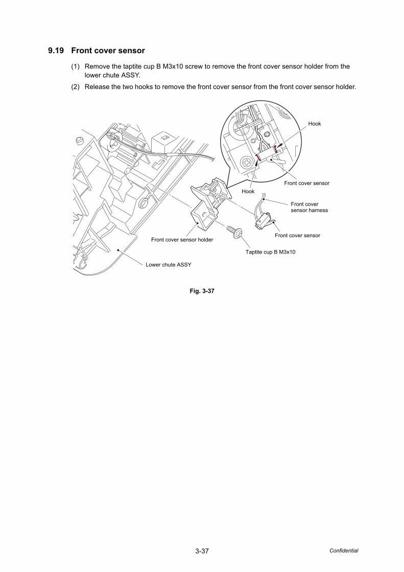
3-37 Confidential
9.19 Front cover sensor
(1) Remove the taptite cup B M3x10 screw to remove the front cover sensor holder from the lower chute ASSY.
(2) Release the two hooks to remove the front cover sensor from the front cover sensor holder.
Fig. 3-37
Hook
Front cover sensor
Hook
Taptite cup B M3x10
Front cover sensor holder
Lower chute ASSY
Front cover sensor
Front cover sensor harness
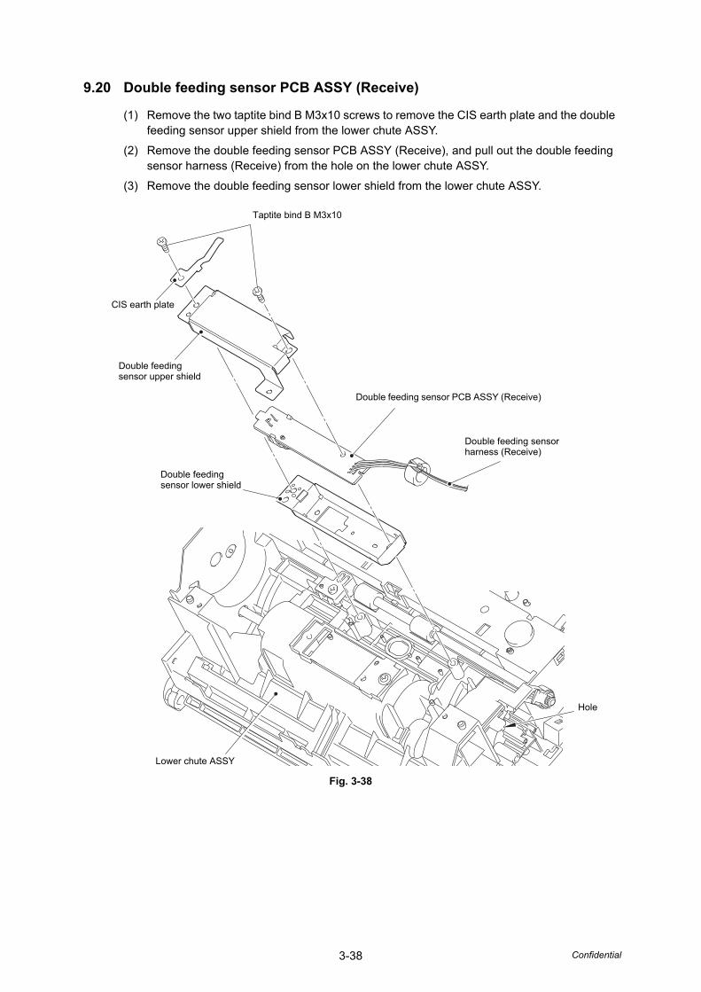
3-38 Confidential
9.20 Double feeding sensor PCB ASSY (Receive)
(1) Remove the two taptite bind B M3x10 screws to remove the CIS earth plate and the double feeding sensor upper shield from the lower chute ASSY.
(2) Remove the double feeding sensor PCB ASSY (Receive), and pull out the double feeding sensor harness (Receive) from the hole on the lower chute ASSY.
(3) Remove the double feeding sensor lower shield from the lower chute ASSY.
Fig. 3-38
Taptite bind B M3x10
Double feeding sensor PCB ASSY (Receive)
Double feeding sensor harness (Receive)
Double feeding sensor upper shield
CIS earth plate
Lower chute ASSY
Double feeding sensor lower shield
Hole

3-39 Confidential
9.21 First side CIS unit
(1) Turn over the lower chute ASSY. Release the hook from the hole on the lower chute ASSY, and remove the first side CIS unit from the lower chute ASSY while lifting and pulling it in the direction of the arrow. Then, pull out the first side CIS flat cable from the hole on the lower chute ASSY.
(2) Disconnect the first side CIS flat cable from the first side CIS unit.
Fig. 3-39
First side CIS unit
Hook
Lower chute ASSY
Hole
First side CIS flat cable
Hole

3-40 Confidential
9.22 One way clutch
(1) Release the hook to remove the gear 60/20 from the lower chute ASSY.
(2) Release the hook to remove the one way clutch from the lower chute ASSY.
Fig. 3-40
Assembling Note:
• When attaching the one way clutch, engage the separate roller shaft with the hole on the gear, and push the shaft in the direction of the arrow.
Separate roller shaft
One way clutch
Hook
Gear 60/20
Hook
Lower chute ASSY

Confidential
CHAPTER 4ADJUSTING AND UPDATING SETTINGS
AS REQUIRED AFTER PARTS REPLACEMENT

Confidential
CHAPTER 4 ADJUSTING AND UPDATING SETTINGS AS REQUIRED AFTER PARTS REPLACEMENT
This chapter describes adjustments and updating of settings, which are required if the main PCB ASSY and some other parts have been replaced.
CONTENTS1. IF YOU REPLACE THE MAIN PCB ASSY...................................................................4-1
1.1 Installing Firmware ................................................................................................4-2
1.1.1 Checking firmware version .........................................................................4-2
1.1.2 Installing firmware ......................................................................................4-3
1.2 Setting by Country .................................................................................................4-4
1.3 Initializing the EEPROM of the Main PCB ASSY ..................................................4-4
1.4 Setting Serial Number ...........................................................................................4-5
1.5 Acquiring White Level Data ...................................................................................4-6
1.6 Setting Double Feeding Sensor Threshold............................................................4-7
1.7 Checking Operation after Repair ...........................................................................4-8
2. IF YOU REPLACE THE CIS UNIT ..............................................................................4-10
2.1 Checking Firmware Version.................................................................................4-10
2.2 Acquiring White Level Data ................................................................................. 4-11
2.3 Checking Operation after Repair .........................................................................4-12
3. IF YOU REPLACE THE DOUBLE FEEDING SENSOR.............................................4-14
3.1 Setting Double Feeding Sensor Threshold..........................................................4-14
3.2 Checking Double Feeding Sensor Operation ......................................................4-15
4. IF YOU REPLACE THE PANEL ASSY.......................................................................4-16
4.1 Acquiring White Level Data for Second Side CIS Unit ........................................4-16
4.2 Checking Operation after Repair .........................................................................4-17
5. IF YOU REPLACE THE PICK-UP ROLLER / SEPARATION PAD ............................4-18
5.1 Resetting Pick-up Roller / Separation Pad Counters...........................................4-18
4-1 Confidential
1. IF YOU REPLACE THE MAIN PCB ASSY
<What to do after replacement>
• Installing firmware
• Setting by country
• Initializing the EEPROM of the main PCB ASSY
• Setting serial number
• Acquiring white level data
• Setting double feeding sensor threshold
• Checking operation after repair
What you need to prepare
(1) One USB cable
(2) Create a temporary folder on the C drive of the computer (Windows® XP or higher).
(3) Service setting tool (brusbsn.zip)Copy this file into the temporary folder created on the C drive.
(4) Download utility (Filedg32.exe)Copy this file into the temporary folder created on the C drive.
(5) Maintenance driver (MaintenanceDriver.zip)When the maintenance driver is not installed on the computer to be used, copy this file into the temporary folder created on the C drive, and extract the copied file. Refer to "APPENDIX 3 INSTALLING MAINTENANCE DRIVER" for the installation procedure.
(6) Firmware
(7) Country code setting PJL fileCopy this file into the temporary folder created on the C drive.
(8) Remote check mode file (brmfrmss.exe)Copy this file into the temporary folder created on the C drive.
(9) Sheet for double feeding sensor threshold setting (LD6340001)
(10) Double feeding sensor threshold setting tool (BrADSmt1.exe)Copy this file into the temporary folder created on the C drive.
(11) Scan limit sample.
(12) Test chart DS-001(LD1625001)
Main firmware:(E.g.) LZXXXX_$.upd
LZXXXX : First six digits of the part number of the firmware$ : Alphabetic character representing the revision version of the firmware

4-2 Confidential
1.1 Installing Firmware
1.1.1 Checking firmware version
Check whether the firmware installed on the main PCB is the latest version. If it is the latest version, there is no need to install the firmware. If it is not, be sure to install the firmware to the main PCB as described in "1.1.2 Installing firmware" in this chapter.
<How to check firmware version>
(1) Press and hold the [Stop] and [Scan to USB] buttons simultaneously, and plug the AC power cord into the outlet. Check that the Power LED and the Error LED are lit, and release these two buttons.
(2) Press the [Stop], [Scan to USB], [Scan to PC], and [Stop] buttons in this order. The Scan to USB LED and the Scan to PC LED light.
(3) Press the [Scan to PC] button. The Scan to USB LED and the Scan to PC LED go out.
(4) Turn ON the power switch of the computer.
(5) Connect the computer to the machine with the USB cable.
(6) Press and hold the [Stop] button until the Power LED lights.
(7) Double-click "brmfrmss.exe" that was copied into the temporary folder to start remote check mode. The screen shown below appears.
(8) Click the [Machine Info.] tab. The firmware version is displayed.
Note:
• To use remote check mode, the computer needs to be connected to the machine with the USB cable and the power switch of the computer must be turned ON before proceeding to step 6.

4-3 Confidential
1.1.2 Installing firmware
(1) Press and hold the [Stop] and [Scan to PC] buttons simultaneously, and plug the AC power cord into the outlet. Check that the Power LED and the Error LED are lit, and release these two buttons.
(2) Press the [Scan to PC] button, and then the [Stop] button. The Scan to PC LED light, and the machine enters firmware installing mode.
(3) Connect the computer to the machine with the USB cable.
(4) Turn ON the power switch of the computer.
(5) Open the temporary folder and double-click "Filedg32.exe" to start it, and select the "Brother Maintenance USB Printer".
(6) Drag and drop the firmware (LZXXXX_$.upd) in the same folder onto the "Brother Maintenance USB Printer" icon. The firmware file is loaded to the machine, and installing to the flash ROM starts.
(7) The LED flashes randomly during installing. When installing is completed, the machine restarts and returns to the ready state automatically. Do not disconnect the USB cable or turn OFF the power switch of the computer until installing is completed.
(8) Unplug the AC power cord of the machine, and disconnect the USB cable.
4-4 Confidential
1.2 Setting by Country
(1) Press and hold the [Stop] and [Scan to USB] buttons simultaneously, and plug the AC power cord into the outlet. Check that the Power LED and the Error LED are lit, and release these two buttons.
(2) Press the [Stop], [Scan to USB], [Scan to PC], and [Stop] buttons in this order. The Scan to PC LED and the Scan to USB LED light.
(3) Press the [Scan to PC] button. The Scan to PC LED and the Scan to USB LED go out.
(4) Connect the computer to the machine with the USB cable.
(5) Turn ON the power switch of the computer.
(6) Press and hold the [Stop] button until the Power LED lights.
(7) Open the temporary folder and double-click "Filedg32.exe" to start it, and select the "Brother Maintenance USB Printer".
(8) Drag and drop the Country code setting PJL file in the temporary folder onto the "Brother Maintenance USB Printer" icon. The country code information is loaded to the machine and written to the flash ROM.
(9) Wait for several seconds, and the country code that has been set is displayed on the computer screen.
(10) Unplug the AC power cord of the machine, and disconnect the USB cable.
1.3 Initializing the EEPROM of the Main PCB ASSY
(1) Press and hold the [Stop] and [Scan to USB] buttons simultaneously, and plug the AC power cord into the outlet. Check that the Power LED and the Error LED are lit, and release these two buttons.
(2) Press the [Stop], [Scan to USB], [Scan to PC], and [Stop] buttons in this order. The Scan to PC LED and the Scan to USB LED light.
(3) Press the [Scan to PC] button. The Scan to PC LED and the Scan to USB LED go out, and the machine enters maintenance mode for service personnel.
(4) Press the [Scan to USB] button three times. The Scan to PC LED and the Scan to USB LED light.
(5) Press the [Stop] button. The EEPROM of the main PCB ASSY is initialized.
(6) Unplug the AC power cord of the machine.

4-5 Confidential
1.4 Setting Serial Number
(1) Press and hold the [Stop] and [Scan to USB] buttons simultaneously, and plug the AC power cord into the outlet. Check that the Power LED and the Error LED are lit, and release these two buttons.
(2) Press the [Stop], [Scan to USB], [Scan to PC], and [Stop] buttons in this order. The Scan to PC LED and the Scan to USB LED light.
(3) Press the [Scan to PC] button. The Scan to PC LED and the Scan to USB LED go out, and the machine enters maintenance mode for service personnel.
(4) Connect the computer to the machine with the USB cable.
(5) Turn ON the power switch of the computer.
(6) Press the [Stop] button. The Power LED and the Scan to USB LED light, and the machine enters function number selection mode.
(7) Extract the "brusbsn.zip" file that was copied into the temporary folder, and double-click "brusbsn.exe" to start it.
(8) In the [Product Category] field, select the [4 Other - Model].
(9) Select [ADS 2012 MODEL] in the left bottom field of the BrUsbSn.
(10) In the [Port] field, select the port number assigned to the Brother Maintenance USB Printer. If the port number is unknown, follow the steps below to check it.
1) Click [Start], [Settings], and [Printers and Faxes]. The Printers and Faxes window appears.
2) Right-click the "Brother Maintenance USB Printer" icon.
3) Click [Properties]. The Brother Maintenance USB Printer Properties window appears.
4) Click the [Ports] tab. The Brother Maintenance USB Printer port number is displayed.
(11) Enter the serial number (15 digits) of the machine in the [Serial No] field, and click the [OK] button.
(12) Check that the CHECK window appeared on the screen, and click the [Yes] button. The serial number is written to the machine.
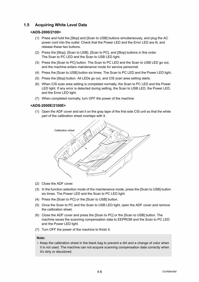
4-6 Confidential
1.5 Acquiring White Level Data
<ADS-2000/2100>
(1) Press and hold the [Stop] and [Scan to USB] buttons simultaneously, and plug the AC power cord into the outlet. Check that the Power LED and the Error LED are lit, and release these two buttons.
(2) Press the [Stop], [Scan to USB], [Scan to PC], and [Stop] buttons in this order. The Scan to PC LED and the Scan to USB LED light.
(3) Press the [Scan to PC] button. The Scan to PC LED and the Scan to USB LED go out, and the machine enters maintenance mode for service personnel.
(4) Press the [Scan to USB] button six times. The Scan to PC LED and the Power LED light.
(5) Press the [Stop] button. All LEDs go out, and CIS scan area setting starts.
(6) When CIS scan area setting is completed normally, the Scan to PC LED and the Power LED light. If any error is detected during setting, the Scan to USB LED, the Power LED, and the Error LED light.
(7) When completed normally, turn OFF the power of the machine.
<ADS-2000E/2100E>
(1) Open the ADF cover and set it on the gray tape of the first side CIS unit so that the white part of the calibration sheet overlaps with it.
(2) Close the ADF cover.
(3) In the function selection mode of the maintenance mode, press the [Scan to USB] button six times. The Power LED and the Scan to PC LED light.
(4) Press the [Scan to PC] or the [Scan to USB] button.
(5) Once the Scan to PC and the Scan to USB LED light, open the ADF cover and remove the calibration sheet.
(6) Close the ADF cover and press the [Scan to PC] or the [Scan to USB] button. The machine saves the scanning compensation data to EEPROM and the Scan to PC LED and the Power LED light.
(7) Turn OFF the power of the machine to finish it.
Note:
• Keep the calibration sheet in the black bag to prevent a dirt and a change of color when it is not used. The machine can not acquire scanning compensation data correctly when it's dirty or discolored.
Calibration sheet

4-7 Confidential
1.6 Setting Double Feeding Sensor Threshold
(1) Press and hold the [Stop] and [Scan to USB] buttons simultaneously, and plug the AC power cord into the outlet. Check that the Power LED and the Error LED are lit, and release these two buttons.
(2) Press the [Stop], [Scan to USB], [Scan to PC], and [Stop] buttons in this order. The Scan to USB LED and the Scan to PC LED light.
(3) Turn ON the power switch of the computer.
(4) Connect the computer to the machine with the USB cable.
(5) Double-click "BrADSmt1.exe" that was copied into the temporary folder to start it.
(6) Select the model name in the [Select model:] box, and click the [Start] button. The double feeding sensor threshold is set.
(7) Set the sheet for double feeding sensor threshold setting in the ADF, and execute the maintenance mode function "Check ADF".Refer to "1.3.3 Check ADF" in Chapter 5.
(8) Execute the maintenance mode function "Acquire white level data and set CIS scan area".Refer to "1.3.5 Acquire white level data and set CIS scan area" in Chapter 5.
(9) Click the [Yes] button. The double feeding sensor threshold is calculated and stored in the EEPROM of the main PCB.
When the setting is completed normally, "OK" is displayed on the screen.If any error is detected during setting, "ERROR" is displayed on the screen.
(10) Unplug the AC power cord of the machine.
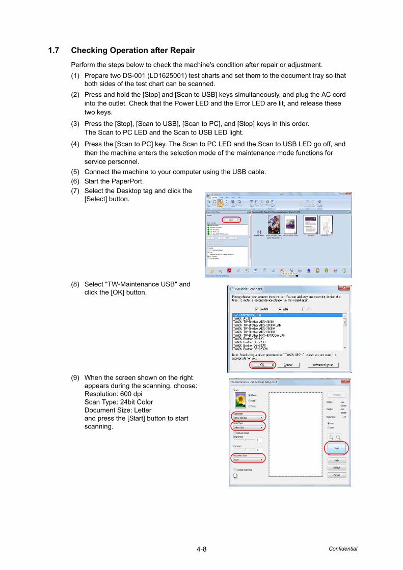
4-8 Confidential
1.7 Checking Operation after Repair
Perform the steps below to check the machine's condition after repair or adjustment.
(1) Prepare two DS-001 (LD1625001) test charts and set them to the document tray so that both sides of the test chart can be scanned.
(2) Press and hold the [Stop] and [Scan to USB] keys simultaneously, and plug the AC cord into the outlet. Check that the Power LED and the Error LED are lit, and release these two keys.
(3) Press the [Stop], [Scan to USB], [Scan to PC], and [Stop] keys in this order. The Scan to PC LED and the Scan to USB LED light.
(4) Press the [Scan to PC] key. The Scan to PC LED and the Scan to USB LED go off, and then the machine enters the selection mode of the maintenance mode functions for service personnel.
(5) Connect the machine to your computer using the USB cable.
(6) Start the PaperPort.
(7) Select the Desktop tag and click the [Select] button.
(8) Select "TW-Maintenance USB" and click the [OK] button.
(9) When the screen shown on the right appears during the scanning, choose:Resolution: 600 dpiScan Type: 24bit ColorDocument Size: Letterand press the [Start] button to start scanning.
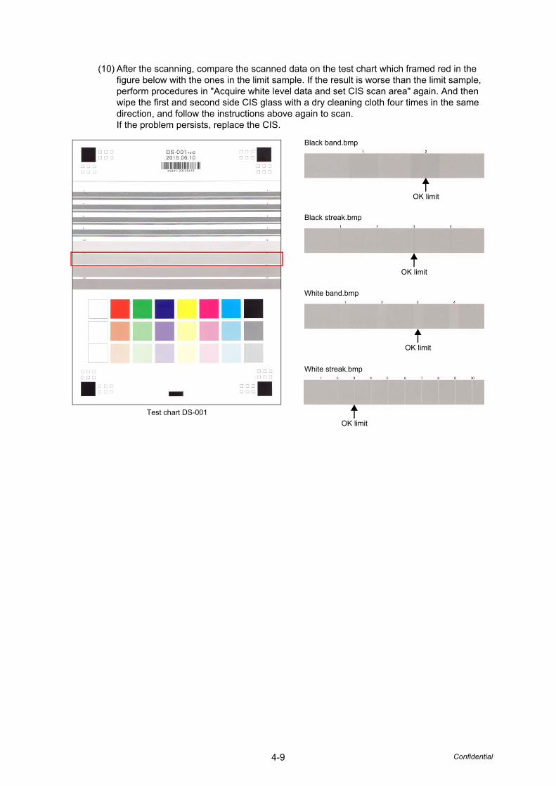
4-9 Confidential
(10) After the scanning, compare the scanned data on the test chart which framed red in the figure below with the ones in the limit sample. If the result is worse than the limit sample, perform procedures in "Acquire white level data and set CIS scan area" again. And then wipe the first and second side CIS glass with a dry cleaning cloth four times in the same direction, and follow the instructions above again to scan. If the problem persists, replace the CIS.
Test chart DS-001
Black band.bmp
Black streak.bmp
White band.bmp
White streak.bmp
OK limit
OK limit
OK limit
OK limit
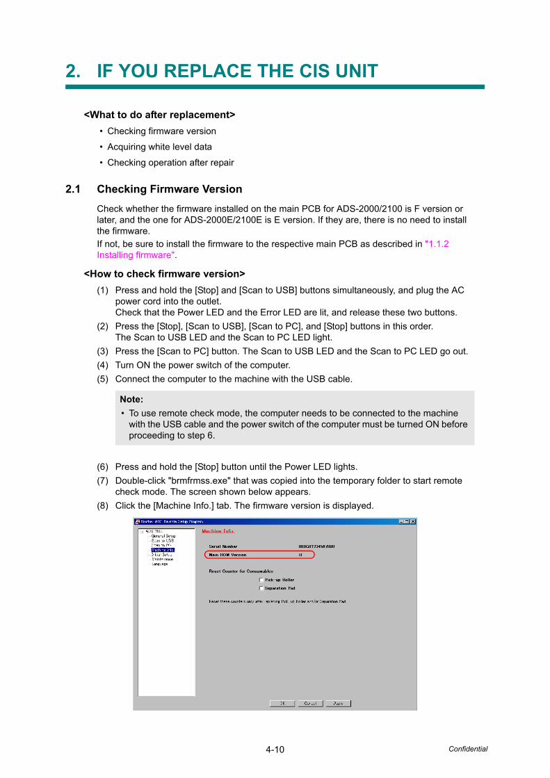
4-10 Confidential
2. IF YOU REPLACE THE CIS UNIT
<What to do after replacement>
• Checking firmware version
• Acquiring white level data
• Checking operation after repair
2.1 Checking Firmware Version
Check whether the firmware installed on the main PCB for ADS-2000/2100 is F version or later, and the one for ADS-2000E/2100E is E version. If they are, there is no need to install the firmware.
If not, be sure to install the firmware to the respective main PCB as described in "1.1.2 Installing firmware".
<How to check firmware version>
(1) Press and hold the [Stop] and [Scan to USB] buttons simultaneously, and plug the AC power cord into the outlet. Check that the Power LED and the Error LED are lit, and release these two buttons.
(2) Press the [Stop], [Scan to USB], [Scan to PC], and [Stop] buttons in this order. The Scan to USB LED and the Scan to PC LED light.
(3) Press the [Scan to PC] button. The Scan to USB LED and the Scan to PC LED go out.
(4) Turn ON the power switch of the computer.
(5) Connect the computer to the machine with the USB cable.
(6) Press and hold the [Stop] button until the Power LED lights.
(7) Double-click "brmfrmss.exe" that was copied into the temporary folder to start remote check mode. The screen shown below appears.
(8) Click the [Machine Info.] tab. The firmware version is displayed.
Note:
• To use remote check mode, the computer needs to be connected to the machine with the USB cable and the power switch of the computer must be turned ON before proceeding to step 6.
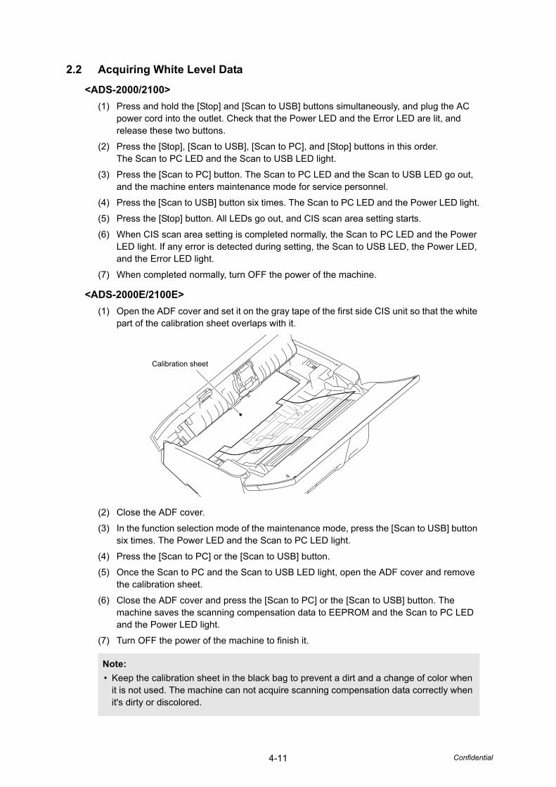
4-11 Confidential
2.2 Acquiring White Level Data
<ADS-2000/2100>
(1) Press and hold the [Stop] and [Scan to USB] buttons simultaneously, and plug the AC power cord into the outlet. Check that the Power LED and the Error LED are lit, and release these two buttons.
(2) Press the [Stop], [Scan to USB], [Scan to PC], and [Stop] buttons in this order. The Scan to PC LED and the Scan to USB LED light.
(3) Press the [Scan to PC] button. The Scan to PC LED and the Scan to USB LED go out, and the machine enters maintenance mode for service personnel.
(4) Press the [Scan to USB] button six times. The Scan to PC LED and the Power LED light.
(5) Press the [Stop] button. All LEDs go out, and CIS scan area setting starts.
(6) When CIS scan area setting is completed normally, the Scan to PC LED and the Power LED light. If any error is detected during setting, the Scan to USB LED, the Power LED, and the Error LED light.
(7) When completed normally, turn OFF the power of the machine.
<ADS-2000E/2100E>
(1) Open the ADF cover and set it on the gray tape of the first side CIS unit so that the white part of the calibration sheet overlaps with it.
(2) Close the ADF cover.
(3) In the function selection mode of the maintenance mode, press the [Scan to USB] button six times. The Power LED and the Scan to PC LED light.
(4) Press the [Scan to PC] or the [Scan to USB] button.
(5) Once the Scan to PC and the Scan to USB LED light, open the ADF cover and remove the calibration sheet.
(6) Close the ADF cover and press the [Scan to PC] or the [Scan to USB] button. The machine saves the scanning compensation data to EEPROM and the Scan to PC LED and the Power LED light.
(7) Turn OFF the power of the machine to finish it.
Note:
• Keep the calibration sheet in the black bag to prevent a dirt and a change of color when it is not used. The machine can not acquire scanning compensation data correctly when it's dirty or discolored.
Calibration sheet

4-12 Confidential
2.3 Checking Operation after Repair
Perform the steps below to check the machine's condition after repair or adjustment.
(1) Prepare two DS-001 (LD1625001) test charts and set them to the document tray so that both sides of the test chart can be scanned.
(2) Press and hold the [Stop] and [Scan to USB] keys simultaneously, and plug the AC cord into the outlet. Check that the Power LED and the Error LED are lit, and release these two keys.
(3) Press the [Stop], [Scan to USB], [Scan to PC], and [Stop] keys in this order. The Scan to PC LED and the Scan to USB LED light.
(4) Press the [Scan to PC] key. The Scan to PC LED and the Scan to USB LED go off, and then the machine enters the selection mode of the maintenance mode functions for service personnel.
(5) Connect the machine to your computer using the USB cable.
(6) Start the PaperPort.
(7) Select the Desktop tag and click the [Select] button.
(8) Select "TW-Maintenance USB" and click the [OK] button.
(9) When the screen shown on the right appears during the scanning, choose:Resolution: 600 dpiScan Type: 24bit ColorDocument Size: Letterand press the [Start] button to start scanning.

4-13 Confidential
(10) After the scanning, compare the scanned data on the test chart which framed red in the figure below with the ones in the limit sample. If the result is worse than the limit sample, perform procedures in "Acquire white level data and set CIS scan area" again. And then wipe the first and second side CIS glass with a dry cleaning cloth four times in the same direction, and follow the instructions above again to scan. If the problem persists, replace the CIS.
Test chart DS-001
Black band.bmp
Black streak.bmp
White band.bmp
White streak.bmp
OK limit
OK limit
OK limit
OK limit

4-14 Confidential
3. IF YOU REPLACE THE DOUBLE FEEDING SENSOR
<What to do after replacement>
• Setting double feeding sensor threshold
• Checking double feeding function
What you need to prepare
(1) Sheet for double feeding sensor threshold setting (LD6340001)
(2) Double feeding sensor threshold setting tool (BrADSmt1.exe)Copy this file into the temporary folder created on the C drive.
3.1 Setting Double Feeding Sensor Threshold
(1) Press and hold the [Stop] and [Scan to USB] buttons simultaneously, and plug the AC power cord into the outlet. Check that the Power LED and the Error LED are lit, and release these two buttons.
(2) Press the [Stop], [Scan to USB], [Scan to PC], and [Stop] buttons in this order. The Scan to USB LED and the Scan to PC LED light.
(3) Turn ON the power switch of the computer.
(4) Connect the computer to the machine with the USB cable.
(5) Double-click "BrADSmt1.exe" that was copied into the temporary folder to start it.
(6) Select the model name in the [Select model:] box, and click the [Start] button. The double feeding sensor threshold is set.
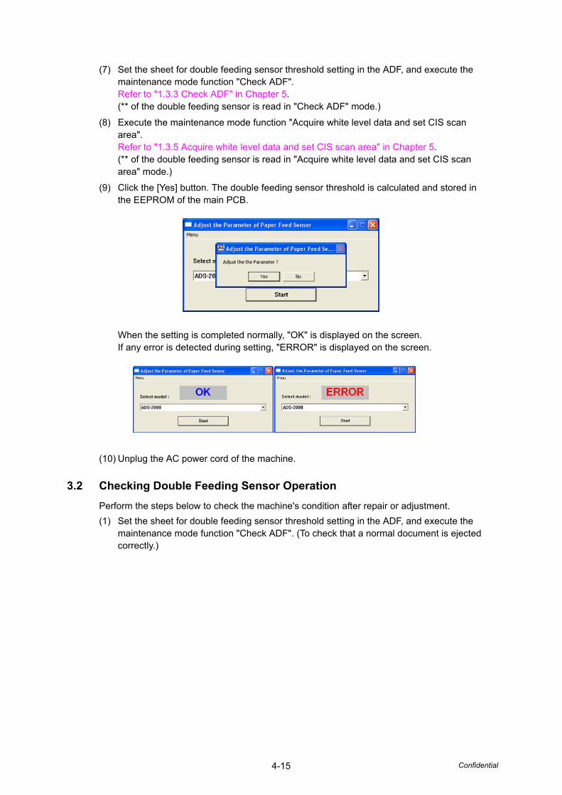
4-15 Confidential
(7) Set the sheet for double feeding sensor threshold setting in the ADF, and execute the maintenance mode function "Check ADF".Refer to "1.3.3 Check ADF" in Chapter 5.(** of the double feeding sensor is read in "Check ADF" mode.)
(8) Execute the maintenance mode function "Acquire white level data and set CIS scan area".Refer to "1.3.5 Acquire white level data and set CIS scan area" in Chapter 5.(** of the double feeding sensor is read in "Acquire white level data and set CIS scan area" mode.)
(9) Click the [Yes] button. The double feeding sensor threshold is calculated and stored in the EEPROM of the main PCB.
When the setting is completed normally, "OK" is displayed on the screen.If any error is detected during setting, "ERROR" is displayed on the screen.
(10) Unplug the AC power cord of the machine.
3.2 Checking Double Feeding Sensor Operation
Perform the steps below to check the machine's condition after repair or adjustment.
(1) Set the sheet for double feeding sensor threshold setting in the ADF, and execute the maintenance mode function "Check ADF". (To check that a normal document is ejected correctly.)

4-16 Confidential
4. IF YOU REPLACE THE PANEL ASSY
<What to do after replacement>
• Checking control panel operation
4.1 Acquiring White Level Data for Second Side CIS Unit
<ADS-2000/2100>
(1) Press and hold the [Stop] and [Scan to USB] buttons simultaneously, and plug the AC power cord into the outlet. Check that the Power LED and the Error LED are lit, and release these two buttons.
(2) Press the [Stop], [Scan to USB], [Scan to PC], and [Stop] buttons in this order. The Scan to PC LED and the Scan to USB LED light.
(3) Press the [Scan to PC] button. The Scan to PC LED and the Scan to USB LED go out, and the machine enters maintenance mode for service personnel.
(4) Press the [Scan to USB] button six times. The Scan to PC LED and the Power LED light.
(5) Press the [Stop] button. All LEDs go out, and CIS scan area setting starts.
(6) When CIS scan area setting is completed normally, the Scan to PC LED and the Power LED light. If any error is detected during setting, the Scan to USB LED, the Power LED, and the Error LED light.
(7) When completed normally, turn OFF the power of the machine.
<ADS-2000E/2100E>
(1) Open the ADF cover and set it on the gray tape of the first side CIS unit so that the white part of the calibration sheet overlaps with it.
(2) Close the ADF cover.
(3) In the function selection mode of the maintenance mode, press the [Scan to USB] button six times. The Power LED and the Scan to PC LED light.
(4) Press the [Scan to PC] or the [Scan to USB] button.
(5) Once the Scan to PC and the Scan to USB LED light, open the ADF cover and remove the calibration sheet.
(6) Close the ADF cover and press the [Scan to PC] or the [Scan to USB] button. The machine saves the scanning compensation data to EEPROM and the Scan to PC LED and the Power LED light.
(7) Turn OFF the power of the machine to finish it.
Note:
• Keep the calibration sheet in the black bag to prevent a dirt and a change of color when it is not used. The machine can not acquire scanning compensation data correctly when it's dirty or discolored.
Calibration sheet
4-17 Confidential
4.2 Checking Operation after Repair
Perform the steps below to check the machine's condition after repair or adjustment.
(1) Prepare some test chart sheets (Test chart TC-027, Color test chart CTC-001, Contrast chart TC-023), and set them in the document tray.
(2) Insert the USB flash memory into the USB terminal.
(3) Press the [Scan to USB] button to begin scanning.Check that sheets are picked up and fed one sheet at a time.When an error occurs, refer to the troubleshooting procedure to repair the machine.
(4) Turn over the test chart and perform procedure (1) to (3) to check the other side.
(5) When scanning is completed, remove the USB flash memory and connect it to the computer. Check the scanned data on the computer. Check that the image quality on the first side and second side are the same. If there is any difference, acquire the white level data again. If the image is distorted, refer to the troubleshooting procedure to repair the machine again.

4-18 Confidential
5. IF YOU REPLACE THE PICK-UP ROLLER / SEPARATION PAD
<What to do after replacement>
• Resetting pick-up roller / separation pad counters
5.1 Resetting Pick-up Roller / Separation Pad Counters
Refer to the User's Guide to reset the pick-up roller and separation pad counters.

Confidential
CHAPTER 5SERVICE FUNCTIONS

Confidential
CHAPTER 5 SERVICE FUNCTIONS
This chapter describes the maintenance mode which is exclusively designed for the purpose of checking the settings and adjustments using the buttons on the control panel. This chapter also covers not-disclosed-to-users function menus, which activate settings and functions or reset the parts life.
CONTENTS1. MAINTENANCE MODE ................................................................................................5-1
1.1 How to Enter Maintenance Mode ..........................................................................5-1
1.1.1 Method of entering end-user accessible maintenance mode.....................5-1
1.1.2 Method of entering maintenance mode for service personnel ...................5-1
1.2 List of Maintenance Mode Functions.....................................................................5-2
1.3 Details of Maintenance Mode Functions ...............................................................5-3
1.3.1 Change USB No. return value (End-user accessible maintenance mode only) .........................................5-3
1.3.2 Initialize user setting...................................................................................5-3
1.3.3 Check ADF.................................................................................................5-3
1.3.4 Check sensor operation .............................................................................5-4
1.3.5 Acquire white level data and set CIS scan area.........................................5-4

5-1 Confidential
1. MAINTENANCE MODE
Maintenance mode is exclusively designed for checking and setting the machine using the buttons on the control panel.
1.1 How to Enter Maintenance Mode
1.1.1 Method of entering end-user accessible maintenance mode
The maintenance mode functions should only be accessed by service personnel. However, end users are allowed to use some of these functions under the guidance of service personnel over the phone. End users can only use the functions shaded in the table on the next page.
<Operating Procedure>
(1) Press and hold the [Scan to PC] and [Scan to USB] buttons simultaneously, and plug the AC power cord into the outlet. Check that all LEDs are lit, and release these two buttons.
(2) Press the [Scan to PC] button. All LEDs go out and the machine enters function number selection mode of the end-user accessible maintenance mode.
1.1.2 Method of entering maintenance mode for service personnel
<Operating Procedure>
(1) Press and hold the [Stop] and [Scan to USB] buttons simultaneously, and plug the AC power cord into the outlet. Check that the Power LED and the Error LED are lit, and release these two buttons.
(2) Press the [Stop], [Scan to USB], [Scan to PC], and [Stop] buttons in this order. The Scan to PC LED and the Scan to USB LED light.
(3) Press the [Scan to PC] button. The Scan to LED and the Scan to USB LED go out and the machine enters function number selection mode of the maintenance mode for service personnel.
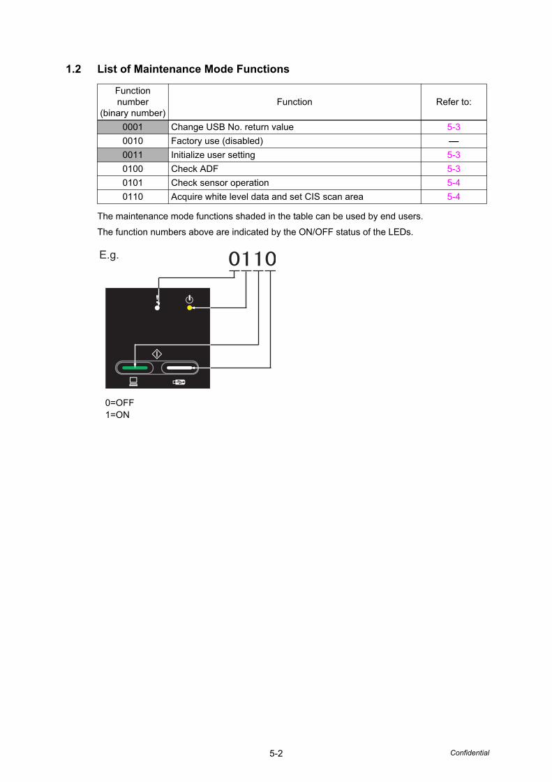
5-2 Confidential
1.2 List of Maintenance Mode Functions
The maintenance mode functions shaded in the table can be used by end users.
The function numbers above are indicated by the ON/OFF status of the LEDs.
0=OFF1=ON
Function number
(binary number)Function Refer to:
0001 Change USB No. return value 5-3
0010 Factory use (disabled) -
0011 Initialize user setting 5-3
0100 Check ADF 5-3
0101 Check sensor operation 5-4
0110 Acquire white level data and set CIS scan area 5-4
E.g.
5-3 Confidential
1.3 Details of Maintenance Mode Functions
1.3.1 Change USB No. return value (End-user accessible maintenance mode only)
<Function>
When the operating system (OS) installed on the computer is Windows Vista®, and the machine is connected to this computer using USB2.0FULL, the OS may not be able to obtain the USB device serial number depending on the computer and the USB device. If the serial number cannot be obtained, the number of devices increases each time the device is connected to the computer. To avoid this problem, set this function to "USBNo.=ON" and fix the USB No. return value to "0".
<Operation Procedure>
(1) In function number selection mode of end-user accessible maintenance mode, press the [Scan to USB] button once. The Scan to USB LED lights.
(2) Press the [Stop] button.When the Power LED lights for one second, it means that "return serial number of machine" is set.When the Error LED lights for one second, it means that "return 0" is set.
(3) When setting is completed, the machine returns to the ready state.
1.3.2 Initialize user setting
<Function>
This function is used to initialize the setting values for operation parameters, user switches, and others registered in the EEPROM.
<Operation Procedure>
(1) In function number selection mode of maintenance mode, press the [Scan to USB] button three times. The Scan to PC LED and the Scan to USB LED light.
(2) Press the [Stop] button. The EEPROM is initialized, and the machine returns to the ready state.
1.3.3 Check ADF
<Function>
This function is used to check whether the document set in the ADF is fed correctly while counting the number of documents.
<Operation Procedure>
(1) In function number selection mode of maintenance mode, set the document in the ADF.
(2) Press the [Scan to USB] button four times. The Power LED lights.
(3) Press the [Stop] button. The document is picked up and fed one sheet at a time, and the Scan to USB LED lights each time.Check that the number of times the LED lights matches the number of documents set.
(4) Press the [Stop] button. The machine returns to function number selection mode.
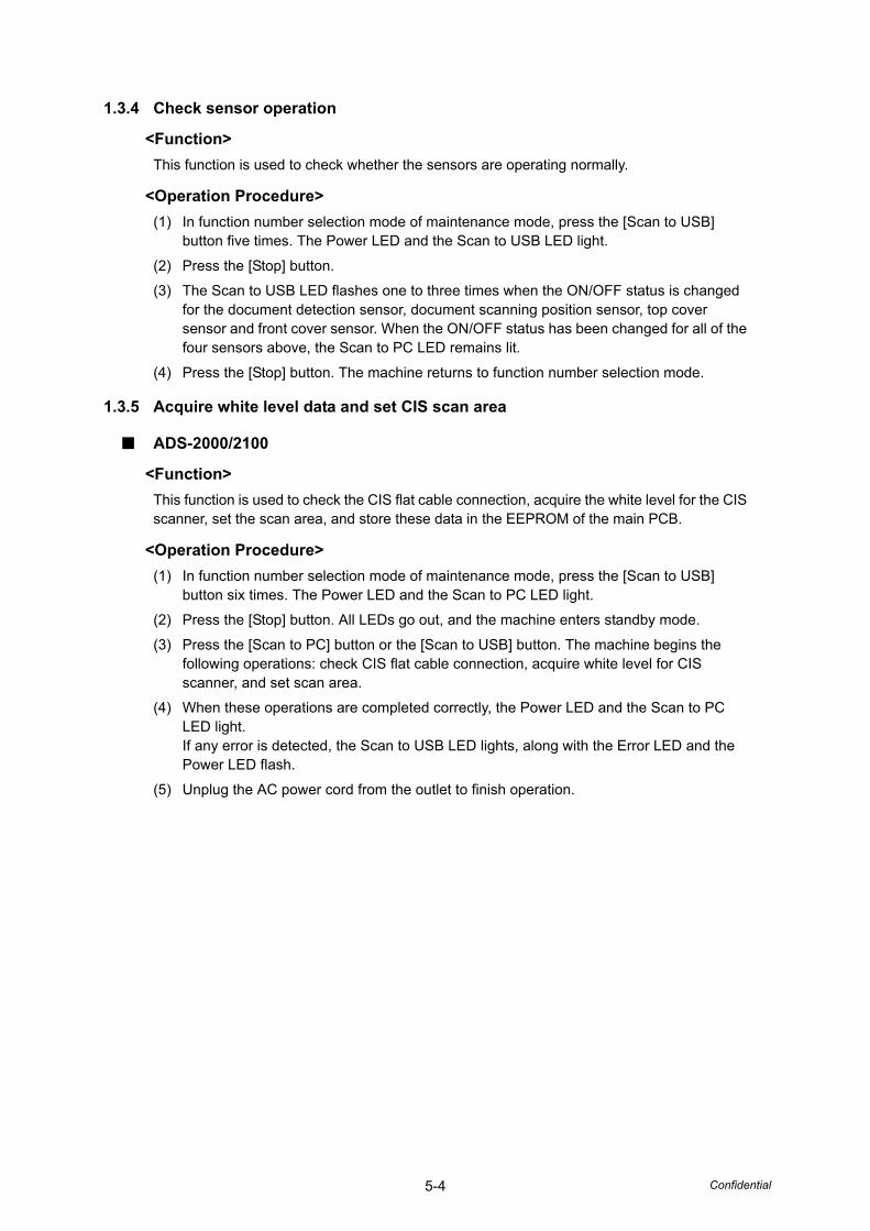
5-4 Confidential
1.3.4 Check sensor operation
<Function>
This function is used to check whether the sensors are operating normally.
<Operation Procedure>
(1) In function number selection mode of maintenance mode, press the [Scan to USB] button five times. The Power LED and the Scan to USB LED light.
(2) Press the [Stop] button.
(3) The Scan to USB LED flashes one to three times when the ON/OFF status is changed for the document detection sensor, document scanning position sensor, top cover sensor and front cover sensor. When the ON/OFF status has been changed for all of the four sensors above, the Scan to PC LED remains lit.
(4) Press the [Stop] button. The machine returns to function number selection mode.
1.3.5 Acquire white level data and set CIS scan area
■ ADS-2000/2100
<Function>
This function is used to check the CIS flat cable connection, acquire the white level for the CIS scanner, set the scan area, and store these data in the EEPROM of the main PCB.
<Operation Procedure>
(1) In function number selection mode of maintenance mode, press the [Scan to USB] button six times. The Power LED and the Scan to PC LED light.
(2) Press the [Stop] button. All LEDs go out, and the machine enters standby mode.
(3) Press the [Scan to PC] button or the [Scan to USB] button. The machine begins the following operations: check CIS flat cable connection, acquire white level for CIS scanner, and set scan area.
(4) When these operations are completed correctly, the Power LED and the Scan to PC LED light. If any error is detected, the Scan to USB LED lights, along with the Error LED and the Power LED flash.
(5) Unplug the AC power cord from the outlet to finish operation.
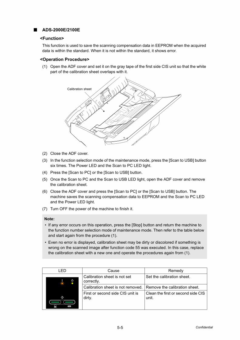
5-5 Confidential
■ ADS-2000E/2100E
<Function>
This function is used to save the scanning compensation data in EEPROM when the acquired data is within the standard. When it is not within the standard, it shows error.
<Operation Procedure>
(1) Open the ADF cover and set it on the gray tape of the first side CIS unit so that the white part of the calibration sheet overlaps with it.
(2) Close the ADF cover.
(3) In the function selection mode of the maintenance mode, press the [Scan to USB] button six times. The Power LED and the Scan to PC LED light.
(4) Press the [Scan to PC] or the [Scan to USB] button.
(5) Once the Scan to PC and the Scan to USB LED light, open the ADF cover and remove the calibration sheet.
(6) Close the ADF cover and press the [Scan to PC] or the [Scan to USB] button. The machine saves the scanning compensation data to EEPROM and the Scan to PC LED and the Power LED light.
(7) Turn OFF the power of the machine to finish it.
Note:
• If any error occurs on this operation, press the [Stop] button and return the machine to the function number selection mode of maintenance mode. Then refer to the table below and start again from the procedure (1).
• Even no error is displayed, calibration sheet may be dirty or discolored if something is wrong on the scanned image after function code 55 was executed. In this case, replace the calibration sheet with a new one and operate the procedures again from (1).
LED Cause Remedy
Calibration sheet is not set correctly.
Set the calibration sheet.
Calibration sheet is not removed. Remove the calibration sheet.
First or second side CIS unit is dirty.
Clean the first or second side CIS unit.
Calibration sheet
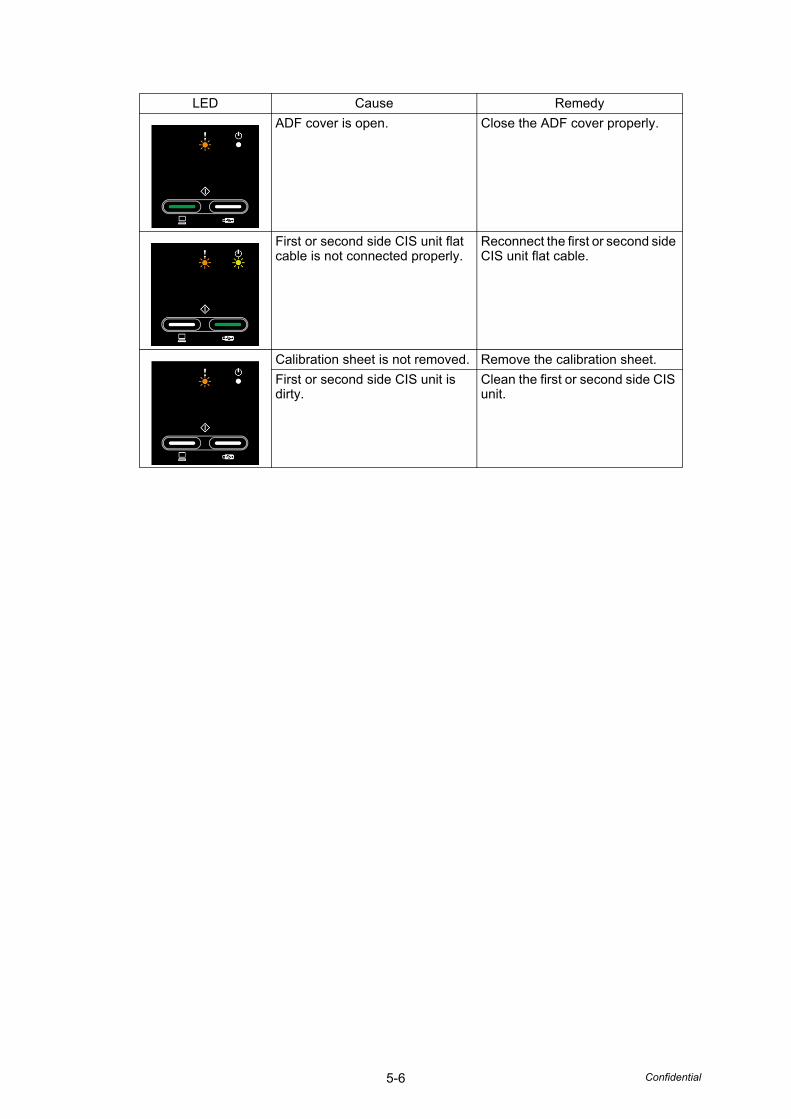
5-6 Confidential
ADF cover is open. Close the ADF cover properly.
First or second side CIS unit flat cable is not connected properly.
Reconnect the first or second side CIS unit flat cable.
Calibration sheet is not removed. Remove the calibration sheet.
First or second side CIS unit is dirty.
Clean the first or second side CIS unit.
LED Cause Remedy

Confidential
CHAPTER 6WIRING DIAGRAM

Confidential
CHAPTER 6 WIRING DIAGRAM
This chapter provides the wiring diagram for the connections of the PCBs.
CONTENTS1. WIRING DIAGRAM .......................................................................................................6-1
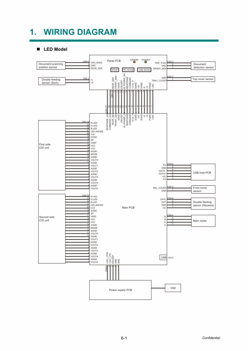
6-1 Confidential
1. WIRING DIAGRAM
LED Model
Documentdetection sensor
Document scanningposition sensor
CN3-6
CN5-2
CN4-4
54321
1
321
CN3-21
CN5-321
CN8-4321
CN15
CN2-24232221201918171615141312111098
54321
76
CN1-24232221201918171615141312111098
54321
76
CN
7-17 1516 14 13 12
CN
9-5 34 2 1
11 10 9 8 7 6 5 4 3 2 1
CN
1-15 14 13 12 11 10 9 8 7 6 5 4 3 2 1
CN4-321
CN6-21
USB SCANPC SCAN
ERROR POWER
GNDTRAY_COVER
GNDFRONT_SEN
VDD_FLED
RE
AR
_SE
NFR
ON
T_S
EN
SG
ND
DS
LEE
PM
_PO
WE
R_E
NR
ES
PO
NS
EC
OM
MA
ND
+3.3
V_P
SG
ND
SG
ND
-S +S+5V
PG
ND
+24V
GNDREAR_SEN
VDD_RLED
+S-S
USB
FG
FG
GND
GND+5V
OUTCNTL
A
BB
A
PNL_COVER
GNDDATA-DATA+
+5V
VOUT5
VOUT4
VOUT3
VOUT2
VOUT1
VOUT0
AGND
AGND
AGND
AGND
AGND
AGND
AGND
SPAGNDCLKLED-ANODEB-LEDG-LEDR-LED
VCCVCCVREF
MODE
VOUT5
VOUT4
VOUT3
VOUT2
VOUT1
VOUT0
AGND
AGND
AGND
AGND
AGND
AGND
AGND
SPAGNDCLKLED-ANODEB-LEDG-LEDR-LED
VCCVCCVREF
MODE
RE
SP
ON
SE
_SU
BC
OM
MA
ND
_SU
BR
EA
R_S
EN
FRO
NT_
SE
NS
GN
DD
SLE
EP
M_P
OW
ER
_EN
RE
SP
ON
SE
CO
MM
AN
D+3
.3V
_PS
GN
D
SG
ND
-S +S+5V
PG
ND
+24V
+24V
_LP
S+2
4V_L
PS
2
DS
LEE
P
GN
DG
ND
Double feedingsensor (Sent)
First sideCIS unit
Second sideCIS unit
Main PCB
USB host PCB
Front coversensor
Main motor
Power supply PCBInlet
Double feeding sensor (Receive)
Panel PCB
Top cover sensor
STOP

Confidential
CHAPTER 7PERIODICAL MAINTENANCE

Confidential
CHAPTER 7 PERIODICAL MAINTENANCE
CONTENTS
1. PERIODICAL MAINTENANCE PARTS ........................................................................7-1

7-1 Confidential
1. PERIODICAL MAINTENANCE PARTS
There are no parts that must be replaced periodically.

Confidential
APPENDIX 1SERIAL NUMBERING SYSTEM
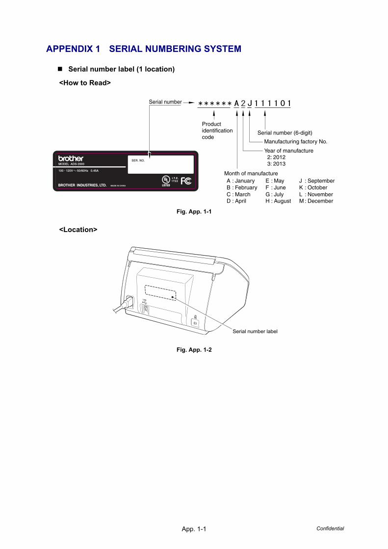
ConfidentialApp. 1-1
APPENDIX 1 SERIAL NUMBERING SYSTEM
Serial number label (1 location)
<How to Read>
Fig. App. 1-1
<Location>
Fig. App. 1-2
Serial number
Serial number (6-digit)
Manufacturing factory No.
A : JanuaryB : FebruaryC : March D : April
Year of manufacture 2: 2012 3: 2013
Month of manufacture
Productidentificationcode
E : MayF : JuneG : July H : August
J : SeptemberK : OctoberL : November M : December
Serial number label

Confidential
APPENDIX 2DELETING USER SETTING INFORMATION
This appendix provides instructions on how to delete user setting information recorded in the machine.

ConfidentialApp. 2-1
APPENDIX 2 DELETING USER SETTING INFORMATION
Initializes setting values registered in EEPROM including operation parameter and user switch.
<Operation Procedure>
(1) In function number selection mode of maintenance mode, press the [Scan to USB] button three times. The Scan to PC LED and the Scan to USB LED light.
(2) Press the [Stop] button. The EEPROM is initialized, and the machine returns to the ready state.

Confidential
APPENDIX 3INSTALLING MAINTENANCE DRIVER

ConfidentialApp. 3-1
APPENDIX 3 INSTALLING MAINTENANCE DRIVER
To identify multiple terminals connected to the computer via USB, the computer needs to configure the corresponding number of virtual USB devices using a driver or software. If you connect multiple machines to your computer, the same number of virtual USB devices will be automatically configured on your computer. To prevent an unlimited number of virtual USB devices from being configured, use the unique driver installation procedure described below to enable your computer to identify multiple terminals via one single virtual USB device.
<Operating Procedure>
(1) Check that the AC power cord of the machine is unplugged. When the machine is connected to the computer, disconnect the USB cable.
(2) Turn ON the power switch of the computer.
(3) Press and hold the [Stop] and [Scan to PC] buttons simultaneously, and plug the AC power cord into the outlet. Check that the Power LED and the Error LED are lit, and release these two buttons.
(4) Press the [Scan to PC], [Stop] buttons in this order. The Scan to PC LED lights.
(5) Double-click "maintenance.exe" for the maintenance driver stored in the temporary folder to execute it.
(6) The Device Driver Installation Wizard startup window appears. Click [Next].
(7) The WHQL alert window appears three times. Click [Continue Anyway] on each window to continue installation.
(8) The Device Driver Installation Wizard completion window appears. Click [Finish].
(9) Connect the machine to your computer using the USB cable.
(10) The Found New Hardware Wizard startup window appears. Select "Install the software automatically" and click [Next].
(11) The WHQL alert window appears. Click [Continue Anyway].
(12) When the driver is installed successfully, the Found New Hardware Wizard completion window appears. Click [Finish].
(13) Repeat steps (10) to (12) three times to complete the unique driver installation procedure.
(14) Disconnect the USB cable, and unplug the AC power cord of the machine.