
Brocade G620 Hardware Installation GuideInstallation and Initial Configuration.....17 Shipping...
89
HARDWARE INSTALLATION GUIDE Brocade G620 Hardware Installation Guide 53-1003990-13 21 September 2018
Transcript of Brocade G620 Hardware Installation GuideInstallation and Initial Configuration.....17 Shipping...

HARDWARE INSTALLATION GUIDE
Brocade G620 Hardware Installation Guide
53-1003990-1321 September 2018

Copyright © 2018 Brocade Communications Systems LLC. All Rights Reserved. Brocade and the stylized B logo are among the trademarks of BrocadeCommunications Systems LLC. Broadcom, the pulse logo, and Connecting everything are among the trademarks of Broadcom. The term "Broadcom"refers to Broadcom Inc. and/or its subsidiaries.
Brocade, a Broadcom Inc. Company, reserves the right to make changes without further notice to any products or data herein to improve reliability,function, or design. Information furnished by Brocade is believed to be accurate and reliable. However, Brocade does not assume any liability arising out ofthe application or use of this information, nor the application or use of any product or circuit described herein, neither does it convey any license under itspatent rights nor the rights of others.
The product described by this document may contain open source software covered by the GNU General Public License or other open source licenseagreements. To find out which open source software is included in Brocade products, view the licensing terms applicable to the open source software, andobtain a copy of the programming source code, please visit https://www.broadcom.com/support/fibre-channel-networking/tools/oscd.
Brocade G620 Hardware Installation Guide2 53-1003990-13

ContentsIntroduction.......................................................................................................................................................................................................................... 6
About This Document..............................................................................................................................................................................................................................6Supported Hardware and Software.................................................................................................................................................................................................... 6What Is New in This Document............................................................................................................................................................................................................6Notes, Cautions, and Warnings............................................................................................................................................................................................................ 7Resources......................................................................................................................................................................................................................................................8Contacting Brocade Technical Support............................................................................................................................................................................................ 8Document Feedback................................................................................................................................................................................................................................8
Device Overview..................................................................................................................................................................................................................9Hardware Features.....................................................................................................................................................................................................................................9License Options.......................................................................................................................................................................................................................................10Port-Side View.........................................................................................................................................................................................................................................10Nonport-Side View.................................................................................................................................................................................................................................11Device Management Options............................................................................................................................................................................................................12
Preparing for the Installation..........................................................................................................................................................................................13Safety Precautions..................................................................................................................................................................................................................................13
General Precautions......................................................................................................................................................................................................................13ESD Precautions............................................................................................................................................................................................................................14Power Precautions........................................................................................................................................................................................................................ 14Lifting and Weight-Related Precautions.............................................................................................................................................................................. 15Laser Precautions..........................................................................................................................................................................................................................16
Facility Requirements............................................................................................................................................................................................................................ 16Quick Installation Checklist................................................................................................................................................................................................................. 16
Pre-Installation Tasks................................................................................................................................................................................................................... 16Installation and Initial Configuration........................................................................................................................................................................................17
Shipping Carton Contents...................................................................................................................................................................................................................18
Mounting the Device........................................................................................................................................................................................................19Mounting options.................................................................................................................................................................................................................................... 19Precautions Specific to Mounting.................................................................................................................................................................................................... 19Standalone installation .........................................................................................................................................................................................................................20Installing the Universal Four-Post Rack Kit (XBR-R000296).............................................................................................................................................20
Time and Items Required........................................................................................................................................................................................................... 21Parts List............................................................................................................................................................................................................................................21Flush-Front Mounting..................................................................................................................................................................................................................23Flush-Rear (Recessed) Mounting........................................................................................................................................................................................... 28
Installing the Universal Two-Post Rack Kit (XBR-R000294)..............................................................................................................................................33Time and Items Required........................................................................................................................................................................................................... 34Parts List............................................................................................................................................................................................................................................34Flush-Front Mounting..................................................................................................................................................................................................................35Mid-Mounting................................................................................................................................................................................................................................. 39
Initial Setup and Verification.......................................................................................................................................................................................... 44Items Required......................................................................................................................................................................................................................................... 44Providing Power to the Device.......................................................................................................................................................................................................... 44Establishing a First-Time Serial Connection................................................................................................................................................................................45
Brocade G620 Hardware Installation Guide53-1003990-13 3

Configuring the IP Address.................................................................................................................................................................................................................46Using DHCP to Set the IP Address....................................................................................................................................................................................... 46Setting a Static IP Address........................................................................................................................................................................................................ 46
Setting the Date and Time...................................................................................................................................................................................................................46Setting the Time Zone................................................................................................................................................................................................................. 47Synchronizing the Local Time with an External Source.................................................................................................................................................48
Customizing the Chassis Name and Switch Name..................................................................................................................................................................48Establishing an Ethernet Connection..............................................................................................................................................................................................48Setting the Domain ID...........................................................................................................................................................................................................................49Verifying correct operation.................................................................................................................................................................................................................. 49Backing Up the Configuration........................................................................................................................................................................................................... 51Powering Down the Device.................................................................................................................................................................................................................51
Installing Transceivers and Cables................................................................................................................................................................................52Time and Items Required.....................................................................................................................................................................................................................52Precautions Specific to Transceivers and Cables...................................................................................................................................................................... 53Cleaning the Fiber-Optic Connectors............................................................................................................................................................................................ 53Managing Cables.................................................................................................................................................................................................................................... 53Replacing an SFP+ Transceiver........................................................................................................................................................................................................ 54Installing a QSFP Transceiver............................................................................................................................................................................................................56Replacing a QSFP Transceiver..........................................................................................................................................................................................................57Verifying the Operation of New Transceivers..............................................................................................................................................................................58
Monitoring the Device..................................................................................................................................................................................................... 60Interpreting Port-Side LEDs...............................................................................................................................................................................................................60
System Power LED...................................................................................................................................................................................................................... 60System Status LED.......................................................................................................................................................................................................................61Management Port LED ..............................................................................................................................................................................................................61FC Port Status LED......................................................................................................................................................................................................................61QSFP port status LED................................................................................................................................................................................................................62
Interpreting Nonport-side LEDs.......................................................................................................................................................................................................63Power Supply and Fan Assembly Status LED..................................................................................................................................................................63
Interpreting POST Results.................................................................................................................................................................................................................. 64Interpreting BOOT Results................................................................................................................................................................................................................. 64Running Diagnostic Tests....................................................................................................................................................................................................................65
Power Supply and Fan Assembly..................................................................................................................................................................................66Power Supply and Fan Assembly Overview............................................................................................................................................................................... 66Precautions Specific to the Power Supply and Fan Assemblies.........................................................................................................................................67Identifying the airflow direction..........................................................................................................................................................................................................67Power Supply and Fan Assembly Status LED........................................................................................................................................................................... 68Power Supply and Fan Assembly Unit Fault Indicators..........................................................................................................................................................68Power Supply and Fan Assembly Task Guide............................................................................................................................................................................69
Installing an Additional Power Supply and Fan Assembly (Hot-Install).................................................................................................................. 69Replacing a Power Supply and Fan Assembly (Hot-Swap).........................................................................................................................................69Replacing Both Power Supply and Fan Assemblies (Cold-Swap)............................................................................................................................ 69
Time and Items Required.....................................................................................................................................................................................................................70Recording Power Supply and Fan Assembly Critical Information......................................................................................................................................70Removing a power supply and fan assembly............................................................................................................................................................................. 70Inserting a new power supply and fan assembly.......................................................................................................................................................................71Verifying the Operation of the Power Supply and Fan Assemblies...................................................................................................................................73
Brocade G620 Hardware Installation Guide4 53-1003990-13

Brocade G620 Technical Specifications.....................................................................................................................................................................74System specifications............................................................................................................................................................................................................................74Fibre Channel............................................................................................................................................................................................................................................74Other............................................................................................................................................................................................................................................................ 75LEDs.............................................................................................................................................................................................................................................................75Other............................................................................................................................................................................................................................................................ 75Weight and physical dimensions...................................................................................................................................................................................................... 75Environmental requirements.............................................................................................................................................................................................................. 75Power supply specifications (per PSU).......................................................................................................................................................................................... 76Power consumption (typical configuration).................................................................................................................................................................................. 76Power consumption (maximum configuration)...........................................................................................................................................................................77Power consumption (idle configuration)........................................................................................................................................................................................ 77Data port specifications (Fibre Channel)........................................................................................................................................................................................77Fibre Channel data transmission ranges.......................................................................................................................................................................................77Serial port specifications (pinout RJ-45).......................................................................................................................................................................................78Serial port specifications (protocol)..................................................................................................................................................................................................78Memory specifications..........................................................................................................................................................................................................................79Regulatory Compliance (EMC).......................................................................................................................................................................................................... 79Regulatory Compliance (Safety)........................................................................................................................................................................................................79Regulatory Compliance (Environmental).......................................................................................................................................................................................79
Regulatory Statements....................................................................................................................................................................................................81BSMI Statement (Taiwan).................................................................................................................................................................................................................... 81Canadian Requirements.......................................................................................................................................................................................................................81CE Statement............................................................................................................................................................................................................................................81China CCC Statement...........................................................................................................................................................................................................................82China ROHS............................................................................................................................................................................................................................................. 82FCC Warning (U.S. Only)......................................................................................................................................................................................................................82Germany Statement...............................................................................................................................................................................................................................83KCC Statement (Republic of Korea).................................................................................................................................................................................................83VCCI Statement.......................................................................................................................................................................................................................................83Taiwan ROHS certification.................................................................................................................................................................................................................. 84
Cautions and Danger Notices........................................................................................................................................................................................ 85Danger Notices........................................................................................................................................................................................................................................ 85
General Dangers............................................................................................................................................................................................................................ 85Electrical Dangers..........................................................................................................................................................................................................................85Dangers Related to Equipment Weight................................................................................................................................................................................ 87Laser Dangers.................................................................................................................................................................................................................................87
Cautions...................................................................................................................................................................................................................................................... 87General Cautions............................................................................................................................................................................................................................88Electrical Cautions.........................................................................................................................................................................................................................88
Brocade G620 Hardware Installation Guide53-1003990-13 5

Introduction• About This Document.........................................................................................................................................................................................6• Supported Hardware and Software...............................................................................................................................................................6• What Is New in This Document...................................................................................................................................................................... 6• Notes, Cautions, and Warnings.......................................................................................................................................................................7• Resources................................................................................................................................................................................................................ 8• Contacting Brocade Technical Support.......................................................................................................................................................8• Document Feedback...........................................................................................................................................................................................8
About This DocumentThis hardware installation guide contains procedures and safety requirements for installing the Brocade G620 Switch into a rack system
or as a standalone device. Also provided are steps to initially con igure the switch for operation, verify and monitor operation, replace switch ield-replaceable units (FRUs), and install transceivers and cables. Complete technical speci ications for the switch are also included.
Supported Hardware and SoftwareThe Brocade G620 FC switch is introduced in Fabric OS 8.0.0 software release. The following tables list the power supply and fan assemblies, and rack mount kits supported on this device.
TABLE 1 Power Supply and Fan AssembliesPart Number Description Introduced (OS) Currently Supported
(OS)
XBR-G250WPSAC-F 250W AC power supply with nonport-side exhaustairflow
Fabric OS 8.0.0 Yes
XBR-G250WPSAC-R 250W AC power supply with nonport-side intakeairflow
Fabric OS 8.0.0 Yes
TABLE 2 Rack Mount Kits
Part Number Description
XBR-R000294 Universal two-post mid-mount or flush-mount rack kit
XBR-R000296 Universal four-post fixed rack mount kit
What Is New in This DocumentThe following changes are made to this document from its previous version.
• The following corrections were made to provide information on the supported AC power supply only.
– Removed rows describing DC power supplies in "Power supply and fan assemblies" table in Supported Hardware andSoftware on page 6.
– Removed precautions for DC power supplies in Power Precautions on page 14.
Brocade G620 Hardware Installation Guide6 53-1003990-13
– Removed figure of the nonport-side view with DC power supply and fan assembly units from Nonport-Side View on page11.
– Removed figure showing nonport-side LEDs with DC power supplies from Interpreting Nonport-side LEDs on page 63.– Removed figure showing DC power supply and fan assembly and bullets detailing DC power supply function from Power
Supply and Fan Assembly Overview on page 66.– Removed precautions for DC power supplies in Precautions Specific to the Power Supply and Fan Assemblies on page
67.– Removed illustration showing DC power supply and fan assembly from Removing a power supply and fan assembly on
page 70.– Removed illustration showing DC power supply installation from Inserting a new power supply and fan assembly on page
71.– In "Power supply specifications (per PSU)" in the Brocade G620 Technical Specifications on page 74, removed rows
providing DC power supply specifications.– For "Power consumption (typical configuration)" in the Brocade G620 Technical Specifications on page 74, changed "48
VDC input column values to "Not supported".– For "Power consumption (maximum configuration)" in the Brocade G620 Technical Specifications on page 74, changed
"48 VDC input column values to "Not supported".– For "Power consumption (idle configuration)" in the Brocade G620 Technical Specifications on page 74, changed "48
VDC input column" values to "Not supported".– Removed cautions for DC power supplies from Cautions and Danger Notices on page 85.
• The following corrections were made to stress the integration of fans into the fan and power supply assemblies.
– Revised figure showing nonport-side view with AC power supply and fan assembly units to remove callouts for individualfans 1-3 in Nonport-Side View on page 11.
– Revised figure showing AC power supply and fan assembly to remove call outs for individual fans 1-3 in Power Supplyand Fan Assembly Overview on page 66 as fans are integrated in assembly.
– In "System Specifications" in the Brocade G620 Technical Specifications on page 74, changed "Fans" description to"Three fans integrated into power supply and fan assemblies".
Notes, Cautions, and WarningsNotes, cautions, and warning statements may be used in this document.
NOTEA Note provides a tip, guidance, or advice, emphasizes important information, or provides a reference to related information.
CAUTIONA Caution statement alerts you to situations that can be potentially hazardous to you or cause damage to hardware,firmware, software, or data.
DANGERA Danger statement indicates conditions or situations that can be potentially lethal or extremely hazardous to you. Safetylabels are also attached directly to products to warn of these conditions or situations.
Notes, Cautions, and Warnings
Brocade G620 Hardware Installation Guide53-1003990-13 7

ResourcesVisit the Brocade website to locate related documentation for your product and additional Brocade resources.
White papers, data sheets, and the most recent versions of Brocade software and hardware manuals are available at https://www.broadcom.com/products/fibre-channel-networking/. Product documentation for all supported releases is available to registeredusers at MyBrocade.
Click the Support tab and select Document Library to access product documentation on MyBrocade or https://www.broadcom.com/products/fibre-channel-networking/. You can locate documentation by product or by operating system.
Release notes are bundled with software downloads on MyBrocade. Links to software downloads are available on the MyBrocade landingpage and in the Document Library.
Contacting Brocade Technical SupportFor product support information and the latest information on contacting the Technical Assistance Center, go to https://www.broadcom.com/support/fibre-channel-networking/. If you have purchased Brocade product support directly from Brocade, useone of the following methods to contact the Brocade Technical Assistance Center 24x7.
Online Telephone
For nonurgent issues, the preferred method is to go to MyBrocade(my.brocade.com) and then go to one of the following sites:
• My Cases
• Software Downloads
• Licensing tools
• Knowledge Base
Required for Severity 1-Critical and Severity 2-High issues:
• North America: 1-800-752-8061 (Toll-free)
• International: 1-669-234-1001 (Not toll-free)
Toll-free numbers are available in many countries and are listed at https://www.broadcom.com/support/fibre-channel-networking/.
If you purchased Brocade product support from a Brocade OEM/solution provider, contact your OEM/solution provider for all yourproduct support needs.
• OEM/solution providers are trained and certified by Brocade to support Brocade products.
• Brocade provides backline support for issues that cannot be resolved by the OEM/solution provider.
• Brocade Supplemental Support augments your existing OEM support contract, providing direct access to Brocade expertise.For more information, contact Brocade or your OEM.
• For questions regarding service levels and response times, contact your OEM/solution provider.
Document FeedbackQuality is our first concern. We have made every effort to ensure the accuracy and completeness of this document. However, if you findan error or an omission or if you think that a topic needs further development, we want to hear from you. Send your feedback to [email protected]. Provide the publication title, publication number, topic heading, page number, and as much detail aspossible.
Resources
Brocade G620 Hardware Installation Guide8 53-1003990-13

Device Overview• Hardware Features............................................................................................................................................................................................... 9• License Options................................................................................................................................................................................................. 10• Port-Side View....................................................................................................................................................................................................10• Nonport-Side View........................................................................................................................................................................................... 11• Device Management Options.......................................................................................................................................................................12
Hardware FeaturesThe Brocade G620 offers the following features and capabilities:
• Up to 48 auto-sensing ports supporting high-performance 32Gb/s SFP+ ports technology in a single domain.
• Up to four 128Gb/s (4 x 32Gb/s) QSFP ports to connect to the QSFP ports of another Brocade G620 device.
• Dynamic Ports on Demand (Dynamic-POD) scaling from a base configuration of 24 ports to 64 ports (two 12-port SFP+PODs and one 16-port QSFP POD).
• 4, 8, 16, and 32Gb/s auto-sensing Fibre Channel switch and router ports.
– A 32Gb/s optical transceiver can auto-negotiate to 32Gb/s, 16Gb/s, or 8Gb/s.– A 16Gb/s optical transceiver can auto-negotiate to 16Gb/s, 8Gb/s, or 4Gb/s.
NOTEThe port speed is determined by the maximum speed supported by the optical transceiver at the other end of the link.
• 10Gb/s manually set capability on FC ports (requires the optional 10-Gigabit FCIP/Fibre Channel license).
– 10Gb/s performance is enabled by 10Gb/s SFP+ transceivers.– Ports can be configured for 10Gb/s for metro connectivity.
• Universal ports self-configure as a E_Ports, F_Ports, M_Ports, or D_Ports. EX_Ports can be activated on a per-port basis withthe optional Integrated Routing license.
– A Diagnostic Port (D_Port) provides diagnostics, troubleshooting, and verification services for the physical media.
• In-flight 64Gb/s data compression and encryption provides efficient link utilization and security. The following table lists thenumber of ports that can be enabled with compression and encryption.
Port Speed Encryption Only Compression Only Compression and Encryption
32Gb/s Not supported 4 ports Not supported
16Gb/s Not supported 4 ports Not supported
10Gb/s Not supported 4 ports Not supported
8Gb/s Not supported 4 ports Not supported
4Gb/s Not supported 4 ports Not supported
• Dynamic buffer sharing
• Support for port-side exhaust or nonport-side exhaust airflow for cooling.
• Hardware-enabled input and output (I/O) latency statistics collection.
• Hardware-enabled VM support.
• Brocade small form-factor pluggable plus (SFP+) optical transceivers support any combination of Short Wavelength (SWL),Long Wavelength (LWL) or Extended Long Wavelength (ELWL) optical media among the switch ports.
Brocade G620 Hardware Installation Guide53-1003990-13 9

• Extended distance Fibre Channel to support long distance native FC connectivity.
• 10Gb/s Fibre Channel integration on any selected port provides DWDM metro connectivity on the same switch.
• Port-to-port latency is minimized to 900 nanoseconds (including FEC) by using cut-through frame switching at 32Gb/s.
• High performance T1022 processor with two cores operating at 1.2 GHz delivers high performance, scalability, and advancedFabric Vision functionality.
• One 1000/100/10 Mb/s RJ45 connector Ethernet port for management connection. In conjunction with EZSwitchSetup, thisport supports switch IP address discovery and configuration, eliminating the need to attach a serial cable to configure the switchIP address.
• One RS-232 3-wire (Tx, Rx, and Gnd) universal asynchronous receiver/transmitter (UART) serial port to BMC with RJ-45connector for debugging initial switch setup (if not using EZSwitchSetup) and factory default restoration. Integral LEDs remainunlit at all times.
• One internal e-USB module provides 2 GB of persistent storage, increased serviceability, and error logging functionality byfacilitating easier firmware upgrades and downloads of the system log files.
• One external USB connector.
• Two hot-swappable redundant integrated power supply and fan assembly field-replaceable units.
• 48 hot-pluggable SFP+ optical transceiver slots and 4 hot-pluggable QSFP optical transceiver slots.
• 64 bicolor (green/amber) LEDs to indicate the status for each port.
• One green LED to indicate valid system power.
• One bicolor (green/amber) LED to indicate the system status.
• Two Ethernet LEDs: one bicolor (green/amber) LED to indicate link at 1000/100/10 Mb/s and one green LED to indicateactivity.
• SEEPROM for switch identification.
• Real-time power monitoring.
• Real-time voltage monitoring.
• Real-time fan monitoring including airflow direction.
• Real-time digital thermometers for temperature monitoring.
• Real-time clock (RTC) with battery.
License OptionsThe Brocade G620 uses a capacity-based Ports on Demand (POD) license method. An Integrated Routing (IR) license is required toenable EX_Port on this device. Refer to the Brocade Fabric OS Software Licensing Guide for more details.
Port-Side ViewThe following illustration shows the port-side view of the Brocade G620 Fibre Channel switch.
License Options
Brocade G620 Hardware Installation Guide10 53-1003990-13

FIGURE 1 Port-Side View
1. System Status LED
2. System Power LED
3. UART RJ-45 Serial Console Port
4. SFP+ FC (four upper and four lower) Ports 0-7
5. SFP+ FC (four upper and four lower) Ports 8-15
6. SFP+ FC (four upper and four lower) Ports 16-23
7. SFP+ FC (four upper and four lower) Ports 24-31
8. SFP+ FC (four upper and four lower) Ports 32-39
9. SFP+ FC (four upper and four lower) Ports 40-47
10. QSFP Port 0 (FC Ports 48-51)
11. QSFP Port 2 (FC Ports 56-59)
12. QSFP Port 3 (FC Ports 60-63)
13. QSFP Port 1 (FC Ports 52-55)
14. SFP+ (lower) Port 14 Status LED
15. SFP+ (upper) Port 10 Status LED
16. 1000/100/10 Mbps RJ-45 Ethernet Management Port
17. USB Port
NOTEAll the ports are connected to a single ASIC.
Nonport-Side ViewThe following illustration shows the nonport-side view of the Brocade G620 FC switch.
FIGURE 2 Nonport-Side View with AC Power Supply and Fan Assembly Units
1. Ground Sticker
2. Ground Cable Connector
3. Power Supply and Fan Assembly 2
4. Power Supply and Fan Assembly 1
5. Captive Screw
6. Handle
7. Power Supply and Fan Assembly Status LED
8. Power-On Switch
9. Power Supply Receptacle
Nonport-Side View
Brocade G620 Hardware Installation Guide53-1003990-13 11

Device Management OptionsYou can use the management functions built into the device to monitor the fabric topology, port status, physical status, and otherinformation to help you analyze switch performance and to accelerate system debugging. The device automatically performs a power-onself-test (POST) each time it is turned on. A RASlog message is generated for any detected startup errors.
You can manage the device using any of the management options listed in the following table.
TABLE 3 Management Options for the Device
Management Tool Out-of-Band Support Reference Documents
Command line interface (CLI)
Up to two admin sessions and four usersessions simultaneously.
Ethernet or serial connection Brocade Fabric OS Administration Guide
Brocade Fabric OS Command Reference
Brocade EZSwitchSetup
EZSwitchSetup helps to complete the basicconfiguration for single-switch setup.
Ethernet or serial connection EZSwitchSetup Software Installation Guide
EZSwitchSetup Administrator's Guide
Brocade Web Tools Ethernet or serial connection Brocade Web Tools Administration Guide
Standard SNMP applications Ethernet or serial connection Fabric OS MIB Reference
Management Server Ethernet or serial connection Brocade Fabric OS Administration Guide
Brocade Fabric OS Command Reference
Brocade Network Advisor (BNA)
BNA must be purchased separately.
Ethernet or serial connection Brocade Network Advisor documentation set
Device Management Options
Brocade G620 Hardware Installation Guide12 53-1003990-13

Preparing for the Installation• Safety Precautions............................................................................................................................................................................................ 13• Facility Requirements.......................................................................................................................................................................................16• Quick Installation Checklist............................................................................................................................................................................16• Shipping Carton Contents..............................................................................................................................................................................18
Safety PrecautionsWhen using this product, observe all danger, caution, and attention notices in this manual. The safety notices are accompanied bysymbols that represent the severity of the safety condition.
See "Cautions and Danger Notices" at the end of this guide for translations of safety notices for this product.
General PrecautionsDANGERThe procedures in this manual are for qualified service personnel.
DANGERBefore beginning the installation, see the precautions in “Power precautions.”
DANGERBe careful not to accidently insert your fingers into the fan tray while removing it from the chassis. The fan may still bespinning at a high speed.
CAUTIONChanges or modifications made to this device that are not expressly approved by the party responsible for compliancecould void the user's authority to operate the equipment.
CAUTIONDisassembling any part of the power supply and fan assembly voids the warranty and regulatory certifications. There are nouser-serviceable parts inside the power supply and fan assembly.
CAUTIONMake sure the airflow around the front, and back of the device is not restricted.
CAUTIONEnsure that the airflow direction of the power supply unit matches that of the installed fan tray. The power supplies and fantrays are clearly labeled with either a green arrow with an "E", or an orange arrow with an "I."
CAUTIONNever leave tools inside the chassis.
CAUTIONTo protect the serial port from damage, keep the cover on the port when not in use.
Brocade G620 Hardware Installation Guide53-1003990-13 13
CAUTIONIf you do not install a module or a power supply in a slot, you must keep the slot filler panel in place. If you run the chassiswith an uncovered slot, the system will overheat.
CAUTIONDo not install the device in an environment where the operating ambient temperature might exceed 40°C (104°F).
ESD PrecautionsDANGERFor safety reasons, the ESD wrist strap should contain a series 1 megaohm resistor.
CAUTIONBefore plugging a cable into any port, be sure to discharge the voltage stored on the cable by touching the electricalcontacts to ground surface.
CAUTIONStatic electricity can damage the chassis and other electronic devices. To avoid damage, keep static-sensitive devices intheir static-protective packages until you are ready to install them.
NOTEWear a wrist grounding strap connected to the chassis ground (if the device is plugged in) or to a bench ground.
Power PrecautionsDANGERMake sure that the power source circuits are properly grounded, then use the power cord supplied with the device toconnect it to the power source.
DANGERIf the installation requires a different power cord than the one supplied with the device, make sure you use a power corddisplaying the mark of the safety agency that defines the regulations for power cords in your country. The mark is yourassurance that the power cord can be used safely with the device.
DANGERThis device might have more than one power cord. To reduce the risk of electric shock, disconnect all power cords beforeservicing.
DANGERRemove both power cords before servicing.
DANGERDisconnect the power cord from all power sources to completely remove power from the device.
DANGERTo avoid high voltage shock, do not open the device while the power is on.
Safety Precautions
Brocade G620 Hardware Installation Guide14 53-1003990-13

NOTEBatteries used for RTC/NVRAM backup are not located in operator-access areas. There is a risk of explosion if a battery isreplaced by an incorrect type. Dispose of used components with batteries according to local ordinance and regulations.
CAUTIONUse a separate branch circuit for each power cord, which provides redundancy in case one of the circuits fails.
CAUTIONEnsure that the device does not overload the power circuits, wiring, and over-current protection. To determine thepossibility of overloading the supply circuits, add the ampere (amp) ratings of all devices installed on the same circuit as thedevice. Compare this total with the rating limit for the circuit. The maximum ampere ratings are usually printed on thedevices near the input power connectors.
CAUTIONThe power supply switch must be in the off position when you insert the power supply into the chassis. Damage to theswitch can result if a live power supply is installed.
CAUTIONCarefully follow the mechanical guides on each side of the power supply slot and make sure the power supply is properlyinserted in the guides. Never insert the power supply upside down.
NOTEDevice control processors and management modules may contain batteries for RTC or NVRAM backup. Dispose ofcomponents containing batteries as required by local ordinances and regulations.
Lifting and Weight-Related PrecautionsDANGERUse safe lifting practices when moving the product.
DANGERMount the devices you install in a rack as low as possible. Place the heaviest device at the bottom and progressively placelighter devices above.
DANGERMake sure the rack housing the device is adequately secured to prevent it from becoming unstable or falling over.
CAUTIONDo not use the port cover tabs to lift the module. They are not designed to support the weight of the module, which can falland be damaged.
CAUTIONTo prevent damage to the chassis and components, never attempt to lift the chassis using the fan or power supply handles.These handles were not designed to support the weight of the chassis.
Safety Precautions
Brocade G620 Hardware Installation Guide53-1003990-13 15

Laser PrecautionsDANGERAll fiber-optic interfaces use Class 1 lasers.
DANGERUse only optical transceivers that are qualified by Brocade Communications Systems LLC and comply with the FDAClass 1 radiation performance requirements defined in 21 CFR Subchapter I, and with IEC 60825 and EN60825. Opticalproducts that do not comply with these standards might emit light that is hazardous to the eyes.
Facility RequirementsBefore installing the device, be sure that the following facilities requirements are met.
TABLE 4 Facility Requirements
Type Requirements
Electrical • Adequate supply circuit, line fusing, and wire size, as specified by the electrical rating on the switchnameplate
• Circuit protected by a circuit breaker and grounded in accordance with local electrical codesSee the technical specifications at the end of this guide for complete power supply specifications.
Thermal • A minimum airflow of 79.8 cubic meters/hour (47 cubic ft/min.) available in the immediate vicinity ofthe switch
NOTEAlthough this airflow may exceed the airflow maximum listed in the device technicalspecifications, the additional airflow is recommended to pressurize the inlet (cool isle) sideof rack installations relative to the exhaust side to minimize recirculation of hot air back tothe inlet side.
• Ambient air temperature not exceeding 40°C (104°F) while the switch is operating
Rack (when rack-mounted) • One rack unit (1U) in a 48.3 cm (19 in.) rack
• All equipment in the rack grounded through a reliable branch circuit connection
• Additional weight of the switch not to exceed the rack’s weight limits
• Rack secured to ensure stability in case of unexpected movement
Quick Installation ChecklistThis checklist provides a high-level overview of the basic installation process from the planning stage to the point where the devicecomes online and is ready to be deployed. Completing all the tasks in the suggested order ensures successful installation. Brocaderecommends that you print this checklist and take it to the installation site.
Pre-Installation TasksReview all installation requirements ahead of time as part of your site preparation. Careful planning and site preparation ensures seamlessinstallation, especially when installing multiple devices.
Facility Requirements
Brocade G620 Hardware Installation Guide16 53-1003990-13
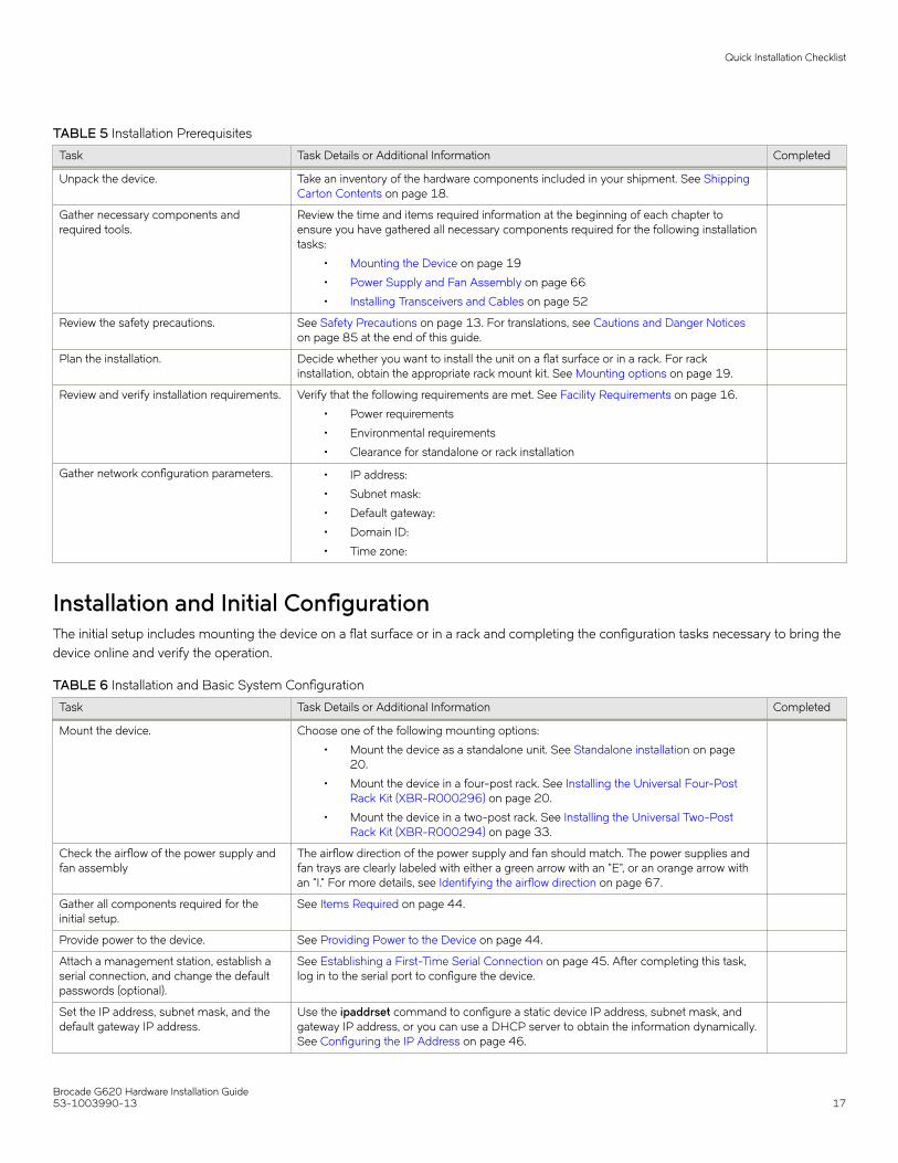
TABLE 5 Installation Prerequisites
Task Task Details or Additional Information Completed
Unpack the device. Take an inventory of the hardware components included in your shipment. See ShippingCarton Contents on page 18.
Gather necessary components andrequired tools.
Review the time and items required information at the beginning of each chapter toensure you have gathered all necessary components required for the following installationtasks:
• Mounting the Device on page 19
• Power Supply and Fan Assembly on page 66
• Installing Transceivers and Cables on page 52
Review the safety precautions. See Safety Precautions on page 13. For translations, see Cautions and Danger Noticeson page 85 at the end of this guide.
Plan the installation. Decide whether you want to install the unit on a flat surface or in a rack. For rackinstallation, obtain the appropriate rack mount kit. See Mounting options on page 19.
Review and verify installation requirements. Verify that the following requirements are met. See Facility Requirements on page 16.
• Power requirements
• Environmental requirements
• Clearance for standalone or rack installation
Gather network configuration parameters. • IP address:
• Subnet mask:
• Default gateway:
• Domain ID:
• Time zone:
Installation and Initial ConfigurationThe initial setup includes mounting the device on a flat surface or in a rack and completing the configuration tasks necessary to bring thedevice online and verify the operation.
TABLE 6 Installation and Basic System Configuration
Task Task Details or Additional Information Completed
Mount the device. Choose one of the following mounting options:
• Mount the device as a standalone unit. See Standalone installation on page20.
• Mount the device in a four-post rack. See Installing the Universal Four-PostRack Kit (XBR-R000296) on page 20.
• Mount the device in a two-post rack. See Installing the Universal Two-PostRack Kit (XBR-R000294) on page 33.
Check the airflow of the power supply andfan assembly
The airflow direction of the power supply and fan should match. The power supplies andfan trays are clearly labeled with either a green arrow with an "E", or an orange arrow withan "I." For more details, see Identifying the airflow direction on page 67.
Gather all components required for theinitial setup.
See Items Required on page 44.
Provide power to the device. See Providing Power to the Device on page 44.
Attach a management station, establish aserial connection, and change the defaultpasswords (optional).
See Establishing a First-Time Serial Connection on page 45. After completing this task,log in to the serial port to configure the device.
Set the IP address, subnet mask, and thedefault gateway IP address.
Use the ipaddrset command to configure a static device IP address, subnet mask, andgateway IP address, or you can use a DHCP server to obtain the information dynamically.See Configuring the IP Address on page 46.
Quick Installation Checklist
Brocade G620 Hardware Installation Guide53-1003990-13 17

TABLE 6 Installation and Basic System Configuration (continued)
Task Task Details or Additional Information Completed
Set the date and time. • Use the date command to display and set the date and time.
• Use the tstimezone command to display and set the time zone.
• Use the tsclockserver command to synchronize the time with an external NTPserver.
See Setting the Date and Time on page 46 for more information.
Customize the switch name and chassisname.
• Use the swicthname command to change the default switch name.
• Use the chassisname command to change the default chassis name.See Customizing the Chassis Name and Switch Name on page 48 for moreinformation.
Establish an Ethernet connection. By establishing an Ethernet connection, you can complete the device configuration usinga serial session, Telnet, or management application, such as Brocade Network Advisor.See Establishing an Ethernet Connection on page 48.
Optional: Configure the DNS service. Use the dnsconfig command to create DNS server entries. Refer to the Brocade FabricOS Administration Guide.
Optional: Customize the domain ID. Use the configure command to change the domain ID (default ID is 1). See Setting theDomain ID on page 49 for more information.
Verify that the device operates correctly. • Check the LEDs to verify operation of functional parts. See Interpreting Port-Side LEDs on page 60 and Interpreting Nonport-side LEDs on page 63.
• The following commands can be useful to establish an operational baseline forthe device. Refer to the Brocade Fabric OS Command Reference for moreinformation on these commands.
– psshow– fanshow– tempshow– historyshow– errdump
Back up the configuration. Use the interactive configupload command to back up the configuration. See Verifyingcorrect operation on page 49 for more information.
Optional: Power off the devices. Enter the shutdown command and wait for the device to power down, and then unplugthe power cords. See Powering Down the Device on page 51 for more information.
Shipping Carton ContentsWhen unpacking the device, verify that the contents of the shipping carton are complete. Save the shipping carton and packaging in theevent you need to return the shipment.
• The Brocade switch
• An accessory kit containing the following items:
– A serial cable– Two 1.82-m (6-ft) power cords– Download Instructions for Fibre Channel Networking Software and Documents
• Inner foam
Shipping Carton Contents
Brocade G620 Hardware Installation Guide18 53-1003990-13

Mounting the Device• Mounting options...............................................................................................................................................................................................19• Precautions Specific to Mounting...............................................................................................................................................................19• Standalone installation ....................................................................................................................................................................................20• Installing the Universal Four-Post Rack Kit (XBR-R000296)........................................................................................................20• Installing the Universal Two-Post Rack Kit (XBR-R000294).........................................................................................................33
Mounting optionsYou can install the device in several ways:
• As a standalone unit on a flat surface, for example, a table top. Use the rubber feet included with the shipment to secure thedevice on the surface. No other equipment is required for desktop installation.
• In a four-post EIA rack: You will need a Universal Four-Post Rack Kit (XBR-R000296) to install devices in EIA racks that arebetween L-13.7 to 81.28 cm deep (L-5.0 to 32.0 in.), where L is the chassis depth.
• In a two-post Telco rack: You will need a Universal Two-Post Rack Kit (XBR-R000294) to install 1U and 2U devices in a two-post telecommunications (Telco) rack.
NOTEReview the Safety Precautions before mounting the device.
Precautions Specific to MountingThe following precautions apply to mounting the device.
DANGERUse safe lifting practices when moving the product.
DANGERMount the devices you install in a rack as low as possible. Place the heaviest device at the bottom and progressively placelighter devices above.
CAUTIONMake sure the airflow around the front, and back of the device is not restricted.
CAUTIONNever leave tools inside the chassis.
CAUTIONDo not use the port cover tabs to lift the module. They are not designed to support the weight of the module, which can falland be damaged.
CAUTIONTo prevent damage to the chassis and components, never attempt to lift the chassis using the fan or power supply handles.These handles were not designed to support the weight of the chassis.
Brocade G620 Hardware Installation Guide53-1003990-13 19

Standalone installationComplete the following steps to install the device as a standalone unit on a table.
1. Unpack the device and verify the items listed under Shipping Carton Contents on page 18 are present and undamaged.
2. Apply the adhesive rubber feet to the underside of the device. The rubber feet help prevent the device from sliding off thesupporting surface.
a) Clean the indentations at each corner of the bottom of the device to ensure that they are free of dust or other debris thatmight lessen the adhesion of the feet.
b) With the adhesive side against the chassis, place one rubber foot in each indentation and press into place.
3. Place the device on a sturdy flat surface.
4. Provide power to the device as described in Providing Power to the Device on page 44.
NOTEDo not connect the device to the network until the IP address is set correctly. For instructions on how to set the IPaddress, refer to Configuring the IP Address on page 46.
Installing the Universal Four-Post Rack Kit (XBR-R000296)Use the following instructions to install 1U and 2U devices in EIA racks that are from L-12.7 to 81.28 cm (L-5.0 to 32.0 in.) deep,where L is the chassis depth, using the Universal Four-Post Rack Kit (XBR-R000296).
You can mount the device in a four-post rack in two ways:
• With the port side flush with the front posts.
• With the nonport side flush with the rear posts in a recessed position. A recessed position allows a more gradual bend in thefiber-optic cables connected to the switch and less interference in the aisle at the front of the rack.
TABLE 7 Space Requirements
Chassis with Port-SideSide Vents
Notes Chassis Depth Minimum Rack Depth Maximum Rack Depth
No Applicable to port-side and nonport-side flushmounts.
L L-12.7 cm (L-5 in.) 81.28 cm (32 in.)
Yes Applicable to port-side flush mounts. L L-12.7 cm (L-5 in.) 81.28 cm (32 in.)
Yes Applicable to nonport-side flush mounts. L L 81.28 cm (32 in.)
Note that if the chassis depth (L) is less than 40.64 cm (16 in.), the chassis will not fit into a rack with a maximum depth of 81.28 cm(32 in.) using the universal four-post rack kit. The maximum rack depth for a chassis less than 40.64 cm (16 in.) is 81.28 cm (32 in.)minus the difference between the chassis depth and 40.64 cm (16 in.). For example, a chassis with a depth (L) of 35.56 cm (14 in.) is5.08 cm (2 in.) smaller than 40.64 cm (16 in.), so it will install into a rack with a maximum depth of 81.28 cm (32 in.) – 5.08 cm (2 in.) =76.2 cm (30 in.).
Observe the following when mounting the device:
• Two people are required to install the device in a rack. One person holds the device, while the other screws in the front and rearbrackets.
Standalone installation
Brocade G620 Hardware Installation Guide20 53-1003990-13

• Before mounting your device, review any specific installation and facility requirements in the hardware installation guide for thedevice.
• Hardware devices illustrated in these procedures are for reference only and may not depict the device that you are installing intothe rack.
Time and Items RequiredAllow 15 to 30 minutes to complete the installation.
The following items are required to install the device using the Universal Four-Post Rack Kit:
• #2 Phillips torque screwdriver
• 1/4-inch slotted-blade torque screwdriver
Parts ListThe following parts are provided with the 1U, 1.5U, and 2U Universal Four Post Rack Kit (XBR-R000296).
Installing the Universal Four-Post Rack Kit (XBR-R000296)
Brocade G620 Hardware Installation Guide53-1003990-13 21

FIGURE 3 Universal Four-Post Rack Kit Parts
1. Front brackets (2)
2. Extension brackets, medium (2)
3. Rear brackets, short (2)
4. Rear brackets, long (2)
5. Extension brackets, long (2)
6. Screw, 8-32 x 5/16-in., panhead Phillips (8)
7. Screw, 8-32 x 5/16-in., flathead Phillips (16)
8. Screw, 6-32 x 1/4-in., panhead Phillips (8)
9. Screw, 10-32 x 5/8-in., panhead Phillips (8)
10. Retainer nut, 10-32 (8)
Ensure that the items listed and illustrated are included in the kit. Note that not all parts may be used with certain installations dependingon the device type.
Installing the Universal Four-Post Rack Kit (XBR-R000296)
Brocade G620 Hardware Installation Guide22 53-1003990-13

CAUTIONUse the screws specified in the procedure. Using longer screws can damage the device.
Flush-Front MountingCAUTIONThe device must be turned off and disconnected from the fabric during this procedure.
NOTEThe illustrations in the rack installation procedures are for reference only and may not show the device that you are installing.
Complete the following tasks to install the device in a four-post rack.
1. Attaching the Front Brackets on page 23
2. Attaching the Bracket Extensions to the Device on page 24
3. Installing the Device in the Rack on page 25
4. Attaching the Rear Brackets to the Extensions on page 26
5. Attaching the Rear Brackets to the Rack Posts on page 27
Attaching the Front BracketsComplete the following steps to attach the front brackets to the device.
1. Position the right front bracket with the flat side against the right side of the device at the front of the device, as shown in Figure4.
2. Insert four 8-32 x 5/16-in. flathead screws through the vertically aligned holes in the bracket and then into the holes on theside of the device. Use the upper and lower screw holes, leaving the center holes empty.
3. Repeat Step 1 and Step 2 to attach the left front bracket to the left side of the device.
Installing the Universal Four-Post Rack Kit (XBR-R000296)
Brocade G620 Hardware Installation Guide53-1003990-13 23

4. Tighten all 8-32 x 5/16-in. screws to a torque of 15 in-lb (17 cm-kg).
FIGURE 4 Attaching the Front Brackets
1. Brocade Device
2. Front Brackets
3. Screws, 8-32 x 5/16-in., Flathead Phillips
Attaching the Bracket Extensions to the DeviceComplete the following steps to attach the extension brackets to the device. You can use medium and long extension brackets for thistask.
1. Select the proper length bracket extension for your rack depth.
2. Position the right bracket extension along the side of the device as shown in Figure 5.
3. Insert four 8-32 x 5/16-in. flathead screws through the vertically aligned holes in the bracket extension and then into the holeson the side of the device. Use the upper and lower screw holes, leaving the center holes empty.
4. Repeat Steps 2 and 3 to attach the left bracket extension to the left side of the device.
Installing the Universal Four-Post Rack Kit (XBR-R000296)
Brocade G620 Hardware Installation Guide24 53-1003990-13

5. Tighten all 8-32 x 5/16-in. screws to a torque of 15 in-lb (17 cm-kg).
FIGURE 5 Attaching the Bracket Extensions to the Device
1. Bracket Extension 2. Screws, 8-32 x 5/16-in., Flathead Phillips
Installing the Device in the RackComplete the following steps to install the device in the rack.
1. Position the device in the rack, as shown in Figure 6, providing temporary support under the device the rail kit is secured to therack.
2. Attach the right front bracket to the right front rack post using two 10-32 x 5/8-in. panhead screws and two retainer nuts. Usethe upper and lower holes in the bracket.
Installing the Universal Four-Post Rack Kit (XBR-R000296)
Brocade G620 Hardware Installation Guide53-1003990-13 25

3. Tighten all the 10-32 x 5/8-in. screws to a torque of 25 in-lb (29 cm-kg).
FIGURE 6 Positioning the Device in the Rack
1. Screws, 10-32 x 5/8-in., Panhead Phillips 2. Retainer Nuts, 10-32
Attaching the Rear Brackets to the ExtensionsComplete the following steps to attach the rear brackets to the extensions. You can use short and long rear brackets for this task. Choosethe correct bracket for the depth of your rack.
1. Select the proper length rear bracket for your rack depth.
2. Slide the right rear bracket onto the right bracket extension, as shown in the following figure.
3. Attach the brackets using four 6-32 x 1/4-in. panhead screws.
If possible, leave at least one empty vertical pair of holes between the screws for better support.
4. Repeat Step 2 and 3 to attach the left rear bracket to the left bracket extension.
Installing the Universal Four-Post Rack Kit (XBR-R000296)
Brocade G620 Hardware Installation Guide26 53-1003990-13

5. Adjust the brackets to the rack depth and tighten all 6-32 x 1/4-in. screws to a torque of 9 in-lb (10 cm-kg).
FIGURE 7 Attaching the Rear Brackets to the Extensions
1. Rear Brackets 2. Screws, 6-32 x 1/4-in., Panhead Phillips
Attaching the Rear Brackets to the Rack PostsComplete the following steps to attach the rear brackets to the rack posts.
1. Attach the right rear bracket to the right rear rack post using two 10-32 x 5/8-in. panhead screws and two retainer nuts, asshown in Figure 8. Use the upper and lower holes in the bracket.
2. Attach the left rear bracket to the left rear rack post using two 10-32 x 5/8-in. panhead screws and two retainer nuts. Use theupper and lower holes in the bracket.
Installing the Universal Four-Post Rack Kit (XBR-R000296)
Brocade G620 Hardware Installation Guide53-1003990-13 27

3. Tighten all 10-32 x 5/8-in. screws to a torque of 25 in-lb (29 cm-kg).
FIGURE 8 Attaching the Rear Brackets to the Rack Posts
1. Screws, 10-32 x 5/8-in., Panhead Phillips 2. Retainer Nuts, 10-32
Flush-Rear (Recessed) MountingThe flush-rear (recessed) mounting is similar to the flush-front mounting except that the brackets are reversed on the device.
CAUTIONThe device must be turned off and disconnected from the fabric during this procedure.
NOTEThe illustrations in the rack installation procedures show a 1U device, but the instructions are the same for a 2U device. Theillustrations in the rack installation procedures are for reference only and may not show the actual device.
Complete the following tasks to install the device in a four-post rack:
1. Attaching the Front Brackets to the Rear of the Device on page 29
2. Attaching the Bracket Extensions to the Front of the Device on page 29
3. Installing the Device in the Rack on page 30
4. Attaching the Rear Brackets to the Extensions at the Front of the Device on page 31
5. Attaching the Rear Brackets to the Front Rack Posts on page 33
Installing the Universal Four-Post Rack Kit (XBR-R000296)
Brocade G620 Hardware Installation Guide28 53-1003990-13
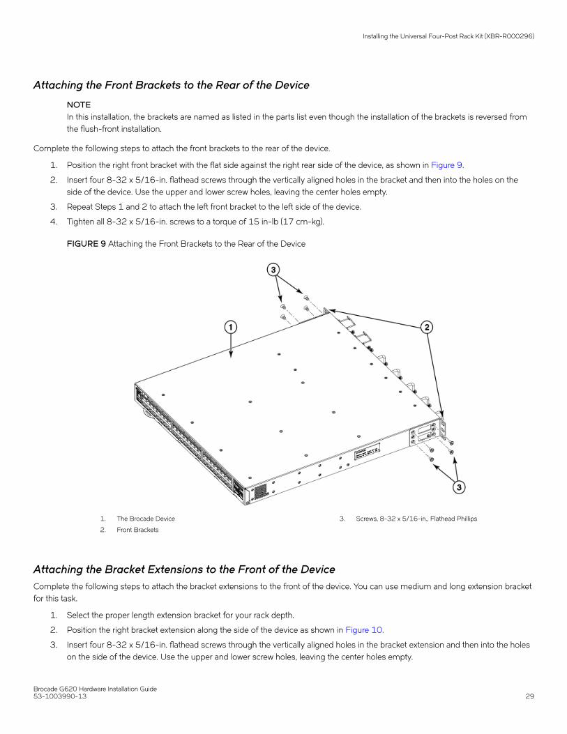
Attaching the Front Brackets to the Rear of the Device
NOTEIn this installation, the brackets are named as listed in the parts list even though the installation of the brackets is reversed fromthe flush-front installation.
Complete the following steps to attach the front brackets to the rear of the device.
1. Position the right front bracket with the flat side against the right rear side of the device, as shown in Figure 9.
2. Insert four 8-32 x 5/16-in. flathead screws through the vertically aligned holes in the bracket and then into the holes on theside of the device. Use the upper and lower screw holes, leaving the center holes empty.
3. Repeat Steps 1 and 2 to attach the left front bracket to the left side of the device.
4. Tighten all 8-32 x 5/16-in. screws to a torque of 15 in-lb (17 cm-kg).
FIGURE 9 Attaching the Front Brackets to the Rear of the Device
1. The Brocade Device
2. Front Brackets
3. Screws, 8-32 x 5/16-in., Flathead Phillips
Attaching the Bracket Extensions to the Front of the DeviceComplete the following steps to attach the bracket extensions to the front of the device. You can use medium and long extension bracketfor this task.
1. Select the proper length extension bracket for your rack depth.
2. Position the right bracket extension along the side of the device as shown in Figure 10.
3. Insert four 8-32 x 5/16-in. flathead screws through the vertically aligned holes in the bracket extension and then into the holeson the side of the device. Use the upper and lower screw holes, leaving the center holes empty.
Installing the Universal Four-Post Rack Kit (XBR-R000296)
Brocade G620 Hardware Installation Guide53-1003990-13 29

4. Repeat Steps 2 and 3 to attach the left front bracket extension to the left side of the device.
5. Tighten all the 8-32 x 5/16-in. screws to a torque of 15 in-lb (17 cm-kg).
FIGURE 10 Attaching the Bracket Extensions to the Device
1. Extension Brackets 2. Screws, 8-32 x 5/16-in., Flathead Phillips
Installing the Device in the RackComplete the following steps to install the device in the rack.
1. Position the device in the rack, as shown in Figure 11, providing temporary support under the device until the rail kit is securedto the rack.
2. Attach the right front bracket to the right rear rack post using two 10-32 x 5/8-in. panhead screws and two retainer nuts. Usethe upper and lower holes in the bracket.
Installing the Universal Four-Post Rack Kit (XBR-R000296)
Brocade G620 Hardware Installation Guide30 53-1003990-13
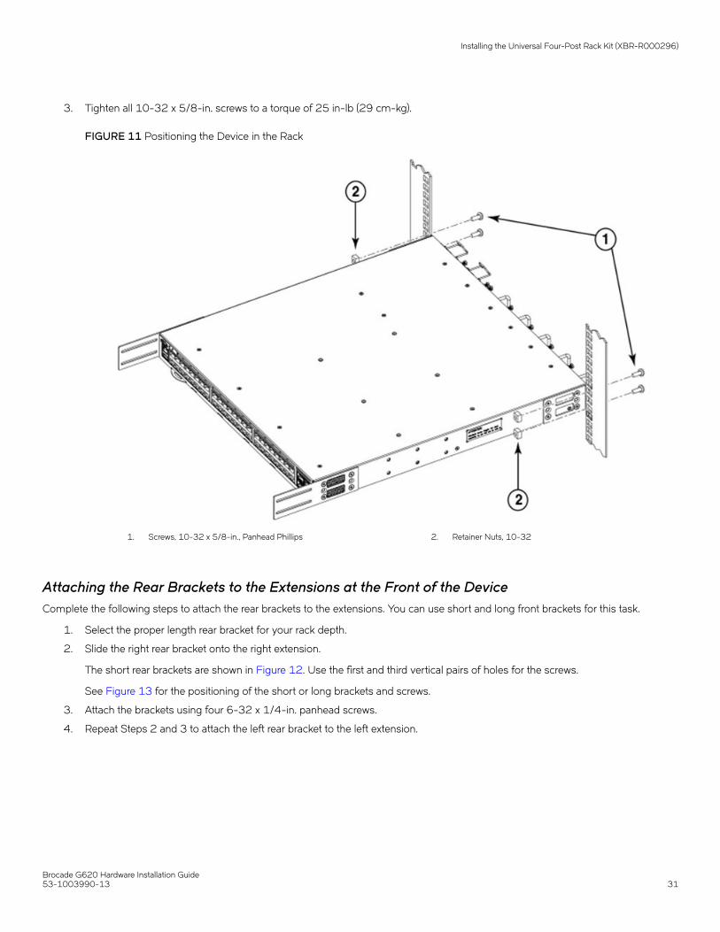
3. Tighten all 10-32 x 5/8-in. screws to a torque of 25 in-lb (29 cm-kg).
FIGURE 11 Positioning the Device in the Rack
1. Screws, 10-32 x 5/8-in., Panhead Phillips 2. Retainer Nuts, 10-32
Attaching the Rear Brackets to the Extensions at the Front of the DeviceComplete the following steps to attach the rear brackets to the extensions. You can use short and long front brackets for this task.
1. Select the proper length rear bracket for your rack depth.
2. Slide the right rear bracket onto the right extension.
The short rear brackets are shown in Figure 12. Use the first and third vertical pairs of holes for the screws.
See Figure 13 for the positioning of the short or long brackets and screws.
3. Attach the brackets using four 6-32 x 1/4-in. panhead screws.
4. Repeat Steps 2 and 3 to attach the left rear bracket to the left extension.
Installing the Universal Four-Post Rack Kit (XBR-R000296)
Brocade G620 Hardware Installation Guide53-1003990-13 31

5. Adjust the brackets to the rack depth and tighten all 6-32 x 1/4-in. screws to a torque of 9 in-lb (10 cm-kg).
FIGURE 12 Attaching the Rear Brackets to the Extensions at the Front of the Device
1. Rear Brackets, Short 2. Screws, 6-32 x 1/4-in., Panhead Phillips
FIGURE 13 Attaching the Short or Long Rear Brackets to the Extensions
Installing the Universal Four-Post Rack Kit (XBR-R000296)
Brocade G620 Hardware Installation Guide32 53-1003990-13
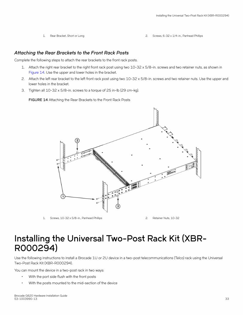
1. Rear Bracket, Short or Long 2. Screws, 6-32 x 1/4-in., Panhead Phillips
Attaching the Rear Brackets to the Front Rack PostsComplete the following steps to attach the rear brackets to the front rack posts.
1. Attach the right rear bracket to the right front rack post using two 10-32 x 5/8-in. screws and two retainer nuts, as shown in Figure 14. Use the upper and lower holes in the bracket.
2. Attach the left rear bracket to the left front rack post using two 10-32 x 5/8-in. screws and two retainer nuts. Use the upper andlower holes in the bracket.
3. Tighten all 10-32 x 5/8-in. screws to a torque of 25 in-lb (29 cm-kg).
FIGURE 14 Attaching the Rear Brackets to the Front Rack Posts
1. Screws, 10-32 x 5/8-in., Panhead Phillips 2. Retainer Nuts, 10-32
Installing the Universal Two-Post Rack Kit (XBR-R000294)Use the following instructions to install a Brocade 1U or 2U device in a two-post telecommunications (Telco) rack using the UniversalTwo-Post Rack Kit (XBR-R000294).
You can mount the device in a two-post rack in two ways:
• With the port side flush with the front posts
• With the posts mounted to the mid-section of the device
Installing the Universal Two-Post Rack Kit (XBR-R000294)
Brocade G620 Hardware Installation Guide53-1003990-13 33

Observe the following when mounting this device:
• Two people are required to install the device in a rack. One person should hold the device, while the other while the other screwsin the front and rear brackets.
• Before mounting your device, review any specific installation and facility requirements in the hardware installation guide for thedevice.
• Hardware devices illustrated in these procedures are for reference only and may not depict the device that you are installing intothe rack.
Time and Items RequiredAllow 15 to 30 minutes to complete the installation.
The following items are required to install the device using the Universal Two-Post Rack Kit:
• #2 Phillips torque screwdriver
• 1/4-inch slotted-blade torque screwdriver
Parts ListThe following parts are provided with the Universal Two-Post Rack Kit (XBR-R000294).
Installing the Universal Two-Post Rack Kit (XBR-R000294)
Brocade G620 Hardware Installation Guide34 53-1003990-13
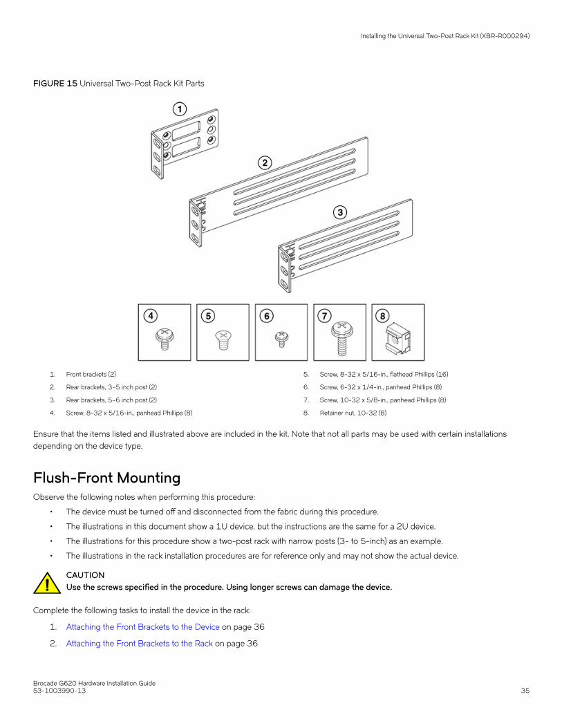
FIGURE 15 Universal Two-Post Rack Kit Parts
1. Front brackets (2)
2. Rear brackets, 3–5 inch post (2)
3. Rear brackets, 5–6 inch post (2)
4. Screw, 8-32 x 5/16-in., panhead Phillips (8)
5. Screw, 8-32 x 5/16-in., flathead Phillips (16)
6. Screw, 6-32 x 1/4-in., panhead Phillips (8)
7. Screw, 10-32 x 5/8-in., panhead Phillips (8)
8. Retainer nut, 10-32 (8)
Ensure that the items listed and illustrated above are included in the kit. Note that not all parts may be used with certain installationsdepending on the device type.
Flush-Front MountingObserve the following notes when performing this procedure:
• The device must be turned off and disconnected from the fabric during this procedure.
• The illustrations in this document show a 1U device, but the instructions are the same for a 2U device.
• The illustrations for this procedure show a two-post rack with narrow posts (3- to 5-inch) as an example.
• The illustrations in the rack installation procedures are for reference only and may not show the actual device.
CAUTIONUse the screws specified in the procedure. Using longer screws can damage the device.
Complete the following tasks to install the device in the rack:
1. Attaching the Front Brackets to the Device on page 36
2. Attaching the Front Brackets to the Rack on page 36
Installing the Universal Two-Post Rack Kit (XBR-R000294)
Brocade G620 Hardware Installation Guide53-1003990-13 35

3. Attaching the Rear Brackets to the Rack on page 37
4. Attaching the Rear Brackets to the Device on page 38
Attaching the Front Brackets to the DeviceComplete the following steps to attach the front brackets to the device.
1. Position the right front bracket with the flat side against the right side of the device, as shown in Figure 16.
2. Insert four 8-32 x 5/16-in. flathead screws through the vertically aligned holes in the bracket and then into the holes on theside of the device. Use the upper and lower screw holes, leaving the center holes empty.
3. Repeat Steps 1 and 2 to attach the left front bracket to the left side of the device.
4. Tighten all the 8-32 x 5/16-in. screws to a torque of 15 in-lb (17 cm-kg).
FIGURE 16 Attaching the Front Brackets
1. The Brocade Device
2. Front Brackets, Right and Left
3. Screws, 8-32 x 5/16-in., Flathead Phillips
Attaching the Front Brackets to the RackComplete the following steps to install the device in the rack.
1. Position the device in the rack, as shown in (Figure 17), providing temporary support under the device until the rack kit is fullysecured to the rack.
2. Attach the right front bracket to the right rack upright using two 10-32 x 5/8-in. panhead screws and two retainer nuts. Use theupper and lower holes in the bracket.
Installing the Universal Two-Post Rack Kit (XBR-R000294)
Brocade G620 Hardware Installation Guide36 53-1003990-13

3. Attach the left front bracket to the left rack upright using two 10-32 x 5/8-in. panhead screws and two retainer nuts.
Use the upper and lower holes in the bracket.
4. Tighten all the 10-32 x 5/8-in. screws to a torque of 25 in-lb. (29 cm-kg).
FIGURE 17 Attaching the Front Brackets to the Rack
1. Screws, 10-32 x 5/8-in., Panhead Phillips 2. Retainer Nuts, 10-32
Attaching the Rear Brackets to the RackComplete the following steps to attach the rear brackets to the rack.
1. Select the proper length bracket for your post width. If your posts are 3 to 5 inches wide, use the brackets marked 3-5 INCH. Ifyour posts are 5 to 6 inches wide, use the brackets marked 5-6 INCH.
2. Position the right rear bracket in the right rear of the device, as shown in Figure 18.
3. Attach the bracket to the right rack upright using two 10-32 x 5/8-in. panhead screws and two retainer nuts. Use the upper andlower holes in the bracket.
4. Repeat Steps 2 and 3 to attach the left rear bracket to the left rack upright.
Installing the Universal Two-Post Rack Kit (XBR-R000294)
Brocade G620 Hardware Installation Guide53-1003990-13 37
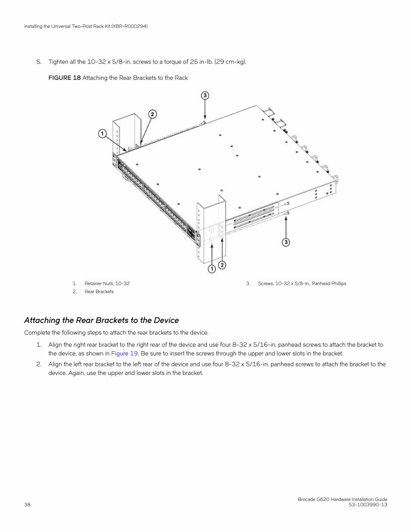
5. Tighten all the 10-32 x 5/8-in. screws to a torque of 25 in-lb. (29 cm-kg).
FIGURE 18 Attaching the Rear Brackets to the Rack
1. Retainer Nuts, 10-32
2. Rear Brackets
3. Screws, 10-32 x 5/8-in., Panhead Phillips
Attaching the Rear Brackets to the DeviceComplete the following steps to attach the rear brackets to the device.
1. Align the right rear bracket to the right rear of the device and use four 8-32 x 5/16-in. panhead screws to attach the bracket tothe device, as shown in Figure 19. Be sure to insert the screws through the upper and lower slots in the bracket.
2. Align the left rear bracket to the left rear of the device and use four 8-32 x 5/16-in. panhead screws to attach the bracket to thedevice. Again, use the upper and lower slots in the bracket.
Installing the Universal Two-Post Rack Kit (XBR-R000294)
Brocade G620 Hardware Installation Guide38 53-1003990-13
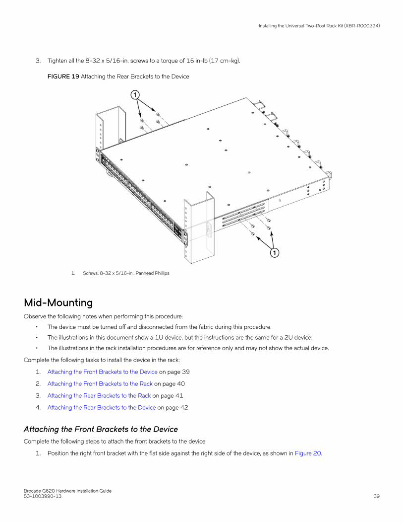
3. Tighten all the 8-32 x 5/16-in. screws to a torque of 15 in-lb (17 cm-kg).
FIGURE 19 Attaching the Rear Brackets to the Device
1. Screws, 8-32 x 5/16-in., Panhead Phillips
Mid-MountingObserve the following notes when performing this procedure:
• The device must be turned off and disconnected from the fabric during this procedure.
• The illustrations in this document show a 1U device, but the instructions are the same for a 2U device.
• The illustrations in the rack installation procedures are for reference only and may not show the actual device.
Complete the following tasks to install the device in the rack:
1. Attaching the Front Brackets to the Device on page 39
2. Attaching the Front Brackets to the Rack on page 40
3. Attaching the Rear Brackets to the Rack on page 41
4. Attaching the Rear Brackets to the Device on page 42
Attaching the Front Brackets to the DeviceComplete the following steps to attach the front brackets to the device.
1. Position the right front bracket with the flat side against the right side of the device, as shown in Figure 20.
Installing the Universal Two-Post Rack Kit (XBR-R000294)
Brocade G620 Hardware Installation Guide53-1003990-13 39

2. Insert four 8-32 x 5/16-in. flathead screws through the vertically aligned holes in the bracket and then into the holes on theside of the device. Use the upper and lower screw holes, leaving the center holes empty.
3. Repeat Steps 1 and 2 to attach the left front bracket to the left side of the device.
4. Tighten all 8-32 x 5/16-in. screws to a torque of 15 in-lb (17 cm-kg).
FIGURE 20 Attaching the Front Brackets
1. The Brocade Device
2. Front Brackets, Right and Left
3. Screws, 8-32 x 5/16-in., Flathead Phillips
Attaching the Front Brackets to the RackComplete the following steps to install the device in the rack.
1. Position the device in the rack, as shown in Figure 21, providing temporary support under the device until the rack kit is fullysecured to the rack.
2. Attach the right front bracket to the right rack upright using two 10-32 x 5/8-in. screws and two retainer nuts. Use the upperand lower holes in the bracket.
3. Attach the left front bracket to the left rack upright using two 10-32 x 5/8-in. screws and two retainer nuts. Use the upper andlower holes in the bracket.
Installing the Universal Two-Post Rack Kit (XBR-R000294)
Brocade G620 Hardware Installation Guide40 53-1003990-13
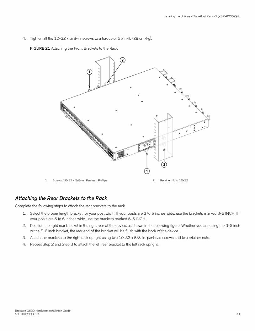
4. Tighten all the 10-32 x 5/8-in. screws to a torque of 25 in-lb (29 cm-kg).
FIGURE 21 Attaching the Front Brackets to the Rack
1. Screws, 10-32 x 5/8-in., Panhead Phillips 2. Retainer Nuts, 10-32
Attaching the Rear Brackets to the RackComplete the following steps to attach the rear brackets to the rack.
1. Select the proper length bracket for your post width. If your posts are 3 to 5 inches wide, use the brackets marked 3-5 INCH. Ifyour posts are 5 to 6 inches wide, use the brackets marked 5-6 INCH.
2. Position the right rear bracket in the right rear of the device, as shown in the following figure. Whether you are using the 3-5 inchor the 5-6 inch bracket, the rear end of the bracket will be flush with the back of the device.
3. Attach the brackets to the right rack upright using two 10-32 x 5/8-in. panhead screws and two retainer nuts.
4. Repeat Step 2 and Step 3 to attach the left rear bracket to the left rack upright.
Installing the Universal Two-Post Rack Kit (XBR-R000294)
Brocade G620 Hardware Installation Guide53-1003990-13 41

5. Tighten all the 10-32 x 5/8-in. screws to a torque of 25 in-lb (29 cm-kg).
FIGURE 22 Attaching the Rear Brackets to the Rack
1. Retainer Nuts, 10-32
2. Rear Brackets (Right and Left)
3. Screws, 10-32 x 5/8-in., Panhead Phillips
Attaching the Rear Brackets to the DeviceComplete the following steps to attach the rear brackets to the device.
1. Align the right rear bracket to the right rear of the device and use four 8-32 x 5/16-in. panhead screws to attach the bracket tothe device, as shown in Figure 23. Be sure to insert the screws through the upper and lower slots in the bracket.
2. Align the left rear bracket to the left rear of the device and use four 8-32 x 5/16-in. panhead screws to attach the bracket to thedevice. Again, use the upper and lower slots in the bracket.
Installing the Universal Two-Post Rack Kit (XBR-R000294)
Brocade G620 Hardware Installation Guide42 53-1003990-13
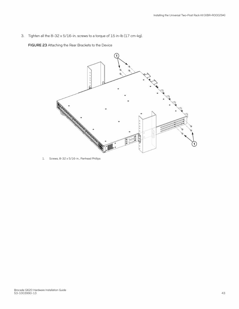
3. Tighten all the 8-32 x 5/16-in. screws to a torque of 15 in-lb (17 cm-kg).
FIGURE 23 Attaching the Rear Brackets to the Device
1. Screws, 8-32 x 5/16-in., Panhead Phillips
Installing the Universal Two-Post Rack Kit (XBR-R000294)
Brocade G620 Hardware Installation Guide53-1003990-13 43

Initial Setup and Verification• Items Required....................................................................................................................................................................................................44• Providing Power to the Device.....................................................................................................................................................................44• Establishing a First-Time Serial Connection.......................................................................................................................................... 45• Configuring the IP Address........................................................................................................................................................................... 46• Setting the Date and Time............................................................................................................................................................................. 46• Customizing the Chassis Name and Switch Name............................................................................................................................ 48• Establishing an Ethernet Connection........................................................................................................................................................ 48• Setting the Domain ID..................................................................................................................................................................................... 49• Verifying correct operation.............................................................................................................................................................................49• Backing Up the Configuration......................................................................................................................................................................51• Powering Down the Device........................................................................................................................................................................... 51
Items RequiredThe following items are required for initial setup and verification of the device:
• The device, mounted and installed with the required power supply and fan assemblies, transceivers, and cables; and connectedto a power source.
• A workstation computer with a terminal emulator application installed, such as PuTTY, XShell, or SecureCRT on Windows.
• An unused IP address with a corresponding subnet mask and gateway address.
• A serial cable with an RJ-45 connector.
• An Ethernet cable.
• Access to an FTP server or USB device for backing up (uploading) or downloading the device configuration (optional).
Providing Power to the DevicePerform the following steps to provide power to the device.
1. Connect the power cords to both power supplies, and then to power sources on separate circuits to protect against powerfailure. Ensure that the power cords have a minimum service loop of 6 inches available and are routed to avoid stress.
2. Power on the power supplies by flipping both switches to the on position (the "I" symbol). The power supply LEDs displayamber until the power-on self-test (POST) is complete, and then the LEDs change to green. The switch usually requires severalminutes to boot and complete the POST.
NOTEPower is supplied to the device as soon as the first power supply is connected and turned on.
3. After the POST is complete, verify that the switch power and switch status LEDs are green.
For more information about how to interpret the POST, BOOT, and diagnostics tests, refer to Monitoring the Device on page60.
Brocade G620 Hardware Installation Guide44 53-1003990-13

Establishing a First-Time Serial ConnectionPerform the following steps to log in to the device through a serial connection.
1. Connect the serial cable to the serial port on the device and to an RS-232 serial port on the workstation.
If the serial port on the workstation is RJ-45 instead of RS-232, remove the adapter on the end of the serial cable and insertthe exposed RJ-45 connector into the RJ-45 serial port on the workstation.
2. Disable any serial communication programs running on the workstation such as synchronization programs.
3. Open a terminal emulator application such as PuTTY, XShell, or SecureCRT on a Windows PC, or TERM, TIP, or C-Kermit in aLinux environment, and configure the application as follows:
• In a Windows environment, use the following values:
Parameter Value
Bits per second 9600
Databits 8
Parity None
Stop bits 1
Flow control None (must be disabled on the host side)
NOTEFlow control is not supported on the serial connection when attached to a remote terminal and must be disabledon the customer-side remote terminal server in addition to the host-side clients.
• In a UNIX environment using TIP, enter the following string at the prompt:
tip /dev/ttyb -9600
If ttyb is already in use, use ttya instead and enter the following string at the prompt:
tip /dev/ttya -96004. When the terminal emulator application stops reporting information, press Enter to display the login prompt.
Switch Console Login:5. Log on to the device as admin, using the default password (password). You are prompted to change the default user name and
password at initial login. Make sure to write down the new credentials and keep this information in a secure location.
Fabric OS (swDir)swDir login: adminPassword:Please change your passwords now.Use Control-C to exit or press 'Enter' key to proceed.swDir:admin>
6. Modify the credentials. To cancel, press Ctrl+C.
NOTEInitial passwords can be 8 to 40 characters long. They must begin with an alphabetic character. They can includenumeric characters, the period (.), and the underscore (_) only. Passwords are case-sensitive, and they are notdisplayed when you enter them on the command line.
Establishing a First-Time Serial Connection
Brocade G620 Hardware Installation Guide53-1003990-13 45
Configuring the IP AddressYou can configure the device with a static IP address, or you can use a Dynamic Host Configuration Protocol (DHCP) server to set the IPaddress of the switch. DHCP is enabled by default. The device supports both IPv4 and IPv6 addresses.
Using DHCP to Set the IP AddressWhen using DHCP, the switch obtains its IP address, subnet mask, and default gateway address from the DHCP server. The DHCPclient can connect only to a DHCP server that is on the same subnet as the switch. If your DHCP server is not on the same subnet as theswitch, use a static IP address.
Setting a Static IP AddressTo set a static IP address for the device, complete the following steps.
1. Log in to the device as admin.
2. Use the ipaddrset command to set the Ethernet IP address.
• If you are going to use an IPv4 address, enter the IP address in dotted decimal notation as prompted.
Ethernet IP Address: [192.168.74.102]• If you are going to use an IPv6 address, enter the network information in colon-separated notation as prompted.
device:admin> ipaddrset -ipv6 --add 1080::8:800:200C:417A/64IP address is being changed...Done.
3. Complete the rest of the network information as prompted. (IPv4 format shown):
Ethernet Subnetmask: [255.255.255.0]Ethernet IP Address: [192.168.74.102]Gateway IP Address: [192.168.74.1]
4. Enter off to disable DHCP when prompted.
DHCP [OFF]: off
Setting the Date and TimeThe date and time settings are used for logging events, error detection, and troubleshooting. However, device operation does not dependon the date and time; a device with incorrect date or time values still functions properly.
You can synchronize the local time of the principal or primary fabric configuration server (FCS) device to that of an external Network TimeProtocol (NTP) server.
Perform the following steps to set the date and time.
1. Log in to the device as admin.
Configuring the IP Address
Brocade G620 Hardware Installation Guide46 53-1003990-13

2. Enter the date newdate command at the command line.
The newdate variable specifies the new date and time enclosed in double quotation marks. The operand is optional; if omitted,
the current date and time are displayed. Date and time are specified as a string in the mmddhhmmyy format:
• mm: Specifies the month. Valid values are 01 to 12.
• dd: Specifies the date. Valid values are 01 to 31.
• hh: Specifies the hour. Valid values are 00 to 23.
• mm: Specifies the minutes. Valid values are 00 to 59.
• yy: Specifies the year, valid values are 00 to 37 and 70 to 99. Year values from 70 to 99 are interpreted as 1970 to1999; year values from 00 to 37 are interpreted as 2000 to 2037.
device:admin> dateThu Dec 22 14:05:10 UTC 2016device:admin> date "1222150617"Thu Dec 22 15:06:00 UTC 2017
Setting the Time ZoneThe default time zone is Coordinated Universal Time (UTC). The time zone must be set only once because the value is stored innonvolatile memory. Use the following procedure to set the time zone.
1. Log in as admin.
2. Use the tsTimeZone --interactive command and follow the prompts, or enter the tsTimeZone-
[houroffset,minuteoffset] command as follows:
For Pacific Standard Time, enter tsTimeZone -8,0.
For Central Standard Time, enter tsTimeZone -6,0.
For Eastern Standard Time, enter tsTimeZone -5,0.
TABLE 8 tsTimeZone Command Parameter Selection for the U.S. tTme Zones
Local Time tsTimeZone Parameter (Difference from UTC)
Atlantic Standard -4,0
Atlantic Daylight -3,0
Eastern Standard -5,0
Eastern Daylight -4,0
Central Standard -6,0
Central Daylight -5,0
Mountain Standard -7,0
Mountain Daylight -6,0
Pacific Standard -8,0
Pacific Daylight -7,0
Alaskan Standard -9,0
Alaskan Daylight -8,0
Hawaiian Standard -10,0
Setting the Date and Time
Brocade G620 Hardware Installation Guide53-1003990-13 47

Synchronizing the Local Time with an External SourcePerform the following steps to synchronize the local time of the principal or primary FCS device with that of an external NTP server.
1. Log in as admin.
2. Enter the tsClockServer-ipaddr command.
The ipaddr variable represents the IP address of the NTP server that the device can access. This variable is optional; by default,the value is "LOCL".
switch:admin> tsclockserver 192.168.126.60Updating Clock Server configuration...done.Updated with the NTP servers
Customizing the Chassis Name and Switch NameChanging the chassis and switch names is important for uniquely distinguishing and identifying the device uniquely and for accuratetracking of logs and errors. The messages that appear in the log are labeled with the switch name or chassis name, which makes trackingthe errors much easier. Specify an easily understandable and meaningful name for the chassis and switch names.
Perform the following steps to change the chassis name and then the switch name.
1. Log in to the device through Telnet using the admin account.
2. Change the chassis name by using the chassisName command.
device:admin> chassisname Chassis_001
3. Change the switch name by using the switchName command.
device:admin> switchname Switch_001Committing configuration...DoneSwitch name has been changed. Please re-login to the switch for the change to applied
Establishing an Ethernet ConnectionPerform the following steps to establish an Ethernet connection to the device.
1. Remove the plug from the Ethernet port.
2. Connect an Ethernet cable to the device Ethernet port and to the workstation or to an Ethernet network that connects theworkstation.
NOTEAt this point, the device can be accessed remotely, using either the command line or Brocade Web Tools. Ensure thatthe device is not being modified from any other connections during the remaining tasks in this chapter. The Ethernetmanagement port also supports Auto MDI/MDIX.
Customizing the Chassis Name and Switch Name
Brocade G620 Hardware Installation Guide48 53-1003990-13

Setting the Domain IDPerform the following steps to set the switch domain ID.
1. Log in to the switch through Telnet using the admin account.
2. Modify the domain ID if required.
The default domain ID is 1. If the switch is not powered on until after it is connected to the fabric and the default domain ID isalready in use, the domain ID for the new switch is automatically reset to a unique value. If the switch is connected to the fabricafter it has been powered on and the default domain ID is already in use, the fabric segments. To find the domain IDs that arecurrently in use, enter the fabricShow command on another switch in the fabric.
Perform the following steps to modify the domain ID.
a) Disable the switch by entering the switchDisable command.
b) Enter the configure command. The command prompts display sequentially; enter a new value or press Enter to accept
each default value.
c) Enter y after the Fabric param prompt.
Fabric param (yes, y, no, n): [no] y
d) Enter a unique domain ID (such as the domain ID used by the previous switch, if still available).
Domain: (1..239) [1] 3
e) Complete the remaining prompts or press Ctrl+D to accept the remaining settings without completing all the prompts.
f) Re-enable the switch by entering the switchEnable command.
Verifying correct operationPerform the following steps to verify correct operation of the device.
1. Check the LEDs to verify that all components are functional.
Verifying correct operation
Brocade G620 Hardware Installation Guide53-1003990-13 49

2. Verify the correct operation of the device by entering the following commands from the workstation.
Command Description
psShow Displays power supply status and information
fanShow Displays fans status and information
switchShow Displays switch status and information
tempShow Displays temperature status and information
historyShow Displays the device history
errDump Displays any errors
The switchShow command provides the following information about the device and ports status.
sb_70:admin> switchshowswitchName: sb_70switchType: 162.0switchState: OnlineswitchMode: NativeswitchRole: SubordinateswitchDomain: 70switchId: fffc46switchWwn: 10:00:00:05:1e:65:79:04zoning: ON (PERF_CFG)switchBeacon: OFFFC Router: OFFFabric Name: abcfabricAllow XISL Use: OFFLS Attributes: [FID: 128, Base Switch: No, Default Switch: Yes, Address Mode 0]Index Port Address Media Speed State Proto==================================================0 0 460000 id N32 Online FC F-Port 20:05:00:11:0d:a8:01:001 1 460100 id N32 Online FC F-Port 20:01:00:11:0d:bb:01:002 2 460200 id N32 Online FC F-Port 20:03:00:11:0d:84:01:003 3 460300 id N32 Online FC F-Port 20:07:00:11:0d:26:01:004 4 460400 id N32 Online FC F-Port 10:00:8c:7c:ff:5c:c5:015 5 460500 id N32 Online FC F-Port 10:00:8c:7c:ff:58:4c:006 6 460600 id N32 Online FC F-Port 10:00:8c:7c:ff:5c:c9:017 7 460700 id N32 Online FC F-Port 10:00:8c:7c:ff:5c:bd:008 8 460800 -- N32 No_Module FC9 9 460900 -- N32 No_Module FC10 10 460a00 -- N32 No_Module FC11 11 460b00 -- N32 No_Module FC12 12 460c00 -- N32 No_Module FC13 13 460d00 -- N32 No_Module FC14 14 460e00 -- N32 No_Module FC15 15 460f00 -- N32 No_Module FC16 16 461000 -- N32 No_Module FC17 17 461100 -- N32 No_Module FC18 18 461200 -- N32 No_Module FC19 19 461300 -- N32 No_Module FC20 20 461400 -- N32 No_Module FC21 21 461500 -- N32 No_Module FC22 22 461600 -- N32 No_Module FC23 23 461700 -- N32 No_Module FC<Output truncated>
Verifying correct operation
Brocade G620 Hardware Installation Guide50 53-1003990-13
Backing Up the ConfigurationBrocade recommends backing up the configuration on a regular basis to ensure that a complete configuration is available fordownloading to a replacement switch.
1. Log in to the device as the admin user.
2. Back up the device configuration to an FTP server by entering the configUpload command and following the prompts.
sb_70:admin> configuploadProtocol (scp, ftp, local) [ftp]:Server Name or IP Address [host]: 192.168.0.100 User Name [user]: anonymousPath/Filename [<home dir>/config.txt]: /dumps/supportsave/pz/switch85/G20-1.txtSection (all|chassis|switch [all]): allconfigUpload complete: All selected config parameters are uploaded
This command uploads the device configuration to the server, making it available for downloading to a replacement device ifnecessary.
NOTEIf Virtual Fabrics (VF) is enabled, you must enter configUpload for each VF separately.
Powering Down the DeviceComplete the following steps to power down the device.
1. Shut down the Fabric OS software using the sysShutdown command.
2. Identify the power-on switches in the nonport-side of the device.
3. Power off both power supplies by setting each power switch to the “O” position.
4. Unplug the power cables from the power source before servicing the device or FRUs.
All devices are returned to their initial state the next time the switch is powered on.
Powering Down the Device
Brocade G620 Hardware Installation Guide53-1003990-13 51

Installing Transceivers and Cables• Time and Items Required............................................................................................................................................................................... 52• Precautions Specific to Transceivers and Cables.................................................................................................................................53• Cleaning the Fiber-Optic Connectors.......................................................................................................................................................53• Managing Cables...............................................................................................................................................................................................53• Replacing an SFP+ Transceiver...................................................................................................................................................................54• Installing a QSFP Transceiver...................................................................................................................................................................... 56• Replacing a QSFP Transceiver.................................................................................................................................................................... 57• Verifying the Operation of New Transceivers.........................................................................................................................................58
Time and Items RequiredThe installation or replacement procedure for one transceiver takes less than 5 minutes. Ensure that the following items are available:
• Required number of compatible power cables
• Required number of supported Brocade-branded transceivers
For current information on qualified transceivers supported by this device, refer to the "Brocade Fibre Channel TransceiverPlatform Support Matrix" and applicable transceiver data sheets on www.broadcom.com.
DANGERUse only optical transceivers that are qualified by Brocade Communications Systems LLC and comply with theFDA Class 1 radiation performance requirements defined in 21 CFR Subchapter I, and with IEC 60825 andEN60825. Optical products that do not comply with these standards might emit light that is hazardous to theeyes.
• Required number of compatible fiber-optic cables
• Optical transceiver extraction tool
NOTEMany Brocade switches, backbones, and directors come with a transceiver extraction tool and holster. The extractiontool is designed to remove transceivers from modules where the space is limited. If you did not receive this tool withyour product, you can order it from Brocade using part number XBR-48000-R0129.
Brocade G620 Hardware Installation Guide52 53-1003990-13
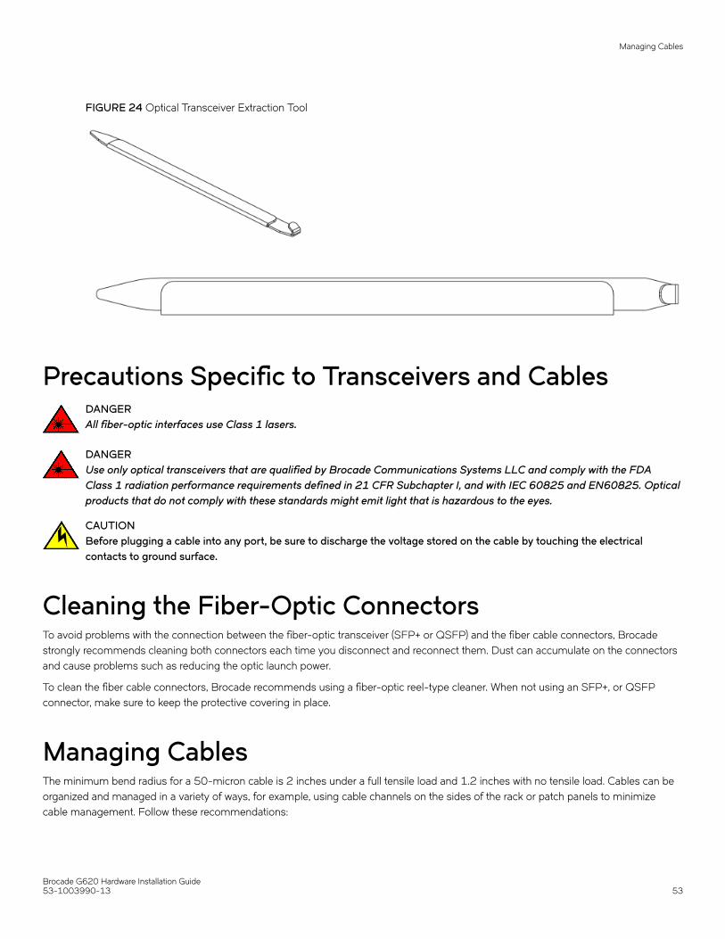
FIGURE 24 Optical Transceiver Extraction Tool
Precautions Specific to Transceivers and CablesDANGERAll fiber-optic interfaces use Class 1 lasers.
DANGERUse only optical transceivers that are qualified by Brocade Communications Systems LLC and comply with the FDAClass 1 radiation performance requirements defined in 21 CFR Subchapter I, and with IEC 60825 and EN60825. Opticalproducts that do not comply with these standards might emit light that is hazardous to the eyes.
CAUTIONBefore plugging a cable into any port, be sure to discharge the voltage stored on the cable by touching the electricalcontacts to ground surface.
Cleaning the Fiber-Optic ConnectorsTo avoid problems with the connection between the fiber-optic transceiver (SFP+ or QSFP) and the fiber cable connectors, Brocadestrongly recommends cleaning both connectors each time you disconnect and reconnect them. Dust can accumulate on the connectorsand cause problems such as reducing the optic launch power.
To clean the fiber cable connectors, Brocade recommends using a fiber-optic reel-type cleaner. When not using an SFP+, or QSFPconnector, make sure to keep the protective covering in place.
Managing CablesThe minimum bend radius for a 50-micron cable is 2 inches under a full tensile load and 1.2 inches with no tensile load. Cables can beorganized and managed in a variety of ways, for example, using cable channels on the sides of the rack or patch panels to minimizecable management. Follow these recommendations:
Managing Cables
Brocade G620 Hardware Installation Guide53-1003990-13 53

NOTEYou should not use tie wraps with optical cables because they are easily overtightened and can damage the optic fibers.
CAUTIONBefore plugging a cable into any port, be sure to discharge the voltage stored on the cable by touching the electricalcontacts to ground surface.
• Plan for the proper rack space required for cable management before installing the switch.
• Leave at least 1m (3.28 ft) of slack for each port cable. This slack provides room to remove and replace the switch, allows forinadvertent movement of the rack, and helps prevent the cables from being bent to less than the minimum bend radius.
• If you are using Brocade ISL Trunking, consider grouping cables by trunking groups. The cables used in trunking groups mustmeet specific requirements, as described in the Brocade Fabric OS Administratorion Guide .
• For easier maintenance, label the fiber-optic cables and record the devices to which they connect.
• Keep LEDs visible by routing port cables and other cables away from the LEDs.
• Use hook and loop style straps to secure and organize fiber-optic cables.
Replacing an SFP+ TransceiverComplete the following steps to remove and then install a new SFP+ transceiver.
NOTE16 and 32Gb/s SFP+ transceivers have pull tabs instead of bails. Always use the pull tab to insert or remove the SFP+transceivers, as the SFP might be hot.
1. Remove any cables that are inserted into the transceiver.
2. Grasp the SFP+ transceiver pull tab and pull the tab straight out.
NOTEGrasp the tab near the body of the transceiver to reduce the chances of bending the pull tab. As the SFP may be hot,avoid touching it.
Replacing an SFP+ Transceiver
Brocade G620 Hardware Installation Guide54 53-1003990-13

3. To insert the replacement transceiver, use the pull tab on the SFP+ transceiver to carefully push the transceiver into the port.Transceivers are keyed so that they can only be inserted with the correct orientation. If a transceiver does not slide in easily,ensure that it is correctly oriented.
NOTEEach SFP+ transceiver has a 10-pad gold-plated PCB-edge connector on the bottom. The correct position to insertan SFP+ transceiver into the upper row of ports is with the gold edge down. The correct position to insert an SFP+transceiver into the lower row of ports is with the gold edge up.
FIGURE 25 Replacing a 32Gb/s SFP+ Optical Transceiver in an Upper Port
1. Pull tab 2. Transceiver
FIGURE 26 Replacing a 32Gb/s SFP+ Transceiver in a Upper Port
Replacing an SFP+ Transceiver
Brocade G620 Hardware Installation Guide53-1003990-13 55
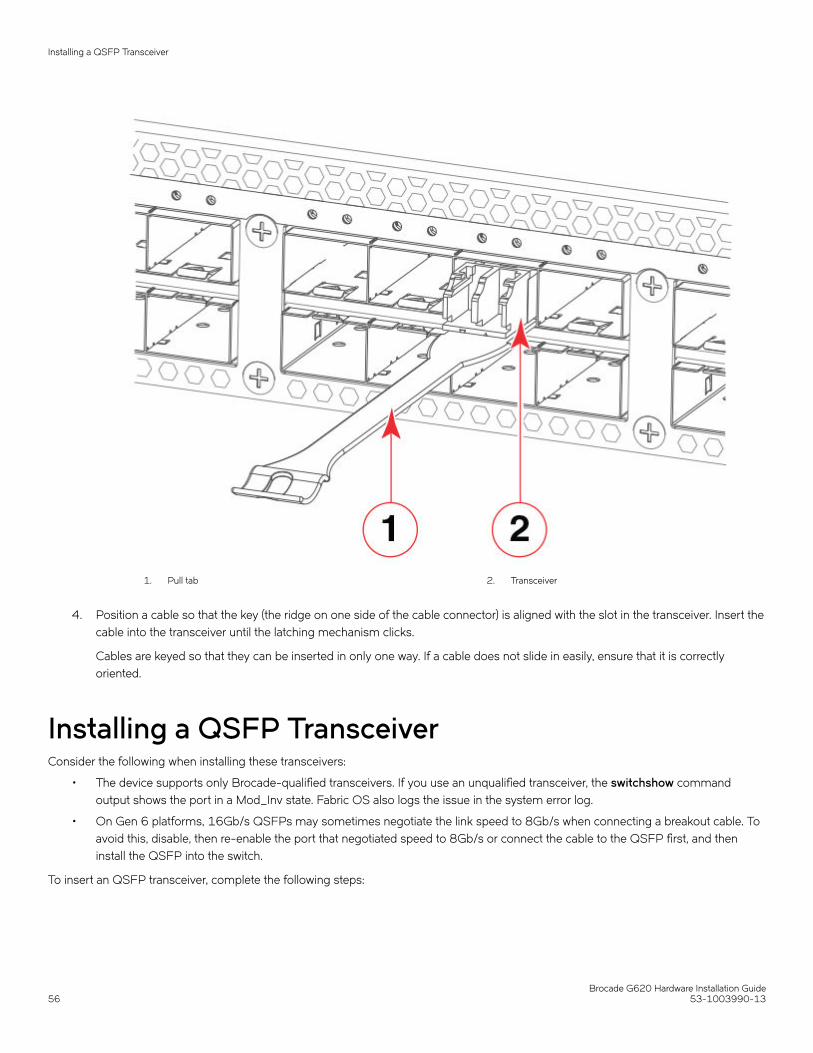
1. Pull tab 2. Transceiver
4. Position a cable so that the key (the ridge on one side of the cable connector) is aligned with the slot in the transceiver. Insert thecable into the transceiver until the latching mechanism clicks.
Cables are keyed so that they can be inserted in only one way. If a cable does not slide in easily, ensure that it is correctlyoriented.
Installing a QSFP TransceiverConsider the following when installing these transceivers:
• The device supports only Brocade-qualified transceivers. If you use an unqualified transceiver, the switchshow commandoutput shows the port in a Mod_Inv state. Fabric OS also logs the issue in the system error log.
• On Gen 6 platforms, 16Gb/s QSFPs may sometimes negotiate the link speed to 8Gb/s when connecting a breakout cable. Toavoid this, disable, then re-enable the port that negotiated speed to 8Gb/s or connect the cable to the QSFP first, and theninstall the QSFP into the switch.
To insert an QSFP transceiver, complete the following steps:
Installing a QSFP Transceiver
Brocade G620 Hardware Installation Guide56 53-1003990-13

NOTEQSFP transceivers have pull tabs rather then bails. Always use the pull tab to insert or remove the QSFP transceivers, as theQSFP might be hot.
1. Use the pull tab on these transceivers to help push the transceiver into the port. Transceivers are keyed so that they can only beinserted with the correct orientation. If a transceiver does not slide in easily, ensure that it is correctly oriented. Push the correctlyoriented transceiver into the port until it is firmly seated and the latching mechanism clicks.
FIGURE 27 Installing a 32Gb/s QSFP Transceiver in an Upper Port
1. Pull tab
2. QSFP cable
3. QSFP transceiver
2. Position a cable so that the key (the ridge on one side of the cable connector) is aligned with the slot in the transceiver. Insert thecable into the transceiver until the latching mechanism clicks.
NOTECables are keyed so that they can be inserted in only one way. If a cable does not slide in easily, ensure that it iscorrectly oriented. Do not insert any unsupported cable intended for an other type of transceiver into a regular QSFPtransceiver. You may damage the cable as well as the transceiver.
Replacing a QSFP TransceiverConsider the following when installing these transceivers:
• The device supports only Brocade-qualified transceivers. If you use an unqualified transceiver, the switchshow commandoutput shows the port in a Mod_Inv state. Fabric OS also logs the issue in the system error log.
• On Gen 6 platforms, 16Gb/s QSFPs may sometimes negotiate the link speed to 8Gb/s when connecting a breakout cable. Toavoid this, disable, then re-enable the port that negotiated speed to 8Gb/s or connect the cable to the QSFP first, and theninstall the QSFP into the switch.
Complete the following steps to remove and then install a new QSFP transceiver.
Replacing a QSFP Transceiver
Brocade G620 Hardware Installation Guide53-1003990-13 57
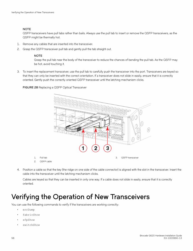
NOTEQSFP transceivers have pull tabs rather than bails. Always use the pull tab to insert or remove the QSFP transceivers, as theQSFP might be thermally hot.
1. Remove any cables that are inserted into the transceiver.
2. Grasp the QSFP transceiver pull tab and gently pull the tab straight out.
NOTEGrasp the pull tab near the body of the transceiver to reduce the chances of bending the pull tab. As the QSFP maybe hot, avoid touching it.
3. To insert the replacement transceiver, use the pull tab to carefully push the transceiver into the port. Transceivers are keyed sothat they can only be inserted with the correct orientation. If a transceiver does not slide in easily, ensure that it is correctlyoriented. Gently push the correctly oriented QSFP transceiver until the latching mechanism clicks.
FIGURE 28 Replacing a QSFP Optical Transceiver
1. Pull tab
2. QSFP cable
3. QSFP transceiver
4. Position a cable so that the key (the ridge on one side of the cable connector) is aligned with the slot in the transceiver. Insert thecable into the transceiver until the latching mechanism clicks.
Cables are keyed so that they can be inserted in only one way. If a cable does not slide in easily, ensure that it is correctlyoriented.
Verifying the Operation of New TransceiversYou can use the following commands to verify if the transceivers are working correctly:
• errDump• fabricShow• sfpShow• switchShow
Verifying the Operation of New Transceivers
Brocade G620 Hardware Installation Guide58 53-1003990-13

Refer to the Brocade Fabric OS Command Reference for output examples and descriptions.
Verifying the Operation of New Transceivers
Brocade G620 Hardware Installation Guide53-1003990-13 59

Monitoring the Device• Interpreting Port-Side LEDs......................................................................................................................................................................... 60• Interpreting Nonport-side LEDs..................................................................................................................................................................63• Interpreting POST Results.............................................................................................................................................................................64• Interpreting BOOT Results............................................................................................................................................................................64• Running Diagnostic Tests...............................................................................................................................................................................65
Interpreting Port-Side LEDsSystem activity and status can be determined through the activity of the LEDs on the switch. There are three possible LED states: nolight, a steady light, and a flashing light. Flashing lights may be slow, fast, or flickering. The lights are green or amber. Sometimes, theLEDs may flash either of the colors during boot, POST, or other diagnostic tests. This is normal; it does not indicate a problem unless theLEDs do not indicate a healthy state after all boot processes and diagnostic tests are complete.
FIGURE 29 Brocade G620 Port-Side LEDs
1. System Status LED
2. System power LED
3. SFP+ (upper) Port 0 Status LED
4. SFP+ (lower) Port 4 Status LED
5. FC Port 52 (QSFP 1) Status LED
6. FC Port 53 (QSFP 1) Status LED
7. FC Port 54 (QSFP 1) Status LED
8. FC Port 55 (QSFP 1) Status LED
9. FC Port 60 (QSFP 3) Status LED
10. FC Port 61 (QSFP 3) Status LED
11. FC Port 62 (QSFP 3) Status LED
12. FC Port 63 (QSFP 3) Status LED
System Power LEDSee the following table to interpret the system power LED.
TABLE 9 System Power LED Patterns During Normal Operation
LED Color Status of Hardware Recommended Action
No light The system is off or there is an internal powersupply failure.
Verify that the system is powered on, that thepower cables are attached, and that your powersource is live.
Brocade G620 Hardware Installation Guide60 53-1003990-13

TABLE 9 System Power LED Patterns During Normal Operation (continued)
LED Color Status of Hardware Recommended Action
If the system power LED is not green, the unitmay be faulty.
Contact your solution provider.
Steady green The system is on and power supplies arefunctioning properly.
No action is required.
System Status LEDSee the following table to interpret the system status LED.
TABLE 10 System Status LED patterns During Normal Operation
LED Color Status of Hardware Recommended Action
No light The system is off or there is no power. Verify that the system is on and has completedbooting.
Steady green The POST and initialization have completed. Thesystem is on and functioning properly.
No action is required.
Steady amber (for more than 5 seconds—cantake over a minute to complete the POST)
System is going through the power-up process. No action is required.
Steady amber (for more than a few minutes) Unknown state, boot failed, or the system isfaulty.
NOTEOnce the POST completes and theswitch has failed, a steady ambercolor may result.
Perform the following steps:
1. Connect a serial cable to the system.
2. Reboot the system.
3. Check the failure indicated on thesystem console
4. Contact your solution provider.
Flashing amber/green Attention is required. A number of variables cancause this status, including a single powersupply failure, a fan failure, or one or moreenvironmental ranges being exceeded.
Check the management interface and the errorlog for details on the cause of the status.
Contact your solution provider.
Management Port LEDRefer to the following table to interpret the Management Port LEDs.
TABLE 11 Management Port LED patterns during normal operation
LED function/state Status of the hardware
Link/SpeedGreen LED: ON 1000Mbps Link
Link/SpeedAmber LED: ON 10/100Mbps Link
ActivityGreen LED: BLINK Presence of activity
FC Port Status LEDSee the following table to interpret the FC port status LEDs.
Interpreting Port-Side LEDs
Brocade G620 Hardware Installation Guide53-1003990-13 61
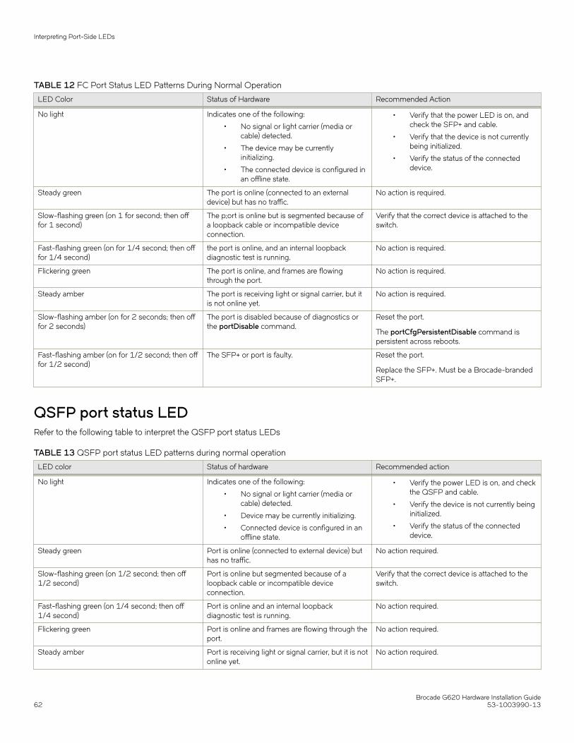
TABLE 12 FC Port Status LED Patterns During Normal Operation
LED Color Status of Hardware Recommended Action
No light Indicates one of the following:
• No signal or light carrier (media orcable) detected.
• The device may be currentlyinitializing.
• The connected device is configured inan offline state.
• Verify that the power LED is on, andcheck the SFP+ and cable.
• Verify that the device is not currentlybeing initialized.
• Verify the status of the connecteddevice.
Steady green The port is online (connected to an externaldevice) but has no traffic.
No action is required.
Slow-flashing green (on 1 for second; then offfor 1 second)
The p;ort is online but is segmented because ofa loopback cable or incompatible deviceconnection.
Verify that the correct device is attached to theswitch.
Fast-flashing green (on for 1/4 second; then offfor 1/4 second)
the port is online, and an internal loopbackdiagnostic test is running.
No action is required.
Flickering green The port is online, and frames are flowingthrough the port.
No action is required.
Steady amber The port is receiving light or signal carrier, but itis not online yet.
No action is required.
Slow-flashing amber (on for 2 seconds; then offfor 2 seconds)
The port is disabled because of diagnostics orthe portDisable command.
Reset the port.
The portCfgPersistentDisable command ispersistent across reboots.
Fast-flashing amber (on for 1/2 second; then offfor 1/2 second)
The SFP+ or port is faulty. Reset the port.
Replace the SFP+. Must be a Brocade-brandedSFP+.
QSFP port status LEDRefer to the following table to interpret the QSFP port status LEDs
TABLE 13 QSFP port status LED patterns during normal operation
LED color Status of hardware Recommended action
No light Indicates one of the following:
• No signal or light carrier (media orcable) detected.
• Device may be currently initializing.
• Connected device is configured in anoffline state.
• Verify the power LED is on, and checkthe QSFP and cable.
• Verify the device is not currently beinginitialized.
• Verify the status of the connecteddevice.
Steady green Port is online (connected to external device) buthas no traffic.
No action required.
Slow-flashing green (on 1/2 second; then off1/2 second)
Port is online but segmented because of aloopback cable or incompatible deviceconnection.
Verify that the correct device is attached to theswitch.
Fast-flashing green (on 1/4 second; then off1/4 second)
Port is online and an internal loopbackdiagnostic test is running.
No action required.
Flickering green Port is online and frames are flowing through theport.
No action required.
Steady amber Port is receiving light or signal carrier, but it is notonline yet.
No action required.
Interpreting Port-Side LEDs
Brocade G620 Hardware Installation Guide62 53-1003990-13
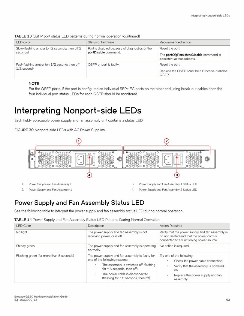
TABLE 13 QSFP port status LED patterns during normal operation (continued)
LED color Status of hardware Recommended action
Slow-flashing amber (on 2 seconds; then off 2seconds)
Port is disabled because of diagnostics or theportDisable command.
Reset the port.
The portCfgPersistentDisable command ispersistent across reboots.
Fast-flashing amber (on 1/2 second; then off1/2 second)
QSFP or port is faulty. Reset the port.
Replace the QSFP. Must be a Brocade-brandedQSFP.
NOTEFor the QSFP ports, if the port is configured as individual SFP+ FC ports on the other end using break-out cables, then thefour individual port status LEDs for each QSFP should be monitored.
Interpreting Nonport-side LEDsEach field-replaceable power supply and fan assembly unit contains a status LED.
FIGURE 30 Nonport-side LEDs with AC Power Supplies
1. Power Supply and Fan Assembly 2
2. Power Supply and Fan Assembly 1
3. Power Supply and Fan Assembly 1 Status LED
4. Power Supply and Fan Assembly 2 Status LED
Power Supply and Fan Assembly Status LEDSee the following table to interpret the power supply and fan assembly status LED during normal operation.
TABLE 14 Power Supply and Fan Assembly Status LED Patterns During Normal Operation
LED Color Description Action Required
No light The power supply and fan assembly is notreceiving power, or is off.
Verify that the power supply and fan assembly ison and seated and that the power cord isconnected to a functioning power source.
Steady green The power supply and fan assembly is operatingnormally.
No action is required.
Flashing green (for more than 5 seconds) The power supply and fan assembly is faulty forone of the following reasons:
• The assembly is switched off (flashingfor ~ 5 seconds, then off).
• The power cable is disconnected(flashing for ~ 5 seconds, then off).
Try one of the following:
• Check the power cable connection.
• Verify that the assembly is poweredon.
• Replace the power supply and fanassembly.
Interpreting Nonport-side LEDs
Brocade G620 Hardware Installation Guide53-1003990-13 63
TABLE 14 Power Supply and Fan Assembly Status LED Patterns During Normal Operation (continued)
LED Color Description Action Required
• The power supply and fan assemblyhas failed.
NOTE: When the device is first powered on, thepower supply and fan assembly status LEDflashes until the POST has completed.
Interpreting POST ResultsEach time the switch is powered on, rebooted, or reset, the switch performs a power-on self-test (POST). The total boot time with thePOST can be several minutes. The POST can be omitted after subsequent reboots by using the fastboot command or entering the
diagDisablePost command to persistently disable the POST. The success or failure results of the diagnostic tests that run during
POST can be monitored through LED activity, the error log, or the command line interface. During the POST, the LEDs flash differentcolors.
The POST performs the following tasks:
• Conducts preliminary POST diagnostics.
• Initializes the operating system.
• Initializes thehardware.
• Runs diagnostic tests on several functions, including the circuitry, port functionality, memory, statistics counters, andserialization.
Perform the following steps to determine whether the POST completed successfully and whether any errors were detected.
1. Verify that the LEDs on the device indicate that all components are healthy. If one or more LEDs do not display a healthy state:
a) Verify that the LEDs are not set to "beacon" (this can be determined through the switchShow command or Web Tools).
b) Follow the recommended action for the observed LED behavior.
2. Verify that the diagShow command displays that the diagnostic status for all ports in the device is OK.
3. Review the system log for errors. Errors detected during the POST are written to the system log, which can be viewed by usingthe errShow command.
Interpreting BOOT ResultsBOOT performs the following tasks after POST is complete:
1. Performs universal port configuration.
2. Initializes links.
3. Analyzes the fabric. If any ports are connected to other switches, the switch participates in a fabric configuration.
4. Obtains a domain ID and assigns port addresses.
5. Constructs unicast routing tables.
6. Enables normal port operation.
Interpreting POST Results
Brocade G620 Hardware Installation Guide64 53-1003990-13

Running Diagnostic TestsIn addition to the POST, Fabric OS includes diagnostic tests to help you troubleshoot the hardware and firmware. These diagnostics testthe internal connections and circuitry, the fixed media, and the transceivers and cables in use.
The tests are implemented by command, either through a Telnet session or through a terminal setup for a serial connection to the device.Some tests require that the ports be connected by external cables to allow diagnostics to verify the serializer/deserializer interface,transceiver, and cable. Some tests require loopback plugs.
Diagnostic tests are run at supported link speeds depending on the speed of the link being tested and the type of port.
NOTEDiagnostic tests may temporarily lock the transmit and receive speed of the links.
NOTEBrocade recommends that you power-cycle the device after completing offline diagnostics tests.
Running Diagnostic Tests
Brocade G620 Hardware Installation Guide53-1003990-13 65

Power Supply and Fan Assembly• Power Supply and Fan Assembly Overview..........................................................................................................................................66• Precautions Specific to the Power Supply and Fan Assemblies................................................................................................... 67• Identifying the airflow direction.................................................................................................................................................................... 67• Power Supply and Fan Assembly Status LED......................................................................................................................................68• Power Supply and Fan Assembly Unit Fault Indicators.....................................................................................................................68• Power Supply and Fan Assembly Task Guide.......................................................................................................................................69• Time and Items Required............................................................................................................................................................................... 70• Recording Power Supply and Fan Assembly Critical Information.................................................................................................70• Removing a power supply and fan assembly........................................................................................................................................70• Inserting a new power supply and fan assembly..................................................................................................................................71• Verifying the Operation of the Power Supply and Fan Assemblies............................................................................................. 73
Power Supply and Fan Assembly OverviewThe power supply and fan assembly units in the Brocade G620 chassis can be removed and replaced without special tools. The devicecan continue operating during the replacement.
FIGURE 31 AC Power Supply and Fan Assembly
1. AC Power Cable Receptacle
2. Power Supply and Fan Assembly Status LED
3. Power-on Switch
4. Power Supply and Fan Assembly Handle
5. Captive Screw
The device supports the following types of power supplies.
• AC power supply with nonport-side air exhaust. This unit moves the air from the port-side to the nonport-side of the device.
• AC power supply with nonport-side air intake. This unit moves the air from the nonport-side to the port-side of the device.
NOTEThe two power supply and fan assemblies concurrently installed in the chassis must be of the same power type, model (airflowdirection), and part number. If the airflow directions are different, an error is generated on the console.
NOTEThe power supply and fan assembly units are hot-swappable if they are replaced one at a time. They are identical and fit intoeither slot.
NOTEThe device can operate all the ports with one power supply and fan assembly unit if you do not require redundancy.
Brocade G620 Hardware Installation Guide66 53-1003990-13
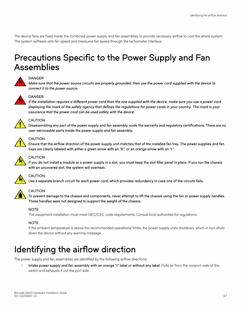
The device fans are fixed inside the combined power supply and fan assemblies to provide necessary airflow to cool the whole system.The system software sets fan speed and measures fan speed through the tachometer interface.
Precautions Specific to the Power Supply and FanAssemblies
DANGERMake sure that the power source circuits are properly grounded, then use the power cord supplied with the device toconnect it to the power source.
DANGERIf the installation requires a different power cord than the one supplied with the device, make sure you use a power corddisplaying the mark of the safety agency that defines the regulations for power cords in your country. The mark is yourassurance that the power cord can be used safely with the device.
CAUTIONDisassembling any part of the power supply and fan assembly voids the warranty and regulatory certifications. There are nouser-serviceable parts inside the power supply and fan assembly.
CAUTIONEnsure that the airflow direction of the power supply unit matches that of the installed fan tray. The power supplies and fantrays are clearly labeled with either a green arrow with an "E", or an orange arrow with an "I."
CAUTIONIf you do not install a module or a power supply in a slot, you must keep the slot filler panel in place. If you run the chassiswith an uncovered slot, the system will overheat.
CAUTIONUse a separate branch circuit for each power cord, which provides redundancy in case one of the circuits fails.
CAUTIONTo prevent damage to the chassis and components, never attempt to lift the chassis using the fan or power supply handles.These handles were not designed to support the weight of the chassis.
NOTEThe equipment installation must meet NEC/CEC code requirements. Consult local authorities for regulations.
NOTEIf the ambient temperature is above the recommended operational limits, the power supply units shutdown, which in turn shutsdown the device without any warning message.
Identifying the airflow directionThe power supply and fan assemblies are identified by the following airflow directions:
• Intake power supply and fan assembly with an orange "I" label or without any label: Pulls air from the nonport-side of theswitch and exhausts it out the port side.
Identifying the airflow direction
Brocade G620 Hardware Installation Guide53-1003990-13 67

– Nonport-side air intake– Port-side air exhaust– Back-to-front (nonport-side to port-side) airflow– Part numbers ending with -R
• Exhaust power supply and fan assembly with a green "E" label: Pulls air from the port side of the switch and exhausts it outthe nonport-side.
– Nonport-side air exhaust– Port-side air intake– Front-to-back (port-side to nonport-side) airflow– Part numbers ending with -F
Power Supply and Fan Assembly Status LEDSee the following table to interpret the power supply and fan assembly status LED during normal operation.
TABLE 15 Power Supply and Fan Assembly Status LED Patterns During Normal Operation
LED Color Description Action Required
No light The power supply and fan assembly is notreceiving power, or is off.
Verify that the power supply and fan assembly ison and seated and that the power cord isconnected to a functioning power source.
Steady green The power supply and fan assembly is operatingnormally.
No action is required.
Flashing green (for more than 5 seconds) The power supply and fan assembly is faulty forone of the following reasons:
• The assembly is switched off (flashingfor ~ 5 seconds, then off).
• The power cable is disconnected(flashing for ~ 5 seconds, then off).
• The power supply and fan assemblyhas failed.
NOTE: When the device is first powered on, thepower supply and fan assembly status LEDflashes until the POST has completed.
Try one of the following:
• Check the power cable connection.
• Verify that the assembly is poweredon.
• Replace the power supply and fanassembly.
Power Supply and Fan Assembly Unit Fault IndicatorsUse one of the following methods to determine the status of the power supply and fan assemblies:
• Check the power supply and fan assembly status LED. Refer to Power Supply and Fan Assembly Status LED on page 63 tointerpret the meaning of LED operation.
• In Web Tools, click the Power Status icon.
Power Supply and Fan Assembly Status LED
Brocade G620 Hardware Installation Guide68 53-1003990-13

• Enter the psShow command at the prompt to display the power supply and fan assembly status, as shown in the following
example:
Device:admin> psshowPower Supply #1 is OKPower Supply #2 is OK
Power Supply and Fan Assembly Task GuideYou can perform an easy set of steps to install or replace one or both assemblies. By default, both power supply and fan assemblies areinstalled in the device.
Installing an Additional Power Supply and Fan Assembly (Hot-Install)If your device is up and running with a single power supply and fan assembly and you want to install an additional power supply,complete the following steps.
1. Remove the existing filler panel.
2. Insert the new power supply and fan assembly.
3. Power on the power supply and an assembly.
4. Verify the power supply and fan assembly status LED.
Replacing a Power Supply and Fan Assembly (Hot-Swap)If your device is up and running with two power supply and fan assemblies, but one of them has failed, complete the following steps toreplace it.
1. Power down the old or failed power supply and fan assembly.
NOTESetting the power switch to the "O" position will not shut down the fans in the power supply and fan assembly.
2. Remove the old or failed power supply and fan assembly.
3. Insert the new power supply and fan assembly.
4. Power on the power supply and fan assembly.
5. Verify the power supply and fan assembly status LED.
NOTEThe power switch will not
Replacing Both Power Supply and Fan Assemblies (Cold-Swap)If your device is up and running with both power supply and fan assemblies, but you want to replace both of them, complete thefollowing steps.
1. Shut down the system using the sysShutdown command.
2. Power down both power supply and fan assemblies.
Power Supply and Fan Assembly Task Guide
Brocade G620 Hardware Installation Guide53-1003990-13 69

3. Remove the old/failed power supply and fan assemblies.
4. Insert the new power supply and fan assemblies.
5. Power on both power supply and fan assemblies.
6. Verify operation using the power supply and fan assembly status LEDs.
Time and Items RequiredInstalling or removing and replacing a power supply and fan assembly should require less than 5 minutes to complete.
The following items are required to replace a power supply and fan assembly:
• New power supply and fan assembly (must have the same airflow direction as the power supply and fan assembly beingreplaced)
• #1 Phillips-head screwdriver
Recording Power Supply and Fan Assembly CriticalInformationYou can use the following commands to record the power supply and fan assembly configuration and operation information:
• chassisshow• fanshow• historyshow• psshow• tempshow• sensorshow
Refer to the Brocade Fabric OS Command Reference for output examples and descriptions.
Removing a power supply and fan assemblyComplete the following steps to remove a faulty power supply and fan assembly.
Time and Items Required
Brocade G620 Hardware Installation Guide70 53-1003990-13

CAUTIONThe power supply switch must be in the off position when you insert the power supply into the chassis. Damage to theswitch can result if a live power supply is installed.
1. To leave the device in service while replacing a power supply and fan assembly, verify that the other power supply and fanassembly (the one not being replaced) has been powered on for at least four seconds and has a steady green LED.
FIGURE 32 AC power supply and fan assembly
1. Power supply and fan assembly handle 2. Captive screw
2. Power off the power supply to be replaced by flipping the AC power switch to the off position (the “O” symbol). The fans in theother power supply will automatically switch to high speed to maintain adequate cooling.
3. Unplug the power cord from the power supply and fan assembly that is being replaced.
4. Using a Phillips screwdriver, unscrew the captive screw.
5. Remove the power supply and fan assembly from the chassis by pulling the handle out and away from the chassis.
Inserting a new power supply and fan assemblyComplete the following steps to insert a new power supply and fan assembly into the chassis.
CAUTIONThe power supply switch must be in the off position when you insert the power supply into the chassis. Damage to theswitch can result if a live power supply is installed.
Inserting a new power supply and fan assembly
Brocade G620 Hardware Installation Guide53-1003990-13 71

The new power supply and fan assembly must have the same part number and airflow label (or lack thereof) as the power supply and fanassembly already installed.
1. To leave the device in service while installing a power supply and fan assembly, verify that the other power supply and fanassembly (the one already installed) has been powered on for at least four seconds and has a steady green LED.
2. Using a Phillips screwdriver, unscrew the captive screw of the filler panel that is located in the empty power supply and fanassembly slot.
3. Orient the new power supply and fan assembly with the captive screw on the right, as shown in the figure.
Do not force the installation. If the power supply and fan assembly does not slide in easily, ensure that it is correctly orientedbefore continuing.
CAUTIONCarefully follow the mechanical guides on each side of the power supply slot and make sure the power supply isproperly inserted in the guides. Never insert the power supply upside down.
FIGURE 33 Insert an AC power supply and fan assembly
1. The device
2. AC power supply and fan assembly
3. Captive screw
4. Gently push the power supply and fan assembly into the chassis until it is firmly seated.
5. Using the Phillips screwdriver, secure the power supply and fan assembly to the chassis by tightening the captive screw.
6. Plug the power cord into the power supply and fan assembly and power on the unit by flipping the PSU power switch to the onposition (the “I”symbol).
7. Verify that the LED on the new power supply and fan assembly displays a steady green light while the device is operating. If theLED is not a steady green, ensure that the power supply is securely installed and seated properly.
8. Optional: Enter psshow to display the PSU status. The power supply and fan assembly status can also be viewed using WebTools.
Inserting a new power supply and fan assembly
Brocade G620 Hardware Installation Guide72 53-1003990-13

Verifying the Operation of the Power Supply and FanAssembliesYou can use the following commands to verify that the power supply and fan assemblies are operational:
• errDump
• fanShow
• psShow
• switchShow
Refer to the Fabric OS Command Reference for output examples and descriptions.
Verifying the Operation of the Power Supply and Fan Assemblies
Brocade G620 Hardware Installation Guide53-1003990-13 73

Brocade G620 Technical SpecificationsThis document highlights the features and specifications for the Brocade G620 switch.
System specificationsSystem component Description
Enclosure 1U, port-side back-to-front exhaust airflow, power from back
Power inlet C14
Power supplies Dual, hot-swappable, redundant, AC input power supplies with integrated system cooling fans
Fans Three fans integrated in each power supply and fan assembly
Cooling Port side to the nonport-side of the switch (nonport-side exhaust) and nonport-side to the port side (port-sideexhaust)
System architecture Nonblocking shared memory switch
System processors Freescale T1022 CPU
Port-to-port latency <900 nanoseconds (including FEC) with no contention (destination port is free)
Fibre ChannelSystem component Description
Fibre Channel ports 48 SFP+ ports that support any combination of Short Wavelength (SWL) and Long Wavelength (LWL) orExtended Long Wavelength (ELWL) optical media.
4 QSFP ports that support 32-Gbps QSFP transceivers.
The SFP+ ports are capable of auto-negotiating to 4, 8, 16, or 32 Gbps speed depending on the SFP+ modeland the minimum supported speed of the optical transceiver at the other end of the link.
• 4-, 8-, and 16-Gbps performance is enabled by 16-Gbps SFP+ transceivers provided the other endof the connection is minimum of 4 Gbps speed.
• 8-, 16-, and 32-Gbps performance is enabled by 32-Gbps SFP+ transceivers provided the other endof the connection is minimum of 8 Gbps speed.
NOTE2-, 4- and 8-Gbps transceivers are not supported.
ANSI Fibre Channel protocol FC-PH (Fibre Channel Physical and Signaling Interface standard)
Modes of operation Fibre Channel Class 2 and Class 3
Fabric initialization Complies with FC-SW-3 Rev. 6.6
FCIP (IP over Fibre Channel) Complies with FC-IP 2.3 of FCA profile
Port Status Bicolor LED (amber/green)
Brocade G620 Hardware Installation Guide74 53-1003990-13

OtherSystem component Description
Serial console port One three-wire (Tx, Rx, Gnd) UART serial port
Ethernet management port One 1000/100/10 Mbps Ethernet port
USB port One external USB port
LEDsSystem component Description
System power LED One green system power status LED (upper) on the port side.
System status LED One bicolor (green/amber) system status LED (lower) on the port side.
Ethernet port link LED One status LED on the left of the RJ45 connector. Glows green for 1000 Mbps and amber for 100/10 Mbps.
Ethernet port activity LED One link activity LED on the right of the RJ45 connector.
Serial console port LED The serial console port LEDs remain off at all times, even when a cable is inserted and the link is active.
FC port status LED 64 bicolor (green/amber) port status LEDs. One for each SFP+ port and four for each QSFP port on the switch.
Power supply and fan assemblystatus LED
One green power supply and fan assembly status LED on each power supply and fan assembly on the nonport-side of the switch.
OtherSystem component Description
Serial cable RJ-45 console cable
RJ-45 to DB9 adapter RJ-45 to DB9 for console cable
RJ-45 connector Uses an RJ-45 connector for the serial port
Weight and physical dimensionsEmpty weight refers to the device with two power supply and fan assemblies installed but no SFP+ or QSFP transceivers.
Model Height Width Depth Weight (empty) Weight (fully loaded)
Brocade G620 switch 4.39 cm
1.73 inches
44.00 cm
17.32 inches
35.56 cm
14.00 inches
7.71 kg
17.00 lb
8.53 kg
18.80 lb
Environmental requirementsCondition Operational Non-operational
Ambient temperature 0°C to 40°C (32°F to 104°F) -25°C to 70°C (-13°F to 158°F)
Relative humidity (non-condensing)
10% to 85% at 40°C (104°F) 10% to 90% non-condensing
Environmental requirements
Brocade G620 Hardware Installation Guide53-1003990-13 75

Condition Operational Non-operational
Altitude (above sea level) 0 to 3000 m (9,842 feet) 0 to 12000 m (39,370 feet)
Shock 20.0 G, 6 ms, half-sine wave 33.0 G, 11 ms, half-sine wave, 3G Axis
Vibration 0.25G sine, 0.4grms random, 5 – 500Hz 5Hz at 0.5grms, 10-500Hz at 1.0grms (sine vibration);3-500Hz at 1.12grms (random vibration)
Airflow Maximum: 71.36 cmh (42 cfm)
Nominal: 59.47 cmh (35 cfm)
N/A
Heat dissipation Refer to the Power consumption table N/A
Operating noise Maximum: 65 dB N/A
Power supply specifications (per PSU)Power supplymodel
Maximumoutput powerrating (DC)
Input voltage Input line frequency Maximum inputcurrent
Input lineprotection
Maximum inrush current
XBR-G250WPSAC-F
250 W 100 – 240 VAC(nominal)
90 – 264 VAC (range)
50/60 Hz (nominal)
47 – 63 Hz (range)
3.5 A Line fused 50 A peak @ 240 VAC for <10ms, 10 ms - 150 ms, <15 Apeak.
50 A peak @ 240 VAC at coldstart for <10 ms.
15 A peak for cycles 10 ms -150 ms. <3.5 A peak for >150ms
XBR-G250WPSAC-R
250 W 100 – 240 VAC(nominal)
90 – 264 VAC (range)
50/60 Hz (nominal)
47 – 63 Hz (range)
3.5 A Line Fused 50 A peak @ 240 VAC for <10ms, 10 ms - 150 ms, <15 Apeak.
50 A peak @ 240 VAC at coldstart for <10 ms.
15 A peak for cycles 10 ms -150 ms. <3.5 A peak for >150ms
Power consumption (typical configuration)Model name @100 VAC
input@200 VACinput
@48 VDC input Minimum number ofpower supplies
Notes
Brocade G620switch
1.93 A
192 W
655 BTU/hr
0.97 A
190 W
649 BTU/hr
Not supported 1 (But, input current isfor 1 PSU. Watts andBTUs/hr are with 2PSUs).
Fully configured all ports with 25% trafficrate, fans at high speed, and input power +/-5% tolerance.
Power supply specifications (per PSU)
Brocade G620 Hardware Installation Guide76 53-1003990-13
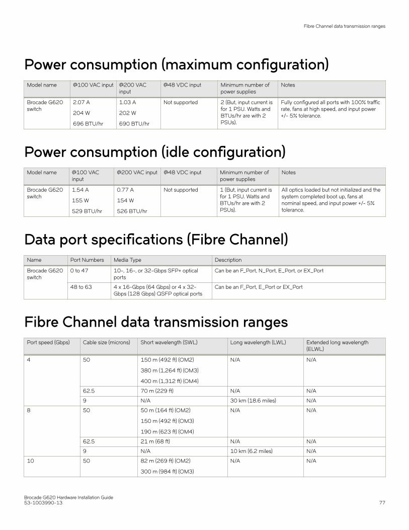
Power consumption (maximum configuration)Model name @100 VAC input @200 VAC
input@48 VDC input Minimum number of
power suppliesNotes
Brocade G620switch
2.07 A
204 W
696 BTU/hr
1.03 A
202 W
690 BTU/hr
Not supported 2 (But, input current isfor 1 PSU. Watts andBTUs/hr are with 2PSUs).
Fully configured all ports with 100% trafficrate, fans at high speed, and input power+/- 5% tolerance.
Power consumption (idle configuration)Model name @100 VAC
input@200 VAC input @48 VDC input Minimum number of
power suppliesNotes
Brocade G620switch
1.54 A
155 W
529 BTU/hr
0.77 A
154 W
526 BTU/hr
Not supported 1 (But, input current isfor 1 PSU. Watts andBTUs/hr are with 2PSUs).
All optics loaded but not initialized and thesystem completed boot up, fans atnominal speed, and input power +/- 5%tolerance.
Data port specifications (Fibre Channel)Name Port Numbers Media Type Description
Brocade G620switch
0 to 47 10-, 16-, or 32-Gbps SFP+ opticalports
Can be an F_Port, N_Port, E_Port, or EX_Port
48 to 63 4 x 16-Gbps (64 Gbps) or 4 x 32-Gbps (128 Gbps) QSFP optical ports
Can be an F_Port, E_Port or EX_Port
Fibre Channel data transmission rangesPort speed (Gbps) Cable size (microns) Short wavelength (SWL) Long wavelength (LWL) Extended long wavelength
(ELWL)
4 50 150 m (492 ft) (OM2)
380 m (1,264 ft) (OM3)
400 m (1,312 ft) (OM4)
N/A N/A
62.5 70 m (229 ft) N/A N/A
9 N/A 30 km (18.6 miles) N/A
8 50 50 m (164 ft) (OM2)
150 m (492 ft) (OM3)
190 m (623 ft) (OM4)
N/A N/A
62.5 21 m (68 ft) N/A N/A
9 N/A 10 km (6.2 miles) N/A
10 50 82 m (269 ft) (OM2)
300 m (984 ft) (OM3)
N/A N/A
Fibre Channel data transmission ranges
Brocade G620 Hardware Installation Guide53-1003990-13 77

Port speed (Gbps) Cable size (microns) Short wavelength (SWL) Long wavelength (LWL) Extended long wavelength(ELWL)
550 m (1,804 ft) (OM4)
62.5 33 m (108 ft) N/A N/A
9 N/A 10 km (6.2 miles) N/A
16 50 35 m (115 ft) (OM2)
100 m (328 ft) (OM3)
125 m (410 ft) (OM4)
N/A N/A
62.5 15 m (49 ft) N/A N/A
9 N/A 10 km (6.2 miles) N/A
32 50 70 m (230 ft) (OM3)
100 m (328 ft) (OM4)
N/A N/A
62.5 N/A N/A N/A
9 N/A 10 km (6.2 miles) N/A
Serial port specifications (pinout RJ-45)Pin Signal Description
1 Not supported N/A
2 Not supported N/A
3 UART1_RXD Receive data
4 GND Logic ground
5 GND Logic ground
6 UART2_TXD Transmit data
7 Not supported N/A
8 Not supported N/A
NOTEThese specifications are for connector on Brocade platform only.
Serial port specifications (protocol)Parameter Value
Baud 9600
Data bits 8
Parity None
Flow control None
Stop bits 1
Serial port specifications (pinout RJ-45)
Brocade G620 Hardware Installation Guide78 53-1003990-13

Memory specificationsMemory Type Size
Main Memory DDR3L SDRAM with 8-bit ECC, SORDIMM package, operating at1200 MT/s
2 GB, 64-bit
Boot Flash Parallel NOR flash embedded memory 8 MB
eUSB Module - 2 GB
Regulatory Compliance (EMC)• 2014/30/EU
• AS/NZS CISPR 55032 (Australia) (Class A)
• CISPR 32
• CNS 13438
• EN 300 386
• EN 55032/55024 (CE Mark) (Class A)
• EN 61000-3-2
• EN 61000-3-3
• FCC Part 15, Subpart B (Class A)
• GB 9254
• ICES-003 (Canada)
• KN 32
• KN 35
• TCVN 7189
• VCCI-32 (Japan)
Regulatory Compliance (Safety)• 2014/35/EU
• CNS 14336-1
• EN/UL 60825
• EN/UL/CSA/IEC 60950-1
• GB 4943.1
Regulatory Compliance (Environmental)• 2011/65/EU - Restriction of the use of certain hazardous substance in electrical and electronic equipment (EU RoHS).
• 2012/19/EU - Waste electrical and electronic equipment (EU WEEE).
• 94/62/EC - Packaging and packaging waste (EU).
• 2006/66/EC - Batteries and accumulators and waste batteries and accumulators (EU battery directive).
Regulatory Compliance (Environmental)
Brocade G620 Hardware Installation Guide53-1003990-13 79

• 1907/2006 of the European Parliament and of the Council of 18 December 2006 concerning the Registration, Evaluation,Authorisation and Restriction of Chemicals (EU REACH).
• Section 1502 of the Dodd-Frank Wall Street Reform and Consumer Protection Act of 2010 - U.S. Conflict Minerals.
• 30/2011/TT-BCT - Vietnam circular.
• SJ/T 11363-2006 Requirements for Concentration Limits for Certain Hazardous Substances in EIPs (China).
• SJ/T 11364-2006 Marking for the Control of Pollution Caused by EIPs (China).
Regulatory Compliance (Environmental)
Brocade G620 Hardware Installation Guide80 53-1003990-13

Regulatory Statements• BSMI Statement (Taiwan)...............................................................................................................................................................................81• Canadian Requirements..................................................................................................................................................................................81• CE Statement...................................................................................................................................................................................................... 81• China CCC Statement......................................................................................................................................................................................82• China ROHS........................................................................................................................................................................................................82• FCC Warning (U.S. Only)................................................................................................................................................................................ 82• Germany Statement......................................................................................................................................................................................... 83• KCC Statement (Republic of Korea)........................................................................................................................................................... 83• VCCI Statement..................................................................................................................................................................................................83• Taiwan ROHS certification.............................................................................................................................................................................84
BSMI Statement (Taiwan)
Warning:
This is Class A product. In a domestic environment, this product may cause radio interference, in which case the user may be required totake adequate measures.
Canadian RequirementsThis Class A digital apparatus meets all requirements of the Canadian Interference-Causing Equipment Regulations, ICES-003 Class A.
Cet appareil numérique de la classe A est conforme à la norme NMB-003 du Canada.
CE StatementATTENTIONThis is Class A product. In a domestic environment, this product may cause radio interference, in which case the user may berequired to take adequate measures.
The standards compliance label on this device contains the CE mark, which indicates that this system conforms to the provisions of thefollowing European Council directives, laws, and standards:
• Electromagnetic Compatibility (EMC) Directive 2014/30/EU
• Low Voltage Directive (LVD) 2014/35/EU
• EN 55032/EN 55024 (European Immunity Requirements)
– EN61000-3-2/JEIDA (European and Japanese Harmonics Spec)– EN61000-3-3
Brocade G620 Hardware Installation Guide53-1003990-13 81

China CCC Statement
China ROHSRefer to the latest revision of the China ROHS document (P/N 53‐1000428‐xx) which ships with the product.
FCC Warning (U.S. Only)This equipment has been tested and complies with the limits for a Class A computing device pursuant to Part 15 of the FCC rules.These limits are designed to provide reasonable protection against harmful interference when the equipment is operated in a commercialenvironment.
China CCC Statement
Brocade G620 Hardware Installation Guide82 53-1003990-13

This equipment generates, uses, and can radiate radio frequency energy, and if not installed and used in accordance with the instructionmanual, might cause harmful interference to radio communications. Operation of this equipment in a residential area is likely to causeharmful interference, in which case the user will be required to correct the interference at the user’s own expense.
Germany StatementMachine noise information regulation - 3. GPSGV, the highest sound pressure level value is 70.0 dB(A) in accordance with EN ISO7779.
Maschinenlärminformations-Verordnung - 3. GPSGV, der höchste Schalldruckpegel beträgt 70.0 dB(A) gemäss EN ISO 7779.
KCC Statement (Republic of Korea)
Class A device (Broadcasting Communication Device for Office Use): This device obtained EMC registration for office use (Class A), andmay be used in places other than home. Sellers and/or users need to take note of this.
VCCI Statement
This is a Class A product based on the standard of the Voluntary Control Council for Interference by Information Technology Equipment(VCCI). If this equipment is used in a domestic environment, radio disturbance might arise. When such trouble occurs, the user might berequired to take corrective actions.
VCCI Statement
Brocade G620 Hardware Installation Guide53-1003990-13 83

Taiwan ROHS certification
Taiwan ROHS certification
Brocade G620 Hardware Installation Guide84 53-1003990-13

Cautions and Danger Notices• Danger Notices...................................................................................................................................................................................................85• Cautions.................................................................................................................................................................................................................87
Danger NoticesA Danger statement indicates conditions or situations that can be potentially lethal or extremely hazardous to you. Safety labels are alsoattached directly to products to warn of these conditions or situations.
Ein Gefahrenhinweis warnt vor Bedingungen oder Situationen die tödlich sein können oder Sie extrem gefährden können.Sicherheitsetiketten sind direkt auf den jeweiligen Produkten angebracht um vor diesen Bedingungen und Situationen zu warnen.
Un énoncé de danger indique des conditions ou des situations potentiellement mortelles ou extrêmement dangereuses. Des étiquettesde sécurité sont posées directement sur le produit et vous avertissent de ces conditions ou situations.
Una advertencia de peligro indica condiciones o situaciones que pueden resultar potencialmente letales o extremadamente peligrosas.También habrá etiquetas de seguridad pegadas directamente sobre los productos para advertir de estas condiciones o situaciones.
General DangersDANGERThe procedures in this manual are for qualified service personnel.
GEFAHR Die Vorgehensweisen in diesem Handbuch sind für qualifiziertes Servicepersonal bestimmt.
DANGER Les procédures décrites dans ce manuel doivent être effectuées par un personnel de maintenance qualifié.
PELIGRO Los procedimientos de este manual deben llevarlos a cabo técnicos cualificados.
DANGERBe careful not to accidently insert your fingers into the fan tray while removing it from the chassis. The fan may still bespinning at a high speed.
GEFAHR Die Finger dürfen nicht versehentlich in das Ventilatorblech gesteckt werden, wenn dieses vom Gehäuse abgenommen wird.Der Ventilator kann sich unter Umständen noch mit hoher Geschwindigkeit drehen.
DANGER Faites attention de ne pas insérer vos doigts accidentellement dans le boîtier du ventilateur lorsque vous le retirez du châssis.Il est possible que le ventilateur tourne encore à grande vitesse.
PELIGRO Procure no insertar los dedos accidentalmente en la bandeja del ventilador cuando esté desmontando el chasis. El ventiladorpodría estar girando a gran velocidad.
Electrical DangersDANGERFor safety reasons, the ESD wrist strap should contain a series 1 megaohm resistor.
GEFAHR Aus Sicherheitsgründen sollte ein EGB-Armband zum Schutz von elektronischen gefährdeten Bauelementen mit einem 1Megaohm-Reihenwiderstand ausgestattet sein.
DANGER Pour des raisons de sécurité, la dragonne ESD doit contenir une résistance de série 1 méga ohm.
Brocade G620 Hardware Installation Guide53-1003990-13 85
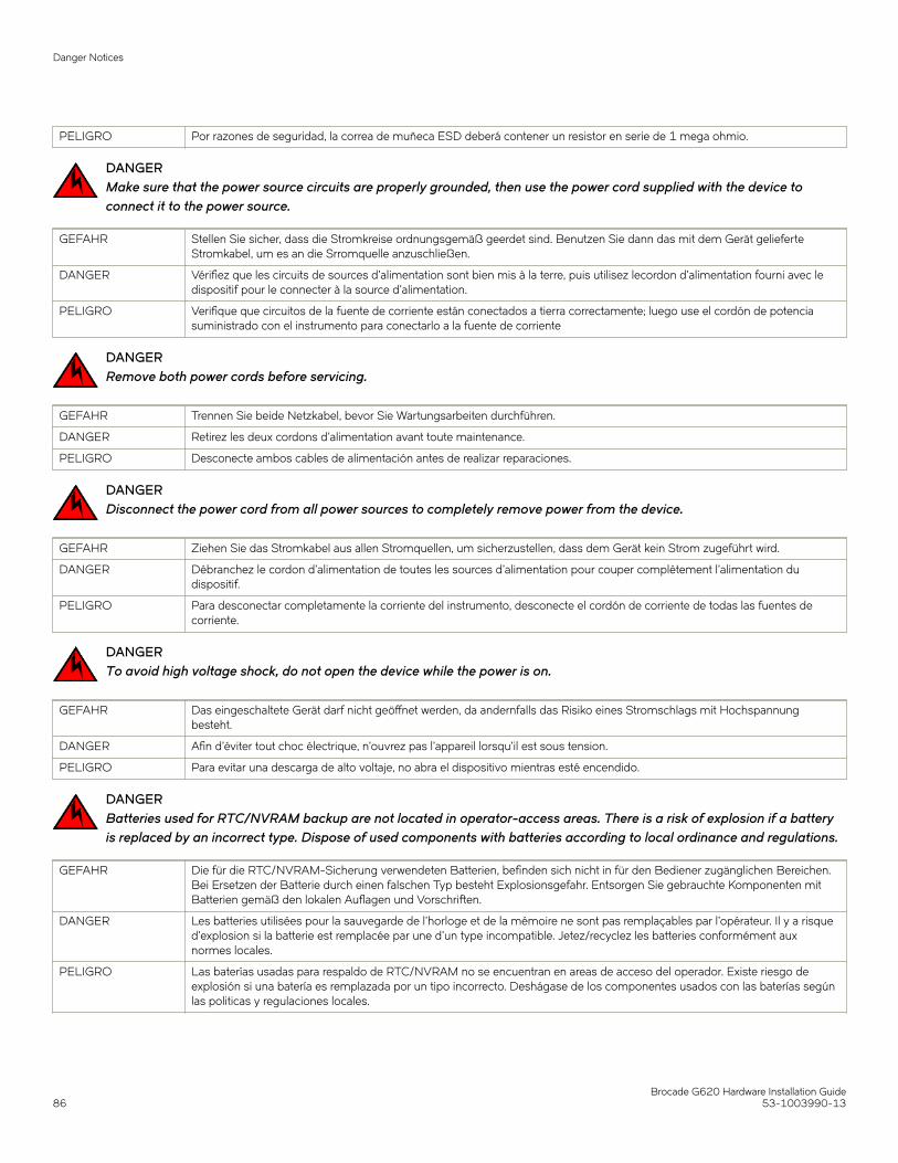
PELIGRO Por razones de seguridad, la correa de muñeca ESD deberá contener un resistor en serie de 1 mega ohmio.
DANGERMake sure that the power source circuits are properly grounded, then use the power cord supplied with the device toconnect it to the power source.
GEFAHR Stellen Sie sicher, dass die Stromkreise ordnungsgemäß geerdet sind. Benutzen Sie dann das mit dem Gerät gelieferteStromkabel, um es an die Srromquelle anzuschließen.
DANGER Vérifiez que les circuits de sources d'alimentation sont bien mis à la terre, puis utilisez lecordon d'alimentation fourni avec ledispositif pour le connecter à la source d'alimentation.
PELIGRO Verifique que circuitos de la fuente de corriente están conectados a tierra correctamente; luego use el cordón de potenciasuministrado con el instrumento para conectarlo a la fuente de corriente
DANGERRemove both power cords before servicing.
GEFAHR Trennen Sie beide Netzkabel, bevor Sie Wartungsarbeiten durchführen.
DANGER Retirez les deux cordons d'alimentation avant toute maintenance.
PELIGRO Desconecte ambos cables de alimentación antes de realizar reparaciones.
DANGERDisconnect the power cord from all power sources to completely remove power from the device.
GEFAHR Ziehen Sie das Stromkabel aus allen Stromquellen, um sicherzustellen, dass dem Gerät kein Strom zugeführt wird.
DANGER Débranchez le cordon d'alimentation de toutes les sources d'alimentation pour couper complètement l'alimentation dudispositif.
PELIGRO Para desconectar completamente la corriente del instrumento, desconecte el cordón de corriente de todas las fuentes decorriente.
DANGERTo avoid high voltage shock, do not open the device while the power is on.
GEFAHR Das eingeschaltete Gerät darf nicht geöffnet werden, da andernfalls das Risiko eines Stromschlags mit Hochspannungbesteht.
DANGER Afin d'éviter tout choc électrique, n'ouvrez pas l'appareil lorsqu'il est sous tension.
PELIGRO Para evitar una descarga de alto voltaje, no abra el dispositivo mientras esté encendido.
DANGERBatteries used for RTC/NVRAM backup are not located in operator-access areas. There is a risk of explosion if a batteryis replaced by an incorrect type. Dispose of used components with batteries according to local ordinance and regulations.
GEFAHR Die für die RTC/NVRAM-Sicherung verwendeten Batterien, befinden sich nicht in für den Bediener zugänglichen Bereichen.Bei Ersetzen der Batterie durch einen falschen Typ besteht Explosionsgefahr. Entsorgen Sie gebrauchte Komponenten mitBatterien gemäß den lokalen Auflagen und Vorschriften.
DANGER Les batteries utilisées pour la sauvegarde de l'horloge et de la mémoire ne sont pas remplaçables par l'opérateur. Il y a risqued'explosion si la batterie est remplacée par une d'un type incompatible. Jetez/recyclez les batteries conformément auxnormes locales.
PELIGRO Las baterías usadas para respaldo de RTC/NVRAM no se encuentran en areas de acceso del operador. Existe riesgo deexplosión si una batería es remplazada por un tipo incorrecto. Deshágase de los componentes usados con las baterías segúnlas politicas y regulaciones locales.
Danger Notices
Brocade G620 Hardware Installation Guide86 53-1003990-13
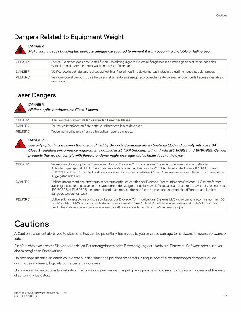
Dangers Related to Equipment WeightDANGERMake sure the rack housing the device is adequately secured to prevent it from becoming unstable or falling over.
GEFAHR Stellen Sie sicher, dass das Gestell für die Unterbringung des Geräts auf angemessene Weise gesichert ist, so dass dasGestell oder der Schrank nicht wackeln oder umfallen kann.
DANGER Vérifiez que le bâti abritant le dispositif est bien fixé afin qu'il ne devienne pas instable ou qu'il ne risque pas de tomber.
PELIGRO Verifique que el bastidor que alberga el instrumento está asegurado correctamente para evitar que pueda hacerse inestable oque caiga.
Laser DangersDANGERAll fiber-optic interfaces use Class 1 lasers.
GEFAHR Alle Glasfaser-Schnittstellen verwenden Laser der Klasse 1.
DANGER Toutes les interfaces en fibre optique utilisent des lasers de classe 1.
PELIGRO Todas las interfaces de fibra óptica utilizan láser de clase 1.
DANGERUse only optical transceivers that are qualified by Brocade Communications Systems LLC and comply with the FDAClass 1 radiation performance requirements defined in 21 CFR Subchapter I, and with IEC 60825 and EN60825. Opticalproducts that do not comply with these standards might emit light that is hazardous to the eyes.
GEFAHR Verwenden Sie nur optische Transceiver, die von Brocade Communications Systems zugelassen sind und die dieAnforderungen gemäß FDA Class 1 Radiation Performance Standards in 21 CFR, Unterkapitel I, sowie IEC 60825 undEN60825 erfüllen. Optische Produkte, die diese Normen nicht erfüllen, können Strahlen aussenden, die für das menschlicheAuge gefährlich sind.
DANGER Utilisez uniquement des émetteurs-récepteurs optiques certifiés par Brocade Communications Systems LLC et conformesaux exigences sur la puissance de rayonnement de catégorie 1 de la FDA définies au sous-chapitre 21 CFR I et à les normesIEC 60825 et EN60825. Les produits optiques non-conformes à ces normes sont susceptibles d’émettre une lumièredangereuse pour les yeux.
PELIGRO Utilice sólo transceptores ópticos aprobados por Brocade Communications Systems LLC y que cumplan con las normas IEC60825 y EN60825, y con los estándares de rendimiento Clase 1 de FDA definidos en el subcapítulo I de 21 CFR. Losproductos ópticos que no cumplan con estos estándares pueden emitir luz dañina para los ojos.
CautionsA Caution statement alerts you to situations that can be potentially hazardous to you or cause damage to hardware, firmware, software, ordata.
Ein Vorsichthinweis warnt Sie vor potenziellen Personengefahren oder Beschädigung der Hardware, Firmware, Software oder auch voreinem möglichen Datenverlust
Un message de mise en garde vous alerte sur des situations pouvant présenter un risque potentiel de dommages corporels ou dedommages matériels, logiciels ou de perte de données.
Un mensaje de precaución le alerta de situaciones que pueden resultar peligrosas para usted o causar daños en el hardware, el firmware,el software o los datos.
Cautions
Brocade G620 Hardware Installation Guide53-1003990-13 87

General CautionsCAUTIONChanges or modifications made to this device that are not expressly approved by the party responsible for compliancecould void the user's authority to operate the equipment.
VORSICHT Falls dieses Gerät verändert oder modifiziert wird, ohne die ausdrückliche Genehmigung der für die Einhaltung derAnforderungen verantwortlichen Partei einzuholen, kann dem Benutzer der weitere Betrieb des Gerätes untersagt werden.
MISE EN GARDE Les éventuelles modifications apportées à cet équipement sans avoir été expressément approuvées par la partie responsabled'en évaluer la conformité sont susceptibles d'annuler le droit de l'utilisateur à utiliser cet équipement.
PRECAUCIÓN Si se realizan cambios o modificaciones en este dispositivo sin la autorización expresa de la parte responsable delcumplimiento de las normas, la licencia del usuario para operar este equipo puede quedar anulada.
CAUTIONDo not install the device in an environment where the operating ambient temperature might exceed 40°C (104°F).
VORSICHT Das Gerät darf nicht in einer Umgebung mit einer Umgebungsbetriebstemperatur von über 40°C (104°F) installiert werden.
MISE EN GARDE N'installez pas le dispositif dans un environnement où la température d'exploitation ambiante risque de dépasser 40°C(104°F).
PRECAUCIÓN No instale el instrumento en un entorno en el que la temperatura ambiente de operación pueda exceder los 40°C (104°F).
CAUTIONMake sure the airflow around the front, and back of the device is not restricted.
VORSICHT Stellen Sie sicher, dass an der Vorderseite, den Seiten und an der Rückseite der Luftstrom nicht behindert wird.
MISE EN GARDE Vérifiez que rien ne restreint la circulation d'air devant, derrière et sur les côtés du dispositif et qu'elle peut se faire librement.
PRECAUCIÓN Asegúrese de que el flujo de aire en las inmediaciones de las partes anterior, laterales y posterior del instrumento no estérestringido.
Electrical CautionsCAUTIONBefore plugging a cable into any port, be sure to discharge the voltage stored on the cable by touching the electricalcontacts to ground surface.
VORSICHT Bevor Sie ein Kabel in einen Anschluss einstecken, entladen Sie jegliche im Kabel vorhandene elektrische Spannung, indemSie mit den elektrischen Kontakten eine geerdete Oberfläche berühren.
MISE EN GARDE Avant de brancher un câble à un port, assurez-vous de décharger la tension du câble en reliant les contacts électriques à laterre.
PRECAUCIÓN Antes de conectar un cable en cualquier puerto, asegúrese de descargar la tensión acumulada en el cable tocando lasuperficie de conexión a tierra con los contactos eléctricos.
CAUTIONStatic electricity can damage the chassis and other electronic devices. To avoid damage, keep static-sensitive devices intheir static-protective packages until you are ready to install them.
VORSICHT Statische Elektrizität kann das System und andere elektronische Geräte beschädigen. Um Schäden zu vermeiden, entnehmenSie elektrostatisch empfindliche Geräte erst aus deren antistatischer Schutzhülle, wenn Sie bereit für den Einbau sind.
MISE EN GARDE L'électricité statique peut endommager le châssis et les autres appareils électroniques. Pour éviter tout dommage, conservezles appareils sensibles à l'électricité statique dans leur emballage protecteur tant qu'ils n'ont pas été installés.
Cautions
Brocade G620 Hardware Installation Guide88 53-1003990-13

PRECAUCIÓN La electricidad estática puede dañar el chasis y otros dispositivos electrónicos. A fin de impedir que se produzcan daños,conserve los dispositivos susceptibles de dañarse con la electricidad estática dentro de los paquetes protectores hasta queesté listo para instalarlos.
CAUTIONIf you do not install a module or a power supply in a slot, you must keep the slot filler panel in place. If you run the chassiswith an uncovered slot, the system will overheat.
VORSICHT Falls kein Modul oder Netzteil im Steckplatz installiert wird, muss die Steckplatztafel angebracht werden. Wenn ein Steckplatznicht abgedeckt wird, läuft das System heiß.
MISE EN GARDE Si vous n’installez pas de module ou de bloc d'alimentation dans un slot, vous devez laisser le panneau du slot en place. Sivous faites fonctionner le châssis avec un slot découvert, le système surchauffera.
PRECAUCIÓN Si no instala un módulo o un fuente de alimentación en la ranura, deberá mantener el panel de ranuras en su lugar. Si pone enfuncionamiento el chasis con una ranura descubierta, el sistema sufrirá sobrecalentamiento.
CAUTIONCarefully follow the mechanical guides on each side of the power supply slot and make sure the power supply is properlyinserted in the guides. Never insert the power supply upside down.
VORSICHT Beachten Sie mechanischen Führungen an jeder Seite des Netzteils, das ordnungegemäß in die Führungen gesteckt werdenmuss. Das Netzteil darf niemals umgedreht eingesteckt werden.
MISE EN GARDE Suivez attentivement les repères mécaniques de chaque côté du slot du bloc d'alimentation et assurez-vous que le blocd'alimentation est bien inséré dans les repères. N'insérez jamais le bloc d'alimentation à l'envers.
PRECAUCIÓN Siga cuidadosamente las guías mecánicas de cada lado de la ranura del suministro de energía y verifique que el suministro deenergía está insertado correctamente en las guías. No inserte nunca el suministro de energía de manera invertida.
CAUTIONThe power supply switch must be in the off position when you insert the power supply into the chassis. Damage to theswitch can result if a live power supply is installed.
VORSICHT Der Schalter des Netzteils muss in der Stellung „Aus“ stehen, wenn das Netzteil in das Gehäuse eingesetzt wird. Wenn einspannungsführendes Netzteil (Schalterstellung "Ein") eingebaut wird, kann dies zu Beschädigungen am Switch führen.
MISE EN GARDE Le commutateur d'alimentation doit être en position d'arrêt lorsque vous insérez la source d'alimentation dans le châssis. Siune source d'alimentation sous tension est installée, des dommages peuvent être causés.
PRECAUCIÓN El interruptor de la fuente de alimentación debe estar en la posición de apagado en el momento de introducirla en el chasis. Elconmutador puede resultar dañado si se instala una fuente de alimentación activa.
Cautions
Brocade G620 Hardware Installation Guide53-1003990-13 89