
BroadWeigh User Manual€¦ · Configuration ... T24-BSue ... Mantracourt Electronics Limited...
110
BroadWeigh User Manual mantracourt.com BroadWeigh Dynamic Wireless Load Monitoring
Transcript of BroadWeigh User Manual€¦ · Configuration ... T24-BSue ... Mantracourt Electronics Limited...

BroadWeigh User Manual
mantracourt.com
BroadWeigh Dynamic Wireless Load Monitoring
Mantracourt Electronics Limited BroadWeigh User Manual 1
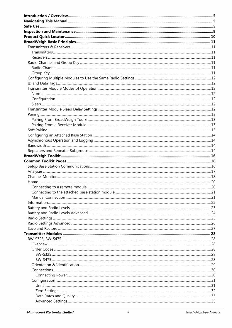
Introduction / Overview .............................................................................................................................................5 Navigating This Manual .............................................................................................................................................5 Safe Use ........................................................................................................................................................................5 Inspection and Maintenance .....................................................................................................................................9 Product Quick Locator ............................................................................................................................................. 10 BroadWeigh Basic Principles .................................................................................................................................. 11
Transmitters & Receivers ...................................................................................................................................................................... 11 Transmitters ........................................................................................................................................................................................... 11 Receivers ................................................................................................................................................................................................. 11
Radio Channel and Group Key ........................................................................................................................................................... 11 Radio Channel ...................................................................................................................................................................................... 11 Group Key ............................................................................................................................................................................................... 11
Configuring Multiple Modules to Use the Same Radio Settings .......................................................................................... 12 ID and Data Tags ...................................................................................................................................................................................... 12 Transmitter Module Modes of Operation ...................................................................................................................................... 12
Normal ..................................................................................................................................................................................................... 12 Configuration ........................................................................................................................................................................................ 12 Sleep ......................................................................................................................................................................................................... 12
Transmitter Module Sleep Delay Settings ...................................................................................................................................... 12 Pairing .......................................................................................................................................................................................................... 13
Pairing From BroadWeigh Toolkit ................................................................................................................................................ 13 Pairing From a Receiver Module ................................................................................................................................................... 13
Soft Pairing ................................................................................................................................................................................................. 13 Configuring an Attached Base Station ............................................................................................................................................ 14 Asynchronous Operation and Logging ........................................................................................................................................... 14 Bandwidth ................................................................................................................................................................................................... 14 Repeaters and Repeater Subgroups ................................................................................................................................................ 14
BroadWeigh Toolkit ................................................................................................................................................. 16 Common Toolkit Pages ........................................................................................................................................... 16
Setup Base Station Communications ............................................................................................................................................... 16 Analyser ....................................................................................................................................................................................................... 17 Channel Monitor ...................................................................................................................................................................................... 18 Home ............................................................................................................................................................................................................ 20
Connecting to a remote module ................................................................................................................................................... 20 Connecting to the attached base station module ................................................................................................................. 21 Manual Connection ............................................................................................................................................................................ 21
Information ................................................................................................................................................................................................. 22 Battery and Radio Levels ....................................................................................................................................................................... 23 Battery and Radio Levels Advanced ................................................................................................................................................. 24 Radio Settings ........................................................................................................................................................................................... 25 Radio Settings Advanced ...................................................................................................................................................................... 26 Save and Restore ..................................................................................................................................................................................... 27
Transmitter Modules ............................................................................................................................................... 28 BW-S325, BW-S475 ................................................................................................................................................................................. 28
Overview ................................................................................................................................................................................................. 28 Order Codes .......................................................................................................................................................................................... 28
BW-S325 ............................................................................................................................................................................................. 28 BW-S475 ............................................................................................................................................................................................. 28
Orientation & Identification ............................................................................................................................................................ 29 Connections ........................................................................................................................................................................................... 30
Connecting Power. ......................................................................................................................................................................... 30 Configuration ........................................................................................................................................................................................ 31
Units ..................................................................................................................................................................................................... 31 Zero Settings .................................................................................................................................................................................... 32 Data Rates and Quality ................................................................................................................................................................. 33 Advanced Settings.......................................................................................................................................................................... 35

Mantracourt Electronics Limited BroadWeigh User Manual 2
Enclosure & Mounting ...................................................................................................................................................................... 36 Dimensions ........................................................................................................................................................................................ 36
BW-S325 BroadWeigh Shackle 3.25T dimensions ........................................................................................................ 36 BW-S475 BroadWeigh Shackle 4.75T dimensions ........................................................................................................ 36
Opening the Case ........................................................................................................................................................................... 37 LED Indicator .................................................................................................................................................................................... 37
Specification .......................................................................................................................................................................................... 38 Radio Range ...................................................................................................................................................................................... 38
BW-WSS ....................................................................................................................................................................................................... 39 Overview ................................................................................................................................................................................................. 39 Order Codes .......................................................................................................................................................................................... 39
BW-WSS ............................................................................................................................................................................................. 39 Connections ........................................................................................................................................................................................... 40
Power .............................................................................................................................................................................................. 40 Configuration ........................................................................................................................................................................................ 41
Data Rates and Quality ................................................................................................................................................................. 41 Units ..................................................................................................................................................................................................... 43 Advanced Settings.......................................................................................................................................................................... 44
Enclosure & Mounting ...................................................................................................................................................................... 45 Antennas ................................................................................................................................................................................................. 45 Specification .......................................................................................................................................................................................... 46
Radio Range ...................................................................................................................................................................................... 46 Receiver Modules ..................................................................................................................................................... 47
BW-HR .......................................................................................................................................................................................................... 47 Overview ................................................................................................................................................................................................. 47 Order Codes .......................................................................................................................................................................................... 47
BW-HR................................................................................................................................................................................................. 47 Connections ........................................................................................................................................................................................... 48
Power ................................................................................................................................................................................................... 48 Operation ............................................................................................................................................................................................... 49
View readings ................................................................................................................................................................................... 49 Keys ...................................................................................................................................................................................................... 49 Indicators ........................................................................................................................................................................................... 49 Errors .................................................................................................................................................................................................... 50 Special Modes .................................................................................................................................................................................. 50
Configuration ........................................................................................................................................................................................ 52 Display Format ................................................................................................................................................................................. 52 Settings ............................................................................................................................................................................................... 54
Enclosure & Mounting ...................................................................................................................................................................... 55 Antennas ................................................................................................................................................................................................. 55 Specification .......................................................................................................................................................................................... 56
Radio Range ...................................................................................................................................................................................... 56 BW-RM1 ...................................................................................................................................................................................................... 57
Overview ................................................................................................................................................................................................. 57 Order Codes .......................................................................................................................................................................................... 57
BW-RM1 ............................................................................................................................................................................................. 57 Connections ........................................................................................................................................................................................... 58
Power ................................................................................................................................................................................................... 58 Connections & Indicators ............................................................................................................................................................ 58 LEDs ...................................................................................................................................................................................................... 58 Inputs ................................................................................................................................................................................................... 58
Operation ............................................................................................................................................................................................... 59 Configuration ........................................................................................................................................................................................ 61
Input Settings ................................................................................................................................................................................... 61 Relay Settings ................................................................................................................................................................................... 62
Operation and Hysteresis Settings ...................................................................................................................................... 63

Mantracourt Electronics Limited BroadWeigh User Manual 3
Relay Settings Advanced ............................................................................................................................................................. 64 Alarm Settings .................................................................................................................................................................................. 65
Enclosure & Mounting ...................................................................................................................................................................... 66 Antennas ................................................................................................................................................................................................. 66 Specification .......................................................................................................................................................................................... 67
Radio Range ...................................................................................................................................................................................... 67 Base Stations & Repeater Modules ....................................................................................................................... 68
BW-BSue, BW-BSd ................................................................................................................................................................................... 68 Overview ................................................................................................................................................................................................. 68 Order Codes .......................................................................................................................................................................................... 68
BW-BSue ............................................................................................................................................................................................ 68 BW-BSd ............................................................................................................................................................................................... 68
Connections ........................................................................................................................................................................................... 68 Configuration ........................................................................................................................................................................................ 69
Home ................................................................................................................................................................................................... 69 Radio Settings .................................................................................................................................................................................. 70 Advanced Settings.......................................................................................................................................................................... 71
Enclosure & Mounting ...................................................................................................................................................................... 72 T24-BSue ............................................................................................................................................................................................ 72 T24-BSd .............................................................................................................................................................................................. 72
Antennas ................................................................................................................................................................................................. 72 Specification .......................................................................................................................................................................................... 73
Radio Range ...................................................................................................................................................................................... 73 BW-AR .......................................................................................................................................................................................................... 74
Overview ................................................................................................................................................................................................. 74 Order Codes .......................................................................................................................................................................................... 74
BW-AR ................................................................................................................................................................................................. 74 Connections ........................................................................................................................................................................................... 75
Power ................................................................................................................................................................................................... 75 Power Options ............................................................................................................................................................................. 75
Permanently Powered ......................................................................................................................................................... 75 Battery Powered ..................................................................................................................................................................... 75
Getting Started ................................................................................................................................................................................ 76 Increase Range ............................................................................................................................................................................ 76 Span Obstacles ............................................................................................................................................................................ 77 Combined Solutions ................................................................................................................................................................. 78 Considerations ............................................................................................................................................................................ 79
Configuration ................................................................................................................................................................................... 80 Settings .......................................................................................................................................................................................... 80
Enclosure & Mounting ...................................................................................................................................................................... 82 Antennas ................................................................................................................................................................................................. 82
Radio Range ...................................................................................................................................................................................... 82 Specification .......................................................................................................................................................................................... 83
Radio Range ...................................................................................................................................................................................... 83 Power Supply Modules............................................................................................................................................ 84
PP1 & SP1 ................................................................................................................................................................................................... 84 Overview ................................................................................................................................................................................................. 84 Order Codes .......................................................................................................................................................................................... 84
PP1 ........................................................................................................................................................................................................ 84 SP1 ........................................................................................................................................................................................................ 84
Getting Started ..................................................................................................................................................................................... 85 Power Pack 1 Connections .......................................................................................................................................................... 85 Installation ......................................................................................................................................................................................... 85
Connecting Power Pack 1 ....................................................................................................................................................... 85 Solar Panel Orientation ............................................................................................................................................................ 86
Operation ........................................................................................................................................................................................... 87

Mantracourt Electronics Limited BroadWeigh User Manual 4
Dimensions & Weight ....................................................................................................................................................................... 88 Specifications ........................................................................................................................................................................................ 89
Appendices ................................................................................................................................................................ 90 Appendix A - Enclosures ....................................................................................................................................................................... 90
ACM Type ............................................................................................................................................................................................... 90 Dimensions ........................................................................................................................................................................................ 90 Opening the Case ........................................................................................................................................................................... 90 Mounting Information .................................................................................................................................................................. 90 Antenna Position............................................................................................................................................................................. 90 Environmental Protection ............................................................................................................................................................ 91
ACMi Type .............................................................................................................................................................................................. 92 Dimensions ........................................................................................................................................................................................ 92 Opening the Case ........................................................................................................................................................................... 92 Mounting Information .................................................................................................................................................................. 92 Antenna Position............................................................................................................................................................................. 92 Environmental Protection ............................................................................................................................................................ 92
Handheld Type ..................................................................................................................................................................................... 94 Dimensions ........................................................................................................................................................................................ 94 Opening the Case ........................................................................................................................................................................... 94 Mounting Information .................................................................................................................................................................. 95 Antenna Position............................................................................................................................................................................. 95 Environmental Protection ............................................................................................................................................................ 95
Dongle Type .......................................................................................................................................................................................... 96 Dimensions ........................................................................................................................................................................................ 96 Opening the Case ........................................................................................................................................................................... 96 Mounting Information .................................................................................................................................................................. 96 Antenna Position............................................................................................................................................................................. 96 Environmental Protection ............................................................................................................................................................ 96
Appendix B – Radio Range ................................................................................................................................................................... 97 Overview ................................................................................................................................................................................................. 97 Range ....................................................................................................................................................................................................... 97
Appendix C - Radio Specification ...................................................................................................................................................... 98 Appendix D – Intentionally Empty .................................................................................................................................................... 99 Appendix E – Approval Statements ................................................................................................................................................ 100
CE ............................................................................................................................................................................................................. 100 IC .............................................................................................................................................................................................................. 101 FCC .......................................................................................................................................................................................................... 102
Appendix F - OEM / Reseller Marking and Documentation Requirements ................................................................... 103 CE ............................................................................................................................................................................................................. 103 IC .............................................................................................................................................................................................................. 104 FCC .......................................................................................................................................................................................................... 105 Appendix G - Worldwide Regional Approvals ....................................................................................................................... 106 Important Note .................................................................................................................................................................................. 106
Appendix H - Declaration of Conformity ..................................................................................................................................... 107 Appendix I - Warranty .......................................................................................................................................................................... 108

Mantracourt Electronics Limited BroadWeigh User Manual 5
Introduction / Overview BroadWeigh is a portable modular wireless weighing system offering real-time load monitoring for a wide variety
of rigging applications without the need for cabling.
BroadWeigh enables users to know precise loads on any given point thereby ensuring structures and rigging
points are balanced and within safe working loads.
A user-friendly wireless Handheld Telemetry Display provides load monitoring of any BroadWeigh Shackle.
In addition a PC interface can be used to view and log multiple inputs on a single screen via the use of the
BroadWeigh Log100 Software and USB Base Station.
Navigating This Manual When viewing this PDF manual the following tips will help you navigate.
Viewing bookmarks ( or ) to the left of the page, in the PDF viewer, will allow easy navigation to the relevant
chapters of this manual. Alt-left arrow is a useful shortcut back to the last page viewed after a hyperlink is clicked.
Hyperlinks are coloured orange and are underlined.
Safe Use Designed to aid rigging professionals on a daily basis, the BroadWeigh wireless Crosby load cell shackles offer
simple, real-time, effective and accurate load monitoring. It allows users to know the precise loads on any given
rigging point, guy wire or hoist in a rigging system. This valuable data enables the rigger to safely distribute
weight for indeterminate loads, roof structures and mother-grids as well as indicate alarms to avoid overload
situations.
The BroadWeigh Shackle is a Crosby safety bow shackle with load pin and integrated electronics which features
the following:
Available in 4 ¾ tonne or 3 ¼ tonne WLL options
Up to 800 m line of sight wireless transmission range
IP67
5:1 safety factor
Low rigging profile of 130 mm
2000 hr battery life at transmission 1 per second
Sleep function to preserve battery life when not needed
Accuracy of ±1% of current load or 25 kg, whichever is the greater value
Shackles must be correctly selected for the specific application required. As well as safe working load, physical
size and fitment with other components needs to be considered.
Mantracourt Electronics Limited BroadWeigh User Manual 6
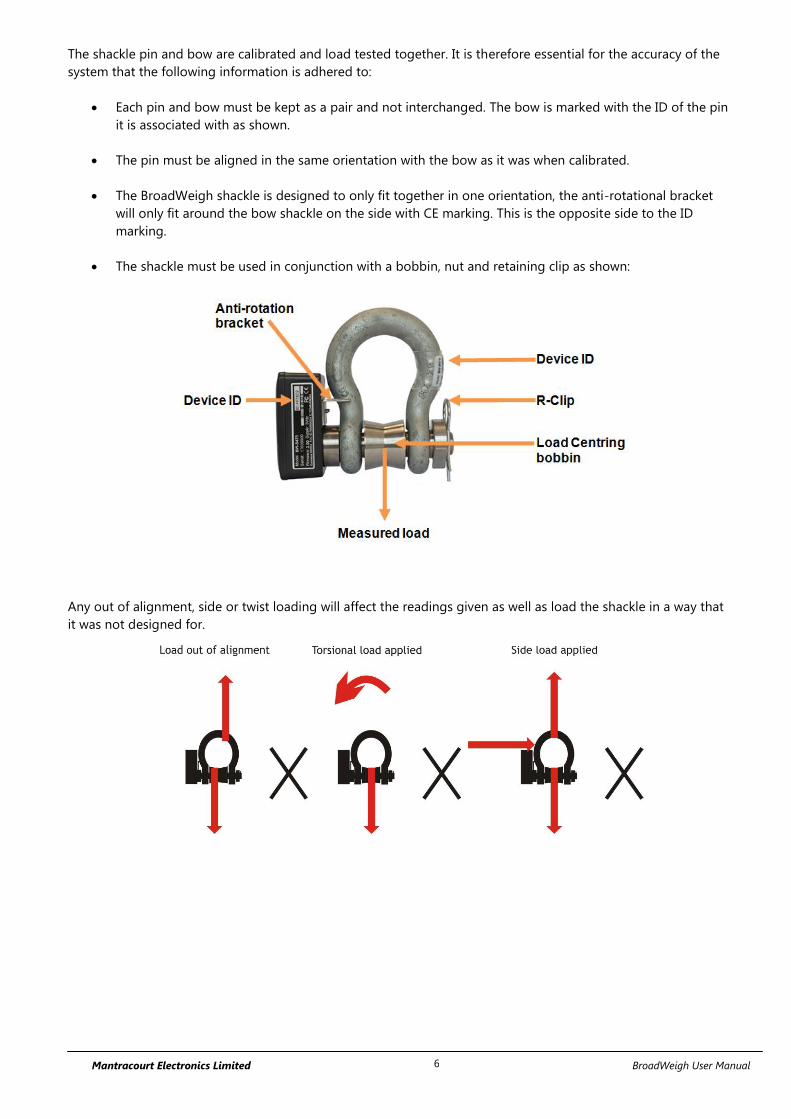
The shackle pin and bow are calibrated and load tested together. It is therefore essential for the accuracy of the
system that the following information is adhered to:
Each pin and bow must be kept as a pair and not interchanged. The bow is marked with the ID of the pin
it is associated with as shown.
The pin must be aligned in the same orientation with the bow as it was when calibrated.
The BroadWeigh shackle is designed to only fit together in one orientation, the anti-rotational bracket
will only fit around the bow shackle on the side with CE marking. This is the opposite side to the ID
marking.
The shackle must be used in conjunction with a bobbin, nut and retaining clip as shown:
Any out of alignment, side or twist loading will affect the readings given as well as load the shackle in a way that
it was not designed for.

Mantracourt Electronics Limited BroadWeigh User Manual 7
If using the shackle as part of a bridle, remember that the load in legs of the bridle will increase with the angle. If
the BroadWeigh shackle pin is not connected to that part of the leg then it will not register this increase.
No part of the shackle or pin should be modified by welding, grinding or similar.
Always ensure that the load is stable.
The allowable operating temperature range is -20°C to +50°C.

Mantracourt Electronics Limited BroadWeigh User Manual 8
The working load limit (WLL) of BroadWeigh shackles assumes the absence of exceptionally hazardous conditions.
These include offshore activities, lifting of persons and lifting of potentially dangerous loads such as molten
metals. In such cases the degree of hazard should be assessed by a competent person and the safe working load
(SWL) reduced accordingly from the working load limit.
Please remember that BroadWeigh does not give advice as to how the data from BroadWeigh shackles is used.
All lifting operations are different and must be supervised by suitably qualified and experienced riggers. It is the
user’s responsibility to ensure conformity with local regulations.
BroadWeigh is not designed to be used as part of a safety critical control system. If it is required for one then the
integrator would need to fully assess its suitability.
BroadWeigh shackle assemblies are subjected to a 150 % proof load (static test coefficient of 1.5) before being
calibrated.

Mantracourt Electronics Limited BroadWeigh User Manual 9
Inspection and Maintenance As with all rigging equipment, BroadWeigh shackles should be inspected before and after every use, ensuring
that all the components are present and correct (bow, pin, bobbin, nut and r clip) and the serial numbers match.
All load bearing components must be free from cuts, nicks, cracks, gouges or excessive wear and distortion. Any
damaged BroadWeigh shackles must be taken out of service and returned to your dealer to arrange
refurbishment or scrapping. If you attempt to replace or swap any load bearing parts yourself the unit’s
calibration will be void.
It is also important before every use to check that all the settings are as expected. The most safety critical settings
to check are that the system zero and the units are correctly set (see the relevant sections in the manual). If these
have been unknowingly changed you could end up with unexpected and misleading readings.
Before moving offset or checking any readings please ensure that the shackle’s temperature has stabilised. When
moved from different temperatures it can take up to an hour to reach the local ambient temperature. Once it has
done so, the readings can accurately be checked.
Always remember that damage to the shackle or its calibration can happen at any time. If you need to move the
zero offset significantly then further investigation is required. This could take the form of a thorough examination
and calibration check with a known load. Records should be kept of any calibration check so that you can see any
movement over time. If the readings are out by more than 1 % or 25 kg or you have to zero out more than 50 kg,
please return to your dealer to arrange recalibration.
These measures should be used in conjunction with your own thorough examination routine at the same intervals
you have set for normal shackles. This will vary due to local regulations but should not be less than every 6
months. Records of all thorough examinations should be kept.
We would recommend checking your shackle’s output with a known load at least once a year and a return to the
factory for a calibration check every two years.
There are very few maintenance requirements. The BroadWeigh shackles and battery enclosures need to be kept
clean, threads clear of debris and protected from corrosion.
Do not overtighten screws when replacing batteries. Damage caused by overtightening is not covered under
manufacturer warranty.
Remove the batteries if being stored for an extended period. Leaking batteries can damage the circuitry.

Mantracourt Electronics Limited BroadWeigh User Manual 10
Product Quick Locator This section allows you to locate your product quickly to navigate to the correct section of the manual.
Shackles
BW-S325 BW-S475
Base Station
BW-BSue
Handheld Display
BW-HR
Relay Output
BW-RM1
Active Repeater
BW-AR
Wind Speed Sensor
BW-WSS
Power Supplies
SP1 PP1
Mantracourt Electronics Limited BroadWeigh User Manual 11
BroadWeigh Basic Principles There are some basic radio settings and concepts that should be understood to effectively configure, deploy,
optimise and troubleshoot BroadWeigh telemetry systems.
Transmitters & Receivers Although all of the BroadWeigh modules are in fact transceivers and transmit as well as receive, they tend to
mainly operate as either a transmitter or receiver so we will choose to describe them as Transmitters and
Receivers.
The BroadWeigh system was designed so that Transmitters are configured to send out messages at a user
defined rate. Receivers can then use this data to analyse, display or perform other actions depending on their
function.
A PC and base station are only required to configure the modules although they may be part of a data collection
system. Once configured the BroadWeigh modules operate autonomously and only minimal control over the
Transmitter modules is usually required, by Receiver modules, such as sleeping or waking.
Transmitters
These are the sensor modules that measure weight or wind speed etc and send messages containing the value
and status information at regular intervals for use by Receiver modules or for delivering to a PC via a base station.
Because these modules need to be very power efficient to operate on batteries they operate in three distinct
modes. See Transmitter Module Modes of Operation later.
Receivers
These modules use messages provided by Transmitters and have functionality such as handheld displays or relay
modules. These modules may also offer control over Transmitter modules such as sleeping or waking.
Radio Channel and Group Key To be able to communicate, two radio modules must share some basic settings. There are ways to learn these and
to recover unknown settings and these are discussed later in the pairing section.
Radio Channel
This is the frequency that the radio operates on. BroadWeigh radio bandwidth is divided into 15 channels.
Modules must be on the same channel to be able to transfer messages.
Group Key
Group keys are a way of isolating groups of modules even if they are operating on the same radio channel. This
can improve efficiency and also offer security because no radio module can affect another or see their messages
unless they share the same group key.
A group key is defined by the user and is up to 15 alphanumeric characters.
Group keys were introduced in v3.0 radio firmware in June 2015. New radio modules will work with older radio
modules but group keys cannot be used.

Mantracourt Electronics Limited BroadWeigh User Manual 12
Configuring Multiple Modules to Use the Same Radio Settings Please note that when you pair to a remote module the base station adopts the radio channel and group key of
the remote module.
To set the group key for a set of remote modules you can either:
Pair to each one in turn and set their radio channel and group key
or
Configure the base station by holding the shift key and clicking the Pair button on the Home page. Then
configure the base station to the required radio settings. Next use the tool on the radio settings
advanced page to pair to each module in the set to configure their radio settings to match the base
station.
ID and Data Tags To configure a module its ID is used in communications. This is a unique 6 character identifier, such as FF1234,
which is allocated at the factory. This ID is hexadecimal so can consist of numbers 0-9 and letters A-F.
If a module is a Transmitter it sends messages without broadcasting its ID. It identifies messages by using a Data
Tag. This tag is a 4 character hexadecimal number and can be configured by the user. When modules leave the
factory this data tag is set to the last 4 characters of its ID.
When Receiver modules or software want to use messages sent by Transmitter modules they identify the
message they want by this Data Tag.
The reason Transmitter module messages are identified by a Data Tag rather than the unique ID is that this allows
replacement of a Transmitter module without having to reconfigure the many Receiver modules that may be
using its messages. It is only necessary to configure the replacement Transmitter module with the same data tag,
radio channel and group key and the rest of the system will not notice the difference.
Transmitter Module Modes of Operation
Normal
Normal mode involves taking a reading and sending a message then entering into a very low power state before
taking the next reading to maximise battery life.
Because it is not possible to communicate with the Transmitter module during this low power state a
‘configuration’ mode is required.
Configuration
Configuration mode forces the modules to pause in sending their messages and to disable their low power state
to enable configuration to take place. This is easily achieved by ‘Pairing’ when using the BroadWeigh Toolkit
software. Once configuration is complete the modules will resume their ‘normal’ mode operation.
Sleep
The last mode is sleep. Modules can be sent to sleep by other modules or they can go to sleep themselves when
their messages are no longer being used. See Sleep Delay Settings later.
When sleeping, the modules can be awakened on demand by other modules or software via the base station.
Transmitter Module Sleep Delay Settings Transmitter modules have a Sleep Delay setting (set in seconds) which allows the modules to go into Sleep mode
when their data messages are no longer required. This allows much longer battery life to be achieved.

Mantracourt Electronics Limited BroadWeigh User Manual 13
Setting Sleep Delay to zero disables this function in the Transmitter modules and they will only go into Sleep
mode when told to do so.
Most Receiver modules and BroadWeigh software send Stay Awake messages when they see messages arrive
from Transmitter modules. In the Transmitter modules, if the Sleep Delay time period has elapsed without a Stay
Awake message arriving then the module will enter Sleep mode.
Usually the Stay Awake messages are sent every 5 seconds so Sleep Delays should be set to at least 10 seconds
but can be set to anything up to an hour for situations where the Receiver is likely to be out of range for periods
of time but where the Transmitter module is required to stay awake and in normal operational mode during that
time. It is usual that Sleep Delays are set somewhere between 30 and 300 seconds when required.
Pairing Because you need to know the radio settings configured in a module to be able to configure it, and there are no
visible clues to what those settings may be, there is a feature used by BroadWeigh modules that enable the radio
settings (i.e. the radio channel and the group key) to be determined and matched between two BroadWeigh
modules.
Pairing is only required to determine and match radio settings and optionally to put BroadWeigh Transmitter
modules in configuration mode. Because in some installations the BroadWeigh modules can be buried deep
inside other equipment there had to be a way of indicating that a module has been selected to pair with without
having physical access to that module. Pairing was therefore designed to be activated by removing and re-
applying the module’s power. In some cases this is not practical so another possible solution is Soft Pairing.
Pairing From BroadWeigh Toolkit
When using the BroadWeigh Toolkit and a base station, pairing is used to connect to a module without having to
know anything about it beforehand. To pair, remove power from the required module, click a ‘Pair’ button in the
software and re-apply power to the module. The base station and module negotiate settings and the base
station is automatically configured to match the radio settings from the module and places the module into
configuration mode. Now the module can be configured and when complete it will return to normal operational
mode.
Pairing From a Receiver Module
Some Receiver modules allow pairing to a Transmitter module without requiring the BroadWeigh Toolkit. For
example, the BW-HR handheld display offers this feature by turning it on while holding a certain key after which
the power is applied to the Transmitter module. The radio settings are then negotiated and the Transmitter
module is automatically configured to match the handheld radio settings. The handheld learns the ID and
data tags required to be able to use messages from the Transmitter module. In this case no configuration mode
is required so the Transmitter module simply continues to operate in normal mode but with altered radio
settings.
Soft Pairing Pairing by power cycling is absolute and will work under all circumstances. However, sometimes access to the
power supply of a module that you want to pair to can be restricted, a module 20 meters up a tower for example,
so the BroadWeigh Toolkit offers a way to soft pair.
To achieve this you need to know the radio channel and group key of the remote module and configure
the base station to match this. You must also know the unique ID of the module and armed with this you
can soft pair to the module. This works well with Receiver modules as they are not operating in low power modes
but the software does need to try and change Transmitter modules from their normal operation mode into
configuration mode therefore modules with transmission intervals greater than 5 seconds may be difficult to soft
pair to.
This may not always work reliably in high traffic or high noise environments because there are a lot of messages
that need to be sent between the base station and the remote module which can be upset by the presence of too
many other messages on the same radio channel.

Mantracourt Electronics Limited BroadWeigh User Manual 14
Configuring an Attached Base Station Because a base station is attached to our computer when you are using the BroadWeigh Toolkit you do not pair
to it the same way as with other BroadWeigh modules. To configure the base station using the Toolkit hold the
shift key and click the Pair button on the Home page.
Asynchronous Operation and Logging Transmitters send their messages at a fixed user defined interval regardless of whether anything is listening. This
message interval is timed from when the Transmitter has been woken or powered on so there is no
synchronisation of when the actual measurement is taken between different transmitters.
If you are logging information from multiple Transmitters using multiple channel logging software you should be
aware of how the software will store and record values.
The software stores the message values as they arrive from each Transmitter and when a log is to be recorded it is
the last value received by each Transmitter that is used.
This means that the values that are recorded could have been measured at any point during the Transmitter
message interval.
For example, if there are 10 Transmitters operating at 1000 ms message interval then when the values are
recorded to the log file you can only be sure that those values had been recorded within 1000 ms of each other.
So if there is a requirement that recorded sets of readings are within a certain time of each other, then that time is
the maximum message interval that should be set for the Transmitters regardless of the actual log interval of the
software (Which should always be greater than the Transmitter message interval).
Bandwidth Each radio channel (1-15) has a finite ability to carry information. When modules do not need to communicate
with each other they can be configured on separate radio channels and do not affect each other.
However, when multiple modules are on the same radio channel, even if they use different group keys, they are
all contributing to filling the available bandwidth.
Each message transmitted takes up around 3 milliseconds so if everything worked perfectly and all modules
transmitted at just the right time and with no gaps between then there could only ever be 300 messages per
second being transmitted on any one radio channel.
In reality there are factors that reduce this capacity.
Each module uses a technique to detect whether anyone else is transmitting before it transmits itself and this
takes a finite time. There can also be interference from other sources that can delay module transmissions.
Because of the transmission rate flexibility of the BroadWeigh modules there could be a few modules transmitting
messages at fast rates or many modules transmitting messages at slow rates or any combination of these.
Practically there is a limit of around 200 messages per second available per radio channel.
It should be noted that as the number of Transmitter modules increases there is more chance of message
collisions and so more messages are lost (remember that the Transmitter modules are sending their messages
out at regular intervals) thus reducing the average number of messages per second arriving per module.
So, for example, 2 modules may transmit at 100 times per second or 100 modules at a rate of 1 per second.
Repeaters and Repeater Subgroups Repeaters are able to retransmit messages so that the repeated signal is stronger than the original and so can
increase the range of systems or can bypass obstacles.
The repeater must be configured to operate on the same radio channel and use the same group keys as those
modules it is repeating.
Because the radio traffic is effectively doubled by a repeater there is a mechanism to reduce unnecessary
repetition of messages.

Mantracourt Electronics Limited BroadWeigh User Manual 15
Sometimes a repeater will still see messages from modules that do not need to be repeated (Thus filling up
available bandwidth) so both repeaters and all other BroadWeigh modules have a setting called the repeater
subgroup.
By default all subgroup settings are set to zero. A repeater will repeat a message from all modules whose
subgroup is either zero or matches its own subgroup. If a repeater subgroup is zero it will repeat messages from
all modules.
This is a simple way to break down modules into smaller groups and control what messages get repeated.
Changing the repeater subgroup is not normally necessary unless the bandwidth is very full due to either many
Transmitter modules being present or very fast transmissions from modules.
Mantracourt Electronics Limited BroadWeigh User Manual 16
BroadWeigh Toolkit To configure the modules you must use the BroadWeigh Toolkit software application. This can be downloaded
from our web site or may be shipped with your products.
The software is suitable for all versions of Windows.
Run setup.exe and follow the prompts to install the software.
In the Toolkit all items that can be changed or interacted with by the user are coloured orange.
To change a value just click on the relevant orange item. You will then be presented with a new dialog window
allowing you to change the value.
This may use a slider, text box or list to allow your new value to be entered.
A base station will also be required to configure the BroadWeigh modules. You just need to plug this into a USB
socket on your PC.
Common Toolkit Pages These pages in the BroadWeigh Toolkit are applicable to all connected modules.
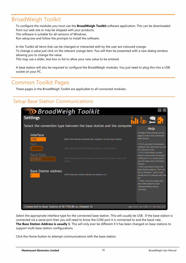
Setup Base Station Communications
Select the appropriate interface type for the connected base station. This will usually be USB. If the base station is
connected via a serial port then you will need to know the COM port it is connected to and the baud rate.
The Base Station Address is usually 1. This will only ever be different if it has been changed on base stations to
support multi base station configurations.
Click the Home button to attempt communications with the base station.

Mantracourt Electronics Limited BroadWeigh User Manual 17
If no communications can be established the toolkit will remain on this page. You will need to check that the base
station is powered and that it is connected to any converters correctly.
Analyser
The analyser page is provided as a tool and will not normally be needed unless you plan to change channels and
want to find the best channel to select, or to diagnose poor communications issues.
This page shows the radio signal levels detected across all the channels available to the BroadWeigh series of
modules. Using this tool may help in detecting noisy areas and allow you to decide on which channels you may
want to use.
The above charts show the traffic from a Wi-Fi network that can be seen to be operating over channels 12 to 16
and it would be best (though not essential) to avoid using these channels.
Although 16 channels are shown the BroadWeigh modules operate over radio channels 1 to 15.

Mantracourt Electronics Limited BroadWeigh User Manual 18
Channel Monitor
This page shows a summary of data sent by transmitter modules.
You can see the Data Tag of transmitted messages along with the total number of messages received, the
transmission rate, link quality, data value and any error messages.
Base stations built after June 2015 can also list modules that are sleeping. These will show an ID instead of a Data
Tag.
To see any data the base station must be on the same radio channel as the transmitters
and must have a matching Group Key
The radio channel of the base station can be changed by clicking the channel tabs along the top of the page.
If you want to change the Group Key of the attached base station you need to configure its radio settings. See
Configure Base Station
Items you can change or interact with:
Radio Channel Tabs Click a tab to change the radio channel the base station is operating on
Clear List Clear all detected messages from the list
Wake All Wake all modules on the current radio channel
Mantracourt Electronics Limited BroadWeigh User Manual 19
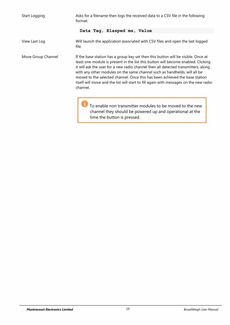
Start Logging Asks for a filename then logs the received data to a CSV file in the following
format:
Data Tag, Elasped ms, Value
View Last Log Will launch the application associated with CSV files and open the last logged
file.
Move Group Channel If the base station has a group key set then this button will be visible. Once at
least one module is present in the list this button will become enabled. Clicking
it will ask the user for a new radio channel then all detected transmitters, along
with any other modules on the same channel such as handhelds, will all be
moved to the selected channel. Once this has been achieved the base station
itself will move and the list will start to fill again with messages on the new radio
channel.
To enable non transmitter modules to be moved to the new
channel they should be powered up and operational at the
time the button is pressed.

Mantracourt Electronics Limited BroadWeigh User Manual 20
Home
You now have successful communications with the base station so you can now pair with our remote BroadWeigh
module or you can select the Spectrum Analyser mode or Data Provider Monitor mode.
Connecting to a remote module
To connect to a remote module you will pair. This is achieved by power cycling the module. Pairing removes the
need to know the radio settings of the module you are connecting to and also ensures that it is in a suitable state
for configuration.
Pairing Procedure
Remove power from the BroadWeigh module.
Click the Pair button on the Toolkit.
Re-apply power to the BroadWeigh module within 10 seconds.
When you connect successfully the Toolkit will change to the Information page. If the pairing fails try again.
Pairing with the toolkit will not change the radio configuration settings of the connected
module. The base station radio settings will be changed to match those of the remote
module.
When the toolkit connects to a remote module to enable configuration it will usually
inhibit the normal operational transmission of messages

Mantracourt Electronics Limited BroadWeigh User Manual 21
Connecting to the attached base station module
To pair to and configure the connected base station, hold the shift key and click the Pair button.
Manual Connection
If you cannot get to the power supply of the remote module you can attempt to connect manually using Soft
Pairing. Click the ‘Click Here’ link at the bottom of the page and follow the prompts.

Mantracourt Electronics Limited BroadWeigh User Manual 22
Information
Once successfully paired to a module this page is displayed showing us information about the connected module.
Items you can change:
Name You can enter a short description which may help us recognise this module in the
future.
Features
Each module may support certain features which are indicated on this page. If the feature is greyed out then it is
not supported. If it is coloured then it is supported.
Some transmitter modules may have had their calibration protected. This
indicates that you cannot calibrate this module.
Group Keys were introduced in 2015 so modules built before this date will not
support this feature. This indicates that the connected module can support them
This indicates that the connected module can support Group Keys and that one
has been configured for this module
Applicable to a base station only. This indicates that on the Channel Monitor page
modules that are sleeping will also be listed
Extended range radios were introduced to the BroadWeigh range in 2015. This
indicates that the connected module has an extended range radio fitted.

Mantracourt Electronics Limited BroadWeigh User Manual 23
Battery and Radio Levels
Here you can see the voltage of the battery and the radio signal levels at the base station and the remote
transmitter module. This simple view gives an LQI value which stands for Link Quality Indicator. This value will
range from 0 to 100 and anywhere within this band you should still achieve communications. As the level drops
towards zero communications may become intermittent but still achievable.
On modules that are battery powered the battery voltage section will be visible. You can set the level at which the
transmitter module reports a low battery. (At 2.1 V the module will stop working)
If the battery voltage is below the Low Battery Level the bar will be coloured orange.
Items you can change:
Low Battery Level Click this item to set the battery low level.
Advanced Button Clicking this will give more detailed information on the RSSI and CV levels of the
received radio packets.

Mantracourt Electronics Limited BroadWeigh User Manual 24
Battery and Radio Levels Advanced
LQI value which stands for Link Quality Indicator. This value will range from 0 to 100 and within this band you
should still achieve communications. As the level drops towards zero communications may become intermittent
but still achievable. The LQI value is derived from the RSSI and CV values.
RSSI is the Radio Signal Strength Indicator and indicates the received dB level which will range from about -30
which is a good signal to -98 which is a weak signal.
CV is the Correlation Value and indicates how well the signal can be decoded. This ranges from 55 which is a poor
quality signal and 110 which is an excellent signal.

Mantracourt Electronics Limited BroadWeigh User Manual 25
Radio Settings
Here you can change the channel and group key for the connected module.
Items you can change:
Channel Select a radio channel between 1 and 15. The default is channel 1. You can use the
Spectrum Analyser mode to determine a good clean channel to use.
Group Key Only visible on modules that support Group Keys.
Only modules with identical group keys can communicate. This allows isolation of
different groups of modules on the same channel or ensures the security of data.
Early versions of BroadWeigh modules do not support Group Keys and this option
will not be visible in the Toolkit.
To use modules that support Group Keys with older modules that do not then
the Group Keys must be blank.
The following two options are not visible when changing radio settings for a base
station. In that case changes are immediate.
Reset Module Only Only enabled once a change has been made.
When radio settings are changed they do not take effect immediately but require a
reset or power cycle. This button forces the connected module to adopt the new
settings but keeps the base station on the existing settings. The home page is then
shown.
Reset Module and base
Station
Only enabled once a change has been made.
When radio settings are changed they do not take effect immediately but require a
reset or power cycle. This button forces both the connected module and the base
station to adopt the new changes and re-establishes a connection.

Mantracourt Electronics Limited BroadWeigh User Manual 26
Radio Settings Advanced
Here you can change the repeater subgroup settings for the connected module. Also a tool is provided to quickly
match remote module radio settings to the base station radio settings.
Items you can change:
Repeater Subgroup Select a repeater subgroup for this module. The default is zero which will let all
repeaters repeat messages from this module. See Repeaters and repeater
Subgroups
Remote Module Radio
Settings Tool
To quickly set a batch of remote modules to match the radio settings of the base
station you can use this tool. Usually this is arrived at by pairing with the base
station by holding the shift key whilst clicking the Pair button on the Home page.
To change the remote module radio settings:
Remove remote module power
Click the ‘Click Here’ link on the page
Apply power to the remote module
The Toolkit will remain unchanged and still paired to whatever module or base
station it was paired to but the remote module will have changed its radio
settings.
Mantracourt Electronics Limited BroadWeigh User Manual 27
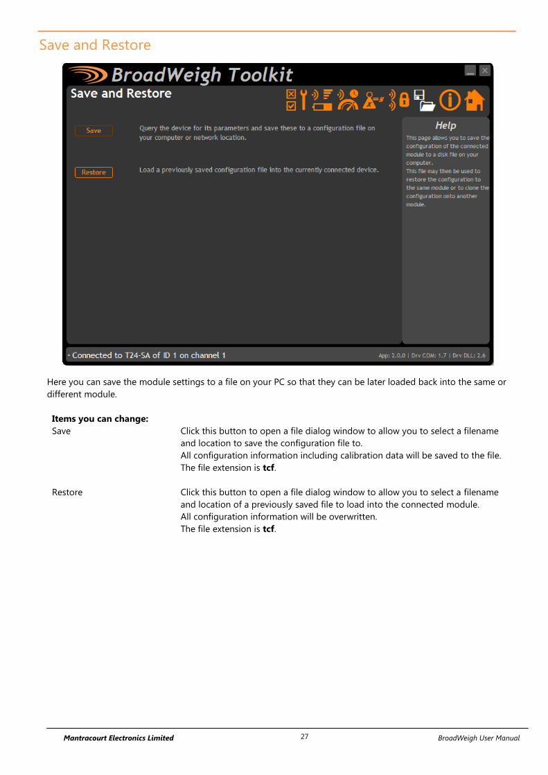
Save and Restore
Here you can save the module settings to a file on your PC so that they can be later loaded back into the same or
different module.
Items you can change:
Save Click this button to open a file dialog window to allow you to select a filename
and location to save the configuration file to.
All configuration information including calibration data will be saved to the file.
The file extension is tcf.
Restore Click this button to open a file dialog window to allow you to select a filename
and location of a previously saved file to load into the connected module.
All configuration information will be overwritten.
The file extension is tcf.

Mantracourt Electronics Limited BroadWeigh User Manual 28
Transmitter Modules BroadWeigh Transmitters are the modules that connect to a sensor or have an input signal applied and
periodically transmit messages containing the value read from the sensor or input. These modules include shackle
load cell transmitters and wind speed sensor transmitters.
BW-S325, BW-S475
Overview
The BroadWeigh Shackle is a Crosby safety bow shackle with integrated electronics which features the following:
Available in 4 ¾ tonne or 3 ¼ tonne options
Up to 800 m line of sight wireless transmission range
Fully weatherised (IP67)
5:1 safety factor
Low rigging profile of 130 mm
2000 hr battery life at transmission 1 per second
Sleep function to preserve battery life when not needed
Accuracy of ±1% of current load or 25 kg, whichever is the greater value
Order Codes
BW-S325
Load shackle with SWL of 3.25 tonnes.
BW-S475
Shackle capable of measuring up to 4.75 tonnes.
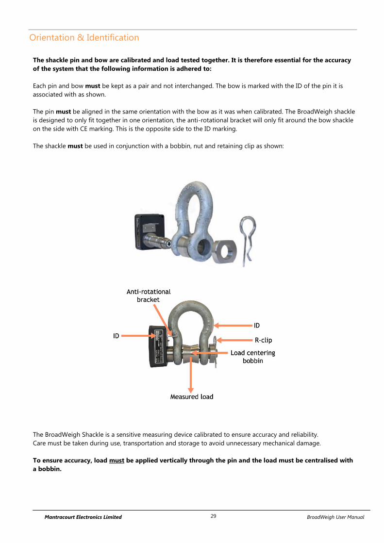
Mantracourt Electronics Limited BroadWeigh User Manual 29
Orientation & Identification
The shackle pin and bow are calibrated and load tested together. It is therefore essential for the accuracy
of the system that the following information is adhered to:
Each pin and bow must be kept as a pair and not interchanged. The bow is marked with the ID of the pin it is
associated with as shown.
The pin must be aligned in the same orientation with the bow as it was when calibrated. The BroadWeigh shackle
is designed to only fit together in one orientation, the anti-rotational bracket will only fit around the bow shackle
on the side with CE marking. This is the opposite side to the ID marking.
The shackle must be used in conjunction with a bobbin, nut and retaining clip as shown:
The BroadWeigh Shackle is a sensitive measuring device calibrated to ensure accuracy and reliability.
Care must be taken during use, transportation and storage to avoid unnecessary mechanical damage.
To ensure accuracy, load must be applied vertically through the pin and the load must be centralised with
a bobbin.
LOAD

Mantracourt Electronics Limited BroadWeigh User Manual 30
Connections
Connecting Power.
To ensure optimum battery life, only quality alkaline batteries are recommended.
Rechargeable batteries are not suitable.
Remove the four screws. Insert two alkaline 1.5 V AA batteries. Refit the lid.

Mantracourt Electronics Limited BroadWeigh User Manual 31
Configuration
The BroadWeigh Toolkit provides a means of simple configuration and calibration of the shackle along with
useful tools to aid integration.
Launch the BroadWeigh Toolkit software application and pair to this module to enable the connection to the
Toolkit to allow configuration to take place. See Common Toolkit Pages - Home
Units
Use this page to select the Output units of the Paired BroadWeigh Shackle.
Parameters:
Output Units Use the drop down box to select between kg, lbs, tonnes, ton, ton (US) & kN.
If these units are changed ensure the Zero Indication Band is also set correctly.

Mantracourt Electronics Limited BroadWeigh User Manual 32
Zero Settings
Use this page to perform system zero and to hide small values of weight (masking) for the paired BroadWeigh
Shackle
Parameters:
Zero Indication Band This setting enables you to hide small values of weight so that any displays
based on the output from this module will display zero until a certain weight
has been reached. You can enter a value here that represents a ± band around
zero so that if the value to be transmitted is within this band a zero will be
transmitted. Once the weight exceeds this band the full weight will be
transmitted.
For example: A BroadWeigh Shackle with a 5.0 kg Zero Indication Band will only
transmit a zero value until 5 kg of weight or more is applied when it will then
transmit the applied weight value.
If you change the module units you will need to adjust the zero indication
band again.
System Zero If the unloaded shackle is displaying a small weight you can re-zero the output
value by applying a system zero.
Remove the load from the shackle before clicking the ‘Zero Now’ button.
Output Value This shows the weight value that will be transmitted and shows the effect of the
system zero and the zero indication band.

Mantracourt Electronics Limited BroadWeigh User Manual 33
Data Rates and Quality
Use this page to select the rate at which data is transmitted from the acquisition module and the quality. By
selecting low power mode and entering some other information the toolkit will also give guides on achievable
battery life.
Note that the battery life calculator assumes a 20°C ambient temperature. To ensure optimum battery life, only
quality alkaline batteries are recommended. Rechargeable batteries are not suitable.
Parameters:
Transmit Interval Enter the transmission rate in milliseconds. The default is 1000 ms for
BroadWeigh Shackles.
Longer battery life will be achieved with less frequent transmissions.
Sample Time This is the length of time in milliseconds that the input is sampled before the
value is transmitted. This can vary between 5 ms and close to the Transmit
Interval. A shorter sample time means that the device is awake for less time so
battery life is increased but at the expense of a reading with less noise free
resolution. Alter this to see the effect on battery life and noise free resolution.
Low Power Mode Low power mode is the usual mode of operation and increases battery life. If
the transmission interval were increased above 25 Hz (40 ms transmit interval)
then low power mode would need to be turned off.
Continued…

Mantracourt Electronics Limited BroadWeigh User Manual 34
Battery Type This is not a parameter of the device but information used by the battery life
guide. Choose from some pre-set battery parameters or choose custom and
select chosen battery capacity. See below. This will also offer to change the
Battery Low Level if the level suitable for the chosen battery is not the level
currently set.
Usable Capacity This is not a parameter of the device but information used by the battery life
guide. This is the capacity of the battery in amp hours and has a profound effect
on battery life calculations. This capacity needs to be calculated from battery
manufacturer’s data sheets to take into account that you can only use batteries
down to 2.1 volts so in the case of twin AA cells this would be 1.05 volts.
Generally the usable capacity will not be as high as that advertised by the
battery manufacturer. Temperature and internal resistance of the battery are not
taken into account in the guide.
Sensor Resistance This is fixed at 1000 ohms.
Usage Per 24 Hour Period In order to calculate battery life, enter the number of hours per 24-hour period
that the BroadWeigh Shackle will be connected to a BroadWeigh USB base
station or Handheld remote
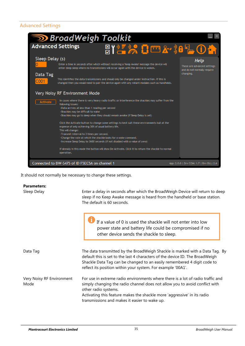
Mantracourt Electronics Limited BroadWeigh User Manual 35
Advanced Settings
It should not normally be necessary to change these settings.
Parameters:
Sleep Delay Enter a delay in seconds after which the BroadWeigh Device will return to deep
sleep if no Keep Awake message is heard from the handheld or base station.
The default is 60 seconds.
If a value of 0 is used the shackle will not enter into low
power state and battery life could be compromised if no
other device sends the shackle to sleep.
Data Tag The data transmitted by the BroadWeigh Shackle is marked with a Data Tag. By
default this is set to the last 4 characters of the device ID. The BroadWeigh
Shackle Data Tag can be changed to an easily remembered 4 digit code to
reflect its position within your system. For example ‘00A1’.
Very Noisy RF Environment
Mode
For use in extreme radio environments where there is a lot of radio traffic and
simply changing the radio channel does not allow you to avoid conflict with
other radio systems.
Activating this feature makes the shackle more ‘aggressive’ in its radio
transmissions and makes it easier to wake up.

Mantracourt Electronics Limited BroadWeigh User Manual 36
Enclosure & Mounting
Dimensions
BW-S325 BroadWeigh Shackle 3.25T dimensions
BW-S475 BroadWeigh Shackle 4.75T dimensions
Mantracourt Electronics Limited BroadWeigh User Manual 37
Opening the Case
Remove the four screws, see Connecting Power
LED Indicator
The Broadway Shackle is fitted with an LED to provide a visual indication of data transmission from the acquisition
module inside. The LED flashes whenever a data transmission occurs. Modules are pre-configured to provide
readings once per second.
Flashing data transmitting
Constant paired to BroadWeigh Toolkit
Off unit asleep

Mantracourt Electronics Limited BroadWeigh User Manual 38
Specification
Measurement Min Typical Max Units
Weight Range (SWL) 3250 or 4750 kg
Accuracy Typically ±1% of load or ±25 kg whichever is greater
Power Supply Min Typical Max Units
Estimated Battery life 2 X AA Duracell
batteries (1 update per second):
Asleep 5+ Years
Continuous operation 3 Months
8 Hours Usage Per Day 8 Months
2 Hours Usage Per Day 2.5 Years
Environmental Min Typical Max Units
IP rating IP67
Operating temperature range -20 +50 °C
Storage temperature* -40 +85 °C
Humidity 0 95 %RH
* Excludes Batteries.
Radio Range
For details of radio range please refer to Appendix B – Radio Range

Mantracourt Electronics Limited BroadWeigh User Manual 39
BW-WSS
Overview
The BW-WSS wireless anemometer is built on the same technology as other BroadWeigh wireless sensor
interfaces offering the same sleep and wake functionality and operation with peripheral modules including
handhelds and USB base stations.
The Anemometer features a high quality 3-cup rotor pressed on a stainless steel shaft with rugged Delrin body
with bronze Rulon bushings
The output value of the anemometer can be configured to the user’s requirements and measure over the range 5
to 125 mph.
Accuracy:
0.5 mph from 5 to 10 mph
± 4% from 10 to 125 mph
The BW-WSS is powered either from internal batteries or an external supply. For applications which require high
sampling rates for long periods BroadWeigh’s PowerPack and SolarPanel (PP1 & SP1) offers an ideal solution.
Order Codes
BW-WSS
Wireless wind speed transmitter module mounted in large weatherproof enclosure with battery holder for
two D cell alkaline batteries. Also has ability to be powered from external supply voltage.

Mantracourt Electronics Limited BroadWeigh User Manual 40
Connections
Power
Power can be supplied by fitting two D cell alkaline 1.5 V batteries or the module can be supplied from an
external 5 Vdc to 18 Vdc source. The module will switch to the external supply in preference providing a battery
backup.
In both cases the JP1 power jumper needs to be fitted to supply power to the transmitter module.
When powered from the external DC source the LED will illuminate.
2 X D Cell Batteries
AB
0V+Supply
12345
Power Jumper JP1
LED
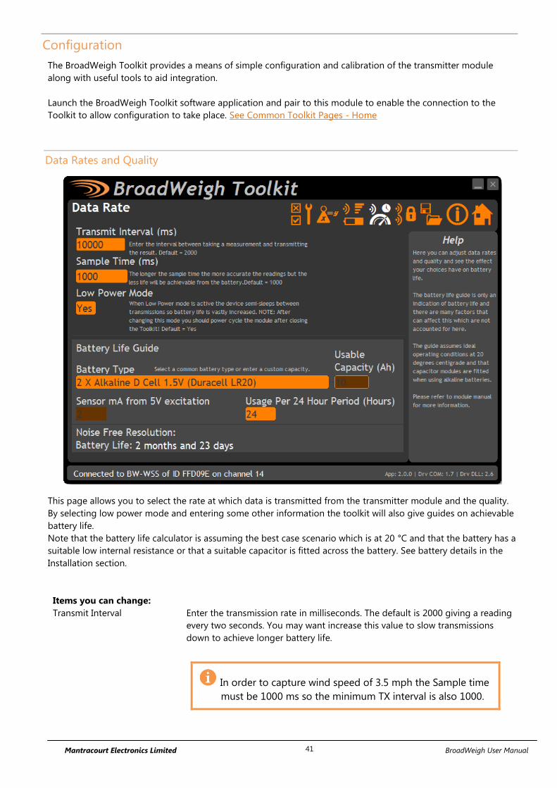
Mantracourt Electronics Limited BroadWeigh User Manual 41
Configuration
The BroadWeigh Toolkit provides a means of simple configuration and calibration of the transmitter module
along with useful tools to aid integration.
Launch the BroadWeigh Toolkit software application and pair to this module to enable the connection to the
Toolkit to allow configuration to take place. See Common Toolkit Pages - Home
Data Rates and Quality
This page allows you to select the rate at which data is transmitted from the transmitter module and the quality.
By selecting low power mode and entering some other information the toolkit will also give guides on achievable
battery life.
Note that the battery life calculator is assuming the best case scenario which is at 20 °C and that the battery has a
suitable low internal resistance or that a suitable capacitor is fitted across the battery. See battery details in the
Installation section.
Items you can change:
Transmit Interval Enter the transmission rate in milliseconds. The default is 2000 giving a reading
every two seconds. You may want increase this value to slow transmissions
down to achieve longer battery life.
In order to capture wind speed of 3.5 mph the Sample time
must be 1000 ms so the minimum TX interval is also 1000.

Mantracourt Electronics Limited BroadWeigh User Manual 42
Sample Time
CHANGING THIS VALUE WILL EFFECT THE INPUT RANGE OF
THE SENSOR
This is the length of time in milliseconds that the input is sampled before the
value is transmitted. The default value is 1000 ms allowing for wind speeds from
3.5 mph upward to be captured.
Low Power Mode This module should be set to Low Power Mode.
Battery Type This is not a parameter of the module but information used by the battery life
guide. You can choose from some preset batteries or choose custom to allow
you to select your own battery capacity. See below. This will also offer to change
the Battery Low Level if the level suitable for the chosen battery is not the level
currently set.
Usable Capacity This is not a parameter of the module but information used by the battery life
guide. This is the capacity of the battery in amp hours and has a profound effect
on battery life calculations. This capacity needs to be calculated from battery
manufacturer’s data sheets to take into account that you can only use batteries
down to 2.1 volts so in the case of twin AA cells this would be 1.05 volts.
Generally the usable capacity will not be as high as that advertised by the
battery manufacturer. Temperature and internal resistance of the battery are not
taken into account in the guide.
Sensor mA from 5 V
Excitation
This is the current drawn by the sensor; this should be set to 2mA for the BW-
WSS to provide a conservative battery life guide.
Usage Per 24 Hour Period Enter the number of hours per 24 hour period that the module will be turned on
and transmitting.
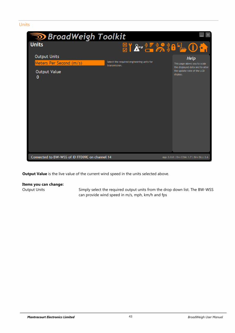
Mantracourt Electronics Limited BroadWeigh User Manual 43
Units
Output Value is the live value of the current wind speed in the units selected above.
Items you can change:
Output Units Simply select the required output units from the drop down list. The BW-WSS
can provide wind speed in m/s, mph, km/h and fps

Mantracourt Electronics Limited BroadWeigh User Manual 44
Advanced Settings
You should not normally need to change these settings.
Items you can change:
Sleep Delay Here you can enter a delay in seconds after which the transmitter module will
return to deep sleep if no Keep Awake message is heard from software,
handheld or other receiving modules. The default is 60 seconds.
Data Tag The data transmitted by the transmitter module is marked with a Data Tag
which is a 2 byte hexadecimal code. By default this is set to the last 2 bytes of
the module ID (or to put it another way, the last 4 characters of the module ID).
If by some chance you had two transmitter modules that would be working on
the same channel and had the same last 4 characters in their ID (1 in 65535
chances) you may want to change the data Tag of one of the modules and
perform pairing again with the handheld.
Transmit power Set the transmit power level from 0–100%. Default is 100%
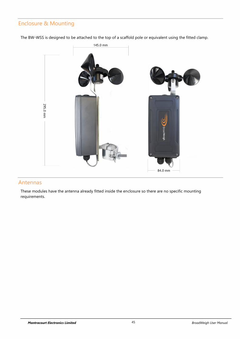
Mantracourt Electronics Limited BroadWeigh User Manual 45
Enclosure & Mounting
The BW-WSS is designed to be attached to the top of a scaffold pole or equivalent using the fitted clamp.
Antennas
These modules have the antenna already fitted inside the enclosure so there are no specific mounting
requirements.

Mantracourt Electronics Limited BroadWeigh User Manual 46
Specification
Specification at 3V supply at 25°C
Parameter Min Typical Max Units
Battery Supply Voltage 2.1 3 3.6 Vdc
External DC Supply 5 18 Vdc
Operating Temperature Range -20 - 55 °C
Storage Temperature Range -40 - 85 °C
Humidity 95 %RH
Reverse Polarity Protection - -32 Vdc
Environmental protection with suitable cables
exiting through cable glands.
IP67
Measurement Range 5 - 125 mph
Accuracy 5 – 10 mph 0.5 mph
Accuracy 10 – 125 mph ±4% mph
Environmental Min Typical Max Units
Operating temperature range -40 +85 °C
Storage temperature -40 +85 °C
Humidity 0 95 %RH
Power Supply Min Typical Max Units
Standby / Low power mode 5 20 µA
Normal Mode on constantly 55 60 mA
Power Supply voltage 5 18 Vdc
Power Supply ripple 50 mV ac pk-pk
Battery Life in Low Power Mode
Generating Results every 2 seconds
With sample time of 1 second
Usage Battery Life
Pair D cells Constantly on 14 days
Pair D cells 12 sessions per day of 5 minutes 1 year
Radio Range
For details of radio range please refer to Appendix B – Radio Range

Mantracourt Electronics Limited BroadWeigh User Manual 47
Receiver Modules
Receiver modules use the messages sent by the transmitter modules. These modules may process or display this
information or convert the data into a different physical format.
BW-HR
Overview
The BW-HR is a roaming handheld that can be used to view the reading supplied by an unlimited number of
BroadWeigh shackles. The shackle module Data Tags or IDs do not need to be known beforehand.
The handheld will automatically wake any shackle on the same channel and group key.
An internal list is maintained of the top n number of transmitter modules ordered by signal level and a Next key
on the handheld allows cycling through this list.
The list size (n) is variable between 2 and 20 and this enables the viewing experience to be tailored to particular
applications.
The transmitter modules are identified by their 4 character hexadecimal Data Tags and these may be set using the
BroadWeigh Toolkit.
When in communication with a particular shackle the LED on that shackle is activated. This provides visual
feedback of the selected and currently viewed shackle.
Order Codes
BW-HR
Handheld display for unlimited number of shackles in a robust weatherproof enclosure.

Mantracourt Electronics Limited BroadWeigh User Manual 48
Connections
Power
The handheld module is powered by two alkaline AA batteries.
Due to the higher voltage requirements of this module NiMh and NiCad batteries are not
recommended.

Mantracourt Electronics Limited BroadWeigh User Manual 49
Operation
View readings
Turn the handheld on by pressing and holding the symbol (on the right) until the display is active. This will
wake the radio and measurement system in the BroadWeigh shackle(s). The factory default displayed value is in
kg.
The handheld display automatically switches ‘on’ the shackles as soon as they are in range. The handheld will then
display the shackle with the strongest signal – in most cases the nearest shackle.
Select a new shackle to display by pressing the key and the shackle data tag will be shown briefly before the
reading is displayed. The data tag is (by default) the last 4 characters of the ID which can be found on the shackle
label.
By pressing and holding the key, the shackle Data Tag currently being measured will be shown.
The currently selected shackle LED will also change from flashing to permanently on.
The handheld can read from an unlimited number of shackles.
The BroadWeigh shackles is pre-set to return to sleep 60 seconds after the handheld is turned off or is taken
out of range.
TIP! – The BroadWeigh Shackle Data Tag can be changed to an easily remembered 4 digit
hexadecimal code to reflect its position within your system. For example ‘A001’. See
BroadWeigh Shackle – Advanced settings.
Keys
Power Key - Press and hold the power key for approximately 2 seconds then
release the key.
This will toggle between turning the handheld on and off.
Can also be used, by giving a quick press, to reset the Auto-Sleep delay.
Next Key - Selects the next shackle to view.
Pressing and holding will display the currently viewed module Data Tag without
moving to the next module.
Indicators
SIG LOW The radio signal from the shackle is low. The shackle is still functioning but the
limit of the range may be near. Communications may start to deteriorate when
this indicator is visible. Until ------ is displayed the communications is still OK and
the display can be relied on for accuracy.
Even with a degraded signal the display value will always be
correct.
BATT LOW The batteries in the handheld are low and need to be replaced.

Mantracourt Electronics Limited BroadWeigh User Manual 50
REMOTE ERROR The shackle has an error that the handheld does not recognise.
REMOTE BATT LOW The battery in the shackle is low.
Errors
Displayed on handheld LCD.
Error 1 The shackle is in shunt calibration mode. An external module or software may
have placed the shackle in Shunt Calibration mode so rather than display a
misleading reading this error is displayed instead.
Error 2 Input integrity error. The shackle module has found a problem with the input.
There may be open or short circuits. Rather than display a misleading reading this
error is displayed instead.
Overload The overload limit set by the user has been exceeded.
Special Modes
Pair
The handheld has the ability to configure a shackle to match the handheld’s own
radio channel and group key settings.
Ensure that the transmitter module is unpowered for at least 10 seconds.
Locate the upper left key by feeling for a slight bump on the label.
Press and hold this key for 5 seconds until PAIRING appears on the LCD.
Release the key and apply power to the shackle.
The amount of time you have to reapply power to the transmitter module can be
set by PairDuration in the BroadWeigh Toolkit when connected to the BW-HR.
This defaults to 5 seconds.

Mantracourt Electronics Limited BroadWeigh User Manual 51
System Zero
The handheld has the ability to perform a system zero on a shackle. This may be
useful after installing new shackles and enables system zero to be set without the
need for a PC/laptop and BroadWeigh Toolkit.
Set the handheld to view the desired shackle by using the Next key.
Locate the upper right key and lower right key by feeling for slight bumps on the
label.
Press and hold these keys for around 8 seconds until ZERO appears on the LCD.
Release the keys and the display should then show the zeroed reading.
This system zero is performed at the shackle and is stored through power cycling.
You cannot remove a system zero using this function. You
can only re-zero.
To remove a system zero you must pair to the shackle using
the Toolkit and remove it from there.
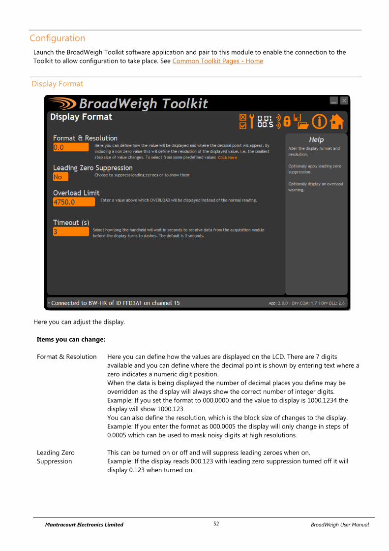
Mantracourt Electronics Limited BroadWeigh User Manual 52
Configuration
Launch the BroadWeigh Toolkit software application and pair to this module to enable the connection to the
Toolkit to allow configuration to take place. See Common Toolkit Pages - Home
Display Format
Here you can adjust the display.
Items you can change:
Format & Resolution Here you can define how the values are displayed on the LCD. There are 7 digits
available and you can define where the decimal point is shown by entering text where a
zero indicates a numeric digit position.
When the data is being displayed the number of decimal places you define may be
overridden as the display will always show the correct number of integer digits.
Example: If you set the format to 000.0000 and the value to display is 1000.1234 the
display will show 1000.123
You can also define the resolution, which is the block size of changes to the display.
Example: If you enter the format as 000.0005 the display will only change in steps of
0.0005 which can be used to mask noisy digits at high resolutions.
Leading Zero
Suppression
This can be turned on or off and will suppress leading zeroes when on.
Example: If the display reads 000.123 with leading zero suppression turned off it will
display 0.123 when turned on.

Mantracourt Electronics Limited BroadWeigh User Manual 53
Overload Limit You can enter a limit here above which Overload will be shown on the display instead
of the actual value.
Enter zero to disable this feature.
Timeout Enter the timeout in seconds. This sets the time allowed without any data arriving from
the viewed module before all dashes are displayed on the LCD. Should be at least 3
times the interval between the messages being sent by the transmitter module.
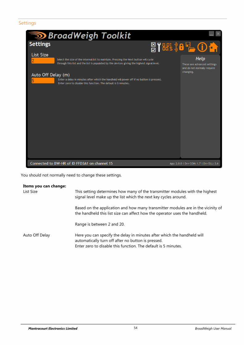
Mantracourt Electronics Limited BroadWeigh User Manual 54
Settings
You should not normally need to change these settings.
Items you can change:
List Size This setting determines how many of the transmitter modules with the highest
signal level make up the list which the next key cycles around.
Based on the application and how many transmitter modules are in the vicinity of
the handheld this list size can affect how the operator uses the handheld.
Range is between 2 and 20.
Auto Off Delay Here you can specify the delay in minutes after which the handheld will
automatically turn off after no button is pressed.
Enter zero to disable this function. The default is 5 minutes.

Mantracourt Electronics Limited BroadWeigh User Manual 55
Enclosure & Mounting
See Appendix A – Handheld Style section for more information.
Antennas
These modules have the antenna already fitted inside the enclosure so there are no specific mounting
requirements.

Mantracourt Electronics Limited BroadWeigh User Manual 56
Specification
Electrical Min Typical Max Units
Power Supply voltage 2.5 3.0 3.6 Vdc
Power Supply Min Typical Max Units
Active 35 40 mA
Low power mode 120 160 µA
Estimated Battery life using 2Ahr batteries:
Standby mode (Powered off) 1.5 Years
Continuous operation 40 Hours
Environmental Min Typical Max Units
IP rating IP67
Operating temperature range -10 +50 °C
Storage temperature -40 +85 °C
Humidity 0 95 %RH
Physical
Hand Held Dimensions 90 x 152 x 34 mm
Radio Range
For details of radio range please refer to Appendix B – Radio Range

Mantracourt Electronics Limited BroadWeigh User Manual 57
BW-RM1
Overview
The BW-RM1 offers dual power relays capable of mains power switching. These relays can be configured as high,
low or window alarms and can be associated with a group of up to 8 BroadWeigh transmitter modules per relay.
Relays can operate when the sum of the assigned transmitter modules reach a set point or when any of the
modules reach the set point. There is also a mode where the difference between the lowest and highest value is
compared to the set point. This is useful for applications where you are looking for a group of weights to be
within a certain band. i.e. hanging truss.
Relays can be latched and a digital input or external command can be used to reset them.
An alarm/error signal relay is operated if communication is lost or other selectable errors occur and this alarm
resets once the source of the alarm or error is removed.
This module is supplied in an IP67 sealed ABS case.
The state of the power relays during an error can be selected.
Order Codes
BW-RM1
Relay module housed in weatherproof enclosure.

Mantracourt Electronics Limited BroadWeigh User Manual 58
Connections
Power
You will need to connect power to the BW-RM1 for it to operate. Only power is required to enable configuration
using a base station and the appropriate toolkit software.
Power is connected to the two part two way screw terminal connector as shown in the diagram below.
Connections & Indicators
LEDs
Mode Flashes 2 x per second when operational
Activity Flashes when BroadWeigh data packets are received
Time Out No BroadWeigh data present for longer than user defined period
Error One or more contributing modules are reporting an error
Relay 1 Relay 1 Energised (Connection between COM and NO)
Relay 2 Relay 2 Energised (Connection between COM and NO)
Inputs
Digital Input 1 Can either reset a latched relay 1 or transmit a Data Provider Packet of a specified Data Tag
Digital Input 2 Can either reset a latched relay 2 or transmit a Data Provider Packet of a specified Data Tag
Digital Input 3 Resets both latched relays
RELAY 2
CO
M
NO
NC
GN
D
Inp
ut
1
GN
D
Inp
ut
2
NC
1
CO
M
1
NO
1
NC
2
CO
M
2
NO
2
+v
0V
RELAY 1
9 – 32 V Supply
+v
0V
ALARM RELAY
DIGITAL INPUTS
Inp
ut 3
GN
D
DIGITAL INPUT
Mode
Activity
Time Out
Error
Relay 1
Relay 2
Pair
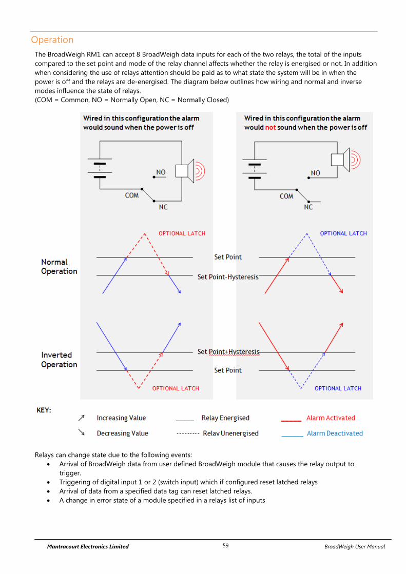
Mantracourt Electronics Limited BroadWeigh User Manual 59
Operation
The BroadWeigh RM1 can accept 8 BroadWeigh data inputs for each of the two relays, the total of the inputs
compared to the set point and mode of the relay channel affects whether the relay is energised or not. In addition
when considering the use of relays attention should be paid as to what state the system will be in when the
power is off and the relays are de-energised. The diagram below outlines how wiring and normal and inverse
modes influence the state of relays.
(COM = Common, NO = Normally Open, NC = Normally Closed)
Relays can change state due to the following events:
Arrival of BroadWeigh data from user defined BroadWeigh module that causes the relay output to
trigger.
Triggering of digital input 1 or 2 (switch input) which if configured reset latched relays
Arrival of data from a specified data tag can reset latched relays.
A change in error state of a module specified in a relays list of inputs

Mantracourt Electronics Limited BroadWeigh User Manual 60
The BW-RM1 also features a third Alarm relay. The Alarm relay is energised from start up, (alarm connection
made between COM and NC). The relay de-energises if an error is detected. An error is classed as a timeout and
optionally can include Integrity error or low Battery. The Alarm Relay will return to normal (energised) once the
source of the error is removed.
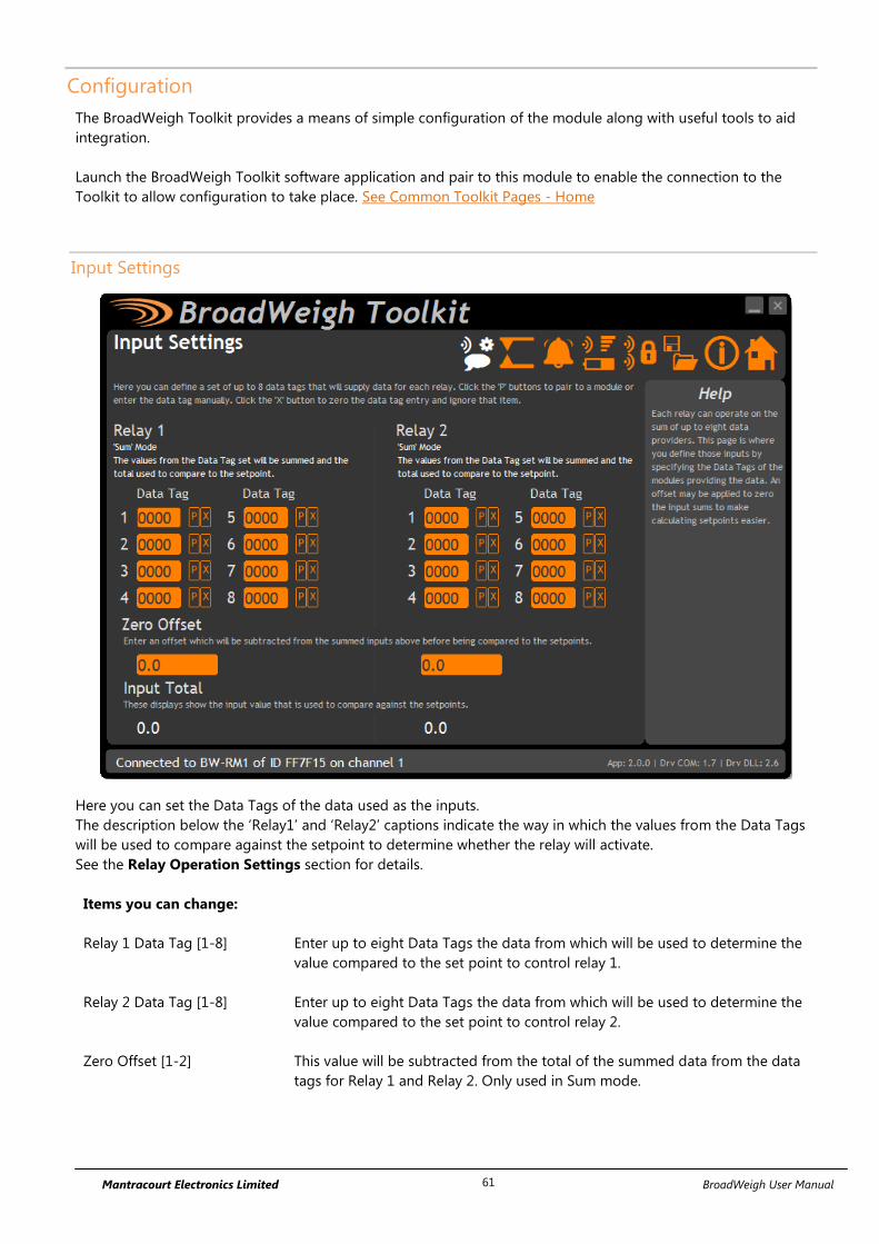
Mantracourt Electronics Limited BroadWeigh User Manual 61
Configuration
The BroadWeigh Toolkit provides a means of simple configuration of the module along with useful tools to aid
integration.
Launch the BroadWeigh Toolkit software application and pair to this module to enable the connection to the
Toolkit to allow configuration to take place. See Common Toolkit Pages - Home
Input Settings
Here you can set the Data Tags of the data used as the inputs.
The description below the ‘Relay1’ and ‘Relay2’ captions indicate the way in which the values from the Data Tags
will be used to compare against the setpoint to determine whether the relay will activate.
See the Relay Operation Settings section for details.
Items you can change:
Relay 1 Data Tag [1-8] Enter up to eight Data Tags the data from which will be used to determine the
value compared to the set point to control relay 1.
Relay 2 Data Tag [1-8] Enter up to eight Data Tags the data from which will be used to determine the
value compared to the set point to control relay 2.
Zero Offset [1-2] This value will be subtracted from the total of the summed data from the data
tags for Relay 1 and Relay 2. Only used in Sum mode.

Mantracourt Electronics Limited BroadWeigh User Manual 62
Relay Settings
Here you can change various settings that influence the operation of the individual relays.
Items you can change:
Mode [1-2] This setting determines how the Data Tag values are used to compare against
the setpoint. This is only available in firmware versions 2.0 and above. Previous
versions will operate only in ‘Sum’ mode.
Sum – The values of the defined Data Tags are summed and this
summed total is compared to the setpoint.
Any – The Data Tag with the highest value is compared to the setpoint.
i.e. If any of the individual transmitter modules exceed the setpoint.
Difference - The difference between the lowest and highest values of
all the Data Tags is calculated and this difference (Which is absolute i.e.
always positive) compared to the setpoint.
Operation [1-2] Whether set to normal or inverse decides how the relay state corresponds to
the set point and hysteresis. (See diagram on next page)
Setpoint [1-2] The Set Point is the level at which the relay state will change, see below.
Hysteresis [1-2] This value sets an offset between when the relay is energised and de-energised
creating a de-bounce for the relay. (See diagram on next page)
Latching [1-2] Latching locks the state of the relay when it passes the set point.
Advanced Button Displays the Relay Settings Advanced page.

Mantracourt Electronics Limited BroadWeigh User Manual 63
Operation and Hysteresis Settings
Relay de-energises when reaching the set point.
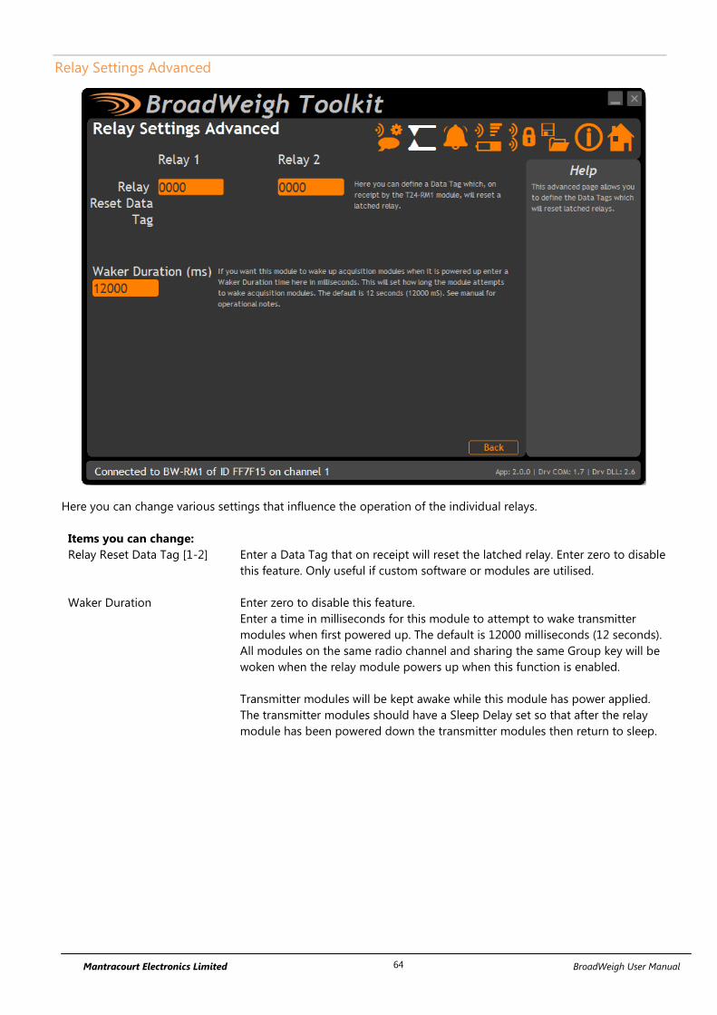
Mantracourt Electronics Limited BroadWeigh User Manual 64
Relay Settings Advanced
Here you can change various settings that influence the operation of the individual relays.
Items you can change:
Relay Reset Data Tag [1-2] Enter a Data Tag that on receipt will reset the latched relay. Enter zero to disable
this feature. Only useful if custom software or modules are utilised.
Waker Duration Enter zero to disable this feature.
Enter a time in milliseconds for this module to attempt to wake transmitter
modules when first powered up. The default is 12000 milliseconds (12 seconds).
All modules on the same radio channel and sharing the same Group key will be
woken when the relay module powers up when this function is enabled.
Transmitter modules will be kept awake while this module has power applied.
The transmitter modules should have a Sleep Delay set so that after the relay
module has been powered down the transmitter modules then return to sleep.

Mantracourt Electronics Limited BroadWeigh User Manual 65
Alarm Settings
This page defines how the individual relays will react to time outs and errors present from any defined
BroadWeigh module, as well as how Digital inputs 1 and 2 are used.
Items you can change:
Timeout Enter a time in seconds that if exceeded the BW-RM1 will affect the relay state
according to the error action, as well as set the alarm relay and light the time out LED
Error Mode The error mode defines what causes the alarm relay and individual error action to be
triggered. Errors can be defined as
Time out
Time out or Low Battery
Time out or Low Battery or Integrity Error
Error Action For each relay the action upon error detection can be defined as ;
Hold Last State
De-Energise Relay
Energise Relay
Digital Input 1 Digital input 1 can be used to either
Reset Relay 1 from its latched state
Transmit a data provider with user defined data tag containing the total of the
inputs of Relay 1
Digital Input 2 Digital input 2 can be used to either
Reset Relay 2 from its latched state
Transmit a data provider with user defined data tag containing the total of the
inputs of Relay 2

Mantracourt Electronics Limited BroadWeigh User Manual 66
Enclosure & Mounting
This module is fitted inside our large, ACM ABS enclosure. Please see Appendix A – Enclosures & Mounting –
ACM for more information.
Antennas
These modules have the antenna already fitted inside the enclosure so there are no specific mounting
requirements.

Mantracourt Electronics Limited BroadWeigh User Manual 67
Specification
Min Typical Max Units
PSU 9 - 32 Vdc
Operational Current All Relays Active 155* mA
Operational Temperature Range -10 60 °C
Storage Temperature Range -40 70 °C
Power Relays 240 V 5 A
Alarm Relay 1 A 24 Vdc 1 A 120 Vac
* At 12 V nominal Supply
Radio Range
For details of radio range please refer to Appendix B – Radio Range

Mantracourt Electronics Limited BroadWeigh User Manual 68
Base Stations & Repeater Modules
Base stations are required for configuration of the BroadWeigh modules using the BroadWeigh Toolkit software.
They are also used to supply data to PCs and PLCs.
Repeaters allow the effective radio range to be increased, allow better coverage and to divert around obstacles.
BW-BSue, BW-BSd
Overview
Base stations are the interface between the BroadWeigh radio system and a PC, PLC or other controller.
A base station would be required to configure BroadWeigh modules from a PC using the BroadWeigh Toolkit
software and also required if you are to capture data from BroadWeigh modules to a PC or PLC.
Order Codes
Base station with USB connection.
BW-BSue
Base station in weatherproof enclosure with USB
connection. This is a more robust housing with more
range than the BW-BSd.
BW-BSd
Base station mounted in a non-weatherproof USB
dongle enclosure for direct connection to laptops and
tablets.
Connections
This base station simply connects to the USB port of a PC and is powered from the USB bus.

Mantracourt Electronics Limited BroadWeigh User Manual 69
Configuration
The BroadWeigh Toolkit provides a means of simple configuration and calibration of the transmitter module
along with useful tools to aid integration.
Home
You now have successful communications with the base station so you can now let the Toolkit know you want to
configure the base station and not a remote module.
To connect to and configure the connected base station, hold the shift key and click the
Pair button.

Mantracourt Electronics Limited BroadWeigh User Manual 70
Radio Settings
Here you can change the channel and group key for the base station.
Items you can change:
Channel Select a channel between 1 and 15. The default is channel 1. You can use the
Spectrum Analyser mode to determine a good clean channel to use.
Group Key This section will only be visible if the version of the base station supports
Group keys.
Only modules with identical group keys can communicate. You can isolate
groups of modules on the same channel or just use the key to ensure the data
cannot be read by somebody else.
To use modules that support Group Keys with older modules that do not
then then the Group Keys must be blank.
Advanced See Radio Settings Advanced next
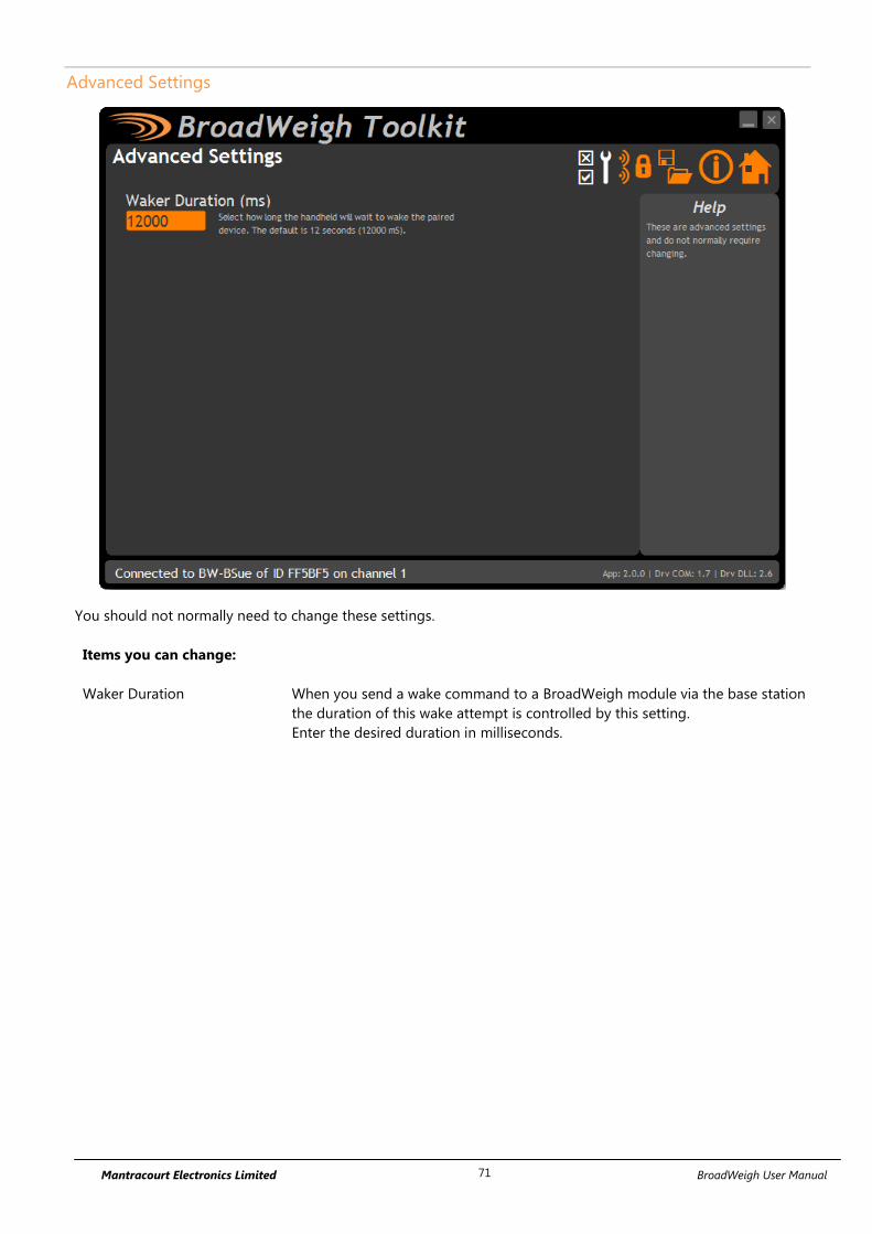
Mantracourt Electronics Limited BroadWeigh User Manual 71
Advanced Settings
You should not normally need to change these settings.
Items you can change:
Waker Duration When you send a wake command to a BroadWeigh module via the base station
the duration of this wake attempt is controlled by this setting.
Enter the desired duration in milliseconds.

Mantracourt Electronics Limited BroadWeigh User Manual 72
Enclosure & Mounting
T24-BSue
This module is fitted inside our medium enclosure. Please see Appendix A – Enclosures & Mounting – ACMi for
more information.
T24-BSd
This module is fitted inside our small enclosure. Please see Appendix A – Enclosures & Mounting – Dongle for
more information.
Antennas
These modules have the antenna already fitted inside the enclosure so there are no specific mounting
requirements.

Mantracourt Electronics Limited BroadWeigh User Manual 73
Specification
Parameter Minimu
m
Typical Maximum Units Notes
USB Supply Range 4.875 5 5.125 Vdc As defined by
USB 2.0
Specification
USB Bus Powered Operational
Current
- 100 - mA
Operating Temperature Range -20 - 55 °C
Storage Temperature Range -40 - 85 °C
Environmental Protection IP67 Does not apply to
USB connector at
cable end.
Radio Range
To determine radio range please refer to Appendix B – Radio Range
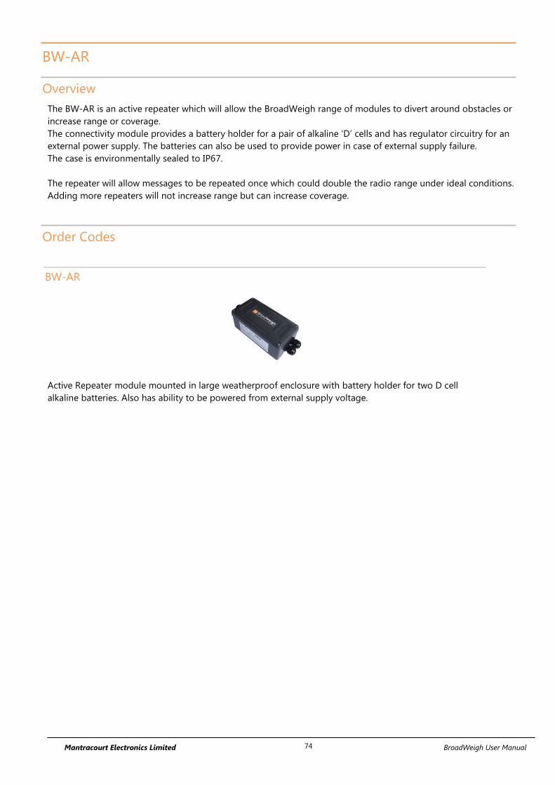
Mantracourt Electronics Limited BroadWeigh User Manual 74
BW-AR
Overview
The BW-AR is an active repeater which will allow the BroadWeigh range of modules to divert around obstacles or
increase range or coverage.
The connectivity module provides a battery holder for a pair of alkaline ‘D’ cells and has regulator circuitry for an
external power supply. The batteries can also be used to provide power in case of external supply failure.
The case is environmentally sealed to IP67.
The repeater will allow messages to be repeated once which could double the radio range under ideal conditions.
Adding more repeaters will not increase range but can increase coverage.
Order Codes
BW-AR
Active Repeater module mounted in large weatherproof enclosure with battery holder for two D cell
alkaline batteries. Also has ability to be powered from external supply voltage.
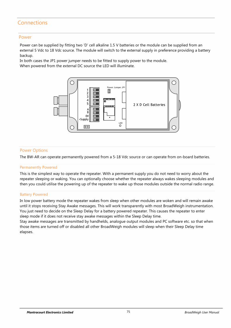
Mantracourt Electronics Limited BroadWeigh User Manual 75
Connections
Power
Power can be supplied by fitting two ‘D’ cell alkaline 1.5 V batteries or the module can be supplied from an
external 5 Vdc to 18 Vdc source. The module will switch to the external supply in preference providing a battery
backup.
In both cases the JP1 power jumper needs to be fitted to supply power to the module.
When powered from the external DC source the LED will illuminate.
2 X D Cell Batteries
AB
0V+Supply
12345
Power Jumper JP1
LED
Power Options
The BW-AR can operate permanently powered from a 5-18 Vdc source or can operate from on-board batteries.
Permanently Powered
This is the simplest way to operate the repeater. With a permanent supply you do not need to worry about the
repeater sleeping or waking. You can optionally choose whether the repeater always wakes sleeping modules and
then you could utilise the powering up of the repeater to wake up those modules outside the normal radio range.
Battery Powered
In low power battery mode the repeater wakes from sleep when other modules are woken and will remain awake
until it stops receiving Stay Awake messages. This will work transparently with most BroadWeigh instrumentation.
You just need to decide on the Sleep Delay for a battery powered repeater. This causes the repeater to enter
sleep mode if it does not receive stay awake messages within the Sleep Delay time.
Stay awake messages are transmitted by handhelds, analogue output modules and PC software etc. so that when
those items are turned off or disabled all other BroadWeigh modules will sleep when their Sleep Delay time
elapses.

Mantracourt Electronics Limited BroadWeigh User Manual 76
Getting Started
Use the BroadWeigh Toolkit to ensure that the repeater radio channel matches the rest of the BroadWeigh
modules. You will then need to decide whether the repeater is battery powered or permanently externally
powered and whether it should always wake other sleeping modules when it is powered up and awake.
Increase Range
With No
Repeater
With Repeater

Mantracourt Electronics Limited BroadWeigh User Manual 77
Span Obstacles
With No
Repeater
With Repeater
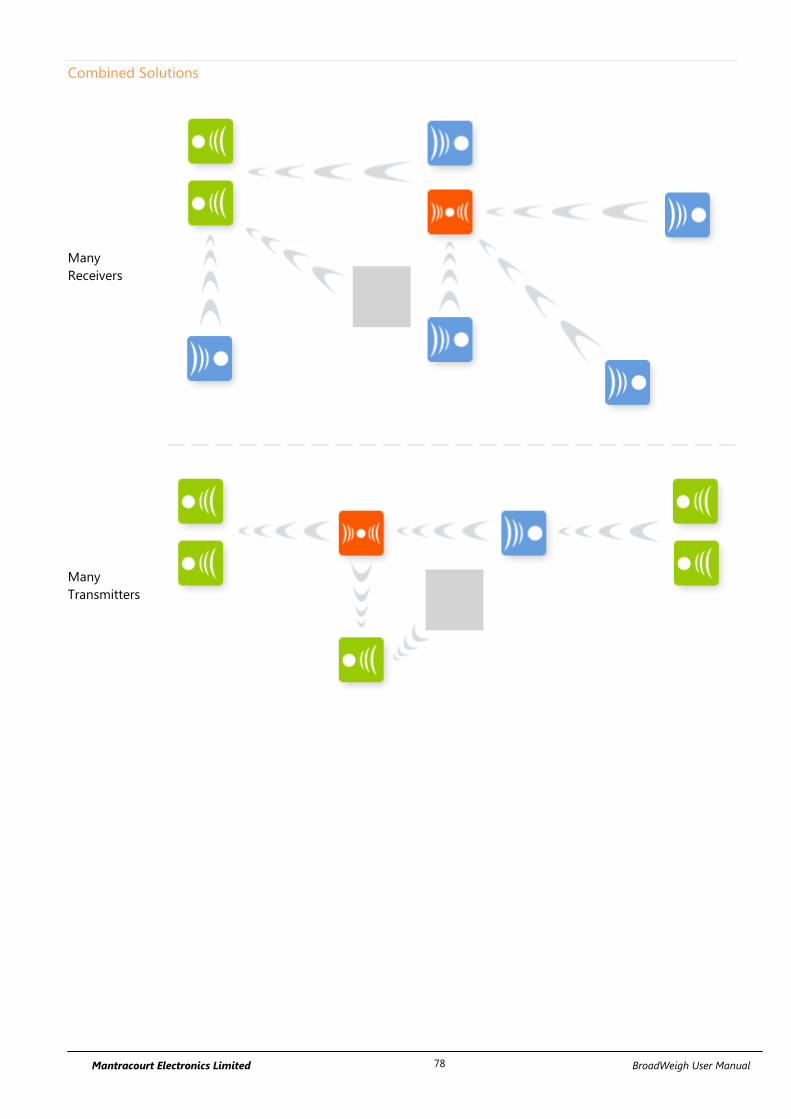
Mantracourt Electronics Limited BroadWeigh User Manual 78
Combined Solutions
Many
Receivers
Many
Transmitters

Mantracourt Electronics Limited BroadWeigh User Manual 79
Considerations
Each repeater can effectively double the amount of traffic transmitted. Be careful not to introduce too
many repeaters that are within range of each other as there may be un-necessary duplication of radio
traffic. Carefully plan the layout of radio modules to minimise this.
Using the Data Provider monitor in the BroadWeigh Toolkit can show the amount of traffic. The
BroadWeigh Toolkit on a laptop or netbook is ideal for checking installations as it is mobile so traffic can
be monitored at different points in the installation.
A repeater will not repeat a packet that has already been repeated. Hence there is only one extra ‘hop’
introduced and a maximum doubling of the radio range.
When waking remote modules separated by a repeater and that repeater is asleep it may take twice as
long to wake a module as when no repeater is involved.
If the repeater is to be battery powered use the same Sleep Delay as is suitable for the transmitter
modules in the system.
You cannot pair to a module through a repeater. Using the BroadWeigh Toolkit it may be possible to
configure module through a repeater by soft pairing. The results will vary depending on the number of
repeaters and amount of radio traffic. In some cases it may be necessary to power down repeaters when
configuring modules.
Most receiver modules and software issue a broadcast wake when turned on or activated and this will
also wake a sleeping repeater which will then proceed to wake those modules within its range..

Mantracourt Electronics Limited BroadWeigh User Manual 80
Configuration
The BroadWeigh Toolkit provides a means of simple configuration and calibration of the transmitter module
along with useful tools to aid integration.
Launch the BroadWeigh Toolkit software application and pair to this module to enable the connection to the
Toolkit to allow configuration to take place. See Common Toolkit Pages - Home
Settings
Here you can change the settings for the repeater.
Items you can change:
Always Wake In some cases where the repeater is manually powered on and off you may want it to
wake all sleeping modules within its range. Set this option to Yes to enable this. The
modules you wake should have their own Sleep Delay settings set so they go back to
sleep after stopping receiving Stay Awake messages from the data consumer (PC or
handheld).
Sleep Delay If the repeater is to be battery powered and you want to operate in low power mode
you can employ this delay. Once the repeater stops hearing Stay Awake messages
from the data consumer (PC or handheld etc.) it will go to sleep after this amount of
time. The repeater will wake when any other module is woken. Set to zero to disable.

Mantracourt Electronics Limited BroadWeigh User Manual 81
Battery Low Level Select the battery voltage below which the repeater will report a low battery.
It does this by making all repeated modules report a low battery so the data consumer
(a handheld or PC software etc.) will be able to detect a problem.
The battery level applies to the voltage seen after 3 V regulation. The default is 2.2 V
and can be left at this when the repeater is powered externally.
If the repeater is battery powered and you wish to disable this feature select 2.0 V

Mantracourt Electronics Limited BroadWeigh User Manual 82
Enclosure & Mounting
This module is fitted inside our large, ‘ACM’ ABS enclosure. Please see Appendix A – Enclosures & Mounting –
ACM for more information.
Antennas
These modules have the antenna already fitted inside the enclosure so there are no specific mounting
requirements.
Radio Range
To determine radio range please refer to Appendix B – Radio Range

Mantracourt Electronics Limited BroadWeigh User Manual 83
Specification
Environmental Min Typical Max Units
Operating temperature range -40 +85** °C
Storage temperature -40 +85 °C
Humidity 0 95 %RH
Environmental protection with suitable cables
exiting through cable glands.
IP67
**Batteries used may have reduced operating temperature range.
Power Supply Min Typical Max Units
Standby / Low power mode 5 20 µA
Normal Mode on constantly 55 60 mA
Reverse Polarity Protection -32 Vdc
Internal
Battery Supply Voltage 2.1 3 3.6 Vdc
External
Power Supply voltage 5 18 Vdc
Power Supply ripple 50 mV ac pk-pk
Battery Life Typical Units
Battery life using Duracell LR20 ‘D’
cells with the T24-AR permanently
activated. **
228 (10)
Hours (Days)
**Usually using batteries the BW-AR would be utilising the SleepDelay to return to sleep. Therefore the actual
daily usage would allow for far greater than the stated battery life. For example: If the T24-AR was used for 1 hour
per day then the battery life would be 6840 hours or 288 days or nearly 10 months.
Radio Range
To determine radio range please refer to Appendix B – Radio Range

Mantracourt Electronics Limited BroadWeigh User Manual 84
Power Supply Modules
PP1 & SP1
Overview
The Power Pack (PP1) & Solar Panel 1 (SP1) provides dependable off-grid power generation and storage to
support a variety of products.
Packaged in an IP67 sealed case with rugged waterproof connectors the PP1 has two sources of charge for the
internal battery with both solar and mains power input charging. The case also features Stainless steel padlock
protectors for easily securing your supply on site.
The PP1 has a single 12 V fuse protected output. The mating connector comes pre-fitted with 5 metres of cable
and bare end connections.
The solar panel features hail-proof tempered glass and closely packed polycrystalline cells, sealed into a robust
aluminium frame. The junction box on the rear of the panel does not protrude beyond the frame, so installation
can be simple and neat. The solar cell comes with 5 metres of cable as standard.
The SP1 & PP1 combined are designed to provide a perpetual power supply for a 12 V system drawing an
average of 53 mA, even during winter.
The PP1 can also be used as a mains powered 12 Vdc supply with 33 Ah battery backup.
Order Codes
PP1
Power pack 1 housed in robust weatherproof case.
SP1
Solar panel with cable suitable for connection to PP1

Mantracourt Electronics Limited BroadWeigh User Manual 85
Getting Started
It is important when using the PP1 in any configuration that the connections are made in the following order:
1. Connect the 12 V output lead to the device you wish to supply. The PP1 is provided with a 5 metre 12 V
output cable, this cable has the IP67 connector which mates with connection 3, see below. The cable is
bare end terminated the red wire is positive and black is ground. Ensure the bare end connections are
made before attaching to the PP1.
2. Connect the Solar Panel. The solar panel is supplied with a 5 m cable terminated with the IP67 connector
which mates with connection 1, see below.
3. Connect 100-240 Vac supply (if necessary) The PP1 is supplied with a 0.8 m mains cable with a 13 A plug.
The battery inside the PP1 will be supplied fully charged.
Power Pack 1 Connections
1. Solar Panel Input
2. 100 – 240 volt AC input
3. 12 volt DC Output
4. 6.3 amp Anti-surge Fuse
Installation
Connecting Power Pack 1
All connectors on the SP1 and PP1 are IP67 rated when correctly mated. The PP1 case is also IP67 rated meaning
it is protected against the effects of temporary immersion in water between 15 cm and 1 m for no longer than 30
minutes. Dust caps must be fitted properly if the connection is not being used. If possible avoid positioning the
PP1 in direct sunlight to limit temperature effects on the battery.
The connections for the solar panel input and 12 V output feature a locking collar to ensure the connection is
sealed. To insert remove the dust cap and align the connector and insert; there is a locating ridge to ensure
correct orientation. Once inserted, twist the collar clockwise to lock in place. The connectors for the solar panel
and 12 V output are opposite gender preventing incorrect connections.

Mantracourt Electronics Limited BroadWeigh User Manual 86
The PP1 110 - 240 Vac input has a sealing cap for when it is not connected to the mains. The sealing cap is
removed by pushing the outer sleeve towards the case and pulling the cap out.
To insert the mains cable input simply align the two parts using the locating grooves on the connector and push
in until the outer sleeve locks; to remove again repeat the same procedure as to remove the sealing cap.
Solar Panel Orientation
The SP1 is supplied on a mounting plate which when assembled with the horizontal support holds the panel at 50
degrees. The bracket is designed to be mounted on a pole or directly onto a wall.
For detailed panel angle information based on country and location see Solar Electricity Handbook calculator
here: http://www.solarelectricityhandbook.com/solar-angle-calculator.aspx

Mantracourt Electronics Limited BroadWeigh User Manual 87
When positioning the solar panel it should always face true south if you are in the northern hemisphere, or true
north if you are in the southern hemisphere. True north is not the same as magnetic north. If you are using a
compass to orient your panels, you need to correct for the difference, which varies with location. Search the web
for “magnetic declination” to find the correction for your location.
Also consider where shadows may fall on the solar panel, the panel needs maximum exposure to the sun to
operate as specified.
Operation
The PP1 and SP1 combination was designed to supply a 12 V system with a maximum continuous average current
consumption of 53 mA. The power rating of the system would be 0.636 W; if used 24 hours per day this would
equate to 15.264 watt-hours. On an average British day, this power could be produced by a solar panel array of
approximately 6 watts. However, you do of course get more power in the middle of summer than in winter. In
summer you could produce that power required with only 3 watts of solar panels. In winter you would need 15
watts of panels to produce enough power. Hence the SP1 20 W panel is more than adequate.
The output from the PP1 is fuse protected by a 6.3 A anti surge fuse, this is to protect against short circuit on the
output, fuses are 6.3 A 20x5 mm ceramic glass tube type. The 100-240 Vac input charger is fuse protected in the
13 amp plug, if this plug is replaced with any other connector please consider how your PP1 is protected.

Mantracourt Electronics Limited BroadWeigh User Manual 88
Dimensions & Weight
PP1 Dimensions
PP1 Case materials
PP1 Weight
SP1 Dimensions
SP1 Frame Material
SP1 Weight
339 x 295 x 152 mm
Polypropylene
13 kg
360 x 510 x 28 mm
Aluminium
3 kg

Mantracourt Electronics Limited BroadWeigh User Manual 89
Specifications
Electrical Min Typical Max Units
Output Voltage 12 Vdc
Internal Capacity 33 Ah
External Power Supply Voltage 100 - 250 Vac
Input Frequency 47 - 63 Hz
Cable Lengths
12 V Output Cable to Bare End 5 m
Solar Panel to Power Pack 5 m
Mains Charging cable * 0.8 m
* Supplied with 13 Amp Plug
Environmental
IP rating IP67
Operating temperature range ** -20 +50 °C
Storage temperature -20 +50 °C
Humidity 0 95 %RH
** When being charged from Mains min operating temperature 0 o
C max operating temperature is 40 oC

Mantracourt Electronics Limited BroadWeigh User Manual 90
Appendices
Appendix A - Enclosures
ACM Type
Dimensions
This ABS enclosure measures 164mm X 84mm and 57mm deep. There are three positions for cable glands; two at
one end and one at the other. Different modules may have a different number of glands fitted.
148 mm
164 mm
84
mm
50 m
m
Opening the Case
The case lid is secured with 4 x ¼ turn quick release screws. Using a flat head or Phillips screwdriver push down
and turn each screw by 90° anticlockwise to release.
Mounting Information
This enclosure is designed to be mounted to a surface. It is secured by holes on a 148 mm X 50 mm rectangle.
The mounting holes are accessible once the lid has been removed and these are outside the sealing mechanism.
Mounting holes have a diameter of 4.1 mm and can accommodate a screw head diameter of 6.8 mm.
Antenna Position
The module is fitted with a BW-ANTA antenna which is mounted on the inside of the long side of the base on the
opposite side of the enclosure to the metallised polyester label visible on the outside.
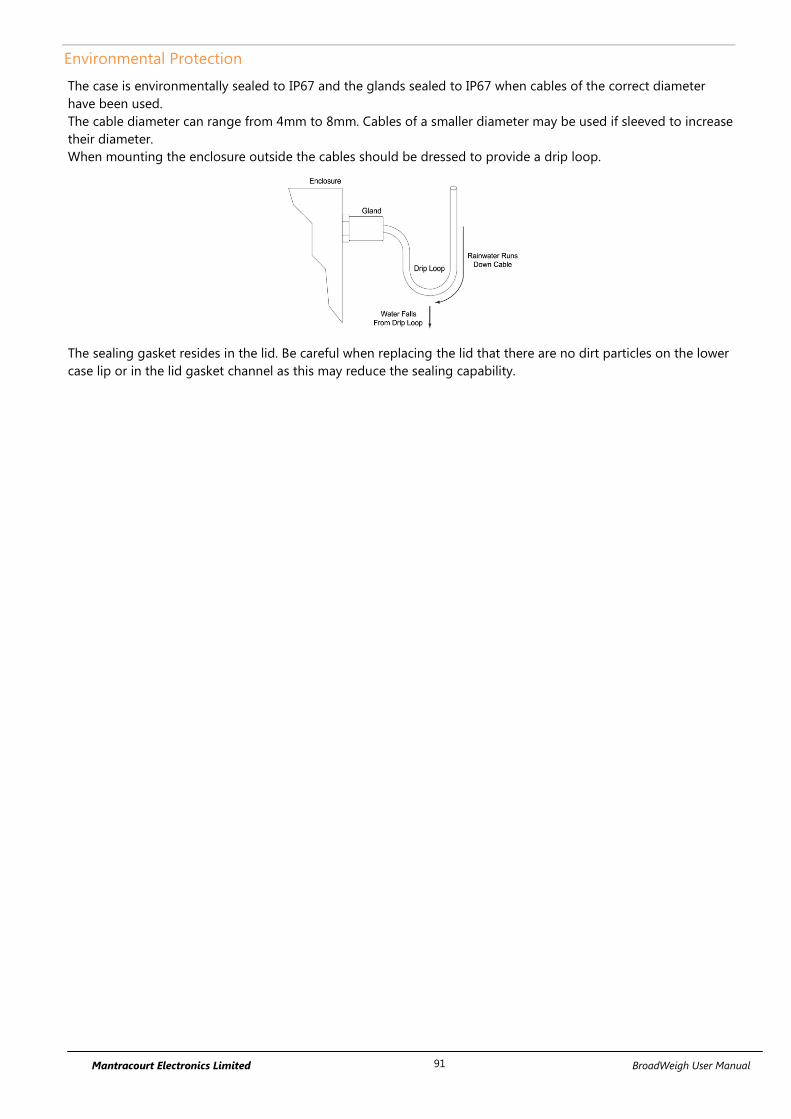
Mantracourt Electronics Limited BroadWeigh User Manual 91
Environmental Protection
The case is environmentally sealed to IP67 and the glands sealed to IP67 when cables of the correct diameter
have been used.
The cable diameter can range from 4mm to 8mm. Cables of a smaller diameter may be used if sleeved to increase
their diameter.
When mounting the enclosure outside the cables should be dressed to provide a drip loop.
The sealing gasket resides in the lid. Be careful when replacing the lid that there are no dirt particles on the lower
case lip or in the lid gasket channel as this may reduce the sealing capability.

Mantracourt Electronics Limited BroadWeigh User Manual 92
ACMi Type
Dimensions
This enclosure is 76.6 mm X 59 mm and 31 mm deep. The gland extends a further 25 mm from one long side.
Opening the Case
The case lid is secured with 4 x #2 cross head screws, remove the four screws and apply pressure in either off set
corner fixing to lift lid.
Mounting Information
The enclosure has two mounting holes as shown below; these mounting holes are external to the seal but still
covered by the case lid to offer fixings for some environmental protection. In addition mountings can be made
through the back of the case however a seal or gasket must be used to maintain environmental protection.
Antenna Position
This enclosure is fitted with a PCB antenna which sits over the wiring access chamber and is covered by the
enclosure lid.
Environmental Protection
The case is environmentally sealed to IP67.

Mantracourt Electronics Limited BroadWeigh User Manual 93
The sealing gasket resides in the base. Be careful when replacing the lid that there are no dirt particles on the
gasket channel or lid as this may reduce the sealing capability.
When mounting the enclosure outside the cables should be dressed to provide a drip loop.
The sealing gasket resides in the base. Be careful when replacing the lid that there are no dirt particles on the lid
lip or in the case gasket channel as this may reduce the sealing capability.

Mantracourt Electronics Limited BroadWeigh User Manual 94
Handheld Type
Dimensions
This ABS handheld case is 152 mm X 90 mm and 34 mm deep at its highest section.
Opening the Case
The battery compartment is secured with two Philips head screws.
Once the battery compartment has been removed this gives access to two further screws which can be removed
(along with the two at the top end) to allow the entire case to come apart. This gives access to the legend
channels where cardboard legends can be slipped in behind the transparent label windows where supported.
Note that the top two screws will have rubber ‘O’ rings on them. These rings are an integral part of the sealing
mechanism.

Mantracourt Electronics Limited BroadWeigh User Manual 95
When the case comes apart be careful of any wires running between the two case halves.
Mounting Information
There are no mounting options on the handheld enclosure.
Antenna Position
The enclosure is fitted with a BW-ANTA antenna which is mounted in the top end of the enclosure.
Environmental Protection
The enclosure is sealed to IP67. Ensure gaskets and mating parts are free from dirt and debris when re-
assembling.
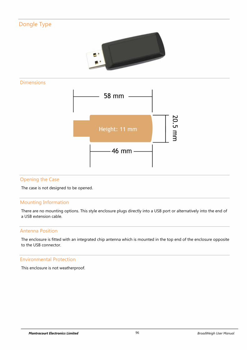
Mantracourt Electronics Limited BroadWeigh User Manual 96
Dongle Type
Dimensions
Opening the Case
The case is not designed to be opened.
Mounting Information
There are no mounting options. This style enclosure plugs directly into a USB port or alternatively into the end of
a USB extension cable.
Antenna Position
The enclosure is fitted with an integrated chip antenna which is mounted in the top end of the enclosure opposite
to the USB connector.
Environmental Protection
This enclosure is not weatherproof.

Mantracourt Electronics Limited BroadWeigh User Manual 97
Appendix B – Radio Range
Overview
Radio performance at microwave wavelengths is very dependent upon the operating environment; any structure
within the operating region of the radios will give rise to three effects:
Obscuration. Obscuration will result in reduced range and occurs when an obstruction masks the line-of-sight
between radios.
Aberrations to the horizontal and vertical space patterns. Distortion of these patterns may occur if structures
or objects are placed in the near or intermediate field of the antenna. The effect will be to distort the coverage
patterns, adversely affecting range and link quality.
Reflection. Any object placed in line-of-sight of the transmit antenna will result in signals arriving at the receiver
by an indirect path. Degradation of performance due to reflection (multipath effects) appears as reduced range or
poor link quality.
Any of the above will cause poor RSSI figures, an increase in the packet loss rate and in extreme cases complete
loss of signal. Fortunately, if consideration is given to these effects at the integration stage then a good quality
link will be obtained.
Guidelines for installation:
When planning installations ensure that line-of–sight between nodes is maintained and that objects or structures
are kept at least one metre away from antennae wherever possible.
Range
Radio range has been measured as 800 m line of sight in an open field site where the transmitter was 3 m from
the ground and the receiver was 1.5 m from the ground.
This range will be reduced when transmitters or receivers are close to metallic structures or close to the ground.
Walls and floors will also reduce the achievable range in indoor environments.
BW-BSd has a range of 500 m
Modules manufactured before July 2015 have a range of 200 m.

Mantracourt Electronics Limited BroadWeigh User Manual 98
Appendix C - Radio Specification The following specification applies to all BroadWeigh modules.
Min Typical Max Units
License License Exempt
Modulation method MS (QPSK)
Radio type Transceiver (2 way)
Data rate 250 k bits/sec
Radio Frequency 2.4000 2.4835 GHz
Power 10 mW
Channels (DSSS) 15
For radio range information See Appendix B – Antenna Range

Mantracourt Electronics Limited BroadWeigh User Manual 99
Appendix D – Intentionally Empty

Mantracourt Electronics Limited BroadWeigh User Manual 100
Appendix E – Approval Statements
CE
Complies with EMC directive. 2014/30/EU The Radio Equipment Directive,2014/53/EU,
European Community, Switzerland, Norway, Iceland, and Liechtenstein
English: This equipment is in compliance with the essential requirements and other relevant provisions of Directive 1999/5/EC.
Deutsch: Dieses Gerät entspricht den grundlegenden Anforderungen und den weiteren entsprecheneden
Vorgaben der Richtlinie 2014/53/EU.
Dansk: Dette udstyr er i overensstemmelse med de væsentlige krav og andre relevante bestemmelser i Directiv
2014/53/EU.
Español: Este equipo cumple con los requisitos esenciales asi como con otras disposiciones de la Directive
2014/53/EU.
Français: Cet appareil est conforme aux exigencies essentialles et aux autres dispositions pertinantes de la
Directive 2014/53/EU.
Íslenska: Þessi búnaður samrýmist lögboðnum kröfum og öðrum ákvæðum tilskipunar 2014/53/EU.
Italiano: Questo apparato é conforme ai requisiti essenziali ed agli altri principi sanciti dalla Direttiva 2014/53/EU.
Nederlands: Deze apparatuur voldoet aan de belangrijkste eisen en andere voorzieningen van richtlijn 2014/53/EU.
Norsk: Dette utstyret er i samsvar med de grunnleggende krav og andre relevante bestemmelser i EU-directiv
2014/53/EU.
Português: Este equipamento satisfaz os requisitos essenciais e outras provisões da Directiva 2014/53/EU.
Suomalainen: Tämä laite täyttää direktiivin 2014/53/EU oleelliset vaatimukset ja on siinä asetettujen muidenkin ehtojen
mukainen.
Svenska: Denna utrustning är i överensstämmelse med de väsentliga kraven och andra relevanta bestämmelser i
Direktiv 2014/53/EU.
This equipment is in compliance with the essential requirements and other relevant provisions of Directive 2014/53/EU.
Manufactured in the UK by: Mantracourt Electronics Ltd, The Drive, Farringdon, Exeter, Devon, EX5 2JB, UK

Mantracourt Electronics Limited BroadWeigh User Manual 101
IC
IC:7224A-RA24
This device complies with Industry Canada licence-exempt RSS standard(s). Operation is subject to the following two
conditions: (1) this device may not cause interference, and (2) this device must accept any interference, including
interference that may cause undesired operation of the device.
Under Industry Canada regulations, this radio transmitter may only operate using an antenna of a type and maximum
(or lesser) gain approved for the transmitter by Industry Canada. To reduce potential radio interference to other users,
the antenna type and its gain should be so chosen that the equivalent isotropically radiated power (e.i.r.p.) is not more
than that necessary for successful communication.
This radio transmitter RA24 has been approved by Industry Canada to operate with the antenna types listed below with
the maximum permissible gain and required antenna impedance for each antenna type indicated. Antenna types not
included in this list, having a gain greater than the maximum gain indicated for that type, are strictly prohibited for use
with this device.
Antenna Gain (dBi) Antenna Type Manufacturer/Vendor
Ant A 3 Inverted F Mantracourt
Ant C 2.2 ½ wave Dipole Mantracourt
Integrated 1.3 Chip antenna Mantracourt
To comply with Industry Canada RF radiation exposure limits for general population, the antenna(s) used for
this transmitter must be installed such that a minimum separation distance of 5 cm is maintained between the
radiator (antenna) and all persons at all times and must not be co-located or operating in conjunction with any
other antenna or transmitter.
Manufactured in the UK by: Mantracourt Electronics Ltd, The Drive, Farringdon, Exeter, Devon, EX5 2JB, UK

Mantracourt Electronics Limited BroadWeigh User Manual 102
FCC
Family: RA24
Models: i and e
FCC ID:VHARA24
This device complies with Part 15 of the FCC Rules.
Operation is subject to the following two conditions:
(1) This device may not cause harmful interference, and
(2) This device must accept any interference received, including interference that may cause undesired operation.
This equipment complies with FCC radiation exposure limits set forth for an uncontrolled environment. End users
must follow the specific operating instructions for satisfying RF exposure compliance. This transmitter must not
be co-located or operating in conjunction with any other antenna or transmitter.
Changes or modifications not expressly approved by the party responsible for compliance could void the user's
authority to operate the equipment
For use with antennas: integrated, T24-ANTA, T24-ANTB, T24-ANTC, T24-ANTD, T24-ANTE antennas and those
listed in the table below.
Manufacturer Code Description Gain Available From
DELTA7A
Dual band 2.4 or 5.8GHz
Hinged mount whip
2.1dBi Sequoia
DELTA14 Stubby WiFi / WLAN Antenna
2.0dBi Sequoia
DELTA15/SMAM/RA/RP11
2.4GHz Right angle RPSMA
2.0dBi
Sequoia
1699481 AUREL ANT.RP SMA 2.4GHz 2.0dBi Farnell Electronic
Components
537-785 EAD, FBKR35068-RS-KR WiFi Antenna 2.0dBi RS Components
Manufactured in the UK by: Mantracourt Electronics Ltd, The Drive, Farringdon, Exeter, Devon, EX5 2JB, UK

Mantracourt Electronics Limited BroadWeigh User Manual 103
Appendix F - OEM / Reseller Marking and Documentation
Requirements
CE
The T24 series has been certified for several European countries.
If the transmitter module is incorporated into a product, the manufacturer must ensure compliance of the final
product to the European harmonized EMC and low-voltage/safety standards. A Declaration of Conformity must
be issued for each of these standards and kept on file as described in Annex II of the R&TTE Directive.
Furthermore, the manufacturer must maintain a copy of the T24 device user manual documentation and ensure
the final product does not exceed the specified power ratings, antenna specifications, and/or installation
requirements as specified in the user manual. If any of these specifications are exceeded in the final product, a
submission must be made to a notified body for compliance testing to all required standards.
OEM Labelling Requirements
The ‘CE’ marking must be affixed to a visible location on the OEM product.
The CE mark shall consist of the initials “CE” taking the following form:
If the CE marking is reduced or enlarged, the
proportions given in the above drawing must be
respected.
The CE marking must have a height of at least 5 mm
except where this is not possible on account of the
nature of the apparatus.
The CE marking must be affixed visibly, legibly, and
indelibly.

Mantracourt Electronics Limited BroadWeigh User Manual 104
IC
The RA24 Module has been certified for integration into products only by OEM integrators under the following
conditions:
1. The antenna(s) must be installed such that a minimum separation distance of 5cm is maintained between
the radiator (antenna) and all persons at all times.
2. The transmitter module must not be co-located or operating in conjunction with any other antenna or
transmitter.
As long as the two conditions above are met, further transmitter testing will not be required. However, the OEM
integrator is still responsible for testing their end-product for any additional compliance requirements required
with this module installed (for example, digital device emissions, PC peripheral requirements, etc.).
IMPORTANT NOTE: In the event that these conditions cannot be met (for certain configurations or co-location
with another transmitter), then Industry Canada certification is no longer considered valid and the IC Certification
Number cannot be used on the final product. In these circumstances, the OEM integrator will be responsible for
re-evaluating the end product (including the transmitter) and obtaining a separate Industry Canada authorization.
End Product Labelling
The RA24 Module is labelled with its own IC Certification Number. If the IC Certification Number is not visible
when the module is installed inside another device, then the outside of the device into which the module is
installed must also display a label referring to the enclosed module. In that case, the final end product must be
labelled in a visible area with the following:
Contains Model RA24 Radio (2.4 GHz), IC:7224A-RA24
The OEM of the RA24 Module must only use the approved antenna(s) listed above, which have been certified with
this module.
The OEM integrator has to be aware not to provide information to the end user regarding how to install or
remove this RF module or change RF related parameters in the user’s manual of the end product.
The user’s manual for the end product must include the following information in a prominent location:
“To comply with Industry Canada RF radiation exposure limits for general population, the antenna(s) used
for this transmitter must be installed such that a minimum separation distance of 5 cm is maintained
between the radiator (antenna) and all persons at all times and must not be co-located or operating in
conjunction with any other antenna or transmitter.”
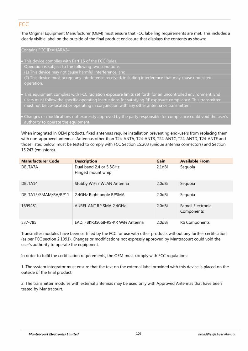
Mantracourt Electronics Limited BroadWeigh User Manual 105
FCC
The Original Equipment Manufacturer (OEM) must ensure that FCC labelling requirements are met. This includes a
clearly visible label on the outside of the final product enclosure that displays the contents as shown:
Contains FCC ID:VHARA24
This device complies with Part 15 of the FCC Rules.
Operation is subject to the following two conditions:
(1) This device may not cause harmful interference, and
(2) This device must accept any interference received, including interference that may cause undesired
operation.
This equipment complies with FCC radiation exposure limits set forth for an uncontrolled environment. End
users must follow the specific operating instructions for satisfying RF exposure compliance. This transmitter
must not be co-located or operating in conjunction with any other antenna or transmitter.
Changes or modifications not expressly approved by the party responsible for compliance could void the user's
authority to operate the equipment
When integrated in OEM products, fixed antennas require installation preventing end-users from replacing them
with non-approved antennas. Antennas other than T24-ANTA, T24-ANTB, T24-ANTC, T24-ANTD, T24-ANTE and
those listed below, must be tested to comply with FCC Section 15.203 (unique antenna connectors) and Section
15.247 (emissions).
Manufacturer Code Description Gain Available From
DELTA7A
Dual band 2.4 or 5.8GHz
Hinged mount whip
2.1dBi Sequoia
DELTA14 Stubby WiFi / WLAN Antenna
2.0dBi Sequoia
DELTA15/SMAM/RA/RP11
2.4GHz Right angle RPSMA
2.0dBi
Sequoia
1699481 AUREL ANT.RP SMA 2.4GHz 2.0dBi Farnell Electronic
Components
537-785 EAD, FBKR35068-RS-KR WiFi Antenna 2.0dBi RS Components
Transmitter modules have been certified by the FCC for use with other products without any further certification
(as per FCC section 2.1091). Changes or modifications not expressly approved by Mantracourt could void the
user’s authority to operate the equipment.
In order to fulfil the certification requirements, the OEM must comply with FCC regulations:
1. The system integrator must ensure that the text on the external label provided with this device is placed on the
outside of the final product.
2. The transmitter modules with external antennas may be used only with Approved Antennas that have been
tested by Mantracourt.

Mantracourt Electronics Limited BroadWeigh User Manual 106
Appendix G - Worldwide Regional Approvals
Region Product Conforms To
Europe CE
USA FCC
Canada IC
Important Note
Mantracourt does not list the entire set of standards that must be met for each country. Mantracourt customers
assume full responsibility for learning and meeting the required guidelines for each country in their distribution
market.
For more information relating to European compliance of an OEM product incorporating the T24 or BroadWeigh
range of modules, contact Mantracourt, or refer to the following web site: www.ero.dk

Mantracourt Electronics Limited BroadWeigh User Manual 107
Appendix H - Declaration of Conformity
EU DECLARATION OF CONFORMITY
We, the undersigned:
Name of Manufacturer: Mantracourt Electronics Ltd
Address: The Drive, Farrington, Exeter,
Devon, EX5 2JB
Country: United Kingdom
Declare under our sole responsibility that the Broadweigh Product Range is in conformity
with the following relevant Union harmonisation legislation:
LVD Directive 2014/35/EU
EMC Directive 2014/30/EU
RoHS Directive 2011/65/EU
Radio Equipment Directive 2014/53/EU
Machinery Directive 2006/42/EC
Based on the following harmonised standards:
EN 61326-1:2013
EN 61326-2-3:2013
EN 61010-1:2010
EN 300328 V2.1.1
Name and position of person binding the manufacturer or authorised representative:
Signed
Name: Robert Willmington-Badcock
Function: Managing Director
Location: Mantracourt Electronics Ltd
Date of issue: 18th
October 2017
FCC ID: VHARA24 IC:7224A-RA24

Mantracourt Electronics Limited BroadWeigh User Manual 108
Appendix I - Warranty
Warranty
All Telemetry products from Mantracourt Electronics Ltd.,
('Mantracourt') are warranted against defective material and
workmanship for a period of one (1) year from the date of dispatch.
If the 'Mantracourt' product you purchase appears to have a defect in
material or workmanship or fails during normal use within the period,
please contact your Distributor, who will assist you in resolving the
problem. If it is necessary to return the product to 'Mantracourt' please
include a note stating name, company, address, phone number and a
detailed description of the problem. Also, please indicate if it is a
warranty repair.
The sender is responsible for shipping charges, freight insurance and
proper packaging to prevent breakage in transit.
'Mantracourt' warranty does not apply to defects resulting from action
of the buyer such as mishandling, improper interfacing, operation
outside of design limits, improper repair or unauthorised modification.
No other warranties are expressed or implied. 'Mantracourt' specifically
disclaims any implied warranties of merchantability or fitness for a
specific purpose.
The remedies outlined above are the buyer’s only remedies.
'Mantracourt' will not be liable for direct, indirect, special, incidental or
consequential damages whether based on the contract, tort or other
legal theory.
Any corrective maintenance required after the warranty period should
be performed by 'Mantracourt' approved personnel only.

Mantracourt Electronics Limited BroadWeigh User Manual 109
Document Title: BroadWeigh User Manual
Applies To: BroadWeigh Product Range
Part Number: 517-927
Issue Number: 03.02
Dated: 18th October 2017
In the interests of continued product development, Mantracourt Electronics Limited
reserves the right to alter product specifications without prior notice.
www.mantracourt.com


![T24 Technical Manual - · PDF fileT24-BSi and T24-BSu [Base Station] ... Mantracourt Electronics Limited T24 Technical Manual 4 ... RF Exposure Limits](https://static.fdocuments.in/doc/165x107/5a809fa07f8b9aa24f8c9617/t24-technical-manual-and-t24-bsu-base-station-mantracourt-electronics-limited.jpg)

