Broadband Terminated Vee Beam Wire Antenna - · PDF fileBroadband Terminated Vee Beam Wire...
17
Broadband Terminated Vee Beam Wire Antenna TEN-TEC Model 3402 and 3403 1.8-54 or 3.5-54 MHz. THROW AWAY YOUR ANTENNA TUNER ! Models 3402 and 3403 are broadband terminated vee beam wire antennas. These broadband HF antennas are small size and offer continuous coverage from 1.8 to 54 MHz ( 200ft) or 3.5 to 54 MHz ( 100ft) with VSWR of below 2:1 up to 30 MHz and below 2.5:1 from 30 to 54 MHz (typical VSWR on HF frequencies is 1.4:1). Well-suited to the amateur who has a small lot and needs a broadband antenna for full frequency coverage! In the vee-beam configuration, the antenna is unidirectional and offers significant gain at higher frequencies. In the broadside/end-fire configuration (installed similar to a traditional inverted-V dipole) the antenna is bi-directional or multi-directional, depending on frequency of operation. Broadband vee-beam offers a number of advantages over a typical flat-top multiband dipole or windom. First, continuous frequency coverage presents a low VSWR to your transceiver. This multiband wire dipole antennas does not require the use of an antenna tuner on one or more HF bands. MARS operators do not need to employ another antenna for ham bands vs. MARS coverage; the vee-beam will cover both. Third, because the antenna does not require a traditional flat-top dipole or inverted-V style installation, a more limited space can be utilized for installation of the antenna in the vee-beam configuration. The 200ft model covers 1.8-54 MHz and is 100 ft. per side. Model 100ft model covers 3.5-54 MHz and is only 50ft. per side! All the user needs to add is rope for support, a coax feedline, and either two ground rods or two radials depending on the desired installation configuration. From NNN0EPY/WB8MWG: Several years ago,I was looking to a good all band Antenna that I could add to my collection of wires in the backyard. I run a NDN/RDN Pactor BBS on 4.7 5.8 and 7.9 MHz. Three HF radios operating 24/7 Pactor running 50 watts each on home made double bazooka dipoles. So, whatever antenna I add must get along with the others that I have on site. When talking with Bo NNN0ZLS about my situation, he recommended the Ten-Tec Antennas that he was running at two locations.
Transcript of Broadband Terminated Vee Beam Wire Antenna - · PDF fileBroadband Terminated Vee Beam Wire...
Broadband Terminated Vee Beam Wire Antenna TEN-TEC Model 3402 and 3403
1.8-54 or 3.5-54 MHz.
THROW AWAY YOUR ANTENNA TUNER !
Models 3402 and 3403 are broadband terminated vee beam wire antennas. These broadband HF antennas are small size and offer continuous coverage from 1.8 to 54 MHz ( 200ft) or 3.5 to 54 MHz ( 100ft) with VSWR of below 2:1 up to 30 MHz and below 2.5:1 from 30 to 54 MHz (typical VSWR on HF frequencies is 1.4:1). Well-suited to the amateur who has a small lot and needs a broadband antenna for full frequency coverage!
In the vee-beam configuration, the antenna is unidirectional and offers significant gain at higher frequencies. In the broadside/end-fire configuration (installed similar to a traditional inverted-V dipole) the antenna is bi-directional or multi-directional, depending on frequency of operation.
Broadband vee-beam offers a number of advantages over a typical flat-top multiband dipole or windom. First, continuous frequency coverage presents a low VSWR to your transceiver. This multiband wire dipole antennas does not require the use of an antenna tuner on one or more HF bands.
MARS operators do not need to employ another antenna for ham bands vs. MARS coverage; the vee-beam will cover both. Third, because the antenna does not require a traditional flat-top dipole or inverted-V style installation, a more limited space can be utilized for installation of the antenna in the vee-beam configuration.
The 200ft model covers 1.8-54 MHz and is 100 ft. per side. Model 100ft model covers 3.5-54 MHz and is only 50ft. per side! All the user needs to add is rope for support, a coax feedline, and either two ground rods or two radials depending on the desired installation configuration.
From NNN0EPY/WB8MWG:
Several years ago,I was looking to a good all band Antenna that I could add to my collection of wires in the backyard. I run a NDN/RDN Pactor BBS on 4.7 5.8 and 7.9 MHz.
Three HF radios operating 24/7 Pactor running 50 watts each on home made double bazooka dipoles.
So, whatever antenna I add must get along with the others that I have on site.
When talking with Bo NNN0ZLS about my situation, he recommended the Ten-Tec Antennas that he was running at two locations.

Bo said” I use my 200 foot 1.8-30 version more in NVIS mode at home. I run it as my ALE antenna from 2 to 27 MHz with no tuner. The center height is about 20 feet while the ends are at 8 feet or less running to ground rods. This pseudo-NVIS arrangement allows good all-around coverage on the lower frequencies while the higher frequencies approach 1/4 wavelength over ground. I also use the 3.5 to 30 MHz version as my antenna for the 5 MHz ADN message switch. I run this one with a center height of 30 feet with the ends at 6-8 feet with ground rods. With no tuner, it does not require fussing with an antenna tuner as rain, snow and ice hit the antenna”.
I did some research and found one on Ebay and bought it.
I installed it in an inverted Vee configuration off the side of a 60 ft tower on the opposite side of the three antennas for the BBS, in a 45 degree spread, terminating into, two ten ft poles mounted 87 ft from the base of the tower. At the base of the 10 ft poles are two 8 ft ground rods for each pole.
How does it work? Super! NO Tuner and in the Winter when the band goes long we are still on the air. 160 meter SSB is great also. It will work from 1.8 thru 54 MHz.
I get very little to no intermod with the other radios. I do have BPF filters cut for each frequency installed in the coaxial lines of each BBS antenna.
I wanted another TEN-TEC 3402, and found out that TEN-TEC no longer sells or manufactures these units.
So, I did some testing with the one I owned and found the Balun is 16:1 and the termination resistors are approximately 400 Ohms.
I found the 16:1 balun at Wireman http://thewireman.com/baluns.html ,
I bought one ready made and one in kit form.
830
CQ Toroidal, full power, 1 - 28 MHz, 1:1 to 16:1 ratios, voltage type. Kit contains 20 ft 200 deg. C enameled soft copper wire, T-200-1 iron powder core, 3 ft fiberglass tape, instructions, reference.
$14.50 Kit or
$38 Assembled
It was easier for me to look at one ready made unit and copy it than read the instructions.
I also took some pictures for future use.
Before doing this report, I called TEN-TEC and received their Blessing.

They asked that I send them a copy of this report.
The TEN-TEC Company people are super to work with.
I have a copy of the TEN-TEC pdf instructions that came with my unit that I will pass along.
Technical specifications:
Input power rating: 250 watts ICAS, 100 watts continuous duty. This depends on the wattage of the resistors.
Feed point impedance: 50 ohms nominal
Feed point VSWR: model 200, less than 2:1typical 1.8-30 MHz, 2.5:1 30-54 MHz. Model 100 less than 2:1 typical 3.5-30 MHz, 2.5:1 30-54 MHz.
Transformer impedances: 50 ohms feed point, 800 ohms antenna.
16:1 Balun, these can be made or purchased from “The wireman”
Termination impedance: 400 ohms typical
These I scrounged at a Ham swap. 380 ohms to 420 ohms NON-INDUCTIVE will work.
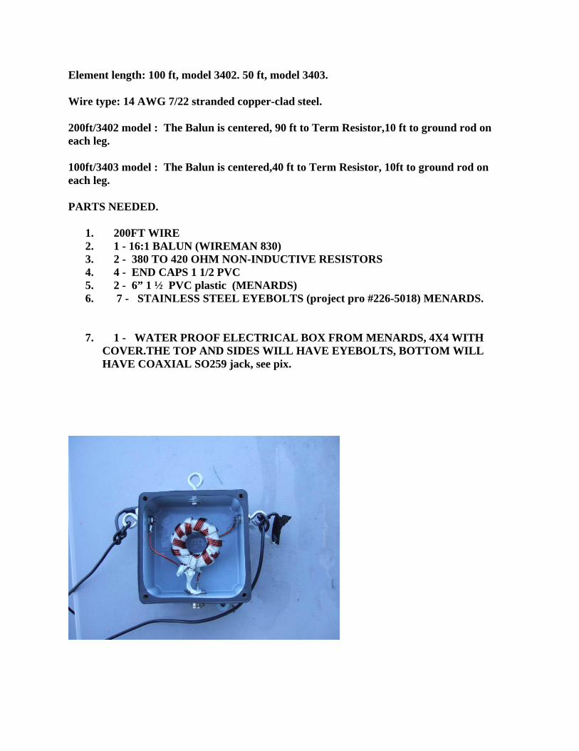
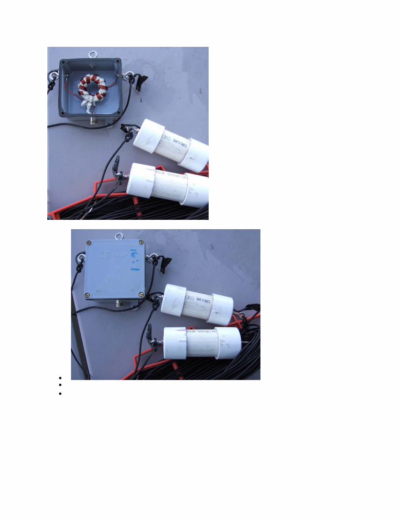
I mounted them in a short 1 1/2 PVC 6” long with end cap. Also Stainless Steel eyebolts ( Menards). Drill two holes in the end caps, one center for “I” bolts, one offset for wire.
On the Termination Resistors, solder a short insulated wire on each end about 6” long.
Install the eye bolts in the center hole of the end caps. Use extra nuts and washers to secure.
Install the resistor in the PVC and feed a wire out the offset hole, glue the ends caps.
You now have a very weather proof unit.
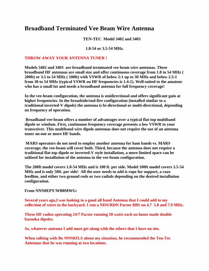
I mounted the 16:1 Balun in a weather proof 4x4 electrical box, again Menards .
Element length: 100 ft, model 3402. 50 ft, model 3403.
Wire type: 14 AWG 7/22 stranded copper-clad steel.
200ft/3402 model : The Balun is centered, 90 ft to Term Resistor,10 ft to ground rod on each leg.
100ft/3403 model : The Balun is centered,40 ft to Term Resistor, 10ft to ground rod on each leg.
PARTS NEEDED.
1. 200FT WIRE 2. 1 - 16:1 BALUN (WIREMAN 830) 3. 2 - 380 TO 420 OHM NON-INDUCTIVE RESISTORS 4. 4 - END CAPS 1 1/2 PVC 5. 2 - 6” 1 ½ PVC plastic (MENARDS) 6. 7 - STAINLESS STEEL EYEBOLTS (project pro #226-5018) MENARDS.
7. 1 - WATER PROOF ELECTRICAL BOX FROM MENARDS, 4X4 WITH COVER.THE TOP AND SIDES WILL HAVE EYEBOLTS, BOTTOM WILL HAVE COAXIAL SO259 jack, see pix.
• • •

1
Ten-Tec Model 3402 and 3403 Broadband AntennasInstallation and Operation Manual
PN 74393
1. Introduction
The Ten-Tec Model 3402 Broadband Terminated Vee Beam Antenna offerscontinuous coverage between 1.8 and 30 MHz with a maximum VSWR of 2:1—typically1.4:1 or less. The Model 3403 is a shorter version of the antenna that covers 3.5 to 30MHz with a maximum VSWR of 2:1—typically 1.4:1 or less. For both models, VHFcoverage is also provided for with a maximum VSWR of 2.5:1 from 30 to 54 MHz. Theantennas handle 100 W in continuous-duty operation and 250 W intermittent commercialand amateur service (ICAS). It may be installed in several different configurations,offering a flexible approach to broadband frequency coverage. The antennas aredelivered fully assembled. No tuning or adjustment is required.
In the vee-beam configuration, the antenna is unidirectional and offers significantgain at the higher frequencies. In the broadside/endfire configuration, the antenna isbidirectional or multi-directional, depending on frequency of operation. Typical radiationpatterns are presented in Section 3.
Refer to Fig 1-1. Models 3402 and 3403 may be installed using a single mast.The antenna consists of a 50-to-800 ohm broadband transformer, two 100-foot radiatingelements (50-foot elements for Model 3403), two terminations and two wire segments forconnection to ground.

2
Fig 1-1: Model 3402 typical installation.
A. Brief Theory of Operation
Models 3402 and 3403 are nonresonant, travelling-wave antennas. That meansthat at any one position along a radiating element, values of current and voltage are notfixed, as they are in a standing-wave antenna, such as a resonant dipole. The antennaexploits a property of endfed wires one wavelength and longer: they exhibit gain at someangle to the axis of the wire and on each side of the wire, both fore and aft. A long wirethus has four major lobes in its radiation pattern and two or more minor lobes. See Fig 1-2. When an endfed wire is many wavelengths long, the directions of maximum radiationapproach the axis of the wire.
Fig 1-2. End-fed long-wire radiation pattern.
When two long wires form a vee and are fed in balanced fashion at the apex, pairs ofmajor radiation lobes tend to reinforce, producing a single major lobe in each directionalong a line bisecting the vee. See Fig 1-3.
Placing terminations to ground at the free end of each wire eliminates reflectedwaves from those ends, making the antenna broadband. Radiated energy comes onlyfrom the waves that travel from the feed point to the terminations. The terminationstherefore also make the antenna unidirectional. See Fig 1-4.

3
Fig 1-3. Unterminated, vee beam radiation pattern.
Fig 1-4. Terminated vee-beam radiation pattern.
4
The angle between the radiating elements is called the apex angle. The optimumapex angle depends on frequency. Apex angle may be optimized for a single frequencyor a compromise reached for a group of very different frequencies.
Takeoff angle is the angle with respect to ground (altitude) at which maximumradiation occurs. With this and most other antennas, takeoff angle depends oninstallation height above ground.
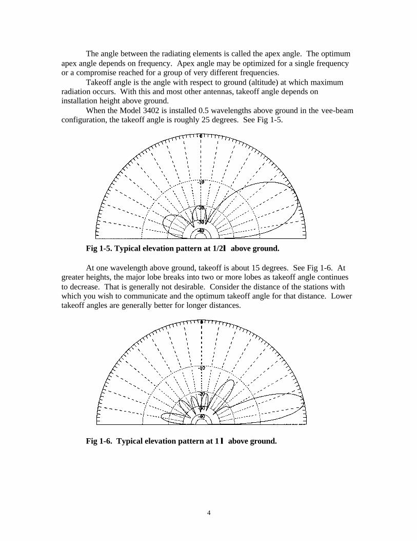
When the Model 3402 is installed 0.5 wavelengths above ground in the vee-beamconfiguration, the takeoff angle is roughly 25 degrees. See Fig 1-5.
Fig 1-5. Typical elevation pattern at 1/2λλ above ground.
At one wavelength above ground, takeoff is about 15 degrees. See Fig 1-6. Atgreater heights, the major lobe breaks into two or more lobes as takeoff angle continuesto decrease. That is generally not desirable. Consider the distance of the stations withwhich you wish to communicate and the optimum takeoff angle for that distance. Lowertakeoff angles are generally better for longer distances.
Fig 1-6. Typical elevation pattern at 1 λλ above ground.
5
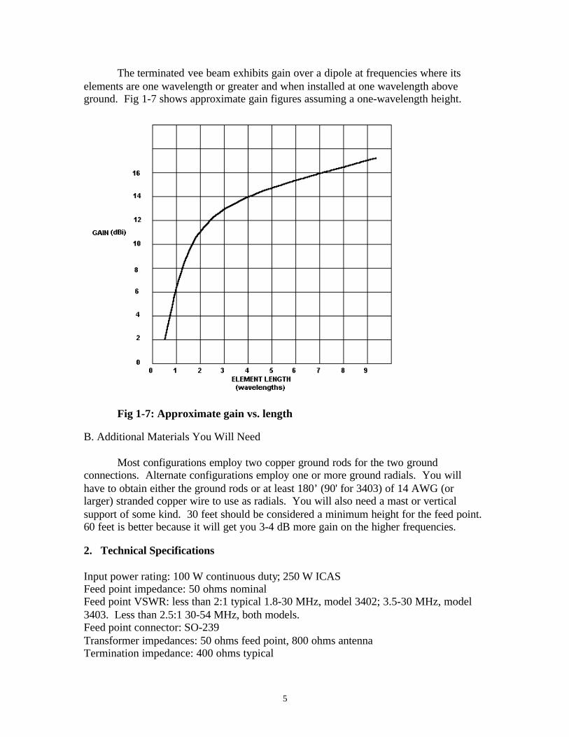
The terminated vee beam exhibits gain over a dipole at frequencies where itselements are one wavelength or greater and when installed at one wavelength aboveground. Fig 1-7 shows approximate gain figures assuming a one-wavelength height.
Fig 1-7: Approximate gain vs. length
B. Additional Materials You Will Need
Most configurations employ two copper ground rods for the two groundconnections. Alternate configurations employ one or more ground radials. You willhave to obtain either the ground rods or at least 180’ (90' for 3403) of 14 AWG (orlarger) stranded copper wire to use as radials. You will also need a mast or verticalsupport of some kind. 30 feet should be considered a minimum height for the feed point.60 feet is better because it will get you 3-4 dB more gain on the higher frequencies.
2. Technical Specifications
Input power rating: 100 W continuous duty; 250 W ICASFeed point impedance: 50 ohms nominalFeed point VSWR: less than 2:1 typical 1.8-30 MHz, model 3402; 3.5-30 MHz, model3403. Less than 2.5:1 30-54 MHz, both models.Feed point connector: SO-239Transformer impedances: 50 ohms feed point, 800 ohms antennaTermination impedance: 400 ohms typical

6
Element length: 100 ft (50 ft 3403)Wire type: 14 AWG 7/22 stranded copper-clad steel(Specifications are subject to change without notice)
3. Preparations for Installation
Prior to installing the antenna, you must select a configuration and decide on agrounding method.
A. Choosing a Configuration
The two basic configurations are the vee-beam configuration and thebroadside/endfire configuration. The vee-beam configuration provides gain over much ofthe HF range in a single direction. See Table 3-1.
The broadside/endfire configuration has a radiation pattern that is much like thatof a dipole in the lower part of the HF range. See Fig 3-1. (Plane of wire is vertical inthe figure.)
Fig 3-1. Typical broadside radiation pattern at lower frequencies.
Toward the high end of the antenna’s range, the pattern becomes increasingly endfire,developing multiple lobes. See Fig 3-2.

7
Fig 3-2. Typical endfire radiation pattern at higher frequencies.
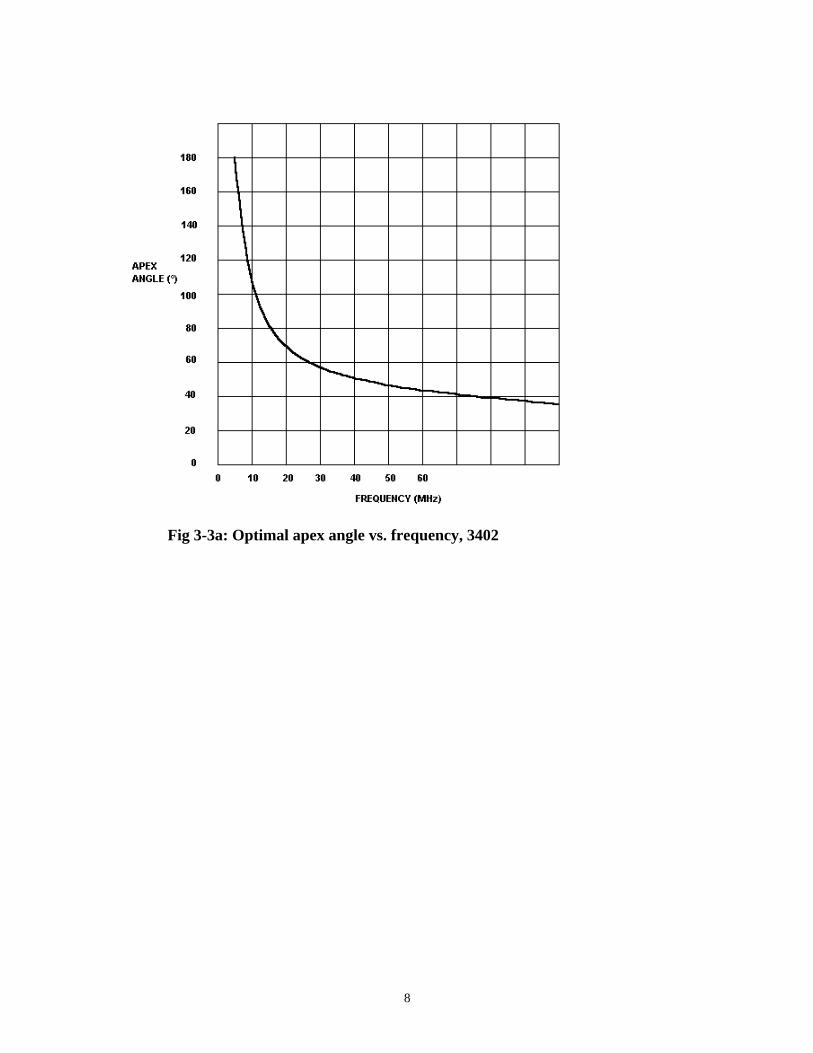
If you choose the vee-beam configuration, you must select an apex angle—theangle between the radiating elements. The apex angle may be optimized for forward gainat a single frequency according to Fig 3-3a for the 3402 and Fig 3-3b for the 3403. Tooptimize gain over a range of frequencies, select a frequency midway between theextremes and use that as your index in the figures.
The footprint, or acreage, needed for any particular vee-beam configuration maybe calculated once the apex angle is known. Refer to Fig 3-4. Dimension A is thedistance between the feed point (mast) and the terminations on an axis at right angles todimension B. Dimension A also depends on the difference in heights of the feed pointand the terminations. Dimension B is the distance between the terminations.
8
Fig 3-3a: Optimal apex angle vs. frequency, 3402

9
Fig 3-3b: Optimal apex angle vs. frequency, 3403
Fig 3-4. Overhead projection showing dimensions A and B of Table 3-2
10
With 100-foot radiating elements, dimension B may be exactly calculated using:B=200sin(θ/2), where θ is the apex angle. Ignoring the difference in heights of the feedpoint and terminations, a minor factor when it is much less than 100 feet, dimension Amay be calculated using: A=100cos(θ/2). Below, Table 3-2 is a table of calculated valuesusing 100-foot radiating elements. For footprint dimensions of the 3403 (50-footelements), divide dimensions by two.
Table 3-2: 3402 antenna footprint dimensionsApex Angle (°) Dimension B (ft) Dimension A (ft)120 173 5090 141 7175 122 7960 100 8745 77 92
The broadside/endfire configuration is obtained by making the apex angle 180°.The antenna then resembles an inverted-vee dipole. If the antenna proves too large forthe available space, it may be shortened as described in subsection C below.
B. Choosing a Grounding Method
The two choices for a grounding method are ground rods or radial counterpoises.When installing the terminations over moist soil, ground rods alone may be sufficient.For rooftop installations or locations with poor soil conductivity, ground radials shouldbe used. In any case, ground radials will improve the performance of the antenna.
Eight-foot copper-clad steel ground rods are available at most hardware stores,along with the proper clamps. Get two of each to hold the ground wires from the twoterminations.
To make ground radials, obtain 200 feet (100 feet for 3403) of 14 AWG, 7/22stranded hard-drawn copper wire (Ten-Tec PN R3300) and at least two copper ovalcrimp sleeves to splice the radials to the ground wires.
C. Changing the Length of the Antenna
The radiating elements may be shortened to accommodate smaller availablespace, but you must shorten them equally to maintain balance. Shortening the elementswill result in reduced efficiency and gain. The elements may be lengthened equally toachieve increased gain and better efficiencies.
Use copper oval crimp sleeves to splice the elements after alteration. Crimpsleeves may be secured by striking them with a hammer to compress them. Be sure tocover the crimps with silicone-rubber adhesive or a similar waterproof material to preventcorrosion.
11
4. Installation
Install the antenna away from other conducting objects. Avoid running theradiating elements in parallel with or close to any large objects, conducting or not.Elevate the terminations as high as possible, using auxiliary masts or supports, ifpossible.
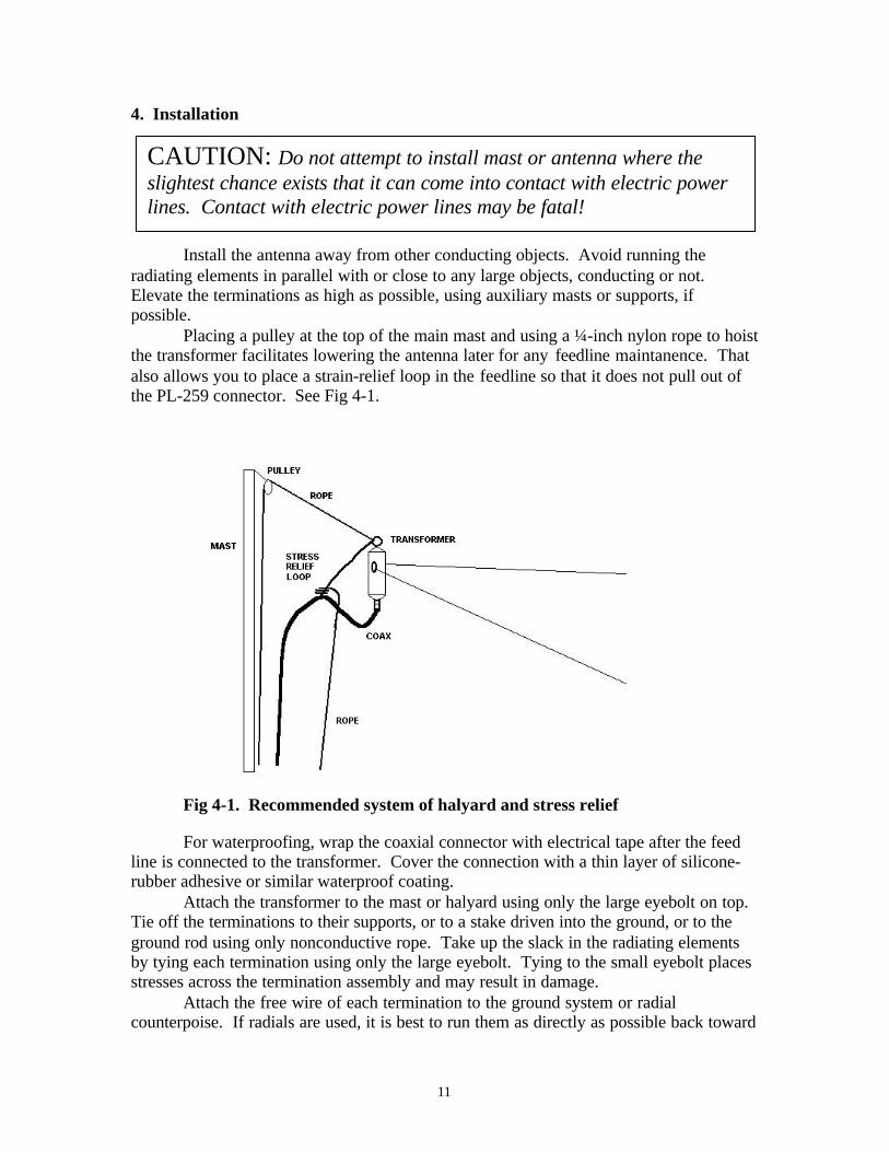
Placing a pulley at the top of the main mast and using a ¼-inch nylon rope to hoistthe transformer facilitates lowering the antenna later for any feedline maintanence. Thatalso allows you to place a strain-relief loop in the feedline so that it does not pull out ofthe PL-259 connector. See Fig 4-1.
Fig 4-1. Recommended system of halyard and stress relief
For waterproofing, wrap the coaxial connector with electrical tape after the feedline is connected to the transformer. Cover the connection with a thin layer of silicone-rubber adhesive or similar waterproof coating.
Attach the transformer to the mast or halyard using only the large eyebolt on top.Tie off the terminations to their supports, or to a stake driven into the ground, or to theground rod using only nonconductive rope. Take up the slack in the radiating elementsby tying each termination using only the large eyebolt. Tying to the small eyebolt placesstresses across the termination assembly and may result in damage.
Attach the free wire of each termination to the ground system or radialcounterpoise. If radials are used, it is best to run them as directly as possible back toward
CAUTION: Do not attempt to install mast or antenna where theslightest chance exists that it can come into contact with electric powerlines. Contact with electric power lines may be fatal!

12
the base of the main mast. Lay them on the ground or bury them about 6 inches deep ifthe land is to be mowed or if there is danger anyone would trip over them or otherwisecome in contact with them.