
Broadband degenerate four-wave-mixing measurements
6
Broadband degenerate four-wave-mixing measurements Stanislav Rozouvan Heidelberg University, Heidelberg, Germany Received August 9, 1999 The nonlinear signal in a degenerate four-wave mixing experiment as a result of diffraction of a spatially dis- tributed third-order nonlinearity is studied theoretically. The approach has been applied for the case of mono- chromatic and ultrashort pulses. As a consequence, the degenerate four-wave mixing signal is found to be in- dependent of light-coherence parameters and cannot be explained as a product of diffraction on a dynamic grating. In this model only the fast component of the signal (the coherent artifact) is related directly to third- order nonlinear processes. The main features (the origins, temporal shapes, dependencies of pump intensity, and modulation effects) of the coherent artifact and a slow-decay component are discussed theoretically and experimentally. © 2000 Optical Society of America [S0740-3224(00)01108-5] OCIS codes: 190.4380, 190.4710. 1. INTRODUCTION Degenerate four-wave mixing (DFWM) interaction from a theoretical point of view is not only a complicated, inter- esting phenomenon in itself (see, for example, Ref. 1), it is also an excellent technique for the determination of x ( 3) tensor numbers. Some features of this tensor can be dis- closed by more detailed numerical simulations of the DFWM processes. Temporal dynamics of the DFWM sig- nal was analyzed by use of a quantum-mechanical ap- proach in most of the theoretical work. The calculations were based mostly on the Bloch equations formalism to solve the kinetic equations for the density matrix (see, for example, Refs. 2 – 4). Such an approach allows us to de- scribe exactly the transient evolution of the coherent re- sponse of two- (or many-level) quantum systems. The phase-matching conditions of DFWM can be explained in this model as a momentum-conservation equation for photons. In the formalism of wave optics, DFWM interaction is considered practically only as diffraction on a dynamic grating (or a few gratings) with parameters that are sup- posed to be dependent on third-order tensor numbers. 5–10 The phase-matching conditions are equivalent in this for- malism to Bragg-diffraction conditions for dynamic grat- ings. The beams in this model are diffracted on two dy- namic gratings for the fast component and only on one for a slow-decay component, and therefore the intensity ratio of the coherent artifact to the slow component should al- ways be 2:1. Attempts to explain some particularities of the DFWM signal shape based on this approach can lead to difficulties. For example, the drastic difference in the decay times of the coherent artifact and the slow-decay component cannot be understood with this formalism. Even the origin of the fast-decay component (the coherent artifact) is sometimes explained as either the loss of phase memory of photocarriers, 11 a pure electronic response, 12 or a coherent nonlinear response. 6 The shape of the DFWM signal was detected to be dependent on pump laser power. 13 The goal in this paper is to obtain a direct solution for the DFWM signal that is proposed to be considered as a diffraction product of induced third-order polarizability and to discuss the features of the signal mainly in respect to the wave-optics theory. From the point of view of the matrix-density formalism we consider a simplified case of very small transverse relaxation times. 2. THEORY A. Coherent Artifact of a Nonlinear Signal in Degenerate Four-Wave Mixing Experiments We apply the wave-optic approach at first to the simpli- fied case of monochromatic waves in order to find common features of DFWM measurements. 1. Monochromatic Interacting Light Waves In the case of DFWM we consider three beams of equal wavelength that interact in a nonlinear media. The fourth signal, the output, is the result produced by these three waves’ nonlinear polarizations. The equation for the nonlinear polarization can be written as P i ~ 3 ! ~ r , t ! 5 x ijkl ~ 3 ! ~ E 1j 1 E 2j 1 E 3j ! 3 ~ E 1k 1 E 2k 1 E 3k !~ E 1l 1 E 2l 1 E 3l ! , (1) where E t , u 5 u E t , u u sin(iv 0 t 1 ik t r) are three interacting fields (the first index, t 5 1...3, denotes the beams, and the second, u 5 1...3, denotes the beams projections on x, y, and z axes), and u k t u 5 2 p / l 0 . Let us consider the case of very small transversal relaxation times in com- parison to the laser-pulse duration (it must be valid for polymers as systems with strongly broadened transi- tions). 1354 J. Opt. Soc. Am. B / Vol. 17, No. 8 / August 2000 Stanislav Rozouvan 0740-3224/2000/081354-06$15.00 © 2000 Optical Society of America
Transcript of Broadband degenerate four-wave-mixing measurements

1354 J. Opt. Soc. Am. B/Vol. 17, No. 8 /August 2000 Stanislav Rozouvan
Broadband degenerate four-wave-mixingmeasurements
Stanislav Rozouvan
Heidelberg University, Heidelberg, Germany
Received August 9, 1999
The nonlinear signal in a degenerate four-wave mixing experiment as a result of diffraction of a spatially dis-tributed third-order nonlinearity is studied theoretically. The approach has been applied for the case of mono-chromatic and ultrashort pulses. As a consequence, the degenerate four-wave mixing signal is found to be in-dependent of light-coherence parameters and cannot be explained as a product of diffraction on a dynamicgrating. In this model only the fast component of the signal (the coherent artifact) is related directly to third-order nonlinear processes. The main features (the origins, temporal shapes, dependencies of pump intensity,and modulation effects) of the coherent artifact and a slow-decay component are discussed theoretically andexperimentally. © 2000 Optical Society of America [S0740-3224(00)01108-5]
OCIS codes: 190.4380, 190.4710.
1. INTRODUCTIONDegenerate four-wave mixing (DFWM) interaction from atheoretical point of view is not only a complicated, inter-esting phenomenon in itself (see, for example, Ref. 1), it isalso an excellent technique for the determination of x (3)
tensor numbers. Some features of this tensor can be dis-closed by more detailed numerical simulations of theDFWM processes. Temporal dynamics of the DFWM sig-nal was analyzed by use of a quantum-mechanical ap-proach in most of the theoretical work. The calculationswere based mostly on the Bloch equations formalism tosolve the kinetic equations for the density matrix (see, forexample, Refs. 2–4). Such an approach allows us to de-scribe exactly the transient evolution of the coherent re-sponse of two- (or many-level) quantum systems. Thephase-matching conditions of DFWM can be explained inthis model as a momentum-conservation equation forphotons.
In the formalism of wave optics, DFWM interaction isconsidered practically only as diffraction on a dynamicgrating (or a few gratings) with parameters that are sup-posed to be dependent on third-order tensor numbers.5–10
The phase-matching conditions are equivalent in this for-malism to Bragg-diffraction conditions for dynamic grat-ings. The beams in this model are diffracted on two dy-namic gratings for the fast component and only on one fora slow-decay component, and therefore the intensity ratioof the coherent artifact to the slow component should al-ways be 2:1. Attempts to explain some particularities ofthe DFWM signal shape based on this approach can leadto difficulties. For example, the drastic difference in thedecay times of the coherent artifact and the slow-decaycomponent cannot be understood with this formalism.Even the origin of the fast-decay component (the coherentartifact) is sometimes explained as either the loss ofphase memory of photocarriers,11 a pure electronicresponse,12 or a coherent nonlinear response.6 The
0740-3224/2000/081354-06$15.00 ©
shape of the DFWM signal was detected to be dependenton pump laser power.13
The goal in this paper is to obtain a direct solution forthe DFWM signal that is proposed to be considered as adiffraction product of induced third-order polarizabilityand to discuss the features of the signal mainly in respectto the wave-optics theory. From the point of view of thematrix-density formalism we consider a simplified case ofvery small transverse relaxation times.
2. THEORYA. Coherent Artifact of a Nonlinear Signal inDegenerate Four-Wave Mixing ExperimentsWe apply the wave-optic approach at first to the simpli-fied case of monochromatic waves in order to find commonfeatures of DFWM measurements.
1. Monochromatic Interacting Light WavesIn the case of DFWM we consider three beams of equalwavelength that interact in a nonlinear media. Thefourth signal, the output, is the result produced by thesethree waves’ nonlinear polarizations. The equation forthe nonlinear polarization can be written as
Pi~3 !~r,t ! 5 x ijkl
~3 ! ~E1j 1 E2j 1 E3j!
3 ~E1k 1 E2k 1 E3k!~E1l 1 E2l 1 E3l!,
(1)
where Et,u 5 uEt,uusin(iv0 t 1 iktr) are three interactingfields (the first index, t 5 1...3, denotes the beams, andthe second, u 5 1...3, denotes the beams projections on x,y, and z axes), and uktu 5 2p/l0 . Let us consider thecase of very small transversal relaxation times in com-parison to the laser-pulse duration (it must be valid forpolymers as systems with strongly broadened transi-tions).
2000 Optical Society of America
Stanislav Rozouvan Vol. 17, No. 8 /August 2000 /J. Opt. Soc. Am. B 1355
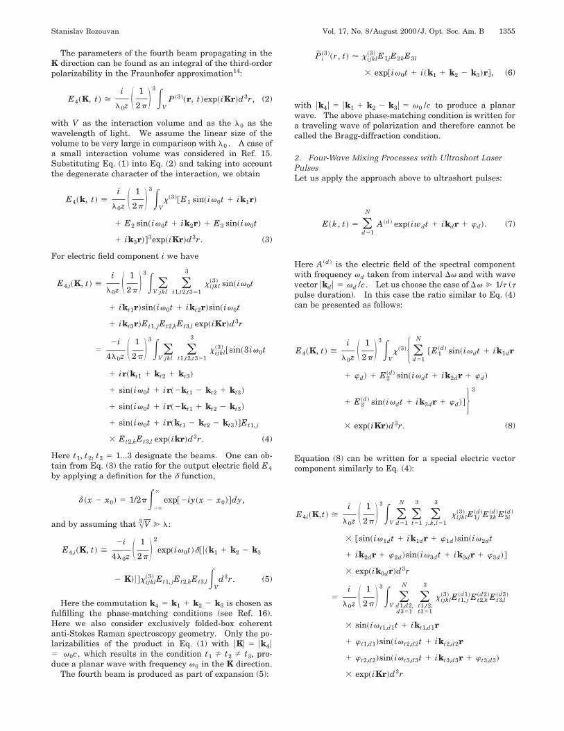
The parameters of the fourth beam propagating in theK direction can be found as an integral of the third-orderpolarizability in the Fraunhofer approximation14:
E4~K, t ! >i
l0z S 1
2pD 3E
VP ~3 !~r, t !exp~iKr!d3r, (2)
with V as the interaction volume and as the l0 as thewavelength of light. We assume the linear size of thevolume to be very large in comparison with l0 . A case ofa small interaction volume was considered in Ref. 15.Substituting Eq. (1) into Eq. (2) and taking into accountthe degenerate character of the interaction, we obtain
E4~k, t ! >i
l0z S 1
2pD 3E
Vx~3 !@E1 sin~iv0t 1 ik1r!
1 E2 sin~iv0t 1 ik2r! 1 E3 sin~iv0t
1 ik3r!#3exp~iKr!d3r. (3)
For electric field component i we have
E4,i~K, t ! >i
l0z S 1
2pD 3E
V(jkl
(t1,t2,t351
3
x ijkl~3 ! sin~iv0t
1 ikt1r!sin~iv0t 1 ikt2r!sin~iv0t
1 ikt3r!Et1, jEt2,kEt3,l exp~iKr!d3r
52i
4l0z S 1
2pD 3E
V(jkl
(t1,t2,t351
3
x ijkl~3 ! @sin~3iv0t
1 ir~kt1 1 kt2 1 kt3!
1 sin~iv0t 1 ir~2kt1 2 kt2 1 kt3!
1 sin~iv0t 1 ir~2kt1 1 kt2 2 kt3!
1 sin~iv0t 1 ir~kt1 2 kt2 2 kt3!#Et1, j
3 Et2,kEt3,l exp~ikr!d3r. (4)
Here t1, t2, t3 5 1...3 designate the beams. One can ob-tain from Eq. (3) the ratio for the output electric field E4by applying a definition for the d function,
d ~x 2 x0! 5 1/2pE2`
`
exp@2iy~x 2 x0!#dy,
and by assuming that A3 V @ l:
E4,i~K, t ! >2i
4l0z S 1
2pD 2
exp~iv0t !d@ u~k1 1 k2 2 k3
2 K!u#x ijkl~3 ! Et1, jEt2,kEt3,lE
Vd3r. (5)
Here the commutation k4 5 k1 1 k2 2 k3 is chosen asfulfilling the phase-matching conditions (see Ref. 16).Here we also consider exclusively folded-box coherentanti-Stokes Raman spectroscopy geometry. Only the po-larizabilities of the product in Eq. (1) with uKu 5 uk4u5 v0c, which results in the condition t1 Þ t2 Þ t3, pro-duce a planar wave with frequency v0 in the K direction.
The fourth beam is produced as part of expansion (5):
Pi~3 !~r, t ! ' x ijkl
~3 ! E1jE2kE3l
3 exp@iv0t 1 i~k1 1 k2 2 k3!r#, (6)
with uk4u 5 uk1 1 k2 2 k3u 5 v0 /c to produce a planarwave. The above phase-matching condition is written fora traveling wave of polarization and therefore cannot becalled the Bragg-diffraction condition.
2. Four-Wave Mixing Processes with Ultrashort LaserPulsesLet us apply the approach above to ultrashort pulses:
E~k, t ! 5 (d51
N
A ~d ! exp~iwdt 1 ikdr 1 wd!. (7)
Here A (d) is the electric field of the spectral componentwith frequency vd taken from interval Dv and with wavevector ukdu 5 vd /c. Let us choose the case of Dv @ 1/t (tpulse duration). In this case the ratio similar to Eq. (4)can be presented as follows:
E4~K, t ! >i
l0z S 1
2pD 3E
Vx~3 !H (
d51
N
@E1~d ! sin~ivdt 1 ik1dr
1 wd! 1 E2~d ! sin~ivdt 1 ik2dr 1 wd!
1 E3~d ! sin~ivdt 1 ik3dr 1 wd!#J 3
3 exp~iKr!d3r. (8)
Equation (8) can be written for a special electric vectorcomponent similarly to Eq. (4):
E4i~K,t ! >i
l0z S 1
2pD 3E
V(d51
N
(t51
3
(j,k,l51
3
x ijkl~3 ! E1j
~d !E2k~d !E3i
~d !
3 @sin~iv1dt 1 ik1dr 1 w1d!sin~iv2dt
1 ik2dr 1 w2d!sin~iv3dt 1 ik3dr 1 w3d!#
3 exp~ik0dr!d3r
5i
l0z S 1
2pD 3E
V(
d1,d2,d351
N
(t1,t2,t351
3
x ijkl~3 ! Et1, j
~d1 !Et2,k~d2 !Et3,l
~d3 !
3 sin~iv t1,d1t 1 ikt1,d1r
1 w t1,d1!sin~iv t2,d2t 1 ikt2,d2r
1 w t2,d2!sin~iv t3,d3t 1 ikt3,d3r 1 w t3,d3!
3 exp~iKr!d3r

1356 J. Opt. Soc. Am. B/Vol. 17, No. 8 /August 2000 Stanislav Rozouvan
52i
4l0z S 12p D 3E
V(
d1,d2,d351
N
(t1,t2,t351
3
x ijkl~3 ! Et1, j
~d1 !Et2,k~d2 !Et3,l
~d3 !
3 $sin@i~v t1,d1 1 v t2,d2 1 v t3,d3!t
1 i~kt1,d1 1 kt2,d2 1 kt3,d3!r 1 w t1,d1
1 w t2,d2 1 w t3,d3# 1 sin@i~2v t1,d1 2 v t2,d2
1 v t3,d3!t 1 i~2kt1,d1 2 kt2,d2 2 kt3,d3!r
2 w t1,d1 2 w t2,d2 1 w t3,d3# 1 sin@i~v t1,d1
2 v t2,d2 2 v t3,d3!t 1 i~kt1,d1 2 kt2,d2
2 kt3,d3!r 1 w t1,d1 2 w t2,d2 2 w t3,d3#
1 sin@i~2v t1,d1 1 v t2,d2 2 v t3,d3!t
1 i~2kt1,d1 1 kt2,d2 2 kt3,d3!r 2 w t1,d1
1 w t2,d2 2 w t3,d3#% 3 exp~iKr!d3r. (9)
It can be shown by applying again the definition of thed function that only these expansion products with (t1Þ t2 Þ t3) can result in a planar wave [vx , ukxu 5 vx /c(c as the velocity of light)]. Let us now show that only themembers of the expansion with equal frequencies (v t1,d15 v t2,d2 5 v t3,d3) and equal wave vectors (ukt1,d1u5 ukt2,d2u 5 ukt3,d3u) can produce a planar wave. Let ustake a member of nonlinear polarizability expansion (9)that produces a planar wave. The phases of the polariz-ability part and the generated planar wave must beequal:
v t1,d1 1 v t2,d2 2 v t3,d3 5 vx ,
H F v t1,d1 /c0
av t1,d1 /cG 1 F2v t2,d2 /c
0av t2,d2 /c
G 2 F 02v t3,d3 /cav t3,d3 /c
G J 1
Aa2 1 1
5 F 0vx /c
avx /cG 1
Aa2 1 1. (10)
Here a is the parameter that determines the angles be-tween the interacting beams, and 1/Aa2 1 1 is the renor-malization coefficient it can easily be shown that equationsystem (10) has only one solution, v t1,d1 5 v t2,d25 v t3,d3 5 v4 . Only the part of the nonlinear polariza-tion induced by a spectral component (d1 5 d2 5 d3condition) results in a planar wave.
Therefore Eqs. (9) can be rewritten as
E4i~k, t ! >i
4l0z S 1
2pD 2
(d51
N
exp~ivdt 1 wd!
3 d ~ uk1,d 1 k2,d 1 k3,d 2 Ku!
3 x ijkl~3 ! Et1 , j
~d ! Et2,k~d ! Et3,l
~d ! EV
d3r. (11)
Let us perform the inverse Fourier transform of ratio(11) by applying the results of Appendix 1. The resultingintensity of the DFWM signal can be presented as a su-perposition of convolution integrals:
E4~t ! ' x~3 !E2`
`
E1~t1 1 t !dt1
3 F E2`
`
E2~t2!E3~t1 1 t2!dt2G5 x~3 !@E1 ^ ~E2 ^ E3!#. (12)
The parameters of the output beams depend on thetemporal shape of the interacting pulses independent oftheir coherent length, 21/Dv. Therefore the signal inDFWM experiments cannot be considered as diffractionon a dynamic grating. It is the product of that part of thethird-order polarizability that presents itself as a travel-ing wave. If the three pump beams are chopped with fre-quencies V1 , V2 , and V3 , respectively, the signal beamwill contain all combinations of the frequencies: V16 V2 6 V3 .
Equation (12) can be useful from a purely practicalpoint of view in order to evaluate a pulse duration in caseusual methods such as two-photon absorption or second-harmonic generation cannot be applied because of techni-cal difficulties (such as weak beam intensity or a UV spec-tral region). For example, for a Gaussian pulse shapethe convolutions’ superposition and the ratio betweenpulse tpulse and signal width tDFWM are
exp~2At2! ^ @exp~2At2! ^ exp~2At2!# ' exp~2At2/3!,
tDFWM 5 tpulseA3. (13)
B. Slow-Decay Component of the Nonlinear Signal inDegenerate Four-Wave Mixing ExperimentsThe slow-decay component (two temporally overlappedpulses, the third delayed in time) can be presented as dif-fraction of the third beam on a dynamic population grat-ing produced by two pump beams. The processes withthe largest available cross sections are responsible for thegrating origin. Usually this is a one-photon absorption(for measurements in the vicinity of a strong absorptionband). Let us consider the interference of two beams inmore detail:
I 5 I1 1 I2 1 2AI1I2 Re@g11~t!#, (14)
where
g11~t! 5^E~t !E* ~t 1 t!&
^uEu2&
is the self-coherence function17 of the light, I1 and I2 arethe intensities of the pump beams, and I is the intensityof the interfering beams that form the dynamic grating(I3 is the intensity of deflecting beam). For the case ofultrashort pulses with a duration much less than thelongtitudial relaxation time the refractive index changesin the population dynamic grating are Im(Dn) 5 Dk ' I.The intensity of the deflected beam is I4 ' I3AI1I2 for thepresent case of equal intensities of the three beams.
The above diffraction consideration in this case has afew important features:

Stanislav Rozouvan Vol. 17, No. 8 /August 2000 /J. Opt. Soc. Am. B 1357
(a) The intensity of the slow component is proportionalto the second power of the applied laser intensity. Thepractical consequence is that the ratio of the coherent ar-tifact to the slow-decay component must depend on the in-teracting pulses intensity.
(b) g11(t) Þ 0 is valid in a general case only for thecoherent-length interval utu , 1/(2Dv). The mutual de-lays between pulses in which the coherent artifact andthe slow-decay component exist are different in general.Practically, this means that the ratio of the coherent ar-tifact to the slow-decay component must depend on mu-tual delays between the pulses (effect noted in Ref. 16).
(c) If the three beams are chopped with frequencies V1 ,V2 , and V3 respectively, the diffracted signal containsthe frequencies (V1 6 V2)/2 6 V3 , V3 6 V1 , andV3 6 V2 and does not contain a V1 6 V2 component as aconsequence of Eqs. (10). This effect has been noted inRef. 16 as well, where the presence (or the absence) of theslow-decay component was dependent on the choppedbeam’s position in respect to the DFWM experiment ge-ometry. These points and the modulation effects de-scribed in Subsection 2.A show a valid, simple, practicalway of disclosing the origin of the output signal duringpump–probe and DFWM experiments.
3. EXPERIMENTIn order to compare the results of theoretical consider-ations given above with actual measurements, we presenthere results of DFWM experiments on polythiophene thinfilms and solutions. The polythiophene derivatives werealready described in Ref. 18. Experiments were per-formed in a folded-box coherent anti-Stokes Raman spec-troscopy geometry with an optical parametrical amplifier,an OPA 9600 (OPA 9800 with an additional set of mir-rors) (Fig. 1). A regenerative Ti:sapphire oscillator (Co-herent REGA 900), with a coupled Kerr-lens mode-lockedTi:sapphire (Coherent Mira 900F) as the source of theseed pulses was used as a pump source. The amplifierproduced 150-fs pulses in the 480–620-nm region (Coher-ent OPA 9600) or the 1.1–1.7-mm region (OPA 9800).The repetition rate was 200 kHz. For improvement ofthe signal-to-noise ratio, a lock-in technique was applied.Two beams were chopped, and the lock-in amplifier oper-ated on the difference frequency. The width of the OPA9800 generated line was 40–70 nm and had a double-peakstructure at the low-energy end of the tuning interval(Fig. 2). The broader laser line, in comparison with thevisible region (OPA9600), is the result of working faraway from the spectral region of strong electron transi-tions and consequently low values of nonlinear disper-sion. The regenerative Ti:sapphire oscillator producedpulses of 180 fs at 797 nm and was used as a laser sourcefor DFWM experiments as well. High light intensity of 5mJ per pulse allowed a very broad dynamic range of themeasurements to be reached.
The set-up contained a l/2 plate that was inserted inone incident beam that permitted measurements with or-thogonal polarizations of the pump beams. This configu-ration was used as a standard check for the absence ofthermal effects during DFWM experiments.
The dependence of the DFWM signal as a function ofpump light intensity is shown in Fig. 3. The measure-ments were performed in a solution of a polythiophene de-rivative from Ref. 18 with a REGA amplifier. The pumplight intensity was tuned by rotation of a l/2 plate beforethe polarizer. A precise stage with a step motor permit-ted an angle accuracy of 2 3 1024 and more than 3 ordersof magnitude dynamic range of the measurements (lim-ited by the burning and the bleaching thresholds for thepolythiophene derivative). The exact crossing position ofthe polarization vectors of the beams and the polarizerwas determined with a sensitive photomultiplier. Theshape of nonlinear response signals corresponding to dif-ferent levels of pump energy (relevant points are markedby arrows) are also presented in Fig. 3. The coherent ar-tifact is practically absent for the case of low pump ener-gies and is dominant for the high-energy region.
This energetic dependence can be interpreted as a sumof two functions: third-order interaction (the coherent
Fig. 1. Experimental setup for DFWM measurements: 1, Ar1
(24-W cw, 514 nm); 2, Ti:sapphire (1-W, 700–950-nm, 90 fs) la-sers; 3, Ti:sapphire oscillator (Coherent REGA 900); 4, near-infrared optical parametrical amplifier (Coherent OPA 9800); 5,l/4 and l/2 plates; 6a, 6b, chopper controller and chopper; 7, lens;8, sample; 9, aperture; 10, Si photodiode; 11, low noise preamp-lifier; 12, lock-in amplifier; 13, PC with IEEE 488 interface card;14, step-motor controller; 15, delay stage.
Fig. 2. Normalized spectra of OPA 9800 lasing lines.

1358 J. Opt. Soc. Am. B/Vol. 17, No. 8 /August 2000 Stanislav Rozouvan
Fig. 3. DFWM signal as a function of the input power density. Shapes of the DFWM signal corresponded to low-power and high-powerpoints (relevant points are marked by arrows).
artifact) with third-power dependence of energy and dif-fraction on the dynamic grating, with presumably second-power dependency from the pump power. The curve hasa lower slope than the expected value of 3, especially atlower pump energies where the processes of diffraction onthe dynamic grating are dominant. Burning and bleach-ing effects are responsible for a sharp signal drop on theupper part of the curve.
The results of DFWM measurements in the near-infrared spectral region on a CS2 sample are shown inFig. 4. The width of the DFWM signal is correlated withthe laser-pulse duration (;250 fs) and not with its coher-ent length (1/Dv ' 60 fs).
4. CONCLUSIONSThe calculation of third-order polarizability spatial distri-butions permits direct solutions to be obtained for thefourth signal in DFWM experiments in a folded-box co-
Fig. 4. DFWM signal from CS2, l 5 1.25 mkm.
herent anti-Stokes Raman spectroscopy geometry as a dif-fraction integral in the Fraunhofer approximation.Characteristic features are as follows:
• Generally, only the coherent-artifact part of the out-put signal is a product of an induced third-order nonlin-earity. The artifact cannot be explained as diffraction onthe induced dynamic grating (or superposition of dynamicgratings).
• The time width of the coherent artifact is indepen-dent of the coherence length of the light and depends onthe time-overlapping integral of the pump pulses.
• The slow-decay component during DFWM experi-ments can be presented as diffraction of the probe beamon a dynamic population grating. The grating param-eters for experiments on p-conjugated polymers are prac-tically independent of third-order nonlinear coefficientsbecause of their comparatively low cross section. The ori-gin of the population grating can be experimentally deter-mined taking into account the particularities found in themodulation technique.
Slow and fast components behave differently as a func-tion of the third power of the pump energy for a coherentartifact and noncubic (presumably quadratic for theabsorption-band spectral region) for the slow-decay com-ponent.
ACKNOWLEDGMENTSI acknowledge with thanks Wolfgang Schrepp (BASF,Germany) for improving the quality of the text and Hel-mut Mohwald (BASF, Germany) and Vladimir Belov (St.Petersburg State University, Russia) for supplying a poly-thiophene derivative. I thank my colleagues Markus

Stanislav Rozouvan Vol. 17, No. 8 /August 2000 /J. Opt. Soc. Am. B 1359
Muller and Kirsten Kuhn from the auxiliary technicalstaff of the BASF for the moral support during my stayingat the BASF.
APPENDIX ALet us consider three functions A(v), B(v), and C(v).The inverse Fourier transform of these functions resultsin a(t), b(t), and c(t) functions:
a~t ! 5 F21(A~v!) 5 E2`
`
A~v!exp~ivt !dv,
b~t ! 5 F21(B~v!) 5 E2`
`
B~v!exp~ivt !dv,
c~t ! 5 F21(C~v!) 5 E2`
`
C~v!exp~ivt !cv. (A1)
It can be shown18 that the inverse Fourier transform ofthe multiplication of two arbitrary functions results in aconvolution integral:
FXE2`
`
a* ~t1!b~t1 1 t2!dt2C5 1/~2p!E
2`
` F E2`
`
a* ~t1!b~t1 1 t2!dt1G3 exp~2ivt2!dt2
5 1/~2p!E2`
`
a* ~t1!
3 F E2`
`
b~t1 1 t2!exp~2ivt2!dt2Gdt1
5 E2`
`
a* ~t1!exp~2ivt1!B~v!dt1 5 2pA~v!B~v!,
F21(A~v!B~v!) 5 2pE2`
`
a* ~t1!b~t1 1 t2!dt1 . (A2)
Let us find the inverse Fourier transform of the multi-plication of three functions. We apply Eqs. (A2) and (A3)twice, performing an inverse Fourier transform on multi-plication of A(v) and the (B(v)C(v)) function and thenon multiplication of B(v) and C(v) functions:
F21(A~v!B~v!C~v!)
5 1/2pE2`
`
a~t 1 t1!dt
3 F E C~v!B~v!exp( 2 ivt1)dv G*5 ~2p!2E
2`
`
a~t 1 t1!dtE2`
`
b~t2!c* ~t1 1 t2!dt2
5 ~2p!2a~t ! ^ (b~t ! ^ c~t !). (A3)
REFERENCES1. R. A. Fisher, ed., Optical Phase Conjugation (Academic,
New York, 1983).2. P. G. R. Smith and P. Ewart, ‘‘Spectral line shape of reso-
nant four-wave mixing induced by broad-bandwidth la-sers,’’ Phys. Rev. A 54, 2347–2355 (1996).
3. M. Kaczmarek, D. R. Meacher, and P. Ewart, ‘‘Time depen-dence of degenerate four-wave mixing with broad band-width pulsed lasers,’’ J. Mod. Opt. 37, 1561–1571 (1990).
4. J. G. Fujimoto and T. K. Yee, ‘‘Diagramatic density matrixtheory of transient four-wave mixing and the measure-ments of transient phenomena,’’ IEEE J. Quantum Elec-tron. QE-22, 1215–1228 (1986).
5. L. Banyai, E. Reitsamer, D. B. Tran Thoai, and H. Hang,‘‘Quantum kinetics of femtosecond four-wave mixing insemiconductors,’’ J. Opt. Soc. Am. B 13, 1278–1283 (1996).
6. J. Oberie, G. Jonusauskas, E. Abraham and C. Rulliere,‘‘Third-order optical nonlinearities of excited states indiphenyl-polyene derivatives: a subpicosecond study,’’Opt. Commun. 124, 616–627 (1996).
7. K. S. Wong, S. G. Han, and Z. V. Vardeny, ‘‘Studies of reso-nant and preresonant femtosecond degenerate four wavemixing in unoriented conducting polymers,’’ J. Appl. Phys.70, 1896–1898 (1991).
8. G. M. Carter, ‘‘Excited-state dynamics and temporally re-solved nonresonant nonlinear optical processes in polydi-acetylenes,’’ J. Opt. Soc. Am. B 4, 1018–1024 (1987).
9. Y. M. Cheung and S. K. Gayen, ‘‘Optical nonlinearities oftea studied by Z-scan and four-wave mixing techniques,’’ J.Opt. Soc. Am. B 11, 636–643 (1994).
10. Y. Pang and P. N. Prasad, ‘‘Photoinduced processes andresonant third-order nonlinearity in poly (3-dodecylthiophene) studies by femtosecond time resolved de-generate four wave mixing,’’ J. Chem. Phys. 93, 2201–2204(1990).
11. K. S. Wong and Z. V. Vardeny, ‘‘Measurements ofx (3)(v,v,2v,v) in conducting polymers at l 5 620 nm,’’Synth. Met. 49, 13–20 (1992).
12. L. Yang, R. Dorsinville, P. P. Ho, W. K. Zou, N. L. Yang,and R. R. Alfano, ‘‘Intensity dependence of picosecond non-linear response time of polydiacetylene,’’ Appl. Phys. Lett.53, 2008–2010 (1988).
13. M. K. Casstevens, M. Samoc, J. Pfleger, and P. N. Prasad,‘‘Dynamics of third-order nonlinear optical processes inLangmuir–Blodgett and evaporated films of phthalocya-nines,’’ J. Chem. Phys. 92, 2019–2024 (1990).
14. H. A. Haus, Waves and Fields in Optoelectronics (Prentice-Hall, Englewood Cliffs, N.J., 1984).
15. S. Rozouvan and W. Schrepp, ‘‘Degenerate four-wave mix-ing measurements on thin polymer films,’’ Appl. Spectrosc.(to be published).
16. S. Rozouvan, ‘‘Commutative spatial and time symmetry ofdegenerate four-wave mixing measurements,’’ J. Opt. Soc.Am. B 16, 768–773 (1999).
17. E. Hecht, Optik (Addison-Wesley, London, 1989).18. R. J. Bell, Introductory Fourier Transform Spectroscopy
(Academic, New York, 1972).


![SECTORIAL FORMS AND DEGENERATE DIFFERENTIAL OPERATORS€¦ · SECTORIAL FORMS AND DEGENERATE DIFFERENTIAL OPERATORS 35 [25]. By our approach we may allow degenerate coefficients](https://static.fdocuments.in/doc/165x107/5e921c5c4d7aaf24746c11ab/sectorial-forms-and-degenerate-differential-operators-sectorial-forms-and-degenerate.jpg)


