Broadband Access Service Attributes and Performance Metrics
51
TECHNICAL REPORT © The Broadband Forum. All rights reserved. TR-304 Broadband Access Service Attributes and Performance Metrics Issue: 1 Issue Date: February 2015
Transcript of Broadband Access Service Attributes and Performance Metrics

TECHNICAL REPORT
© The Broadband Forum. All rights reserved.
TR-304
Broadband Access Service Attributes and Performance Metrics
Issue: 1
Issue Date: February 2015

Broadband Access Service Attributes and Performance Metrics TR-304 Issue 1
February 2015 © The Broadband Forum. All rights reserved 2 of 51
Notice The Broadband Forum is a non-profit corporation organized to create guidelines for broadband network system development and deployment. This Broadband Forum Technical Report has been approved by members of the Forum. This Broadband Forum Technical Report is not binding on the Broadband Forum, any of its members, or any developer or service provider. This Broadband Forum Technical Report is subject to change, but only with approval of members of the Forum. This Technical Report is copyrighted by the Broadband Forum, and all rights are reserved. Portions of this Technical Report may be copyrighted by Broadband Forum members. THIS SPECIFICATION IS BEING OFFERED WITHOUT ANY WARRANTY WHATSOEVER, AND IN PARTICULAR, ANY WARRANTY OF NONINFRINGEMENT IS EXPRESSLY DISCLAIMED. ANY USE OF THIS SPECIFICATION SHALL BE MADE ENTIRELY AT THE IMPLEMENTER'S OWN RISK, AND NEITHER the Forum, NOR ANY OF ITS MEMBERS OR SUBMITTERS, SHALL HAVE ANY LIABILITY WHATSOEVER TO ANY IMPLEMENTER OR THIRD PARTY FOR ANY DAMAGES OF ANY NATURE WHATSOEVER, DIRECTLY OR INDIRECTLY, ARISING FROM THE USE OF THIS SPECIFICATION. Broadband Forum Technical Reports may be copied, downloaded, stored on a server or otherwise re-distributed in their entirety only, and may not be modified without the advance written permission of the Broadband Forum. The text of this notice must be included in all copies of this Broadband Forum Technical Report.

Broadband Access Service Attributes and Performance Metrics TR-304 Issue 1
February 2015 © The Broadband Forum. All rights reserved 3 of 51
Issue History Issue Number Approval Date Publication Date Issue Editor Changes 1 23 February
2015 16 March 2015 Kenneth Ko,
ADTRAN Charles Cook, CenturyLink
Original
Comments or questions about this Broadband Forum Technical Report should be directed to [email protected].
Editor Charles Cook Kenneth Ko
CenturyLink ADTRAN
E2EArchitecture WG Chairs
David Allan David Thorne
Ericsson BT
Vice Chair Sven Ooghe Alcatel-Lucent

Broadband Access Service Attributes and Performance Metrics TR-304 Issue 1
February 2015 © The Broadband Forum. All rights reserved 4 of 51
TABLE OF CONTENTS EXECUTIVE SUMMARY ........................................................................................................... 7
1 PURPOSE AND SCOPE ....................................................................................................... 8
1.1 PURPOSE........................................................................................................................... 8 1.2 SCOPE .............................................................................................................................. 8
2 REFERENCES AND TERMINOLOGY .............................................................................. 9
2.1 CONVENTIONS .................................................................................................................. 9 2.2 REFERENCES ..................................................................................................................... 9 2.3 DEFINITIONS ................................................................................................................... 11 2.4 ABBREVIATIONS ............................................................................................................. 12
3 TECHNICAL REPORT IMPACT ..................................................................................... 14
3.1 ENERGY EFFICIENCY ....................................................................................................... 14 3.2 IPV6 ............................................................................................................................... 14 3.3 SECURITY ....................................................................................................................... 14 3.4 PRIVACY......................................................................................................................... 14
4 INTRODUCTION ............................................................................................................... 15
4.1 USE CASES ..................................................................................................................... 15 4.1.1 Service Provider service monitoring ........................................................................... 16 4.1.2 Subscriber testing ....................................................................................................... 16 4.1.3 Troubleshooting and Diagnostics ............................................................................... 16 4.1.4 3rd party measurements ............................................................................................. 16
4.2 CONCEPTS ...................................................................................................................... 17 4.3 RELATED WORK .............................................................................................................. 19
4.3.1 Broadband Forum documents .................................................................................... 19 4.3.2 Other projects ............................................................................................................ 19
5 PERFORMANCE MEASUREMENT FRAMEWORK .................................................... 20
5.1 FUNCTIONS ..................................................................................................................... 20 5.1.1 Measurement Agent (MA) ........................................................................................... 23 5.1.2 Measurement Peer ..................................................................................................... 25 5.1.3 Measurement Controller ............................................................................................ 25 5.1.4 Data Collector ........................................................................................................... 25 5.1.5 Management Server ................................................................................................... 26
5.2 SUPPRESSION OF MEASUREMENT-RELATED TASKS ............................................................ 26 5.3 MEASUREMENT LOCATIONS ............................................................................................ 28
6 ACCESS SERVICE ATTRIBUTES ................................................................................... 30
6.1 STATIC ACCESS SERVICE ATTRIBUTES ............................................................................. 30 6.2 DYNAMIC ACCESS SERVICE ATTRIBUTES ......................................................................... 32
7 TEST PATH IDENTIFICATION ....................................................................................... 33
8 PERFORMANCE METRICS ............................................................................................. 34
8.1 THROUGHPUT AND RATE ................................................................................................. 34

Broadband Access Service Attributes and Performance Metrics TR-304 Issue 1
February 2015 © The Broadband Forum. All rights reserved 5 of 51
8.2 DELAY ........................................................................................................................... 34 8.3 DELAY VARIATION ......................................................................................................... 35
8.3.1 Packet Delay Variation or Frame Delay Range .......................................................... 35 8.3.2 Inter-Packet and Inter-Frame Delay Variation ........................................................... 36
8.4 LOSS .............................................................................................................................. 36 8.5 CONTINUITY ................................................................................................................... 36 8.6 AVAILABILITY ................................................................................................................ 37 8.7 ROUTE ............................................................................................................................ 37
9 SECURITY .......................................................................................................................... 38
10 PRIVACY ............................................................................................................................ 40
APPENDIX I. USAGE EXAMPLES ....................................................................................... 42
I.1 BROADBAND ACCESS (UNI TO INTERNET DRAIN) ............................................................ 42 I.2 UNI TO INTERMEDIATE POINT (UNI TO CDN, MIDDLE MILE POINT, OTHER …) ................ 43 I.3 HOME NETWORK (UNI TO CE) ........................................................................................ 43 I.4 BUSINESS PREMISES NETWORK ....................................................................................... 43 I.5 UNITP TO EXTERNAL NETWORK .................................................................................... 44 I.6 IDTP TO EXTERNAL NETWORK ....................................................................................... 44 I.7 THIRD PARTY TESTING ................................................................................................... 45
APPENDIX II. POST-PROCESSING OF MEASUREMENT RESULTS .......................... 47
II.1 INTRODUCTION ............................................................................................................... 47 II.2 MINIMIZING AND QUANTIFYING UNCERTAINTY ............................................................... 47
II.2.1 Statistical Metrics ................................................................................................... 47 II.2.2 Derived Measurement Results ................................................................................ 48 II.2.3 Reporting of Test Environment, Conditions, and Parameters .................................. 49
II.3 COMPARING PROVISIONED ACCESS SERVICE ATTRIBUTES WITH MEASUREMENT RESULTS 49 II.4 COMPARING MEASUREMENT RESULTS WITH OTHER MEASUREMENT RESULTS ................. 50
List of Figures Figure 1 – Example Use Case with all Functional Modules............................................................ 22 Figure 2 – Measurement reference points ...................................................................................... 28 Figure 3 – UNITP to IDTP, use case 1 ........................................................................................... 42 Figure 4 – UNITP to IDTP, use case 2 ........................................................................................... 43 Figure 5 – Home network use case ................................................................................................ 43 Figure 6 – External network use case 1 .......................................................................................... 44 Figure 7 – External network use case 2 .......................................................................................... 44 Figure 8 – External network use case 3 .......................................................................................... 45 Figure 9 – Third party testing, use case 1 ....................................................................................... 45 Figure 10 – Third party testing, use case 2 ..................................................................................... 46 Figure 11 – Deriving Single Segment Performance from End-to-end Path Performance................. 48 List of Tables Table 1 – Measurement reference point codes................................................................................ 28

Broadband Access Service Attributes and Performance Metrics TR-304 Issue 1
February 2015 © The Broadband Forum. All rights reserved 6 of 51
Table 2 – Static Access Service Attributes ..................................................................................... 30 Table 3 – TR-181 data model interface object names ..................................................................... 30 Table 4 – Static Access Service Attributes per protocol layer ......................................................... 31 Table 5 – Dynamic Access Service Attributes................................................................................ 32 Table 6 – Test path identifiers........................................................................................................ 33 Table 7 – Customer premises network attributes ............................................................................ 33 Table 8 – Throughput and Rate Metrics ......................................................................................... 34 Table 9 – Delay Metrics ................................................................................................................ 35 Table 10 – Packet delay variation and frame delay range metrics ................................................... 36 Table 11 – Inter-packet and inter-frame delay variation metrics ..................................................... 36 Table 12 – Loss metrics ................................................................................................................. 36 Table 13 – Continuity metrics ........................................................................................................ 37 Table 14 – Availability metrics ...................................................................................................... 37

Broadband Access Service Attributes and Performance Metrics TR-304 Issue 1
February 2015 © The Broadband Forum. All rights reserved 7 of 51
Executive Summary TR-304 specifies a Performance Measurement Framework for measuring performance at or between various points within a network. The network may be contained in a single Service Provider domain or span multiple Service Provider domains. Requirements are provided for the functions, protocols and data structures that may be used by the Performance Measurement Framework. TR-304 also specifies Access Service Attributes and Performance Metrics that can be used in defining measurements and measurement results. Access Service Attributes describe the characteristics of an access service, while Performance Metrics provide the basis for measuring the performance of a network segment or service. The Technical Report lists the attributes applicable to access services and also provides an overview of Performance Metrics.

Broadband Access Service Attributes and Performance Metrics TR-304 Issue 1
February 2015 © The Broadband Forum. All rights reserved 8 of 51
1 Purpose and Scope
1.1 Purpose
Service Providers currently operate a data collection infrastructure for their own purposes such as obtaining network performance data or supporting customers. Regulatory bodies are starting to specify tests in order to obtain results for policy and consumer information purposes. Customers have an interest in quantifying the actual performance of their subscribed-to service. Third-party organizations (commercial and academic) also have an interest in this topic. However there is currently no agreed, widely used test methodology or terminology; this makes meaningful comparison of test data difficult. The goals of this document are therefore to:
a Define a standard set of Access Service Attributes that Service Providers may use to characterize their service offerings. These may be used in their own right and/or to determine the impact on customer experience.
b Define a common framework for accurate measurement of Performance Metrics, including measurement points and measurement methods.
c Enable interoperability between framework functions, including operation across different Service Provider domains.
d Enable interoperability between framework functions from multiple vendors.
1.2 Scope
The scope of this document covers access services. The following are addressed:
1. Specification of the overall Performance Measurement Framework. 2. A set of definitions to enable standard performance testing and reporting. 3. Requirements for the functions comprising the Performance Measurement Framework. 4. Support for tests that span multiple operator networks. 5. Information regarding the quantification and comparison of access services. 6. A common definition and naming of Access Service Attributes.

Broadband Access Service Attributes and Performance Metrics TR-304 Issue 1
February 2015 © The Broadband Forum. All rights reserved 9 of 51
2 References and Terminology
2.1 Conventions
In this Technical Report, several words are used to signify the requirements of the specification. These words are always capitalized. More information can be found be in RFC 2119 [8].
MUST This word, or the term “REQUIRED”, means that the definition is an absolute requirement of the specification.
MUST NOT This phrase means that the definition is an absolute prohibition of the specification.
SHOULD This word, or the term “RECOMMENDED”, means that there could exist valid reasons in particular circumstances to ignore this item, but the full implications need to be understood and carefully weighed before choosing a different course.
SHOULD NOT This phrase, or the phrase "NOT RECOMMENDED" means that there could exist valid reasons in particular circumstances when the particular behavior is acceptable or even useful, but the full implications need to be understood and the case carefully weighed before implementing any behavior described with this label.
MAY This word, or the term “OPTIONAL”, means that this item is one of an allowed set of alternatives. An implementation that does not include this option MUST be prepared to inter-operate with another implementation that does include the option.
2.2 References
The following references are of relevance to this Technical Report. At the time of the publication, the editions indicated were valid. All references are subject to revision; users of this Technical Report are therefore encouraged to investigate the possibility of applying the most recent edition of the references listed below. A list of currently valid Broadband Forum Technical Reports is published at www.broadband-forum.org.
Document Title Source Year [1] TR-069
Amd. 5 CPE WAN Management Protocol BBF 2013
[2] TR-143 Enabling Network Throughput Performance Tests and Statistical Monitoring
BBF 2008
[3] TR-144 Broadband Multi-Service Architecture & Framework BBF 2007

Broadband Access Service Attributes and Performance Metrics TR-304 Issue 1
February 2015 © The Broadband Forum. All rights reserved 10 of 51
Requirements [4] TR-145 Multi-service Broadband Network Functional Modules and
Architecture BBF 2012
[5] TR-178 Multi-service Broadband Network Architecture and Nodal Requirements
BBF 2014
[6] TR-181 Issue 2 Amd 9
Device Data Model for TR-069 BBF 2014
[7] 1905.1a Convergent Digital Home Network for Heterogeneous Technologies Amendment 1: Support of new MAC/PHYs and enhancements
IEEE 2014
[8] RFC 2119 Key words for use in RFCs to Indicate Requirement Levels IETF 1997
[9] RFC 2330 Framework for IP Performance metrics IETF 1998 [10] RFC 2679 A One-Way Delay Metric for IPPM IETF 1999
[11] RFC 2680 A One-Way Packet Loss Metric for IPPM IETF 1999 [12] RFC 2681 A Round Trip Delay Metric for IPPM IETF 1999
[13] RFC 3148 A Framework for Defining Empirical Bulk Transfer Capacity Metrics
IETF 2001
[14] RFC 3393 IP Packet Delay Variation Metric for IP Performance Metrics (IPPM)
IETF 2002
[15] RFC 4656 A One-Way Active Measurement Protocol (OWAMP) IETF 2006 [16] RFC 5357 A Two-Way Active Measurement Protocol (TWAMP) IETF 2008
[17] RFC 5881 Bidirectional Forwarding Detection (BFD) for IPv4 and IPv6 (Single Hop)
IETF 2010
[18] RFC 6349 Framework for TCP Throughput Testing IETF 2011 [19] RFC 6428 Proactive Connectivity Verification, Continuity Check, and
Remote Defect Indication for the MPLS Transport Profile IETF 2011
[20] RFC 6673 Round Trip Packet Loss Metrics IETF 2012
[21] ippm-lmap-path
A Reference Path and Measurement Points for LMAP (draft-ietf-ippm-lmap-path)
IETF
[22] ippm-registry
Registry for Performance Metrics (draft-ietf-ippm-metric-registry)
IETF
[23] lmap-framework
A framework for large-scale measurement platforms (LMAP) (draft-ietf-lmap-framework)
IETF
[24] lmap-information
Information Model for Large-Scale Measurement Platforms (LMAP)
IETF

Broadband Access Service Attributes and Performance Metrics TR-304 Issue 1
February 2015 © The Broadband Forum. All rights reserved 11 of 51
-model (draft-ietf-lmap-information-model) [25] lmap-use-
cases Large-Scale Broadband Measurement Use Cases (draft-ietf-lmap-use-cases)
IETF
[26] G.997.1 Physical layer management for digital subscriber line transceivers
ITU-T 2012
[27] Y.1540 Internet protocol data communication service – IP packet transfer and availability performance parameters
ITU-T 2011
[28] Y.1563 Ethernet frame transfer and availability performance ITU-T 2009
[29] MEF 10.2 Ethernet Service Attributes Phase 2 MEF 2009 [30] MEF10.2.1 Performance Attributes Amendment to MEF 10.2 MEF 2011
[31] A Report on Consumer Wireline Broadband Performance in the U.S.
FCC 2013
2.3 Definitions
The following terminology is used throughout this Technical Report. Access Service Attribute A parameter that describes a characteristic of a service.
Data Collector A function that receives Measurement Results reported by a Measurement Agent.
Ethernet Frame (Frame) An Ethernet Frame (or Frame) is a formatted group of octets sent using Ethernet. Metrics based on Ethernet Frames are measured at the Link layer (Layer 2).
Functional Module From TR-145 [4]: A set of functions, which can be instantiated in a network node. A network node can contain one or more functional modules. A functional module cannot be split between network nodes. Nodal distribution of functional modules is left to TR-178 [5].
Instruction The configuration information provided by a Measurement Controller to a Measurement Agent. An Instruction can contain configuration for tasks, schedules and reporting.
Management Server A function that pre-configures a Measurement Agent.
Measurement Agent (MA)
A function that performs Measurement Tasks under the direction of a Measurement Controller.
Measurement Controller A function that configures a Measurement Agent.
Measurement Method A process for measuring the value of a Performance Metric. Where the process involves multiple MAs, each may perform a different role as specified by the Measurement Method.

Broadband Access Service Attributes and Performance Metrics TR-304 Issue 1
February 2015 © The Broadband Forum. All rights reserved 12 of 51
Measurement Peer A function that may participate in Measurement Tasks with one or more Measurement Agents. A Measurement Peer does not communicate with a Measurement Controller or a Data Collector.
Measurement Result A value resulting from the execution of a Measurement Task.
Measurement Schedule A set of Measurement Task configurations and the times at which they should be performed. The Measurement Schedule is configured in an MA.
Measurement Task The action performed by a single MA in the determination of the value of a Performance Metric executed at a defined time and with defined parameter values.
Network node From TR-145: A physical, self-contained element of a broadband network.
Examples: a DSLAM, an aggregation switch, etc.
Performance Measurement Framework
Definition of the architecture, functions, and how the functions interwork, to enable performance measurements using standards-based mechanisms.
Performance Metric From the LMAP framework [23]: The quantity related to the performance of the network that we’d like to know the value of.
Report The set of Measurement Results and associated information that is sent by an MA to a Data Collector.
Reference Point From TR-145: A reference point is a ‘place’ inside an architecture, where one or more logical, physical, or business interfaces can be instantiated. A reference point can be internal or can be located at a given physical interface
Report Channel The address and security information configured in an MA to communicate with a Data Collector
Service Provider An operator of a data network. This includes providers of Internet service to consumers or businesses, Internet transit services, Content Delivery Networks (CDN), Internet-based applications, as well as enterprise networks.
Suppression An element in the Instruction that temporarily prevents scheduled measurement-related tasks from being initiated and that may or may not stop currently executing Tasks.
2.4 Abbreviations
This Technical Report uses the following abbreviations:
ACS Auto-Configuration Server CPN Customer Premises Network

Broadband Access Service Attributes and Performance Metrics TR-304 Issue 1
February 2015 © The Broadband Forum. All rights reserved 13 of 51
CWMP CPE WAN Management Protocol DDoS Distributed Denial Of Service DSL Digital Subscriber Line DSLAM Digital Subscriber Line Access Multiplexer EMS Element Management System IEEE Institute of Electrical and Electronics Engineers IETF Internet Engineering Task Force IFDV Inter-Frame Delay Variation IP Internet Protocol IPDV Internet Protocol packet Delay Variation IPv4 Internet Protocol version 4 IPv6 Internet Protocol version 6 ITU-T International Telecommunications Union – Telecommunication
Standardization Sector LAN Local Area Network MA Measurement Agent OUI Organizationally Unique Identifier PDV Packet Delay Variation PII Personally Identifiable Information RFC Request For Comments RG Residential Gateway SLA Service Level Agreement SP Service Provider TCP Transmission Control Protocol UDP User Datagram Protocol UNI User to Network Interface

Broadband Access Service Attributes and Performance Metrics TR-304 Issue 1
February 2015 © The Broadband Forum. All rights reserved 14 of 51
3 Technical Report Impact
3.1 Energy Efficiency
The additional energy needed by an existing device or network element to perform occasional measurements is expected to be negligible. Dedicated measurement platforms and devices that perform frequent and bandwidth-intensive or message-intensive measurements will require a measurable amount of energy. If devices are frequently roused from sleep modes in order to perform measurements, this will have a definite impact on energy utilization by those devices. If energy utilization is a concern, it is recommended that the number of devices and network elements engaged in heavy measurement activities be limited to only the quantity needed to achieve a good statistical sampling.
3.2 IPv6
TR-304 IP metrics can be specified, measured and collected over IPv6 as well as IPv4.
3.3 Security
TR-304 introduces a number of security considerations and related requirements. These are discussed in detail in Section 9.
3.4 Privacy
TR-304 introduces a number of privacy considerations and related requirements. These are discussed in detail in Section 10.

Broadband Access Service Attributes and Performance Metrics TR-304 Issue 1
February 2015 © The Broadband Forum. All rights reserved 15 of 51
4 Introduction
There are many types of broadband services, spanning a wide range of different functions and performance capabilities. While this variety is beneficial in that the consumers of these services have a wide range of choices, it can also sometimes be confusing. Even for a single type of service such as Internet access, there are wide variations in marketed speeds, and consumers may not be sure what level of performance they need. In addition, marketing materials from different providers may use generic terms like “speed” in different ways, and other attributes such as usage limits may not be highlighted. As a result, services that seem similar on paper can actually differ significantly in terms of performance or quality of experience. It can also be challenging to verify how a service’s actual performance compares to its specification. For example, the performance may be specified between points at which there is no direct measurement capability, such as from the interface between the customer and the Service Provider’s network to the interface between the Service Provider’s network and the Internet. Assessment of performance may also require multiple measurements made at each of many points in the network. The above issues can make it difficult for potential customers to compare service offerings from different providers, or even in some cases to understand the differences between levels of service offered by the same provider. Further, once a user subscribes to a given service, it can be difficult to interpret the performance delivered by that service. The effects of the issues are not limited to subscribers – Service Providers can also be limited in their ability to measure performance at many different network nodes, or in some cases to troubleshoot and isolate performance issues quickly to a single network connection or node. Regulators may also want to provide information about the performance of Service Providers, or check progress on policy goals for broadband deployment. This document provides a framework that enables a consistent, industry-wide approach to Access Service Attributes definition and performance measurement that can help resolve the issues listed above. It includes:
• An architecture specifying the functional modules (and the requirements on those modules) necessary for scalable, consistent measurement of network and service performance,
• Descriptions of the relevant measurement endpoints, their locations within the network, and requirements for specifying them,
• Description of a set of Access Service Attributes that can be used consistently across different services and networks,
• Descriptions of performance metrics and the related measurement methods needed to enable consistent measurement of service and network performance,
• Informational examples showing how the framework can be used in different parts of the network for different purposes.
Specification of a minimum level of common functionality for Measurement Agents (MAs) should facilitate the broad adoption of MAs allowing network performance to be measured at scale, for example by their incorporation in residential gateways.
4.1 Use Cases

Broadband Access Service Attributes and Performance Metrics TR-304 Issue 1
February 2015 © The Broadband Forum. All rights reserved 16 of 51
The use cases below illustrate how this framework can be of value to different types of users, in particular Service Providers, end users, and third parties.
4.1.1 Service Provider service monitoring
By deploying Measurement Agents within residential gateways and other devices at the network edge as well as at peering points and other key nodes within their networks, Service Providers gain the capability to directly measure the performance of their networks and the performance of the services provided over those networks. A Service Provider having a Measurement Agent on most or all RGs can use sampling to continuously monitor service performance on a statistical basis. SPs can focus on portions of the network that require additional scrutiny based on statistical results without having to deploy additional equipment. The results of such monitoring can be used for various purposes such as scheduling maintenance and network upgrades or to initiate troubleshooting.
4.1.2 Subscriber testing
Service Providers can use the infrastructure defined by this framework to make both Access Service Attribute information and performance measurement capabilities available to their subscribers. Subscribers who have knowledge of their Access Service Attributes are better equipped to understand the capabilities and limitations of the service, and can use that information to determine, for example, what applications they can reasonably run or when it may be time to upgrade. Subscribers who can measure the performance of their services are better equipped to differentiate between performance issues on their Service Providers’ networks and problems due to other factors, either within their own residential networks or due to external causes such as congestion at the far end server. Subscribers may also get valuable insight into the performance of their own residential networks, and how to improve that performance, using tools facilitated by the framework. Service Providers that provide those tools may experience increased customer satisfaction as a result.
4.1.3 Troubleshooting and Diagnostics
When network or service issues do occur, the infrastructure defined by the framework can make troubleshooting easier and faster. Measurement Agents deployed at nodes across the network can allow rapid isolation of a problem to a specific node or connection. This troubleshooting capability can apply in both the Service Provider’s network and within the residential or business customer’s network.
4.1.4 3rd party measurements
The large scale statistical sampling enabled by widespread implementation of this framework is potentially useful to third parties in addition to Service Providers and their customers. Regulators and researchers may see value in the ability to sample performance on a large scale across multiple networks, and to correlate Measurement Results with Access Service Attributes. Third party measurements could use Measurement Agents distributed by the third party in either hardware or software form, or could make use of the test infrastructure deployed by the Service Provider. While

Broadband Access Service Attributes and Performance Metrics TR-304 Issue 1
February 2015 © The Broadband Forum. All rights reserved 17 of 51
the legal, technical and social issues associated with third party testing are outside the scope of this document, we recognize that this use case holds value for a number of interested parties.
4.2 Concepts
TR-304 addresses multiple concepts related to the definition and measurement of broadband performance. The first concept is Access Service Attributes, which define the parameters that describe the characteristics of a service. Access Service Attributes define parameters but do not assign values to them. By assigning values to the Access Service Attributes that apply to a given service and then making those values available (for example, via a web page), a Service Provider can help its subscribers understand the performance expected for the service. Access Service Attributes can also help potential subscribers as well as interested third parties to compare different services. The remaining concepts address the measurement of broadband performance. They are:
• Performance Metrics (with all necessary input parameters) define the key performance characteristics, whose values are determined by measurement. Metrics are supported by the Measurement Methods used by measurement devices. Values resulting from the use of specific Measurement Methods are referred to as Measurement Results. Performance Metrics are defined to support repeatable performance measurement, allowing Measurement Results to be compared across time, between similar services on the same network, and across different networks.
• Measurement Methods define the processes used to determine Measurement Results for
specific Performance Metrics. They may also include a test admission control protocol (such as the control protocols in OWAMP [15] and TWAMP [16]) that can be used to restrict and secure usage of a Measurement Method with a particular MA.
• The Performance Measurement Framework defines and specifies requirements for the
functions in the TR-304 architecture so that they interwork with each other via standards-based mechanisms. The Performance Measurement Framework should enable the widespread implementation and deployment of Measurement Agents (MAs) within service providers’ networks, in subscribers’ premises networks, and at other locations.
Access Service Attributes define the published characteristics of a service, while Performance Metrics describe the observed performance of a service or of a network segment. For example, a given service might have an Access Service Attribute for “Provisioned Maximum Down Capacity.” A service might also specify the maximum latency between two demarcation points. One example of a Performance Metric and associated Measurement Method that may be used to measure a service’s delay performance is specified in RFC2681 [12], which defines a metric for round-trip delay. The functions and interworking processes to support the Measurement Method are defined by the Performance Measurement Framework. Finally, some post-processing of measurement results (briefly discussed in Appendix II) may be performed to generate a set of statistics that characterize the performance of the service relative to “Provisioned Maximum Down Capacity.”

Broadband Access Service Attributes and Performance Metrics TR-304 Issue 1
February 2015 © The Broadband Forum. All rights reserved 18 of 51
Neither Access Service Attributes nor performance measurement is a new concept. The value that this framework adds to those concepts is described below:
• Specification and availability of Access Service Attributes. TR-304 specifies Access Service Attributes that promote clarity in defining services, while allowing for variation in how those services are defined. The specification facilitates the development of applications to make those attributes available to both subscribers and to third parties. This has several benefits:
• Reports have indicated [31] that a high percentage of consumers do not know the speed
of the broadband service to which they have subscribed. Making Access Service Attributes available in a consumer friendly format increases transparency.
• A defined set of Access Service Attributes helps to ensure that third parties such as
regulators or researchers have consistently defined data, facilitating meaningful comparisons of data from different Service Providers.
• A Measurement Agent can compare a subscriber’s current usage to the volume cap for
the service to determine whether or when to initiate previously scheduled tests on that service.
• Interworking between Measurement Agents. Many tests require coordination between the
Measurement Method roles at different points in the network segment under test. This framework specifies the requirements for interworking so that MAs from different vendors and in different networks can identify the tests to be performed including all required parameters such that tests are executed consistently.
• Measurement control and reporting. The Performance Measurement Framework specifies
how Measurement Tasks are controlled and scheduled by a Measurement Controller, how Measurement Results are reported to a Data Collector, and how devices incorporating MAs are managed by a Management Server. It also specifies how management and control of MAs is coordinated, for example when the Management Server and the Measurement Controller are within different administrative domains. This facilitates large scale testing and monitoring within a Service Provider’s network, as well as testing implemented cooperatively between a Service Provider and a third party.
• Security. The Performance Measurement Framework specifies requirements for the security
of the test control, initiation and reporting mechanisms.
• Privacy. The Performance Measurement Framework specifies requirements for the protection of Personally Identifiable Information (PII), as well as for the privacy of user traffic. It also specifies requirements for the protection of Measurement Results and sensitive network data.
An important feature in TR-304 is interworking between MAs Measurement Controllers, and Data Collectors which may be from different vendors and which may or may not be deployed within different networks. The measurement of test segments where the two endpoints lie within different

Broadband Access Service Attributes and Performance Metrics TR-304 Issue 1
February 2015 © The Broadband Forum. All rights reserved 19 of 51
networks is expected to be encountered frequently. One example would be an “end-to-end” measurement that extends from an MA within a subscriber’s premises network to an MA in a remote node which does not lie within the service provider’s network. TR-304 supports both scheduled testing and on-demand testing. Tests can be scheduled in an MA for initiation at specific times or at defined intervals without further intervention from a Measurement Controller, as would be typical in a large scale monitoring or measurement program. In addition, tests can be initiated on demand to facilitate user requests or service troubleshooting.
4.3 Related work
4.3.1 Broadband Forum documents
One of the primary network nodes targeted for the deployment of Measurement Agents is the Customer Premises Equipment (CPE) located at the network edge. These nodes are managed using CPE WAN Management Protocol (CWMP) as defined in TR-069 [1]. CWMP can be used to control the MA, and the Access Service Attributes defined in Section 6 are being added to the device data model for TR-069 specified in TR-181 [6]. TR-143 [2] specifies Measurement Methods to enable network throughput performance tests and statistical monitoring in devices managed via TR-069. These Measurement Methods are noted in Section 8.1 as example methods for measuring various Performance Metrics. The performance management framework defined in TR-304 works within and reuses reference points defined in the broadband access and aggregation network architectures specified in TR-145 [4], TR-178 [5], and the legacy architectures referenced within those documents.
4.3.2 Other projects
The content of this document was developed in close coordination with work conducted in the IETF Large-Scale Measurement of Broadband Performance (LMAP) Working Group. TR-304 and the lmap-framework (A framework for large-scale measurement platforms (LMAP) [23], lmap-use-cases (Large-Scale Broadband Measurement Use Cases) [25], and lmap-information-model (Information Model for Large-Scale Measurement Platforms (LMAP)) [24] are consistent with TR-304, but there are differences in scope. In particular, TR-304 places requirements on the functions in the Performance Measurement Framework, addresses the Management Server, and describes Access Service Attributes. The IETF IP Performance Metrics (IPPM) Working Group has generated many of the Performance Metrics intended to be measured by the Performance Measurement Framework, and they are developing a registry [22] for performance metrics to be used within the framework. In addition, IPPM is developing a reference path [21] for defining measurement points along an end-to-end path.

Broadband Access Service Attributes and Performance Metrics TR-304 Issue 1
February 2015 © The Broadband Forum. All rights reserved 20 of 51
5 Performance Measurement Framework
5.1 Functions
The major functions in the Performance Measurement Framework are:
• Measurement Agent (MA): Performs Measurement Tasks under the direction of a Measurement Controller. The Measurement Agent registers with, and receives Instructions from, a Measurement Controller, performs Measurement Tasks (perhaps in concert with one or more other Measurement Agents and/or Measurement Peers), and reports Measurement Results to one or more Data Collectors.
• Measurement Peer: Performs Measurement Tasks in concert with one or more Measurement
Agents (and perhaps other Measurement Peers). A Measurement Peer does not communicate with a Measurement Controller.
• Measurement Controller: Controls the scheduling and configuration of Measurement Tasks
that are to be done by a Measurement Agent.
• Data Collector: Receives Measurement Results reported by a Measurement Agent.
• Management Server: Manages and configures a physical device or network element. Examples include a TR-069 ACS (Auto-Configuration Server), or an EMS (Element Management System).
The Measurement Agent is the function which performs measurements within the Performance Measurement Framework. MAs can be located throughout the network within residential gateways, routers, and at other nodes. Each MA needs to register with a Measurement Controller. The MA can be configured to do so by its Management Server if it resides within a managed device, or by a factory preset or other means if unmanaged. The Measurement Controller provides the MA with an Instruction, which contains configuration and scheduling information directing the MA to perform one or more Measurement Tasks and to report the Measurement Results to one or more Data Collectors. The Measurement Controller is the function through which measurements are configured and scheduled. A Measurement Controller may provide configuration and scheduling information to tens or hundreds of thousands of MAs, enabling the coordinated implementation of measurement programs that can scale as required by Service Providers. All TR-304 measurements involve at least one MA. Some measurements involve only one MA, for example counting the number of bytes of traffic exiting a particular interface. Other measurements may require two or more MAs to exchange test traffic, with each MA performing a different role as defined by a Measurement Method. Other measurements may require an MA to interact with a node that may not be aware of the Performance Measurement Framework. These nodes, which are not associated with a Measurement Controller and whose capabilities are generally unknown, are
Broadband Access Service Attributes and Performance Metrics TR-304 Issue 1
February 2015 © The Broadband Forum. All rights reserved 21 of 51
referred to as Measurement Peers. For example, an MA may ping a Measurement Peer to determine if a particular address is reachable. Each time an MA participates in a measurement, it is performing a Measurement Task using parameter values configured for that task. Measurement Tasks can be invoked in one of two ways. A MA that initiates a Measurement Task does so according to its schedule. In this case, each additional Measurement Task requires a new scheduled event to invoke it. However, an MA may be involved in a Measurement Task in a responder role, in which case this is invoked by a message received from another MA, without requiring a new scheduled event. Since MAs can be implemented in devices throughout the network, the Performance Measurement Framework enables measurement programs to be implemented at very large scales. A measurement program implemented by a Service Provider might take the following form:
• MAs are implemented in the residential gateways provided to (or acquired by) each subscriber.
• Additional MAs are implemented at points within the access and aggregation networks and at interfaces where traffic is exchanged with other networks.
• Each MA resides within a device managed by a Management Server. Residential gateways
are managed by an ACS via TR-069. Other devices are managed via their respective EMSs. Each device’s Management Server configures the device’s MA to register with the appropriate Measurement Controller.
• Each MA registers with its Measurement Controller. In the process of registering or in subsequent communication, the Measurement Controller may request the MA’s capabilities, which include its Measurement Method roles. The Measurement Controller provides task configuration, scheduling, and reporting information to the MA in the form of an Instruction.
• Each MA uses the provided Instruction to configure and schedule Measurement Tasks and to report the Measurement Results to one or more Data Collectors. For example, the MA within each residential gateway may send a series of packets every hour to a corresponding MA at an inter-network exchange point to test for delay variation and loss.
• Each MA sends its Measurement Results to the appropriate Data Collector(s) according to the schedules and Report Channels defined in the Instruction. By monitoring and analyzing the collected data, the Service Provider can obtain a comprehensive view of network performance including any daily variation.
TR-304 does not limit the operational functions that may coexist in a single device. As one example, a Management Server and a Measurement Controller may coexist in the same device. As another example, two or more Measurement Agents and/or Measurement Peers may coexist in the same device. This is more likely to occur in unmanaged devices such as personal computers, tablets,

Broadband Access Service Attributes and Performance Metrics TR-304 Issue 1
February 2015 © The Broadband Forum. All rights reserved 22 of 51
laptops, and smartphones. Where a Service Provider manages the physical device, it may be operationally simpler to implement all Measurement Method roles within a single MA. It is not necessary for all of these operational functions to be present for every measurement scenario. While a TR-304 scenario will contain at least one Measurement Agent acting under the direction of a Measurement Controller, the MA may be in an unmanaged device, negating the need for a Management Server. A measurement may be performed using one or more Measurement Agents, with or without one or more Measurement Peers. Finally, when a measurement involves two or more MAs, some of the MAs may not send Measurement Results to a Data Collector. Figure 1 shows a use case where all of these functions are present.
Figure 1 – Example Use Case with all Functional Modules
A Measurement Agent is associated with and operates under instructions from a Measurement Controller, and has a set of capabilities known to the Measurement Controller. A Measurement Peer has no such association but may be managed by a means outside the scope of this Technical Report. Further, a Measurement Peer may not be aware that it is participating in measurements initiated by a Measurement Agent. This is the primary difference between the two types of measurement endpoints. Depending on the nature of the Measurement Task being executed, a Measurement Agent may perform the Task on its own or with one or more other Agents or Peers. As long as at least one Measurement Agent is involved, the measurement is in scope for TR-304. Measurement Peer to Measurement Peer measurements are out of scope.
External Network
Customer Premises Network
Access Provider Network
Data Collector
Measurement Controller
RG
MA 1
Measurement function
Network Node
MA 2
Measurement function
ManagementServer
(TR-069 ACS)
Management Server (EMS)Measurement
Controller
Management traffic
External Node
MP
Measurement function
Measurement trafficMeasurement results

Broadband Access Service Attributes and Performance Metrics TR-304 Issue 1
February 2015 © The Broadband Forum. All rights reserved 23 of 51
5.1.1 Measurement Agent (MA)
The MA receives its directions from the Measurement Controller in the form of an Instruction as specified by the LMAP Information Model [24]. The Instruction will contain some or all of the following information:
• Configuration for one or more Measurement Tasks including the Measurement Method role, parameter values, and other information.
• One or more Report Channels defining the address and security information for a Data
Collector to which Measurement Results should be reported.
• Schedules defining when to run Measurement Tasks and when and how to report the results to one or more Data Collectors.
• Suppression information defining measurement-related tasks to be temporarily suppressed
(see Section 5.2). Before it can execute Measurement Tasks, an MA must be associated with a Measurement Controller. An MA may be pre-configured to register with a specific Measurement Controller, or if located within a managed device, it may be configured to do so by a Management Server.
[R-1] An MA MUST be registered with its configured Measurement Controller before undertaking any measurement-related tasks.
[R-2] An MA MUST NOT be registered with more than one Measurement Controller at any given point in time.
[R-3] An MA MUST support disabling all measurement-related tasks in the event that it determines that the Measurement Controller is unreachable.
[R-4] An MA MUST NOT have more than one active Instruction. However, one
Instruction can contain multiple Measurement Task configurations, Measurement Schedules and reporting options.
[R-5] An MA MUST be able to receive a new Instruction from its Measurement Controller.
[R-6] An MA MUST be able to send its active Instruction to its Measurement Controller on demand.
[R-7] An MA MUST be able to receive (from its Measurement Controller) and update any configured aspect of an Instruction.
It is possible for an MA to report data to more than one Data Collector. This will depend on the design and configuration of the MA.

Broadband Access Service Attributes and Performance Metrics TR-304 Issue 1
February 2015 © The Broadband Forum. All rights reserved 24 of 51
[R-8] An MA MUST be able to report Measurement Results to a Data Collector over an associated Report Channel.
[R-9] An MA MUST support Suppression as described in section 5.2.
[R-10] An MA MUST be able to send its supported measurement capabilities to the Measurement Controller.
[R-11] An MA MUST be able to send any measurement task failures and logging
information to its Measurement Controller, in response to a request from its Measurement Controller, and also on its own initiative when triggered by some local event.
Capabilities consist of information that the Measurement Controller needs to know in order to instruct the MA, such as the MA’s supported Measurement Method roles. Failure information covers the MA having been unable to execute a Measurement Task or deliver a Report. Logging information concerns how the MA is operating and may help debugging.
[R-12] The set of measurement capabilities within an MA SHOULD be extensible and capable of being updated.
Since some Measurement Methods have the potential to disrupt network performance or impact user privacy if misused, it is essential that the MA authenticate the Measurement Controller before accepting an Instruction from it. Similarly, since both Access Service Attributes and Measurement Results can contain sensitive information, it is important that the MA provides such information only to an authenticated destination and that it does so over a secure channel.
[R-13] An MA MUST only accept an Instruction from an authenticated Measurement Controller.
[R-14] An MA MUST only send capabilities or Access Service Attributes to an authenticated Measurement Controller .
[R-15] An MA MUST only send Measurement Results or Access Service Attributes to an authenticated Data Collector.
[R-16] An MA MUST use a secure channel that complies with [R-44] through [R-46] for communications with a Measurement Controller and a Data Collector.
[R-17] An MA MUST NOT allow its Control Channel to be reconfigured by an untrusted
source.
An MA may be implemented within a “trusted device” where the MA is a tightly integrated component within the device’s design. An example might be an MA implemented as part of the firmware build for a managed residential gateway. In this case, the device itself may be considered a trusted source and the MA may expose configuration information to the device. In other cases, such as an MA implemented as a software application installed in a laptop,

Broadband Access Service Attributes and Performance Metrics TR-304 Issue 1
February 2015 © The Broadband Forum. All rights reserved 25 of 51
the device is not trusted and the MA must prevent reconfiguration by any source other than its authenticated Measurement Controller.
5.1.2 Measurement Peer
A Measurement Peer is any measurement endpoint participating in a Measurement Task which is not associated with a Measurement Controller. The Measurement Method roles supported by a Measurement Peer may or may not be known to the organization coordinating measurements through the Performance Measurement Framework – how such knowledge is acquired is out of scope. A Measurement Peer may or may not have capabilities specific to Measurement Tasks. An important subclass of Measurement Peers consists of hosts that are unaware of TR-304 but that respond to non-test-specific activity such as pings, DNS queries or http requests. Therefore, this framework does not include requirements for a Measurement Peer. Since the capabilities of a Measurement Peer are not defined, a Measurement Agent performing a measurement with a Measurement Peer should be prepared for unexpected or missing responses.
5.1.3 Measurement Controller
The Measurement Controller is responsible for configuring and scheduling the execution of Measurement Tasks, and the reporting of the associated Measurement Results, in the Measurement Agents under its direction. It does so by sending and updating the Instruction to the devices under its control.
[R-18] A Measurement Controller MUST be able to send and update Instructions to the
MAs under its direction.
[R-19] A Measurement Controller MUST be able to request that any MA under its direction send its capabilities, failure information, logging information, and active Instruction.
[R-20] A Measurement Controller MUST authenticate a Measurement Agent before sending an Instruction to it.
[R-21] A Measurement Controller MUST use a secure channel that complies with [R-44] through [R-46] for communications with an MA.
5.1.4 Data Collector
A Data Collector may receive reports on varying schedules from many different MAs. So long as the Data Collector can authenticate the MA for a given transaction, it will accept the data provided in that transaction. The use of the data after it has been stored in the Data Collector is out of scope for TR-304. However, access to the data is in scope. Since the data may contain sensitive information the Data Collector must prevent access from unauthorized users.

Broadband Access Service Attributes and Performance Metrics TR-304 Issue 1
February 2015 © The Broadband Forum. All rights reserved 26 of 51
[R-22] A Data Collector MUST be able to accept Measurement Results from an Measurement Agent
[R-23] A Data Collector MUST authenticate a Measurement Agent before accepting
Measurement Results from it.
[R-24] A Data Collector MUST use a secure channel that complies with [R-44] through [R-46] for communications with an MA.
[R-25] A Data Collector MUST limit access to stored data to authorized entities.
5.1.5 Management Server
The Management Server has two functions within the scope of TR-304. The first is configuration of the Measurement Agent(s) in managed devices to support the MA’s registration with the desired Measurement Controller. The second function is enabling or disabling the Measurement Agent.
[R-26] The Management Server MUST be able to configure the Measurement Agent so that it registers with the desired Measurement Controller.
[R-27] The Management Server MUST be able to enable and disable the Measurement Agent.
[R-28] The Management Server MUST authenticate the device on which an MA resides before configuring the MA.
[R-29] The Management Server MUST use a secure channel that complies with [R-44] through [R-46] for communications with a managed device on which an MA resides when configuring the MA.
5.2 Suppression of measurement-related tasks
Suppression is the temporary cessation of all or a subset of measurement-related tasks. A Measurement Controller can send a suppress message to the MA that instructs the MA to temporarily suspend some or all of its scheduled measurement-related tasks. Suppression ends either in response to an explicit unsuppress message or at the time indicated in the suppress message. Suppression might be used when the measurement system wants to minimize inessential traffic, for example after a major network incident. Only one suppression message can exist at a time in a given MA. A new suppression message completely replaces the previous one. The set of measurement-related tasks to be suppressed by default is configured in the MA. A suppress message can include options which override the default configurations by explicitly listing the measurement-related tasks and/or schedules to be suppressed. Other options in the suppress message can define the times at which suppression should be started and/or stopped. By default, measurement-related tasks which have already started when suppression begins run to completion, and only those tasks scheduled to start after suppression begins are affected. An option

Broadband Access Service Attributes and Performance Metrics TR-304 Issue 1
February 2015 © The Broadband Forum. All rights reserved 27 of 51
in the suppress message can request that ongoing tasks be halted immediately. However, it may not be practical to do so and an MA is not required to honor the request.
[R-30] A Measurement Controller MUST support sending suppress messages to MAs.
[R-31] An MA MUST support configuring measurement-related tasks to be suppressed or not suppressed by a suppress message which does not specify a set of measurement-related tasks and/or schedules to be suppressed.
[R-32] An MA MUST respond to the default suppress message (i.e., one with no optional
parameters) in the following ways: • The MA MUST NOT start any measurement-related tasks configured to be suppressed
by a default suppress message. • Measurement-related tasks which are configured to not be suppressed by default MUST
NOT be affected. • The MA MUST start suppression immediately. • Suppression MUST continue until the MA receives an unsuppress message.
[R-33] A Measurement Controller MUST be able to specify a set of measurement-related
tasks and/or schedules to be suppressed in the suppress message.
[R-34] If the suppress message includes a list of measurement-related tasks or schedules to be suppressed, the MA MUST suppress only the listed measurement-related tasks or schedules and MUST ignore the default behavior configured per [R-31] for suppression of each measurement-related task.
[R-35] If the suppress message includes both a list of measurement-related tasks and
schedules to be suppressed, the MA MUST suppress all measurement-related tasks and schedules listed and MUST ignore the defaults configured for suppression of each measurement-related task
[R-36] If the suppress message includes a start time, the MA MUST start suppression at the
start time defined.
[R-37] If the suppress message includes an end time, the MA MUST stop suppression at the end time defined.
[R-38] If the suppress message requests that the MA stop ongoing tasks, the MA SHOULD
cease a measurement-related tasks that have already begun and that are to be suppressed.
[R-39] If an MA receives a new suppress message while an existing suppress message is in effect, it MUST completely replace the previous suppress conditions with those in the new message.
[R-40] A Measurement Controller MUST support sending unsuppress messages to MAs.

Broadband Access Service Attributes and Performance Metrics TR-304 Issue 1
February 2015 © The Broadband Forum. All rights reserved 28 of 51
[R-41] An MA MUST stop suppression immediately upon receiving an unsuppress message.
5.3 Measurement Locations
Measurement Agents or Measurement Peers are located at nodes within the segment under test. There are two main aspects of location:
1. Topological (i.e., position in the communication path) 2. Geographical
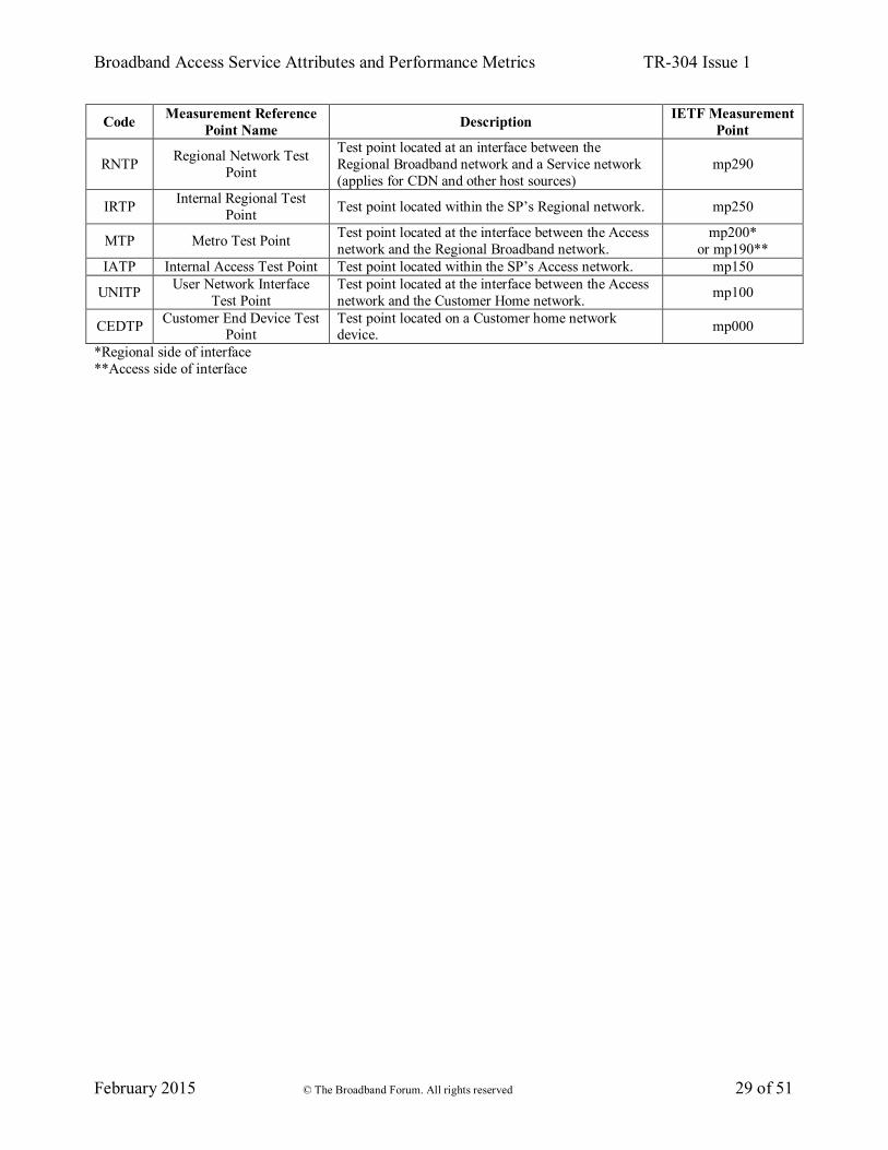
Given the specific relevance of these characteristics and their impact on the meaning of test results, it is necessary to couple the measurement locations and test results. Two types of tests may be conducted: the first involves testing between two or more measurement reference points, and the second is a measurement at a given measurement reference point. Figure 2 identifies the measurement reference points. In some cases (A-10, Va, and T), the measurement reference points correspond to architecture reference points specified by the Broadband Forum in TR-178. In other cases, there are no corresponding Broadband Forum architecture reference points.
Figure 2 – Measurement reference points
Draft-ietf-ippm-lmap-path [21] establishes a similar set of points called measurement points, each identified by a code that contains a number within a range specified by the portion of the network in which the measurement point lies along an end-to-end path. There is a rough correspondence between those measurement points and the measurement reference points identified here. Table 1 identifies the code associated with each measurement reference point, along with a potentially corresponding measurement point from draft-ietf-ippm-lmap-path where applicable. Note that the IETF measurement point numbering can vary based on the network topology and test path.
Table 1 – Measurement reference point codes Code Measurement Reference
Point Name Description IETF Measurement Point
STP Internet Source Test Point Test point located at an Internet Host. mp900 IDTP Internet Drain Test Point Test Point located at the SP interface to the Internet mp290
Internet Source Internet
Service Network /
CDN
Regional Broadband
NetworkAccess Network
Customer Network (LAN)
Customer Equipment
Internet Source
Internet Drain
RegionalNetwork(A-10)
Metro (Va)
User Network Interface
(T)Customer
End DeviceInternal
RegionalInternal Access
Broadband Access Service Attributes and Performance Metrics TR-304 Issue 1
February 2015 © The Broadband Forum. All rights reserved 29 of 51
Code Measurement Reference Point Name Description IETF Measurement
Point
RNTP Regional Network Test Point
Test point located at an interface between the Regional Broadband network and a Service network (applies for CDN and other host sources)
mp290
IRTP Internal Regional Test Point Test point located within the SP’s Regional network. mp250
MTP Metro Test Point Test point located at the interface between the Access network and the Regional Broadband network.
mp200* or mp190**
IATP Internal Access Test Point Test point located within the SP’s Access network. mp150
UNITP User Network Interface Test Point
Test point located at the interface between the Access network and the Customer Home network. mp100
CEDTP Customer End Device Test Point
Test point located on a Customer home network device. mp000
*Regional side of interface **Access side of interface

Broadband Access Service Attributes and Performance Metrics TR-304 Issue 1
February 2015 © The Broadband Forum. All rights reserved 30 of 51
6 Access Service Attributes
Because testing of an end user’s broadband access service is a key use case for this testing framework, it is important that the attributes associated with this access service can be clearly and unambiguously identified for purpose of comparison to performance measures. Access services have three types of attributes, those that must be configured during the setup of the service, those that result from the type of equipment, protocols, and distance involved with providing the service, and those that describe the service as it is sold. Configured attributes such as rate, interface type, and protocol are common to all access services.
6.1 Static Access Service Attributes
A set of static Access Service Attributes is listed in Table 2 and described in the subsections below. Not all services will have values for all of these attributes, and not all Service Providers will make all of the attributes available.
Table 2 – Static Access Service Attributes Attribute Contents Description
Access Service Provider IANA
Enterprise Number <signed integer>
IANA Enterprise Number of the Access Service Provider. IANA numbers listed at http://www.iana.org/assignments/enterprise-numbers.
Access Service Provider name <string>
Name of the Access Service Provider Human readable non-standardized format.
Access Product Name <string>
Identifies the product the customer currently has purchased (unique within Access Service Provider)
Anonymous Service Instance ID <string>
Access network SP Anonymous ID provided for correlation and privacy (unique per access service per customer within an access network SP)
Identifying the protocol associated with a particular rate attribute is important, because this allows for a precise calculation of the contribution of protocol overhead related to such an attribute. Where a device has multiple interfaces, it is also necessary to be certain that the interface stack over which measurements were conducted is the same interface stack to which rate and volume cap attributes apply, prior to comparison with such attributes. In order to have a consistent naming convention for protocols in the context of Access Service Attributes, protocols are identified by using an enumeration of TR-181 [6] interface object names e.g., .Ethernet.Link.{i}. or .IP.Interface.{i}., where {i} is a number assigned by the device and allows multiple interfaces of the same type to be distinguished from one another. At the time of publication, the interface object names supported in the TR-181 data model are shown in Table 3. It is not necessary to use TR-069 or the TR-181 data model in order to make use of the interface naming conventions used in TR-181.
Table 3 – TR-181 data model interface object names Interface object names
.DSL.Line.{i}. .DSL.Channel.{i}.

Broadband Access Service Attributes and Performance Metrics TR-304 Issue 1
February 2015 © The Broadband Forum. All rights reserved 31 of 51
Interface object names .DSL.BondingGroup.{i}. .Optical.Interface.{i}. .Cellular.Interface.{i}. .ATM.Link.{i}. .PTM.Link.{i}. .Ethernet.Interface.{i}. .Ethernet.Link.{i}. .Ethernet.VLANTermination.{i}. .USB.Interface.{i}. .HPNA.Interface.{i}. .MoCA.Interface.{i}. .Ghn.Interface.{i}. .HomePlug.Interface.{i}. .UPA.Interface.{i}. .WiFi.Radio.{i}. .WiFi.SSID.{i}. .ZigBee.Interface.{i}. .Bridging.Bridge.{i}.Port.{i}. .PPP.Interface.{i}. .IP.Interface.{i}. .GRE.Tunnel.{i}.Interface.{i}. .MAP.Domain.{i}.Interface.
The interface objects defined in the TR-181 data model can be identified by object descriptions that include the phrase “a stackable interface object” in the Description field. The attributes in Table 4 are specific to the protocol named as the first attribute in the table. When specifying values for service attributes such as rate or volume caps, these values need to include the payload and header at this protocol level but not the additional headers added at lower protocol levels. Protocol-specific service attributes can be specified for more than one protocol for a service.
Table 4 – Static Access Service Attributes per protocol layer Attribute Units Contents Description
Protocol Enumeration of TR-181 interface objects The protocol layer that the following attributes are for
Provisioned Maximum Down
Rate
Bits per second <integer> Provisioned limit of downstream rate at this protocol
layer
Provisioned Maximum Up Rate
Bits per second <integer> Provisioned limit of upstream rate at this protocol layer
Product Minimum Down Rate
Bits per second <integer>
Per product claim, minimum down rate that the access service can achieve as a general rule at this protocol layer
Product Minimum Up Rate
Bits per second <integer>
Per product claim, minimum up rate that the access service can achieve as a general rule at this protocol layer
Provisioned Maximum Down
Burst
Bits per second <integer> Provisioned burst limit of downstream rate at this
protocol layer
Provisioned Maximum Up Burst
Bits per second <integer> Provisioned burst limit of upstream rate at this protocol
layer
Usage limit type Enumeration of
“Unlimited”, “Capped”, “Metered”
Type of usage limit imposed on the access service at this protocol layer. This parameter may only exist or be populated at one of the protocol layers.
Volume cap MBytes <integer> If “Usage limit” = Capped then volume cap per billing cycle at this protocol layer; otherwise null
Throttled Maximum Down Rate
Bits per second <integer>
If “Usage limit” = Capped and usage is throttled after the cap is exceeded, this represents the limit of downstream rate when the throttle is in place.
Throttled Maximum Up Rate
Bits per second <integer>
If “Usage limit” = Capped and usage is throttled after the cap is exceeded, this represents the limit of upstream rate when the throttle is in place.

Broadband Access Service Attributes and Performance Metrics TR-304 Issue 1
February 2015 © The Broadband Forum. All rights reserved 32 of 51
Attribute Units Contents Description
Lower Layer Protocols
Comma delimited enumeration of TR-181 interface objects
The protocol(s) used below the protocol these attributes are for. Knowledge of the protocol at a layer (and its associated overhead) can be used to derive approximate rate at other layers, if those values are not directly provided.
Access Service Supported Higher-
Layer Protocols
Comma delimited enumeration of TR-181 interface objects
The protocol(s) that may be used above the protocol these attributes are for, but below an IP layer. Knowledge of the protocol at a layer (and its associated overhead) can be used to derive approximate rate at other layers, if those values are not directly provided. As different traffic may make use of different protocol stacks, it is not a given that any particular IP packet will be encapsulated in some or all of these protocols.
6.2 Dynamic Access Service Attributes
The “Usage limit type” attribute in Table 4 identifies the type of usage limit applied to the service. The attribute can have one of three values:
• Unlimited: No usage limit is applied to the service. • Capped: The service is subjected to a volume cap. When this value is used, the “Volume
cap” attribute defines the value of the volume cap which triggers a response from the Service Provider.
• Metered: Usage of the service is metered (e.g., the customer is billed per MByte). When the “Usage limit type” attribute is “capped,” the attributes in Table 5 can be used to determine how close a subscriber’s current usage is to the volume cap. This information can be used, for example, to determine whether or not to perform a scheduled Measurement Task. As these attributes are dynamic, they are only relevant if determined near the time of the test.
Table 5 – Dynamic Access Service Attributes State Units Contents Description
Current usage Mbytes <integer> Usage for this service, that applies towards a usage limit.
Current datetime Datetime The date and time of the Current usage value Retrieved with Current usage as second field

Broadband Access Service Attributes and Performance Metrics TR-304 Issue 1
February 2015 © The Broadband Forum. All rights reserved 33 of 51
7 Test Path Identification
Identifying the end-to-end path of the test is useful for interpreting and comparing test results. Identifiers for the various networks in the test path are shown in Table 6. Note that there may be multiple networks involved in a given test path, and ideally these identifiers would be provided for all of them.
Table 6 – Test path identifiers Identifier Contents Description
Network IANA Enterprise Number <signed integer>
IANA Enterprise Number of the Service Provider(s) whose networks were in the test path. IANA numbers listed at http://www.iana.org/assignments/enterprise-numbers. A -1 value indicates the Customer Premises Network. If it is unknown whether multiple networks were in the path, or if any of the networks are unknown, an entry with -2 shall be present.
Network Name <string>
Name of the Service Provider(s) whose networks were in the path of the test. Human readable non-standardized format. The string “Customer Premises Network” is used to indicate the Customer Premises Network.
Network Role <string>
Comma delimited pair of endpoints of the network segment under test. Endpoints are enumeration of measurement reference point codes from Table 1. Example: “UNITP, CEDTP”
Where one or more of the test path segments is internal to the customer premises network, it may be useful to know the nature of this segment in order to understand whether this segment has a significant impact on a test. This requires that the segment be appropriately characterized. As with all of the other attributes, these attributes may not always be available. This table describes how to represent additional useful information about CPN test path segments if they are known. In addition to knowing the physical networking technology of a CPN test path segment, it would also be useful to know the total amount of traffic transmitted and received on the MA’s network interface, the access device’s CPN interface (facing the MA), and the access device’s access network interface during certain tests, as well as a recent measure of the link capacity between the MA and access device. These measures would all be obtained as the result of specific Measurement Tasks that are included in a Measurement Schedule, or they can be part of a Measurement Method that is defined to include collection of such measures.
Table 7 – Customer premises network attributes Attribute Contents Description
MA network interface PHY
technology
Enumeration of Generic Media Type from IEEE 1905.1a [7], Generic Phy OUI and variant index of organization that defines
the technology
PHY technologies between MA and
access device
Comma delimited list of Generic Phy OUI + Variant Index (IEEE 1905.1a)
enumerations
May be obtained through various topology discovery mechanisms.
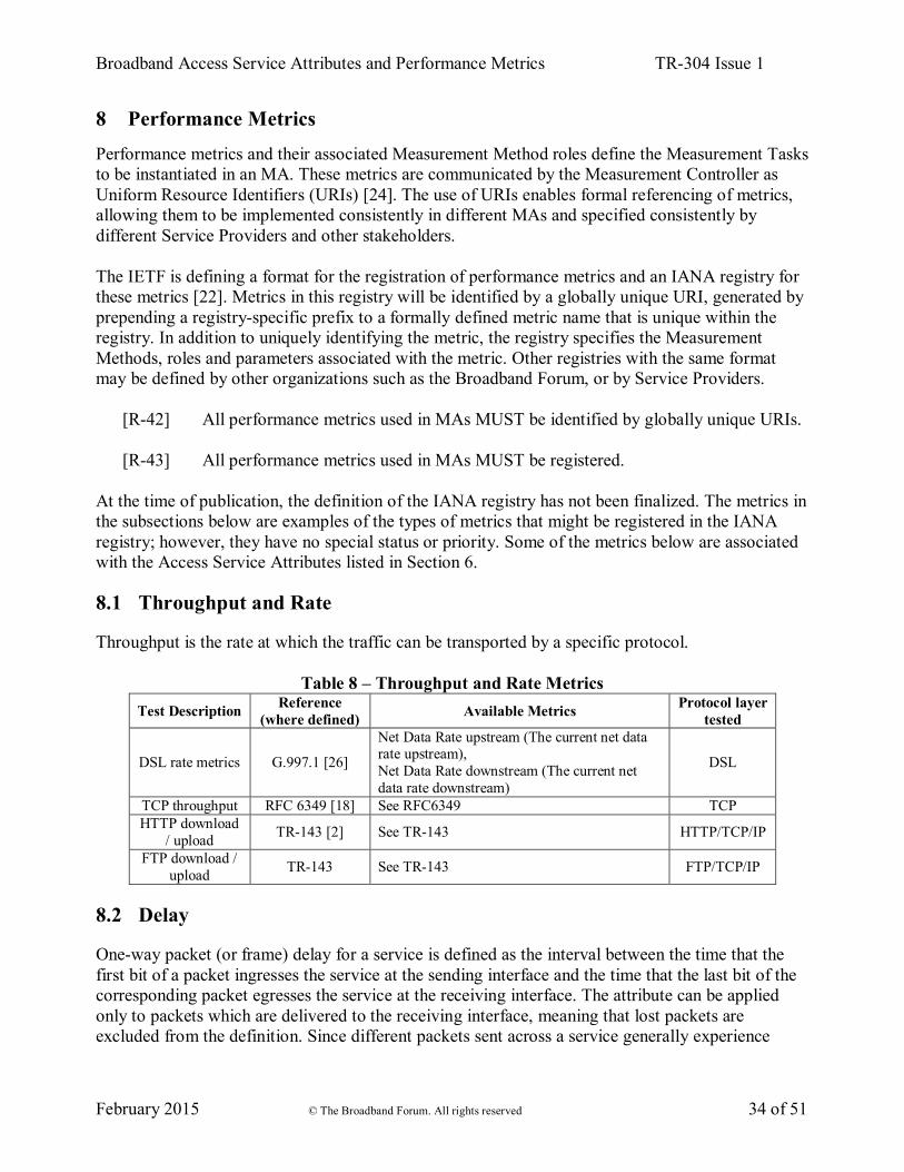
Broadband Access Service Attributes and Performance Metrics TR-304 Issue 1
February 2015 © The Broadband Forum. All rights reserved 34 of 51
8 Performance Metrics
Performance metrics and their associated Measurement Method roles define the Measurement Tasks to be instantiated in an MA. These metrics are communicated by the Measurement Controller as Uniform Resource Identifiers (URIs) [24]. The use of URIs enables formal referencing of metrics, allowing them to be implemented consistently in different MAs and specified consistently by different Service Providers and other stakeholders. The IETF is defining a format for the registration of performance metrics and an IANA registry for these metrics [22]. Metrics in this registry will be identified by a globally unique URI, generated by prepending a registry-specific prefix to a formally defined metric name that is unique within the registry. In addition to uniquely identifying the metric, the registry specifies the Measurement Methods, roles and parameters associated with the metric. Other registries with the same format may be defined by other organizations such as the Broadband Forum, or by Service Providers.
[R-42] All performance metrics used in MAs MUST be identified by globally unique URIs.
[R-43] All performance metrics used in MAs MUST be registered. At the time of publication, the definition of the IANA registry has not been finalized. The metrics in the subsections below are examples of the types of metrics that might be registered in the IANA registry; however, they have no special status or priority. Some of the metrics below are associated with the Access Service Attributes listed in Section 6.
8.1 Throughput and Rate
Throughput is the rate at which the traffic can be transported by a specific protocol.
Table 8 – Throughput and Rate Metrics Test Description Reference
(where defined) Available Metrics Protocol layer tested
DSL rate metrics G.997.1 [26]
Net Data Rate upstream (The current net data rate upstream), Net Data Rate downstream (The current net data rate downstream)
DSL
TCP throughput RFC 6349 [18] See RFC6349 TCP HTTP download
/ upload TR-143 [2] See TR-143 HTTP/TCP/IP
FTP download / upload TR-143 See TR-143 FTP/TCP/IP
8.2 Delay
One-way packet (or frame) delay for a service is defined as the interval between the time that the first bit of a packet ingresses the service at the sending interface and the time that the last bit of the corresponding packet egresses the service at the receiving interface. The attribute can be applied only to packets which are delivered to the receiving interface, meaning that lost packets are excluded from the definition. Since different packets sent across a service generally experience

Broadband Access Service Attributes and Performance Metrics TR-304 Issue 1
February 2015 © The Broadband Forum. All rights reserved 35 of 51
different amounts of delay, the attribute may be specified using a statistical value such as mean packet delay. Since propagation delay is a component of packet delay, the attribute may specify different values for different pairs of sending and receiving interfaces. Some of the Measurement Methods referenced in Table 9 (e.g., OWAMP and TWAMP) include in their definitions a test admission control protocol that can be used to restrict and secure usage of a Measurement Method with a particular MA.
Table 9 – Delay Metrics Test Description Reference
(where defined) Available Metrics Protocol layer tested
Actual Interleaving
Delay G.997.1 Actual Interleaving Delay (Reports the actual
delay of the latency path due to interleaving.) DSL
One-way Frame Delay for a
Service Frame MEF 10.2 [29] One-way Frame Delay Performance; and One-
way Mean Frame Delay Performance. Ethernet
One-way packet delay RFC2679 [10]
Type-P-One-way-Delay-Percentile; Type-P-One-way-Delay-Median; Type-P-One-way-Delay-Minimum; Type-P-One-way-Delay-Inverse-Percentile
IP
Round trip delay RFC 2681 [12]
Type-P-Round-trip-Delay-Percentile; Type-P-Round-trip-Delay-Median; Type-P-Round-trip-Delay-Minimum; Type-P-Round-trip-Delay-Inverse-Percentile
IP
OWAMP RFC4656 [15] One-way packet delay UDP/IP TWAMP RFC5357 [16] Two-way packet delay UDP/IP
UDP Echo Plus TR-143 Determining delay between 2 endpoints. Can also be used to confirm IP connectivity between 2 endpoints.
UDP/IP
8.3 Delay Variation
There are two common methods for measuring delay variation. The first method in Section 8.3.1 measures the delay associated with each packet in a population as a singleton metric, and then uses the sample results for a group of packets to generate statistics. The second method in Section 8.3.2 measures the difference in delays between two packets separated by a defined period as its singleton metric. This method also generates sample and statistical metrics, but the statistics generated by the two types have different uses. The first method generates a delay range that can be correlated, for example, with jitter buffer requirements. The second method can identify step changes in delay that may indicate a change in the path taken by a flow.
8.3.1 Packet Delay Variation or Frame Delay Range
Packet Delay Variation (PDV) or Frame Delay Range (FDR) characterizes the variation in packet (or frame) delay between a sending and a receiving interface. Like delay, PDV/FDR is specified using statistical parameters. The metric is usually specified in terms of the difference between values of delay experienced at two different percentile levels within a population of packets.

Broadband Access Service Attributes and Performance Metrics TR-304 Issue 1
February 2015 © The Broadband Forum. All rights reserved 36 of 51
Table 10 – Packet delay variation and frame delay range metrics Test Description Reference
(where defined) Available Metrics Protocol layer tested
Packet delay variation RFC3393 [14]
Type-P-One-way-ipdv-percentile; Type-P-One-way-ipdv-inverse-percentile; Type-P-One-way-ipdv-jitter; Type-P-One-way-peak-to-peak-ipdv
IP
One-way frame delay range MEF 10.2 One-way Frame Delay Range Performance Ethernet
8.3.2 Inter-Packet and Inter-Frame Delay Variation
Inter-Packet Delay Variation (IPDV) or Inter-Frame Delay Variation (IFDV) is the difference between the one-way delays of a pair of selected packets or frames. It is specified differently than PDV or FDR in that it specifies pairs of packets or frames to compare for each measurement rather than using single delay values for the sample population. The metric is specified using statistical parameters, but each sample within the population is a difference value between two delays rather than a single delay.
Table 11 – Inter-packet and inter-frame delay variation metrics Test Description Reference
(where defined) Available Metrics Protocol layer tested
Inter-packet delay variation RFC3393
Packet delay variation measured using consecutive Type-P packets within the specified interval
IP
Inter-frame delay variation MEF 10.2 Inter-Frame Delay Variation Performance Ethernet
8.4 Loss
The packet (or frame) loss ratio is the ratio of total lost packets (or frames) to total transmitted packets (or frames) in a population of interest.
Table 12 – Loss metrics Test Description Reference
(where defined) Available Metrics Protocol layer tested
One-way IP packet loss RFC2680 [11] Type-P-One-way-Packet-Loss-Average IP
Round trip packet loss RFC6673 [20] Type-P-Round-trip-Loss-<Sample>-Ratio IP
One way frame loss ratio MEF 10.2 One-way Frame Loss Ratio Performance Ethernet
8.5 Continuity
Continuity testing is done to determine whether packets are able to be successfully transported from one test endpoint to another. Unlike loss, it does not attempt to quantify the ratio of lost packets to all packets. When all packets are lost, there is a break in continuity. Where few or no packets are lost, there is no break in continuity.

Broadband Access Service Attributes and Performance Metrics TR-304 Issue 1
February 2015 © The Broadband Forum. All rights reserved 37 of 51
Table 13 – Continuity metrics Test Description Reference
(where defined) Available Metrics Protocol layer tested
Bidirectional Forwarding
Detection (BFD) in MPLS-TP
RFC 6428 [19] Whether or not test messages are successfully received back at the source. MPLS-TP
Bidirectional Forwarding
Detection (BFD) for IPv4 and IPv6 (Single
Hop)
RFC 5881 [17] Whether or not test messages are successfully received back at the source. UDP/IP
UDP Echo Plus TR-143 [2] Whether or not test messages are successfully received back at the source. UDP/IP
8.6 Availability
The percentage of total scheduled service time that is categorized as unavailable based on packet or frame loss. The precise definition of availability may be different for different services. Carrier Ethernet services define the transition between available and unavailable periods using a sliding window mechanism with hysteresis. Recommendation Y.1540 [27] uses a simpler definition based on an IP service unavailability function, which is used to define IP Service Availability and IP Service Unavailability parameters.
Table 14 – Availability metrics Test Description Reference
(where defined) Available Metrics Protocol layer tested
Availability Y.1540 [27] IP service availability IP
Availability MEF 10.2, MEF10.2.1 [30] Availability Performance Ethernet
8.7 Route
Determining the path that packets take when reaching a particular test endpoint can be very important in analyzing tests that run across multiple networks. On an IP network, Traceroute is the best mechanism for identifying all networks and nodes that are traversed. However, since traceroute uses different protocols than other IP tests, it may not be the case that all tests will follow the same path as a traceroute in a multipath network, or even that test traffic will follow the same route as user traffic. Also, there are generally multiple paths that can be taken between two endpoints. In general, tests will run across the same networks, so that there is some value to be gained by multiple traceroute tests that allow a general idea of a test path to be determined.

Broadband Access Service Attributes and Performance Metrics TR-304 Issue 1
February 2015 © The Broadband Forum. All rights reserved 38 of 51
9 Security
Deployment of the performance measurement framework functions in an operator’s network at large scale requires awareness and prevention of multiple types of security threats. Measurement Agents in particular may number in the millions in a large deployment and will commonly be located in unsecured locations within customer premises. Physical layer communications to and from MAs will commonly take place over unsecured channels such as unencrypted wireless LANs. MAs may typically support a wide range of Measurement Methods, including tests that generate a large volume of measurement traffic. Unless appropriate security features are implemented, these factors combine to form a potential vector for large scale amplified DDoS attacks. Other serious potential consequences of inadequate security include the corruption of Measurement Methods or Results and the release of Personally Identifiable Information (PII) to unauthorized parties. The lmap_framework draft [23] discusses a number of security measures required in a large scale measurement program which are also applicable to TR-304. TR-304 covers a number of scenarios which drive additional security considerations. These scenarios (some of which are also covered by lmap) include:
• A single organization (which may be a Service Provider or a third party) manages and operates all MAs, Controllers, Data Collectors and Management Servers.
• A Service Provider manages their MAs through their own Management Server, but allows at least some of the MAs to be controlled by a Measurement Controller operated by a second organization.
• One organization configures a set of MAs to initiate Measurement Tasks which interact with MAs controlled by a second organization. One example of this scenario is a Service Provider initiating tests from within its access network to MAs within a second operator’s network. Another example is a third party initiating tests from within customer premises which interact with MAs in the Service Provider’s network.
• A subscriber installs one or more MAs and performs measurements over the Service Provider’s network.
Requirements related to authentication and secure communications between MA and Measurement Controller and between MA and Data Collector are listed below. A secure channel is defined as pairwise communication between entities that meets the following requirements:
[R-44] A secure channel MUST protect the information communicated against snooping by unauthorized parties.
[R-45] The information communicated via the secure channel MUST be non-repudiable
(e.g. guaranteed to have originated with the sender and be exactly what the sender sent). A secure channel end point can implement additional security safeguards:
[R-46] A secure channel end point SHOULD be able to be configured to rate limit messages received from the peer end point.

Broadband Access Service Attributes and Performance Metrics TR-304 Issue 1
February 2015 © The Broadband Forum. All rights reserved 39 of 51
An MA will commonly be located in a physically accessible device. Additionally, many MAs will be implemented in software that runs in a residential gateway or user device accessible to the subscriber. MA capability may be made available to the subscriber as a software download. Each of these conditions exposes the potential for unauthorized parties to access and modify storage used by the MA. To prevent this, MAs use techniques such as cryptographically signed digests or other equally effective means to prevent undetected tampering.
[R-47] An MA MUST store its configuration data in a way that prevents unauthorized access to or modification of that data.
[R-48] A Measurement Controller MUST store its configuration data in a way that prevents
unauthorized access to or modification of that data.
[R-49] A Management Server MUST store the configuration data for the MAs in devices it manages in a way that prevents unauthorized access to or modification of that data.
[R-50] An MA MUST store Measurement Results in a way that prevents unauthorized
access to or modification of that data.
[R-51] A Data Collector MUST store Measurement Results in a way that prevents unauthorized access to or modification of that data.
Since TR-304 supports deployments involving more than one organization, it becomes important to limit the impact that a security event in one organization can have on another organization’s network. One way to limit that impact is to provide a way for Management Servers to disable MAs that may have been improperly configured. A second way is to limit the addresses to which an MA will respond.
[R-52] If an MA is in a managed device, the MA MUST support being disabled by the device’s Management Server.
[R-53] An MA MUST support filtering of the addresses with which it will participate in
Measurement Tasks.

Broadband Access Service Attributes and Performance Metrics TR-304 Issue 1
February 2015 © The Broadband Forum. All rights reserved 40 of 51
10 Privacy
Both the performance measurement framework and the Access Service Attributes described in this document involve access to information that may have privacy implications. The Performance Measurement Framework enables both measurements that generate test traffic and those that observe user traffic. One potential issue, especially with observation of user traffic, is privacy of user data. Measurements may reveal sensitive information about the end user’s IP address and their usage patterns, for example the times when they use their broadband. Observations of user traffic may also reveal sensitive information, for example the applications they use or the websites they visit. In addition to user information, sensitive data such as network addresses, topology and configurations may be contained in Instructions, MA configurations and Measurement Results. Potential measures to alleviate privacy concerns include excluding sensitive data from reports and not storing such data within the MA longer than required to extract the relevant Measurement Results. The lmap framework draft [23] contains a detailed discussion of privacy considerations, which is recommended reading for individuals specifying, implementing or deploying the functions in the performance management framework. The discussion includes: the entities associated with the performance measurement framework that may have sensitive data; the types of sensitive information that may be measured or stored in a measurement system; the potential privacy issues associated with different types of Measurement Methods; the potential privacy issues associated with communications between different operational functions in the performance measurement framework; how different types of threats may be directed towards a measurement system; and techniques that can be used to mitigate the threats. Several of the mitigation techniques discussed in [23], such as data minimization and aggregation, are implemented by specific measurement or post-processing tasks and are not general performance measurement framework functions. Other techniques, such as anonymity and pseudonymity, are enabled but not mandated by the framework, and depending on the deployment may be recommended as best practices or mandated in certain regulatory environments. The legal regime concerning privacy is country-specific. Anonymization refers to the elimination of information that identifies specific individuals within a set. An example of anonymization would be to use a common group identifier for all Measurement Results associated with the subscribers in the group of interest and to delete or ‘blur’ data such as IP addresses and geographic identifiers that would identify individuals within the group.
[R-54] The Performance Measurement Framework MUST support anonymization of customer-specific data.
Pseudonymity refers to the replacement of Personally Identifiable Information with pseudonyms, such as random equipment identifiers, that do not disclose users’ true identities. Pseudonyms allow Measurement Results from individuals to be tracked over time without identifying those individuals. However, long term use of a pseudonym weakens its ability to mask an individual’s identity.

Broadband Access Service Attributes and Performance Metrics TR-304 Issue 1
February 2015 © The Broadband Forum. All rights reserved 41 of 51
[R-55] The Performance Measurement Framework MUST support pseudonymity of customer-specific data.
A number of mitigation techniques that relate to the communication of, storage of, and access to sensitive data are within the scope of the performance measurement framework functions and protocols These techniques are formalized in requirements for authentication and secure communication in Sections 5 (Performance Measurement Framework) and 9 (Security). The performance measurement framework does not specify where Access Service Attributes are stored or how they are used by a measurement system. In some cases a subset of attributes may be written to devices where the data is then accessible to Measurement Agents; in other cases, all Access Service Attributes will be maintained centrally. In any case, the Access Service Attribute data must be protected from unauthorized access wherever it is communicated, stored or used.
[R-56] The Performance Measurement Framework MUST support the prevention of unauthorized access to Access Service Attribute data.

Broadband Access Service Attributes and Performance Metrics TR-304 Issue 1
February 2015 © The Broadband Forum. All rights reserved 42 of 51
Appendix I. Usage Examples
The Use Cases shown below provide a non-exhaustive set of scenarios illustrating how TR-304 may be implemented and used. I.1 Broadband Access (UNI to Internet drain) Figure 3 shows an example measurement architecture in which the test path is between the broadband access point of demarcation (UNITP) and the point where the access provider network interfaces to external networks (the “Internet drain,” or IDTP). In this example, one measurement agent is installed within a managed residential gateway and the other measurement agent is in a managed network element close to the A10 network interface. The network devices are each managed by their respective EMS elements, which provide their Measurement Agents with the address of the appropriate Measurement Controller. Once the Measurement Agents register with the Measurement Controller, it configures them with additional parameters including the address(es) of the appropriate Data Collector(s). In this scenario, either or both Measurement Agents can have measurements scheduled by the Measurement Controller and either or both Measurement Agents can upload measurement results to the Data Collector(s).
Figure 3 – UNITP to IDTP, use case 1
Figure 4 shows a similar scenario where the IDTP reference point is a Measurement Peer. In this use case, all test scheduling and data collection is coordinated from the Measurement Agent located in the residential gateway. The Measurement Peer responds to Measurement Tasks initiated from other Measurement Agents but initiates no Measurement Tasks on its own.

Broadband Access Service Attributes and Performance Metrics TR-304 Issue 1
February 2015 © The Broadband Forum. All rights reserved 43 of 51
Figure 4 – UNITP to IDTP, use case 2
I.2 UNI to Intermediate Point (UNI to CDN, Middle mile point, other …) The use cases in Figure 3 and Figure 4 are not limited to testing the full path across the access and aggregation networks to the Internet Drain. The second Measurement Agent can be located at other UNITP interfaces such as a CDN interface, or at internal interfaces such as Va. I.3 Home Network (UNI to CE) Figure 5 shows a use case designed to test performance across a customer premises network. In this scenario, a Measurement Agent within a residential gateway performs measurements with a measurement endpoint installed within a laptop or other device within the home network. The second measurement endpoint may be provided as a device feature (e.g., within a set-top box or a wireless access point) or it may be a software application installed on a laptop, tablet or other device. In this use case, the home network measurement endpoint may be either a Measurement Agent or a Measurement Peer.
Figure 5 – Home network use case
I.4 Business Premises Network The Business Premises use case is structurally similar to the home network Use Case described above. In this case there may be multiple Measurement Agents and/or Measurement Peers within the business subscriber’s network performing measurements with an Agent within a business

Broadband Access Service Attributes and Performance Metrics TR-304 Issue 1
February 2015 © The Broadband Forum. All rights reserved 44 of 51
gateway, as well as potentially directly with each other. Data collection may be handled through the business gateway for measurements involving that endpoint, or through other Measurement Agents for direct in-network measurements. I.5 UNITP to External Network In Figure 6, measurements are conducted between the UNITP and a Measurement Agent located outside of the access provider’s network. The external Measurement Agent may be located within another access provider’s network, or it may be at a more central location, including immediately on the other side of the A10 interface. This use case shows an optional path for inter-network coordination, in which the Measurement Controllers in one network learn the capabilities and loading conditions present in external Measurement Agents that are made available to it from an external network. Such an interface is outside the scope of TR-304.
Figure 6 – External network use case 1
A second scenario is shown in Figure 7, in which the external measurement endpoint is a Measurement Peer.
Figure 7 – External network use case 2
I.6 IDTP to External Network

Broadband Access Service Attributes and Performance Metrics TR-304 Issue 1
February 2015 © The Broadband Forum. All rights reserved 45 of 51
By replacing the RG Measurement Agent of Figure 6 with an agent located on the access provider network’s side of A10, the access provider can isolate performance issues between internal and external network segments. This scenario is shown in Figure 8. .
Figure 8 – External network use case 3
I.7 Third Party Testing The Performance Measurement Framework in TR-304 also supports testing performed by third party entities that are not network operators, such as regulators or academic organizations. Such testing may use equipment managed by and with the cooperation of the Access Provider as shown in Figure 9. In this case, the Access Provider is aware of the existence of the test program and has the ability to disable the MAs within its management domain, should a network emergency or a poorly designed test program make that action necessary.
Figure 9 – Third party testing, use case 1
It is also possible for a third party to set up and conduct a testing program in which all measurement endpoints are external to the Access Provider’s network, as well as its management domain. In this case, it is technically possible for the third party to act without the cooperation or even the

Broadband Access Service Attributes and Performance Metrics TR-304 Issue 1
February 2015 © The Broadband Forum. All rights reserved 46 of 51
knowledge of the Access Network provider. Working cooperatively with all network providers potentially affected by large scale testing is strongly recommended, however, both to improve the quality of the testing and to prevent any potential network degradation due to poorly designed tests.
Figure 10 – Third party testing, use case 2

Broadband Access Service Attributes and Performance Metrics TR-304 Issue 1
February 2015 © The Broadband Forum. All rights reserved 47 of 51
Appendix II. Post-processing of Measurement Results
II.1 Introduction Some common issues related to performance measurements can be attributed to incorrect analysis and characterization of the results. This does not mean that the measurement results were inaccurate or imprecise, or that the wrong measurements were performed – merely that the characterization and presentation of the results and the conclusions drawn were in error. This section describes methods for proper analysis and characterization of measurement results. Of particular concern, is analysis or characterization intended to be made public and used as a basis of comparison across Service Providers, or as a determination of whether a Service Provider should be held responsible for any poor performance. II.2 Minimizing and Quantifying Uncertainty According to RFC 2330 [9], “Even the very best measurement methodologies for the very most well behaved metrics will exhibit errors. Those who develop such measurement methodologies, however, should strive to:
• minimize their uncertainties/errors, • understand and document the sources of uncertainty/error, and • quantify the amounts of uncertainty/error.”
Uncertainty is anything that contributes to inaccuracy or imprecision. Uncertainties can be systematic (creating consistent inaccuracy) or random. When measurement results are used to create derived results and draw conclusions, additional uncertainties may exist, which did not necessarily apply to the raw measurement results. These, too, can be systematic or random. The recommendations in the following sections are intended to provide information that will allow uncertainty to be minimized and quantified (to the extent possible). II.2.1 Statistical Metrics Many metrics are statistical in nature. That is, they are calculated from raw measurement results. Examples of such metrics include IP Service Unavailability (percentage of total scheduled service time that is categorized as unavailable based on packet or frame loss), and packet loss ratio (the ratio of total lost packets to total transmitted packets in a population of interest). In order for users of the measurement to consider factors that can impact accuracy and precision, the MA that calculates and reports statistical metrics should report raw measurements (and related information, as described in Section 6) used to calculate the statistical metric. In addition, it is recommended that openly published statistics include an indication as to how the statistics were calculated. This needs to be sufficiently unambiguous so that others can calculate the same statistic, given the same raw measurements.

Broadband Access Service Attributes and Performance Metrics TR-304 Issue 1
February 2015 © The Broadband Forum. All rights reserved 48 of 51
These strategies also allow for independent calculation of standard deviations and other measures of uncertainty. II.2.2 Derived Measurement Results Statistical metrics are a form of derived measurements that can be both precise and accurate, when calculated from precise and accurate raw measurements. There exist, however, other forms of derived measurements that can introduce significant uncertainty. An example of a non-statistical derived measurement that can be inaccurate is shown in Figure 11. This example shows measurements that are taken for an end-to-end path. When the end-to-end measurements are consistent, it is reasonable to assume that the contribution from each individual segment is also consistent. Where the end-to-end path measurements vary, the source of the variation cannot be assumed. Furthermore, taking measurements of the individual segments after an end-to-end path measurement has indicated a problem may not identify which segment caused the variation during the first test, as conditions cannot be assumed to remain the same over time.
Figure 11 – Deriving Single Segment Performance from End-to-end Path Performance
For troubleshooting a problem, it is reasonable to use end-to-end measurements to identify when a problem exists, and individual segment testing to isolate the problem. However, where the measurements may be used to take action against a segment SP or to publicly assign a performance issue to a segment, derived metrics are not recommended. It is recommended that end-to-end path measurements not be attributed to a single segment in the path. Rather, they should be attributed to the end-to-end path, and to all networks in that path. Where derived measurements are openly published, is important that they not be misrepresented as if they were direct or raw measurements. It is important to note that they are derived, and to provide the measurement data used to derive them. It is also recommended that users of such derived measurement results be informed of all factors that can cause the results to be inaccurate and/or imprecise (such as the measurement environment information described in Sections 6.2 through 7). The information that is important will vary, depending on the nature of the derived measurement. For example, when considering the derived measurement of Figure 11, it would be important to let users know:
Other networks
SP network
Home network
TestServer
End-to-end Path
Segment 4 Segment 3 Segment 2 Segment 1

Broadband Access Service Attributes and Performance Metrics TR-304 Issue 1
February 2015 © The Broadband Forum. All rights reserved 49 of 51
• Extra segments were traversed • Known performance of extra segments, and how / when this performance was determined • Whether there are congestion or other traffic management rules in place that would cause
traffic between different endpoints to be treated differently As with statistical measurements, the MA should report all raw measurements (and related information, as described in Section 6) used to calculate any derived metric. II.2.3 Reporting of Test Environment, Conditions, and Parameters It is recommended that raw measurement results be reported with as much information as possible relating to the conditions under which they are conducted. In addition to any applicable and known service and path-related attributes (Section 6), relevant test information that needs to be reported includes:
• Time the measurement was run • Network nodes traversed (including indication of network node operator) • Network links traversed (including indication of network link operator) • Test endpoint information (including equipment or device manufacturer, make, model, etc.) • Unambiguous identification of what measurement test was conducted • Test parameters
Of particular interest when running bandwidth measurement tests is knowing:
• The amount of other traffic going in and out of the same interface the MA is testing across, during the testing
• For access service tests, the amount of traffic going in and out of the WAN access interface during the testing.
It is also recommended that bandwidth tests not be run if there is a significant amount of traffic across the WAN interface immediately prior to starting the bandwidth test. Where the MA is not colocated in the device with the WAN interface, it can be difficult to get information regarding traffic across the WAN interface. Additional mechanisms are needed to enable this but such mechanisms are outside the scope of TR-304. II.3 Comparing Provisioned Access Service Attributes with Measurement
Results Different broadband services often use different physical layer (e.g., DSL, DOCSIS) and link layer (e.g., Ethernet, ATM) technologies that can make it difficult to compare performance across them. For example, due to ATM’s use of 53 byte cells, IP throughput of small IP packets can vary greatly depending on the number of ATM cells the IP packet requires. Another cause of variation is DSL’s sensitivity to loop length (the length of the loop will impact the maximum throughput a customer can achieve). Where the IP packets used for measurement differ from the IP packets normally generated by an end user, IP measurements may not accurately reflect the throughput experienced by the end user.

Broadband Access Service Attributes and Performance Metrics TR-304 Issue 1
February 2015 © The Broadband Forum. All rights reserved 50 of 51
Where Access Service Attributes are provided at a different protocol layer than the one where measurements are made, it is important to know this and to account for differences in protocol overhead prior to doing any comparison. Where a customer’s link is capable of achieving more than the marketed expectation, a provider may choose to provision the link so that the marketed expectation is exceeded under certain conditions. When over-achieving measurements are averaged with under-achieving measurements, they may mask the existence of under-achieving measurements. Where a user’s usage may be throttled after a certain usage threshold is reached, it is important to know this, so that performance is compared correctly to either the pre- or post-throttled allowed bandwidth. Some access services may specify a minimum and maximum bandwidth range, where the actual achieved bandwidth is dependent on loop length or noise. For an individual user, it can be useful to compare their measured bandwidth against the minimum and maximum achievable values. Averaging the measured bandwidth of users who cannot achieve the maximum together with users who can achieve the maximum is not a useful metric, however. It would be more useful to know whether all users can achieve the minimum, and the number of users that fall in various bandwidth ranges across the minimum to maximum spectrum. It would also be useful to know, for those that can achieve the maximum, the average bandwidth over time (to see if and how much it varies during periods of network congestion). II.4 Comparing Measurement Results with Other Measurement Results Caution is advised when comparing measurement results that take different paths, are collected using different tests, have different endpoints, or are collected at different times. Comparisons that involve changing a single variable are valuable and can provide useful information. Examples of such comparisons include
• Comparing results from a particular end user, where test endpoints are the same, tests are the same, and only the time of testing is varied; this provides a good understanding of how that end user’s performance changes over time.
Comparisons where multiple variables have changed may be of limited value, as it may be difficult to identify which variable is responsible for the difference between the measurement results. Examples of such a comparison would be:
• Comparing results from 2 geographically distinct end users who are connected to different providers, using different tests, to different test endpoints; this comparison provides limited useful information.
Comparisons of the difference between Access Service Attribute bandwidths to measured bandwidths of users may be of limited use as they are subject to factors which are beyond the service provider’s control, for example loop length. Some useful comparisons are:

Broadband Access Service Attributes and Performance Metrics TR-304 Issue 1
February 2015 © The Broadband Forum. All rights reserved 51 of 51
• The percentage of time that users’ measured bandwidth was significantly below their maximum measured bandwidth.
• The percentage of users of an access service who are able to attain the maximum Access Service Attribute bandwidth,
• The percentage of users of an access service who are able to attain the minimum Access Service Attribute bandwidth.
• The percentage of time that users of an access service had measured bandwidth below the minimum Access Service Attribute bandwidth.
• The percentage of users of an access service who experience measured bandwidth below minimum Access Service Attribute bandwidth more than some small percentage of the time.
End of Broadband Forum Technical Report TR-304