![Radius Attributes Catalog - Broadband Forum1 18 July 2016 5 August 2016 Frederic Klamm, Orange Original ... [10] TR-242 Issue 1 IPv6 Transition Mechanisms for Broadband Networks BBF](https://static.fdocuments.in/doc/165x107/5ff0445bd3c0e66c3771fc0d/radius-attributes-catalog-broadband-forum-1-18-july-2016-5-august-2016-frederic.jpg)
Broadband Access Service Attributes and Performance Metrics€¦ · Web viewStraw Ballot....
78
Working Text Straw Ballot bbf2012.1190.09 WT-304 Broadband Access Service Attributes and Performance Metrics Revision: 09 Revision Date: July 2014 © The Broadband Forum. All rights reserved.
Transcript of Broadband Access Service Attributes and Performance Metrics€¦ · Web viewStraw Ballot....
Working Text
Straw Ballotbbf2012.1190.09
WT-304Broadband Access Service Attributes and Performance Metrics
Revision: 09Revision Date: July 2014
© The Broadband Forum. All rights reserved.

Broadband Access Service Attributes and Performance Metrics WT-304 Revision 09
July 2014 © The Broadband Forum. All rights reserved
2 of 55
Broadband Access Service Attributes and Performance Metrics WT-304 Revision 09
Notice
The Broadband Forum is a non-profit corporation organized to create guidelines for broadband network system development and deployment. This Broadband Forum Working Text is a draft, and has not been approved by members of the Forum. Even if approved, this Broadband Forum Working Text is not binding on the Broadband Forum, any of its members, or any developer or service provider. This Broadband Forum Working Text is subject to change. This Broadband Forum Working Text is copyrighted by the Broadband Forum, and portions of this Broadband Forum Working Text may be copyrighted by Broadband Forum members. This Working Text is for use by Broadband Forum members only. Advance written permission by the Broadband Forum is required for distribution of this Broadband Forum Working Text in its entirety or in portions outside the Broadband Forum.
Recipients of this document are requested to submit, with their comments, notification of any relevant patent claims or other intellectual property rights of which they may be aware that might be infringed by any implementation of the Specification set forth in this document, and to provide supporting documentation.
THIS SPECIFICATION IS BEING OFFERED WITHOUT ANY WARRANTY WHATSOEVER, AND IN PARTICULAR, ANY WARRANTY OF NONINFRINGEMENT IS EXPRESSLY DISCLAIMED. ANY USE OF THIS SPECIFICATION SHALL BE MADE ENTIRELY AT THE IMPLEMENTER'S OWN RISK, AND NEITHER the Forum, NOR ANY OF ITS MEMBERS ORSUBMITTERS, SHALL HAVE ANY LIABILITY WHATSOEVER TO ANY IMPLEMENTER OR THIRD PARTY FOR ANY DAMAGES OF ANY NATURE WHATSOEVER, DIRECTLY OR INDIRECTLY, ARISING FROM THE USE OF THIS SPECIFICATION.
The text of this notice must be included in all copies of this Broadband Forum Working Text.
July 2014 © The Broadband Forum. All rights reserved
3 of 55
Broadband Access Service Attributes and Performance Metrics WT-304 Revision 09
Revision History
Revision Number
Revision Date Revision Editor
Changes
00 September 2012
Charles Cook, CenturyLinkKenneth Ko, ADTRAN
Initial content from:bbf2012.746.03bbf2012.794.00bbf2012.899.01
01 January 2013 Ken Ko, ADTRAN Added content from bbf2012.441.05 as approved in 4Q12 meeting.
02 March 2013 Charles Cook, CenturyLinkKen Ko, ADTRAN
Added content from bbf2013.248.00 and bbf2013.264.00 as approved in 1Q13 meeting.
03 April 2013 Charles Cook, CenturyLink Added content fromBbf2013.408.00 as approved on April 18, 2013 call.
04 June 2013 Ken Ko, ADTRAN Reorganized document as agreed per bbf2013.645.00.Added introductory text with suggested changes per bbf2013.656.01.Added section 5.2 per bbf2013.638.01.
05 March 2014 Ken Ko, ADTRANCharles Cook, CenturyLink
Concepts from bbf2013.1294.02.Requirements from bbf2013.868.06.Definitions to support Terminology
as agreed in bbf2014.020.01.Updates from bbf2014.012.00.Separated Service Attributes and
Performance Metrics sections and reorganized Performance Measurement Framework section.
MA requirements as agreed in bbf2014.024.02 and bbf2014.256.01.
06 May 2014 Ken Ko, ADTRAN Text agreed from bbf2014.118.02.
07 June 2014 Charles Cook, CenturyLink Text agreed from bbf2014.342.02.
08 June 2014 Ken Ko, ADTRAN Text agreed from: bbf2014.591.00; bbf2014.595.01; bbf2014.398.00; bbf2014.545.00; bbf2014.035.05; bbf2014.550.02.
Other modifications per review in 27 June meeting.
July 2014 © The Broadband Forum. All rights reserved
4 of 55
Broadband Access Service Attributes and Performance Metrics WT-304 Revision 09
09 July 2014 Ken Ko, ADTRAN Text agreed from bbf2014.666.01; agreed changes from 10 July Straw Ballot readiness review.
Comments or questions about this Broadband Forum Working Text should be directed to [email protected].
Editor Charles CookKenneth Ko
CenturyLinkADTRAN
E2EArchitectureWG Chairs
David AllanDavid Thorne
EricssonBT
Vice Chair Sven Ooghe Alcatel-Lucent
July 2014 © The Broadband Forum. All rights reserved
5 of 55

Broadband Access Service Attributes and Performance Metrics WT-304 Revision 09
TABLE OF CONTENTS
EXECUTIVE SUMMARY..................................................................................................................8
1 PURPOSE AND SCOPE...........................................................................................................9
1.1 PURPOSE................................................................................................................................91.2 SCOPE....................................................................................................................................9
2 REFERENCES AND TERMINOLOGY...............................................................................10
2.1 CONVENTIONS.....................................................................................................................102.2 REFERENCES........................................................................................................................102.3 DEFINITIONS........................................................................................................................132.4 ABBREVIATIONS..................................................................................................................18
3 WORKING TEXT IMPACT..................................................................................................21
3.1 ENERGY EFFICIENCY...........................................................................................................213.2 IPV6....................................................................................................................................213.3 SECURITY............................................................................................................................213.4 PRIVACY..............................................................................................................................21
4 INTRODUCTION....................................................................................................................21
4.1 USE CASES..........................................................................................................................224.1.1 Service Provider service monitoring..............................................................................224.1.2 Subscriber testing...........................................................................................................224.1.3 Troubleshooting and Diagnostics...................................................................................234.1.4 3rd party measurements.................................................................................................23
4.2 CONCEPTS...........................................................................................................................234.3 RELATED WORK..................................................................................................................26
4.3.1 Broadband Forum documents........................................................................................264.3.2 Other projects.................................................................................................................26
5 PERFORMANCE MEASUREMENT FRAMEWORK.......................................................26
5.1 FUNCTIONS..........................................................................................................................265.1.1 Measurement Agent (MA)...............................................................................................285.1.2 Measurement Peer..........................................................................................................305.1.3 Measurement Controller................................................................................................305.1.4 Data Collector................................................................................................................315.1.5 Management Server........................................................................................................31
5.2 PROTOCOLS AND DATA STRUCTURES.................................................................................315.2.1 Management Server Protocol and Data Structures.......................................................325.2.2 Measurement Controller Protocol and Data Structure..................................................325.2.3 Suppression of scheduled measurements........................................................................32
5.3 MEASUREMENT ENDPOINTS................................................................................................335.3.1 Location Attribute (Mapping to Broadband Forum reference points)...........................33
6 ACCESS SERVICE ATTRIBUTES.......................................................................................35
6.1 STATIC ACCESS SERVICE ATTRIBUTES...............................................................................356.1.1 Capacity..........................................................................................................................37
July 2014 © The Broadband Forum. All rights reserved
6 of 55
Broadband Access Service Attributes and Performance Metrics WT-304 Revision 09
6.1.2 Usage-based limits.........................................................................................................376.2 DYNAMIC ACCESS SERVICE ATTRIBUTES...........................................................................386.3 CUSTOMER PREMISES NETWORK (CPN) ATTRIBUTES.......................................................386.4 TEST PATH ATTRIBUTES.....................................................................................................39
7 PERFORMANCE METRICS.................................................................................................40
7.1 CAPACITY............................................................................................................................407.2 DELAY.................................................................................................................................417.3 PACKET DELAY VARIATION OR FRAME DELAY RANGE.....................................................427.4 INTER-PACKET AND INTER-FRAME DELAY VARIATION.....................................................427.5 LOSS....................................................................................................................................427.6 AVAILABILITY.....................................................................................................................437.7 PATH...................................................................................................................................43
8 SECURITY...............................................................................................................................43
9 PRIVACY..................................................................................................................................45
APPENDIX I. USAGE EXAMPLES...........................................................................................47
I.1 BROADBAND ACCESS (UNI TO INTERNET DRAIN)..............................................................47I.2 HOME NETWORK (UNI TO CE)..........................................................................................48I.3 BUSINESS PREMISES NETWORK..........................................................................................48I.4 ACCESS TO SOURCE............................................................................................................48I.5 ACCESS TO INTERMEDIATE POINT (UNI TO CDN, MIDDLE MILE POINT, OTHER …).........49I.6 END TO END........................................................................................................................50I.7 INTERNET DRAIN TO WEB SERVER.....................................................................................50I.8 INTERNET DRAIN TO INTERNET DRAIN...............................................................................50
APPENDIX II. POST-PROCESSING OF MEASUREMENT RESULTS............................51
II.1 INTRODUCTION....................................................................................................................51II.2 MINIMIZING AND QUANTIFYING UNCERTAINTY.................................................................51
II.2.1 Statistical Metrics.......................................................................................................51II.2.2 Derived Measurement Results....................................................................................52II.2.3 Reporting of Test Environment, Conditions, and Parameters...................................53
II.3 COMPARISONS WITH PROVISIONED SERVICE ATTRIBUTES.................................................53II.4 Comparing Measurement Results with Other Measurement Results.................................54
List of Figures
Figure 1 – Example Use Case with all Functional Modules..............................................................27Figure 2 – Measurement reference points..........................................................................................34Figure 3 – UNI to Internet Drain, use case 1......................................................................................47Figure 4 – UNI to Internet Drain, use case 2......................................................................................48Figure 5 – Home network use case.....................................................................................................48Figure 6 – External network use case 1..............................................................................................49Figure 7 – External network use case 2..............................................................................................49Figure 8 – External network use case 3..............................................................................................50Figure 9 – Deriving Single Segment Performance from End-to-end Path Performance...................52
July 2014 © The Broadband Forum. All rights reserved
7 of 55
Broadband Access Service Attributes and Performance Metrics WT-304 Revision 09
List of Tables
Table 1 – Measurement reference point codes...................................................................................34Table 2 – Static access service attributes............................................................................................35Table 3 – Dynamic access service attributes......................................................................................38Table 4 – Customer premises network attributes...............................................................................38Table 5 – Test path link attributes......................................................................................................39
July 2014 © The Broadband Forum. All rights reserved
8 of 55
Broadband Access Service Attributes and Performance Metrics WT-304 Revision 09
Executive Summary
WT-304 describes Service Attributes and Performance Metrics to provide a common language that can be used in defining measurements and measurement results.
WT-304 also describes a Framework for measuring one or multiple segments of a network that may be contained in a single Network Provider Domain or span multiple Network Provider Domains in a manner that enables the comparison of measurement results that are generated under substantially the same environment.
July 2014 © The Broadband Forum. All rights reserved
9 of 55

Broadband Access Service Attributes and Performance Metrics WT-304 Revision 09
1 Purpose and Scope
1.1 Purpose
Service Providers currently operate a data collection infrastructure for their own purposes such as obtaining network performance data or supporting customers. Regulatory bodies are starting to specify tests in order to obtain results for policy and consumer information purposes. Customers have an interest in quantifying the actual performance of their subscribed-to service. Third-party organizations (commercial and academic) also have interest in this topic. However there is currently no agreed, widely used test methodology or terminology; this makes meaningful comparison difficult.
The goal of this document is therefore to:a Define a standard set of Broadband Access performance attributes that Service
Providers may use to characterize their service offerings. These may be used in their own right and/or to determine the impact on customer experience.
b Define a common framework for accurate measurement of these attributes, including measurement points, measurement methods, and inter-operability between different organizations.
c Define network performance and characteristics as they pertain to the various stake holders.
1.2 Scope
The scope of this project covers the following service types:• Internet service• Wholesale access• Business service• Value-added providers
The following are addressed:1. Specification of the test architecture2. A set of definitions to enable standard performance testing and reporting which includes:
a. The Network Segment(s) being tested b. Test methods including test controller and test end-point requirements
3. Support of tests that span multiple operator networks. 4. Information regarding the quantification and comparison of access services.5. A common definition and naming of service attributes.
July 2014 © The Broadband Forum. All rights reserved
10 of 55
Broadband Access Service Attributes and Performance Metrics WT-304 Revision 09
2 References and Terminology
2.1 Conventions
In this Working Text, several words are used to signify the requirements of the specification. These words are always capitalized. More information can be found be in RFC 2119 [17].
MUST This word, or the term “REQUIRED”, means that the definition is an absolute requirement of the specification.
MUST NOT This phrase means that the definition is an absolute prohibition of the specification.
SHOULD This word, or the term “RECOMMENDED”, means that there could exist valid reasons in particular circumstances to ignore this item, but the full implications need to be understood and carefully weighed before choosing a different course.
SHOULD NOT This phrase, or the phrase "NOT RECOMMENDED" means that there could exist valid reasons in particular circumstances when the particular behavior is acceptable or even useful, but the full implications need to be understood and the case carefully weighed before implementing any behavior described with this label.
MAY This word, or the term “OPTIONAL”, means that this item is one of an allowed set of alternatives. An implementation that does not include this option MUST be prepared to inter-operate with another implementation that does include the option.
2.2 References
Ed. Note: Once the working text is completed, the list of references will be trimmed to include only documents that are a) actually referenced in the text or b) deemed relevant despite lack of an explicit reference.
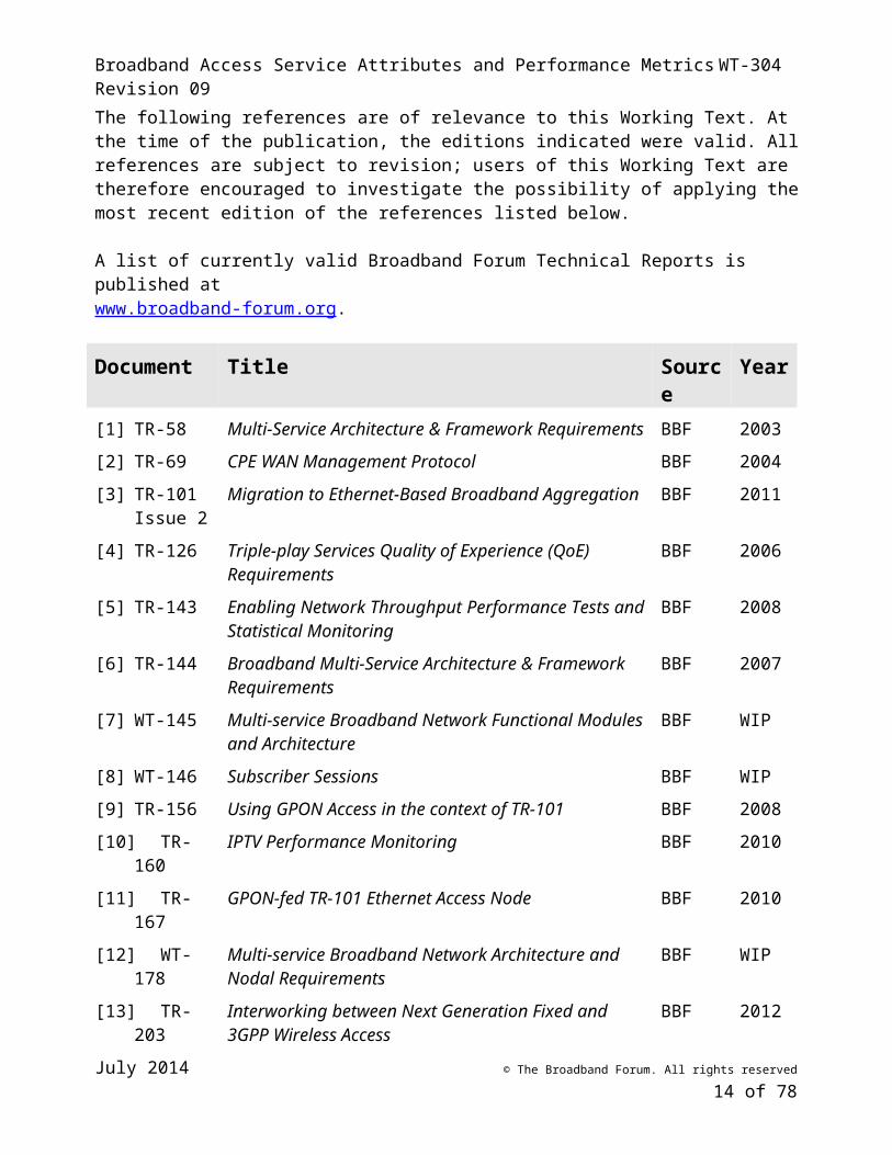
The following references are of relevance to this Working Text. At the time of the publication, the editions indicated were valid. All references are subject to revision; users of this Working Text are therefore encouraged to investigate the possibility of applying the most recent edition of the references listed below.
A list of currently valid Broadband Forum Technical Reports is published at www.broadband-forum.org.
Document Title Source Year[1] TR-58 Multi-Service Architecture & Framework Requirements BBF 2003
[2] TR-69 CPE WAN Management Protocol BBF 2004
July 2014 © The Broadband Forum. All rights reserved
11 of 55
Broadband Access Service Attributes and Performance Metrics WT-304 Revision 09
[3] TR-101 Issue 2
Migration to Ethernet-Based Broadband Aggregation BBF 2011
[4] TR-126 Triple-play Services Quality of Experience (QoE) Requirements
BBF 2006
[5] TR-143 Enabling Network Throughput Performance Tests and Statistical Monitoring
BBF 2008
[6] TR-144 Broadband Multi-Service Architecture & Framework Requirements
BBF 2007
[7] WT-145 Multi-service Broadband Network Functional Modules and Architecture
BBF WIP
[8] WT-146 Subscriber Sessions BBF WIP
[9] TR-156 Using GPON Access in the context of TR-101 BBF 2008
[10] TR-160 IPTV Performance Monitoring BBF 2010
[11] TR-167 GPON-fed TR-101 Ethernet Access Node BBF 2010
[12] WT-178 Multi-service Broadband Network Architecture and Nodal Requirements
BBF WIP
[13] TR-203 Interworking between Next Generation Fixed and 3GPP Wireless Access
BBF 2012
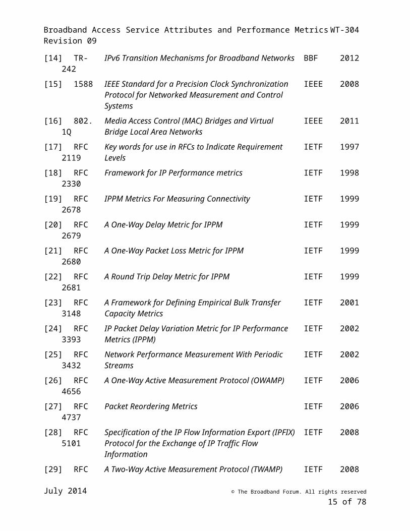
[14] TR-242 IPv6 Transition Mechanisms for Broadband Networks BBF 2012
[15] 1588 IEEE Standard for a Precision Clock Synchronization Protocol for Networked Measurement and Control Systems
IEEE 2008
[16] 802.1Q Media Access Control (MAC) Bridges and Virtual Bridge Local Area Networks
IEEE 2011
[17] RFC 2119 Key words for use in RFCs to Indicate Requirement Levels IETF 1997
[18] RFC 2330 Framework for IP Performance metrics IETF 1998
[19] RFC 2678 IPPM Metrics For Measuring Connectivity IETF 1999
[20] RFC 2679 A One-Way Delay Metric for IPPM IETF 1999
[21] RFC 2680 A One-Way Packet Loss Metric for IPPM IETF 1999
[22] RFC 2681 A Round Trip Delay Metric for IPPM IETF 1999
[23] RFC 3148 A Framework for Defining Empirical Bulk Transfer Capacity Metrics
IETF 2001
[24] RFC 3393 IP Packet Delay Variation Metric for IP Performance Metrics (IPPM)
IETF 2002
[25] RFC 3432 Network Performance Measurement With Periodic Streams
IETF 2002
[26] RFC 4656 A One-Way Active Measurement Protocol (OWAMP) IETF 2006
July 2014 © The Broadband Forum. All rights reserved
12 of 55
Broadband Access Service Attributes and Performance Metrics WT-304 Revision 09
[27] RFC 4737 Packet Reordering Metrics IETF 2006
[28] RFC 5101 Specification of the IP Flow Information Export (IPFIX) Protocol for the Exchange of IP Traffic Flow Information
IETF 2008
[29] RFC 5357 A Two-Way Active Measurement Protocol (TWAMP) IETF 2008
[30] RFC 5470 Architecture for IP Flow Information Export IETF 2009
[31] RFC 5560 A One-Way Packet Duplication Metric IETF 2009
[32] RFC 6349 Framework for TCP Throughput Testing IETF 2011
[33] RFC 6534 Loss Episode Metrics for IP Performance Metrics (IPPM) IETF 2012
[34] RFC 6673 Round Trip Packet Loss Metrics IETF 2012
[35] RFC 6703 Reporting IP Performance Metrics: Different Points of View
IETF 2012
[36] lmap-framework
A framework for large-scale measurement platforms (LMAP)
IETF
[37] lmap-information-model
Information Model for Large-Scale Measurement Platforms (LMAP)
IETF
[38] ippm-lmap-path
A Reference Path and Measurement Points for LMAP IETF
[39] ippm-registry-active
Active Performance Metric Sub-Registry IETF
[40] ippm-registry-passive
Passive Performance Metrics Sub-Registry IETF
[41] G.1020 Performance parameter definitions for quality of speech and other voiceband applications utilizing IP networks
ITU-T 2006
[42] G.8260 Definitions and terminology for synchronization in packet networks
ITU-T 2010
[43] G.8261 Timing and synchronization aspects in packet networks ITU-T 2008
[44] Y.1501 Relationships among ISDN, IP-based network and physical layer performance Recommendations
ITU-T 2004
[45] Y.1540 Internet protocol data communication service – IP packet transfer and availability performance parameters
ITU-T 2011
[46] Y.1541 Network performance objectives for IP-based services ITU-T 2011
[47] Y.1543 Measurements in IP networks for inter-domain performance assessment
ITU-T 2007
[48] Y.1544 Multicast IP performance parameters ITU-T 2008
July 2014 © The Broadband Forum. All rights reserved
13 of 55
Broadband Access Service Attributes and Performance Metrics WT-304 Revision 09
[49] Y.1560 Parameters for TCP connection performance in the presence of middleboxes
ITU-T 2003
[50] Y.1561 Performance and availability parameters for MPLS networks
ITU-T 2004
[51] Y.1563 Ethernet frame transfer and availability performance ITU-T 2009
[52] Y.1564 Ethernet service activation test methodology ITU-T 2011
[53] Y.1710 Requirements for Operation & Maintenance functionality in MPLS networks
ITU-T 2002
[54] Y.1711 Operation & Maintenance mechanism for MPLS networks ITU-T 2004
[55] Y.1730 Requirements for OAM functions in Ethernet-based networks and Ethernet services
ITU-T 2004
[56] Y.1731 OAM Functions and Mechanisms for Ethernet Based networks
ITU-T 2008
[57] MEF 10.2 Ethernet Service Attributes Phase 2 MEF 2009
[58] MEF10.2.1
Performance Attributes Amendment to MEF 10.2 MEF 2011
[59] A Report on Consumer Wireline Broadband Performance in the U.S.
FCC 2013
2.3 Definitions
Ed. Note: Once the working text is completed, the list of definitions will be trimmed to include only those that are actually used.
The following terminology is used throughout this Working Text.
Availability From TR-144 [6]: Network availability is usually described in terms of ‘unavailability events’ which have three dimensions:
a. Event frequency: how often the event occursb. Event duration: how long it takes to restore normal
operation either in terms of the average or more usefully in terms of a distribution or percentile threshold
c. Event scope: how much impact a single event has (i.e. how many customers are affected at one time or the size of the geographic region affected)
The combination of event frequency, duration and scope information can be used to derive availability percentages and other more service-specific figures of merit such as lost call minutes etc.
July 2014 © The Broadband Forum. All rights reserved
14 of 55
Broadband Access Service Attributes and Performance Metrics WT-304 Revision 09
Business Interface From WT-145 [7]: An Interface between the Regional Access Provider and a 3rd party (e.g. Mobile Carrier, Business Service Customer, NSP/ASP, etc) and serves as a hand-off interface
Data Collector A function that receives Measurement Results reported by a Measurement Agent.
Ethernet Frame (Frame)
An Ethernet Frame (or Frame) is a formatted group of octets sent using Ethernet. Metrics based on Ethernet Frames are measured at the Link layer (Layer 2).
Frame Transfer Delay
From Y.1563 [51]: Point-to-point frame transfer delay is the time required to transfer a frame from its source to its intended destination.
Frame Loss Ratio From Y.1563 [51]: The ratio of total lost Ethernet frame outcomes to total transmitted Ethernet frames in a population of interest.
Functional module From WT-145 [7]: A set of functions, which can be instantiated in a network node. A network node can contain one or more functional modules. A functional module cannot be split between network nodes. Nodal distribution of functional modules is left to WT-178.
Inter-Frame Delay Variation
From Y.1563 [51]: The IFDV (v’k) is the difference between the frame reference arrival (ck) time and the actual arrival time (ck) at the point of interest, e.g., network egress.
IP Flow From WT-146 [8]: An IP Flow is identified by a 5-tuple IP parameter traffic classifier. An IP Flow identifier forms the classification element of a traffic policy that is applied to a Session. The 5-tuples is made up of following header fields: source IP address, source port, destination IP address, destination port and protocol.
IP Session From WT-146 [8]: An IP Session is a grouping of traffic according to one or more classifiers visible at a control point, called the IP Service Edge, in the broadband network. The classifier is composed of, at a minimum the classifiers of, a Subscriber’s IP address (v4 or v6), IPv4 subnet or IPv6 prefix (with(es) or prefix(es)( for the rest of the 5-tuple set).) . This and additional Layer1 and Layer 2 parameters where appropriate.
Ed. Note: As of August 2012, this definition is incomplete in WT-146. Update definition based on text as it is finalized in the source document.
IP Packet (Packet) An IP Packet (or Packet) is a formatted group of octets sent using Internet Protocol. Metrics based on IP Packets are measured at or above the Internet layer (Layer 3).
IP Packet Delay Variation
From RFC 3393 [24]: The IPDV of a pair of packets within a stream of packets is defined for a selected pair of packets in the stream going from measurement point MP1 to measurement point MP2. The IPDV is the difference between the one-way-delay of the selected packets.
July 2014 © The Broadband Forum. All rights reserved
15 of 55
Broadband Access Service Attributes and Performance Metrics WT-304 Revision 09
IP Packet Duplicate Ratio
From Y.1540 [45]: IP packet duplicate ratio is the ratio of total duplicate IP packet outcomes to the total of successful IP packet transfer outcomes minus the duplicate IP packet outcomes in a population of interest.
IP Packet Error Ratio
From Y.1540 [45]: IP packet error ratio is the ratio of total errored IP packet outcomes to the total of successful IP packet transfer outcomes plus errored IP packet outcomes in a population of interest.
IP Packet Loss Ratio
From Y.1540 [45]: IP packet loss ratio is the ratio of total lost IP packet outcomes to total transmitted IP packets in a population of interest.
IP Packet Reordered Ratio
From Y.1540 [45]: An IP packet reordered ratio is the ratio of the total reordered packet outcomes to the total of successful IP packet transfer outcomes in a population of interest.
IP Packet Severe Loss Block Ratio
From Y.1540 [45]: An IP packet severe loss block ratio is the ratio of the IP packet severe loss block outcomes to total blocks in a population of interest.
IP Packet Transfer Delay
From Y.1540 [45]: IPTD is the time, (t2 - t1) between the occurrence of two corresponding IP packet reference events, ingress event IPRE1 at time t1 and egress event IPRE2 at time t2, where (t2 > t1) and (t2 – t1) ≤ Tmax.
IP Round Trip Delay
IP Round Trip Delay is the time between the occurrences of two corresponding IP packet reference events. The first reference event occurs when a packet is transmitted from a first network interface. The second reference event occurs when a packet, sent from a second network interface in response to its receipt of the packet sent from the first interface, is received at the first network interface. Detailed definitions of specific metrics based on IP Round Trip Delay are provided in RFC 2681 [22].
Logical Interface From WT-145 [7]: A logical interface in the broadband architecture, at a boundary between 2 functional modules. It is shown as a line between two functional modules and a combination of letters.
Not all logical interfaces need to be instantiated as a physical interface. Several functional modules may be grouped into a single physical nodal implementation. In such a case, the logical interfaces internal to the node will not be externally visible. Hence the corresponding logical interfaces are not instantiated as physical interfaces, for example, Vc, SI-NNI.
Management Server
A function that pre-configures a Measurement Agent.
Mean Opinion Score
From TR-126 [4]: The MOS is generated by averaging the results of a set of standard, subjective tests where a number of users rate the quality on a five point scale from 1 (Bad / Very Annoying) to 5 (Excellent / Imperceptible impairments). The MOS is the arithmetic mean of all the individual scores.
July 2014 © The Broadband Forum. All rights reserved
16 of 55
Broadband Access Service Attributes and Performance Metrics WT-304 Revision 09
Measurement Agent
A function that performs Measurement Tasks under the direction of a Measurement Controller.
Measurement Controller
A function that configures a Measurement Agent.
Measurement Instruction
The description of Measurement Task(s) for a MA to perform and the details of the Report(s) for it to send. It is the collective description of the of Measurement Schedules, Measurement Task configurations, the configuration of the Report Channel(s) and details of Suppression (if any).
Measurement Method
A process for measuring the value of a Performance Metric. This process may involve multiple MAs participating in various roles specific to the Measurement Method.
Measurement Peer A function that performs Measurement Tasks in concert with one or more Measurement Agents or Measurement Peers. A Measurement Peer does not communicate with a Measurement Controller.
Measurement Result
A value resulting from the execution of a Measurement Task.
Measurement Schedule
A set of Measurement Task configurations and the timing of when they should be performed, configured in a MA for use in executing Measurement Tasks.
Measurement Suppression
An element in the Measurement Instruction that temporarily stops (suppresses) Active Measurement Tasks.
Measurement Task A single instance of a Measurement Method role executed at a defined time and with defined parameter values.
Network node From WT-145 [7]: A physical, self contained element of a broadband network.
Examples: a DSLAM, an aggregation switch, etc.
Performance Measurement Framework
Definition of the architecture, the functions, and how the functions interwork, to enable performance measurements using standards-based mechanisms.
• The Performance Measurement Framework should facilitate widespread deployment of Measurement Agents within Service Providers’ networks, in subscribers’ premises networks, and at other locations.
Performance metric A parameter whose value is determined in the process of measuring performance.
• Performance Metrics are definitions, not values. Values resulting from specific measurements are referred to as measurement results.
July 2014 © The Broadband Forum. All rights reserved
17 of 55
Broadband Access Service Attributes and Performance Metrics WT-304 Revision 09
Physical interface From WT-145 [7]: A physical instantiation of a Logical Interface. It is externally visible and may host one or several logical interfaces. Example E-NNI, V.
Quality of Experience
From TR-126 [4]: The overall performance of a system from the point of view of the users. QoE is a measure of end-to-end performance at the services level from the user perspective and an indication of how well the system meets the user’s needs.
Quality of Service From TR-126 [4]: A measure of performance at the packet level from the network perspective. Quality of Service (QoS) also refers to a set of technologies (QoS mechanisms) that enable the network operator to manage the effects of congestion on application performance as well as providing differentiated service to selected network traffic flows or to selected users.
Reference Point From WT-145 [7]: A reference point is a ‘place’ inside an architecture, where one or more logical, physical, or business interfaces can be instantiated. A reference point can be internal or can be located at a given physical interface
Replicated IP Packet Ratio
From Y.1540 [45]: The replicated IP packet ratio is the ratio of total replicated IP packet outcomes to the total of successful IP packet transfer outcomes minus the replicated IP packet outcomes in a population of interest.
Report Channel The address and security information configured in an MA to communicate with a Data Collector.
Service Attribute A parameter that describes a characteristic of a service.
• Service Attributes are definitions, not values. By assigning values to a set of Service Attributes, an SP describes a service.
• Example: “Provisioned Maximum Down Capacity” is a Service Attribute. An example value assigned for a given service is “50 Mbps.”
Spurious IP Packet Rate
From Y.1540 [45]: Spurious IP packet rate at an egress MP is the total number of spurious IP packets observed at that egress MP during a specified time interval divided by the time interval duration.
Suppression The temporary cessation of all or a subset of Measurement Tasks.
2.4 Abbreviations
This Working Text uses the following abbreviations:
AN Access NodeASP Application Service Provider
July 2014 © The Broadband Forum. All rights reserved
18 of 55
Broadband Access Service Attributes and Performance Metrics WT-304 Revision 09
B-NT Broadband Network TerminationBE Best EffortBER Bit Error RateBNG Broadband Network GatewayCFM Connectivity Fault ManagementCWMP CPE WAN Management ProtocolCoS Class of ServiceCPE Customer Premises EquipmentCPN Customer Premises NetworkDDOS Distributed Denial Of ServiceDHCP Dynamic Host Configuration ProtocolDHD Dual Homed DeviceDHN Dual Homed NetworkDiffserv Differentiated ServicesDLC Digital Loop CarrierDSCP Differentiated Services (Diffserv) Code PointDSL Digital Subscriber LineDSLAM Digital Subscriber Line Access MultiplexerEFP Ethernet Flow PointFCAPS Fault, Configuration, Accounting, Performance, and SecurityFLR Frame Loss RateFTD Frame Transfer DelayIEEE Institute of Electrical and Electronics EngineersIETF Internet Engineering Task ForceIFDV Inter-Frame Delay VariationIP Internet ProtocolIPDR Internet Protocol Detail RecordIPDR Internet Protocol packet Duplicate RatioIPDV Internet Protocol packet Delay VariationIPER Internet Protocol packet Error RatioIPIBR Internet Protocol packet Impaired Block RatioIPIIR Internet Protocol packet Impaired Interval RatioIPLR Internet Protocol packet Loss RatioIPOR Octet-based IP packet RateIPPR Internet Protocol Packet RateIPRE Internet Protocol packet transfer Reference Event
July 2014 © The Broadband Forum. All rights reserved
19 of 55
Broadband Access Service Attributes and Performance Metrics WT-304 Revision 09
IPRR Internet Protocol packet Reordered RatioIPSLB Internet Protocol packet Severe Loss Block outcomeIPSLBR Internet Protocol packet Severe Loss Block RatioIPTD Internet Protocol packet Transfer DelayIPv4 Internet Protocol version 4IPv6 Internet Protocol version 6ISP Internet Service ProviderITU-T International Telecommunications Union – Telecommunication Standardization
SectorLAN Local Area NetworkMA Measurement AgentMAC Medium Access ControlMEP Maintenance Association End PointMOS Mean Opinion ScoreMP Measurement PointMPLS Multi-Protocol Label SwitchingMSBN Multi-Service Broadband NetworkMTBISO Mean Time Between IP Service OutagesMTTISR Mean Time To Internet protocol Service RestoralNAT Network Address TranslationNIC Network Interface CardNNI Network to Network InterfaceNSP Network Service ProviderNTE Network Termination EquipmentPDV Packet Delay VariationPESQ Perceptual Evaluation of Speech QualityPLR Packet Loss RateQoE Quality of ExperienceQoS Quality of ServiceRFC Request For CommentsRG Routing Gateway or Residential GatewayRTT Round Trip TimeSLA Service Level AgreementSP Service ProviderTCP Transmission Control ProtocolUDP User Datagram Protocol
July 2014 © The Broadband Forum. All rights reserved
20 of 55
Broadband Access Service Attributes and Performance Metrics WT-304 Revision 09
UNI User to Network Interface
July 2014 © The Broadband Forum. All rights reserved
21 of 55
Broadband Access Service Attributes and Performance Metrics WT-304 Revision 09
3 Working Text Impact
3.1 Energy Efficiency
WT-304 has no impact on energy efficiency.
3.2 IPv6
WT-304 IP metrics can be collected over IPv6 and well as IPv4.
3.3 Security
WT-304 introduces a number of security considerations and related requirements. These are discussed in detail in Section 8.
3.4 Privacy
WT-304 introduces a number of privacy considerations and related requirements. These are discussed in detail in Section 9.
4 Introduction
There are many types of broadband services, spanning a wide range of different functions and performance capabilities. While this variety is beneficial in that the consumers of these services have a wide range of choices, it can also sometimes be confusing. Even for a single type of service such as Internet access, there are wide variations in marketed speeds, and consumers may not be sure what level of performance they need. In addition, marketing materials from different providers may use generic terms like “speed” in different ways, and other attributes such as usage limits may not be highlighted. As a result, services that seem similar on paper can actually differ significantly in terms of performance or quality of experience.
It can also be challenging to verify how a service’s actual performance compares to its specification. For example, the performance may be specified between points at which there is no direct measurement capability, such as “from the interface between the customer and the Service Provider’s network to the interface between the Service Provider’s network and the Internet.” The service may also be specified statistically, meaning that verification of performance could require multiple measurements made from many points in the network.
The above issues can make it difficult for potential customers to compare service offerings from different providers, or even in some cases to understand the differences between levels of service offered by the same provider. Further, once a user subscribes to a given service, it can be difficult to interpret the performance delivered by that service. The effects of the issues are not limited to subscribers – Service Providers can also be limited in their ability to measure performance at many different network nodes, or in some cases to troubleshoot and isolate performance issues quickly to a single network connection or node.
July 2014 © The Broadband Forum. All rights reserved
22 of 55
Broadband Access Service Attributes and Performance Metrics WT-304 Revision 09
This document provides a framework that enables a consistent, industry-wide approach to service attributes definition and performance measurement that can resolve the issues listed above. It includes:
An architecture specifying the functional modules (and the requirements on those modules) necessary for scalable, consistent measurement of network and service performance,
Descriptions of the relevant measurement endpoints, , their locations within the network, and requirements for specifying them,
Description of a set of service attributes that can be used consistently across different services and networks,
Descriptions of performance metrics and the related measurement methods needed to enable consistent measurement of service and network performance,
Informational examples showing how the framework can be used in different parts of the network for different purposes,
It is hoped that specification of a minimum necessary level of common functionality for Measurement Agents (MAs) should facilitate the broad adoption of MAs where they are useful for measuring network performance at a large scale, including within residential gateways and other nodes at or near the network edge.
4.1 Use Cases
The use cases below focus on how this framework may have value to different users – in particular, to Service Providers, end users, and third parties.
4.1.1 Service Provider service monitoring
By deploying Measurement Agents within residential gateways and other devices at the network edge as well as at peering points and at other key nodes within their networks, Service Providers gain the capability to directly measure the performance of their networks and of the services provided over those networks. A Service Provider having a Measurement Agent on most or all RGs can use sampling to continuously monitor service performance on a statistical basis. SPs can zero in on portions of the network that require additional scrutiny based on statistical results without having to deploy additional equipment to do so. The results of such monitoring can be used for various purposes such as scheduling maintenance and network upgrades or to initiating troubleshooting.
4.1.2 Subscriber testing
Service Providers can use the infrastructure defined by this framework to make both service attribute information and performance measurement capabilities available to their subscribers. Subscribers who have knowledge of their service attributes are better equipped to understand the capabilities and limitations of the service, and can use that information to determine, for example, what applications they can reasonably run or when it may be time to upgrade. Subscribers who can measure the performance of their services are better equipped to differentiate between performance issues on their Service Providers’ networks and problems due to other conditions, either within their own residential networks or due to external causes such as congestion at the far end server.
July 2014 © The Broadband Forum. All rights reserved
23 of 55
Broadband Access Service Attributes and Performance Metrics WT-304 Revision 09
Subscribers may also glean valuable insight into the performance of their own residential networks, and how to improve that performance, using tools facilitated by the framework. Service Providers that provide those tools may experience increased customer satisfaction as a result.
4.1.3 Troubleshooting and Diagnostics
When network or service issues do occur, the infrastructure defined by the framework can make troubleshooting easier and faster. Measurement Agents deployed at nodes across the network can allow rapid isolation of a problem to a specific node or connection. This troubleshooting capability can apply in both the Service Provider’s network and within the residential or business customer’s network.
4.1.4 3rd party measurements
The large scale statistical sampling enabled by widespread implementation of this framework is potentially useful to third parties in addition to Service Providers and their customers. Regulators and researchers may see value in the ability to sample performance on a large scale across multiple networks, and to correlate measurement results with service attributes. Third party measurements could use Measurement Agents distributed by the third party in either hardware or software form, or could make use of the test infrastructure deployed by the Service Provider. While the legal, technical and social issues associated with third party testing are outside the scope of this document, we recognize that this use case holds value for a number of interested parties.
4.2 Concepts
WT-304 addresses multiple concepts related to the definition and measurement of broadband performance. The first concept is Service Attributes, which define the parameters that describe characteristics of a service. Service Attributes define parameters but do not assign values to them. By assigning values to the Service Attributes that apply to a given service and then making those values available (for example, via a web page), a Service Provider can help its subscribers understand the performance expected for the service. Service Attributes can also help potential subscribers as well as interested third parties compare different services.
The remaining concepts address the measurement of broadband performance. They are:
• Performance Metrics, which define the parameters whose values are determined in the process of measuring performance. Metrics define parameters (for example, “the packet latency between point A and point B”) but do not assign values to them. Values resulting from performance measurements are referred to as measurement results. Performance Metrics are defined to support repeatability of performance measurements, allowing the results from such measurements to be compared across time, between similar services on the same network, and across different networks.
• Measurement Methods, which define the processes used to perform measurements.
• A Performance Measurement Framework which defines and specifies requirements for the functions in the WT-304 architecture so that they interwork with each other via standards-
July 2014 © The Broadband Forum. All rights reserved
24 of 55
Broadband Access Service Attributes and Performance Metrics WT-304 Revision 09
based mechanisms. The Performance Measurement Framework should enable the widespread implementation and deployment of Measurement Agents (MAs) within service providers’ networks, in subscribers’ premises networks, and at other locations.
Service Attributes and Performance Metrics are different things. Service Attributes define the published characteristics of a service, while Performance Metrics describe the observed performance of a service or of a network segment. For example, a given service might have a Service Attribute for “Provisioned Maximum Down Capacity.” One example of a Performance Metric and associated Measurement Method that may be used to measure a service’s performance relative to that Attribute is specified in RFC 6349, which defines a framework for TCP throughput testing. The functions and interworking processes to support the Measurement Method are defined by the Performance Measurement Framework. Finally, some post-processing of measurement results (which is out of scope for WT-304 but which is discussed in Appendix II) may be performed to generate a set of statistics that characterize the performance of the service relative to “Provisioned Maximum Down Capacity.”
Neither service attributes nor performance measurement is a new concept. The value that this framework adds to those concepts is described below:
• Specification and availability of service attributes. WT-304 specifies Service Attributes that promotes clarity in defining services, while allowing for variation in how those services are defined. The specification facilitates interfaces and applications to make those attributes available to both subscribers and to third parties where appropriate. This has several benefits:
• Reports have indicated [59] that a high percentage of consumers do not know the speed of the broadband service to which they have subscribed. Making service attributes available in a consumer friendly format increases transparency.
• A defined set of Service Attributes helps to ensure that third parties such as regulators or researchers have consistently defined data, facilitating meaningful comparisons of data from different Service Providers.
• Specification of test parameters. By formalizing the specification of test parameters, WT-304 enables consistency and repeatability in the execution of the associated measurements. This consistency allows multiple iterations of a given measurement, or measurement results from a sample population of similar test segments, to be aggregated as appropriate. It also allows those results to be compared to results from similar measurements performed on other test segments, or even on other networks. Note that “repeatability” does not mean that different measurement results will be identical, even when performed on the same test segment. It does mean, however, that variation in measurement results will be due to variations in network conditions, rather than to variations in the Measurement Method.
• Interworking between Measurement Agents. Many tests require coordination between the Measurement Method roles at each end of the network segment under test. This framework specifies the requirements for interworking so that MAs from different vendors and in
July 2014 © The Broadband Forum. All rights reserved
25 of 55
Broadband Access Service Attributes and Performance Metrics WT-304 Revision 09
different networks can: identify the tests to be performed including all required parameters; perform test admission control as necessary; execute the tests consistently; and provide diagnostic response codes as needed (for example, if an MA must reject a test request).
• Service states. A Measurement Agent can use data about the current state of a service to determine whether or when to initiate previously scheduled tests on that service. The data can include: whether the service is currently available (or in an outage or maintenance state); usage to date for the current billing period; and user traffic.
• Measurement control and reporting. The WT-304 Performance Measurement Framework specifies how tests are initiated and scheduled by a Measurement Controller, and how MAs are managed by a Management Server. It also specifies how management and control of MAs is coordinated, for example when the Management Server and the Measurement Controller are within different administrative domains. This facilitates large scale testing and monitoring within a Service Provider’s network, as well as testing implemented cooperatively between a Service Provider and a third party.
• Security. The Performance Measurement Framework specifies requirements for the security of the test control, initiation and reporting mechanisms.
• Privacy. The Performance Measurement Framework specifies requirements for the protection of Personally Identifiable Information (PII), as well as for the privacy of user traffic.
An important feature in WT-304 is interworking between MAs from different vendors, controlled from different administrative domains, or deployed within different networks. The measurement of test segments where the two endpoints lie within different networks is within scope and is expected to be encountered frequently. One example would be an “end-to-end” measurement that extends from an MA within a subscriber’s premises network to an MA in a remote node which may or may not lie within the service provider’s network.
WT-304 supports both scheduled testing and on-demand testing. Tests can be scheduled in an MA for initiation at specific times or at defined intervals without further intervention from a Measurement Controller, as would be typical in a large scale monitoring or measurement program. In addition, tests can be initiated on demand to facilitate user requests or service troubleshooting.
The scope of WT-304 includes both active and passive measurements. Active measurements generate synthetic test traffic for the purpose of measuring performance using known traffic parameters. Passive measurements do not generate any traffic; instead they are based on observation of user traffic. One potential issue with passive measurements is privacy of user data. It is important that any data that may compromise user privacy – including but not limited to source and destination IP addresses and payload data – be excluded from test results or related messages, and that such data not be stored within the MA longer than required to extract the relevant measurement results.
July 2014 © The Broadband Forum. All rights reserved
26 of 55
Broadband Access Service Attributes and Performance Metrics WT-304 Revision 09
4.3 Related work
Ed. note: Includes primary sources for elements of the framework – e.g., performance metrics and test methodologies from IETF.
4.3.1 Broadband Forum documents
• Ed. note: SD-323 – BBH solutions to instantiate WT-304• TR-069• TR-101 / TR-156 / TR-167• TR-126• TR-143• WT-145?• TR-160?• WT-178
4.3.2 Other projects
The content of this document was developed in close coordination with work conducted in the IETF Large-Scale Measurement of Broadband Performance (LMAP) working group. To a large extent, WT-304 and the LMAP Framework, LMAP Use Cases, and LMAP Information Model are consistent, but there are differences due to differences in scope.
In addition, work in the IETF IP Performance Metrics (IPPM) Working Group is taken into account.
5 Performance Measurement Framework
5.1 Functions
The major operational functions identified by the Performance Measurement Framework are:
Measurement Agent (MA): Performs Measurement Tasks under the direction of a Measurement Controller. The Measurement Agent registers with and receives Instructions from a Measurement Controller, performs Measurement Tasks (perhaps in concert with one or more other Measurement Agents and/or Measurement Peers), and reports Measurement Results to one or more Data Collectors.
Measurement Peer: Performs Measurement Tasks in concert with one or more Measurement Agents (and perhaps other Measurement Peers). A Measurement Peer does not communicate with a Measurement Controller.
Measurement Controller: Controls the scheduling and configuration of Measurement Tasks within a Measurement Agent.
Data Collector: Receives Measurement Results reported by a Measurement Agent .
July 2014 © The Broadband Forum. All rights reserved
27 of 55

Broadband Access Service Attributes and Performance Metrics WT-304 Revision 09
Management Server: Manages and configures a physical device or network element. Examples include a TR-069 ACS (Auto-Configuration Server), or an EMS (Element Management System).
WT-304 does not limit the operational functions that may coexist in a single device. As one example, a Management Server and a Measurement Controller may coexist in the same device. As another example, two or more Measurement Agents and/or Measurement Peers may coexist in the same device. This is more likely to occur in unmanaged devices such as personal computers, tablets, laptops, and smartphones. Where a Service Provider manages the physical device, it may be operationally simpler to implement all Measurement Method roles within a single MA. A third example combines a Measurement Controller, Measurement Agent and Data Collector in an integrated application for use in personal devices.
It is not necessary for all of these operational functions to be present for every measurement scenario. While a WT-304 scenario will contain at least one Measurement Agent acting under the direction of a Measurement Controller, the MA may be in an unmanaged device, negating the need for a Management Server. Measurement Tasks may be performed using one or two Measurement Agents, without a Measurement Peer. Finally, a Measurement Agent will not always send Measurement Results to a Data Collector. Figure 1 shows a use case where all of these functions are present.
Figure 1 – Example Use Case with all Functional Modules
A Measurement Agent is associated with and operates under instructions from a Measurement Controller, and has a set of capabilities known to the Controller. A Measurement Peer has no such association. This is the primary defining difference between the two types of measurement endpoints.
Depending on the nature of the Measurement Task being executed, a Measurement Agent may perform the Task on its own or with one or more other Agents or Peers. As long as at least one
July 2014 © The Broadband Forum. All rights reserved
28 of 55
Broadband Access Service Attributes and Performance Metrics WT-304 Revision 09
Measurement Agent is involved, the Task is in scope for WT-304. Measurement Peer-to-Measurement Peer measurements are out of scope.
5.1.1 Measurement Agent (MA)
The MA receives its directions from the Measurement Controller in the form of an Instruction that may contain any or all of the following elements:
• One or more Measurement Task configurations defining the Measurement Method role, parameter values, and other information to use for a given set of Measurement Tasks.
• One or more Report Channels defining the address and security information for a Data Collector to which Measurement Results should be reported.
• One or more Report Schedules defining the Report Channel, the schedule, and other information for transferring data to a Data Collector.
• One or more Measurement Schedules defining what Measurement Tasks to run and the schedule on which to run them.
• Suppression information defining Measurement Tasks to be temporarily suppressed from running (see Section 5.2.3).
Before it can be used to execute Measurement Tasks, a MA must be associated with a Measurement Controller. A MA may be pre-configured to register with a specific Measurement Controller, or if managed it may be configured to do so by a Management Server. The only times that a MA is not associated with a Measurement Controller are before it registers or when it is switching its association from one Controller to another.
[R-1] A MA must be associated with exactly one (1) Measurement Controller.
[R-2] A MA MUST be associated with no more than one Measurement Controller at any given point in time.
[R-3] A MA MUST register with its configured Measurement Controller whenever the MA becomes operationally active.
[R-4] A MA MUST not perform any Measurement Tasks unless it is currently registered with its Measurement Controller.
[R-5] A MA MUST have no more than one active Instruction. One Instruction can contain multiple Measurement Task configurations, Measurement Schedules and reporting options.
[R-6] A MA MUST be able to receive a new Instruction from its Measurement Controller.
[R-7] A MA MUST be able to send the active Instruction to its Measurement Controller on demand.
July 2014 © The Broadband Forum. All rights reserved
29 of 55
Broadband Access Service Attributes and Performance Metrics WT-304 Revision 09
[R-8] A MA MUST be able to receive an update to the active Instruction from its Measurement Controller with regard to the following: Adding a Measurement Task configuration Modifying a Measurement Task configuration Modifying the reporting of Measurement Results Modifying a measurement schedule Suppression
It is possible for a MA to report data to more than one Data Collector. This will depend on the design and configuration of the MA.
[R-9] A MA MUST be able to report Measurement Results to a Data Collector using the parameters in a stored Report Channel.
[R-10] A MA MUST support Suppression as described in section 5.2.3.
[R-11] A MA MUST be able to report its set of supported Measurement Methods to the Measurement Controller.
[R-12] A MA MUST be able to report its measurement capabilities, any measurement task failures and logging information to its Measurement Controller, in response to a request from its Measurement Controller, and on its own initiative when triggered by some local event.
Capabilities consist of information that the Measurement Controller needs to know in order to construct the MI, such as that MA’s supported Measurement Tasks. Failure information covers the MA having been unable to execute a Measurement Task or deliver a Report. Logging information concerns how the MA is operating and may help debugging.
[R-13] The set of measurement capabilities within a MA SHOULD be extensible and capable of being updated.
Since many active Measurement Methods supported by a MA have the potential to disrupt network performance if misused, it is essential that the MA authenticate the Measurement Controller before accepting an Instruction from it. Similarly, since both Service Attributes and Measurement Results can contain sensitive information, it is important that the MA provide such information only to an authenticated destination and that it do so over a secure channel.
[R-14] A MA MUST authenticate a Measurement Controller before accepting and storing an Instruction from it.
[R-15] A MA MUST authenticate a Measurement Controller before sending Capabilities or Service Attributes to it.
[R-16] A MA MUST authenticate a Data Collector before sending Measurement Results or Service Attributes to it.
July 2014 © The Broadband Forum. All rights reserved
30 of 55
Broadband Access Service Attributes and Performance Metrics WT-304 Revision 09
[R-17] A MA MUST use a secure channel for communications with a Measurement Controller or a Data Collector.
5.1.2 Measurement Peer
A Measurement Peer is any measurement endpoint participating in a Measurement Task which is not associated with a Measurement Controller. The Measurement Method roles supported by a Measurement Peer may or may not be known to the organization coordinating measurements through the Performance Measurement Framework – any such knowledge is transferred out-of-scope. A Measurement Peer may or may not even have capabilities specific to Measurement Tasks. An important subclass of Measurement Peers consists of hosts that are unaware of WT-304 but that respond to non-test-specific activity such as pings, DNS queries or http requests. Therefore, this framework does not include requirements for a Measurement Peer.
Since the capabilities of a Measurement Peer are not defined, a Measurement Agent performing a measurement with a Measurement Peer should be prepared for unexpected or missing responses.
5.1.3 Measurement Controller
The Measurement Controller is responsible for configuring and scheduling the execution of Measurement Tasks, and the reporting of the associated Measurement Results, in the Measurement Agents under its direction.
[R-18] A Measurement Controller MUST be able to send Measurement Task configurations to the MAs under its direction.
[R-19] A Measurement Controller MUST be able to send Measurement Schedules to the MAs under its direction.
[R-20] A Measurement Controller MUST be able to send Control and Report Channels to the MAs under its direction.
[R-21] A Measurement Controller MUST be able to send Suppression information to a MA under its direction.
[R-22] A Measurement Controller MUST be able to request that any MA under its direction report its capabilities, failure information, logging information, and active Instruction.
[R-23] A Measurement Controller MUST authenticate a Measurement Agent before sending an Instruction to it.
[R-24] A Measurement Controller MUST use a secure channel for communications with a MA.
July 2014 © The Broadband Forum. All rights reserved
31 of 55
Broadband Access Service Attributes and Performance Metrics WT-304 Revision 09
5.1.4 Data Collector
A Data Collector may receive reports on varying schedules from many different MAs. So long as the Data Collector can authenticate the MA for a given transaction, it will accept the data provided in that transaction.
The use of the data after it has been stored in the Data Collector is out of scope for WT-304. However, access to the data is in scope. Since the data may contain sensitive information the Data Collector must prevent access from unauthorized users.
[R-25] A Data Collector MUST authenticate a Measurement Agent before receiving Measurement Results from it.
[R-26] A Data Collector MUST be able to receive and accept Measurement Results from an authenticated Measurement Agent.
[R-27] A Data Collector MUST use a secure channel for communications with a MA.
[R-28] A Data Collector MUST limit access to stored data to authorized entities.
[R-29] A Data Collector MUST log all transaction attempts.
5.1.5 Management Server
The Management Server has two functions within the scope of WT-304. The first is configuration of the Measurement Agent(s) in managed devices to support the MA’s registration with the desired Measurement Controller. The second function is enabling or disabling the Measurement Agent.
[R-30] The Management Server MUST be able to configure the Measurement Agent so that it registers with the desired Measurement Controller.
[R-31] The Management Server MUST be able to enable and disable the Measurement Agent.
[R-32] The Management Server MUST authenticate a Measurement Agent before configuring it.
[R-33] The Management Server MUST use a secure channel for communications with a MA.
5.2 Protocols and Data Structures
July 2014 © The Broadband Forum. All rights reserved
32 of 55
Broadband Access Service Attributes and Performance Metrics WT-304 Revision 09
5.2.1 Management Server Protocol and Data Structures
[R-34] A protocol and data structure intended to allow a Management Server to communicate with a MA MUST allow the Management Server to configure parameters exposed to it by a Measurement Agent.
[R-35] A protocol and data structure intended to allow a Management Server to communicate with a MA SHOULD allow for the Measurement Controller function to exist in the Management Server.
5.2.2 Measurement Controller Protocol and Data Structure
When a Measurement Controller receives a registration request from a Measurement Agent, it must assume that any previous Measurement Tasks sent to that Measurement Agent have been erased from the Measurement Agent configuration.
[R-36] A protocol and data structure intended to allow a Measurement Controller to communicate with a MA MUST allow the set of supported measurement capabilities of the MA to be requested by the Measurement Controller.
[R-37] A protocol and data structure intended to allow a Measurement Controller to communicate with a MA MUST allow the Measurement Controller to configure Measurement Task parameters within the MA.
[R-38] A protocol and data structure intended to allow a Measurement Controller to communicate with a MA MUST allow the Measurement Controller to define one or more test schedules.
5.2.3 Suppression of scheduled measurements
Suppression refers to the ability of the Measurement Controller to send a suppress message to the MA that instructs the MA to temporarily suspend the schedule of Measurement Tasks. This means that the MA temporarily does not begin some or all new Measurement Tasks. Suppression ends either in response to an explicit unsuppress message or at the time indicated in the suppress message. Suppression can be used when the measurement system wants to eliminate inessential traffic, for example after a major network incident. Only one suppression message can exist at a time. A new suppression message completely replaces the previous one.
[R-39] A protocol and data structure intended to allow a Measurement Controller to communicate with a MA MUST support sending suppress messages from the Measurement Controller to MAs.
[R-40] A new suppress message MUST completely replace the previous one.
[R-41] A protocol and data structure intended to allow a Measurement Controller to communicate with a MA MUST support a parameter (the suppression flag) in each
July 2014 © The Broadband Forum. All rights reserved
33 of 55
Broadband Access Service Attributes and Performance Metrics WT-304 Revision 09
Measurement Task configuration, identifying it as either a “suppress” or “do not suppress” task. This flag MUST only be taken into account when a default suppression message is sent i.e. one with NO optional parameters included.
[R-42] An MA MUST respond to the default suppression message in the following ways: NOT start any Measurement Tasks for which the suppression flag is set to “suppress.” Measurement Tasks for which the suppression flag is set to “do not suppress” MUST not
be affected. Suppression MUST start immediately. Suppression MUST continue until the MA receives an unsuppress message.
[R-43] A suppress message MUST also be able to specify a set of Measurement Tasks and/or Measurement Schedules to be suppressed. If any Measurement Tasks and/or Measurement Schedules are specified, the specified Tasks and/or Schedules MUST be suppressed, all other Tasks MUST NOT be suppressed, and all suppression flag settings MUST be ignored.
[R-44] A suppress message MUST be able to specify a start time and/or end time for suppression.
[R-45] A suppress message MUST be able to request that a MA ceases currently running Measurement Tasks. The MA does not necessarily have to accede to such requests.
[R-46] A protocol and data structure intended to allow a Measurement Controller to communicate with a MA MUST support the Measurement Controller sending unsuppress messages to MAs.
[R-47] An unsuppress message MUST cease all suppression in that MA. There is no mechanism for unsuppressing a specified subset of tasks.
5.3 Measurement endpoints
Measurement Agents or Measurement Peers are located at the ends of the segment under test, which are generically referred to as the measurement endpoints. There are two main contextual characteristics to measurement endpoints that are significant:
1. Location in the communication path2. Geographical location of the end point
Given the specific relevance of these characteristics and their impact on the meaning of test results, it is necessary to couple the endpoint locations and test results.
5.3.1 Location Attribute (Mapping to Broadband Forum reference points)
The following measurement reference points have been identified by the Broadband Forum in cooperation with regulatory agencies. Any Consumer, Regulatory, or other concern may reach out to the Broadband Forum and propose additional measurement reference points as needed. The
July 2014 © The Broadband Forum. All rights reserved
34 of 55
Broadband Access Service Attributes and Performance Metrics WT-304 Revision 09
purpose of these measurement reference points is to provide an equivalent point in the communication flow of any applied technology.
It should be noted that two types of tests may be conducted: the first involves testing from one measurement reference point to another, and the second is an observation of local conditions at a given measurement reference point.
Figure 2 identifies the measurement reference points. In some cases (A-10, Va, and T), the measurement reference points correspond to architecture reference points specified by the Broadband Forum. In other cases, there are no corresponding Broadband Forum architecture reference points.
Internet Source Internet
Service Network /
CDN
Regional Broadband
NetworkAccess Network
Customer Network (LAN)
Customer Equipment
Internet Source
Internet Drain
Regional Test Point
(A-10)
Metro Test Point
(Va)
User Network Interface
(T)Customer
End Device
Internal Regional
Test Point
Internal Access
Test Point
Figure 2 – Measurement reference points
Table 1 identifies the code associated with each measurement reference point.
Table 1 – Measurement reference point codesCode Measurement Reference
Point NameDescription
STP Internet Source Test Point Test point located at an Internet Host.IDTP Internet Drain Test Point Test Point located at the ISP interface to
the InternetRNTP Regional Network Test
PointTest point located at an interface between the Regional Broadband network and a Service network (applies for CDN and other host sources)
IRTP Internal Regional Test Point
Test point located within the ISP’s Regional network.
MTP Metro Test Point Test point located at the interface between the Access network and the Regional Broadband network.
IATP Internal Access Test Point Test point located within the ISP’s Access network.
UNITP User Network Interface Test Point
Test point located at the interface between the Access network and the Customer Home network.
CEDTP Customer End Device Test Point
Test point located on a Customer home network device.
July 2014 © The Broadband Forum. All rights reserved
35 of 55
Broadband Access Service Attributes and Performance Metrics WT-304 Revision 09
6 Access Service Attributes
Because testing of an end user’s broadband access service is a key use case for this testing framework, it is important that the attributes associated with this access service can be clearly and unambiguously identified for purpose of comparison to performance measures. Access services have three types of attributes, those that must be configured during the setup of the service, those that result from the type of equipment, protocols, and distance involved with providing the service, and those that describe the service as it is sold. Configured attributes such as capacity, interface type, and protocol are common to all access services. Service Level Agreements (SLAs) consist of performance metrics that are guaranteed in the context of a sales contract.
Only service attributes that can impact the interpretation of performance measurements are listed in this section.
SLAs (which normally only appear with business class service), cover how a service can be expected to perform as a condition of the sale. Best Effort services typically do not include SLAs - however this does not mean that their performance cannot be measured.
6.1 Static Access Service Attributes
A set of static access service attributes is listed in Table 2 and described in the subsections below. Not all services will have values for all of these attributes, and not all Service Providers will make all of the attributes available.
Table 2 – Static access service attributesAttribute Units Contents Description Impacts
Interpretation of...
Access Service Provider IANA
Enterprise Number
<signed integer>
IANA Enterprise Number of the Access Service Provider. IANA numbers listed at http://www.iana.org/assignments/enterprise-numbers.
All tests run across an access network;
can be used to correlate tests of
multiple end users of same access
network or for an end user to compare
individual results against results of other end users of the same access
network.
Access Service Provider name <string>
Name of the Access Service Provider Human readable non-standardized format. NA. Provided for
human readability.
Access Product Name <string>
Identifies the product the customer currently has purchased
(unique within Access Service Provider)
Tests run across an access network; can be used to aggregate
and compare tests of end users with the same access
productAnonymous <string> Access network ISP Anonymous ID Tests run across an
July 2014 © The Broadband Forum. All rights reserved
36 of 55
Broadband Access Service Attributes and Performance Metrics WT-304 Revision 09
Service Instance ID
provided for correlation and privacy(unique per access service per customer
within an access network ISP)
access network: can be used to aggregate
test results of a single end user access service
Attributes per protocol layer
Protocol Enumeration of TR-181 interface
objects
The protocol layer that the following attributes are for; capacities include the
protocol headers, except in the case of “IP payload”. It is not necessary to use TR-069 or the TR-181 data model in order to make
use of the interface naming conventions used in TR-181.
Capacity tests
Provisioned Maximum Down
Capacity
Bits per second <integer> Provisioned limit of downstream capacity at
this protocol layer Capacity tests
Provisioned Maximum Up
Capacity
Bits per second <integer> Provisioned limit of upstream capacity at
this protocol layer Capacity tests
Product Minimum Down Capacity
Bits per second <integer>
Per product claim, minimum down capacity that the access service can achieve as a
general rule at this protocol layerCapacity tests
Product Minimum Up Capacity
Bits per second <integer>
Per product claim, minimum up capacity that the access service can achieve as a
general rule at this protocol layerCapacity tests
Provisioned Maximum Down
Burst
Bits per second <integer> Provisioned burst limit of downstream
capacity at this protocol layer Capacity tests
Provisioned Maximum Up
Burst
Bits per second <integer> Provisioned burst limit of upstream capacity
at this protocol layer Capacity tests
Usage limit type
Enumeration of “Unlimited”, “Capped”, “Metered”
Type of usage limit imposed on the access service at this protocol layer. This
parameter may only exist or be populated at one of the protocol layers.
Capacity tests. Also impacts whether or
not to run bandwidth-intensive
tests.
Volume cap MBytes <integer>If “Usage limit” = Capped then volume cap
per billing cycle at this protocol layer; otherwise null
Capacity tests. Also impacts whether or
not to run bandwidth-intensive
tests.
Throttled Maximum Down
Capacity
Bits per second <integer>
If “Usage limit” = Capped and usage is throttled after the cap is exceeded, this
represents the limit of downstream capacity when the throttle is in place.
Capacity tests
Throttled Maximum Up
Capacity
Bits per second <integer>
If “Usage limit” = Capped and usage is throttled after the cap is exceeded, this
represents the limit of upstream capacity when the throttle is in place.
Capacity tests
Marketed Expectation
Enumeration of “Maximum”, “Minimum”
Marketed expectation of the access service, that can generally achieved at this protocol
layer; this is either the Maximum or Minimum marketed capacities.
Capacity tests
Lower Layer Protocols
Comma delimited enumeration of
The protocol(s) used below the protocol these attributes are for. It is not necessary to
Capacity tests; knowledge of the
July 2014 © The Broadband Forum. All rights reserved
37 of 55
Broadband Access Service Attributes and Performance Metrics WT-304 Revision 09
TR-181 interface objects
use TR-069 or the TR-181 data model in order to make use of the interface naming
conventions used in TR-181.
protocol at a layer (and its associated overhead) can be
used to derive approximate
capacity at other layers, if those values are not
directly provided
Access Service Supported
Higher-Layer Protocols
Comma delimited enumeration of
TR-181 interface objects
The protocol(s) that may be used above the protocol these attributes are for, but below an IP layer. As different traffic may make use of different protocol stacks, it is not a given that any particular IP packet will be
encapsulated in some or all of these protocols. It is not necessary to use TR-069 or the TR-181 data model in order to make
use of the interface naming conventions used in TR-181.
Capacity tests; knowledge of the protocol at a layer (and its associated overhead) can be
used to derive approximate
capacity at other layers, if those values are not
directly provided
6.1.1 Capacity
The information-carrying capacity or speed of a service is the rate at which the service is capable of transferring information to and from the customer. The capacity may be defined in different ways by different services. Among other possibilities, it may refer to: the speed of a dedicated medium such as a DSL connection; a peak speed on a shared medium such as wireless or coax; a provisioned speed to which a subscriber’s traffic is shaped; or the mean speed or other statistical measure to which the service is expected to perform. In addition, the network layer at which a given speed applies, and therefore the protocol overhead that is included with or excluded from the definition, is not specified.
Two service attributes are provided for capacity, differentiated by the direction of information transfer. The direction is applicable only for “single-ended” services such as Internet access that provide connectivity between a customer and a network.
Down capacity describes the information-carrying capacity of the service in the direction from the network to the customer.
Up capacity describes the information-carrying capacity of the service in the direction from the customer to the network.
6.1.2 Usage-based limits
These attributes describe the usage-based limits (if any) applied to the service. It is important for a test system to be aware of usage-based limits because test traffic (especially if the test is controlled by an entity other than the Service Provider) may be counted against such limits.
The “Usage limit” attribute identifies the type of usage limit applied to the service. The field is populated by a selection from the following list:
Unlimited: No usage limit is applied to the service.
July 2014 © The Broadband Forum. All rights reserved
38 of 55
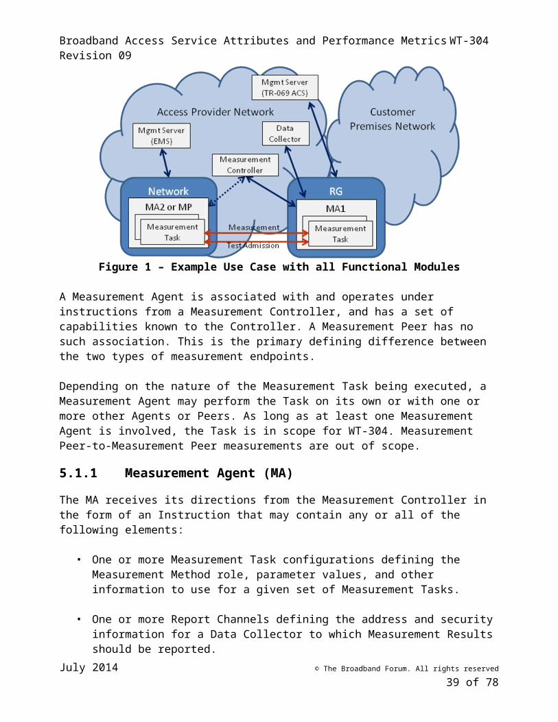
Broadband Access Service Attributes and Performance Metrics WT-304 Revision 09
Capped: The service is subjected to a volume cap per billing cycle. Metered: Usage of the service is metered (e.g., the customer is billed per MByte).
The “Volume cap” attribute quantitatively describes the billing cycle traffic volume level which triggers a response from the Service Provider.
6.2 Dynamic Access Service Attributes
Dimensions of the Access Service relevant to usage, “in maintenance,” exceeded usage limit, and “current utilization or “in use” are all relevant to both customers investigating service performance, and the results of any test conducted while those states are part of the environment being tested. As these attributes are dynamic and changing over time, they are only relevant if determined coincident to the time of the test. The list of service states is shown in Table 3.
Table 3 – Dynamic access service attributes
State Units Contents DescriptionImpacts
Interpretation of...
Current billing cycle
usageMbytes <integer>
IP packet (?) usage for this service, that applies towards a usage limit
or metered service.Capacity tests
Current datetime Datetime
The date and time of the Current usage value
Retrieved with Current month billing cycle usage as second field
6.3 Customer Premises Network (CPN) Attributes
Where one or more of the test path segments is internal to the customer premises network, it may be useful to know this and to understand whether this segment has a significant impact on a test. This requires that the segment be appropriately characterized. As with all of the other attributes, these attributes may not always be available. This table describes how to represent them if they are available.
It should be noted that it would not be appropriate to use these measures as a means of determining an accurate contribution of the CPN on a test. These measures can provide a rough idea as to the approximate contribution (e.g., large, small, negligible) of the CPN. If the desired goal is to measure a specific path that does not include the CPN, then the only way to accurately measure that path is to run a test that only goes across that specific path. However, where the contribution of the CPN is determined to be negligible, the results of tests made with and without the negligible CPN contribution will be reasonably comparable.
Table 4 – Customer premises network attributes
Attribute Units Contents DescriptionImpacts
Interpretation of...
MA network Enumeration of
July 2014 © The Broadband Forum. All rights reserved
39 of 55
Broadband Access Service Attributes and Performance Metrics WT-304 Revision 09
interface PHY
connector
“RG6”, “RJ11”, “RJ14”, “RJ45”, “radio”
MA network interface
PHY technology
Enumeration of Media Type from IEEE 1905.1, with 1905.1 OUI and variant index of organization that defines the technology
PHY technologies between MA and access
device
Comma delimited list
May be obtained through various topology discovery mechanisms.
6.4 Test Path Attributes
Independent of whether the performance testing is being done across the access service of a particular end user, there are attributes related to the end-to-end path of the test that are useful for interpreting and comparing test results. These are very similar to the attributes associated with a specific access service, but are generalized here to all links in the test path. As with access service attributes, these attributes may not always be available. This table describes how to represent them if they are available.
Table 5 – Test path link attributes
Attribute Units Contents DescriptionImpacts
Interpretation of...
Network in test path
Network IANA
Enterprise Number
<signed integer>
IANA Enterprise Number of the Service Provider(s) whose networks were in the test path. IANA numbers listed at http://www.iana.org/assignments/enterprise-numbers. A -1 value indicates the Customer Premises Network. If it is unknown whether multiple networks were in the path, or if any of the networks are unknown, an entry with -2 shall be present.
Allows test results to be
correlated with all networks in
test path
Network Name <string>
Name of the Service Provider(s) whose networks were in the path of the test. Human readable non-standardized format. The string “Customer Premises Network” is used to indicate the Customer Premises Network.
Network Role <string> Comma delimited pair of endpoints of the network segment under test. Endpoints are enumeration of measurement reference point codes from Table 1. Example:
Identifies position of
network in test path
July 2014 © The Broadband Forum. All rights reserved
40 of 55
Broadband Access Service Attributes and Performance Metrics WT-304 Revision 09
“UNITP, CEDTP”
7 Performance Metrics
RFC 2330 provides a framework for definition of IP performance metrics. Among other things it defines three general types of metrics related to measurements – singletons, samples and statistics.
Singletons. A singleton is a metric resulting from a single instance of a measurement. For a throughput metric, this could be a single measured TCP throughput over a specific interval. For delay, a singleton could be the delay measured for a specific packet.
Samples. A sample is derived from a singleton metric by defining a number of singletons as a group. The definition usually includes information about how the singletons relate to each other, such as the time intervals over which they were measured. As an example from RFC 2330, “… we might define a sample metric of one-way delays from one host to another as an hour’s worth of measurements, each made at Poisson intervals with a mean spacing of one second.”
Statistics. A statistical metric is derived by computing a statistic, such as the mean, of the singleton values in a sample metric.
Performance metrics associated with the service attributes listed in Section 6 are defined in the standards referenced below.
7.1 Capacity
Test Description
Reference (where defined)
Available Metrics Protocol layer tested
Implementation availability and uses
DSL capacity metrics
G.997.1 ATTNDRus (The current maximum attainable data rate upstream),
ATTNDRds (The current maximum attainable data rate downstream)
DSL Widespread availability; useful for all DSL lines
Ethernet capacity metrics
?? Ethernet (802.3)
TCP bulk transfer capacity (BTC) metrics
RFC 3148 TCP/IP
TCP throughput for business services
RFC 6349 Useful for testing business lines
July 2014 © The Broadband Forum. All rights reserved
41 of 55
Broadband Access Service Attributes and Performance Metrics WT-304 Revision 09
Test Description
Reference (where defined)
Available Metrics Protocol layer tested
Implementation availability and uses
HTTP download / upload
TR-143 See TR-143 HTTP/TCP/IP
Useful for testing residential lines at HTTP application layer
FTP download / upload
TR-143 See TR-143 FTP/TCP/IP
Useful for testing residential lines at FTP application layer
7.2 Delay
Test Description
Reference (where defined)
Available Metrics Protocol layer tested
Implementation availability and uses
Actual Interleaving Delay
G.997.1 Actual Interleaving Delay (Reports the actual delay of the latency path due to interleaving.)
DSL widespread
One-way Frame Delay for a Service Frame
MEF 10.2 One-way Frame Delay Performance; and One-way Mean Frame Delay Performance.
Ethernet
RFC2679 One-way packet delay IP
RFC 2681 Round trip delay ?/IP
UDP Echo Plus
TR-143 Determining delay between 2 endpoints. Can also be used to confirm IP connectivity between 2 endpoints.
UDP/IP
One-way packet (or frame) delay for a service is defined as the interval between the time that the first bit of a packet ingresses the service at the sending interface and the time that the last bit of the corresponding packet egresses the service at the receiving interface. The attribute can be applied only to packets which are delivered to the receiving interface, meaning that lost packets are excluded from the definition. Since different packets sent across a service generally experience different amounts of delay, the attribute may be specified using a statistical value such as mean packet delay. Since propagation delay is a component of packet delay, the attribute may specify different values for different pairs of sending and receiving interfaces.
July 2014 © The Broadband Forum. All rights reserved
42 of 55
Broadband Access Service Attributes and Performance Metrics WT-304 Revision 09
7.3 Packet Delay Variation or Frame Delay Range
Ed. Note: need description of why there are two types of metrics for jitter. Under what circumstances would someone use one or the other?
Test Description
Reference (where defined)
Available Metrics Protocol layer tested
Implementation availability and uses
RFC3393, RFC5481
Packet delay variation IP
MEF 10.2 One-way frame delay range Ethernet
Packet Delay Variation (PDV) or Frame Delay Range (FDR) characterizes the variation in packet (or frame) delay between a sending and a receiving interface. Like delay, PDV/FDR is specified using statistical parameters. The attribute is usually specified in terms of the difference between values of delay experienced at two different percentile levels within a population of packets.
7.4 Inter-Packet and Inter-Frame Delay Variation
Test Description
Reference (where defined)
Available Metrics Protocol layer tested
Implementation availability and uses
RFC3393, RFC5481
Inter=packet delay variation IP
MEF 10.2 Inter-frame delay variation Ethernet
Inter-Packet Delay Variation (IPDV) or Inter-Frame Delay Variation (IFDV) is the difference between the one-way delays of a pair of selected packets or frames. It is specified differently than PDV or FDR in that it specifies pairs of packets or frames to compare for each measurement rather than using single delay values for the sample population. The attribute is specified using statistical parameters, but each sample within the population is a difference value between two delays rather than a single delay.
7.5 Loss
Test Description
Reference (where defined)
Available Metrics Protocol layer tested
Implementation availability and uses
RFC2680 IP packet loss IP
July 2014 © The Broadband Forum. All rights reserved
43 of 55
Broadband Access Service Attributes and Performance Metrics WT-304 Revision 09
MEF 10.2 One way frame loss ratio Ethernet
The packet (or frame) loss ratio is the ratio of total lost packets (or frames) to total transmitted packets (or frames) in a population of interest. The Loss threshold attribute is the threshold value for this ratio specified in the SLA.
7.6 Availability
Test Description
Reference (where defined)
Available Metrics Protocol layer tested
Implementation availability and uses
Y.1540 IP service availability IP
MEF 10.2, MEF10.2.1
Availability Ethernet
The percentage of total scheduled service time that is categorized as unavailable based on packet or frame loss. The precise definition of availability may be different for different services. Carrier Ethernet services define the transition between available and unavailable periods using a sliding window mechanism with hysteresis. Recommendation Y.1540 uses a simpler definition based on an IP service unavailability function, which is used to define IP Service Availability and IP Service Unavailability parameters.
7.7 Path
Determining the path that packets take when reaching a particular test endpoint can be very important in analyzing tests that run across multiple networks. Traceroute is the best mechanism for identifying all networks and nodes that are traversed. However, since traceroute uses different protocols than other IP tests, it may not be the case that all tests will follow the same path as a traceroute. Also, there are generally multiple paths that can be taken between two endpoints. In general, tests will run across the same networks, so that there is some value to be gained by multiple traceroute tests that allow a general idea of a test path to be determined.
8 Security
Deployment of the performance measurement framework functions in an operator’s network at large scale requires awareness and prevention of multiple types of security issues. Measurement Agents in particular may number in the millions in a large deployment and will commonly be located in unsecured locations within customer premises. Physical layer communications to and from MAs will commonly take place over unsecured channels such as unencrypted wireless LANs. MAs may typically support a wide range of Measurement Methods, including tests that generate a large volume of measurement traffic. Unless appropriate security features are implemented, these circumstances combine to form a potential vector for large scale amplified DDoS attacks. Other
July 2014 © The Broadband Forum. All rights reserved
44 of 55
Broadband Access Service Attributes and Performance Metrics WT-304 Revision 09
serious potential consequences of inadequate security include the corruption of Measurement Methods or Results and the release of Personally Identifiable Information (PII) to unauthorized parties.
The lmap_framework draft [36] discusses a number of security measures required in a large scale measurement program which are also applicable to WT-304. WT-304 covers a number of scenarios which drive additional security considerations. These scenarios (some of which are also covered by lmap) include:
A single organization (which may be a Service Provider or a third party) manages and operates all MAs, Controllers, Data Collectors and Management Servers.
A Service Provider manages their MAs through their own Management Server, but allows at least some of the MAs to be controlled by a Controller operated by a second organization.
One organization configures a set of MAs to initiate Measurement Tasks which interact with MAs controlled by a second organization. One example of this scenario is a Service Provider initiating tests from within its access network to MAs within a second operator’s network. Another example is a third party initiating tests from within customer premises which interact with MAs in the Service Provider’s network.
A subscriber installs one or more MAs and performs measurements over the Service Provider’s network.
Requirements related to authentication and secure communications between MA and Controller and between MA and Data Collector are listed in Section 5.
A MA will commonly be located in a physically accessible device. Additionally, many MAs will be implemented in software that runs in a residential gateway or user device accessible to the subscriber. MA capability may be made available to the subscriber as a software download. Each of these conditions exposes the potential for unauthorized parties to access and modify memory used by the MA. To prevent this, MAs must use encryption or another equally effective means to prevent that access.
[R-48] A MA MUST store its configuration data in a way that prevents unauthorized access to or modification of that data.
[R-49] A MA MUST store its Measurement Results in a way that prevents unauthorized access to or modification of that data.
Editor’s note – how do we require a way to authenticate that the code used to deploy or upgrade a software MA is not compromised?
Since WT-304 supports deployments involving more than one organization, it becomes important to limit the impact that a security event in one organization can have on another organization’s network. One way to limit that impact is to provide a way for Management Servers to disable MAs that may have been improperly configured. A second way is to limit the addresses to which an MA will respond.
July 2014 © The Broadband Forum. All rights reserved
45 of 55
Broadband Access Service Attributes and Performance Metrics WT-304 Revision 09
[R-50] A MA MUST support being disabled by its Management Server.
[R-51] A MA MUST support filtering of the addresses with which it will participate in Measurement Tasks.
9 Privacy
Both the performance measurement framework and the service attributes described in this document involve access to information that may have privacy implications. The lmap framework draft [36] contains a detailed discussion of privacy considerations, which is recommended for individuals specifying, implementing or deploying the functions in the performance management framework. The discussion includes: the entities associated with the performance measurement framework that may have sensitive data; the types of sensitive information that may be measured or stored in a measurement system; the potential privacy issues associated with different types of Measurement Methods; the potential privacy issues associated with communications between different operational functions in the performance measurement framework; how different types of threats may be directed towards a measurement system; and techniques that can be used to mitigate the threats.
Several of the mitigation techniques discussed in [36], such as data minimization and aggregation, are implemented by specific measurement or post-processing tasks and are not general performance measurement framework functions. Other techniques, such as anonymity and pseudonymity (the use of identifiers that do not disclose users’ true identities), are enabled but not mandated by the framework, and depending on the deployment may be recommended as best practices or mandated in certain regulatory environments. A number of mitigation techniques that relate to the communication of, storage of, and access to sensitive data are within the scope of the performance measurement framework functions and protocols These techniques are formalized in requirements for authentication and secure communication in Sections 5 (Performance Measurement Framework) and 8 (Security) and in the requirements below.
[R-52] The Performance Measurement Framework MUST support anonymization of customer-specific data.
[R-53] The Performance Measurement Framework MUST support pseudonymity of customer-specific data.
The performance measurement framework does not specify where service attributes are stored or how they are used by a measurement system. In some cases a subset of attributes may be written to devices where the data is then accessible to Measurement Agents; in other cases, all service attributes will be maintained centrally. In any case, the service attribute data must be protected from unauthorized access wherever it is communicated, stored or used.
[R-54] A performance measurement system MUST prevent unauthorized access to service attribute data.
July 2014 © The Broadband Forum. All rights reserved
46 of 55
Broadband Access Service Attributes and Performance Metrics WT-304 Revision 09
Appendix I. Usage Examples
The Use Cases shown below provide a non-exhaustive set of scenarios illustrating how WT-304 may be implemented and used.
I.1 Broadband Access (UNI to Internet drain)Figure 3 shows an example measurement architecture in which the test path is between the broadband access point of demarcation (UNI) and the point where the access provider network interfaces to external networks (the “Internet drain,” or A10). In this example, one measurement agent is installed within a managed residential gateway and the other measurement agent is in a managed network element close to the A10 network interface. The network devices are each managed by their respective EMS elements, which provide their Measurement Agents with the address of the appropriate Measurement Controller. Once the Measurement Agents register with the Measurement Controller, it configures them with additional parameters including the address(es) of the appropriate Data Collector(s).
In this scenario, either or both Measurement Agent can have measurements scheduled by the Measurement Controller and either or both Measurement Agents can upload measurement results to the Data Collector(s).
Customer Premises Network
Access Provider NetworkData
CollectorMeasurement
Controller
Measurement
RG
WT-304 Agent 1
Measurement function
Netwk Element
WT-304 Agent 2
Measurement function
Mgmt Server (TR-069 ACS)
Mgmt Server (EMS)
External Network
Figure 3 – UNI to Internet Drain, use case 1
Figure 4 shows a scenario with similar measurement endpoints, where all test scheduling and data collection is coordinated from the Measurement Agent located in the residential gateway. The Measurement Agent at A10 responds to test sequences initiated from other Measurement Agents but initiates no test sequences on its own, and forwards any measurement results generated locally to the initiating Measurement Agent at the far end of the measurement path. In this case, the Measurement Agent at A10 needs no association with a Data Collector and – depending on whether it needs to communicate loading information to a Measurement Controller for load balancing – it may not need to be associated with a Measurement Controller.
July 2014 © The Broadband Forum. All rights reserved
47 of 55
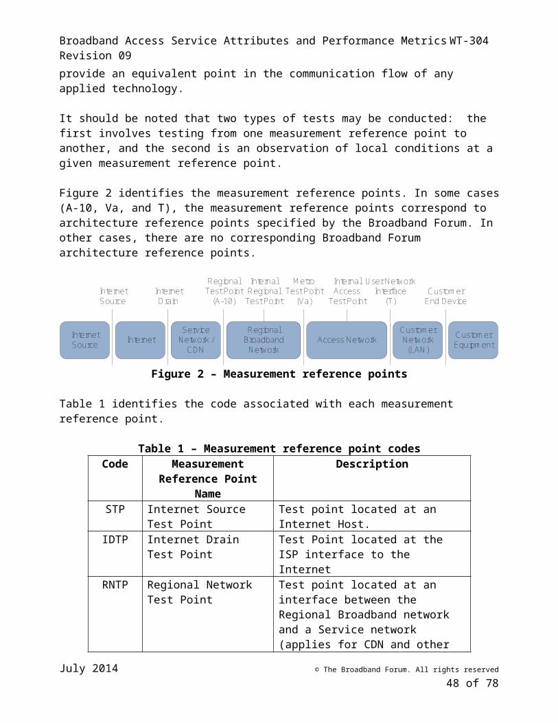
Broadband Access Service Attributes and Performance Metrics WT-304 Revision 09
External Network
Customer Premises Network
Access Provider NetworkData
CollectorMeasurement
Controller
Measurement
RG
WT-304 Agent 1
Measurement function
Netwk Element
WT-304 Agent 2
Measurement function
Mgmt Server (TR-069 ACS)
Mgmt Server (EMS)
Figure 4 – UNI to Internet Drain, use case 2
I.2 Home Network (UNI to CE)Figure 5 shows a use case designed to test performance across a customer premises network. In this scenario, a Measurement Agent within a residential gateway performs measurements with a Measurement Agent installed within a laptop or other device within the home network. The second Measurement Agent may be provided as a device feature (such as an agent within a set-top box or a wireless access point) or it may be a software application installed on a laptop, tablet or other device.
In this use case, the home network agent may not need associations with either a Data Collector or a Measurement Controller. The RG Measurement Agent is generally associated with both functions and handles in-home test scheduling as well as collection of results.
External Network
Customer Premises Network
Access Provider NetworkData
CollectorMeasurement
Controller
RG
WT-304 Agent 1
Measurement function
Laptop
WT-304 Agent 2
Measurement function
Mgmt Server (TR-069 ACS)
Figure 5 – Home network use case
I.3 Business Premises NetworkThe Business Premises use case is structurally similar to the residential Use Case described above. In this case there may be multiple managed and/or unmanaged Measurement Agents within the business subscriber’s network performing measurements with an Agent within a business gateway, as well as potentially directly with each other. Data collection may be handled through the business gateway for measurements involving that endpoint, or through other Measurement Agents for direct in-network measurements.
I.4 Access to Source
July 2014 © The Broadband Forum. All rights reserved
48 of 55
Broadband Access Service Attributes and Performance Metrics WT-304 Revision 09
In Figure 6, measurements are conducted between the UNI and a Measurement Agent located outside of the Access Provider’s network. The external Measurement Agent may be located within another Access Provider’s network, or it may be at a more central location, including immediately on the other side of the A10 interface.
This use case highlights a requirement for an inter-network interface that allows the Measurement Controllers in one network to learn the capabilities and loading conditions present in external Measurement Agents that are made available to it from an external network. The inter-network interface would operate between peer Measurement Controllers in their respective networks.
External Network
Customer Premises Network
Access Provider NetworkData
CollectorMeasurement
Controller
Measurement
RG
WT-304 Agent 1
Measurement function
Ext Element
WT-304 Agent 2
Measurement function
Mgmt Server (TR-069 ACS)
Measurement Controller
Inter-network intf.
Figure 6 – External network use case 1
If there is no such inter-network interface present, the scenario of Figure 6 reverts to that of Figure 7. In this case the external Measurement Method roles may or may not be contained within a WT-304 Measurement Agent. This scenario relies on some non-WT-304 means for learning the capabilities and loading conditions in the external Measurement Method role.
External Network
Customer Premises Network
Access Provider NetworkData
CollectorMeasurement
Controller
Measurement
RG
WT-304 Agent 1
Measurement function
Ext Element
Measurement function
Mgmt Server (TR-069 ACS)
Figure 7 – External network use case 2
I.5 Access to Intermediate Point (UNI to CDN, Middle mile point, other …)The use cases in Figure 2 and Figure 3 are not limited to testing the full path across the access and aggregation networks to the Internet Drain. The second Measurement Agent can be located at other A10 interfaces such as a CDN interface, or at internal interfaces such as Va.
I.6 End to End
July 2014 © The Broadband Forum. All rights reserved
49 of 55
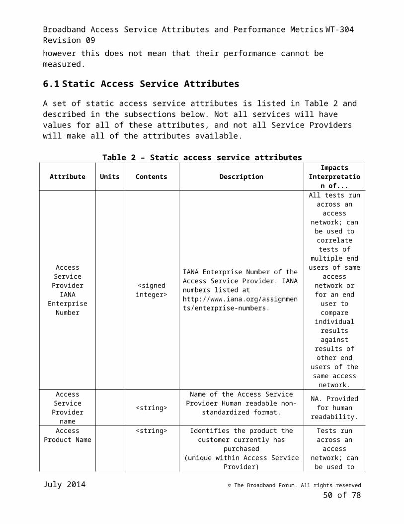
Broadband Access Service Attributes and Performance Metrics WT-304 Revision 09
I.7 Internet Drain to Web ServerBy replacing the RG Measurement Agent of Figure 6 with an agent located on the Access Provider network’s side of A10, the Access Provider can isolate performance issues between internal and external network segments. This scenario is shown in Figure 8.
External Network
Customer Premises Network
Access Provider NetworkData
CollectorMeasurement
Controller
Measurement
Ntwk element
WT-304 Agent 1
Measurement function
Ext Element
WT-304 Agent 2
Measurement function
Mgmt Server (EMS)
Measurement Controller
Inter-network intf.
Figure 8 – External network use case 3
I.8 Internet Drain to Internet Drain
July 2014 © The Broadband Forum. All rights reserved
50 of 55
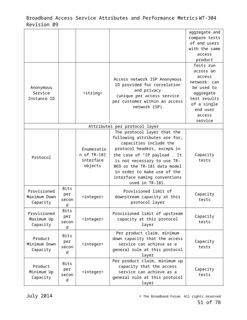
Broadband Access Service Attributes and Performance Metrics WT-304 Revision 09
Appendix II. Post-processing of Measurement Results
II.1 IntroductionMany of the issues related to performance measurements are due to incorrect analysis and characterization of the results. There are many instances where measurement results are said to have certain meaning, where such a meaning cannot be derived from the results with a reasonable degree of certainty. This does not mean that the measurement results were inaccurate or imprecise, or that the wrong measurements were performed – merely that the characterization and presentation of the results and the conclusions drawn had considerable errors.
This section describes methods for proper analysis and characterization of measurement results. Of particular concern, is analysis or characterization intended to be made public and used as a basis of comparison across service providers, as a determination of when a service provider should be punished, or for the shaming and blaming of service providers.
II.2 Minimizing and Quantifying UncertaintyAccording to RFC 2330 [18], “Even the very best measurement methodologies for the very most well behaved metrics will exhibit errors. Those who develop such measurement methodologies, however, should strive to:
• minimize their uncertainties/errors,• understand and document the sources of uncertainty/error, and• quantify the amounts of uncertainty/error.”
Uncertainty is anything that contributes to inaccuracy or imprecision. Uncertainties can be systematic (creating consistent inaccuracy) or random.
When measurement results are used to create derived results and draw conclusions, additional uncertainties may exist, which did not necessarily apply to the raw measurement results. These, too, can be systematic or random.
The recommendations in the following sections are intended to provide information that will allow uncertainty to be minimized and quantified (as best as possible).
II.2.1 Statistical MetricsMany metrics are statistical in nature. That is, they are calculated from raw measurement results. Examples of such metrics include IP Service Unavailability (percentage of total scheduled service time that is categorized as unavailable based on packet or frame loss), and packet loss ratio (the ratio of total lost packets to total transmitted packets in a population of interest).
In order for users of the measurement to consider factors that can impact accuracy and precision, the MA that calculates and reports statistical metrics should report raw measurements (and related information, as described in Section 6) used to calculate the statistical metric.
July 2014 © The Broadband Forum. All rights reserved
51 of 55
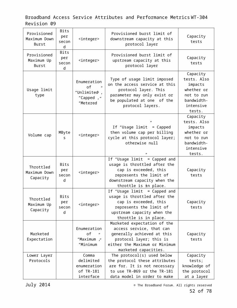
Broadband Access Service Attributes and Performance Metrics WT-304 Revision 09
In addition, it is recommended that openly published statistics include an indication as to how the statistics were calculated. This needs to be sufficiently unambiguous so that others can calculate the same statistic, given the same raw measurements.
These strategies also allow for independent calculation of standard deviations and other measures of uncertainty.
II.2.2 Derived Measurement ResultsStatistical metrics are a form of derived measurements that can be both precise and accurate, when calculated from precise and accurate raw measurements. There exist, however, other forms of derived measurements that can introduce significant uncertainty. An example of a non-statistical derived measurement that can be inaccurate is shown in Figure 9. This example shows measurements that are taken for an end-to-end path and attributed to Segment 2. This assumes that the contributions of Segments 1, 3, and 4 are known and are constant (systematic uncertainty). Where the end-to-end path measurements are constant, the assumption that the Segment 1, 3 and 4 contributions are constant is reasonable, making it reasonable to assume that the Segment 2 performance is constant. Where the end-to-end path measurements vary, it cannot be assumed that all variation is due to Segment 2. The assumption that Segments 1, 3 and 4 are constant in this case should not be made. Taking separate measurements of Segments 1 - 4 after an end-to-end path measurement indicates a problem may not identify which segment caused the variation during the first test, as conditions cannot be assumed to remain the same over time.
Figure 9 – Deriving Single Segment Performance from End-to-end Path Performance
For troubleshooting a problem it is a reasonable approach to use end-to-end measurements to identify when a problem exists, and individual segment testing to isolate the problem. Where the measurements may be used to take punitive action against the Segment 2 ISP, or to publicly assign a performance issue to Segment 2, these sorts of derived metrics are not recommended.
It is recommended that end-to-end path measurements not be attributed to a single segment in the path. Rather, they should be attributed to the end-to-end path, and to all networks in that path.
Where derived measurements are openly published, is important that they not be misrepresented as if they were direct or raw measurements. It is important to note that they are derived, and to provide the measurement data used to derive them.
July 2014 © The Broadband Forum. All rights reserved
52 of 55
ISP Other
networksTest Server
Home network
/ Wifi
End-to-end Path
Segment 4 Segment 2Segment 3 Segment 1
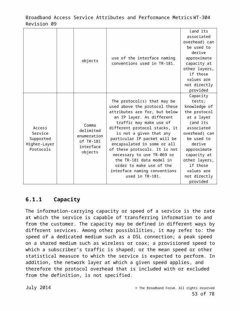
Broadband Access Service Attributes and Performance Metrics WT-304 Revision 09
It is also recommended that users of such derived measurement results be informed of all factors that can cause the results to be inaccurate and/or imprecise (such as the environmental information described in Sections 6.2 through 6.4). The environmental information that is important will vary, depending on the nature of the derived measurement.
For example, when considering the derived measurement of Figure 9, it would be important to let users know:
• Extra segments were traversed• Known performance of extra segments, and how / when this performance was determined • Whether there are congestion or other traffic management rules in place that would cause
traffic between different endpoints to be treated differently• Etc.
As with statistical measurements, the MA should report all raw measurements (and related information, as described in Section 6) used to calculate any derived metric.
II.2.3 Reporting of Test Environment, Conditions, and ParametersIt is recommended that raw measurement results be reported with as much information as possible relating to the conditions under which they are conducted. In addition to any applicable and known service and path-related attributes (Section 6), relevant test information that needs to be reported includes (but is not limited to):
• Time the measurement was run• Networks nodes traversed (including indication of network node operator)• Network links traversed (including indication of network link operator)• Test endpoint information (including equipment or device manufacturer, make, model, and
operating system)• Unambiguous identification of what measurement test was conducted• Test parameters
Of particular interest when running bandwidth measurement tests is knowing:• The amount of other traffic going in and out of the same interface the MA is testing across,
during testing• For access service tests, the amount of traffic going in and out of the WAN access interface
during testing.
It is also recommended that bandwidth tests not be run if there is a significant amount of traffic across the WAN interface immediately prior to starting the bandwidth test.
Where the MA is not collocated in the device with the WAN interface, it can be difficult to get information regarding traffic across the WAN interface. Additional mechanisms are needed to enable this. Such mechanisms are outside the scope of WT-304.
II.3 Comparisons with Provisioned Service Attributes
July 2014 © The Broadband Forum. All rights reserved
53 of 55
Broadband Access Service Attributes and Performance Metrics WT-304 Revision 09
Different broadband services often use different physical layer (e.g., DSL, DOCSIS) and link layer (e.g., Ethernet, ATM) technologies that can make it difficult to compare performance across them.
For example, due to ATM’s use of 52 byte packets, IP throughput of small IP packets can vary greatly depending on the number of ATM packets the IP packet requires. Another cause of variation is DSL’s sensitivity to loop length (the length of the loop will impact the maximum throughput a customer can achieve). Where the IP packets used for measurement differ from the IP packets normally generated by an end user, IP measurements may not accurately reflect the throughput experienced by the end user.
Where service attributes are provided at a different protocol layer than the one where measurements are made, it is important to know this and to account for the additional protocol overhead prior to doing any comparison.
Where a customer’s link is capable of achieving more than the marketed expectation, a provider may choose to overprovision the link so that the marketed expectation is exceeded under certain conditions. When over-achieving measurements are averaged with under-achieving measurements, they may mask the existence of under-achieving measurements.
Where a user’s usage may be throttled after a certain usage threshold is reached, it is important to know this, so that performance is compared correctly to either the pre- or post-throttled allowed bandwidth.
Some access services may specify a minimum and maximum bandwidth range, where the actual achieved bandwidth is dependent on loop length or noise. For an individual user, it can be useful to compare their measured bandwidth against the minimum and maximum achievable. Averaging the measured bandwidth of users who cannot achieve the maximum together with users who can achieve the maximum is not a useful metric, however. More useful would be to know whether all users can achieve the minimum, and the number of users that fall in various bandwidth ranges across the minimum to maximum spectrum. It would also be useful to know, for those that can achieve the maximum, the average bandwidth over time (to see if and how much it varies during periods of network congestion).
II.4 Comparing Measurement Results with Other Measurement ResultsThere is a strong trend in the industry to compare measurement results that take different paths, are collected using different tests, have different endpoints, or are collected at different times.
Comparisons that involve changing a single variable are valuable and can provide useful information. Examples of such comparisons include
• Comparing results from a particular end user, where test endpoints are the same, tests are the same, and only the time of testing is varied; this provides a good understanding of how that end user’s performance changes over time.
Comparisons where multiple variables have changed may be of limited value, as it may be difficult to identify which variable is responsible for the difference between the measurement results. Examples of such a comparison would be:
July 2014 © The Broadband Forum. All rights reserved
54 of 55
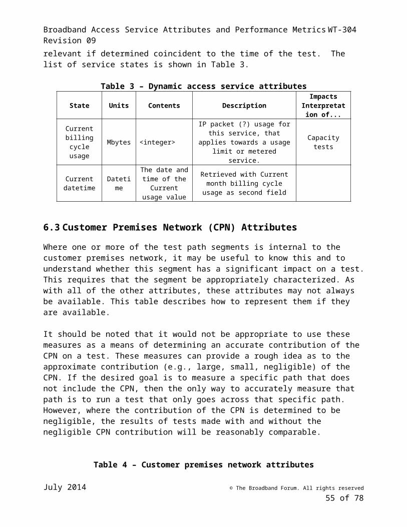
Broadband Access Service Attributes and Performance Metrics WT-304 Revision 09
• Comparing results from 2 geographically distinct end users who are connected to different providers, using different tests, to different test endpoints; this comparison provides no useful information.
Comparing service attribute bandwidths to measured bandwidth of users who are able to achieve the service attribute bandwidth against those who cannot achieve the maximum service attribute bandwidth due to line conditions on their dedicated access loop is not a very useful comparison. Some useful comparisons are:
• The percent of time that users’ measured bandwidth was below their maximum measured bandwidth, with users grouped according to their subscribed access service.
• The percentage of users of an access service who are able to attain the maximum service attribute bandwidth,
• The percentage of users of an access service who are able to attain the minimum service attribute bandwidth.
• The percentage of time that users of an access service had measured bandwidth below minimum service attribute bandwidth.
• The percentage of users of an access service who experience measured bandwidth below minimum service attribute bandwidth more than 0.1% of the time.
End of Broadband Forum Working Text WT-304
July 2014 © The Broadband Forum. All rights reserved
55 of 55