BRITTLE MATERIALS DESIGN, HIGH TEMPERATl!RE GAS …
56
AMMRC CTR76-32 VOLUME II I BRITTLEMATERIALS DESIGN,HIGHTEMPERATl!RE GAS TURBINE ROTOR BLADE DEVELOPMENT AND TURBINE MODIFICATION Technical Report By: Donald G. Miller, Westinghouse Electric Corp., Pittsburgh, PA., 15235 Wayne Van Buren, Westinghouse Electric Corp.,, Pittsburgh, PA., 15235 Raymond J. Bratton, Westinghouse Electric Corp., Pittsburgh, PA., 15235 December, 1976 Final Report Contract Number DAAG 46-71-C-0162 Sponsored by the Advanced Research Projects Agency ARPA Order Number 1849 Project Code Number lDl0 Agency Accession Number DA OD 4733 Approved for public release; distribution unlimited. Prepared for ARMY MATERIALS AND MECHANICS RESEARCH CENTER Watertown, Massachusetts 02172
Transcript of BRITTLE MATERIALS DESIGN, HIGH TEMPERATl!RE GAS …

AMMRC CTR 76-32 VOLUME II I
BRITTLE MATERIALS DESIGN, HIGH TEMPERATl!RE GAS TURBINE ROTOR BLADE DEVELOPMENT AND TURBINE MODIFICATION
Technical Report By:
Donald G. Miller, Westinghouse Electric Corp., Pittsburgh, PA., 15235 Wayne Van Buren, Westinghouse Electric Corp.,, Pittsburgh, PA., 15235
Raymond J. Bratton, Westinghouse Electric Corp., Pittsburgh, PA., 15235
December, 1976
Final Report
Contract Number DAAG 46-71-C-0162
Sponsored by the Advanced Research Projects Agency
ARPA Order Number 1849
Project Code Number lDl0 Agency Accession Number DA OD 4733 Approved for public release; distribution unlimited.
Prepared for
ARMY MATERIALS AND MECHANICS RESEARCH CENTER Watertown, Massachusetts 02172

The findings in this report are not to be construed as an official Advanced Research Projects Agency, Department of the Army, or U.S. Government position, either expressed or implied, unless so designated by other authorized documents.
Mention of any trade names or manufacturers in this report shall not be construed as advertising nor as an official indorsement or approval of such products or companies by the United States Government.
DISPOSITION INSTRUCTIONS
Destroy this report when it is no longer needed. Do not return it to the originator.

AMMRC CTR 76-32 Volume III
BRITTLE MATERIALS DESIGN, HIGH TEMPERATURE GAS TURBINE ROTOR BLADE DEVELOPMENT AND TURBINE MODIFICATION
Technical Report By:
Donald G. Miller, Westinghouse Electric Corp., Pittsburgh, PA., 15235 Wayne Van Buren, Westinghouse Electric Corp., Pittsburgh, PA 15235
Raymond J. Bratton, Westinghouse Electric Corp., Pittsburgh, PA 15235 Program Manager
December, 1976
Final Report
Contract Number DAAG 46-71-C-0162
Sponsored by the Advanced Research Projects Agency
ARPA Order Number 1849
Project Code Number lDl0
Agency Accession Number DA OD 4733
Approved for public release; distribution unlimited.
Prepared for:
ARMY MATERIALS AND MECHANICS RESEARCH CENTER Watertown, Massachusetts 02172

ABSTRACT
Ceramic rotor blade development with performance simulation by computer and a demonstration of ceramic stator vanes operating in an advanced version of a stationary turbine engine were part of the original project objectives which were only partially completed. While a reorgani- zation of program priorities placed emphasis on stator vane design, analysis and static rig testing in lieu of the blade development and turbine demon- stration tasks, the Westinghouse Research 6 Development Laboratories did develop a comprehensive three dimensional finite element computer code (WISEC) for the analysis of complex structures like the turbine blade. DARPA project funds were used for the development of many critical sub- routines contained within WISEC. A family of three dimensional, mixed isoparametric elements evolved for the modeling of a variety of loading conditions in both stress and heat conduction analyses. The code possesses an ability to: (1) Analyze materials with temperature dependent properties; and (2) Handle anisotropic as well as isotropic materials.
When WISEC was used in the analysis of a preliminary ceramic rotor blade design with dovetail root attachment, principal tensile stresses of the order of 26,000 psi were calculated in the root section for steady- state conditions of temperature (2500°F peak turbine inlet) and speed (4850 rpm). The critical root stresses were shown to be sensitive to the surface area of contact, friction coefficient at the attachment interface, and the dovetail root angle between 30 and 60". Stress levels reached 14,000 psi at the base of the airfoil section under centrifugal loading- steady state temperature conditions.
A turbine test rig (W251 stationary gas turbine) with eddy current brake replacing the electrical generator did exist at Westinghouse Power Generation Systems Division when the contract award was made in 1971. The unit was designated for the high temperature test of ceramic stator-vanes. Layout drawings and design specifications for the modification of this test turbine for 2500'F peak temperature operation were completed when the work was suspended and then terminated by a DARPA/AMMRC directive in 1973.
ii

TABLE OF CONTENTS
Section Page
ABSTRACT .......................... ii
LIST OF ILLUSTRATIONS ................... V
LIST OF TABLES ....................... vi
FOREWORD .......................... vii
SUMMARY .......................... ix
SECTION 1 INTRODUCTION .................. 1
SECTION 2 CERAMIC ROTOR BLADE DEVELOPMENT . . . . . . . . . 7
2.1 INTRODUCTION . . . . . . . . . . . . . . . . . . . . . 7 2.2 FINITE ELEMENT PROGRAM . . . . . . . . . . . . . . . . 8 2.3 CERAMIC ROTOR BLADE DESIGN . . . . . . . . . . . . . . 13 2.4 CERAMIC ROTOR BLADE ANALYSIS . . . . . . . . . . . . . 20
SECTION 3 THE ADVANCED TURBINE MODIFICATION . . . . . . . . 29
3.1 INTRODUCTION . . . . . . . . . . , . . . . . . . . . . 29 3.2 THE ROTATING TEST TURBINE . . . . . . . . . . . . . . 31
SECTION 4 CONCLUSIONS . . . . . . . . . . . . . . . . . . . 37
SECTION 5 REFERENCES . . . . . . . . . . . . . . . . . . . . 39
iii


LIST OF ILLUSTRATIONS
Figure
l-1 l-2
The Westinghouse W251 Gas Turbine Iterative Development Procedure for Industrial Gas Turbine Components
l-3 ARPA Stationary Turbine Project-Iterative Development Plan l-4 Stator Vane Development of the Stationary Turbine Project
2-l 2-2 2-3 2-4 2-5 2-6
Isoparametric-Elements for the WISEC Program WISEC Flow Chart 2D Model of Blade Root and Rotor Two Dimensional Finite Element Computer Model Maximum Principal Stress Contours in a 30° Blade Root Effect of Root Angle and Friction on the Maximum Stress
in a Blade Root 2-7 Effect of Friction Coefficient on the Maximum Stress in a
Blade Root 2-8 The Effect of Control Area on the Maximum Stress in
a Blade Root 2-9 2-10 2-11 2-12 2-13 2-14
Hollow Ceramic Rotor Blade A Computer Plot of a Ceramic Rotor Blade Material Orientation for the Orthotropic Analysis Inlet Temperature Profile Film Convection Coefficients for the Ceramic Blade Steady State Temperature (OF) Distribution Across Ceramic
Blade Airfoil 2-15
2-16
2-17 2-18
Steady State Thermal and Centrifugal Radial Stress (psi) Distribution for a Ceramic Rotor Blade
Steady State Thermal and Centrifugal Maximum Principal Stress (psi) Distribution for a Ceramic Rotor Blade
Finite Element Model of Root and Rotor Maximum Principal Stress (psi) Distribution in Blade Root
and Rotor 2-19 Deformation in Blade Root and Rotor
3-l 3-2
3-3 3-4 3-5 3-6
W251 Turbine Test Facility Relative Total Temperature versus Blade Height 251 RR
High Temperature Test (2300OF TIT) Row 2 Blade Cooling Requirements Row 2 Vane Cooling Requirements Cooling Flow Comparisons 1950' and 2300'F (TIT) Subassembly and Assembly Identification for the
W251 Test Turbine Modification
V

LIST OF TABLES
Table 2-l Effect of Critical Design Parameters on Maximum Tensile Stress
Vi

FOREWORD
The Stationary Gas Turbine Project represents the Westinghouse con- tribution to the Defense Advanced Research Project Agency (DARPA) spon- sored "Brittle Material Design, High Temperature Turbine" program, Order Number 1849, Contract Number DAAG-46-71-C-0162.
The final report is presented in four volumes as follows:
Volume I - Program Sumplary
Volume II - Ceramic Stator Vane Development
Volume III - Rotor Blade Development and Turbine Modification
Volume IV - Materials Technology
Final results of static rig testing and analysis for the tenth semi- annual report period are included as part of this final report which represents a comprehensive project review summarizing the activities from July 1, 1971 to June 30, 1976.
Westinghouse performed this work under subcontract to the Ford Motor Company, prime contractor for the Defense Advanced Research Project Agency. The Army Material and Mechanics Research Center (AMMRC) at Watertown Arsenal, Watertown, Massachusetts, served as Program Monitor for DARPA.
The program's overall Principal Investigator was Mr. A. F. McLean, who also served as Program Manager for the Ford Vehicular Turbine Project.
Dr. R. J. Bratton was Principal Investigator and Program Manager for Westinghouse, Mr. D. G. Miller served as Project Engineer. Mr, A. N. Holden, now deceased, functioned as Project Manager at Westinghouse Generation Systems Division from July 1, 1971 to May 1, 1975. Mr, G. Levari succeeded Mr. Holden with Mr. C. R. Booher, Jr, accepting respon- sibility for design, analysis and rig testing for the Division at that time.
Westinghouse wishes to acknowledge the efforts of the following personnel who contributed to the program:
1. Dr. Maurice J. Sinnott who conceived and started the program when he was at DARPA in 1971.
vii

2. DARPA - for support of the program. Dr. E. Van Reuth and Dr. M. Stickley for their interest and support.
3. AMMRC - for monitoring the program. Dr. E, S. Wright, who replaced Dr. A, E. Gorum (presently retired) as Technical Monitor, and Drs. R. N. Katz, E.N. Lenoe and H. Priest.
4. Ford Motor Co, - A. F. McLean, T. W. McLaughlin, E. A. Fisher, P. Berry, R. R, Baker and A. Paluszny.
The final report was prepared and edited by D. G. Miller and R, J. Bratton with editing assistance from E. J. Phillips. Contributions to the final report were made by C. R.Booher, Jr., S. C. Singhal, F. F. Lange, W. Van Buren and E. S, Diaz.
Other Westinghouse and former Westinghouse employees who contributed to the technical program include:
Westinghouse Generation Systems Division
J. Allen, G. W. Bauserman, D. D. Lawthers, L. Kish, F. Laus, S. D. Leshnoff, S. Mumford, T. J. Rahaim, J, D. Roughgarden, S. C. Sanday, R. J. Schaller, C. E. Seglem, E. J. Stenowoj, J. P. Smed, L. C. Szema, S. Twiss, E. H. Wiler, D. D. Wood
Westinghouse R&D Center
D. Boes, W. C. Frazier, R, Kossowsky, S, Y, Lee, C, Visser, J. H. White, W. E. Young, S. Gabrielse, D. E. Harrison
This final report is dedicated to A. N. Holden.
viii

HIGH TEMPERATURE STATIONARY GAS TURBINE CERAMIC ROTOR BLADE DEVELOPMENT AND THE ADVANCED TEST TURBINE
SUMMARY
The "Brittle Materials Design High Temperature Gas Turbine" program was formulated under the auspices of the Defense Advanced Research Projects Agency (DARPA) of the Department of Defense (DOD) to demonstrate the use of brittle material design concepts in the successful application of ceramics as structural components in high temperature gas turbines. The talents of the Ford Motor Company and Westinghouse, as prime and subcontractor, respectively, were directed toward the development of a vehicular ceramic turbine (Ford) and a ceramic stator vane for a large stationary gas turbine (Westinghouse). The Army Materials and Mechanics Research Center (AMMRC) served as technical monitor for DARPA.
Ceramic rotor blade development with performance simulation by computer and a demonstration of ceramic stator vanes operating in an advanced version of a stationary turbine engine are part of the original project objective to be discussed here in Volume III of the "High Temperature Stationary Gas Turbine" final report. While a reorganization of program priorities placed emphasis on stator vane design, analysis, and static rig testing in lieu of the blade development and turbine demonstration tasks, the Westinghouse Research and Development Laboratories did develop a comprehensive three dimensional finite element computer code (WISEC) for the analysis of complex structures like the turbine blade.
DARPA project funds were used for the development of many critical sub-routines contained within WISEC. A family of three dimensional, mixed isoparametric elements evolved for the modeling of a variety of loading conditions in both stress and heat conduction analyses. The code possesses an ability toanalyze structures made of materials with temperature dependent as well as anisotropic properties.
When WISEC was used in the analysis of a preliminary ceramic rotor blade design with dovetail root attachment, principal tensile stresses of the order of 26,000 psi were calculated in the root section for steady-state conditions of temperature (2500°F peak turbine inlet) and speed (4850 rpm). The critical root stresses were shown to be sensitive to the surface area of contact, friction coefficient at the attachment interface, and the dovetail root angle between 30 and 60'. Stress levels reached 14,000 psi at the base of the airfoil section under centrifugal loading-steady state temperature conditions.
ix

A turbine test rig (W251 stationary gas turbine) with eddy current brake replacing the electrical generator did exist at Westinghouse Power Generation Systems Division when the contract award was made in 1971. The unit was designated for the high temperature test of ceramic stator- vanes. Layout drawings and design specifications for the modification of this test turbine for 2500°F peak temperature operation were completed when the work was suspended and then terminated by DARPA/AMMRC decision in 1973.
X

SECTION 1
1. INTRODUCTION
The "Brittle Materials Design High Temperature Gas Turbine" program was formulated under the auspices of the Defense Advanced Research Projects Agency (DARPA) of the Department of Defense (DOD) to demonstrate the use of brittle material design concepts in the successful application of ceramics as structural components in high temperature gas turbines. The talents of the Ford Motor Company and Westinghouse, as prime and sub- contractor, respectively, were directed toward the development of a vehicular ceramic turbine (Ford) and a ceramic stator vane for a large stationary gas turbine (Westinghouse). The Army Materials and Mechanics Research Center (AMMRC) served as technical monitor for DARPA.
The five-year performance period of the Westinghouse Stationary Gas Turbine Project, July 1, 1971 through June 30, 1976, is summarized in Volume I, "The Program Summary" of this report. Volume II is a comprehensive discussion of Ceramic Vane Development organized to include Preliminary Design and Analysis, Three Generations of Ceramic Vane Assembly Design and Analysis, Static Rig Test Results at 2200 and 2500°F, a Ceramic Vane Performance Review and finally Ceramic Stator Vane Fabrication. Here in Volume III, "High Temperature Stationary Gas Turbine-Ceramic Rotor Blade Development and the Advanced Test Turbine," the engineering aspects of three dimensional heat transfer and stress analysis, ceramic rotor blade design and analysis and the advanced turbine design modification are explored in some detail. The three-dimensional finite element stress analysis code (WISEC) was used to analyze a preliminary ceramic rotor blade design with dovetail root attachment. Layout drawing and design specifica- tions for the modification of the test turbine (Figure l-l) were completed.
Figure 1-2 is reproduced from Volume I to emphasize the iterative development of ceramic components for industrial gas turbines as identified in Figure l-3. Component development and material technology follow parallel but interacting paths to provide the coordination for fabrication, static-rig testing and final demonstration in the overall project plan. Failure analysis with design modification, further analysis and material improvement forms the iterative loop required for successful application.
Overall program objectives, as originally proposed and finally accomplished, are illustrated in Figure l-4. Final rotor blade design and computer simulation were delayed, then terminated in 1973 to permit full concentration of effort on the formidable tasks of ceramic vane development and static rig construction. The 30 megawatt turbine demonstration was also delayed and terminated when it became obvious

1 Powrar Twbi
f Exhaust
Figure l-l. Westinghouse W251 Gas Turbine

r---------------------- --_----------__
I I
1 _-----
1 Component - Design & t I
Development Analysis I
I 1
Component Fabrication - Rig - Failure Turbine
8, NDE Tests Anal. - Test
3 Material _ Properties of I
Technology Fabrication 4 A km-- ---_ I I L------------------------------ __________ 1
f Turbine
Field Test
- Interactive
Figure l-2 Iterative Development Procedure for Industrial Gas Turbine Components
that the rapidly escalating costs of an advanced turbine rig conversion and the need for additional verification of stator vane performance in the static rig placed this task beyond a reasonable scope of funding within the designated period of performance (5 years).
Essential elements of the ceramic stator vane development appear in Figure 1-5. The design process with appropriate analysis proceeded logically from the preliminary stages, through Vane Designs I and II to the final third generation, three-piece stator vane assembly with tapered-twisted airfoil. Component fabrication had to follow a parallel rather than a subsequent or series route in many cases, anticipating the design because of the long lead time required to meet the static rig test specifications as scheduled. Fabrication processes were developed as part of component manufacture, thus complicating the procedure. The second generation airfoil, for example, was committed to initial procurement before analysis disproved design viability. The static rig test facility planned as a simple modification of an existing rig, became a dynamic development activity coincident with the design and fabrication tasks. Indeed, the static rig requirement to test at 2500'F became the critical element in the project plan. Only once, in the final phases when the component supplier failed to deliver acceptable third generation hardware on time, was a critical delay experienced for a reason other than static rig availability.
Although the total effort was directed toward higher service temperatures to increase power and efficiency, no attempt was made to achieve specific levels of improved performance in either the static rig tests or an actual test turbine. The test cycle sequence, i.e., 100 cycles of peak load service at a maximum inlet temperature of 2500°F in a controlled shutdown mode, was selected to establish realistic boundary conditions for the demonstration of first stage stator vanes using the best commercial materials available. The boundary conditions thus established also served as a design constraint in the development of rotor blades as well as the stator vane components.
3

k
M I

. I Blade 3-D Analysis I Blade
3-D Analysis * m _ ---s-B+ --
c Development Preliminary Blade Design
I Design & I Computer
/ I I Simulation ,
J- I I I
J
t I I L
1 1 . Engineering Properties
Material Technology - I
4 Materials Science - - - -- Orginal Objectives
1 - Revised Objectives
c----) Interactive Tasks NDE
I I
-------- 1
30 MW Test ; Turbine I
Demonstration l 25OO’F
I _------ 1
Figure l-4 ARPA Stationary Turbine Project-Iterative Development Plan

Component Development
Process
Design
Fabrication
NDE
Testing
Failure Analysis
July lY71 0
Time (Years) -
July 1972 July 1973 July 1974 July 1975 July 1976 1 2 3 4 5
Kinematic Model
I I
Design - Vane Design 1 - Va
& Assembly
Design Sketch
NDE _ NDE L NDE Vane 1 Vane 1 Vane 3
1 _
1 t 1
- I-
New Rig Design &
- I Construction
Test Cycle Defined
To 2nd Iteration e Design/Fab. /Testing
Vane 3, 25W’F
Legend
m Major Decision Points
0 Major Milestones
X Discontinue l2.3 - Vane Design Iteration
r---25000;---; I i Turbine I
’ Demonstration -I I i Cancelled i I L---------J
Figure l-5 Stator Vane Development Stationary Turbine Project
6

SECTION 2
2. CERAMIC ROTOR BLADE DEVELOPMENT
2.1 INTRODUCTION
Due to the complex, three-dimensional geometry of ceramic turbine blades, it was not possible to perform a structural analysis by classical analytical methods. Therefore, a numerical analysis or experimental method was used as required to obtain the desired stress distribution in the blades. Among the several numerical methods which have been developed, the finite element method was chosen.
The term finite element denotes the type of idealization used to reduce the continuous structure to a system of discrete bodies. In this method the structure to be studied is divided into a finite number of subregions, called finite elements, which are interconnected at certain points, called nodal points. For stress analysis problems the dis- placements of these nodal points are the basic unknown quantities, while for heat conduction analyses the unknown terms are the nodal point temperatures.
In order to meet the requirements of ceramic rotor blade analysis, several features were developed for implementation into a finite element computer code. These features included:
1. A family of three-dimensional mixed isoparametric elements.
2. A variety of loading conditions for both the stress analysis and the heat conduction elements.
3. The ability to analyze materials with temperature dependent properties.
4. The ability to model isotropic or anisotropic materials.
The analysis of ceramic rotor blades is discussed by first giving a summary of the development work required to obtain the necessary tools for the analysis. A description of the finite element model chosen for the analysis and a discussion of the results for the case of combined thermal and centrifugal loading of ceramic rotor blading are also given.

2.2 FINITE ELEMENT PROGRAM
The use of a three-dimensional isoparametric element (2) permits the number of nodes on the sides of the element to be varied. Variable strain capability also exists in this high order element. The total capability, therefore, facilitates the generation of graduated element networks and also makes it possible to model curved boundaries.
Four different types of elements (Figure 2-l) have been incorporated into the Westinghouse Isoparametric Finite Element Computer Code (WISEC). They are:
1. Eight-node element (linear displacements);
2. Twenty-node element (quadratic displacements);
3. Thirty-two-node element (cubic displacements);
4. Mixed element.
The mixed element is the most versatile because it allows the users to vary the number of nodes. It also facilitates the generation of graduated element networks to properly account for regions where large stress gradients are anticipated. These regions can be modeled with 20- or 32-node elements while other areas away from high stress gradients need only be modeled by 8-node elements.
LINEAR ELEMENT 18 NODES) QUADRATIC ELEMENT (20 NODES)
CU BIC ELEMENT 02 NODES)
Figure 2-1 Isoparametric Elements for the WISEC Program
8
The elements described above have been derived for both the heat conduction analysis and the stress analysis. (2) This means that an identical finite element model can be used for both the heat conduction and the stress analysis.
In order to analyze a variety of heat conduction problems, the following boundary conditions and thermal loads can be handled by the program:
1. Prescribed temperature at any node;
2. Prescribed heat flux;
3. Heat generation;
4. Forced (linear) convection;
5. Natural (non- linear) convection;
6. Radiation.
The heat conduction analysis can be either steady-state or transient. In a transient case any of the thermal loads or boundary conditions can be considered as time-dependent quantities. The resulting temperature, either the steady-state or transient values, can be stored in an output file for futher use in a stress analysis calculation or for graphical display by a plotting device. (4) A data transfer capability makes this feature possible.
The thermal material properties can be isotropic or anisotropic. In addition to prescribing the temperature at any nodal point, other temperature constraints can be modeled. Groups of nodes having equal but unknown temperatures are permissible in the analysis. It is also possible to relate nodal temperatures by a general constraint equation. These are not used in the ceramic rotor blade analysis, but the feature has been incorporated into the program.
The stress analysis portion of the finite element computer code can solve problems involving general types of materials under a variety of loadings and boundary conditions. The code has anisotropic as well as isotropic material properties
thih;; R
acity to use
either temperature independent or temperature dependent. (3) may be
If they are sensitive to temperature, the material properties represent input to the program in tabular form.
The following types of displacement boundary conditions have been incorporated into the program. (3)
1. Prescribed displacements.
2. Groups of nodal points having equal but unknown displacements in a given coordinate direction.
3. Displacements restricted to a prescribed direction.
4. General linear constraint displacement.
9

Displacement boundary condition 4 is the most general that can be handled with a linear system of equations. The first three boundary conditions may be considered as special cases of the fourth.
Loading cases which are considered by the program,include:
t : Static uniform pressures. Surface tractions.
C. Centrifugal force loads d. Thermal loads e. Gravitational body forces.
Centrifugal loads are represented as nonuniform pressures, uniform and nonuniform shearing forces, and as concentrated point loads.
The output from a stress analysis run, namely the nodal point displacements, stresses and principal stresses and directions, may be stored in an output file for use in a post-processor program which has the capability of producing contour plots of any of the output data. The accuracy of the program has been verified on a number of problems for which known solutions exist.(3) These problems are of a simple nature compared to practical design problems, since no exact solutions for complicated geometries are known.
An efficient equation solver is required because of a finite element formulation of complex three-dimensional structures may involve a system of linear equations having several thousand unknowns. The computer code employs an equation solver based on a Gaussian elimination method which uses a wave-front technique. With this technique the formation and solution of the finite element equations are interconnected. This method can solve large systems of equations, provided that the wave front does not exceed certain limits which depend on the configuration of the computer system used.
Pre- and post-processors exist in the form of several auxiliary computer programs which were developed to aid in the preparation of input data for the heat conduction and stress analysis programs and to plot selected results of the programs. One such pre-processor allows the analyst to produce computer plots of the collection of finite elements or mesh used to model the structure. This provides for an error check of input and for mesh refinement as required.
A post-processor was used a heat conduction analysis on from a stress analysisJ4)
to produce contour plots of temperatures from any of the various stress components obtained
10

The contents of the WISEC program manual are summarized below:
Introduction The Isoparametric Elements - 3D with Material Axis Orientation* Finite Element Theory - Electric Stress Analysis
Stiffness Matrices The Mass Matrix The Element Load Vector Due to Traction, Body Forces,
Centrifugal Forces and Temperature The Wave Front Equation Solver - Gaussian Elimination and
Frontal Bookkeeping *Displacement Boundary Conditions *Elastic 3D Stress Analysis-Input/Output Examples of Elastic Analysis with WISEC
Rectangular Bar in Uniaxial Compression Rectangular Bar Subjected to a Moment at One End Cantilevered Rectangular Bar Loaded with A Concentrated
Load at the End Thick Walled Cylinder Subjected to Internal Pressure
and Centrifugal Loading Analysis of a Ceramic Rotating Turbine Blade
Appendix A-Preliminary Set Up for Geometry Plots
Three dimensional thermal and/or stress analysis using WISEC is illustrated by the flow chart in Figure 2-2. Analyses can be performed by Westinghouse on a contract basis. The code itself has been made available to AMMRC in the form of a 'IWISEC Users Manual." While WISEC specifically, was not used foranalyses done thus far on Department of Energy Contracts E-49-18-2290 and EF-77-C-01-2786, the "High Temperature Gas Turbine," and "Ceramic Technology Development" programs respectively, it was the basis for WECAN, the finite element stress analysis code superceding WISEC, which was. The Electric Power Research Institute (EPRI) Ceramic Rotor Blade Development contract RP 421-l utilized both WISEC and its successor WECAN for the stress analysis of blade root forms under boundary conditions of centrifugal loading at room temperature.
Elements of WISEC developed solely or partially with DARPA funds.
11

- Problem
Definition
I
L Nitter -4 (Sub-Steps)
I r I
Nodal Temperatures
Nsteps
(Time)
Transient Heat Conduction
Problem Definition
I
Geometry Definition
I * Material
Properties
I
Bou dar Condkon !
I Read in Temp.
- Tape for a Thermal Stress Analysis
I Stiffness Matrices
and Load Vectors
1 I Displacements
I
Stresses
I
Generate Plot Generate Plot Tape if registered Tape if registered
1
J ReadinPlotTape )
I Read in Plotting Command cards
5 3 I
I 1 Read in Plot Tape
. I
Plot
I I I
0 End 0 0 End End
Static Elastic Analysis Static Elastic Analysis Post Processor Post Processor
Figure 2-2 WISEC Flow Chart
12

2.3 CERAMIC ROTOR BLADE DESIGN
As was the case with the ceramic stator vane design, the ceramic rotor blade design study was performed with reference to the Westinghouse W251, 30 megawatt frame-size stationary gas turbine. The preliminary design concept was that of the final stage W251 rotor blade with dovetail root substituted for the more conventional fir-tree design. The airfoil and platform were not modified because they represented optimized elements of an integral blade based upon aerodynamic principles and accepted procedures to minimize leakage from the gas path, respectively. In a finalized design, the airfoil and platform would be scaled with respect to a chord parameter to meet the constraint of a fixed chord to pitch ratio in the optimization of thermal stress distribution. The dovetail root attachment was preferred in all cermet and earlier ceramic blade design and development studies. Its selection was based upon prior art. (15)
In order to optimize the root cross-sectional geometry, a state of generalized plain strain was assumed to exist in the root.(4) This allowed the two-dimensional plain strain model shown in Figure 2-3, to be used. The centrifugal force, Fc, as shown in the figure, is resisted by normal and shear forces, F, and Fs, whose respective stresses act uniformly over the contact area, A,, with conditions of symmetry along the center- line of the root. The disc that holds the root is considered rigid in in this model and the shear stress developed is assumed to be the maximum attainable for the given root geometry.
Q Root
Figure 2-3 2-D Model of Blade Root and Rotor
13

With these assumptions, the effects of several parameters on the stresses induced by F, were analyzed, namely the included angle, a , the area of contact A,, and the friction coefficient, 1-(. This parametric study was accomplished using finite element models with the objective of minimizing the root stress. For purposes of analysis, the blade roots were subjected analytically to the force F, resulting from a rotational speed of 4850 rpm, the design speed of the W251.
Figure 2-4 is representative of the finite element models used to examine the effect of the included angle,a , when it is made equal to 30°, 45' and 60'. The finite element mesh for these models consisted of constant strain triangles. The results of the first parametric study in
2 which the friction coefficient, u = 0, and area of contact AC = 0.675 in. , based on a root length of 4.1 in., are shown in Figure 2-5. A maximum stress of 24,000 psi occurred in the fillet radius of the root.(4) This result was expected based on stress concentration and notch sensitivity data reported in the literature.(8-13)
Figure 2-4 Two Dimensional Finite Element Computer Model for a 30' Root
14

When the study was extended by introducing a shear stress on the contact area, A,, a marked effect on the root stress was obtained.C4) This shear stress, as calculated from Coulomb's Law (Fs >= 1-I Fn> 9 was distributed uniformly over the contact area. Furthermore, F, was assumed equal to IJ F, where 1-1 is taken as the angle of static friction, p= tan (90' - a). Where a- 30°, the friction coefficient, p = 1.73, gives the maximum obtainable shear stress that can develop on the contact area of the root. The result of this particular analysis is shown in Figure 2-Salso. The effect of friction on the contact area is to increase the maximum tensile stress and shift it from the fillet radius to a point slightly above the contact area. This phenomenon was not predictedby pull tests (8)
or stress concentration studies.(l3) For the root geometry described above, the maximum stress increases from 24 to 38 ksi as the coefficient of friction increases from 0 to 1.73. Thus, friction has a pronounced effect not only on the magnitude but also on the distribution of maximum stress in the root.(4) The average stress across the neck of the root which offsets the centrifugal force on the blade, is 11 ksi for both cases of p = 0 and 1.73.
No.
1 2 3 4 5 6 1 8 9
10 11 12 13 14 15
Stress
-15Wl
No. Stress
-16ooo -1m
1 -1COO ml
: 5ax
-loo00 -7m.l -4LXl - loo0
E m
4 8m 5 llcm 6 14ooo 1 17cw 8 20000 9 2m
llcal 14Wl
10 2mo 11 nxm 12 3mm
17cm 20000 2ml
No shear, p= 0 With shear, lJ = 1.73
Figure 2-5 Maximum Principal Stress Contours in a 30" Blade Root
15

The foregoing analysis was repeated on 30°, 45' and 60° roots for a contact area of 1.35 in.2 based on the root length of 4.1 inches.(4) The results are plotted in terms of the maximum tensile stress as a function of angle, a, for the case with and without friction in Figure 2-6. The values of 1-1 for the root angles of 45' and 60°, were 1.0 and 0.58, respectively. Friction causes higher stresses in the root as observed from Figure 2-6. The maximum tensile stress occurred slightly above the contact area for the root if there was friction, but it shifted back to the fillet radius of the root when friction was eliminated. Increasing the angle+, when friction was present, had little effect on the maximum tensile stress in the root (Figure 2-5). This was due to the fact that as a increased,the angle of static friction, tan (90"-a ), decreased, hence p was reduced. A reduction in 1-1 had the effect of keeping the maximum tensile stress fairly constant as a varied from 30° to 60°. Elimination of friction resulted in lower maximum stresses in the root for the cases studied. The largest reduction in stress occurred for a root angle of 30°. For this case, eliminating friction resulted in a 45% drop in stress. Furthermore, the maximum tensile stress followed the value of the theoretical stress concentration of the root when friction was not present. The concentration factor for the 60' root was slightly smaller than the factor for the 4S" root, 1.25 compared to 1.27. This accounted for a slightly higher stress in the 45" root for the frictionless case.
3 I
lJ=o // /---------_-- / / / 25 ,/
20 I I 1 I I I 30 35 40 45 50 55 60
Root Angle, a o
Figure 2-6 Effect of Root Angle and Friction on the Maximum Stress in a Blade Root
16

TO better understand the role of friction in root design with brittle materials the coefficient of friction on a 30° root with a contact area of 1.35 in.2 was varied from 0 to 1.73.(4) The maximum root stress associated with this range of friction coefficients is shown in Figure 2-7. The stress varied nonlinearly with p. A higher rate of increase in stress occurred at lower values of lo 0 < p < 1.0. Since the stress increased from 23.4 ksi to 33.8 ksi as P varied from 0 to 1.73, for example, there was an obvious benefit from reducing the coefficient of friction between the ceramic blade and metal disc. The use of a low friction material at this interface is recommended strongly.
1 I
0. 5 1. 0 1. 5 Coefficient of Friction, v
Figure 2-7 Effect of Friction Coefficient on the Maximum Stress in a Blade Root
The effect of contact area on root stress was the last design parameter studied.{41 A contact area of 1.35 in.2 was used to determine the effect of friction and root angle on the maximum tensile stress. In general, the contact area can vary from the design area on the maximum tensile root stress, for a range of 0.25<Ac L 1.35 in.2, is given in Figure 2-8 for a 30' root, with p = 1.73. Decreasing the contact area increases the maximum tensile stress in the root. For example, lowering the contact area from 1.35 to 0.25 in.2 raised the maximum tensile stress from 33.8 ksi to 40.6 ksi, i.e., an increase of 20%.
17

!3l I I I I I
(I= XY
u = 1.73
I xl I I I I
0 .25 .5 .75 1.0 1. 25 1. 5 Contact Area, Ac In2
Figure 2-8 The Effect of Contact Area on the Maximum Stress in a Blade Root
The maximum stress in a rotating blade can be reduced by 30% if hollow geometry is used. This concept is illustrated in Figure 2-9. The use of a hollow airfoil has the effect of reducing the mas of the blade, and therefore, the centrifugal force acting on the root. (47
Figure 2-9 Hollow Ceramic Rotor Blade
18
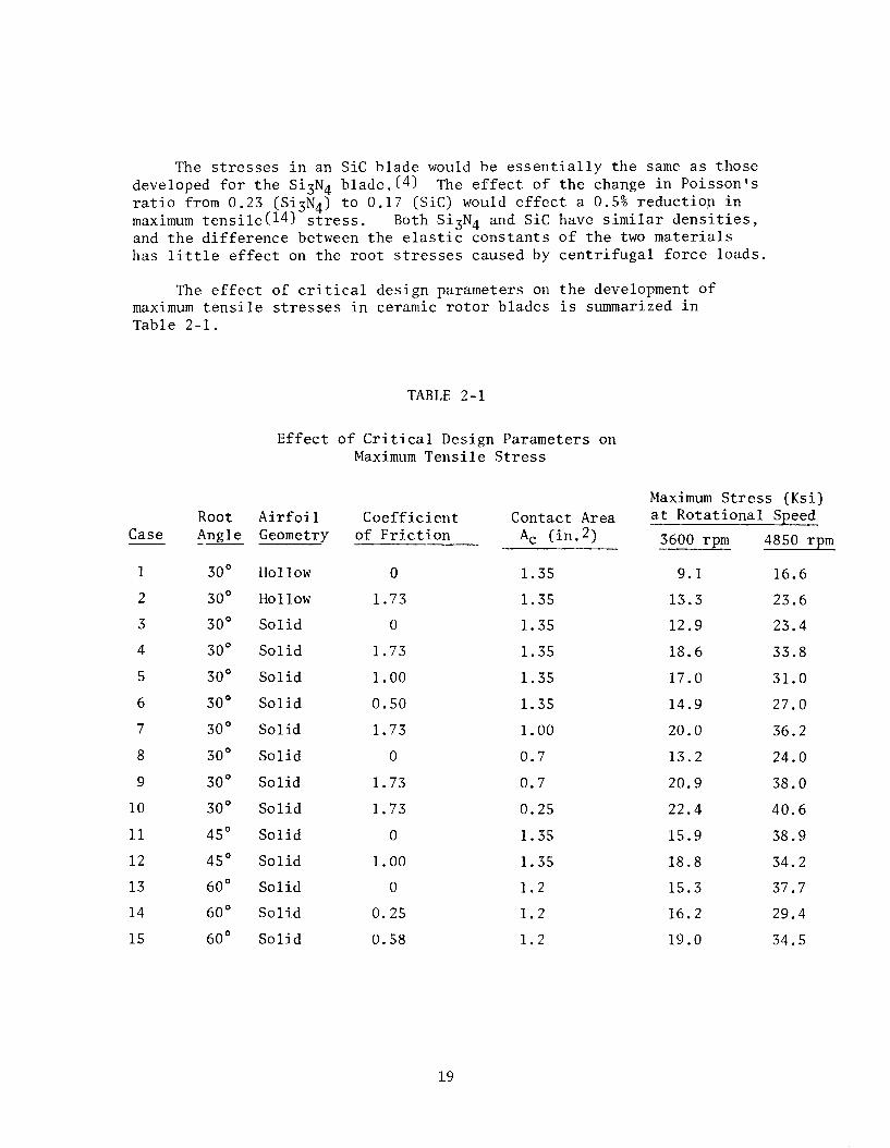
The stresses in an Sic blade would be essentially the same as those developed for the Si3N4 blade.(4) The effect of the change in Poissonls ratio from 0.23 (Si3N4) to 0.17 (Sic) would effect a 0.5% reduction in maximum tensile(14) stress. Both Si3N4 and Sic have similar densities, and the difference between the elastic constants of the two materials has little effect on the root stresses caused by centrifugal force loads.
The effect of critical design parameters on the development of maximum tensile stresses in ceramic rotor blades is summarized in Table 2-l.
TABLE 2-l
Effect of Critical Design Parameters on Maximum Tensile Stress
Case
1
2
3
4
5
6
7
8
9
10
11
12
13
14
15
Root Angle --
3o"
3o"
3o"
3o"
3o"
3o"
3o"
3o"
3o"
3o"
45O
45O
60"
60'
60'
Airfoil Coefficient Contact Area Geometry of Friction A, (in.2)
Hollow 0
Hollow 1.73
Solid 0
Solid 1.73
Solid 1.00
Solid 0.50
Solid 1.73
Solid 0
Solid 1.73
Solid 1.73
Solid 0
Solid 1.00
Solid 0
Solid 0.25
Solid 0.58
1.35
1.35
1.35
1.35
1.35
1.35
1.00
0.7
0.7
0.25
1.35
1.35
1.2
1.2
1.2
Maximum Stress (Ksi) at Rotational Speed
3600 rpm 4850 rpm
9.1 16.6
13.3 23.6
12.9 23.4
18.6 33.8
17.0 31.0
14.9 27.0
20.0 36.2
13.2 24.0
20.9 38.0
22.4 40.6
15.9 38.9
18.8 34.2
15.3 37.7
16.2 29.4
19.0 34.5
19

2.4 CERAMIC ROTOR BLADE ANALYSIS
A three-dimensional finite element model of the proposed rotor blade design consisting of a W251 airfoil, W251 platform, and a 30' dovetail root was subjected to steady-state thermal and centrifugal loading conditions.(2) First, a steady-state heat conduction analysis was performed in order to obtain the temperature distribution within the blade due to gas flow from the combustor. Then, a steady-state stress analysis was performed to obtain the stress distribution resulting from that temperature distribution and the centrifugal force field induced by a rotational speed of 4850 rpm. Both the heat conduction and stress analyses utilized the same collection of finite elements, or mesh; this simplified the data preparation and the transfer of data between the heat conduction and stress analysis portions of the computer program. Typical engineering material property data for silicon nitride are used in the analysis.
Figure 2-10 represents the finite element model used in the computer analysis of the ceramic rotor blade design. There are five significant sections displayed here: The airfoil, the airfoil platform fillet, the platform, the platform-root transition, and the root.(3) Cubic elements are used in the fillet and part of the root to obtain more accuracy in the regions where large stress gradients may occur. Quadratic elements are employed elsewhere.
(Radial Direction)
Figure 2-10 A Computer Plot of a Ceramic Rotor Blade
20

This finite element blade model consists of 180 elements with 1251 nodal points. Therefore, the system of equations in the heat conduction analysis has 1251 unknowns (nodal point temperatures) while that in the stress analysis has 3753 degrees of freedom (nodal point displacement components). The blade is supported or contained by a rotor disc assumed to be rigid.(3) The contact region, defined as a strip on either side of the root between sections 11,000 and 12,000 of the finite element model (Figure 2-lo), has an area of 0.52 in. 2 The effect of friction where v = 0.58 on a root angle of 60" was simulated by a shearing traction of 15,066 psi acting tangentially on the contact area. This particular value was selected from a design optimization study performed to assess the effect of friction coefficient and root angle on maximum root stress.(J)
Strong Axis Weak Axis
Modulus of Elasticity 45.5 x lo6 psi 41.4 X lo6 psi
Poisson’s Ratio .26 .22
Density . 115 lb/in3 . 115 lb/in3
Strong
fi
Di rections )
(Geometry Coordinate
Figure 2-11 Material Orientation for the Orthotropic Analysis
21

If the proposed blade and root were machined from a billet of hot pressed siliconnitride the orientation would be as indicated in Figure 2-11. Since the material properties are orthotropic, that is they are different in different directions, the orientation of the material axes would be such that the radial direction of the blade (the Z-direction Figure 2-11) would correspond to a strong direction in the material.@)
The material properties vary with temperature. Typical room temperature values for Si N 3 4 are indicated in Figure 2-11. Actual temperature-dependent data were used in the finite element code. It should be noted that the density of silicon nitride is less than half the density of metal alloys used for turbine blading, and thus, the resulting stresses due to centrifugal forces are smaller for ceramic blades. While this conclusion is obvious, it should be noted that high temperature allojr blading is normally of hollow airfoil design for purposes of air cooling. The effect of airfoil mass on root stresses, therefore, does not represent such a simple comparison.(6)
For the thermal loading, a boundary condition of forced (linear) convection was assumed. The inlet temperature profile is shown in Figure 2-12. The surface film coefficient varied from point to point on the blade because of changes in Reynolds number. It was assumed that the film coefficient remained constant on the platform and root area, except in the contact area. Typical values for the film coefficient at various airfoil locations are given in Figure 2-13.
1 2100 2200
TEMPERATURE OF
Figure 2-12 Inlet Temperature Profile
22

S-DISTANCE FORM LEADING TO TRAILING EDGE
Figure 2-13 Film Convection Coefficients for the Ceramic Blade
The results of the analysis*are illustrated by presenting the temperatures and stresses as developed on two typical radial cross sections, 300 and 700, Figure 2-10. The temperature distributions for these two sections appear in Figure 2-14. These distributions are essentially uniform through the thickness of the airfoil and follow closely the variation of the inlet temperature profile shown in Figure 2-12. Figure 2-15 represents the radial stress contours on the typical cross sections. Little bending occurs in the upper portion of the airfoil. In the lower portion of the airfoil the radial stresses are quite different due to the shape of the airfoil and the influence of the fillet and platform. Other stress components (not shown) are, in general, smaller than the radial stress. There is a region of high compressive stress at the contact area of the root, while high tensile stresses occur in the neck of the root. These variations of maximum radial tensile and compressive stresses acting in the root area are evident in Figure 2-15. This analysis predicts a maximum tensile stress of 33,367 psi in the neck area of the root at section 400 and a maximum compressive stress of -55,766 psi in the contact area at section 200.
Results presented here were recalculated for 4850 rpm (engine design speed). Previous data (4,6) were calculated at 3600 rpm to assess stress magnitude without specific engine reference.
23

Section 300 Section 700 Figure 2-14 Steady State Temperature (OF) Distribution
Across Ceramic Blade Airfoil
Section 300 Section 700 Figure 2-15 Steady State Thermal and Centrifugal Radial Stress (psi)
Distribution for a Ceramic Rotor Blade
24

The contcur plots for the maximum principal stress distribution in Sections 300 and 700 are shown in Figure 2-16.
Section 300 Section 700
Figure 2-16 Steady State Thermal and Centrifugal Maximum Principal Stress (psi) Distribution for a Ceramic Rotor Blade
The natural frequencies in coupled bending and torsion were obtained for the airfoil section (horizontal section 1000 and 8000 of Figure 2-10) of the ceramic blade design chosen. The finite element model for this eigenvalue analysis consisted of 40 quadratic elements with 345 nodal points. The 43 nodal points on section 800 were completely constrained so that the model had 906 degrees of freedom. The room temperature material properties of hot pressed silicon nitride were used in the natural frequency analysis.
25

The three lowest computed natural frequencies for the stationary blade were as follows:
Mode Frequency in Hz
1 4770 2 6890 3 11000
These frequencies are considerably higher than those for a metal blade of the same dimensions because of the lower density and higher elastic modulus of silicon nitride as compared with the superalloys commonly used for blades.
The tensile stresses in the airfoil of the ceramic blade vary between 0 and 10,000 psi. These stresses are too low to have a significant effect on the stiffness of the airfoil, so that the natural frequencies of the rotating blade are essentially the same as those for the stationary blade.
The three-dimensional analysis of the ceramic blade design simulated the effect of friction by applying a shearing traction on the contact area. This value was estimated after considerating both the friction coefficient and the angle of the root. In order to verify this approach, a two-dimensional study was made to determine stresses in the contact area of a model which included both the blade root and the rotor groove. (5)
Reference is made again to the two-dimensional model of the ceramic blade root and the steel rotor as shown in Figure 2-3. The loading consisted of the centrifugal force, F,, the contact force, Fn, acting normal to the area contact, A,, between the ceramic root and the steel disc, and the friction force, F,, acting tangential to A,. The finite element model of the root and a portion of the disc are shown in Figure 2-17. Only half of the root was modeled because of symmetry. Constant strain triangles were used. The contact area per unit of thickness along the root, the root angle, the coefficient of friction,and the rotational speed are: A, = 0.165 in.2,a = 30°,p = 1.732 and W = 3600 rpm, respectively.(5) The finite element program considered the contact between the rotor and the root by determining the contact force, F,, and the friction force, F,. The solution was iterative because of the nonlinear nature of the contact analvsis.
26

.32
.16
-.oo 0.00 16 32 .43 .64 .80 .36 1.12 1.28 1.44 1.60 1.75
X Axis
Figure 2-17 Finite Element Model of Root and Rotor
Some of the results are shown in Figure 2-18 where the maximum principal stresses are displayed as contours. The maximum in-plane tensile stress (18274 psi) was observed at approximately the same location in the blade root at which the maximum radial stress had occurred in previous analyses of three-dimensional models. The deformations obtained appear in Figure 2-19. The dotted lines depict the deformed shape of the root and disc boundaries.
Figure 2-18 Maximum Principal Stress (psi) Distribution in Blade Root and Rotor.
27

X Axis
Figure 2-19 Deformations in Blade Root and Rotor
The analysis of a 30' root was repeated using a uniform distribution of the contact force, F,, and the friction force, F,, acting on the root only. This time, the rotor portion of the finite element model (Figure 2-19) and the contact analysis were omitted to reduce computer costs. The results agreed with those reported within a few percent and thus verify the method used in the three-dimensional analysis to account for friction and contact forces.
28

SECTION 3
THE ADVANCED TURBINE MODIFICATION
3.1 INTRODUCTION
The original program plan identified the first stage ceramic stator vane demonstration to be performed in a full scale stationary gas turbine operating in a peaking power mode for 100 cycles at a peak inlet temperature of 2500'F. Figure 3-l shows the actual W251 test turbine facility as it appeared at the time the turbine modifica- tion design study began in 1972. The unit was disassembled and crated for shipment to Texas for subsequent modification and retrofit to the 2500'F specification required for the ceramic stator vane test.c7) It now resides in storage as a result of the decision not to continue the current program beyond the 2500°F static rig test phase. Considering cost, time, and the fact that performance data were available from the static rig tests for an adequate evaluation of materials as well as an accepted stator vane design, turbine testing at this stage of ceramic vane development could not be justified
The design study for the advanced turbine modification was essentially completed. Air cooled metal blades for the first rotating stage had been designed and ordered. Layout drawings and design snecifications had been nrenared for the modification of the W251 test turbine rotating rig.(7)' L
29

Figure 3-l Westinghouse W251 Test Turbine Facility
30

3.2 THE ROTATING TEST TURBINE
Before actual hardware could be designed or modified for use in the rotating test turbine, it was necessary to predict temperatures along the proposed gas path in an effort to determine appropriate turbine conditions. (5) Typical results of such computer calculations appear in Figure 3-2 for an average turbine inlet temperature (TIT) of 2300°F, using the current W251 test turbine as the model. A peak temperature of 2400°F in the gas temperature profile occurs at 60% o f the vane height for a first row stator location. An average turbine inlet temperature between 2300 and 2350'F would produce the required peak temperature of 2500'F in the first row ceramic vanes of the advanced test turbine. Any increase in turbine inlet temperature represents a proportional increase in temperature at any blade or vane position downstream in the power section. Peaks in the gas temperature profiles will be correspondingly sharper. The cooling require- ments for the second stage rotor blades which are metal (Figure 3-3) and the second stage stator vanes which are also metal were estimated from the gas temperature data. Cooling flow comparisons are presented in Figure 3-5.
1100 - Run 71 Profile
loo0 ’ ’ 1 ’ ’ ’ ’ ’ 0 10 20 30 40 50 60 70 80 90 100
%BlxleHt
Figure 3-2 Relative Total Temperature versus Blade Height 251 RR High Temperature Test (2300'F TIT)
31

A critical review indicated that most of the hot section components of the existing machine could be modified for use in the high temperature turbine.(s) An average turbine inlet temperature of 2300'F was selected for the design to meet the 2500°F peak temperature requirement on the first stage stator vanes. Since only the first stage vanes were to be made from ceramic materials, considerable attention was given to the cooling of metal components downstream and to the cooling air supply.
1600 LL 0
I-
1000 Hr Life Row 2 Blade
1200- ’ ’ ’ ’ ’ ’ ’ ’ ’ A 0 20 40 60 Bo 100 % Blade Ht
Figure 3-3 Row 2 Blade Cooling Requirements
Layout drawings and design specifications were prepared. (61 Completed drawings of assemblies and subassemblies are identified by name on the turbine longitudinal, Figure 3-6.(T) The turbine cylinder or blade ring which is represented normally as horizontally joined half-cylinders enclosing all three stages of the power turbine, was split and flanged to form upstream and downstream segments. The first stage stator vanes and support structure were contained within innner and outer support rings bolted to the static seal housing and the upstream portion of the segmented turbine cylinder, respectively. The first stage rotor and all subsequent
downstream stages; i.e., second stage stator and rotor. The test rig differs from an actual power generating turbine in that the entire third stage is removed. Work in excess of that required to drive the compressor is expended against an eddy current brake and there is no generator coupled to the shaft of the test turbine.
Preliminary layouts were completed for the first stage stator row. The Si N4 vane assemblies, insulators, seals, and support structure would 2 ave been of the same design as those used in the 2500'F static
32

1900 - Allowable Cooling Decrease for Rupture Life Decrease from 15000 Hrs. to 1000 Hrs.
X-45 Stress- Rupture -
-
-
1500 lo*
1900
1800 L 0
g 1700
s 5 1600 2
1500
1400
1300
Relative Temp. -Per CW Metzler 2516
Per CW Metzler 251 B & Bl 19Z0°FTIT Performance
- Calculation VI Peak II
I I 0 20 40 60 80 100
Blade Ht
I I I
lo3 lo4 15Ooo Hours to Rupture
I
Id
Figure 3-4 Row 2 Vane Cooling Requirements
33

1950OF TIT Data Modified From I
251 B-l Cooling Flow Tabulation Exh Staiion
2300°F TIT Estimated Cooling Flows
I Exh Station
Figure 3-5 Cooling Flow Comparisons 1950'F and 2300'F TIT
34

CONlPRESSOR/COMBUSTOR SECTION ASSEMBLY? TURBINE SECTION ASSEMBLY,
h \ AREA REDESIGNED FOR -BLADE RING \
\ r~=7L,.,Coolinn %
i
Figure 3-6 Subassembly and Assembly Identification for the W251 Test Turbine Modification
35

(297) rig tests. A full complement of 80 tapered-twisted vanes were scheduled for test in the turbine, rather than the cascade of eight vanes which comprised the test configuration in the stator rig.r/)Results of static rig testing at 2500'F and a stress analysis of the second generation design precluded the testing of any silicon (c7aj-bide configuration or the second generation vane design, respectively.
Only the first stage superalloy roto to incorporate advanced cooling i5
blades had to be redesigned concepts. An investment cast structure
was designed to use impingement-convection cooling within the existing blade envelope. * The cooling air was to be supplied through the blade root in a manner similar to that used in the existing blade. Exit of the cooling air to the gas stream was through slots in the trailing edge after following a recurved path through a hollow airfoil. The air supply system and disc was similar to the existing arrangement with some modification. Cooling was required in the cavity between the first two discs.
Although the conventional W251 cast parts could be used, the second stage vane segments would require redesigned cooling inserts and an extensive modification of the inner shroud region to supply additional cooling air to the second row rotating blades and the faces of the first and second turbine rotor discs. (6)
The second row rotating blades were cooled by air passing radially outward through a series of round holes extending from the root of the blade to the tip of the airfoil. These holes were to be electro- chemically machined into existing blades which were solid forgings. Cooling air was to be supplied to the blade roots through a series of holes drilled in the second row disc. Most of the cooling air holes were enlarged. Minor modification of the stationary ring segments over the two rotor blade rows was also required.
Since the metal components of the first stage stator vane support structure are cooled by air from the compressor shell, the air box which supplies the required auxiliary cooling air was to be made smaller and two pipes added to feed the air box system. (6)These lines would make two additional penetrations through the turbine cylinder mandatory.
The design effort was terminated before the modification of the exhaust cylinder, the exhaust manifold and mixer, and the exhaust ducting systems were completed.(7)The supervisory instrumentation to monitor rig operation was not defined.
* Detail considered proprietary.
36

SECTION 4
CONCLUSION
The three-dimensional finite element stress analysis code (WISEC) was partially developed as part of this program to design a first stage ceramic blade for an operational gas turbine. The stress distributions reported are based upon results from that program. They represent the state of stress expected in a first stage turbine blade of the size described operating in a stationary gas turbine at a peak turbine inlet temperature of 2500'F. The study was terminated before the rotor blade design was finalized. No attempt was made to perform the computer performance simulation of ceramic rotor blade performance as originally proposed.
Since thermal stress is a function of blade geometry as well as gas temperature profile, a reduction in the thermal loading of ceramic rotor blades under steady state as well as transient conditions could be accomplished by decreasing the cross-sectional area of the airfoil and platform in much the same manner as that of the ceramic stator vane. Such a change would increase the number of ceramic rotor blades required for the first stage; that number being inversely proportional to the pitch distance which must be decreased. Thermal loading, while significant, is normally smaller than the centrifugal forces acting on solid rotor blading, but one stress is superimposed upon the other in an actual determination of component performance. Blade size versus number must be optimized with respect to acceptable stress level, cost and ease of assembly.
The decision to terminate the advanced turbine demonstration of ceramic stator vanes was a sound one considering the cost and complexity of the test turbine modification in light of the state-of-the-art in ceramic stator vane development. Improved performance in static rig tests must be demonstrated beforeturbinetesting can be justified.
37


SECTION 5
REFERENCES
1.
2.
3.
4.
5.
6.
7.
8.
9.
10.
McLean, A.F., E.A. Fisher and D.E. Harrison, "Brittle Materials Design, High Temperature Gas Turbine," AMMRC-CTR-72-3, Interim Report, March, 1972 .
McLean, A.F., E.A. Fisher and R.J. Bratton, "Brittle Materials Design, High Temperature Gas Turbine," AMMRC-CTR-72-19, Interim Report, September, 1972.
McLean, A.F., E.A. Fisher and R.J. Bratton, "Brittle Materials Design, High Temperature Gas Turbine," AMMRC-CTR=73-9, Interim Report, March, 1973.
McLean, A.F., E.A. Fisher and R.J. Bratton, "Brittle Materials Design, High Temperature Gas Turbine," AMMRC-CTR-73-32, Interim Report, September, 1973.
McLean, A.F., E.A. Fisher and R.J. Bratton, "Brittle Materials Design, High Temperature Gas Turbine," AMMRC-CTR-74-26; Interim Report, April, 1974.
McLean, A.F., E.A. Fisher, R.J. Bratton and D.G. Miller, "Br'ittle Materials Design, High Temperature Gas Turbine," AMMRC-CTR-74-59, Interim Report, September, 1974.
McLean, A.F., E.A. Fisher, R.J. Bratton, and D.G. Miller, "Brittle Materials Design, High Temperature Gas Turbine," AMMRC-CTR-75-8, Interim Report, April, 1975.
Meyer, A.J., Jr., A. Kaufman, and C. Caywood, "The Design of Brittle Material Blade Roots Based on Theory and Rupture Tests of Plastic Models," NACA TN 3773, September, 1956.
Deutsch, G.C., A.J. Meyer,Jr., and W.C. Morgan, "Preliminary Investigation in 533 Turbojet Engine on Several Root Designs for Ceramal Turbine Blades," NACA RM E52K13, January 26, 1953.
Meyer, A.J., G.C. Deutsch, and W.C. Morgan, "Preliminary Investigation of Several Root Designs for Cermet Turbine Blades in Turbojet Engine, II - Root Design Alterations," NACA RM E53602, October 13, 1953.
39

Pinkel, B., G.C. Deutsch and W.C. Morgan, "Preliminary Investigation of Several Root Designs for Cermet Turbine Blades in Turbojet Engine, III - Curved Root Design',' NACA RM E55504, December 28, 1955.
Morgan, W.C., G.C. Duetsch, "Experimental Investigation of Cermet Turbine Blades in an Axial-Flow Turbojet Engine," NACA TN 4030, October, 1957.
Peterson, R.E., "Stress Concentration Design Factors," J. Wiley and Sons, Inc., New York.
Timoshenko, S., "Theory of Elasticity," McGraw-Hill Book CO., Inc. (1934), p. 66-70.
Schaller, R.J. and Prahaim, T.J., "Transient Analysis of Ceramic Vanes for Heavy Duty Gas Turbines," J. of Engineering for Power, July 1975.
40

UNCLASSIFIED ECURITY CLASSIFICATION OF THIS PAGE(Whwr Data Entorod)
ABSTRACT
Ceramic rotor blade development with performance simulation by computer and a demonstration ofceramic stator vanes operating in an advanced version of a stationary turbine engine were part of the original project objectives which were only partially completed. While a reorganization of program priorities placed emphasis on stator vane design, analysis, and static rig testing in lieu of the blade development and turbine demonstration tasks, the Westinghouse Research 6 Development Laboratories did develop a comprehensive three dimensional finite element computer code (WISEC) for the analysis of complex structures like the turbine blade. DARPA project funds were used for the development of many critical sub-routines contained within WISEC. A family of three dimensional, mixed isoparametric elements evolved for the modeling of a variety of loading conditions in both stress and heat conduction analyses. The code possesses an ability to: (1)Analyze materials with temperature dependent properties; and (2) Handle anisotropic as well as isotropic materials.
When WISEC was used in the analysis of a preliminary ceramic rotor blade design with dovetail root attachment, principal tensile stresses Of the order of 26,000 psi were calculated in the root section for steady- state conditions of temperature (2500'F peak turbine inlet) and speed (4850 rpm). The critical root stresses were shown to be sensitive to the surface area of contact, friction coefficient at the attachment interface, and the dovetail root angle between 30 and 60°. Stress levels reached 14,000 psi at the base of the airfoil section under centrifugal loading- steady state temperature conditions.
A turbine test rig (W251 stationary gas turbine) with eddy current brake replacing the electrical generator did exist at Westinghouse Power Generation Systems Division when the contract award was made in 1971. The unit was designated for the high temperature test of ceramic stator-vanes. Layout drawings and design specifications for the modification of this test turbine for 2500'F peak temperature operation were completed when the work was suspended and then terminated by a DARPA/AMMRC directive in 1973.
UNCLASSIFIED SECURITY CLASSIFICATION OF THIS PAGE(When Data Erttered)

UNCLASSIFIED SECURITY CLASSIFICATION OF THIS PAGE (When Date Entered)
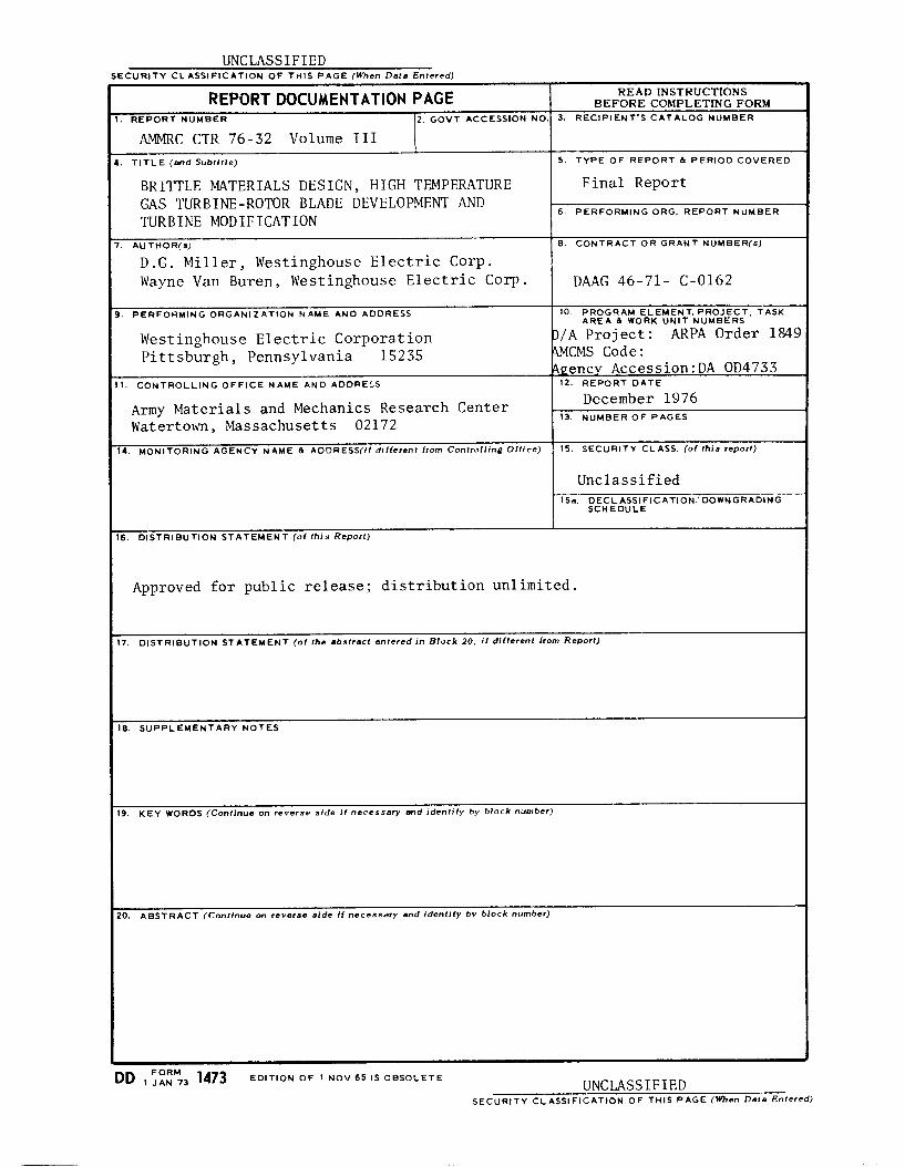
REPORTDOCUMENTATION PAGE READ INSTRUCTIONS BEFORE COMPLETING FORM
I. REPORT NUMBER 2. GOVT ACCESSION NO. 3. RECIPIENT’S CATALOG NUMBER
AMMRC CTR 76-32 Volume III I. TITLE (and Subtitle) 5. TYPE OF REPORT & PERIOD COVERED
BRITTLE MATERIALS DESIGN, HIGH TEMPERATURE Final Report GAS TURBINE-ROTOR BLADE DEVELOPMENT AND TURBINE MODIFICATION
6. PERFORMING ORG. REPORT NUMBER
7. AU THOR(s) 8. CONTRACT OR GRANT NUMBER(s)
D.G. Miller, Westinghouse Electric Corp. Wayne Van Buren, Westinghouse Electric Corp. DAAG 46-71- C-0162
3. PERFORMING ORGANIZATION NAME AND ADDRESS 10. PROGRAM ELEMENT, PROJECT, TASK AREA & WORK UNIT NUMBERS
Westinghouse Electric Corporation 3/A Project: ARPA Order 1849 Pittsburgh, Pennsylvania 15235 QKMS Code:
Agency Accession:DA OD4733 Il. CONTROLLING OFFICE NAME AND ADDRESS 12. REPORT DATE
Army Materials and Mechanics Research Center Watertown, Massachusetts 02172
December 1976 13. NUMBER OF PAGES
14. MONITORING AGENCY NAME & ADDRESS(if different from Controlling Office) 15. SECURITY CLASS. (of this report)
Unclassified 15a. DECLASSIFICATION~DOWNGRADING
SCHEDULE
16. DISTRIBUTION STATEMENT (of thfs Report)
Approved for public release; distribution unlimited.
17. DISTRIBUTION STATEMENT (of the abstract entered in Block 20. if dffferent from Report)
19. KEY WORDS (Continue on reverse side if necessary and identify by block number)
20. ABSTRACT (Continue on reverse side if necessary and fdentlfy by block number)
DD FoRM 1473 1 JAN 73 EDITION OF 1 NOV 65 IS OBSOLETE UNCLASSIFIED SECURITY CLASSIFICATION OF THIS PAGE (When Data Entered)