BRINE CIRCULATED ICE THERMAL STORAGE SYSTEMS
46
1 1 BRINE CIRCULATED ICE THERMAL STORAGE SYSTEMS For Partial Ice Storage Air Conditioning Application By: T. S. Wan Date: April 15, 1994 (1st draft 4/4/90) Copyright 1994 by T. S. Wan All rights reserved This article shall discuss the ice thermal storage systems using the secondary heat transfer fluid (brine) instead of direct refrigerant. Direct refrigerant type ice thermal storage systems are discussed in the separate article. As explained in the article of the System Configuration for Ice Thermal Storage Application, no matter the ice thermal storage system is using brine or direct refrigerant, the system configuration should be considered in order to obtain proper operation and control of the system. Any ice thermal storage system, no matter it is brine system or direct refrigerant system; it consists of three major groups: (1) Refrigeration System. (2) The Ice Reserve Unit. (3) The Air Side System. In a brine circulated partial storage ice thermal storage system, the refrigeration unit is a brine chiller which is to supply the brine to the ice reserve unit to build the ice during off-peak hours in the evening and to supply cold brine from the ice reserve unit for air conditioning as needed during air conditioning cycle. The main reasons to use brine chiller instead of direct refrigerant are as the following: 1.0 Standard chiller such as reciprocating chiller, screw chiller or centrifugal chiller can be used. The initial investment is therefore, reduced. 2.0 Some of the ice reserve units are basically designed for the use of brine instead of direct refrigerant.
Transcript of BRINE CIRCULATED ICE THERMAL STORAGE SYSTEMS

1
1 BRINE CIRCULATED ICE THERMAL STORAGE SYSTEMS For Partial Ice Storage Air Conditioning Application By: T. S. Wan Date: April 15, 1994 (1st draft 4/4/90) Copyright 1994 by T. S. Wan All rights reserved This article shall discuss the ice thermal storage systems using the secondary heat transfer fluid (brine) instead of direct refrigerant. Direct refrigerant type ice thermal storage systems are discussed in the separate article. As explained in the article of the System Configuration for Ice Thermal Storage Application, no matter the ice thermal storage system is using brine or direct refrigerant, the system configuration should be considered in order to obtain proper operation and control of the system. Any ice thermal storage system, no matter it is brine system or direct refrigerant system; it consists of three major groups: (1) Refrigeration System. (2) The Ice Reserve Unit. (3) The Air Side System. In a brine circulated partial storage ice thermal storage system, the refrigeration unit is a brine chiller which is to supply the brine to the ice reserve unit to build the ice during off-peak hours in the evening and to supply cold brine from the ice reserve unit for air conditioning as needed during air conditioning cycle. The main reasons to use brine chiller instead of direct refrigerant are as the following: 1.0 Standard chiller such as reciprocating chiller, screw chiller or centrifugal chiller can be used.
The initial investment is therefore, reduced. 2.0 Some of the ice reserve units are basically designed for the use of brine instead of direct
refrigerant.

2
3.0 Standard chiller which mainly designed for chilled water can be rated for brine duty and the
chiller is a factory packaged unit, no need for the consultant engineer or owner to carry out the refrigeration system and refrigerant circuit design.
4.0 Standard packaged unit is used and the field installation work is minimized. 5.0 Refrigerant charge is kept as minimum, particularly water cooled condenser is used. 6.0 Only brine piping is involved between the refrigeration unit and the ice reserve units. BRINE CHILLER: The brine chiller, no matter it is standard unit or special unit, the chiller consists of condenser, compressor and the brine cooler. The suction temperature of the compressor used for ice thermal storage operation changes constantly. Figure-1 shows the typical suction temperature changes of a compressor. When the beginning of the ice making cycle, say at 6:00 pm of the day, the supply brine temperature is relatively high at the beginning of the ice making cycle, therefore, the suction temperature of the compressor might be running at 28°F; The suction temperature drops when the ice is being built. The final pull down temperature of the compressor might be as low as 10°F at the final hour of ice making process for some of the ice builders. And then, the suction temperature of the compressor is increased to around 36°F for air conditioning supplement duty, until it is changed to back to ice duty at the end of the day and the beginning of the ice making cycle. Figure-1 shows the compressor suction temperature changes during the 24-hour cycle of ice making and air conditioning supplement operation. It is very obviously that the compression head of the compressor is changing all the time because the suction temperature changes all the time. Besides the suction temperature change, the condensing temperature is also changing between the day time and the night time. In view of this, therefore, the compressor used for ice thermal storage should be a variable head machine such as screw compressor (reciprocating compressor for smaller capacity) instead of constant head machine such as centrifugal. The best energy saving screw compressor is the compressor equipped with automatic control variable internal volume ratio (Vi) design. Together with automatic sliding vane control, a variable Vi screw compressor not only can meet all the load variation, it also can vary the internal volume ratio to save the energy consumption at the partial load and reduce head operation.

3

4
ICE BUILDERS: There several types of ice builder which are basically designed for the use with brine instead of refrigerant are available in the market. The performance and the characteristics of the brine circulated ice builders are outlined as the following: (A) ICE BALL ICE BUILDER: The suppliers of ice ball ice builder are YORK, CRYOGEL. York IceBalls (see Figure-2)
and Cryogel ice balls are having same diameter which is 4". The nominally capacity is 77 IceBalls per Ton-Hour ice storage.
The ice ball is an encapsulated ice type ice builder. The water is housed inside the ball. The
balls are placed in a tank. Brine is circulated through the tank to make or to melt the ice (see Figure-3).
The approximate space for storage is about 2.0 to 2.5 cu. ft. per TR-HR for pressure vessel
and 2.5 to 3.0 cu. ft. per TR-HR for open tank. The most important consideration in ice ball ice builder arrangement shall be to avoid short
circuit in brine flow. All the brine must flow evenly over the balls inside the tank during the charge and discharge cycles. Short circuit flow (see Figure-4 and Figure-5) will result in not enough tr-hrs being charged and short of capacity when it is discharged. Careful arrangement of the ice balls should be made when horizontal tank is used. The best arrangement for ice is the vertical tank (see Figure-6). The brine even flow is almost automatic when the ice balls are floating to the top portion of the tank.
(B) CALMAC ICE BUILDER: Calmac ice builder is a solid ice on coil type ice builder which is packed with 5/8"
polyethylene tunings in a cylindrical plastic tank (see Figure-7) and the tank is insulated with polystyrene insulation. The brine is circulated in the tubes packed inside the tank. The tank is filled with water. The water inside the cylindrical tank freezes solid during the charge (ice making) cycle and the ice melts and cooling down the brine in the tube during discharge cycle.
Smaller tanks are cylindrical and the largest one is rectangular. The largest single tank is
model 1500A, the size is 268" x 96" x 102"(H), ice storage capacity is 486 tr-hrs, the volume of water/ice of the tank is 4,860 gallons.
The Calmac ice builder cannot be buried underground completely. Calmac recommends
burial 12" below the top of the tank.

5

6

7

8
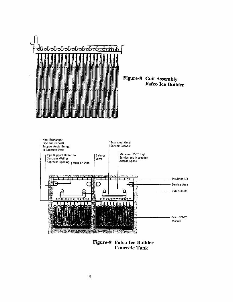
(C) FAFCO ICE BUILDER: Fafco ice builder is an ice on coil/tank ice builder. The coil assembly is made from 1/4" to
5/8" polyethylene tunings connected with glued plastic connectors and plastic welding. Figure-8 shows the typical coil assembly. The Fafco ice builder can be supplied with the tank for smaller tr-hr capacity and it also can be supplied with coil modules for concrete tank installation as shown in Figure-9.
The largest assembled unit with tank is Model 590. The overall dimensions of this model
are 236" x 96" x 82" (H). Ice storage capacity is 472 TR-HR. The diameter of Fafco coil is fairy small, 1/4"OD, therefore, it is very sensitive to dirt. The
tubes will be blocked with dirts if the brine is not filtered or the filter is not cleaned properly.
9

10
(D) REACTION ICE BUILDER: Reaction ice builder is also an encapsulated ice builder. The Lens, as called by the maker
Reaction Thermal is a rectangular shape with de-ionized water housed by plastic container. The size of the Lens is 32" x 12" x 1-3/4". Lenses are loaded and stacked in a tank. Brine is circulated through the tank to make the ice or to melt the ice. Figure-10 and Figure-11 show the Lenses on top of each other and the brine flow between the Lenses. Figure-12 shows the typical tank module for the Lenses. Reaction Thermal provides more than 30 sizes of tank module. Lenses are loaded into the tank module in the field.
Proprietary Reactor brine is recommended instead of common brine of Ethylene Glycol by
Reaction Thermal. The largest tank module is Model SM4112C, diameter 12 feet, length 69 feet, ice storage
capacity of 3,455 TR-HR. The medium size is Model SM2510C, diameter 10 feet, length 60 feet, ice storage capacity of 2,080 TR-HR. The smaller size is Model SM407C, diameter 7 feet, length 24 feet, ice storage capacity of 389 TR-HR.
(E) ICE-ON-COIL ICE BUILDER: Ice-on-coil ice builder is constructed by steel coil. The suppliers are BAC, Evapco and
others. The brine is circulated through the steel coil, the ice is form outside of the coil. Figure-13 shows the factory assembled ice reserve unit with tank. The Figure-14 shows the
bare coil assembly for field erected concrete tank and the coil inside of the concrete tank. Unlike other brine circulated ice builder, the ice on steel coil type ice builder, the ice
melting can be internally or externally as shown in Figure-15 and Figure-16. The discharge efficiency of this ice-on-coil ice builder is very good if the chilled water is
arranged to contact with the ice such as shown in Figure-16. The direct melting arrangement is the standard arrangement of ice on steel coil ice builder.
The largest factory assembled unit is Model TSU-1440D from BAC. The overall
dimensions of this unit are 11'-9" x 41'-9" x 7'-7" (H). Storage capacity is 1,440 TR-HR of ice.

11

12

13

14

15
(F) EUTECTIC SALT ICE BUILDER: The Eutectic Salt ice builder is made by Transphase System, Inc. It is a form of
encapsulated ice. The Eutectic salt in a polyethylene housing is called Transcool Container (See Figure-17). The Transcool Containers are stacked on top of each other and loaded into a tank or in a concrete tank in the field.
The Eutectic Salt is designed to change phase at 47°F. This temperature is considered too
warm for most chilled water air conditioning application and it too high and not economically justifiable for lower temperature thermal storage application.
The size of each Transcool Container is 24" x 8" x 1.75". The latent heat fusion thermal
storage capacity of each Transcool Container is 459.2 Btu; The sensible heat storage is about 4.48 Btu/°F above the freezing point and 3.36 Btu/°F storage capacity below the freezing point.
All the ice storage capacities indicated above are the latent TR-HR storage capacity, sensible TR-HR for the water is not included. ICE BUILDER MANUFACTURERS: The major manufacturers who provide the ice builder for ice thermal storage application are as the following: Ice Ball - Cryogel - Mitsubishi - York Solid Ice on Coil - Calmac Ice on Coil/Tank - Fafco Ice on Coil - BAC - Evapco Ice Lens - Reaction Thermal Eutectic Salt - Transphase System

16

17
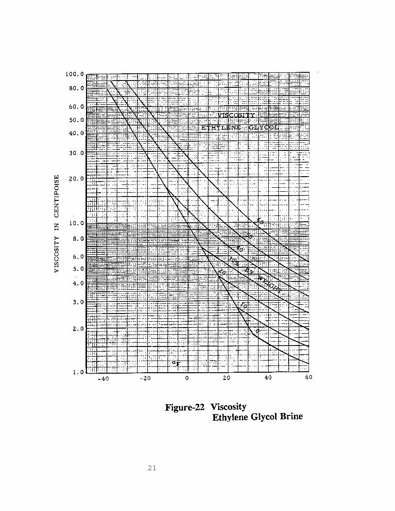
There are other brine circulated types of ice builders in the research and development stage and are not available in the commercial market. Direct refrigerant type ice builders are not included in this article and they are being discussed in the separate article. BRINE TO BE USED: The brine used for the brine circulated ice thermal storage systems is mainly Ethylene Glycol for most installations. The determination of concentration of the brine depends on design evaporative temperature of the refrigeration unit and the final pull down evaporative temperature required for the ice builder. The brine is an anti-freeze heat transfer fluid. The freezing point depends on the concentration of the brine. For Ethylene Glycol circulated ice builders, the brine concentration required is about 25% to 30% by weight. The brine concentration is usually recommended by the ice builder manufacturer. Be sure to check the brine concentration required with the ice builder manufacturer to see if it is based on weight percent or by volume percent. At the same percentage, percent by volume will have lower freezing point than the percent by weight. See Figure-18 for the conversion between percent by weight and percent by volume for the Ethylene Glycol brine. The formula for the calculating heat load and the brine flow are as the following: BTU/HR = 499.8 x GPM x S.G. x Cp x (T2 - T1) --------------------------- (1) BTU/HR - Heat load GPM - Gallons per min. flow of the brine S.G. - Specific gravity of the brine Cp - Specific heat of the brine, Btu/Lb-°F T2 - Entering temperature of the brine, °F T1 - Leaving temperature of the brine, °F The specific gravity and the specific heat of the brine are always taken at the mean temperature of the brine. The thermodynamic characteristics of the Ethylene Glycol brine are shown in the following figures: Figure-18 - Freezing point, °F Figure-19 - Specific gravity, to 60°F of water Figure-20 - Specific heat, Btu/Lb-°F Figure-21 - Conductivity, Btu/Hr/Sq.Ft./°F/Ft Figure-22 - Viscosity, Centipoise

18

19

20
21

22
Figure-23 is the pressure drop correction factors which are to be used to calculate the brine pressure drop in the brine circuit or the pressure drop through the cooler. For example: Refrigeration capacity of 450 TR. Ethylene Glycol brine flow, 25% by weight.
Chiller entering temperature is 29°F; leaving brine temperature is 24°F. The average brine temperature = (29 - 24)/2 = 26.5°F 25% by weight brine is 23% by volume. From the Ethylene Glycol brine characteristic figures: Freezing point : 12.2°F Specific gravity : 1.037 Specific heat : 0.917 Viscosity : 4.0 Conductivity : 0.295 Pressure drop correction factor : 1.20 Brine temperature range = 29 - 24 = 5°F Heat load = 450 x 12,000 = 5,400,000 Btu/Hr. From formula (1), the brine flow is calculated at 2,272 GPM for the 25% by weight Ethylene Glycol, 450 TR, brine entering temperature 29°F, leaving brine temperature of 24°F. The Ethylene Glycol brine should be with corrosion inhibitor. Some major chemical companies have commercially available the ready mixed Ethylene Glycol based heat transfer fluid with inhibitor added. The trade name of such heat transfer fluid from Dow Chemical is called DOWTHERM SR-1 and the UCARTHERM is supplied by Union Carbide. BRINE PRESSURE DROP THROUGH PIPE FLOW: Brine pressure drop through the pipe line shall be calculated to base on water flow and then apply the brine pressure drop correction factor obtained from the Figure-23. For example: 2,272 GPM, 25% by wt. Ethylene Glycol brine flow through a 6" fairly smooth steel pipe. The pressure drop of 2,272 GPM water through a 6" fairly smooth steel pipe is 13.5 Psi/100'.

23
From Figure-19, the specific gravity of the brine is 1.038 and the viscosity is 4.22 cp from Figure-16. The brine pressure correction factor from Figure-23 is 1.22. Therefore, the brine flow of 2,272 GPM through a 6" pipe is 13.5 x 1.22 = 16.5 Psi/100'

24
The rule of thumb for brine pressure drop in a brine circulated ice thermal storage system is about 25% more than the equivalent water flow pressure drop. The pump flow and the pumping head should base on the brine at the design operating conditions. HEAT EXCHANGER TUBE MATERIAL: In a closed circuit air conditioning system, copper tubes or carbon steel tubes in heat exchanger can be used if the Ethylene Glycol is with corrosion inhibitor. Heavier tube wall should be used instead of 22 or 24 BWG. 20 BWG copper tubes or 16 BWG carbon steel tubes are recommended. BRINE DESIGN TEMPERATURE AND BRINE CONCENTRATION: The brine temperature range should be designed as small as possible to obtain lower brine mean temperature at the same leaving temperature. However, the flow will be too large if the brine temperature range is getting too small. Most ice builder manufactures recommend the brine temperature range of 5 to 6°F. The design entering and leaving temperature of the brine for ice making duty (charging cycle) and the brine concentration are to be recommended by the ice builder manufacturer. The following data are being used in most cases: Group-1: For all brine circulated ice builders except the Group-2 and Group-3:
Concentration of the brine: 25% by volume of Ethylene Glycol brine. Entering brine temperature: 24°F
Leaving brine temperature: 29°F Group-2: For ice on steel coil ice builders:
Concentration of the brine: 30% by volume of Ethylene Glycol brine. Entering brine temperature: 18°F
Leaving brine temperature: 24°F Group-3: For Eutectic Salt thermal storage: Transphase is mostly used for chilled water storage The brine leaving temperature from the ice builder for air conditioning duty (discharge cycle) are

25
depending upon the system design, system configuration and discharge efficiency. The brine temperature leaving the ice builder during discharge cycle will vary. It might be too cold during the early hours of discharge cycle and it might too warm during the final hours of the operation. Therefore, a control must be provided to prevent too much TR-HR is taken out from the ice reserve unit and discharge efficiency must be checked to ensure that the TR-HR is available at the end of the discharge cycle. The feasible lowest design leaving brine temperature during discharge cycle for the ice builders under Group-1 is 38°F. The chilled water leaving the ice builder under Group-2 can be as low as 32°F. For practical application purpose, the chilled water temperature leaving the ice builders of Group-2 should be designed around 33 to 34°F. CHARGE AND DISCHARGE EFFICIENCY: All the ice builders have charge and discharge efficiency. Charge efficiency is how easy to store the ice during ice making cycle at the design brine temperatures, i.e. the TR-HR to be put into the ice reserve unit. The discharge efficiency is the TR-HR to be taken out from the ice reserve unit at the desired design temperature. Practically, all the brine circulated ice builders, except the ice on steel coil ice builder, have somewhat poor discharge efficiency at the final hour of discharge. Lower the design discharge temperature, worse the discharge efficiency would be. Therefore, whenever brine circulated ice thermal storage system is used, the ice reserve unit must be carefully selected and checked to make sure the ice builder performance meets the requirements. The criteria for selecting brine circulated ice builder are as the following: (1) CHARGE CAPACITY: The ice storage unit must have the storage capacity to store the total TR-HR and must
complete the full charge within the storage hours under the design conditions of brine temperatures, the chiller TR and the brine flow as specified.
(2) DISCHARGE CAPACITY: The ice reserve unit must be able to deliver the TR-HR required at the design leaving
temperature as specified, at the design flow, at every hour during the discharge cycle, particularly, the final hours of operation.
The ice builder must meet both the charge and discharge capacity and also the unit must be able to be installed in the space provided. The discharge efficiency will be very low if the leaving temperature from the ice builder is low. The discharge efficiency for some of the ice builders under Group-1 will drop down to 60% or lower if the leaving temperature requirement is below 38°F. That means the ice builder should have 40% or

26
more additional equipment surface in order to compensate the low discharge efficiency. Ice on steel coil brine circulated ice thermal storage units have very good discharge efficiency if the chilled water circuit is arranged to have direct contact with the ice as shown in Figure-16. SYSTEM CONFIGURATION AND VARIOUS SYSTEMS: The relative positions between the brine chiller, the ice reserve unit and the control should be arranged in line with the system configuration as discussed in the article of the System Configuration for Ice Thermal Storage Systems. It is very important that the system should be designed in such way that the performance of the system is sure at all the times during the charge and/or discharge cycle, no matter it is full load or partial load conditions. The typical arrangement of brine circulated refrigerating unit (Chiller) coupled with various types of ice reserve unit are shown below: 1.0 BRINE CHILLER WITH ICE BALLS ICE RESERVE UNIT:
1.01 Figure-24 shows the ice thermal storage system which consists of a brine chiller and the ice balls ice reserve unit.
1.02 Plate type heat exchanger are used for the purpose of confining the brine within the
engine room. Chilled water is used in the secondary circuit instead of brine.
1.03 The purpose of using plate type heat exchanger:
1.03.01 To prevent the back flow of the heat transfer fluid for high rise building.
1.03.02 To reduce the system charge of Ethylene Glycol brine and to reduce
the cost of Ethylene Glycol.
1.03.03 To provide a better heat transfer for air side equipment by using water instead of brine.
1.03.04 To reduce the pumping head for the secondary circuit.
1.04 The system can be arranged without the plate type heat exchanger provided that the
system has no back flow problem. In this case, entire piping system will be with Ethylene Glycol brine.

27

28
1.05 The use of plate type heat exchanger depends upon the piping system design. Some cases, one plate type heat exchanger is used instead of two.
1.06 The typical operating conditions for the brine chiller are: 1.06.01 Night time charge cycle (ice making) duty: Brine leaving temperature: 24°F Brine return temperature: 29°F 1.06.02 Day time air conditioning duty: Brine leaving temperature: 49°F
1.07 The brine chiller is a screw type chiller, factory packaged standard unit, designed for ice thermal storage application.
1.08 Screw compressor type chiller should be always used for better head capability and
better partial load performance for the ice thermal storage system.
1.09 During night time ice making duty, the brine valves (n) are opened and all valves (d) are closed. Air conditioning system is not operated. At the design point, 24°F brine is supplied to the ice reserve unit to build the ice, return brine temperature is 29°F.
1.09 During day time operation air conditioning supplement, all the valves (n) are closed
and all the valves (d) are opened. The cold brine at 49°F is supplied to first stage plate type heat exchanger to cool the return primary chilled water down to an intermediate temperature from return temperature of 52°F. The chilled water is further cooled down to 42°F by the second plate type heat exchanger where cooled brine is circulated from the ice reserve unit.
1.10 The brine from ice reserve unit is to be controlled by a mixing valve to produce a
constant brine supply temperature of 39°F to the second stage heat exchanger.
1.11 It is vital important that the ice balls must be arranged in the tank to avoid any possible of short circuit in the brine flow.
1.12 The control of the change over from ice making and air conditioning operation is
controlled by the facility automation or building management.

29
2.0 BRINE CHILLER WITH FAFCO TYPE ICE RESERVE UNIT:
2.01 Figure-25 shows a screw brine chiller with Fafco type ice builder. The system arrangement is basically the same as the ice balls ice reserve unit except some the valve locations. Therefore, most descriptions in 1.0 are applicable for the Fafco ice builder.
2.02 The heat transfer efficiency of Fafco ice builder is very good. However, as indicated
before, the tubes used for the ice builder coil is small and therefore, the brine should be clean to avoid blockage of the tubes.
3.0 BRINE CHILLER WITH CALMAC TYPE ICE RESERVE UNIT:
3.01 Figure-26 shows a screw brine chiller with Calmac type ice builder.
3.02 The system arrangement as shown in Figure-26 is basically the same as the ice balls or Fafco type ice reserve unit except some of the valve locations.
4.0 BRINE CHILLER WITH STATIC ICE RESERVE UNIT:
4.01 Figure-27 shows the ice thermal storage system which consists of a brine chiller and the brine circulated static ice reserve unit.
4.02 The difference of this ice reserve unit as compared to other types of ice builder is
that the heat transfer fluid for discharge cycle is water which is through the ice tank instead of the brine circuit (see Figure-16). The plate type heat exchanger is used to isolate the brine from the chilled water circuit.
4.03 The system can be arranged to have the chilled water flow directly through the ice
reserve unit without the plate type heat exchanger provided that no back flow problem for the system.
4.04 The ice on steel coil can have same arrangement as other brine circulated system
such as Fafco or Calmac as shown in Figure-15. But, the benefit and the advantage of ice-on-coil of having direct contact between chilled water and the ice are not utilized in this case.

30

31

32

33
4.05 The design brine temperatures for ice-on-coil static ice reserve unit are general
lower than other brine circulated type ice builders. However, this disadvantage is offset by the advantage of having lower chilled water temperature available for the air side. For illustration purpose, the brine chiller is designed to have the operating conditions as the following:
4.05.01 Night time charge cycle (ice making) duty: Brine leaving temperature: 18°F Brine return temperature: 24°F 4.05.02 Day time air conditioning duty: Brine leaving temperature: 43°F Brine return temperature: 50°F
4.06 Again, screw compressor chiller should be always used for better head capability and better partial load performance for the ice thermal storage system.
4.07 During night time ice making duty, the brine valves (n) are opened and the valves (d)
are closed. Air conditioning system is not operated. At the design point, the 18°F brine is supplied to the ice reserve unit (the coil), return brine temperature is 24°F.
4.08 During day time air conditioning supplement, all the valves (n) are closed and all the
valves (d) are opened. The cold brine at 43°F is supplied to the first stage plate type heat exchanger to cool the return primary chilled water down to an intermediate temperature about 45°F from return temperature of 56°F. The chilled water is further cooled down to 36°F from the intermediate temperature of 45°F by the second plate type heat exchanger where icy water is supplied from the ice reserve unit at 34°F.
4.09 The icy water from ice reserve unit is to be controlled by a mixing valve to produce
a constant supply temperature of 34°F to the second stage heat exchanger.
4.10 Chilled water temperature range of 20°F (56°F-36°F) can be used for this case because icy water provided by the ice reserve unit. Smaller chilled water gpm flow is resulted from larger water temperature range, this reduces the initial cost of chilled water system; lower pumping horsepower. With lower chilled water temperature, supply air temperature to the conditioning space can be lower, this will reduce the installation cost of air system and lower the fan horsepower as well.
4.11 The control of the change over from ice making and air conditioning operation is
controlled by the facility automation or building management.

34
STANDARD AND NONE STANDARD BRINE CHILLER SYSTEMS: The brine chiller used for the brine circulated ice thermal storage systems can be either standard product of packaged screw chiller or none standard system. None standard system can be specially designed skid-mounted unit or it can be field erected brine refrigerating system. Various typical standard and none standard refrigeration systems used with the ice reserve unit are illustrated as the following: SYSTEM-AA: STANDARD UNIT: Figure-28 shows a standard factory packaged brine chiller with an ice reserve unit and a plate type heat exchanger. Figure-29 and Figure-30 show the flow line diagram for the system. SYSTEM-BB: SPECIAL UNIT WITH WATER COOLED CONDENSER: Figure-31 shows a special refrigeration brine chilling system with an ice reserve unit and a plate type heat exchanger. Special refrigeration system has to be used instead of standard packaged chiller for some installations for the reasons such as load variation, capacity, heavy duty application, none standard pass arrangement in the cooler, special code requirements, special construction of the pressure vessels and/or heat exchanger, local conditions and etc. The special refrigeration brine chiller shown in Figure-31 consists of water cooler condenser, industrial type screw compressor unit with oil separator, brine cooler and a high pressure receiver. This system can be field erected or it can be factory assembled skid mounted an unit. The system can be with two compressors or with any special requirement. Figure-32 shows the function of the system for night time ice making operation. The Figure-33 is the system for day time air conditioning with design operating conditions indicated.

35

36

37

38

39

40

41
SYSTEM-CC: SPECIAL UNIT WITH EVAPORATIVE CONDENSER: Figure-34 shows a special refrigeration brine chilling system with evaporative condenser, ice reserve unit and a plate type heat exchanger. Some installation prefers evaporative condenser to improve the energy consumption. This special refrigeration brine chilling system can be field erected or factory skid-mounted. The factory skid-mounted package can include the screw compressor unit with oil separator, brine cooler and the receiver. The evaporative condenser can be shipped separately for field connection. Figure-35 shows the function of the system for night time ice making operation. The Figure-36 is the system for day time air conditioning operation with design operating conditions indicated. SYSTEM-DD: SPECIAL UNIT WITH SEPARATE COOLERS All the brine circulated ice thermal storage systems discussed previously are basically the partial storage system. The same chiller heat exchanger is used to produce the cold brine for ice making (charge) duty and to produce the chilled brine at higher temperature for air conditioning supplement during day time operation. The heat transfer coefficiency for the brine is not as good as water even it is at higher temperature. The evaporative temperature can be higher and power consumption can be lower if the brine is replaced by water during day time operation. However, it is not very easy to switch the brine/water and also mixing problem is also involved if same chiller heat exchanger is used for both duties. In view of this, a separate water chiller is used in addition to the brine cooler in a special system as shown in Figure-37. The special refrigeration system shown in Figure-37 consists of screw compressor unit with oil separator, evaporative condenser, high pressure receiver, brine cooler shell-and-tube heat exchanger and water cooler shell-and-tube heat exchanger. The heat exchanger can be designed to be surge drum type instead of single shell design; The compressor can be multiple units instead of single unit; Water cooled condenser can be used instead of evaporative condenser. Again, this special refrigeration system can be either field erected or factory skid-mounted package. During the night time ice making duty, the valves (n) are opened and the valves (d) are closed. The liquid refrigerant is supplied to the brine cooler, suction gas is returned to the screw compressor. The brine is being cooled down to about 24°F or lower by the brine cooler. The brine is circulated through the ice reserve unit to make the ice.

42

43

44

45

46
During the day time operation for air conditioning supplement, the valves (n) are closed and the valves (d) are opened. The liquid refrigerant is now supplied to the water chiller instead of brine cooler, the gas from water chiller is returned to the compressor suction. The chilled water from the system is pumped directly through the water chiller as first stage cooling, the chilled water is further cooled down by the cold fluid from the ice reserve unit through a plate type heat exchanger. OTHER ARTICLES RELATED TO ICE THERMAL STORAGE. The other information related to ice thermal storage application is available in separate article as the following: (1) The Fundamental of Ice Thermal Storage. (2) System Configuration for Ice Thermal Storage. (3) Direct Refrigerant Ice Thermal Storage Systems. (4) Brine Circulation Ice Thermal Storage System – Case System Design Illustration.