Briefing to the National Research Council Committee on...
62
Briefing to the National Research Council Committee on An Assessment of Concepts and Systems for U.S. Boost-Phase Missile Defense in Comparison to Other Alternatives Theodore A. Postol Professor of Science, Technology, and National Security Policy, Massachusetts Institute of Technology Voice: 617 253-8077; e-mail: [email protected] George N. Lewis Associate Director, Peace Studies Program, Cornell University Voice: 607 255-8914; e-mail: [email protected] National Research Council Washington D.C. May 19, 2010 MIT Science, Technology, and Global Security Working Group 1 A National Defense Strategy Based on Provably False Assumptions Assumptions Used by the DoD for GMD Performance Cannot Possibly be Known Hence, Actual Performance of the GMD is Unknowable The Record of “Proven Reliability” of the Navy’s SM-3 Interceptor Actually Shows that the SM-3 Will Be Highly Unreliable in Actual Combat Conditions Missile Defense in-hand 2
Transcript of Briefing to the National Research Council Committee on...

Briefing to the National Research Council Committee on An Assessment of
Concepts and Systems for U.S. Boost-Phase Missile Defense in
Comparison to Other Alternatives
Theodore A. Postol Professor of Science, Technology, and National Security Policy, Massachusetts Institute of Technology
Voice: 617 253-8077; e-mail: [email protected]
George N. Lewis Associate Director, Peace Studies Program, Cornell University
Voice: 607 255-8914; e-mail: [email protected]
National Research Council Washington D.C.
May 19, 2010
MITScience, Technology, and
Global Security Working Group
1
A National Defense Strategy Based on Provably False Assumptions
� Assumptions Used by the DoD for GMD Performance Cannot Possibly be Known Hence, Actual Performance of the GMD is Unknowable
� The Record of “Proven Reliability” of the Navy’s SM-3 Interceptor Actually Shows that the SM-3 Will Be Highly Unreliable in Actual Combat Conditions
Missile Defense Theorists Technology is Already in-hand Current Missile Defense Systems Work US Assumptions About Robust Missile Defenses will Cause Proliferators to Give Up
2

Main Points to be Made in This briefing (1 of 3)
� North Korea is only one successful flight test away from demonstrating an ICBM that would be able to deliver a nuclear warhead to almost anywhere in the Continental United States.
� Since the United States is building the wrong missile defense-systems to deal with this,It cannot be ruled out that the United States might eventually become vulnerable to nuclear-armed coercion.
� This potential future problem can be addressed as there are definitely boost-phase missile defense-systems that could provide for the strategic continental defence of the United States from both North Korean and Iranian long-range ballistic missiles.
� However, under current conditions, Boost-Phase ballistic missile defense systems will never be developed or built, as the Pentagon remains solely focussed on building unworkable exo-atmospheric missile defenses.
� Unless there is a serious evaluation of the true shortcomings of these exo-atmospheric defenses, they will remain the centerpiece of the Pentagon’s ballisitc missile defense program, and bureaucratic politics will guarantee that there will be no money for the development of far more capable, reliable, and robust boost-phase missile defenses.
� There is also a very serious problem with the technical competence of upper level management in the Missile Defense Agency and elsewhere in the Pentagon. 3
Main Points to be Made in This briefing (2 of 3) � This is manifest in the record of one technically naïve missile defense solution being
substituted for another. � For example, the adoption of post-boost phase missile defenses under the naïve belief
that it takes time to deploy countermeasures after rocket motor shutdown. This reveals a startling lack of technical sophistication among managers at MDA.
� There is also a problem with the approach of political leadership to this problem, which has inadvertently encouraged repeated misrepresentations in the missile defense program by not holding individuals accountable for false statements they have and continue to make.
� In summary, none of the actions needed to get proper management into the missile defense program will be solved unless individuals and organizations are held accountable for misinformation that is being disseminated.
� It is ridiculous to call the missile defense testing that has been conducted to date by the Pentagon realistic.
� Even in orchestrated experiments, the systems fail catastrophicly when anything unexpected happens (Note Ronald Kadish’s statement when the canister carrying the large balloon failed to open in the IFT-6).
� In the FTG-06, the scene recognition system of the Sea-Based X-band radar failed because of a trivial unplanned event when a rocket motor unexpectedly expelled small pieces of debris. 4

Main Points to be Made in This briefing (3 of 3)
� The SM-3 failures and the FTG-06 failure are simply another manifestation of the GMD and SM-3s profound vulnerabilities to decoys.
� This vulnerability was covered up in 1997 and 1998 when the IFT-1A and IFT-2 proof-of-concept experiments showed that the GMD could be fooled by a subset of the decoys flown in those experiments.
� It is now more than ten years later and the GMD has still not been tested against these decoys.
� Before the Gulf War of 1991 Patriot had a record of 17 successes out of 17 intercept tests. In the Gulf War of 1991 the actual intercept rate, defined as destruction of SCUD warheads, was almost certainly 0 out of 44.
� Most recently, the SM-3 has been misrepresented to the President as a “proven and reliable” missile defense system. In fact, the Pentagon’s own data shows the opposite.
� The Pentagon’s test data instead shows that the SM-3 is fragile and brittle, and unlikely to perform in combat at a level much higher than that allowed by chance.
� SM-3 Block IA kill vehicle will be even more vulnerable to countermeasures than the already fragile and vulnerable GMD kill vehicle, as the SM-3 kill vehicle cannot measure the temperature of objects (see MIT Lincoln Laboratory IR data).
5
What Needs to Be Done
� No sound technical decisions in missile defense will be possible unless there are science-based assessments of the true capabilities of missile defense systems.
� It is the responsibility of the technical community to stop playing political games with the truth.
� The community needs to confront the fact that strategic boost-phase ballistic missile defenses, which actually could provide for the strategic defense of the continental United States, will never be developed unless the truth about the fundamental limitations of exo-atmospheric defenses is addressed.
� The abysmal failure of the Pentagon to establish realistic standards for testing missile defense systems must be vigorously addressed and corrected.
� Real tests of the GMD and SM-3 systems must be done against simple realistic decoys of the kind that were flown in the IFT-1A and IFT-2 in 1997 and 1998.
� Unless the informed technical community takes responsibility as advisors to the nation, the next time the nation depends on missile defenses, one can only hope it will not be against nuclear-armed ballistic missiles.
6

Important Consequences of the Current Failures to Properly Address the Real Technical Issues Associated with Exo-Atmospheric Missile Defenses
� North Korea is only one successful flight test away from demonstrating an ICBM capable vehicle that could range the entire Continental United States. The United States could become vulnerable to such an ICBM threat, because it is building the wrong missile defense-systems to deal with it.
� There are definitely boost-phase missile defense-systems that could provide for the strategic continental defence of the United States from ICBM attack from North Korea and Iran.
� However, the new missile defense strategy de-emphasizes these defense-systems in favor of unproven, unworkable, and far more expensive systems.
� This failure to emphasize workable systems in favor of unworkable systems is a consequence of years of misrepresentations and coverups by the Missile Defense Agency, which has not been forcefully addressed by the nation’s political leadership.
� One consequence of these failures is that the US is poised to deploy systems that are easy to defeat, which will likely fail to deter, or actually stimulate, ballistic missile proliferation.
� If the current emphasis on exo-atmospheric systems continues without the imposition of proper testing statndards and oversight, we can expect with near certainty that proliferators like North Korea and Iran will introduce highly effective countermeasures against these systems.
� These proliferators could, and likely would, sell these countermeasures to client states. 7Important Additional Costs that are not Offset by Benefits Due to the Ongoing
Failures to Properly Address the Real Technical Issues Associated with Exo-Atmospheric Missile Defenses
� The United States could damage its relations with allies and friends by pushing on them false and unreliable solutions to a real security problem.
� The United States will antagonize both Russia and China with massive defense deployments that have the appearance of being designed to be “flexibly” adaptable to deal with Russian and Chinese strategic forces.
� The negative effects of a costly and energetic US program that appears to be aimed at blunting Russia’s strategic retaliatory strike forces will sow distrust of the US within the Russian government and will create significant barriers to future arms reductions efforts.
� If arms reductions efforts with Russia come to a halt, this will have serious adverse effects on Russian and US efforts to maintain the viability of the Nonproliferation Treaty of 1968, which is already under considerable pressure due to the US-India Nuclear Deal.
8

Basic Issues to Be Discussed in this Briefing
1. Important aspects of the nations new nuclear strategy, laid out in the Nuclear Posture Review (NPR), rests on conclusions from the Department of Defense's Ballistic Missile Defense Review (BMDR), released in February 2010.
2. The BMDR claims that all the fundamental technical problems associated with current missile defense systems have been solved.
3. This translates into the conclusion that the United States is now and for the foreseeable future able to defend itself from limited ICBM attacks.
4. It also translates into a conclusion that the United States can build sufficiently reliable and robust ballistic missile defenses that it will cause potential adversaries to deemphasize their reliance on ballistic missiles as instruments of intimidation.
5. However, as will be shown in this briefing, there are no new material facts to support any of the claims in the BMDR that suggest that the United States is now in a position to defend itself from limited ICBM attacks or that any of the fundamental unsolved problems associated with high-altitude ballistic missile defenses have been solved.
6. In fact, as this briefing will show, the most recent ballistic missile defense flight-test data released by the Department of Defense and the most recent failed test of the ground-based missile defense system in January show quite the opposite.
9Relevant Information About the Arms Control Today Article
and the Associated White Paper Being Provided to the Committee
� The PDF and printed versions of the Arms Control Today article includes copies of critical endnotes that contain powerful additional information that substantially expands upon the article’s content.
� The associated White Paper (which NRC information control was not provided to the Committee until today) contains a substantial amount of highly relevant additional information that could not be put into the original article because of space considerations. Endnote 1 in the Arms Control Today article refers to the White Paper.
� An expanded search of Missile Defense Agency documents show that they contain quite a bit of evidence that the Missile Defense Agency has not been accurately representing the record of accomplishments in ballistic missile flight tests.
10

An Inappropriate Security System that is Designed to Inhibit National Research Council’s Investigation
Materials for the National Research Council Committee were sent by e-mail on May 5. After one week (May 12) I found out that the most informative part of the transmitted Committee materials had not been distributed. The reason was that the National Research Council information system had the following questions: 1. The White Paper is unclassified; however, is it non-restrictive? Can it be released for
unlimited distribution? If so, then the White Paper will be placed in the Public Access File that is associated with this study. (By the way, I checked for the White Paper on the Internet, but I did not find it.)
2. In regard to the unclassified MIT Lincoln Laboratory slides that are Figures 4, 5, 6, and the title page of Eric Evans’ brief (shown in the reference section), I need to know what process was used to vet these slides so that they are unclassified, non-restrictive, and public releasable for unlimited distribution.
11Relevant Information in this Briefing About Issues Discussed in
the Arms Control Today Article and the Associated MIT White Paper
Misrepresentation of the SM-3 System as “Proven”
1. The Article and White Paper show that the Department of Defense’s owned ballistic missile defense flight test data contradicts the technical conclusions of the Ballistic Missile Defense Review.
2. In particular the two papers show that when the SM-3 interceptor was tested against rockets carrying warheads, and some times rockets not carrying warheads, the SM-3 kill vehicle almost always failed to hit the warhead section. This means that the warhead would not have been destroyed in 8 to 9 out of 10 intercept tests that were called successful by the Missile Defense Agency.
3. In testimony before the Congress in 1992 the Army was questioned about the greater than 90% intercept rate it had earlier claimed for the Patriot missile in the Gulf War of 1991. The army explained that its claims were not false because it defined intercept as an event where "a Patriot and a stud test in the sky." The same misleading statements about what constitutes successful intercepts are again being made by the Missile Defense Agency – this time with regard to the results of the SM-3 ballistic missile flight tests.
12

Relevant Information in this Briefing About Issues Discussed in the Arms Control Today Article and the Associated MIT White Paper
FTG-06 Failure and Its Relation to Vulnerabilities in the SM-3 Block IA Interceptor
4. The two papers explain how the most recent Ground-Based Missile Defense test on January 31, 2010, the FTG-06, failed because the defense-system encountered a special circumstance where it could not recognize the difference between the mock warhead and chunks of debris that were unexpectedly expelled by the spent rocket motor that launched the mock warhead.
5. They then explain how an adversary could intentionally create credible false targets that would without exception defeat the Ground-Based Missile Defense System in all circumstances.
6. The infrared and radar data released by MIT Lincoln Laboratory and discussed in the White Paper explains how chunks of debris that were unexpectedly expelled from a rocket motor in the FTG-06 caused the total collapse of the "scene recognition" process that is supposed to select the warhead from the cloud of deployment debris.
7. The MIT Lincoln Laboratory data shows that the SM-3 block IA kill vehicle will never be able to discriminate between a warhead and debris of the type encountered from the rocket motor in the FTG-6.
8. This is because the SM-3 Block IA kill vehicle cannot measure the temperature of the debris. This vulnerability will be eliminated with the Block IB kill vehicles and beyond, because these kill vehicles can observe targets in two wavelength bands, allowing them to distinguish hot objects from cooler near-room temperature objects.
13Relevant Information in this Briefing About Issues Discussed in
the Arms Control Today Article and the Associated MIT White Paper
Misrepresentations of GMD Proof of Concept Tests as Successful When in Fact they Failed
9. The two papers explain that the IFT-1A and IFT-2 experiments, performed more than 10 years ago, failed to demonstrate that the Ground-Based Missile Defense kill vehicle could discriminate between 0.6 m diameter balloons and cone shaped decoys because the infrared signals from these objects were essentially indistinguishable from the infrared signals from the warhead.
10. I have quite a lot of data on the IFT-1A and IFT-2 experiments I could share with the Committee if it wants to obtain information about the unambiguous failure of these critical proof-of-concept missile defense experiments and to analyze the implications for these failures for the current missile defense program.
11. The data shows that the Missile Defense Agency misrepresented the experiments to Congress as an unambiguous success when in fact the experiments failed.
14

Relevant Information in this Briefing About Issues Discussed in the Arms Control Today Article and the Associated MIT White Paper
Failure of Political Leadership to Hold Pentagon Officials Accountable When They Have Been Caught Lying or Turning a Blind Eye to Fraud
12. Two of the three most senior people involved in the IFT-1A and IFT-2 fraud, Lester B. Lyles and Keith Englander, hold high-level positions in the Pentagon in spite of their involvement in misrepresenting these critical proof-of-concept experiments as successes when in fact they failed.
13. One of them, Lester B. Lyles, was appointed by the Undersecretary of Defense for Acquisition, Technology and Logistics, Ash Carter, to be Vice Chair of the Defense Science Board.
14. Ash Carter was on the MIT Lincoln Laboratory Oversight Board when questions were being raised about Lincoln’s role in this fraud. In spite of the substantial publicity and documentary evidence of fraud, he took no steps to investigate.
15Relevant Information in this Briefing About Issues Discussed in
the Arms Control Today Article and the Associated MIT White Paper
Failure of the Pentagon to Set Proper Standards for What is Realistic Testing
15. The two papers describe how the Missile Defense Agency removed the credible subset of IFT-1A and IFT-2 decoys from all subsequent flight tests.
16. At that time, the New York Times published (attached after the endnotes in the file containing the article) a detailed and comprehensive article explaining how the Missile Defense Agency had rigged all of the then planned future flight tests by removing these decoys from all subsequent missile defense tests.
17. The Missile Defense Agency responded to the New York Times exposé by claiming that these decoys would be re-introduced into missile defense flight tests later in the testing. There is a very extensive public record of discussions with the press about the intention to fly against these decoys at a future time.
18. However, more than 10 years later, after the Ground-Based Missile Defense has been declared by the Ballistic Missile Defense Review as being able to defend the United States, the Ground-Based Missile Defense system has still not been tested against these decoys.
19. This lack of realistic testing is scandalous and an issue of overwhelmingly importance that needs to be addressed.
16

A Short Summary of Incidents of Misrepresentation in the Missile Defense Program
17The Missile Defense Agency:
A Culture of Misrepresentation and a Repeated History of Being Caught
Other Concrete Examples � The IFT-1A and IFT-2 demonstrated the capability to discriminate against decoys � Failure of FTG-06 does not indicate any fundamental problems � Failure to inform the President that the FTG-06 has profound implications for the SM-3 Block IA
– it demonstrates the SM-3 Block IA is fundamentally vulnerable to small heated objects � False claims that the European Defense System will make it possible to defend Japan from an
Iranian ICBM attack. � False Claims that GMD interceptors launched from Alaska can be used to defend Japan from
an Iranian ICBM attack. � False claims that the Russians are misrepresenting the possibility that interceptors placed in
Poland can “theoretically” engage Russian ICBMs. � False claims that the European Midcourse Radar will make it possible for the European Missile
Defense to defend the United States and Northern and Western Europe from long-range ballistic missile attack.
� False claims to Congress that discrimination capabilities have been demonstrated. (Kadish and Lyles’ statements to Congress. Kadish’s statement on 60 Minutes II).
Question: What are the implications for the future accuracy of information about missile defense systems when there are so many people with a history of making false claims still involved with the Pentagon and the program?
18
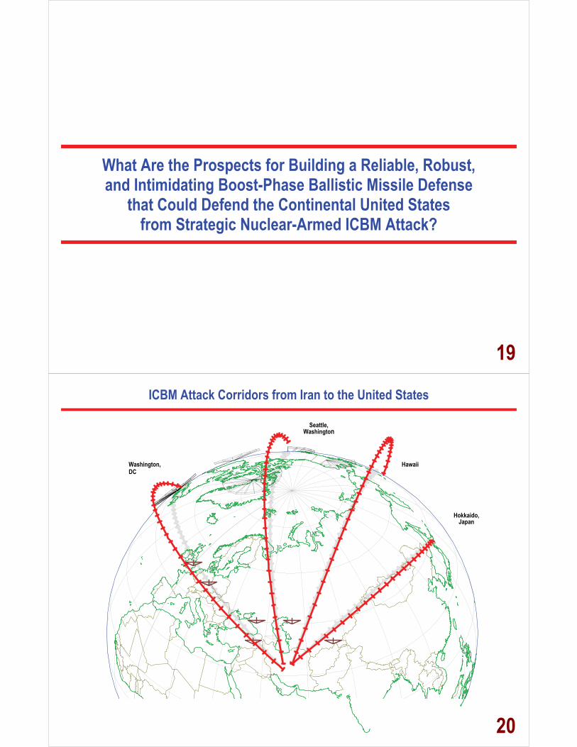
What Are the Prospects for Building a Reliable, Robust, and Intimidating Boost-Phase Ballistic Missile Defense
that Could Defend the Continental United States from Strategic Nuclear-Armed ICBM Attack?
19
ICBM Attack Corridors from Iran to the United States
Washington, DC
Hawaii
Seattle, Washington
Hokkaido, Japan
20

Coverage Against Unha-2 – Like Large Liquid Propellant with 240 Second + Burn is Possible
5 km/sec Interceptor, ~500 km range in about 100 seconds, Unha-2 Ballistic Missile gets to about 400 km in about 240 seconds
500 km in About 100 Seconds
400 km in About 240 Seconds
Third Stage Burn begins at About
240 seconds
21Coverage Against Unha-2 – Like Large Liquid Propellant
with 240 Second + Burn is Possible
500 km
Honolulu
Washington DC Chicago
San Francisco
Moscow
22
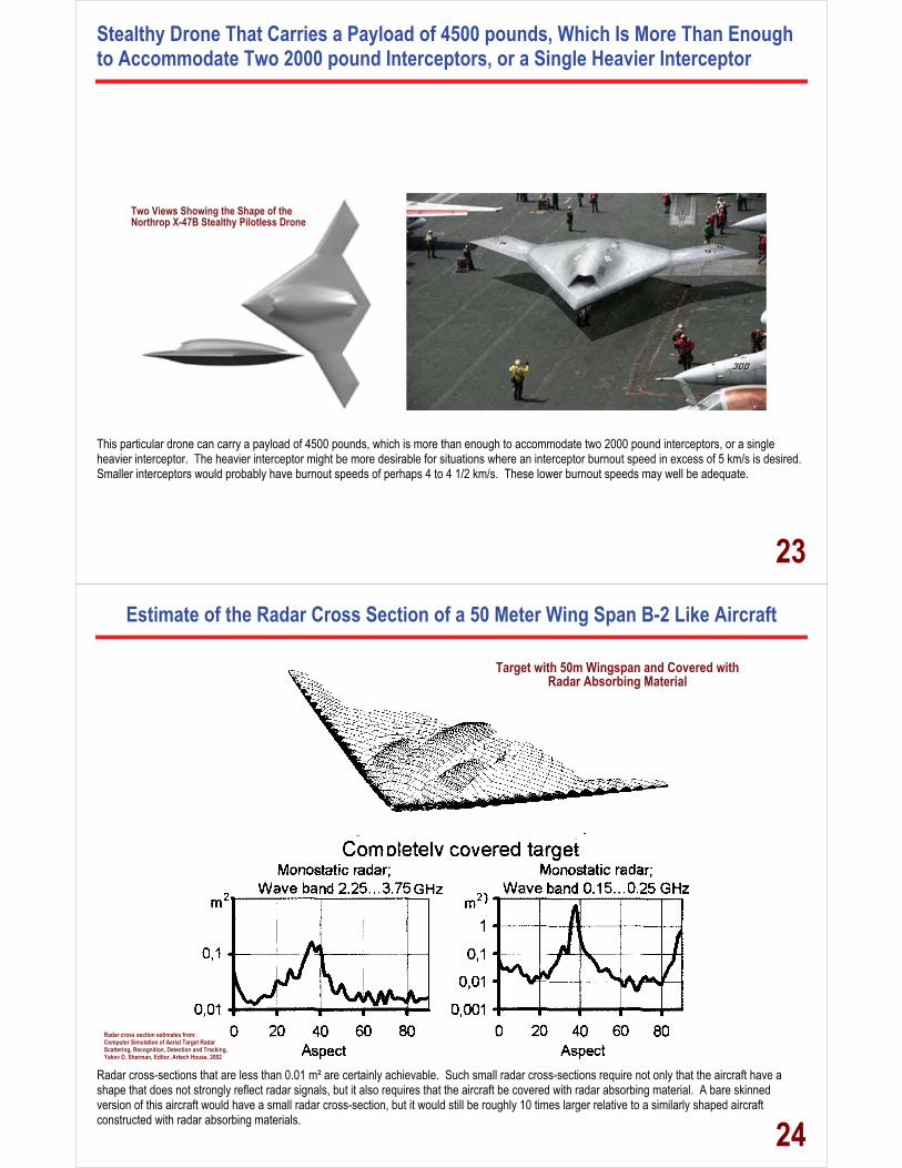
Stealthy Drone That Carries a Payload of 4500 pounds, Which Is More Than Enough to Accommodate Two 2000 pound Interceptors, or a Single Heavier Interceptor
This particular drone can carry a payload of 4500 pounds, which is more than enough to accommodate two 2000 pound interceptors, or a single heavier interceptor. The heavier interceptor might be more desirable for situations where an interceptor burnout speed in excess of 5 km/s is desired. Smaller interceptors would probably have burnout speeds of perhaps 4 to 4 1/2 km/s. These lower burnout speeds may well be adequate.
Two Views Showing the Shape of the Northrop X-47B Stealthy Pilotless Drone
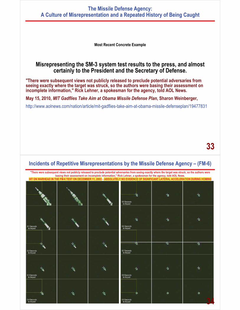
23Estimate of the Radar Cross Section of a 50 Meter Wing Span B-2 Like Aircraft
Radar cross-sections that are less than 0.01 m² are certainly achievable. Such small radar cross-sections require not only that the aircraft have a shape that does not strongly reflect radar signals, but it also requires that the aircraft be covered with radar absorbing material. A bare skinned version of this aircraft would have a small radar cross-section, but it would still be roughly 10 times larger relative to a similarly shaped aircraft constructed with radar absorbing materials.
Target with 50m Wingspan and Covered with Radar Absorbing Material
Radar cross section estimates from: Computer Simulation of Aerial Target Radar Scattering, Recognition, Detection and Tracking, Yakov D. Sherman, Editor, Artech House, 2002
24

Iran is a Large Country, But Not Large Enough to Make It Easy to Test Long Range Missiles
1640 kilometers
25Reports of Testing of the 2,000 Kilometer Range Sejjil-2 Ballistic Missile
on Lofted Trajectories Are Easily Explained If Iran Wants to Test Only Within Its National Boundaries
Examples of Test Trajectories that Can Be Flown by a 2,000 Kilometer Range Ballistic Missile
0 200 400 600 800 1000 1200 1400 1600 1800 20000
200
400
600
800
1000
1200
1400
Range (km)
Altitu
de (k
m)
4.11 km/sec Launch TrajectoriesLocations Shown at 10 second IntervalsMinimum Energy = 40.51 Deg1000 km Range = 61 Deg1500 km Range = 72 Deg1500 km Range = 21 Deg
Maximum Range
26

Iran’s Launch of a 27 Kilogram Satellite on February 2/3, 2009 Was Obviously Chosen to Not Overfly Adjacent Countries
SatelliteLocation
LaunchLocation
First Full OrbitLocation
27The First Stage of the Iran’s Satellite Launch Vehicle Fell Well Within Iran’s Borders
and the Second Stage Went Into Orbit with the Small Satellite
0 500 1000 1500 2000 2500 30000
500
1000
1500
2000Safir Satellite Launch Profile
Range (km)
Altitu
de (k
m)
Vehicle Locations Shown at 10 Second IntervalsSatellite Weight (kg) = 27Launch Gross Weight (kg) = 25,427First Stage Burn Time (sec) = 137Second Stage Burn Time (sec) = 274
Stage 1 Characteristics:Stage Full Weight (kg)) = 22,300Structure Factor = 0.1Stage Propellant Weight (kg) = 20,070Weight of Burned Fuel (kg) = 19,267Stage Empty Weight (kg) = 2230Stage Weight at Burnout (kg) = 3033Fraction of Fuel Unburned = 0.04Residual Unburned Fuel (kg) = 803Burn Time (sec) = 137
Stage 2 Characteristics:Stage Full Weight (kg) = 3100Structure Factor = 0.09Stage Propellant Weight (kg) = 2821Weight of Burned Fuel (kg) = 2736Stage Empty Weight (kg) = 279Stage Weight at Burnout (kg) = 364Fraction of Fuel Unburned = 0.03Residual Unburned Fuel (kg) = 85Burn Time (sec) = 274
Third Stage Burnout
Total Powered Flight Time (sec) = 411 (6 min, 51sec)
Second Stage Burnoutat 68 km Altitude
1.25 m
20,500 kgPropellant
Safir
First Stage Derivedfrom Nodong
Second StageDerived from SCUDThird Stage Derived
from SS-21
23.0 m
First Stage Derivedfrom NodongSecond Stage
Derived from R-27
1.25 m
Taepodong 1 28

Powered Flight Locations of a Titan II / SS-18 Class Liquid Propellant ICBM
0 100 200 300 400 500 600 700 8000
100
200
300
400
500Powered Flight Profile of Large Liquid Propellant ICBM
Range (km)
Altitu
de (k
m)
130140 145
60 seconds
180seconds
120 seconds
130 seconds
180 seconds
seconds120
140 seconds145 seconds
300seconds
Missile and Debris Locations Shown at 5 Second Intervals
29
Powered Flight Locations of a Titan II / SS-18 Class Liquid Propellant ICBM
0 500 1000 1500 2000 2500 3000 35000
500
1000
1500
2000
2500
Range (km)
Altitu
de (k
m)
Vehicle Locations Shown at 10 Second IntervalsUpper Stage + Payload Weight (kg) = 4000Launch Gross Weight (kg) = 91,600First Stage Burn Time (sec) = 118Second Stage Burn Time (sec) = 122
Expected and Actual Flight Outcomes Associated with theNorth Korean Satellite Launch Attempt of April 4/5, 2009
Second StageImpact Point
Stage 2 Characteristics:Stage Full Weight (kg) = 13550Structure Factor = 0.095Stage Propellant Weight (kg) = 12263Weight of Burned Fuel (kg) = 11895Stage Empty Weight (kg) = 1287Stage Weight at Burnout (kg) = 1655Fraction of Fuel Unburned = 0.03Residual Unburned Fuel (kg) = 368Burn Time (sec) = 122
Stage 3 Characteristics:Stage Full Weight (kg) = 3100Structure Factor = 0.09Stage Propellant Weight (kg) = 2821Weight of Burned Fuel (kg) = 2736Stage Empty Weight (kg) = 279Stage Weight at Burnout (kg) = 364Fraction of Fuel Unburned = 0.03Residual Unburned Fuel (kg) = 85Burn Time (sec) = 274
Third Stage Burn Time (sec) = 274Total Powered Flight Time (sec) = 514 (8 min, 34 sec)
Second StageBurnout
First StageImpact Point
Intended ThirdStage Burnout
Upper RocketStage
Satellite
Intended Third StagePowered Flight
Spent SecondStage CoastingTowards Impact
Intended SatelliteTrajectory
Stage 1 Characteristics:Stage Full Weight (kg)) = 74050Structure Factor = 0.08Stage Propellant Weight (kg) = 68126Weight of Burned Fuel (kg) = 65400Stage Empty Weight (kg) = 5924Stage Weight at Burnout (kg) = 8649Fraction of Fuel Unburned = 0.04Residual Unburned Fuel (kg) = 2725Burn Time (sec) = 117.6
First StageBurnout
30

Most Recent MDA Misrepresentation The SM-3 is a “Ballistic Missile Defense System [that] has
demonstrated 20 hit-to-kill intercepts [italics added] out of 24 at sea firing attempts.” **
** MDA Fact Sheet, November 24, 2009 09-MDA-5060
31
Results of SM-3 Flight Tests Derived from MDA’s Published Video Data
Results of U.S. Standard Missile 3 Flight Tests
32
The Missile Defense Agency: A Culture of Misrepresentation and a Repeated History of Being Caught
Most Recent Concrete Example
Misrepresenting the SM-3 system test results to the press, and almost certainly to the President and the Secretary of Defense.
"There were subsequent views not publicly released to preclude potential adversaries from seeing exactly where the target was struck, so the authors were basing their assessment on incomplete information," Rick Lehner, a spokesman for the agency, told AOL News. May 15, 2010, MIT Gadflies Take Aim at Obama Missile Defense Plan, Sharon Weinberger, http://www.aolnews.com/nation/article/mit-gadflies-take-aim-at-obama-missile-defenseplan/19477831
33
Incidents of Repetitive Misrepresentations by the Missile Defense Agency – (FM-6)
"There were subsequent views not publicly released to preclude potential adversaries from seeing exactly where the target was struck, so the authors were basing their assessment on incomplete information," Rick Lehner, a spokesman for the agency, told AOL News.
HIT ON WARHEAD IN THE FM-6 TEST ON DECEMBER 11, 2003 – ABSOLUTELY NO EVIDENCE OF SIGNIFICANT LATERAL ACCELERATION DURING HOMING
34

Credible Evidence of Repetitive Lying by the Missile Defense Agency – (FM-6)
"There were subsequent views not publicly released to preclude potential adversaries from seeing exactly where the target was struck, so the authors were basing their assessment on incomplete information," Rick Lehner, a spokesman for the agency, told AOL News.
HIT ON WARHEAD IN THE FM-6 TEST ON DECEMBER 11, 2003 – ABSOLUTELY NO EVIDENCE OF SIGNIFICANT LATERAL ACCELERATION DURING HOMING
35
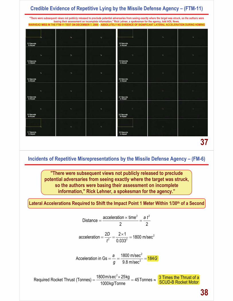
Credible Evidence of Repetitive Lying by the Missile Defense Agency – (FTM-11)
"There were subsequent views not publicly released to preclude potential adversaries from seeing exactly where the target was struck, so the authors were basing their assessment on incomplete information," Rick Lehner, a spokesman for the agency, told AOL News.
WARHEAD MISS IN THE FTM-11 TEST ON DECEMBER 7, 2006 – ABSOLUTELY NO EVIDENCE OF SIGNIFICANT LATERAL ACCELERATION DURING HOMING
36
Credible Evidence of Repetitive Lying by the Missile Defense Agency – (FTM-11)
"There were subsequent views not publicly released to preclude potential adversaries from seeing exactly where the target was struck, so the authors were basing their assessment on incomplete information," Rick Lehner, a spokesman for the agency, told AOL News.
WARHEAD MISS IN THE FTM-11 TEST ON DECEMBER 7, 2006 – ABSOLUTELY NO EVIDENCE OF SIGNIFICANT LATERAL ACCELERATION DURING HOMING
37
Incidents of Repetitive Misrepresentations by the Missile Defense Agency – (FM-6)
"There were subsequent views not publicly released to preclude potential adversaries from seeing exactly where the target was struck,
so the authors were basing their assessment on incomplete information," Rick Lehner, a spokesman for the agency.”
Lateral Accelerations Required to Shift the Impact Point 1 Meter Within 1/30th of a Second
2 2acceleration timeDistance
2 2a t�
� �
22 2
2 2 1acceleration 1800 m/sec0.033
Dt
�� � �
2
21800 m/secAcceleration in Gs 1849.8 m/sec
a Gg
� � �
21800m/sec 25kg 3 Times the Thrust of aRequired Rocket Thrust (Tonnes) 45Tonnes SCUD-B Rocket Motor1000kg/Tonne�
� � �
38
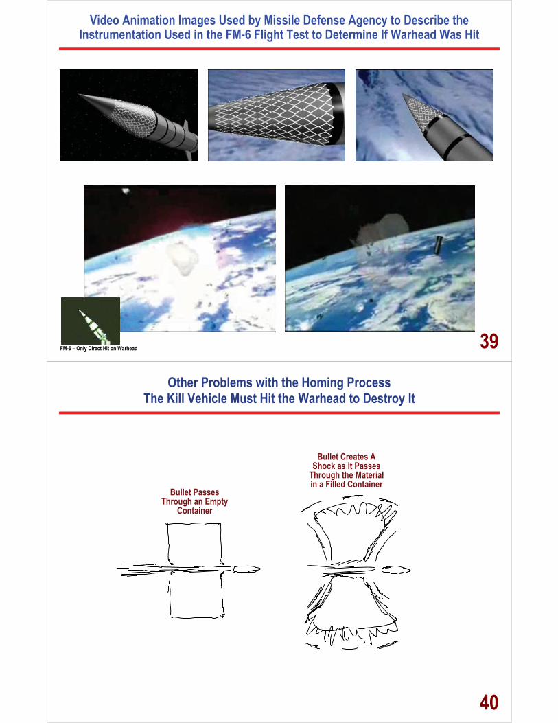
Video Animation Images Used by Missile Defense Agency to Describe the Instrumentation Used in the FM-6 Flight Test to Determine If Warhead Was Hit
FM-6 – Only Direct Hit on Warhead 39
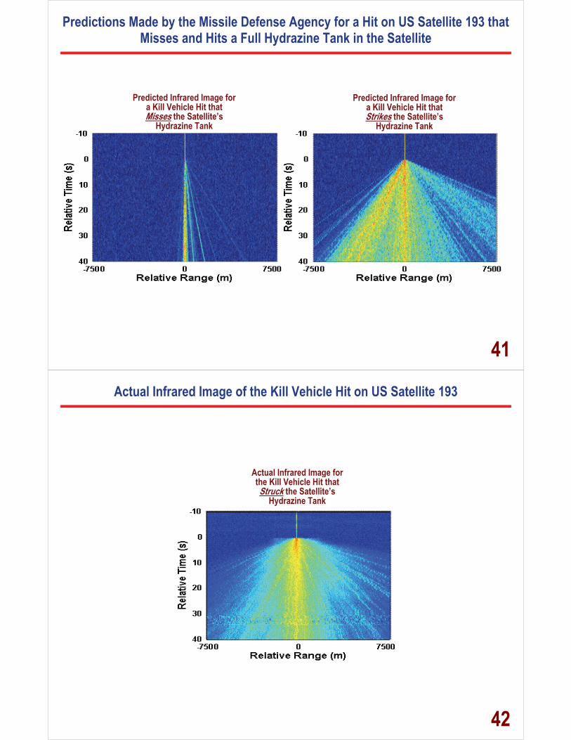
Other Problems with the Homing Process The Kill Vehicle Must Hit the Warhead to Destroy It
Bullet Passes Through an Empty
Container
Bullet Creates A Shock as It Passes
Through the Material in a Filled Container
40
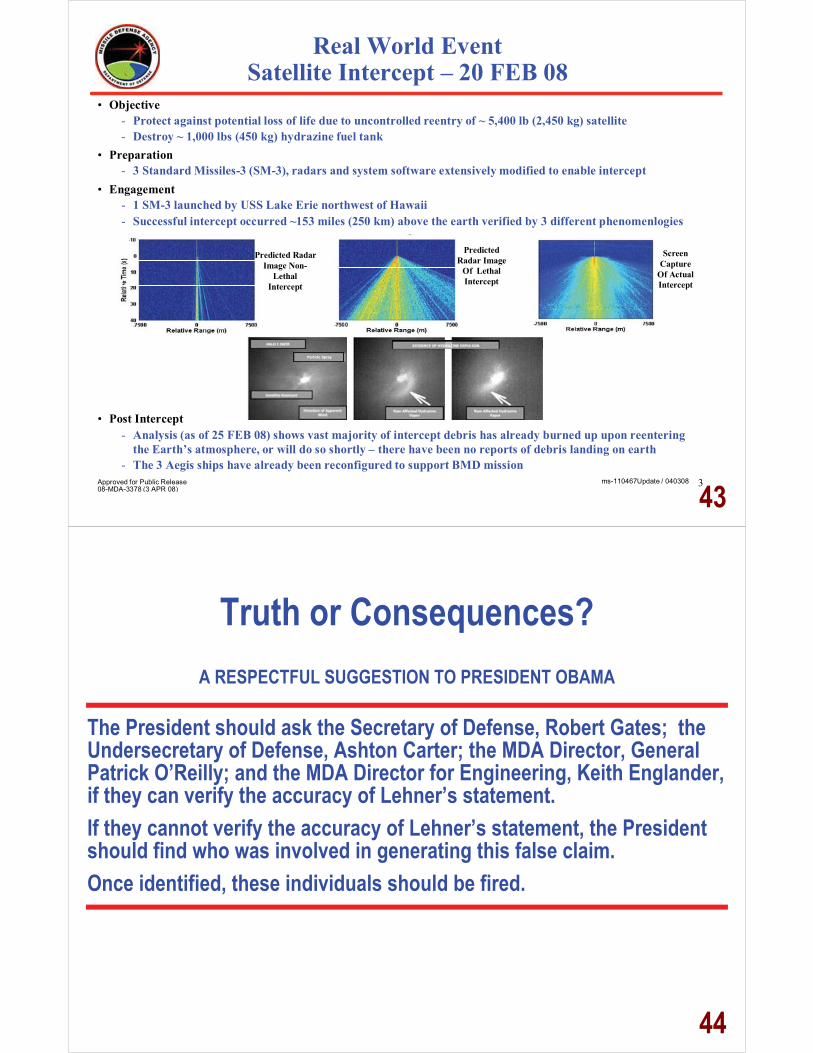
Predictions Made by the Missile Defense Agency for a Hit on US Satellite 193 that Misses and Hits a Full Hydrazine Tank in the Satellite
Predicted Infrared Image for a Kill Vehicle Hit that Misses the Satellite’s
Hydrazine Tank
Predicted Infrared Image for a Kill Vehicle Hit that Strikes the Satellite’s
Hydrazine Tank
41
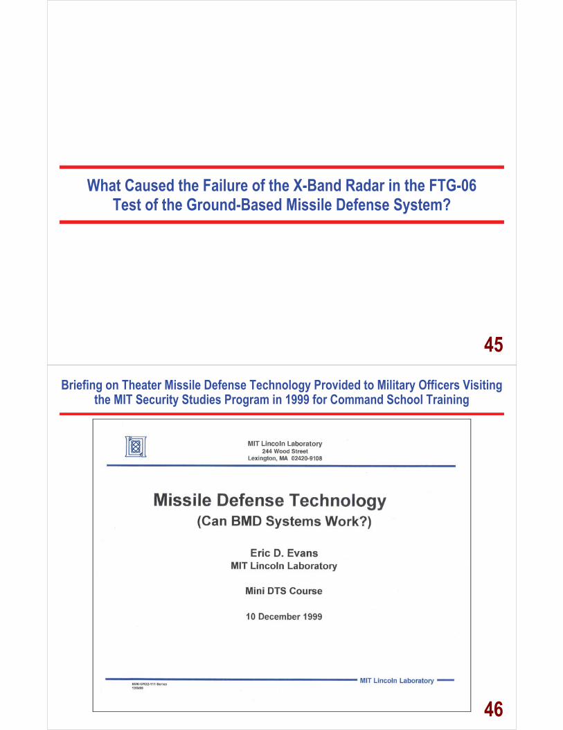
Actual Infrared Image of the Kill Vehicle Hit on US Satellite 193
Actual Infrared Image for the Kill Vehicle Hit that Struck the Satellite’s
Hydrazine Tank
42
Real World Event Satellite Intercept – 20 FEB 08
• Objective
- Protect against potential loss of life due to uncontrolled reentry of ~ 5,400 lb (2,450 kg) satellite - Destroy ~ 1,000 lbs (450 kg) hydrazine fuel tank
• Preparation - 3 Standard Missiles-3 (SM-3), radars and system software extensively modified to enable intercept
• Engagement - 1 SM-3 launched by USS Lake Erie northwest of Hawaii - Successful intercept occurred ~153 miles (250 km) above the earth verified by 3 different phenomenlogies
Predicted Radar Image Non-
Lethal Intercept
Predicted Radar Image
Of Lethal Intercept
Screen Capture
Of Actual Intercept
Particle Spray
• Post Intercept - Analysis (as of 25 FEB 08) shows vast majority of intercept debris has already burned up upon reentering
the Earth’s atmosphere, or will do so shortly – there have been no reports of debris landing on earth - The 3 Aegis ships have already been reconfigured to support BMD mission
Approved for Public Release 08-MDA-3378 (3 APR 08)
ms-110467Update / 040308 3
43
Truth or Consequences?
A RESPECTFUL SUGGESTION TO PRESIDENT OBAMA
The President should ask the Secretary of Defense, Robert Gates; the Undersecretary of Defense, Ashton Carter; the MDA Director, General Patrick O’Reilly; and the MDA Director for Engineering, Keith Englander, if they can verify the accuracy of Lehner’s statement. If they cannot verify the accuracy of Lehner’s statement, the President should find who was involved in generating this false claim. Once identified, these individuals should be fired.
44
What Caused the Failure of the X-Band Radar in the FTG-06 Test of the Ground-Based Missile Defense System?
45
Briefing on Theater Missile Defense Technology Provided to Military Officers Visiting the MIT Security Studies Program in 1999 for Command School Training
46
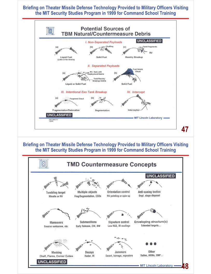
Briefing on Theater Missile Defense Technology Provided to Military Officers Visiting the MIT Security Studies Program in 1999 for Command School Training
47
Briefing on Theater Missile Defense Technology Provided to Military Officers Visiting the MIT Security Studies Program in 1999 for Command School Training
48

Briefing on Theater Missile Defense Technology Provided to Military Officers Visiting the MIT Security Studies Program in 1999 for Command School Training
49
Briefing on Theater Missile Defense Technology Provided to Military Officers Visiting the MIT Security Studies Program in 1999 for Command School Training
50
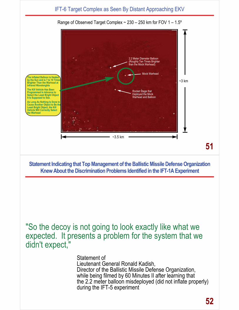
IFT-6 Target Complex as Seen By Distant Approaching EKV
Range of Observed Target Complex ~ 230 – 250 km for FOV 1 – 1.5º
~3.5 km
~3 km
2.2 Meter Diameter Balloon (Roughly Ten Times Brighter than the Mock Warhead)
Mock Warhead
Rocket Stage that Deployed the Mock Warhead and Balloon
The Inflated Balloon is Heated by the Sun and is 7 to 10 Times Brighter Than the Warhead at Infrared Wavelenghts The Kill Vehicle Has Been Programmed In Advance to Select the Least Bright Object It Is Supposed to See. As Long As Nothing Is Done to Cause Another Object to Be the Least Bright Object, the Kill Vehicle Will Correctly Select the Warhead
51
Statement Indicating that Top Management of the Ballistic Missile Defense Organization Knew About the Discrimination Problems Identified in the IFT-1A Experiment
"So the decoy is not going to look exactly like what we expected. It presents a problem for the system that we didn't expect,"
Statement of Lieutenant General Ronald Kadish, Director of the Ballistic Missile Defense Organization, while being filmed by 60 Minutes II after learning that the 2.2 meter balloon misdeployed (did not inflate properly) during the IFT-5 experiment
52

IFT-6 Target Complex as Seen By Distant Approaching EKV
Range of Observed Target Complex ~ 230 – 250 km for FOV 1 – 1.5º
~3.5 km
~3 km
2.2 Meter Diameter Balloon (Roughly Ten Times Brighter than the Mock Warhead)
Mock Warhead
Rocket Stage that Deployed the Mock Warhead and Balloon
In The IFT-5, The Balloon Failed to Inflate, So Only the Canister, Instead of the Hot Inflated Balloon, Would Have Been Observed By the Kill Vehicle. Since the Cannister Has a very Small Signal in the Infrared, It Is Now the Least Bright Object Observed by the Kill Vehicle Hence, The Kill Vehicle Would Now Select the Cannister as the Warhead
53
The Kill Vehicle Must Determine If a Ballon Contains a Warhead or If the Balloon Is Empty!
Balloons that Have Been Flown in Space
These Could Be Used as Decoys
or to Surround Warheads Disguising Them as Balloons
54

The Kill Vehicle Must Determine Which of These Are Warheads and Which are Decoys from 500 Kilometers Range!
55
Objects Flown in the IFT-1A and IFT-2 NMD Tests
LARGEBAL
SCLR
MEDBALA
MEDBALB
MEDRLR1
MEDRLR2
Large Balloon(2.2 Meter Diameter Balloon)
Small Canisterized Light Replica (Balloon)
Medium Rigid Light Replica 2(2 Meters Long & 0.6 Meter Base)
Medium Rigid Light Replica 1(2 Meters Long & 0.6 Meter Base)
Medium Balloon A(0.6 Meter Diameter Balloon)
Medium Balloon B(0.6 Meter Diameter Balloon)
MSLS
SCTBA
SCTBB
MRV
Mission Service Launch System(Rocket Upper Stage)
Small Cannisterized Traffic Balloon A(Small Balloon)
Small Cannisterized Traffic Balloon B(Small Balloon)
Medium Reentry Vehicle(2 Meters Long & 0.6 Meter Base)
56
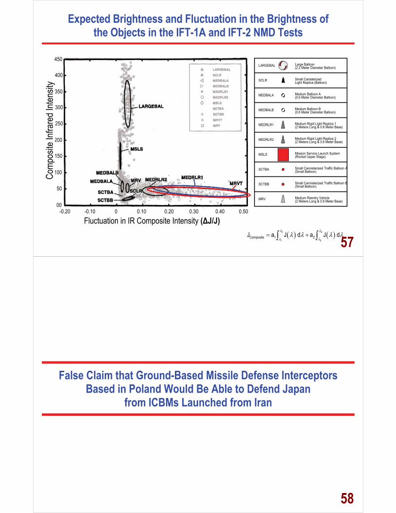
Expected Brightness and Fluctuation in the Brightness of the Objects in the IFT-1A and IFT-2 NMD Tests
-0.20 -0.10 0 0.10 0.20 0.30 0.40 0.50 Fluctuation in IR Signal Intensity (�J/J)
Infra
red I
ntens
ity
00
50
100
150
200
250
300
350
400
450 LARGEBAL
SCLR
MEDBALA
MEDBALB
MEDRLR1
MEDRLR2
MSLS
SCTBA
SCTBB
MRV
Large Balloon(2.2 Meter Diameter Balloon)
Small Canisterized Light Replica (Balloon)
Medium Rigid Light Replica 2(2 Meters Long & 0.6 Meter Base)
Medium Rigid Light Replica 1(2 Meters Long & 0.6 Meter Base)
Mission Service Launch System(Rocket Upper Stage)
Small Cannisterized Traffic Balloon A(Small Balloon)
Small Cannisterized Traffic Balloon B(Small Balloon)
Medium Reentry Vehicle(2 Meters Long & 0.6 Meter Base)
Medium Balloon A(0.6 Meter Diameter Balloon)
Medium Balloon B(0.6 Meter Diameter Balloon)
Fluctuation in IR Composite Intensity (�J/J)
Comp
osite
Infra
red I
ntens
ity
� � � �2 4
1 3Composite 1 2J a J d a J d
� � � 57
False Claim that Ground-Based Missile Defense Interceptors Based in Poland Would Be Able to Defend Japan
from ICBMs Launched from Iran
58
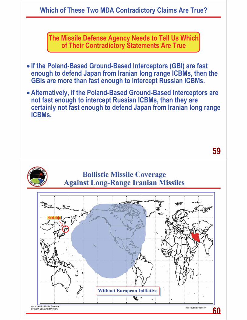
Which of These Two MDA Contradictory Claims Are True?
The Missile Defense Agency Needs to Tell Us Which of Their Contradictory Statements Are True
� If the Poland-Based Ground-Based Interceptors (GBI) are fast
enough to defend Japan from Iranian long range ICBMs, then the GBIs are more than fast enough to intercept Russian ICBMs.
� Alternatively, if the Poland-Based Ground-Based Interceptors are not fast enough to intercept Russian ICBMs, than they are certainly not fast enough to defend Japan from Iranian long range ICBMs.
59
Hokkaido
60

Hokkaido
61
Missile Defense Agency Slides Showing Additional Defense-Coverage of Hokkaido, Japan with Interceptors from the Polish Launch Site
Relevant Observations: � Radar in Czech Republic Not Used � Intercept Achieved with FBX
or Adjunct Radar Tracking from Eastern Turkey � Interceptor Speed 40% Faster Than 6.3 km/sec
Speed Claimed by US administration � HOWEVER, MDA CONTINUES TO REVISE AND
CHANGE ITS STATEMENTS ABOUT THE CHARACTERISTICS OF THE POLISH-BASED INTERCEPTORS
62
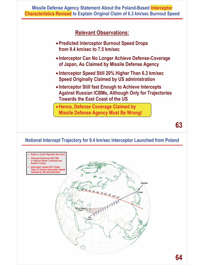
Missile Defense Agency Statement About the Poland-Based Interceptor Characteristics Revised to Explain Original Claim of 6.3 km/sec Burnout Speed
Relevant Observations:
� Predicted Interceptor Burnout Speed Drops from 9.4 km/sec to 7.5 km/sec
� Interceptor Can No Longer Achieve Defense-Coverage of Japan, As Claimed by Missile Defense Agency
� Interceptor Speed Still 20% Higher Than 6.3 km/sec Speed Originally Claimed by US administration
� Interceptor Still fast Enough to Achieve Intercepts Against Russian ICBMs, Although Only for Trajectories Towards the East Coast of the US
� Hence, Defense Coverage Claimed by Missile Defense Agency Must Be Wrong!
63
Notional Intercept Trajectory for 9.4 km/sec Interceptor Launched from Poland
2.5 3.55.54.5
7.56.59.58.5
11.5 10.5
0 2 1
4 3
6 5
8 7
10 9 11
FBX or AdjunctRadar
Iran Launch
Target
� Radar in Czech Republic Not Used � Intercept Achieved with FBX
or Adjunct Radar Tracking from Eastern Turkey
� Interceptor Speed 40% Faster Than 6.3 km/sec Interceptor Speed Claimed by US administration
Hokkaido
64

Revised Interceptor Characteristics Indicates Defense-Coverage Claimed by Missile Defense Agency Must Be Wrong!
2.53.5 5.5
4.5
7.56.5
9.58.5
11.5
10.5
0 2 1
4 3
6 5
8 7
10 9 11
FBX or AdjunctRadar
Iran Launch
Target
� Radar in Czech Republic Not Used � Intercept Achieved with FBX
or Adjunct Radar Tracking from Eastern Turkey
� REVISED MDA Interceptor Parametrs Give Burnout Speed of 7.5 km/sec, 15% Faster Than Originally Claimed by MDA Spokesman and Chief Scientist!
Hokkaido Intercept
NOT POSSIBLE!
65
Hokkaido
BMD System W/Interceptor Field (Poland) + Midcourse Radar (Czech Republic) + Forward Based Radar
NO STATEMENT ON MDA SLIDE THAT
SAYS HOKKAIDO CAN BE DEFENDED WITH
INTERCEPTORS FROM ALASKA!
66
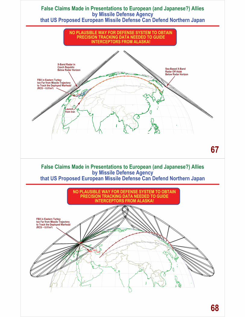
False Claims Made in Presentations to European (and Japanese?) Allies by Missile Defense Agency
that US Proposed European Missile Defense Can Defend Northern Japan
FBX in Eastern Turkey too Far from Missile Trajectory to Track the Deployed Warhead (RCS ~ 0.01m2)
X-Band Radar in Czech Republic Below Radar Horizon Sea-Based X-Band
Radar Off Adak Below Radar Horizon
Launch from Iran
NO PLAUSIBLE WAY FOR DEFENSE SYSTEM TO OBTAIN PRECISION TRACKING DATA NEEDED TO GUIDE
INTERCEPTORS FROM ALASKA!
67False Claims Made in Presentations to European (and Japanese?) Allies
by Missile Defense Agency that US Proposed European Missile Defense Can Defend Northern Japan
FBX in Eastern Turkey too Far from Missile Trajectory to Track the Deployed Warhead (RCS ~ 0.01m2)
NO PLAUSIBLE WAY FOR DEFENSE SYSTEM TO OBTAIN PRECISION TRACKING DATA NEEDED TO GUIDE
INTERCEPTORS FROM ALASKA!
68
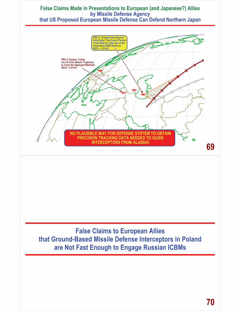
False Claims Made in Presentations to European (and Japanese?) Allies by Missile Defense Agency
that US Proposed European Missile Defense Can Defend Northern Japan
FBX in Eastern Turkey too Far from Missile Trajectory to Track the Deployed Warhead (RCS ~ 0.01m2)
FBX in “Caspian-Sea Region”Only Radar That Could Provide Track Data for Intercept of the Postulated ICBM Warhead (RCS ~ 0.01m2)
NO PLAUSIBLE WAY FOR DEFENSE SYSTEM TO OBTAIN PRECISION TRACKING DATA NEEDED TO GUIDE
INTERCEPTORS FROM ALASKA! 69
False Claims to European Allies that Ground-Based Missile Defense Interceptors in Poland
are Not Fast Enough to Engage Russian ICBMs
70

Which of These Two MDA Contradictory Claims Are True?
The Missile Defense Agency Needs to Tell Us Which of Their Contradictory Statements Are True
� If the Poland-Based Ground-Based Interceptors (GBI) are fast
enough to defend Japan from Iranian long range ICBMs, then the GBIs are more than fast enough to intercept Russian ICBMs.
� Alternatively, if the Poland-Based Ground-Based Interceptors are not fast enough to intercept Russian ICBMs, than they are certainly not fast enough to defend Japan from Iranian long range ICBMs.
71
72

73
Engagement Event Timeline for Engagement of SS-25 from Vypolzovo with 2-Stage Missile Defense Interceptor
T=170 secEnd of SS-25 Powered Flight, Also Point of Radar Acquisition
T=0 minutes Interceptor Launch
T=0 minutesInterceptor Launch
T=1 minutesT=2 minutes
T=1.7 minutes Interceptor Burnout
T=50 secInfrared Satellite Detection C l t
T=0 sec Launch Transient Detection? C l t
T=500 sec Interceptor and warhead Collide
INTERCEPT!T=5 minutes
2 minutes
3 minutes
4 minutes
5 minutes
T=3 minutesT=4 minutes
74
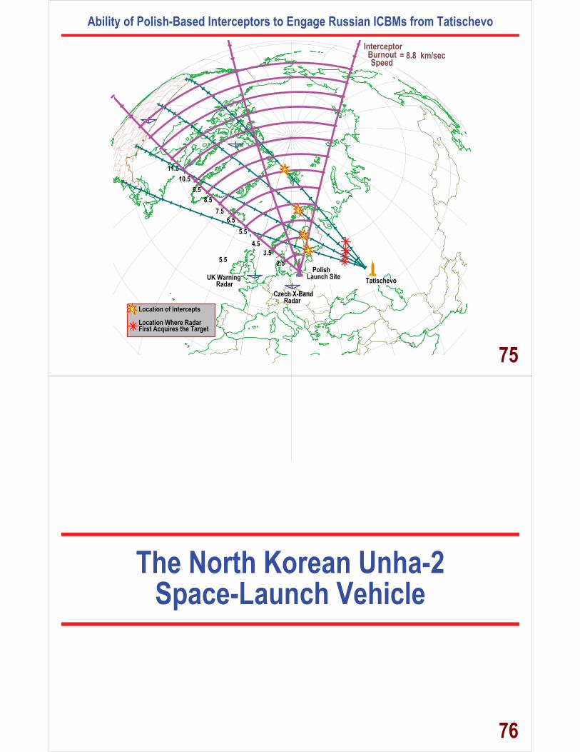
Ability of Polish-Based Interceptors to Engage Russian ICBMs from Tatischevo
TatischevoLaunch SitePolish
Czech X-BandRadar
UK WarningRadar
5.5 2.53.5
4.5
7.5
9.510.5
11.5
8.5
Location of Intercepts
Location Where RadarFirst Acquires the Target
6.5
Burnout Interceptor
Speed = 8.8 km/sec
5.5
75
The North Korean Unha-2 Space-Launch Vehicle
76

The Evolution of Iranian and North Korean Rocket Vehicles
16.5 m
12,400 kgPropellant
4,300 kgPropellant
3,786 kgPropellant
14,900 kgPropellant
20,500 kgPropellant
15.5 m
10.9 m10.9 m
Shahab-1 Shahab-2 Shahab-3 Shahab-3M0.88 m 1.25 m
SCUD-B SCUD-C Nodong Derived fromNodong
First Stage Derivedfrom Nodong
Second StageIndigenous
3,786 kg PropellantPropellant Density 1252.5 kg/m3Oxidizer to Fuel Volume =1.83Oxidizer to Fuel Weight =3.4Actual Propellant Density=1326.6 kg/m30.944 of Fuel Tank Volume Filled
SCUD-B
5.5
10.4
1.25 m
22 m
14.0974
3,375 kg fuelfor 298 sec burn and3% residual fuel
2.7
1.25 m
1.50 m
29.86 m
4.14
6.64 m
16.06 m
13.57 m69,000 kgPropellant
Denstiy1,223 kg/m3Full Weight75,000 kgResidual
0.03Structure
.080
12,260 kgPropellantFull Weight13,550 kgResidual
0.03Structure
.095Range
2500 km
0.60
2.40
2.9541
1.3922
First Stage Uses Clusterof Four Nodong Motors
Second Stage is an SS-N-6Third-Stage Same as the
Second Stage from the Safir SLV
2.40 m
First Stage Derivedfrom NodongSecond Stage
Derived from SCUDand SA-5
Third Stage Derivedfrom SS-21
1.25 m
9.6901
25.0049
5.5000
Safir SLV Taepodong-1 Unha-2
10.2
77Video Frames Showing the Initial Acceleration at Launch of the Unha-2
Time After Launch:0 seconds
Time After Launch: 2.27 seconds
Time After Launch: 3.00 seconds 78

Apparent Mock Up of Cluster of Four Nodong Rocket Motors Displayed by Iran, Possibly Replicating Motor Assembly from the North Korean Unha-2 First Stage
Source: Composite of two video frames constructed from http://www.youtube.com/watch?v=nZoNdf6hlII&feature=player_embedded#
79Observed Acceleration at Launch of the Unha-2
0 0.5 1 1.5 2 2.5 3 3.5 4 4.5 50
5
10
15
20
25
30
35
40
45
Time After Launch (sec)
Dista
nce M
oved
(m)
Unha-2 Launch Vehicle
Acceleration Rate = 0.34483 Gs
80

Estimated Dimensions of the Unha-2 Launch Vehicle
1.25
1.50
2.40
29.86
4.14
6.64
16.06
13.5769,000 kgPropellant
12,260 kgPropellantFull Weight13,550 kgResidual
0.03Structure
.095Range
2500 km
81Rocket Components that Might Have Been Used to Construct the North Korean Unha-2
2.40
1.25
1.50
SS-N-6(R-27)
29.86
4.14
6.64
16.06
13.5769,000 kgPropellant
Denstiy1,223 kg/m3Full Weight75,000 kgResidual
0.03Structure
.080
12,260 kgPropellantFull Weight13,550 kgResidual
0.03Structure
.095Range
2500 km
12.36
0.60
1.39
7.54
3.53
2.40
Iranian / North KoreanSafir Second Stage
1.251.50 1.25 m
First Stage Derivedfrom Nodong
Second StageIndigenous
22 m
Iranian / SafirSatellite Launch Vehicle
9.65
9.65
82

North Korean Satellite Launch of April 4/5, 2009
0 500 1000 1500 2000 2500 3000 35000
500
1000
1500
2000
2500
Range (km)
Altitu
de (k
m)Vehicle Locations Shown at 10 Second IntervalsUpper Stage + Payload Weight (kg) = 4000Launch Gross Weight (kg) = 91,600First Stage Burn Time (sec) = 118Second Stage Burn Time (sec) = 122
Expected and Actual Flight Outcomes Associated with theNorth Korean Satellite Launch Attempt of April 4/5, 2009
Second StageImpact Point
Stage 2 Characteristics:Stage Full Weight (kg) = 13550Structure Factor = 0.095Stage Propellant Weight (kg) = 12263Weight of Burned Fuel (kg) = 11895Stage Empty Weight (kg) = 1287Stage Weight at Burnout (kg) = 1655Fraction of Fuel Unburned = 0.03Residual Unburned Fuel (kg) = 368Burn Time (sec) = 122
Stage 3 Characteristics:Stage Full Weight (kg) = 3100Structure Factor = 0.09Stage Propellant Weight (kg) = 2821Weight of Burned Fuel (kg) = 2736Stage Empty Weight (kg) = 279Stage Weight at Burnout (kg) = 364Fraction of Fuel Unburned = 0.03Residual Unburned Fuel (kg) = 85Burn Time (sec) = 274
Third Stage Burn Time (sec) = 274Total Powered Flight Time (sec) = 514 (8 min, 34 sec)
Second StageBurnout
Second StageImpact Point
Intended ThirdStage Burnout
Upper RocketStage
Satellite
Intended Third StagePowered Flight
Spent SecondStage CoastingTowards Impact
Intended SatelliteTrajectory
Stage 1 Characteristics:Stage Full Weight (kg)) = 74050Structure Factor = 0.08Stage Propellant Weight (kg) = 68126Weight of Burned Fuel (kg) = 65400Stage Empty Weight (kg) = 5924Stage Weight at Burnout (kg) = 8649Fraction of Fuel Unburned = 0.04Residual Unburned Fuel (kg) = 2725Burn Time (sec) = 117.6
First StageBurnout
83Announced Safety Keep-Out Zones for the North Korean Satellite Launch of April 4/5, 2009
First Stage Impact Range = 500 to 700 km
Second Stage Impact Range = 3,150 to 4,000 km
First Stage Impact Area
Second Stage Impact Area
84
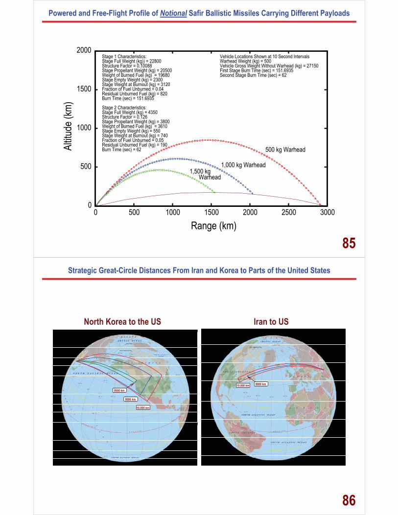
Powered and Free-Flight Profile of Notional Safir Ballistic Missiles Carrying Different Payloads
0 500 1000 1500 2000 2500 30000
500
1000
1500
2000
Range (km)
Altitu
de (k
m)Vehicle Locations Shown at 10 Second IntervalsWarhead Weight (kg) = 500Vehicle Gross Weight Without Warhead (kg) = 27150First Stage Burn Time (sec) = 151.6935Second Stage Burn Time (sec) = 62
Stage 1 Characteristics:Stage Full Weight (kg)) = 22800Structure Factor = 0.10088Stage Propellant Weight (kg) = 20500Weight of Burned Fuel (kg) = 19680Stage Empty Weight (kg) = 2300Stage Weight at Burnout (kg) = 3120Fraction of Fuel Unburned = 0.04Residual Unburned Fuel (kg) = 820Burn Time (sec) = 151.6935
Stage 2 Characteristics:Stage Full Weight (kg) = 4350Structure Factor = 0.126Stage Propellant Weight (kg) = 3800Weight of Burned Fuel (kg) = 3610Stage Empty Weight (kg) = 550Stage Weight at Burnout (kg) = 740Fraction of Fuel Unburned = 0.05Residual Unburned Fuel (kg) = 190Burn Time (sec) = 62 500 kg Warhead
1,000 kg Warhead1,500 kg
Warhead
85
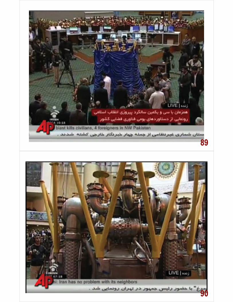
Strategic Great-Circle Distances From Iran and Korea to Parts of the United States
North Korea to the US Iran to US
9000 km
10,000 km
8000 km
10,000 km 9000 km
86

Range-Payload Capabilities of Two and Three Stage Variants of the North Korean Unha-2
2000 3000 4000 5000 6000 7000 8000 9000 10000 11000 12000
400
600
800
1000
1200
1400
1600
1800
2000
Range (km)
Paylo
ad (k
g)
2-Stage Unha-2Upper Stage Based onNodong Technology
Upper Stage Based onSS-N-6 Technology
Anchorage, Alaska~1800 kg
Seattle, Washington~1300 kg
San Francisco, California~1200 kg
Range versus Payload of Two and Three-Stage Unha-2 Variants
~700 kg
~900 kg
~1600 kg 3-Stage Unha-2
3rd Stage StructureFactor=0.15
3rd Stage StructureFactor=0.13
2-Stage Unha-2Upper Stage Based on
SS-N-6 Technology
Washington, DC~1000 kg
87Range Versus Payload for Iranian and North Korean Ballistic Missiles
SCUD-B
SCUD-C
Shahab-3 Safir
0 2000 4000 6000 8000 10000 12000
400
600
800
1000
1200
1400
1600
1800
2000
Range (km)
Paylo
ad (k
g)
Range Versus Payload of Two and Three Stage Taepodong-2 Ballistic Missilesand the SCUD-B, SCUD-C, Shahab-3 and Shahab-3M, and Safir
Two-Stage Unha-2Upper Stage Based onSS-N-6 Rocket SLBM
Upper Stage Based onSCUD Technology
Shahab-3M
SafirUpper Stage Based on
Advanced Rocket Stage
SCUD Technology
Two-Stage Taepodong-2Second Stage Based on
Three-Stage Taepodong-2Second and Third Stage Based on
SCUD Technology
Three-Stage Unha-2Second Stage Based on
SS-N-6 Rocket SLBMThird Stage Based on
SCUD-B or SA-5 Rocket Motor
88
89
90
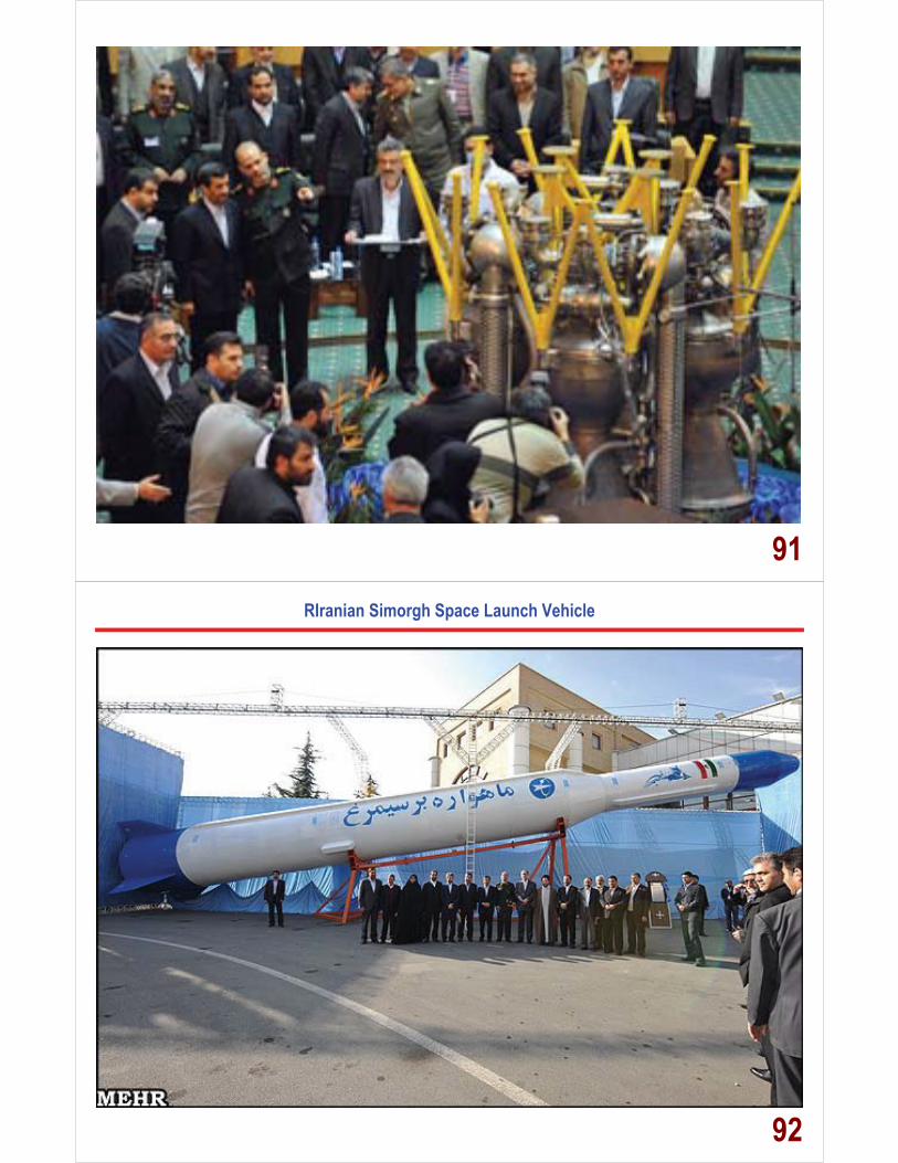
91RIranian Simorgh Space Launch Vehicle
92
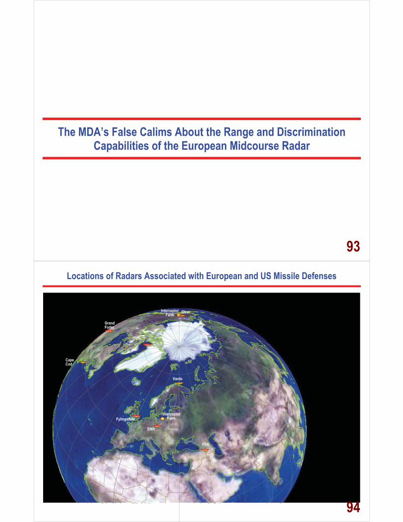
The MDA’s False Calims About the Range and Discrimination Capabilities of the European Midcourse Radar
93
Locations of Radars Associated with European and US Missile Defenses
EMR
Fylingsdale
Vardo
Grand Forks
Clear
Thule
Cape Cod
FBX
Interceptor Farm
Interceptor Farm
94

Radar-Range Fans for US Proposed EMR and FBX Missile Defense Radars
EMR
Fylingsdale
Vardo
Grand Forks
Clear
Thule
Locations of Postulated ICBMs Launched from Iran
to the Continental United States at One Minute Intervals
Range-Fan for S/N=100and RCS=1.00 m2
Range-Fan for S/N=100and RCS=0.01 m2
Range-Fan for S/N=100 and RCS=0.01 m2
Range-Fan for S/N=100and RCS=1.00 m2
Cape Cod
1 m2 RCS
0.01 m2
RCS
95
Radar-Range Fans for Vardo and US Proposed EMR and FBX Missile Defense Radars
Grand Forks
Clear
Range-Fan for S/N=1000.10 seconds Integration
and RCS=0.01 m2
Range-Fan for S/N=100with One Pulse
and RCS=0.01 m2
Range-Fan for S/N=100 0.10 seconds Integration
and RCS=0.01 m2
EMR
Thule
EMR
FBX
Vardo
Fylingsdale
96

Radar-Range Fans for Vardo and US Proposed EMR and FBX Missile Defense Radars
Cape Cod
Grand Forks
Clear
Locations of ICBM
EMR Line-of Sight
Fylingsdale Line-of Sight
Thule Line-of Sight
Cape Cod Line-of Sight
Locations of Postulated ICBMs Launched from Iran
to the Continental United States at One Minute Intervals
Fylingsdale Tracking
Thule Tracking
Fylingsdale Tracking
Thule Tracking
EMR Tracking
Cape Cod Tracking
Vardo Line-of Sight
Vardo Tracking Vardo Tracking
EMR Tracking
Range-Fan for S/N=1000.10 seconds Integration
and RCS=0.01 m2
Range-Fan for S/N=100with One Pulse
and RCS=0.01 m2
Range-Fan for S/N=100 0.10 seconds Integration
and RCS=0.01 m2
EMR
Thule
EMR
FBX
Vardo
Fylingsdale
97
Discrimination Ranges that Could Actually be ACHIEVED by the EMR and FBX Radars
EMR
Fylingsdale
Vardo
Grand Forks
Clear
Thule
Locations of Postulated Ballistic Missiles Launched from Iran to Europe
and the Continental United States at One Minute Intervals
Range-Fan for S/N=100and RCS=0.01 m2
Range-Fan for S/N=100 and RCS=0.01 m2
Cape Cod
Chicago
Helsinki
98
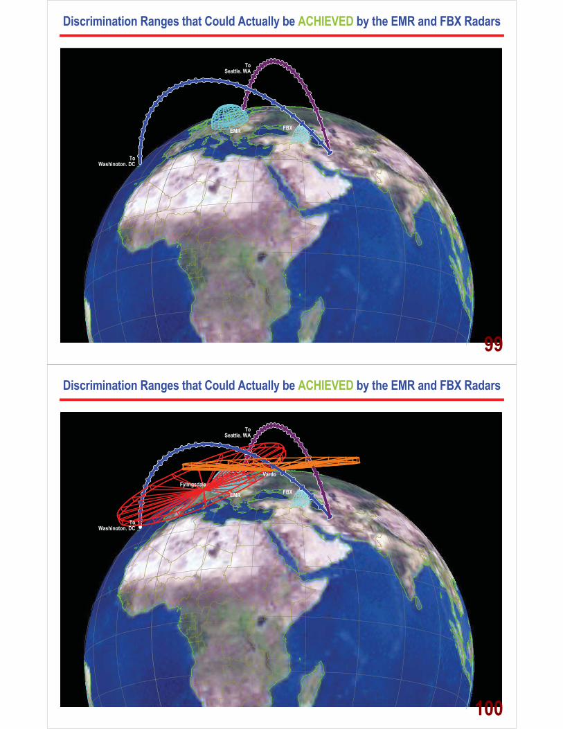
Discrimination Ranges that Could Actually be ACHIEVED by the EMR and FBX Radars
To Washington, DC
To Seattle, WA
EMR FBX
99
Discrimination Ranges that Could Actually be ACHIEVED by the EMR and FBX Radars
To Washington, DC
To Seattle, WA
EMR FBX Fylingsdale
Vardo
100

Ground-Based Interceptor: Missile Defense Agency Claims It Achieves 6.3 km/sec Carrying a Payload of 120 – 130 kg, Pegasus Parameters Indicate a
6.3 km/sec Burnout Speed with a Roughly 900 – 1000 kg Payload
Orbital Sciences GBI
101
Evolution and Comparison of Launch Vehicles, ICBMs and the GBI Interceptor
Pegasus OrbitalLauncher
Pegasus OrbitalLauncher
Three StageGBI
Two Stage GBI withPegasus Shroud
Comparison ofMinuteman III andPegasus Shroud
Two Stage GBI withMinuteman III Shroud
Minuteman IIIWarhead
Minuteman IIIMidgetman
ICBMBoeing GBI
Pegasus Evolution GBI Evolution ICBMs
Boeing GBI
Launch Weight with 155 lb EKV = 47,655 lbs
Launch Weight with 132 lb EKV = 31,473 lbs
30,000 lbs 75,000 lbs
102

Ground-Based Interceptor Achieves 8.5 to 8.7 km/sec Carrying a Payload of 220 to 155 lbs
Midgetman ICBM
Orbital Sciences GBI
The GBI Has a Higher Lift Capability than the US Midgetman ICBM!
103
The Ground-Based Interceptor Can Carry a Full Minuteman III BUS and Three Warheads to 6,000+ Kilometers
Orbital Sciences GBI Minuteman Shroud,
Warheads, and BUS
104

False Claims to European Allies About the “Theoretical” Capabilities of the Europe-Based Missile Defense Components
105
Engagement With Russia • March 17, 2006 (Washington): Bilateral Defense Commission Meeting. Under Secretary of Defense Edelman and General Mazurkevich, Chief of the Main Directorate for International Cooperation
• April 3, 2006 (Moscow): Briefing of Russian officials by U.S. Embassy (Moscow) on DOD decision to resume consultations with Poland regarding the site of U.S. missile defense assets
• November 3, 2006 (Moscow): Dr. Cambone, Lt Gen Obering, DASD Green, Russian Minister of Defense Ivanov, Chief of General Staff Gen-Col Baluevskiy, Gen-Col Mazurkevich - Russians did not acknowledge Iran emerging threat as a rationale for deployment of U.S. missile defense assets
- Believe Russia is real target - Russians “portrayed” lack of understanding and confusion on technical aspects of a
deployed missile program and proposed architecture. U.S. committed to following-up with technical discussions to Russian counterparts
• January 29, 2007 (Moscow): Strategic Dialogue Meeting. Under Secretaries Joseph and Deputy Foreign Minister Kislyak
- Ambassador re-committed that U.S. will follow-up with technical briefings/explanations regarding U.S. missile deployment
• February 9, 2007 (Seville): Secretary Gates and Minister of Defense Ivanov during NATO- Russia Council Ministerial meeting
U.S. Has Offered Future Event Establishing Technical Experts Meeting (Spring 2007)
Concerns Expressed by the Russians
106

The interceptors planned for Poland are nearly identical to the three-stage interceptors based in the U.S. except that they are a two-stage variant that is quick- er, lighter, and better suited for the engagement ranges and
EKV
timelines for Europe. The silos that house the ground-based intercep- tors have substantially smaller dimensions (e.g., diameter and length) than those used for offensive missiles, such as the U.S. Minuteman III ICBM. Any modification would require extensive, lengthy, and costly changes that would be clearly visible to any observer.
The ground-based interceptors are comprised of a booster vehicle and an exoatmospheric kill vehicle (EKV). Upon launch, the boost- er flies to a projected intercept point and releases the EKV which then uses on-board sensors (with assistance from ground-based as- sets) to acquire the target ballistic missile. The EKV performs final discrimination and steers itself to collide with the enemy warhead, destroying it by the sheer kinetic force of impact.
Future European Missile Site – Size Comparison
4
Interceptors are Modified Ground-Based Interceptors
2 Stage Instead of 3 Stage 47,385 lbs versus 49,150 lbs Both variants are 51 Feet Long
107
The Constantly Changing Stories from the Missile Defense Agency
(1 of 2)
Technical Properties of the Poland-Based Two-Stage Interceptors Four Contradictory Sets of Characteristics Describing the Performance of the Ground-Based Interceptor
1. Burnout Speed = 6.3 km/sec 2. Stage Full and Empty Weights Provided to the Associated Press by Colonel
Rick Lehner, Spokesman for the Missile Defense Agency. 3. Full and Empty Weights Plus ISP for Stages 1 and 2 in “Response to Postol”
(Still Gives 7.5 km/sec Interceptor! – Interceptor Upper Stage Loses 600 lbs of Propellant Relative to Commercial Rocket, Motor casing Becomes 600 lbs Heavier, Lower Rocket Stage Motors 5% Less Efficient Than Commercial Version)
4. Full and Empty Weights Plus ISP for Stages 1 and 2 from Taurus and Pegasus Commercial User’s Manuals Gives 8.9 km/sec Interceptor Burnout Speed.
108

The Constantly Changing Stories from the Missile Defense Agency
(2 of 2)
Multiple and Changing Explanations of How Defended Areas Are Expanded by the Addition of European Defense Components
(EMR in Czech Republic, Two-Stage Interceptors in Poland, and FBX at Unspecified Location) 1. Addition of Interceptors in Poland Makes It Possible to Defend Hokkaido, Japan! 2. 6.3 km/sec Interceptor Not Fast Enough to Defend Hokkaido!
(Roughly 9 km/sec is Needed). 3. Czech Radar Could Play No Role in Defense of Hokkaido! 4. Alaska Radars Could Play No Role in Defense of Hokkaido! 5. Postol “Misinterpreted” Missile Defense Agency Slides!
Interceptors from Alaska Are Used to Defend Hokkaido! 6. Forward-Based X-Band Radar Might Be Able to Provide Tracking for Interceptors If It
Is Deployed in the Caspian Sea !
109
Details Associated with the Contradictions and False Claims
Being Made By the US Missile Defense Agency About the Two-Stage Poland-Based Interceptor
110

Data from Press Statements by Spokesman and Chief Scientist for the Missile Defense Agency, Colonel Rick Lehner and Mr. Keith Englander
Provided Stage Weights for the Orbital Sciences Two-Stage Ground-Based Interceptor
STATEMENTS MADE BY MDA TO THE PRESS: Launch Weight = 47,400 lbs First Stage Weight = 37,800 lbs Second Stage Weight = 9,500 lbs Kill Vehicle Weight = 155 lbs Burnout Speed = 6.3 km/sec
ANALYTIC RESULTS: � Assumptions:
The shroud weighs 200 lbs, and the Pegasus-derived rocket motor fuel weights and specific impulses are exactly those from the AIAA International Reference Guide to Space Launch Systems.
� Expected Launch Weight of GBI = 37,800 + 9,500 + 155 + 200 = 47, 655 lbs. � The vehicle weight stated by Lehner is 47,400 lbs) � If one assumes a vehicle with a Launch Weight of 49,730 lbs, a payload of 2075 + 155 = 2230lbs,
the burnout speed is 6.30 km/sec. � The same vehicle carrying a 155 lb payload achieves a burnout speed of 9.37 km/sec. � If the vehicle payload is 255 lbs, to accommodate a 100 lb vibration isolation and mounting adapter,
(and/or endo/exo heatshield protection for EKV) the burnout speed is then 9.11 km/sec
CONCLUSION US Interceptors will have sufficient speed to engage all Russian ICBMs launched from West of the Urals against all targets in the continental United States
111
Data on Ground-Based Interceptor Launch Gross Weight, Stage Weights and Burn Times Provided by MDA Spokesman, Rick Lehner, and MDA Chief Scientist, Keith Englander
Orion 50SXLG Rocket Motor
Source Full Weight (lbs) Propellant (lbs) Empty Weight (lbs) Burn Time (sec) Isp (sec-1) Length (m)
Taurus ?? 33,120 ?? 68.4 285 8.94
Pegasus 36,195 33,140 3055 68.3 293 10.27
MDA-1 37,800 35,480 2,320 70 ?? ??
MDA-2 37,800 34,398 3,402 70 270 ??
Orion 50XL Rocket Motor
Source Full Weight (lbs) Propellant (lbs) Empty Weight (lbs) Burn Time (sec) Isp (sec-1) Length (m)
Taurus ?? 8,655 ?? 69.4 289 3.11
Pegasus 9,566 8,649 917 69.8 290 3.11
MDA-1 9,500 8,680 820 70 ?? ??
MDA-2 9,500 8,075? 1,425? 70 289
Two-Stage GBI Launch Weight = 21,400 kg (47,400 lbs) GBI Carries No Ballast
112

Ability of Polish-Based Interceptors to Engage Russian ICBMs from Tatischevo
TatischevoLaunch SitePolish
Czech X-BandRadar
UK WarningRadar
5.5 2.53.5
4.5
7.5
9.510.5
11.5
8.5
Location of Intercepts
Location Where RadarFirst Acquires the Target
6.5
Burnout Interceptor
Speed = 8.8 km/sec
5.5
113
The Record of Initial Integrated Flight (IFT’s) Tests 1A Through 9
114

Rigging of the Test Program to Avoid the Simplest of the Baseline Threats
Scintillating Targets Removed from Test Program
Scintillating Stripes Removed
Scintillating Stripes Removed
Strongly Scintillating Tumbling Warhead
115
Original Plans to Fly Ten or More Objects in IFT-3 and IFT-4 Experiments
116

NMD Flight Test Program Viewed with Respect to the Results of the IFT-1A Experiment
117
Flight Path Conditions of IFT-1A Through IFT-10 Experiments
118

Actual Geometry of the IFT-1A Through IFT-9 Experiments
* Integrated Flight Test-10 failed, but was supposed to be an attempt to demonstrate an intercept at night
Intercept Conditions Altitude � 230 km Location � 680 km from Kwajalein Speeds at Intercept � 2.1 km/sec and 6 5 – 6 6 km/sec
Approximate Line-of-Sight for Ground-Radar
1000
1000 2000 3000 4000 5000 6000 70000
Distance in Kilometers
Locations Shown at 30 Second Intervals
00500
Kwajalein Vandenberg
Target Trajectory Interceptor
Trajectory
Intercept Conditions Altitude � 230 km Location � 680 km from Kwajalein Speeds at Intercept � 2.1 km/sec and 6.5 – 6.6 km/sec
SUN
Specialized Alignment of Large Balloon, Mock Warhead,
and Upper Stage During All Integrated Flight Tests
119
IFT-6 Target Complex as Seen By Distant Approaching EKV
Range of Observed Target Complex ~ 230 – 250 km for FOV 1 – 1.5º
~3.5 km
~3 km
2.2 Meter Diameter Balloon (Roughly Ten Times Brighter than the Mock Warhead)
Mock Warhead
Rocket Stage that Deployed the Mock Warhead and Balloon
120
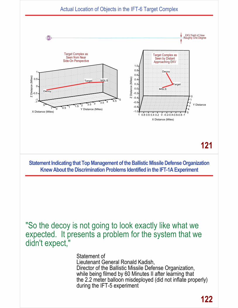
Actual Location of Objects in the IFT-6 Target Complex
-10
1 0 0.5 1 1.5 2 2.5 3 3.5 4 4.5 5-1
-0.5
0
0.5
1
X Distance (Miles)Y Distance (Miles)
Z A
01
23
45
-0.8-0.6-0.4-0.2
-1-0.8-0.6-0.4-0.21 0.20.40.60.8 0
X Distance (Miles)
Y Distance
-1.0
0.0
1.0
0.20.40.6
0.8
MSLS
Target
Decoy
Target MSLS
Decoy
Z D
ista
nce
(Mile
s)
Z D
ista
nce
(Mile
s)
Target Complex as Seen by Distant
Approaching EKV
Target Complex as Seen from Near
Side-On Perspective
EKV Field of View Roughly One Degree
121
Statement Indicating that Top Management of the Ballistic Missile Defense Organization Knew About the Discrimination Problems Identified in the IFT-1A Experiment
"So the decoy is not going to look exactly like what we expected. It presents a problem for the system that we didn't expect,"
Statement of Lieutenant General Ronald Kadish, Director of the Ballistic Missile Defense Organization, while being filmed by 60 Minutes II after learning that the 2.2 meter balloon misdeployed (did not inflate properly) during the IFT-5 experiment
122

IFT-6 Target Complex as Seen By Distant Approaching EKV
Range of Observed Target Complex ~ 230 – 250 km for FOV 1 – 1.5º
~3.5 km
~3 km
2.2 Meter Diameter Balloon (Roughly Ten Times Brighter than the Mock Warhead)
Mock Warhead
Rocket Stage that Deployed the Mock Warhead and Balloon
Balloon Canister is Now the Least Bright Object: Hence, the Balloon Canister Looks Like the Warhead
123
False Targets Cloud Created in Army Ballistic Missile Development Agency
Test Using a Titan II ICBM on January 10, 1975, Signature of Fragmented Tanks (SOFT),
6 Ft Man and Minuteman Warhead
124