Fulltest i Advanced Paper 2 Question Paper Aits 2013 Ft i Jeea Paper 2
Upload
nguyendiepCategory
view
219download
1
NSW PARLIAMENTARY LIBRARY RESEARCH SERVICE
Carbon Capture and Storage
by
Stephanie Baldwin
Briefing Paper No 2/08

RELATED PUBLICATIONS
• Greenhouse Gas Emission Trading, NSW Parliamentary Library Briefing Paper No 2/07.
• The Science of Climate Change, NSW Parliamentary Library
Background Paper No 1/06. ISSN 1325-5142 ISBN 978-0-7313-1833-9 May 2008 © 2008 Except to the extent of the uses permitted under the Copyright Act 1968, no part of this document may be reproduced or transmitted in any form or by any means including information storage and retrieval systems, without the prior written consent from the Librarian, New South Wales Parliamentary Library, other than by Members of the New South Wales Parliament in the course of their official duties.

Carbon Capture and Storage
by
Stephanie Baldwin

NSW PARLIAMENTARY LIBRARY RESEARCH SERVICE David Clune, (MA, PhD, Dip Lib) Manager.............................................. (02) 9230 2484
Gareth Griffith, (BSc (Econ) (Hons), LLB (Hons), PhD), Senior Research Officer, Politics and Government / Law............................ (02) 9230 2356
Jason Arditi, Research Officer (BA, LLB) Research Officer, Law ............ (02) 9230 2768
Tom Edwards (BSc (Hons)), Research Officer, Environment ................... (02) 9230 3085
Stewart Smith (BSc (Hons), MELGL), Research Officer, Environment ... (02) 9230 2798
John Wilkinson (MA, PhD), Research Officer, Economics……………... (02) 9230 2006 Should Members or their staff require further information about this publication please contact the author. Information about Research Publications can be found on the Internet at: www.parliament.nsw.gov.au/WEB_FEED/PHWebContent.nsf/PHPages/LibraryPublications
Advice on legislation or legal policy issues contained in this paper is provided for use in parliamentary debate and for related parliamentary purposes. This paper is not professional legal opinion.

CONTENTS
EXECUTIVE SUMMARY
1.0 INTRODUCTION – CCS IN CONTEXT........................................................ 1 1.1 Why do we need to capture carbon dioxide (CO2)? ......................................... 2 1.2 Definition: What is CCS?................................................................................. 5 1.3 What are ‘clean coal’ technologies?................................................................. 7
2.0 GOVERNMENT INTEREST IN CCS........................................................... 12 2.1 Australian federal policy on CCS................................................................... 12 2.2 Australian state policies on CCS .................................................................... 14 2.3 International government attention on CCS................................................... 21
3.0 CARBON CAPTURE & STORAGE (CCS) TECHNOLOGY ..................... 28 3.1 CO2 capture .................................................................................................... 28 3.2 CO2 transport .................................................................................................. 33 3.3 CO2 storage..................................................................................................... 34 3.4 Integrated (full process chain) CCS projects.................................................. 43
4.0 ISSUES & BARRIERS TO CCS IMPLEMENTATION............................... 46 4.1 Technical barriers ........................................................................................... 46 4.2 Economic cost of CCS.................................................................................... 50 4.3 Legal & international issues ........................................................................... 52 4.4 Environmental & social concerns over CCS.................................................. 53 4.5 Public awareness of CCS................................................................................ 55
5.0 CONCLUSION .............................................................................................. 57 5.1 When is CCS likely to make an impact? ........................................................ 57 5.2 The share of CCS in total emissions mitigation ............................................. 57 5.3 CCS is NOT a ‘magic bullet’ solution ........................................................... 59

Carbon Capture and Storage
EXECUTIVE SUMMARY
Carbon (dioxide) capture and storage (CCS) has been proposed as a potential solution to reduce Australia’s greenhouse gas emissions. Greenhouse gases cause a warming of the Earth’s atmosphere. The most abundant greenhouse gas is carbon dioxide (CO2). The current concentration of CO2 in the atmospheric far exceeds the natural range over the last 650,000 years. The main source of increased CO2concentrations is human-induced fossil fuel emissions. To meet the United Nations Framework Convention on Climate Change (UNFCCC) goal of stabilisation of anthropogenic greenhouse gas emissions, to which Australia is signatory, deep reductions in greenhouse gas emissions are required. There is growing political and industrial support for the technology of carbon capture and storage (CCS) in the belief that it can achieve the deep cuts required in CO2 emissions. CCS is a technology aimed at reducing greenhouse gas emissions from burning fossil fuels during industrial and energy-related processes. It involves the capture, compression, transport, long-term storage and monitoring of CO2, that would otherwise be released to the atmosphere. The advantage of CCS is that widespread use of this technique could achieve significant emissions reductions without the need for rapid change in the energy supply infrastructure. Although both government and industry are placing considerable emphasis on CCS as the key emissions reduction strategy, there are limitations to the extent to which CCS can realistically reduce emissions in Australia, and indeed globally. While each separate part of the CCS process chain has been demonstrated, complete, full-chain CCS has not yet been proven. Fully integrated CCS is currently an immature technology that is unlikely to be operational on a commercial scale for a decade or more. Research suggests that Australia can realistically store a maximum of 25% of our total annual net emissions through geological storage of CO2 (geosequestration). CCS should therefore be considered as a promising but still somewhat unproven option. However, it is likely to come at a significant cost, and is unlikely to make a meaningful contribution for well over a decade. No single technology provides the solution to economically cutting carbon-dioxide emissions from fossil fuel combustion. There are many ways in which CO2 emissions can be reduced, such as improving energy efficiency and switching to renewable and low-carbon methods of electricity generation. However, most scenarios suggest that these steps alone will not achieve the required reductions in CO2 emissions. Carbon capture and storage (CCS) will therefore be only one of a suite of solutions needed to reduce Australia’s greenhouse gas emissions. If the potential of CCS is to be realized, the technique must be safe, environmentally sustainable, cost-effective and capable of being broadly applied. For CCS to achieve its potential as an emissions abatement tool, several hundreds to thousands of CO2 capture systems would need to be installed over the coming century. The actual implementation of CCS is likely to be lower due to factors such as environmental impacts, risks of leakage and the lack of a clear legal framework or public acceptance. In the long-term, the world's energy system may have to be based on non-fossil energy sources. Decarbonising the use of fossil fuels, by capture and storage of CO2, may help the transition to a future carbon-free energy system. This paper examines the current and future capability of CCS to reduce Australia’s greenhouse gas emissions.

Carbon Capture and Storage
1
1.0 INTRODUCTION – CCS IN CONTEXT
Carbon capture and storage (CCS) has been proposed as a potential solution to reduce Australia’s greenhouse gas emissions. Greenhouse gases cause a warming of the Earth’s atmosphere (see Box 1). The most abundant greenhouse gas is carbon dioxide (CO2). The current concentration of CO2 in the atmospheric far exceeds the natural range over the last 650,000 years. CO2 concentration has increased from a pre-industrial value of about 280 parts per million (ppm), to 379ppm in 2005. The primary source of the increased concentration of CO2 results from fossil fuel use. Approximately one third of all CO2 emissions due to human activity come from fossil fuels used for generating electricity, with each power plant capable of emitting several million tonnes of CO2 annually.1 To meet the United Nations Framework Convention on Climate Change (UNFCCC) goal of stabilisation of anthropogenic greenhouse gas emissions, to which Australia is a signatory, deep reductions in greenhouse gas emissions are required. One method that could be used is carbon capture and storage (CCS). CCS provides a means of preventing CO2 from entering the atmosphere and thereby contributing to the enhanced greenhouse effect.2 Carbon capture and storage technology would be used in combination with other mitigation measures (e.g. fuel switching, energy efficiency and renewable energy) to achieve the necessary deep reductions in greenhouse gas emissions.3
There is growing support for the technology of carbon capture and storage (CCS) in the belief that it can achieve the deep cuts required in CO2 emissions. In Australia, a 2007 federal parliament inquiry concluded that ‘If serious cuts in emission are to be achieved by 2050, some form of post-combustion capture technology will need to be part of the CCS strategy’.4 However, CCS is an immature and unproven technology that is unlikely to be operational on a commercial scale in Australia for a decade or more.5 In addition, results from the Australian Petroleum Cooperative Research Centre (APCRC) GEODISC program, which assessed the potential for storage of CO2 in geological formations, show that Australia can realistically store a maximum of 25% of our total annual net emissions through geological storage of CO2 (geosequestration).6 It is likely therefore, that CCS will be only one of a suite of solutions needed to reduce Australia’s greenhouse gas emissions. This paper examines the current and future capability of CCS to reduce Australia’s greenhouse gas emissions.
1 Intergovernmental Panel on Climate Change (IPCC) 4th Assessment Report, 2007, Working Group 1,
Summary for policy makers, http://ipcc-wg1.ucar.edu/wg1/Report/AR4WG1_Print_SPM.pdf 2 Saddler H., Reidy, C. & Passey, R., (2004), Geosequestration. What it is and how much can it contribute to
a sustainable energy policy for Australia? The Australia Institute Discussion Paper No. 72, http://www.tai.org.au/documents/downloads/DP72.pdf
3 International Energy Agency, Greenhouse Gas R&D Programme, http://www.ieagreen.org.uk/ccs.html 4 Between a rock and a hard place. The science of geosequestration. Commonwealth Parliament, House
of Representatives Standing Committee on Science & Innovation, 2007 http://www.aph.gov.au/house/committee/scin/geosequestration/report/front.pdf
5 Passey, R.J. & MacGill, I.F., (2003), The Australian Electricity Industry and Geosequestration – Some Abatement Scenarios. UNSW Centre for Energy & Environmental Markets, (CEEM) Discussion paper http://www.ergo.ee.unsw.edu.au/solar03_geoseqscenarios_passey.pdf
6 Bradshaw, J., Allinson, G., Bradshaw, B.E., Nguyen, V., Rigg, A.J., Spencer, L. & Wilson, P., (2004), Australia’s CO2 geological storage potential and matching of emissions sources to potential sinks. Energy 29, 9-10, p1623-1631
NSW Parliamentary Library Research Service
2
1.1 WHY DO WE NEED TO CAPTURE CARBON DIOXIDE (CO2)?
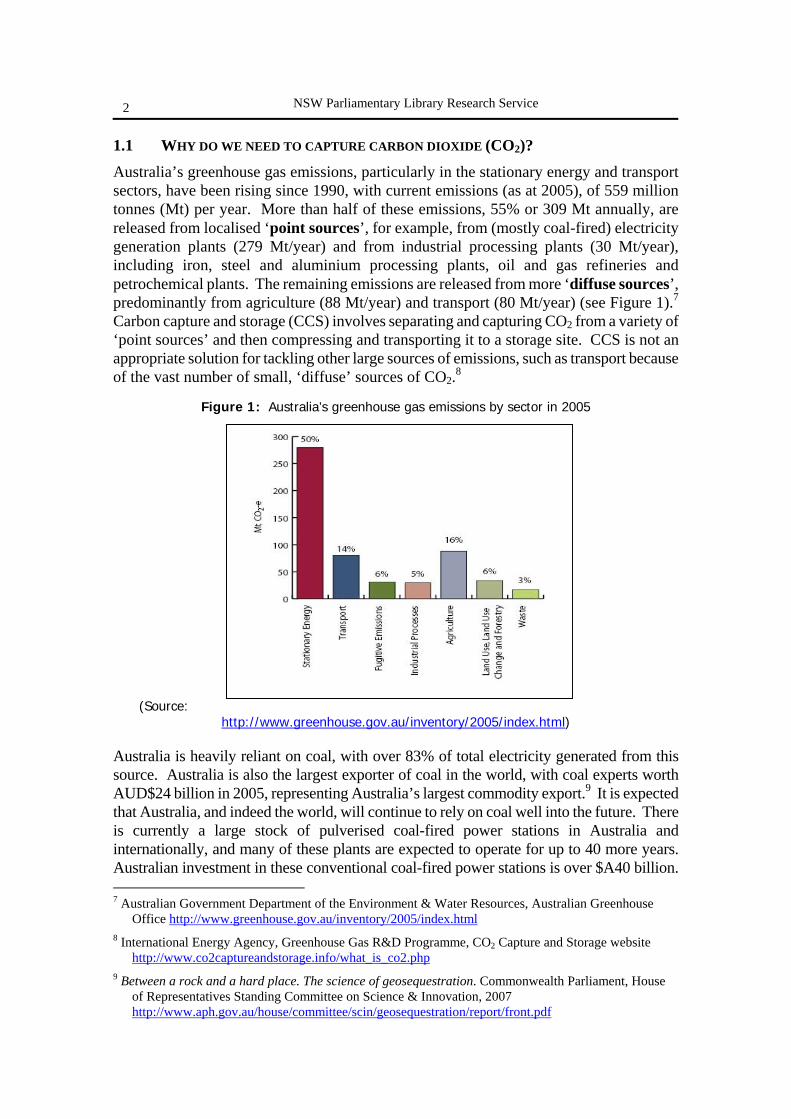
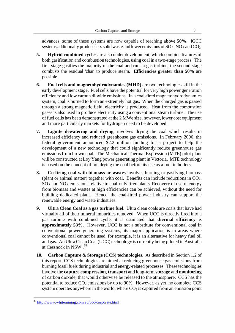
Australia’s greenhouse gas emissions, particularly in the stationary energy and transport sectors, have been rising since 1990, with current emissions (as at 2005), of 559 million tonnes (Mt) per year. More than half of these emissions, 55% or 309 Mt annually, are released from localised ‘point sources’, for example, from (mostly coal-fired) electricity generation plants (279 Mt/year) and from industrial processing plants (30 Mt/year), including iron, steel and aluminium processing plants, oil and gas refineries and petrochemical plants. The remaining emissions are released from more ‘diffuse sources’, predominantly from agriculture (88 Mt/year) and transport (80 Mt/year) (see Figure 1).7 Carbon capture and storage (CCS) involves separating and capturing CO2 from a variety of ‘point sources’ and then compressing and transporting it to a storage site. CCS is not an appropriate solution for tackling other large sources of emissions, such as transport because of the vast number of small, ‘diffuse’ sources of CO2.8
Figure 1: Australia’s greenhouse gas emissions by sector in 2005
(Source: http://www.greenhouse.gov.au/inventory/2005/index.html)
Australia is heavily reliant on coal, with over 83% of total electricity generated from this source. Australia is also the largest exporter of coal in the world, with coal experts worth AUD$24 billion in 2005, representing Australia’s largest commodity export.9 It is expected that Australia, and indeed the world, will continue to rely on coal well into the future. There is currently a large stock of pulverised coal-fired power stations in Australia and internationally, and many of these plants are expected to operate for up to 40 more years. Australian investment in these conventional coal-fired power stations is over $A40 billion. 7 Australian Government Department of the Environment & Water Resources, Australian Greenhouse
Office http://www.greenhouse.gov.au/inventory/2005/index.html 8 International Energy Agency, Greenhouse Gas R&D Programme, CO2 Capture and Storage website
http://www.co2captureandstorage.info/what_is_co2.php 9 Between a rock and a hard place. The science of geosequestration. Commonwealth Parliament, House
of Representatives Standing Committee on Science & Innovation, 2007 http://www.aph.gov.au/house/committee/scin/geosequestration/report/front.pdf
Carbon Capture and Storage
3
These facilities have a forecast operational life of 50 years and by 2020, 38 Gigawatts of this capacity will remain in use.10 As this is the case, Australia is faced with the challenge of reducing greenhouse gas emissions whilst remaining dependent on coal. Reduction in CO2 emissions is essential in order to avoid massive stranded (unusable) assets. Therefore, a technical system such as CCS, that could reduce these emissions to a small fraction of their present level, while allowing continued burning of coal, has great surface appeal.11 A 2007 inquiry by the Australian federal parliament’s science and innovation standing committee similarly concluded that carbon capture and storage (CCS) could offer a possible solution to these competing demands of protecting the environment and protecting the coal industry.12 Although both government and the electricity industry are placing considerable emphasis on carbon capture and storage (CCS) as the key emissions reduction strategy, there are serious limitations to the extent to which CCS can realistically reduce emissions in Australia.13 Energy policy researchers from the University of NSW conclude that CCS should be considered as a promising but still somewhat unproven option that potentially offers very significant abatement potential and good integration into the existing energy industry. However, its abatement is likely to come at a significant (economic) cost, and it is unlikely to be able to make a significant contribution for well over a decade.14
10 www.australiancoal.com.au/cleantech.htm 11 Saddler H., Reidy, C. & Passey, R., (2004), Geosequestration. What it is and how much can it contribute
to a sustainable energy policy for Australia? The Australia Institute Discussion Paper No. 72, http://www.tai.org.au/documents/downloads/DP72.pdf
12 See Footnote 9, Between a rock and a hard place, Federal House of Representatives committee inquiry, 2007
13 Wilkenfeld, G., Hamilton C. and Saddler, H., (2007), Clean coal and other myths, The Australia Institute Research Paper No. 49 www.tai.org.au/documents/downloads/WP108.pdf
14 MacGill, I., Passey, R. & Daly, T., (2006), The limited role for Carbon Capture and Storage (CCS) technologies in a sustainable Australian energy future, Int. J. Env. Studies 63 (6), p751-763

NSW Parliamentary Library Research Service
4
Box 1 - Greenhouse gases and their global warming potentials Greenhouse gases are gases that cause a warming effect (‘greenhouse effect’) by trapping heat from the sun in the Earth’s atmosphere15. There are several gases that are recognised as greenhouse gases. Some of these occur naturally, but increases in their atmospheric concentrations over the last 250 years are due largely to human activities.16 The naturally occurring greenhouse gases are:
• carbon dioxide (CO2), the most abundant greenhouse gas, • methane (CH4), and • nitrous oxide (N2O).
Other greenhouse gases however, are the result of human activities. These are the fluorinated greenhouse gases:
• hydrofluorocarbons (HFCs) used as refrigerants, • perfluorocarbons (PFCs) which are emitted during the manufacture of aluminium and • sulphur hexafluoride (SF6) used in the electronics industry.17
All of these gases cause a warming effect of the atmosphere, and thereby contribute to climate change.
To compare the amount of warming that different greenhouse gases cause, all greenhouse gases are converted to a common measure known as a global warming potential (GWP). GWPs are based on the heat-absorbing ability of each gas relative to that of carbon dioxide (CO2), as well as the decay rate of each gas (the amount removed from the atmosphere over a given number of years) relative to that of CO2.18 The global warming potential (GWP) of each gas is expressed as a carbon dioxide equivalent (CO2eq or CO2e). This internationally accepted common unit allows the warming effect of each gas to be compared.
For example, over a period of 100 years, one tonne of carbon dioxide (CO2) has a global warming potential (GWP) of 1. This compares to methane (CH4), which has a global warming potential of 23, meaning that over 100 years, one tonne of methane causes 23 times more warming than 1 tonne of CO2. CO2 however, is far more abundant in the atmosphere and is emitted in far greater quantities than CH4.
Greenhouse Gas Global Warming Potential (over 100 years)19
CO2 (carbon dioxide) 1 CH4 (methane) 23 N2O (nitrous oxide) 296 HFCs (hydrofluorocarbons) 120-12,000 PFCs (perfluorocarbons) 5,700-11,900 SF6 (sulphur hexafluoride) 22,200
15 http://www.climatecare.org.business/jargon-buster/ 16 IPCC 4th Assessment Report 2007, Technical Summary, p23
http://ipcc-wg1.ucar.edu/wg1/Report/A4WG1_Print_TS.pdf 17 http://ec.europa.eu/environment/climat/campaign/pdf/gases_en.pdf 18 See footnote 15 19 IPCC 3rd Assessment Report 2001, Technical Summary, p47, http://www.ipcc.ch/pub/wg1TARtechsum.pdf
Carbon Capture and Storage
5
1.2 DEFINITION: WHAT IS CCS?
Carbon dioxide capture and storage (CCS) is a technology aimed at reducing greenhouse gas emissions from burning fossil fuels during industrial and energy-related processes.
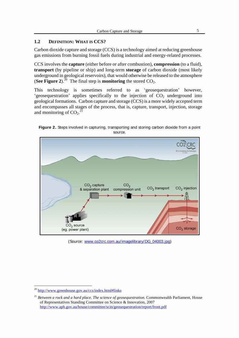
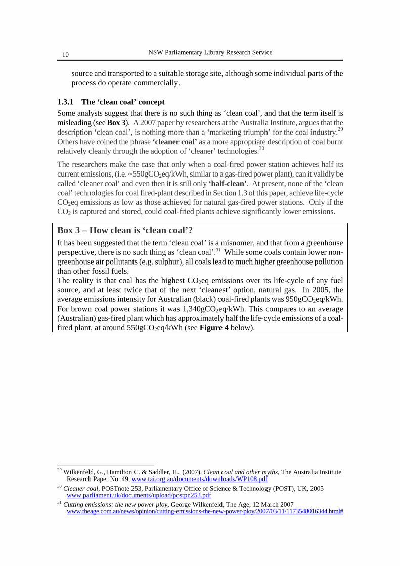
CCS involves the capture (either before or after combustion), compression (to a fluid), transport (by pipeline or ship) and long-term storage of carbon dioxide (most likely underground in geological reservoirs), that would otherwise be released to the atmosphere (See Figure 2).20 The final step is monitoring the stored CO2.
This technology is sometimes referred to as ‘geosequestration’ however, ‘geosequestration’ applies specifically to the injection of CO2 underground into geological formations. Carbon capture and storage (CCS) is a more widely accepted term and encompasses all stages of the process, that is, capture, transport, injection, storage and monitoring of CO2.21
Figure 2. Steps involved in capturing, transporting and storing carbon dioxide from a point
source.
(Source: www.co2crc.com.au/imagelibrary/DG_04003.jpg)
20 http://www.greenhouse.gov.au/ccs/index.html#links 21 Between a rock and a hard place. The science of geosequestration. Commonwealth Parliament, House
of Representatives Standing Committee on Science & Innovation, 2007 http://www.aph.gov.au/house/committee/scin/geosequestration/report/front.pdf

NSW Parliamentary Library Research Service
6
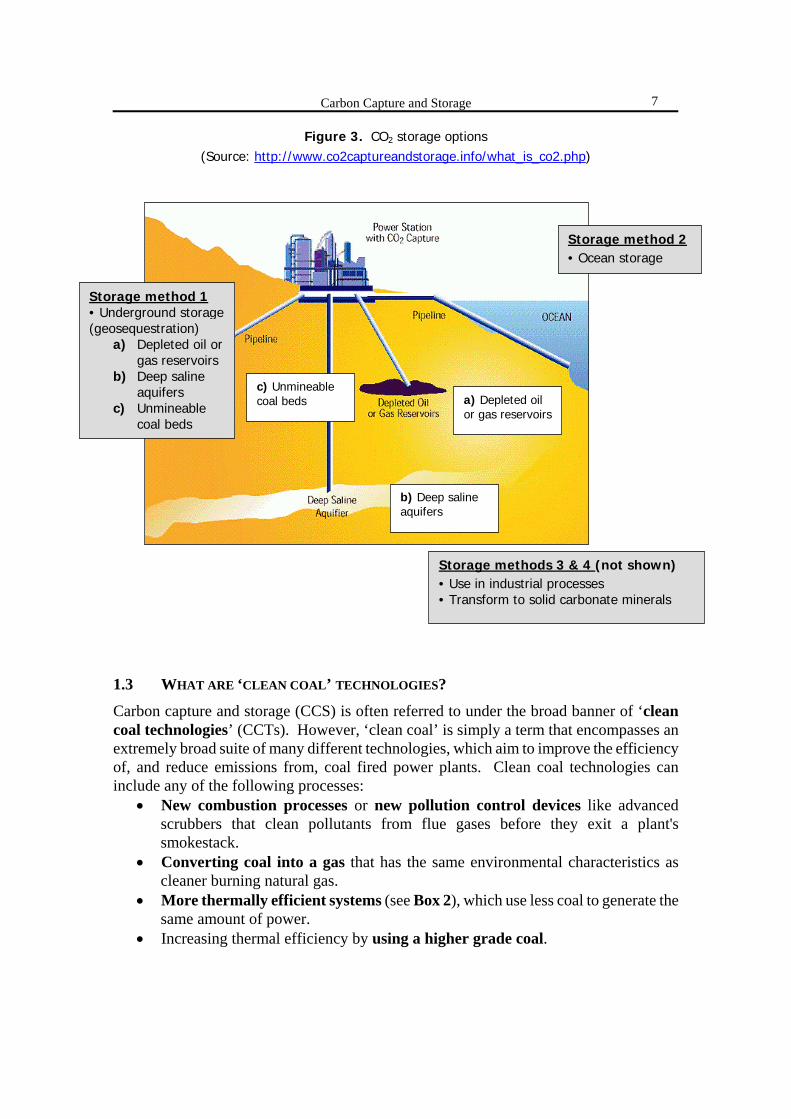
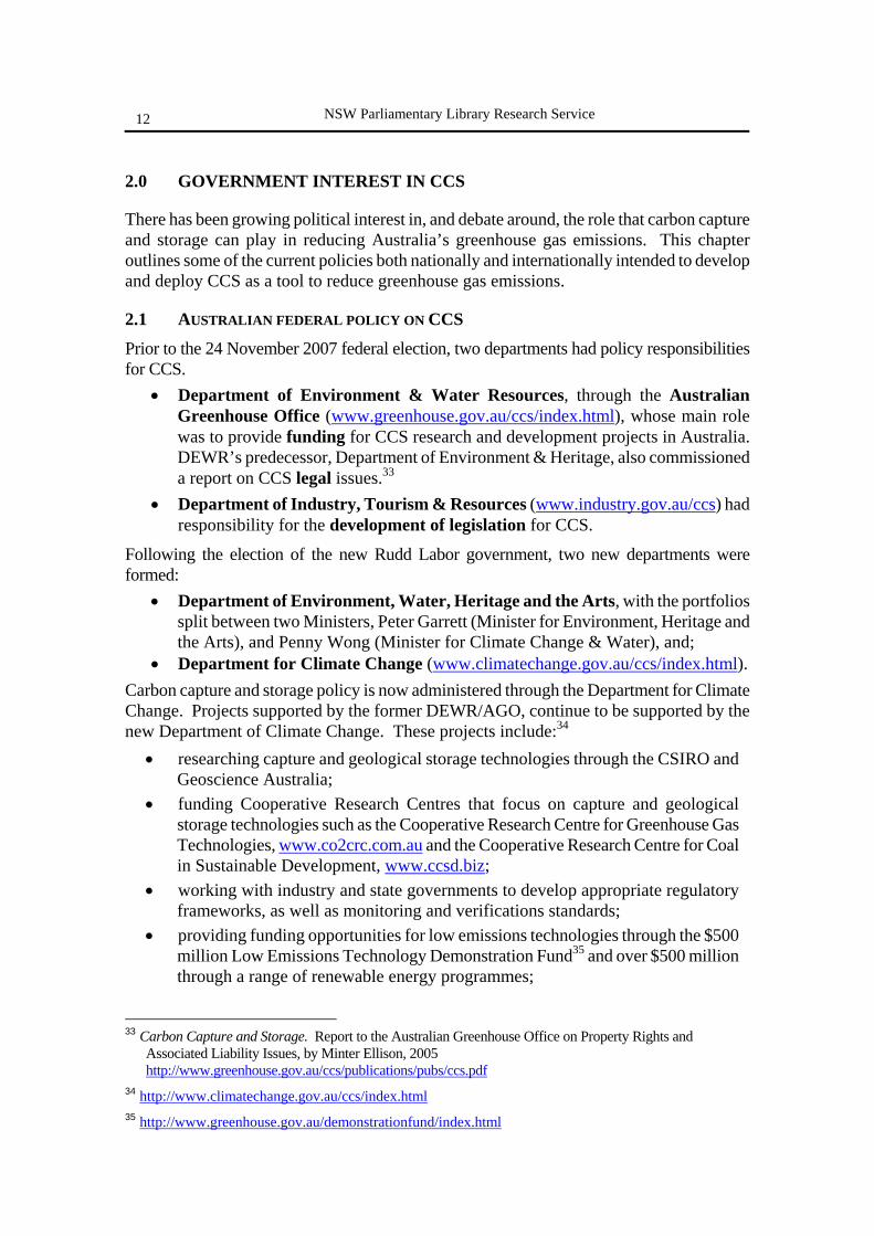
There are several methods proposed for storing CO2 (See Figure 3, next page).22 Each of these methods listed here is discussed in more detail in Chapter 3.3.
1. Underground storage - in geological reservoirs such as depleted oil/gas fields, unmineable coal beds or deep saline formations.23 This method of storage is also referred to as ‘geosequestration’. Pros: Most advanced CO2 storage technology. Individual parts of the CCS process chain already operate at demonstration or commercial scales. Cons: The entire, integrated CCS process chain has not yet been proved. This technology is also expensive compared to the current price of carbon.
2. Ocean storage - Direct release into the oceans; either into the water column or onto the seafloor. Pros: Oceans have a large capacity to absorb and store CO2. Cons: The ocean is an open system and it would be difficult to contain and monitor stored CO2. The impact of raised levels of CO2 on marine ecosystems is also poorly understood.
3. Use in industrial processes - e.g. in fertilizer production, refrigeration, food & beverages, etc. Pros: These processes and industries already exist on a commercial scale. Cons: Only a very small amount of CO2 is used for these purposes, and it is only stored for days to months, so would not contribute meaningfully to climate change mitigation.
4. Solid storage - Transform CO2 gas into solid carbonate minerals. Pros: Results in inert, natural mineral compounds which are stable over long periods of time, and do not release CO2 back into the atmosphere. Cons: This technology is costly and energy inefficient, and still only at the research phase.
22 Intergovernmental Panel on Climate Change (IPCC) Special Report, Carbon Dioxide Capture and Storage,
(2005), Summary for Policymakers and Technical Summary, p2, (www.ipcc.ch) 23 Saline formations are sedimentary rocks saturated with salty water. The water they contain is
unsuitable for agriculture or human consumption (Footnote 22, IPCC Special Report on CCS, Summary, p2)
Carbon Capture and Storage
7
Figure 3. CO2 storage options (Source: http://www.co2captureandstorage.info/what_is_co2.php)
1.3 WHAT ARE ‘CLEAN COAL’ TECHNOLOGIES?
Carbon capture and storage (CCS) is often referred to under the broad banner of ‘clean coal technologies’ (CCTs). However, ‘clean coal’ is simply a term that encompasses an extremely broad suite of many different technologies, which aim to improve the efficiency of, and reduce emissions from, coal fired power plants. Clean coal technologies can include any of the following processes:
• New combustion processes or new pollution control devices like advanced scrubbers that clean pollutants from flue gases before they exit a plant's smokestack.
• Converting coal into a gas that has the same environmental characteristics as cleaner burning natural gas.
• More thermally efficient systems (see Box 2), which use less coal to generate the same amount of power.
• Increasing thermal efficiency by using a higher grade coal.
Storage method 2• Ocean storage
Storage method 1 • Underground storage (geosequestration)
a) Depleted oil or gas reservoirs
b) Deep saline aquifers
c) Unmineable coal beds
Storage methods 3 & 4 (not shown) • Use in industrial processes • Transform to solid carbonate minerals
c) Unmineable coal beds
b) Deep saline aquifers
a) Depleted oil or gas reservoirs
NSW Parliamentary Library Research Service
8
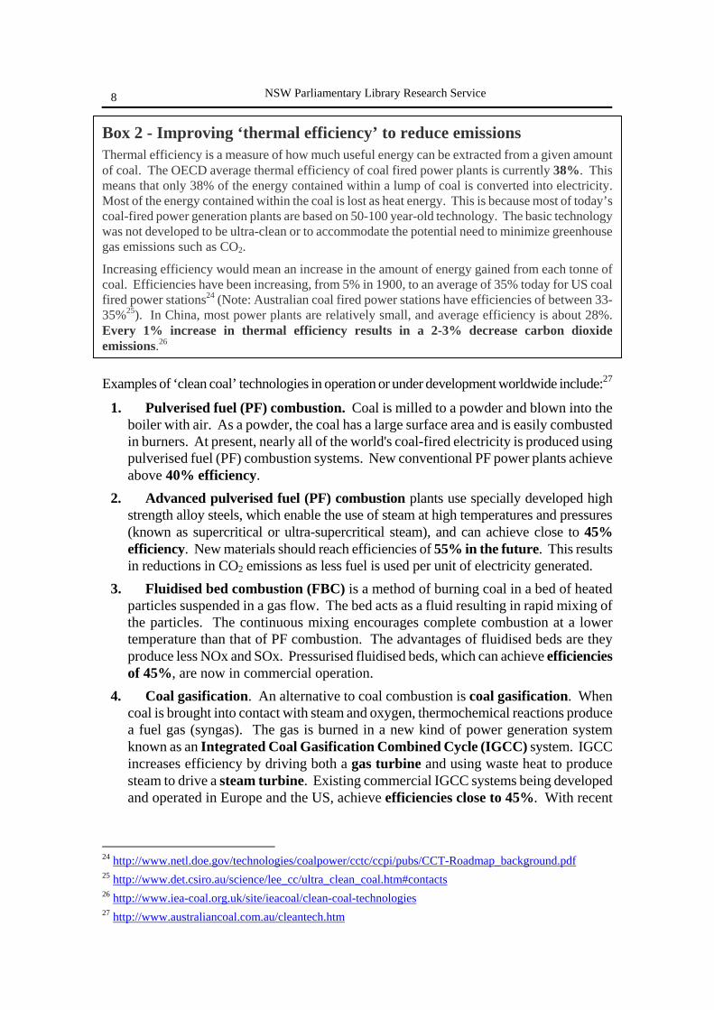
Box 2 - Improving ‘thermal efficiency’ to reduce emissions Thermal efficiency is a measure of how much useful energy can be extracted from a given amount of coal. The OECD average thermal efficiency of coal fired power plants is currently 38%. This means that only 38% of the energy contained within a lump of coal is converted into electricity. Most of the energy contained within the coal is lost as heat energy. This is because most of today’s coal-fired power generation plants are based on 50-100 year-old technology. The basic technology was not developed to be ultra-clean or to accommodate the potential need to minimize greenhouse gas emissions such as CO2.
Increasing efficiency would mean an increase in the amount of energy gained from each tonne of coal. Efficiencies have been increasing, from 5% in 1900, to an average of 35% today for US coal fired power stations24 (Note: Australian coal fired power stations have efficiencies of between 33-35%25). In China, most power plants are relatively small, and average efficiency is about 28%. Every 1% increase in thermal efficiency results in a 2-3% decrease carbon dioxide emissions.26 Examples of ‘clean coal’ technologies in operation or under development worldwide include:27
1. Pulverised fuel (PF) combustion. Coal is milled to a powder and blown into the boiler with air. As a powder, the coal has a large surface area and is easily combusted in burners. At present, nearly all of the world's coal-fired electricity is produced using pulverised fuel (PF) combustion systems. New conventional PF power plants achieve above 40% efficiency.
2. Advanced pulverised fuel (PF) combustion plants use specially developed high strength alloy steels, which enable the use of steam at high temperatures and pressures (known as supercritical or ultra-supercritical steam), and can achieve close to 45% efficiency. New materials should reach efficiencies of 55% in the future. This results in reductions in CO2 emissions as less fuel is used per unit of electricity generated.
3. Fluidised bed combustion (FBC) is a method of burning coal in a bed of heated particles suspended in a gas flow. The bed acts as a fluid resulting in rapid mixing of the particles. The continuous mixing encourages complete combustion at a lower temperature than that of PF combustion. The advantages of fluidised beds are they produce less NOx and SOx. Pressurised fluidised beds, which can achieve efficiencies of 45%, are now in commercial operation.
4. Coal gasification. An alternative to coal combustion is coal gasification. When coal is brought into contact with steam and oxygen, thermochemical reactions produce a fuel gas (syngas). The gas is burned in a new kind of power generation system known as an Integrated Coal Gasification Combined Cycle (IGCC) system. IGCC increases efficiency by driving both a gas turbine and using waste heat to produce steam to drive a steam turbine. Existing commercial IGCC systems being developed and operated in Europe and the US, achieve efficiencies close to 45%. With recent
24 http://www.netl.doe.gov/technologies/coalpower/cctc/ccpi/pubs/CCT-Roadmap_background.pdf 25 http://www.det.csiro.au/science/lee_cc/ultra_clean_coal.htm#contacts 26 http://www.iea-coal.org.uk/site/ieacoal/clean-coal-technologies 27 http://www.australiancoal.com.au/cleantech.htm
Carbon Capture and Storage
9
advances, some of these systems are now capable of reaching above 50%. IGCC systems additionally produce less solid waste and lower emissions of SOx, NOx and CO2.
5. Hybrid combined cycles are also under development, which combine features of both gasification and combustion technologies, using coal in a two-stage process. The first stage gasifies the majority of the coal and runs a gas turbine, the second stage combusts the residual 'char' to produce steam. Efficiencies greater than 50% are possible.
6. Fuel cells and magnetohydrodynamics (MHD) are two technologies still in the early development stage. Fuel cells have the potential for very high power generation efficiency and low carbon dioxide emissions. In a coal-fired magnetohydrodynamics system, coal is burned to form an extremely hot gas. When the charged gas is passed through a strong magnetic field, electricity is produced. Heat from the combustion gases is also used to produce electricity using a conventional steam turbine. The use of fuel cells has been demonstrated at the 2 MWe size, however, lower cost equipment and more particularly markets for hydrogen need to be developed.
7. Lignite dewatering and drying, involves drying the coal which results in increased efficiency and reduced greenhouse gas emissions. In February 2006, the federal government announced $2.2 million funding for a project to help the development of a new technology that could significantly reduce greenhouse gas emissions from brown coal. The Mechanical Thermal Expression (MTE) pilot plant will be constructed at Loy Yang power generating plant in Victoria. MTE technology is based on the concept of pre drying the coal before its use as a fuel in boilers.
8. Co-firing coal with biomass or wastes involves burning or gasifying biomass (plant or animal matter) together with coal. Benefits can include reductions in CO2, SOx and NOx emissions relative to coal-only fired plants. Recovery of useful energy from biomass and wastes at high efficiencies can be achieved, without the need for building dedicated plant. Hence, the coal-fired power industry can support the renewable energy and waste industries.
9. Ultra Clean Coal as a gas turbine fuel. Ultra clean coals are coals that have had virtually all of their mineral impurities removed. When UCC is directly fired into a gas turbine with combined cycle, it is estimated that thermal efficiency is approximately 53%. However, UCC is not a substitute for conventional coal in conventional power generating systems; its major application is in areas where conventional coal cannot be used, for example, it is an alternative for heavy fuel oil and gas. An Ultra Clean Coal (UCC) technology is currently being piloted in Australia at Cessnock in NSW..28
10. Carbon Capture & Storage (CCS) technologies. As described in Section 1.2 of this report, CCS technologies are aimed at reducing greenhouse gas emissions from burning fossil fuels during industrial and energy-related processes. These technologies involve the capture compression, transport and long-term storage and monitoring of carbon dioxide, that would otherwise be released to the atmosphere. CCS has the potential to reduce CO2 emissions by up to 90%. However, as yet, no complete CCS system operates anywhere in the world, where CO2 is captured from an emission point
28 http://www.whitemining.com.au/ucc-corporate.html
NSW Parliamentary Library Research Service
10
source and transported to a suitable storage site, although some individual parts of the process do operate commercially.
1.3.1 The ‘clean coal’ concept Some analysts suggest that there is no such thing as ‘clean coal’, and that the term itself is misleading (see Box 3). A 2007 paper by researchers at the Australia Institute, argues that the description ‘clean coal’, is nothing more than a ‘marketing triumph’ for the coal industry.29 Others have coined the phrase ‘cleaner coal’ as a more appropriate description of coal burnt relatively cleanly through the adoption of ‘cleaner’ technologies.30
The researchers make the case that only when a coal-fired power station achieves half its current emissions, (i.e. ~550gCO2eq/kWh, similar to a gas-fired power plant), can it validly be called ‘cleaner coal’ and even then it is still only ‘half-clean’. At present, none of the ‘clean coal’ technologies for coal fired-plant described in Section 1.3 of this paper, achieve life-cycle CO2eq emissions as low as those achieved for natural gas-fired power stations. Only if the CO2 is captured and stored, could coal-fried plants achieve significantly lower emissions.
Box 3 – How clean is ‘clean coal’? It has been suggested that the term ‘clean coal’ is a misnomer, and that from a greenhouse perspective, there is no such thing as ‘clean coal’.31 While some coals contain lower non-greenhouse air pollutants (e.g. sulphur), all coals lead to much higher greenhouse pollution than other fossil fuels. The reality is that coal has the highest CO2eq emissions over its life-cycle of any fuel source, and at least twice that of the next ‘cleanest’ option, natural gas. In 2005, the average emissions intensity for Australian (black) coal-fired plants was 950gCO2eq/kWh. For brown coal power stations it was 1,340gCO2eq/kWh. This compares to an average (Australian) gas-fired plant which has approximately half the life-cycle emissions of a coal-fired plant, at around 550gCO2eq/kWh (see Figure 4 below).
29 Wilkenfeld, G., Hamilton C. & Saddler, H., (2007), Clean coal and other myths, The Australia Institute
Research Paper No. 49, www.tai.org.au/documents/downloads/WP108.pdf 30 Cleaner coal, POSTnote 253, Parliamentary Office of Science & Technology (POST), UK, 2005
www.parliament.uk/documents/upload/postpn253.pdf 31 Cutting emissions: the new power ploy, George Wilkenfeld, The Age, 12 March 2007
www.theage.com.au/news/opinion/cutting-emissions-the-new-power-ploy/2007/03/11/1173548016344.html#

Carbon Capture and Storage
11
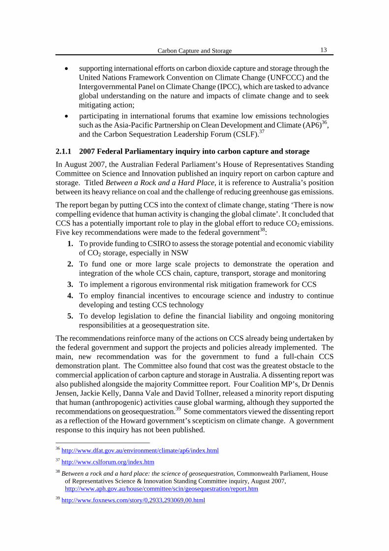
Figure 4. Life-cycle CO2eq emissions for different electricity generation technologies worldwide.32
32 Carbon footprint of electricity generation, POSTnote 268, Parliamentary Office of Science & Technology
(POST), UK, 2006, www.parliament.uk/documents/upload/postpn268.pdf
0
200
400
600
800
1000
1200
Coal Gas Biomass PV Marine Hydro Wind Nuclear
gCO2eq/kWh
Highest carbon footprint globally
Lowest carbon footprint globally
The range in footprint for each technology reflects differences in: • operating efficiencies (for gas, coal & PV) • raw materials combusted (for biomass) • manufacturing efficiencies (for wind & marine) • stored vs. run-of-river dam types (for hydro) and, • electricity used to refine raw materials (for nuclear)
NSW Parliamentary Library Research Service
12
2.0 GOVERNMENT INTEREST IN CCS
There has been growing political interest in, and debate around, the role that carbon capture and storage can play in reducing Australia’s greenhouse gas emissions. This chapter outlines some of the current policies both nationally and internationally intended to develop and deploy CCS as a tool to reduce greenhouse gas emissions.
2.1 AUSTRALIAN FEDERAL POLICY ON CCS
Prior to the 24 November 2007 federal election, two departments had policy responsibilities for CCS.
• Department of Environment & Water Resources, through the Australian Greenhouse Office (www.greenhouse.gov.au/ccs/index.html), whose main role was to provide funding for CCS research and development projects in Australia. DEWR’s predecessor, Department of Environment & Heritage, also commissioned a report on CCS legal issues.33
• Department of Industry, Tourism & Resources (www.industry.gov.au/ccs) had responsibility for the development of legislation for CCS.
Following the election of the new Rudd Labor government, two new departments were formed:
• Department of Environment, Water, Heritage and the Arts, with the portfolios split between two Ministers, Peter Garrett (Minister for Environment, Heritage and the Arts), and Penny Wong (Minister for Climate Change & Water), and;
• Department for Climate Change (www.climatechange.gov.au/ccs/index.html). Carbon capture and storage policy is now administered through the Department for Climate Change. Projects supported by the former DEWR/AGO, continue to be supported by the new Department of Climate Change. These projects include:34
• researching capture and geological storage technologies through the CSIRO and Geoscience Australia;
• funding Cooperative Research Centres that focus on capture and geological storage technologies such as the Cooperative Research Centre for Greenhouse Gas Technologies, www.co2crc.com.au and the Cooperative Research Centre for Coal in Sustainable Development, www.ccsd.biz;
• working with industry and state governments to develop appropriate regulatory frameworks, as well as monitoring and verifications standards;
• providing funding opportunities for low emissions technologies through the $500 million Low Emissions Technology Demonstration Fund35 and over $500 million through a range of renewable energy programmes;
33 Carbon Capture and Storage. Report to the Australian Greenhouse Office on Property Rights and
Associated Liability Issues, by Minter Ellison, 2005 http://www.greenhouse.gov.au/ccs/publications/pubs/ccs.pdf
34 http://www.climatechange.gov.au/ccs/index.html 35 http://www.greenhouse.gov.au/demonstrationfund/index.html
Carbon Capture and Storage
13
• supporting international efforts on carbon dioxide capture and storage through the United Nations Framework Convention on Climate Change (UNFCCC) and the Intergovernmental Panel on Climate Change (IPCC), which are tasked to advance global understanding on the nature and impacts of climate change and to seek mitigating action;
• participating in international forums that examine low emissions technologies such as the Asia-Pacific Partnership on Clean Development and Climate (AP6)36, and the Carbon Sequestration Leadership Forum (CSLF).37
2.1.1 2007 Federal Parliamentary inquiry into carbon capture and storage
In August 2007, the Australian Federal Parliament’s House of Representatives Standing Committee on Science and Innovation published an inquiry report on carbon capture and storage. Titled Between a Rock and a Hard Place, it is reference to Australia’s position between its heavy reliance on coal and the challenge of reducing greenhouse gas emissions.
The report began by putting CCS into the context of climate change, stating ‘There is now compelling evidence that human activity is changing the global climate’. It concluded that CCS has a potentially important role to play in the global effort to reduce CO2 emissions. Five key recommendations were made to the federal government38:
1. To provide funding to CSIRO to assess the storage potential and economic viability of CO2 storage, especially in NSW
2. To fund one or more large scale projects to demonstrate the operation and integration of the whole CCS chain, capture, transport, storage and monitoring
3. To implement a rigorous environmental risk mitigation framework for CCS 4. To employ financial incentives to encourage science and industry to continue
developing and testing CCS technology 5. To develop legislation to define the financial liability and ongoing monitoring
responsibilities at a geosequestration site.
The recommendations reinforce many of the actions on CCS already being undertaken by the federal government and support the projects and policies already implemented. The main, new recommendation was for the government to fund a full-chain CCS demonstration plant. The Committee also found that cost was the greatest obstacle to the commercial application of carbon capture and storage in Australia. A dissenting report was also published alongside the majority Committee report. Four Coalition MP’s, Dr Dennis Jensen, Jackie Kelly, Danna Vale and David Tollner, released a minority report disputing that human (anthropogenic) activities cause global warming, although they supported the recommendations on geosequestration.39 Some commentators viewed the dissenting report as a reflection of the Howard government’s scepticism on climate change. A government response to this inquiry has not been published. 36 http://www.dfat.gov.au/environment/climate/ap6/index.html 37 http://www.cslforum.org/index.htm 38 Between a rock and a hard place: the science of geosequestration, Commonwealth Parliament, House
of Representatives Science & Innovation Standing Committee inquiry, August 2007, http://www.aph.gov.au/house/committee/scin/geosequestration/report.htm
39 http://www.foxnews.com/story/0,2933,293069,00.html
NSW Parliamentary Library Research Service
14
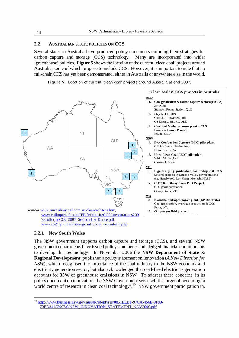
2.2 AUSTRALIAN STATE POLICIES ON CCS Several states in Australia have produced policy documents outlining their strategies for carbon capture and storage (CCS) technology. Many are incorporated into wider ‘greenhouse’ policies. Figure 5 shows the location of the current ‘clean coal’ projects around Australia, some of which propose to include CCS. However, it is important to note that no full-chain CCS has yet been demonstrated, either in Australia or anywhere else in the world.
Figure 5. Location of current ‘clean coal’ projects around Australia at end 2007.
2.2.1 New South Wales
The NSW government supports carbon capture and storage (CCS), and several NSW government departments have issued policy statements and pledged financial commitments to develop this technology. In November 2006 the NSW Department of State & Regional Development, published a policy statement on innovation (A New Direction for NSW), which recognised the importance of the coal industry to the NSW economy and electricity generation sector, but also acknowledged that coal-fired electricity generation accounts for 35% of greenhouse emissions in NSW. To address these concerns, in its policy document on innovation, the NSW Government sets itself the target of becoming ‘a world centre of research in clean coal technology’.40 NSW government participation in,
40 http://www.business.nsw.gov.au/NR/rdonlyres/0851EEBF-97CA-456E-9F99-
73ED34153997/0/NSW_INNOVATION_STATEMENT_NOV2006.pdf
1
9
7
5
23
6
48
‘Clean coal’ & CCS projects in Australia QLD 1. Coal gasification & carbon capture & storage (CCS) ZeroGen Stanwell Power Station, QLD 2. Oxy fuel + CCS Callide A Power Station CS Energy, Biloela, QLD 3. Coal Bed Methane power plant + CCS Fairview Power Project Injune, QLD NSW 4. Post Combustion Capture (PCC) pilot plant CSIRO Energy Technology Newcastle, NSW 5. Ultra Clean Coal (UCC) pilot plant White Mining Ltd. Cessnock, NSW VIC 6. Lignite drying, gasification, coal-to-liquid & CCS Several projects in Latrobe Valley power stations e.g. Hazelwood, Loy Yang, Monash, HRLT 7. CO2CRC Otway Basin Pilot Project CO2 geosequestration Otway Basin, VIC WA
8. Kwinana hydrogen power plant, (BP/Rio Tinto) Coal gasification, hydrogen production & CCS Perth, WA 9. Gorgon gas field project
C b C t & St (CCS)Sources:www.australiancoal.com.au/cleantechAus.htm,
www.colloqueco2.com/IFP/fr/minisiteCO2/presentations2007/ColloqueCO2-2007_Session1_6-Dance.pdf, www.co2captureandstorage.info/cont_australasia.php
WA
SA
QLD
NT
VIC
NSW
TAS
Carbon Capture and Storage
15
and financial support for CCS projects currently includes: • The establishment of the NSW Clean Coal Technologies Working Group, to
identify priorities and targets to reduce carbon emissions from coal • A pledge of $22 million, by the NSW Department for Primary Industries, for
two pilot clean coal projects to reduce greenhouse emissions from power stations in NSW.41 o The first is a geosequestration project, a joint venture among coal
companies, research institutions, generation companies and the Department of Primary Industries, to identify potential sites in NSW that could be used for storage of carbon dioxide. A $5 million Post Combustion Capture pilot facility, operational by mid 2008, will capture greenhouse gas emissions from the Munmorah Power Station on the State’s central coast. It is hoped this project will provide the foundation for a large scale $150 million post combustion capture and storage demonstration project in NSW, operational by 2013.42
o An Ultra Clean Coal project will produce high purity, cleaned coal that can be burnt directly in gas turbines. Ultra clean coal fired turbines can potentially reduce greenhouse gas emissions by 20 to 30%. To assist this project, the NSW Government will grant freehold land valued at $1.9 million and a long term lease to UCC Energy for the construction of a demonstration plant at Cessnock.43
• The Newcastle Ports Corporation is also sponsoring a PhD research fellowship into clean coal in conjunction with Newcastle University.
• The 2007-08 NSW government budget paper, published by the NSW Department of Premier and Cabinet, also mentioned the government’s financial support for research into CCS technologies.44
The NSW government is also a partner in several national CCS related projects including the Coal21 National Action plan and the Cooperative Research Centre for Greenhouse Gas Technologies (CO2CRC), both of which support clean coal technologies.
In May 2007, the NSW Minister for Primary Industries, Energy, Mineral Resources and State Development, the Hon Ian MacDonald MLC, outlined the Government’s commitment to clean coal technologies:45
We have a long-term target of 60% reduction in greenhouse gas emissions by 2050. Clean coal technologies in New South Wales will be a key factor in achieving this target, and will help both Australia and New South Wales adapt to a carbon-constrained future. Clean coal research was identified as one of five key actions in the Government's statement on innovation…We cannot have a climate change policy that does not take into account short-term reliance on fossil fuels…In New South Wales about 90% of our electricity needs are met from coal-fired power stations. Burning coal without adding to global carbon
41 http://www.dpi.nsw.gov.au/archive/news-releases/minerals-and-petroleum/2007/cleaning-up-coal 42 http://www.dpi.nsw.gov.au/aboutus/news/recent-news/minerals-and-petroleum/first-clean-coal-project 43 http://www.uccenergy.com.au/ 44 http://www.premiers.nsw.gov.au/NR/rdonlyres/7D6DD87C-611A-48D9-800E-6D5167C03517/0/app3.pdf 45 http://www.parliament.nsw.gov.au/prod/PARLMENT/hansArt.nsf/V3Key/LC20070529030
NSW Parliamentary Library Research Service
16
dioxide levels is a major technological challenge that must be addressed. A number of technologies can be considered, including the strategy of advancing CO2 capture and storage, advanced pollution control devices…, coal gasification and advanced coal-fired power stations…
In 2008, following further statements of support for clean coal technologies by the Premier, Hon Morris Iemma MP, a Clean Coal Bill was introduced in the NSW Parliament on 11 April 2008.46 The bill establishes a fund for research into, and development of, clean coal technologies, including demonstration projects, and can also be used to increase public awareness of clean coal technologies, and for the commercialisation of these technologies.
2.2.2 Victoria
Victoria has huge reserves of coal and this, along with gas, will remain the major source of electricity for many years. However, 55% of Victoria’s greenhouse gas emissions come from the burning of coal to generate electricity. The Victorian government supports research into finding technologies to reduce greenhouse emissions from power stations and natural gas wells, and that one such technology may be carbon capture and storage (CCS). Some of the most suitable sites in Australia for the geological storage of carbon dioxide are in, or adjacent to, Victoria and are located close to the major Latrobe Valley Power stations. In September 2004 the Victorian Department of Primary Industries (DPI) produced an information paper, Geosequestration: Putting the Carbon Back, to provide an overview of how CCS could work and the challenges that need to be addressed.47
The Victorian government supports the development of greenhouse abatement technologies through a number of collaborations and initiatives.
• The Victorian Government has provided $14 million to establish the Centre for Energy and Greenhouse Technologies (CEGT). The Centre works in partnership with industry and research bodies to co-ordinate research in the areas of energy and greenhouse.
• Victoria is a major supporter of the international Carbon Sequestration Leadership Forum (CSLF) and jointly hosted, along with the Commonwealth Government, the 2nd meeting in Melbourne in September 2004.
• Victoria is a member of the CO2CRC, (Cooperative Research Centre for Greenhouse Gas Technologies). The CO2CRC is running a pilot project in the Otway Basin, which involves producing reserves of CO2 from underground to simulate the capture of CO2 from power stations, followed by separating, compressing and re-injecting the CO2 into different reservoirs to determine the safety and feasibility of geosequestration.48
• Melbourne and Monash universities conduct significant research into geosequestration technologies, particularly related to the capture and separation of CO2.
46http://www.parliament.nsw.gov.au/prod/parlment/nswbills.nsf/1d4800a7a88cc2abca256e9800121f01/e644a
f95bdaff63bca2574270023a9b1!OpenDocument 47http://www.dpi.vic.gov.au/dpi/nrenmp.nsf/childdocs/-4f28e33151f2f0394a256a8000189721-
9942dd73f54af5edca256f84007a15db?open 48 http://www.co2crc.com.au/pilot/OBPP.html
Carbon Capture and Storage
17
• The CRC for Clean Power from Lignite is based in Victoria and is conducting research into coal drying to address the inefficiencies caused by the very high moisture content of Victorian coal. These processes could lead to significant reductions in greenhouse emissions from existing power stations as well as provide a technology that will benefit new power stations, including in countries such as China.
• Monash and Swinburne universities work with the CRC for Clean Power from Lignite in the development of coal drying technologies. They also work with the CRC in areas associated with gasification and other combustion efficiency technologies.
In addition to government funding for greenhouse gas abatement technologies, several private companies in Victoria are also investing in these technologies.
• APEL is a private company that has been awarded an exploration licence to some of the vast Latrobe Valley brown coal reserves. APEL proposes to construct a coal-to-liquids (low sulphur diesel) plant that will produce near zero emissions through geosequestration.
• International Power Limited, operators of the Hazelwood Power Station, have formed an alliance with other companies to develop a high-efficiency plant that could produce liquid fuels or electricity. They believe that they can reduce CO2 emissions by a significant amount and that the flue gas would be readily geosequesterable.49
• HRL is a private firm of consultants specializing in issues relating to coal and was formed from the research arm of the now privatised State Electricity Commission of Victoria. HRL is working towards an 800MW high-efficiency (low greenhouse emissions) power station by integrating coal drying and gasification to produce electricity.
In February 2006, the federal government announced funding of $2.2 million for a project to help the development of a new technology that could significantly reduce greenhouse gas emissions from brown coal. The Mechanical Thermal Expression (MTE) pilot plant will be constructed at Loy Yang power station in Victoria.50
2.2.3 Queensland
Queensland has abundant supplies of low-cost, high-quality black thermal coal. Its coal industry is worth AUD$18 billion a year, and employs 18,000 people. While recognising the economic importance of coal to the state, the Queensland government acknowledges that power station emissions are significant, accounting for approximately 40% of total greenhouse gas emissions in Queensland. Under the Queensland Government’s ClimateSmart 2050 strategy, any new base load electricity generation application will be required to balance both economic and environmental outcomes.
The Queensland Government has committed a total of $900 million to research and develop ‘clean coal’ technologies. $300 million comes from the Queensland Future Growth Fund, with a further $600 million to be contributed from Queensland’s coal industry over 10 years. A joint industry-government Clean Coal Council has been established to oversee
49 http://www.ipplc.com.au/Page.php?iPageID=38&op=Display&iNewsID=421 50 http://www.australiancoal.com.au/cleantechAus.htm
NSW Parliamentary Library Research Service
18
the development of several demonstration projects and to allocate funding. Other ‘clean coal’ research and development projects supported by the Queensland government include;51
• the $26 million Centre for Low Emission Technology (cLET); • the Cooperative Research Centre for Coal in Sustainable Development (CCSD), as
a collaborative investment with industry. • The world-first ZeroGen Project, which will test the feasibility of a demonstration
project of integrated gasification combined cycle (IGCC) generation with carbon capture and storage (CCS). Stanwell, a Queensland government owned corporation, is the contractor responsible for the management of the project, in conjunction with external partners including, the US EPRI (Electric Power Research Institute), Shell and GE Energy. To date, the project, has conducted a test drilling program to confirm the geology of the area and to assess its suitability for storing carbon dioxide.52 (See Section 3.4.2 for more detail).
• Callide Oxy-fuel Project. A consortium of investors is developing the world’s-first oxy-fuel power station with carbon capture and storage on an existing 30 megawatt (MW) coal-fired boiler at the Callide Power Station in Biloela. Oxy-fuel technology can be retrofitted to existing boilers as well as new installations. It is anticipated that this project will demonstrate that Queensland’s existing coal-fired power stations could be retro-fitted with oxy-fuel technology to capture and store carbon dioxide emissions.53
• The $445 million Fairview Power Project at Injune near Roma aims to generate electricity from methane extracted from deep coal seams. The proposed 100MW power station would capture the carbon dioxide emissions generated in the process and inject them back into the depleted coal seams for permanent storage underground.
• Queensland is also a leader in the adoption of high-efficiency supercritical technology. Supercritical generation means coal-fired power plants operate at higher boiler temperatures and pressures, resulting in an improved thermal efficiency of around 38%, and therefore lower greenhouse gas emissions. Queensland is home to all three of Australia’s supercritical coal-fired power stations. The new 750MW Kogan Creek Power Station will also use supercritical technology.
The Queensland Department of Mines and Energy (DME) also published a 2007 discussion paper designed to feed into the national Ministerial Council on Mineral and Petroleum Resources (MCMPR)’s Regulatory Guiding Principles for Carbon Dioxide Capture and Geological Storage, the purpose of which is to facilitate a nationally consistent approach to the application of CO2 geosequestration.54
51 http://www.thepremier.qld.gov.au/library/office/climate/CleanCoal07.doc 52 http://www.zerogen.com.au/, http://clet.net/documents/cLETSeminarPresentation_ChrisWheeler.pdf 53http://www.csenergy.com.au/research_and_development/oxy_fuel.asp,
http://www.csenergy.com.au/research_and_development/070911_OXYFUEL_BULLETIN_2.pdf 54 http://www.dme.qld.gov.au/zone_files/Mines/ccs_discussion_paper.pdf

Carbon Capture and Storage
19
2.2.4 Western Australia
Unlike most other Australian States, which rely heavily on coal for their energy needs, Western Australia uses natural gas for the majority of its energy needs. As an energy source, natural gas results in lower greenhouse gas emissions than oil or coal. In May 2007, the WA government published Making Decisions for the Future: Climate Change.55 In this policy document, the state government commits to reducing Western Australia’s greenhouse gas emissions by 60% of 2000 levels by 2050 through several initiatives including:
• requiring the Gorgon project to undertake the largest carbon capture and storage initiative in the world by reinjecting the carbon dioxide content of the gas underground into permanent geological storage.
• committing to the exploration of clean coal technologies in the 2004 Coal Futures Strategy.
• establishing a tripartite program with the Commonwealth, clean coal project proponents, LNG project proponents and other relevant industries to perform a detailed identification and assessment of potential carbon dioxide geosequestration sites in Western Australia.
Carbon capture and storage (CCS) is one of a suite of options supported by the Western Australian Government for reducing greenhouse emissions.56 In October 2003, a report by a WA government delegation to Europe and North America, entitled Geosequestration of Carbon Dioxide – Key Technical, Legislative and Policy Issues, summarised the key issues associated with geosequestration. The report identified several important matters that require further investigation and consideration by government, industry and the community. It was subsequently incorporated into a September 2004 policy document, the Western Australian Greenhouse Strategy, which proposes CCS as a greenhouse abatement mechanism.57 The WA Department of Industry and Resources (DoIR) Environment Division coordinates matters relating to the development of CCS regulations and policy.
DoIR is also responsible for providing policy assistance to the Gorgon gas field project on Barrow Island, offshore Western Australia, which incorporates a CCS component. The Gorgon Joint Venturers (GJV) are proposing a range of measures to manage the anticipated greenhouse gas emissions from the Gorgon Project, including disposing of reservoir CO2 by injecting it 2km beneath Barrow Island. The Gorgon Project has the potential to be one of the world’s largest CO2 geosequestration operations, with an expected reduction in emissions from the project of approximately 3 million tonnes of CO2 equivalents per annum.58 In October 2007, the Gorgon project was granted federal government environmental approval, by the then Environment Minister, Malcolm Turnbull.59
55http://portal.environment.wa.gov.au/pls/portal/docs/PAGE/DOE_ADMIN/GREENHOUSE_REPOSITORY/
TAB6327544/2007006CLIMATECHANGE.PDF 56 www.doir.wa.gov.au/environment/5B6451487CEB422DA962B92A8725BB95.asp 57http://portal.environment.wa.gov.au/pls/portal/docs/PAGE/DOE_ADMIN/GREENHOUSE_REPOSITORY/
TAB6327544/GREENHOUSE_STRATEGY_001.PDF 58 http://www.doir.wa.gov.au/documents/investment/000111lornafitzgerald.pdf 59 http://www.gorgon.com.au/06-news/pdf/GJV%20Media%20Release_101007.pdf
NSW Parliamentary Library Research Service
20
2.2.5 South Australia
Like most other states in Australia, South Australia relies heavily on fossil fuels. At present South Australia sources its energy needs predominantly from fossil fuel supplies - gas and coal for electricity generation - which generate over 64% of the state’s greenhouse gas emissions.60 To reduce these emissions, the South Australian government aims to implement its Climate Change and Greenhouse Emissions Reduction Act 2007, which sets three main targets:
• to reduce greenhouse gas emissions by 60% of 1990 levels by 2050; • to increase the generation of renewable electricity to 20% of all electricity
generated in the state by 2014; and • to increase the state’s consumption of renewable electricity to 20% by 2014
By implementing this Act, South Australia will be one of a few jurisdictions in the world to set its greenhouse gas reduction targets into legislation. These policy goals are also enshrined in the 2004 and 2007 South Australian Strategic Plan.61
Tackling Climate Change: South Australia’s Greenhouse Strategy 2007-2020, published in May 2007, is the primary document which refers to carbon sequestration as a means of greenhouse gas abatement.62 Some of the objectives of this strategy are;
• reduce greenhouse gas emissions from the natural resources sector and increase carbon sinks
• promote carbon sequestration and develop market outcomes that value carbon, biodiversity and salinity outcomes
Stated priorities for the SA government in reducing emissions and sequestering carbon are: • establish a voluntary offset scheme as part of the climate change legislation, • promote carbon biosequestration in appropriate locations to deliver a range of
natural resource management benefits
Although promoting carbon sequestration is a stated policy goal for the South Australian government, no specific projects relating to the geological sequestration of carbon dioxide appear to be supported by this government. Rather, the focus of carbon sequestration efforts in South Australia is on biosequestration, that is, the uptake of carbon by plants. This uptake can be enhanced through long-term vegetation management, and most of the policy statements relate to this type of sequestration, rather than to carbon capture and geological storage from point sources.
2.2.6 Tasmania, Northern Territory, ACT
The remaining Australian states and territories, Tasmania, the Northern Territory and the Australian Capital Territory, have no CCS related activities at present. Tasmania and the Northern Territory participated by correspondence in the formulation of the national Ministerial Council on Mineral and Petroleum Resources (MCMPR) Regulatory Guiding Principles for Carbon Dioxide Capture and Geological Storage
60 http://www.climatechange.sa.gov.au/greenhouse/greenhouse_4.htm 61 http://www.saplan.org.au/documents/South_Australia_Strategic_Plan_2007.pdf 62http://www.climatechange.sa.gov.au/PDFs/FINAL_TACKLING_CLIMATE_CHANGE_STRATEGY_MA
Y_2007/TACKLING_CLIMATE_CHANGE_STRATEGY.pdf

Carbon Capture and Storage
21
2.3 INTERNATIONAL GOVERNMENT ATTENTION ON CCS
The Intergovernmental Panel on Climate Change (IPCC) views CCS as ‘an option in the portfolio of mitigation actions’ to combat climate change.63 To date, a number of countries have embraced this technology option as it offers the dual possibility of maintaining existing power generation infrastructure, while achieving greenhouse gas reductions. Key international organisations also involved in the development of CCS technologies are listed in Box 4.
Box 4 - Key international CCS organisations64 International Partnerships
• Carbon Sequestration Leadership Forum (CSLF) http://cslforum.org/about.htm CSLF is an international initiative that is focused on development of improved cost-effective technologies for the separation and capture of carbon dioxide, its transport and long-term safe storage. The CSLF is currently comprised of 22 members. Membership is open to national governmental entities that are significant producers or users of fossil fuel and that have a commitment to invest in research, development and demonstration activities in CCS technologies. Members countries include; Australia, Canada, China, the European Commission, India, Japan, Korea, Russia, Saudi Arabia, South Africa, UK & USA.
• International Energy Agency Greenhouse Gas R&D Programme (IEA GHG) www.ieagreen.org.uk IEA GHG is an Implementing Agreement of the International Energy Agency, and was founded in 1991. It is a major international research collaboration that assesses technologies capable of achieving deep reductions in greenhouse gas emissions.
• IEA Working Party on Fossil Fuels www.iea.org/about/docs/WPFF.pdf The overall objective of this initiative is to facilitate the development and deployment of zero emissions technologies for fossil fuels.
• Asia-Pacific Partnership on Clean Development & Climate Change www.asiapacificpartnership.org/ The Asia-Pacific Partnership on Clean Development and Climate (AP6) is an innovative new effort to accelerate the development and deployment of clean energy technologies. Founding partners Australia, China, India, Japan, Korea, and the United States have agreed to work together and with private sector partners to meet goals for energy security, national air pollution reduction, and climate change in ways that promote sustainable economic growth and poverty reduction.
63 http://ec.europa.eu/environment/climat/ccs/consult_en.htm 64 https://www.iea.org/Textbase/work/2006/enel/Session%203/McKee.pdf
NSW Parliamentary Library Research Service
22
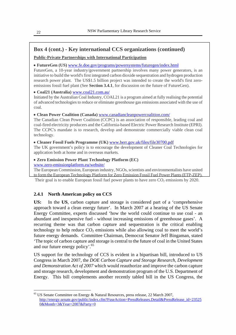
Box 4 (cont.) - Key international CCS organizations (continued) Public-Private Partnerships with International Participation
• FutureGen (US) www.fe.doe.gov/programs/powersystems/futuregen/index.html FutureGen, a 10-year industry/government partnership involves many power generators, is an initiative to build the world's first integrated carbon dioxide sequestration and hydrogen production research power plant. The US$1.5 billion project was intended to create the world's first zero-emissions fossil fuel plant (See Section 3.4.1, for discussion on the future of FutureGen). • Coal21 (Australia) www.coal21.com.au/ Initiated by the Australian Coal Industry, COAL21 is a program aimed at fully realising the potential of advanced technologies to reduce or eliminate greenhouse gas emissions associated with the use of coal.
• Clean Power Coalition (Canada) www.canadiancleanpowercoalition.com/ The Canadian Clean Power Coalition (CCPC) is an association of responsible, leading coal and coal-fired electricity producers and the California-based Electric Power Research Institute (EPRI). The CCPC's mandate is to research, develop and demonstrate commercially viable clean coal technology.
• Cleaner Fossil Fuels Programme (UK) www.berr.gov.uk/files/file30700.pdf The UK government’s policy is to encourage the development of Cleaner Coal Technologies for application both at home and in overseas markets.
• Zero Emission Power Plant Technology Platform (EC) www.zero-emissionplatform.eu/website/ The European Commission, European industry, NGOs, scientists and environmentalists have united to form the European Technology Platform for Zero Emission Fossil Fuel Power Plants (ETP-ZEP). Their goal is to enable European fossil fuel power plants to have zero CO2 emissions by 2020.
2.4.1 North American policy on CCS
US: In the US, carbon capture and storage is considered part of a ‘comprehensive approach toward a clean energy future’. In March 2007 at a hearing of the US Senate Energy Committee, experts discussed ‘how the world could continue to use coal - an abundant and inexpensive fuel - without increasing emissions of greenhouse gases’. A recurring theme was that carbon capture and sequestration is the critical enabling technology to help reduce CO2 emissions while also allowing coal to meet the world’s future energy demands. Committee Chairman, Democrat Senator Jeff Bingaman, stated ‘The topic of carbon capture and storage is central to the future of coal in the United States and our future energy policy’.65
US support for the technology of CCS is evident in a bipartisan bill, introduced to US Congress in March 2007, the DOE Carbon Capture and Storage Research, Development and Demonstration Act of 2007 which would reauthorize and improve the carbon capture and storage research, development and demonstration program of the U.S. Department of Energy. This bill complements another recently tabled bill in the US Congress, the
65 US Senate Committee on Energy & Natural Resources, press release, 22 March 2007,
http://energy.senate.gov/public/index.cfm?FuseAction=PressReleases.Detail&PressRelease_id=235250&Month=3&Year=2007&Party=0
Carbon Capture and Storage
23
National Carbon Dioxide Storage Capacity Assessment Act of 2007, which outlines a process for determining potential geological formations for the storage of carbon dioxide. Canada: For the past 15 years, Canada has been very active in exploring the opportunities for CCS, in developing and testing techniques and technologies to implement it, and in examining the associated policy, regulatory, environmental, and public education issues. Canada is now actively promoting the inclusion of CCS within the UNFCCC. To this end, a report was published in 2006 by the Office of Energy Research and Development of Natural Resources Canada to identify gaps, set priorities, and promote cooperation, and to inform Canada’s representatives in international discussions of the extent of Canada’s engagement in CCS activities, including scientific and engineering projects, and in projects that examine economic implementation, public education, and regulatory issues.66 In addition, the Canadian government has produced a CO2 capture and storage technology roadmap to identify technologies strategies, processes and integration system pathways needed to allow CO2 to be captured and stored in Canada.67 Canada has two CCS initiatives planned;68
• ICO2N (Integrated CO2 Network), a collaboration between the Alberta state government, the federal Canadian government, and a number of energy companies. It proposes to capture CO2 at an emissions source and transport it via pipeline to sites where it can be used for EOR (enhanced oil recovery) and permanently stored in depleted oil and gas fields or deep saline aquifers.
• ASAP (Alberta Saline Aquifer Project), a complementary project announced in Feb. 2008, by a group of 19 companies (some of whom are participating in both initiatives) to identify deep saline aquifers suitable for permanent storage of CO2 in Alberta.
2.4.2 UK policy on CCS
The UK government also supports carbon capture and storage and believes that the development and wide-scale deployment of CCS is important for its climate change and security of supply objectives. In May 2007 the UK Department of Trade & Industry (DTI) (now the Department for Business, Enterprise & Regulatory Reform), published its Energy White Paper.69 On the subject of CCS it noted the challenge of global reliance on coal versus reducing greenhouse gases:
Coal will continue to play a significant role in global electricity generation for the foreseeable future, partly because it is the most abundant global fossil fuel but also because it brings security of supply benefits. However, coal is more carbon intensive than oil or gas. The global challenge is therefore how to accelerate the deployment of technologies that allow us to continue to benefit from coal-fired power generation while reducing greenhouse gas emissions.
66 Carbon Dioxide Capture and Storage: A Compendium of Canada's Participation, Prepared for Office
of Energy Research and Development, Natural Resources Canada, January 2006 http://dsp-psd.pwgsc.gc.ca/Collection/M4-39-2006E.pdf
67 www.co2trm.gc.ca, www.nrcan.gc.ca/es/etb/cetc/combustion/co2trm/htmldocs/ccstrm_doc_challenges_e.html
68 http://www.ico2n.com/faqs.php 69 http://www.berr.gov.uk/energy/whitepaper/page39534.html
NSW Parliamentary Library Research Service
24
The UK White Paper suggests three options for reducing carbon emissions from fossil fuel fired power generation:
• improving coal-fired power station efficiency • co-firing coal with biomass • carbon capture and storage (CCS)
The UK Government provides financial support to CCS technologies. £35m has been allocated for the demonstration of Carbon Abatement Technologies, including Carbon Capture and Storage. A further £20m a year is being provided to support clean energy technologies under the Technology Strategy Programme for domestic industries. Financial support has also been pledged for a full commercial-scale CCS demonstration plant to be operational by 2014, within the second Kyoto commitment period. To this end, in March 2007 the then Chancellor, Gordon Brown, announced that the UK government would launch a competition to develop the UK’s first full-scale demonstration of carbon capture and storage.70
Through the G8, EU and bilaterally, the UK is also encouraging the deployment of CCS elsewhere - particularly in developing countries such as China and India with their rapidly growing energy needs. The UK collaborates with these major emerging economies through the ongoing work of the EU-China Near-Zero Emissions Coal Initiative signed in 2005. This initiative, supported by the UK and the European Commission, has the objective of demonstrating carbon capture and storage for power generation in China by 2020.71
2.4.3 EU policy on CCS
CCS is expected to have far-reaching implications for the industry sectors based on fossil fuels, both in the EU and worldwide. At the EU Heads of State Spring Council in March 2007, EU leaders called for the European Commission to develop a mechanism to stimulate the construction and operation of up to 12 demonstration plants by 2015, and for member states and the Commission to work towards the necessary technical, economic and regulatory framework to bring environmentally safe CCS to deployment in new fossil-fuel power plants, if possible by 2020.72
The European Commission is also preparing a legislative proposal which aims at establishing the regulatory framework for the capture of carbon dioxide and storage. To this end, during early 2007, the European Commission conducted a public internet consultation on CCS. The main objective was to consult citizens and other stakeholders on benefits and challenges of CCS, and how the CCS technology relates to other energy and greenhouse gas (GHG) mitigation options. Overall, the respondents expressed a moderate support for CCS. The majority agrees that CCS has a role to play in the energy mix and as a carbon mitigation option. Generally, the respondents view CCS as having a temporary/bridging role until long-term alternatives are developed and that CCS could provide CO2 reductions in addition to energy efficiency and renewable energy. These
70 http://www.hm-treasury.gov.uk./media/F/D/bud07_chapter7_273.pdf 71 http://www.defra.gov.uk/corporate/ministers/speeches/joan-ruddock/jr071003.htm 72 http://www.consilium.europa.eu/ueDocs/cms_Data/docs/pressData/en/ec/93135.pdf
Carbon Capture and Storage
25
views are being used to help the European Commission identify which issues to consider when preparing legislative proposals to regulate CCS.73
2.4.4 G8 policy on CCS
The G8 (Group of Eight) nations includes France, Germany, Italy, the United Kingdom, USA, Canada, Japan, and Russia. The G8 is able to help secure political commitment to action on key global issues as it involves the heads of government of the major economic powers, so their decisions can make a real impact.74 For example, the G8 represents about 65% of the world economy and about 45% of greenhouse gas emissions, so any consensus on the subject of climate change can potentially carry a great deal of weight.75 At the 2005 G8 summit, under the UK’s presidency, the main themes were Africa and climate change. The resulting Gleneagles Climate Change Plan of Action stated that G8 members would ‘work to accelerate the development and commercialization of CCS technology’ through measures such as:76
• endorsing the objectives and activities of the Carbon Sequestration Leadership Forum (CSLF)
• collaborating with key developing countries to research options for geological CO2 storage;
• working with industry and with national and international research programs and partnerships to explore the potential of CCS technologies, including with developing countries.
2.4.5 Asian policy on CCS China: China's CO2 emissions from coal fired power generation are set to double by 2030. In view of the essential role of coal in China's energy system, both China and the international community recognize that it is vital to minimise emissions where coal is used. China supports carbon capture and storage (CCS) technologies, and was one of the initiating parties to the international Carbon Sequestration Leadership Forum (CSLF). China is participating in numerous national and international CCS related activities:77
• Several academic institutes are researching carbon capture technologies. • Several EOR (Enhanced Oil Recovery) projects have been implemented. • China is cooperating with Canada in an ECBM (Enhanced Coal Bed Methane)
project. • In August 2005, GCEP (Global Climate and Energy Project) international
workshop on Clean Coal Technology Development was held in Beijing, China. Around 150 foreign and domestic experts gathered together to discuss CCS technologies;
• In 2005, CCS was integrated into the Chinese Government’s National Medium and Long-term Science and Technology Development Plan towards 2020.
• China is participating into the EUF6 ‘Geocapacity Project’. In this project, a specific 73 http://ec.europa.eu/environment/climat/ccs/pdf/ccs_consultations.pdf 74 http://www.g8.gov.uk 75 http://www.climal.com/thirdstory.php 76 http://www.fco.gov.uk/Files/kfile/PostG8_Gleneagles_CCChangePlanofAction.pdf 77 http://cslforum.org/documents/ChinaCCS.pdf

NSW Parliamentary Library Research Service
26
area will be selected to assess storage potential and mapping of sources and sinks. • MOST (Chinese Ministry of Science and Technology) are discussing with the EU
for a ten-year cooperation project on CCS, with strong support from the EU.
In November 2007 the British Geological Survey attended the launch of the Near Zero Emissions Coal (NZEC) study in Beijing, China. The aim of this study is to look at the feasibility of building coal fired power plants in China fitted with CO2 capture and storage (CCS). NZEC is funded by the UK Government through Defra and DBERR and is co-ordinated by AEA Energy & Environment (UK) and ACCA21, the Chinese government’s White Paper on population, environment and development in the 21st century.78
Japan: The Japanese Ministry of Economy, Trade and Industry (METI), has supported technical research and regulatory framework development for CCS since the mid-1990s. Japan also participates in international CCS projects, and is a member of the Asia-Pacific Partnership on Clean Development and Climate (AP6) and the Carbon Sequestration Leadership Forum (CSLF). In 2000, Japan initiated a pilot CO2 geological storage program, the Nagaoka project, a combined gas production and CO2 injection project. This was a collaborative program between the government, academic research institutes, oil companies, and the electricity generation industry in Japan.79
Between June 2003 and January 2005, 10,400 tonnes CO2 were successfully injected into a saline aquifer at 1,100m depth. This Nagaoka project achieved basic knowledge of aquifer storage in Japan. However, major challenges for CCS implementation in Japan include identification of appropriate storage sites, and cost reduction. The best CO2 storage sites are located in limited areas of Japan, and many of them are not close to large emission sources. The CCS Working Group of METI concluded in October 2007 that a large scale demonstration test is necessary as the next step towards practical implementation of CCS in Japan. A zero-emission coal fired power plant feasibility study is also under consideration.80 The Japanese government has recently set a national target to reduced CO2 emissions by 200 million tonnes annually (i.e. one sixth of annual emissions) through CCS technologies.81
India: India joined the CSLF in 2003 lead by the Indian Ministry of Power. The objective of Indian participation is to develop cost-effective technologies by organizing collaborative R&D. Like China and Japan, India currently participates in a number of international CCS activities:82
• Member of Asia Pacific Partnership in Clean Development • Signed an agreement with US Government in April 2006 for partnership in
FutureGen zero emission power plant • Institutional partner in BIG SKY Carbon Sequestration Partnership83 • Collaborative research on basalt rock studies under a CSLF project initiated with
USA. The results on mineral trapping studies will be useful for other countries with similar formations.
78 http://www.sciencedaily.com/releases/2007/11/071120104545.htm 79 http://www.rite.or.jp/Japanese/labo/choryu/workshop/futuregenws2008/2008FGWS_MrITO.pdf 80 http://www.un.org/esa/sustdev/sdissues/energy/op/ccs_egm/presentations_papers/akai_japan.pdf 81 http://search.japantimes.co.jp/cgi-bin/nb20060620a2.html 82 http://unfccc.int/files/meetings/sb24/in-session/application/pdf/un.ccs.mg.20.5.pdf 83 www.bigskyco2.org/

Carbon Capture and Storage
27
• Feasibility studies in oil fields for enhanced recovery and saline aquifers • Scientific institutions are engaged in CCS research and technical workshops to
disseminate knowledge and create awareness.
NSW Parliamentary Library Research Service
28
3 CARBON CAPTURE & STORAGE (CCS) TECHNOLOGY
There are three components to carbon dioxide capture and storage: 1. Capture - by concentrating, separating and capturing the CO2 from mixed flue gases; 2. Transport – usually via pipeline 3. Storage – involving compressing the CO2 to a liquid, injecting it underground and
monitoring the storage site. Although each of these individual components of the CCS chain operate at a commercial scale, it is important to note that the full process chain, that is, capture from a point source, transport to a suitable site, and injection and storage, has not yet been demonstrated anywhere in the world.
3.1 CO2 CAPTURE
The purpose of CO2 capture technologies is to produce a concentrated stream of CO2 at high pressure that can be readily transported to a storage site. The main problem with capturing CO2 from power stations is the large volume of flue gas and the low concentration of CO2 in the flue gas. CO2 makes up about 14% by volume of the flue gas from a conventional PF coal-fired power station, and only 4% of the flue gas from a gas-fired power station.84 In principle, the entire exhaust gas stream, containing only low concentrations of CO2 could be transported and injected underground. However, the cost of doing so makes this approach impractical. It is therefore necessary to produce a nearly pure CO2 stream for transport and storage.85 The more concentrated the stream of CO2 is in the flue gases, the cheaper and easier it is to separate and capture.
3.1.1 Concentrating the CO2 The concentration and pressure of CO2 in the gas emission stream, and the fuel type (solid or gas), are important factors in choosing the capture system. There are three main approaches to CO2 capture for industrial and power plant applications:
a) Post-combustion b) Pre-combustion c) Oxy-fuel combustion
a) Post-combustion capture • Capture of CO2 from flue gases from combustion of fossil fuels or biomass in air. • Used in conventional plants with dilute CO2 streams (typically 3-15% by volume)
Post combustion capture is already used to capture CO2 from flue gases from a number of existing power plants, and the separation of CO2 from natural gas in the gas processing industry is a mature technology. Instead of being discharged directly to the atmosphere, flue gas is passed through equipment which separates most of the CO2. A chemical sorbent process (see Section 3.1.2), is normally used to separate the CO2 from the other flue gases.86
84 Saddler H., Reidy, C. & Passey, R., (2004), Geosequestration. What it is and how much can it contribute to
a sustainable energy policy for Australia? The Australia Institute Discussion Paper No. 72, http://www.tai.org.au/documents/downloads/DP72.pdf
85 IPCC Special Report, Carbon Dioxide Capture and Storage, (2005), Summary for Policymakers and Technical Summary, p22, (www.ipcc.ch)
86 IPCC Special Report, Carbon Dioxide Capture and Storage, (2005), Chapter 3, Capture of CO2, p109
Carbon Capture and Storage
29
b) Pre-combustion capture • Coal is gasified to create a ‘syngas’ (a mixture of hydrogen, H2 and carbon
monoxide, CO) • The syngas has a relatively high purity CO2 waste gas stream (typically 15-60% by
volume) Although the initial fuel conversion steps are more complicated and costly, the higher concentrations of CO2 in the gas stream and the higher pressure make separation easier.87 If the CO2 is stored, the hydrogen is a carbon-free energy carrier that can be combusted to generate power. Pre-combustion would be used at power plants that employ integrated gasification combined cycle technology. The technology required for pre-combustion capture is already widely applied in fertilizer manufacture and in hydrogen production.
c) Oxy-fuel combustion • Uses oxygen instead of air for combustion • Produces a primarily CO2 exhaust gas stream (typically 55-90% by volume). • However, this technology option is still under development.
Instead of air, a relatively pure stream of oxygen is used to burn the coal, which results in a CO2-rich flue gas. A typical oxy-fuel combustion process would give CO2 concentrations of 55 to 65% in the flue gas, although concentrations greater than 90% are feasible at very high oxygen concentrations. These concentrations make CO2 capture much simpler and cheaper. Oxy-fuel combustion is considered one of the most promising technologies for retrofits of existing power stations, however, this technology is still experimental and has not yet been demonstrated commercially. The main problems are the cost and the energy consumption associated with making the oxygen. The additional energy required to generate oxygen outweighs the improvement in boiler efficiency.88
3.1.2 Separating and capturing the CO2
Once a relatively concentrated stream of CO2 is achieved, there are several mature technologies available to capture and separate CO2 from the flue gases. These include:
i. sorbent/solvent scrubbing; ii. cryogenics; and
iii. membranes.
i) Sorbent/solvent scrubbing systems Dilute concentrations of CO2 can be removed from flue gases using solvents that rely on chemical or physical absorption. The most common solvents used for post-combustion removal of CO2 from flue gases are ‘amines’ - the technology is referred to as ‘amine scrubbing’.89 Amines are derivatives of ammonia, and act as a weak base (the opposite of acid), to neutralise CO2. The flue gas is brought into contact with a solution of amine and water. The amine and the CO2 undergo a chemical reaction forming a rich amine that is soluble in the water. The rich
http://arch.rivm.nl/env/int/ipcc/pages_media/SRCCS-final/SRCCS_Chapter3.pdf 87 See Footnote 85, IPCC CCS Special Report Summary, p4 88 Saddler H., Reidy, C. & Passey, R., (2004), Geosequestration. What it is and how much can it contribute
to a sustainable energy policy for Australia? The Australia Institute Discussion Paper No. 72, http://www.tai.org.au/documents/downloads/DP72.pdf
89 http://www.climatetechnology.gov/library/2003/tech-options/tech-options-3-1-1.pdf
NSW Parliamentary Library Research Service
30
amine solution is pumped to a desorber where it is heated, reversing the reaction and releasing pure CO2 gas. The recovered amine is then sent back to the original vessel to capture more CO2 in a cyclical process. The separated CO2 is then fed to a storage reservoir and the remaining flue gases, (nitrogen, oxygen, water vapour), are vented to the atmosphere. 90
One common problem of these CO2 capture systems is that the flow of solvent between containers is large because it has to match the huge flow of CO2 being processed in the power plant. Therefore, equipment sizes and the energy required for solvent recycling are large and translate into an efficiency penalty and added cost of expensive solvent materials. However, solvent scrubbing is a very effective method of capturing CO2 from flue gases, and can achieve a CO2 recovery rate of up to 98%.91
ii) Cryogenic separation of CO2
A gas can be made liquid by a series of compression, cooling and expansion steps. Cryogenic processes use cooling and condensation to separate CO2 from other gaseous compounds, relying on differences in the boiling points of gases. Once in liquid form, the components of the gas can be separated in a distillation column. It is mainly used for purification of gas streams that already contain a high concentration of CO2 (greater than 90%), and has not been applied to dilute flue gases. For this reason, this CO2 separation system is better suited to oxy-fuel combustion plants. This process is currently carried out commercially on a large scale to separate oxygen from air. Cryogenic CO2 separation is energy intensive, and significantly reduces the energy efficiency of a power plant.92
iii) Membranes
Membranes are specially manufactured materials that allow the selective permeation of a gas through them. The selectivity of the membrane to different gases is related to the nature of the material, and the flow of gas through the membrane is driven by the pressure difference across the membrane. Therefore, high-pressure streams are usually preferred for membrane separation. There are many different types of membrane materials (polymer, metallic, ceramic) that may find application in CO2 capture systems. Although membrane separation finds many current commercial applications in industry (for example, CO2 separation from natural gas) it has not yet been applied for the large scale and demanding conditions in terms of reliability and low-cost required for CO2 capture systems.93
90 IPCC Special Report, Carbon Dioxide Capture and Storage, (2005), Chapter 3, Capture of CO2, p109
http://arch.rivm.nl/env/int/ipcc/pages_media/SRCCS-final/SRCCS_Chapter3.pdf 91 See footnote 88. 92 See footnotes 88 and 90. 93 IPCC Special Report, Carbon Dioxide Capture and Storage, (2005), Chapter 3, Capture of CO2, p109
http://arch.rivm.nl/env/int/ipcc/pages_media/SRCCS-final/SRCCS_Chapter3.pdf
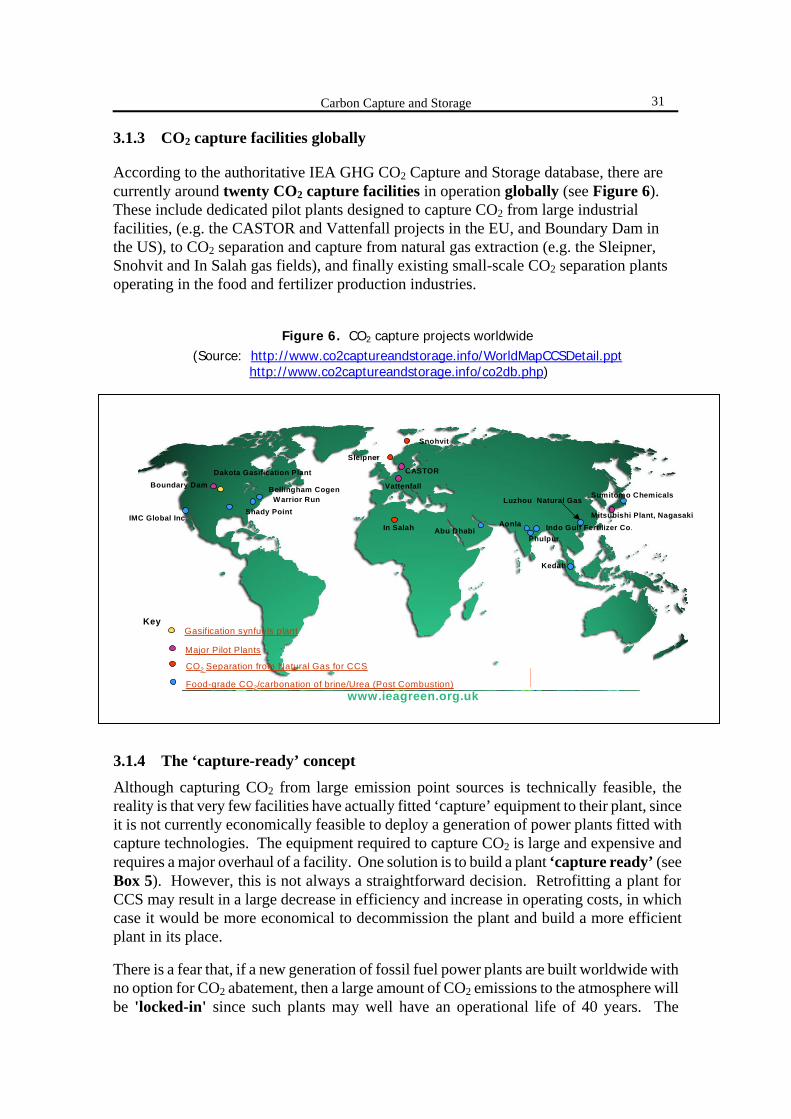
Carbon Capture and Storage
31
3.1.3 CO2 capture facilities globally
According to the authoritative IEA GHG CO2 Capture and Storage database, there are currently around twenty CO2 capture facilities in operation globally (see Figure 6). These include dedicated pilot plants designed to capture CO2 from large industrial facilities, (e.g. the CASTOR and Vattenfall projects in the EU, and Boundary Dam in the US), to CO2 separation and capture from natural gas extraction (e.g. the Sleipner, Snohvit and In Salah gas fields), and finally existing small-scale CO2 separation plants operating in the food and fertilizer production industries.
There is a fear that, if a new generation of fossil fuel power plants are built worldwide with no option for CO2 abatement, then a large amount of CO2 emissions to the atmosphere will be 'locked-in' since such plants may well have an operational life of 40 years. The
www.ieagreen.org.uk
CO2 Capture FacilitiesCO2 Capture Facilities
Mitsubishi Plant, Nagasaki
Sumitomo Chemicals
Indo Gulf Fertilizer Co.
Luzhou Natural Gas
Vattenfall
CASTOR
Snohvit
Sleipner
In Salah
Shady Point
Bellingham Cogen
Dakota Gasification PlantBoundary Dam
IMC Global Inc.
Key
Warrior Run
Gasification synfuels plant
Major Pilot Plants
CO2 Separation from Natural Gas for CCS
Food-grade CO2/carbonation of brine/Urea (Post Combustion)
Kedah
How to use this Presentation
Back to main menu
Abu DhabiAonla
Phulpur
Figure 6. CO2 capture projects worldwide
(Source: http://www.co2captureandstorage.info/WorldMapCCSDetail.ppt http://www.co2captureandstorage.info/co2db.php)
3.1.4 The ‘capture-ready’ concept
Although capturing CO2 from large emission point sources is technically feasible, the reality is that very few facilities have actually fitted ‘capture’ equipment to their plant, sinceit is not currently economically feasible to deploy a generation of power plants fitted withcapture technologies. The equipment required to capture CO2 is large and expensive and requires a major overhaul of a facility. One solution is to build a plant ‘capture ready’ (see Box 5). However, this is not always a straightforward decision. Retrofitting a plant for CCS may result in a large decrease in efficiency and increase in operating costs, in whichcase it would be more economical to decommission the plant and build a more efficientplant in its place.

NSW Parliamentary Library Research Service
32
underlying purpose therefore, of making a plant ‘capture-ready’, is to facilitate retrofitting carbon dioxide capture to that plant in the future to avoid future ‘carbon lock-in’, both at a plant and a national (and global) level. However, the additional costs and actions required to build a capture-ready facility and the subsequent retrofit costs are expected to be significant barriers to its adoption.
Box 5 - Definition of ‘capture-ready’
In May 2007, the IEA GHG research programme published a study on CO2 capture ready plants, and produced the following definition of ‘capture ready’:94
A CO2 capture ready power plant is a plant which can include CO2 capture when the necessary regulatory or economic drivers are in place.
Another 2007 paper by the sequestration research group at MIT defines ‘capture ready’ by the following:95
A plant can be considered ‘capture-ready’ if, at some point in the future it can be retrofitted for carbon capture and sequestration and still be economical to operate.
Some of the issues that face owners considering retrofitting their plants for CCS include:96 • Physical space required for new equipment.
The key requirement of a capture-ready design is the provision of space for the CO2 capture equipment (scrubbers, CO2 compressors, oxygen production plant etc.), additional infrastructure including cooling water and electrical systems, safety barrier zones, pipework and tie-ins to existing equipment. Further space may be needed during construction, for storage of equipment and materials and for access to the existing plant.
• Large reduction in the net electrical output of the plant (i.e. ‘efficiency penalty’) Retrofitting CO2 capture technology to a conventional post-combustion coal-fired plant would reduce the net power output by about 20-25%, due to the diversion of significant amounts of steam to the re-boilers of the amine CO2 recovery system and the need for electric power to drive the CO2 compressors. For oxy-fired power plants, the power requirements of the air separation unit consumes ~20% of the generator output.
• Location and access to a suitable sequestration site. The concentrated CO2 has to be compressed (liquefied) and eventually transported to the final storage location or consumption point. Ideally, the plant will be located near an existing CO2 pipeline infrastructure or storage site. However, plant integration with the electric grid and access to cooling water are currently of greater importance than the location of the plant for proximity to a storage site or existing pipeline.
• Increased operation and maintenance costs. • Capital costs and the associated financing of the capture equipment. • Increased total and variable cost of electricity. • Timing and length of the downtime required for the retrofit.
94 http://www.iea.org/Textbase/Papers/2007/CO2_Capture_Ready_plants.pdf 95 http://sequestration.mit.edu/pdf/capture-ready_coal_plants-options_technologies.pdf 96http://www.eppsa.org/en/upload/File/Events/EPPSA%20Technology%20Evening%202006/EPPSA%20Capt
ure%20Ready%20Definition.pdf (European Power Plant Suppliers Association) CO2 Capture Ready Recommendations, 7/12/2006
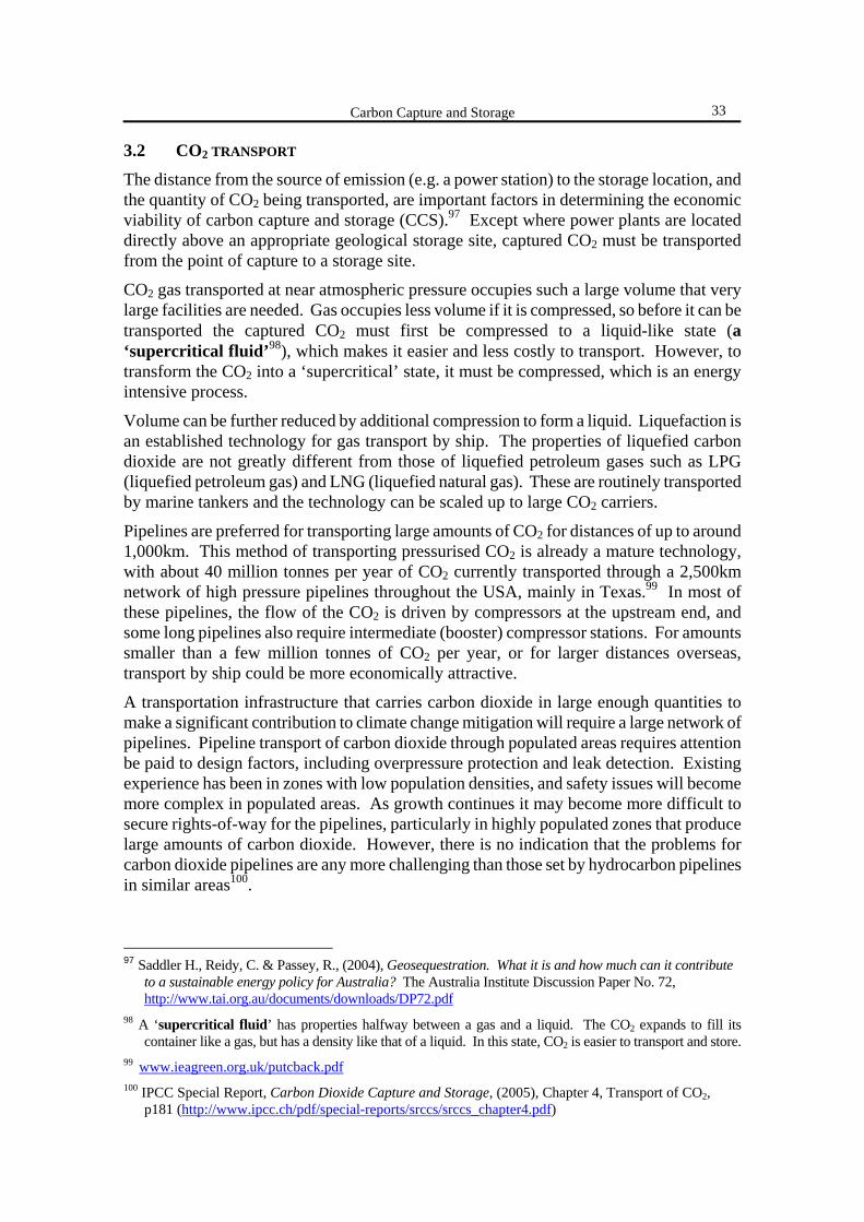
Carbon Capture and Storage
33
3.2 CO2 TRANSPORT
The distance from the source of emission (e.g. a power station) to the storage location, and the quantity of CO2 being transported, are important factors in determining the economic viability of carbon capture and storage (CCS).97 Except where power plants are located directly above an appropriate geological storage site, captured CO2 must be transported from the point of capture to a storage site.
CO2 gas transported at near atmospheric pressure occupies such a large volume that very large facilities are needed. Gas occupies less volume if it is compressed, so before it can be transported the captured CO2 must first be compressed to a liquid-like state (a ‘supercritical fluid’98), which makes it easier and less costly to transport. However, to transform the CO2 into a ‘supercritical’ state, it must be compressed, which is an energy intensive process.
Volume can be further reduced by additional compression to form a liquid. Liquefaction is an established technology for gas transport by ship. The properties of liquefied carbon dioxide are not greatly different from those of liquefied petroleum gases such as LPG (liquefied petroleum gas) and LNG (liquefied natural gas). These are routinely transported by marine tankers and the technology can be scaled up to large CO2 carriers.
Pipelines are preferred for transporting large amounts of CO2 for distances of up to around 1,000km. This method of transporting pressurised CO2 is already a mature technology, with about 40 million tonnes per year of CO2 currently transported through a 2,500km network of high pressure pipelines throughout the USA, mainly in Texas.99 In most of these pipelines, the flow of the CO2 is driven by compressors at the upstream end, and some long pipelines also require intermediate (booster) compressor stations. For amounts smaller than a few million tonnes of CO2 per year, or for larger distances overseas, transport by ship could be more economically attractive.
A transportation infrastructure that carries carbon dioxide in large enough quantities to make a significant contribution to climate change mitigation will require a large network of pipelines. Pipeline transport of carbon dioxide through populated areas requires attention be paid to design factors, including overpressure protection and leak detection. Existing experience has been in zones with low population densities, and safety issues will become more complex in populated areas. As growth continues it may become more difficult to secure rights-of-way for the pipelines, particularly in highly populated zones that produce large amounts of carbon dioxide. However, there is no indication that the problems for carbon dioxide pipelines are any more challenging than those set by hydrocarbon pipelines in similar areas100.
97 Saddler H., Reidy, C. & Passey, R., (2004), Geosequestration. What it is and how much can it contribute
to a sustainable energy policy for Australia? The Australia Institute Discussion Paper No. 72, http://www.tai.org.au/documents/downloads/DP72.pdf
98 A ‘supercritical fluid’ has properties halfway between a gas and a liquid. The CO2 expands to fill its container like a gas, but has a density like that of a liquid. In this state, CO2 is easier to transport and store.
99 www.ieagreen.org.uk/putcback.pdf 100 IPCC Special Report, Carbon Dioxide Capture and Storage, (2005), Chapter 4, Transport of CO2,
p181 (http://www.ipcc.ch/pdf/special-reports/srccs/srccs_chapter4.pdf)

NSW Parliamentary Library Research Service
34
Pipeline transport is of particular relevance in Australia where distances from ‘source to sink’ are relatively large. As yet, no CO2 transport pipelines have yet been built in Australia. However, several Australian states including South Australia, Western Australia and Queensland have amended their petroleum legislation to include CO2 as a regulated substance which can be transported by pipeline.101.
3.3 CO2 STORAGE
Captured CO2 would need to be stored securely for hundreds or even thousands of years, in order to avoid it reaching the atmosphere.102 There are four main scientifically viable options for the long term storage of CO2:
1) Geological storage (geosequestration); 2) Deep ocean storage; 3) Solid storage (transform CO2 to solid mineral carbonates); 4) Use in industrial processes.
Geological storage of CO2 is seen as the most promising storage option capable of achieving deep reductions in the foreseeable future.
3.3.1 Geological storage (geosequestration)
Geological storage of CO2 involves injection of compressed CO2 into the subsurface, down to a storage depth of 800 to 1,000 metres. The CO2 is compressed (at the surface) to a dense ‘supercritical’ state103 - a state where the CO2 adopts properties half-way between a gas and a liquid. In this state it is very much denser than gaseous CO2. It has a liquid-like density, but also flows like a gas through the pore spaces of rocks. So, it has the ability to diffuse through solids like a gas, and dissolve materials like a liquid. This dense physical state of the CO2, and the pressure and temperature at these depths, means that the CO2 would be prevented from migrating back to the surface.104 Compressing the CO2 also reduces its volume and means the volume of underground storage required is smaller.
Underground storage of CO2 has taken place for many years as a consequence of injecting CO2 into oil fields to enhance oil recovery. Provided the injection site is carefully chosen the CO2 will remain stored for very long periods of time and can be monitored.105 Most of the CO2 initially remains in a stable supercritical state. Over time some of the CO2 may react with the bedrock to form solid carbonate minerals, and some will dissolve into the pore-water within the bedrock.
There are a number of potential geological formations that can be used to store captured CO2 (See Figure 7). The effectiveness of geological storage depends on a combination of physical and geochemical trapping mechanisms. The most effective storage sites are those 101 http://gasweek.wordpress.com/2007/09/19/co2-dump-rules-in-south-australia-western-australia-and-
queensland-none-appear-to-deal-with-earthquake-water-quality-or-leak-risks-or-long-term-liability/ 102 http://www.co2captureandstorage.info/what_is_co2.php 103 See Section 3.2: CO2 Transport for definition of ‘supercritical’. 104 IPCC Special Report, Carbon Dioxide Capture and Storage, (2005), Summary for Policymakers and
Technical Summary, p5, (www.ipcc.ch) 105 http://www.coal21.com.au/CO2capstore.php
Carbon Capture and Storage
35
where CO2 is trapped permanently under a thick, low-permeability seal, or is converted to solid minerals, or is adsorbed on the surfaces of coal micropores. Sedimentary basins have such closed, physically bound traps or structures, which are occupied mainly by saline water, oil and gas. Many of these geological traps have already held hydrocarbons or liquids for many millions of years. The following three geological structures are the most feasible for the large-scale storage of CO2:106
a) Depleted and disused oil and gas fields - including for enhanced oil/gas recovery (EOR);
b) Deep saline aquifers - onshore and offshore; c) Deep unminable coal seams - including for enhanced coalbed methane recovery
(ECBM).
Figure 7. Overview of the three main geological (geosequestration) storage options.
(Source: http://www.co2crc.com.au/imagelibrary/SPM_storageoptions.jpg)
106 http://www.ieagreen.org.uk/ccs.html
a) depleted oil/gas
reservoir a) enhanced oil/gas
recovery (EOR)
b) offshore saline aquifer
c) enhanced coal bed methane
(ECBM)
Overview of Geological Storage Options
a) Depleted oil & gas reservoirs - including use of CO2 for enhanced oil/gas recovery (EOR) b) Deep saline aquifers (offshore & onshore) c) Deep unmineable coal seams - including use of CO2 for enhanced coal bed methane recovery (ECBM)
b) onshoresaline aquifer
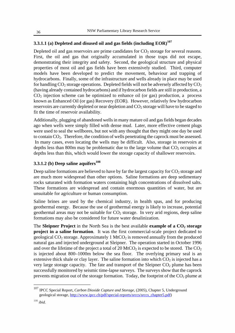
NSW Parliamentary Library Research Service
36
3.3.1.1 (a) Depleted and disused oil and gas fields (including EOR)107
Depleted oil and gas reservoirs are prime candidates for CO2 storage for several reasons. First, the oil and gas that originally accumulated in those traps did not escape, demonstrating their integrity and safety. Second, the geological structure and physical properties of most oil and gas fields have been extensively studied. Third, computer models have been developed to predict the movement, behaviour and trapping of hydrocarbons. Finally, some of the infrastructure and wells already in place may be used for handling CO2 storage operations. Depleted fields will not be adversely affected by CO2 (having already contained hydrocarbons) and if hydrocarbon fields are still in production, a CO2 injection scheme can be optimized to enhance oil (or gas) production, a process known as Enhanced Oil (or gas) Recovery (EOR). However, relatively few hydrocarbon reservoirs are currently depleted or near depletion and CO2 storage will have to be staged to fit the time of reservoir availability.
Additionally, plugging of abandoned wells in many mature oil and gas fields began decades ago when wells were simply filled with dense mud. Later, more effective cement plugs were used to seal the wellbores, but not with any thought that they might one day be used to contain CO2. Therefore, the condition of wells penetrating the caprock must be assessed. In many cases, even locating the wells may be difficult. Also, storage in reservoirs at depths less than 800m may be problematic due to the large volume that CO2 occupies at depths less than this, which would lower the storage capacity of shallower reservoirs.
3.3.1.2 (b) Deep saline aquifers108
Deep saline formations are believed to have by far the largest capacity for CO2 storage and are much more widespread than other options. Saline formations are deep sedimentary rocks saturated with formation waters containing high concentrations of dissolved salts. These formations are widespread and contain enormous quantities of water, but are unsuitable for agriculture or human consumption.
Saline brines are used by the chemical industry, in health spas, and for producing geothermal energy. Because the use of geothermal energy is likely to increase, potential geothermal areas may not be suitable for CO2 storage. In very arid regions, deep saline formations may also be considered for future water desalinization.
The Sleipner Project in the North Sea is the best available example of a CO2 storage project in a saline formation. It was the first commercial-scale project dedicated to geological CO2 storage. Approximately 1 MtCO2 is removed annually from the produced natural gas and injected underground at Sleipner. The operation started in October 1996 and over the lifetime of the project a total of 20 MtCO2 is expected to be stored. The CO2 is injected about 800–1000m below the sea floor. The overlying primary seal is an extensive thick shale or clay layer. The saline formation into which CO2 is injected has a very large storage capacity. The fate and transport of the Sleipner CO2 plume has been successfully monitored by seismic time-lapse surveys. The surveys show that the caprock prevents migration out of the storage formation. Today, the footprint of the CO2 plume at
107 IPCC Special Report, Carbon Dioxide Capture and Storage, (2005), Chapter 5, Underground
geological storage, http://www.ipcc.ch/pdf/special-reports/srccs/srccs_chapter5.pdf) 108 ibid.
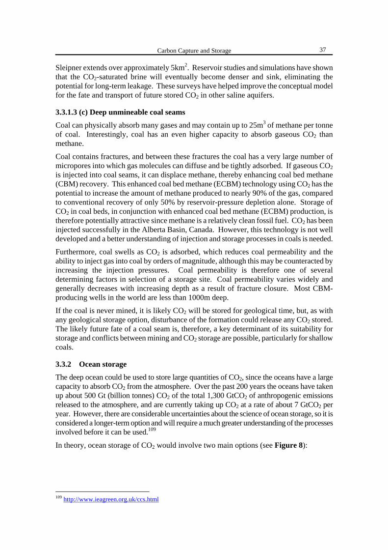
Carbon Capture and Storage
37
Sleipner extends over approximately 5km2. Reservoir studies and simulations have shown that the CO2-saturated brine will eventually become denser and sink, eliminating the potential for long-term leakage. These surveys have helped improve the conceptual model for the fate and transport of future stored CO2 in other saline aquifers.
3.3.1.3 (c) Deep unmineable coal seams
Coal can physically absorb many gases and may contain up to 25m3 of methane per tonne of coal. Interestingly, coal has an even higher capacity to absorb gaseous CO2 than methane.
Coal contains fractures, and between these fractures the coal has a very large number of micropores into which gas molecules can diffuse and be tightly adsorbed. If gaseous CO2 is injected into coal seams, it can displace methane, thereby enhancing coal bed methane (CBM) recovery. This enhanced coal bed methane (ECBM) technology using CO2 has the potential to increase the amount of methane produced to nearly 90% of the gas, compared to conventional recovery of only 50% by reservoir-pressure depletion alone. Storage of CO2 in coal beds, in conjunction with enhanced coal bed methane (ECBM) production, is therefore potentially attractive since methane is a relatively clean fossil fuel. CO2 has been injected successfully in the Alberta Basin, Canada. However, this technology is not well developed and a better understanding of injection and storage processes in coals is needed.
Furthermore, coal swells as CO2 is adsorbed, which reduces coal permeability and the ability to inject gas into coal by orders of magnitude, although this may be counteracted by increasing the injection pressures. Coal permeability is therefore one of several determining factors in selection of a storage site. Coal permeability varies widely and generally decreases with increasing depth as a result of fracture closure. Most CBM-producing wells in the world are less than 1000m deep.
If the coal is never mined, it is likely CO2 will be stored for geological time, but, as with any geological storage option, disturbance of the formation could release any CO2 stored. The likely future fate of a coal seam is, therefore, a key determinant of its suitability for storage and conflicts between mining and CO2 storage are possible, particularly for shallow coals.
3.3.2 Ocean storage
The deep ocean could be used to store large quantities of CO2, since the oceans have a large capacity to absorb CO2 from the atmosphere. Over the past 200 years the oceans have taken up about 500 Gt (billion tonnes) CO2 of the total 1,300 GtCO2 of anthropogenic emissions released to the atmosphere, and are currently taking up CO2 at a rate of about 7 GtCO2 per year. However, there are considerable uncertainties about the science of ocean storage, so it is considered a longer-term option and will require a much greater understanding of the processes involved before it can be used.109
In theory, ocean storage of CO2 would involve two main options (see Figure 8):
109 http://www.ieagreen.org.uk/ccs.html
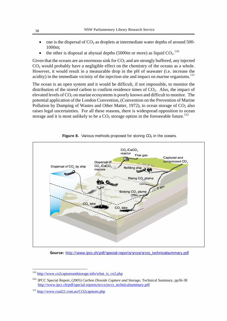
NSW Parliamentary Library Research Service
38
• one is the dispersal of CO2 as droplets at intermediate water depths of around 500-1000m;
• the other is disposal at abyssal depths (5000m or more) as liquid CO2.110
Given that the oceans are an enormous sink for CO2 and are strongly buffered, any injected CO2 would probably have a negligible effect on the chemistry of the oceans as a whole. However, it would result in a measurable drop in the pH of seawater (i.e. increase the acidity) in the immediate vicinity of the injection site and impact on marine organisms.111
The ocean is an open system and it would be difficult, if not impossible, to monitor the distribution of the stored carbon to confirm residence times of CO2. Also, the impact of elevated levels of CO2 on marine ecosystems is poorly known and difficult to monitor. The potential application of the London Convention, (Convention on the Prevention of Marine Pollution by Dumping of Wastes and Other Matter, 1972), to ocean storage of CO2 also raises legal uncertainties. For all these reasons, there is widespread opposition to ocean storage and it is most unlikely to be a CO2 storage option in the foreseeable future.112
110 http://www.co2captureandstorage.info/what_is_co2.php 111 IPCC Special Report, (2005) Carbon Dioxide Capture and Storage, Technical Summary, pp36-38
http://www.ipcc.ch/pdf/special-reports/srccs/srccs_technicalsummary.pdf 112 http://www.coal21.com.au/CO2capstore.php
Figure 8. Various methods proposed for storing CO2 in the oceans.
Source: http://www.ipcc.ch/pdf/special-reports/srccs/srccs_technicalsummary.pdf
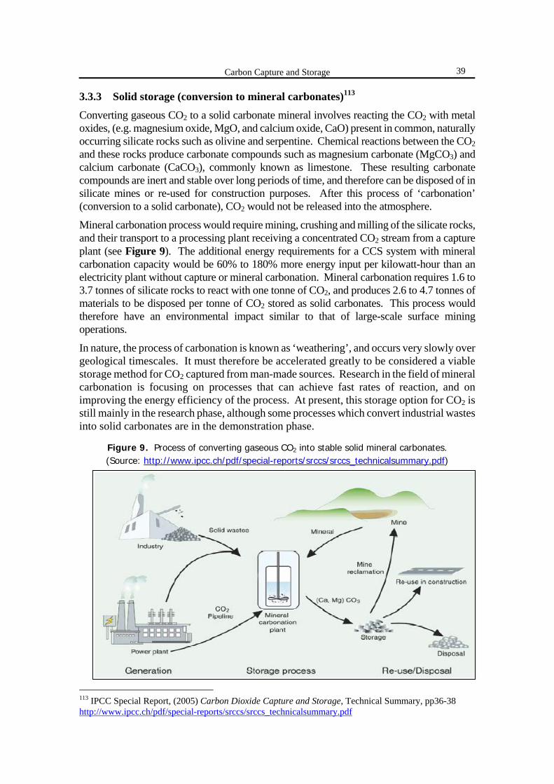
Carbon Capture and Storage
39
3.3.3 Solid storage (conversion to mineral carbonates)113
Converting gaseous CO2 to a solid carbonate mineral involves reacting the CO2 with metal oxides, (e.g. magnesium oxide, MgO, and calcium oxide, CaO) present in common, naturally occurring silicate rocks such as olivine and serpentine. Chemical reactions between the CO2 and these rocks produce carbonate compounds such as magnesium carbonate (MgCO3) and calcium carbonate (CaCO3), commonly known as limestone. These resulting carbonate compounds are inert and stable over long periods of time, and therefore can be disposed of in silicate mines or re-used for construction purposes. After this process of ‘carbonation’ (conversion to a solid carbonate), CO2 would not be released into the atmosphere.
Mineral carbonation process would require mining, crushing and milling of the silicate rocks, and their transport to a processing plant receiving a concentrated CO2 stream from a capture plant (see Figure 9). The additional energy requirements for a CCS system with mineral carbonation capacity would be 60% to 180% more energy input per kilowatt-hour than an electricity plant without capture or mineral carbonation. Mineral carbonation requires 1.6 to 3.7 tonnes of silicate rocks to react with one tonne of CO2, and produces 2.6 to 4.7 tonnes of materials to be disposed per tonne of CO2 stored as solid carbonates. This process would therefore have an environmental impact similar to that of large-scale surface mining operations.
In nature, the process of carbonation is known as ‘weathering’, and occurs very slowly over geological timescales. It must therefore be accelerated greatly to be considered a viable storage method for CO2 captured from man-made sources. Research in the field of mineral carbonation is focusing on processes that can achieve fast rates of reaction, and on improving the energy efficiency of the process. At present, this storage option for CO2 is still mainly in the research phase, although some processes which convert industrial wastes into solid carbonates are in the demonstration phase.
Figure 9. Process of converting gaseous CO2 into stable solid mineral carbonates. (Source: http://www.ipcc.ch/pdf/special-reports/srccs/srccs_technicalsummary.pdf)
113 IPCC Special Report, (2005) Carbon Dioxide Capture and Storage, Technical Summary, pp36-38 http://www.ipcc.ch/pdf/special-reports/srccs/srccs_technicalsummary.pdf

NSW Parliamentary Library Research Service
40
3.3.4 Use in industrial processes114
Industrial uses of CO2 include chemical and biological processes where CO2 is used as a reactant to produce urea (for fertilizers) and methanol, as well as in direct applications, for example, in refrigeration, food packaging, beverages, welding, fire extinguishers and in the horticultural industry. Currently CO2 is used for these applications at a rate of 120 Mt (million tonnes) per year worldwide.
These industrial uses of CO2 can, in principle, contribute to keeping CO2 out of the atmosphere by storing it in the ‘carbon chemical pool’. However, the typical lifetime of most of the CO2 currently used by industrial processes has storage times of only days to months. Such short timescales do not contribute meaningfully to climate change mitigation. In addition, the total industrial use figure of 120 MtCO2/year is small compared to annual emissions from major anthropogenic sources (~2,700 Mt). The IPCC therefore conclude that the contribution of industrial uses of captured CO2 to climate change mitigation is expected to be small.
114 IPCC Special Report, (2005) Carbon Dioxide Capture and Storage, Technical Summary, pp36-38
http://www.ipcc.ch/pdf/special-reports/srccs/srccs_technicalsummary.pdf
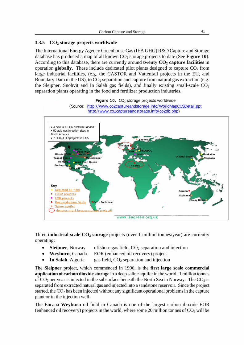
Carbon Capture and Storage
41
3.3.5 CO2 storage projects worldwide
The International Energy Agency Greenhouse Gas (IEA GHG) R&D Capture and Storage database has produced a map of all known CO2 storage projects to date (See Figure 10). According to this database, there are currently around twenty CO2 capture facilities in operation globally. These include dedicated pilot plants designed to capture CO2 from large industrial facilities, (e.g. the CASTOR and Vattenfall projects in the EU, and Boundary Dam in the US), to CO2 separation and capture from natural gas extraction (e.g. the Sleipner, Snohvit and In Salah gas fields), and finally existing small-scale CO2 separation plants operating in the food and fertilizer production industries. Three industrial-scale CO2 storage projects (over 1 million tonnes/year) are currently operating:
• Sleipner, Norway offshore gas field, CO2 separation and injection • Weyburn, Canada EOR (enhanced oil recovery) project • In Salah, Algeria gas field, CO2 separation and injection
The Sleipner project, which commenced in 1996, is the first large scale commercial application of carbon dioxide storage in a deep saline aquifer in the world. 1 million tonnes of CO2 per year is injected in the subsurface beneath the North Sea in Norway. The CO2 is separated from extracted natural gas and injected into a sandstone reservoir. Since the project started, the CO2 has been injected without any significant operational problems in the capture plant or in the injection well. The Encana Weyburn oil field in Canada is one of the largest carbon dioxide EOR (enhanced oil recovery) projects in the world, where some 20 million tonnes of CO2 will be
www.ieagreen.org.uk
COCO 22 Injection and Storage ActivitiesInjection and Storage Activities
Key
ECBM projects
EOR projects
Gas production Fields
Saline aquifier
West Pearl Queen
Depleted Oil Field
Back to main map
Figure 10. CO2 storage projects worldwide (Source: http://www.co2captureandstorage.info/WorldMapCCSDetail.ppt
http://www.co2captureandstorage.info/co2db.php)
•Cerro Fortunoso
Gorgon •
Otway Basin •Kwinana •
•In Salah
• Hokkaido • Nagaoko Qinshui Basin
•• Sibilla
•RECOPOL CO2 SINK •Sleipner •
• Snohvit
•K-12B
•Weyburn
•Frio •West Pearl Queen
•Carson
•Penn West
•Mountaineer
•Zama
Burlington •
Teapot Dome•Alberta ECBM •
Rangely•
• 4 new CO2-EOR pilots in Canada • 50 acid gas injection sites in North America • 70 CO2-EOR projects in USA
Key • Depleted oil field • ECBM projects • EOR projects • Gas production fields • Saline aquifer denotes the 3 largest storage projects
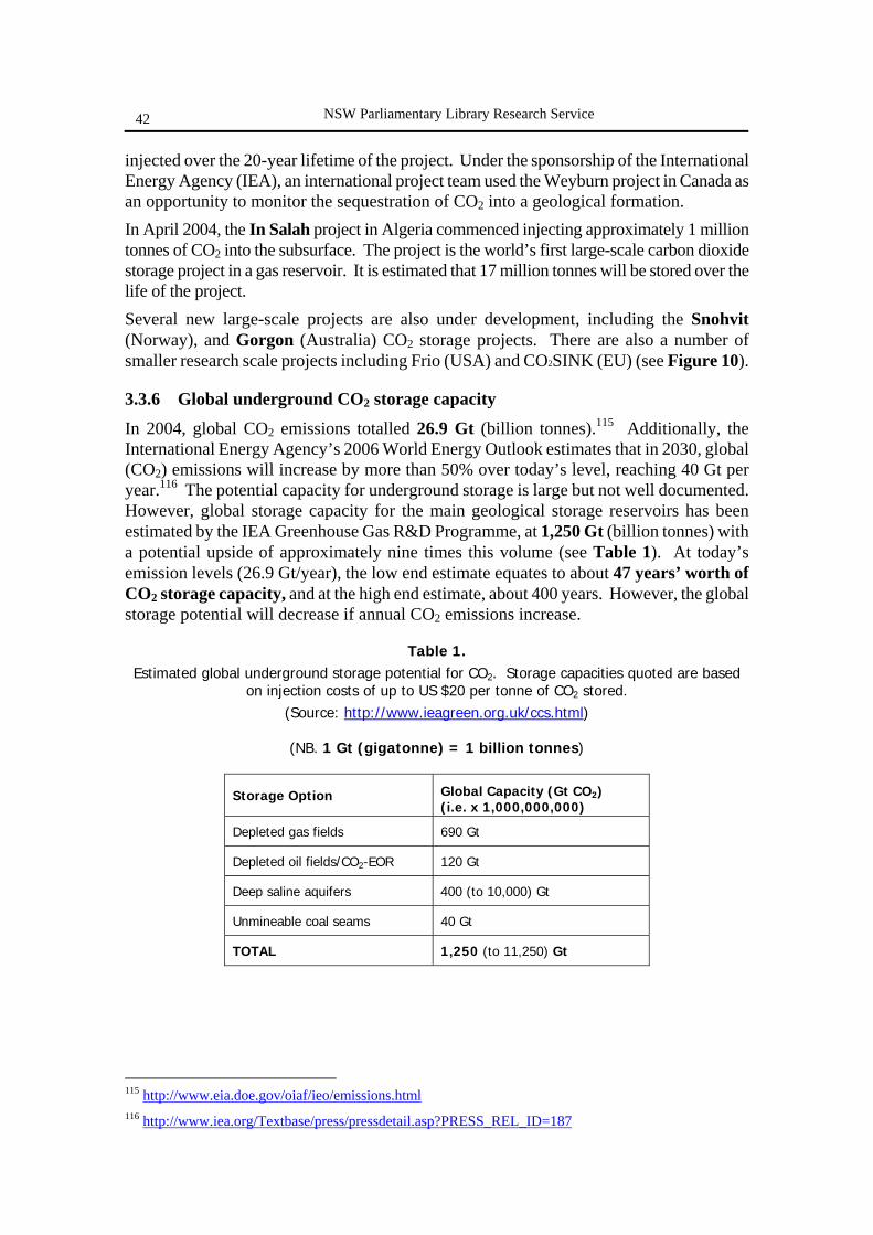
NSW Parliamentary Library Research Service
42
injected over the 20-year lifetime of the project. Under the sponsorship of the International Energy Agency (IEA), an international project team used the Weyburn project in Canada as an opportunity to monitor the sequestration of CO2 into a geological formation. In April 2004, the In Salah project in Algeria commenced injecting approximately 1 million tonnes of CO2 into the subsurface. The project is the world’s first large-scale carbon dioxide storage project in a gas reservoir. It is estimated that 17 million tonnes will be stored over the life of the project. Several new large-scale projects are also under development, including the Snohvit (Norway), and Gorgon (Australia) CO2 storage projects. There are also a number of smaller research scale projects including Frio (USA) and CO2SINK (EU) (see Figure 10).
3.3.6 Global underground CO2 storage capacity
In 2004, global CO2 emissions totalled 26.9 Gt (billion tonnes).115 Additionally, the International Energy Agency’s 2006 World Energy Outlook estimates that in 2030, global (CO2) emissions will increase by more than 50% over today’s level, reaching 40 Gt per year.116 The potential capacity for underground storage is large but not well documented. However, global storage capacity for the main geological storage reservoirs has been estimated by the IEA Greenhouse Gas R&D Programme, at 1,250 Gt (billion tonnes) with a potential upside of approximately nine times this volume (see Table 1). At today’s emission levels (26.9 Gt/year), the low end estimate equates to about 47 years’ worth of CO2 storage capacity, and at the high end estimate, about 400 years. However, the global storage potential will decrease if annual CO2 emissions increase.
Table 1. Estimated global underground storage potential for CO2. Storage capacities quoted are based
on injection costs of up to US $20 per tonne of CO2 stored. (Source: http://www.ieagreen.org.uk/ccs.html)
(NB. 1 Gt (gigatonne) = 1 billion tonnes)
Storage Option
Global Capacity (Gt CO2) (i.e. x 1,000,000,000)
Depleted gas fields 690 Gt
Depleted oil fields/CO2-EOR 120 Gt
Deep saline aquifers 400 (to 10,000) Gt
Unmineable coal seams 40 Gt
TOTAL 1,250 (to 11,250) Gt
115 http://www.eia.doe.gov/oiaf/ieo/emissions.html 116 http://www.iea.org/Textbase/press/pressdetail.asp?PRESS_REL_ID=187
Carbon Capture and Storage
43
3.3.6.1 CO2 storage potential in Australia
Between 1999 and 2003, the GEODISC program, part of the former APCRC (Australian Petroleum Cooperative Research Centre), in collaboration with UNSW (University of New South Wales), analysed the potential for the geological storage of CO2 within Australia. The analysis assessed over 100 Environmentally Sustainable Sites for CO2 Injection (ESSCIs), and concluded that Australia may have the potential to store a maximum of a quarter (25%) of its total annual net emissions, or approximately 100-115 Mt (million tonnes) of CO2 per year.117
There are currently two CO2 storage projects under development in Australia: 1) the demonstration-scale Otway Basin project in Victoria (due to start April 2008)118 2) the large-scale Gorgon project in WA (due to commence ~2009).
The aim of Australia’s first CO2 storage project, the Otway Basin pilot project, is to demonstrate that CO2 can be safely captured, transported and stored underground under Australian conditions. The project will be carried out by the Cooperative Research Centre for Greenhouse Gas Technologies (CO2CRC), and involves extracting CO2 and methane gas from an existing hydrocarbon well, separating these gases in a temporary surface separation plant and compressing the CO2 to a supercritical state in a compressor/refrigeration unit. This condensed CO2 will then be transported and injected into a depleted natural gas field where it will be monitored, both below and above ground. It is estimated that a total of 100,000 tonnes of CO2 will be injected over 1-2 years and monitoring and modelling activities will continue post injection for several years.119
Gorgon gas field development, situated near Barrow Island, 130 km off the north-west coast of Western Australia and operated by ChevronTexaco, is planned to be one of the largest geological CO2 storage projects in the world. The project to remove CO2 from the natural gas will cost AU $400million. Production from the Gorgon gas field is planned to commence between 2008-2010. The project is a combined natural gas production and liquefied natural gas (LNG) facility, and its greenhouse gas management strategy means that it will be one of the most efficient facilities of its kind in the world. The removal of CO2 from the natural gas is necessary as CO2 would freeze in the LNG process, potentially damaging the equipment. Current standard practice by all operating LNG facilities worldwide is to vent CO2 to the atmosphere as a concentrated stream. However, in the Gorgon project, approximately 10,000 tonnes of CO2 per day will be re-injected at depths of between 2700 to 3000 metres into the Dupuy saline reservoir beneath Barrow Island.120
3.4 INTEGRATED (FULL PROCESS CHAIN) CCS PROJECTS While each of the key CCS concepts of capture, transport and storage have been demonstrated in various industrial applications around the world, they have not been combined to show the ‘full chain’ capability, nor at the scale required to prove its application for large-scale power generation.121 117 Bradshaw J, Allinson G, Bradshaw B.E, Nguyen V., Rigg A.J, Spencer L, & Wilson, P. (2004), Australia’s
CO2 geological storage potential and matching of emission sources to potential sinks. Energy 29, (9-10) 118 http://www.co2crc.com.au/dls/researchprojectupdate/ResearchProjectUpdate_05.pdf 119 http://www.co2captureandstorage.info/project_specific.php?project_id=160 120 http://www.co2captureandstorage.info/project_specific.php?project_id=122 121 MacGill, I., Passey, R. & Daly, T., (2006), The limited role for Carbon Capture and Storage (CCS)

NSW Parliamentary Library Research Service
44
The IEA GHG R&D Programme is the most authoritative database of projects at various stages of development in all phases of the CCS chain, including capture, transport and storage & injection. There are currently seven proposed integrated CCS projects listed on the IEA’s database (see Table 2).
3.4.1 Future of the FutureGen project, USA The FutureGen project in the US was aiming to be the first full process chain CCS demonstration plant in the world.122 Announced in February 2003, the FutureGen prototype was a US$1 billion initiative to create a coal-based power plant that would mitigate greenhouse gas emissions via CCS and a suite of other ‘clean coal’ technologies, to co-produce hydrogen and electricity with near-zero emissions. The FutureGen facility was planned to be a single, large-scale R&D testing lab built at a site in Mattoon, Illinois. However, since its announcement in 2003, the estimated cost of the project has almost doubled, and could rise even higher. In response to this cost blowout, on the 30 January 2008, the US government’s Department of Energy announced that it would not complete payment of its promised US $1.3 billion towards the project.123
Instead, the FutureGen project will be restructured from a single large-scale R&D testing lab to multiple commercial-scale demonstration plants throughout the USA. A smaller amount of US $156 million will be shared between these facilities. Commentators have noted that although CCS projects will still be funded in the US, FutureGen was closer to coming on stream than any other large-scale projects, and that ‘closing it down has set back progress by three to five years’.124 The reaction from Australian scientists (who were part of the international project) is that they are determined to prove that CCS is still possible. Chief Executive of the Cooperative Research Centre for Greenhouse Gas Technologies (CO2CRC), Dr Peter Cook, says the centre's own work ‘has already overtaken developments in the FutureGen project’.125
3.4.2 The ZeroGen Project, Australia ZeroGen project aims to be the first in the world to combine both coal-based gasification and CCS in deep saline aquifers at a commercial scale to produce low emission baseload electricity. It will also test new ‘clean coal’ technologies such as using hydrogen gas, derived from the CCS process, for use in gas turbines in its power station. Following concept studies in 2002 and 2004 and a range of expert peer reviews, a feasibility study is currently underway to investigate the economic, environmental, social, regulatory and technical considerations of this demonstration facility. ZeroGen’s CO2 test well program is already underway. This test phase will involve drilling three wells up to two kilometres deep to test the viability of safely storing CO2 in deep saline aquifers in Central Queensland. The primary contractor to ZeroGen is Stanwell Corporation Limited, with assistance from external engineering, scientific and industry advisers. The ZeroGen coal fired CCS plant aims to start operating late 2011.126
technologies in a sustainable Australian energy future, Int. J. Env. Studies 63 (6), p751-763
122 http://www.futuregenalliance.org/ 123 http://www.netl.doe.gov/technologies/coalpower/futuregen/index.html 124 New Scientist, 9 February 2008, http://environment.newscientist.com/channel/earth/mg19726423.600-
us-pulls-the-plug-on-flagship-clean-coal-project.html 125 http://www.abc.net.au/news/stories/2008/02/08/2158321.htm 126 http://www.co2captureandstorage.info/project_specific.php?project_id=162

Carbon Capture and Storage
45
Table 2. List of the current planned fully integrated CCS projects worldwide.
Project Overview Location (Cost)
Planned start date
FutureGen (SUSPENDED) http://www.co2captureandstorage.info/project_specific.php?project_id=116
A US$1 billion, 10 year research project to build the world’s first coal-fuelled plant to produce electricity and hydrogen with zero emissions. The FutureGen plant was to have established the technical and economic feasibility of producing electricity and hydrogen from coal while capturing and storing CO2 generated in the process (approximately 1-2 million metric tons/year).
USA (US $1.5 billion)
timeframe not stated
ZeroGen Stanwell IGCC (Integrated Gasification Combined Cycle) and CO2 Capture & Storage plant http://www.co2captureandstorage.info/project_specific.php?project_id=162
ZeroGen is a world-first demonstration project investigating the viability of integrating coal-based gasification and carbon capture and storage (CCS) to produce low emission baseload electricity.
Australia (AU $1.2 billion)
2011
Lacq Pilot Project http://www.co2captureandstorage.info/project_specific.php?project_id=168
The project includes an integrated CO2 capture process with a 30MWth oxycombustion steam boiler, CO2 transportation via a 30 km pipeline and CO2 storage into a depleted gas reservoir.
France (EU €60 million)
2009-2010
RWE IGCC power plant http://www.co2captureandstorage.info/project_specific.php?project
RWE’s aim is to commission a zero-CO2 power plant with a capacity of between 400 MW to 450 MW.
Germany (cost not stated)
2014
Shell & Statoil joint industrial model of CO2 value chain (Draugen field) http://www.co2captureandstorage.info/project_specific.php?project_id=163
In March 2006, Statoil and Shell launched their plan for a project to utilise CO2 captured from a large natural gas fired power plant and methanol production facility in mid-Norway for enhanced oil recovery offshore at the Shell operated Draugen field and at the Statoil operated Heidrun field. The plan aims to store CO2 for climate change reasons underground, whilst at the same time achieving increased oil recovery and electricity supply to large industrial consumers.
Norway (cost not stated)
2010-2011
DF1 Miller http://www.co2captureandstorage.info/project_specific.php?project_id=164
BP is developing an industrial scale project to generate electricity using hydrogen manufactured from natural gas to create “decarbonised fuels. CO2 emissions should be reduced by around 90%. The project will take natural gas from the North Sea fields and convert it into hydrogen and carbon dioxide. The hydrogen would be used as a fuel at the Peterhead power station in Scotland and the CO2 will transported by an existing pipeline and injected in the Miller Field for CO2-EOR and long-term geological storage.
UK (US $600 million)
timeframe not stated
DF2 Carson http://www.co2captureandstorage.info/project_specific.php?project_id=165
BP is planning to develop a first-of-its-kind plant to convert petroleum coke produced at California refineries into hydrogen and CO2 with around 90% of the CO2 being captured. The hydrogen gas would be used to fuel a gas turbine to generate electricity. The captured CO2 would be transported by pipeline to an oilfield where the injected CO2 would stimulate additional oil production and permanently trap CO2.
USA (US $1 billion)
2011
(Source: http://www.co2captureandstorage.info/search.php)
NSW Parliamentary Library Research Service
46
4 ISSUES & BARRIERS TO CCS IMPLEMENTATION
In a little over a decade, geological storage of CO2 has grown from a concept of limited interest to one that is quite widely regarded as a potentially important mitigation option. There are several reasons for this:127
• First, as research has progressed and as demonstration and commercial projects have been successfully undertaken, the level of confidence in the technology has increased.
• Second, there is consensus that a broad portfolio of mitigation options is needed. • Third, geological storage of CO2 could help to make deep cuts to atmospheric CO2
emissions.
Many energy agencies and analysts have noted that global power generation will continue to rely on fossil fuels for the foreseeable future, but that carbon capture and storage is vital to that continued use.128 However, if this potential is to be realized, the technique must be safe, environmentally sustainable, cost-effective and capable of being broadly applied. Furthermore, while each separate part of the CCS process chain has been demonstrated, complete, full process chain CCS has not yet been proved. There are a number of issues and obstacles which must first be considered and overcome before fully integrated CCS can be implemented. Key challenges which require further attention include:
• technology development and deployment • financing • legal-regulatory framework • capacity building • environmental assessment • public awareness and acceptance
Overcoming these challenges requires continued research and collaboration.
4.1 TECHNICAL BARRIERS
4.1.1 Low concentration of CO2 emitted from power stations
A key to achieving lower capture costs lies in the production of a more concentrated stream of CO2 (the average coal-fired power station has only 10-14% CO2 in the flue gas stream).129 More concentrated CO2 flue gas streams can be achieved through the pre-combustion capture of CO2 or oxyfuel combustion, however these technologies are not commonplace in existing coal-fired power generation plants. (See Chapter 3.1).
4.1.2 Difficulties with ‘retro-fitting’
Once a baseload power station is built, very little can be done to reduce its emissions over its life, which could be from 25 to 40 years.130 While the cost of retrofitting CCS
127 http://www.ipcc.ch/pdf/special-reports/srccs/srccs_chapter5.pdf 128 https://www.iea.org/Textbase/work/2006/enel/Session%203/McKee.pdf 129 http://www.coal21.com.au/CO2capstore.php 130http://www.theage.com.au/news/opinion/cutting-emissions-the-new-power-
ploy/2007/03/11/1173548016344.html#
Carbon Capture and Storage
47
technology to existing installations varies, retrofitting existing plants with CO2 capture is expected to lead to higher costs and significantly reduced overall efficiencies than for newly built power plants with capture. The cost disadvantages of retrofitting may be reduced in the case of some relatively new and highly efficient existing plants or where a plant is substantially upgraded or rebuilt. (See Box 5, Chapter 3, Capture Ready Concept).131
4.1.3 Loss of efficiency (energy penalty)
CO2 capture systems require significant amounts of energy for their operation. This additional energy requirement reduces the efficiency of power plants, leading to increased fuel requirements, solid wastes and environmental impacts relative to the same type of base plant without capture. Effectively, power plants with CCS require more fuel to generate each kilowatt-hour of electricity produced. For example, a power plant equipped with a CCS system would need roughly 10-40% more energy than a plant without CCS.132 Most of this additional energy is the energy required for capture and compression of the CO2. Other studies also suggest that the generating efficiency would be reduced by 10-15% (e.g. from 55% to 45%) based on current technology.133
A chemical engineer from the International Energy Agency’s (IEA) Greenhouse Gas Programme, Harry Audus, notes ‘The older power stations aren't that efficient and if you stick another process on the back end you make them even less efficient…’134 However, as more efficient plants with capture become available and replace many of the older less efficient plants now in service, the net impact will ultimately be a reduction in emissions.
4.1.4 Scale up problems
CO2 is already being captured in the oil, gas, chemical and food industries. However, the existing capture technologies were not developed specifically for large scale carbon capture from power stations. To reduce emissions from a typical power plant by 75%, the equipment would need to be 10 times larger and, to date, there have been no applications of CO2 capture technology at the scale required for power plants (e.g. 500 megawatt (MW)).135 The major challenge is to mount a project at the 500 MW scale which demonstrates all stages in the process - from coal conversion, carbon capture, and transport, through to sequestration and long-term monitoring. This raises logistic coordination and environmental and technical challenges that are not tested or resolved by small-scale demonstrations.136 The very high capital costs of installing the huge post combustion separation systems needed to process massive volumes of flue gases is also a major
131 http://www.ipcc.ch/pdf/special-reports/srccs/srccs_summaryforpolicymakers.pdf 132 IPCC Special Report on CCS, Chapter 3, Capture of CO2.
http://arch.rivm.nl/env/int/ipcc/pages_media/SRCCS-final/SRCCS_Chapter3.pdf 133 www.co2captureandstorage.info/what_is_co2.php 134 http://www.guardian.co.uk/science/2005/jun/16/thisweekssciencequestions.climatechangeenvironment 135 http://www.co2captureandstorage.info/what_is_co2.php 136 Between a rock and a hard place. The science of geosequestration. Commonwealth Parliament, House
of Representatives Standing Committee on Science & Innovation, 2007 http://www.aph.gov.au/house/committee/scin/geosequestration/report/front.pdf
NSW Parliamentary Library Research Service
48
impediment to post combustion capture of CO2.137 4.1.5 Poor ‘source’ to ‘sink’ match for some major emissions regions
Large point sources of CO2 are concentrated near major industrial and urban areas. Globally, many of these emission sources are within 300km of areas that potentially hold formations suitable for geological storage of CO2 (e.g. saline formations, depleted oil or gas fields or coal beds). However, matching of CO2 sources with geological storage sites requires detailed assessment of source quality and quantity, transport, economic and environmental factors. If the storage site is far from CO2 sources or is associated with a high level of technical uncertainty, then its storage potential may never be realized.138
In 2004, researchers collaborating on the GEODISC program from Geoscience Australia, the Australian Petroleum Cooperative Research Centre, and the University of NSW, completed an analysis of the potential for the geological storage of CO2 within Australia. The study involved identifying all sedimentary basins in Australia where CO2 storage might be technically (and economically) viable. Approximately 300 known sedimentary basins were screened to asses their storage potential. From this, 65 Environmentally Sustainable Sites for CO2 Injection, (ESSCIs), were identified and a risked assessment of their storage capacity was conducted. Overall, the total risked storage capacity for the 65 sites is 740 Giga (billion) tonnes of CO2, (current emissions from stationary point sources in Australia are 309 Mega (million) tonnes/year).
However, this risked storage capacity estimate does not truly reflect the likelihood that any given site will be commercially viable. To do this, each ESSCI must be analysed in terms of project specific economics and include the costs of compression, transport (pipelines) and injection. Capital costs for the ESSCIs analysed in Australia range from $US13 million to one hundred times more, $US1.3 billion, representing a suite of sites from small CO2 sources with adjacent depleted gas field facilities to large CO2 sources that are >1,000km from an injection site.
By merging both economic considerations and technical viability, Bradshaw and his co-authors conclude that a more realistic estimate of Australia’s CO2 storage potential is around 25% of our annual emissions, or ~77 Mt CO2/year (see Figure 11).139
Figure 11 uses four factors to illustrate the technical and economic viability of the ESSCI sites: 1) emission site; 2) percentage of emissions that could be sequestered; 3) distance to nearest viable geological storage site, and 4) an estimate of the cost.
137 http://www.coal21.com.au/CO2capstore.php 138 IPCC Special Report on CCS, Chapter 5, Underground geological storage.
http://www.ipcc.ch/pdf/special-reports/srccs/srccs_chapter5.pdf 139 Bradshaw, J., Allinson, G., Bradshaw, B.E., Nguyen, V., Rigg, A.J., Spencer, L., & Wilson, P. (2004),
Australia’s CO2 geological storage potential and matching of emission sources to potential sinks, Energy 29 (9-10), pp 1623-1631

Carbon Capture and Storage
49
Source: Bradshaw, J., Bradshaw, B.E., Allinson, G., Rigg, A.J., Nguyen, V. & Spencer, L. (2002), The potential for geological sequestration of CO2 in Australia: Preliminary findings and implications for new gas field development, APPEA Journal, 2002, pp25-
46.
This figure shows that there is a clear dichotomy between eastern Australia, where there are larger CO2 emissions sources and lower storage capacity, and western Australia, where there are smaller CO2 sources and larger storage potential. It also illustrates why only a quarter (25%) of Australia’s annual emissions can feasibly be stored. Most of the geosequestration potential is located in the North West Shelf region of Australia – a considerable distance from the major emission nodes of the eastern seaboard.140 There are also no identified storage sites within 500km of the coal-fired power stations in the Newcastle-Sydney-Wollongong area of NSW, or at Port Augusta in South Australia, which together account for about 39% of Australia’s current net CO2 emissions from electricity generation.141
140 Passey, R.J. & MacGill, I.F., (2003), The Australian Electricity Industry and Geosequestration – Some
Abatement Scenarios UNSW Centre for Energy & Environmental Markets, (CEEM) Discussion paper 2003, http://www.ergo.ee.unsw.edu.au/solar03_geoseqscenarios_passey.pdf
141 Saddler H., Reidy, C. & Passey, R., (2004), Geosequestration. What it is and how much can it contribute to a sustainable energy policy for Australia? The Australia Institute Discussion Paper No. 72,
0.5%1
1%4
6%2
3%2
15%$>>?
12%3
1% (Burrup) or 2% (Burrup + Gorgon) 1
3% 2
Key:
Figure 11. Map of each major emission node, their relative emissions that could be sequestered compared to net total 1998 CO2 emissions, the distance to nearest viable geological sequestration
site and an estimate of the cost based on a four tiered ranking
Distance from potential CO2 sequestration sites with storage capacity that matches supply volume.
Within immediate vicinity (<100 km) 6% % of net total 1998 emissions
Within 300 km 1,2,3,4 Tier cost per tonne CO2 (1=lowest, 4=highest)
Between 300-500 km Existing stationary energy sources
At great distance (>500 km) Unproduced high CO2 fields
NSW Parliamentary Library Research Service
50
4.1.6 No integrated full-chain CCS yet demonstrated
In one form or another, the major components of carbon dioxide capture and storage (CCS), (i.e. capture and separation, compression and transport, and storage and monitoring), are commercially available. However, there is relatively little commercial experience with configuring all of these components into fully integrated CCS systems at the kinds of scales which would likely characterize their future deployment. In addition, although deep injection of CO2 is under way in a number of places, if CO2 storage is to be undertaken on the scale necessary to make deep cuts to atmospheric CO2 emissions, there must be hundreds, and perhaps even thousands, of large-scale geological storage projects under way worldwide.142
4.2 ECONOMIC COST OF CCS Implementing carbon capture and storage (CCS) technologies to mitigate climate change comes at a significant financial cost, but the size of a price increase is not clear. Available data suggests that CCS might double the cost of electricity generation from coal. However, as CSIRO notes, the cost of implementing capture technology is ‘only a proportion of the costs consumers pay’. Professor Robert Socolow of Princeton University, however, is more optimistic, predicting that as ‘the costs of distribution and transmission of electricity are hardly affected by CCS…… the retail cost of electricity would increase by just 20%’.143
Energy and economic models indicate that CCS systems are unlikely to be deployed on a large scale in the absence of an explicit policy that substantially limits greenhouse gas emissions to the atmosphere (e.g. a carbon price). Most energy and economic modelling done to date suggest that the deployment of CCS systems starts to be significant when carbon prices begin to reach approximately US$25–30/tonne CO2 (US$ 90–110/tonne of carbon).144 Industry has called for economic incentives, such as a carbon price signal, to foster the development of CCS technology.
In the absence of measures to limit CO2 emissions, there are only small, niche opportunities for the deployment of CCS technologies. These include CO2 captured from high-purity, low-cost sources and used for a value-added application such as EOR (enhanced oil recovery) or ECBM (enhanced coal bed methane) production. However, these examples could provide valuable early experience with CCS deployment, and create parts of the infrastructure and knowledge base needed for the future large-scale deployment of CCS systems.
With greenhouse gas emission limits imposed, many integrated assessment analyses indicate that CCS systems will be competitive with other large-scale mitigation options, such as nuclear power and renewable energy technologies. They foresee the large-scale deployment of CCS systems within a few decades from the start of any significant regime for mitigating global warming. However, the literature consensus is that CCS would still be just one
http://www.tai.org.au/documents/downloads/DP72.pdf
142 IPCC Special Report on CCS, Chapter 5, Underground geological storage. http://www.ipcc.ch/pdf/special-reports/srccs/srccs_chapter5.pdf
143 Between a rock and a hard place. The science of geosequestration. Commonwealth Parliament, House of Representatives Standing Committee on Science & Innovation, 2007 http://www.aph.gov.au/house/committee/scin/geosequestration/report/front.pdf
144 IPCC Special Report on CCS, Chapter 8, Costs and economic potential. http://www.ipcc.ch/pdf/special-reports/srccs/srccs_chapter8.pdf
Carbon Capture and Storage
51
component of a broad portfolio of energy technologies and emission reduction approaches.
4.2.1 Capture costs Capture is also the most expensive component of CCS, accounting for between 70 and 80% of the total costs.145 Capture technology would add between 0.9 to 3.4 US cents/kWh to the cost of electricity generation for a coal fired plant, and 1.2 to 2.4 US cents/kWh for a gas fired plant. The total cost of CO2 capture includes the cost of additional energy requirements, capital, and added operating and maintenance costs. Capture costs also include the cost of compressing the CO2 to a pressure suitable for pipeline transport.
4.2.2 Transport costs The most common and usually the most economical method to transport large amounts of CO2 is through pipelines. The three major cost elements for pipelines are construction costs (e.g., material, labour, possible booster station), operation and maintenance costs (e.g., monitoring, maintenance, possible energy costs) and ancillary costs (e.g., design, insurance, fees, right-of-way). Special land conditions, like heavily populated areas, protected areas such as national parks, or crossing major waterways, may have significant cost impacts. Offshore pipelines are about 40% to 70% more costly than onshore pipes of the same size. Pipeline construction is considered to be a mature technology and the literature does not foresee many cost reductions.
4.2.3 Storage costs Representative estimates of the cost for storage in saline formations and disused oil and gas fields are typically between 0.5-8.0 US$/tCO2 stored (2-29 US$/tC). The lowest storage costs will be associated with onshore, shallow, high permeability reservoirs and/or the reuse of wells and infrastructure in disused oil and gas fields.
4.2.4 Monitoring Costs Cost information for monitoring is currently limited, but monitoring is estimated to add 0.1-0.3 US$/tonne CO2 stored (0.4-1.1 US$/tC). These estimates do not include any well remediation or long-term liabilities.
4.2.5 Economic opportunities When storage is combined with EOR, enhanced gas recovery (EGR) or ECBM, the benefits of enhanced production can offset some of the capture and storage costs. Onshore EOR operations have paid in the range of 10–16 US$ per tonne of CO2 (37–59 US$/tC). The economic benefit of enhanced production depends very much on oil and gas prices, but enhanced production makes EOR and ECBM potential early cost-effective options for geological storage.
4.2.6 The cost of inaction Weighed against the cost of implementing CCS, is the economic cost of inaction. Available research indicates that the Australian economy may be more adversely affected by climate change than other developed countries. The Australian equivalent of the UK’s
145 Saddler H., Reidy, C. & Passey, R., (2004), Geosequestration. What it is and how much can it contribute
to a sustainable energy policy for Australia? The Australia Institute Discussion Paper No. 72

NSW Parliamentary Library Research Service
52
Stern Review146 on the Economic Costs of Climate Change, the Garnaut Climate Change Review147, is currently being conducted, and aims to quantify ‘the cost of doing nothing’.
4.3 LEGAL & INTERNATIONAL ISSUES
There are few, if any, national regulations specifically dealing with CO2 storage, but regulations dealing with oil and gas, groundwater and the underground injection of fluids can in many cases be readily adapted and/or adopted for CO2 storage. However, there are no regulations relating specifically to long-term responsibility for storage. The long-term perspective is essential to a legal framework for CCS as storage times extend over many generations as does the climate change problem. There are also considerations such as the longevity of institutions, ongoing monitoring and transferability of institutional knowledge.148
Other aspects which have also not yet been addressed include global issues associated with the leakage of CO2 to the atmosphere, and local concerns about environmental impact. If storage has a transboundary impact, States have the responsibility to ensure that activities within their jurisdiction or control do not cause damage to the environment of other States. Monitoring and verification regimes and risks of leakage may play an important role in determining liability.
Other potential legal questions arising include;149 • Who owns the carbon dioxide? The question of ownership underpins liability for
environmental incidents, responsibility for monitoring the CO2, and any future access rights to the geologically sequestered CO2.
• Who should be liable for environmental incidents? Geosequestration involves environmental risks that are not yet fully understood. A key risk will be the potential for leakage from the storage site.
A number of international laws that predate any consideration of CO2 storage are relevant to offshore geological storage; consideration of whether these laws do or do not permit offshore geological storage is under way. Currently, there are several treaties, notably the UN Convention on the Law of the Sea (UNCLOS), and the London150 and OSPAR151
146 www.hm-
treasury.gov.uk/independent_reviews/stern_review_economics_climate_change/stern_review_report.cfm 147 http://www.garnautreview.org.au/domino/Web_Notes/Garnaut/garnautweb.nsf 148 IPCC Special Report on CCS, Chapter 5, Underground geological storage.
http://www.ipcc.ch/pdf/special-reports/srccs/srccs_chapter5.pdf 149 Geosequestration – Some regulatory and legal issues, Freehills Law Firm, 19 August 2004,
http://www.freehills.com.au/publications/publications_1602.asp 150 The 1972 London Convention (The Convention on the Prevention of Marine Pollution by Dumping of
Wastes and Other Matter), is one of the first global conventions to protect the marine environment from human activities. Currently, 82 States are Parties to this Convention. In 1996, the ‘London Protocol’ was agreed to further modernize the Convention and, eventually, replace it. From 10 February 2007, amendments to this Protocol now allow storage of CO2 under the seabed. (http://www.imo.org/home.asp?topic_id=1488)
151 The 1992 OSPAR Convention is the current instrument guiding international cooperation on the protection of the marine environment of the North-East Atlantic. It combined and up-dated the 1972 Oslo Convention on dumping waste at sea and the 1974 Paris Convention on land-based sources of marine pollution. (http://www.ospar.org/eng/html/welcome.html)
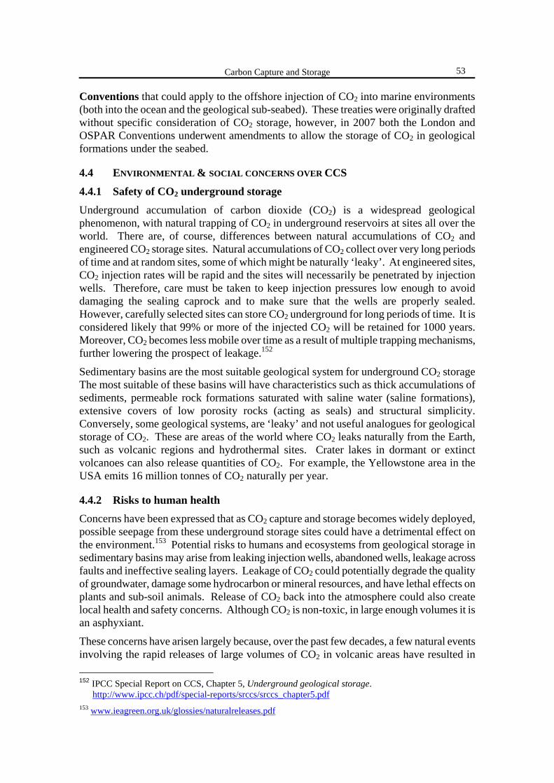
Carbon Capture and Storage
53
Conventions that could apply to the offshore injection of CO2 into marine environments (both into the ocean and the geological sub-seabed). These treaties were originally drafted without specific consideration of CO2 storage, however, in 2007 both the London and OSPAR Conventions underwent amendments to allow the storage of CO2 in geological formations under the seabed.
4.4 ENVIRONMENTAL & SOCIAL CONCERNS OVER CCS
4.4.1 Safety of CO2 underground storage
Underground accumulation of carbon dioxide (CO2) is a widespread geological phenomenon, with natural trapping of CO2 in underground reservoirs at sites all over the world. There are, of course, differences between natural accumulations of CO2 and engineered CO2 storage sites. Natural accumulations of CO2 collect over very long periods of time and at random sites, some of which might be naturally ‘leaky’. At engineered sites, CO2 injection rates will be rapid and the sites will necessarily be penetrated by injection wells. Therefore, care must be taken to keep injection pressures low enough to avoid damaging the sealing caprock and to make sure that the wells are properly sealed. However, carefully selected sites can store CO2 underground for long periods of time. It is considered likely that 99% or more of the injected CO2 will be retained for 1000 years. Moreover, CO2 becomes less mobile over time as a result of multiple trapping mechanisms, further lowering the prospect of leakage.152
Sedimentary basins are the most suitable geological system for underground CO2 storage The most suitable of these basins will have characteristics such as thick accumulations of sediments, permeable rock formations saturated with saline water (saline formations), extensive covers of low porosity rocks (acting as seals) and structural simplicity. Conversely, some geological systems, are ‘leaky’ and not useful analogues for geological storage of CO2. These are areas of the world where CO2 leaks naturally from the Earth, such as volcanic regions and hydrothermal sites. Crater lakes in dormant or extinct volcanoes can also release quantities of CO2. For example, the Yellowstone area in the USA emits 16 million tonnes of CO2 naturally per year.
4.4.2 Risks to human health
Concerns have been expressed that as CO2 capture and storage becomes widely deployed, possible seepage from these underground storage sites could have a detrimental effect on the environment.153 Potential risks to humans and ecosystems from geological storage in sedimentary basins may arise from leaking injection wells, abandoned wells, leakage across faults and ineffective sealing layers. Leakage of CO2 could potentially degrade the quality of groundwater, damage some hydrocarbon or mineral resources, and have lethal effects on plants and sub-soil animals. Release of CO2 back into the atmosphere could also create local health and safety concerns. Although CO2 is non-toxic, in large enough volumes it is an asphyxiant.
These concerns have arisen largely because, over the past few decades, a few natural events involving the rapid releases of large volumes of CO2 in volcanic areas have resulted in 152 IPCC Special Report on CCS, Chapter 5, Underground geological storage.
http://www.ipcc.ch/pdf/special-reports/srccs/srccs_chapter5.pdf 153 www.ieagreen.org.uk/glossies/naturalreleases.pdf
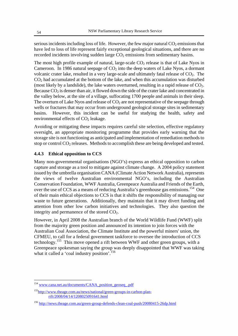
NSW Parliamentary Library Research Service
54
serious incidents including loss of life. However, the few major natural CO2 emissions that have led to loss of life represent fairly exceptional geological situations, and there are no recorded incidents involving sudden large CO2 emissions from sedimentary basins.
The most high profile example of natural, large-scale CO2 release is that of Lake Nyos in Cameroon. In 1986 natural seepage of CO2 into the deep waters of Lake Nyos, a dormant volcanic crater lake, resulted in a very large-scale and ultimately fatal release of CO2. The CO2 had accumulated at the bottom of the lake, and when this accumulation was disturbed (most likely by a landslide), the lake waters overturned, resulting in a rapid release of CO2. Because CO2 is denser than air, it flowed down the side of the crater lake and concentrated in the valley below, at the site of a village, suffocating 1700 people and animals in their sleep. The overturn of Lake Nyos and release of CO2 are not representative of the seepage through wells or fractures that may occur from underground geological storage sites in sedimentary basins. However, this incident can be useful for studying the health, safety and environmental effects of CO2 leakage.
Avoiding or mitigating these impacts requires careful site selection, effective regulatory oversight, an appropriate monitoring programme that provides early warning that the storage site is not functioning as anticipated and implementation of remediation methods to stop or control CO2 releases. Methods to accomplish these are being developed and tested.
4.4.3 Ethical opposition to CCS
Many non-governmental organisations (NGO’s) express an ethical opposition to carbon capture and storage as a tool to mitigate against climate change. A 2004 policy statement issued by the umbrella organisation CANA (Climate Action Network Australia), represents the views of twelve Australian environmental NGO’s, including the Australian Conservation Foundation, WWF Australia, Greenpeace Australia and Friends of the Earth, over the use of CCS as a means of reducing Australia’s greenhouse gas emissions.154 One of their main ethical objections to CCS is that it shifts the responsibility of managing our waste to future generations. Additionally, they maintain that it may divert funding and attention from other low carbon initiatives and technologies. They also question the integrity and permanence of the stored CO2.
However, in April 2008 the Australian branch of the World Wildlife Fund (WWF) split from the majority green position and announced its intention to join forces with the Australian Coal Association, the Climate Institute and the powerful miners' union, the CFMEU, to call for a federal government taskforce to oversee the introduction of CCS technology.155 This move opened a rift between WWF and other green groups, with a Greenpeace spokesman saying the group was deeply disappointed that WWF was taking what it called a ‘coal industry position’.156
154 www.cana.net.au/documents/CANA_position_geoseq_.pdf 155http://www.theage.com.au/news/national/green-groups-in-carbon-plan-
rift/2008/04/14/1208025091641.html 156 http://news.theage.com.au/green-group-defends-clean-coal-push/20080415-26dp.html

Carbon Capture and Storage
55
4.5 PUBLIC AWARENESS OF CCS
The main focus of research on carbon capture and storage (CCS) to date has been on the technical, economic and environmental aspects of this technology. Results of the very few studies conducted to date about the public perception of CCS indicate that the public is generally not well informed about CCS.157, 158, 159
Assessing public perception of CCS is challenging because of: a) the early stage of the technology, with very few examples and experiences in the
public domain to draw upon as illustrations; b) the relatively technical and ‘remote’ nature of the issue, meaning that there are few
immediate points of connection in the lay public’s frame of reference to many of the key concepts.
In 2003, researchers at the UK’s Tyndall Centre for Climate Change Research at the University of East Anglia, conducted a series of public surveys to determine public perception of carbon capture and storage (CCS).160 The potential public perceptions of CCS have been recognized as a vital aspect which may hinder (or possibly even facilitate) the future development of this technology.
When asked, unprompted, if they could think of any negative effects of CCS respondents’ most frequent answers were as follows:
• leakage (49%) • ecosystems (31%) • the new and untested nature of the technology (23%) • human health impacts (18%).
Although these practical, physical risks were the most frequently mentioned, there were also a number of negative attributes mentioned in relation to CCS as a part of climate change abatement policy:
• avoiding the real problem (13%), • short termism (12%), • the policy demonstrated reluctance to change by government (11%).
Grouping these last three responses into a general concern that CCS is treating the symptoms not the cause of excessive CO2 emissions, this would constitute, at 36%, the second most frequently mentioned negative aspect of CCS. Many respondents indicated that they would like more information and more certainty in the risk assessments of CCS 157 Public understanding of carbon sequestration in Australia, (2007), Miller, E., Bell, L. & Buys, L.,
Aust J. of Emerging Technologies & Society, 5 (1) http://www.swin.edu.au/sbs/ajets/journal/V5N1/V5N1abstract_milleretal.htm
158 Public Perception of Carbon Dioxide Capture and Storage: Prioritised Assessment of Issues and Concerns. Summary for Policy-Makers (2007). Commissioned by International Energy Agency Working Party on Fossil Fuels, and Funded by UK Department of Trade and Industry, http://www.co2captureproject.org/news/documents/2007Updates/IEA%20WPFF%20CCS%20COMMUNICATIONS%20STRATEGY-SPM%20-%2023%20March.pdf
159 The Public Perceptions of Carbon Capture and Storage, Shackley, S., McLachlan, C. & Gough, C., (2004), Tyndall Centre for Climate Change Research, Working Paper 44, http://www.tyndall.ac.uk/publications/working_papers/wp44.pdf
160 ibid.
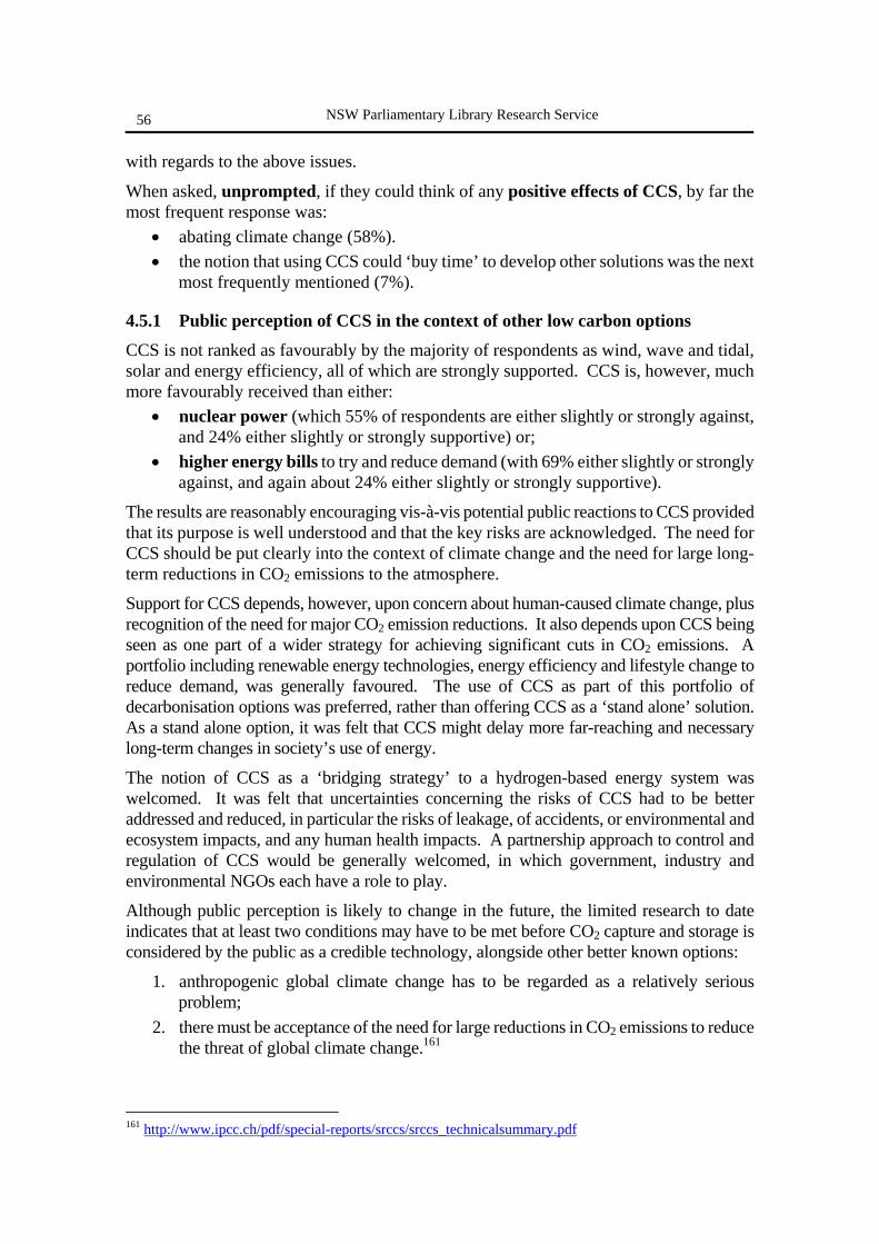
NSW Parliamentary Library Research Service
56
with regards to the above issues.
When asked, unprompted, if they could think of any positive effects of CCS, by far the most frequent response was:
• abating climate change (58%). • the notion that using CCS could ‘buy time’ to develop other solutions was the next
most frequently mentioned (7%).
4.5.1 Public perception of CCS in the context of other low carbon options
CCS is not ranked as favourably by the majority of respondents as wind, wave and tidal, solar and energy efficiency, all of which are strongly supported. CCS is, however, much more favourably received than either:
• nuclear power (which 55% of respondents are either slightly or strongly against, and 24% either slightly or strongly supportive) or;
• higher energy bills to try and reduce demand (with 69% either slightly or strongly against, and again about 24% either slightly or strongly supportive).
The results are reasonably encouraging vis-à-vis potential public reactions to CCS provided that its purpose is well understood and that the key risks are acknowledged. The need for CCS should be put clearly into the context of climate change and the need for large long-term reductions in CO2 emissions to the atmosphere.
Support for CCS depends, however, upon concern about human-caused climate change, plus recognition of the need for major CO2 emission reductions. It also depends upon CCS being seen as one part of a wider strategy for achieving significant cuts in CO2 emissions. A portfolio including renewable energy technologies, energy efficiency and lifestyle change to reduce demand, was generally favoured. The use of CCS as part of this portfolio of decarbonisation options was preferred, rather than offering CCS as a ‘stand alone’ solution. As a stand alone option, it was felt that CCS might delay more far-reaching and necessary long-term changes in society’s use of energy.
The notion of CCS as a ‘bridging strategy’ to a hydrogen-based energy system was welcomed. It was felt that uncertainties concerning the risks of CCS had to be better addressed and reduced, in particular the risks of leakage, of accidents, or environmental and ecosystem impacts, and any human health impacts. A partnership approach to control and regulation of CCS would be generally welcomed, in which government, industry and environmental NGOs each have a role to play.
Although public perception is likely to change in the future, the limited research to date indicates that at least two conditions may have to be met before CO2 capture and storage is considered by the public as a credible technology, alongside other better known options:
1. anthropogenic global climate change has to be regarded as a relatively serious problem;
2. there must be acceptance of the need for large reductions in CO2 emissions to reduce the threat of global climate change.161
161 http://www.ipcc.ch/pdf/special-reports/srccs/srccs_technicalsummary.pdf
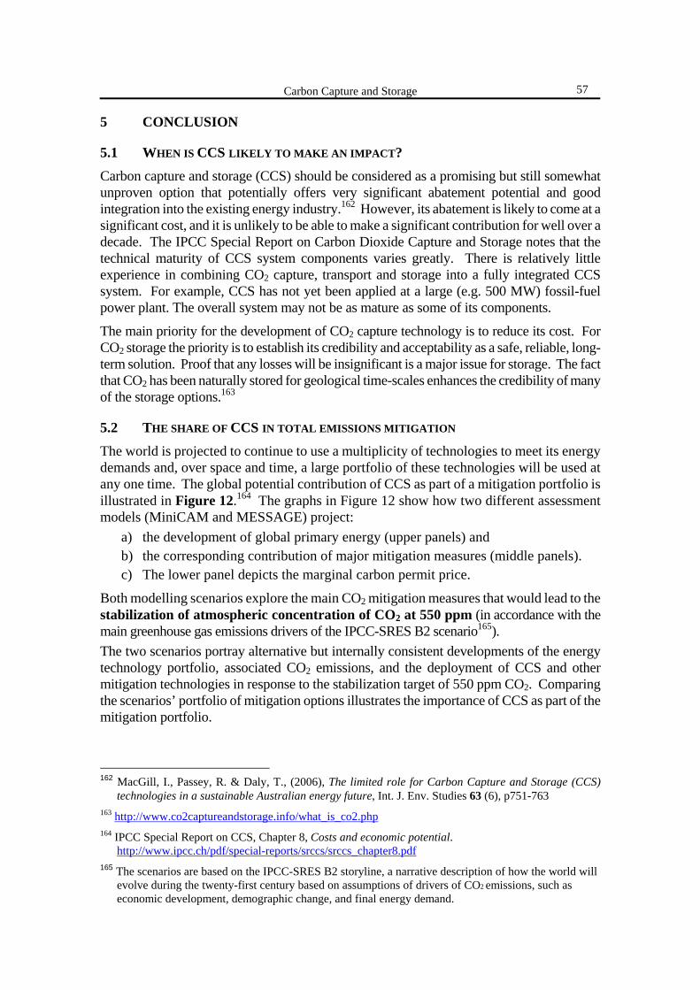
Carbon Capture and Storage
57
5 CONCLUSION
5.1 WHEN IS CCS LIKELY TO MAKE AN IMPACT?
Carbon capture and storage (CCS) should be considered as a promising but still somewhat unproven option that potentially offers very significant abatement potential and good integration into the existing energy industry.162 However, its abatement is likely to come at a significant cost, and it is unlikely to be able to make a significant contribution for well over a decade. The IPCC Special Report on Carbon Dioxide Capture and Storage notes that the technical maturity of CCS system components varies greatly. There is relatively little experience in combining CO2 capture, transport and storage into a fully integrated CCS system. For example, CCS has not yet been applied at a large (e.g. 500 MW) fossil-fuel power plant. The overall system may not be as mature as some of its components.
The main priority for the development of CO2 capture technology is to reduce its cost. For CO2 storage the priority is to establish its credibility and acceptability as a safe, reliable, long-term solution. Proof that any losses will be insignificant is a major issue for storage. The fact that CO2 has been naturally stored for geological time-scales enhances the credibility of many of the storage options.163
5.2 THE SHARE OF CCS IN TOTAL EMISSIONS MITIGATION
The world is projected to continue to use a multiplicity of technologies to meet its energy demands and, over space and time, a large portfolio of these technologies will be used at any one time. The global potential contribution of CCS as part of a mitigation portfolio is illustrated in Figure 12.164 The graphs in Figure 12 show how two different assessment models (MiniCAM and MESSAGE) project:
a) the development of global primary energy (upper panels) and b) the corresponding contribution of major mitigation measures (middle panels). c) The lower panel depicts the marginal carbon permit price.
Both modelling scenarios explore the main CO2 mitigation measures that would lead to the stabilization of atmospheric concentration of CO2 at 550 ppm (in accordance with the main greenhouse gas emissions drivers of the IPCC-SRES B2 scenario165). The two scenarios portray alternative but internally consistent developments of the energy technology portfolio, associated CO2 emissions, and the deployment of CCS and other mitigation technologies in response to the stabilization target of 550 ppm CO2. Comparing the scenarios’ portfolio of mitigation options illustrates the importance of CCS as part of the mitigation portfolio.
162 MacGill, I., Passey, R. & Daly, T., (2006), The limited role for Carbon Capture and Storage (CCS)
technologies in a sustainable Australian energy future, Int. J. Env. Studies 63 (6), p751-763 163 http://www.co2captureandstorage.info/what_is_co2.php 164 IPCC Special Report on CCS, Chapter 8, Costs and economic potential.
http://www.ipcc.ch/pdf/special-reports/srccs/srccs_chapter8.pdf 165 The scenarios are based on the IPCC-SRES B2 storyline, a narrative description of how the world will
evolve during the twenty-first century based on assumptions of drivers of CO2 emissions, such as economic development, demographic change, and final energy demand.
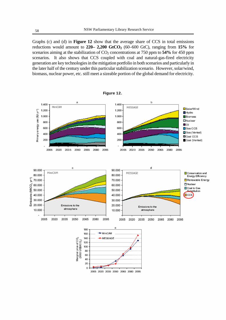
NSW Parliamentary Library Research Service
58
Graphs (c) and (d) in Figure 12 show that the average share of CCS in total emissions reductions would amount to 220– 2,200 GtCO2 (60–600 GtC), ranging from 15% for scenarios aiming at the stabilization of CO2 concentrations at 750 ppm to 54% for 450 ppm scenarios. It also shows that CCS coupled with coal and natural-gas-fired electricity generation are key technologies in the mitigation portfolio in both scenarios and particularly in the later half of the century under this particular stabilization scenario. However, solar/wind, biomass, nuclear power, etc. still meet a sizeable portion of the global demand for electricity.
Figure 12.
Carbon Capture and Storage
59
These technologies are modelled in such a way that they all compete for market share to provide the energy services and emissions reduction required by society, as this is what would happen in reality. In the light of this competition and the wide variety of possible emissions futures, the contribution of CCS to total emissions reduction can only be assessed within relatively wide margins.
Uncertainties in these economic potential estimates are significant. For CCS to achieve such an economic potential, several hundreds to thousands of CO2 capture systems would need to be installed over the coming century, each capturing some 1-5 MtCO2 per year. The actual implementation of CCS is likely to be lower than the economic potential due to factors such as environmental impacts, risks of leakage and the lack of a clear legal framework or public acceptance.
5.3 CCS IS NOT A ‘MAGIC BULLET’ SOLUTION
No single technology provides the solution to economically cutting carbon-dioxide emissions from fossil fuel combustion. There are many ways in which CO2 emissions can be reduced, such as improving energy efficiency and switching to renewable and low-carbon methods of electricity generation. However, most scenarios suggest that these steps alone will not achieve the required reductions in CO2 emissions. Carbon capture and storage (CCS) will therefore be only part of a suite of solutions. The advantage of CCS is that widespread use of this technique could be achieved without the need for rapid change in the energy supply infrastructure. In the long-term the world's energy system may have to be based on non-fossil energy sources. Decarbonising the use of fossil fuels, by capture and storage of CO2, may help the transition to a future carbon-free energy system.

Recent Research Service Publications To anticipate and fulfil the information needs of Members of Parliament and the Parliamentary Institution. [Library Mission Statement] Note: For a complete listing of all Research Service Publications
contact the Research Service on 9230 2093. The complete list is also on the Internet at:
http://www.parliament.nsw.gov.au/prod/web/PHWebContent.nsf/PHPages/LibraryPublist
BACKGROUND PAPERS 2004 NSW Redistribution: Analysis of Final Boundaries by Antony Green 1/05 Children’s Rights in NSW by Lenny Roth 2/05 NSW By-elections, 1965-2005 by Antony Green 3/05 The Science of Climate Change by Stewart Smith 1/06 NSW State Electoral Districts Ranked by 2001 Census Characteristics by Talina Drabsch 2/06 NSW Electorate Profiles: 2004 Redistribution by Talina Drabsch 3/06 Parliamentary Privilege: Major Developments and Current Issues by Gareth Griffith 1/07 2007 NSW Election: Preliminary Analysis by Antony Green 2/07 Manufacturing and Services in NSW by John Wilkinson 3/07 2007 NSW Election: Final Analysis by Antony Green 1/08 BRIEFING PAPERS Tobacco Control in NSW by Talina Drabsch 1/05 Energy Futures for NSW by Stewart Smith 2/05 Small Business in NSW by John Wilkinson 3/05 Trial by Jury: Recent Developments by Rowena Johns 4/05 Land Tax: an Update by Stewart Smith 5/05 No Fault Compensation by Talina Drabsch 6/05 Waste Management and Extended Producer Responsibility by Stewart Smith 7/05 Rural Assistance Schemes and Programs by John Wilkinson 8/05 Abortion and the law in New South Wales by Talina Drabsch 9/05 Desalination, Waste Water, and the Sydney Metropolitan Water Plan by Stewart Smith 10/05 Industrial Relations Reforms: the proposed national system by Lenny Roth 11/05 Parliament and Accountability: the role of parliamentary oversight committees by Gareth Griffith 12/05 Election Finance Law: an update by Talina Drabsch 13/05 Affordable Housing in NSW: past to present by John Wilkinson 14/05 Majority Jury Verdicts in Criminal Trials by Talina Drabsch 15/05 Sedition, Incitement and Vilification: issues in the current debate by Gareth Griffith 1/06 The New Federal Workplace Relations System by Lenny Roth 2/06 The Political Representation of Ethnic and Racial Minorities by Karina Anthony 3/06 Preparing for the Impact of Dementia by Talina Drabsch 4/06 A NSW Charter of Rights? The Continuing Debate by Gareth Griffith 5/06 Native Vegetation: an update by Stewart Smith 6/06 Parental Responsibility Laws by Lenny Roth 7/06 Tourism in NSW: Prospects for the Current Decade by John Wilkinson 8/06 Legal Recognition of Same Sex Relationships by Karina Anthony and Talina Drabsch 9/06 Uranium and Nuclear Power by Stewart Smith 10/06 DNA Evidence, Wrongful Convictions and Wrongful Acquittals by Gareth Griffith and Lenny Roth 11/06 Law and Order Legislation in the Australian States and Territories: 2003-2006 by Lenny Roth 12/06 Biofuels by Stewart Smith 13/06 Sovereign States and National Power: Transition in Federal- State Finance by John Wilkinson 14/06 Reducing the Risk of Recidivism by Talina Drabsch 15/06

Recent Developments in Planning Legislation by Stewart Smith 16/06 Commonwealth-State Responsibilities for Health – ‘Big Bang’ or Incremental Reform? by Gareth Griffith 17/06 The Workplace Relations Case – Implications for the States by Lenny Roth and Gareth Griffith 18/06 Crystal Methamphetamine Use in NSW by Talina Drabsch 19/06 Government Policy and Services to Support and Include People with Disabilities by Lenny Roth 1/07 Greenhouse Gas Emission Trading by Stewart Smith 2/07 Provocation and Self-defence in Intimate Partner and Homophobic Homicides by Lenny Roth 3/07 Living on the Edge: Sustainable Land Development in Sydney by Jackie Ohlin 4/07 Women, Parliament and the Media by Talina Drabsch 5/07 Freedom of Information: Issues and Recent Developments in NSW by Gareth Griffith 6/07 Domestic Violence in NSW by Talina Drabsch 7/07 Election Finance Law: Recent Developments and Proposals for Reform by Gareth Griffith and Talina Drabsch 8/07 Multiculturalism by Lenny Roth 9/07 Protecting Children From Online Sexual Predators by Gareth Griffith and Lenny Roth 10/07 Older Drivers: A Review of Licensing Requirements and Research Findings by Gareth Griffith 11/07 Liquor Licensing Laws: An Update by Lenny Roth 12/07 Residential Tenancy Law in NSW by Gareth Griffith and Lenny Roth 13/07 The NSW Economy: A Survey by John Wilkinson 14/07 The Planning System: Proposed Reforms by Stewart Smith 1/08 Carbon Capture and Storage by Stephanie Baldwin 2/08