Brief Operating Instructions - Lauda-Brinkmann + K_KP.pdf · Operating Instructions LAUDA Compact...
87
Operating Instructions LAUDA Compact Thermostats C 6 CP, C 12 CP, C 20 CP K 6 KP, K 12 KP, K 20 KP LAUDA Clear-View Thermostats D 15 KP, D 20 KP, D 30 KP DL 15 KP, DL 20 KP LAUDA DR. R. WOBSER GMBH & CO. KG P.O. Box 1251 97912 Lauda-Königshofen from Series Z 01 Tel: (+49) (0) 9343/ 503-0 00/01 Fax: (+49) (0) 9343/ 503-222 Software version 2.16 E-mail info @ lauda.de YACE0051 Internet http://www.lauda.de
Transcript of Brief Operating Instructions - Lauda-Brinkmann + K_KP.pdf · Operating Instructions LAUDA Compact...
Operating Instructions
LAUDA Compact ThermostatsC 6 CP, C 12 CP, C 20 CPK 6 KP, K 12 KP, K 20 KP
LAUDA Clear-View ThermostatsD 15 KP, D 20 KP, D 30 KP
DL 15 KP, DL 20 KP
LAUDA DR. R. WOBSERGMBH & CO. KGP.O. Box 125197912 Lauda-Königshofen
from Series Z 01 Tel: (+49) (0) 9343/ 503-000/01 Fax: (+49) (0) 9343/ 503-222Software version 2.16 E-mail info @ lauda.deYACE0051 Internet http://www.lauda.de

LAUDA Compact ThermostatsC 6 CP, C 12 CP, C 20 CP, K 6 KP, K 12 KP, K 20 KPD 15 KP, D 20 KP, D 30 KP, DL 15 KP, DL 20 KP
YACE0051 / 27.03.2001 - 3 -
1 BRIEF OPERATING INSTRUCTIONS ..................................................................................... 61.1 Fitting the tubing to the pump connections:...................................................................................6
1.2 Operating safety .................................................................................................................................7
1.3 Warning ...............................................................................................................................................7
2 TECHNICAL DATA TO DIN 58966 .......................................................................................... 8
3 GENERAL CONSTRUCTION AND TECHNICAL DESCRIPTION.......................................... 153.1 Operating principle ..........................................................................................................................15
3.1.1 Bath/Circulation Thermostats......................................................................................................153.1.2 Clear-View Thermostats .............................................................................................................15
3.2 Materials............................................................................................................................................16
3.3 Cooling coil.......................................................................................................................................16
3.4 Pumps ...............................................................................................................................................16
3.5 Temperature control and electronics.............................................................................................17
3.6 Mains supply output 34 H................................................................................................................18
3.7 Controlled cooling............................................................................................................................18
3.8 Remote operation (FBC) (option) ...................................................................................................18
4 SAFETY DEVICES AND WARNING NOTES......................................................................... 184.1 Safety functions ...............................................................................................................................18
4.2 Why can a thermostat be dangerous? ...........................................................................................19
4.3 Important notes ................................................................................................................................20
4.4 Warning notes ..................................................................................................................................204.4.1 Temperatures..............................................................................................................................204.4.2 Mains connection ........................................................................................................................204.4.3 Mains cable .................................................................................................................................204.4.4 Fume extraction ..........................................................................................................................214.4.5 Cooling water, steam production.................................................................................................21
5 BATH LIQUIDS AND HOSE CONNECTIONS ....................................................................... 215.1 Bath liquids.......................................................................................................................................21
5.2 Hose connections ............................................................................................................................235.2.1 Perbunan tubing..........................................................................................................................235.2.2 Silicone tubing.............................................................................................................................235.2.3 Metal hoses.................................................................................................................................24
6 UNPACKING, ASSEMBLY AND SETTING UP...................................................................... 246.1 Unpacking .........................................................................................................................................24
6.2 Setting up, operation as bath thermostat ......................................................................................25
7 CONNECTION OF EXTERNAL SYSTEMS............................................................................ 257.1 Closed external circuits...................................................................................................................25
LAUDA Compact ThermostatsC 6 CP, C 12 CP, C 20 CP, K 6 KP, K 12 KP, K 20 KP,D 15 KP, D 20 KP, D 30 KP, DL 15 KP, DL 20 KP
YACE0051 / 27.03.2001 - 4 -
7.2 Open systems (baths)......................................................................................................................267.2.1 Fitting the level controller ............................................................................................................26
8 COOLING THE THERMOSTATS........................................................................................... 278.1 Mains water cooling.........................................................................................................................28
8.2 Through-flow chillers DLK 10, DLK 25 and DLK 45......................................................................28
9 STARTING UP ....................................................................................................................... 289.1 Filling.................................................................................................................................................28
9.2 Connection to supply.......................................................................................................................28
9.3 Basic functions.................................................................................................................................299.3.1 Supply switch-on .........................................................................................................................299.3.2 Standard display..........................................................................................................................299.3.3 Basic action on inputs and outputs .............................................................................................309.3.4 Overtemperature switch-off point................................................................................................309.3.5 Low temperature switch-off point ................................................................................................329.3.6 Setpoint input ..............................................................................................................................32
9.4 Parameter level PAR ........................................................................................................................329.4.1 Auto-adaptation...........................................................................................................................329.4.2 Output limitation ..........................................................................................................................339.4.3 Display resolution L1...................................................................................................................349.4.4 Contact input Fault 14 N .............................................................................................................349.4.5 Baud rate RS 232........................................................................................................................359.4.6 Menu language ...........................................................................................................................359.4.7 Calibrating the analogue output channels...................................................................................359.4.8 Operation with through-flow chiller DLK 45 with proportional cooling .........................................36
9.5 Calibration of the temperature measurement circuits..................................................................36
9.6 Control parameters ..........................................................................................................................379.6.1 Indication and input of the control parameters............................................................................379.6.2 Recommendations for the control parameters............................................................................389.6.3 Bath temperature limitation .........................................................................................................389.6.4 Correction limitation ....................................................................................................................39
9.7 External control ................................................................................................................................409.7.1 External measurement inputs and external controller.................................................................409.7.2 Start of external control ...............................................................................................................419.7.3 Notes...........................................................................................................................................41
9.8 Working with controlled cooling ....................................................................................................42
9.9 Operation with programmer............................................................................................................449.9.1 Programme input ........................................................................................................................449.9.2 Example of a programme ...........................................................................................................469.9.3 Programme test ..........................................................................................................................479.9.4 Changing the programme data ...................................................................................................479.9.5 Programme start, interruption and abort .....................................................................................47
9.10 Connection for analogue signals socket 52 S...............................................................................48
9.11 Analogue inputs ...............................................................................................................................49
9.12 Analogue outputs.............................................................................................................................529.12.1 Temperature signal channel 1 ....................................................................................................529.12.2 Temperature signal channel 2 ....................................................................................................54
9.13 Safety function .................................................................................................................................54
LAUDA Compact ThermostatsC 6 CP, C 12 CP, C 20 CP, K 6 KP, K 12 KP, K 20 KPD 15 KP, D 20 KP, D 30 KP, DL 15 KP, DL 20 KP
YACE0051 / 27.03.2001 - 5 -
9.13.1 Low-level cut-out .........................................................................................................................549.13.2 Adjustable overtemperature limiter .............................................................................................549.13.3 Connection potential-free contact "Combined fault" 12 N (Alarm off) .........................................56
9.14 Serial interface RS 232 C .................................................................................................................569.14.1 Data of the RS 232 C interface ...................................................................................................569.14.2 General principles .......................................................................................................................579.14.3 Output commands.......................................................................................................................589.14.4 Requesting data from the thermostat..........................................................................................609.14.5 Error messages on the computer ...............................................................................................61
9.15 Timing clock function ......................................................................................................................629.15.1 Setting and indication of date and time.......................................................................................629.15.2 Timing clock function ..................................................................................................................639.15.3 Activating the timing clock function .............................................................................................63
10 MAINTENANCE ..................................................................................................................... 6410.1 Safety notes in case of repairs .......................................................................................................64
10.2 Repair and re-initilisation ................................................................................................................64
10.3 Cleaning ............................................................................................................................................65
10.4 Spares ordering................................................................................................................................65
11 ACCESSORIES ..................................................................................................................... 66

LAUDA Compact ThermostatsC 6 CP, C 12 CP, C 20 CP, K 6 KP, K 12 KP, K 20 KP,D 15 KP, D 20 KP, D 30 KP, DL 15 KP, DL 20 KP
YACE0051 / 27.03.2001 - 6 -
1 Brief Operating Instructions
Even if you find these brief instructions initially sufficient please read the followingsections, especially Section 4: "Safety devices and warning notes".For safe operation of the equipment it is essential that the information in theseOperating Instructions is observed.
Check the thermostat and the accessories during unpacking for any transport damageand if necessary inform the carrier or the postal authority.
Assemble the unit according to Section 6 and add extra items as appropriate.
1.1 Fitting the tubing to the pump connections:
Without external system: for improved circulation within the bath remove the closingplugs from both of the pump connections, fit the tubing nipples and link them togetherwith e.g. Perbunan tubing (up to 120°C) or better a metal tubing.
For clear-view thermostats: for improved circulation within the bath close the pumpconnections with the closing plugs (see "Standard accessories", Item 6.1).
With external system: make tubing connections to the external system.
Protect the tubing with hose clips against slipping off.
When working near the ambient temperature connect up the external cooling accordingto Section 8.
Use only softened water or LAUDA bath liquids (Section 5). Fill up the bath to a levelabout 2 cm below the cover plate.
Check the supply voltage against the details on the label. Insert the mains plug.
Switch on the supply switch (green lamp lights up)
The display shows the software version and the type of unit, followed by the standarddisplay.
LAUDA Compact ThermostatsC 6 CP, C 12 CP, C 20 CP, K 6 KP, K 12 KP, K 20 KPD 15 KP, D 20 KP, D 30 KP, DL 15 KP, DL 20 KP
YACE0051 / 27.03.2001 - 7 -
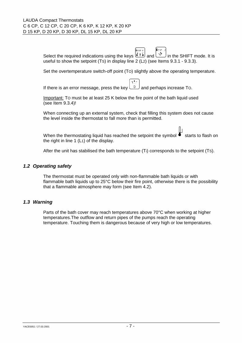
Select the required indications using the keys and in the SHIFT mode. It isuseful to show the setpoint (TS) in display line 2 (L2) (see Items 9.3.1 - 9.3.3).
Set the overtemperature switch-off point (TO) slightly above the operating temperature.
If there is an error message, press the key and perhaps increase TO.
Important: TO must be at least 25 K below the fire point of the bath liquid used(see Item 9.3.4)!
When connecting up an external system, check that filling this system does not causethe level inside the thermostat to fall more than is permitted.
When the thermostating liquid has reached the setpoint the symbol starts to flash onthe right in line 1 (L1) of the display.
After the unit has stabilised the bath temperature (Ti) corresponds to the setpoint (TS).
1.2 Operating safety
The thermostat must be operated only with non-flammable bath liquids or withflammable bath liquids up to 25°C below their fire point, otherwise there is the possibilitythat a flammable atmosphere may form (see Item 4.2).
1.3 Warning
Parts of the bath cover may reach temperatures above 70°C when working at highertemperatures.The outflow and return pipes of the pumps reach the operatingtemperature. Touching them is dangerous because of very high or low temperatures.
LAUDA Compact ThermostatsC 6 CP, C 12 CP, C 20 CP, K 6 KP, K 12 KP, K 20 KP,D 15 KP, D 20 KP, D 30 KP, DL 15 KP, DL 20 KP
YACE0051 / 27.03.2001 - 8 -
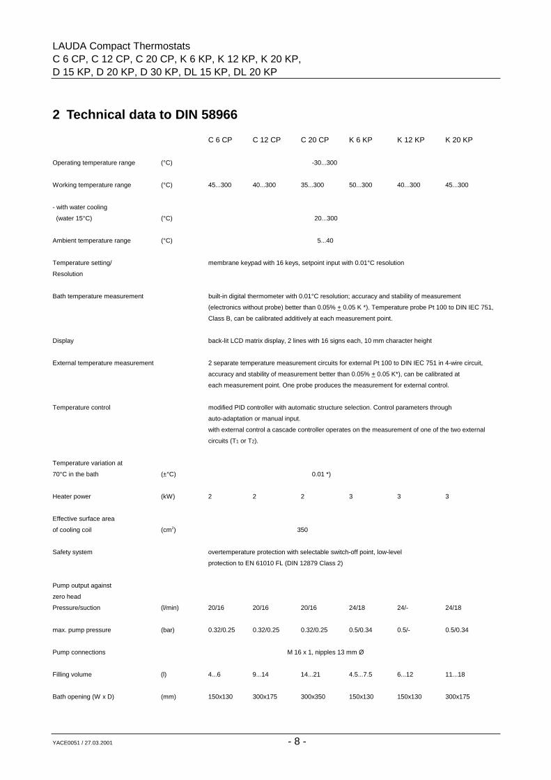
2 Technical data to DIN 58966
C 6 CP C 12 CP C 20 CP K 6 KP K 12 KP K 20 KP
Operating temperature range (°C) -30...300
Working temperature range (°C) 45...300 40...300 35...300 50...300 40...300 45...300
- with water cooling
(water 15°C) (°C) 20...300
Ambient temperature range (°C) 5...40
Temperature setting/ membrane keypad with 16 keys, setpoint input with 0.01°C resolution
Resolution
Bath temperature measurement built-in digital thermometer with 0.01°C resolution; accuracy and stability of measurement
(electronics without probe) better than 0.05% + 0.05 K *). Temperature probe Pt 100 to DIN IEC 751,
Class B, can be calibrated additively at each measurement point.
Display back-lit LCD matrix display, 2 lines with 16 signs each, 10 mm character height
External temperature measurement 2 separate temperature measurement circuits for external Pt 100 to DIN IEC 751 in 4-wire circuit,
accuracy and stability of measurement better than 0.05% + 0.05 K*), can be calibrated at
each measurement point. One probe produces the measurement for external control.
Temperature control modified PID controller with automatic structure selection. Control parameters through
auto-adaptation or manual input.
with external control a cascade controller operates on the measurement of one of the two external
circuits (T1 or T2).
Temperature variation at
70°C in the bath (±°C) 0.01 *)
Heater power (kW) 2 2 2 3 3 3
Effective surface area
of cooling coil (cm2) 350
Safety system overtemperature protection with selectable switch-off point, low-level
protection to EN 61010 FL (DIN 12879 Class 2)
Pump output against
zero head
Pressure/suction (l/min) 20/16 20/16 20/16 24/18 24/- 24/18
max. pump pressure (bar) 0.32/0.25 0.32/0.25 0.32/0.25 0.5/0.34 0.5/- 0.5/0.34
Pump connections M 16 x 1, nipples 13 mm Ø
Filling volume (l) 4...6 9...14 14...21 4.5...7.5 6...12 11...18
Bath opening (W x D) (mm) 150x130 300x175 300x350 150x130 150x130 300x175
LAUDA Compact ThermostatsC 6 CP, C 12 CP, C 20 CP, K 6 KP, K 12 KP, K 20 KPD 15 KP, D 20 KP, D 30 KP, DL 15 KP, DL 20 KP
YACE0051 / 27.03.2001 - 9 -
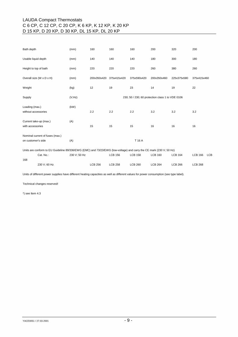
Bath depth (mm) 160 160 160 200 320 200
Usable liquid depth (mm) 140 140 140 180 300 180
Height to top of bath (mm) 220 220 220 260 380 260
Overall size (W x D x H) (mm) 200x350x420 375x415x420 375x590x420 200x350x460 225x375x580 375x415x460
Weight (kg) 12 19 23 14 19 22
Supply (V;Hz) 230; 50 / 230; 60 protection class 1 to VDE 0106
Loading (max.) (kW)
without accessories 2.2 2.2 2.2 3.2 3.2 3.2
Current take-up (max.) (A)
with accessories 15 15 15 16 16 16
Nominal current of fuses (max.)
on customer's side (A) T 16 A
Units are conform to EU Guideline 89/336/EWG (EMC) and 73/23/EWG (low-voltage) and carry the CE mark (230 V; 50 Hz)
Cat. No.: 230 V; 50 Hz LCB 156 LCB 158 LCB 160 LCB 164 LCB 166 LCB
168
230 V; 60 Hz LCB 256 LCB 258 LCB 260 LCB 264 LCB 266 LCB 268
Units of different power supplies have different heating capacities as well as different values for power consumption (see type label).
Technical changes reserved!
*) see Item 4.3
LAUDA Compact ThermostatsC 6 CP, C 12 CP, C 20 CP, K 6 KP, K 12 KP, K 20 KP,D 15 KP, D 20 KP, D 30 KP, DL 15 KP, DL 20 KP
YACE0051 / 25.06.2001 - 10 -
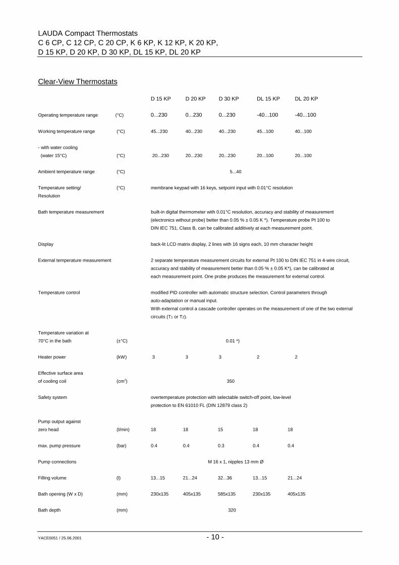
Clear-View Thermostats
D 15 KP D 20 KP D 30 KP DL 15 KP DL 20 KP
Operating temperature range (°C) 0...230 0...230 0...230 -40...100 -40...100
Working temperature range (°C) 45...230 40...230 40...230 45...100 40...100
- with water cooling
(water 15°C) (°C) 20...230 20...230 20...230 20...100 20...100
Ambient temperature range (°C) 5...40
Temperature setting/ (°C) membrane keypad with 16 keys, setpoint input with 0.01°C resolution
Resolution
Bath temperature measurement built-in digital thermometer with 0.01°C resolution, accuracy and stability of measurement
(electronics without probe) better than 0.05 % ± 0.05 K *). Temperature probe Pt 100 to
DIN IEC 751, Class B, can be calibrated additively at each measurement point.
Display back-lit LCD matrix display, 2 lines with 16 signs each, 10 mm character height
External temperature measurement 2 separate temperature measurement circuits for external Pt 100 to DIN IEC 751 in 4-wire circuit,
accuracy and stability of measurement better than 0.05 % ± 0.05 K*), can be calibrated at
each measurement point. One probe produces the measurement for external control.
Temperature control modified PID controller with automatic structure selection. Control parameters through
auto-adaptation or manual input.
With external control a cascade controller operates on the measurement of one of the two external
circuits (T1 or T2).
Temperature variation at
70°C in the bath (±°C) 0.01 *)
Heater power (kW) 3 3 3 2 2
Effective surface area
of cooling coil (cm2) 350
Safety system overtemperature protection with selectable switch-off point, low-level
protection to EN 61010 FL (DIN 12879 class 2)
Pump output against
zero head (l/min) 18 18 15 18 18
max. pump pressure (bar) 0.4 0.4 0.3 0.4 0.4
Pump connections M 16 x 1, nipples 13 mm Ø
Filling volume (l) 13...15 21...24 32...36 13...15 21...24
Bath opening (W x D) (mm) 230x135 405x135 585x135 230x135 405x135
Bath depth (mm) 320
LAUDA Compact ThermostatsC 6 CP, C 12 CP, C 20 CP, K 6 KP, K 12 KP, K 20 KPD 15 KP, D 20 KP, D 30 KP, DL 15 KP, DL 20 KP
YACE0051 / 27.03.2001 - 11 -
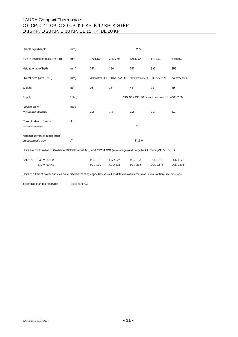
Usable liquid depth (mm) 265
Size of inspection glass (W x D) (mm) 170x250 345x250 525x250 170x250 345x250
Height to top of bath (mm) 390 390 390 395 395
Overall size (W x D x H) (mm) 480x235x590 710x235x590 1010x235x590 506x250x595 740x250x595
Weight (kg) 26 36 44 28 39
Supply (V;Hz) 230; 50 / 230; 60 protection class 1 to VDE 0106
Loading (max.) (kW)
without accessories 3.2 3.2 3.2 2.2 2.2
Current take-up (max.) (A)
with accessories 16
Nominal current of fuses (max.)
on customer's side (A) T 16 A
Units are conform to EU Guideline 89/336/EWG (EMC) and 73/23/EWG (low-voltage) and carry the CE mark (230 V; 50 Hz)
Cat. No. 230 V; 50 Hz LCD 121 LCD 122 LCD 123 LCD 1272 LCD 1273
230 V; 60 Hz LCD 221 LCD 222 LCD 223 LCD 2272 LCD 2273
Units of different power supplies have different heating capacities as well as different values for power consumption (see type label).
Technical changes reserved! *) see Item 4.3
LAUDA Compact ThermostatsC 6 CP, C 12 CP, C 20 CP, K 6 KP, K 12 KP, K 20 KP,D 15 KP, D 20 KP, D 30 KP, DL 15 KP, DL 20 KP
YACE0051 / 27.03.2001 - 12 -
LAUDA Compact ThermostatsC 6 CP, C 12 CP, C 20 CP, K 6 KP, K 12 KP, K 20 KPD 15 KP, D 20 KP, D 30 KP, DL 15 KP, DL 20 KP
YACE0051 / 27.03.2001 - 13 -
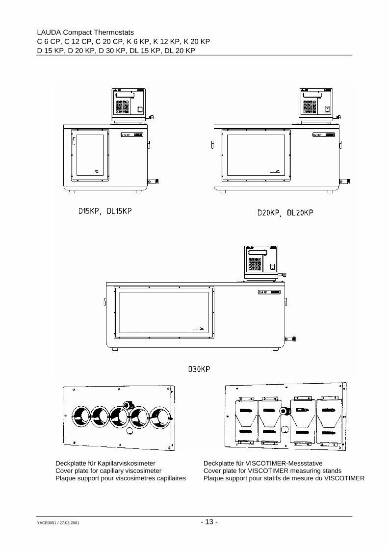
Deckplatte für KapillarviskosimeterCover plate for capillary viscosimeterPlaque support pour viscosimetres capillaires
Deckplatte für VISCOTIMER-MessstativeCover plate for VISCOTIMER measuring standsPlaque support pour statifs de mesure du VISCOTIMER
LAUDA Compact ThermostatsC 6 CP, C 12 CP, C 20 CP, K 6 KP, K 12 KP, K 20 KP,D 15 KP, D 20 KP, D 30 KP, DL 15 KP, DL 20 KP
YACE0051 / 07.01.2002 - 14 -
LAUDA Compact ThermostatsC 6 CP, C 12 CP, C 20 CP, K 6 KP, K 12 KP, K 20 KPD 15 KP, D 20 KP, D 30 KP, DL 15 KP, DL 20 KP
YACE0051 / 27.03.2001 - 15 -
3 General construction and technical description
3.1 Operating principle
3.1.1 Bath/Circulation Thermostats
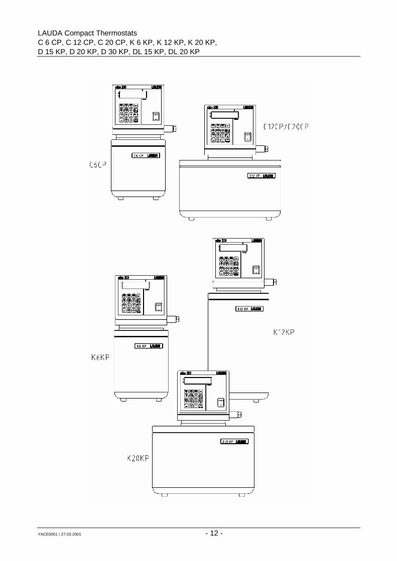
The LAUDA bath/circulation thermostats Series C and K with Electronics P differ in bathvolume, bath depth, pump type and output as well as in heating capacity. All types offeran operating temperature range of -30...300°C. Laboratory thermostats operate withliquids (operating medium, heat transfer fluid) which serve for energy transfer to theproduct to be thermostated.
The thermostated products can be immersed in the thermostatic bath (bath thermostat),or placed in an external open bath whose liquid is circulated by the pump of thethermostat.
When operating as circulator the thermostatic liquid is pumped through an external heatexchanger arranged by the user in which a product is being thermostated (jacketedvessels, reactors, heat exchangers).
3.1.2 Clear-View Thermostats
The LAUDA clear-view thermostats Series D and DL with Electronics P differ in bathvolume and temperature range. The units D...KP are equipped with double-walledinspection glasses and offer an operating temperature range of 0...230°C. The unitsDL...KP are equipped with four-fold insulating glasses for working in an operatingtemperature range of -40...100°C.The units are especially suitable for thermostating capillary viscometers.
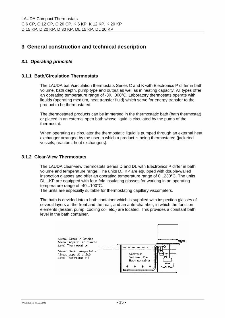
The bath is devided into a bath container which is supplied with inspection glasses ofseveral layers at the front and the rear, and an ante-chamber, in which the functionelements (heater, pump, cooling coil etc.) are located. This provides a constant bathlevel in the bath container.
LAUDA Compact ThermostatsC 6 CP, C 12 CP, C 20 CP, K 6 KP, K 12 KP, K 20 KP,D 15 KP, D 20 KP, D 30 KP, DL 15 KP, DL 20 KP
YACE0051 / 27.03.2001 - 16 -
3.2 Materials
All materials in contact with the bath liquid are made from rust-free stainless steel ormaterials of similar anti-corrosion properties.
3.3 Cooling coil
All units are fitted with a cooling coil which permits cooling, e.g. with water, for workingtemperatures in the range of the ambient temperature (see Item 4.4.5 and Section 8).
3.4 Pumps
All units except Type K 12 KP and the clear-view thermostats are equipped with acentrifugal pressure/suction pump. This can be used to operate both external openbaths as well as closed external systems (reactors).
The immersion pumps are supplied in the two performance classes C and K.
The thermostat K 12 KP is fitted with a pure pressure pump since this unit operatesspecially in the high temperature range with closed external systems.
The pressure pumps of the clear-view thermostats ensure an excellent circulation usingjet pipes and can also be used for external circulation if necessary.
The pumps are driven by external-runner motors with a continuous shaft.
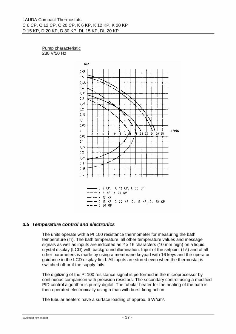
The pumps operate perfectly up to a viscosity of approx. 70 mm2/sec. (K 12 KP approx.120 mm2/sec.), with the pump output decreasing rapidly with increasing viscosity.
LAUDA Compact ThermostatsC 6 CP, C 12 CP, C 20 CP, K 6 KP, K 12 KP, K 20 KPD 15 KP, D 20 KP, D 30 KP, DL 15 KP, DL 20 KP
YACE0051 / 27.03.2001 - 17 -
Pump characteristic230 V/50 Hz
3.5 Temperature control and electronics
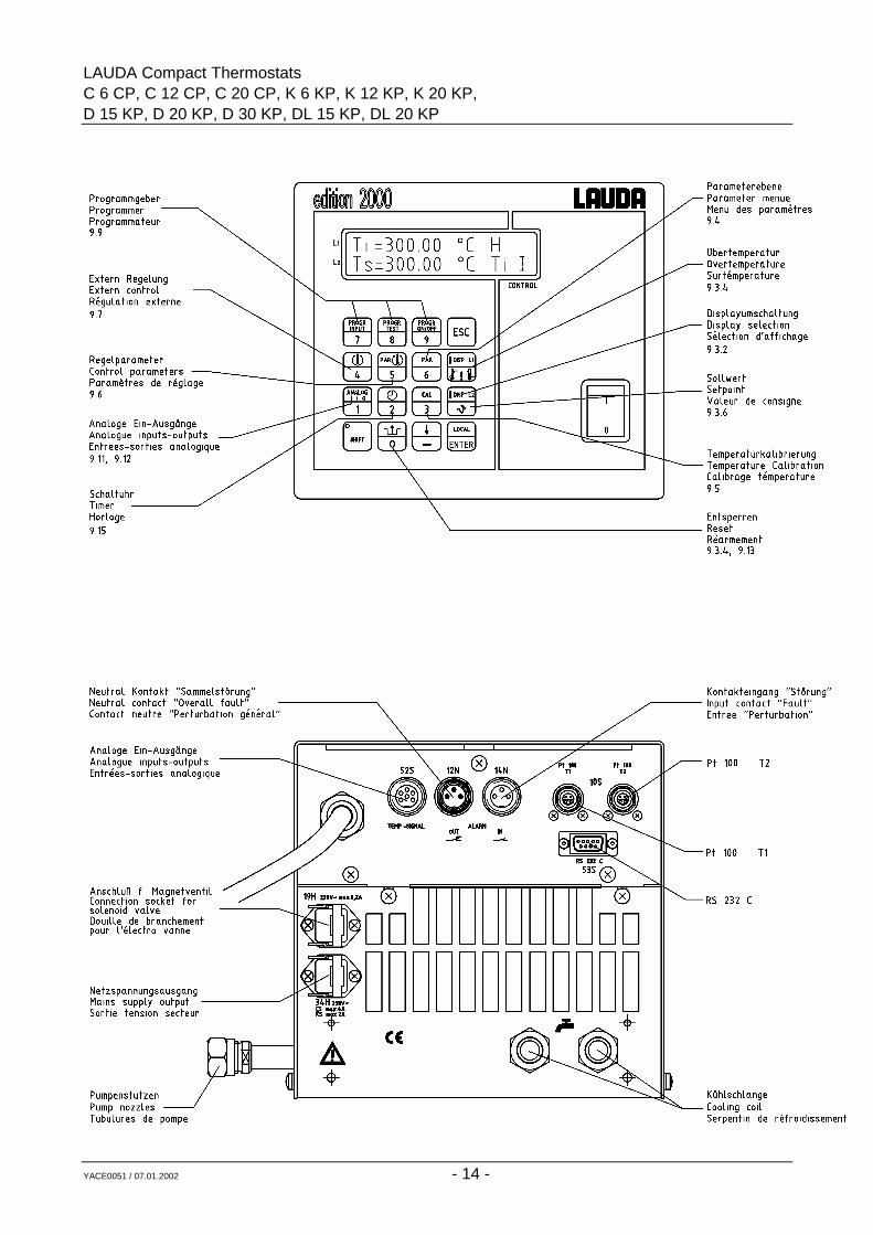
The units operate with a Pt 100 resistance thermometer for measuring the bathtemperature (Ti). The bath temperature, all other temperature values and messagesignals as well as inputs are indicated as 2 x 16 characters (10 mm high) on a liquidcrystal display (LCD) with background illumination. Input of the setpoint (TS) and of allother parameters is made by using a membrane keypad with 16 keys and the operatorguidance in the LCD display field. All inputs are stored even when the thermostat isswitched off or if the supply fails.
The digitizing of the Pt 100 resistance signal is performed in the microprocessor bycontinuous comparison with precision resistors. The secondary control using a modifiedPID control algorithm is purely digital. The tubular heater for the heating of the bath isthen operated electronically using a triac with burst firing action.
The tubular heaters have a surface loading of approx. 6 W/cm2.
LAUDA Compact ThermostatsC 6 CP, C 12 CP, C 20 CP, K 6 KP, K 12 KP, K 20 KP,D 15 KP, D 20 KP, D 30 KP, DL 15 KP, DL 20 KP
YACE0051 / 27.03.2001 - 18 -
3.6 Mains supply output 34 H
The 230 V supply voltage is available at the socket 34 H at the back in normal operationand with the unit switched on. The maximum current which can be drawn there is 4 A onC-P units and 2 A on K-P units. In case of a fault this supply is switched off. This outputcan be used e.g. to connect a through-flow chiller or a non-return fitting (Cat. No. UD125).
Suitable mating plug Cat. No. EQS 045
3.7 Controlled cooling
The units are equipped for controlled cooling to operate a solenoid valve which controlsthe cooling water flow.
This provides fully automatic cooling (20...100°C). It ensures faster heating up(compared to continuous cooling), greatly reduced water consumption and improvedtemperature control during heat dissipation since the heater does not operate againstthe cooling action.
Solenoid valve for cooling water control Cat. No. UD 085
3.8 Remote operation (FBC) (option)
As an option the units can be converted to remote control; then the entire electronicswith control panel is removed from the unit and used for remote operation. An adapterfor the cable connections is required on the basic unit and the control panel is placed inan extra housing. The conversion is to be carried out by a qualified electrician only. Allnecessary components except the connection cables are supplied as part of the kit.
Please specify the length of the connection cables. See accessories in the appendix.
4 Safety devices and warning notes
4.1 Safety functions
The built-in overtemperature limiter can be set over the complete operating temperaturerange.
The bath temperature is measured by a separate Pt 100 resistance sensor (TSi) andprocessed by a separate analogue/digital converter. This measured value is comparedwith the measured value of the bath temperature probe (Ti) continuously. If themeasurements differ by more than +15 K the thermostat switches off as in the case of alow-level or overtemperature fault.
LAUDA Compact ThermostatsC 6 CP, C 12 CP, C 20 CP, K 6 KP, K 12 KP, K 20 KPD 15 KP, D 20 KP, D 30 KP, DL 15 KP, DL 20 KP
YACE0051 / 27.03.2001 - 19 -
The function of the microprocessor is monitored by an integrated watchdog circuit andan additional counter which operates similarly to a normal watchdog circuit but is alsocapable of switching off the unit in case of a strobe failure.
When the set overtemperature switch-off point (TO) is exceeded the unit switches offpermanently on all poles.
A float switch with magnetic coupling acts as a low-level cut-out and also switches offthe unit (pump and heater) permanently on all poles.
In both fault conditions the display shows the corresponding message, and additionallyan audible signal draws attention to the fault. The switch-off function of the safety circuitremains stored even during a break in the supply or after having switched off the supply.
Reset is possible by pressing the reset key , but only after having eliminated thetroubles.
The pump motor is fitted with a temperature monitor which switches off if the motorwinding overheats. The heater is also switched off simultaneously. After the motorwinding has cooled down the pump starts up automatically.
4.2 Why can a thermostat be dangerous?
1. Thermostats are equipped with heaters supplying the necessary heat to thethermostating liquid. If the temperature control fails or if the liquid level is too low,the heater may reach temperatures which can lead to a fire in the laboratory,especially in combination with flammable liquids.
2. When using the thermostat as a circulation thermostat a hose may break,causing hot liquid to spill and endangering people and goods.
The safety requirements on thermostats therefore depend on whether
o non-flammable or flammable liquids are used
o operation is with or without supervision.
The thermostats described in these Operating Instructions are protected againstovertemperature and low liquid level when operated according to the regulations (FL).
The units can be operated with non-flammable bath liquids and with flammable bathliquids up to 25°C below their fire point (EN 61010), on condition that there is a correctadjustment and regular testing (see Item 9.13) of overtemperature and low-levelprotection.
LAUDA Compact ThermostatsC 6 CP, C 12 CP, C 20 CP, K 6 KP, K 12 KP, K 20 KP,D 15 KP, D 20 KP, D 30 KP, DL 15 KP, DL 20 KP
YACE0051 / 27.03.2001 - 20 -
4.3 Important notes
The user is only protected against those hazards which are caused by exceeding thetemperature and by low liquid level.
Further hazards may arise from the type of product being thermostated, e.g. a shiftabove or below certain temperature levels or a fracture of the container and a reactionwith the thermostatic liquid etc.
It is impossible to cover all possible causes, and they remain largely within the decisionand responsibility of the user.
Values for temperature variation and indication accuracy apply under normal conditionsaccording to DIN 58966. In special cases high-frequency electromagnetic fields maylead to less favourable values. There is no loss of safety.
Note: The units must only be used according to the descriptions indicated in theseOperating Instructions.
This includes operation by properly qualified and instructed personnel.
The units are not designed for operation under medical conditions according toEN 60601-1 or IEC 601-1!
4.4 Warning notes
4.4.1 Temperatures
Parts of the bath cover may reach temperatures above 70°C when working at highertemperatures.The outflow and return pipes of the pumps reach the operatingtemperature. Touching them is dangerous because of very high or low temperatures!
4.4.2 Mains connection
Connect the unit only to mains sockets with protective earth contact (PE) which must nothave a fuse higher than T 16 A.
4.4.3 Mains cable
We have ensured that the mains cable and other plug connections do not touch any hotparts. Please check that there is no contact between the connecting tubings filled withhot liquid or other hot parts and the mains cable!
LAUDA Compact ThermostatsC 6 CP, C 12 CP, C 20 CP, K 6 KP, K 12 KP, K 20 KPD 15 KP, D 20 KP, D 30 KP, DL 15 KP, DL 20 KP
YACE0051 / 27.03.2001 - 21 -
4.4.4 Fume extraction
Depending on the bath liquid used and the operating method there is a possibility thattoxic vapours may be produced. In that case it is necessary to provide an appropriatefume extraction. Pull out the mains plug before cleaning the bath with solvents. Provideappropriate fume extraction. Before starting up the unit it is absolutely essential toensure that the bath contains no explosive mixture. If necessary purge it with nitrogen!
4.4.5 Cooling water, steam production
Use cooling coils with cooling water only at operating temperatures below 100°C; athigher temperatures there is a danger that superheated steam may be produced. Whenchanging the bath liquid from water to heat transfer fluids for temperatures above 100°Cany remaining water - including the one in the hoses and external system - has to beremoved completely.Otherwise there is a danger of burns because of delayed boiling.
5 Bath liquids and hose connections
The operating temperature ranges of the bath liquids and hoses are for generalinformation only and may be restricted through the operating temperature range of theunits or the safety requirements specified in the appropriate standards (see Item 4.2).
5.1 Bath liquids
Operating temperature range 5...90°C
Use softened water. Make up evaporation losses at elevated temperatures. Losses canbe reduced by providing suitable bath covers (see accessories).
Distilled or deionised high-purity water is corrosive and should be used only with theaddition of about 0.1 g sodium carbonate per litre water. Otherwise its use may lead tocorrosion.
Temperatures near zero and below:
Water - monoethylene glycol mixture, preferably Glycoshell P 300, in the ratio 1:1
working temperature range -30...90°C Kryo 30 (former des.: G 100)boiling point 110°C Cat. No. LZB 009viscosity at 20°C 4 mm2/secnon-flammable
When operating for longer periods at higher temperatures the proportion of the waterdecreases. Thus the mixture approaches the properties of pure glycol and becomesflammable (flash point 128°C). The mixture ratio should therefore be checked from timeto time against the original mixture, e.g. by using a hydrometer.
LAUDA Compact ThermostatsC 6 CP, C 12 CP, C 20 CP, K 6 KP, K 12 KP, K 20 KP,D 15 KP, D 20 KP, D 30 KP, DL 15 KP, DL 20 KP
YACE0051 / 27.03.2001 - 22 -
working temperature range 30...200°C
Ultra 350 (former designation: Ultra-Therm 330 SCB) Cat. No. LZB 007(synthetic heat transfer oil)
viscosity at 20°C 34 mm2/secfire point >240°C
working temperature range 80...300°C
Ultra 300 (former designation:Ultra-Therm SW 300 N) Cat. No. LZB 008(Silicone oil)
viscosity at 80°C 30 mm2/secviscosity at 100°C 20 mm2/secfire point >400°C
working temperature range 0°C...180°C
Therm 180 (former designation: Ultra-Therm RDS 20) Cat. No. LZB 014(Silicone oil, transparent)
viscosity at 25°C 20 mm2/secfire point >288°C
working temperature range 60...230°C
Therm 230 (former designation: Ultra-Therm RDS 50) Cat. No. LZB 017(Silicone oil, transparent)
viscosity at 60°C 28 mm2/secfire point >312°C
working temperature range -85...30°C
Kryo 85 (former des.: Ultra-Therm XLT) Cat. No. LZB 013(Silicone oil)
viscosity at 20°C 1.8 mm2/secviscosity at -70°C 11 mm2/secfire point >56°C
Safety data sheets according to EU Guidelines are available on request.
LAUDA Compact ThermostatsC 6 CP, C 12 CP, C 20 CP, K 6 KP, K 12 KP, K 20 KPD 15 KP, D 20 KP, D 30 KP, DL 15 KP, DL 20 KP
YACE0051 / 27.03.2001 - 23 -
5.2 Hose connections
5.2.1 Perbunan tubing
Perbunan tubing, uninsulated Cat. No. RKJ 011
9 mm int. diameter. Temperature range 0...120°C.Suitable for all bath liquids listed above
Perbunan tubing, insulated Cat. No. LZS 004
9 mm int. diameter, approx. 30 mm ext. diameter.Temperature range -60...120°C.Particularly suitable for low-temperature operation
Perbunan tubing, uninsulated Cat. No. RKJ 012
11 mm int. diameter.Temperature range 0...120°C.
Perbunan tubing, insulated Cat. No. LZS 008
11 mm int. diameter, 9 mm insulationTemperature range -60...120°C.Particularly suitable for low-temperature operation
5.2.2 Silicone tubing
Silicone tubing, uninsulated Cat. No. RKJ 059
11 mm int. diameter. Temperature range -30...100°C.For water and water-glycol mixture.
Silicone tubing, insulated Cat. No. LZS 007
11 mm int. diameter9 mm insulation.Application as for uninsulated Silicone tubing.Temperature range -60...100°C.
Note: Do not use Silicone tubing in conjunction with Silicone oils !
LAUDA Compact ThermostatsC 6 CP, C 12 CP, C 20 CP, K 6 KP, K 12 KP, K 20 KP,D 15 KP, D 20 KP, D 30 KP, DL 15 KP, DL 20 KP
YACE0051 / 27.03.2001 - 24 -
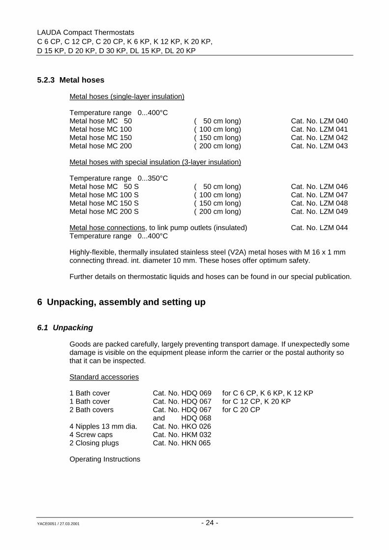
5.2.3 Metal hoses
Metal hoses (single-layer insulation)
Temperature range 0...400°CMetal hose MC 50 ( 50 cm long) Cat. No. LZM 040Metal hose MC 100 ( 100 cm long) Cat. No. LZM 041Metal hose MC 150 ( 150 cm long) Cat. No. LZM 042Metal hose MC 200 ( 200 cm long) Cat. No. LZM 043
Metal hoses with special insulation (3-layer insulation)
Temperature range 0...350°CMetal hose MC 50 S ( 50 cm long) Cat. No. LZM 046Metal hose MC 100 S ( 100 cm long) Cat. No. LZM 047Metal hose MC 150 S ( 150 cm long) Cat. No. LZM 048Metal hose MC 200 S ( 200 cm long) Cat. No. LZM 049
Metal hose connections, to link pump outlets (insulated) Cat. No. LZM 044Temperature range 0...400°C
Highly-flexible, thermally insulated stainless steel (V2A) metal hoses with M 16 x 1 mmconnecting thread. int. diameter 10 mm. These hoses offer optimum safety.
Further details on thermostatic liquids and hoses can be found in our special publication.
6 Unpacking, assembly and setting up
6.1 Unpacking
Goods are packed carefully, largely preventing transport damage. If unexpectedly somedamage is visible on the equipment please inform the carrier or the postal authority sothat it can be inspected.
Standard accessories
1 Bath cover Cat. No. HDQ 069 for C 6 CP, K 6 KP, K 12 KP1 Bath cover Cat. No. HDQ 067 for C 12 CP, K 20 KP2 Bath covers Cat. No. HDQ 067 for C 20 CP
and HDQ 0684 Nipples 13 mm dia. Cat. No. HKO 0264 Screw caps Cat. No. HKM 0322 Closing plugs Cat. No. HKN 065
Operating Instructions
LAUDA Compact ThermostatsC 6 CP, C 12 CP, C 20 CP, K 6 KP, K 12 KP, K 20 KPD 15 KP, D 20 KP, D 30 KP, DL 15 KP, DL 20 KP
YACE0051 / 27.03.2001 - 25 -
6.2 Setting up, operation as bath thermostat
Set up the unit conveniently so that the control panel is towards the front, and ensurethat the air circulation for the refrigeration system through the grille in the lower part ofthe unit and the ventilating openings at the back of the unit is not restricted. A minimumspacing of 20 cm between grille and wall is recommended.
Close the drain cock at the back or at the side of the bath!
When operating as bath thermostat - no external system connected up - it is advisible toensure the internal circulation by removing the closing plugs from the pump flow andreturn connections. Remove the screw caps and link the pump connections togetherusing a piece of hose.
As a permanent arrangement the hose link of flexible insulated metal tubing (Cat. No.LZM 044) is the best and safest solution.For clear-view thermostats: for improved circulation within the bath close the pumpconnections with the closing plugs.
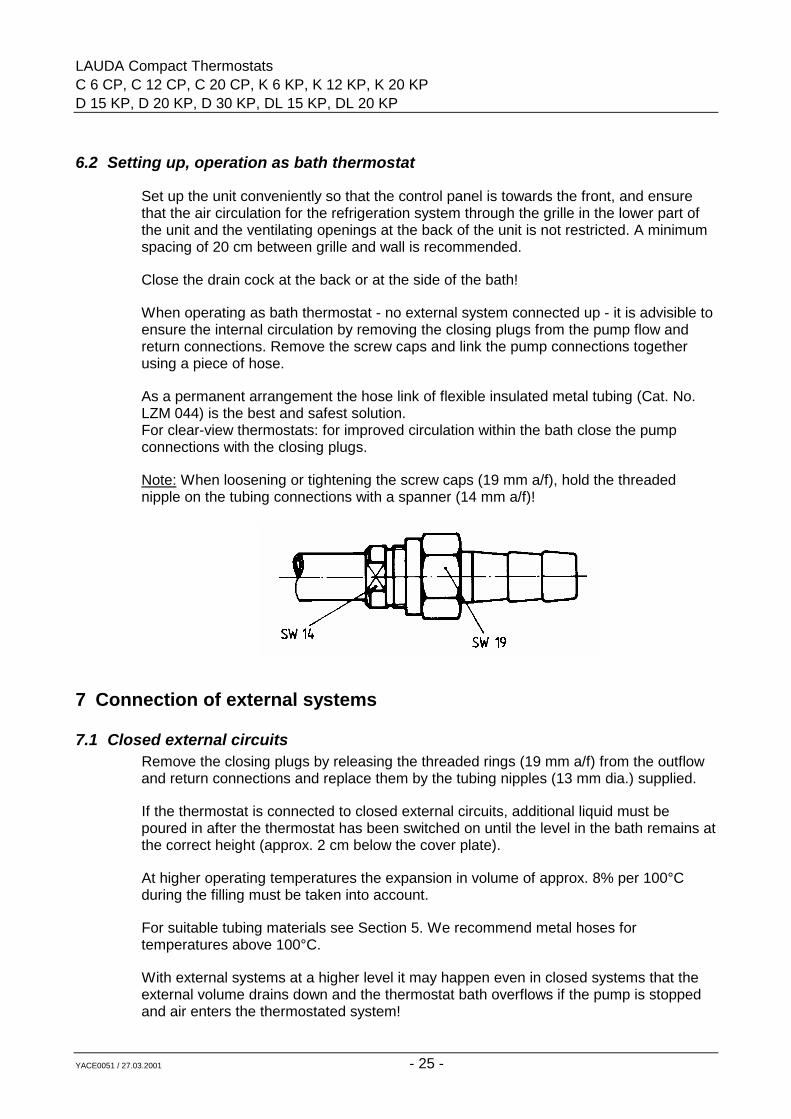
Note: When loosening or tightening the screw caps (19 mm a/f), hold the threadednipple on the tubing connections with a spanner (14 mm a/f)!
7 Connection of external systems
7.1 Closed external circuitsRemove the closing plugs by releasing the threaded rings (19 mm a/f) from the outflowand return connections and replace them by the tubing nipples (13 mm dia.) supplied.
If the thermostat is connected to closed external circuits, additional liquid must bepoured in after the thermostat has been switched on until the level in the bath remains atthe correct height (approx. 2 cm below the cover plate).
At higher operating temperatures the expansion in volume of approx. 8% per 100°Cduring the filling must be taken into account.
For suitable tubing materials see Section 5. We recommend metal hoses fortemperatures above 100°C.
With external systems at a higher level it may happen even in closed systems that theexternal volume drains down and the thermostat bath overflows if the pump is stoppedand air enters the thermostated system!
LAUDA Compact ThermostatsC 6 CP, C 12 CP, C 20 CP, K 6 KP, K 12 KP, K 20 KP,D 15 KP, D 20 KP, D 30 KP, DL 15 KP, DL 20 KP
YACE0051 / 27.03.2001 - 26 -
Always ensure the maximum possible flow area in the external system (nipples, tubing,system). This results in a larger flow and therefore improved thermostatic control.
Note: Always protect the tubing with hose clips against slipping off, or use stainless steelhoses (V2A) with screwed connections.
7.2 Open systems (baths)The units (except K 12 KP) are equipped with a pressure/suction pump. This can beused for the circulation of closed external circuits at higher pump outputs and inparticular also of open external baths. There are two possibilities for maintaining thelevel in external baths:
1. The suction tubing is mounted in the external bath so that its end is at the required liquid level. The flow of the pressure stage is restricted with a tubing clamp on the hose from the pressure connection to the external bath so that flow of the pressure stage is restricted slightly below that of the suction stage. This can be noticed when air enters the suction tubing.
This operating method is not recommended, in particular at temperatures below 0°Cor when using oil at elevated temperatures.
2. The preferred solution is the use of the LAUDA level controller (Cat. No. LPZ 901) which provides the functions of the adjustable level control with float, srew-on connection for external bath, and clamp fitting for 4 mm dia. Pt 100 probe.
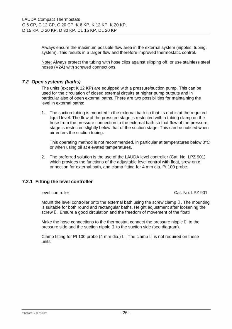
7.2.1 Fitting the level controller
level controller Cat. No. LPZ 901
Mount the level controller onto the external bath using the screw clamp ➀ . The mountingis suitable for both round and rectangular baths. Height adjustment after loosening thescrew ➁ . Ensure a good circulation and the freedom of movement of the float!
Make the hose connections to the thermostat, connect the pressure nipple ➃ to thepressure side and the suction nipple ➄ to the suction side (see diagram).
Clamp fitting for Pt 100 probe (4 mm dia.) ➂ . The clamp ➅ is not required on theseunits!
LAUDA Compact ThermostatsC 6 CP, C 12 CP, C 20 CP, K 6 KP, K 12 KP, K 20 KPD 15 KP, D 20 KP, D 30 KP, DL 15 KP, DL 20 KP
YACE0051 / 27.03.2001 - 27 -
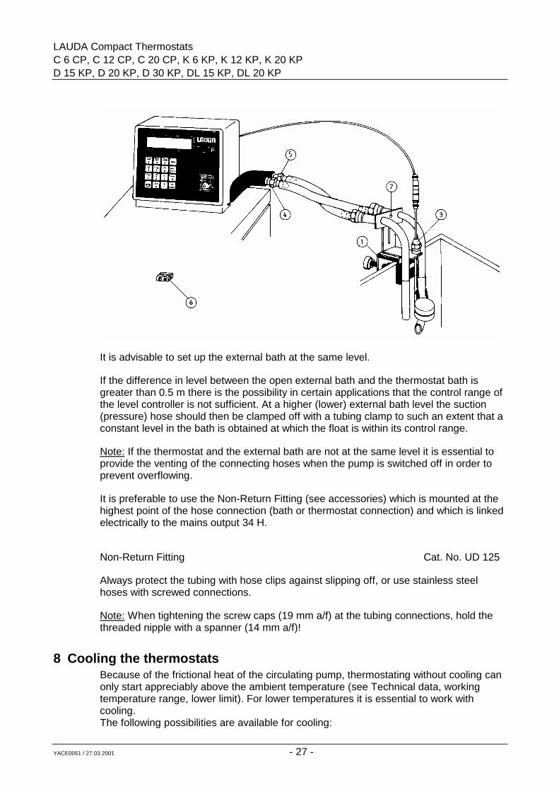
It is advisable to set up the external bath at the same level.
If the difference in level between the open external bath and the thermostat bath isgreater than 0.5 m there is the possibility in certain applications that the control range ofthe level controller is not sufficient. At a higher (lower) external bath level the suction(pressure) hose should then be clamped off with a tubing clamp to such an extent that aconstant level in the bath is obtained at which the float is within its control range.
Note: If the thermostat and the external bath are not at the same level it is essential toprovide the venting of the connecting hoses when the pump is switched off in order toprevent overflowing.
It is preferable to use the Non-Return Fitting (see accessories) which is mounted at thehighest point of the hose connection (bath or thermostat connection) and which is linkedelectrically to the mains output 34 H.
Non-Return Fitting Cat. No. UD 125
Always protect the tubing with hose clips against slipping off, or use stainless steelhoses with screwed connections.
Note: When tightening the screw caps (19 mm a/f) at the tubing connections, hold thethreaded nipple with a spanner (14 mm a/f)!
8 Cooling the thermostatsBecause of the frictional heat of the circulating pump, thermostating without cooling canonly start appreciably above the ambient temperature (see Technical data, workingtemperature range, lower limit). For lower temperatures it is essential to work withcooling.The following possibilities are available for cooling:
LAUDA Compact ThermostatsC 6 CP, C 12 CP, C 20 CP, K 6 KP, K 12 KP, K 20 KP,D 15 KP, D 20 KP, D 30 KP, DL 15 KP, DL 20 KP
YACE0051 / 27.03.2001 - 28 -
8.1 Mains water coolingDepending on the water temperature down to 15°C. The thermostats are equipped witha cooling coil (at the rear) which is linked by tubing to the water tap and to the drain. Theflow should be kept as low as possible; this saves water and improves the temperaturecontrol. Controlled cooling is possible when using a solenoid valve (see Item 3.7)
8.2 Through-flow chillers DLK 10, DLK 25 and DLK 45They can be used, depending on the thermostat type, down to -10°C (DLK 10), -30°C(DLK 25) or -40°C (DLK 45). Use insulated hoses for the connection between the flowand return connections of the pump and the nipples of the through-flow chiller. If thethermostat operates in a closed external circuit the chiller is connected in series in thereturn line from the external system to the thermostat.
Always use water-glycol mixture (ratio 1:1).
9 Starting up
9.1 FillingFill the unit with bath liquid to suit the operating temperature, see Section 5. The fillingvolume is given under Technical data. In general the thermostat must be filled no higherthan 2 cm below the cover plate. When working with thermal oils (e.g. Ultra-Therm 330SCB) slightly less liquid should be filled in because of its expansion. The level mustobviously not fall below the minimum, otherwise the low-level protection switches off theunit (see Safety circuit). The same applies to filling an external system by the pumpduring start-up.Clear-View ThermostatsThe unit has to be switched off and filled up to the filling marks for water or thermal oil.The mark for thermal oil, of course, only refers to the ambient temperature. Whenworking at operating temperatures with the unit switched off the level for thermal oil canalso reach the mark for water. When working with thermal oils slightly less liquid shouldbe filled in because of its expansion. The level must obviously not fall below theminimum, otherwise the low-level protection switches off the unit (see Safety circuit).The same applies to filling an external system by the pump during start-up.
9.2 Connection to supplyConnect the unit only to an earthed socket (PE). Compare the details on the label withthe mains voltage (see Item 4.4.2).
Model according to EMC directive EN 61326-1 (industrial areas only).*
When working without external system, ensure that the pump connections are linkedtogether (metal hose link Cat. No. LZM 044) or closing plugs are being used.
* Notice only valid for EU countries!
LAUDA Compact ThermostatsC 6 CP, C 12 CP, C 20 CP, K 6 KP, K 12 KP, K 20 KPD 15 KP, D 20 KP, D 30 KP, DL 15 KP, DL 20 KP
YACE0051 / 27.03.2001 - 29 -
9.3 Basic functions
9.3.1 Supply switch-onSwitch on the mains switch. The green indicating lamp lights up. The display showsconsecutively
Fa LAUDAP-Thermostat
Type C 6 CP depending on typeV 2.XX Date and software version
L1 Ti = 20.00°C C other values depending onL2 TS= 10.00°C Ti I bath temperature and setpoint
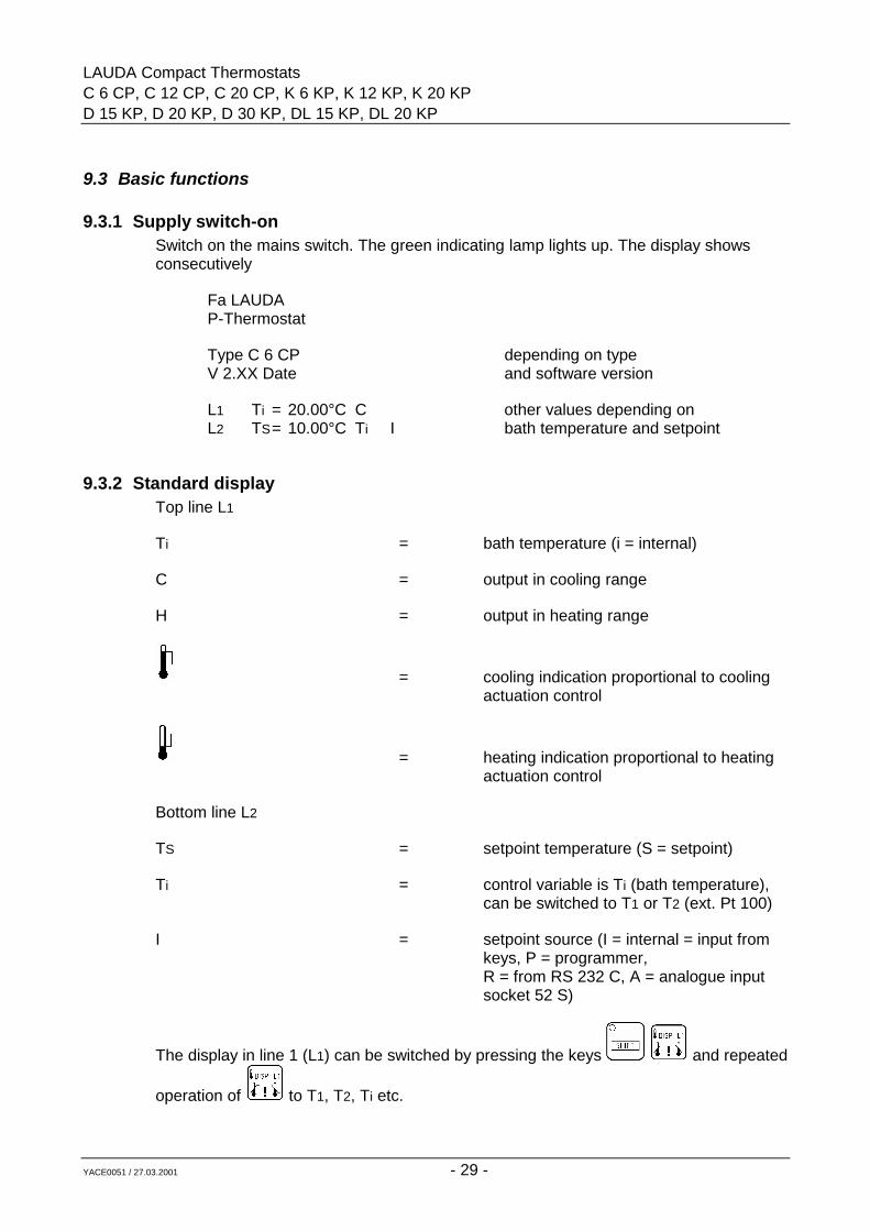
9.3.2 Standard displayTop line L1
Ti = bath temperature (i = internal)
C = output in cooling range
H = output in heating range
= cooling indication proportional to coolingactuation control
= heating indication proportional to heatingactuation control
Bottom line L2
TS = setpoint temperature (S = setpoint)
Ti = control variable is Ti (bath temperature),can be switched to T1 or T2 (ext. Pt 100)
I = setpoint source (I = internal = input fromkeys, P = programmer,R = from RS 232 C, A = analogue inputsocket 52 S)
The display in line 1 (L1) can be switched by pressing the keys and repeated
operation of to T1, T2, Ti etc.
LAUDA Compact ThermostatsC 6 CP, C 12 CP, C 20 CP, K 6 KP, K 12 KP, K 20 KP,D 15 KP, D 20 KP, D 30 KP, DL 15 KP, DL 20 KP
YACE0051 / 27.03.2001 - 30 -
T1, T2 = measurements of external Pt 100 probes
The display in line 2 (L2) can be switched by pressing the keys and repeated
operation of to
Y = actual output + heating - cooling
TSi = measurement of safety comparison probe with limited resolution andaccuracy
Ti, T1, T2, TS etc.
9.3.3 Basic action on inputs and outputs
From virtually every display or input function the key aborts and returns to theselected standard display.
Numerical inputs are always made with the SHIFT function switched off (LED in SHIFTkey off).
After the last digit of a number the cursor returns to the first digit again so that
corrections can easily be made before pressing the key.
A brief beep on pressing a key means that this input is not possible!
Error messages are indicated with text notes and accompanied by a beep. After approx.5 sec the message disappears and the beep switches off!
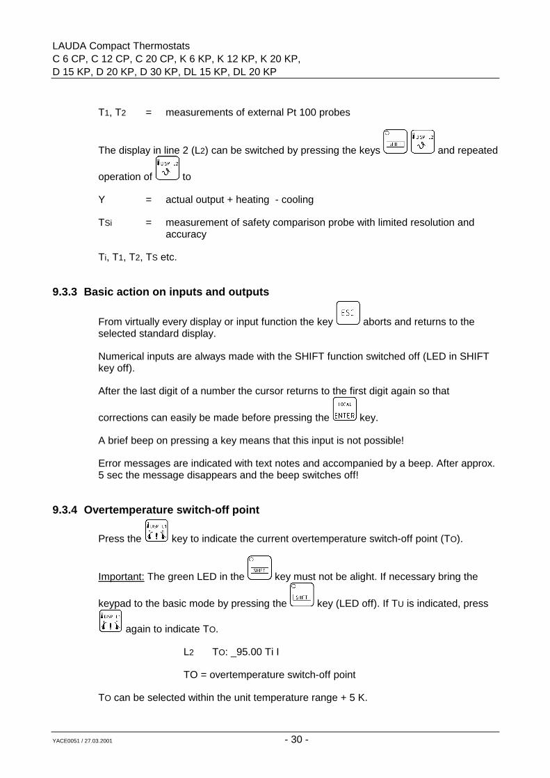
9.3.4 Overtemperature switch-off point
Press the key to indicate the current overtemperature switch-off point (TO).
Important: The green LED in the key must not be alight. If necessary bring the
keypad to the basic mode by pressing the key (LED off). If TU is indicated, press
again to indicate TO.
L2 TO: _95.00 Ti I
TO = overtemperature switch-off point
TO can be selected within the unit temperature range + 5 K.
LAUDA Compact ThermostatsC 6 CP, C 12 CP, C 20 CP, K 6 KP, K 12 KP, K 20 KPD 15 KP, D 20 KP, D 30 KP, DL 15 KP, DL 20 KP
YACE0051 / 27.03.2001 - 31 -
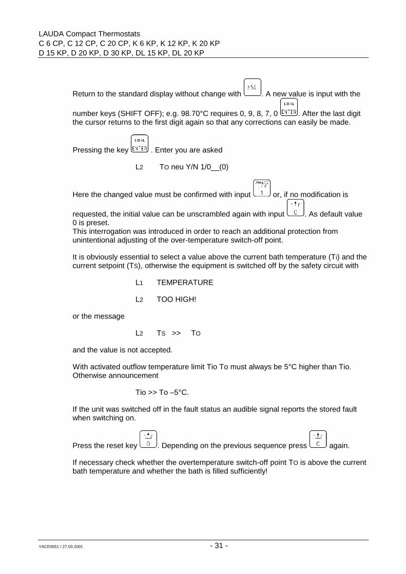
Return to the standard display without change with . A new value is input with the
number keys (SHIFT OFF); e.g. 98.70°C requires 0, 9, 8, 7, 0 . After the last digitthe cursor returns to the first digit again so that any corrections can easily be made.
Pressing the key . Enter you are asked
L2 TO neu Y/N 1/0__(0)
Here the changed value must be confirmed with input or, if no modification is
requested, the initial value can be unscrambled again with input . As default value0 is preset.This interrogation was introduced in order to reach an additional protection fromunintentional adjusting of the over-temperature switch-off point.
It is obviously essential to select a value above the current bath temperature (Ti) and thecurrent setpoint (TS), otherwise the equipment is switched off by the safety circuit with
L1 TEMPERATURE
L2 TOO HIGH!
or the message
L2 TS >> TO
and the value is not accepted.
With activated outflow temperature limit Tio To must always be 5°C higher than Tio.Otherwise announcement
Tio >> To –5°C.
If the unit was switched off in the fault status an audible signal reports the stored faultwhen switching on.
Press the reset key . Depending on the previous sequence press again.
If necessary check whether the overtemperature switch-off point TO is above the currentbath temperature and whether the bath is filled sufficiently!
LAUDA Compact ThermostatsC 6 CP, C 12 CP, C 20 CP, K 6 KP, K 12 KP, K 20 KP,D 15 KP, D 20 KP, D 30 KP, DL 15 KP, DL 20 KP
YACE0051 / 27.03.2001 - 32 -
9.3.5 Low temperature switch-off point
Press the key (SHIFT OFF) to indicate the current low temperature switch-off point
TU. If TO is indicated press again to bring TU on the display.
L2 TU: _-10.00°C
TU = low temperature switch-off point
TU can be set up to 10 K below the working temperature range of the unit.
If the bath temperature falls below TU, TU appears on the display in L2 so that a newvalue can be input if necessary. TU operates as a setpoint limitation and as a signal.
9.3.6 Setpoint input
Press the key (SHIFT LED off). L2 shows
L2 TS: _ 20.00°C Ti I
The setpoint (TS) can be input within the unit temperature range but not higher than the
current overtemperature switch-off point. When the input is too high, pressing does not enter the value but instead produces the message
L2 TS >> TO
Input TS with the number keys and the negative sign (SHIFT OFF), e.g. for -25.03°C
input -, 2, 5, 0, 3 . Or for 1.93°C input 0, 0, 1, 9, 3. After the last digit the cursorreturns to the first digit again so that corrections can easily be made.
9.4 Parameter level PAR
Pressing the key several times in the SHIFT mode (green LED in SHIFT keyalight) leads successively to the input functions described below.
9.4.1 Auto-adaptationHere it is possible to start the controller auto-adaptation by the input of 1 (SHIFT OFF)
and pressing the key.
There should be the largest possible difference between the bath temperature and thesetpoint to be entered subsequently, i.e. the time to reach the setpoint has to be longerthan 5 min, preferably 10 min. In addition, auto-adaptation is obviously possible only
LAUDA Compact ThermostatsC 6 CP, C 12 CP, C 20 CP, K 6 KP, K 12 KP, K 20 KPD 15 KP, D 20 KP, D 30 KP, DL 15 KP, DL 20 KP
YACE0051 / 27.03.2001 - 33 -
during a heating or cooling phase which is actively influenced by the energy sourcesavailable.
Example 1: intended operating temperature approx. 70°C:
1. set the setpoint to 70°C2. within 1 minute start the auto-adaptation at the PAR level, e.g.
at a bath temperature corresponding to the ambient temperature
On reaching the setpoint the auto-adaptation switches off automatically, and the result
of the auto-adaptation can be indicated at the control parameter level (seeItem 9.6).
Example 2: it is required to operate at approx. 20°C with controlled cooling:
1. heat up the thermostat to approx. 60°C2. set the setpoint to 20°C3. start the auto-adaptation at the PAR level
9.4.2 Output limitationNormally the maximum heating or cooling output is available. For special applications itis possible to set a limit for both heating and cooling output.
At the PAR level display select
L1 Output
L2 in per cent_ 100 %
Using the display can be switched from e.g. 100%, i.e. heating output limitation, tocooling output limitation with a negative sign.
By the input of e.g. 0, 0, 5, 8 , SHIFT OFF, a heating output limitation of 58% canbe set.
With e.g. -, 0, 9, 3 a cooling output limitation of 93% is entered.
The action can be recognised by the symbols and flashing even at large controldeviations.
Only values between 10 and 100% or -10 and -100% can be entered, otherwise thedisplay shows the message
L1 Output
LAUDA Compact ThermostatsC 6 CP, C 12 CP, C 20 CP, K 6 KP, K 12 KP, K 20 KP,D 15 KP, D 20 KP, D 30 KP, DL 15 KP, DL 20 KP
YACE0051 / 27.03.2001 - 34 -
L2 OUT OF RANGE
9.4.3 Display resolution L1At the PAR level display select
L1 Display 0.001 = 1
L2 resolution 0.01 = 0
Entering 1 (SHIFT OFF) switches all displays in L1 to 0.001 K resolution. Thetemperatures are then displayed with approx. 2 digit resolution. Input "0" switches all thedisplays in L1 to 0.01 K resolution.
Normally a resolution of 0.01 K is used.
9.4.4 Contact input Fault 14 NWhen using the contact input "FAULT" 14 N, pins 1 and 2 of the socket have to beconnected together when there is no fault. If this input is not being used, a blanking plugwith a link has to be plugged in. The function of the contact input fault can be switchedoff at the PAR level on the display
L1 Alarm Inp. con 14 N
L2 on = 1 off = 0
by the input of "0" (SHIFT OFF). A shorting plus is then not required.
If the alarm input has been activated in error by the input of "1", the unit can be restartedby the following inputs:
Press the key . At the PAR level select "Alarm Inp. con 14 N". Input "0" with .
Press again.
If a fault message has been produced by opening the external signal circuit, reset by
pressing the key twice after rectifying the fault.
Connections contact input "Fault" 14 N (alarm in)
3-pin flange socket to NAMUR recommendation NE 28
1 = n.o. (close)2 = common3 = not used
LAUDA Compact ThermostatsC 6 CP, C 12 CP, C 20 CP, K 6 KP, K 12 KP, K 20 KPD 15 KP, D 20 KP, D 30 KP, DL 15 KP, DL 20 KP
YACE0051 / 27.03.2001 - 35 -
Connector plug 3-pin Cat. No. EQS 048
Contact load approx. 5 V 2 mA. No voltage must be connected!
Use shielded connecting cables. Connect the shielding to the plug case. Cover theunused connectors with protective caps!
9.4.5 Baud rate RS 232On the display at the PAR level
L1 Ser. Int RS 232
L2 Baud Rate 9600
it is possible to switch with between 9600 and 4800. With (SHIFT OFF) theindicated baud rate is entered.
9.4.6 Menu languageOn the display at the PAR level
L1 Lang. Germ = 0
L2 Engl = 1 French = 2
the menu language can be selected. Enter the corresponding code numbers 0, 1 or 2
with (SHIFT OFF).
9.4.7 Calibrating the analogue output channelsThe 90% values of the analogue voltage outputs channel 1 and 2 or the analoguecurrent output of channel 1 can be calibrated separately for channel 1 (voltage orcurrent) and channel 2 (voltage). The factory calibration on channels 1 and 2 for0...10 V = -100...400°C is performed at 9 V = 350°C.
In special cases, e.g. to correct scaling deviations of instruments connected to theoutput, or if channel 1 is to be a current output, the output can be calibrated by the user.
At the PAR level display select
L1 Analogue outp Cal ?
L2 Chan 1 = 1 Chan 2 = 2
Input SHIFT OFF 1 , or 2 for channel 2.
LAUDA Compact ThermostatsC 6 CP, C 12 CP, C 20 CP, K 6 KP, K 12 KP, K 20 KP,D 15 KP, D 20 KP, D 30 KP, DL 15 KP, DL 20 KP
YACE0051 / 27.03.2001 - 36 -
Depending on the selected configuration of the analogue outputs (see Item 9.12) thesocket 52 S (analogue signals, see Item 9.10) at pin 2 carries a voltage signal of approx.95% or 9.5 V, or pin 5 the corresponding current signal of approx. 19 mA in case ofcurrent configuration for channel 1.
Using a precision multimeter or e.g. a temperature recorder set the output signal to 9 V
or 18 mA or the corresponding temperature by the repeated operation of the key (SHIFT ON).
Pressing leaves the menu and the most recent value setting is entered.
If the value was selected too low, leave the PAR level with and make a newselection.
The calibration of channel 2 is similar. Connect the measuring instrument to pin 1(voltage signal only).
9.4.8 Operation with through-flow chiller DLK 45 with proportional coolingAt the PAR level display select
L1 DLK normal = 0
L2 DLK 45 auto = 1
Select „DLK normal“ by pressing 0 in order to have the function as already known of thetwo outputs 19 H and 34 H.
Select „DLK auto“ by pressing 1 in order to operate a through-flow chiller DLK 45 withautomatic compressor control and proportional cooling; see also operating instructionsof the through-flow chillers.
9.5 Calibration of the temperature measurement circuitsWith the calibration function the indications of the three temperature measuring pointsbath temperature Ti, external Pt 100 probe T1 and external Pt 100 probe T2 can be setto a known accurate value. The resulting correction is processed additively over theentire temperature range.
Check first that a sufficiently accurate reference is available, otherwise it is better to usethe factory calibration which gets lost by overwriting!
Pressing the key in the SHIFT mode (green LED in shift key alight) produces thedisplay
L1 CALIBRATE
LAUDA Compact ThermostatsC 6 CP, C 12 CP, C 20 CP, K 6 KP, K 12 KP, K 20 KPD 15 KP, D 20 KP, D 30 KP, DL 15 KP, DL 20 KP
YACE0051 / 27.03.2001 - 37 -
L2 Ti = 0 T1 = 1 T2 = 2
The channel to be calibrated is selected with 0, 1 or 2 .
When selecting an unused channel, e.g. if Pt 100 on T2 is not connected, the displayshows
L1 Ext Pt 100 not
L2 connected
For calibration a sufficiently accurate reference temperature measurement should bepossible, and the measurement point temperature should be constant.
The display shows
L1 T1 61.04°C
L2 TC _ . °C
The value shown in L1 is the measured value obtained without any correction usingprobe and electronics without calibration. Now enter the real value for the measurementpoint T1 (e.g. 60.00°C):
Example: 0, 6, 0, 0, 0
Ti or T2 can be calibrated in the same way.
In order to avoid dangerous conditions the correction is limited to +5 K. In case of largercorrections the display shows
L1 CORRECTION VALUE
L2 TOO LARGE
and the entered value is not accepted.
You can leave the calibration level with .
9.6 Control parameters
9.6.1 Indication and input of the control parameters
Pressing the key several times in the SHIFT mode (green LED in shift key alight)shows the outflow temperature limitation, the correction limitation and the controlparameters Xp, Tn and Tv on the display in L2.
LAUDA Compact ThermostatsC 6 CP, C 12 CP, C 20 CP, K 6 KP, K 12 KP, K 20 KP,D 15 KP, D 20 KP, D 30 KP, DL 15 KP, DL 20 KP
YACE0051 / 27.03.2001 - 38 -
Example:
L2 TiO: 120°C Ti I
L2 Td: _ 30°C Ti I
L2 Xp: _ 0.5°C Ti I
L2 Tn: _ 12.0 s Ti I
L2 Tv: _ 2.0 s Ti I
In order to use control parameters other than those found by auto-adaptation (seeItem 9.4.1) the values can be entered in the appropriate display after switching off the
SHIFT function, pressing , LED off.
Example for Xp:
0, 0, 1, 0
if the required value is 1.0°C.
For values above 200.0°C or 200.0 sec the message
L2 OUT OF RANGE
appears.
9.6.2 Recommendations for the control parametersIn most cases satisfactory control results are obtained with the following controlparameters:
bath liquid water oil
Xp 0.5°C 1°CTn 10 s 25 sTv 2 s 5 s
9.6.3 Bath temperature limitationThe limitation of the bath temperature is an additional warning and switch-off functionswitching off the heating at a selectable value; i.e. the heating output is set to "0". Thisprotects the unit from a continuous cut-off via the safety circuit especially during externalcontrol at certain operating conditions.
To enter the switch-off point TiO proceed as described in Item 9.6.1, and switch thedisplay to input and indication.
LAUDA Compact ThermostatsC 6 CP, C 12 CP, C 20 CP, K 6 KP, K 12 KP, K 20 KPD 15 KP, D 20 KP, D 30 KP, DL 15 KP, DL 20 KP
YACE0051 / 27.03.2001 - 39 -
Example: L2 TiO 120°C
Change the value by entering numerical inputs with a resolution of 1°C.
Enter the new value by pressing .
It is possible to select values within a range from 50°C to the selected overtemperatureswitch-off point TO -5°C. If this range has not been respected the display shows themessage
L2 TiO >> TO - 5 °C
Of course TiO has to be set above the setpoint TS; otherwise the display shows themessage
L2 TS > TiO
The bath temperature limitation can be switched off by entering
L2 TiO 000
If the bath temperature Ti exceeds the selected switch-off point the display shows
Example:L2 TiO 120 °C
and there is an acoustic signal.
The heater switches off. As soon as the temperature has dropped the unit starts workingagain.
9.6.4 Correction limitationDuring the operation with external control it may be necessary not to exceed thedifference between the bath temperature Ti and the measuring point for the externalcontrol T1 or T2, e.g. in order to get a smooth heating of the material or the vessel.
Such a value can be selected by the variable Td. If the value Td is exceeded the heatingor cooling output is set to "0". If this function is activated the times for heating up orcooling down may be extended.
To enter the difference value Td, proceed as described in Item 9.6.1 and switch thedisplay to input and indication.
Example: L2 Td _30°C
Change the value by entering numerical inputs with a resolution of 1°C.
Enter the new value by pressing .
LAUDA Compact ThermostatsC 6 CP, C 12 CP, C 20 CP, K 6 KP, K 12 KP, K 20 KP,D 15 KP, D 20 KP, D 30 KP, DL 15 KP, DL 20 KP
YACE0051 / 27.03.2001 - 40 -
It is possible to select values within the temperature range from 5°C to 150°C. If thisrange has not been respected the display shows
L2 OUT OF RANGE
and there is an acoustic signal.
This function can be switched off by entering
L2 Td 000 °C
9.7 External control
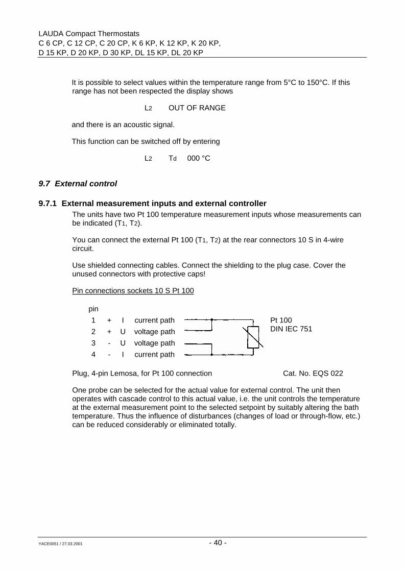
9.7.1 External measurement inputs and external controllerThe units have two Pt 100 temperature measurement inputs whose measurements canbe indicated (T1, T2).
You can connect the external Pt 100 (T1, T2) at the rear connectors 10 S in 4-wirecircuit.
Use shielded connecting cables. Connect the shielding to the plug case. Cover theunused connectors with protective caps!
Pin connections sockets 10 S Pt 100
pin1234
++--
IUUI
current pathvoltage pathvoltage pathcurrent path
Pt 100DIN IEC 751
Plug, 4-pin Lemosa, for Pt 100 connection Cat. No. EQS 022
One probe can be selected for the actual value for external control. The unit thenoperates with cascade control to this actual value, i.e. the unit controls the temperatureat the external measurement point to the selected setpoint by suitably altering the bathtemperature. Thus the influence of disturbances (changes of load or through-flow, etc.)can be reduced considerably or eliminated totally.
LAUDA Compact ThermostatsC 6 CP, C 12 CP, C 20 CP, K 6 KP, K 12 KP, K 20 KPD 15 KP, D 20 KP, D 30 KP, DL 15 KP, DL 20 KP
YACE0051 / 27.03.2001 - 41 -
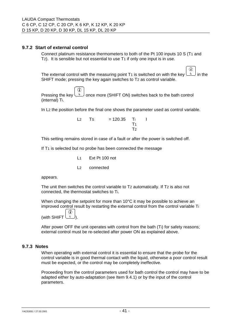
9.7.2 Start of external controlConnect platinum resistance thermometers to both of the Pt 100 inputs 10 S (T1 andT2). It is sensible but not essential to use T1 if only one input is in use.
The external control with the measuring point T1 is switched on with the key in theSHIFT mode; pressing the key again switches to T2 as control variable.
Pressing the key once more (SHIFT ON) switches back to the bath control(internal) Ti.
In L2 the position before the final one shows the parameter used as control variable.
L2 TS = 120.35 Ti IT1T2
This setting remains stored in case of a fault or after the power is switched off.
If T1 is selected but no probe has been connected the message
L1 Ext Pt 100 not
L2 connected
appears.
The unit then switches the control variable to T2 automatically. If T2 is also notconnected, the thermostat switches to Ti.
When changing the setpoint for more than 10°C it may be possible to achieve animproved control result by restarting the external control from the control variable Ti
(with SHIFT ).
After power OFF the unit operates with control from the bath (Ti) for safety reasons;external control must be re-selected after power ON as explained above.
9.7.3 NotesWhen operating with external control it is essential to ensure that the probe for thecontrol variable is in good thermal contact with the liquid, otherwise a poor control resultmust be expected, or the control may be completely ineffective.
Proceeding from the control parameters used for bath control the control may have to beadapted either by auto-adaptation (see Item 9.4.1) or by the input of the controlparameters.
LAUDA Compact ThermostatsC 6 CP, C 12 CP, C 20 CP, K 6 KP, K 12 KP, K 20 KP,D 15 KP, D 20 KP, D 30 KP, DL 15 KP, DL 20 KP
YACE0051 / 27.03.2001 - 42 -
Important: set the overtemperature switch-off point TO (see Item 9.3.4) sufficiently highsince the bath temperature may under certain circumstances become much higher thanthe setpoint.
9.8 Working with controlled coolingOperation with controlled cooling requires a solenoid valve.
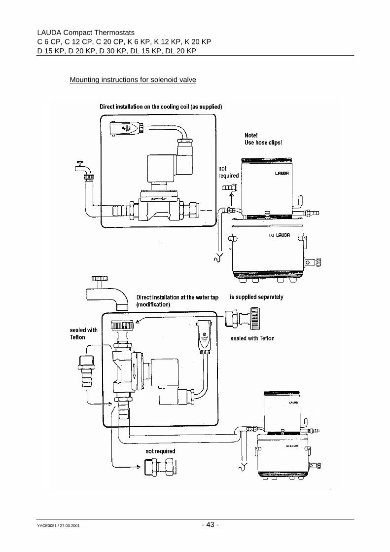
Insert the plug of the solenoid valve into the socket (19 H) on the back. The solenoidvalve can be fitted either on the cooling coil or on a 1/2" water tap. Although fitting onthe cooling coil is the usual method, mounting directly on the water tap is preferable fortwo reasons: When the valve is closed, the connection hose to the cooling coil is notunder pressure; therefore there will not be a pressure surge when the valve is switchedon, and the danger of the hose bursting is much reduced. Use hose clips!
With controlled cooling operation the solenoid valve switches with a cycle time of about
6 s. L1 indicates on the right the symbol for the status of the solenoid valve. Restrictthe water flow as much as possible at the water tap. This produces improved control andsaves cooling water.
Note: Ensure that the cooling coil connections are used. Do not mix them up withthe pump connectors!
It is essential to ensure free outflow from the cooling coil, especially at operatingtemperatures above 100°C because of steam formation! The use of controlled cooling isparticularly helpful when initiating exthermal reactions or in programmer operation.
Solenoid valve for cooling water control Cat. No. UD 085
Mating plug for other solenoid valve Cat. No. EQS 005
LAUDA Compact ThermostatsC 6 CP, C 12 CP, C 20 CP, K 6 KP, K 12 KP, K 20 KPD 15 KP, D 20 KP, D 30 KP, DL 15 KP, DL 20 KP
YACE0051 / 27.03.2001 - 43 -
Mounting instructions for solenoid valve
LAUDA Compact ThermostatsC 6 CP, C 12 CP, C 20 CP, K 6 KP, K 12 KP, K 20 KP,D 15 KP, D 20 KP, D 30 KP, DL 15 KP, DL 20 KP
YACE0051 / 27.03.2001 - 44 -
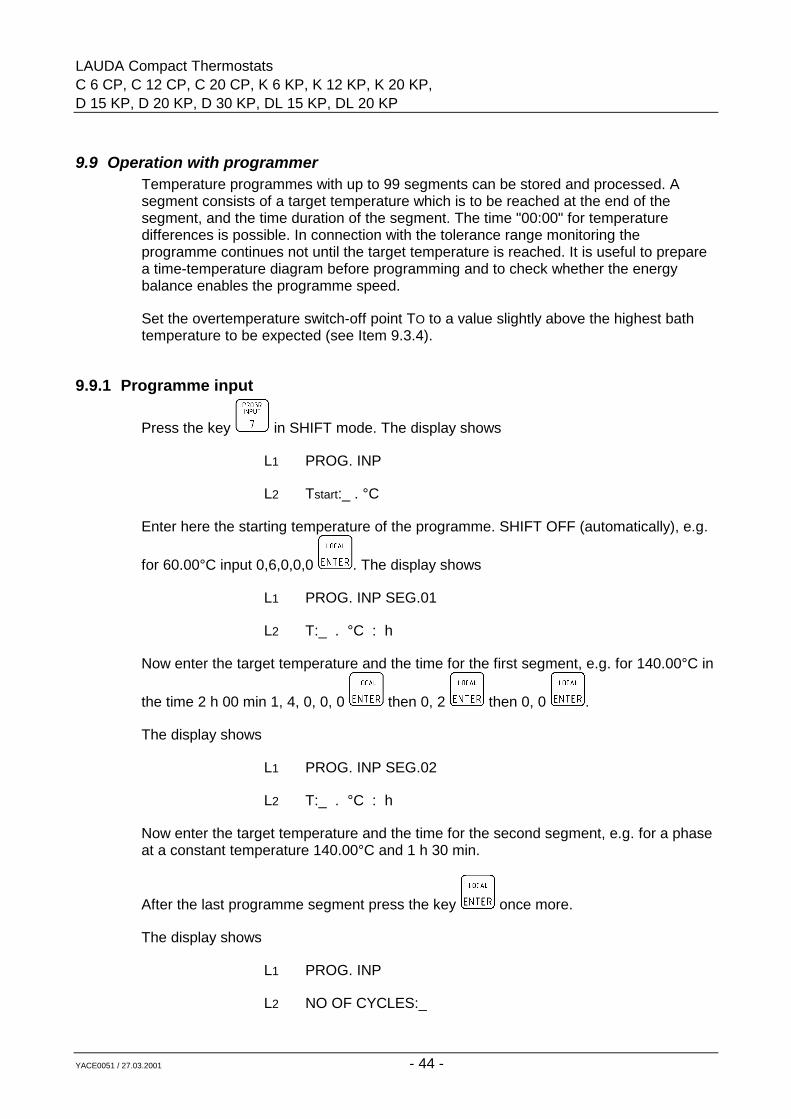
9.9 Operation with programmerTemperature programmes with up to 99 segments can be stored and processed. Asegment consists of a target temperature which is to be reached at the end of thesegment, and the time duration of the segment. The time "00:00" for temperaturedifferences is possible. In connection with the tolerance range monitoring theprogramme continues not until the target temperature is reached. It is useful to preparea time-temperature diagram before programming and to check whether the energybalance enables the programme speed.
Set the overtemperature switch-off point TO to a value slightly above the highest bathtemperature to be expected (see Item 9.3.4).
9.9.1 Programme input
Press the key in SHIFT mode. The display shows
L1 PROG. INP
L2 Tstart:_ . °C
Enter here the starting temperature of the programme. SHIFT OFF (automatically), e.g.
for 60.00°C input 0,6,0,0,0 . The display shows
L1 PROG. INP SEG.01
L2 T:_ . °C : h
Now enter the target temperature and the time for the first segment, e.g. for 140.00°C in
the time 2 h 00 min 1, 4, 0, 0, 0 then 0, 2 then 0, 0 .
The display shows
L1 PROG. INP SEG.02
L2 T:_ . °C : h
Now enter the target temperature and the time for the second segment, e.g. for a phaseat a constant temperature 140.00°C and 1 h 30 min.
After the last programme segment press the key once more.
The display shows
L1 PROG. INP
L2 NO OF CYCLES:_
LAUDA Compact ThermostatsC 6 CP, C 12 CP, C 20 CP, K 6 KP, K 12 KP, K 20 KPD 15 KP, D 20 KP, D 30 KP, DL 15 KP, DL 20 KP
YACE0051 / 27.03.2001 - 45 -
Input 1 ... 99 is possible.
With more than one cycle it is convenient to have the final temperature and the startingtemperature Tstart at the same level!
Afterwards a tolerance range can be input for monitoring the programme.
The display shows
L1 PROG. INP
L2 TOL. RANGE_.
Now you can input a tolerance range value from 0.1 to 9.9°C. I.e. if the control variable(bath temperature or external temperature T1 or T2) deviates from the set temperatureof the segment by more than the tolerance range value while the programme is running,the proramme sequence will be stopped until the control variable is within the tolerancerange again.At the same time a "T" appears on the right in L2.
The input of 0.0 switches off the tolerance range function.
LAUDA Compact ThermostatsC 6 CP, C 12 CP, C 20 CP, K 6 KP, K 12 KP, K 20 KP,D 15 KP, D 20 KP, D 30 KP, DL 15 KP, DL 20 KP
YACE0051 / 27.03.2001 - 46 -
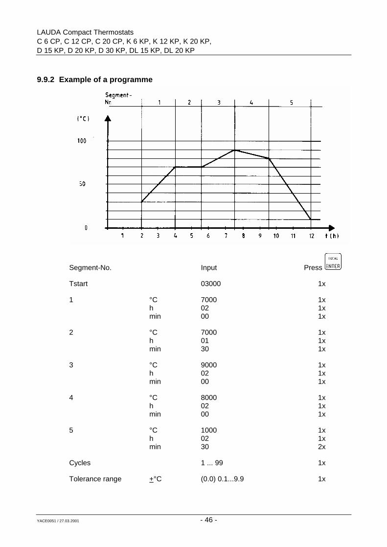
9.9.2 Example of a programme
Segment-No. Input Press
Tstart 03000 1x
1 °C 7000 1xh 02 1xmin 00 1x
2 °C 7000 1xh 01 1xmin 30 1x
3 °C 9000 1xh 02 1xmin 00 1x
4 °C 8000 1xh 02 1xmin 00 1x
5 °C 1000 1xh 02 1xmin 30 2x
Cycles 1 ... 99 1x
Tolerance range +°C (0.0) 0.1...9.9 1x
LAUDA Compact ThermostatsC 6 CP, C 12 CP, C 20 CP, K 6 KP, K 12 KP, K 20 KPD 15 KP, D 20 KP, D 30 KP, DL 15 KP, DL 20 KP
YACE0051 / 27.03.2001 - 47 -
9.9.3 Programme testAfter the input of the programme it is advisable to check that the programme buffer
contains the correct data. This is done with the key in the SHIFT mode.
Pressing the key repeatedly produces the same sequence as during the input of theprogramme.
9.9.4 Changing the programme dataSelect the data line to be changed as in "programme test", SHIFT OFF. This resets thedata of the indicated segment. Then the data can be input as usual. Enter the new data
with each.
9.9.5 Programme start, interruption and abortIt is useful to bring the operating temperature of the thermostat to the programme starttemperature Tstart before starting the programme, or to automatize it by the tolerancerange function.
Start the programme sequence with in the SHIFT mode. The programmesequence can then be followed by the indication of the setpoint TS.
L1 shows on the right the segment number, and L2 shows as a setpoint source a P for"programme" on the right.
The keys 1 to 9 are blocked while the programme is running.
The sequence of the programme can be stopped with SHIFT and then be re-
started with SHIFT .
During the interruption of the programme the display shows a W (wait) on the right in L2.
The programme can be aborted with and then SHIFT within 2 sec.Afterwards the programme can only be started with segment 1.
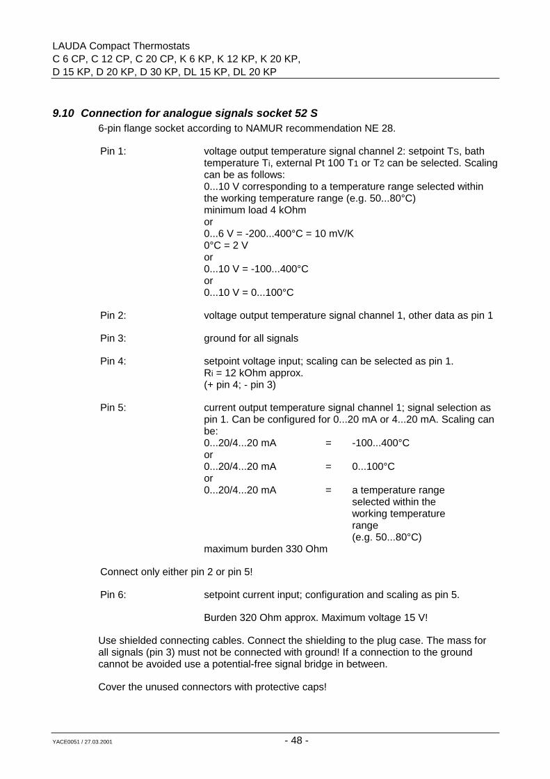
LAUDA Compact ThermostatsC 6 CP, C 12 CP, C 20 CP, K 6 KP, K 12 KP, K 20 KP,D 15 KP, D 20 KP, D 30 KP, DL 15 KP, DL 20 KP
YACE0051 / 27.03.2001 - 48 -
9.10 Connection for analogue signals socket 52 S6-pin flange socket according to NAMUR recommendation NE 28.
Pin 1: voltage output temperature signal channel 2: setpoint TS, bathtemperature Ti, external Pt 100 T1 or T2 can be selected. Scalingcan be as follows:0...10 V corresponding to a temperature range selected withinthe working temperature range (e.g. 50...80°C)minimum load 4 kOhmor0...6 V = -200...400°C = 10 mV/K0°C = 2 Vor0...10 V = -100...400°Cor0...10 V = 0...100°C
Pin 2: voltage output temperature signal channel 1, other data as pin 1
Pin 3: ground for all signals
Pin 4: setpoint voltage input; scaling can be selected as pin 1.Ri = 12 kOhm approx.(+ pin 4; - pin 3)
Pin 5: current output temperature signal channel 1; signal selection aspin 1. Can be configured for 0...20 mA or 4...20 mA. Scaling canbe:0...20/4...20 mA = -100...400°Cor0...20/4...20 mA = 0...100°Cor0...20/4...20 mA = a temperature range
selected within theworking temperaturerange(e.g. 50...80°C)
maximum burden 330 Ohm
Connect only either pin 2 or pin 5!
Pin 6: setpoint current input; configuration and scaling as pin 5.
Burden 320 Ohm approx. Maximum voltage 15 V!
Use shielded connecting cables. Connect the shielding to the plug case. The mass forall signals (pin 3) must not be connected with ground! If a connection to the groundcannot be avoided use a potential-free signal bridge in between.
Cover the unused connectors with protective caps!
LAUDA Compact ThermostatsC 6 CP, C 12 CP, C 20 CP, K 6 KP, K 12 KP, K 20 KPD 15 KP, D 20 KP, D 30 KP, DL 15 KP, DL 20 KP
YACE0051 / 27.03.2001 - 49 -
Connector plug, 6-pin Cat. No. EQS 057
9.11 Analogue inputsA setpoint in the form of an analogue current or voltage signal can be provided byconnection to the socket "Temp.-Signal" 52 S (see Item 9.10).
By pressing the key in the SHIFT mode the display shows
L1 ANALOGUE INP/OUTP
L2 INP = 0 OFF = 1_
Pressing 0 selects the configuration and scaling of a setpoint input.
The display shows
L1 ANALOG INP. OFF = 0
L2 ON = 1 CONF = 2_.
Input 1 switches in a previously configured input as setpoint, and L2 shows an "A"at the right end, indicating that the setpoint is determined by the analogue input.
This condition remains stored in case of a fault or after the power is switched off.
Input 0 switches the setpoint back to setpoint source I internal, i.e. key input.
Scaling takes place interactively by applying the voltage and current valuescorresponding to the appropriate temperature range limits to the corresponding input.For pin connections for voltage or current input on socket 52 S see Item 9.10. Thismethod compensates various scaling errors, e.g. also those of the sources connected.
Pressing 2 configures and scales the setpoint input. The display shows
L1 ANALOG INPUT
L2 U = 0 I = 1
Select a voltage range with 0 . Voltages in the range 0...10.5 V can be handled.
A current range is selected with 1 . Currents in the range 0...22 mA can behandled.
LAUDA Compact ThermostatsC 6 CP, C 12 CP, C 20 CP, K 6 KP, K 12 KP, K 20 KP,D 15 KP, D 20 KP, D 30 KP, DL 15 KP, DL 20 KP
YACE0051 / 27.03.2001 - 50 -
The display shows
L1 ANALOG INPUT
L2 Tmin = _ . °C
Input the lowest temperature of the range which corresponds to the lowest voltage orcurrent value of the range to be scaled.
Example: range 0...120°C should correspond to 0...10 V approx.
Input 0, 0, 0, 0, 0 .
The display shows
L1 ANALOG INPUT
L2 Tmax = _ . °C
Input the upper limit of the temperature range 1, 2, 0, 0, 0
If the current input is selected, the programme asks whether 0...20 mA or 4...20 mA isrequired.
The display shows
L1 CURRENT INPUT
L2 0-20 = 0 4-20 = 1
Select 0 or 1 . This menu item is omitted when the voltage input has beenselected.
The display shows
L1 INPUT CAL.?
L2 YES = 1 NO = 0
Here the decision is made whether an automatic calibration procedure is started, orwhether the voltage or current values from the last calibration procedure are retained
with input 0 .
The display returns to the standard display.
With a new calibration the voltage or current source (e.g. setpoint unit, programmer)must be connected up. The range limits must be adjustable.
LAUDA Compact ThermostatsC 6 CP, C 12 CP, C 20 CP, K 6 KP, K 12 KP, K 20 KPD 15 KP, D 20 KP, D 30 KP, DL 15 KP, DL 20 KP
YACE0051 / 27.03.2001 - 51 -
The unit may switch to fault if the input signal is not connected. If this is the case it is
necessary to connect the input signal first. Then press the reset key and calibratein the same way as described above.
Select recalibration with 1 .
The display shows
L1 SET Umin
L2 YES = 1
When the voltage or current corresponding to the lower range limit is applied to the
input, confirm this by input of 1 .
The display shows
L1 ------------wait-----------
L2 XXXXXXXXXXXXXX
The calibration takes approx. 20 sec. Then the display shows
L1 SET Umax
L2 YES = 1
When the voltage or current corresponding to the upper range limit is applied to the
input, confirm this by input of 1 .
The display shows
L1 ------------wait-----------
L2 XXXXXXXXXXXXXX
The calibration takes approx. 60 sec. Then the display returns to the standard display.The calibration is finished.
Switch-on the external setpoint from an analogue input as described in Item 9.11.2.
LAUDA Compact ThermostatsC 6 CP, C 12 CP, C 20 CP, K 6 KP, K 12 KP, K 20 KP,D 15 KP, D 20 KP, D 30 KP, DL 15 KP, DL 20 KP
YACE0051 / 27.03.2001 - 52 -
9.12 Analogue outputsTwo analogue output channels are available at the socket "Temp.-Signal" 52 S (seeItem 9.10). They can be set to carry the temperature values
Ti = bath temperature
T1 = temperature at ext. Pt 100 T1
T2 = temperature at ext. Pt 100 T2
TS = setpoint
9.12.1 Temperature signal channel 1Channel 1 can be configured at socket 52 S on pin 2 as voltage output or on pin 5 as
current output. Press key in SHIFT mode.
The display shows
L1 ANALOG INP/OUTP
L2 INP = 0 OUTP = 1
Select the processing of the outputs by pressing 1 . The display shows
L1 Analog outputs
L2 Chan 1=1 Chan 2=2
Select channel 1 by pressing 1 . The display shows
L1 Analog output
L2 U = 0 I = 1_
Select the current output with 1 . The display shows
L1 CURRENT OUTPUT
L2 0-20=0 4-20=1
Select the required current range 0...20 mA or 4...20 mA by pressing 0 or 1 .
The current range selection is omitted if the voltage range 0...10 V has been selected inthe previous menu. The display shows the scalings available for selection
LAUDA Compact ThermostatsC 6 CP, C 12 CP, C 20 CP, K 6 KP, K 12 KP, K 20 KPD 15 KP, D 20 KP, D 30 KP, DL 15 KP, DL 20 KP
YACE0051 / 27.03.2001 - 53 -
L1 CONFIGURABLE=1
L2 analog output_
By pressing the key (SHIFT ON) the pre-set scalings are displayed consecutively.
The selection is made by the input of the appropriate code (SHIFT OFF).
Configurable means that the temperature range required to correspond to the voltagerange 0...10 V, current range 0...20 mA or 4...20 mA can be determined by setting therange start (Tmin) and the range end (Tmax).
The display shows
L1 CONFIGURABLE=1
L2 Tmin =_ . °C
Example: range 20...220°C
Input 0, 2, 0, 0, 0 . The display shows
L2 Tmax =_ . °C
Input 2, 2, 0, 0, 0 .
The following fixed scalings are available:
-200...400°C = 0...6 V = 10 mV/K0°C = 2 V Code 2
-100...400°C = 0...10 V or 0...20 mA or 4...20 mA Code 3
0...100°C = 0...10 V or 0...20 mA or 4...20 mA Code 4
The display then shows
L2 Ti T1 T2 TS 0-3_
E.g. to set the bath temperature on channel 1 input 0 . Similarly for the
temperature signal of the external Pt 100 T1 input 1 etc. The display then returnsto the standard display.
LAUDA Compact ThermostatsC 6 CP, C 12 CP, C 20 CP, K 6 KP, K 12 KP, K 20 KP,D 15 KP, D 20 KP, D 30 KP, DL 15 KP, DL 20 KP
YACE0051 / 27.03.2001 - 54 -
9.12.2 Temperature signal channel 2Channel 2 is purely a voltage output at socket 52 S on pin 1. The selection is made asdescribed for channel 1 in Item 9.12.1 except that current ranges cannot be selected.
9.13 Safety functionThe operation of the safety devices of the units has already been described underItem 4.1.
After starting up the user should confirm the correct operation of the safety devices. Ifthe unit operates without supervision we recommend that this check should be carriedout daily.
9.13.1 Low-level cut-outFor a correct operation of the low-level cut-out it is essential that the float switchoperates correctly. To check this, lower the level in the bath by draining away some ofthe liquid. When the bath level falls below the minimum level (approx. 20 mm above theupper heater winding) the pump, the heating and the refrigeration unit switch off on allpoles.
The display shows the message
L1 LEVEL
L2 TOO LOW
and there is a warning beep.
To restart fill up the bath and press the reset key twice (with approx. 1 secinterval).
9.13.2 Adjustable overtemperature limiterTo check it the switch-off point TO has to be set below the current bath temperature.Note that an input of TO below the setpoint TS produces the message
L2 TS >> TO
and the previous value for TO is retained. Therefore the setpoint TS usually has to belowered first by a few degrees before carrying out this test. The overtemperature switch-off point can then be set e.g. 1 K below the current bath temperature.
Example: Ti = 60°C
TS = 60°C
TO = 65°C
LAUDA Compact ThermostatsC 6 CP, C 12 CP, C 20 CP, K 6 KP, K 12 KP, K 20 KPD 15 KP, D 20 KP, D 30 KP, DL 15 KP, DL 20 KP
YACE0051 / 27.03.2001 - 55 -
To check the operation of the overtemperature limiter, press (SHIFT OFF). Input
TS = 20°C, press , the display shows
L1 Ti = 60.00°C C
L2 TO : 65.00°C Ti I
If Tu is shown in L2, press again!
Now input 0, 5, 8, 0, 0 .
The switch-off point of the overtemperature limiter is now 2 K below the bathtemperature Ti.
The display shows the message
L1 TEMPERATURE
L2 TOO HIGH!
with a beep. Heating and pump are switched off on all poles.
To restart the unit press the reset key .
The display shows the standard display.
Now press and set TO to a value above the bath temperature, e.g. 70°C:
Input 0, 7, 0, 0, 0 . Then press the key once more. The unit returns to normaloperation.
Note: The overtemperature switch-off point has to be set at least 25 K below the firepoint of the bath liquid used according to EN 61010.
In case of any malfunction in Items 9.13.1 and 9.13.2 the unit has to be taken out of useimmediately and checked by an engineer, otherwise its safety is no longer ensured.
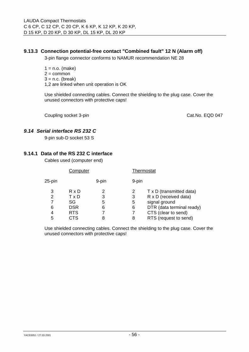
LAUDA Compact ThermostatsC 6 CP, C 12 CP, C 20 CP, K 6 KP, K 12 KP, K 20 KP,D 15 KP, D 20 KP, D 30 KP, DL 15 KP, DL 20 KP
YACE0051 / 27.03.2001 - 56 -
9.13.3 Connection potential-free contact "Combined fault" 12 N (Alarm off)3-pin flange connector conforms to NAMUR recommendation NE 28
1 = n.o. (make)2 = common3 = n.c. (break)1,2 are linked when unit operation is OK
Use shielded connecting cables. Connect the shielding to the plug case. Cover theunused connectors with protective caps!
Coupling socket 3-pin Cat.No. EQD 047
9.14 Serial interface RS 232 C9-pin sub-D socket 53 S
9.14.1 Data of the RS 232 C interfaceCables used (computer end)
Computer Thermostat
25-pin 9-pin 9-pin
3 R x D 2 2 T x D (transmitted data)2 T x D 3 3 R x D (received data)7 SG 5 5 signal ground6 DSR 6 6 DTR (data terminal ready)4 RTS 7 7 CTS (clear to send)5 CTS 8 8 RTS (request to send)
Use shielded connecting cables. Connect the shielding to the plug case. Cover theunused connectors with protective caps!
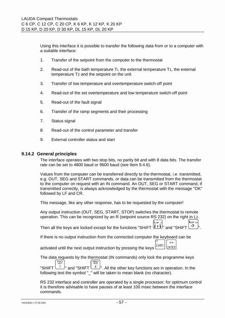
LAUDA Compact ThermostatsC 6 CP, C 12 CP, C 20 CP, K 6 KP, K 12 KP, K 20 KPD 15 KP, D 20 KP, D 30 KP, DL 15 KP, DL 20 KP
YACE0051 / 27.03.2001 - 57 -
Using this interface it is possible to transfer the following data from or to a computer witha suitable interface:
1. Transfer of the setpoint from the computer to the thermostat
2. Read-out of the bath temperature Ti, the external temperature T1, the external temperature T2 and the setpoint on the unit
3. Transfer of low temperature and overtemperature switch-off point
4. Read-out of the set overtemperature and low temperature switch-off point
5. Read-out of the fault signal
6. Transfer of the ramp segments and their processing
7. Status signal
8. Read-out of the control parameter and transfer
9. External controller status and start
9.14.2 General principlesThe interface operates with two stop bits, no parity bit and with 8 data bits. The transferrate can be set to 4800 baud or 9600 baud (see Item 9.4.6).
Values from the computer can be transferred directly to the thermostat, i.e. transmitted,e.g. OUT, SEG and START commands, or data can be transmitted from the thermostatto the computer on request with an IN command. An OUT, SEG or START command, iftransmitted correctly, is always acknowledged by the thermostat with the message "OK"followed by LF and CR.
This message, like any other response, has to be requested by the computer!
Any output instruction (OUT, SEG, START, STOP) switches the thermostat to remoteoperation. This can be recognized by an R (setpoint source RS 232) on the right in L2.
Then all the keys are locked except for the functions "SHIFT " and "SHIFT ".
If there is no output instruction from the connected computer the keyboard can be
activated until the next output instruction by pressing the keys .
The data requests by the thermostat (IN commands) only lock the programme keys
"SHIFT " and "SHIFT ". All the other key functions are in operation. In thefollowing text the symbol "_" will be taken to mean blank (no character).
RS 232 interface and controller are operated by a single processor; for optimum controlit is therefore advisable to have pauses of at least 100 msec between the interfacecommands.
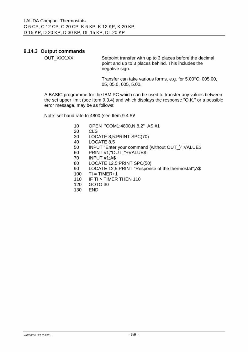
LAUDA Compact ThermostatsC 6 CP, C 12 CP, C 20 CP, K 6 KP, K 12 KP, K 20 KP,D 15 KP, D 20 KP, D 30 KP, DL 15 KP, DL 20 KP
YACE0051 / 27.03.2001 - 58 -
9.14.3 Output commandsOUT_XXX.XX Setpoint transfer with up to 3 places before the decimal
point and up to 3 places behind. This includes thenegative sign.
Transfer can take various forms, e.g. for 5.00°C: 005.00,05, 05.0, 005, 5.00.
A BASIC programme for the IBM PC which can be used to transfer any values betweenthe set upper limit (see Item 9.3.4) and which displays the response "O.K." or a possibleerror message, may be as follows:
Note: set baud rate to 4800 (see Item 9.4.5)!
10 OPEN "COM1:4800,N,8,2" AS #120 CLS30 LOCATE 8,5:PRINT SPC(70)40 LOCATE 8,550 INPUT "Enter your command (without OUT_)";VALUE$60 PRINT #1;"OUT_"+VALUE$70 INPUT #1;A$80 LOCATE 12,5:PRINT SPC(50)90 LOCATE 12,5:PRINT "Response of the thermostat";A$100 TI = TIMER+1110 IF TI > TIMER THEN 110120 GOTO 30130 END
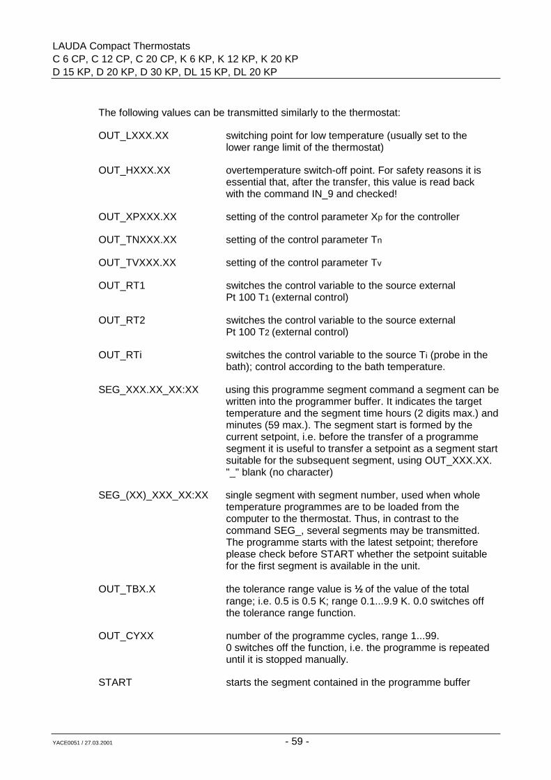
LAUDA Compact ThermostatsC 6 CP, C 12 CP, C 20 CP, K 6 KP, K 12 KP, K 20 KPD 15 KP, D 20 KP, D 30 KP, DL 15 KP, DL 20 KP
YACE0051 / 27.03.2001 - 59 -
The following values can be transmitted similarly to the thermostat:
OUT_LXXX.XX switching point for low temperature (usually set to thelower range limit of the thermostat)
OUT_HXXX.XX overtemperature switch-off point. For safety reasons it isessential that, after the transfer, this value is read backwith the command IN_9 and checked!
OUT_XPXXX.XX setting of the control parameter Xp for the controller
OUT_TNXXX.XX setting of the control parameter Tn
OUT_TVXXX.XX setting of the control parameter Tv
OUT_RT1 switches the control variable to the source externalPt 100 T1 (external control)
OUT_RT2 switches the control variable to the source externalPt 100 T2 (external control)
OUT_RTi switches the control variable to the source Ti (probe in thebath); control according to the bath temperature.
SEG_XXX.XX_XX:XX using this programme segment command a segment can bewritten into the programmer buffer. It indicates the target temperature and the segment time hours (2 digits max.) andminutes (59 max.). The segment start is formed by the current setpoint, i.e. before the transfer of a programme segment it is useful to transfer a setpoint as a segment startsuitable for the subsequent segment, using OUT_XXX.XX. "_" blank (no character)
SEG_(XX)_XXX_XX:XX single segment with segment number, used when whole temperature programmes are to be loaded from the computer to the thermostat. Thus, in contrast to the command SEG_, several segments may be transmitted. The programme starts with the latest setpoint; therefore please check before START whether the setpoint suitable for the first segment is available in the unit.
OUT_TBX.X the tolerance range value is ½ of the value of the total range; i.e. 0.5 is 0.5 K; range 0.1...9.9 K. 0.0 switches off the tolerance range function.
OUT_CYXX number of the programme cycles, range 1...99.0 switches off the function, i.e. the programme is repeateduntil it is stopped manually.
START starts the segment contained in the programme buffer
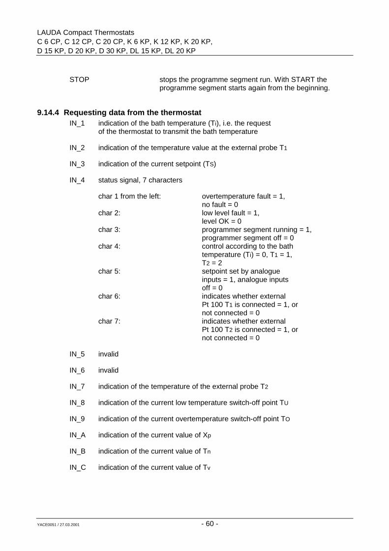
LAUDA Compact ThermostatsC 6 CP, C 12 CP, C 20 CP, K 6 KP, K 12 KP, K 20 KP,D 15 KP, D 20 KP, D 30 KP, DL 15 KP, DL 20 KP
YACE0051 / 27.03.2001 - 60 -
STOP stops the programme segment run. With START theprogramme segment starts again from the beginning.
9.14.4 Requesting data from the thermostatIN_1 indication of the bath temperature (Ti), i.e. the request
of the thermostat to transmit the bath temperature
IN_2 indication of the temperature value at the external probe T1
IN_3 indication of the current setpoint (TS)
IN_4 status signal, 7 characters
char 1 from the left: overtemperature fault = 1,no fault = 0
char 2: low level fault = 1,level OK = 0
char 3: programmer segment running = 1,programmer segment off = 0
char 4: control according to the bathtemperature (Ti) = 0, T1 = 1,T2 = 2
char 5: setpoint set by analogueinputs = 1, analogue inputsoff = 0
char 6: indicates whether externalPt 100 T1 is connected = 1, ornot connected = 0
char 7: indicates whether externalPt 100 T2 is connected = 1, ornot connected = 0
IN_5 invalid
IN_6 invalid
IN_7 indication of the temperature of the external probe T2
IN_8 indication of the current low temperature switch-off point TU
IN_9 indication of the current overtemperature switch-off point TO
IN_A indication of the current value of Xp
IN_B indication of the current value of Tn
IN_C indication of the current value of Tv
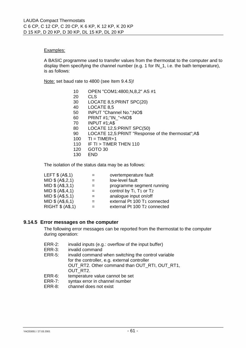
LAUDA Compact ThermostatsC 6 CP, C 12 CP, C 20 CP, K 6 KP, K 12 KP, K 20 KPD 15 KP, D 20 KP, D 30 KP, DL 15 KP, DL 20 KP
YACE0051 / 27.03.2001 - 61 -
Examples:
A BASIC programme used to transfer values from the thermostat to the computer and todisplay them specifying the channel number (e.g. 1 for IN_1, i.e. the bath temperature),is as follows:
Note: set baud rate to 4800 (see Item 9.4.5)!
10 OPEN "COM1:4800,N,8,2" AS #120 CLS30 LOCATE 8,5:PRINT SPC(20)40 LOCATE 8,550 INPUT "Channel No.";NO$60 PRINT #1;"IN_"+NO$70 INPUT #1;A$80 LOCATE 12,5:PRINT SPC(50)90 LOCATE 12,5:PRINT "Response of the thermostat";A$100 TI = TIMER+1110 IF TI > TIMER THEN 110120 GOTO 30130 END
The isolation of the status data may be as follows:
LEFT $ (A$,1) = overtemperature faultMID $ (A$,2,1) = low-level faultMID $ (A$,3,1) = programme segment runningMID $ (A$,4,1) = control by Ti, T1 or T2MID $ (A$,5,1) = analogue input on/offMID $ (A$,6,1) = external Pt 100 T1 connectedRIGHT $ (A$,1) = external Pt 100 T2 connected
9.14.5 Error messages on the computerThe following error messages can be reported from the thermostat to the computerduring operation:
ERR-2: invalid inputs (e.g.: overflow of the input buffer)ERR-3: invalid commandERR-5: invalid command when switching the control variable
for the controller, e.g. external controllerOUT_RT2. Other command than OUT_RTI, OUT_RT1,OUT_RT2.
ERR-6: temperature value cannot be setERR-7: syntax error in channel numberERR-8: channel does not exist
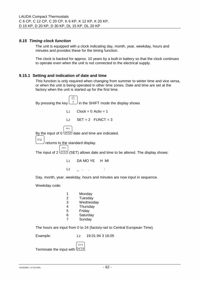
LAUDA Compact ThermostatsC 6 CP, C 12 CP, C 20 CP, K 6 KP, K 12 KP, K 20 KP,D 15 KP, D 20 KP, D 30 KP, DL 15 KP, DL 20 KP
YACE0051 / 27.03.2001 - 62 -
9.15 Timing clock functionThe unit is equipped with a clock indicating day, month, year, weekday, hours andminutes and provides these for the timing function.
The clock is backed for approx. 10 years by a built-in battery so that the clock continuesto operate even when the unit is not connected to the electrical supply.
9.15.1 Setting and indication of date and timeThis function is only required when changing from summer to winter time and vice versa,or when the unit is being operated in other time zones. Date and time are set at thefactory when the unit is started up for the first time.
By pressing the key in the SHIFT mode the display shows
L1 Clock = 0 Activ = 1
L2 SET = 2 FUNCT = 3
By the input of 0 date and time are indicated.
returns to the standard display.
The input of 2 (SET) allows date and time to be altered. The display shows:
L1 DA MO YE H MI
L2 _ . . :
Day, month, year, weekday, hours and minutes are now input in sequence.
Weekday code:
1 Monday2 Tuesday3 Wednesday4 Thursday5 Friday6 Saturday7 Sunday
The hours are input from 0 to 24 (factory-set to Central European Time).
Example: L2 19.01.94 3 16:05
Terminate the input with .
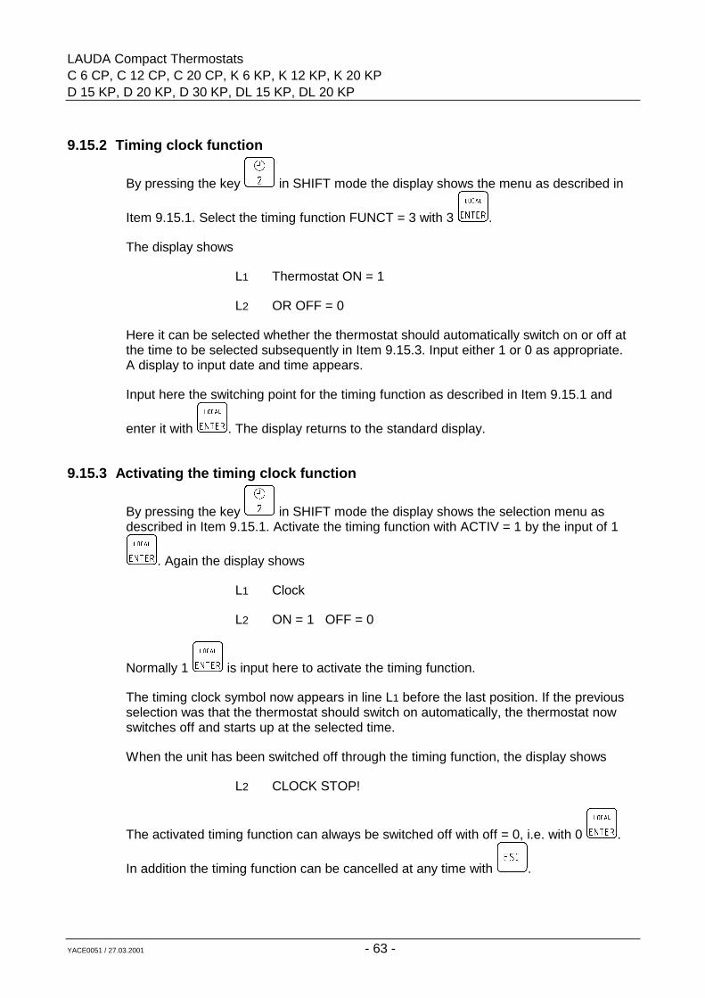
LAUDA Compact ThermostatsC 6 CP, C 12 CP, C 20 CP, K 6 KP, K 12 KP, K 20 KPD 15 KP, D 20 KP, D 30 KP, DL 15 KP, DL 20 KP
YACE0051 / 27.03.2001 - 63 -
9.15.2 Timing clock function
By pressing the key in SHIFT mode the display shows the menu as described in
Item 9.15.1. Select the timing function FUNCT = 3 with 3 .
The display shows
L1 Thermostat ON = 1
L2 OR OFF = 0
Here it can be selected whether the thermostat should automatically switch on or off atthe time to be selected subsequently in Item 9.15.3. Input either 1 or 0 as appropriate.A display to input date and time appears.
Input here the switching point for the timing function as described in Item 9.15.1 and
enter it with . The display returns to the standard display.
9.15.3 Activating the timing clock function
By pressing the key in SHIFT mode the display shows the selection menu asdescribed in Item 9.15.1. Activate the timing function with ACTIV = 1 by the input of 1
. Again the display shows
L1 Clock
L2 ON = 1 OFF = 0
Normally 1 is input here to activate the timing function.
The timing clock symbol now appears in line L1 before the last position. If the previousselection was that the thermostat should switch on automatically, the thermostat nowswitches off and starts up at the selected time.
When the unit has been switched off through the timing function, the display shows
L2 CLOCK STOP!
The activated timing function can always be switched off with off = 0, i.e. with 0 .
In addition the timing function can be cancelled at any time with .
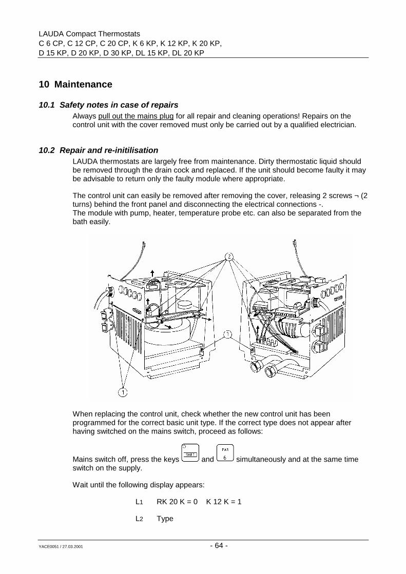
LAUDA Compact ThermostatsC 6 CP, C 12 CP, C 20 CP, K 6 KP, K 12 KP, K 20 KP,D 15 KP, D 20 KP, D 30 KP, DL 15 KP, DL 20 KP
YACE0051 / 27.03.2001 - 64 -
10 Maintenance
10.1 Safety notes in case of repairsAlways pull out the mains plug for all repair and cleaning operations! Repairs on thecontrol unit with the cover removed must only be carried out by a qualified electrician.
10.2 Repair and re-initilisationLAUDA thermostats are largely free from maintenance. Dirty thermostatic liquid shouldbe removed through the drain cock and replaced. If the unit should become faulty it maybe advisable to return only the faulty module where appropriate.
The control unit can easily be removed after removing the cover, releasing 2 screws ¬ (2turns) behind the front panel and disconnecting the electrical connections -.The module with pump, heater, temperature probe etc. can also be separated from thebath easily.
When replacing the control unit, check whether the new control unit has beenprogrammed for the correct basic unit type. If the correct type does not appear afterhaving switched on the mains switch, proceed as follows:
Mains switch off, press the keys and simultaneously and at the same timeswitch on the supply.
Wait until the following display appears:
L1 RK 20 K = 0 K 12 K = 1
L2 Type
LAUDA Compact ThermostatsC 6 CP, C 12 CP, C 20 CP, K 6 KP, K 12 KP, K 20 KPD 15 KP, D 20 KP, D 30 KP, DL 15 KP, DL 20 KP
YACE0051 / 27.03.2001 - 65 -
Release the keys and , and go through the menu with the key until the
required type appears. Input the code number and enter with .
The type designations are shown abbreviated, e.g. C 6 C instead of C 6 CP.
There is no provision for a fuse for the complete unit since the necessary 16A fusecorresponds to the mains fuse usually provided at the location. The control circuit of theunit has a separate fuse; a fuse 5 x 20 F4A is located in the control unit. This isaccessible after removing the cover. When the fuse has blown the green lamp in themains switch does not light up.
10.3 CleaningThe unit can be cleaned using a cloth moistened with water with the addition of a fewdrops of (domestic) detergent. No water must find its way into the control unit.
The user is responsible for any necessary decontamination if dangerous materials havebeen spilled on or inside the unit. This applies in particular if the unit is removed for adifferent use, for repair, storage etc.
The method of cleaning or decontamination is determined by the expertise of the userhimself. If the user has any doubts on whether this may damage the unit he has tocontact the manufacturer.
10.4 Spares orderingWhen ordering spares please specify the equipment type and number on the label. Thisavoids queries and prevents the supply of wrong goods!
We shall always be happy to deal with queries, suggestions and complaints.
LAUDA DR. R. WOBSERGMBH & CO. KG
Postfach 125197912 Lauda-KönigshofenTel: (+49) (0) 9343/ 503-0
Fax: (+49) (0) 9343/ 503-222E-mail info @@@@ lauda.de
Internet http://www.lauda.de
LAUDA Compact ThermostatsC 6 CP, C 12 CP, C 20 CP, K 6 KP, K 12 KP, K 20 KP,D 15 KP, D 20 KP, D 30 KP, DL 15 KP, DL 20 KP
YACE0051 / 27.03.2001 - 66 -
11 AccessoriesLAUDA Compact Temperature Thermostats C-P and K-P
LAUDA through-flow chillersFor cooling thermostats, in particular DLK 10 Cat. No. LFD 105at operating temperatures below DLK 25 Cat. No. LFD 106the working temperature range DLK 45 Cat. No. LFD 107
Racks in stainless steelfor test tubes, centrifuge tubes etc.
Bath C 12 up to 2 racksBath C 20 up to 4 racksRD 13 for 56 tubes 10 - 13 dia., 80 mm immersion Cat. No. UG 066RD 18/1 for 33 tubes 14 - 18 dia., 80 mm immersion Cat. No. UG 067RD 18/2 for 33 tubes 14 - 18 dia., 110 mm immersion Cat. No. UG 068RD 30 for 14 tubes 24 - 30 dia., 110 mm immersion Cat. No. UG 069
Bath K 20 up to 2 racksRE 13 for 56 tubes 10 - 13 dia., 80 mm immersion Cat. No. UG 070RE 18/1 for 33 tubes 14 - 18 dia., 80 mm immersion Cat. No. UG 071RE 18/2 for 33 tubes 14 - 18 dia., 110 mm immersion Cat. No. UG 072RE 30 for 14 tubes 24 - 30 dia., 110 mm immersion Cat. No. UG 073
Bath C 6 1 rackRF 18/1 for 20 tubes 14 - 18 dia., 80 mm immersion Cat. No. UG 074RF 18/2 for 20 tubes 14 - 18 dia., 110 mm immersion Cat. No. UG 075
Bath K 6 1 rackRG 18/1 for 20 tubes 14 - 18 dia., 80 mm immersion Cat. No. UG 076RK 18/2 for 20 tubes 14 - 18 dia., 110 mm immersion Cat. No. UG 077
Details of other racks on request.
Rising platform for retrofittingsize 250x160 mm, with continuous height adjustment Cat. No. LCZ 012suitable for:
Bath C 12 (1 platform)Bath C 20 (2 platforms)Bath K 20 (1 platform)
Gable cover, stainless steel for C 20 Cat. No. LCZ 011
Level controller Cat. No. LPZ 901for thermostating an open external bathusing pressure/suction pump
Non-return fitting Cat. No. UD 125for automatic venting of the connecting hoseswhen thermostating an open external bath
LAUDA Compact ThermostatsC 6 CP, C 12 CP, C 20 CP, K 6 KP, K 12 KP, K 20 KPD 15 KP, D 20 KP, D 30 KP, DL 15 KP, DL 20 KP
YACE0051 / 27.03.2001 - 67 -
Cover plates for clear-view thermostats
UD 15 K for 3 manual measuring stands D 15 KP/ Cat. No. LTZ 017DL 15 KP
UD 20 K for 5 manual measuring stands D 20 KP/ Cat. No. LTZ 019DL 20 KP
UD 30 K for 9 manual measuring stands D 30 KP Cat. No. LTZ 021
UD 15 V for 2 automatic measuring stands D 15 KP/ Cat. No. LTZ 018DL 15 KP
UD 20 V for 4 automatic measuring stands D 20 KP/ Cat. No. LTZ 020DL 20 KP
UD 30 V for 6 automatic measuring stands D 30 KP Cat. No. LTZ 022
UD 15 V/K for 2 manual measuring stands D 15 KP/ Cat. No. LTZ 030and 1 automatic measuring stand DL 15 KPUD 20 V/K for 3 manual measuring stands D 20 KP/ Cat. No. LTZ 031and 3 automatic measuring stands DL 20 KP
Cover plates made of plastic,particularly for low temperatures
UDL 15 K for 3 manual measuring stands DL 15 KP Cat. No. LTZ 041UDL 15 V for 2 automatic measuring stands DL 15 KP Cat. No. LTZ 042UDL 20 K for 5 manual measuring stands DL 20 KP Cat. No. LTZ 043UDL 20 V for 4 automatic measuring stands DL 20 KP Cat. No. LTZ 044
Atherman illuminators ALspecial large-area non-dazzling illuminatorsfree from thermal radiationAL 15 D 15 KP/ Cat. No. LTZ 001
DL 15 KPAL 20 D 20 KP/ Cat. No. LTZ 002
DL 20 KPAL 30 D 30 KP Cat. No. LTZ 003
Remote operation FBC Cat. No. LCZ 960without cable setThe electronic control unit is placed separatelyfrom the unit and linked to it by cable.
Cable set for FBC length 5 m Cat. No. UK 235
Cable set for FBC length as specified Cat. No. UK 238
Nipplesfor pump connections13 mm dia., 10 mm int. dia. Cat. No. HKO 02611 mm dia., 7 mm int. dia. Cat. No. HKO 025
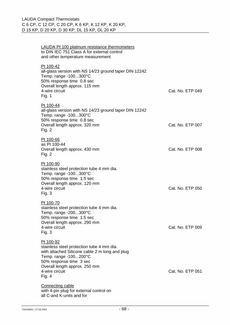
LAUDA Compact ThermostatsC 6 CP, C 12 CP, C 20 CP, K 6 KP, K 12 KP, K 20 KP,D 15 KP, D 20 KP, D 30 KP, DL 15 KP, DL 20 KP
YACE0051 / 27.03.2001 - 68 -
LAUDA Pt 100 platinum resistance thermometersto DIN IEC 751 Class A for external controland other temperature measurement
Pt 100-42all-glass version with NS 14/23 ground taper DIN 12242Temp. range -100...300°C50% response time 0.8 secOverall length approx. 115 mm4-wire circuit Cat. No. ETP 049Fig. 1
Pt 100-44all-glass version with NS 14/23 ground taper DIN 12242Temp. range -100...300°C50% response time 0.8 secOverall length approx. 320 mm Cat. No. ETP 007Fig. 2
Pt 100-66as Pt 100-44Overall length approx. 430 mm Cat. No. ETP 008Fig. 2
Pt 100-90stainless steel protection tube 4 mm dia.Temp. range -100...300°C50% response time 1.5 secOverall length approx. 120 mm4-wire circuit Cat. No. ETP 050Fig. 3
Pt 100-70stainless steel protection tube 4 mm dia.Temp. range -200...300°C50% response time 1.5 secOverall length approx. 290 mm4-wire circuit Cat. No. ETP 009Fig. 3
Pt 100-92stainless steel protection tube 4 mm dia.with attached Silicone cable 2 m long and plugTemp. range -100...200°C50% response time 3 secOverall length approx. 250 mm4-wire circuit Cat. No. ETP 051Fig. 4
Connecting cablewith 4-pin plug for external control onall C-and K-units and for
LAUDA Compact ThermostatsC 6 CP, C 12 CP, C 20 CP, K 6 KP, K 12 KP, K 20 KPD 15 KP, D 20 KP, D 30 KP, DL 15 KP, DL 20 KP
YACE0051 / 27.03.2001 - 69 -
digital thermometer for Pt 100-44 andPt 100-66 1.5 m Cat. No. UK 048length as specified Cat. No. UK 213
for Pt 100-42, Pt 100-70, Pt 100-90 1.5 m Cat. No. UK 047length as specified Cat. No. UK 212
Screw clamp fittingstainless steel, with Teflon pressure ringfor Pt 100 resistance thermometer 4 mm dia. Cat. No. HX 078Fig 5
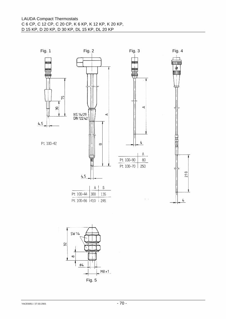
LAUDA Compact ThermostatsC 6 CP, C 12 CP, C 20 CP, K 6 KP, K 12 KP, K 20 KP,D 15 KP, D 20 KP, D 30 KP, DL 15 KP, DL 20 KP
YACE0051 / 27.03.2001 - 70 -
Fig. 1 Fig. 2 Fig. 3 Fig. 4
Fig. 5
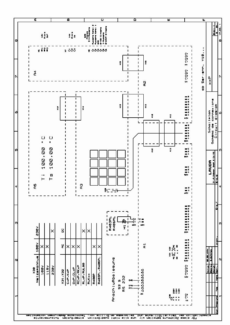

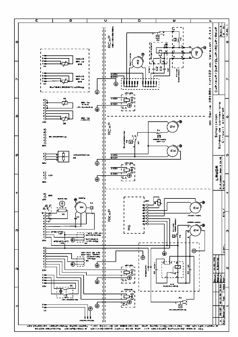

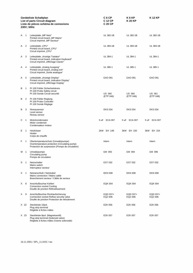
Geräteliste Schaltplan C 6 CP K 6 KP K 12 KPList of parts Circuit diagram C 12 CP K 20 KPListe de pièces schéma de connexions C 20 CP230V; 50Hz
A 1 Leiterplatte „MP Netz“ UL 382-1B UL 382-1B UL 382-1BPrinted circuit board „MP-Mains“Circuit imprimé „MP-Secteur“
A 2 Leiterplatte „CPU“ UL 383-1B UL 383-1B UL 383-1BPrinted circuit board „CPU“Circuit imprimé „CPU“
A 3 Leiterplatte „Anzeige Tastatur“ UL 384-1 UL 384-1 UL 384-1Printed circuit board „Indication Keyboard“Circuit imprimé „Affichage Clavier“
A 4 Leiterplatte „Analog Ausgang“ UL 385-1 UL 385-1 UL 385-1Printed circuit board „Analog exit“Circuit imprimé „Sortie analogue“
A 5 Leiterplatte „Anzeige Display“ EAO 091 EAO 091 EAO 091Printed circuit board „Indication Display“Circuit imprimé „Affichage Dsiplay“
B 1 Pt 100 Fühler SicherheitskreisPt 100 Probe Safety circuitPt 100 Sonde Circuit securité US 060 US 060 US 061
(ETP 046) (ETP 046) (ETP 048)B 2 Pt 100 Fühler Reglung
Pt 100 Probe ControllerPt 100 Sonde Réglage
B 3 Niveausensor EKS 034 EKS 034 EKS 034Level sensorNiveau sensor
C 1 Motorkondensator 5 uF ECA 007 5 uF ECA 007 5 uF ECA 007Motor condenser Condensateur moteur
E 1 Heizkörper 2kW EH 148 3kW EH 150 3kW EH 154HeaterCorps de chauffe
F 1 Übertemperaturschutz (Umwälzpumpe) Intern Intern InternOvertemperature protection (Circulating pump)Protection de surpression (Pompe de circulation)
M 1 Umwälzpumpe EM 093 EM 094 EM 096Circulating pumpPompe de circulation
S 1 Netzschalter EST 032 EST 032 EST 032Mains switchInterrupteur secteur
X 1 Netzanschluß / Netzkabel EKN 008 EKN 008 EKN 008Mains connection / Mains cableBranchement secteur / Câble de secteur
X 8 Anschlußbuchse Kühlen EQK 004 EQK 004 EQK 004Connection socket CoolingDouille de jonction Réfroidissement
X 9 Anschlußbuchse Rücklaufsicherung EQD 037+ EQD 037+ EQD 037+Connection socket Reflow security valve EQZ 006 EQZ 006 EQZ 006Douille de jonction Protection de refoulement
X 22 Steckleiste 10pol. EZK 056 EZK 056 EZK 056Plug strip terminalRéglette à fiches mâles
X 23 Steckleiste 8pol. (Magnetventil) EZK 057 EZK 057 EZK 057Plug strip terminal (Solenoid valve)Réglette à fiches mâles (Vanne solenoide)
16.11.2001 / SPL_11.DOC / wo

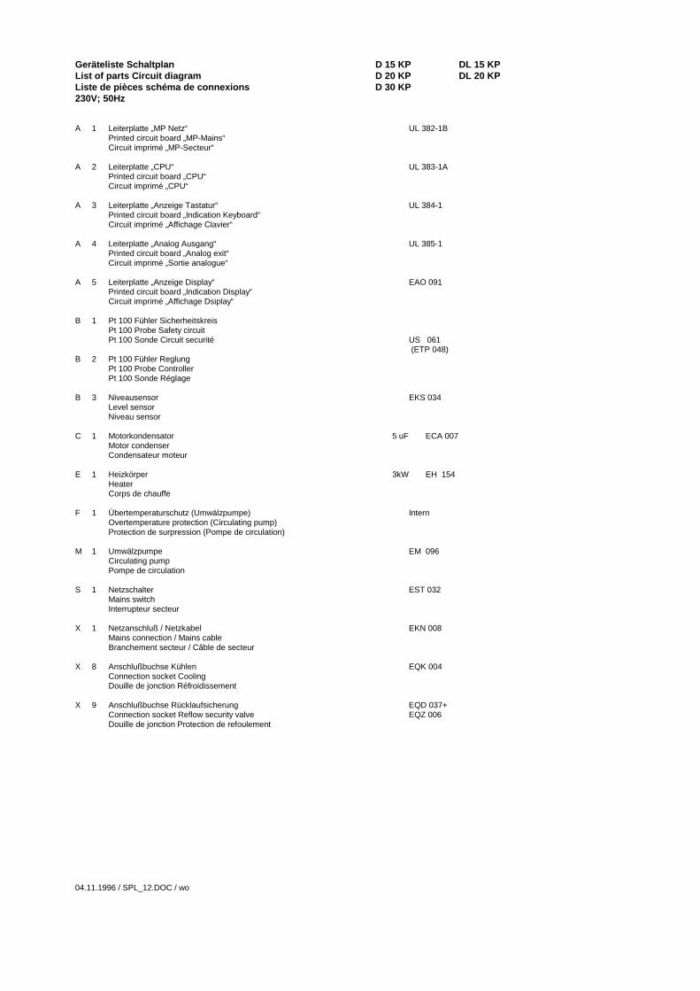
Geräteliste Schaltplan D 15 KP DL 15 KPList of parts Circuit diagram D 20 KP DL 20 KPListe de pièces schéma de connexions D 30 KP230V; 50Hz
A 1 Leiterplatte „MP Netz“ UL 382-1BPrinted circuit board „MP-Mains“Circuit imprimé „MP-Secteur“
A 2 Leiterplatte „CPU“ UL 383-1APrinted circuit board „CPU“Circuit imprimé „CPU“
A 3 Leiterplatte „Anzeige Tastatur“ UL 384-1Printed circuit board „Indication Keyboard“Circuit imprimé „Affichage Clavier“
A 4 Leiterplatte „Analog Ausgang“ UL 385-1Printed circuit board „Analog exit“Circuit imprimé „Sortie analogue“
A 5 Leiterplatte „Anzeige Display“ EAO 091Printed circuit board „Indication Display“Circuit imprimé „Affichage Dsiplay“
B 1 Pt 100 Fühler SicherheitskreisPt 100 Probe Safety circuitPt 100 Sonde Circuit securité US 061
(ETP 048)B 2 Pt 100 Fühler Reglung
Pt 100 Probe ControllerPt 100 Sonde Réglage
B 3 Niveausensor EKS 034Level sensorNiveau sensor
C 1 Motorkondensator 5 uF ECA 007Motor condenser Condensateur moteur
E 1 Heizkörper 3kW EH 154HeaterCorps de chauffe
F 1 Übertemperaturschutz (Umwälzpumpe) InternOvertemperature protection (Circulating pump)Protection de surpression (Pompe de circulation)
M 1 Umwälzpumpe EM 096Circulating pumpPompe de circulation
S 1 Netzschalter EST 032Mains switchInterrupteur secteur
X 1 Netzanschluß / Netzkabel EKN 008Mains connection / Mains cableBranchement secteur / Câble de secteur
X 8 Anschlußbuchse Kühlen EQK 004Connection socket CoolingDouille de jonction Réfroidissement
X 9 Anschlußbuchse Rücklaufsicherung EQD 037+Connection socket Reflow security valve EQZ 006Douille de jonction Protection de refoulement
04.11.1996 / SPL_12.DOC / wo

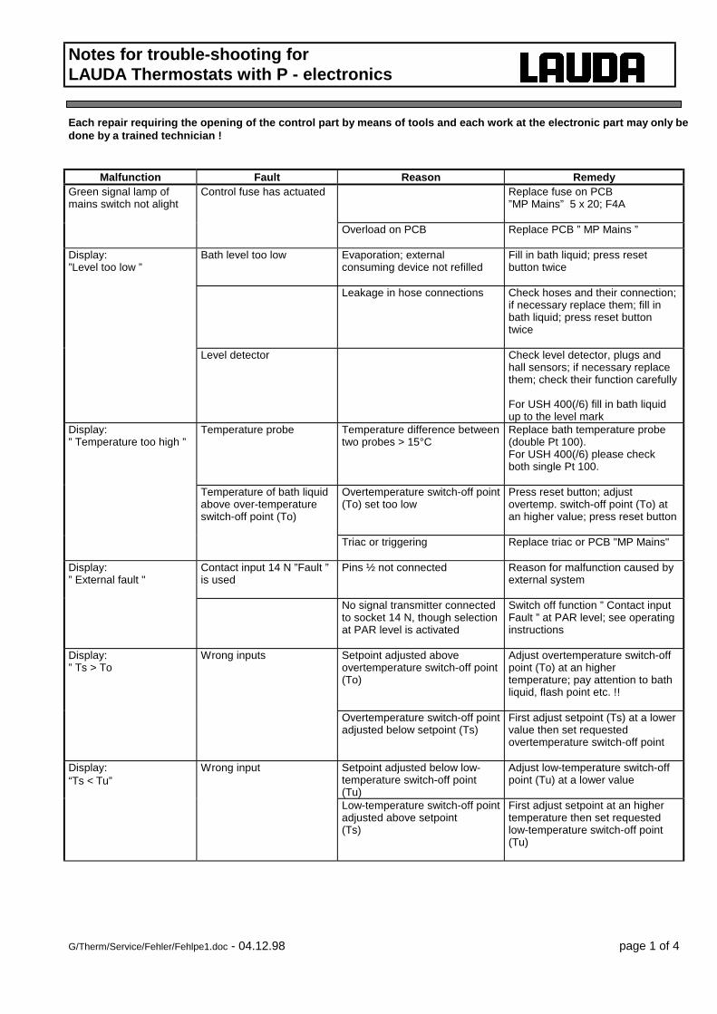
Notes for trouble-shooting forLAUDA Thermostats with P - electronics
G/Therm/Service/Fehler/Fehlpe1.doc - 04.12.98 page 1 of 4
Each repair requiring the opening of the control part by means of tools and each work at the electronic part may only bedone by a trained technician !
Malfunction Fault Reason RemedyGreen signal lamp ofmains switch not alight
Control fuse has actuated Replace fuse on PCB”MP Mains” 5 x 20; F4A
Overload on PCB Replace PCB ” MP Mains ”
Display:”Level too low ”
Bath level too low Evaporation; externalconsuming device not refilled
Fill in bath liquid; press resetbutton twice
Leakage in hose connections Check hoses and their connection;if necessary replace them; fill inbath liquid; press reset buttontwice
Level detector Check level detector, plugs andhall sensors; if necessary replacethem; check their function carefully
For USH 400(/6) fill in bath liquidup to the level mark
Display:” Temperature too high ”
Temperature probe Temperature difference betweentwo probes > 15°C
Replace bath temperature probe(double Pt 100).For USH 400(/6) please checkboth single Pt 100.
Temperature of bath liquidabove over-temperatureswitch-off point (To)
Overtemperature switch-off point(To) set too low
Press reset button; adjustovertemp. switch-off point (To) atan higher value; press reset button
Triac or triggering Replace triac or PCB "MP Mains"
Display:” External fault "
Contact input 14 N ”Fault ”is used
Pins ½ not connected Reason for malfunction caused byexternal system
No signal transmitter connectedto socket 14 N, though selectionat PAR level is activated
Switch off function ” Contact inputFault ” at PAR level; see operatinginstructions
Display:” Ts > To
Wrong inputs Setpoint adjusted aboveovertemperature switch-off point(To)
Adjust overtemperature switch-offpoint (To) at an highertemperature; pay attention to bathliquid, flash point etc. !!
Overtemperature switch-off pointadjusted below setpoint (Ts)
First adjust setpoint (Ts) at a lowervalue then set requestedovertemperature switch-off point
Display:“Ts < Tu”
Wrong input Setpoint adjusted below low-temperature switch-off point(Tu)
Adjust low-temperature switch-offpoint (Tu) at a lower value
Low-temperature switch-off pointadjusted above setpoint(Ts)
First adjust setpoint at an highertemperature then set requestedlow-temperature switch-off point(Tu)

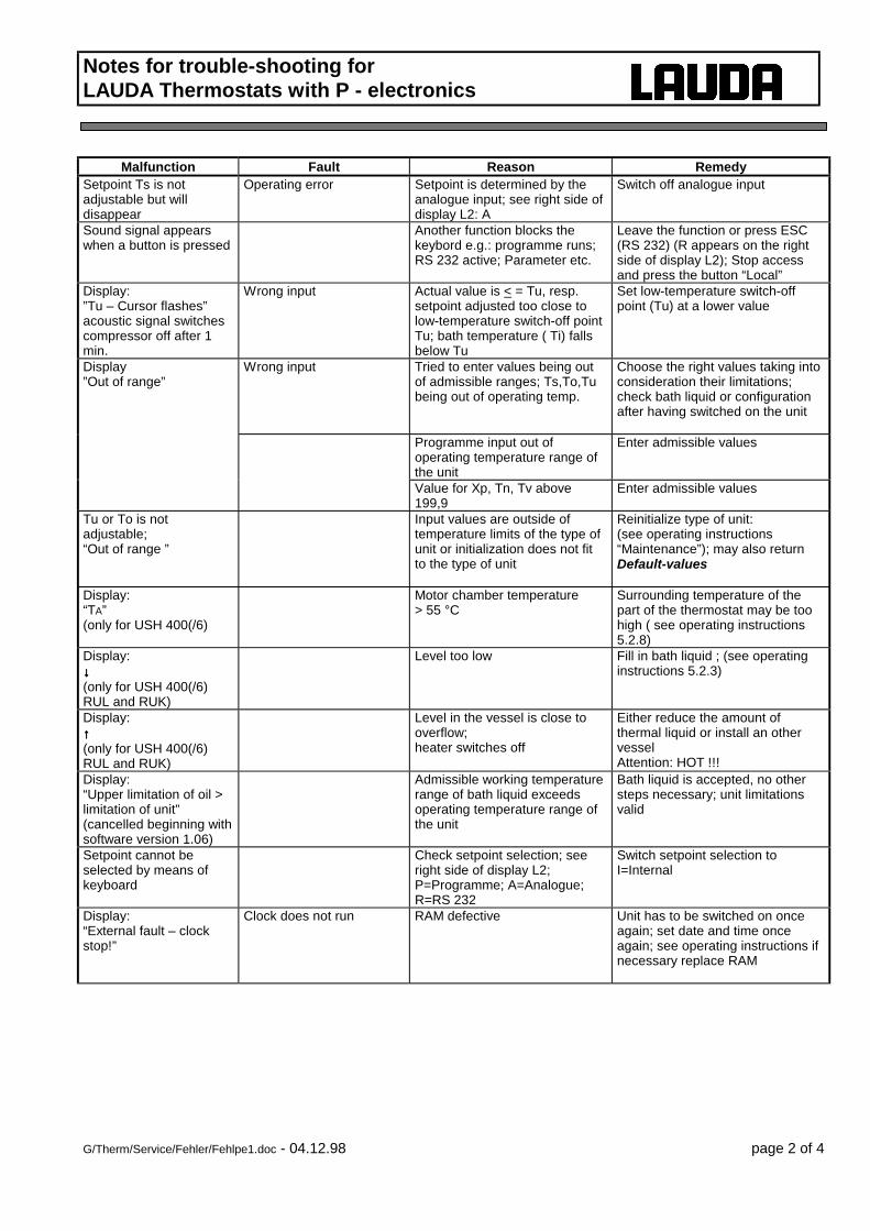
Notes for trouble-shooting forLAUDA Thermostats with P - electronics
G/Therm/Service/Fehler/Fehlpe1.doc - 04.12.98 page 2 of 4
Malfunction Fault Reason RemedySetpoint Ts is notadjustable but willdisappear
Operating error Setpoint is determined by theanalogue input; see right side ofdisplay L2: A
Switch off analogue input
Sound signal appearswhen a button is pressed
Another function blocks thekeybord e.g.: programme runs;RS 232 active; Parameter etc.
Leave the function or press ESC(RS 232) (R appears on the rightside of display L2); Stop accessand press the button “Local”
Display:”Tu – Cursor flashes”acoustic signal switchescompressor off after 1min.
Wrong input Actual value is < = Tu, resp.setpoint adjusted too close tolow-temperature switch-off pointTu; bath temperature ( Ti) fallsbelow Tu
Set low-temperature switch-offpoint (Tu) at a lower value
Display”Out of range”
Wrong input Tried to enter values being outof admissible ranges; Ts,To,Tubeing out of operating temp.
Choose the right values taking intoconsideration their limitations;check bath liquid or configurationafter having switched on the unit
Programme input out ofoperating temperature range ofthe unit
Enter admissible values
Value for Xp, Tn, Tv above199,9
Enter admissible values
Tu or To is notadjustable;“Out of range ”
Input values are outside oftemperature limits of the type ofunit or initialization does not fitto the type of unit
Reinitialize type of unit:(see operating instructions“Maintenance”); may also returnDefault-values
Display:“TA”(only for USH 400(/6)
Motor chamber temperature> 55 °C
Surrounding temperature of thepart of the thermostat may be toohigh ( see operating instructions5.2.8)
Display:↓↓↓↓(only for USH 400(/6)RUL and RUK)
Level too low Fill in bath liquid ; (see operatinginstructions 5.2.3)
Display:↑↑↑↑(only for USH 400(/6)RUL and RUK)
Level in the vessel is close tooverflow;heater switches off
Either reduce the amount ofthermal liquid or install an othervesselAttention: HOT !!!
Display:“Upper limitation of oil >limitation of unit”(cancelled beginning withsoftware version 1.06)
Admissible working temperaturerange of bath liquid exceedsoperating temperature range ofthe unit
Bath liquid is accepted, no othersteps necessary; unit limitationsvalid
Setpoint cannot beselected by means ofkeyboard
Check setpoint selection; seeright side of display L2;P=Programme; A=Analogue;R=RS 232
Switch setpoint selection toI=Internal
Display:“External fault – clockstop!”
Clock does not run RAM defective Unit has to be switched on onceagain; set date and time onceagain; see operating instructions ifnecessary replace RAM

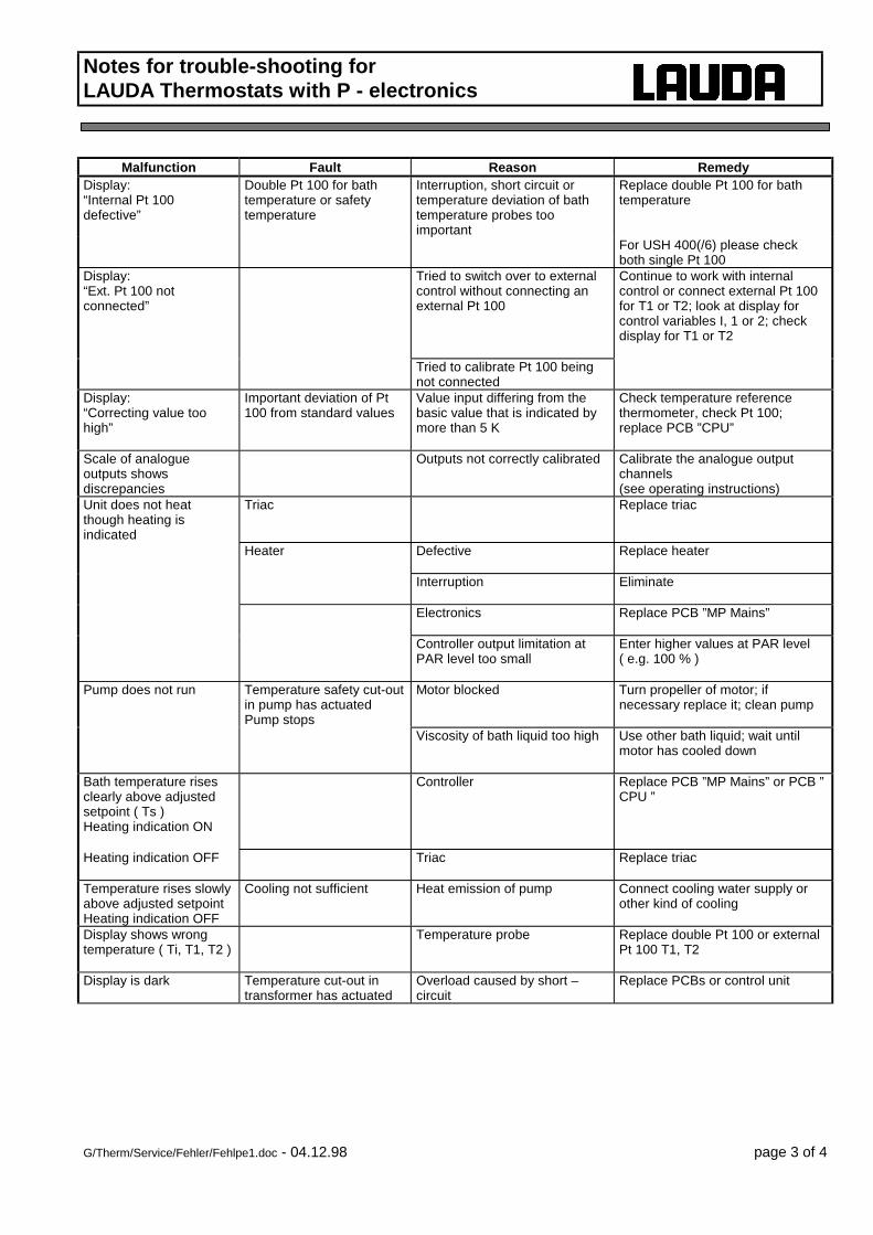
Notes for trouble-shooting forLAUDA Thermostats with P - electronics
G/Therm/Service/Fehler/Fehlpe1.doc - 04.12.98 page 3 of 4
Malfunction Fault Reason RemedyDisplay:“Internal Pt 100defective”
Double Pt 100 for bathtemperature or safetytemperature
Interruption, short circuit ortemperature deviation of bathtemperature probes tooimportant
Replace double Pt 100 for bathtemperature
For USH 400(/6) please checkboth single Pt 100
Display:“Ext. Pt 100 notconnected”
Tried to switch over to externalcontrol without connecting anexternal Pt 100
Continue to work with internalcontrol or connect external Pt 100for T1 or T2; look at display forcontrol variables I, 1 or 2; checkdisplay for T1 or T2
Tried to calibrate Pt 100 beingnot connected
Display:“Correcting value toohigh”
Important deviation of Pt100 from standard values
Value input differing from thebasic value that is indicated bymore than 5 K
Check temperature referencethermometer, check Pt 100;replace PCB ”CPU”
Scale of analogueoutputs showsdiscrepancies
Outputs not correctly calibrated Calibrate the analogue outputchannels(see operating instructions)
Unit does not heatthough heating isindicated
Triac Replace triac
Heater Defective Replace heater
Interruption Eliminate
Electronics Replace PCB ”MP Mains”
Controller output limitation atPAR level too small
Enter higher values at PAR level( e.g. 100 % )
Pump does not run Temperature safety cut-outin pump has actuatedPump stops
Motor blocked Turn propeller of motor; ifnecessary replace it; clean pump
Viscosity of bath liquid too high Use other bath liquid; wait untilmotor has cooled down
Bath temperature risesclearly above adjustedsetpoint ( Ts )Heating indication ON
Controller Replace PCB ”MP Mains” or PCB ”CPU ”
Heating indication OFF Triac Replace triac
Temperature rises slowlyabove adjusted setpointHeating indication OFF
Cooling not sufficient Heat emission of pump Connect cooling water supply orother kind of cooling
Display shows wrongtemperature ( Ti, T1, T2 )
Temperature probe Replace double Pt 100 or externalPt 100 T1, T2
Display is dark Temperature cut-out intransformer has actuated
Overload caused by short –circuit
Replace PCBs or control unit

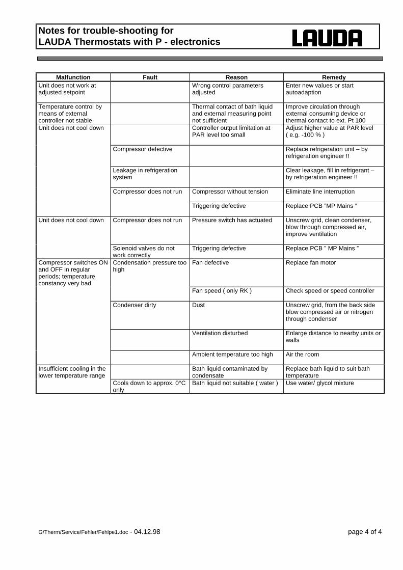
Notes for trouble-shooting forLAUDA Thermostats with P - electronics
G/Therm/Service/Fehler/Fehlpe1.doc - 04.12.98 page 4 of 4
Malfunction Fault Reason RemedyUnit does not work atadjusted setpoint
Wrong control parametersadjusted
Enter new values or startautoadaption
Temperature control bymeans of externalcontroller not stable
Thermal contact of bath liquidand external measuring pointnot sufficient
Improve circulation throughexternal consuming device orthermal contact to ext. Pt 100
Unit does not cool down Controller output limitation atPAR level too small
Adjust higher value at PAR level( e.g. -100 % )
Compressor defective Replace refrigeration unit – byrefrigeration engineer !!
Leakage in refrigerationsystem
Clear leakage, fill in refrigerant –by refrigeration engineer !!
Compressor does not run Compressor without tension Eliminate line interruption
Triggering defective Replace PCB ”MP Mains ”
Unit does not cool down Compressor does not run Pressure switch has actuated Unscrew grid, clean condenser,blow through compressed air,improve ventilation
Solenoid valves do notwork correctly
Triggering defective Replace PCB ” MP Mains ”
Compressor switches ONand OFF in regularperiods; temperatureconstancy very bad
Condensation pressure toohigh
Fan defective Replace fan motor
Fan speed ( only RK ) Check speed or speed controller
Condenser dirty Dust Unscrew grid, from the back sideblow compressed air or nitrogenthrough condenser
Ventilation disturbed Enlarge distance to nearby units orwalls
Ambient temperature too high Air the room
Insufficient cooling in thelower temperature range
Bath liquid contaminated bycondensate
Replace bath liquid to suit bathtemperature
Cools down to approx. 0°Conly
Bath liquid not suitable ( water ) Use water/ glycol mixture

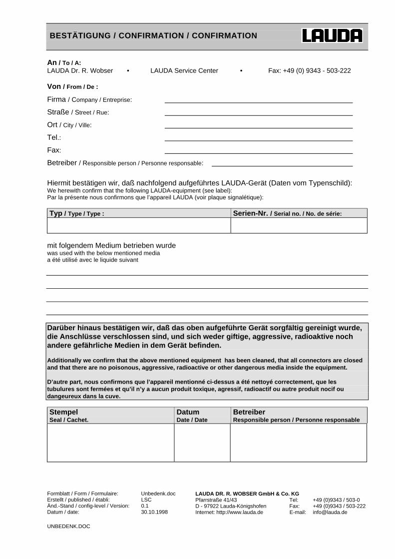
BESTÄTIGUNG / CONFIRMATION / CONFIRMATION
Formblatt / Form / Formulaire: Unbedenk.docErstellt / published / établi: LSCÄnd.-Stand / config-level / Version: 0.1Datum / date: 30.10.1998
LAUDA DR. R. WOBSER GmbH & Co. KGPfarrstraße 41/43 Tel: +49 (0)9343 / 503-0D - 97922 Lauda-Königshofen Fax: +49 (0)9343 / 503-222Internet: http://www.lauda.de E-mail: [email protected]
UNBEDENK.DOC
An / To / A:LAUDA Dr. R. Wobser • LAUDA Service Center • Fax: +49 (0) 9343 - 503-222
Von / From / De :
Firma / Company / Entreprise:
Straße / Street / Rue:
Ort / City / Ville:
Tel.:
Fax:
Betreiber / Responsible person / Personne responsable:
Hiermit bestätigen wir, daß nachfolgend aufgeführtes LAUDA-Gerät (Daten vom Typenschild):We herewith confirm that the following LAUDA-equipment (see label):Par la présente nous confirmons que l’appareil LAUDA (voir plaque signalétique):
Typ / Type / Type : Serien-Nr. / Serial no. / No. de série:
mit folgendem Medium betrieben wurdewas used with the below mentioned mediaa été utilisé avec le liquide suivant
Darüber hinaus bestätigen wir, daß das oben aufgeführte Gerät sorgfältig gereinigt wurde,die Anschlüsse verschlossen sind, und sich weder giftige, aggressive, radioaktive nochandere gefährliche Medien in dem Gerät befinden.
Additionally we confirm that the above mentioned equipment has been cleaned, that all connectors are closedand that there are no poisonous, aggressive, radioactive or other dangerous media inside the equipment.
D’autre part, nous confirmons que l’appareil mentionné ci-dessus a été nettoyé correctement, que lestubulures sont fermées et qu’il n’y a aucun produit toxique, agressif, radioactif ou autre produit nocif oudangeureux dans la cuve.
StempelSeal / Cachet.
DatumDate / Date
BetreiberResponsible person / Personne responsable