
BRIDGET System Architecture and Interfaces Version...
40
BRIDGET System Architecture and Interfaces Version B Period Covered 2015/12/01–2016/01/31 Project ref. no. FP7-ICT-610691 Project acronym BRIDGET Start date of project (duration) 1 November, 2013 (36 months) Document due Date: 31 January 2016 Actual date of delivery 29 January 2016 Leader of this document Diego Gibellino (Telecom Italia) Reply to [email protected] Document status Final
-
Upload
nguyenkien -
Category
Documents
-
view
231 -
download
0
Transcript of BRIDGET System Architecture and Interfaces Version...

BRIDGET System Architecture and Interfaces Version B
Period Covered 2015/12/01–2016/01/31
Project ref. no. FP7-ICT-610691
Project acronym BRIDGET
Start date of project (duration) 1 November, 2013 (36 months)
Document due Date: 31 January 2016
Actual date of delivery 29 January 2016
Leader of this document Diego Gibellino (Telecom Italia)
Reply to [email protected]
Document status Final

FP7-610691 BRIDGET System Architecture and Interfaces Version B
D3.3_SystemArchitectureandInterfaces.DOCX 2/40
Deliverable Identification Sheet
Project ref. no. FP7-ICT-610691
Project acronym BRIDGET
Project full title BRIDging the Gap for Enhanced broadcasT
Document name BRIDGET System Architecture and Interfaces – Version A
Security (distribution level) CO/PU
Contractual date of delivery 31/01/2016
Actual date of delivery 29/01/2016
Document number D3.3
Type
Status & version Final
Number of pages 40
WP / Task responsible WP3
Other contributors
Author(s) Gianmatteo Perrone, Diego Gibellino, Leonardo Chiariglione, Alberto Messina, Milos Markovic, Ingo Feldmann, Adrian Gabrielli, Christian Tulvan, Veronica Scurtu, Marius Preda, Stavros Paschalakis, Miroslaw Bober
Project Officer Alberto Rabbachin
Abstract This document describes the final version of the BRIDGET system architecture as well as the final infrastructure of the system according to the list of functional requirements organised and presented in D2.5 Version B [2] and to the development occurred until month 27 of the project.
Keywords Bridget, Components, Architecture, Interface, API, Media Linking Application Format, Infrastructure, Auditing
Sent to peer reviewer 29 January 2016
Peer review completed 29 January 2016
Circulated to partners 29 January 2016

FP7-610691 BRIDGET System Architecture and Interfaces Version B
D3.3_SystemArchitectureandInterfaces.DOCX 3/40
Read by partners
Mgt. Board approval
Version Date Reason of change
0.1 2016-01-02 Diego Gibellino – First table of contents
0.2 2016-01-15 Diego Gibellino – Introduction and High Level Architecture
0.3 2016-01-26 Gianmatteo Perrone, All – Component Descriptions
0.4 2016-01-27 Diego Gibellino, Gianmatteo Perrone – Internal revision
0.5 2016-01-29 Final version for peer review
1.0 2016-01-29 Minor changes picked up during Peer Review.

FP7-610691 BRIDGET System Architecture and Interfaces Version B
D3.3_SystemArchitectureandInterfaces.DOCX 4/40
Contents
1 Executive Summary .............................................................................................................................................5
2 Introduction ...........................................................................................................................................................6
3 Glossary ...................................................................................................................................................................6
4 High Level Architecture .....................................................................................................................................7
5 Detailed Logical Architecture ....................................................................................................................... 10
5.1 Professional Authoring Peer Logical Architecture ....................................................................................... 11
5.2 End User Peer Logical Architecture .................................................................................................................... 12
5.3 End User Authoring Peer Logical Architecture .............................................................................................. 13
5.4 Components description ......................................................................................................................................... 14
5.4.1 Media Analysis Component .......................................................................................................................... 14 5.4.2 Visual Search Component ............................................................................................................................. 17 5.4.3 3D reconstruction Component .................................................................................................................... 19 5.4.4 Fingerprint Extractor Component ............................................................................................................. 21 5.4.5 3D Compression Component ....................................................................................................................... 23 5.4.6 Synchroniser Component .............................................................................................................................. 23
6 Detailed Physical Architecture ..................................................................................................................... 26
6.1 BRIDGET back-end – Pyramid .............................................................................................................................. 26
6.2 BRIDGET end user devices and applications .................................................................................................. 30
7 Media Linking Application Format ............................................................................................................. 31
7.1 MLAF Specification Structure ............................................................................................................................... 31
7.2 Media Linking Presentation ................................................................................................................................... 33
7.2.1 Layout Ref ................................................................................................................................................................................. 34 7.2.1.1 Syntax .................................................................................................................................................................................... 34 7.2.1.2 Semantics ............................................................................................................................................................................. 34 7.2.2 Main Layout Ref ...................................................................................................................................................................... 34 7.2.2.1 Syntax .................................................................................................................................................................................... 34 7.2.2.2 Semantics ............................................................................................................................................................................. 35 7.2.3 Bridget Layout Scene ........................................................................................................................................................... 35 7.2.3.1 Syntax .................................................................................................................................................................................... 35 7.2.3.2 Semantics ............................................................................................................................................................................. 35 7.2.4 Bridget Layout Descriptor ................................................................................................................................................. 35 7.2.4.1 Syntax .................................................................................................................................................................................... 35 7.2.4.2 Semantics ............................................................................................................................................................................. 35 7.2.5 Bridget Layout Statement .................................................................................................................................................. 35 7.2.5.1 Syntax .................................................................................................................................................................................... 36 7.2.5.2 Semantics ............................................................................................................................................................................. 36 7.2.6 Main Layout Descriptor ...................................................................................................................................................... 36 7.2.6.1 Syntax .................................................................................................................................................................................... 36 7.2.6.2 Semantics ............................................................................................................................................................................. 36 7.2.7 Main Layout Statement ....................................................................................................................................................... 37 7.2.7.1 Syntax .................................................................................................................................................................................... 37 7.2.7.2 Semantics ............................................................................................................................................................................. 37
8 Conclusions ......................................................................................................................................................... 37
9 Annex A –BRIDGET auditing schema ......................................................................................................... 38
9.1 The BRIDGET auditing schema structure ........................................................................................................ 38
10 References ........................................................................................................................................................... 40

FP7-610691 BRIDGET System Architecture and Interfaces Version B
D3.3_SystemArchitectureandInterfaces.DOCX 5/40
Figures
Figure 1 - BRIDGET Architectural model................................................................................................................................ 8
Figure 2 - BRIDGET Peer architectural layers ...................................................................................................................... 9
Figure 3 - BRIDGET High Level Architecture ........................................................................................................................ 9
Figure 4 - BRIDGET Middleware details .............................................................................................................................. 10
Figure 5 - BRIDGET Professional Authoring Peer Logical Architecture ................................................................. 11
Figure 6 - BRIDGET End User Peer Logical Architecture .............................................................................................. 13
Figure 7 - Media Analysis Component Diagram ............................................................................................................... 14
Figure 8 - Activity diagram for Media Analysis Component ........................................................................................ 15
Figure 9 - Top – level decomposition for segmentation data. ..................................................................................... 16
Figure 10 - An example of segmentation. Two segments: one start and one separator. ................................. 16
Figure 11 - Top – level Summarization for face clustering data. ............................................................................... 17
Figure 12 - An example of Summary Segment Group containing two face segments....................................... 17
Figure 13 - Fingerprint Extractor Component Diagram ................................................................................................ 22
Figure 14 - Fingerprint Extraction Activity Diagram ..................................................................................................... 22
Figure 15 - Synchroniser Component Diagram ................................................................................................................ 24
Figure 16 - Activity Diagram for the FindTrigger procedure ...................................................................................... 25
Figure 17 - Platform Layer based structure ....................................................................................................................... 27
Figure 18 - Hybrid Virtual Cluster Schematic .................................................................................................................... 27
Figure 19 - Virtual Cluster Network Configuration ......................................................................................................... 28
Figure 20 - Software package deployment structure ..................................................................................................... 29
Figure 21 - Virtual Cluster - Nodes network visibility ................................................................................................... 30
Figure 22 - A picture of Huawei Media Pad M1 tablet ................................................................................................... 30
Figure 23 - Architecture of the end user’s BRIDGET Application. ............................................................................ 31
Figure 24 - Top Level MLAF structure. ................................................................................................................................. 32
Figure 25 - MLAF Bridgets structure. .................................................................................................................................... 32
Figure 26 - Bridget structure in MLAF. ................................................................................................................................. 33
Figure 27 - Source Item Structure. ......................................................................................................................................... 33
Figure 28 - BRIDGET tracing XML schema.......................................................................................................................... 38
1 Executive Summary
This document is a revision of Deliverable D3.1 “BRIDGET System Architecture and Interfaces - Version A” [1]. It substantially updates the system architectural design defined in the early months of the project by taking into account the evolution of the developments occurred until month 27 of the project.
The BRIDGET Engines were defined in [1] as standard components in the reference MPEG-M model, but in order to achieve a more generic and reusable approach have been developed as Generic Technology Component, still interacting with each other in a BRIDGET Middleware, implementing BRIDGET services and applications. This document is mainly focussed on the development of the logical and physical architecture updates of these components APIs and additional interfaces to fulfil new BRIDGET requirements and use scenarios that will be implemented in the 3rd project year, provided by D2.5 “BRIDGET Requirements and Functionalities - Version B”[2].
The new End User Authoring Peer Logical Architecture will be described in detail, along with the updates of the Professional Authoring Peer and of the End User Peer relating to the implementation of the two new scenarios selected in [2].
FP7-610691 BRIDGET System Architecture and Interfaces Version B
D3.3_SystemArchitectureandInterfaces.DOCX 6/40
Last, this document will focus on the result of the consortium effort in creating a dedicated format for the internal BRIDGET data model, evolving from the early chosen and adopted MPEG ARAF in [1] to the Media Linking Application Format (MLAF) [3], which has been developed and used as the standard format for bridgets.
2 Introduction
This document describes the final version of the BRIDGET system architecture as well as the final infrastructure of the system according to the list of functional requirements organised and presented in D2.5 Version B [2] and to the development occurred until month 27 of the project.
The document is organised as follows: Chapter 3 provides a list of terms used in the rest of the document, while Chapter 4 describes the BRIDGET high-level architecture, providing an overview of the architectural model implemented. Chapter 5 presents the BRIDGET logical detailed architecture, focussing on the updates of the Professional Authoring Peer Logical Architecture and of the End User Peer Logical Architecture. It also provides a description of the new End User Authoring Peer Logical Architecture, which is directly derived from the D2.5 Version B [2] new functional requirements for the third project year, and a detailed description of each component interacting in the logical architecture domain.
Chapter 6 defines the detailed physical architecture, focussing on BRIDGET back-end and describing client-side devices and application developed.
Chapter 7 introduces the Media Linking Application format (in short MLAF). This format will be published as ISO/IEC International Standard as Part 18 of the ISO/IEC 23000 (MPEG Application Formats – MPEG A, ISO/IEC 23000-18 [3]). It has been defined based on the activities carried out in BRIDGET, and generalized in order to fit many different scenarios that require media content linking, navigation and presentation capabilities..
Finally, chapter 8 draws the conclusions describing the plans for the last year of project, while Chapter 9 provides a list of references mentioned in the document.
Appendix A defines a general auditing schema developed to facilitate the collection of measurement s from clients during the fruition of BRIDGET services.
Compared to the previous version, Version B includes the following additional new elements, according to the scenarios and requirements identified and selected for the second part of the Project:
End User Authoring Peer, a simplified Peer based on a subset of the Professional Authoring Tool functionalities. Allows end users to automatically analyse and tag multimedia content in order to link broadcaster content to other available multimedia content enabling a “Social” dimension to the BRIDGET platform
Media Linking Application Format including the description of the format structure and the presentation information. In particular, the presentation structure allows possible implementation based on different presentation layers such as BIFS, HTML5, etc.
Auditing schema, defining a generic format to collect and represent measures from BRIDGET clients
In addition, the following sections have been updated to support the new functionalities and to reflect the actual level of implementation for the BRIDGET platform:
High Level Architecture Deatailed Logical Architecture The following component descriptions and APIs:
o 3D Reconstruction Component o 3D Compression Component
Detailed Physical Architecture
3 Glossary
Table 1 - Terms and definitions

FP7-610691 BRIDGET System Architecture and Interfaces Version B
D3.3_SystemArchitectureandInterfaces.DOCX 7/40
Term Definition
3D Compression Component
A Technology Component that produces a compressed 3D graphics data structure from a 3D model that can be efficiently transmitted, and later decompressed and rendered to screen
3D Reconstruction Component
A Technology Component that creates a 3D model from input images and/or videos
Application Software implementing functionalities using the High Level API
Application Programming Interface
A software interface specifying how a program module interacts with other program modules
Computing Platform The component of an End System that executes software and provides such functionalities as execution and network access
Content A Resource or the corresponding Resource Information
Component An organised set of technologies communicating with other Components and Applications via API
Fingerprint Extractor Component
A Technology Component that extracts an Audio Fingerprint (AFP) from an uncompressed chunk of audio data
High Level API Programming interfaces that offer application developers easy access to Peer and Computing Platform functionalities
Low Level API Programming interfaces that offer middleware developers easy access to Computing platform including trusted execution environment and network resources
Media Analysis Component
A Technology Component that provides a hierarchical temporal structure analysis of media content, as well as deliver low-level descriptors (e.g. visual content-based), high-level annotations (e.g. scene classification), and quality measures (e.g. visual or audio quality based) for media content.
Middleware A collection of components that support the execution of Applications via High Level API
Synchroniser Component A Technology Component that monitors an audio stream to detect synchronisation points
Visual Search Component A Technology Component that analyses images and videos in the content libraries, extracts compact descriptors (compliant to Compact Descriptors of Visual Search – CDVS standard), and stores in a database a combination of query image, reference image and score
4 High Level Architecture
This section describes the BRIDGET architecture from a high-level view. Figure 1 presents the basic model enabled by BRIDGET. A number of actors (Broadcasters, Application or Service Providers but also users) can create BRIDGET applications and complex services coordinating multiple BRIDGET

FP7-610691 BRIDGET System Architecture and Interfaces Version B
D3.3_SystemArchitectureandInterfaces.DOCX 8/40
applications. Applications use functionalities provided by a set of defined BRIDGET technology components and exposed through a consistent API by a middleware layer. This layer may provide additional components beyond those developed in BRIDGET (e.g. video decoding capabilities) to create particular applications. The applications can access these APIs locally or remotely in a distributed environment. Applications are locally installed or delivered through a network to the actual user devices and then executed. Depending on the context, an application may be developed to interact with a Professional User (e.g. in a broadcaster’s postproduction environment) or an end user.
Figure 1 - BRIDGET Architectural model
A device executing a BRIDGET application is called a “BRIDGET Peer” and is made up of an application layer, a middleware layer and a computing platform/infrastructure layer as described in Figure 2. Each layer has its own structure and can communicate with other layers via standard APIs (High Level APIs and Low Level APIs).

FP7-610691 BRIDGET System Architecture and Interfaces Version B
D3.3_SystemArchitectureandInterfaces.DOCX 9/40
Figure 2 - BRIDGET Peer architectural layers
Examples of BRIDGET Peers are represented in the architecture diagram inFigure 3, while Figure 4 depicts the structure of the BRIDGET Middleware.
Figure 3 - BRIDGET High Level Architecture

FP7-610691 BRIDGET System Architecture and Interfaces Version B
D3.3_SystemArchitectureandInterfaces.DOCX 10/40
Figure 4 - BRIDGET Middleware details
The BRIDGET Professional Authoring Peer and the BRIDGET End User Peer include the application logic as well as the BRIDGET middleware components required in order to fulfil all the scenarios selected in [4] and [5].
It is important to notice that during the third project year the adoption of the MLAF management layer will provide End User Peer capabilities to modify Bridget descriptions and link multimedia broadcaster content to other available content, enabling End User to share them on Social Networks through the application logic developed on the End User App. Thus, the End User Peer will implement itself a Simplified Authoring Peer, with limited access to a subset of the Professional database and with access to only a limited set of functionalities easy to execute on mobile terminals (for further details, see D8.6 [6]).
5 Detailed Logical Architecture
This chapter describes the BRIDGET architecture in terms of logical components and main interfaces. Each component provides a distinct functionality and is associated to one of the following logical layers:
Application Layer Middleware Layer Data Layer
The application layer typically includes a Graphical User Interface to interact with a user and an application logic component providing the custom business logic associated to the application. The application logic component, receives commands from the user through the GUI, and modifies its state by executing the required operation. It is also responsible for handling communications with data sources available in the data layer. In an MVC (Model-View-Controller) architectural pattern, the GUI will implement the View functionalities whereas the application logic will provide the Model and Controller functionalities.
The application layer interacts with a middleware layer, providing BRIDGET-specific media functionalities exposed as Technology Component through a BRIDGET High Level API. The application logic coordinates and orchestrates the different Component.
The third layer, the Data layer, logically represents the components acting as Data sources or destinations (including media content and metadata) for the system.
In the following sections, we provide the logical architecture diagrams for the Professional Authoring Peer, the End User Authoring Peer and the End User Peer. The diagrams are UML Component Diagrams describing the different main layers, interfaces, and components for each peer. The components are organised in different colours, each corresponding to the work package in charge of the related development. It should be noted that a few components are white coloured, meaning that the component were not entirely developed within the project but reused or adapted. Other components in the data layer
MLAF management Layer
BRIDGET Middleware
Component Layer

FP7-610691 BRIDGET System Architecture and Interfaces Version B
D3.3_SystemArchitectureandInterfaces.DOCX 11/40
are usually available in any real production environment (e.g. a digital asset management system - DAM) of a service provider or broadcaster.
5.1 Professional Authoring Peer Logical Architecture
The Professional Authoring Peer (Version B) is a system providing, to a Professional User, the following high level functionalities:
Enrichment of broadcast programmes with additional on demand content, according to the broadcast planning;
Association and synchronisation of a bridget to a defined point (or portion) in the timeline of the programme, thanks to the Fingerprint Extractor Component;
Consolidation and rendering of editorial decisions concerning bridgets; Media content analysis on a set of selected media items, via the Media Analysis Component; Content search service to select content to be linked, via the Visual Search Component; 3D reconstruction on a set of selected 2D media items, via the 3D Reconstruction Component.
Figure 5 describes the component, main interfaces and the interactions between components for the Professional Authoring Peer.
Figure 5 - BRIDGET Professional Authoring Peer Logical Architecture
Table 2 provides the list of Components used by the Professional Authoring Peer developed for Version B. For each component, a short description is provided as well as a link to the chapter of this document describing it and the work package responsible for the related developments.

FP7-610691 BRIDGET System Architecture and Interfaces Version B
D3.3_SystemArchitectureandInterfaces.DOCX 12/40
Table 2- Professional Authoring Peer Components
Component Description Chapter Source
Media Analysis analyses a media content producing a hierarchical temporal structure representation of the content, as well as low-level descriptors (e.g. visual content-based), high-level annotations (e.g. scene classification), and quality measures (e.g. visual or audio quality based).
5.4.1 WP4
Visual Search supports search for visual objects in large image and video libraries: analyses images and videos in the content libraries, extracts compact descriptors, builds descriptor databases and indexing schemes, ranks results
5.4.2 WP5
3D Reconstruction creates a 3D model from input images and/or videos
5.4.3 WP6
Fingerprint Extractor extracts an Audio Fingerprint (AFP) from an uncompressed chunk of audio data
5.4.4 WP7
3D Compression produces a compressed 3D graphics data structure from a 3D model that can be efficiently transmitted, and later decompressed and rendered to screen
5.4.5 WP6
5.2 End User Peer Logical Architecture
The End User Peer (Version B) is a system that provides an End User with the following high-level functionalities:
Additional related content retrieval based on the identification of the media item and of the media time point being watched on the main screen;
Access to bridgets synchronised with the programme displayed on the main screen, independently from the broadcast network (e.g. DVB-T/S/C) used to receive the programme, thanks to the Synchroniser Component;
Media aligned and global bridgets bookmarking for future use;
Figure 6 describes the component, main interfaces and the interactions between components for the End User Peer (Version B).

FP7-610691 BRIDGET System Architecture and Interfaces Version B
D3.3_SystemArchitectureandInterfaces.DOCX 13/40
Figure 6 - BRIDGET End User Peer Logical Architecture
Table 2 provides the list of Components used by the End User Peer developed for Version B. For each Component a short description is provided as well as a link to the chapter of this document describing it and the work package responsible for the related developments.
Table 3- End User Peer Components
Component Description Chapter Source
3D Compression Compress and decompress 3D graphics data structure representing a 3D model that can be efficiently rendered to screen
5.4.5 WP6
Synchroniser Monitors an audio stream to detect synchronisation points
5.4.6 WP7
Fingerprint Extractor extracts an Audio Fingerprint (AFP) from an uncompressed chunk of audio data
5.4.4 WP7
5.3 End User Authoring Peer Logical Architecture
The End User Authoring Peer (Version B) is a system which provides End Users a simplified subset of the AT functionalities, allowing them to modify Bridget descriptions and tag multimedia content: thus, broadcaster content can be linked to other available multimedia content and, potentially, shared on social networks. This limited set of Authoring functionalities is enabled by the adoption of the Media Linking Application Format, further described in section 7 of the present document, and provides End User the following high-level functionalities:
Answering a questionnaires and optionally sending the answers back to the source;
Editing the bridget replacing destination content, adding new destination content at an already defined positions etc;
Distributing the original or edited bridget to a group of people on social networks.

FP7-610691 BRIDGET System Architecture and Interfaces Version B
D3.3_SystemArchitectureandInterfaces.DOCX 14/40
The End User Authoring Peer has the same component, main interfaces and interactions between components of the End User Peer described above.
5.4 Components description
The following sub-sections describe the different components identified for Version B.
5.4.1 Media Analysis Component
5.4.1.1 Description
The purpose of the Media Analysis Component is to provide a hierarchical temporal structure analysis of media content, as well as deliver low-level descriptors (e.g. visual content-based), high-level annotations (e.g. scene classification), and quality measures (e.g. visual or audio quality based) for media content. These will, in turn, facilitate the manipulation of media content, and bridget generation, in the authoring tools, as well as aid the operation of the Visual Search Component and 3D Reconstruction Component, by pre-filtering their input and/or post-processing their results.
Figure 7 - Media Analysis Component Diagram
5.4.1.2 Interfaces and API
The envisaged interfaces and API between the Media Analysis Component and other parts of the BRIDGET system are simple. At the most basic level, the various modules of the component will take a media file as input and produce standardised output files. MPEG-7 AVDP [7] is XML-based and is specifically designed to carry the type of results that the Media Analysis Component produces, such as a hierarchical temporal segmentation, or media segment descriptors, making it suitable for communication with other parts of the BRIDGET system in a standardised fashion. More specifically, MPEG-7 AVDP is a profile (i.e. subset) of the MPEG-7 standard targeting applications in media production and archiving. The profile can be used to describe the results of various kinds of media analysis such as shot/scene detection, face recognition/tracking, speech recognition, copy detection and summarisation, etc. in a way that these data can be usefully integrated in media production processes. The AVDP profile supports temporal and spatial analysis of audio-visual material, including low-level audio and video descriptions.
Thus, we aim to utilise MPEG-7 AVDP, possibly with extensions as required for BRIDGET. Some analysis and annotation functionalities will require media decoding functionalities that may be provided within the component or, through a proxy component, directly by the extended GPAC Media Framework.
The following activity diagram describes a possible workflow to perform a media analysis task that includes an initial structure analysis and segmentation of the media content and a following annotation of a subset of media content frames:

FP7-610691 BRIDGET System Architecture and Interfaces Version B
D3.3_SystemArchitectureandInterfaces.DOCX 15/40
Figure 8 - Activity diagram for Media Analysis Component
The external API will consist in a generic method that, based on the media input file and the configuration description will create instances of internal components required and will create the required workflow.
The following table shows the expected inputs and outputs for each internal module of the component:
Table 4
Internal module Input Output
Media Structure Analysis
Media file Configuration parameters
Standard MPEG-7 AVDP/XML description
Media Annotation Media file Configuration parameters Output of Media Structure
Analysis Image local descriptors from
Visual Search Component
Standard MPEG-7 AVDP/XML description
Media Quality Assessment
Media file Configuration parameters Output of Media Structure
Analysis / Media Annotation
Standard MPEG-7 AVDP/XML description

FP7-610691 BRIDGET System Architecture and Interfaces Version B
D3.3_SystemArchitectureandInterfaces.DOCX 16/40
5.4.1.3 Face Clustering and Media Segmentation
Face Clustering and Media Segmentation components of WP4 are integrated through a simple mechanism based on a shared folder on the network. Whenever a new file is imported through the BRIDGET Authoring Tool, a copy of the file is put in a special directory. This directory is polled by the Face Clustering and Media Segmentation component (FCMS) for new files. Once detected, each new file gets transferred into a repository near the platform on which the FCMS component is deployed. The resulting data are delivered in the same folder in AVDP format.
Segmentation information is rendered in AVDP by using a TemporalDecomposition element of the main AudioVisual element.
<mpeg7:AudioVisual id="cs_AVID_1"> <mpeg7:StructuralUnit href="http://www.ebu.ch/metadata/cs/mpeg/avdp/StructuralUnitCS#1"/>
<mpeg7:MediaTime> <mpeg7:MediaRelIncrTimePoint>0</mpeg7:MediaRelIncrTimePoint> </mpeg7:MediaTime> <mpeg7:TemporalDecomposition criteria="http://www.ebu.ch/metadata/cs/mpeg/avdp/DecompositionCS#50" id="computational_scene_detection"> <mpeg7:Header xsi:type="mpeg7:DescriptionMetadataType"> <mpeg7:Comment> <mpeg7:FreeTextAnnotation>START/TALK/PERFORMANCE/INSERT/SEPARATOR/END segmentation based on audio and video analysis</mpeg7:FreeTextAnnotation> </mpeg7:Comment> <mpeg7:Instrument> <mpeg7:Tool> <mpeg7:Name>eu.bridget.rai.wp4.programmestructuring.hmm.ComputationalSceneDetector</mpeg7:Name> </mpeg7:Tool> </mpeg7:Instrument> </mpeg7:Header> <mpeg7:AudioVisualSegment id="cs_AV_0">…</mpeg7:AudioVisualSegment> <mpeg7:AudioVisualSegment id="cs_AV_1">…</mpeg7:AudioVisualSegment> …
</mpeg7:TemporalDecomposition> </mpeg7:Audiovisual>
Figure 9 - Top – level decomposition for segmentation data.
<mpeg7:AudioVisualSegment id="cs_AV_0"> <mpeg7:Header xsi:type="mpeg7:DescriptionMetadataType"> <mpeg7:Comment> <mpeg7:FreeTextAnnotation>start</mpeg7:FreeTextAnnotation> </mpeg7:Comment> </mpeg7:Header> <mpeg7:StructuralUnit href="http://www.ebu.ch/metadata/cs/mpeg/avdp/StructuralUnitCS#20"/> <mpeg7:MediaTime> <mpeg7:MediaRelIncrTimePoint>0</mpeg7:MediaRelIncrTimePoint> <mpeg7:MediaIncrDuration>18</mpeg7:MediaIncrDuration> </mpeg7:MediaTime> </mpeg7:AudioVisualSegment> <mpeg7:AudioVisualSegment id="cs_AV_1">
<mpeg7:Header xsi:type="mpeg7:DescriptionMetadataType"> <mpeg7:Comment> <mpeg7:FreeTextAnnotation>separator</mpeg7:FreeTextAnnotation> </mpeg7:Comment> </mpeg7:Header>
<mpeg7:StructuralUnit href="http://www.ebu.ch/metadata/cs/mpeg/avdp/StructuralUnitCS#20"/> <mpeg7:MediaTime> <mpeg7:MediaRelIncrTimePoint>18</mpeg7:MediaRelIncrTimePoint> <mpeg7:MediaIncrDuration>71</mpeg7:MediaIncrDuration> </mpeg7:MediaTime> </mpeg7:AudioVisualSegment>
Figure 10 - An example of segmentation. Two segments: one start and one separator.

FP7-610691 BRIDGET System Architecture and Interfaces Version B
D3.3_SystemArchitectureandInterfaces.DOCX 17/40
Face clustering information is rendered in AVDP by using a HierarchicalSummary. SummarySegmentGroups inside the summary represent face clusters. For each cluster a representative video clip (a face) is also included as reference to the originating video.
<mpeg7:Summarization mediaTimeUnit="PT1N25F"> <mpeg7:Summary xsi:type="mpeg7:HierarchicalSummaryType" hierarchy="dependent" id="HSID_01">
<mpeg7:Name>face_clustering.out.txt</mpeg7:Name> <mpeg7:SummarySegmentGroup id="SSG_Face_35">…</mpeg7:SummarySegmentGroup> … </mpeg7:Summary> </mpeg7:Summarization>
Figure 11 - Top – level Summarization for face clustering data.
<mpeg7:SummarySegmentGroup id="SSG_Face_35"> <mpeg7:Name xml:lang="en">Face_35</mpeg7:Name>
<mpeg7:SummarySegment order="1" mediaTimeUnit="PT1N25F"> <mpeg7:KeyVideoClip> <mpeg7:MediaUri>Porta_a_porta_2014-03-21_2_Intervista.mp4</mpeg7:MediaUri> <mpeg7:MediaTime> <mpeg7:MediaRelIncrTimePoint>33954</mpeg7:MediaRelIncrTimePoint> <mpeg7:MediaIncrDuration>250</mpeg7:MediaIncrDuration> </mpeg7:MediaTime> </mpeg7:KeyVideoClip> </mpeg7:SummarySegment> <mpeg7:SummarySegment order="2" mediaTimeUnit="PT1N25F"> <mpeg7:KeyVideoClip> <mpeg7:MediaUri>Porta_a_porta_2014-03-21_2_Intervista.mp4</mpeg7:MediaUri> <mpeg7:MediaTime> <mpeg7:MediaRelIncrTimePoint>37833</mpeg7:MediaRelIncrTimePoint> <mpeg7:MediaIncrDuration>63</mpeg7:MediaIncrDuration> </mpeg7:MediaTime> </mpeg7:KeyVideoClip> </mpeg7:SummarySegment> </mpeg7:SummarySegmentGroup>
Figure 12 - An example of Summary Segment Group containing two face segments.
5.4.1.4 Interactions with other Components
The results of the Media Analysis Component will be used in the authoring tools, as well as in the Visual Search Component and 3D Reconstruction Component. These operations will be coordinated typically by the application logic component.
Media parsing and decoding functionalities may reuse functionalities provided directly by the extended GPAC Media Framework.
Additional APIs may be defined between the Media Analysis Component and other components, for direct access to the results of the analysis, as needed.
5.4.2 Visual Search Component
5.4.2.1 Description
Visual Search Component will support fast and robust visual based search and access to large archives of image and video content in order to facilitate creation of the content links in the authoring tool and also during the multi-screen playback. The component will work in two modes – analysis mode and search mode. In the analysis mode it will extract local image descriptors and construct aggregated (global) representations at various spatio-temporal resolutions, such as at image level and at a temporal segment levels (for video). The hierarchical temporal structure of video content provided by the Media Analysis Component will inform the aggregation process. In the search mode, the component will use a query image or a selected region in an image or video to initiate search for visually similar object in the media

FP7-610691 BRIDGET System Architecture and Interfaces Version B
D3.3_SystemArchitectureandInterfaces.DOCX 18/40
library. This will support finding of relevant content for bridget generation in the authoring tools and for 3D reconstruction. It is also expected that low-level local descriptors extracted by the Visual Search Component will be used for scene classification tasks by the Media Analysis Component.
5.4.2.2 Interfaces and API
The interfaces and API for Visual Search Component will support two modes (analysis, search) and interface to other parts of the BRIDGET system, specifically to the Authoring Tools, Media Analysis Component and 3D Reconstruction Component.
In the analysis mode, the component will take a media file (image, video) as input and will produce a standardised descriptor representation for the media. Additionally, for video content it will also accept the information on hierarchical temporal segmentation contained in the AVDP format. We expect to use MPEG CDVS format for images and a suitable extension for the video content.
In the search mode, the Visual Search Component will take a spatial region in an image and return ranked matching images or frames present in the media library. The component will also provide a localisation for the matched regions and a measure reflecting confidence/quality of the match.
Some analysis and annotation functionalities will require media decoding functionalities that may be provided within the component or, through a proxy component, directly by the extended GPAC Media Framework. The following table shows the expected inputs and outputs for each internal module of the component:
Table 5
Internal module Input Output
Image Analysis for VS Media file (JPEG) Configuration parameters
MPEG CDVS
Video Analysis for VS Media file (MPEG-4) Media temporal structure (ADVP) Configuration parameters
MPEG V-CDVS
Image search in Image Library
Media file (JPEG) and/or image ROI Configuration parameters Media library descriptors
List of ranked matching images, spatial localisation and confidence (XML)
Image search in Video Library
Media file (JPEG) and/or image ROI Configuration parameters Media library descriptors
List of ranked matching frames, spatial localisations and confidence (XML)
Local descriptor (feature point) extraction (for Media Analysis Component)
Media file (MPEG-4) Configuration parameters
Standard MPEG-7 AVDP/XML description
Local descriptor (feature point) extraction for 3D reconstruction
Media file (MPEG-4)(image sequence) + optional ROI
Configuration parameters
Feature points (XML)
Local descriptor matching for 3D reconstruction
Media file (MPEG-4)(image sequence) + optional ROI
Configuration parameters
Feature points and matching information (XML)

FP7-610691 BRIDGET System Architecture and Interfaces Version B
D3.3_SystemArchitectureandInterfaces.DOCX 19/40
5.4.2.3 Interactions with other Components
The Visual Search Component will primarily interact with the Authoring tools, but it will also interface to Media Analysis Component and 3D Reconstruction Component.
The Authoring tool will request Visual Search Component to analyse new content (images, videos) or to perform visual search based on specific query (image, ROI).
The Media Analysis Component will request Visual Search Component to compute local descriptors as these are needed for media classification. The Visual Search Component will use the results of Media Analysis in visual search.
The 3D reconstruction Component will interface to Visual Search Component in order to locate media suitable for reconstruction tasks and to extract and match local features for such reconstruction.
Additional APIs may be defined between the Visual Search Component and other components, for direct access to the results of the Visual Search Component, as needed.
Media parsing and decoding functionalities may reuse functionalities provided directly by the extended GPAC Media Framework.
5.4.3 3D reconstruction Component
5.4.3.1 Description
The purpose of the 3D Reconstruction Component is to create a 3D model from input images and/or videos. The resulting 3D model is either of a point-cloud-based structure or of a mesh-based structure. Further on, a hybrid version as combination of point-cloud-based and mesh-based structure is possible. As this is the most general representation form it will be used in the following description.
For the general 3D media analysis, the generated hybrid 3D model is provided as output to the rendering tools. Further on, the 3D Reconstruction Component will tell the user where the input images were taken from with respect to a 3D coordinate system, i.e. a 3D world representation.
5.4.3.2 Interfaces and API
The 3D Reconstruction Component requires one interface with the functionalities listed below. In general, the interface will provide following input/output:
input: multi-media data: single images, video sequence images, audio attached to video output: hybrid 3D model
A more detailed description can be found in table 6:
Table 6
Internal module Content Functions Comments
3DReconstruction create3DModel
•input: ImageSequence
•output: Hybrid3DModel, CameraCalibration Vector
refine3DModel
•input: ImageSequence, Hybrid3DModel, CameraCalibration Vector
•output: Hybrid3DModel, CameraCalibration Vector
API / interface to call the 3D Reconstruction Component functionalities

FP7-610691 BRIDGET System Architecture and Interfaces Version B
D3.3_SystemArchitectureandInterfaces.DOCX 20/40
Internal module Content Functions Comments
ImageSequence Raw image data or IDs to image data or file names of image data
sequence IDs image/sequence metadata (EXIF information etc…)
structure required for wrapping data and parameter for the API / interface
Hybrid3dModel Raw 3D point cloud data or file names where those are stored
Raw 3D splatting data or file names where those are stored
Raw simplified 3D model data or file names where those are stored
Raw 3D mesh cloud data or file names where those are stored
sequence/image IDs relevant to map information to ImageSequence class
structure required for wrapping data and parameter for the API / interface
CameraCalibration Camera calibration information
sequence/image IDs relevant to map information to ImageSequence class
structure required for wrapping data and parameter for the API / interface
CameraCalibration Vector
Vector of CameraCalibration data
FeaturePoints Raw 2D feature points
sequence/image IDs relevant to map information to ImageSequence class

FP7-610691 BRIDGET System Architecture and Interfaces Version B
D3.3_SystemArchitectureandInterfaces.DOCX 21/40
Internal module Content Functions Comments
ShapeInformation Raw shape information
sequence/image IDs relevant to map information to ImageSequence class
5.4.3.3 Interactions with other Components
The following interactions with other components are required.
Media Analysis Component o provide audiovisual quality metadata.
Visual Search Component (CDVS) o provide feature points for each image.
input: ImageSequence (see description above). output: FeaturePoints (see description above).
o provide matching feature descriptors between image pairs. input: ImageSequence (see description above). output: FeaturePoints (see description above).
o shape information, region of interest etc. input: ImageSequence (see description above). output: ShapeInformation (see description above).
3D Compression Component o provide efficient [de]compression of the reconstructed 3D models.
5.4.4 Fingerprint Extractor Component
5.4.4.1 Description
The Fingerprint Extractor Component is integrated both in the Professional Authoring Peer and the End User Peer: it is the module in charge of extracting an audio fingerprint (AFP) from chunks of few seconds of uncompressed audio. The robustness of AFP to noise and time misalignments guarantees reliably when synchronising BRIDGET applications with the main screen, thus identifying trigger points for activation/deactivation of bridgets.
In the Professional Authoring Peer, the Fingerprint Extractor Component is accessed by the application logic. In the End Used Peer, the Synchroniser Component utilises the Fingerprint Extractor Component to continuously compute AFPs from the input received by the built-in microphone.
The Fingerprint Extractor Component aggregates several internal functions (Figure 13): The Transform Module computes the short-time Fourier transform (STFT) of the audio signal, in
order to enable the analysis of the input data in a transformed domain. The Analyzer Module applies a peak-picking strategy to the data represented in the transformed
domain, in order to identify locally predominant points in the magnitude spectrogram, representing them as a sparse “constellation map”.
The Binarizer Module creates a compact binary representation of the constellation map, namely the final AFP.

FP7-610691 BRIDGET System Architecture and Interfaces Version B
D3.3_SystemArchitectureandInterfaces.DOCX 22/40
Figure 13 – Fingerprint Extractor Component Diagram
5.4.4.2 Interfaces and API
The envisaged interfaces and API between the Fingerprint Extractor Component and the other parts of the BRIDGET system are extremely simple. In particular, Fingerprint Extractor Component exposes one functionality (extractAFP) enabling processing of uncompressed audio and computation of related AFP:
Byte *AudioAFP extractAFP (Byte *inputWav)
Where *inputWav indicates a buffer containing a chunk of uncompressed data (e.g. PCM format), and *AudioAFP is a binary string storing the computed AFP. The following activity diagram describes the workflow of sequential operations computed during the execution of the extractAFP method:
Figure 14 – Fingerprint Extraction Activity Diagram
STFT computation (Transform Module); Detection of peaks in the transformed domain (Analyzer module); Computation of a constellation map (Analyzer Module); Generation of binary AFP (Binarizer module).

FP7-610691 BRIDGET System Architecture and Interfaces Version B
D3.3_SystemArchitectureandInterfaces.DOCX 23/40
The following table shows the expected inputs and outputs for each internal module of the component:
Table 7
Internal module Input Output
Transform Module Uncompressed audio STFT representation
Analyzer Module STFT representation Indexed representation of the constellation map
Binarizer Module Indexed representation of the constellation map
Binary AFP
5.4.4.3 Interactions with other Components
On the Professional Authoring Peer, the Fingerprint Extractor Component is interfaced to the application logic, that is accessing the exposed extractAPF API; on the End User Peer, the same API is accessed by the Synchroniser Component.
5.4.5 3D Compression Component
5.4.5.1 Description
The 3D Compression Component shall ensure the efficiency in the transmission of 3D models by achieving both their efficient compression, at the server’s end of the BRIDGET system, and their decompression before rendering, at the client’s end of the system. When used to compress a 3D model, it shall take as input the (hybrid) 3D model created by the 3D Reconstruction Component, and produce as output an efficiently compressed version of it. When used to decompress and render a 3D model, it shall take as input both the compressed version of the 3D model and the viewpoint selected by the user, and yield as output a 3D graphics data structure that will be used by a modified (WP7) version of the GPAC renderer.
5.4.5.2 Interfaces and API
When used to compress a 3D model:
Input: 3D model. Output: compressed 3D model.
When used to de-compress a 3D model: Input: compressed 3D model, viewpoint. Output: 3D graphics.
5.4.5.3 Interactions with other Components
3D Reconstruction Component o provide reconstructed 3D models.
5.4.6 Synchroniser Component
5.4.6.1 Description
The Synchroniser Component is a component of the End User Peer: in particular, it represents the entity in charge of notifying the application logic about the exact timing for activating/deactivating bridgets.
This task is accomplished relying on audio synchronisation, in particular on audio fingerprint. For this reason, the Synchroniser Component is interfaced to the Fingerprint Extractor Component, acting as a wrapper between such module and the application logic.

FP7-610691 BRIDGET System Architecture and Interfaces Version B
D3.3_SystemArchitectureandInterfaces.DOCX 24/40
The Synchroniser Component accesses the SynchronisationDataDB (Data Layer), in order to compare the AFP computed from the audio captured by the built-in microphone with the AFPs associated to the synchronisation times of bridgets.
The architecture of the Synchroniser Component can be represented as follows:
Figure 15 – Synchroniser Component Diagram
The synchronisation is regulated by control logic that is continuously activating the AFP Extractor, the Audio Recorder and the AFP Comparator Modules, until the input audio fingerprint matches one of the AFPs stored on the SynchronisationDataDB. The comparison of APFs is performed by the AFPComparator. The AFPExtractor represents a wrapper in charge of accessing the Fingerprint Extractor Component for computing real-time AFP of uncompressed input data. The audio recorder module receives as an input from the application logic a continuous stream of uncompressed audio data, and bufferises it into chunks of the length required for the AFP computation.
5.4.6.2 Interfaces and API
The envisaged interfaces and API between the Synchroniser Component and the other parts of the BRIDGET is relatively simple: in particular, the Synchroniser Component exposes one method to the application logic:
bridgetId findTrigger (Byte *inputAudio)
Where *inputAudio indicates a buffer containing a chunk of uncompressed PCM data capturing environment sound through the mobile device microphone, and bridgetId refers to the identifier of a bridget associated to the AFP stored on the SynchronisationDataDB.
The sequence of operations performed by the Synchroniser Component when findTrigger procedure is executed is shown in the next figure:

FP7-610691 BRIDGET System Architecture and Interfaces Version B
D3.3_SystemArchitectureandInterfaces.DOCX 25/40
Figure 16 – Activity Diagram for the FindTrigger procedure
The audio captured by the built-in microphone is transferred by the application logic to the Synchroniser Component: the Audio Recorder module stores it into a buffer, up to a minimum duration necessary to guarantee reliable matching of the computed AFPs.
Regularly (e.g. every 500 ms) the buffered audio chunks are transferred to the AFPExtractor module, that accesses the extractAFP API of the Fingerprint Extractor Component in order to compute a fingerprint.
The AFP is compared against those stored on the SynchronisationDataDB, in order to identify possible matches.
In case a stored AFP matches the computed one, the procedure is stopped, and the id of the related bridget is returned to the application logic; otherwise, new input data are gathered from the application logic. The procedure encompasses also a termination control (in case no input data is received), thus allowing the application logic to notify some unexpected termination of the synchronisation process.
The following table shows the expected inputs and outputs for each internal module of the component:
Table 8
Internal module Input Output
Audio Recorder Module Uncompressed audio stream PCM buffer
AFP extractor Module PCM buffer Binary AFP
AFP comparator Module
Binary AFP Id of the identified bridget
5.4.6.3 Interactions with other Components
In the End User Peer, the Synchroniser Component is interfaced with two components, namely the application logic and the Fingerprint Extractor Component.

FP7-610691 BRIDGET System Architecture and Interfaces Version B
D3.3_SystemArchitectureandInterfaces.DOCX 26/40
6 Detailed Physical Architecture
The physical architecture is based on virtual clusters, thus any component can be deployed on any of the nodes (with the corresponding middleware). It is the scheduler's job to choose which request goes to which node. If all the Components are deployed on every node, the scheduler should chose based only on load status.
The virtual cluster allows the coexistence of all the components authoring and others in the same cluster. Also, a separation of services is possible: 1 cluster for authoring, 1 cluster for fingerprint matching, and 1 cluster to serve packages (the clusters can also exchange data if necessary).
6.1 BRIDGET back-end – Pyramid
The BRIDGET platform consists of two major components:
Processing Platform Software Platform
The BRIDGET Processing Platform contains the processing units (physical or virtual), operating systems, network and infrastructure. It is designed to allow flexibility, interoperability, scalability and ease of deployment. In this context, we proposed a cloud structure based on virtual clusters.
All the computation resources are provisioned in a virtual cluster, not in a physical cluster. The virtual cluster is a manageable entity based on the need to dedicate a portion of the physical infrastructure, with a dedicated set of machines, as part of the same virtual cluster. The concept of virtual cluster (and virtual cluster node) bring the operational efficiency of the system in that all the administrative tasks required to manage the lifecycle and the elasticity of a virtual cluster instance can be reliably and repetitively automated by the system. In general, there will be a one-to-one mapping between the virtual resources spectrum and the physical resources spectrum. For example, CPU affinity policies will apply when assigning a physical CPU core to a VM's vCPU.
In general, virtual clusters are homogenous (all the nodes are instantiated using the same OS image, have the same number of vCPUs, the same amount of RAM and the same software packages deployed). The platform should allow the deployment of a hybrid type of cluster where the nodes differ in the number of vCPU, amount of RAM and software packages deployment. This can be viewed as a PaaS (Platform as a Service) approach but the particularity of the processing calls introduces the necessity of a custom service that will store and schedule the processes according to the cluster infrastructure.
A configuration management system is used throughout the system, to enforce the consistency of the software that is installed in any virtual cluster instance. This is done by way of running a special program where all successive versions are handled in a central source code control repository. Thus, the provisioning of a fully geared virtual cluster instance could be replayed as many times as necessary though a simple API call.
A virtual cluster is comprised of a complete stack of pre-installed and pre-configured software packages running on one or multiple cluster node instances, which altogether constitute an operational virtual cluster on which end-users can launch performance intensive tasks. A virtual cluster may come in different flavours or implementations that are specified in the virtual cluster manifest.
In summary a virtual cluster can be thought of as a pre-built setup that a user could customise in terms of number and flavours of compute nodes, I/O nodes and visualisation nodes to get the required processing and storage capacity.

FP7-610691 BRIDGET System Architecture and Interfaces Version B
D3.3_SystemArchitectureandInterfaces.DOCX 27/40
Physical Layer
Stack Layer
ManagementOS Image
Provider
Template
Provider
Configuration
Provider
Virtual Cluster 3Virtual Cluster 2Virtual Cluster 1
Physical Machine 1 Physical Machine 2 Physical Machine 3 Physical Machine 4
Storage
Provider
Figure 17 - Platform Layer based structure
As shown in Figure 17, there is a well-defined layer based architecture to support the instantiation of Virtual Clusters. The layer based structure ensures flexibility by providing mechanism to add or remove physical machines, manage the entire system, handle OS images, handle templates (virtual cluster definitions), storage volume configurations, and configure each node.
Each node is instantiated based on an OS image and does not contain any custom pre-installed packages nor software. At each cluster restart, the node is instantiated based on the same image and the custom software packages are deployed at each boot – everything that is deployed after the instantiation is volatile. This technique ensures the flexibility of using the same base images to deploy a type of hybrid cluster, where one of the nodes is in charge with the exposure of the storage volumes to the nodes.
Figure 18 - Hybrid Virtual Cluster Schematic
As shown in Figure 18, the hybrid virtual cluster consists of different types of nodes. Each virtual cluster is instantiated based on a template which contains definitions such as the node types (each node type contains the number of vCPUs and amount of RAM), storage and gateway layers configuration.
The network must be partitioned at the virtual cluster level in tight virtual subnets to enforce:
1. traffic isolation across the virtual clusters instances 2. a quality of service (QoS) setup to reserve bandwidth for the various categories of traffic 3. ensure that the services can be accessed from outside the virtual cluster's internal network
(through a gateway)

FP7-610691 BRIDGET System Architecture and Interfaces Version B
D3.3_SystemArchitectureandInterfaces.DOCX 28/40
The platform has to ensure that all the nodes can communicate with each other directly (through sockets, pipes etc.) and by opening files generated/saved by other nodes (by having access to the common storage space). As shown in Figure 16, the nodes are connected to the same virtual LAN and the Gateway node has 2 interfaces, one with a virtual LAN IP and the other can be configured with a public IP address.
10.0.0.2
10.0.0.31
0.0
.0.1
01
0.0
.0.4
10.0.0.5
10.0.0
.6
Gateway
vLAN
XXX.XXX.XXX.XXX
Public IP Address
Node (VM)
Figure 19 - Virtual Cluster Network Configuration
A common storage space is exposed to all the nodes as a non-volatile volume. The stored data is persistent and is not vulnerable to cluster reconfigurations and start/stop procedures.
To ensure proper functionality of the entire platform, minimum and optimal characteristics are defined. These parameters are strongly dependent on the applications requirements such as: processing power, amount of memory, storage space, data access time.
The following table presents the characteristics for each processing machine:
Table 9
Characteristic Amount
Minimal Optimal
CPU cores 2 x Intel(R) Xeon(R) CPU E5-2670 0 @ 2.60GHz
4 x Intel(R) Xeon(R) CPU E5-2670 0 @ 2.60GHz
CPU flags fpu vme de pse tsc msr pae mce cx8 apic sep mtrr pge mca cmov pat clflush mmx fxsr sse sse2 syscall nx lm rep_good unfair_spinlock pni pclmulqdq ssse3 cx16 sse4_1 sse4_2 x2apic popcnt tsc_deadline_timer aes hypervisor lahf_lm
fpu vme de pse tsc msr pae mce cx8 apic sep mtrr pge mca cmov pat clflush mmx fxsr sse sse2 syscall nx lm rep_good unfair_spinlock pni pclmulqdq ssse3 cx16 sse4_1 sse4_2 x2apic popcnt tsc_deadline_timer aes hypervisor lahf_lm
RAM 4 GB 8 GB
Network 1 x GBit 1 x GBit
Persistent Storage space (shared)
1 TB 4 TB

FP7-610691 BRIDGET System Architecture and Interfaces Version B
D3.3_SystemArchitectureandInterfaces.DOCX 29/40
Characteristic Amount
Minimal Optimal
Persistent Storage space read performance
30.00 MB/sec 100.00 MB/sec
Persistent Storage space write performance
20.00 MB/sec 60.00 MB/sec
Scratch Storage Space (volatile)
20 GB 80 GB
Currently, the operating system for the components of BRIDGET processing platform is CentOS 6.5 X86_64.
The BRIDGET Software Platform can be defined as a Software as a Service (SaaS) and contains the software packages with the corresponding deployment and configuration rules.
All the software packages and their dependencies should be packaged in a standard format such as RPM or TAR-BALL. The processing platform allows collecting and installing software from different versioning systems (such as SVN, GIT or by calling a plain HTTP request). The deployment rules should be written as a part of the Node's deployment rules (usually using Chef Recipes). Any additional configurations or operations can be specified using scripting languages (server can be supported).
There are strict rules regarding the software deployment: location, dependencies location and execution rules. Several software packages that use the same dependencies but with different versions, can be deployed on the same node without any interference. The execution rules should specify the dependencies loading location and priority.
A proposed structure is presented below:
Figure 20 - Software package deployment structure
In general, a node is not directly accessible from outside the virtual cluster (Figure 21). The only node that has a public IP address is the gateway node. A load balancing mechanism can be implemented to

FP7-610691 BRIDGET System Architecture and Interfaces Version B
D3.3_SystemArchitectureandInterfaces.DOCX 30/40
redirect the request to the least loaded node that is able to handle the client request (contains the corresponding software).
Figure 21 - Virtual Cluster - Nodes network visibility
6.2 BRIDGET end user devices and applications
Within Bridget, we mainly focussed on user devices that run Android OS. The constraints for these devices include: GPU acceleration support, a minimum of 1 GB amount of RAM memory, network connection and a minimum OS version of Android 4.0.0.
The user device chosen as reference platform for the development and the project demonstrations is the Huawei MediaPad M1, that has the following characteristics:
Table 10
Characteristic Amount
Operating system Android OS, v4.2.2 (Jelly Bean)
RAM 1GB
CPU Hisilicon Kirin 910 - Quad-core 1.6 GHz
Screen size 8 inches
Screen resolution 800 x 1280 pixels
GPU Mali-450MP4
Figure 22 - A picture of Huawei Media Pad M1 tablet

FP7-610691 BRIDGET System Architecture and Interfaces Version B
D3.3_SystemArchitectureandInterfaces.DOCX 31/40
The end user’s BRIDGET Application (or hereafter simply referred to as the BRIDGET Application) is an Android application designed to make end users enjoy the BRIDGET experience. The architecture of this application is shown in Figure 23.
Figure 23 - Architecture of the end user’s BRIDGET Application.
The application is composed of four main components:
The Launcher, i.e. a dashboard for configuring the BRIDGET experience and subscribing to the enriched programmes
The Synchroniser Component, able to identify the programme being broadcasted on the main screen and the temporal instant on the media timeline of the programme
The Bridget Player, i.e. a module able to show the bridget information and the associated destination content, according to the decisions taken by the author. It is also able to interact with the backend visual search service provided by the broadcaster
The Simplified Authoring Tool, i.e. a simplified version of the BRIDGET Professional Authoring Tool, aimed to support basic authoring functionalities at the user side.
7 Media Linking Application Format
7.1 MLAF Specification Structure
Media Linking Application Format (in short MLAF) is a standard of the MPAG family in the suite ISO/IEC 23000 (MPEG Application Formats – MPEG A). Once standard, MLAF will be Part 18 of MPEG-A. MLAF is structured as a restriction of MPEG-21 DIDL [10] including some key descriptors from MPEG-7 and other parts of MPEG-21. MLAF is basically the standard format for bridgets. This section briefly outlines the structure of such specification. For full reference and details please refer to[8] .
The main concept of MLAF consists in modelling bridgets-related information as a hierarchy of DIDL elements. The topmost (root) Container is the wrapper of the whole linking information between a certain Digital Item, the source item, and its bridgets. Each of the former and the latter is modelled as a specific restriction of the generic DIDL Item (Figure 24).
Launcher
BridgetPlayer
Synchroniser
End user’s main screen
InternetBridgets+ Media
Bridgets+ Media
Synch & schedule information
Synch & schedule information
Bridget Repository
Engaging synch
Continuous synch
SimplifiedAT
PVR

FP7-610691 BRIDGET System Architecture and Interfaces Version B
D3.3_SystemArchitectureandInterfaces.DOCX 32/40
Figure 24 - Top Level MLAF structure.
The Bridgets Item contains the list of bridgets associated to the Source Item and information about the intended presentation Layout, expressed in a restricted dialect of MPEG-4 xmta[9] (Figure 25).
Figure 25 - MLAF Bridgets structure.
Each Bridget is considered as a DIDL Item as well and contains a reference to the spatiotemporal portion of the Source Item where it is active (i.e., it defines the segments of the timeline and the picture region of the Source item associated to the Bridget information which shall be shown on the rendering device). This information is wrapped in MPEG-21 Annotation structure and is implemented making use of MPEG-7 Moving Region and AudioVisual Segment structures[11] . The Bridget structure may also contain information about the recommended usage of the Bridget information, implemented by making

FP7-610691 BRIDGET System Architecture and Interfaces Version B
D3.3_SystemArchitectureandInterfaces.DOCX 33/40
reference to MPEG-21 part 22 (User Description) Recommendation Information [13] . Naturally, the Bridget item contains the reference to one or more destination items, i.e. the Digital Item used as enrichment of the main Source Item in the specified spatiotemporal portion. Since a bridget is a result of an editorial work, each Bridget can be described making use of an EBU Core Descriptor and represented by a multimedia element. See also Figure 26 for a complete rendition of the Bridget Structure.
Figure 26 - Bridget structure in MLAF.
Finally, the Source Item contains descriptive information in form of MPEG-7 or EBU Core descriptors [12] Each of these descriptors are modelled as restrictions of the MPEG-21 DIDL Descriptor (Figure 27).
Figure 27 - Source Item Structure.
7.2 Media Linking Presentation
The Bridget Presentation is capable of representing 2D and 3D scenes that may contain multimedia content such as 2D and/or 3D graphic elements, images, videos and sounds. The multimedia content can be part of the scene (stored locally) or it can be referenced (through hyper-links) from external repositories where compliant media files are available. Moreover, a scene can be static or animated and can connect to sensory information that can be either local or remote. The Bridget Presentation supports external interaction allowing the user to communicate with the scene elements and therefore affecting the scene behaviour. The actions that can happen in a scene can be programmatically triggered by using

FP7-610691 BRIDGET System Architecture and Interfaces Version B
D3.3_SystemArchitectureandInterfaces.DOCX 34/40
time sensors, routes and scripting while other actions can be triggered by the user interaction through touch sensors.
7.2.1 Layout Ref
Specifies a bridget layout which can be either the bridgeted media layout itself (scene graph) or a URI to a file where the layout is described.
7.2.1.1 Syntax
<xs:complexType name="LayoutRefType">
<xs:annotation>
<xs:documentation>This complex type defines the layout presentation of
a Bridget destination</xs:documentation>
</xs:annotation>
<xs:sequence>
<xs:element name="BridgetLayoutUrl">
<xs:complexType>
<xs:simpleContent>
<xs:extension base="xs:anyURI">
<xs:attribute name="mimeType"
type="xs:string"/>
</xs:extension>
</xs:simpleContent>
</xs:complexType>
</xs:element>
<xs:element name="BridgetLayoutScene" type="BridgetLayoutSceneType"/>
</xs:sequence>
</xs:complexType>
7.2.1.2 Semantics
Name Definition
BridgetLayoutUrl An element of type xs:anyURI pointing to a file where a bridget presentation is described.
@mimeType The MIME type of the file where the bridget presentation is described (e.g., text/html)
BridgetLayoutScene An element of type BridgetLayoutSceneType where the description of a bridget presentation can be defined locally.
7.2.2 Main Layout Ref
Specifies an element that allows a bridget player to link a bridget layout representation to the main scene graph of a bridgeted programme, as a subset of it.
7.2.2.1 Syntax
<xs:complexType name="MainLayoutRefType">
<xs:annotation>
<xs:documentation>This complex type links the bridget layout
representation to the main programme layout, where the bridget presentation takes
place</xs:documentation>
</xs:annotation>
<xs:sequence>
<xs:element name="MainLayoutUrl" type="mlaf:Inline"/>
<xs:element name="MainLayoutScene" type="mlaf:TransformType"/>
</xs:sequence>
</xs:complexType>
FP7-610691 BRIDGET System Architecture and Interfaces Version B
D3.3_SystemArchitectureandInterfaces.DOCX 35/40
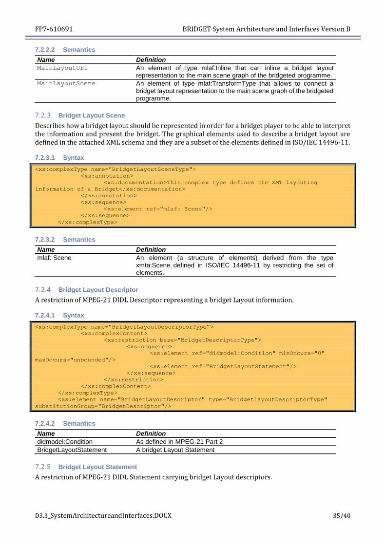
7.2.2.2 Semantics
Name Definition
MainLayoutUrl An element of type mlaf:Inline that can inline a bridget layout representation to the main scene graph of the bridgeted programme.
MainLayoutScene An element of type mlaf:TransformType that allows to connect a bridget layout representation to the main scene graph of the bridgeted programme.
7.2.3 Bridget Layout Scene
Describes how a bridget layout should be represented in order for a bridget player to be able to interpret the information and present the bridget. The graphical elements used to describe a bridget layout are defined in the attached XML schema and they are a subset of the elements defined in ISO/IEC 14496-11.
7.2.3.1 Syntax
<xs:complexType name="BridgetLayoutSceneType">
<xs:annotation>
<xs:documentation>This complex type defines the XMT layouting
information of a Bridget</xs:documentation>
</xs:annotation>
<xs:sequence>
<xs:element ref="mlaf: Scene"/>
</xs:sequence>
</xs:complexType>
7.2.3.2 Semantics
Name Definition
mlaf: Scene An element (a structure of elements) derived from the type xmta:Scene defined in ISO/IEC 14496-11 by restricting the set of elements.
7.2.4 Bridget Layout Descriptor
A restriction of MPEG-21 DIDL Descriptor representing a bridget Layout information.
7.2.4.1 Syntax
<xs:complexType name="BridgetLayoutDescriptorType">
<xs:complexContent>
<xs:restriction base="BridgetDescriptorType">
<xs:sequence>
<xs:element ref="didmodel:Condition" minOccurs="0"
maxOccurs="unbounded"/>
<xs:element ref="BridgetLayoutStatement"/>
</xs:sequence>
</xs:restriction>
</xs:complexContent>
</xs:complexType>
<xs:element name="BridgetLayoutDescriptor" type="BridgetLayoutDescriptorType"
substitutionGroup="BridgetDescriptor"/>
7.2.4.2 Semantics
Name Definition
didmodel:Condition As defined in MPEG-21 Part 2
BridgetLayoutStatement A bridget Layout Statement
7.2.5 Bridget Layout Statement
A restriction of MPEG-21 DIDL Statement carrying bridget Layout descriptors.

FP7-610691 BRIDGET System Architecture and Interfaces Version B
D3.3_SystemArchitectureandInterfaces.DOCX 36/40
7.2.5.1 Syntax
<xs:complexType name="BridgetLayoutStatementType">
<xs:complexContent>
<xs:restriction base="didl:StatementType">
<xs:sequence>
<xs:element name="BridgetLayout" type="LayoutRefType"/>
</xs:sequence>
</xs:restriction>
</xs:complexContent>
</xs:complexType>
<xs:element name="BridgetLayoutStatement" type="BridgetLayoutStatementType"
substitutionGroup="didl:Statement"/>
7.2.5.2 Semantics
Name Definition
BridgetLayout An element of type LayoutRefType
7.2.6 Main Layout Descriptor
A restriction of MPEG-21 DIDL Descriptor representing a Main bridget Layout information.
7.2.6.1 Syntax
<xs:complexType name="MainLayoutDescriptorType">
<xs:complexContent>
<xs:restriction base="didl:DescriptorType">
<xs:sequence>
<xs:element ref="didmodel:Condition" minOccurs="0"
maxOccurs="unbounded"/>
<xs:choice>
<xs:element ref="MainLayoutStatement"/>
</xs:choice>
</xs:sequence>
</xs:restriction>
</xs:complexContent>
</xs:complexType>
<xs:element name="MainLayoutDescriptor" type="MainLayoutDescriptorType"
substitutionGroup="didl:Descriptor"/>
7.2.6.2 Semantics
Name Definition
didmodel:Condition As defined in MPEG-21 Part 2
MainLayoutStatement A Main Layout Statement

FP7-610691 BRIDGET System Architecture and Interfaces Version B
D3.3_SystemArchitectureandInterfaces.DOCX 37/40
7.2.7 Main Layout Statement
A restriction of MPEG-21 DIDL Statement carrying Main bridget Layout descriptors.
7.2.7.1 Syntax
<xs:complexType name="MainLayoutStatementType">
<xs:complexContent>
<xs:restriction base="didl:StatementType">
<xs:sequence>
<xs:element name="MainLayout">
<xs:complexType>
<xs:complexContent>
<xs:extension base="LayoutRefType">
<xs:choice>
<xs:element
name="MainLayoutUri" type="mlaf:InlineType"/>
<xs:element
name="MainLayoutScene" type="mlaf:TransformType"/>
</xs:choice>
</xs:extension>
</xs:complexContent>
</xs:complexType>
</xs:element>
</xs:sequence>
</xs:restriction>
</xs:complexContent>
</xs:complexType>
<xs:element name="MainLayoutStatement" type="MainLayoutStatementType"
substitutionGroup="didl:Statement"/>
7.2.7.2 Semantics
Name Definition
MainLayout An element containing URI or inline definition of Main Layout
MainLayoutUri An URI pointing to a Main Layout
MainLayoutScene Inline description of Main Layout
8 Conclusions
This document it’s a major update to the D3.1 BRIDGET System Architecture and Interfaces – Version A, and describes the final system architecture and infrastructure of BRIDGET, providing an overview of its distributed infrastructure components, internal modules and interfaces.
It describes the evolution of the architecture during this first two year of project, completing the Components description with the related APIs and describing in details the interaction of interconnected parts of the system, according to the project development.
Moreover, it shows the evolution of the BRIDGET environment in order to satisfy all the scenarios selected in [4] and [5], introducing the new End User Authoring Peer and focusing on the importance of the adoption of the Media Linking Application Format.
Finally, a BRIDGET Auditing schema is proposed, defining a generic format to collect and represent measures from BRIDGET clients.

FP7-610691 BRIDGET System Architecture and Interfaces Version B
D3.3_SystemArchitectureandInterfaces.DOCX 38/40
9 Annex A –BRIDGET auditing schema
In this section we propose a possible auditing schema that may be refined during the third year of project by the technical WPs, in order to trace and collect information about End User’s behaviour and usage of the End User Application.
9.1 The BRIDGET auditing schema structure
The BRIDGET auditing schema has been designed in order to provide detailed information to BRIDGET back-end system about End User’s behaviour. The collected information can be eventually stored in a BRIDGET trace collector on the Bridget Content Storage server and used to generate analytics that could be monetized, drive the improvement of the application itself, or provide support for the application debugging.
The BRIDGET tracing will be generated on the End User Application in a XML language, and sent via Get/Post calls on HTTP protocol to the BRIDGET trace collector.
Figure 28 describe the structure of the XML trace schema detailed below.
Figure 28 - BRIDGET tracing XML schema.
<xs:schema elementFormDefault="qualified" xmlns:xs="http://www.w3.org/2001/XMLSchema">
<xs:element name="applicationTracing">
<xs:complexType>
<xs:sequence>
<xs:element ref="general" />
<xs:element ref="measure" maxOccurs="unbounded" />
</xs:sequence>
</xs:complexType>
</xs:element>
<xs:element name="general">
<xs:complexType>
<xs:attribute name="mcaddress" type="xs:string" use="optional" />
<xs:attribute name="hardwareModel" type="xs:string" use="optional" />
<xs:attribute name="hardwareName" type="xs:string" use="optional" />
<xs:attribute name="softwareVersion" type="xs:string" use="optional" />
<xs:attribute name="application" type="xs:string" use="optional" />
<xs:attribute name="hardwareType" type="xs:string" use="optional" />
<xs:attribute name="IP" type="xs:string" use="optional" />
</xs:complexType>
</xs:element>
<xs:element name="measure">

FP7-610691 BRIDGET System Architecture and Interfaces Version B
D3.3_SystemArchitectureandInterfaces.DOCX 39/40
<xs:complexType>
<xs:sequence>
<xs:element ref="param" minOccurs="0" maxOccurs="unbounded" />
</xs:sequence>
<xs:attribute name="name" type="xs:string" use="required" />
<xs:attribute name="time" type="xs:string" use="required" />
</xs:complexType>
</xs:element>
<xs:element name="param">
<xs:complexType>
<xs:attribute name="name" type="xs:string" use="optional" />
<xs:attribute name="value" type="xs:string" use="optional" />
</xs:complexType>
</xs:element>
</xs:schema>
The root element applicationTracing is made up of one general element and one or more measure element.
The general element provides specific client application parameters, and its attributes are extensible if needed without any modification to the XML schema.
The measure elements provide detailed information through their specific attributes name (what we are measuring), time (how long does the action go on) and a sequence of param.
Every applicationTracing provides at least one measure with name=StartTracing and one measure con name=StopTracing.
The schema proposed is very flexible and it should easily adapt to the present and future Bridget tracing purposes.
We briefly provide a sample of a trace that could be generated by the End User’s application through the selection of one bridget related to the Gulp Girl scenario defined in [4].
<applicationTracing>
<general softwareVersion="2.01" mcaddress="00:00:00:00:00:00" hardwareModel="P8" hardwareName="Huawei" application="Bridget" hardwareType="Smartphone IP=" 80.20.149.215 " />
<measure name="StartTracing " time="22/01/2016-12:19:34.355 " />
<measure name="SpecificTracingEvent " time="22/01/2016-12:23:14.277 ">
<param name="contentProvider " value="RAI " />
<param name="section" value="GULP GIRL" />
<param name="action" value="bridgetSelected" />
<param name="assetID" value="bridgetInternalId_50245879" />
<param name="contentTitle " value="hilary_swank_1" />
</measure>
<measure name="StopTracing " time="22/01/2016-12:24:01.090 " />
</applicationTracing>

FP7-610691 BRIDGET System Architecture and Interfaces Version B
D3.3_SystemArchitectureandInterfaces.DOCX 40/40
10 References
[1] BRIDGET, System Architecture and Interfaces - Version A, Deliverable D3.1v1, 2014/06/30
[2] BRIDGET, Requirements and Functionalities - Version B, Deliverable D2.5v2, 2015/12/31
[3] ISO/IEC 23000-18 DIS Media Linking Application Format (October 2015)
[4] BRIDGET, First BRIDGET Workshop and Use Scenarios – Version A , Deliverable D2.1v1,
2014/01/31.
[5] BRIDGET, Second BRIDGET Workshop and Use Scenarios – Version B, Deliverable D2.4v2,
2015/11/30
[6] BRIDGET, Proof-of-Concept Prototypes Specification – Version B, Deliverable D8.6v2,
2016/01/31
[7] ISO/IEC JTC1/SC29/WG11 N13869, " White Paper on the MPEG-7 AudioVisual Description
Profile (AVDP)", Vienna, Austria, August 2013 (available at
http://mpeg.chiariglione.org/sites/default/files/files/standards/docs/w13869%20_AVDP_Whi
tePaper_final.docx
[8] DIS ISO/IEC 23000-8, “Information technology – MPEG Application Formats – Part 18 Media
Linking Application Format”.
[9] ISO/IEC 14496-11:2005, “Information technology -- Coding of audio-visual objects -- Part 11:
Scene description and application engine”
[10] ISO/IEC 21000-2, “Information technology – Multimedia framework (MPEG-21) – Part 2:
Digital Item Declaration”
[11] ISO/IEC 15938-5, “Information technology – Multimedia content description interface
(MPEG-7) – Part 5: Multimedia description schemes”
[12] EBU Tech 3293, EBU Core Metadata Set ver. 1.5
[13] DIS ISO/IEC 21000-22, “Information technology – Multimedia framework (MPEG-21) –
Part 22: User Description”