
BRIDGE RESPONSE TO NEAR-FIELD GROUND...
20
1 1 Bri. Resp. - BRIDGE RESPONSE TO BRIDGE RESPONSE TO NEAR NEAR- FIELD GROUND MOTIONS FIELD GROUND MOTIONS Genda Chen*, Ph.D., P.E., and Genda Chen*, Ph.D., P.E., and Mostafa Mostafa El El- Engebawy Engebawy , Ph.D. , Ph.D. *Associate Professor of Civil Engineering *Associate Professor of Civil Engineering Department of Civil, Architecture and Environmental Engineering Department of Civil, Architecture and Environmental Engineering University of Missouri University of Missouri- Rolla Rolla [email protected] [email protected] Geotechnical and Bridge Seismic Design Workshop Geotechnical and Bridge Seismic Design Workshop New Madrid Seismic Zone Experience New Madrid Seismic Zone Experience October 28 October 28- 29, 2004 29, 2004 2 Bri. Resp. - Participants Participants Genda Chen, Ph.D., P.E. (Team Leader) Genda Chen, Ph.D., P.E. (Team Leader) Mostafa Mostafa El El- Engebawy Engebawy , Ph.D. , Ph.D. Ronaldo Ronaldo Luna, Ph.D., P.E. Luna, Ph.D., P.E. Richard Stephenson, Ph.D., P.E. Richard Stephenson, Ph.D., P.E. Wei Wei Zheng Zheng, Ph.D. Graduate Student , Ph.D. Graduate Student Wenxig Wenxig Liu, Ph.D. Graduate Student Liu, Ph.D. Graduate Student
Transcript of BRIDGE RESPONSE TO NEAR-FIELD GROUND...

1
1Bri. Resp. -
BRIDGE RESPONSE TO BRIDGE RESPONSE TO NEARNEAR--FIELD GROUND MOTIONSFIELD GROUND MOTIONS
Genda Chen*, Ph.D., P.E., and Genda Chen*, Ph.D., P.E., and MostafaMostafa ElEl--EngebawyEngebawy, Ph.D., Ph.D.*Associate Professor of Civil Engineering*Associate Professor of Civil Engineering
Department of Civil, Architecture and Environmental EngineeringDepartment of Civil, Architecture and Environmental EngineeringUniversity of MissouriUniversity of Missouri--RollaRolla
[email protected]@umr.edu
Geotechnical and Bridge Seismic Design WorkshopGeotechnical and Bridge Seismic Design WorkshopNew Madrid Seismic Zone ExperienceNew Madrid Seismic Zone Experience
October 28October 28--29, 2004 29, 2004
2Bri. Resp. -
ParticipantsParticipants
Genda Chen, Ph.D., P.E. (Team Leader)Genda Chen, Ph.D., P.E. (Team Leader)MostafaMostafa ElEl--EngebawyEngebawy, Ph.D., Ph.D.
RonaldoRonaldo Luna, Ph.D., P.E.Luna, Ph.D., P.E.Richard Stephenson, Ph.D., P.E.Richard Stephenson, Ph.D., P.E.
WeiWei ZhengZheng, Ph.D. Graduate Student, Ph.D. Graduate StudentWenxigWenxig Liu, Ph.D. Graduate StudentLiu, Ph.D. Graduate Student

2
3Bri. Resp. -
Outline of PresentationOutline of PresentationObjectivesObjectivesDescription of Bridge SystemsDescription of Bridge SystemsFoundation Model and Bridge ModelFoundation Model and Bridge ModelDynamic Characteristics of Selected BridgesDynamic Characteristics of Selected BridgesDiscussion of ResultsDiscussion of Results
Influence of Rupture DirectivityInfluence of Rupture DirectivityInfluence of Vertical AccelerationInfluence of Vertical AccelerationInfluence of LiquefactionInfluence of LiquefactionComparison with FarComparison with Far--Field Ground MotionsField Ground Motions
Concluding RemarksConcluding RemarksRecommendations for including NearRecommendations for including Near--Field Effects in Field Effects in Highway Bridge DesignHighway Bridge Design
4Bri. Resp. -
ObjectivesObjectives
To evaluate the response of a multiTo evaluate the response of a multi--span simply span simply supported bridge (L472) and a multisupported bridge (L472) and a multi--span continuous span continuous bridge (A1466) to nearbridge (A1466) to near--field ground motions from field ground motions from future earthquake scenarios in the NMSZfuture earthquake scenarios in the NMSZTo compare the bridge response subjected to nearTo compare the bridge response subjected to near--field field ground motions simulated using the compositeground motions simulated using the composite--source source model with that of farmodel with that of far--field motions of the pointfield motions of the point--source modelsource modelTo To recommend a simple method for including nearrecommend a simple method for including near--field effects in highway bridge designfield effects in highway bridge design
3
5Bri. Resp. -
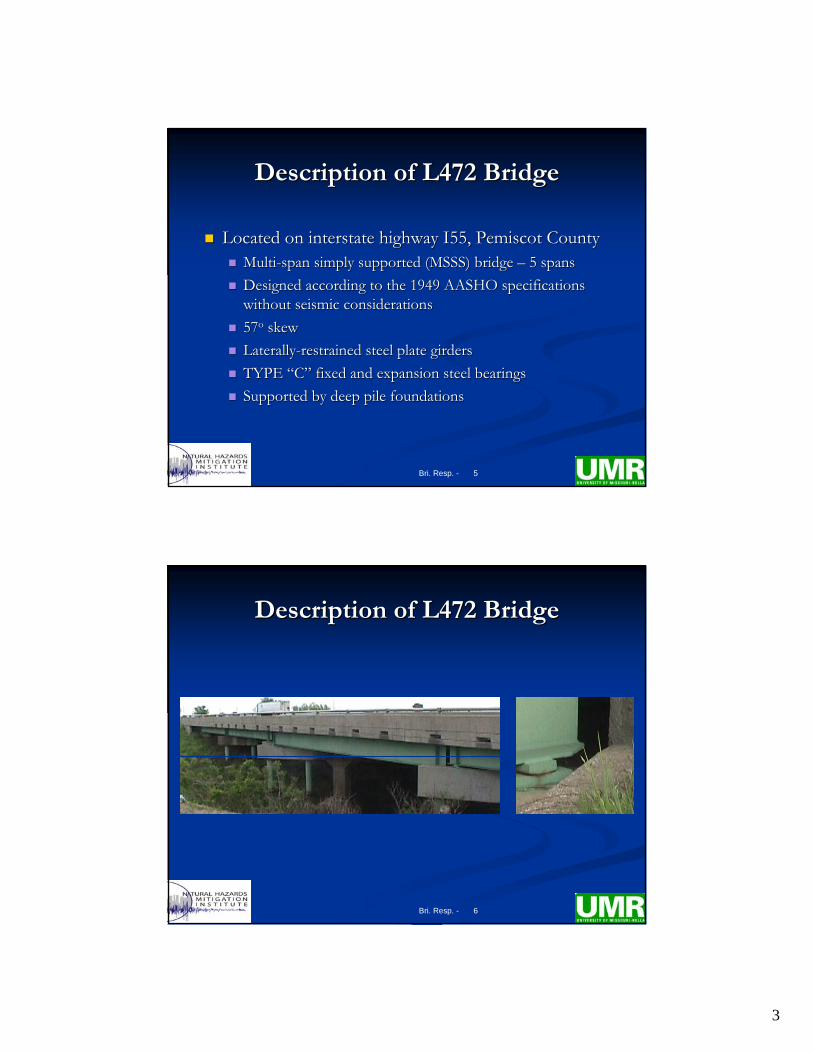
Description of L472 BridgeDescription of L472 Bridge
Located on interstate highway I55, Pemiscot CountyLocated on interstate highway I55, Pemiscot CountyMultiMulti--span simply supported (MSSS) bridge span simply supported (MSSS) bridge –– 5 spans5 spansDesigned according to the 1949 AASHO specifications Designed according to the 1949 AASHO specifications without seismic considerationswithout seismic considerations5757oo skewskewLaterallyLaterally--restrained steel plate girders restrained steel plate girders TYPE TYPE ““CC”” fixed and expansion steel bearingsfixed and expansion steel bearingsSupported by deep pile foundationsSupported by deep pile foundations
6Bri. Resp. -
Description of L472 BridgeDescription of L472 Bridge

4
7Bri. Resp. -
Ground surface XZ
X (longitudinal direction)
Y (transverse direction)
12 3
15°
Southwestern segment
Center of span between bents 3–4
O
x'
y'
Description of L472 BridgeDescription of L472 Bridge
8Bri. Resp. -
Description of A1466 BridgeDescription of A1466 Bridge
Located on interstate highway I55, Pemiscot CountyLocated on interstate highway I55, Pemiscot CountyMultiMulti--span continuous bridge span continuous bridge –– 4 spans4 spansDesigned according to the 1949 AASHO specifications Designed according to the 1949 AASHO specifications without seismic considerationswithout seismic considerations1010oo skewskewLaterallyLaterally--restrained steel plate girders restrained steel plate girders TYPE TYPE ““DD”” fixed and expansion steel bearingsfixed and expansion steel bearingsSupported by deep pile foundationsSupported by deep pile foundations

5
9Bri. Resp. -
Description of A1466 BridgeDescription of A1466 Bridge
Ground surface X
Z
Southwestern segment
X
Y
12° O
x'
y'
10Bri. Resp. -
Foundation ModelFoundation Model

6
11Bri. Resp. -
Bridge ModelBridge Model
Initial stiffness of all RC elements to account for Initial stiffness of all RC elements to account for concrete cracking, confinement, reinforcement yielding, concrete cracking, confinement, reinforcement yielding, and expected level of axial forcesand expected level of axial forces
Nonlinear elements to account for:Nonlinear elements to account for:Plastic zones at the top and bottom of columnsPlastic zones at the top and bottom of columnsTYPE TYPE ““CC”” and and ““DD”” expansion bearings expansion bearings PoundingPounding
12Bri. Resp. -
Bridge ModelBridge ModelStressStress--Strain RelationsStrain Relations
0
5
10
15
20
25
0.000 0.005 0.010 0.015Compressive strain
Com
p. s
tress
(MPa
) Unconfined concreteConfined concrete
0
100
200
300
400
500
0.00 0.05 0.10 0.15 0.20 0.25Strain
Stre
ss (M
Pa)

7
13Bri. Resp. -
0
100
200
300
400
500
0 0.01 0.02 0.03 0.04 0.05 0.06Curvature (1/m)
Mom
ent (
kN-m
)
0
200
400
600
800
1000
0 0.005 0.01 0.015 0.02Curvature (1/m)
Mom
ent (
kN-m
)
8#7 #[email protected]
0.76m
8#10
0.91m
L472 Bridge ColumnsL472 Bridge Columns A1466 Bridge ColumnsA1466 Bridge Columns
Bridge ModelBridge ModelMomentMoment--Curvature AnalysisCurvature Analysis
14Bri. Resp. -
Dynamic Characteristics Dynamic Characteristics L472 Bridge L472 Bridge –– Fundamental mode of vibrationFundamental mode of vibration
TToo = 0.70 sec= 0.70 sec

8
15Bri. Resp. -
Dynamic Characteristics Dynamic Characteristics L472 Bridge L472 Bridge –– Second mode of vibrationSecond mode of vibration
TToo = 0.55 sec= 0.55 sec
16Bri. Resp. -
Dynamic Characteristics Dynamic Characteristics A1466 Bridge A1466 Bridge –– Fundamental mode of vibrationFundamental mode of vibration
TToo = 1.89 sec= 1.89 sec

9
17Bri. Resp. -
Dynamic Characteristics Dynamic Characteristics A1466 Bridge A1466 Bridge –– Second mode of vibrationSecond mode of vibration
TToo = 0.43 sec= 0.43 sec
18Bri. Resp. -
Discussion of ResultsDiscussion of Results

10
19Bri. Resp. -
Influence of Rupture Directivity (L472)Influence of Rupture Directivity (L472)
36°N
37°N
Latit
ude
Southwestern segment L472 bridge site Epicenter #32
36°N
37°NLa
titud
e Southwestern segment L472 bridge site Epicenter #82
X COS X COS θθ is NAis NA
X COS X COS θθ = 0.45= 0.45
MMW W 7.0 7.0
20Bri. Resp. -
Influence of Rupture Directivity (L472)Influence of Rupture Directivity (L472)
-2.0
-1.0
0.0
1.0
2.0
0 20 40 60 80Time (sec)
Vel
ocity
(m/s
ec)
-2.0
-1.0
0.0
1.0
2.0
0 20 40 60 80Time (sec)
Vel
ocity
(m/s
ec)
Sim #82 Sim #82 –– FN rock motion FN rock motion with velocity pulseswith velocity pulses
Sim #32 Sim #32 –– FN rock motionFN rock motionwithout velocity pulseswithout velocity pulses

11
21Bri. Resp. -
Influence of Rupture Directivity (L472)Influence of Rupture Directivity (L472)
-2.0
-1.0
0.0
1.0
2.0
0 20 40 60 80Time (sec)
Vel
ocity
(m/s
ec)
-2.0
-1.0
0.0
1.0
2.0
0 20 40 60 80Time (sec)
Vel
ocity
(m/s
ec)
Sim #82 Sim #82 –– FN ground motion FN ground motion with velocity pulseswith velocity pulses
Sim #32 Sim #32 –– FN ground motionFN ground motionwithout velocity pulseswithout velocity pulses
22Bri. Resp. -
Influence of Rupture Directivity (L472)Influence of Rupture Directivity (L472)
Sim #82 Sim #82 –– FN ground motion FN ground motion with displacement pulseswith displacement pulses
Sim #32 Sim #32 –– FN ground motionFN ground motionwithout displacement pulseswithout displacement pulses
-2.0
-1.0
0.0
1.0
2.0
0 20 40 60 80Time (sec)
Dis
plac
emen
t (m
)
-2.0
-1.0
0.0
1.0
2.0
0 20 40 60 80Time (sec)
Dis
plac
emen
t (m
)

12
23Bri. Resp. -
Influence of Rupture Directivity (L472)Influence of Rupture Directivity (L472)
3.23.23.13.1dd2.72.72.52.5cc2.82.82.32.3bb2.32.31.71.7aa
Sim Sim #82#82
Sim Sim #32#32LocationLocation
Bent Bent # 2# 2
Bent Bent # 3# 3
Bent Bent # 1# 1
aa
bbcc
dd
MMW W 7.0 7.0
InIn--planeplanecurvature ductilitycurvature ductility
24Bri. Resp. -
Influence of Vertical Acceleration (L472)Influence of Vertical Acceleration (L472)
--897897--16621662dd
--12791279--17411741cc
--796796--16791679bb
--10061006--13861386aa
withoutwithoutVV
withwithVV
LocationLocation
Bent Bent # 2# 2
Bent Bent # 3# 3
Bent Bent # 1# 1
aa
bbcc
dd
MMW W 7.5 7.5
Compressive forceCompressive force
13
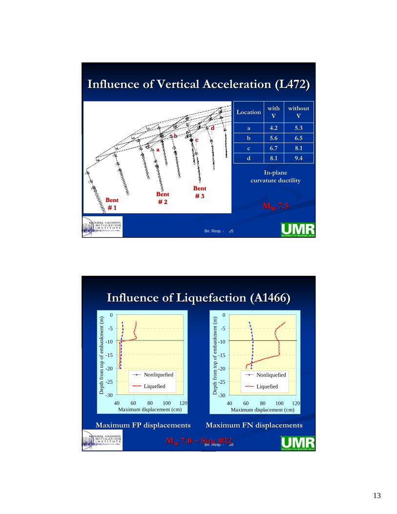
25Bri. Resp. -
Influence of Vertical Acceleration (L472)Influence of Vertical Acceleration (L472)
9.49.48.18.1dd
8.18.16.76.7cc
6.56.55.65.6bb
5.35.34.24.2aa
withoutwithoutVV
withwithVV
LocationLocation
Bent Bent # 2# 2
Bent Bent # 3# 3
Bent Bent # 1# 1
aa
bbcc
dd
MMW W 7.5 7.5
InIn--planeplanecurvature ductilitycurvature ductility
26Bri. Resp. -
Influence of Liquefaction (A1466)Influence of Liquefaction (A1466)
-30
-25
-20
-15
-10
-5
0
40 60 80 100 120Maximum displacement (cm)
Dep
th fr
om to
p of
em
bank
men
t (m
)
Nonliquefied
Liquefied-30
-25
-20
-15
-10
-5
0
40 60 80 100 120Maximum displacement (cm)
Dep
th fr
om to
p of
em
bank
men
t (m
)
Nonliquefied
Liquefied
Maximum FP displacementsMaximum FP displacements
MMW W 7.0 7.0 –– Sim #12Sim #12
Maximum FN displacementsMaximum FN displacements

14
27Bri. Resp. -
Influence of Liquefaction (A1466)Influence of Liquefaction (A1466)
FP at bottom of embankmentFP at bottom of embankment FN at bottom of embankmentFN at bottom of embankment
MMW W 7.0 7.0 –– Sim #12Sim #12
-1.0
-0.5
0.0
0.5
1.0
0 20 40 60 80Time (sec)
Dis
plac
emen
t (m
)
Liquefied Nonliquefied
-1.0
-0.5
0.0
0.5
1.0
0 20 40 60 80Time (sec)
Dis
plac
emen
t (m
)
Liquefied Nonliquefied
28Bri. Resp. -
Influence of Liquefaction (A1466)Influence of Liquefaction (A1466)
FP at top of embankmentFP at top of embankment FN at top of embankmentFN at top of embankment
-1.0
-0.5
0.0
0.5
1.0
0 20 40 60 80Time (sec)
Dis
plac
emen
t (m
)
Liquefied Nonliquefied
-1.0
-0.5
0.0
0.5
1.0
0 20 40 60 80Time (sec)
Dis
plac
emen
t (m
)
Liquefied Nonliquefied
MMW W 7.0 7.0 –– Sim #12Sim #12

15
29Bri. Resp. -
Influence of Liquefaction (A1466)Influence of Liquefaction (A1466)
MMW W 7.0 7.0 –– Sim #12Sim #12
6.36.318.918.9dd
6.46.431.031.0cc
6.16.120.220.2bb
6.36.331.631.6aa
without without LIQLIQ
withwithLIQLIQ
LocationLocation
Bent Bent # 2# 2
Bent Bent # 3# 3Abutment Abutment
# 1# 1
aa
bb
cc
dd
InIn--planeplanecurvature ductilitycurvature ductility
30Bri. Resp. -
Comparison with FarComparison with Far--Field MotionsField Motions
Rock motionsRock motions Ground motionsGround motions
0
1
2
3
4
5
0 1 2 3 4 5Period (sec)
Spec
tral a
ccel
erat
ion
(g)
Fault-parallel Fault-normal Point-source
0
1
2
3
4
5
0 1 2 3 4 5Period (sec)
Spec
tral a
ccel
erat
ion
(g)
Fault-parallel Fault-normal Point-source
MMW W 7.5 7.5 –– L472L472

16
31Bri. Resp. -
Comparison with FarComparison with Far--Field MotionsField Motions
Motions applied along the Motions applied along the longitudinal axislongitudinal axis of the bridgeof the bridge
MMW W 7.5 7.5 –– L472L472
2.32.36.76.7dd
1.81.85.95.9cc
1.91.95.25.2bb
1.61.64.44.4aa
PointPoint--sourcesource
CompositeComposite--sourcesource
LocationLocation
Bent Bent # 2# 2
Bent Bent # 3# 3Abutment Abutment
# 1# 1
aa
bb
cc
dd
InIn--planeplanecurvature ductilitycurvature ductility
32Bri. Resp. -
Comparison with FarComparison with Far--Field MotionsField Motions
Motions applied along the Motions applied along the transverse axistransverse axis of the bridgeof the bridge
MMW W 7.5 7.5 –– L472L472
1.31.34.54.5dd
1.11.14.04.0cc
1.11.13.23.2bb
1.01.02.72.7aa
PointPoint--sourcesource
CompositeComposite--sourcesource
LocationLocation
Bent Bent # 2# 2
Bent Bent # 3# 3Abutment Abutment
# 1# 1
aa
bb
cc
dd
InIn--planeplanecurvature ductilitycurvature ductility

17
33Bri. Resp. -
Recommendations for Recommendations for including Nearincluding Near--Field Effects Field Effects in Highway Bridge Designin Highway Bridge Design
Based on AbrahamsonBased on Abrahamson’’s model (2000) and s model (2000) and Somerville et al. (1997) Somerville et al. (1997)
34Bri. Resp. -
Directivity modelDirectivity model
STEP ISTEP IScale factor for the average horizontal component AvH Scale factor for the average horizontal component AvH (after Abrahamson, 2000)(after Abrahamson, 2000)
ln[Dir(X, ln[Dir(X, θθ, T)] = C1(T) + 1.88 C2(T) XCos, T)] = C1(T) + 1.88 C2(T) XCosθθ XCosXCosθθ ≤≤ 0.40.4ln[Dir(X, ln[Dir(X, θθ, T)] = C1(T) + 0.75 C2(T) XCos, T)] = C1(T) + 0.75 C2(T) XCosθθ > 0.4> 0.4
STEP IISTEP IIDifference between FN and FP components of motion Difference between FN and FP components of motion (after Somerville et al., 1997) (after Somerville et al., 1997)
ln(FN/AvH) = Cos(2ln(FN/AvH) = Cos(2θθ) [C3(T) + C4(T) ln(r) [C3(T) + C4(T) ln(rruprup+1) + C5(M+1) + C5(MWW--6)] 6)] θθ < 45< 45°°ln(FN/AvH) = 0 ln(FN/AvH) = 0 θθ ≥≥ 4545°°ln(FP/AvH) = ln(FP/AvH) = --ln(FN/AvH) ln(FN/AvH)

18
35Bri. Resp. -
Upper bound of Directivity ConditionsUpper bound of Directivity Conditions
Assuming XCosAssuming XCosθθ=0.40 then =0.40 then θθ=4.4=4.4°° for for L472 bridge (3.7 km from fault)L472 bridge (3.7 km from fault)
L472 site - Mw 7.5
0.0
1.0
2.0
3.0
4.0
0 1 2 3 4 5Period (sec)
Spec
tral A
ccel
erat
ion
(g)
Fault-parallel
FP upper bound
ATC/MCEER
L472 site - Mw 7.5
0.0
1.0
2.0
3.0
4.0
5.0
0 1 2 3 4 5Period (sec)
Spec
tral A
ccel
erat
ion
(g)
Fault-normal
FN upper bound
ATC/MCEER
36Bri. Resp. -
Upper bound of Directivity ConditionsUpper bound of Directivity Conditions
Assuming XCosAssuming XCosθθ=0.40 then =0.40 then θθ=12.5=12.5°° for for A1466 bridge (10.9 km from fault)A1466 bridge (10.9 km from fault)
A1466 site - Mw 7.5
0.0
1.0
2.0
3.0
0 1 2 3 4 5Period (sec)
Spec
tral A
ccel
erat
ion
(g)
Fault-parallel
FP upper bound
ATC/MCEER
A1466 site - Mw 7.5
0.0
1.0
2.0
3.0
0 1 2 3 4 5Period (sec)
Spec
tral A
ccel
erat
ion
(g)
Fault-normal
FN upper bound
ATC/MCEER

19
37Bri. Resp. -
Average Directivity ConditionsAverage Directivity Conditions
Assuming the epicenter at the middle of the fault then XCosAssuming the epicenter at the middle of the fault then XCosθθ=0.24 and =0.24 and θθ=19.5=19.5°° for for A1466 bridge (10.9 km from fault)A1466 bridge (10.9 km from fault)
A1466 site - Mw 7.5
0.0
1.0
2.0
3.0
0 1 2 3 4 5Period (sec)
Spec
tral A
ccel
erat
ion
(g)
Fault-parallel
Average directivity
ATC/MCEER
A1466 site - Mw 7.5
0.0
1.0
2.0
3.0
0 1 2 3 4 5Period (sec)
Spec
tral A
ccel
erat
ion
(g)
Fault-normal
Average directivity
ATC/MCEER
38Bri. Resp. -
Concluding RemarksConcluding Remarks
The curvature ductility ratio of columns increase significantly The curvature ductility ratio of columns increase significantly with the moment magnitude. Forward rupture directivity and with the moment magnitude. Forward rupture directivity and liquefaction effects are the dominant reasons for the high ratioliquefaction effects are the dominant reasons for the high ratioss
The vertical acceleration increases the compressive forces in thThe vertical acceleration increases the compressive forces in the e columns under the maximum considered earthquake. They are columns under the maximum considered earthquake. They are remarkably reduced with lower moment magnitudesremarkably reduced with lower moment magnitudes
Liquefaction yields large displacements in the faultLiquefaction yields large displacements in the fault--normal normal direction and permanent offset of the soil near the top of the direction and permanent offset of the soil near the top of the embankment that develop extreme large deformations in the embankment that develop extreme large deformations in the plane of the bridge bents leading to large inplane of the bridge bents leading to large in--plane curvature plane curvature ductility ratios of the columnsductility ratios of the columns

20
39Bri. Resp. -
RecommendationsRecommendations
A siteA site--specific rock and ground motion simulations are specific rock and ground motion simulations are recommended for highway bridges within 10 km from active recommended for highway bridges within 10 km from active faults in the NMSZ. The resulting rock motions should include faults in the NMSZ. The resulting rock motions should include forward rupture directivity while fling step is not likely to ocforward rupture directivity while fling step is not likely to occur cur in future earthquake eventsin future earthquake events
For highway bridges located beyond 10 km, a simple For highway bridges located beyond 10 km, a simple methodology is recommended for considering nearmethodology is recommended for considering near--field effects field effects in their design response spectra based on the average directivitin their design response spectra based on the average directivity y conditions at the site and the directivity models of Abrahamson conditions at the site and the directivity models of Abrahamson (2000) and Somerville et al. (1997)(2000) and Somerville et al. (1997)