Bridge Piers with Structural Fuses and Bi-Steel Columns. I: Experimental Testingbruneau/ASCE 2012...
11
Bridge Piers with Structural Fuses and Bi-Steel Columns. I: Experimental Testing Samer El-Bahey 1 and Michel Bruneau, F.ASCE 2 Abstract: Structural fuses, easily replaceable sacrificial elements to dissipate seismic energy while preventing damage to the gravity load- resisting structural system, are proposed as part of a multicolumn accelerated bridge construction (ABC) pier concept. Different types of structural fuses are investigated to compare the effect of each on ABC bridge bents. The piers of a three span-continuous bridge prototypes having two twin-column pier bents were designed using double-composite rectangular columns and structural fuses. Two corresponding 2=3- scale models were developed and were subjected to cyclic quasi-static tests. For the first specimen, steel-plate shear links (SPSLs) were installed between the columns as a series of structural fuses. Testing was performed, first up to a drift corresponding to the onset of columns yielding to investigate the effectiveness of adding the fuses in dissipating the seismic energy, then up to failure of the composite columns. The second tested specimen has buckling restrained braces (BRBs) as a series of structural fuses between the columns. The BRBs were then removed, and a cyclic test of the composite bent continued until failure of the columns. Both specimens exhibited stable hysteretic behavior, with the structural fuses also increasing stiffness and strength of the bent. Individual testing results for the SPSLs with various geometries and boundary conditions are then presented. DOI: 10.1061/(ASCE)BE.1943-5592.0000234. © 2012 American Society of Civil Engineers. CE Database subject headings: Buckling; Bracing; Steel columns; Seismic effects; Bridges; Piers. Author keywords: Structural fuses; Buckling restrained braces; Steel plate shear links; Seismic; Bridges. Introduction Earthquakes can cause significant damage to bridge substructures. Providing reliable mechanisms for dissipation of the destructive earthquake energy is key, both for safety and to limit the forces in structural members. The concept of designing sacrificial mem- bers to dissipate the seismic energy, while preserving the integrity of other main components, is known as the structural fuse concept. The term structural fuse can be found in the literature at least going back to Roeder and Popov (1977) as part of their proposed eccentri- cally braced frame concept for steel frames and in much subsequent research (e.g., Fintel and Ghosh (1981) used a similar capacity de- sign concept and designated plastic hinging of the beams to be structural fuses), although in much past research, the fuses were not easily replaceable. Wada et al. (1992) expanded on the struc- tural fuse concept by defining damage-controlled or damage toler- ant structures in which the structure was considered as two separate components, namely, a moment frame designed to resist 80% of the lateral loads and, second, special bracing as passive energy dissi- pation elements dedicated to provide energy dissipation under the loads resulting from strong ground motions. Conner et al. (1997) demonstrated that the effectiveness of the damage-controlled struc- tures concept depends on the energy dissipation capacity of the bracing devices used and the ability of the primary structure to remain elastic during a major seismic event, which is more easily achieved when high strength materials, for the primary structure are combined with low strength ones for the bracing system. Further developments were proposed by Shimizu et al. (1998), Wada and Huang (1999), and Huang et al. (2002). Wada and Huang (1995) implemented an approach on the basis of the balance of energy to design tall building structures having either hysteretic dampers or viscous dampers. A comprehensive study of damage-controlled structures in Japan was presented by Wada et al. (2000). That paper presented some research work done on the development of the damage-controlled structures concept and its potential to design new constructions and to retrofit existing structures. A dynamic analysis method was proposed for three-dimensional frames with elements used to develop the structural fuse concept. Building on that prior work, Vargas and Bruneau (2009a, b) provided a system- atic design procedure to achieve a structural fuse concept to limit damage to disposable structural elements for any general structure, without the need for complex analyses. All the previous work on the structural fuse concept focused on implementations in buildings. While inelastic deformations have been relied upon to achieve ductile performance for bridges, implementation of the structural fuse concept has not been imple- mented in standard bridge’ s piers [although replaceable fuses have been implemented between the towers of one signature bridge (Goodyear and Sun 2003], and it can be argued that ductile dia- phragm concepts (Bruneau et al. 2002) embody the same princi- ples. One such structural fuse concept for a bridge pier, which could be of benefit for both new and existing bridges, is considered here. Here, fuses are added to a two-column bridge bent to increase its strength and stiffness, while dissipating the seismic energy through hysteretic behavior and while keeping the bridge columns elastic. The bridge bent in this particular application consists of segmental composite columns built in stacked segments but con- tinuous after concrete curing. Several types of structural fuses can be used in bridges; the focus here is on two specific types, 1 Structural Engineer, Stevenson & Associates, Phoenix, AZ (corre- sponding author). E-mail: [email protected] 2 Professor, Dept. of Civil, Structural, and Environmental Engineering, State University of New York, Buffalo, NY. Note. This manuscript was submitted on August 12, 2010; approved on February 22, 2011; published online on February 24, 2011. Discussion per- iod open until June 1, 2012; separate discussions must be submitted for individual papers. This paper is part of the Journal of Bridge Engineering, Vol. 17, No. 1, January 1, 2012. ©ASCE, ISSN 1084-0702/2012/1-25–35/ $25.00. JOURNAL OF BRIDGE ENGINEERING © ASCE / JANUARY/FEBRUARY 2012 / 25
Transcript of Bridge Piers with Structural Fuses and Bi-Steel Columns. I: Experimental Testingbruneau/ASCE 2012...
Bridge Piers with Structural Fuses and Bi-Steel Columns.I: Experimental Testing
Samer El-Bahey1 and Michel Bruneau, F.ASCE2
Abstract: Structural fuses, easily replaceable sacrificial elements to dissipate seismic energy while preventing damage to the gravity load-resisting structural system, are proposed as part of a multicolumn accelerated bridge construction (ABC) pier concept. Different types ofstructural fuses are investigated to compare the effect of each on ABC bridge bents. The piers of a three span-continuous bridge prototypeshaving two twin-column pier bents were designed using double-composite rectangular columns and structural fuses. Two corresponding 2=3-scale models were developed and were subjected to cyclic quasi-static tests. For the first specimen, steel-plate shear links (SPSLs) wereinstalled between the columns as a series of structural fuses. Testing was performed, first up to a drift corresponding to the onset of columnsyielding to investigate the effectiveness of adding the fuses in dissipating the seismic energy, then up to failure of the composite columns. Thesecond tested specimen has buckling restrained braces (BRBs) as a series of structural fuses between the columns. The BRBs were thenremoved, and a cyclic test of the composite bent continued until failure of the columns. Both specimens exhibited stable hysteretic behavior,with the structural fuses also increasing stiffness and strength of the bent. Individual testing results for the SPSLs with various geometries andboundary conditions are then presented. DOI: 10.1061/(ASCE)BE.1943-5592.0000234. © 2012 American Society of Civil Engineers.
CE Database subject headings: Buckling; Bracing; Steel columns; Seismic effects; Bridges; Piers.
Author keywords: Structural fuses; Buckling restrained braces; Steel plate shear links; Seismic; Bridges.
Introduction
Earthquakes can cause significant damage to bridge substructures.Providing reliable mechanisms for dissipation of the destructiveearthquake energy is key, both for safety and to limit the forcesin structural members. The concept of designing sacrificial mem-bers to dissipate the seismic energy, while preserving the integrityof other main components, is known as the structural fuse concept.The term structural fuse can be found in the literature at least goingback to Roeder and Popov (1977) as part of their proposed eccentri-cally braced frame concept for steel frames and in much subsequentresearch (e.g., Fintel and Ghosh (1981) used a similar capacity de-sign concept and designated plastic hinging of the beams to bestructural fuses), although in much past research, the fuses werenot easily replaceable. Wada et al. (1992) expanded on the struc-tural fuse concept by defining damage-controlled or damage toler-ant structures in which the structure was considered as two separatecomponents, namely, a moment frame designed to resist 80% of thelateral loads and, second, special bracing as passive energy dissi-pation elements dedicated to provide energy dissipation under theloads resulting from strong ground motions. Conner et al. (1997)demonstrated that the effectiveness of the damage-controlled struc-tures concept depends on the energy dissipation capacity of thebracing devices used and the ability of the primary structure toremain elastic during a major seismic event, which is more easily
achieved when high strength materials, for the primary structure arecombined with low strength ones for the bracing system. Furtherdevelopments were proposed by Shimizu et al. (1998), Wada andHuang (1999), and Huang et al. (2002). Wada and Huang (1995)implemented an approach on the basis of the balance of energy todesign tall building structures having either hysteretic dampers orviscous dampers. A comprehensive study of damage-controlledstructures in Japan was presented by Wada et al. (2000). That paperpresented some research work done on the development of thedamage-controlled structures concept and its potential to designnew constructions and to retrofit existing structures. A dynamicanalysis method was proposed for three-dimensional frames withelements used to develop the structural fuse concept. Building onthat prior work, Vargas and Bruneau (2009a, b) provided a system-atic design procedure to achieve a structural fuse concept to limitdamage to disposable structural elements for any general structure,without the need for complex analyses.All the previous work on the structural fuse concept focused
on implementations in buildings. While inelastic deformationshave been relied upon to achieve ductile performance for bridges,implementation of the structural fuse concept has not been imple-mented in standard bridge’s piers [although replaceable fuses havebeen implemented between the towers of one signature bridge(Goodyear and Sun 2003], and it can be argued that ductile dia-phragm concepts (Bruneau et al. 2002) embody the same princi-ples. One such structural fuse concept for a bridge pier, whichcould be of benefit for both new and existing bridges, is consideredhere. Here, fuses are added to a two-column bridge bent to increaseits strength and stiffness, while dissipating the seismic energythrough hysteretic behavior and while keeping the bridge columnselastic. The bridge bent in this particular application consists ofsegmental composite columns built in stacked segments but con-tinuous after concrete curing. Several types of structural fusescan be used in bridges; the focus here is on two specific types,
1Structural Engineer, Stevenson & Associates, Phoenix, AZ (corre-sponding author). E-mail: [email protected]
2Professor, Dept. of Civil, Structural, and Environmental Engineering,State University of New York, Buffalo, NY.Note. This manuscript was submitted on August 12, 2010; approved on
February 22, 2011; published online on February 24, 2011. Discussion per-iod open until June 1, 2012; separate discussions must be submitted forindividual papers. This paper is part of the Journal of Bridge Engineering,Vol. 17, No. 1, January 1, 2012. ©ASCE, ISSN 1084-0702/2012/1-25–35/$25.00.
JOURNAL OF BRIDGE ENGINEERING © ASCE / JANUARY/FEBRUARY 2012 / 25

namely steel plate shear links (SPSLs) and buckling restrainedbraces (BRBs).First, BRBs are used here as structural fuses. Typical BRBs con-
sists of a steel core encased in a steel tube filled with concrete. Thesteel core carries the axial load while the outer tube, via the con-crete, provides lateral support to the core and prevents global buck-ling. Typically a thin layer of material along the steel core/concreteinterface eliminates shear transfer during the elongation and con-traction of the steel core and also accommodates its lateral expan-sion when in compression (other strategies also exist to achieve thesame effect). This gives the steel core the ability to contract andelongate freely within the confining steel/concrete-tube assembly.A variety of these braces having various materials and geometrieshave been proposed and studied extensively since the mid-1990s(Clark et al. 2000; Black et al. 2002; Hasegawa et al. 1999; Iwataet al. 2000; Lopez et al. 2002; López and Sabelli 2004; MamoruIwata 2006; Sabelli et al. 2003; Saeki et al. 1995). A summary ofmuch of the early development of BRBs which use a steel coreinside a concrete-filled steel tube is provided in Fujimoto et al.(1988). Since the 1995 Kobe earthquake, BRBs have been used innumerous major structures in Japan (Reina and Normile 1997). Thefirst tests in the United States were conducted in 1999 (Aiken et al.2002), followed by multiple implementations.Here, because of the short distance between columns, a new
type of BRB was used (Jason Powell, Star Seismic, personal com-munication, 2010). Its specific design eliminates the transitionlength between the yielding core and the nonyielding part foundin conventional BRBs, which allows for shorter BRBs. It is alsoentirely made of steel (i.e., without a concrete fill) which reducesits weight substantially.
The BRB assembly used and shown in Fig. 1 consists of a yield-ing circular steel core, welded to four oversized gusset plates (twoat each end). The steel core is inserted in an outer hollow steel tube,which is used to prevent the local buckling of the yielding corewhen in compression. The outer hollow steel tube is stiffenedby circular steel plates at equal distances along its length for thispurpose. This assembly is inserted in a bigger hollow steel circulartube; this outer tube is kept in place by tack welds to the inner stiff-eners. The yielding core is welded to the gussets, themselves con-nected to the main structure by pins. The inside of a BRB is notvisible once assembled and delivered to the site; for that reason,quality control mechanisms are primordial. More details on theassembly of the BRB is presented in El-Bahey and Bruneau (2010).The second type of fuse element considered here is a steel-plate
shear link (SPSL), shown in Fig. 2. The initial proposed conceptconsisted of an hourglass-shaped steel plate designed to yield inshear at 0:6σy and restrained from out-of-plane buckling by an un-bonded encasement. Because of some unexpected weld failurespresented later, the unbounded material was removed, and testingcontinued with links unrestrained from lateral bucking. IndividualSPSLs were then tested with different geometries and lateral sup-port conditions. The initial concept development and the analyticalresults of the individual SPSL tests are presented in a companionpaper (El-Bahey and Bruneau 2011)
Prototype Bridge and Specimen
The prototype bridge considered is a continuous bridge havingthree equal spans of 36 m, and two 9-m high twin-column
Fig. 1. BRB assembly
Fig. 2. Assumed stress distribution in mid- and endplates
26 / JOURNAL OF BRIDGE ENGINEERING © ASCE / JANUARY/FEBRUARY 2012

pier bents. The gravity load design (dead and live loads) has beendone according to the AASHTO LRFD (2009) specifications, andthe columns were designed as composite rectangular columns.These composite columns used here to achieve the acceleratedbridge construction (ABC) objectives were made of bi-steel, whichis a system of double-skin steel-concrete-steel high-performancerapid erect panels (Bowerman et al. 1999). These panels are com-posed of steel plates connected by an array of transverse friction-welded shear connectors and filled with concrete. That system issuited to extensive prefabrication (e.g., penetrations, attachments,connections, and coatings) prior to site delivery. The composite col-umns were used here to investigate their ductility and to demon-strate a possible mean to simultaneously meet acceleratedconstruction objectives. End plates were welded to create a boxsection, which then served as formwork for the concrete.A 2=3-scale specimen was chosen because of limitations of the
Structural Engineering and Earthquake Simulation Laboratory(SEESL) at the University at Buffalo. In a first specimen (labeledS1), SPSLs were installed between the columns to serve as a seriesof structural fuses. A second specimen used BRBs as the series ofstructural fuses between the columns (labeled S2-1). For that speci-men, as subsequently described, the BRBs were removed to test thecomposite bent alone (labeled specimen S2-2). The links in eachspecimen (S1 and S2-1) were designed to develop their theoreticalplastic strength at a maximum horizontal force of 1,250 kN.To accommodate large possible specimen overstrength, 2 of1,777 kN actuators were used. The resulting design made use ofa link with thickness equal to 5 mm. An 8 mm gusset plate wasalso welded to the columns of the first specimen over their entireheight to which the SPSLs could be connected. The gusset plateand its welds were also designed to remain elastic during the testingprocedure. The cross section of specimen S1 is shown in Fig. 3.Bolted connections were used for the specimens’ fuses, assum-
ing that they would likely be preferred in practice to facilitate fusereplacement (an important objective). Many combinations ofstrength and stiffness are possible for structural fuses systems. Re-sults from analytical parametric studies (El-Bahey and Bruneau2010) suggest best performance for larger increases in stiffnesscoupled with more fuse ductility before column yielding.For the second specimen (with BRBs as structural fuses between
the columns), six BRBs having specified yield strength of 533 kNand σy ¼ 355 MPa, and a core length of 300 mm and total BRBlength of 600 mm were also designed to meet the structural fuseconcept described previously. A typical BRB is shown in Fig. 4.Pin-ended connections were used to eliminate moment and shearat the connection points and to allow rotation of the BRBs duringspecimen sway.
Experimental Setup, Instrumentation, and LoadingProtocol
Segmental columns filled with concrete were used for the purposeof this experimental study; each column consisted of four bi-steelsegments fabricated with different heights, and all having the samecross-sectional dimension. While it would have been possible tohave the columns constructed as continuous over their entireheight, the segmental approach was deliberate to illustrate the con-struction procedure that could be followed on-site in the perspectiveof accelerated bridge construction for taller piers. As such, the col-umns were stacked over one another and welded with full penetra-tion welds.The cross section consisted of a 600 mm × 400 mm bi-steel
panel, with steel plate thickness equal to 8 mm, with 25 mm diam-eter shear connector bars spaced at 200 mm c=c in both directions.The lower-column segment was set to be 815 mm tall, allowing600 mm to be embedded in the foundation base (FB), and215 mm above the FB to be connected to the above segment.The following two middle segments were 2,600 mm tall, whilethe upper-column segment height was 1,600 mm.The cap beam(CP) consisted of three parts, all the same height of 1,250 mm, withdifferent widths. The cap beam was designed to be relatively rigidcompared to the column segments and also to resist Mp and Vp ofthe columns, while remaining elastic.Because two Material Testing Systems (MTS) servocontrolled
static-rated actuators were used to apply lateral loads to the spec-imens, a loading beam (LB) was necessary to transfer the load fromthe two actuators to the specimen. The LB was also designed toremain elastic. The FB was also designed to remain elastic forthe maximum actuator load that could be applied to the specimenwith a factor of safety of 1.5.The global response of the structure in displacements was ob-
tained from string-pots installed at different levels from the base tothe top of the frame. Optical coordinate tracking probes (Kryptonsensors) were also distributed on the columns up to their midheights (because of camera range constraints) to measure displace-ment response at specific points. The seismic response of the col-umns was obtained from strain gages installed at critical points (topand bottom of each column), to determine whether these columnsremain elastic during the test. Axial deformations of the BRBs weremeasured with string-pots installed in parallel with the braces andconnected to the gusset plates. To verify if slippage or uplift
Fig. 3. Column cross-section details and dimensions in mm for Speci-men S1 (plan view cross section)
Fig. 4. BRB used in specimen (S2-1)
JOURNAL OF BRIDGE ENGINEERING © ASCE / JANUARY/FEBRUARY 2012 / 27

occurred at the specimen base, horizontal and vertical transducerswere installed at its four corners.The loading of all specimens was originally intended to proceed
following quasi-static displacement control cycles carried out inaccordance with the Applied Technology Council ATC 24 loadingprotocol [Applied Technology Council (ATC) 1992], adjusted dur-ing the tests as necessary in response to specific observed behav-iors. For the tests of specimens with structural fuses in place, (i.e.,specimens S1 and S2-1), it was decided to stop testing before yield-ing occurred in the columns to be able to test the undamaged col-umns on their own in following tests. For this purpose, it wasnecessary to estimate the value of the horizontal displacementsat the top of the specimen that would correspond to the onset ofyielding of both the structural fuse elements and the columns. Pre-liminary push-over analyses using ABAQUS models were con-ducted prior to testing to estimate these values. Since actualmaterial properties were unavailable at that time, the typicalmaterial properties of A572 grade 50 steel and the specified con-crete strength of 28 MPa were used in the analysis. Analytical pre-dictions failed for two reasons: (1) Because of the unanticipatedflexibility of the reacting strong wall, the ABAQUS model pre-dicted a stiffer system and thus smaller values of yield displace-ments for both the fuses and the bare frame; (2) The actualmaterial yield strength of the frame turned out to be approximately40% more than the typical A572 Gr. 50 steel material assumed inthe preliminary finite element analysis which thus predicted yielddisplacements less than actual. A decision was made during testingto experimentally define the yield values and proceed by recalibrat-ing the displacement protocol from that value. As a result, an ex-tensive number of elastic cycles were performed before reachingthe experimentally defined yield values, from which all the otherloading values were recalibrated. Furthermore, three tests weredone on specimen S1 because of unexpected weld failures as willbe described in the next section, which resulted in applying moreelastic cycles than originally anticipated.In all cases, testing of all specimens was controlled by observing
the real-time plotting of the hysteretic curves of the applied loadversus top lateral displacement for specimens S1, S2-1, and S2-2and adjusting the applied displacements to achieve the target loadprotocol. Also, the average strain at the bottom of the columns wasmonitored after each cycle to experimentally identify the yield dis-placement of the frame, Furthermore, cameras were installed at thebottom of the columns and close to the fuses to identify signs oflocal buckling.
Experimental Results and Observations
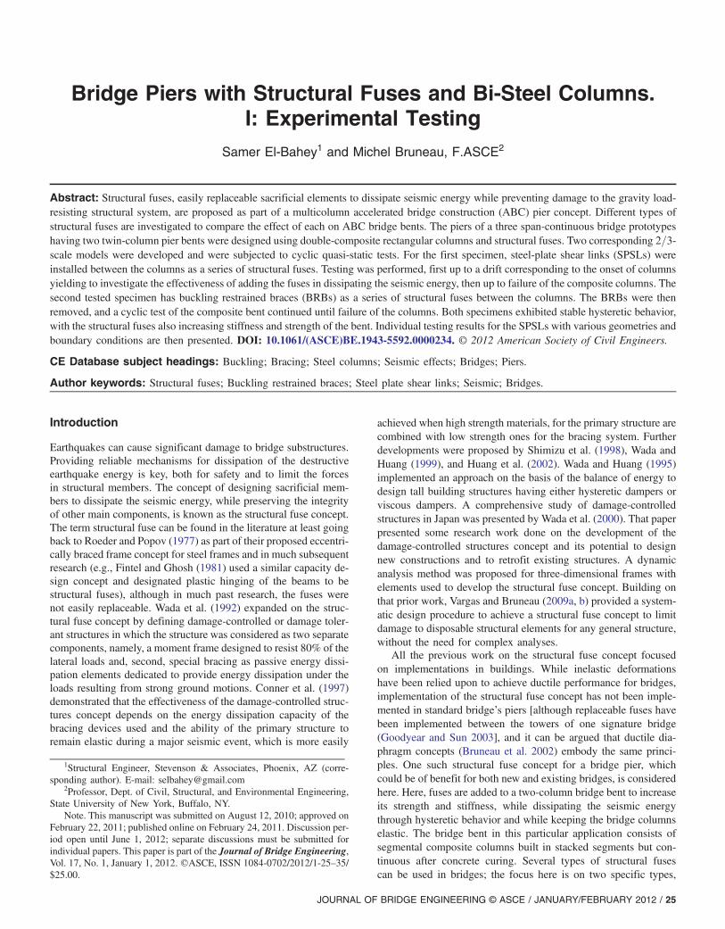
Hysteretic plots of specimen base shear versus top displacement areshown in Fig. 5 for specimens S1, S2-1, and S2-2. Fig. 6 showsspecimens S1, S2-1, and S2-2 prior to testing.
Specimen (S1)
Testing of specimen S1 proceeded in three steps because of unex-pected failures in the full penetration welded splices connecting thecolumns’ segments. In the first part of the test, the specimen re-mained elastic up to a displacement equal to 25 mm (0.36% drift).At 50 mm displacement (0.72% drift), the lateral load resisted bythe specimen dropped by 80% from 613 kN to 129 kN. This wasbecause of an unexpected weld failure in the column segment con-nection in the lower end of the east column.An investigation was conducted to understand the cause of the
failure, and a decision was made to repair/reinforce both lower spli-ces of the specimen (the fractured and unfractured ones) by adding
a 16 mm thick, 50 mm wide steel plate to create a new fillet-weldedsplice all around the columns on top of the existing splice locations.These new splices were generously overdesigned to preclude anyfurther failures at those locations. Reasons for these brittle failuresare briefly explained later.Also, a decision was made to take out the buckling restraints
attached to the SPSLs, because at that time, the cause for the in-correctly predicted fuse yielding could not be explained; the intentwas to make sure that the fuses would yield before the columns, andsince deformation of the fuses was not visible because of the pres-ence of the restraints, it was judged prudent to remove them for thenext phase of testing. Taking out the restraints decreases the con-tribution of the links to the total strength of the system because theywill buckle and behave more like a steel-plate shear wall with per-forations as explained in the companion paper (El-Bahey andBruneau 2011). The ability to develop structural fuses nonethelessremained.Since the specimen was almost completely elastic at the time of
the weld failure, the testing protocol was restarted from the begin-ning. Removing the restraints did not affect the elastic stiffness ofthe total system; this is because of the fact that the unrestrainedSPSLs behave similarly to the restrained SPSLs in the elastic range,and differences start to occur only after the unrestrained SPSLs startto buckle (El-Bahey and Bruneau 2011). All the previously appliedcycles were reapplied with similarly observed elastic behavior (butwithout weld fracture this time). Testing continued with appliedlateral displacements beyond the one at which the connection splicefailure had previously occurred. At 37.5 mm displacement (0.54%drift), signs of yielding started to occur on the middle links. Theyield point of the fuses was experimentally defined as the onset ofsoftening that occurred on the hysteretic curve. Yielding had propa-gated to all links when 100 mm displacement (1.5% drift) wasreached. At 100 mm displacement (1.5% drift), the lateral load re-sisted by the specimen dropped by 41% from 887 kN to 507 kN.This was because of another unexpected weld fracture in the col-umn splice in the upper end of the west column.To better understand the cause of the recurring undesirable weld
performance, a more intensive investigation was conducted on thetype of welding material used and the actual yield strength of thesteel used for the bi-steel panels. It was discovered that the yieldingand fracture stress were approximately 40% more than expected,with yield strengths of 470 MPa, and 520 MPa, and ultimatestrengths of 530 MPa and 580 MPa, respectively. Matching electro-des were E70. A few weld defects (incomplete beveling and minorundercuts) also detrimentally affected behavior of these full pen-etration welds).The same repair/reinforcement detail as done previously for the
lower splices was implemented for both the upper splices of thespecimen (the fractured and unfractured ones) to create a newfillet-welded splice all around the columns on top of the existingsplice locations.Testing restarted by repeating the cycles at a displacement of
75 mm (1.1% drift). At 112.5 mm displacement (1.6% drift), minorsigns of yielding of the lower-west column were observed. At thatdrift, it was determined that the part of the experiment intended toillustrate the structural fuse concept had been completed because afurther increase in displacement would have resulted in the col-umns yielding. Fig. 7 shows the links at this stage of the test.Nevertheless, testing continued for the specific purpose of
observing the ultimate behavior of the bi-steel columns in this par-ticular application. Local buckling at the west side of the lower-west column started to appear at 150 mm displacement (2.2% drift)as shown in Fig. 8(a), while fracture started to occur at the samedrift level at the east side of the column and propagated rapidly.
28 / JOURNAL OF BRIDGE ENGINEERING © ASCE / JANUARY/FEBRUARY 2012
The column was completely fractured along its west side as shownin Fig. 8(b) at 187.5 mm displacement (2.7% drift), and the loaddropped from 700 kN to 420 kN at that point.The lower-east column started to locally buckle at 187.5 mm
displacement (2.7% drift). At that point, the west column was se-verely damaged, and, as far as observing further damage to thatcolumn, imposing further cycles of inelastic displacement to thatcolumn from that point onward was judged to be of no benefit.However, it was decided to continue testing monotonically, impos-ing compression on the west column and tension on the east column
until the east column was completely damaged. Testing continueduntil a displacement of 225 mm (3.3% drift). At that point, crushedconcrete started to come out of the fractured ends of the extensivelydamaged west column. Excessive buckling was observed on theeast column at that stage, accompanied by a minor fracture thatstarted to occur. It is shown in the pictures that the buckled shapeis affected by the presence of the bi-steel shear connector, whichappeared to be effective as a buckling restraint point. Unfortunately,the test ended when another unexpected sudden splice failure oc-curred, this time in the midheight splice of the west column at
Fig. 5. Specimen hysteresis: (a) S1; (b) S2-1; (c) S2-2
JOURNAL OF BRIDGE ENGINEERING © ASCE / JANUARY/FEBRUARY 2012 / 29

225 mm displacement (3.3% drift) to end that test. While someweld failure occurred during testing, it is believed that these failureswhere for that particular case. With due quality control of the weldsand steel properties, it is believed that these ABC systems are ef-fective, time saving, and economical.
Specimen (S2-1)
To avoid a repeat of the problems because of weld failures, all spli-ces of specimen S2-1 were reinforced prior to the test by addingsteel plates at the locations of all the welded splices betweenthe column segments (plates and weld sizes identical to those inthe prior specimen).Testing started following the same loading protocol. Specimen
S2-1 reached a displacement of 37.5 mm (0.54% drift) and exhib-ited completely linear behavior. At 50 mm displacement (0.72%drift), signs of yielding were observed by softening of the hystereticloop; this was attributed to the yielding of the BRBs, because nosign of yielding was observed in any of the columns. No strain ga-ges could be installed on the BRBs, so this yielding could only beinferred from the shape of the hysteretic loops.Up to 87.5 mm displacement (1.3% drift), no evidence of yield-
ing or buckling was observed in the column bases. At 100 mm dis-placement (1.45% drift), the first signs of minor local bucklingwere observed in the bottom-east column. At this point, testingwas terminated to preserve the integrity of the columns for a finaltest in which only the bare framewas to be tested (without any fusesbetween the columns) and was needed for comparison purposes.Fig. 9 shows the hysteretic behavior for one of the BRBs installed(third from top) plotted against the total system force. The yieldingof this particular BRB occurred at approximately 0.6 mm axialdisplacement, and an elongation of approximately 6 mm was
Fig. 6. Specimens prior to testing: (a) S1; (b) S2-1; (c) S2-2
Fig. 7. SPSL’s yielding at 1.6% drift
Fig. 8. (a) Local buckling of west column 2.2% drift; (b) fracture at 2.7% drift
30 / JOURNAL OF BRIDGE ENGINEERING © ASCE / JANUARY/FEBRUARY 2012

observed, from which an approximate ductility value of 8 is ob-served. The other BRBs exhibited different ductility values rangingfrom 3 to 17 depending on their location along the height of thecolumns (El-Bahey and Bruneau 2010). A small amount of slip-page occurred because of the pin connection of the BRBs.
Specimen (S2-2)
To quantify the contribution of the fuses to the strength and stiff-ness of the total system, bare frame testing was essential. After ter-minating testing on specimen S2-1, the BRBs were removed.A second objective of this test was to investigate the cyclic
behavior of the bi-steel columns. Toward this end, the bare framewas subjected to cycles of progressively increasing lateral displace-ment magnitudes until failure of the columns occurred. Linearbehavior was observed, as confirmed by the hysteretic curve shownin Fig. 5(c) and also by the average strains read from the gages atthe bottom of the columns up to 100 mm displacement (1.45%drift) where signs of local buckling were observed at the east sideof the bottom-east column. At 100 mm displacement (1.45% drift),buckling propagated to the north side of the bottom-east column.At 125 mm displacement (1.81% drift), a minor crack of ap-
proximately 12.5 mm was observed in the northeast and southeastcorners, weld of the bottom-east column. Because of the concernthat this might be an isolated weld defect that could lead to unrep-resentative response, a decision was made to fix the welds beforetesting continued. Fixing the welds was done by adding three weldpasses of approximately 125 mm on top of the existing weld at thespecific fracture location. At 150 mm displacement (2.17% drift),local buckling started to develop on the west side of the bottom-west column. A minor crack on the same face of the columnwas observed at the connection between the plate and the internalshear connectors. Another crack reappeared on top of the weld
reinforcement at 150 mm displacement (2.17% drift). At 150 mmdisplacement (2.17% drift), a similar crack was observed on theeast side of the bottom-east column. At the same time, a huge crackat the southeast corner of the east column was observed, and con-crete started spalling out of the column.Testing continued to 175 mm displacement (2.5% drift), at
which the lateral load resisted by the specimen dropped 44% from711 kN to 400 kN. As testing continued, to better understand theprogression of the failure mechanism (and because the specimenhad a nonnegligible residual strength), the crack propagated acrossthe south side of the east column, and the east column was totallydamaged at this stage.It was not deemed beneficial to cycle further beyond that point,
but the west column was still intact, having suffered only from localbuckling. So it was decided to apply one more half cycle up to adisplacement that would make the west column totally fails. Thefractured column would be in compression during that half cycle,making that last stage of testing possible. At 175 mm displacement(2.5% drift), a minor crack started to appear at the northwest cornerof the bottom-west column. The crack started to grow and propa-gate as displacement was increased in the same direction. At thesame time, the east column was suffering major damage at 200 mmdisplacement (2.9% drift). At 225 mm displacement (3.26% drift),the crack at the northwest corner of the west column propagated,and concrete started spalling from the southeast corner of the eastcolumn. At 250 mm displacement (3.62% drift), the applied loadstarted to drop gradually as shown on the hysteretic curve, and theexisting crack on the west face of the west column further propa-gated. At the same time, another large crack developed at thenortheast corner of the bottom-east column, and concrete rubblestarted to escape from the crack opening as shown in Fig. 10(a).At 300 mm displacement (4.35% drift), the west column had de-veloped 600 mm long cracking along its base and had extensivelocal buckling, and concrete rubble started escaping from the north-west corner crack as shown in Fig. 10(b). Testing was then termi-nated at that stage.
Comparison of Results
Average strains for column sides at the onset of column yielding(1.6% drift) are shown in Fig. 11. Specimens S1 and S2-1 respec-tively, showed that no significant yielding has occurred in thecolumns, and the hysteretic behavior is due to the fuses yielding.A comparison for the values of the elastic stiffness, base shear, duc-tility, drift, and strength reduction for each specimen is shown in
Fig. 9. Hysteretic behavior for BRB (third from top)
Fig. 10. (a) Damage at east column at 3.62% drift; (b) damage at west column at 4.35% drift
JOURNAL OF BRIDGE ENGINEERING © ASCE / JANUARY/FEBRUARY 2012 / 31

Table 1. Specimen S1 performed successfully after unexpected fail-ures and repairs of the welded splices between the segmental col-umns. After fixing the welds, the specimen behaved in a stableductile manner until it reached 225 mm displacement (3.3% drift).The onset of column yielding was observed at 100 mm displace-ment (1.6% drift) accompanied with minor local buckling at thebottom of one column. A base shear of 875 kN was observed atthat level of drift. Failure of the specimen was due to a fractureat the bottom of both columns because of low cycle fatigue, whichdeveloped at the locations of repeated local buckling. A strengthreduction of 33% from the peak value was observed at the maxi-mum drift reached when testing had to stop because of the failure ofa midheight column splice (this failure could not be repaired). Add-ing the SPSLs increased the elastic stiffness of the bare frame by80%, while the strength increased by 31%. This strength increasewas less than originally expected from the SPSLs because of theremoval of the buckling restraints, which decreased the SPSLsstrength by 30%.Specimen S2-1 was also successfully tested up to a drift corre-
sponding to the onset of column yielding at 100 mm displacement
(1.6% drift); a base shear of 881 kN was observed at that level ofdrift. As indicated previously, because it was essential to keep theintegrity of the column for testing the bare frame alone, testingstopped after minor signs of local buckling were observed onone of the columns. No failure was expected from this specimen,but yielding of the BRBs dissipating the seismic energy was ob-served on the overall hysteretic behavior of the specimen. Addingthe BRBs increased the elastic stiffness of the bare frame by 80%,while the strength increased by 20%.Specimen S2-2 was tested successfully to 175 mm displacement
(2.5% drift) until the east column failed. Noncyclic testing contin-ued in the other direction up to a displacement of 300 mm (4.45%drift) to fail the other column. Fracture occurred at the bottom ofboth columns because of low cycle fatigue, which developed at thelocations of repeated local buckling. It is shown in Table 1 that allspecimens did not reach the setup design strength of 1,250 kN; thisis because this strength was designed taking into account the pres-ence of out-of-plane restraints for the SPSLs (which were removedat a previous testing stage).
Fig. 11. Average strains of column sides for Specimens S1 and S2-1
Table 1. Summary of Peak Results
Specimen
Elasticstiffness(kN=mm)
Base shear atcolumnyielding(kN)
Maximumbase shear(kN)
Fuseductilityat columnyielding
Fuseductility
at maximumdrift
Columnyieldingdrift (%)
Maximumdrift (%)
Strengthreductionat maximumdrift (%)
S1 19 875 982 4 8 1.6 3.3 33
S2-1 21.5 881 — 4 — 1.6 — —S2-2 8 666 806 — — 1.6 4.3 29
32 / JOURNAL OF BRIDGE ENGINEERING © ASCE / JANUARY/FEBRUARY 2012
Experimental Testing of Individual Fuses
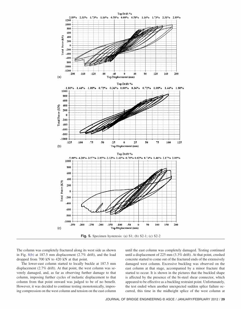
Several SPSLs having the same dimensions as the ones used in thebridge pier test were selected for individual quasi-static testing.Some having lateral restraints using a fiberglass building panelmaterial, and some are without lateral restraints to compare theirbehavior with the restrained ones and evaluate the amount ofstrength lost by the fuses after removing the restraints.The test setup shown in Fig. 12 was originally designed by
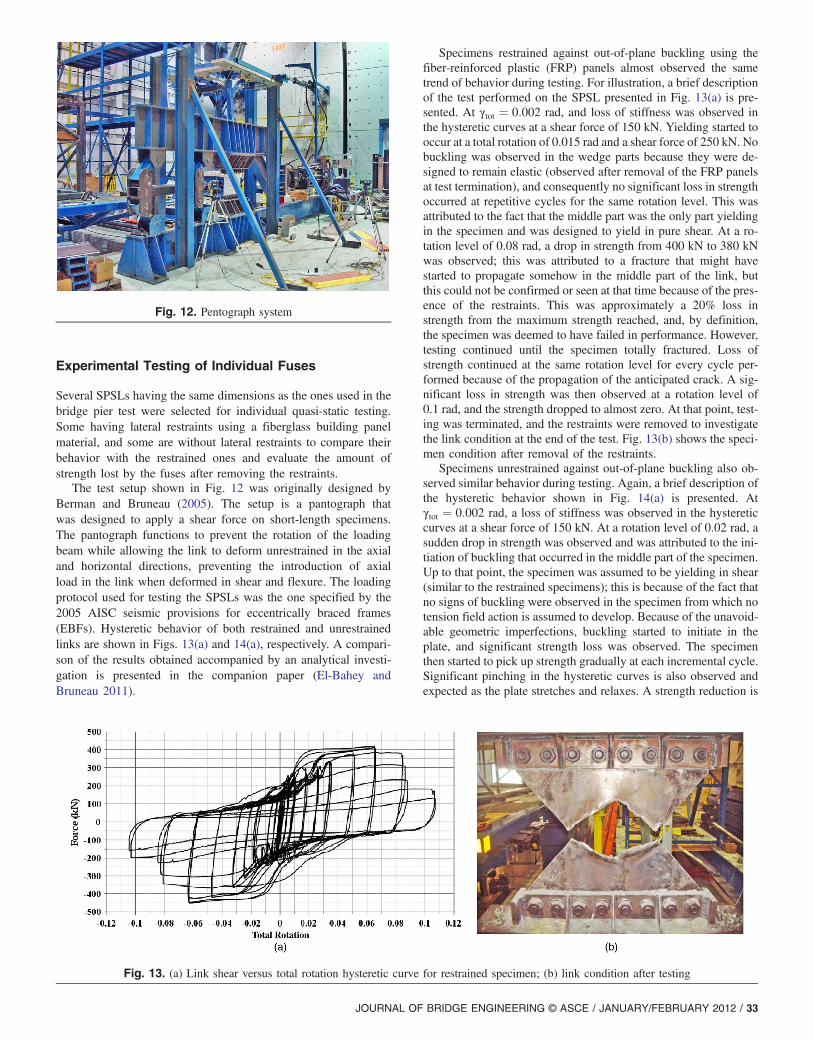
Berman and Bruneau (2005). The setup is a pantograph thatwas designed to apply a shear force on short-length specimens.The pantograph functions to prevent the rotation of the loadingbeam while allowing the link to deform unrestrained in the axialand horizontal directions, preventing the introduction of axialload in the link when deformed in shear and flexure. The loadingprotocol used for testing the SPSLs was the one specified by the2005 AISC seismic provisions for eccentrically braced frames(EBFs). Hysteretic behavior of both restrained and unrestrainedlinks are shown in Figs. 13(a) and 14(a), respectively. A compari-son of the results obtained accompanied by an analytical investi-gation is presented in the companion paper (El-Bahey andBruneau 2011).
Specimens restrained against out-of-plane buckling using thefiber-reinforced plastic (FRP) panels almost observed the sametrend of behavior during testing. For illustration, a brief descriptionof the test performed on the SPSL presented in Fig. 13(a) is pre-sented. At γtot ¼ 0:002 rad, and loss of stiffness was observed inthe hysteretic curves at a shear force of 150 kN. Yielding started tooccur at a total rotation of 0.015 rad and a shear force of 250 kN. Nobuckling was observed in the wedge parts because they were de-signed to remain elastic (observed after removal of the FRP panelsat test termination), and consequently no significant loss in strengthoccurred at repetitive cycles for the same rotation level. This wasattributed to the fact that the middle part was the only part yieldingin the specimen and was designed to yield in pure shear. At a ro-tation level of 0.08 rad, a drop in strength from 400 kN to 380 kNwas observed; this was attributed to a fracture that might havestarted to propagate somehow in the middle part of the link, butthis could not be confirmed or seen at that time because of the pres-ence of the restraints. This was approximately a 20% loss instrength from the maximum strength reached, and, by definition,the specimen was deemed to have failed in performance. However,testing continued until the specimen totally fractured. Loss ofstrength continued at the same rotation level for every cycle per-formed because of the propagation of the anticipated crack. A sig-nificant loss in strength was then observed at a rotation level of0.1 rad, and the strength dropped to almost zero. At that point, test-ing was terminated, and the restraints were removed to investigatethe link condition at the end of the test. Fig. 13(b) shows the speci-men condition after removal of the restraints.Specimens unrestrained against out-of-plane buckling also ob-
served similar behavior during testing. Again, a brief description ofthe hysteretic behavior shown in Fig. 14(a) is presented. Atγtot ¼ 0:002 rad, a loss of stiffness was observed in the hystereticcurves at a shear force of 150 kN. At a rotation level of 0.02 rad, asudden drop in strength was observed and was attributed to the ini-tiation of buckling that occurred in the middle part of the specimen.Up to that point, the specimen was assumed to be yielding in shear(similar to the restrained specimens); this is because of the fact thatno signs of buckling were observed in the specimen from which notension field action is assumed to develop. Because of the unavoid-able geometric imperfections, buckling started to initiate in theplate, and significant strength loss was observed. The specimenthen started to pick up strength gradually at each incremental cycle.Significant pinching in the hysteretic curves is also observed andexpected as the plate stretches and relaxes. A strength reduction is
Fig. 12. Pentograph system
Fig. 13. (a) Link shear versus total rotation hysteretic curve for restrained specimen; (b) link condition after testing
JOURNAL OF BRIDGE ENGINEERING © ASCE / JANUARY/FEBRUARY 2012 / 33
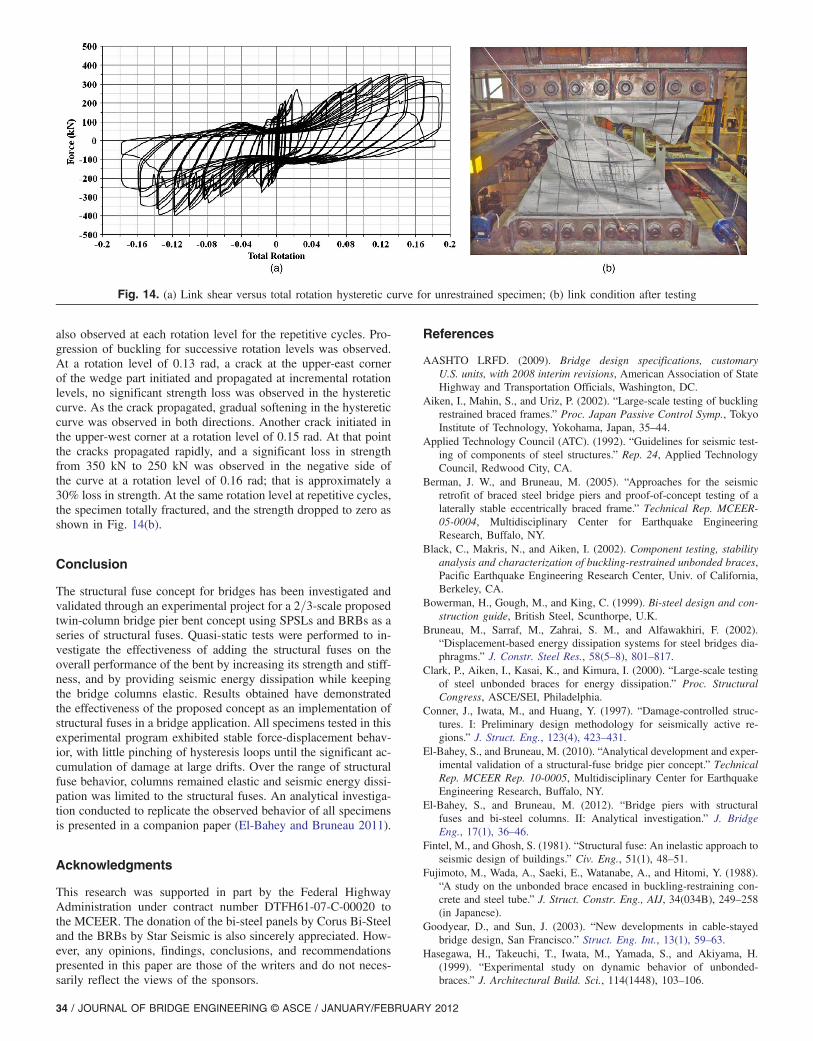
also observed at each rotation level for the repetitive cycles. Pro-gression of buckling for successive rotation levels was observed.At a rotation level of 0.13 rad, a crack at the upper-east cornerof the wedge part initiated and propagated at incremental rotationlevels, no significant strength loss was observed in the hystereticcurve. As the crack propagated, gradual softening in the hystereticcurve was observed in both directions. Another crack initiated inthe upper-west corner at a rotation level of 0.15 rad. At that pointthe cracks propagated rapidly, and a significant loss in strengthfrom 350 kN to 250 kN was observed in the negative side ofthe curve at a rotation level of 0.16 rad; that is approximately a30% loss in strength. At the same rotation level at repetitive cycles,the specimen totally fractured, and the strength dropped to zero asshown in Fig. 14(b).
Conclusion
The structural fuse concept for bridges has been investigated andvalidated through an experimental project for a 2=3-scale proposedtwin-column bridge pier bent concept using SPSLs and BRBs as aseries of structural fuses. Quasi-static tests were performed to in-vestigate the effectiveness of adding the structural fuses on theoverall performance of the bent by increasing its strength and stiff-ness, and by providing seismic energy dissipation while keepingthe bridge columns elastic. Results obtained have demonstratedthe effectiveness of the proposed concept as an implementation ofstructural fuses in a bridge application. All specimens tested in thisexperimental program exhibited stable force-displacement behav-ior, with little pinching of hysteresis loops until the significant ac-cumulation of damage at large drifts. Over the range of structuralfuse behavior, columns remained elastic and seismic energy dissi-pation was limited to the structural fuses. An analytical investiga-tion conducted to replicate the observed behavior of all specimensis presented in a companion paper (El-Bahey and Bruneau 2011).
Acknowledgments
This research was supported in part by the Federal HighwayAdministration under contract number DTFH61-07-C-00020 tothe MCEER. The donation of the bi-steel panels by Corus Bi-Steeland the BRBs by Star Seismic is also sincerely appreciated. How-ever, any opinions, findings, conclusions, and recommendationspresented in this paper are those of the writers and do not neces-sarily reflect the views of the sponsors.
References
AASHTO LRFD. (2009). Bridge design specifications, customaryU.S. units, with 2008 interim revisions, American Association of StateHighway and Transportation Officials, Washington, DC.
Aiken, I., Mahin, S., and Uriz, P. (2002). “Large-scale testing of bucklingrestrained braced frames.” Proc. Japan Passive Control Symp., TokyoInstitute of Technology, Yokohama, Japan, 35–44.
Applied Technology Council (ATC). (1992). “Guidelines for seismic test-ing of components of steel structures.” Rep. 24, Applied TechnologyCouncil, Redwood City, CA.
Berman, J. W., and Bruneau, M. (2005). “Approaches for the seismicretrofit of braced steel bridge piers and proof-of-concept testing of alaterally stable eccentrically braced frame.” Technical Rep. MCEER-05-0004, Multidisciplinary Center for Earthquake EngineeringResearch, Buffalo, NY.
Black, C., Makris, N., and Aiken, I. (2002). Component testing, stabilityanalysis and characterization of buckling-restrained unbonded braces,Pacific Earthquake Engineering Research Center, Univ. of California,Berkeley, CA.
Bowerman, H., Gough, M., and King, C. (1999). Bi-steel design and con-struction guide, British Steel, Scunthorpe, U.K.
Bruneau, M., Sarraf, M., Zahrai, S. M., and Alfawakhiri, F. (2002).“Displacement-based energy dissipation systems for steel bridges dia-phragms.” J. Constr. Steel Res., 58(5–8), 801–817.
Clark, P., Aiken, I., Kasai, K., and Kimura, I. (2000). “Large-scale testingof steel unbonded braces for energy dissipation.” Proc. StructuralCongress, ASCE/SEI, Philadelphia.
Conner, J., Iwata, M., and Huang, Y. (1997). “Damage-controlled struc-tures. I: Preliminary design methodology for seismically active re-gions.” J. Struct. Eng., 123(4), 423–431.
El-Bahey, S., and Bruneau, M. (2010). “Analytical development and exper-imental validation of a structural-fuse bridge pier concept.” TechnicalRep. MCEER Rep. 10-0005, Multidisciplinary Center for EarthquakeEngineering Research, Buffalo, NY.
El-Bahey, S., and Bruneau, M. (2012). “Bridge piers with structuralfuses and bi-steel columns. II: Analytical investigation.” J. BridgeEng., 17(1), 36–46.
Fintel, M., and Ghosh, S. (1981). “Structural fuse: An inelastic approach toseismic design of buildings.” Civ. Eng., 51(1), 48–51.
Fujimoto, M., Wada, A., Saeki, E., Watanabe, A., and Hitomi, Y. (1988).“A study on the unbonded brace encased in buckling-restraining con-crete and steel tube.” J. Struct. Constr. Eng., AIJ, 34(034B), 249–258(in Japanese).
Goodyear, D., and Sun, J. (2003). “New developments in cable-stayedbridge design, San Francisco.” Struct. Eng. Int., 13(1), 59–63.
Hasegawa, H., Takeuchi, T., Iwata, M., Yamada, S., and Akiyama, H.(1999). “Experimental study on dynamic behavior of unbonded-braces.” J. Architectural Build. Sci., 114(1448), 103–106.
Fig. 14. (a) Link shear versus total rotation hysteretic curve for unrestrained specimen; (b) link condition after testing
34 / JOURNAL OF BRIDGE ENGINEERING © ASCE / JANUARY/FEBRUARY 2012

Huang, Y., Wada, A., Iwata, M., and Mahin, S. (2002). “Design of damage-controlled structures.” Innovative approaches to earthquake engineer-ing, WIT Press, Billerica, MA, 85–118.
Iwata, M., Kato, T., and Wada, A. (2000). “Buckling-restrained braces ashysteretic dampers.” Proc., Behavior of Steel Structures in SeismicAreas STESSA 2000, Balkema, Rotterdam, Netherlands, 33–38.
Lopez, W., Gwie, D., Saunders, M., and Lauck, T. (2002). “Lessons learnedfrom large-scale tests of unbonded braced frame subassemblage.”Proc., 71st Annual Convention, Structural Engineers Association ofCalifornia, Sacramento, CA, 171–183.
López, W., and Sabelli, R. (2004). “Seismic design of buckling-restrainedbraced frames.” ⟨http://www.steeltips.org/steeltips/tip_details.php?id=76⟩ (2011).
Mamoru Iwata, M. M. (2006). “Buckling-restrained brace using steel mor-tar planks; performance evaluation as a hysteretic damper.” EarthquakeEng. Struct. Dyn., 35(14), 1807–1826.
Reina, P., and Normile, D. (1997). “Fully braced for seismic survival.” Eng.News-Rec., 34–36.
Roeder, C., and Popov, E. (1977). “Inelastic behavior of eccentric bracedsteel frames under cyclic loadings.” Rep. No. UCB-77/17, EarthquakeEngineering Research Center, Univ. of California, Berkeley, CA.
Sabelli, R., Mahin, S., and Chang, C. (2003). “Seismic demands on steelbraced frame buildings with buckling-restrained braces.” Eng. Struct.,25(5), 655–666.
Saeki, E., Maeda, Y., Nakamura, H., Midorikawa, M., andWada, A. (1995).“Experimental study on practical-scale unbonded braces.” J. Struct.
Constr. Eng., AIJ, 476, 111–120 (in Japanese).Shimizu, K., Hashimoto, J., Kawai, H., and Wada, A. (1998). “Applicationof damage control structure using energy absorption panel.” StructuralEngineering World Wide, Paper No. T105-2, Elsevier Science,Amsterdam, Netherlands.
Vargas, R., and Bruneau, M. (2009a). “Analytical response and design ofbuildings with metallic structural fuses. I.” J. Struct. Eng., 135(4),386–393.
Vargas, R., and Bruneau, M. (2009b). “Experimental response of buildingsdesigned with metallic structural fuses. II.” J. Struct. Eng., 135(4),394–403.
Wada, A., Connor, J. J., Kawai, H., Iwata, M., and Watanabe, A. (1992).“Damage tolerant structures.” Proc., Fifth U.S.–Japan Workshop on theImprovement of Structural Design and Construction Practices, ATC-15-4, Applied Council Technology, Redwood City, CA, 27–39.
Wada, A., and Huang, Y. (1995). “Preliminary seismic design of damagetolerant tall building structures.” Proc., Symp. on a New Direction inSeismic Design, Architectural Institute of Japan, Tokyo, 77–93.
Wada, A., and Huang, Y. (1999). “Damage-controlled structures in Japan.”Proc., U.S-Japan Workshop on Performance-Based EarthquakeEngineering Methodology for Reinforced Concrete Building Structures,Vol. 10, Pacific Earthquake Engineering Research Center, Univ. ofCalifornia, Berkeley, CA, 279–289.
Wada, A., Huang, Y., and Iwata, M. (2000). “Passive damping technologyfor buildings in Japan.” Prog. Struct. Eng. Mater., 2(3), 335–350.
JOURNAL OF BRIDGE ENGINEERING © ASCE / JANUARY/FEBRUARY 2012 / 35