BRIDGE PESIGN AIDS DECEMBER 1987 1 0-1 - Caltrans · Medians on multilane divided highways shall be...
43
BRIDGE PESIGN AIDS DECEMBER 1987 1 0-1 General Feat u res of Design Determination of Waterway Area. Restricted Waterwqys. Channel Openings All information needed by the designer relative to the above three subjects will be set forth in the Preliminary Report. Size of Culvert Openings See "Culvert Design," Highway Design Manual. Length of Culverts See "Physical Standards for Culverts," Highway Design Manual. Strucrural Design of Culverts The Office of Structure Design shall be responsible for the Structural adequacy of all drainage structures. Standard Box Culvert sheets are available for a large range, 4' to 14' span, of single and multiple box culverts. A standard Arch Culvert sheet is available for arches ranging in size from 6' to 22' span. Structural fill height tables are also available for corrugated metal pipe, structural plate pipe and reinforced concrete pipe. Special designs of any drainage structure are to be prepared or reviewed by the Office of Structure Design to assure structural adequacy. All information needed for the structural design of special culverts (i.e., those outside the range of size and load capacity available in standard corrugated metal pipe and reinforced concrete not covered by the Standard Box or Arch Culve rt sheets) will be furnished by the Districts. Bridge Roadbed 1. Wi dth The width of bridge roadbed shall be measured normal to the centerline between the bottoms of curbs or if curbs are not used. the clear width shall be the minimum measured between the nearest faces of the bridge railing or barrier. The width of bridges shall be as outlined by page 1 0·8 of this manual, Memo to Designers 14·2, and Topic 208 of the Highway Design Manual and in agreement with the geometric plan approved by the District Reviewer.
Transcript of BRIDGE PESIGN AIDS DECEMBER 1987 1 0-1 - Caltrans · Medians on multilane divided highways shall be...

BRIDGE PESIGN AIDS DECEMBER 1987 1 0-1
General Features of Design
Determination of Waterway Area Restricted Waterwqys Channel Openings
All information needed by the designer relative to the above three subjects will be set forth in the Preliminary Report
Size of Culvert Openings
See Culvert Design Highway Design Manual
Length of Culverts
See Physical Standards for Culverts Highway Design Manual
Strucrural Design of Culverts
The Office of Structure Design shall be responsible for the Structural adequacy of all drainage structures
Standard Box Culvert sheets are available for a large range 4 to 14 span of single and multiple box culverts A standard Arch Culvert sheet is available for arches ranging in size from 6 to 22 span Structural fill height tables are also available for corrugated metal pipe structural plate pipe and reinforced concrete pipe
Special designs of any drainage structure are to be prepared or reviewed by the Office of Structure Design to assure structural adequacy All information needed for the structural design of special culverts (ie those outside the range of size and load capacity available in standard corrugated metal pipe and reinforced concrete not covered by the Standard Box or Arch Culvert sheets) will be furnished by the Districts
Bridge Roadbed
1 Width
The width of bridge roadbed shall be measured normal to the centerline between the bottoms of curbs or if curbs are not used the clear width shall be the minimum measured between the nearest faces of the bridge railing or barrier
The width of bridges shall be as outlined by page 1 0middot8 of this manual Memo to Designers 14middot2 and Topic 208 of the Highway Design Manual and in agreement with the geometric plan approved by the District Reviewer
BRIDGE DESIGN AIDS PECEMBER 1987 1 0-2
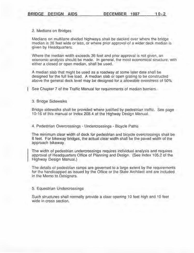
2 Medians on Bridges
Medians on multilane divided highways shall be decked over where the bridge median is 36 feet wide or less or where prior approval of a wider deck median is given by Headquarters
Where the median width exceeds 36 feet and prior approval is not given an economic analysis should be made In general the most economical structure with either a closed or open median shall be used
A median slab that might be used as a roadway at some later date shall be designed lor the full live load A median slab or open grating to be constructed above the general deck level may be designed for a allowable overstress of 50
See Chapter 7 of the Traffic Manual for requirements of median barriers
3 Bridge Sidewalks
Bridge sidewalks shall be provided where justified by pedestrian traffic See page 1 0-16 of this manual or Index 2084 of the Highway Design Manual
4 Pedestrian Overcrossings - Undercrossings - Bicycle Paths
The minimum clear width of deck for pedestrian and bicycle overcrossings shall be 8 feet For bikeway bridges the actual clear width shall be the paved width of the approach bikeway
The width of pedestrian undercrossings requires individual analysis and requires approval of Headquarters Office of Planning and Design (See Index 1052 of the Highway Design Manual)
The details of pedestrian ramps are governed to a large extent by the requirements for the handicapped as issued by the Office or the State Architect and are included in the Memo to Designers
5 Equestrian Undercrossings
Such structures shall normally provide a clear opening 10 feet high and 10 feet wide in cross section
Bridge Design Aids - April 1993 bull
Clearance At Structures
A Bridge Columns Abutments Retaining Walls and Barriers
1 Horizontal Clearance The horizontal clearance to bridge columns abutments retaining walls and barriers for freeways and expressways shall be dete1mined upon the basis ofengineering judgmentwith the objective ofeliminating fixed objects from near the edgeofshoulder wherever economishycally feasible A horizontal clearance of 30 feet or more from the edge of the traveled way is desirable Lesser clearances may be used where span length median width or other controls make the desired clearance unreasonable
The following are minimum horizontal clearance standards for bridge columns abutments retaining walls and barriers which in the case of freeways and expressways may be used only under very restricted conditions upon individual analysis and with Headquarters approval Additional horizontal clearance shall be provided where necessary to meet sigh t distance requirements
Clearances are measured from the edge of the traveled way
a) Two-lane Stare Highways - 10 feet minimum on each side
b) Multi-ltme Divided Highways- For the through roadbed on divided highways and for freeway facilities including the through roadbed auxiliary hmes ramps and collector roads the minimum cleanmce to the left of traffic shall be 9 feet On the right side the minimum clearance shall be 11 feet In the case ofextensive wa lls I 0 feet may be used on the right and 8 feet may be used on the left of traffic
c) Other Roads and Fromage Roads - On all other roads including frontage roads the minimum clearances to the face of the bridge columns abu tments reta ining walls and other obstructions shall be as follows
bull Two-way traffic 6 feet minimum on each side bull One-way traffic 42 feet minimum on the left and 6 feet minimum on the right in
the direction of traffic
Theelevation in Figure 10-3 on page 10-11 illustrates the requ ired distances from edge of traveled way to face of columns abutments walls and other obstructions Barriershymounted walls shall meet the clearance requirement for bridge barriers
Clearance at Structures --------------------- Page 10middot3
___Bridge Design Aids - April 1993 bull
2 Vertical Clearance
Freeway and Expressway - The minimum vertical clearance shall be 161h feet over Lhe entire width of traveled way and shoulders on the through facility speed change lanes ramps and collector roads on all pans of the freeway and expressway system Exceptions to this may apply when s tandard or existing rou tes having lower clearances make the higher standard impractica l or where due to unus ual conditions the cost of the higher standard becomes e xcessive in such cases the minimum vertical clearance shall be 15 feet over the ultimate traveled way and 14 feet above the ultimate shoulders
Non-Freeway or ExpresswltlY- The minimum vertical clearance at all other structures shall be 15 feet over the ultimate traveled way and 14 feet above the ultimate shoulders
Pedestrian Overcossings- The vertical clearance for pedestrian overcrossingsshall be2 feet greater than the vertical clearance provided for major slructures on the portion of highway involved If a pedestrian overcrossing is protected by a major structure a clearance greater tJ1an that of the major structure need not be provided
Sign Strucwres- All s ign structures shall have a vertical clearance of 18 feet
B Highway Clearance In Tunnels
Tunnel construction is so infrequent and costly that the width should be considered on an individual basis
Normally the minimum horizontal clearance on high volume freeways in urban areas shall include the full roadbed width of the approaches
In one-way tunnels on low volume freeways freeways in rural areas and on conventional highways the minimum side clearance from the edge of the traveled way s hall be 4hfeet on the le ft and 6 feet on the right For two-way tunnels this clearance shall be 6 feet on each side
T he minimum vertical clearanceshall be 15 feet measured atany point overthe traveled way and 14 feet above the lip of the gutter The vertical clearance shall be 16h feet on those routes selected for this clearance
C Clearance for Railroads
1 Railroad Tracks Minimum clearances both horizontal and vertical for structures over or adjacent to railroad tracks arc established by the Public Utilities Commission of the State of Califomia and are
Page 10middot4 Clearance at Structures
bullbullbullbullbullbullbullbullbullbullbull Bridge Design Aids - April1993 bull
set forth in their General Order No 26-D effective February l 1948 and in subsequent orders This minimum venical clearance over railroad tracks as required by General Order No 26-D and subsequent orders for aU new construction shall be 22 fcct6 inches except for electric railways carrying passengers only and unless otherwise specifically directed The Office of Structure Design is to increase this minimum vertical clearance by 6 inches to provide for future minor changes in track grades The minimum vertical clearance shown on the plans shall be 23 feet 0 inches
Horizontal clearances shall be as outlined on this page and as shown in Memo to Designers 17-105 and 17- 115
All curbs including median curbs shall be designed with 10 feet minimum clearance from the track centerline measured normal thereto
It should be noted that collision walls may be required for the clearances given on page 2 of Memo to Designers 17-l 05 Usually no collision walls are required if theclearance is 10 feet or more on tangent track and 1 l feet or more on curved track
2 Off-Track Maintenance Equipment Eighteen foot horizontal c learance from centerline of track is required for sections of railroad where the railroad company is using or definitely plans to use off-track maintenance equipment This clearance is provided on one side of the railroad tracks the railroad company will specify on which side
3 Approval of Railroad Clearances AU plans involving railroad clearances shall be submined to the railroad for approval Such clearances are al~o subject to approval by the Public Utilities Commission
D Falsework Use
In many ca~es it is necessary to have falscwork over traffic during construction in order to have support-free open area beneath the permanent structure The elimination of permanent obstrucshyLions usually outweighs objecLions to the temporary inconvenience of falsework during construction
The minimum width of traffic opening through falsework for various lane and shoulder requiremenL~ is shown on Table 10-1
Clearance at Structures Page 10-5
Bridge Design Aids - April 1993 bull
Table 10-1 Falsework Span Requirements
Facility To Be Spanned Minimum Width of Opening Width Provides For Traffic Opening
25 1 Lane + 8 amp 5 Shoulders
37 2 Lane + 8 amp 5 Shoulders Freeway
49 3 Lane + 8 amp 5 Shoulders
61 4 Lane + 8 amp 5 Shoulders
20 1 Lane + 2- 4 Shoulders
32 2 Lane + 2- 4 Shoulders
Non-Freeway 40 2 Lane + 2 - 8 Shoulders
52 3 Lane + 2- 8 Shoulders
64 4 Lane + 2- 8 Shoulders
20 (2) 1 Lane + 2- 4 Shoulders Special Roadway (1)
32 (2) 2 Lane + 2 - 4 Shoulders
NOTES (1) Uses such as fire utility access or quasi public roads with very light traffic (2) No temporary railing provided
When temporary K railings are used to protect the falsework space must be provided for a two-foot deflection in the railing Other folTls of protection are ava ilable which may require less space for deflection
In special cases where existing restraints make it impractical to comply with the minimum widths of traffic openings set forth in the table above a lesser width may be approved by the Chief of the Office of Project Planning and Design
The minimum temporary vertical clearance over freeways shall be 15 feet 0 inches with the following exceptions Minimum temporary venical clearances of J4 feet 6 inches may be used over freeways for bridge widenings or other special cases when approved by the Chief of the Office of Project Planning and Design
In the case of falsework over conventional highways or streets careful consideration may be given to the use of vertical clearance of 14 feet 0 inches where falsework clearances control the grade line and where trucks may be diverted Substantial savings are possible with a lower grade line In choosing between 14 feet 0 inches and 15 feet 0 inches clearance each case shall be considered on its merits Careful attention shall be given to the relative cost of the higher clearance as compared with the cost of adequate traffic control by advance warning devices the
Page 10middot6 Clearance at Structures
I ~~ bullbullbullbullbullbullbullbullbullbullbull Bridge Design Aids - April1993 bull
nature volume and speed of traffic the safety of traffic the effect of an increase in vertical clearance on the grades ofother sections of roadway the feasibility ofclosing the local street to all traffic during construction or closing the local street to all truck traffic hut leaving it open to automobiles the use of detours the feasibility ofcanmiddotying local traffic through construction on subgrade or lowering the existing facili ty temporarily or permanently Over height buses in use in Los Angeles and San Francisco areas may anect vertical clearancerequircmcnts Applications for impaired falsework clearances should include a cost savings over the 15 feet 0 inches stmdard
Where the vertical falsework clearance is less then 15 feet advance warning devices shall be specified or shown on the plans Such devices may consist of Hashing lights overhead signs overheight detectors or a combination of these or other devices (Providing for these devices is usually the re~ponsibility of the District)
Toestablish the gradeofa structure to beconstructed with a falscwork opening allowance must be made for the depth of the falscwork The minimum falscwork depth required for a given traffic opening is dependent on the falscwork span and the superstructure depth Table I 0-1 lists the falsework opening widths required for various roadways Table 10middot2 on page 10-8 lists the falsework depths required for the openings shown in Table 10-1 Falsework depth requirements for traffic openings not listed in Table 10middot1 may be derived from Figure 10middot1 on page 10-9
Falscwork depths listed in Table I 0-2 and shown in Figure 10-1 are based on tangent structures which arc supported on falsework stringers placed parallel to the superstructure Structures which arc horizontally curved or arc skewed to the trdvelcd way being spanned frequently require falsework stringer placement perpendicular to the traveled way as depicted in Figure 10middot2 on page 10-10 When falscwork is constructed in this manner the point of minimum vertical clearance may be located at an exterior falscwork stringer outside the edge of deck of the structure
The Office of Structure Constmction should be consulted when there are questions about falsework depth requirements or when falscwork spans exceed 90 feet
Where vertical clearances either temporary or permanent arecriticalthe District and the Office of Structure Design shall work in close conjunction during the early design stage when the preliminary grades structure depths and falscwork depths can be adjusted without incurring major design changes
Clearance at Structures --------------------- Page 10middot7
___Bridge Design Aids - April 1993 bull
Table 10-2 Falsework Depth Requirements
Table 10middot2 is derived from the cuJVes in Figure 10middot1 on page 10middot9 and is a tabulation of the minimum falsework depth requirements for the specific traffic width openings included in Table 1 0middot1 Falsework Span Requirements The falseworllt depth values are based on optimum falsework stringer size selection for the various listed structure depths
Depth Of Superstructure
Facility to Minimum Width Up to 6 I Up to 8 I Upto10 I Up to 12
be Spanned of Traffic Opening Minimum Falsework Depth
25 1middot10h 2middot1 2-1 2middot81h
Freeway 37 2middot9 2middot111 3middot0 3t-3
49 3middot3 3middot3h 3middot3h 3-3
6t 3middot5 3middot5 3middot7 3middot71
20 1middot9 1middot10 1-10 1middot101
Non-Freeway 32 2-omiddot 2middot8h 2middot9 3middot0
40 3-omiddot 3-omiddot 3middot2h 3middot3
52 3middot3 3-31 3middot3h 3middot411
64 3middot5 3middot7h 3middot71h 3middot8
20 1-9 1middot10 1middot10 1middot10k
Soecial Roadwav 32 2middot0 2middot81 2middot9 3middot0
Because the width of traffic openings through falsework can significantly affect costs special care should be given to determine opening widths The following should be considered staging and traffic handling requirements the width of approach roadbed that will exist at the time the bridge is constructed traffic volumes desires of the local agencies controls in the form of existing facilities and the practical problems of falsework construction such as skew of roadway direction offa lsework stringers extension offalsework beneath existing deeper girder bridges etc
The placement and removal of falsework requires special consideration During these operashytions traffic shall either be stopped for short intervals or diverted away from the span where the placement or removal operations are being performed The method of traffic handling during these operations shall be included in th~ Special Provisions
Impaired clearances for falsework over railroads are permissible under special conditions but are subject to the rules and regulations of the Public Uti lities Commission of the State of California and the requirements of the operating railroad
Page 10-8 Clearance at Structures
Bridge Design Aids - April 1993 bull
400 ylt
~-==~~~~===~2~=z=375 middotmiddot- middot middotmiddot--middotmiddot- middotmiddotmiddotmiddotmiddotmiddotmiddotmiddotmiddotmiddotmiddotmiddotmiddot -r - middotmiddotmiddotmiddot middotmiddotmiddotmiddotmiddotmiddotmiddotmiddotmiddotmiddot---middotmiddotmiddotmiddotmiddotmiddotmiddotmiddot---middot- middotmiddotmiddotmiddotmiddotmiddot middotmiddotmiddotmiddotmiddotmiddotmiddotmiddotmiddotmiddotmiddotmiddotmiddotmiddotmiddotmiddotmiddotmiddotmiddotmiddotmiddotmiddotmiddotmiddot-middotmiddot-middotmiddotmiddotmiddotmiddotmiddot- - middotmiddotmiddot--middotmiddotmiddotmiddotmiddotmiddotmiddotmiddotmiddot-middotmiddotmiddotmiddot
====~~~~~r~=~=~~~==~==~350 middot-middotmiddot--middotmiddot-middotmiddotmiddotmiddotmiddotmiddotmiddotmiddotmiddotmiddot---middotmiddotmiddot-middotmiddot-middotmiddotmiddotmiddotmiddotmiddotmiddotmiddotmiddotmiddotmiddotmiddotmiddotmiddot-middotmiddotmiddotmiddotmiddotmiddot-middotmiddotmiddotmiddotmiddotmiddotmiddotmiddotmiddot---middot-middot-middot ~------___ Q
If 325 ~~~~=~~~~=-middot-====~~~=== I
-1 3000 ~~~~~~~~~~~~=~~~3~~~~~~~~~~-~~e d~~~-=~~~~~=-=~~~~~~~j~~~Q) Ill 275 _____7 - - - _____Iii u - ~~====~~=~~==-0 250 s= ==~~=========~~=---== Q) a
-J~_~middotmiddot-middot-~_____=~~==middotmiddot~~~0 225
---J____ Up to 6 structure depth- middot-middot--- - ______ -middot---bullI~middot--middot-middotmiddot-middotmiddot-middotmiddotmiddotmiddotmiddot-middotmiddotmiddotmiddotmiddotmiddot--middotmiddot- ---middotmiddotmiddot-middot-middotmiddotmiddotmiddotmiddotmiddotmiddotmiddotmiddot- middotmiddotmiddotmiddotmiddot-middotmiddotmiddotmiddotmiddot-middotmiddotmiddotmiddotmiddotmiddotmiddot-middot---- middotmiddotmiddotmiddotmiddotmiddotmiddotmiddot-middot-middotmiddotmiddotmiddotmiddotmiddot-middotmiddot-middotmiddotshy
200 --rmiddot middotmiddotmiddotmiddotmiddotmiddot_ middotmiddotmiddotmiddot-middot---middotmiddotmiddotmiddotmiddotmiddotmiddotmiddot-middotmiddotmiddot-middotmiddot-middotmiddotmiddotmiddotmiddotmiddotmiddot-middotmiddotmiddotmiddotmiddotmiddotmiddotmiddotmiddotmiddotmiddotmiddotmiddotmiddot-middotmiddot-middot--middot---middot--middot- middot _ ________ __ _ middotmiddot-middotmiddotmiddot-middotmiddot- middot----middotmiddotmiddot-middotmiddot-middot------middot---middotmiddot-------shy____________________________________ ____________ r_____ _____________________________________________
175 ---middotmiddot---middotmiddotmiddot-middot---middotmiddotmiddotmiddot-----middot--middotmiddotmiddotmiddot-middotmiddotmiddotmiddotmiddotmiddot-middotmiddot-middotmiddot---middotmiddotmiddotmiddotmiddotmiddotmiddotmiddotmiddotmiddotmiddotmiddotmiddotmiddotmiddotmiddotmiddotmiddot-middotmiddot--middot---middot-middotmiddotmiddot-middotmiddot-middot-middot----middot-middotmiddot--middotmiddotmiddot-middotmiddot-middot-
20 30 40 50 60 70 80 90
Falsework Opening Width Between Temporary Rails- Feet
400 - ___- - middot-middot---middot--- _______--- - -z~-
375 - - _______=- _middotmiddot=middotmiddot=-middot-_ middot---middotmiddot--middot--middotmiddot-middotmiddot---middotmiddotmiddotmiddotmiddot-middotmiddotmiddot--middotmiddot--middot-middotmiddot-middotmiddotmiddot-middotmiddot-middot-----middotmiddot-- - --- middot--middotmiddot-middotmiddotmiddot---middotmiddotmiddot---middot--middot---middot-middot-middot _____________ middotmiddot_ middotmiddotmiddot-middotmiddotmiddotmiddotmiddotmiddot-middotmiddot- middot-middot-middotmiddotmiddot-middot-middot-middot middotmiddotmiddotmiddot--middotmiddotmiddot--middot-middot---- - ---middot middot middot - yt __ ________________ 350 __-__ _______ ___ _____
Q Q) ==~-==-middot--middotmiddotmiddotmiddotmiddot------middot-middot-middotmiddot-middotmiddotmiddot-L~=====~--~== u 325
-1 I
300 ===~~==~-t-~-~=~===~=====0 - middotmiddotmiddot--middot-middot-middot bullbull bullbullbull f---middotmiddot-----middot- middotmiddotmiddot-middotmiddot--middot---middot------middot-middotmiddotmiddot-middotmiddot-middot middot middotmiddotmiddotmiddotmiddot---middotmiddot-middot-middotmiddot middot-middotmiddotmiddotmiddotmiddotmiddot-middotmiddot-middot-middotmiddot Q) Ill middot-middotmiddotmiddotmiddotmiddotmiddot-middotmiddotmiddot i middotmiddotmiddot-middotmiddot middot middotmiddotmiddot-middotmiddotmiddotmiddot - middot-middotmiddotmiddot middot middot -middotmiddot-middotmiddotmiddotmiddotmiddotmiddotmiddot-middotmiddotmiddotmiddotmiddotmiddotmiddotmiddot- middotmiddotmiddotmiddotmiddot-middotmiddot-middot middot-middotmiddot-middotmiddot -middotmiddotmiddot-middotmiddotmiddot---middot-middotmiddot middotmiddotmiddot- -middot-middot-middotmiddotmiddotmiddotmiddotmiddotmiddotmiddotmiddot--middotmiddotmiddotmiddot -middotmiddot- middot
275 _- - bull_ U t 12 structure de th middot--middot-middot-middot-middot-----middot-middot-middotmiddot-middot-middot- shy-middot _L-- _ p 0 p --- - _________ ~ -0 middot~i~==~~= s= 250 -middot --middotmiddotmiddotmiddotmiddotmiddot~middot-middot-------middotmiddot middotmiddotmiddotmiddot-middot-middot-middotmiddot-middotmiddotmiddotmiddotmiddotmiddotmiddotmiddotmiddotmiddot-middotmiddot-middotmiddotmiddotmiddotmiddotmiddotmiddotmiddotmiddotmiddotmiddot-middot-middot-middotmiddotmiddot---middotmiddotmiddotmiddotmiddot--middotmiddotmiddotmiddotmiddot--middot-middotmiddotmiddotmiddotmiddot--middot-middotmiddotmiddot-middotmiddot--middotmiddot-middot-middotmiddot a 0 225 Q)
~1~=~~~-~~~~~r~~~~~~~~~~=~=~~=~~~~~i~~~==~==~~~~ 200 c========
middot-middotmiddot-middot-middot-middot-middotmiddotmiddotmiddotmiddotmiddot-middot-----------middotmiddotmiddotmiddotmiddotmiddotmiddotmiddotmiddotmiddot-middot-middot-middotmiddot-middotmiddotmiddot- middotmiddotmiddotmiddotmiddot-middot--middotmiddotmiddotmiddot--middot-middotmiddot-middotmiddot-middotmiddot--middotmiddotmiddot---middot-middotmiddotmiddotmiddotmiddot-middot-middot-middotmiddot 175
20 60 70 80 90
Falsework Opening Width Between Temporary Rails - Feet
Figure 10-1
Clearance at Structures Page 10middot9
Bridge Design Aids - April1993 bull
Falsework bent
New construction Skewed or cuoved structure
Falsework stringers perpendicular to traffic opening
Plan
I I I I I I I I I I I I I
Section A-A
~ Location of final minimum vertical clearance
Location of minimum temporary vertical c learance
Figure 10-2
Page 10-10 Clearance at Structures
f Fig 10-3 Minimum Clearances for Highway Structures
iil g 15middot0 l
I II ~
J 44-01 1 23middot0 1 no Med 16middot6 B -v bullan 16-6 Bf LJ I 2Wav 6 I~Guard Raa(typ) rm -- (
c 4W 1 1Way -Go LL gt lt gt lt gt ~
ltil
Traveled Shoulder ipoundJpoundl 111 IFreeway and lJ 19 J Traveled 1Aux j11 JJ9 I Rame 111 Freeway and Way A Interstate Hwys A A Way lMe A A A Interstate Hwys
Frontage Roads and Notes A To be used only where desiredclearances of 30 feet is unreasonable Non-Freeway Roads B Clearance at edge of shoulder
ELEVATION C Forclearancessee Memo to Designers 17middot105and 17middot115
When add~ional vertical clearance will add to the project costs the above minimum vertical clearances may be extended up to 05 foot When vertical clearance exceeds this tolerance Federal participation will be based on the minimum given
Standards for Bridge Shoulder Width (7)
Shoulder Width (Feet) Shoulder Width (Feet) Freeways and Expressways Conventional Highways tDLeft Right Left Right
c (6) cca 4 Lanes 5 10 a Multi-lane Divided 8
b 6 Lanes or more 10 (I) 10 b Multimiddotlane Undivided 8 0 CD
c Separate Roadways (2) 10 c Two lane CD
d Auxiliary Lanes 10 Design Yr Traffic ()
cemiddot e Fwy to Fwy Connections 5 10 (3) ADT under 400 4 (4) l
f Ramps 4 (4) 8 (S) ADT 400- 1 500 6 lgt ADT over 1 500 8 c
d Climbing Lanes 4 ()
-Notes I lt11 On 1middot3R projects 5 feet on 6-lanes and 8 feet on 6-lanes are acceptable (See Highway Design Manual Topic 3021) lgt
Clt21 Use a and b above (3) A single lane connection over 1 500 feet in length shall be widened to 2-lanes ~h 5 foot shoulders cl ltbullgt Minimum width on structure lttgtg lttgtltSgt A single lane ramp widened to 2middot1anes shall have Qn the 2middot1ane section) 2middotfoot shoulder in rural areas or 4middotfoot permissible in urban areas cgt- (6) Use 5 feet for 4middot1anes and 8 feet for 6 or more lanes -- (7) lane references are for total number in both directions I
BRIDGE DESIGN AIDS MARCH 1991
Curbs
1 Type H Curb
To be used for matching approach roadway curb
Sidewalk wldlh 5-0 minimum
Face of curb
6 or 8 Finished roadway surface
2 Match Existing Curbs
Curbs or sidewalks may be made to match those on existing adjacent streets or to conform to city or other standards if local authorities so request
3 Omit Curbs
Curbs shall be omitted from structures unless required for sidewalks or drainage
4 Highway Design Manual
Topic 209- Curbs and Gutters covers policy and procedures for curbs on highway facilities
10-12
bull
BRIDGE DESIGN AIDS FEBRUARY 1985 0-13
CONCRETE BARRIERS BARRIER RAILINGS (STRUCTURES)
General Policy
The purpose of structure barriers is to retain and redirect errant vehicles Special attention shall be given to barrier railing design on structures having heavy pedestrian traffic or located near schools
In general there are four classes of barrier or railings
(a) Vehicular barriers (b) Combination vehicular barriers and pedestrian rai~ings (c) Pedestrian railings (d) Bicycle railings
Listed below are the approved types of barriers and railings for use on bridqe structures including overcrossinqs bull
bull Concrete Barrier Types 25 and 26 are vehicular barriers designatedfor general use on structures The Bridge Approach Railing type and length is usually recommended by the Districts
The type of pedestrian railing andor combination thereof s hall be selected by the District and a recommendation included with the bridqe site data forwarded to the Office of Structures Design
On structures which are to be transferred to local jurisdictions and which do not cross over a State highway consideration may be qiven to use of local standards where such a reques t ia made by local authorities
Vehicular Barriers or Railings
CONCRETE SARRIER TYPE 25
This barrier is designated for general use It has functional vehicle redirection characteristics similar to the Concrete Sarrier Type SO
BARRIER RAILING TYPE 18 (metal tube)
This railing may be used in ~hose situations where a self- cleaninq deck is required It should not be used where drainage off the sides of the structure is a hindranc~ to anythinq beneath it
BRIDGE DESIGN AIDS FEBRUARY 1982 10- 14
Combination Railings (Vehicular and Pedestrian)
CONCRETE BARRIER TYPE 26
This is the barrier for general use when sidewalks are provided on a bridge which also carries vehicles It must be accompanied with a tubular handrailing or a fe nce-type railing
The standard sidewalk width is 5 however this width may be varied as circums tances require
CHAIN LINK RAILING TYPE 7
This is the fence-type railing for general use with Concrete Barrier Type 26 to prevent objec ts from being thrown to the roadway below When a sidewalk (Type 26 barrier) is provided on one side of a bridge and Type 25 barrier on the other side Type 7 railing may be placed on the top of the Type 25 as additional protection from thrown objects Consideration should be given to the effect of the Type 7 railing on sight distance at the bridge ends and view ove r the side of the bridge
CHAIN LINK RAILING TYPE 6
This railing may be used in lieu of Type 7 when special architectural treatment is required
TUBULAR HAND RAILING
This railing is used with Type 26 (or Type 25) to increase the combined rail height for the safety of pedestrians It should be used in lieu of Type 7 where obj ect throwing will not be a problem or at ends of bridges to increase sight distance if fence-type railing would restrict sight distance
Pedestrian Railings
CHAIN LINK RAILING TYPE 3
This railing is used on pedestrian structures to prevent objects from being thrown to the roadway below
CHAIN LINK RAILING TYPE 7 (Modified)
This railing is similar to Type 7 except that it is mounted on the structure at the sidewalk level
CHAIN LINK RAILING (Six-foot)
This railing is not as high as Type 3 or 7 (Modified) and therefore its use is restricted to those locations where object
BRIDGE DESIGN AIDS FEBRUARY 1982 10-15
throwing will not be a problem (i e the ramp portion of pedestrian overcrossing when the ramp is not parallel to any roadway below)
Bicycle Railings
The minimum height of bicycle rail is 4 6 above the deck surface Therefore any of the combination railings or the chain link railings are satisfactory for bicycle rails Bicycles are not considered to operate on the walking surface of a sidewalk
BR IDGE DES IGN AIDS FEBRUJgtRY 1982 10- 1 6
COMBINATION RAILINGS FOR BRIDGE STRUCTURES (VEHICLE a PEDESTRIAN)
V- LINK RAILING TYPE 7
TYPE 26 WITH TYPE 7
= -
= middot- - N
HA IN LIN K RAIL ING
CHAIN LINK RAILING TYPE 6
= 0
- - 0
-CD
TYPE 26 WITH TYPE 6
tondord
TYPE 26 WITH TUBULAR HAND RAILING
CONCRETE BARRIER TYPE 25
I bull 4-o min 1 4- o min
TYPE 25 WITH TUBULAR RAILING TYPE 25
TYPE 25 WITH TYPE 7
BR IDGE DES IGN AIDS EERRUARY 1982 10 17
PEDESTRIAN RAILINGS FOR BRIDGE STRUCTURES
a-o~amiddot 3
CHAitl LltK RAILING TYPE 3 CHAIN LINK RAILING TYPE 7 (MODIFIED)
CHAIN LINK RAILING (6FT)
BRIDGE DESIGN AIDS FEBRUARY 1982 10- 18
ROADWAY DRAINAGE
The transverse drainage of roadways shall be secured by means of a suitable crown in the roadway surface and longitudinal drainage by camber or gradient If necessary longitudinal drainage shall be secured by means of scuppers inlets or other suitable means which shall be of sufficient size and number to drain the gutters adequately If drainage fixtures and downspouts are required the downspouts shall be of rigid corrosion-resistant material not less than six inches in least dimension provided with suitable cleanout fixtures The details of floor drains shall be such as to prevent the discharge of drainage water against any portion of the structure Overhanging portions of concrete decks preferably shall be provided with drip grooves
1 Roadway Drainage Details
Cross drainage of bridge decks is provided by crown or cross slope of the surface The crown is normally centered on the bridge except for one-way bridges where a cross slope in one direction is used The cross slope shall be the same as the approach pavement
Bridge deck drains shall not discharge on approach embankments or on other areas where harmful erosion may occur On railroad overheads and on highway separation structures of sufficient length to require deck drains it is usually necessary to install a system of longitudinal pipes below the deck slab to convey storm water to points where it may be discharged without damage to property below the structure Drainage facilities should be designed in such a manner that they will be as inconspicuous as practicable Drainage of bridge decks requires adequate grade Vertical curves on bridge decks should provide a minimum fall of oos foot per station This fall shall not extend over a length greater than 100 feet The flattest allowable tangent grade shall be 012 percent The flattest allowable tangent grade on long bridges whe re drainage is confined to the bridge deck shall be 025 percent
SUPERELEVATION
The superelevation of bridge decks shall be the same as that for highways The Highway Design Manual contains complete information on superelevation and superelevation transitions
Superelevation diagrams or grid sheets are incorporated in the Preliminary Report If this information is lacking or incomplete it will be supplied by the district on request
Transitions which fall on a structure sometimes cause an unsightly warp in the bridge railing If this happens it should be called to the attention of the district It may be possible to shift or alter the transition
BRIDGE DESIGN AIDS FEBRUARY 1 982 10-1 9
SURFACING ON BRIDGES
It is the policy of the Office of Structures Design to prov i de a concrete deck as the final riding surface on all new bridges Some requests have been received from Districts to provide asphaltic surfacing across an isolated short bridge A critical review should be made of all such requests Asphaltic surf acing is often required to match existing bridge surfacing material or to modif y the bridge cross slope on bridge widenings Modification of railing deck drains and expansion joint details should be considered with asphaltic surfacing
District requests to match the coloring of approach roadways may be accomplished with the applica tion of a slurry seal
Special surfacing and seals mdy be required in areas where salts are used to prevent icing
Contrast Treatment
See Topic 7-706 of the Highway Design Manual
UTILITIES
Where required provlslons shall be made for trolley wire supports and poles pillars for lights electric conduits telephone conduits water pipes gas pipes and sanitary sewers
ENCROACHMENTS ON BRIDGES
When required or when permitted provisions shall be made for the encroachment of public utility facilities on or near bridges
The District makes the fundamental decision to permit an encroachment in accordance with the Department of Transportations Policy on Encroachments in Highway Rights of Way
The District submits the information on proposed encroachments on or near bridges to the Office of Structures Design
During the design stage the bridge designer reviews the proposal for the following
1 Structural adequacy of the bridge for the weight and location of the facility
2 Compliance with the Encroachments on Bridges section of the policy on encroachments
3 Conflicts in construction sequence
BRIDGE DESIGN AIDS FEBRUARY 1982 10 20
The District and bridge designer should work in close conjunction with their Permit Engineers to avoid commitments that conflict with the encroachment policy The bridge PSampE should clearly show the utility work to be performed by the States contractor
The minimum information necessary on the plans consists of the name of the owner general description and the location of the facility openings and access openings (if required) In addition all hardware and material to be furnished andor installed by the State s contractor must be shown
The District prepares the encroachment permits at the completion of the PSampE Those involving bridges are submitted to the Office of Structures Maintenance for approval Upon approval the District issues the permits
During construction inspection of the work is performed from the plans specifications and the details of the permits
SPECIAL REQUIREMENTS FOR RAILROAD STRUCTURES
In almost all cases the agreement between the State and the railroad company for the construction of a railroad underpass (a structure carrying railroad tracks over a highway) provides that upon completion of construction the State will maintain the substructure (piers and abutments up to the bridge seats) and the railroad company will maintain the superstructure In view of their responsibility in connection with such maintenance the railroad companies have certain special requirements and preferences which must be observed in connection with the design and construction of underpass superstructures carrying their tracks These requirements are shown in Section 17 Memo to Designers
BRIDGE DESIGN AIDS FEBRUARY 1990 10-21
SELECTION OF TYPE
GENERAL
Structures designed by the Division ofStructures can be described by the principal type ofconstruction such as slab T-beam box girder steel girder etc Selection ofthe proper type for any given location is the responsibility of the Design Engineer subject to approval of the Design Supervisor The Project Designer prepares studies and makes reconunendations for structure type under the direction of the Design Engineer Economy safety and aesthetics aregenerally the controlling factors Selection may be based on other considerations as well such as
bull Deflection bull Maintenance cost bull Traffic convenience during construction bull Time for construction bull Construction worker safety bull Similarity to adjacent structures bull Superstructure depth and other preferences bull Substructure details bull Suitability for widening for ultimate construction bull Feasibility of falsework bull Passage of flood debris bull Seismicity at the site bull Commitments made to officials and individuals of the community
The structure selected for the site should be the type which best satisfies the traffic conditions and the environment in which it is located The importance of considering how traffic will be handled at a particular bridge site during the general plan stageofplan preparation cannot beoveremphasized Failure to give adequate thought to traffic handling early in project development can lead to situations in which safety is compromised to avoid major changes in completed plans Finding the least costly method of handling traffic safely through construction projects requires close cooperation and good communicashytion between d1c Districts and the Division ofStructures TI1e depth to span ratio shown for each structure type has proven to be workable and satisfactory for most ranges ofvariables in structure configurations with constant structure depth Variations from those ratios should be considered only for special cases at the advanced planning study stage
REPORT
After fully considering the above factors to determine the proper structure type the Project Engineer and Design Engineer are to discuss the architectural features with the Structures Aesthetics and Model Section For large or controversial projects discussions should also be held with District Design and Landscape personnel These may be individual or joint discussions as dictated by the size complexity and sociological economical ecological and environmental demands of the project
BRIDGE DESIGN AIDS FEBRUARY 1990 10-22
Through these discussions a sttucture with archi tectural features that are compatible with sttuctural safety and site requirements can be developed These discussions and resulting mutual agreements take place before the general plan is prepared
FonnDSD0045StructureTypeSelection shall becompleted to document the decisions made through this planning process A copy of Form DSD 0045 is on page 10-23 Under the Engineering and Architectural Summary heading enter a brief discussion or outline of factors which were considered in making the determination of structure type and related architectural features The color for steel bridges should also be entered under this heading The color selection should also be mutually satisfactory to the District and the Division ofStructures In the transmittal letter which accompanies the reduced prints to the Districts concurrence or comments should be requested for the recommended color Dates of meetings with other than Division of Structures personnel and ofvisits to the sites should be noted along with the participants names Visits to structure sites where the terrain is not changed is required by pol icy to eo sure that the structure fits the site Bridge Design Construction and District personnel should coordinate this effort Thecompleted Structure Type Selection shall accompany two (2) reduced prints of tbe General Plan and should be routed as listed on the form
UnderTypes Considered a complete discussion of the cost and feasibility ofalternative designs must be included This is especially important for unusual and major sttuctures (see page 10-24 Alternative Designs)
BRIDGE DESIGN AIDS FEBRUARY 1990 10middot23
Oflltlno()(fOITMHWORtATICIH
STRUCTURE TYPE SELECTION
~ I I
CONSTAtJCftON OE61GNHAS C~f-$ REOOMOOE NAMEf5l IIANOSl
PREVIOUSCOWUUNITY Apound$THETlCOA EOOlOGICALCOUWmtEHTamp
ENGINpoundERINGANDAACHITECTURAL8UU~
PRQJIICTlNGNUR OUJCHtNOIt
aR oesaurv JIIOJWT AII(Milcl 8fiARCH IUIR~~
CttiCII ntltUOT OCS fl~pound
BRIDGE DESIGN AIDS FEBRUARY 1990 10middot24
ALTERNAT IVE DESIGNS
In order to maximize competition among bidders and thus achieve the lowest possible total project cost alternative designs are occasionally necessary Alternative designs include plans which provide for a choice of structure types or materials span arrangements or construction methods
Such alternative designs may be appropriate for structures ofany size However when federal funds are used the FHWA requires that an analysis ofalternatives be made and documented during the planning stage for all unusual or major (Costgt $10 mjllion) structures
Complete alternative designs should be prepared whenever
1 Preliminary studies indicate costs for two or more alternative designs are nearly equal and
a The competing alternatives are aesthetically acceptable This generally eliminates the use of alternative types for individual components oflarge interchanges
b The construction of all competing alternatives can be accomplished without unacceptable effects on the environment and within an acceptable time limit
2 A proprietary system appears to be competitive In order to provide for open competition a nonproprietary alternative design is then provided so that any qualified contractor may bid
The decision as to which projects warrant alternative designs will generally be made at the General Plan development (type selection) stage
If the decision is made not to develop alternative designs for a major structure sufficient justification should be included in the Structure Type Selection memo Such justification can be based on relative costs serviceability aesthetics or geometric constraints This information is required by the FHWA if they are to waive their requirement that alternative designs be prepared for major bridges The Project Engineer will provide this information to the Planning Section for inclusion in the letter transmitting the General Plan to the FHWA
C HARACTERISTICS OF TYPES OF STRUCTURES
Regardless of structure type the following factors are to be considered in any recommendation
1 Bearings hinges drainage expansion details and excessive skew create maintenance problems Consideration should be given to minimizing the number of these details on a structure
2 Steel structures require maintenance painting which varies in frequency throughout the State Cost and hazard of this painting should be considered in type selection studies
BRIDGE DESIGN AIDS FEBRUARY 1990 10-25
3 Generally concrete slnlctures require less maintenance than steel slructures Slructures with aniculated details will present more maintenance problems than monolithic s1ructures
4 Cast-in-place slructures conslructed over traffic will require false work openings and guard railing Often the openings will entail impaired vertical clearance Grade lines may be determined by false work requirements where large horizontal openings are required Thefalse work requirement should be based on ultimate construction condi tions if it is planned to widen the structure at some future date
Following is a list of the general characteristics of the common types ofbridge slnlctures which will help in detem1ining slructure type for a specific site Thecomments made in regard to each slructurc type are general in nature In special situations such as large projects a large number of repetitive spans long spans clearance problems etc the types considered should be expanded and the use of alternatives given serious consideration
The Project Designer should be ever aware of new and innovative slructure types and cons1ruction methods that could be used to advantage in any given situation and condition Included in the innovative types or details should be segmental (cast-in-place or precast) paniallength PS tendons stayed girders and launched girders
As span lengths increase the types considered should include 1russes suspension bridges and arches (steel andor concrete)
In general the larger the slructure the more comparative studies should be made
Slab
Cost Most economical type of bridge for spans up to approximately 40plusmn feet
Conslruction Details and form work simplest of any type
Appearance Neat and simple Desirable for low short spans Pile bents may be aesthetically undesirable for bridges I0 feet or higher
Stmctural Standard designs on hand No stress analysis necessary except for nonstandard span layouts
T-Beam
Cost Generally economical for spans 40 to 60 feet
Conslruction Form work complicated particularly for skewed slnlctures
Appearance Not as desirable from below Elevation same as Box Girder
BRIDGE DESIGN AIDS FEBRUARY 1990 10middot26
Smtctural Requires derailed stress analysis Depth span ratio 0070 simple span 0065 continuous span
Other Greatest use is for stream crossings Do not use for streams which carry drift and the grade line provides less than 6 feet ofclearance over high water
Box Girder (Cast-In -Place Reinforced)
Cost Slightly bigber costs than T-Beam except for spans of60 feet or more Used for spans 50 to 120 feet Should not be used on simple spans over 100 feet due to excessive dead load deflections Usually more economical than steel girders and precast concrete girders
Construction Rough finish satisfactory on inside surfaces Form work simpler than T-Beam for skewed structures but still complicated
Appearance Good from all directions Conceals utilities pipes and conduits
Structural Requires detailed stress analysis Depth span ratio 0060 simple spans 0055 continuous spans High torsional resistance makes it desirable on curved alignshyments
Other Excellent in metropolitan areas
Box Girder (Cast-In-Place Prestressed)
Cost About the same as conventionally reinforced box girder Used for spans up to 600 feet
Construction Same as conventional box girder
Appearance Better than conventional box girder because of shallow depth Has all other qualities ofconventional box girder
Structural Requires detailed stress analysis Depth span ratio 0045 simple spans 0040 continuous spans High torsional resistance makes it desirable on curved alignshyment Dead load deflections minimized Desirable for simple spans over I 00 feet Long-term shortening of structure must be provided for
Other Excellent in metropolitan areas Can beused in combination with conventional box girders in long structures with varying span lengths to maintain constant structure depth Excellent for widenings to control deflections
BRIDGE DESIGN AIDS FEBRUARY 1990 10-27
Prestressed Concrete Slabs
1 Cast-In-Place
Cost More expensive than reinforced concrete slabs
Construction More difficult than reinforced concrete slabs
Appearance Same as reinforced concrete slabs
Structural Used for spans up to 65 feet Recommended for conditions where very low depth span ratio is required Can be used for e ither simple or continuous spans Depth span ratio 0030 for simple and continuous spans
2 Precast
Cost Is economical where many spans are involved or in desert areas
Construction Details and form work very simple Shop fabrication methods employed
Appearance Same as reinforced concrete slab
Structural Standard plans for cored slabs of spans 20 to 50 feet are available Not recomshymended for long multispan structures because of difficulties in camber control resulting in undesirable riding qualities
Prestressed Concrete Girders (Precast)
Cost Competitive with steel girders Generally costs more than reinforced concrete of same depth to span ratio
Constmction Fabrication plants in Long Beach Visalia Napa Santa Fe Springs Antioch and other areas Requires careful handling after fabrication
Appearance Similar in appearance to T-Beam Straight girders on curved alignment look awkward
Structural Applicable to spans 30 to 150 feet Standard detail plans are available forDouble T and l girders to cover complete range of spans Requires design analysis to determine prestress force concrete strength and camber Structure depth is girder depth plus necessary slab thickness Girders longer than 120 feet cannot be hauled over State highways
BRIDGE DESIGN AIDS FEBRUARY 1990 10-28
DoubleT Girder Suitable for spans 30 to 60 feet Maximum girder depth for standard forms is 2shy
8 Design must give serious consideration forcamber control to minimizechanges in camber with time
I Girder Suitable for spans 50 to 120 feet Maximum girder depth for standard forms is 5shy6 Depth and span ratio 0055 simple 0050 continuous
6 Girder Suitable for spans 120 to 150 feet This type of girder may be fabricated in segments hauled to the job site and post-tensioned either on the ground or on falsework
Composite Welded Girder
Cost Suitable for spans 60 to 300 feet May be competitive when erected type of superstructure is required Competitive with precast concrete girders
Construction Details and form work simple Transportation of prefabricated girders may be a problem
Appearance Can be made to look attractive Girders can be curved to follow alignment
S true tural This structure type has low dead load which may be of value when foundation conditions are poor Depth span ratio 0060 simple spans 0045 continuous spans Can be adapted to curved alignment
Structural Steel Box
NOTE Because of the many opportunities for welding and detail errors that can give rise to fatigue failures the steel box should only be used in very special circumstances
Cost Usable for spans 60 to 500 feet More expensive than steel I girder More economical in the upper range of usable span and where depth may be limited
Construction Very complicated welding and welding details
Appearance General y pleasing Better than steel or precast concrete girders
Structural Generally would use multiple boxes for spans up to 200 feet and single box for longer spans Depth span ratio 0045 for continuous spans 006 for simple spans
BRIDGE DESIGN AIDS FEBRUARY 1990 10-29
Railroad Structures (Steel)
Cost Deck type structures are more economical than through girder strucwres
Construction Details and fom1 work simple Shop fabricated
Strucntral Reinforced concrete deck preferred Steel plate deck may be used Deck type preferred SPTransponation Company policy is to require deck type except under unusual conditions Depth span ratio 010 for deck type (not including the 2-0 from top of rail to bonom of ballast) Through girder structures require deck thickness ofabout 42 feet for single track 48 feet for double track (Includes 2middot 0 from top ofrail to bottom ofballast) Depth span ratio of through girders 013
Railroad Strucmres (Prestressed Concrete)
Cost Generally more economical than structural steel underpasses Preferred for aesshythetics economy and maintenance
Construction Form work complicated About the same as prestressed box girder
Structural Through girders for single track only Requires 50 feet from top of track to soffit Depth to span ratio 007 for through girders Deck girder or box type for any number oftracks Depth to span ratio 008 simple span 007continuous This ratio does not allow for the 20 required for baHast and rail height
Other Not acceptable to Union Pacific RR Deck type preferred by SPT Co
Pedestrian Structures
Tunnel type pedestrian undercrossings are not desirable from the standpoint ofpersonal safety and psychological effects Also excessive vandalism of walls and lighting adds to the mainteshynance costs
Pedestrian overcrossings are the preferable type of pedestrian structure They shall be of the deck type of superstructure rather than through type to minimize defacement and provide an open view for personal safety Proflle of the structure should have a rising symmetrical vertishycal curve over the traffic lanes to enhance the appearance of the structure Curved changes in horizontal alignment are more preferable than angular changes
Minimum desirable structure depth to span ratios are 004 for steel and 0033 for reinforced concrete and prestressed concrete Smaller depth to span ratios should be avoided because of possible cadence live load deflection
BRIDGE DESIGN AIDS FEBRUARY 1990 10-30
ABUTMENTS
TYPBS - SEE PAGI 10 middot 31
Abutmems are placed in two basic categories Open End and Closed End Within these two categories are several types of abutments as follows
l Open End a Diaphragm b Seat type abutment
2 CloseEnd a BackfiUed
(1) Cantilever Abutment (2) Stmtted Abutment (3) Rigid Frame
b Cellular (1) Bin (2) Closure Wall
TYPE SILBCTION
Open end structures are usually more economical adaptable and attractive than closed abutments Since they have lower height abutment walls there is less settlement of road approaches than for the higher backfilled closed abutment They also permit more economical widening than the closed abutment type
SLOPE PAVING
General policy of the Office of Structures Design relative to slope paving is outlined in Memo to Designers 5-10 and Highway Design Manual 8723
It is the Districts responsibility to determine where slope paving is to be done and the type to be used The Structures Aesthetics and Model Group will assist when requested
SLOPES AT ABUTMENTS
Figures I and 2 page 10middot33 indicate various common types of slopes at abutments It is not intended that they should preclude the use of other acceptable treatments
BRIDGE DESIGN AIDS FEBRUARY 1990 10-31
ABUTMENTS TYPES
Diaphragm Seat
OPEN END
I I I I
Cantilever Strutted Rigid Frame
CLOSED END-BACKFILLED
--------- --------- ------- ~ - ------ -middot-------------- t
bull bull
Bin Closure
CLOSED END-CELLULAR
--- ---
BRIDGE DESIGN AIDS FEBRUARY 1990 10-32
]fl
--
Pile Bents
Solid Pier
Column Bent
fl
~------
C Bent
PIERS OR BENTS
Usually most economical Use for slab spans and T-Beams Usable for stream crossings when debris is not a problem
Pile cx1ensions should be limited to about 20feet Use special pile extensions when design load is 70T or higher
Use in streams where debris or fast current is present Desirshyable for long spans May be supported on spread footings or pile foundations Consult special studies for special nose design
Generally used under dry land structures Use in lieu of pile bent when spread footings are recommended May be supshyported on spread footings or pile foundations
Can sometimes be used to avoid skewed bents Helpful on viaducts over city streets where location of column is reshystricted
Modification ofT-Bent Used where location ofcolumns is very restricted and alignment change is impossible
Modification ofColumn Bent Used where understructure fashyciUties require it
Outrigger Bent
BRIDGE DESIGN AIDS FEBRUARY 1990 10-33
SLOPES AT ABUTMENTS
Superelevarion and skew will materially affect the appearance ofa sllUcture The designer should make cenain that the plans clearly indicate the finished ground lines around the ends ofsllUctures The bridge architect should be consulted on any question of aesthetics
n L
See PreUminary Report tor slope
L =Normally a boutS feet may be reduced to 5 feet for minor sllllcrures should be increased for major SllIICtures
D = Normally2 feet for all bridge types Parallel to deck when cross slope is constant and level for crown slopes
F = Normally 3 feet
Figure 1 Open End Abutment
I i
Continuation of roadway section
B = Normally 5 feet
F =Normally 2 feet
Figure 2 Open End Abutment with Berm
BRIDGE DESIGN AIDS FEBRUARY 1990 10-34
BRIDGE NUMBERS
For the purpose of having a definite and concise designation for each structure and railroad crossing on the State Highway System an official number for identification hereinafter referred to as the bridge number is assigned to every structure and to each railroad crossing of which periodic inspections are considered to be advisable The bridge number is hyphenated the first portion being the county designation numeral (counties are numbered in a general way running from north to south throughout the state) and the last portion being an arbittary number assigned to the structure eg 49-105
Bridge numbers do not therefore necessari ly run consecutively along a route Where the highway is divided and two distinct structures exist the lener (R) or (L) is placed after the number tO indicate the right or left structure when facing along the route in the direction in which the Bridge Log is taken
Forpurposes ofrecord each city orcounty bridge (sometimes called feeder road bridge) examined by the Department is numbered in a manner similar to thestate bridge numbering system except that a letter C follows the county designation number eg 49C-105
The Office of Structures Maintenance is responsible for the assignment of bridge numbers
They are generally assigned to the following structures and to all other structures which in the judgment of the engineer require periodic attention
CO NCRETE AND STEEL STRUCTURES
Bridge numbers are assigned to all concrete and steel structures of 10 foot span or over except to those of less than 20 foot span having a depth of fill over them greater than their span length
TIMBER STRUCTURES
Bridge numbers are assigned to all timber structures of3 feet or greater total span and 2 feet or greater height except those of span less than 20 feet having fills over them greater than 15 times their span
STRUCTURES OVER 20 FEET LONG
To conform with the records of the FHWA all structures which measured parallel to the roadway centerline have a length of more than 20 feet between the inside faces of the end abutments shall be carried as bridges regardless of the length of the spans making up this total
STRUCTU RIS LISS THAN 20 Fllllr LONG
Short structures of less than 20 foot length measured parallel to the roadway centerline which come within the limits of the bridge classification only because of their skew shall not be carried as bridges
BRIDGE DESIGN AIDS FEBRUARY 1990 10-35
KINDS OF STRUCTURES
Structures are named in accordance with the kind of facility they provide To determine these names place yourself on the major facility and describe the structure from that position Major facilities rank in the following order (I) railroads (2) highways (3) county roads or city streets (4) pedestrian walkways cattle trails etc
Bridge The term bridge is usually reserved for smtctures over water courses
Overhead A structure carrying a highway over a railroad is called an overhead
Underpass A structure which provides for passage of a highway under a railroad is an underpass
Overcrossing A structure carrying a county road or a city street over a state highway is an overcrossing
Undercrossing A structure which provides for passage ofa county road or city street under a state highway is an undercrossing
Separation A grade separation of two state highways is called a separation
Interchange The group of ramps and structures required to provide connections for traffic between intersecting roadways is called an interchange
Viaduct A structure of some length carrying a state highway over streets railroads or other various features is called a viaduct
Tunnel A structure carrying a state highway through a hill or mountain is called a tunnel
Pedestrian Overcrossing A structure carrying a pedestrian walkway over a highway is a pedestrian overcrossing
Pedestrian Vndercrossing A structure which provides for passage of a pedestrian walkway under a highway is a pedestrian undercrossing
Miscellaneous Structures Structures other than those described above are given a descriptive title such as Equestrian Overcrossing Equestrian Tunnel Cattlepass Pipeline Overshycrossing and Conveyor Bel Overcrossing
BRIDGE DESIGN AIDS FEBRUARY 1990 10-36
STRUCfURE TYPES
Srn1ctures ofall kinds are further described by the major building material used such as steel concrete or rimber The rype ofdesign also enters into the description of all or part of a structure such as a truss girder T-beam box girder prestressed girder or slab
BRIDGE DESIGN AIDS FEBRUARY 1990 10-37
CONCRETE BRIDGES
SLAB BRIDGE T-BEAM OVERCROSSING
Ibull
T-BEAM
SLAB
middot ~ ~~middot
BOX GIRDER V
~ PRESTRESSED GIRDER
OVERCROSSING PRESTRESSED GIRDER OVERCROSSING
BRIDGE DESIGN AIDS FEBRUARY 1990 10-38
CONCRETE BRIDGES
PRESTRESSED DELTA GIRDER BOX GIRDER UNDERCROSSING OVERCROSSING
VIADUCT CONCRETE ARCH
UNDERCROSSING OVERCROSSING AND OVERHEAD
10-39 BRIDGE DESIGN AIDS FEBRUARY 1990
BRIDGES
BRIDGE BRIDGE
STEEL GIRDER CABLE STAYED SWING
DECK TRUSS VERTICAL LIFT
BRIDGE DESIGN AIDS FEBRUARY 1990 10-40
SEPARATIONS AND INTERCHANGES
DOUBLE DECK INTERCHANGE
SEPARATION 4-LEVEL
PRESTRESSED GIRDER STEEL GIRDER
10-41 BRIDGE DESIGN AIDS FEBRUARY 1990
OVERHEADS AND UNDERPASSES
THRU GIRDER bull UP CONCRETE BOX middot UP
PRESTRESSED GIRDER bull OH DECK GIRDER bull UP
CONCRETE BOX middot OH STEEL GIRDER middot OH
BRIDGE DESIGN AIDS FEBRUARY 1990 10-42
PEDESTRIAN TRAFFIC bull we 5 bull bull
PEDESTRIAN OVERCROSSING PEDESTRIAN UNDERCROSSING
PEDESTRIAN OVERCROSSING PEDESTRIAN OVERCROSSING
TIMBER BRIDGE PEDESTRIAN OVERCROSSING
BRIDGE DESIGN AIDS FEBRUARY 1990 10-43
MISCELLANEOUS STRUCTURES
_
DIVIDED HIGHWAY TUNNELS TUNNEL
PUMP HOUSE METAL SOUNDWALL
-middot-
OUTRIGGER BENT CONCRETE BLOCK SOUNDWALL
BRIDGE DESIGN AIDS PECEMBER 1987 1 0-2
2 Medians on Bridges
Medians on multilane divided highways shall be decked over where the bridge median is 36 feet wide or less or where prior approval of a wider deck median is given by Headquarters
Where the median width exceeds 36 feet and prior approval is not given an economic analysis should be made In general the most economical structure with either a closed or open median shall be used
A median slab that might be used as a roadway at some later date shall be designed lor the full live load A median slab or open grating to be constructed above the general deck level may be designed for a allowable overstress of 50
See Chapter 7 of the Traffic Manual for requirements of median barriers
3 Bridge Sidewalks
Bridge sidewalks shall be provided where justified by pedestrian traffic See page 1 0-16 of this manual or Index 2084 of the Highway Design Manual
4 Pedestrian Overcrossings - Undercrossings - Bicycle Paths
The minimum clear width of deck for pedestrian and bicycle overcrossings shall be 8 feet For bikeway bridges the actual clear width shall be the paved width of the approach bikeway
The width of pedestrian undercrossings requires individual analysis and requires approval of Headquarters Office of Planning and Design (See Index 1052 of the Highway Design Manual)
The details of pedestrian ramps are governed to a large extent by the requirements for the handicapped as issued by the Office or the State Architect and are included in the Memo to Designers
5 Equestrian Undercrossings
Such structures shall normally provide a clear opening 10 feet high and 10 feet wide in cross section
Bridge Design Aids - April 1993 bull
Clearance At Structures
A Bridge Columns Abutments Retaining Walls and Barriers
1 Horizontal Clearance The horizontal clearance to bridge columns abutments retaining walls and barriers for freeways and expressways shall be dete1mined upon the basis ofengineering judgmentwith the objective ofeliminating fixed objects from near the edgeofshoulder wherever economishycally feasible A horizontal clearance of 30 feet or more from the edge of the traveled way is desirable Lesser clearances may be used where span length median width or other controls make the desired clearance unreasonable
The following are minimum horizontal clearance standards for bridge columns abutments retaining walls and barriers which in the case of freeways and expressways may be used only under very restricted conditions upon individual analysis and with Headquarters approval Additional horizontal clearance shall be provided where necessary to meet sigh t distance requirements
Clearances are measured from the edge of the traveled way
a) Two-lane Stare Highways - 10 feet minimum on each side
b) Multi-ltme Divided Highways- For the through roadbed on divided highways and for freeway facilities including the through roadbed auxiliary hmes ramps and collector roads the minimum cleanmce to the left of traffic shall be 9 feet On the right side the minimum clearance shall be 11 feet In the case ofextensive wa lls I 0 feet may be used on the right and 8 feet may be used on the left of traffic
c) Other Roads and Fromage Roads - On all other roads including frontage roads the minimum clearances to the face of the bridge columns abu tments reta ining walls and other obstructions shall be as follows
bull Two-way traffic 6 feet minimum on each side bull One-way traffic 42 feet minimum on the left and 6 feet minimum on the right in
the direction of traffic
Theelevation in Figure 10-3 on page 10-11 illustrates the requ ired distances from edge of traveled way to face of columns abutments walls and other obstructions Barriershymounted walls shall meet the clearance requirement for bridge barriers
Clearance at Structures --------------------- Page 10middot3
___Bridge Design Aids - April 1993 bull
2 Vertical Clearance
Freeway and Expressway - The minimum vertical clearance shall be 161h feet over Lhe entire width of traveled way and shoulders on the through facility speed change lanes ramps and collector roads on all pans of the freeway and expressway system Exceptions to this may apply when s tandard or existing rou tes having lower clearances make the higher standard impractica l or where due to unus ual conditions the cost of the higher standard becomes e xcessive in such cases the minimum vertical clearance shall be 15 feet over the ultimate traveled way and 14 feet above the ultimate shoulders
Non-Freeway or ExpresswltlY- The minimum vertical clearance at all other structures shall be 15 feet over the ultimate traveled way and 14 feet above the ultimate shoulders
Pedestrian Overcossings- The vertical clearance for pedestrian overcrossingsshall be2 feet greater than the vertical clearance provided for major slructures on the portion of highway involved If a pedestrian overcrossing is protected by a major structure a clearance greater tJ1an that of the major structure need not be provided
Sign Strucwres- All s ign structures shall have a vertical clearance of 18 feet
B Highway Clearance In Tunnels
Tunnel construction is so infrequent and costly that the width should be considered on an individual basis
Normally the minimum horizontal clearance on high volume freeways in urban areas shall include the full roadbed width of the approaches
In one-way tunnels on low volume freeways freeways in rural areas and on conventional highways the minimum side clearance from the edge of the traveled way s hall be 4hfeet on the le ft and 6 feet on the right For two-way tunnels this clearance shall be 6 feet on each side
T he minimum vertical clearanceshall be 15 feet measured atany point overthe traveled way and 14 feet above the lip of the gutter The vertical clearance shall be 16h feet on those routes selected for this clearance
C Clearance for Railroads
1 Railroad Tracks Minimum clearances both horizontal and vertical for structures over or adjacent to railroad tracks arc established by the Public Utilities Commission of the State of Califomia and are
Page 10middot4 Clearance at Structures
bullbullbullbullbullbullbullbullbullbullbull Bridge Design Aids - April1993 bull
set forth in their General Order No 26-D effective February l 1948 and in subsequent orders This minimum venical clearance over railroad tracks as required by General Order No 26-D and subsequent orders for aU new construction shall be 22 fcct6 inches except for electric railways carrying passengers only and unless otherwise specifically directed The Office of Structure Design is to increase this minimum vertical clearance by 6 inches to provide for future minor changes in track grades The minimum vertical clearance shown on the plans shall be 23 feet 0 inches
Horizontal clearances shall be as outlined on this page and as shown in Memo to Designers 17-105 and 17- 115
All curbs including median curbs shall be designed with 10 feet minimum clearance from the track centerline measured normal thereto
It should be noted that collision walls may be required for the clearances given on page 2 of Memo to Designers 17-l 05 Usually no collision walls are required if theclearance is 10 feet or more on tangent track and 1 l feet or more on curved track
2 Off-Track Maintenance Equipment Eighteen foot horizontal c learance from centerline of track is required for sections of railroad where the railroad company is using or definitely plans to use off-track maintenance equipment This clearance is provided on one side of the railroad tracks the railroad company will specify on which side
3 Approval of Railroad Clearances AU plans involving railroad clearances shall be submined to the railroad for approval Such clearances are al~o subject to approval by the Public Utilities Commission
D Falsework Use
In many ca~es it is necessary to have falscwork over traffic during construction in order to have support-free open area beneath the permanent structure The elimination of permanent obstrucshyLions usually outweighs objecLions to the temporary inconvenience of falsework during construction
The minimum width of traffic opening through falsework for various lane and shoulder requiremenL~ is shown on Table 10-1
Clearance at Structures Page 10-5
Bridge Design Aids - April 1993 bull
Table 10-1 Falsework Span Requirements
Facility To Be Spanned Minimum Width of Opening Width Provides For Traffic Opening
25 1 Lane + 8 amp 5 Shoulders
37 2 Lane + 8 amp 5 Shoulders Freeway
49 3 Lane + 8 amp 5 Shoulders
61 4 Lane + 8 amp 5 Shoulders
20 1 Lane + 2- 4 Shoulders
32 2 Lane + 2- 4 Shoulders
Non-Freeway 40 2 Lane + 2 - 8 Shoulders
52 3 Lane + 2- 8 Shoulders
64 4 Lane + 2- 8 Shoulders
20 (2) 1 Lane + 2- 4 Shoulders Special Roadway (1)
32 (2) 2 Lane + 2 - 4 Shoulders
NOTES (1) Uses such as fire utility access or quasi public roads with very light traffic (2) No temporary railing provided
When temporary K railings are used to protect the falsework space must be provided for a two-foot deflection in the railing Other folTls of protection are ava ilable which may require less space for deflection
In special cases where existing restraints make it impractical to comply with the minimum widths of traffic openings set forth in the table above a lesser width may be approved by the Chief of the Office of Project Planning and Design
The minimum temporary vertical clearance over freeways shall be 15 feet 0 inches with the following exceptions Minimum temporary venical clearances of J4 feet 6 inches may be used over freeways for bridge widenings or other special cases when approved by the Chief of the Office of Project Planning and Design
In the case of falsework over conventional highways or streets careful consideration may be given to the use of vertical clearance of 14 feet 0 inches where falsework clearances control the grade line and where trucks may be diverted Substantial savings are possible with a lower grade line In choosing between 14 feet 0 inches and 15 feet 0 inches clearance each case shall be considered on its merits Careful attention shall be given to the relative cost of the higher clearance as compared with the cost of adequate traffic control by advance warning devices the
Page 10middot6 Clearance at Structures
I ~~ bullbullbullbullbullbullbullbullbullbullbull Bridge Design Aids - April1993 bull
nature volume and speed of traffic the safety of traffic the effect of an increase in vertical clearance on the grades ofother sections of roadway the feasibility ofclosing the local street to all traffic during construction or closing the local street to all truck traffic hut leaving it open to automobiles the use of detours the feasibility ofcanmiddotying local traffic through construction on subgrade or lowering the existing facili ty temporarily or permanently Over height buses in use in Los Angeles and San Francisco areas may anect vertical clearancerequircmcnts Applications for impaired falsework clearances should include a cost savings over the 15 feet 0 inches stmdard
Where the vertical falsework clearance is less then 15 feet advance warning devices shall be specified or shown on the plans Such devices may consist of Hashing lights overhead signs overheight detectors or a combination of these or other devices (Providing for these devices is usually the re~ponsibility of the District)
Toestablish the gradeofa structure to beconstructed with a falscwork opening allowance must be made for the depth of the falscwork The minimum falscwork depth required for a given traffic opening is dependent on the falscwork span and the superstructure depth Table I 0-1 lists the falsework opening widths required for various roadways Table 10middot2 on page 10-8 lists the falsework depths required for the openings shown in Table 10-1 Falsework depth requirements for traffic openings not listed in Table 10middot1 may be derived from Figure 10middot1 on page 10-9
Falscwork depths listed in Table I 0-2 and shown in Figure 10-1 are based on tangent structures which arc supported on falsework stringers placed parallel to the superstructure Structures which arc horizontally curved or arc skewed to the trdvelcd way being spanned frequently require falsework stringer placement perpendicular to the traveled way as depicted in Figure 10middot2 on page 10-10 When falscwork is constructed in this manner the point of minimum vertical clearance may be located at an exterior falscwork stringer outside the edge of deck of the structure
The Office of Structure Constmction should be consulted when there are questions about falsework depth requirements or when falscwork spans exceed 90 feet
Where vertical clearances either temporary or permanent arecriticalthe District and the Office of Structure Design shall work in close conjunction during the early design stage when the preliminary grades structure depths and falscwork depths can be adjusted without incurring major design changes
Clearance at Structures --------------------- Page 10middot7
___Bridge Design Aids - April 1993 bull
Table 10-2 Falsework Depth Requirements
Table 10middot2 is derived from the cuJVes in Figure 10middot1 on page 10middot9 and is a tabulation of the minimum falsework depth requirements for the specific traffic width openings included in Table 1 0middot1 Falsework Span Requirements The falseworllt depth values are based on optimum falsework stringer size selection for the various listed structure depths
Depth Of Superstructure
Facility to Minimum Width Up to 6 I Up to 8 I Upto10 I Up to 12
be Spanned of Traffic Opening Minimum Falsework Depth
25 1middot10h 2middot1 2-1 2middot81h
Freeway 37 2middot9 2middot111 3middot0 3t-3
49 3middot3 3middot3h 3middot3h 3-3
6t 3middot5 3middot5 3middot7 3middot71
20 1middot9 1middot10 1-10 1middot101
Non-Freeway 32 2-omiddot 2middot8h 2middot9 3middot0
40 3-omiddot 3-omiddot 3middot2h 3middot3
52 3middot3 3-31 3middot3h 3middot411
64 3middot5 3middot7h 3middot71h 3middot8
20 1-9 1middot10 1middot10 1middot10k
Soecial Roadwav 32 2middot0 2middot81 2middot9 3middot0
Because the width of traffic openings through falsework can significantly affect costs special care should be given to determine opening widths The following should be considered staging and traffic handling requirements the width of approach roadbed that will exist at the time the bridge is constructed traffic volumes desires of the local agencies controls in the form of existing facilities and the practical problems of falsework construction such as skew of roadway direction offa lsework stringers extension offalsework beneath existing deeper girder bridges etc
The placement and removal of falsework requires special consideration During these operashytions traffic shall either be stopped for short intervals or diverted away from the span where the placement or removal operations are being performed The method of traffic handling during these operations shall be included in th~ Special Provisions
Impaired clearances for falsework over railroads are permissible under special conditions but are subject to the rules and regulations of the Public Uti lities Commission of the State of California and the requirements of the operating railroad
Page 10-8 Clearance at Structures
Bridge Design Aids - April 1993 bull
400 ylt
~-==~~~~===~2~=z=375 middotmiddot- middot middotmiddot--middotmiddot- middotmiddotmiddotmiddotmiddotmiddotmiddotmiddotmiddotmiddotmiddotmiddotmiddot -r - middotmiddotmiddotmiddot middotmiddotmiddotmiddotmiddotmiddotmiddotmiddotmiddotmiddot---middotmiddotmiddotmiddotmiddotmiddotmiddotmiddot---middot- middotmiddotmiddotmiddotmiddotmiddot middotmiddotmiddotmiddotmiddotmiddotmiddotmiddotmiddotmiddotmiddotmiddotmiddotmiddotmiddotmiddotmiddotmiddotmiddotmiddotmiddotmiddotmiddotmiddot-middotmiddot-middotmiddotmiddotmiddotmiddotmiddot- - middotmiddotmiddot--middotmiddotmiddotmiddotmiddotmiddotmiddotmiddotmiddot-middotmiddotmiddotmiddot
====~~~~~r~=~=~~~==~==~350 middot-middotmiddot--middotmiddot-middotmiddotmiddotmiddotmiddotmiddotmiddotmiddotmiddotmiddot---middotmiddotmiddot-middotmiddot-middotmiddotmiddotmiddotmiddotmiddotmiddotmiddotmiddotmiddotmiddotmiddotmiddotmiddot-middotmiddotmiddotmiddotmiddotmiddot-middotmiddotmiddotmiddotmiddotmiddotmiddotmiddotmiddot---middot-middot-middot ~------___ Q
If 325 ~~~~=~~~~=-middot-====~~~=== I
-1 3000 ~~~~~~~~~~~~=~~~3~~~~~~~~~~-~~e d~~~-=~~~~~=-=~~~~~~~j~~~Q) Ill 275 _____7 - - - _____Iii u - ~~====~~=~~==-0 250 s= ==~~=========~~=---== Q) a
-J~_~middotmiddot-middot-~_____=~~==middotmiddot~~~0 225
---J____ Up to 6 structure depth- middot-middot--- - ______ -middot---bullI~middot--middot-middotmiddot-middotmiddot-middotmiddotmiddotmiddotmiddot-middotmiddotmiddotmiddotmiddotmiddot--middotmiddot- ---middotmiddotmiddot-middot-middotmiddotmiddotmiddotmiddotmiddotmiddotmiddotmiddot- middotmiddotmiddotmiddotmiddot-middotmiddotmiddotmiddotmiddot-middotmiddotmiddotmiddotmiddotmiddotmiddot-middot---- middotmiddotmiddotmiddotmiddotmiddotmiddotmiddot-middot-middotmiddotmiddotmiddotmiddotmiddot-middotmiddot-middotmiddotshy
200 --rmiddot middotmiddotmiddotmiddotmiddotmiddot_ middotmiddotmiddotmiddot-middot---middotmiddotmiddotmiddotmiddotmiddotmiddotmiddot-middotmiddotmiddot-middotmiddot-middotmiddotmiddotmiddotmiddotmiddotmiddot-middotmiddotmiddotmiddotmiddotmiddotmiddotmiddotmiddotmiddotmiddotmiddotmiddotmiddot-middotmiddot-middot--middot---middot--middot- middot _ ________ __ _ middotmiddot-middotmiddotmiddot-middotmiddot- middot----middotmiddotmiddot-middotmiddot-middot------middot---middotmiddot-------shy____________________________________ ____________ r_____ _____________________________________________
175 ---middotmiddot---middotmiddotmiddot-middot---middotmiddotmiddotmiddot-----middot--middotmiddotmiddotmiddot-middotmiddotmiddotmiddotmiddotmiddot-middotmiddot-middotmiddot---middotmiddotmiddotmiddotmiddotmiddotmiddotmiddotmiddotmiddotmiddotmiddotmiddotmiddotmiddotmiddotmiddotmiddot-middotmiddot--middot---middot-middotmiddotmiddot-middotmiddot-middot-middot----middot-middotmiddot--middotmiddotmiddot-middotmiddot-middot-
20 30 40 50 60 70 80 90
Falsework Opening Width Between Temporary Rails- Feet
400 - ___- - middot-middot---middot--- _______--- - -z~-
375 - - _______=- _middotmiddot=middotmiddot=-middot-_ middot---middotmiddot--middot--middotmiddot-middotmiddot---middotmiddotmiddotmiddotmiddot-middotmiddotmiddot--middotmiddot--middot-middotmiddot-middotmiddotmiddot-middotmiddot-middot-----middotmiddot-- - --- middot--middotmiddot-middotmiddotmiddot---middotmiddotmiddot---middot--middot---middot-middot-middot _____________ middotmiddot_ middotmiddotmiddot-middotmiddotmiddotmiddotmiddotmiddot-middotmiddot- middot-middot-middotmiddotmiddot-middot-middot-middot middotmiddotmiddotmiddot--middotmiddotmiddot--middot-middot---- - ---middot middot middot - yt __ ________________ 350 __-__ _______ ___ _____
Q Q) ==~-==-middot--middotmiddotmiddotmiddotmiddot------middot-middot-middotmiddot-middotmiddotmiddot-L~=====~--~== u 325
-1 I
300 ===~~==~-t-~-~=~===~=====0 - middotmiddotmiddot--middot-middot-middot bullbull bullbullbull f---middotmiddot-----middot- middotmiddotmiddot-middotmiddot--middot---middot------middot-middotmiddotmiddot-middotmiddot-middot middot middotmiddotmiddotmiddotmiddot---middotmiddot-middot-middotmiddot middot-middotmiddotmiddotmiddotmiddotmiddot-middotmiddot-middot-middotmiddot Q) Ill middot-middotmiddotmiddotmiddotmiddotmiddot-middotmiddotmiddot i middotmiddotmiddot-middotmiddot middot middotmiddotmiddot-middotmiddotmiddotmiddot - middot-middotmiddotmiddot middot middot -middotmiddot-middotmiddotmiddotmiddotmiddotmiddotmiddot-middotmiddotmiddotmiddotmiddotmiddotmiddotmiddot- middotmiddotmiddotmiddotmiddot-middotmiddot-middot middot-middotmiddot-middotmiddot -middotmiddotmiddot-middotmiddotmiddot---middot-middotmiddot middotmiddotmiddot- -middot-middot-middotmiddotmiddotmiddotmiddotmiddotmiddotmiddotmiddot--middotmiddotmiddotmiddot -middotmiddot- middot
275 _- - bull_ U t 12 structure de th middot--middot-middot-middot-middot-----middot-middot-middotmiddot-middot-middot- shy-middot _L-- _ p 0 p --- - _________ ~ -0 middot~i~==~~= s= 250 -middot --middotmiddotmiddotmiddotmiddotmiddot~middot-middot-------middotmiddot middotmiddotmiddotmiddot-middot-middot-middotmiddot-middotmiddotmiddotmiddotmiddotmiddotmiddotmiddotmiddotmiddot-middotmiddot-middotmiddotmiddotmiddotmiddotmiddotmiddotmiddotmiddotmiddotmiddot-middot-middot-middotmiddotmiddot---middotmiddotmiddotmiddotmiddot--middotmiddotmiddotmiddotmiddot--middot-middotmiddotmiddotmiddotmiddot--middot-middotmiddotmiddot-middotmiddot--middotmiddot-middot-middotmiddot a 0 225 Q)
~1~=~~~-~~~~~r~~~~~~~~~~=~=~~=~~~~~i~~~==~==~~~~ 200 c========
middot-middotmiddot-middot-middot-middot-middotmiddotmiddotmiddotmiddotmiddot-middot-----------middotmiddotmiddotmiddotmiddotmiddotmiddotmiddotmiddotmiddot-middot-middot-middotmiddot-middotmiddotmiddot- middotmiddotmiddotmiddotmiddot-middot--middotmiddotmiddotmiddot--middot-middotmiddot-middotmiddot-middotmiddot--middotmiddotmiddot---middot-middotmiddotmiddotmiddotmiddot-middot-middot-middotmiddot 175
20 60 70 80 90
Falsework Opening Width Between Temporary Rails - Feet
Figure 10-1
Clearance at Structures Page 10middot9
Bridge Design Aids - April1993 bull
Falsework bent
New construction Skewed or cuoved structure
Falsework stringers perpendicular to traffic opening
Plan
I I I I I I I I I I I I I
Section A-A
~ Location of final minimum vertical clearance
Location of minimum temporary vertical c learance
Figure 10-2
Page 10-10 Clearance at Structures
f Fig 10-3 Minimum Clearances for Highway Structures
iil g 15middot0 l
I II ~
J 44-01 1 23middot0 1 no Med 16middot6 B -v bullan 16-6 Bf LJ I 2Wav 6 I~Guard Raa(typ) rm -- (
c 4W 1 1Way -Go LL gt lt gt lt gt ~
ltil
Traveled Shoulder ipoundJpoundl 111 IFreeway and lJ 19 J Traveled 1Aux j11 JJ9 I Rame 111 Freeway and Way A Interstate Hwys A A Way lMe A A A Interstate Hwys
Frontage Roads and Notes A To be used only where desiredclearances of 30 feet is unreasonable Non-Freeway Roads B Clearance at edge of shoulder
ELEVATION C Forclearancessee Memo to Designers 17middot105and 17middot115
When add~ional vertical clearance will add to the project costs the above minimum vertical clearances may be extended up to 05 foot When vertical clearance exceeds this tolerance Federal participation will be based on the minimum given
Standards for Bridge Shoulder Width (7)
Shoulder Width (Feet) Shoulder Width (Feet) Freeways and Expressways Conventional Highways tDLeft Right Left Right
c (6) cca 4 Lanes 5 10 a Multi-lane Divided 8
b 6 Lanes or more 10 (I) 10 b Multimiddotlane Undivided 8 0 CD
c Separate Roadways (2) 10 c Two lane CD
d Auxiliary Lanes 10 Design Yr Traffic ()
cemiddot e Fwy to Fwy Connections 5 10 (3) ADT under 400 4 (4) l
f Ramps 4 (4) 8 (S) ADT 400- 1 500 6 lgt ADT over 1 500 8 c
d Climbing Lanes 4 ()
-Notes I lt11 On 1middot3R projects 5 feet on 6-lanes and 8 feet on 6-lanes are acceptable (See Highway Design Manual Topic 3021) lgt
Clt21 Use a and b above (3) A single lane connection over 1 500 feet in length shall be widened to 2-lanes ~h 5 foot shoulders cl ltbullgt Minimum width on structure lttgtg lttgtltSgt A single lane ramp widened to 2middot1anes shall have Qn the 2middot1ane section) 2middotfoot shoulder in rural areas or 4middotfoot permissible in urban areas cgt- (6) Use 5 feet for 4middot1anes and 8 feet for 6 or more lanes -- (7) lane references are for total number in both directions I
BRIDGE DESIGN AIDS MARCH 1991
Curbs
1 Type H Curb
To be used for matching approach roadway curb
Sidewalk wldlh 5-0 minimum
Face of curb
6 or 8 Finished roadway surface
2 Match Existing Curbs
Curbs or sidewalks may be made to match those on existing adjacent streets or to conform to city or other standards if local authorities so request
3 Omit Curbs
Curbs shall be omitted from structures unless required for sidewalks or drainage
4 Highway Design Manual
Topic 209- Curbs and Gutters covers policy and procedures for curbs on highway facilities
10-12
bull
BRIDGE DESIGN AIDS FEBRUARY 1985 0-13
CONCRETE BARRIERS BARRIER RAILINGS (STRUCTURES)
General Policy
The purpose of structure barriers is to retain and redirect errant vehicles Special attention shall be given to barrier railing design on structures having heavy pedestrian traffic or located near schools
In general there are four classes of barrier or railings
(a) Vehicular barriers (b) Combination vehicular barriers and pedestrian rai~ings (c) Pedestrian railings (d) Bicycle railings
Listed below are the approved types of barriers and railings for use on bridqe structures including overcrossinqs bull
bull Concrete Barrier Types 25 and 26 are vehicular barriers designatedfor general use on structures The Bridge Approach Railing type and length is usually recommended by the Districts
The type of pedestrian railing andor combination thereof s hall be selected by the District and a recommendation included with the bridqe site data forwarded to the Office of Structures Design
On structures which are to be transferred to local jurisdictions and which do not cross over a State highway consideration may be qiven to use of local standards where such a reques t ia made by local authorities
Vehicular Barriers or Railings
CONCRETE SARRIER TYPE 25
This barrier is designated for general use It has functional vehicle redirection characteristics similar to the Concrete Sarrier Type SO
BARRIER RAILING TYPE 18 (metal tube)
This railing may be used in ~hose situations where a self- cleaninq deck is required It should not be used where drainage off the sides of the structure is a hindranc~ to anythinq beneath it
BRIDGE DESIGN AIDS FEBRUARY 1982 10- 14
Combination Railings (Vehicular and Pedestrian)
CONCRETE BARRIER TYPE 26
This is the barrier for general use when sidewalks are provided on a bridge which also carries vehicles It must be accompanied with a tubular handrailing or a fe nce-type railing
The standard sidewalk width is 5 however this width may be varied as circums tances require
CHAIN LINK RAILING TYPE 7
This is the fence-type railing for general use with Concrete Barrier Type 26 to prevent objec ts from being thrown to the roadway below When a sidewalk (Type 26 barrier) is provided on one side of a bridge and Type 25 barrier on the other side Type 7 railing may be placed on the top of the Type 25 as additional protection from thrown objects Consideration should be given to the effect of the Type 7 railing on sight distance at the bridge ends and view ove r the side of the bridge
CHAIN LINK RAILING TYPE 6
This railing may be used in lieu of Type 7 when special architectural treatment is required
TUBULAR HAND RAILING
This railing is used with Type 26 (or Type 25) to increase the combined rail height for the safety of pedestrians It should be used in lieu of Type 7 where obj ect throwing will not be a problem or at ends of bridges to increase sight distance if fence-type railing would restrict sight distance
Pedestrian Railings
CHAIN LINK RAILING TYPE 3
This railing is used on pedestrian structures to prevent objects from being thrown to the roadway below
CHAIN LINK RAILING TYPE 7 (Modified)
This railing is similar to Type 7 except that it is mounted on the structure at the sidewalk level
CHAIN LINK RAILING (Six-foot)
This railing is not as high as Type 3 or 7 (Modified) and therefore its use is restricted to those locations where object
BRIDGE DESIGN AIDS FEBRUARY 1982 10-15
throwing will not be a problem (i e the ramp portion of pedestrian overcrossing when the ramp is not parallel to any roadway below)
Bicycle Railings
The minimum height of bicycle rail is 4 6 above the deck surface Therefore any of the combination railings or the chain link railings are satisfactory for bicycle rails Bicycles are not considered to operate on the walking surface of a sidewalk
BR IDGE DES IGN AIDS FEBRUJgtRY 1982 10- 1 6
COMBINATION RAILINGS FOR BRIDGE STRUCTURES (VEHICLE a PEDESTRIAN)
V- LINK RAILING TYPE 7
TYPE 26 WITH TYPE 7
= -
= middot- - N
HA IN LIN K RAIL ING
CHAIN LINK RAILING TYPE 6
= 0
- - 0
-CD
TYPE 26 WITH TYPE 6
tondord
TYPE 26 WITH TUBULAR HAND RAILING
CONCRETE BARRIER TYPE 25
I bull 4-o min 1 4- o min
TYPE 25 WITH TUBULAR RAILING TYPE 25
TYPE 25 WITH TYPE 7
BR IDGE DES IGN AIDS EERRUARY 1982 10 17
PEDESTRIAN RAILINGS FOR BRIDGE STRUCTURES
a-o~amiddot 3
CHAitl LltK RAILING TYPE 3 CHAIN LINK RAILING TYPE 7 (MODIFIED)
CHAIN LINK RAILING (6FT)
BRIDGE DESIGN AIDS FEBRUARY 1982 10- 18
ROADWAY DRAINAGE
The transverse drainage of roadways shall be secured by means of a suitable crown in the roadway surface and longitudinal drainage by camber or gradient If necessary longitudinal drainage shall be secured by means of scuppers inlets or other suitable means which shall be of sufficient size and number to drain the gutters adequately If drainage fixtures and downspouts are required the downspouts shall be of rigid corrosion-resistant material not less than six inches in least dimension provided with suitable cleanout fixtures The details of floor drains shall be such as to prevent the discharge of drainage water against any portion of the structure Overhanging portions of concrete decks preferably shall be provided with drip grooves
1 Roadway Drainage Details
Cross drainage of bridge decks is provided by crown or cross slope of the surface The crown is normally centered on the bridge except for one-way bridges where a cross slope in one direction is used The cross slope shall be the same as the approach pavement
Bridge deck drains shall not discharge on approach embankments or on other areas where harmful erosion may occur On railroad overheads and on highway separation structures of sufficient length to require deck drains it is usually necessary to install a system of longitudinal pipes below the deck slab to convey storm water to points where it may be discharged without damage to property below the structure Drainage facilities should be designed in such a manner that they will be as inconspicuous as practicable Drainage of bridge decks requires adequate grade Vertical curves on bridge decks should provide a minimum fall of oos foot per station This fall shall not extend over a length greater than 100 feet The flattest allowable tangent grade shall be 012 percent The flattest allowable tangent grade on long bridges whe re drainage is confined to the bridge deck shall be 025 percent
SUPERELEVATION
The superelevation of bridge decks shall be the same as that for highways The Highway Design Manual contains complete information on superelevation and superelevation transitions
Superelevation diagrams or grid sheets are incorporated in the Preliminary Report If this information is lacking or incomplete it will be supplied by the district on request
Transitions which fall on a structure sometimes cause an unsightly warp in the bridge railing If this happens it should be called to the attention of the district It may be possible to shift or alter the transition
BRIDGE DESIGN AIDS FEBRUARY 1 982 10-1 9
SURFACING ON BRIDGES
It is the policy of the Office of Structures Design to prov i de a concrete deck as the final riding surface on all new bridges Some requests have been received from Districts to provide asphaltic surfacing across an isolated short bridge A critical review should be made of all such requests Asphaltic surf acing is often required to match existing bridge surfacing material or to modif y the bridge cross slope on bridge widenings Modification of railing deck drains and expansion joint details should be considered with asphaltic surfacing
District requests to match the coloring of approach roadways may be accomplished with the applica tion of a slurry seal
Special surfacing and seals mdy be required in areas where salts are used to prevent icing
Contrast Treatment
See Topic 7-706 of the Highway Design Manual
UTILITIES
Where required provlslons shall be made for trolley wire supports and poles pillars for lights electric conduits telephone conduits water pipes gas pipes and sanitary sewers
ENCROACHMENTS ON BRIDGES
When required or when permitted provisions shall be made for the encroachment of public utility facilities on or near bridges
The District makes the fundamental decision to permit an encroachment in accordance with the Department of Transportations Policy on Encroachments in Highway Rights of Way
The District submits the information on proposed encroachments on or near bridges to the Office of Structures Design
During the design stage the bridge designer reviews the proposal for the following
1 Structural adequacy of the bridge for the weight and location of the facility
2 Compliance with the Encroachments on Bridges section of the policy on encroachments
3 Conflicts in construction sequence
BRIDGE DESIGN AIDS FEBRUARY 1982 10 20
The District and bridge designer should work in close conjunction with their Permit Engineers to avoid commitments that conflict with the encroachment policy The bridge PSampE should clearly show the utility work to be performed by the States contractor
The minimum information necessary on the plans consists of the name of the owner general description and the location of the facility openings and access openings (if required) In addition all hardware and material to be furnished andor installed by the State s contractor must be shown
The District prepares the encroachment permits at the completion of the PSampE Those involving bridges are submitted to the Office of Structures Maintenance for approval Upon approval the District issues the permits
During construction inspection of the work is performed from the plans specifications and the details of the permits
SPECIAL REQUIREMENTS FOR RAILROAD STRUCTURES
In almost all cases the agreement between the State and the railroad company for the construction of a railroad underpass (a structure carrying railroad tracks over a highway) provides that upon completion of construction the State will maintain the substructure (piers and abutments up to the bridge seats) and the railroad company will maintain the superstructure In view of their responsibility in connection with such maintenance the railroad companies have certain special requirements and preferences which must be observed in connection with the design and construction of underpass superstructures carrying their tracks These requirements are shown in Section 17 Memo to Designers
BRIDGE DESIGN AIDS FEBRUARY 1990 10-21
SELECTION OF TYPE
GENERAL
Structures designed by the Division ofStructures can be described by the principal type ofconstruction such as slab T-beam box girder steel girder etc Selection ofthe proper type for any given location is the responsibility of the Design Engineer subject to approval of the Design Supervisor The Project Designer prepares studies and makes reconunendations for structure type under the direction of the Design Engineer Economy safety and aesthetics aregenerally the controlling factors Selection may be based on other considerations as well such as
bull Deflection bull Maintenance cost bull Traffic convenience during construction bull Time for construction bull Construction worker safety bull Similarity to adjacent structures bull Superstructure depth and other preferences bull Substructure details bull Suitability for widening for ultimate construction bull Feasibility of falsework bull Passage of flood debris bull Seismicity at the site bull Commitments made to officials and individuals of the community
The structure selected for the site should be the type which best satisfies the traffic conditions and the environment in which it is located The importance of considering how traffic will be handled at a particular bridge site during the general plan stageofplan preparation cannot beoveremphasized Failure to give adequate thought to traffic handling early in project development can lead to situations in which safety is compromised to avoid major changes in completed plans Finding the least costly method of handling traffic safely through construction projects requires close cooperation and good communicashytion between d1c Districts and the Division ofStructures TI1e depth to span ratio shown for each structure type has proven to be workable and satisfactory for most ranges ofvariables in structure configurations with constant structure depth Variations from those ratios should be considered only for special cases at the advanced planning study stage
REPORT
After fully considering the above factors to determine the proper structure type the Project Engineer and Design Engineer are to discuss the architectural features with the Structures Aesthetics and Model Section For large or controversial projects discussions should also be held with District Design and Landscape personnel These may be individual or joint discussions as dictated by the size complexity and sociological economical ecological and environmental demands of the project
BRIDGE DESIGN AIDS FEBRUARY 1990 10-22
Through these discussions a sttucture with archi tectural features that are compatible with sttuctural safety and site requirements can be developed These discussions and resulting mutual agreements take place before the general plan is prepared
FonnDSD0045StructureTypeSelection shall becompleted to document the decisions made through this planning process A copy of Form DSD 0045 is on page 10-23 Under the Engineering and Architectural Summary heading enter a brief discussion or outline of factors which were considered in making the determination of structure type and related architectural features The color for steel bridges should also be entered under this heading The color selection should also be mutually satisfactory to the District and the Division ofStructures In the transmittal letter which accompanies the reduced prints to the Districts concurrence or comments should be requested for the recommended color Dates of meetings with other than Division of Structures personnel and ofvisits to the sites should be noted along with the participants names Visits to structure sites where the terrain is not changed is required by pol icy to eo sure that the structure fits the site Bridge Design Construction and District personnel should coordinate this effort Thecompleted Structure Type Selection shall accompany two (2) reduced prints of tbe General Plan and should be routed as listed on the form
UnderTypes Considered a complete discussion of the cost and feasibility ofalternative designs must be included This is especially important for unusual and major sttuctures (see page 10-24 Alternative Designs)
BRIDGE DESIGN AIDS FEBRUARY 1990 10middot23
Oflltlno()(fOITMHWORtATICIH
STRUCTURE TYPE SELECTION
~ I I
CONSTAtJCftON OE61GNHAS C~f-$ REOOMOOE NAMEf5l IIANOSl
PREVIOUSCOWUUNITY Apound$THETlCOA EOOlOGICALCOUWmtEHTamp
ENGINpoundERINGANDAACHITECTURAL8UU~
PRQJIICTlNGNUR OUJCHtNOIt
aR oesaurv JIIOJWT AII(Milcl 8fiARCH IUIR~~
CttiCII ntltUOT OCS fl~pound
BRIDGE DESIGN AIDS FEBRUARY 1990 10middot24
ALTERNAT IVE DESIGNS
In order to maximize competition among bidders and thus achieve the lowest possible total project cost alternative designs are occasionally necessary Alternative designs include plans which provide for a choice of structure types or materials span arrangements or construction methods
Such alternative designs may be appropriate for structures ofany size However when federal funds are used the FHWA requires that an analysis ofalternatives be made and documented during the planning stage for all unusual or major (Costgt $10 mjllion) structures
Complete alternative designs should be prepared whenever
1 Preliminary studies indicate costs for two or more alternative designs are nearly equal and
a The competing alternatives are aesthetically acceptable This generally eliminates the use of alternative types for individual components oflarge interchanges
b The construction of all competing alternatives can be accomplished without unacceptable effects on the environment and within an acceptable time limit
2 A proprietary system appears to be competitive In order to provide for open competition a nonproprietary alternative design is then provided so that any qualified contractor may bid
The decision as to which projects warrant alternative designs will generally be made at the General Plan development (type selection) stage
If the decision is made not to develop alternative designs for a major structure sufficient justification should be included in the Structure Type Selection memo Such justification can be based on relative costs serviceability aesthetics or geometric constraints This information is required by the FHWA if they are to waive their requirement that alternative designs be prepared for major bridges The Project Engineer will provide this information to the Planning Section for inclusion in the letter transmitting the General Plan to the FHWA
C HARACTERISTICS OF TYPES OF STRUCTURES
Regardless of structure type the following factors are to be considered in any recommendation
1 Bearings hinges drainage expansion details and excessive skew create maintenance problems Consideration should be given to minimizing the number of these details on a structure
2 Steel structures require maintenance painting which varies in frequency throughout the State Cost and hazard of this painting should be considered in type selection studies
BRIDGE DESIGN AIDS FEBRUARY 1990 10-25
3 Generally concrete slnlctures require less maintenance than steel slructures Slructures with aniculated details will present more maintenance problems than monolithic s1ructures
4 Cast-in-place slructures conslructed over traffic will require false work openings and guard railing Often the openings will entail impaired vertical clearance Grade lines may be determined by false work requirements where large horizontal openings are required Thefalse work requirement should be based on ultimate construction condi tions if it is planned to widen the structure at some future date
Following is a list of the general characteristics of the common types ofbridge slnlctures which will help in detem1ining slructure type for a specific site Thecomments made in regard to each slructurc type are general in nature In special situations such as large projects a large number of repetitive spans long spans clearance problems etc the types considered should be expanded and the use of alternatives given serious consideration
The Project Designer should be ever aware of new and innovative slructure types and cons1ruction methods that could be used to advantage in any given situation and condition Included in the innovative types or details should be segmental (cast-in-place or precast) paniallength PS tendons stayed girders and launched girders
As span lengths increase the types considered should include 1russes suspension bridges and arches (steel andor concrete)
In general the larger the slructure the more comparative studies should be made
Slab
Cost Most economical type of bridge for spans up to approximately 40plusmn feet
Conslruction Details and form work simplest of any type
Appearance Neat and simple Desirable for low short spans Pile bents may be aesthetically undesirable for bridges I0 feet or higher
Stmctural Standard designs on hand No stress analysis necessary except for nonstandard span layouts
T-Beam
Cost Generally economical for spans 40 to 60 feet
Conslruction Form work complicated particularly for skewed slnlctures
Appearance Not as desirable from below Elevation same as Box Girder
BRIDGE DESIGN AIDS FEBRUARY 1990 10middot26
Smtctural Requires derailed stress analysis Depth span ratio 0070 simple span 0065 continuous span
Other Greatest use is for stream crossings Do not use for streams which carry drift and the grade line provides less than 6 feet ofclearance over high water
Box Girder (Cast-In -Place Reinforced)
Cost Slightly bigber costs than T-Beam except for spans of60 feet or more Used for spans 50 to 120 feet Should not be used on simple spans over 100 feet due to excessive dead load deflections Usually more economical than steel girders and precast concrete girders
Construction Rough finish satisfactory on inside surfaces Form work simpler than T-Beam for skewed structures but still complicated
Appearance Good from all directions Conceals utilities pipes and conduits
Structural Requires detailed stress analysis Depth span ratio 0060 simple spans 0055 continuous spans High torsional resistance makes it desirable on curved alignshyments
Other Excellent in metropolitan areas
Box Girder (Cast-In-Place Prestressed)
Cost About the same as conventionally reinforced box girder Used for spans up to 600 feet
Construction Same as conventional box girder
Appearance Better than conventional box girder because of shallow depth Has all other qualities ofconventional box girder
Structural Requires detailed stress analysis Depth span ratio 0045 simple spans 0040 continuous spans High torsional resistance makes it desirable on curved alignshyment Dead load deflections minimized Desirable for simple spans over I 00 feet Long-term shortening of structure must be provided for
Other Excellent in metropolitan areas Can beused in combination with conventional box girders in long structures with varying span lengths to maintain constant structure depth Excellent for widenings to control deflections
BRIDGE DESIGN AIDS FEBRUARY 1990 10-27
Prestressed Concrete Slabs
1 Cast-In-Place
Cost More expensive than reinforced concrete slabs
Construction More difficult than reinforced concrete slabs
Appearance Same as reinforced concrete slabs
Structural Used for spans up to 65 feet Recommended for conditions where very low depth span ratio is required Can be used for e ither simple or continuous spans Depth span ratio 0030 for simple and continuous spans
2 Precast
Cost Is economical where many spans are involved or in desert areas
Construction Details and form work very simple Shop fabrication methods employed
Appearance Same as reinforced concrete slab
Structural Standard plans for cored slabs of spans 20 to 50 feet are available Not recomshymended for long multispan structures because of difficulties in camber control resulting in undesirable riding qualities
Prestressed Concrete Girders (Precast)
Cost Competitive with steel girders Generally costs more than reinforced concrete of same depth to span ratio
Constmction Fabrication plants in Long Beach Visalia Napa Santa Fe Springs Antioch and other areas Requires careful handling after fabrication
Appearance Similar in appearance to T-Beam Straight girders on curved alignment look awkward
Structural Applicable to spans 30 to 150 feet Standard detail plans are available forDouble T and l girders to cover complete range of spans Requires design analysis to determine prestress force concrete strength and camber Structure depth is girder depth plus necessary slab thickness Girders longer than 120 feet cannot be hauled over State highways
BRIDGE DESIGN AIDS FEBRUARY 1990 10-28
DoubleT Girder Suitable for spans 30 to 60 feet Maximum girder depth for standard forms is 2shy
8 Design must give serious consideration forcamber control to minimizechanges in camber with time
I Girder Suitable for spans 50 to 120 feet Maximum girder depth for standard forms is 5shy6 Depth and span ratio 0055 simple 0050 continuous
6 Girder Suitable for spans 120 to 150 feet This type of girder may be fabricated in segments hauled to the job site and post-tensioned either on the ground or on falsework
Composite Welded Girder
Cost Suitable for spans 60 to 300 feet May be competitive when erected type of superstructure is required Competitive with precast concrete girders
Construction Details and form work simple Transportation of prefabricated girders may be a problem
Appearance Can be made to look attractive Girders can be curved to follow alignment
S true tural This structure type has low dead load which may be of value when foundation conditions are poor Depth span ratio 0060 simple spans 0045 continuous spans Can be adapted to curved alignment
Structural Steel Box
NOTE Because of the many opportunities for welding and detail errors that can give rise to fatigue failures the steel box should only be used in very special circumstances
Cost Usable for spans 60 to 500 feet More expensive than steel I girder More economical in the upper range of usable span and where depth may be limited
Construction Very complicated welding and welding details
Appearance General y pleasing Better than steel or precast concrete girders
Structural Generally would use multiple boxes for spans up to 200 feet and single box for longer spans Depth span ratio 0045 for continuous spans 006 for simple spans
BRIDGE DESIGN AIDS FEBRUARY 1990 10-29
Railroad Structures (Steel)
Cost Deck type structures are more economical than through girder strucwres
Construction Details and fom1 work simple Shop fabricated
Strucntral Reinforced concrete deck preferred Steel plate deck may be used Deck type preferred SPTransponation Company policy is to require deck type except under unusual conditions Depth span ratio 010 for deck type (not including the 2-0 from top of rail to bonom of ballast) Through girder structures require deck thickness ofabout 42 feet for single track 48 feet for double track (Includes 2middot 0 from top ofrail to bottom ofballast) Depth span ratio of through girders 013
Railroad Strucmres (Prestressed Concrete)
Cost Generally more economical than structural steel underpasses Preferred for aesshythetics economy and maintenance
Construction Form work complicated About the same as prestressed box girder
Structural Through girders for single track only Requires 50 feet from top of track to soffit Depth to span ratio 007 for through girders Deck girder or box type for any number oftracks Depth to span ratio 008 simple span 007continuous This ratio does not allow for the 20 required for baHast and rail height
Other Not acceptable to Union Pacific RR Deck type preferred by SPT Co
Pedestrian Structures
Tunnel type pedestrian undercrossings are not desirable from the standpoint ofpersonal safety and psychological effects Also excessive vandalism of walls and lighting adds to the mainteshynance costs
Pedestrian overcrossings are the preferable type of pedestrian structure They shall be of the deck type of superstructure rather than through type to minimize defacement and provide an open view for personal safety Proflle of the structure should have a rising symmetrical vertishycal curve over the traffic lanes to enhance the appearance of the structure Curved changes in horizontal alignment are more preferable than angular changes
Minimum desirable structure depth to span ratios are 004 for steel and 0033 for reinforced concrete and prestressed concrete Smaller depth to span ratios should be avoided because of possible cadence live load deflection
BRIDGE DESIGN AIDS FEBRUARY 1990 10-30
ABUTMENTS
TYPBS - SEE PAGI 10 middot 31
Abutmems are placed in two basic categories Open End and Closed End Within these two categories are several types of abutments as follows
l Open End a Diaphragm b Seat type abutment
2 CloseEnd a BackfiUed
(1) Cantilever Abutment (2) Stmtted Abutment (3) Rigid Frame
b Cellular (1) Bin (2) Closure Wall
TYPE SILBCTION
Open end structures are usually more economical adaptable and attractive than closed abutments Since they have lower height abutment walls there is less settlement of road approaches than for the higher backfilled closed abutment They also permit more economical widening than the closed abutment type
SLOPE PAVING
General policy of the Office of Structures Design relative to slope paving is outlined in Memo to Designers 5-10 and Highway Design Manual 8723
It is the Districts responsibility to determine where slope paving is to be done and the type to be used The Structures Aesthetics and Model Group will assist when requested
SLOPES AT ABUTMENTS
Figures I and 2 page 10middot33 indicate various common types of slopes at abutments It is not intended that they should preclude the use of other acceptable treatments
BRIDGE DESIGN AIDS FEBRUARY 1990 10-31
ABUTMENTS TYPES
Diaphragm Seat
OPEN END
I I I I
Cantilever Strutted Rigid Frame
CLOSED END-BACKFILLED
--------- --------- ------- ~ - ------ -middot-------------- t
bull bull
Bin Closure
CLOSED END-CELLULAR
--- ---
BRIDGE DESIGN AIDS FEBRUARY 1990 10-32
]fl
--
Pile Bents
Solid Pier
Column Bent
fl
~------
C Bent
PIERS OR BENTS
Usually most economical Use for slab spans and T-Beams Usable for stream crossings when debris is not a problem
Pile cx1ensions should be limited to about 20feet Use special pile extensions when design load is 70T or higher
Use in streams where debris or fast current is present Desirshyable for long spans May be supported on spread footings or pile foundations Consult special studies for special nose design
Generally used under dry land structures Use in lieu of pile bent when spread footings are recommended May be supshyported on spread footings or pile foundations
Can sometimes be used to avoid skewed bents Helpful on viaducts over city streets where location of column is reshystricted
Modification ofT-Bent Used where location ofcolumns is very restricted and alignment change is impossible
Modification ofColumn Bent Used where understructure fashyciUties require it
Outrigger Bent
BRIDGE DESIGN AIDS FEBRUARY 1990 10-33
SLOPES AT ABUTMENTS
Superelevarion and skew will materially affect the appearance ofa sllUcture The designer should make cenain that the plans clearly indicate the finished ground lines around the ends ofsllUctures The bridge architect should be consulted on any question of aesthetics
n L
See PreUminary Report tor slope
L =Normally a boutS feet may be reduced to 5 feet for minor sllllcrures should be increased for major SllIICtures
D = Normally2 feet for all bridge types Parallel to deck when cross slope is constant and level for crown slopes
F = Normally 3 feet
Figure 1 Open End Abutment
I i
Continuation of roadway section
B = Normally 5 feet
F =Normally 2 feet
Figure 2 Open End Abutment with Berm
BRIDGE DESIGN AIDS FEBRUARY 1990 10-34
BRIDGE NUMBERS
For the purpose of having a definite and concise designation for each structure and railroad crossing on the State Highway System an official number for identification hereinafter referred to as the bridge number is assigned to every structure and to each railroad crossing of which periodic inspections are considered to be advisable The bridge number is hyphenated the first portion being the county designation numeral (counties are numbered in a general way running from north to south throughout the state) and the last portion being an arbittary number assigned to the structure eg 49-105
Bridge numbers do not therefore necessari ly run consecutively along a route Where the highway is divided and two distinct structures exist the lener (R) or (L) is placed after the number tO indicate the right or left structure when facing along the route in the direction in which the Bridge Log is taken
Forpurposes ofrecord each city orcounty bridge (sometimes called feeder road bridge) examined by the Department is numbered in a manner similar to thestate bridge numbering system except that a letter C follows the county designation number eg 49C-105
The Office of Structures Maintenance is responsible for the assignment of bridge numbers
They are generally assigned to the following structures and to all other structures which in the judgment of the engineer require periodic attention
CO NCRETE AND STEEL STRUCTURES
Bridge numbers are assigned to all concrete and steel structures of 10 foot span or over except to those of less than 20 foot span having a depth of fill over them greater than their span length
TIMBER STRUCTURES
Bridge numbers are assigned to all timber structures of3 feet or greater total span and 2 feet or greater height except those of span less than 20 feet having fills over them greater than 15 times their span
STRUCTURES OVER 20 FEET LONG
To conform with the records of the FHWA all structures which measured parallel to the roadway centerline have a length of more than 20 feet between the inside faces of the end abutments shall be carried as bridges regardless of the length of the spans making up this total
STRUCTU RIS LISS THAN 20 Fllllr LONG
Short structures of less than 20 foot length measured parallel to the roadway centerline which come within the limits of the bridge classification only because of their skew shall not be carried as bridges
BRIDGE DESIGN AIDS FEBRUARY 1990 10-35
KINDS OF STRUCTURES
Structures are named in accordance with the kind of facility they provide To determine these names place yourself on the major facility and describe the structure from that position Major facilities rank in the following order (I) railroads (2) highways (3) county roads or city streets (4) pedestrian walkways cattle trails etc
Bridge The term bridge is usually reserved for smtctures over water courses
Overhead A structure carrying a highway over a railroad is called an overhead
Underpass A structure which provides for passage of a highway under a railroad is an underpass
Overcrossing A structure carrying a county road or a city street over a state highway is an overcrossing
Undercrossing A structure which provides for passage ofa county road or city street under a state highway is an undercrossing
Separation A grade separation of two state highways is called a separation
Interchange The group of ramps and structures required to provide connections for traffic between intersecting roadways is called an interchange
Viaduct A structure of some length carrying a state highway over streets railroads or other various features is called a viaduct
Tunnel A structure carrying a state highway through a hill or mountain is called a tunnel
Pedestrian Overcrossing A structure carrying a pedestrian walkway over a highway is a pedestrian overcrossing
Pedestrian Vndercrossing A structure which provides for passage of a pedestrian walkway under a highway is a pedestrian undercrossing
Miscellaneous Structures Structures other than those described above are given a descriptive title such as Equestrian Overcrossing Equestrian Tunnel Cattlepass Pipeline Overshycrossing and Conveyor Bel Overcrossing
BRIDGE DESIGN AIDS FEBRUARY 1990 10-36
STRUCfURE TYPES
Srn1ctures ofall kinds are further described by the major building material used such as steel concrete or rimber The rype ofdesign also enters into the description of all or part of a structure such as a truss girder T-beam box girder prestressed girder or slab
BRIDGE DESIGN AIDS FEBRUARY 1990 10-37
CONCRETE BRIDGES
SLAB BRIDGE T-BEAM OVERCROSSING
Ibull
T-BEAM
SLAB
middot ~ ~~middot
BOX GIRDER V
~ PRESTRESSED GIRDER
OVERCROSSING PRESTRESSED GIRDER OVERCROSSING
BRIDGE DESIGN AIDS FEBRUARY 1990 10-38
CONCRETE BRIDGES
PRESTRESSED DELTA GIRDER BOX GIRDER UNDERCROSSING OVERCROSSING
VIADUCT CONCRETE ARCH
UNDERCROSSING OVERCROSSING AND OVERHEAD
10-39 BRIDGE DESIGN AIDS FEBRUARY 1990
BRIDGES
BRIDGE BRIDGE
STEEL GIRDER CABLE STAYED SWING
DECK TRUSS VERTICAL LIFT
BRIDGE DESIGN AIDS FEBRUARY 1990 10-40
SEPARATIONS AND INTERCHANGES
DOUBLE DECK INTERCHANGE
SEPARATION 4-LEVEL
PRESTRESSED GIRDER STEEL GIRDER
10-41 BRIDGE DESIGN AIDS FEBRUARY 1990
OVERHEADS AND UNDERPASSES
THRU GIRDER bull UP CONCRETE BOX middot UP
PRESTRESSED GIRDER bull OH DECK GIRDER bull UP
CONCRETE BOX middot OH STEEL GIRDER middot OH
BRIDGE DESIGN AIDS FEBRUARY 1990 10-42
PEDESTRIAN TRAFFIC bull we 5 bull bull
PEDESTRIAN OVERCROSSING PEDESTRIAN UNDERCROSSING
PEDESTRIAN OVERCROSSING PEDESTRIAN OVERCROSSING
TIMBER BRIDGE PEDESTRIAN OVERCROSSING
BRIDGE DESIGN AIDS FEBRUARY 1990 10-43
MISCELLANEOUS STRUCTURES
_
DIVIDED HIGHWAY TUNNELS TUNNEL
PUMP HOUSE METAL SOUNDWALL
-middot-
OUTRIGGER BENT CONCRETE BLOCK SOUNDWALL

Bridge Design Aids - April 1993 bull
Clearance At Structures
A Bridge Columns Abutments Retaining Walls and Barriers
1 Horizontal Clearance The horizontal clearance to bridge columns abutments retaining walls and barriers for freeways and expressways shall be dete1mined upon the basis ofengineering judgmentwith the objective ofeliminating fixed objects from near the edgeofshoulder wherever economishycally feasible A horizontal clearance of 30 feet or more from the edge of the traveled way is desirable Lesser clearances may be used where span length median width or other controls make the desired clearance unreasonable
The following are minimum horizontal clearance standards for bridge columns abutments retaining walls and barriers which in the case of freeways and expressways may be used only under very restricted conditions upon individual analysis and with Headquarters approval Additional horizontal clearance shall be provided where necessary to meet sigh t distance requirements
Clearances are measured from the edge of the traveled way
a) Two-lane Stare Highways - 10 feet minimum on each side
b) Multi-ltme Divided Highways- For the through roadbed on divided highways and for freeway facilities including the through roadbed auxiliary hmes ramps and collector roads the minimum cleanmce to the left of traffic shall be 9 feet On the right side the minimum clearance shall be 11 feet In the case ofextensive wa lls I 0 feet may be used on the right and 8 feet may be used on the left of traffic
c) Other Roads and Fromage Roads - On all other roads including frontage roads the minimum clearances to the face of the bridge columns abu tments reta ining walls and other obstructions shall be as follows
bull Two-way traffic 6 feet minimum on each side bull One-way traffic 42 feet minimum on the left and 6 feet minimum on the right in
the direction of traffic
Theelevation in Figure 10-3 on page 10-11 illustrates the requ ired distances from edge of traveled way to face of columns abutments walls and other obstructions Barriershymounted walls shall meet the clearance requirement for bridge barriers
Clearance at Structures --------------------- Page 10middot3
___Bridge Design Aids - April 1993 bull
2 Vertical Clearance
Freeway and Expressway - The minimum vertical clearance shall be 161h feet over Lhe entire width of traveled way and shoulders on the through facility speed change lanes ramps and collector roads on all pans of the freeway and expressway system Exceptions to this may apply when s tandard or existing rou tes having lower clearances make the higher standard impractica l or where due to unus ual conditions the cost of the higher standard becomes e xcessive in such cases the minimum vertical clearance shall be 15 feet over the ultimate traveled way and 14 feet above the ultimate shoulders
Non-Freeway or ExpresswltlY- The minimum vertical clearance at all other structures shall be 15 feet over the ultimate traveled way and 14 feet above the ultimate shoulders
Pedestrian Overcossings- The vertical clearance for pedestrian overcrossingsshall be2 feet greater than the vertical clearance provided for major slructures on the portion of highway involved If a pedestrian overcrossing is protected by a major structure a clearance greater tJ1an that of the major structure need not be provided
Sign Strucwres- All s ign structures shall have a vertical clearance of 18 feet
B Highway Clearance In Tunnels
Tunnel construction is so infrequent and costly that the width should be considered on an individual basis
Normally the minimum horizontal clearance on high volume freeways in urban areas shall include the full roadbed width of the approaches
In one-way tunnels on low volume freeways freeways in rural areas and on conventional highways the minimum side clearance from the edge of the traveled way s hall be 4hfeet on the le ft and 6 feet on the right For two-way tunnels this clearance shall be 6 feet on each side
T he minimum vertical clearanceshall be 15 feet measured atany point overthe traveled way and 14 feet above the lip of the gutter The vertical clearance shall be 16h feet on those routes selected for this clearance
C Clearance for Railroads
1 Railroad Tracks Minimum clearances both horizontal and vertical for structures over or adjacent to railroad tracks arc established by the Public Utilities Commission of the State of Califomia and are
Page 10middot4 Clearance at Structures
bullbullbullbullbullbullbullbullbullbullbull Bridge Design Aids - April1993 bull
set forth in their General Order No 26-D effective February l 1948 and in subsequent orders This minimum venical clearance over railroad tracks as required by General Order No 26-D and subsequent orders for aU new construction shall be 22 fcct6 inches except for electric railways carrying passengers only and unless otherwise specifically directed The Office of Structure Design is to increase this minimum vertical clearance by 6 inches to provide for future minor changes in track grades The minimum vertical clearance shown on the plans shall be 23 feet 0 inches
Horizontal clearances shall be as outlined on this page and as shown in Memo to Designers 17-105 and 17- 115
All curbs including median curbs shall be designed with 10 feet minimum clearance from the track centerline measured normal thereto
It should be noted that collision walls may be required for the clearances given on page 2 of Memo to Designers 17-l 05 Usually no collision walls are required if theclearance is 10 feet or more on tangent track and 1 l feet or more on curved track
2 Off-Track Maintenance Equipment Eighteen foot horizontal c learance from centerline of track is required for sections of railroad where the railroad company is using or definitely plans to use off-track maintenance equipment This clearance is provided on one side of the railroad tracks the railroad company will specify on which side
3 Approval of Railroad Clearances AU plans involving railroad clearances shall be submined to the railroad for approval Such clearances are al~o subject to approval by the Public Utilities Commission
D Falsework Use
In many ca~es it is necessary to have falscwork over traffic during construction in order to have support-free open area beneath the permanent structure The elimination of permanent obstrucshyLions usually outweighs objecLions to the temporary inconvenience of falsework during construction
The minimum width of traffic opening through falsework for various lane and shoulder requiremenL~ is shown on Table 10-1
Clearance at Structures Page 10-5
Bridge Design Aids - April 1993 bull
Table 10-1 Falsework Span Requirements
Facility To Be Spanned Minimum Width of Opening Width Provides For Traffic Opening
25 1 Lane + 8 amp 5 Shoulders
37 2 Lane + 8 amp 5 Shoulders Freeway
49 3 Lane + 8 amp 5 Shoulders
61 4 Lane + 8 amp 5 Shoulders
20 1 Lane + 2- 4 Shoulders
32 2 Lane + 2- 4 Shoulders
Non-Freeway 40 2 Lane + 2 - 8 Shoulders
52 3 Lane + 2- 8 Shoulders
64 4 Lane + 2- 8 Shoulders
20 (2) 1 Lane + 2- 4 Shoulders Special Roadway (1)
32 (2) 2 Lane + 2 - 4 Shoulders
NOTES (1) Uses such as fire utility access or quasi public roads with very light traffic (2) No temporary railing provided
When temporary K railings are used to protect the falsework space must be provided for a two-foot deflection in the railing Other folTls of protection are ava ilable which may require less space for deflection
In special cases where existing restraints make it impractical to comply with the minimum widths of traffic openings set forth in the table above a lesser width may be approved by the Chief of the Office of Project Planning and Design
The minimum temporary vertical clearance over freeways shall be 15 feet 0 inches with the following exceptions Minimum temporary venical clearances of J4 feet 6 inches may be used over freeways for bridge widenings or other special cases when approved by the Chief of the Office of Project Planning and Design
In the case of falsework over conventional highways or streets careful consideration may be given to the use of vertical clearance of 14 feet 0 inches where falsework clearances control the grade line and where trucks may be diverted Substantial savings are possible with a lower grade line In choosing between 14 feet 0 inches and 15 feet 0 inches clearance each case shall be considered on its merits Careful attention shall be given to the relative cost of the higher clearance as compared with the cost of adequate traffic control by advance warning devices the
Page 10middot6 Clearance at Structures
I ~~ bullbullbullbullbullbullbullbullbullbullbull Bridge Design Aids - April1993 bull
nature volume and speed of traffic the safety of traffic the effect of an increase in vertical clearance on the grades ofother sections of roadway the feasibility ofclosing the local street to all traffic during construction or closing the local street to all truck traffic hut leaving it open to automobiles the use of detours the feasibility ofcanmiddotying local traffic through construction on subgrade or lowering the existing facili ty temporarily or permanently Over height buses in use in Los Angeles and San Francisco areas may anect vertical clearancerequircmcnts Applications for impaired falsework clearances should include a cost savings over the 15 feet 0 inches stmdard
Where the vertical falsework clearance is less then 15 feet advance warning devices shall be specified or shown on the plans Such devices may consist of Hashing lights overhead signs overheight detectors or a combination of these or other devices (Providing for these devices is usually the re~ponsibility of the District)
Toestablish the gradeofa structure to beconstructed with a falscwork opening allowance must be made for the depth of the falscwork The minimum falscwork depth required for a given traffic opening is dependent on the falscwork span and the superstructure depth Table I 0-1 lists the falsework opening widths required for various roadways Table 10middot2 on page 10-8 lists the falsework depths required for the openings shown in Table 10-1 Falsework depth requirements for traffic openings not listed in Table 10middot1 may be derived from Figure 10middot1 on page 10-9
Falscwork depths listed in Table I 0-2 and shown in Figure 10-1 are based on tangent structures which arc supported on falsework stringers placed parallel to the superstructure Structures which arc horizontally curved or arc skewed to the trdvelcd way being spanned frequently require falsework stringer placement perpendicular to the traveled way as depicted in Figure 10middot2 on page 10-10 When falscwork is constructed in this manner the point of minimum vertical clearance may be located at an exterior falscwork stringer outside the edge of deck of the structure
The Office of Structure Constmction should be consulted when there are questions about falsework depth requirements or when falscwork spans exceed 90 feet
Where vertical clearances either temporary or permanent arecriticalthe District and the Office of Structure Design shall work in close conjunction during the early design stage when the preliminary grades structure depths and falscwork depths can be adjusted without incurring major design changes
Clearance at Structures --------------------- Page 10middot7
___Bridge Design Aids - April 1993 bull
Table 10-2 Falsework Depth Requirements
Table 10middot2 is derived from the cuJVes in Figure 10middot1 on page 10middot9 and is a tabulation of the minimum falsework depth requirements for the specific traffic width openings included in Table 1 0middot1 Falsework Span Requirements The falseworllt depth values are based on optimum falsework stringer size selection for the various listed structure depths
Depth Of Superstructure
Facility to Minimum Width Up to 6 I Up to 8 I Upto10 I Up to 12
be Spanned of Traffic Opening Minimum Falsework Depth
25 1middot10h 2middot1 2-1 2middot81h
Freeway 37 2middot9 2middot111 3middot0 3t-3
49 3middot3 3middot3h 3middot3h 3-3
6t 3middot5 3middot5 3middot7 3middot71
20 1middot9 1middot10 1-10 1middot101
Non-Freeway 32 2-omiddot 2middot8h 2middot9 3middot0
40 3-omiddot 3-omiddot 3middot2h 3middot3
52 3middot3 3-31 3middot3h 3middot411
64 3middot5 3middot7h 3middot71h 3middot8
20 1-9 1middot10 1middot10 1middot10k
Soecial Roadwav 32 2middot0 2middot81 2middot9 3middot0
Because the width of traffic openings through falsework can significantly affect costs special care should be given to determine opening widths The following should be considered staging and traffic handling requirements the width of approach roadbed that will exist at the time the bridge is constructed traffic volumes desires of the local agencies controls in the form of existing facilities and the practical problems of falsework construction such as skew of roadway direction offa lsework stringers extension offalsework beneath existing deeper girder bridges etc
The placement and removal of falsework requires special consideration During these operashytions traffic shall either be stopped for short intervals or diverted away from the span where the placement or removal operations are being performed The method of traffic handling during these operations shall be included in th~ Special Provisions
Impaired clearances for falsework over railroads are permissible under special conditions but are subject to the rules and regulations of the Public Uti lities Commission of the State of California and the requirements of the operating railroad
Page 10-8 Clearance at Structures
Bridge Design Aids - April 1993 bull
400 ylt
~-==~~~~===~2~=z=375 middotmiddot- middot middotmiddot--middotmiddot- middotmiddotmiddotmiddotmiddotmiddotmiddotmiddotmiddotmiddotmiddotmiddotmiddot -r - middotmiddotmiddotmiddot middotmiddotmiddotmiddotmiddotmiddotmiddotmiddotmiddotmiddot---middotmiddotmiddotmiddotmiddotmiddotmiddotmiddot---middot- middotmiddotmiddotmiddotmiddotmiddot middotmiddotmiddotmiddotmiddotmiddotmiddotmiddotmiddotmiddotmiddotmiddotmiddotmiddotmiddotmiddotmiddotmiddotmiddotmiddotmiddotmiddotmiddotmiddot-middotmiddot-middotmiddotmiddotmiddotmiddotmiddot- - middotmiddotmiddot--middotmiddotmiddotmiddotmiddotmiddotmiddotmiddotmiddot-middotmiddotmiddotmiddot
====~~~~~r~=~=~~~==~==~350 middot-middotmiddot--middotmiddot-middotmiddotmiddotmiddotmiddotmiddotmiddotmiddotmiddotmiddot---middotmiddotmiddot-middotmiddot-middotmiddotmiddotmiddotmiddotmiddotmiddotmiddotmiddotmiddotmiddotmiddotmiddotmiddot-middotmiddotmiddotmiddotmiddotmiddot-middotmiddotmiddotmiddotmiddotmiddotmiddotmiddotmiddot---middot-middot-middot ~------___ Q
If 325 ~~~~=~~~~=-middot-====~~~=== I
-1 3000 ~~~~~~~~~~~~=~~~3~~~~~~~~~~-~~e d~~~-=~~~~~=-=~~~~~~~j~~~Q) Ill 275 _____7 - - - _____Iii u - ~~====~~=~~==-0 250 s= ==~~=========~~=---== Q) a
-J~_~middotmiddot-middot-~_____=~~==middotmiddot~~~0 225
---J____ Up to 6 structure depth- middot-middot--- - ______ -middot---bullI~middot--middot-middotmiddot-middotmiddot-middotmiddotmiddotmiddotmiddot-middotmiddotmiddotmiddotmiddotmiddot--middotmiddot- ---middotmiddotmiddot-middot-middotmiddotmiddotmiddotmiddotmiddotmiddotmiddotmiddot- middotmiddotmiddotmiddotmiddot-middotmiddotmiddotmiddotmiddot-middotmiddotmiddotmiddotmiddotmiddotmiddot-middot---- middotmiddotmiddotmiddotmiddotmiddotmiddotmiddot-middot-middotmiddotmiddotmiddotmiddotmiddot-middotmiddot-middotmiddotshy
200 --rmiddot middotmiddotmiddotmiddotmiddotmiddot_ middotmiddotmiddotmiddot-middot---middotmiddotmiddotmiddotmiddotmiddotmiddotmiddot-middotmiddotmiddot-middotmiddot-middotmiddotmiddotmiddotmiddotmiddotmiddot-middotmiddotmiddotmiddotmiddotmiddotmiddotmiddotmiddotmiddotmiddotmiddotmiddotmiddot-middotmiddot-middot--middot---middot--middot- middot _ ________ __ _ middotmiddot-middotmiddotmiddot-middotmiddot- middot----middotmiddotmiddot-middotmiddot-middot------middot---middotmiddot-------shy____________________________________ ____________ r_____ _____________________________________________
175 ---middotmiddot---middotmiddotmiddot-middot---middotmiddotmiddotmiddot-----middot--middotmiddotmiddotmiddot-middotmiddotmiddotmiddotmiddotmiddot-middotmiddot-middotmiddot---middotmiddotmiddotmiddotmiddotmiddotmiddotmiddotmiddotmiddotmiddotmiddotmiddotmiddotmiddotmiddotmiddotmiddot-middotmiddot--middot---middot-middotmiddotmiddot-middotmiddot-middot-middot----middot-middotmiddot--middotmiddotmiddot-middotmiddot-middot-
20 30 40 50 60 70 80 90
Falsework Opening Width Between Temporary Rails- Feet
400 - ___- - middot-middot---middot--- _______--- - -z~-
375 - - _______=- _middotmiddot=middotmiddot=-middot-_ middot---middotmiddot--middot--middotmiddot-middotmiddot---middotmiddotmiddotmiddotmiddot-middotmiddotmiddot--middotmiddot--middot-middotmiddot-middotmiddotmiddot-middotmiddot-middot-----middotmiddot-- - --- middot--middotmiddot-middotmiddotmiddot---middotmiddotmiddot---middot--middot---middot-middot-middot _____________ middotmiddot_ middotmiddotmiddot-middotmiddotmiddotmiddotmiddotmiddot-middotmiddot- middot-middot-middotmiddotmiddot-middot-middot-middot middotmiddotmiddotmiddot--middotmiddotmiddot--middot-middot---- - ---middot middot middot - yt __ ________________ 350 __-__ _______ ___ _____
Q Q) ==~-==-middot--middotmiddotmiddotmiddotmiddot------middot-middot-middotmiddot-middotmiddotmiddot-L~=====~--~== u 325
-1 I
300 ===~~==~-t-~-~=~===~=====0 - middotmiddotmiddot--middot-middot-middot bullbull bullbullbull f---middotmiddot-----middot- middotmiddotmiddot-middotmiddot--middot---middot------middot-middotmiddotmiddot-middotmiddot-middot middot middotmiddotmiddotmiddotmiddot---middotmiddot-middot-middotmiddot middot-middotmiddotmiddotmiddotmiddotmiddot-middotmiddot-middot-middotmiddot Q) Ill middot-middotmiddotmiddotmiddotmiddotmiddot-middotmiddotmiddot i middotmiddotmiddot-middotmiddot middot middotmiddotmiddot-middotmiddotmiddotmiddot - middot-middotmiddotmiddot middot middot -middotmiddot-middotmiddotmiddotmiddotmiddotmiddotmiddot-middotmiddotmiddotmiddotmiddotmiddotmiddotmiddot- middotmiddotmiddotmiddotmiddot-middotmiddot-middot middot-middotmiddot-middotmiddot -middotmiddotmiddot-middotmiddotmiddot---middot-middotmiddot middotmiddotmiddot- -middot-middot-middotmiddotmiddotmiddotmiddotmiddotmiddotmiddotmiddot--middotmiddotmiddotmiddot -middotmiddot- middot
275 _- - bull_ U t 12 structure de th middot--middot-middot-middot-middot-----middot-middot-middotmiddot-middot-middot- shy-middot _L-- _ p 0 p --- - _________ ~ -0 middot~i~==~~= s= 250 -middot --middotmiddotmiddotmiddotmiddotmiddot~middot-middot-------middotmiddot middotmiddotmiddotmiddot-middot-middot-middotmiddot-middotmiddotmiddotmiddotmiddotmiddotmiddotmiddotmiddotmiddot-middotmiddot-middotmiddotmiddotmiddotmiddotmiddotmiddotmiddotmiddotmiddotmiddot-middot-middot-middotmiddotmiddot---middotmiddotmiddotmiddotmiddot--middotmiddotmiddotmiddotmiddot--middot-middotmiddotmiddotmiddotmiddot--middot-middotmiddotmiddot-middotmiddot--middotmiddot-middot-middotmiddot a 0 225 Q)
~1~=~~~-~~~~~r~~~~~~~~~~=~=~~=~~~~~i~~~==~==~~~~ 200 c========
middot-middotmiddot-middot-middot-middot-middotmiddotmiddotmiddotmiddotmiddot-middot-----------middotmiddotmiddotmiddotmiddotmiddotmiddotmiddotmiddotmiddot-middot-middot-middotmiddot-middotmiddotmiddot- middotmiddotmiddotmiddotmiddot-middot--middotmiddotmiddotmiddot--middot-middotmiddot-middotmiddot-middotmiddot--middotmiddotmiddot---middot-middotmiddotmiddotmiddotmiddot-middot-middot-middotmiddot 175
20 60 70 80 90
Falsework Opening Width Between Temporary Rails - Feet
Figure 10-1
Clearance at Structures Page 10middot9
Bridge Design Aids - April1993 bull
Falsework bent
New construction Skewed or cuoved structure
Falsework stringers perpendicular to traffic opening
Plan
I I I I I I I I I I I I I
Section A-A
~ Location of final minimum vertical clearance
Location of minimum temporary vertical c learance
Figure 10-2
Page 10-10 Clearance at Structures
f Fig 10-3 Minimum Clearances for Highway Structures
iil g 15middot0 l
I II ~
J 44-01 1 23middot0 1 no Med 16middot6 B -v bullan 16-6 Bf LJ I 2Wav 6 I~Guard Raa(typ) rm -- (
c 4W 1 1Way -Go LL gt lt gt lt gt ~
ltil
Traveled Shoulder ipoundJpoundl 111 IFreeway and lJ 19 J Traveled 1Aux j11 JJ9 I Rame 111 Freeway and Way A Interstate Hwys A A Way lMe A A A Interstate Hwys
Frontage Roads and Notes A To be used only where desiredclearances of 30 feet is unreasonable Non-Freeway Roads B Clearance at edge of shoulder
ELEVATION C Forclearancessee Memo to Designers 17middot105and 17middot115
When add~ional vertical clearance will add to the project costs the above minimum vertical clearances may be extended up to 05 foot When vertical clearance exceeds this tolerance Federal participation will be based on the minimum given
Standards for Bridge Shoulder Width (7)
Shoulder Width (Feet) Shoulder Width (Feet) Freeways and Expressways Conventional Highways tDLeft Right Left Right
c (6) cca 4 Lanes 5 10 a Multi-lane Divided 8
b 6 Lanes or more 10 (I) 10 b Multimiddotlane Undivided 8 0 CD
c Separate Roadways (2) 10 c Two lane CD
d Auxiliary Lanes 10 Design Yr Traffic ()
cemiddot e Fwy to Fwy Connections 5 10 (3) ADT under 400 4 (4) l
f Ramps 4 (4) 8 (S) ADT 400- 1 500 6 lgt ADT over 1 500 8 c
d Climbing Lanes 4 ()
-Notes I lt11 On 1middot3R projects 5 feet on 6-lanes and 8 feet on 6-lanes are acceptable (See Highway Design Manual Topic 3021) lgt
Clt21 Use a and b above (3) A single lane connection over 1 500 feet in length shall be widened to 2-lanes ~h 5 foot shoulders cl ltbullgt Minimum width on structure lttgtg lttgtltSgt A single lane ramp widened to 2middot1anes shall have Qn the 2middot1ane section) 2middotfoot shoulder in rural areas or 4middotfoot permissible in urban areas cgt- (6) Use 5 feet for 4middot1anes and 8 feet for 6 or more lanes -- (7) lane references are for total number in both directions I
BRIDGE DESIGN AIDS MARCH 1991
Curbs
1 Type H Curb
To be used for matching approach roadway curb
Sidewalk wldlh 5-0 minimum
Face of curb
6 or 8 Finished roadway surface
2 Match Existing Curbs
Curbs or sidewalks may be made to match those on existing adjacent streets or to conform to city or other standards if local authorities so request
3 Omit Curbs
Curbs shall be omitted from structures unless required for sidewalks or drainage
4 Highway Design Manual
Topic 209- Curbs and Gutters covers policy and procedures for curbs on highway facilities
10-12
bull
BRIDGE DESIGN AIDS FEBRUARY 1985 0-13
CONCRETE BARRIERS BARRIER RAILINGS (STRUCTURES)
General Policy
The purpose of structure barriers is to retain and redirect errant vehicles Special attention shall be given to barrier railing design on structures having heavy pedestrian traffic or located near schools
In general there are four classes of barrier or railings
(a) Vehicular barriers (b) Combination vehicular barriers and pedestrian rai~ings (c) Pedestrian railings (d) Bicycle railings
Listed below are the approved types of barriers and railings for use on bridqe structures including overcrossinqs bull
bull Concrete Barrier Types 25 and 26 are vehicular barriers designatedfor general use on structures The Bridge Approach Railing type and length is usually recommended by the Districts
The type of pedestrian railing andor combination thereof s hall be selected by the District and a recommendation included with the bridqe site data forwarded to the Office of Structures Design
On structures which are to be transferred to local jurisdictions and which do not cross over a State highway consideration may be qiven to use of local standards where such a reques t ia made by local authorities
Vehicular Barriers or Railings
CONCRETE SARRIER TYPE 25
This barrier is designated for general use It has functional vehicle redirection characteristics similar to the Concrete Sarrier Type SO
BARRIER RAILING TYPE 18 (metal tube)
This railing may be used in ~hose situations where a self- cleaninq deck is required It should not be used where drainage off the sides of the structure is a hindranc~ to anythinq beneath it
BRIDGE DESIGN AIDS FEBRUARY 1982 10- 14
Combination Railings (Vehicular and Pedestrian)
CONCRETE BARRIER TYPE 26
This is the barrier for general use when sidewalks are provided on a bridge which also carries vehicles It must be accompanied with a tubular handrailing or a fe nce-type railing
The standard sidewalk width is 5 however this width may be varied as circums tances require
CHAIN LINK RAILING TYPE 7
This is the fence-type railing for general use with Concrete Barrier Type 26 to prevent objec ts from being thrown to the roadway below When a sidewalk (Type 26 barrier) is provided on one side of a bridge and Type 25 barrier on the other side Type 7 railing may be placed on the top of the Type 25 as additional protection from thrown objects Consideration should be given to the effect of the Type 7 railing on sight distance at the bridge ends and view ove r the side of the bridge
CHAIN LINK RAILING TYPE 6
This railing may be used in lieu of Type 7 when special architectural treatment is required
TUBULAR HAND RAILING
This railing is used with Type 26 (or Type 25) to increase the combined rail height for the safety of pedestrians It should be used in lieu of Type 7 where obj ect throwing will not be a problem or at ends of bridges to increase sight distance if fence-type railing would restrict sight distance
Pedestrian Railings
CHAIN LINK RAILING TYPE 3
This railing is used on pedestrian structures to prevent objects from being thrown to the roadway below
CHAIN LINK RAILING TYPE 7 (Modified)
This railing is similar to Type 7 except that it is mounted on the structure at the sidewalk level
CHAIN LINK RAILING (Six-foot)
This railing is not as high as Type 3 or 7 (Modified) and therefore its use is restricted to those locations where object
BRIDGE DESIGN AIDS FEBRUARY 1982 10-15
throwing will not be a problem (i e the ramp portion of pedestrian overcrossing when the ramp is not parallel to any roadway below)
Bicycle Railings
The minimum height of bicycle rail is 4 6 above the deck surface Therefore any of the combination railings or the chain link railings are satisfactory for bicycle rails Bicycles are not considered to operate on the walking surface of a sidewalk
BR IDGE DES IGN AIDS FEBRUJgtRY 1982 10- 1 6
COMBINATION RAILINGS FOR BRIDGE STRUCTURES (VEHICLE a PEDESTRIAN)
V- LINK RAILING TYPE 7
TYPE 26 WITH TYPE 7
= -
= middot- - N
HA IN LIN K RAIL ING
CHAIN LINK RAILING TYPE 6
= 0
- - 0
-CD
TYPE 26 WITH TYPE 6
tondord
TYPE 26 WITH TUBULAR HAND RAILING
CONCRETE BARRIER TYPE 25
I bull 4-o min 1 4- o min
TYPE 25 WITH TUBULAR RAILING TYPE 25
TYPE 25 WITH TYPE 7
BR IDGE DES IGN AIDS EERRUARY 1982 10 17
PEDESTRIAN RAILINGS FOR BRIDGE STRUCTURES
a-o~amiddot 3
CHAitl LltK RAILING TYPE 3 CHAIN LINK RAILING TYPE 7 (MODIFIED)
CHAIN LINK RAILING (6FT)
BRIDGE DESIGN AIDS FEBRUARY 1982 10- 18
ROADWAY DRAINAGE
The transverse drainage of roadways shall be secured by means of a suitable crown in the roadway surface and longitudinal drainage by camber or gradient If necessary longitudinal drainage shall be secured by means of scuppers inlets or other suitable means which shall be of sufficient size and number to drain the gutters adequately If drainage fixtures and downspouts are required the downspouts shall be of rigid corrosion-resistant material not less than six inches in least dimension provided with suitable cleanout fixtures The details of floor drains shall be such as to prevent the discharge of drainage water against any portion of the structure Overhanging portions of concrete decks preferably shall be provided with drip grooves
1 Roadway Drainage Details
Cross drainage of bridge decks is provided by crown or cross slope of the surface The crown is normally centered on the bridge except for one-way bridges where a cross slope in one direction is used The cross slope shall be the same as the approach pavement
Bridge deck drains shall not discharge on approach embankments or on other areas where harmful erosion may occur On railroad overheads and on highway separation structures of sufficient length to require deck drains it is usually necessary to install a system of longitudinal pipes below the deck slab to convey storm water to points where it may be discharged without damage to property below the structure Drainage facilities should be designed in such a manner that they will be as inconspicuous as practicable Drainage of bridge decks requires adequate grade Vertical curves on bridge decks should provide a minimum fall of oos foot per station This fall shall not extend over a length greater than 100 feet The flattest allowable tangent grade shall be 012 percent The flattest allowable tangent grade on long bridges whe re drainage is confined to the bridge deck shall be 025 percent
SUPERELEVATION
The superelevation of bridge decks shall be the same as that for highways The Highway Design Manual contains complete information on superelevation and superelevation transitions
Superelevation diagrams or grid sheets are incorporated in the Preliminary Report If this information is lacking or incomplete it will be supplied by the district on request
Transitions which fall on a structure sometimes cause an unsightly warp in the bridge railing If this happens it should be called to the attention of the district It may be possible to shift or alter the transition
BRIDGE DESIGN AIDS FEBRUARY 1 982 10-1 9
SURFACING ON BRIDGES
It is the policy of the Office of Structures Design to prov i de a concrete deck as the final riding surface on all new bridges Some requests have been received from Districts to provide asphaltic surfacing across an isolated short bridge A critical review should be made of all such requests Asphaltic surf acing is often required to match existing bridge surfacing material or to modif y the bridge cross slope on bridge widenings Modification of railing deck drains and expansion joint details should be considered with asphaltic surfacing
District requests to match the coloring of approach roadways may be accomplished with the applica tion of a slurry seal
Special surfacing and seals mdy be required in areas where salts are used to prevent icing
Contrast Treatment
See Topic 7-706 of the Highway Design Manual
UTILITIES
Where required provlslons shall be made for trolley wire supports and poles pillars for lights electric conduits telephone conduits water pipes gas pipes and sanitary sewers
ENCROACHMENTS ON BRIDGES
When required or when permitted provisions shall be made for the encroachment of public utility facilities on or near bridges
The District makes the fundamental decision to permit an encroachment in accordance with the Department of Transportations Policy on Encroachments in Highway Rights of Way
The District submits the information on proposed encroachments on or near bridges to the Office of Structures Design
During the design stage the bridge designer reviews the proposal for the following
1 Structural adequacy of the bridge for the weight and location of the facility
2 Compliance with the Encroachments on Bridges section of the policy on encroachments
3 Conflicts in construction sequence
BRIDGE DESIGN AIDS FEBRUARY 1982 10 20
The District and bridge designer should work in close conjunction with their Permit Engineers to avoid commitments that conflict with the encroachment policy The bridge PSampE should clearly show the utility work to be performed by the States contractor
The minimum information necessary on the plans consists of the name of the owner general description and the location of the facility openings and access openings (if required) In addition all hardware and material to be furnished andor installed by the State s contractor must be shown
The District prepares the encroachment permits at the completion of the PSampE Those involving bridges are submitted to the Office of Structures Maintenance for approval Upon approval the District issues the permits
During construction inspection of the work is performed from the plans specifications and the details of the permits
SPECIAL REQUIREMENTS FOR RAILROAD STRUCTURES
In almost all cases the agreement between the State and the railroad company for the construction of a railroad underpass (a structure carrying railroad tracks over a highway) provides that upon completion of construction the State will maintain the substructure (piers and abutments up to the bridge seats) and the railroad company will maintain the superstructure In view of their responsibility in connection with such maintenance the railroad companies have certain special requirements and preferences which must be observed in connection with the design and construction of underpass superstructures carrying their tracks These requirements are shown in Section 17 Memo to Designers
BRIDGE DESIGN AIDS FEBRUARY 1990 10-21
SELECTION OF TYPE
GENERAL
Structures designed by the Division ofStructures can be described by the principal type ofconstruction such as slab T-beam box girder steel girder etc Selection ofthe proper type for any given location is the responsibility of the Design Engineer subject to approval of the Design Supervisor The Project Designer prepares studies and makes reconunendations for structure type under the direction of the Design Engineer Economy safety and aesthetics aregenerally the controlling factors Selection may be based on other considerations as well such as
bull Deflection bull Maintenance cost bull Traffic convenience during construction bull Time for construction bull Construction worker safety bull Similarity to adjacent structures bull Superstructure depth and other preferences bull Substructure details bull Suitability for widening for ultimate construction bull Feasibility of falsework bull Passage of flood debris bull Seismicity at the site bull Commitments made to officials and individuals of the community
The structure selected for the site should be the type which best satisfies the traffic conditions and the environment in which it is located The importance of considering how traffic will be handled at a particular bridge site during the general plan stageofplan preparation cannot beoveremphasized Failure to give adequate thought to traffic handling early in project development can lead to situations in which safety is compromised to avoid major changes in completed plans Finding the least costly method of handling traffic safely through construction projects requires close cooperation and good communicashytion between d1c Districts and the Division ofStructures TI1e depth to span ratio shown for each structure type has proven to be workable and satisfactory for most ranges ofvariables in structure configurations with constant structure depth Variations from those ratios should be considered only for special cases at the advanced planning study stage
REPORT
After fully considering the above factors to determine the proper structure type the Project Engineer and Design Engineer are to discuss the architectural features with the Structures Aesthetics and Model Section For large or controversial projects discussions should also be held with District Design and Landscape personnel These may be individual or joint discussions as dictated by the size complexity and sociological economical ecological and environmental demands of the project
BRIDGE DESIGN AIDS FEBRUARY 1990 10-22
Through these discussions a sttucture with archi tectural features that are compatible with sttuctural safety and site requirements can be developed These discussions and resulting mutual agreements take place before the general plan is prepared
FonnDSD0045StructureTypeSelection shall becompleted to document the decisions made through this planning process A copy of Form DSD 0045 is on page 10-23 Under the Engineering and Architectural Summary heading enter a brief discussion or outline of factors which were considered in making the determination of structure type and related architectural features The color for steel bridges should also be entered under this heading The color selection should also be mutually satisfactory to the District and the Division ofStructures In the transmittal letter which accompanies the reduced prints to the Districts concurrence or comments should be requested for the recommended color Dates of meetings with other than Division of Structures personnel and ofvisits to the sites should be noted along with the participants names Visits to structure sites where the terrain is not changed is required by pol icy to eo sure that the structure fits the site Bridge Design Construction and District personnel should coordinate this effort Thecompleted Structure Type Selection shall accompany two (2) reduced prints of tbe General Plan and should be routed as listed on the form
UnderTypes Considered a complete discussion of the cost and feasibility ofalternative designs must be included This is especially important for unusual and major sttuctures (see page 10-24 Alternative Designs)
BRIDGE DESIGN AIDS FEBRUARY 1990 10middot23
Oflltlno()(fOITMHWORtATICIH
STRUCTURE TYPE SELECTION
~ I I
CONSTAtJCftON OE61GNHAS C~f-$ REOOMOOE NAMEf5l IIANOSl
PREVIOUSCOWUUNITY Apound$THETlCOA EOOlOGICALCOUWmtEHTamp
ENGINpoundERINGANDAACHITECTURAL8UU~
PRQJIICTlNGNUR OUJCHtNOIt
aR oesaurv JIIOJWT AII(Milcl 8fiARCH IUIR~~
CttiCII ntltUOT OCS fl~pound
BRIDGE DESIGN AIDS FEBRUARY 1990 10middot24
ALTERNAT IVE DESIGNS
In order to maximize competition among bidders and thus achieve the lowest possible total project cost alternative designs are occasionally necessary Alternative designs include plans which provide for a choice of structure types or materials span arrangements or construction methods
Such alternative designs may be appropriate for structures ofany size However when federal funds are used the FHWA requires that an analysis ofalternatives be made and documented during the planning stage for all unusual or major (Costgt $10 mjllion) structures
Complete alternative designs should be prepared whenever
1 Preliminary studies indicate costs for two or more alternative designs are nearly equal and
a The competing alternatives are aesthetically acceptable This generally eliminates the use of alternative types for individual components oflarge interchanges
b The construction of all competing alternatives can be accomplished without unacceptable effects on the environment and within an acceptable time limit
2 A proprietary system appears to be competitive In order to provide for open competition a nonproprietary alternative design is then provided so that any qualified contractor may bid
The decision as to which projects warrant alternative designs will generally be made at the General Plan development (type selection) stage
If the decision is made not to develop alternative designs for a major structure sufficient justification should be included in the Structure Type Selection memo Such justification can be based on relative costs serviceability aesthetics or geometric constraints This information is required by the FHWA if they are to waive their requirement that alternative designs be prepared for major bridges The Project Engineer will provide this information to the Planning Section for inclusion in the letter transmitting the General Plan to the FHWA
C HARACTERISTICS OF TYPES OF STRUCTURES
Regardless of structure type the following factors are to be considered in any recommendation
1 Bearings hinges drainage expansion details and excessive skew create maintenance problems Consideration should be given to minimizing the number of these details on a structure
2 Steel structures require maintenance painting which varies in frequency throughout the State Cost and hazard of this painting should be considered in type selection studies
BRIDGE DESIGN AIDS FEBRUARY 1990 10-25
3 Generally concrete slnlctures require less maintenance than steel slructures Slructures with aniculated details will present more maintenance problems than monolithic s1ructures
4 Cast-in-place slructures conslructed over traffic will require false work openings and guard railing Often the openings will entail impaired vertical clearance Grade lines may be determined by false work requirements where large horizontal openings are required Thefalse work requirement should be based on ultimate construction condi tions if it is planned to widen the structure at some future date
Following is a list of the general characteristics of the common types ofbridge slnlctures which will help in detem1ining slructure type for a specific site Thecomments made in regard to each slructurc type are general in nature In special situations such as large projects a large number of repetitive spans long spans clearance problems etc the types considered should be expanded and the use of alternatives given serious consideration
The Project Designer should be ever aware of new and innovative slructure types and cons1ruction methods that could be used to advantage in any given situation and condition Included in the innovative types or details should be segmental (cast-in-place or precast) paniallength PS tendons stayed girders and launched girders
As span lengths increase the types considered should include 1russes suspension bridges and arches (steel andor concrete)
In general the larger the slructure the more comparative studies should be made
Slab
Cost Most economical type of bridge for spans up to approximately 40plusmn feet
Conslruction Details and form work simplest of any type
Appearance Neat and simple Desirable for low short spans Pile bents may be aesthetically undesirable for bridges I0 feet or higher
Stmctural Standard designs on hand No stress analysis necessary except for nonstandard span layouts
T-Beam
Cost Generally economical for spans 40 to 60 feet
Conslruction Form work complicated particularly for skewed slnlctures
Appearance Not as desirable from below Elevation same as Box Girder
BRIDGE DESIGN AIDS FEBRUARY 1990 10middot26
Smtctural Requires derailed stress analysis Depth span ratio 0070 simple span 0065 continuous span
Other Greatest use is for stream crossings Do not use for streams which carry drift and the grade line provides less than 6 feet ofclearance over high water
Box Girder (Cast-In -Place Reinforced)
Cost Slightly bigber costs than T-Beam except for spans of60 feet or more Used for spans 50 to 120 feet Should not be used on simple spans over 100 feet due to excessive dead load deflections Usually more economical than steel girders and precast concrete girders
Construction Rough finish satisfactory on inside surfaces Form work simpler than T-Beam for skewed structures but still complicated
Appearance Good from all directions Conceals utilities pipes and conduits
Structural Requires detailed stress analysis Depth span ratio 0060 simple spans 0055 continuous spans High torsional resistance makes it desirable on curved alignshyments
Other Excellent in metropolitan areas
Box Girder (Cast-In-Place Prestressed)
Cost About the same as conventionally reinforced box girder Used for spans up to 600 feet
Construction Same as conventional box girder
Appearance Better than conventional box girder because of shallow depth Has all other qualities ofconventional box girder
Structural Requires detailed stress analysis Depth span ratio 0045 simple spans 0040 continuous spans High torsional resistance makes it desirable on curved alignshyment Dead load deflections minimized Desirable for simple spans over I 00 feet Long-term shortening of structure must be provided for
Other Excellent in metropolitan areas Can beused in combination with conventional box girders in long structures with varying span lengths to maintain constant structure depth Excellent for widenings to control deflections
BRIDGE DESIGN AIDS FEBRUARY 1990 10-27
Prestressed Concrete Slabs
1 Cast-In-Place
Cost More expensive than reinforced concrete slabs
Construction More difficult than reinforced concrete slabs
Appearance Same as reinforced concrete slabs
Structural Used for spans up to 65 feet Recommended for conditions where very low depth span ratio is required Can be used for e ither simple or continuous spans Depth span ratio 0030 for simple and continuous spans
2 Precast
Cost Is economical where many spans are involved or in desert areas
Construction Details and form work very simple Shop fabrication methods employed
Appearance Same as reinforced concrete slab
Structural Standard plans for cored slabs of spans 20 to 50 feet are available Not recomshymended for long multispan structures because of difficulties in camber control resulting in undesirable riding qualities
Prestressed Concrete Girders (Precast)
Cost Competitive with steel girders Generally costs more than reinforced concrete of same depth to span ratio
Constmction Fabrication plants in Long Beach Visalia Napa Santa Fe Springs Antioch and other areas Requires careful handling after fabrication
Appearance Similar in appearance to T-Beam Straight girders on curved alignment look awkward
Structural Applicable to spans 30 to 150 feet Standard detail plans are available forDouble T and l girders to cover complete range of spans Requires design analysis to determine prestress force concrete strength and camber Structure depth is girder depth plus necessary slab thickness Girders longer than 120 feet cannot be hauled over State highways
BRIDGE DESIGN AIDS FEBRUARY 1990 10-28
DoubleT Girder Suitable for spans 30 to 60 feet Maximum girder depth for standard forms is 2shy
8 Design must give serious consideration forcamber control to minimizechanges in camber with time
I Girder Suitable for spans 50 to 120 feet Maximum girder depth for standard forms is 5shy6 Depth and span ratio 0055 simple 0050 continuous
6 Girder Suitable for spans 120 to 150 feet This type of girder may be fabricated in segments hauled to the job site and post-tensioned either on the ground or on falsework
Composite Welded Girder
Cost Suitable for spans 60 to 300 feet May be competitive when erected type of superstructure is required Competitive with precast concrete girders
Construction Details and form work simple Transportation of prefabricated girders may be a problem
Appearance Can be made to look attractive Girders can be curved to follow alignment
S true tural This structure type has low dead load which may be of value when foundation conditions are poor Depth span ratio 0060 simple spans 0045 continuous spans Can be adapted to curved alignment
Structural Steel Box
NOTE Because of the many opportunities for welding and detail errors that can give rise to fatigue failures the steel box should only be used in very special circumstances
Cost Usable for spans 60 to 500 feet More expensive than steel I girder More economical in the upper range of usable span and where depth may be limited
Construction Very complicated welding and welding details
Appearance General y pleasing Better than steel or precast concrete girders
Structural Generally would use multiple boxes for spans up to 200 feet and single box for longer spans Depth span ratio 0045 for continuous spans 006 for simple spans
BRIDGE DESIGN AIDS FEBRUARY 1990 10-29
Railroad Structures (Steel)
Cost Deck type structures are more economical than through girder strucwres
Construction Details and fom1 work simple Shop fabricated
Strucntral Reinforced concrete deck preferred Steel plate deck may be used Deck type preferred SPTransponation Company policy is to require deck type except under unusual conditions Depth span ratio 010 for deck type (not including the 2-0 from top of rail to bonom of ballast) Through girder structures require deck thickness ofabout 42 feet for single track 48 feet for double track (Includes 2middot 0 from top ofrail to bottom ofballast) Depth span ratio of through girders 013
Railroad Strucmres (Prestressed Concrete)
Cost Generally more economical than structural steel underpasses Preferred for aesshythetics economy and maintenance
Construction Form work complicated About the same as prestressed box girder
Structural Through girders for single track only Requires 50 feet from top of track to soffit Depth to span ratio 007 for through girders Deck girder or box type for any number oftracks Depth to span ratio 008 simple span 007continuous This ratio does not allow for the 20 required for baHast and rail height
Other Not acceptable to Union Pacific RR Deck type preferred by SPT Co
Pedestrian Structures
Tunnel type pedestrian undercrossings are not desirable from the standpoint ofpersonal safety and psychological effects Also excessive vandalism of walls and lighting adds to the mainteshynance costs
Pedestrian overcrossings are the preferable type of pedestrian structure They shall be of the deck type of superstructure rather than through type to minimize defacement and provide an open view for personal safety Proflle of the structure should have a rising symmetrical vertishycal curve over the traffic lanes to enhance the appearance of the structure Curved changes in horizontal alignment are more preferable than angular changes
Minimum desirable structure depth to span ratios are 004 for steel and 0033 for reinforced concrete and prestressed concrete Smaller depth to span ratios should be avoided because of possible cadence live load deflection
BRIDGE DESIGN AIDS FEBRUARY 1990 10-30
ABUTMENTS
TYPBS - SEE PAGI 10 middot 31
Abutmems are placed in two basic categories Open End and Closed End Within these two categories are several types of abutments as follows
l Open End a Diaphragm b Seat type abutment
2 CloseEnd a BackfiUed
(1) Cantilever Abutment (2) Stmtted Abutment (3) Rigid Frame
b Cellular (1) Bin (2) Closure Wall
TYPE SILBCTION
Open end structures are usually more economical adaptable and attractive than closed abutments Since they have lower height abutment walls there is less settlement of road approaches than for the higher backfilled closed abutment They also permit more economical widening than the closed abutment type
SLOPE PAVING
General policy of the Office of Structures Design relative to slope paving is outlined in Memo to Designers 5-10 and Highway Design Manual 8723
It is the Districts responsibility to determine where slope paving is to be done and the type to be used The Structures Aesthetics and Model Group will assist when requested
SLOPES AT ABUTMENTS
Figures I and 2 page 10middot33 indicate various common types of slopes at abutments It is not intended that they should preclude the use of other acceptable treatments
BRIDGE DESIGN AIDS FEBRUARY 1990 10-31
ABUTMENTS TYPES
Diaphragm Seat
OPEN END
I I I I
Cantilever Strutted Rigid Frame
CLOSED END-BACKFILLED
--------- --------- ------- ~ - ------ -middot-------------- t
bull bull
Bin Closure
CLOSED END-CELLULAR
--- ---
BRIDGE DESIGN AIDS FEBRUARY 1990 10-32
]fl
--
Pile Bents
Solid Pier
Column Bent
fl
~------
C Bent
PIERS OR BENTS
Usually most economical Use for slab spans and T-Beams Usable for stream crossings when debris is not a problem
Pile cx1ensions should be limited to about 20feet Use special pile extensions when design load is 70T or higher
Use in streams where debris or fast current is present Desirshyable for long spans May be supported on spread footings or pile foundations Consult special studies for special nose design
Generally used under dry land structures Use in lieu of pile bent when spread footings are recommended May be supshyported on spread footings or pile foundations
Can sometimes be used to avoid skewed bents Helpful on viaducts over city streets where location of column is reshystricted
Modification ofT-Bent Used where location ofcolumns is very restricted and alignment change is impossible
Modification ofColumn Bent Used where understructure fashyciUties require it
Outrigger Bent
BRIDGE DESIGN AIDS FEBRUARY 1990 10-33
SLOPES AT ABUTMENTS
Superelevarion and skew will materially affect the appearance ofa sllUcture The designer should make cenain that the plans clearly indicate the finished ground lines around the ends ofsllUctures The bridge architect should be consulted on any question of aesthetics
n L
See PreUminary Report tor slope
L =Normally a boutS feet may be reduced to 5 feet for minor sllllcrures should be increased for major SllIICtures
D = Normally2 feet for all bridge types Parallel to deck when cross slope is constant and level for crown slopes
F = Normally 3 feet
Figure 1 Open End Abutment
I i
Continuation of roadway section
B = Normally 5 feet
F =Normally 2 feet
Figure 2 Open End Abutment with Berm
BRIDGE DESIGN AIDS FEBRUARY 1990 10-34
BRIDGE NUMBERS
For the purpose of having a definite and concise designation for each structure and railroad crossing on the State Highway System an official number for identification hereinafter referred to as the bridge number is assigned to every structure and to each railroad crossing of which periodic inspections are considered to be advisable The bridge number is hyphenated the first portion being the county designation numeral (counties are numbered in a general way running from north to south throughout the state) and the last portion being an arbittary number assigned to the structure eg 49-105
Bridge numbers do not therefore necessari ly run consecutively along a route Where the highway is divided and two distinct structures exist the lener (R) or (L) is placed after the number tO indicate the right or left structure when facing along the route in the direction in which the Bridge Log is taken
Forpurposes ofrecord each city orcounty bridge (sometimes called feeder road bridge) examined by the Department is numbered in a manner similar to thestate bridge numbering system except that a letter C follows the county designation number eg 49C-105
The Office of Structures Maintenance is responsible for the assignment of bridge numbers
They are generally assigned to the following structures and to all other structures which in the judgment of the engineer require periodic attention
CO NCRETE AND STEEL STRUCTURES
Bridge numbers are assigned to all concrete and steel structures of 10 foot span or over except to those of less than 20 foot span having a depth of fill over them greater than their span length
TIMBER STRUCTURES
Bridge numbers are assigned to all timber structures of3 feet or greater total span and 2 feet or greater height except those of span less than 20 feet having fills over them greater than 15 times their span
STRUCTURES OVER 20 FEET LONG
To conform with the records of the FHWA all structures which measured parallel to the roadway centerline have a length of more than 20 feet between the inside faces of the end abutments shall be carried as bridges regardless of the length of the spans making up this total
STRUCTU RIS LISS THAN 20 Fllllr LONG
Short structures of less than 20 foot length measured parallel to the roadway centerline which come within the limits of the bridge classification only because of their skew shall not be carried as bridges
BRIDGE DESIGN AIDS FEBRUARY 1990 10-35
KINDS OF STRUCTURES
Structures are named in accordance with the kind of facility they provide To determine these names place yourself on the major facility and describe the structure from that position Major facilities rank in the following order (I) railroads (2) highways (3) county roads or city streets (4) pedestrian walkways cattle trails etc
Bridge The term bridge is usually reserved for smtctures over water courses
Overhead A structure carrying a highway over a railroad is called an overhead
Underpass A structure which provides for passage of a highway under a railroad is an underpass
Overcrossing A structure carrying a county road or a city street over a state highway is an overcrossing
Undercrossing A structure which provides for passage ofa county road or city street under a state highway is an undercrossing
Separation A grade separation of two state highways is called a separation
Interchange The group of ramps and structures required to provide connections for traffic between intersecting roadways is called an interchange
Viaduct A structure of some length carrying a state highway over streets railroads or other various features is called a viaduct
Tunnel A structure carrying a state highway through a hill or mountain is called a tunnel
Pedestrian Overcrossing A structure carrying a pedestrian walkway over a highway is a pedestrian overcrossing
Pedestrian Vndercrossing A structure which provides for passage of a pedestrian walkway under a highway is a pedestrian undercrossing
Miscellaneous Structures Structures other than those described above are given a descriptive title such as Equestrian Overcrossing Equestrian Tunnel Cattlepass Pipeline Overshycrossing and Conveyor Bel Overcrossing
BRIDGE DESIGN AIDS FEBRUARY 1990 10-36
STRUCfURE TYPES
Srn1ctures ofall kinds are further described by the major building material used such as steel concrete or rimber The rype ofdesign also enters into the description of all or part of a structure such as a truss girder T-beam box girder prestressed girder or slab
BRIDGE DESIGN AIDS FEBRUARY 1990 10-37
CONCRETE BRIDGES
SLAB BRIDGE T-BEAM OVERCROSSING
Ibull
T-BEAM
SLAB
middot ~ ~~middot
BOX GIRDER V
~ PRESTRESSED GIRDER
OVERCROSSING PRESTRESSED GIRDER OVERCROSSING
BRIDGE DESIGN AIDS FEBRUARY 1990 10-38
CONCRETE BRIDGES
PRESTRESSED DELTA GIRDER BOX GIRDER UNDERCROSSING OVERCROSSING
VIADUCT CONCRETE ARCH
UNDERCROSSING OVERCROSSING AND OVERHEAD
10-39 BRIDGE DESIGN AIDS FEBRUARY 1990
BRIDGES
BRIDGE BRIDGE
STEEL GIRDER CABLE STAYED SWING
DECK TRUSS VERTICAL LIFT
BRIDGE DESIGN AIDS FEBRUARY 1990 10-40
SEPARATIONS AND INTERCHANGES
DOUBLE DECK INTERCHANGE
SEPARATION 4-LEVEL
PRESTRESSED GIRDER STEEL GIRDER
10-41 BRIDGE DESIGN AIDS FEBRUARY 1990
OVERHEADS AND UNDERPASSES
THRU GIRDER bull UP CONCRETE BOX middot UP
PRESTRESSED GIRDER bull OH DECK GIRDER bull UP
CONCRETE BOX middot OH STEEL GIRDER middot OH
BRIDGE DESIGN AIDS FEBRUARY 1990 10-42
PEDESTRIAN TRAFFIC bull we 5 bull bull
PEDESTRIAN OVERCROSSING PEDESTRIAN UNDERCROSSING
PEDESTRIAN OVERCROSSING PEDESTRIAN OVERCROSSING
TIMBER BRIDGE PEDESTRIAN OVERCROSSING
BRIDGE DESIGN AIDS FEBRUARY 1990 10-43
MISCELLANEOUS STRUCTURES
_
DIVIDED HIGHWAY TUNNELS TUNNEL
PUMP HOUSE METAL SOUNDWALL
-middot-
OUTRIGGER BENT CONCRETE BLOCK SOUNDWALL

___Bridge Design Aids - April 1993 bull
2 Vertical Clearance
Freeway and Expressway - The minimum vertical clearance shall be 161h feet over Lhe entire width of traveled way and shoulders on the through facility speed change lanes ramps and collector roads on all pans of the freeway and expressway system Exceptions to this may apply when s tandard or existing rou tes having lower clearances make the higher standard impractica l or where due to unus ual conditions the cost of the higher standard becomes e xcessive in such cases the minimum vertical clearance shall be 15 feet over the ultimate traveled way and 14 feet above the ultimate shoulders
Non-Freeway or ExpresswltlY- The minimum vertical clearance at all other structures shall be 15 feet over the ultimate traveled way and 14 feet above the ultimate shoulders
Pedestrian Overcossings- The vertical clearance for pedestrian overcrossingsshall be2 feet greater than the vertical clearance provided for major slructures on the portion of highway involved If a pedestrian overcrossing is protected by a major structure a clearance greater tJ1an that of the major structure need not be provided
Sign Strucwres- All s ign structures shall have a vertical clearance of 18 feet
B Highway Clearance In Tunnels
Tunnel construction is so infrequent and costly that the width should be considered on an individual basis
Normally the minimum horizontal clearance on high volume freeways in urban areas shall include the full roadbed width of the approaches
In one-way tunnels on low volume freeways freeways in rural areas and on conventional highways the minimum side clearance from the edge of the traveled way s hall be 4hfeet on the le ft and 6 feet on the right For two-way tunnels this clearance shall be 6 feet on each side
T he minimum vertical clearanceshall be 15 feet measured atany point overthe traveled way and 14 feet above the lip of the gutter The vertical clearance shall be 16h feet on those routes selected for this clearance
C Clearance for Railroads
1 Railroad Tracks Minimum clearances both horizontal and vertical for structures over or adjacent to railroad tracks arc established by the Public Utilities Commission of the State of Califomia and are
Page 10middot4 Clearance at Structures
bullbullbullbullbullbullbullbullbullbullbull Bridge Design Aids - April1993 bull
set forth in their General Order No 26-D effective February l 1948 and in subsequent orders This minimum venical clearance over railroad tracks as required by General Order No 26-D and subsequent orders for aU new construction shall be 22 fcct6 inches except for electric railways carrying passengers only and unless otherwise specifically directed The Office of Structure Design is to increase this minimum vertical clearance by 6 inches to provide for future minor changes in track grades The minimum vertical clearance shown on the plans shall be 23 feet 0 inches
Horizontal clearances shall be as outlined on this page and as shown in Memo to Designers 17-105 and 17- 115
All curbs including median curbs shall be designed with 10 feet minimum clearance from the track centerline measured normal thereto
It should be noted that collision walls may be required for the clearances given on page 2 of Memo to Designers 17-l 05 Usually no collision walls are required if theclearance is 10 feet or more on tangent track and 1 l feet or more on curved track
2 Off-Track Maintenance Equipment Eighteen foot horizontal c learance from centerline of track is required for sections of railroad where the railroad company is using or definitely plans to use off-track maintenance equipment This clearance is provided on one side of the railroad tracks the railroad company will specify on which side
3 Approval of Railroad Clearances AU plans involving railroad clearances shall be submined to the railroad for approval Such clearances are al~o subject to approval by the Public Utilities Commission
D Falsework Use
In many ca~es it is necessary to have falscwork over traffic during construction in order to have support-free open area beneath the permanent structure The elimination of permanent obstrucshyLions usually outweighs objecLions to the temporary inconvenience of falsework during construction
The minimum width of traffic opening through falsework for various lane and shoulder requiremenL~ is shown on Table 10-1
Clearance at Structures Page 10-5
Bridge Design Aids - April 1993 bull
Table 10-1 Falsework Span Requirements
Facility To Be Spanned Minimum Width of Opening Width Provides For Traffic Opening
25 1 Lane + 8 amp 5 Shoulders
37 2 Lane + 8 amp 5 Shoulders Freeway
49 3 Lane + 8 amp 5 Shoulders
61 4 Lane + 8 amp 5 Shoulders
20 1 Lane + 2- 4 Shoulders
32 2 Lane + 2- 4 Shoulders
Non-Freeway 40 2 Lane + 2 - 8 Shoulders
52 3 Lane + 2- 8 Shoulders
64 4 Lane + 2- 8 Shoulders
20 (2) 1 Lane + 2- 4 Shoulders Special Roadway (1)
32 (2) 2 Lane + 2 - 4 Shoulders
NOTES (1) Uses such as fire utility access or quasi public roads with very light traffic (2) No temporary railing provided
When temporary K railings are used to protect the falsework space must be provided for a two-foot deflection in the railing Other folTls of protection are ava ilable which may require less space for deflection
In special cases where existing restraints make it impractical to comply with the minimum widths of traffic openings set forth in the table above a lesser width may be approved by the Chief of the Office of Project Planning and Design
The minimum temporary vertical clearance over freeways shall be 15 feet 0 inches with the following exceptions Minimum temporary venical clearances of J4 feet 6 inches may be used over freeways for bridge widenings or other special cases when approved by the Chief of the Office of Project Planning and Design
In the case of falsework over conventional highways or streets careful consideration may be given to the use of vertical clearance of 14 feet 0 inches where falsework clearances control the grade line and where trucks may be diverted Substantial savings are possible with a lower grade line In choosing between 14 feet 0 inches and 15 feet 0 inches clearance each case shall be considered on its merits Careful attention shall be given to the relative cost of the higher clearance as compared with the cost of adequate traffic control by advance warning devices the
Page 10middot6 Clearance at Structures
I ~~ bullbullbullbullbullbullbullbullbullbullbull Bridge Design Aids - April1993 bull
nature volume and speed of traffic the safety of traffic the effect of an increase in vertical clearance on the grades ofother sections of roadway the feasibility ofclosing the local street to all traffic during construction or closing the local street to all truck traffic hut leaving it open to automobiles the use of detours the feasibility ofcanmiddotying local traffic through construction on subgrade or lowering the existing facili ty temporarily or permanently Over height buses in use in Los Angeles and San Francisco areas may anect vertical clearancerequircmcnts Applications for impaired falsework clearances should include a cost savings over the 15 feet 0 inches stmdard
Where the vertical falsework clearance is less then 15 feet advance warning devices shall be specified or shown on the plans Such devices may consist of Hashing lights overhead signs overheight detectors or a combination of these or other devices (Providing for these devices is usually the re~ponsibility of the District)
Toestablish the gradeofa structure to beconstructed with a falscwork opening allowance must be made for the depth of the falscwork The minimum falscwork depth required for a given traffic opening is dependent on the falscwork span and the superstructure depth Table I 0-1 lists the falsework opening widths required for various roadways Table 10middot2 on page 10-8 lists the falsework depths required for the openings shown in Table 10-1 Falsework depth requirements for traffic openings not listed in Table 10middot1 may be derived from Figure 10middot1 on page 10-9
Falscwork depths listed in Table I 0-2 and shown in Figure 10-1 are based on tangent structures which arc supported on falsework stringers placed parallel to the superstructure Structures which arc horizontally curved or arc skewed to the trdvelcd way being spanned frequently require falsework stringer placement perpendicular to the traveled way as depicted in Figure 10middot2 on page 10-10 When falscwork is constructed in this manner the point of minimum vertical clearance may be located at an exterior falscwork stringer outside the edge of deck of the structure
The Office of Structure Constmction should be consulted when there are questions about falsework depth requirements or when falscwork spans exceed 90 feet
Where vertical clearances either temporary or permanent arecriticalthe District and the Office of Structure Design shall work in close conjunction during the early design stage when the preliminary grades structure depths and falscwork depths can be adjusted without incurring major design changes
Clearance at Structures --------------------- Page 10middot7
___Bridge Design Aids - April 1993 bull
Table 10-2 Falsework Depth Requirements
Table 10middot2 is derived from the cuJVes in Figure 10middot1 on page 10middot9 and is a tabulation of the minimum falsework depth requirements for the specific traffic width openings included in Table 1 0middot1 Falsework Span Requirements The falseworllt depth values are based on optimum falsework stringer size selection for the various listed structure depths
Depth Of Superstructure
Facility to Minimum Width Up to 6 I Up to 8 I Upto10 I Up to 12
be Spanned of Traffic Opening Minimum Falsework Depth
25 1middot10h 2middot1 2-1 2middot81h
Freeway 37 2middot9 2middot111 3middot0 3t-3
49 3middot3 3middot3h 3middot3h 3-3
6t 3middot5 3middot5 3middot7 3middot71
20 1middot9 1middot10 1-10 1middot101
Non-Freeway 32 2-omiddot 2middot8h 2middot9 3middot0
40 3-omiddot 3-omiddot 3middot2h 3middot3
52 3middot3 3-31 3middot3h 3middot411
64 3middot5 3middot7h 3middot71h 3middot8
20 1-9 1middot10 1middot10 1middot10k
Soecial Roadwav 32 2middot0 2middot81 2middot9 3middot0
Because the width of traffic openings through falsework can significantly affect costs special care should be given to determine opening widths The following should be considered staging and traffic handling requirements the width of approach roadbed that will exist at the time the bridge is constructed traffic volumes desires of the local agencies controls in the form of existing facilities and the practical problems of falsework construction such as skew of roadway direction offa lsework stringers extension offalsework beneath existing deeper girder bridges etc
The placement and removal of falsework requires special consideration During these operashytions traffic shall either be stopped for short intervals or diverted away from the span where the placement or removal operations are being performed The method of traffic handling during these operations shall be included in th~ Special Provisions
Impaired clearances for falsework over railroads are permissible under special conditions but are subject to the rules and regulations of the Public Uti lities Commission of the State of California and the requirements of the operating railroad
Page 10-8 Clearance at Structures
Bridge Design Aids - April 1993 bull
400 ylt
~-==~~~~===~2~=z=375 middotmiddot- middot middotmiddot--middotmiddot- middotmiddotmiddotmiddotmiddotmiddotmiddotmiddotmiddotmiddotmiddotmiddotmiddot -r - middotmiddotmiddotmiddot middotmiddotmiddotmiddotmiddotmiddotmiddotmiddotmiddotmiddot---middotmiddotmiddotmiddotmiddotmiddotmiddotmiddot---middot- middotmiddotmiddotmiddotmiddotmiddot middotmiddotmiddotmiddotmiddotmiddotmiddotmiddotmiddotmiddotmiddotmiddotmiddotmiddotmiddotmiddotmiddotmiddotmiddotmiddotmiddotmiddotmiddotmiddot-middotmiddot-middotmiddotmiddotmiddotmiddotmiddot- - middotmiddotmiddot--middotmiddotmiddotmiddotmiddotmiddotmiddotmiddotmiddot-middotmiddotmiddotmiddot
====~~~~~r~=~=~~~==~==~350 middot-middotmiddot--middotmiddot-middotmiddotmiddotmiddotmiddotmiddotmiddotmiddotmiddotmiddot---middotmiddotmiddot-middotmiddot-middotmiddotmiddotmiddotmiddotmiddotmiddotmiddotmiddotmiddotmiddotmiddotmiddotmiddot-middotmiddotmiddotmiddotmiddotmiddot-middotmiddotmiddotmiddotmiddotmiddotmiddotmiddotmiddot---middot-middot-middot ~------___ Q
If 325 ~~~~=~~~~=-middot-====~~~=== I
-1 3000 ~~~~~~~~~~~~=~~~3~~~~~~~~~~-~~e d~~~-=~~~~~=-=~~~~~~~j~~~Q) Ill 275 _____7 - - - _____Iii u - ~~====~~=~~==-0 250 s= ==~~=========~~=---== Q) a
-J~_~middotmiddot-middot-~_____=~~==middotmiddot~~~0 225
---J____ Up to 6 structure depth- middot-middot--- - ______ -middot---bullI~middot--middot-middotmiddot-middotmiddot-middotmiddotmiddotmiddotmiddot-middotmiddotmiddotmiddotmiddotmiddot--middotmiddot- ---middotmiddotmiddot-middot-middotmiddotmiddotmiddotmiddotmiddotmiddotmiddotmiddot- middotmiddotmiddotmiddotmiddot-middotmiddotmiddotmiddotmiddot-middotmiddotmiddotmiddotmiddotmiddotmiddot-middot---- middotmiddotmiddotmiddotmiddotmiddotmiddotmiddot-middot-middotmiddotmiddotmiddotmiddotmiddot-middotmiddot-middotmiddotshy
200 --rmiddot middotmiddotmiddotmiddotmiddotmiddot_ middotmiddotmiddotmiddot-middot---middotmiddotmiddotmiddotmiddotmiddotmiddotmiddot-middotmiddotmiddot-middotmiddot-middotmiddotmiddotmiddotmiddotmiddotmiddot-middotmiddotmiddotmiddotmiddotmiddotmiddotmiddotmiddotmiddotmiddotmiddotmiddotmiddot-middotmiddot-middot--middot---middot--middot- middot _ ________ __ _ middotmiddot-middotmiddotmiddot-middotmiddot- middot----middotmiddotmiddot-middotmiddot-middot------middot---middotmiddot-------shy____________________________________ ____________ r_____ _____________________________________________
175 ---middotmiddot---middotmiddotmiddot-middot---middotmiddotmiddotmiddot-----middot--middotmiddotmiddotmiddot-middotmiddotmiddotmiddotmiddotmiddot-middotmiddot-middotmiddot---middotmiddotmiddotmiddotmiddotmiddotmiddotmiddotmiddotmiddotmiddotmiddotmiddotmiddotmiddotmiddotmiddotmiddot-middotmiddot--middot---middot-middotmiddotmiddot-middotmiddot-middot-middot----middot-middotmiddot--middotmiddotmiddot-middotmiddot-middot-
20 30 40 50 60 70 80 90
Falsework Opening Width Between Temporary Rails- Feet
400 - ___- - middot-middot---middot--- _______--- - -z~-
375 - - _______=- _middotmiddot=middotmiddot=-middot-_ middot---middotmiddot--middot--middotmiddot-middotmiddot---middotmiddotmiddotmiddotmiddot-middotmiddotmiddot--middotmiddot--middot-middotmiddot-middotmiddotmiddot-middotmiddot-middot-----middotmiddot-- - --- middot--middotmiddot-middotmiddotmiddot---middotmiddotmiddot---middot--middot---middot-middot-middot _____________ middotmiddot_ middotmiddotmiddot-middotmiddotmiddotmiddotmiddotmiddot-middotmiddot- middot-middot-middotmiddotmiddot-middot-middot-middot middotmiddotmiddotmiddot--middotmiddotmiddot--middot-middot---- - ---middot middot middot - yt __ ________________ 350 __-__ _______ ___ _____
Q Q) ==~-==-middot--middotmiddotmiddotmiddotmiddot------middot-middot-middotmiddot-middotmiddotmiddot-L~=====~--~== u 325
-1 I
300 ===~~==~-t-~-~=~===~=====0 - middotmiddotmiddot--middot-middot-middot bullbull bullbullbull f---middotmiddot-----middot- middotmiddotmiddot-middotmiddot--middot---middot------middot-middotmiddotmiddot-middotmiddot-middot middot middotmiddotmiddotmiddotmiddot---middotmiddot-middot-middotmiddot middot-middotmiddotmiddotmiddotmiddotmiddot-middotmiddot-middot-middotmiddot Q) Ill middot-middotmiddotmiddotmiddotmiddotmiddot-middotmiddotmiddot i middotmiddotmiddot-middotmiddot middot middotmiddotmiddot-middotmiddotmiddotmiddot - middot-middotmiddotmiddot middot middot -middotmiddot-middotmiddotmiddotmiddotmiddotmiddotmiddot-middotmiddotmiddotmiddotmiddotmiddotmiddotmiddot- middotmiddotmiddotmiddotmiddot-middotmiddot-middot middot-middotmiddot-middotmiddot -middotmiddotmiddot-middotmiddotmiddot---middot-middotmiddot middotmiddotmiddot- -middot-middot-middotmiddotmiddotmiddotmiddotmiddotmiddotmiddotmiddot--middotmiddotmiddotmiddot -middotmiddot- middot
275 _- - bull_ U t 12 structure de th middot--middot-middot-middot-middot-----middot-middot-middotmiddot-middot-middot- shy-middot _L-- _ p 0 p --- - _________ ~ -0 middot~i~==~~= s= 250 -middot --middotmiddotmiddotmiddotmiddotmiddot~middot-middot-------middotmiddot middotmiddotmiddotmiddot-middot-middot-middotmiddot-middotmiddotmiddotmiddotmiddotmiddotmiddotmiddotmiddotmiddot-middotmiddot-middotmiddotmiddotmiddotmiddotmiddotmiddotmiddotmiddotmiddotmiddot-middot-middot-middotmiddotmiddot---middotmiddotmiddotmiddotmiddot--middotmiddotmiddotmiddotmiddot--middot-middotmiddotmiddotmiddotmiddot--middot-middotmiddotmiddot-middotmiddot--middotmiddot-middot-middotmiddot a 0 225 Q)
~1~=~~~-~~~~~r~~~~~~~~~~=~=~~=~~~~~i~~~==~==~~~~ 200 c========
middot-middotmiddot-middot-middot-middot-middotmiddotmiddotmiddotmiddotmiddot-middot-----------middotmiddotmiddotmiddotmiddotmiddotmiddotmiddotmiddotmiddot-middot-middot-middotmiddot-middotmiddotmiddot- middotmiddotmiddotmiddotmiddot-middot--middotmiddotmiddotmiddot--middot-middotmiddot-middotmiddot-middotmiddot--middotmiddotmiddot---middot-middotmiddotmiddotmiddotmiddot-middot-middot-middotmiddot 175
20 60 70 80 90
Falsework Opening Width Between Temporary Rails - Feet
Figure 10-1
Clearance at Structures Page 10middot9
Bridge Design Aids - April1993 bull
Falsework bent
New construction Skewed or cuoved structure
Falsework stringers perpendicular to traffic opening
Plan
I I I I I I I I I I I I I
Section A-A
~ Location of final minimum vertical clearance
Location of minimum temporary vertical c learance
Figure 10-2
Page 10-10 Clearance at Structures
f Fig 10-3 Minimum Clearances for Highway Structures
iil g 15middot0 l
I II ~
J 44-01 1 23middot0 1 no Med 16middot6 B -v bullan 16-6 Bf LJ I 2Wav 6 I~Guard Raa(typ) rm -- (
c 4W 1 1Way -Go LL gt lt gt lt gt ~
ltil
Traveled Shoulder ipoundJpoundl 111 IFreeway and lJ 19 J Traveled 1Aux j11 JJ9 I Rame 111 Freeway and Way A Interstate Hwys A A Way lMe A A A Interstate Hwys
Frontage Roads and Notes A To be used only where desiredclearances of 30 feet is unreasonable Non-Freeway Roads B Clearance at edge of shoulder
ELEVATION C Forclearancessee Memo to Designers 17middot105and 17middot115
When add~ional vertical clearance will add to the project costs the above minimum vertical clearances may be extended up to 05 foot When vertical clearance exceeds this tolerance Federal participation will be based on the minimum given
Standards for Bridge Shoulder Width (7)
Shoulder Width (Feet) Shoulder Width (Feet) Freeways and Expressways Conventional Highways tDLeft Right Left Right
c (6) cca 4 Lanes 5 10 a Multi-lane Divided 8
b 6 Lanes or more 10 (I) 10 b Multimiddotlane Undivided 8 0 CD
c Separate Roadways (2) 10 c Two lane CD
d Auxiliary Lanes 10 Design Yr Traffic ()
cemiddot e Fwy to Fwy Connections 5 10 (3) ADT under 400 4 (4) l
f Ramps 4 (4) 8 (S) ADT 400- 1 500 6 lgt ADT over 1 500 8 c
d Climbing Lanes 4 ()
-Notes I lt11 On 1middot3R projects 5 feet on 6-lanes and 8 feet on 6-lanes are acceptable (See Highway Design Manual Topic 3021) lgt
Clt21 Use a and b above (3) A single lane connection over 1 500 feet in length shall be widened to 2-lanes ~h 5 foot shoulders cl ltbullgt Minimum width on structure lttgtg lttgtltSgt A single lane ramp widened to 2middot1anes shall have Qn the 2middot1ane section) 2middotfoot shoulder in rural areas or 4middotfoot permissible in urban areas cgt- (6) Use 5 feet for 4middot1anes and 8 feet for 6 or more lanes -- (7) lane references are for total number in both directions I
BRIDGE DESIGN AIDS MARCH 1991
Curbs
1 Type H Curb
To be used for matching approach roadway curb
Sidewalk wldlh 5-0 minimum
Face of curb
6 or 8 Finished roadway surface
2 Match Existing Curbs
Curbs or sidewalks may be made to match those on existing adjacent streets or to conform to city or other standards if local authorities so request
3 Omit Curbs
Curbs shall be omitted from structures unless required for sidewalks or drainage
4 Highway Design Manual
Topic 209- Curbs and Gutters covers policy and procedures for curbs on highway facilities
10-12
bull
BRIDGE DESIGN AIDS FEBRUARY 1985 0-13
CONCRETE BARRIERS BARRIER RAILINGS (STRUCTURES)
General Policy
The purpose of structure barriers is to retain and redirect errant vehicles Special attention shall be given to barrier railing design on structures having heavy pedestrian traffic or located near schools
In general there are four classes of barrier or railings
(a) Vehicular barriers (b) Combination vehicular barriers and pedestrian rai~ings (c) Pedestrian railings (d) Bicycle railings
Listed below are the approved types of barriers and railings for use on bridqe structures including overcrossinqs bull
bull Concrete Barrier Types 25 and 26 are vehicular barriers designatedfor general use on structures The Bridge Approach Railing type and length is usually recommended by the Districts
The type of pedestrian railing andor combination thereof s hall be selected by the District and a recommendation included with the bridqe site data forwarded to the Office of Structures Design
On structures which are to be transferred to local jurisdictions and which do not cross over a State highway consideration may be qiven to use of local standards where such a reques t ia made by local authorities
Vehicular Barriers or Railings
CONCRETE SARRIER TYPE 25
This barrier is designated for general use It has functional vehicle redirection characteristics similar to the Concrete Sarrier Type SO
BARRIER RAILING TYPE 18 (metal tube)
This railing may be used in ~hose situations where a self- cleaninq deck is required It should not be used where drainage off the sides of the structure is a hindranc~ to anythinq beneath it
BRIDGE DESIGN AIDS FEBRUARY 1982 10- 14
Combination Railings (Vehicular and Pedestrian)
CONCRETE BARRIER TYPE 26
This is the barrier for general use when sidewalks are provided on a bridge which also carries vehicles It must be accompanied with a tubular handrailing or a fe nce-type railing
The standard sidewalk width is 5 however this width may be varied as circums tances require
CHAIN LINK RAILING TYPE 7
This is the fence-type railing for general use with Concrete Barrier Type 26 to prevent objec ts from being thrown to the roadway below When a sidewalk (Type 26 barrier) is provided on one side of a bridge and Type 25 barrier on the other side Type 7 railing may be placed on the top of the Type 25 as additional protection from thrown objects Consideration should be given to the effect of the Type 7 railing on sight distance at the bridge ends and view ove r the side of the bridge
CHAIN LINK RAILING TYPE 6
This railing may be used in lieu of Type 7 when special architectural treatment is required
TUBULAR HAND RAILING
This railing is used with Type 26 (or Type 25) to increase the combined rail height for the safety of pedestrians It should be used in lieu of Type 7 where obj ect throwing will not be a problem or at ends of bridges to increase sight distance if fence-type railing would restrict sight distance
Pedestrian Railings
CHAIN LINK RAILING TYPE 3
This railing is used on pedestrian structures to prevent objects from being thrown to the roadway below
CHAIN LINK RAILING TYPE 7 (Modified)
This railing is similar to Type 7 except that it is mounted on the structure at the sidewalk level
CHAIN LINK RAILING (Six-foot)
This railing is not as high as Type 3 or 7 (Modified) and therefore its use is restricted to those locations where object
BRIDGE DESIGN AIDS FEBRUARY 1982 10-15
throwing will not be a problem (i e the ramp portion of pedestrian overcrossing when the ramp is not parallel to any roadway below)
Bicycle Railings
The minimum height of bicycle rail is 4 6 above the deck surface Therefore any of the combination railings or the chain link railings are satisfactory for bicycle rails Bicycles are not considered to operate on the walking surface of a sidewalk
BR IDGE DES IGN AIDS FEBRUJgtRY 1982 10- 1 6
COMBINATION RAILINGS FOR BRIDGE STRUCTURES (VEHICLE a PEDESTRIAN)
V- LINK RAILING TYPE 7
TYPE 26 WITH TYPE 7
= -
= middot- - N
HA IN LIN K RAIL ING
CHAIN LINK RAILING TYPE 6
= 0
- - 0
-CD
TYPE 26 WITH TYPE 6
tondord
TYPE 26 WITH TUBULAR HAND RAILING
CONCRETE BARRIER TYPE 25
I bull 4-o min 1 4- o min
TYPE 25 WITH TUBULAR RAILING TYPE 25
TYPE 25 WITH TYPE 7
BR IDGE DES IGN AIDS EERRUARY 1982 10 17
PEDESTRIAN RAILINGS FOR BRIDGE STRUCTURES
a-o~amiddot 3
CHAitl LltK RAILING TYPE 3 CHAIN LINK RAILING TYPE 7 (MODIFIED)
CHAIN LINK RAILING (6FT)
BRIDGE DESIGN AIDS FEBRUARY 1982 10- 18
ROADWAY DRAINAGE
The transverse drainage of roadways shall be secured by means of a suitable crown in the roadway surface and longitudinal drainage by camber or gradient If necessary longitudinal drainage shall be secured by means of scuppers inlets or other suitable means which shall be of sufficient size and number to drain the gutters adequately If drainage fixtures and downspouts are required the downspouts shall be of rigid corrosion-resistant material not less than six inches in least dimension provided with suitable cleanout fixtures The details of floor drains shall be such as to prevent the discharge of drainage water against any portion of the structure Overhanging portions of concrete decks preferably shall be provided with drip grooves
1 Roadway Drainage Details
Cross drainage of bridge decks is provided by crown or cross slope of the surface The crown is normally centered on the bridge except for one-way bridges where a cross slope in one direction is used The cross slope shall be the same as the approach pavement
Bridge deck drains shall not discharge on approach embankments or on other areas where harmful erosion may occur On railroad overheads and on highway separation structures of sufficient length to require deck drains it is usually necessary to install a system of longitudinal pipes below the deck slab to convey storm water to points where it may be discharged without damage to property below the structure Drainage facilities should be designed in such a manner that they will be as inconspicuous as practicable Drainage of bridge decks requires adequate grade Vertical curves on bridge decks should provide a minimum fall of oos foot per station This fall shall not extend over a length greater than 100 feet The flattest allowable tangent grade shall be 012 percent The flattest allowable tangent grade on long bridges whe re drainage is confined to the bridge deck shall be 025 percent
SUPERELEVATION
The superelevation of bridge decks shall be the same as that for highways The Highway Design Manual contains complete information on superelevation and superelevation transitions
Superelevation diagrams or grid sheets are incorporated in the Preliminary Report If this information is lacking or incomplete it will be supplied by the district on request
Transitions which fall on a structure sometimes cause an unsightly warp in the bridge railing If this happens it should be called to the attention of the district It may be possible to shift or alter the transition
BRIDGE DESIGN AIDS FEBRUARY 1 982 10-1 9
SURFACING ON BRIDGES
It is the policy of the Office of Structures Design to prov i de a concrete deck as the final riding surface on all new bridges Some requests have been received from Districts to provide asphaltic surfacing across an isolated short bridge A critical review should be made of all such requests Asphaltic surf acing is often required to match existing bridge surfacing material or to modif y the bridge cross slope on bridge widenings Modification of railing deck drains and expansion joint details should be considered with asphaltic surfacing
District requests to match the coloring of approach roadways may be accomplished with the applica tion of a slurry seal
Special surfacing and seals mdy be required in areas where salts are used to prevent icing
Contrast Treatment
See Topic 7-706 of the Highway Design Manual
UTILITIES
Where required provlslons shall be made for trolley wire supports and poles pillars for lights electric conduits telephone conduits water pipes gas pipes and sanitary sewers
ENCROACHMENTS ON BRIDGES
When required or when permitted provisions shall be made for the encroachment of public utility facilities on or near bridges
The District makes the fundamental decision to permit an encroachment in accordance with the Department of Transportations Policy on Encroachments in Highway Rights of Way
The District submits the information on proposed encroachments on or near bridges to the Office of Structures Design
During the design stage the bridge designer reviews the proposal for the following
1 Structural adequacy of the bridge for the weight and location of the facility
2 Compliance with the Encroachments on Bridges section of the policy on encroachments
3 Conflicts in construction sequence
BRIDGE DESIGN AIDS FEBRUARY 1982 10 20
The District and bridge designer should work in close conjunction with their Permit Engineers to avoid commitments that conflict with the encroachment policy The bridge PSampE should clearly show the utility work to be performed by the States contractor
The minimum information necessary on the plans consists of the name of the owner general description and the location of the facility openings and access openings (if required) In addition all hardware and material to be furnished andor installed by the State s contractor must be shown
The District prepares the encroachment permits at the completion of the PSampE Those involving bridges are submitted to the Office of Structures Maintenance for approval Upon approval the District issues the permits
During construction inspection of the work is performed from the plans specifications and the details of the permits
SPECIAL REQUIREMENTS FOR RAILROAD STRUCTURES
In almost all cases the agreement between the State and the railroad company for the construction of a railroad underpass (a structure carrying railroad tracks over a highway) provides that upon completion of construction the State will maintain the substructure (piers and abutments up to the bridge seats) and the railroad company will maintain the superstructure In view of their responsibility in connection with such maintenance the railroad companies have certain special requirements and preferences which must be observed in connection with the design and construction of underpass superstructures carrying their tracks These requirements are shown in Section 17 Memo to Designers
BRIDGE DESIGN AIDS FEBRUARY 1990 10-21
SELECTION OF TYPE
GENERAL
Structures designed by the Division ofStructures can be described by the principal type ofconstruction such as slab T-beam box girder steel girder etc Selection ofthe proper type for any given location is the responsibility of the Design Engineer subject to approval of the Design Supervisor The Project Designer prepares studies and makes reconunendations for structure type under the direction of the Design Engineer Economy safety and aesthetics aregenerally the controlling factors Selection may be based on other considerations as well such as
bull Deflection bull Maintenance cost bull Traffic convenience during construction bull Time for construction bull Construction worker safety bull Similarity to adjacent structures bull Superstructure depth and other preferences bull Substructure details bull Suitability for widening for ultimate construction bull Feasibility of falsework bull Passage of flood debris bull Seismicity at the site bull Commitments made to officials and individuals of the community
The structure selected for the site should be the type which best satisfies the traffic conditions and the environment in which it is located The importance of considering how traffic will be handled at a particular bridge site during the general plan stageofplan preparation cannot beoveremphasized Failure to give adequate thought to traffic handling early in project development can lead to situations in which safety is compromised to avoid major changes in completed plans Finding the least costly method of handling traffic safely through construction projects requires close cooperation and good communicashytion between d1c Districts and the Division ofStructures TI1e depth to span ratio shown for each structure type has proven to be workable and satisfactory for most ranges ofvariables in structure configurations with constant structure depth Variations from those ratios should be considered only for special cases at the advanced planning study stage
REPORT
After fully considering the above factors to determine the proper structure type the Project Engineer and Design Engineer are to discuss the architectural features with the Structures Aesthetics and Model Section For large or controversial projects discussions should also be held with District Design and Landscape personnel These may be individual or joint discussions as dictated by the size complexity and sociological economical ecological and environmental demands of the project
BRIDGE DESIGN AIDS FEBRUARY 1990 10-22
Through these discussions a sttucture with archi tectural features that are compatible with sttuctural safety and site requirements can be developed These discussions and resulting mutual agreements take place before the general plan is prepared
FonnDSD0045StructureTypeSelection shall becompleted to document the decisions made through this planning process A copy of Form DSD 0045 is on page 10-23 Under the Engineering and Architectural Summary heading enter a brief discussion or outline of factors which were considered in making the determination of structure type and related architectural features The color for steel bridges should also be entered under this heading The color selection should also be mutually satisfactory to the District and the Division ofStructures In the transmittal letter which accompanies the reduced prints to the Districts concurrence or comments should be requested for the recommended color Dates of meetings with other than Division of Structures personnel and ofvisits to the sites should be noted along with the participants names Visits to structure sites where the terrain is not changed is required by pol icy to eo sure that the structure fits the site Bridge Design Construction and District personnel should coordinate this effort Thecompleted Structure Type Selection shall accompany two (2) reduced prints of tbe General Plan and should be routed as listed on the form
UnderTypes Considered a complete discussion of the cost and feasibility ofalternative designs must be included This is especially important for unusual and major sttuctures (see page 10-24 Alternative Designs)
BRIDGE DESIGN AIDS FEBRUARY 1990 10middot23
Oflltlno()(fOITMHWORtATICIH
STRUCTURE TYPE SELECTION
~ I I
CONSTAtJCftON OE61GNHAS C~f-$ REOOMOOE NAMEf5l IIANOSl
PREVIOUSCOWUUNITY Apound$THETlCOA EOOlOGICALCOUWmtEHTamp
ENGINpoundERINGANDAACHITECTURAL8UU~
PRQJIICTlNGNUR OUJCHtNOIt
aR oesaurv JIIOJWT AII(Milcl 8fiARCH IUIR~~
CttiCII ntltUOT OCS fl~pound
BRIDGE DESIGN AIDS FEBRUARY 1990 10middot24
ALTERNAT IVE DESIGNS
In order to maximize competition among bidders and thus achieve the lowest possible total project cost alternative designs are occasionally necessary Alternative designs include plans which provide for a choice of structure types or materials span arrangements or construction methods
Such alternative designs may be appropriate for structures ofany size However when federal funds are used the FHWA requires that an analysis ofalternatives be made and documented during the planning stage for all unusual or major (Costgt $10 mjllion) structures
Complete alternative designs should be prepared whenever
1 Preliminary studies indicate costs for two or more alternative designs are nearly equal and
a The competing alternatives are aesthetically acceptable This generally eliminates the use of alternative types for individual components oflarge interchanges
b The construction of all competing alternatives can be accomplished without unacceptable effects on the environment and within an acceptable time limit
2 A proprietary system appears to be competitive In order to provide for open competition a nonproprietary alternative design is then provided so that any qualified contractor may bid
The decision as to which projects warrant alternative designs will generally be made at the General Plan development (type selection) stage
If the decision is made not to develop alternative designs for a major structure sufficient justification should be included in the Structure Type Selection memo Such justification can be based on relative costs serviceability aesthetics or geometric constraints This information is required by the FHWA if they are to waive their requirement that alternative designs be prepared for major bridges The Project Engineer will provide this information to the Planning Section for inclusion in the letter transmitting the General Plan to the FHWA
C HARACTERISTICS OF TYPES OF STRUCTURES
Regardless of structure type the following factors are to be considered in any recommendation
1 Bearings hinges drainage expansion details and excessive skew create maintenance problems Consideration should be given to minimizing the number of these details on a structure
2 Steel structures require maintenance painting which varies in frequency throughout the State Cost and hazard of this painting should be considered in type selection studies
BRIDGE DESIGN AIDS FEBRUARY 1990 10-25
3 Generally concrete slnlctures require less maintenance than steel slructures Slructures with aniculated details will present more maintenance problems than monolithic s1ructures
4 Cast-in-place slructures conslructed over traffic will require false work openings and guard railing Often the openings will entail impaired vertical clearance Grade lines may be determined by false work requirements where large horizontal openings are required Thefalse work requirement should be based on ultimate construction condi tions if it is planned to widen the structure at some future date
Following is a list of the general characteristics of the common types ofbridge slnlctures which will help in detem1ining slructure type for a specific site Thecomments made in regard to each slructurc type are general in nature In special situations such as large projects a large number of repetitive spans long spans clearance problems etc the types considered should be expanded and the use of alternatives given serious consideration
The Project Designer should be ever aware of new and innovative slructure types and cons1ruction methods that could be used to advantage in any given situation and condition Included in the innovative types or details should be segmental (cast-in-place or precast) paniallength PS tendons stayed girders and launched girders
As span lengths increase the types considered should include 1russes suspension bridges and arches (steel andor concrete)
In general the larger the slructure the more comparative studies should be made
Slab
Cost Most economical type of bridge for spans up to approximately 40plusmn feet
Conslruction Details and form work simplest of any type
Appearance Neat and simple Desirable for low short spans Pile bents may be aesthetically undesirable for bridges I0 feet or higher
Stmctural Standard designs on hand No stress analysis necessary except for nonstandard span layouts
T-Beam
Cost Generally economical for spans 40 to 60 feet
Conslruction Form work complicated particularly for skewed slnlctures
Appearance Not as desirable from below Elevation same as Box Girder
BRIDGE DESIGN AIDS FEBRUARY 1990 10middot26
Smtctural Requires derailed stress analysis Depth span ratio 0070 simple span 0065 continuous span
Other Greatest use is for stream crossings Do not use for streams which carry drift and the grade line provides less than 6 feet ofclearance over high water
Box Girder (Cast-In -Place Reinforced)
Cost Slightly bigber costs than T-Beam except for spans of60 feet or more Used for spans 50 to 120 feet Should not be used on simple spans over 100 feet due to excessive dead load deflections Usually more economical than steel girders and precast concrete girders
Construction Rough finish satisfactory on inside surfaces Form work simpler than T-Beam for skewed structures but still complicated
Appearance Good from all directions Conceals utilities pipes and conduits
Structural Requires detailed stress analysis Depth span ratio 0060 simple spans 0055 continuous spans High torsional resistance makes it desirable on curved alignshyments
Other Excellent in metropolitan areas
Box Girder (Cast-In-Place Prestressed)
Cost About the same as conventionally reinforced box girder Used for spans up to 600 feet
Construction Same as conventional box girder
Appearance Better than conventional box girder because of shallow depth Has all other qualities ofconventional box girder
Structural Requires detailed stress analysis Depth span ratio 0045 simple spans 0040 continuous spans High torsional resistance makes it desirable on curved alignshyment Dead load deflections minimized Desirable for simple spans over I 00 feet Long-term shortening of structure must be provided for
Other Excellent in metropolitan areas Can beused in combination with conventional box girders in long structures with varying span lengths to maintain constant structure depth Excellent for widenings to control deflections
BRIDGE DESIGN AIDS FEBRUARY 1990 10-27
Prestressed Concrete Slabs
1 Cast-In-Place
Cost More expensive than reinforced concrete slabs
Construction More difficult than reinforced concrete slabs
Appearance Same as reinforced concrete slabs
Structural Used for spans up to 65 feet Recommended for conditions where very low depth span ratio is required Can be used for e ither simple or continuous spans Depth span ratio 0030 for simple and continuous spans
2 Precast
Cost Is economical where many spans are involved or in desert areas
Construction Details and form work very simple Shop fabrication methods employed
Appearance Same as reinforced concrete slab
Structural Standard plans for cored slabs of spans 20 to 50 feet are available Not recomshymended for long multispan structures because of difficulties in camber control resulting in undesirable riding qualities
Prestressed Concrete Girders (Precast)
Cost Competitive with steel girders Generally costs more than reinforced concrete of same depth to span ratio
Constmction Fabrication plants in Long Beach Visalia Napa Santa Fe Springs Antioch and other areas Requires careful handling after fabrication
Appearance Similar in appearance to T-Beam Straight girders on curved alignment look awkward
Structural Applicable to spans 30 to 150 feet Standard detail plans are available forDouble T and l girders to cover complete range of spans Requires design analysis to determine prestress force concrete strength and camber Structure depth is girder depth plus necessary slab thickness Girders longer than 120 feet cannot be hauled over State highways
BRIDGE DESIGN AIDS FEBRUARY 1990 10-28
DoubleT Girder Suitable for spans 30 to 60 feet Maximum girder depth for standard forms is 2shy
8 Design must give serious consideration forcamber control to minimizechanges in camber with time
I Girder Suitable for spans 50 to 120 feet Maximum girder depth for standard forms is 5shy6 Depth and span ratio 0055 simple 0050 continuous
6 Girder Suitable for spans 120 to 150 feet This type of girder may be fabricated in segments hauled to the job site and post-tensioned either on the ground or on falsework
Composite Welded Girder
Cost Suitable for spans 60 to 300 feet May be competitive when erected type of superstructure is required Competitive with precast concrete girders
Construction Details and form work simple Transportation of prefabricated girders may be a problem
Appearance Can be made to look attractive Girders can be curved to follow alignment
S true tural This structure type has low dead load which may be of value when foundation conditions are poor Depth span ratio 0060 simple spans 0045 continuous spans Can be adapted to curved alignment
Structural Steel Box
NOTE Because of the many opportunities for welding and detail errors that can give rise to fatigue failures the steel box should only be used in very special circumstances
Cost Usable for spans 60 to 500 feet More expensive than steel I girder More economical in the upper range of usable span and where depth may be limited
Construction Very complicated welding and welding details
Appearance General y pleasing Better than steel or precast concrete girders
Structural Generally would use multiple boxes for spans up to 200 feet and single box for longer spans Depth span ratio 0045 for continuous spans 006 for simple spans
BRIDGE DESIGN AIDS FEBRUARY 1990 10-29
Railroad Structures (Steel)
Cost Deck type structures are more economical than through girder strucwres
Construction Details and fom1 work simple Shop fabricated
Strucntral Reinforced concrete deck preferred Steel plate deck may be used Deck type preferred SPTransponation Company policy is to require deck type except under unusual conditions Depth span ratio 010 for deck type (not including the 2-0 from top of rail to bonom of ballast) Through girder structures require deck thickness ofabout 42 feet for single track 48 feet for double track (Includes 2middot 0 from top ofrail to bottom ofballast) Depth span ratio of through girders 013
Railroad Strucmres (Prestressed Concrete)
Cost Generally more economical than structural steel underpasses Preferred for aesshythetics economy and maintenance
Construction Form work complicated About the same as prestressed box girder
Structural Through girders for single track only Requires 50 feet from top of track to soffit Depth to span ratio 007 for through girders Deck girder or box type for any number oftracks Depth to span ratio 008 simple span 007continuous This ratio does not allow for the 20 required for baHast and rail height
Other Not acceptable to Union Pacific RR Deck type preferred by SPT Co
Pedestrian Structures
Tunnel type pedestrian undercrossings are not desirable from the standpoint ofpersonal safety and psychological effects Also excessive vandalism of walls and lighting adds to the mainteshynance costs
Pedestrian overcrossings are the preferable type of pedestrian structure They shall be of the deck type of superstructure rather than through type to minimize defacement and provide an open view for personal safety Proflle of the structure should have a rising symmetrical vertishycal curve over the traffic lanes to enhance the appearance of the structure Curved changes in horizontal alignment are more preferable than angular changes
Minimum desirable structure depth to span ratios are 004 for steel and 0033 for reinforced concrete and prestressed concrete Smaller depth to span ratios should be avoided because of possible cadence live load deflection
BRIDGE DESIGN AIDS FEBRUARY 1990 10-30
ABUTMENTS
TYPBS - SEE PAGI 10 middot 31
Abutmems are placed in two basic categories Open End and Closed End Within these two categories are several types of abutments as follows
l Open End a Diaphragm b Seat type abutment
2 CloseEnd a BackfiUed
(1) Cantilever Abutment (2) Stmtted Abutment (3) Rigid Frame
b Cellular (1) Bin (2) Closure Wall
TYPE SILBCTION
Open end structures are usually more economical adaptable and attractive than closed abutments Since they have lower height abutment walls there is less settlement of road approaches than for the higher backfilled closed abutment They also permit more economical widening than the closed abutment type
SLOPE PAVING
General policy of the Office of Structures Design relative to slope paving is outlined in Memo to Designers 5-10 and Highway Design Manual 8723
It is the Districts responsibility to determine where slope paving is to be done and the type to be used The Structures Aesthetics and Model Group will assist when requested
SLOPES AT ABUTMENTS
Figures I and 2 page 10middot33 indicate various common types of slopes at abutments It is not intended that they should preclude the use of other acceptable treatments
BRIDGE DESIGN AIDS FEBRUARY 1990 10-31
ABUTMENTS TYPES
Diaphragm Seat
OPEN END
I I I I
Cantilever Strutted Rigid Frame
CLOSED END-BACKFILLED
--------- --------- ------- ~ - ------ -middot-------------- t
bull bull
Bin Closure
CLOSED END-CELLULAR
--- ---
BRIDGE DESIGN AIDS FEBRUARY 1990 10-32
]fl
--
Pile Bents
Solid Pier
Column Bent
fl
~------
C Bent
PIERS OR BENTS
Usually most economical Use for slab spans and T-Beams Usable for stream crossings when debris is not a problem
Pile cx1ensions should be limited to about 20feet Use special pile extensions when design load is 70T or higher
Use in streams where debris or fast current is present Desirshyable for long spans May be supported on spread footings or pile foundations Consult special studies for special nose design
Generally used under dry land structures Use in lieu of pile bent when spread footings are recommended May be supshyported on spread footings or pile foundations
Can sometimes be used to avoid skewed bents Helpful on viaducts over city streets where location of column is reshystricted
Modification ofT-Bent Used where location ofcolumns is very restricted and alignment change is impossible
Modification ofColumn Bent Used where understructure fashyciUties require it
Outrigger Bent
BRIDGE DESIGN AIDS FEBRUARY 1990 10-33
SLOPES AT ABUTMENTS
Superelevarion and skew will materially affect the appearance ofa sllUcture The designer should make cenain that the plans clearly indicate the finished ground lines around the ends ofsllUctures The bridge architect should be consulted on any question of aesthetics
n L
See PreUminary Report tor slope
L =Normally a boutS feet may be reduced to 5 feet for minor sllllcrures should be increased for major SllIICtures
D = Normally2 feet for all bridge types Parallel to deck when cross slope is constant and level for crown slopes
F = Normally 3 feet
Figure 1 Open End Abutment
I i
Continuation of roadway section
B = Normally 5 feet
F =Normally 2 feet
Figure 2 Open End Abutment with Berm
BRIDGE DESIGN AIDS FEBRUARY 1990 10-34
BRIDGE NUMBERS
For the purpose of having a definite and concise designation for each structure and railroad crossing on the State Highway System an official number for identification hereinafter referred to as the bridge number is assigned to every structure and to each railroad crossing of which periodic inspections are considered to be advisable The bridge number is hyphenated the first portion being the county designation numeral (counties are numbered in a general way running from north to south throughout the state) and the last portion being an arbittary number assigned to the structure eg 49-105
Bridge numbers do not therefore necessari ly run consecutively along a route Where the highway is divided and two distinct structures exist the lener (R) or (L) is placed after the number tO indicate the right or left structure when facing along the route in the direction in which the Bridge Log is taken
Forpurposes ofrecord each city orcounty bridge (sometimes called feeder road bridge) examined by the Department is numbered in a manner similar to thestate bridge numbering system except that a letter C follows the county designation number eg 49C-105
The Office of Structures Maintenance is responsible for the assignment of bridge numbers
They are generally assigned to the following structures and to all other structures which in the judgment of the engineer require periodic attention
CO NCRETE AND STEEL STRUCTURES
Bridge numbers are assigned to all concrete and steel structures of 10 foot span or over except to those of less than 20 foot span having a depth of fill over them greater than their span length
TIMBER STRUCTURES
Bridge numbers are assigned to all timber structures of3 feet or greater total span and 2 feet or greater height except those of span less than 20 feet having fills over them greater than 15 times their span
STRUCTURES OVER 20 FEET LONG
To conform with the records of the FHWA all structures which measured parallel to the roadway centerline have a length of more than 20 feet between the inside faces of the end abutments shall be carried as bridges regardless of the length of the spans making up this total
STRUCTU RIS LISS THAN 20 Fllllr LONG
Short structures of less than 20 foot length measured parallel to the roadway centerline which come within the limits of the bridge classification only because of their skew shall not be carried as bridges
BRIDGE DESIGN AIDS FEBRUARY 1990 10-35
KINDS OF STRUCTURES
Structures are named in accordance with the kind of facility they provide To determine these names place yourself on the major facility and describe the structure from that position Major facilities rank in the following order (I) railroads (2) highways (3) county roads or city streets (4) pedestrian walkways cattle trails etc
Bridge The term bridge is usually reserved for smtctures over water courses
Overhead A structure carrying a highway over a railroad is called an overhead
Underpass A structure which provides for passage of a highway under a railroad is an underpass
Overcrossing A structure carrying a county road or a city street over a state highway is an overcrossing
Undercrossing A structure which provides for passage ofa county road or city street under a state highway is an undercrossing
Separation A grade separation of two state highways is called a separation
Interchange The group of ramps and structures required to provide connections for traffic between intersecting roadways is called an interchange
Viaduct A structure of some length carrying a state highway over streets railroads or other various features is called a viaduct
Tunnel A structure carrying a state highway through a hill or mountain is called a tunnel
Pedestrian Overcrossing A structure carrying a pedestrian walkway over a highway is a pedestrian overcrossing
Pedestrian Vndercrossing A structure which provides for passage of a pedestrian walkway under a highway is a pedestrian undercrossing
Miscellaneous Structures Structures other than those described above are given a descriptive title such as Equestrian Overcrossing Equestrian Tunnel Cattlepass Pipeline Overshycrossing and Conveyor Bel Overcrossing
BRIDGE DESIGN AIDS FEBRUARY 1990 10-36
STRUCfURE TYPES
Srn1ctures ofall kinds are further described by the major building material used such as steel concrete or rimber The rype ofdesign also enters into the description of all or part of a structure such as a truss girder T-beam box girder prestressed girder or slab
BRIDGE DESIGN AIDS FEBRUARY 1990 10-37
CONCRETE BRIDGES
SLAB BRIDGE T-BEAM OVERCROSSING
Ibull
T-BEAM
SLAB
middot ~ ~~middot
BOX GIRDER V
~ PRESTRESSED GIRDER
OVERCROSSING PRESTRESSED GIRDER OVERCROSSING
BRIDGE DESIGN AIDS FEBRUARY 1990 10-38
CONCRETE BRIDGES
PRESTRESSED DELTA GIRDER BOX GIRDER UNDERCROSSING OVERCROSSING
VIADUCT CONCRETE ARCH
UNDERCROSSING OVERCROSSING AND OVERHEAD
10-39 BRIDGE DESIGN AIDS FEBRUARY 1990
BRIDGES
BRIDGE BRIDGE
STEEL GIRDER CABLE STAYED SWING
DECK TRUSS VERTICAL LIFT
BRIDGE DESIGN AIDS FEBRUARY 1990 10-40
SEPARATIONS AND INTERCHANGES
DOUBLE DECK INTERCHANGE
SEPARATION 4-LEVEL
PRESTRESSED GIRDER STEEL GIRDER
10-41 BRIDGE DESIGN AIDS FEBRUARY 1990
OVERHEADS AND UNDERPASSES
THRU GIRDER bull UP CONCRETE BOX middot UP
PRESTRESSED GIRDER bull OH DECK GIRDER bull UP
CONCRETE BOX middot OH STEEL GIRDER middot OH
BRIDGE DESIGN AIDS FEBRUARY 1990 10-42
PEDESTRIAN TRAFFIC bull we 5 bull bull
PEDESTRIAN OVERCROSSING PEDESTRIAN UNDERCROSSING
PEDESTRIAN OVERCROSSING PEDESTRIAN OVERCROSSING
TIMBER BRIDGE PEDESTRIAN OVERCROSSING
BRIDGE DESIGN AIDS FEBRUARY 1990 10-43
MISCELLANEOUS STRUCTURES
_
DIVIDED HIGHWAY TUNNELS TUNNEL
PUMP HOUSE METAL SOUNDWALL
-middot-
OUTRIGGER BENT CONCRETE BLOCK SOUNDWALL

Bridge Design Aids - April 1993 bull
Table 10-1 Falsework Span Requirements
Facility To Be Spanned Minimum Width of Opening Width Provides For Traffic Opening
25 1 Lane + 8 amp 5 Shoulders
37 2 Lane + 8 amp 5 Shoulders Freeway
49 3 Lane + 8 amp 5 Shoulders
61 4 Lane + 8 amp 5 Shoulders
20 1 Lane + 2- 4 Shoulders
32 2 Lane + 2- 4 Shoulders
Non-Freeway 40 2 Lane + 2 - 8 Shoulders
52 3 Lane + 2- 8 Shoulders
64 4 Lane + 2- 8 Shoulders
20 (2) 1 Lane + 2- 4 Shoulders Special Roadway (1)
32 (2) 2 Lane + 2 - 4 Shoulders
NOTES (1) Uses such as fire utility access or quasi public roads with very light traffic (2) No temporary railing provided
When temporary K railings are used to protect the falsework space must be provided for a two-foot deflection in the railing Other folTls of protection are ava ilable which may require less space for deflection
In special cases where existing restraints make it impractical to comply with the minimum widths of traffic openings set forth in the table above a lesser width may be approved by the Chief of the Office of Project Planning and Design
The minimum temporary vertical clearance over freeways shall be 15 feet 0 inches with the following exceptions Minimum temporary venical clearances of J4 feet 6 inches may be used over freeways for bridge widenings or other special cases when approved by the Chief of the Office of Project Planning and Design
In the case of falsework over conventional highways or streets careful consideration may be given to the use of vertical clearance of 14 feet 0 inches where falsework clearances control the grade line and where trucks may be diverted Substantial savings are possible with a lower grade line In choosing between 14 feet 0 inches and 15 feet 0 inches clearance each case shall be considered on its merits Careful attention shall be given to the relative cost of the higher clearance as compared with the cost of adequate traffic control by advance warning devices the
Page 10middot6 Clearance at Structures
I ~~ bullbullbullbullbullbullbullbullbullbullbull Bridge Design Aids - April1993 bull
nature volume and speed of traffic the safety of traffic the effect of an increase in vertical clearance on the grades ofother sections of roadway the feasibility ofclosing the local street to all traffic during construction or closing the local street to all truck traffic hut leaving it open to automobiles the use of detours the feasibility ofcanmiddotying local traffic through construction on subgrade or lowering the existing facili ty temporarily or permanently Over height buses in use in Los Angeles and San Francisco areas may anect vertical clearancerequircmcnts Applications for impaired falsework clearances should include a cost savings over the 15 feet 0 inches stmdard
Where the vertical falsework clearance is less then 15 feet advance warning devices shall be specified or shown on the plans Such devices may consist of Hashing lights overhead signs overheight detectors or a combination of these or other devices (Providing for these devices is usually the re~ponsibility of the District)
Toestablish the gradeofa structure to beconstructed with a falscwork opening allowance must be made for the depth of the falscwork The minimum falscwork depth required for a given traffic opening is dependent on the falscwork span and the superstructure depth Table I 0-1 lists the falsework opening widths required for various roadways Table 10middot2 on page 10-8 lists the falsework depths required for the openings shown in Table 10-1 Falsework depth requirements for traffic openings not listed in Table 10middot1 may be derived from Figure 10middot1 on page 10-9
Falscwork depths listed in Table I 0-2 and shown in Figure 10-1 are based on tangent structures which arc supported on falsework stringers placed parallel to the superstructure Structures which arc horizontally curved or arc skewed to the trdvelcd way being spanned frequently require falsework stringer placement perpendicular to the traveled way as depicted in Figure 10middot2 on page 10-10 When falscwork is constructed in this manner the point of minimum vertical clearance may be located at an exterior falscwork stringer outside the edge of deck of the structure
The Office of Structure Constmction should be consulted when there are questions about falsework depth requirements or when falscwork spans exceed 90 feet
Where vertical clearances either temporary or permanent arecriticalthe District and the Office of Structure Design shall work in close conjunction during the early design stage when the preliminary grades structure depths and falscwork depths can be adjusted without incurring major design changes
Clearance at Structures --------------------- Page 10middot7
___Bridge Design Aids - April 1993 bull
Table 10-2 Falsework Depth Requirements
Table 10middot2 is derived from the cuJVes in Figure 10middot1 on page 10middot9 and is a tabulation of the minimum falsework depth requirements for the specific traffic width openings included in Table 1 0middot1 Falsework Span Requirements The falseworllt depth values are based on optimum falsework stringer size selection for the various listed structure depths
Depth Of Superstructure
Facility to Minimum Width Up to 6 I Up to 8 I Upto10 I Up to 12
be Spanned of Traffic Opening Minimum Falsework Depth
25 1middot10h 2middot1 2-1 2middot81h
Freeway 37 2middot9 2middot111 3middot0 3t-3
49 3middot3 3middot3h 3middot3h 3-3
6t 3middot5 3middot5 3middot7 3middot71
20 1middot9 1middot10 1-10 1middot101
Non-Freeway 32 2-omiddot 2middot8h 2middot9 3middot0
40 3-omiddot 3-omiddot 3middot2h 3middot3
52 3middot3 3-31 3middot3h 3middot411
64 3middot5 3middot7h 3middot71h 3middot8
20 1-9 1middot10 1middot10 1middot10k
Soecial Roadwav 32 2middot0 2middot81 2middot9 3middot0
Because the width of traffic openings through falsework can significantly affect costs special care should be given to determine opening widths The following should be considered staging and traffic handling requirements the width of approach roadbed that will exist at the time the bridge is constructed traffic volumes desires of the local agencies controls in the form of existing facilities and the practical problems of falsework construction such as skew of roadway direction offa lsework stringers extension offalsework beneath existing deeper girder bridges etc
The placement and removal of falsework requires special consideration During these operashytions traffic shall either be stopped for short intervals or diverted away from the span where the placement or removal operations are being performed The method of traffic handling during these operations shall be included in th~ Special Provisions
Impaired clearances for falsework over railroads are permissible under special conditions but are subject to the rules and regulations of the Public Uti lities Commission of the State of California and the requirements of the operating railroad
Page 10-8 Clearance at Structures
Bridge Design Aids - April 1993 bull
400 ylt
~-==~~~~===~2~=z=375 middotmiddot- middot middotmiddot--middotmiddot- middotmiddotmiddotmiddotmiddotmiddotmiddotmiddotmiddotmiddotmiddotmiddotmiddot -r - middotmiddotmiddotmiddot middotmiddotmiddotmiddotmiddotmiddotmiddotmiddotmiddotmiddot---middotmiddotmiddotmiddotmiddotmiddotmiddotmiddot---middot- middotmiddotmiddotmiddotmiddotmiddot middotmiddotmiddotmiddotmiddotmiddotmiddotmiddotmiddotmiddotmiddotmiddotmiddotmiddotmiddotmiddotmiddotmiddotmiddotmiddotmiddotmiddotmiddotmiddot-middotmiddot-middotmiddotmiddotmiddotmiddotmiddot- - middotmiddotmiddot--middotmiddotmiddotmiddotmiddotmiddotmiddotmiddotmiddot-middotmiddotmiddotmiddot
====~~~~~r~=~=~~~==~==~350 middot-middotmiddot--middotmiddot-middotmiddotmiddotmiddotmiddotmiddotmiddotmiddotmiddotmiddot---middotmiddotmiddot-middotmiddot-middotmiddotmiddotmiddotmiddotmiddotmiddotmiddotmiddotmiddotmiddotmiddotmiddotmiddot-middotmiddotmiddotmiddotmiddotmiddot-middotmiddotmiddotmiddotmiddotmiddotmiddotmiddotmiddot---middot-middot-middot ~------___ Q
If 325 ~~~~=~~~~=-middot-====~~~=== I
-1 3000 ~~~~~~~~~~~~=~~~3~~~~~~~~~~-~~e d~~~-=~~~~~=-=~~~~~~~j~~~Q) Ill 275 _____7 - - - _____Iii u - ~~====~~=~~==-0 250 s= ==~~=========~~=---== Q) a
-J~_~middotmiddot-middot-~_____=~~==middotmiddot~~~0 225
---J____ Up to 6 structure depth- middot-middot--- - ______ -middot---bullI~middot--middot-middotmiddot-middotmiddot-middotmiddotmiddotmiddotmiddot-middotmiddotmiddotmiddotmiddotmiddot--middotmiddot- ---middotmiddotmiddot-middot-middotmiddotmiddotmiddotmiddotmiddotmiddotmiddotmiddot- middotmiddotmiddotmiddotmiddot-middotmiddotmiddotmiddotmiddot-middotmiddotmiddotmiddotmiddotmiddotmiddot-middot---- middotmiddotmiddotmiddotmiddotmiddotmiddotmiddot-middot-middotmiddotmiddotmiddotmiddotmiddot-middotmiddot-middotmiddotshy
200 --rmiddot middotmiddotmiddotmiddotmiddotmiddot_ middotmiddotmiddotmiddot-middot---middotmiddotmiddotmiddotmiddotmiddotmiddotmiddot-middotmiddotmiddot-middotmiddot-middotmiddotmiddotmiddotmiddotmiddotmiddot-middotmiddotmiddotmiddotmiddotmiddotmiddotmiddotmiddotmiddotmiddotmiddotmiddotmiddot-middotmiddot-middot--middot---middot--middot- middot _ ________ __ _ middotmiddot-middotmiddotmiddot-middotmiddot- middot----middotmiddotmiddot-middotmiddot-middot------middot---middotmiddot-------shy____________________________________ ____________ r_____ _____________________________________________
175 ---middotmiddot---middotmiddotmiddot-middot---middotmiddotmiddotmiddot-----middot--middotmiddotmiddotmiddot-middotmiddotmiddotmiddotmiddotmiddot-middotmiddot-middotmiddot---middotmiddotmiddotmiddotmiddotmiddotmiddotmiddotmiddotmiddotmiddotmiddotmiddotmiddotmiddotmiddotmiddotmiddot-middotmiddot--middot---middot-middotmiddotmiddot-middotmiddot-middot-middot----middot-middotmiddot--middotmiddotmiddot-middotmiddot-middot-
20 30 40 50 60 70 80 90
Falsework Opening Width Between Temporary Rails- Feet
400 - ___- - middot-middot---middot--- _______--- - -z~-
375 - - _______=- _middotmiddot=middotmiddot=-middot-_ middot---middotmiddot--middot--middotmiddot-middotmiddot---middotmiddotmiddotmiddotmiddot-middotmiddotmiddot--middotmiddot--middot-middotmiddot-middotmiddotmiddot-middotmiddot-middot-----middotmiddot-- - --- middot--middotmiddot-middotmiddotmiddot---middotmiddotmiddot---middot--middot---middot-middot-middot _____________ middotmiddot_ middotmiddotmiddot-middotmiddotmiddotmiddotmiddotmiddot-middotmiddot- middot-middot-middotmiddotmiddot-middot-middot-middot middotmiddotmiddotmiddot--middotmiddotmiddot--middot-middot---- - ---middot middot middot - yt __ ________________ 350 __-__ _______ ___ _____
Q Q) ==~-==-middot--middotmiddotmiddotmiddotmiddot------middot-middot-middotmiddot-middotmiddotmiddot-L~=====~--~== u 325
-1 I
300 ===~~==~-t-~-~=~===~=====0 - middotmiddotmiddot--middot-middot-middot bullbull bullbullbull f---middotmiddot-----middot- middotmiddotmiddot-middotmiddot--middot---middot------middot-middotmiddotmiddot-middotmiddot-middot middot middotmiddotmiddotmiddotmiddot---middotmiddot-middot-middotmiddot middot-middotmiddotmiddotmiddotmiddotmiddot-middotmiddot-middot-middotmiddot Q) Ill middot-middotmiddotmiddotmiddotmiddotmiddot-middotmiddotmiddot i middotmiddotmiddot-middotmiddot middot middotmiddotmiddot-middotmiddotmiddotmiddot - middot-middotmiddotmiddot middot middot -middotmiddot-middotmiddotmiddotmiddotmiddotmiddotmiddot-middotmiddotmiddotmiddotmiddotmiddotmiddotmiddot- middotmiddotmiddotmiddotmiddot-middotmiddot-middot middot-middotmiddot-middotmiddot -middotmiddotmiddot-middotmiddotmiddot---middot-middotmiddot middotmiddotmiddot- -middot-middot-middotmiddotmiddotmiddotmiddotmiddotmiddotmiddotmiddot--middotmiddotmiddotmiddot -middotmiddot- middot
275 _- - bull_ U t 12 structure de th middot--middot-middot-middot-middot-----middot-middot-middotmiddot-middot-middot- shy-middot _L-- _ p 0 p --- - _________ ~ -0 middot~i~==~~= s= 250 -middot --middotmiddotmiddotmiddotmiddotmiddot~middot-middot-------middotmiddot middotmiddotmiddotmiddot-middot-middot-middotmiddot-middotmiddotmiddotmiddotmiddotmiddotmiddotmiddotmiddotmiddot-middotmiddot-middotmiddotmiddotmiddotmiddotmiddotmiddotmiddotmiddotmiddotmiddot-middot-middot-middotmiddotmiddot---middotmiddotmiddotmiddotmiddot--middotmiddotmiddotmiddotmiddot--middot-middotmiddotmiddotmiddotmiddot--middot-middotmiddotmiddot-middotmiddot--middotmiddot-middot-middotmiddot a 0 225 Q)
~1~=~~~-~~~~~r~~~~~~~~~~=~=~~=~~~~~i~~~==~==~~~~ 200 c========
middot-middotmiddot-middot-middot-middot-middotmiddotmiddotmiddotmiddotmiddot-middot-----------middotmiddotmiddotmiddotmiddotmiddotmiddotmiddotmiddotmiddot-middot-middot-middotmiddot-middotmiddotmiddot- middotmiddotmiddotmiddotmiddot-middot--middotmiddotmiddotmiddot--middot-middotmiddot-middotmiddot-middotmiddot--middotmiddotmiddot---middot-middotmiddotmiddotmiddotmiddot-middot-middot-middotmiddot 175
20 60 70 80 90
Falsework Opening Width Between Temporary Rails - Feet
Figure 10-1
Clearance at Structures Page 10middot9
Bridge Design Aids - April1993 bull
Falsework bent
New construction Skewed or cuoved structure
Falsework stringers perpendicular to traffic opening
Plan
I I I I I I I I I I I I I
Section A-A
~ Location of final minimum vertical clearance
Location of minimum temporary vertical c learance
Figure 10-2
Page 10-10 Clearance at Structures
f Fig 10-3 Minimum Clearances for Highway Structures
iil g 15middot0 l
I II ~
J 44-01 1 23middot0 1 no Med 16middot6 B -v bullan 16-6 Bf LJ I 2Wav 6 I~Guard Raa(typ) rm -- (
c 4W 1 1Way -Go LL gt lt gt lt gt ~
ltil
Traveled Shoulder ipoundJpoundl 111 IFreeway and lJ 19 J Traveled 1Aux j11 JJ9 I Rame 111 Freeway and Way A Interstate Hwys A A Way lMe A A A Interstate Hwys
Frontage Roads and Notes A To be used only where desiredclearances of 30 feet is unreasonable Non-Freeway Roads B Clearance at edge of shoulder
ELEVATION C Forclearancessee Memo to Designers 17middot105and 17middot115
When add~ional vertical clearance will add to the project costs the above minimum vertical clearances may be extended up to 05 foot When vertical clearance exceeds this tolerance Federal participation will be based on the minimum given
Standards for Bridge Shoulder Width (7)
Shoulder Width (Feet) Shoulder Width (Feet) Freeways and Expressways Conventional Highways tDLeft Right Left Right
c (6) cca 4 Lanes 5 10 a Multi-lane Divided 8
b 6 Lanes or more 10 (I) 10 b Multimiddotlane Undivided 8 0 CD
c Separate Roadways (2) 10 c Two lane CD
d Auxiliary Lanes 10 Design Yr Traffic ()
cemiddot e Fwy to Fwy Connections 5 10 (3) ADT under 400 4 (4) l
f Ramps 4 (4) 8 (S) ADT 400- 1 500 6 lgt ADT over 1 500 8 c
d Climbing Lanes 4 ()
-Notes I lt11 On 1middot3R projects 5 feet on 6-lanes and 8 feet on 6-lanes are acceptable (See Highway Design Manual Topic 3021) lgt
Clt21 Use a and b above (3) A single lane connection over 1 500 feet in length shall be widened to 2-lanes ~h 5 foot shoulders cl ltbullgt Minimum width on structure lttgtg lttgtltSgt A single lane ramp widened to 2middot1anes shall have Qn the 2middot1ane section) 2middotfoot shoulder in rural areas or 4middotfoot permissible in urban areas cgt- (6) Use 5 feet for 4middot1anes and 8 feet for 6 or more lanes -- (7) lane references are for total number in both directions I
BRIDGE DESIGN AIDS MARCH 1991
Curbs
1 Type H Curb
To be used for matching approach roadway curb
Sidewalk wldlh 5-0 minimum
Face of curb
6 or 8 Finished roadway surface
2 Match Existing Curbs
Curbs or sidewalks may be made to match those on existing adjacent streets or to conform to city or other standards if local authorities so request
3 Omit Curbs
Curbs shall be omitted from structures unless required for sidewalks or drainage
4 Highway Design Manual
Topic 209- Curbs and Gutters covers policy and procedures for curbs on highway facilities
10-12
bull
BRIDGE DESIGN AIDS FEBRUARY 1985 0-13
CONCRETE BARRIERS BARRIER RAILINGS (STRUCTURES)
General Policy
The purpose of structure barriers is to retain and redirect errant vehicles Special attention shall be given to barrier railing design on structures having heavy pedestrian traffic or located near schools
In general there are four classes of barrier or railings
(a) Vehicular barriers (b) Combination vehicular barriers and pedestrian rai~ings (c) Pedestrian railings (d) Bicycle railings
Listed below are the approved types of barriers and railings for use on bridqe structures including overcrossinqs bull
bull Concrete Barrier Types 25 and 26 are vehicular barriers designatedfor general use on structures The Bridge Approach Railing type and length is usually recommended by the Districts
The type of pedestrian railing andor combination thereof s hall be selected by the District and a recommendation included with the bridqe site data forwarded to the Office of Structures Design
On structures which are to be transferred to local jurisdictions and which do not cross over a State highway consideration may be qiven to use of local standards where such a reques t ia made by local authorities
Vehicular Barriers or Railings
CONCRETE SARRIER TYPE 25
This barrier is designated for general use It has functional vehicle redirection characteristics similar to the Concrete Sarrier Type SO
BARRIER RAILING TYPE 18 (metal tube)
This railing may be used in ~hose situations where a self- cleaninq deck is required It should not be used where drainage off the sides of the structure is a hindranc~ to anythinq beneath it
BRIDGE DESIGN AIDS FEBRUARY 1982 10- 14
Combination Railings (Vehicular and Pedestrian)
CONCRETE BARRIER TYPE 26
This is the barrier for general use when sidewalks are provided on a bridge which also carries vehicles It must be accompanied with a tubular handrailing or a fe nce-type railing
The standard sidewalk width is 5 however this width may be varied as circums tances require
CHAIN LINK RAILING TYPE 7
This is the fence-type railing for general use with Concrete Barrier Type 26 to prevent objec ts from being thrown to the roadway below When a sidewalk (Type 26 barrier) is provided on one side of a bridge and Type 25 barrier on the other side Type 7 railing may be placed on the top of the Type 25 as additional protection from thrown objects Consideration should be given to the effect of the Type 7 railing on sight distance at the bridge ends and view ove r the side of the bridge
CHAIN LINK RAILING TYPE 6
This railing may be used in lieu of Type 7 when special architectural treatment is required
TUBULAR HAND RAILING
This railing is used with Type 26 (or Type 25) to increase the combined rail height for the safety of pedestrians It should be used in lieu of Type 7 where obj ect throwing will not be a problem or at ends of bridges to increase sight distance if fence-type railing would restrict sight distance
Pedestrian Railings
CHAIN LINK RAILING TYPE 3
This railing is used on pedestrian structures to prevent objects from being thrown to the roadway below
CHAIN LINK RAILING TYPE 7 (Modified)
This railing is similar to Type 7 except that it is mounted on the structure at the sidewalk level
CHAIN LINK RAILING (Six-foot)
This railing is not as high as Type 3 or 7 (Modified) and therefore its use is restricted to those locations where object
BRIDGE DESIGN AIDS FEBRUARY 1982 10-15
throwing will not be a problem (i e the ramp portion of pedestrian overcrossing when the ramp is not parallel to any roadway below)
Bicycle Railings
The minimum height of bicycle rail is 4 6 above the deck surface Therefore any of the combination railings or the chain link railings are satisfactory for bicycle rails Bicycles are not considered to operate on the walking surface of a sidewalk
BR IDGE DES IGN AIDS FEBRUJgtRY 1982 10- 1 6
COMBINATION RAILINGS FOR BRIDGE STRUCTURES (VEHICLE a PEDESTRIAN)
V- LINK RAILING TYPE 7
TYPE 26 WITH TYPE 7
= -
= middot- - N
HA IN LIN K RAIL ING
CHAIN LINK RAILING TYPE 6
= 0
- - 0
-CD
TYPE 26 WITH TYPE 6
tondord
TYPE 26 WITH TUBULAR HAND RAILING
CONCRETE BARRIER TYPE 25
I bull 4-o min 1 4- o min
TYPE 25 WITH TUBULAR RAILING TYPE 25
TYPE 25 WITH TYPE 7
BR IDGE DES IGN AIDS EERRUARY 1982 10 17
PEDESTRIAN RAILINGS FOR BRIDGE STRUCTURES
a-o~amiddot 3
CHAitl LltK RAILING TYPE 3 CHAIN LINK RAILING TYPE 7 (MODIFIED)
CHAIN LINK RAILING (6FT)
BRIDGE DESIGN AIDS FEBRUARY 1982 10- 18
ROADWAY DRAINAGE
The transverse drainage of roadways shall be secured by means of a suitable crown in the roadway surface and longitudinal drainage by camber or gradient If necessary longitudinal drainage shall be secured by means of scuppers inlets or other suitable means which shall be of sufficient size and number to drain the gutters adequately If drainage fixtures and downspouts are required the downspouts shall be of rigid corrosion-resistant material not less than six inches in least dimension provided with suitable cleanout fixtures The details of floor drains shall be such as to prevent the discharge of drainage water against any portion of the structure Overhanging portions of concrete decks preferably shall be provided with drip grooves
1 Roadway Drainage Details
Cross drainage of bridge decks is provided by crown or cross slope of the surface The crown is normally centered on the bridge except for one-way bridges where a cross slope in one direction is used The cross slope shall be the same as the approach pavement
Bridge deck drains shall not discharge on approach embankments or on other areas where harmful erosion may occur On railroad overheads and on highway separation structures of sufficient length to require deck drains it is usually necessary to install a system of longitudinal pipes below the deck slab to convey storm water to points where it may be discharged without damage to property below the structure Drainage facilities should be designed in such a manner that they will be as inconspicuous as practicable Drainage of bridge decks requires adequate grade Vertical curves on bridge decks should provide a minimum fall of oos foot per station This fall shall not extend over a length greater than 100 feet The flattest allowable tangent grade shall be 012 percent The flattest allowable tangent grade on long bridges whe re drainage is confined to the bridge deck shall be 025 percent
SUPERELEVATION
The superelevation of bridge decks shall be the same as that for highways The Highway Design Manual contains complete information on superelevation and superelevation transitions
Superelevation diagrams or grid sheets are incorporated in the Preliminary Report If this information is lacking or incomplete it will be supplied by the district on request
Transitions which fall on a structure sometimes cause an unsightly warp in the bridge railing If this happens it should be called to the attention of the district It may be possible to shift or alter the transition
BRIDGE DESIGN AIDS FEBRUARY 1 982 10-1 9
SURFACING ON BRIDGES
It is the policy of the Office of Structures Design to prov i de a concrete deck as the final riding surface on all new bridges Some requests have been received from Districts to provide asphaltic surfacing across an isolated short bridge A critical review should be made of all such requests Asphaltic surf acing is often required to match existing bridge surfacing material or to modif y the bridge cross slope on bridge widenings Modification of railing deck drains and expansion joint details should be considered with asphaltic surfacing
District requests to match the coloring of approach roadways may be accomplished with the applica tion of a slurry seal
Special surfacing and seals mdy be required in areas where salts are used to prevent icing
Contrast Treatment
See Topic 7-706 of the Highway Design Manual
UTILITIES
Where required provlslons shall be made for trolley wire supports and poles pillars for lights electric conduits telephone conduits water pipes gas pipes and sanitary sewers
ENCROACHMENTS ON BRIDGES
When required or when permitted provisions shall be made for the encroachment of public utility facilities on or near bridges
The District makes the fundamental decision to permit an encroachment in accordance with the Department of Transportations Policy on Encroachments in Highway Rights of Way
The District submits the information on proposed encroachments on or near bridges to the Office of Structures Design
During the design stage the bridge designer reviews the proposal for the following
1 Structural adequacy of the bridge for the weight and location of the facility
2 Compliance with the Encroachments on Bridges section of the policy on encroachments
3 Conflicts in construction sequence
BRIDGE DESIGN AIDS FEBRUARY 1982 10 20
The District and bridge designer should work in close conjunction with their Permit Engineers to avoid commitments that conflict with the encroachment policy The bridge PSampE should clearly show the utility work to be performed by the States contractor
The minimum information necessary on the plans consists of the name of the owner general description and the location of the facility openings and access openings (if required) In addition all hardware and material to be furnished andor installed by the State s contractor must be shown
The District prepares the encroachment permits at the completion of the PSampE Those involving bridges are submitted to the Office of Structures Maintenance for approval Upon approval the District issues the permits
During construction inspection of the work is performed from the plans specifications and the details of the permits
SPECIAL REQUIREMENTS FOR RAILROAD STRUCTURES
In almost all cases the agreement between the State and the railroad company for the construction of a railroad underpass (a structure carrying railroad tracks over a highway) provides that upon completion of construction the State will maintain the substructure (piers and abutments up to the bridge seats) and the railroad company will maintain the superstructure In view of their responsibility in connection with such maintenance the railroad companies have certain special requirements and preferences which must be observed in connection with the design and construction of underpass superstructures carrying their tracks These requirements are shown in Section 17 Memo to Designers
BRIDGE DESIGN AIDS FEBRUARY 1990 10-21
SELECTION OF TYPE
GENERAL
Structures designed by the Division ofStructures can be described by the principal type ofconstruction such as slab T-beam box girder steel girder etc Selection ofthe proper type for any given location is the responsibility of the Design Engineer subject to approval of the Design Supervisor The Project Designer prepares studies and makes reconunendations for structure type under the direction of the Design Engineer Economy safety and aesthetics aregenerally the controlling factors Selection may be based on other considerations as well such as
bull Deflection bull Maintenance cost bull Traffic convenience during construction bull Time for construction bull Construction worker safety bull Similarity to adjacent structures bull Superstructure depth and other preferences bull Substructure details bull Suitability for widening for ultimate construction bull Feasibility of falsework bull Passage of flood debris bull Seismicity at the site bull Commitments made to officials and individuals of the community
The structure selected for the site should be the type which best satisfies the traffic conditions and the environment in which it is located The importance of considering how traffic will be handled at a particular bridge site during the general plan stageofplan preparation cannot beoveremphasized Failure to give adequate thought to traffic handling early in project development can lead to situations in which safety is compromised to avoid major changes in completed plans Finding the least costly method of handling traffic safely through construction projects requires close cooperation and good communicashytion between d1c Districts and the Division ofStructures TI1e depth to span ratio shown for each structure type has proven to be workable and satisfactory for most ranges ofvariables in structure configurations with constant structure depth Variations from those ratios should be considered only for special cases at the advanced planning study stage
REPORT
After fully considering the above factors to determine the proper structure type the Project Engineer and Design Engineer are to discuss the architectural features with the Structures Aesthetics and Model Section For large or controversial projects discussions should also be held with District Design and Landscape personnel These may be individual or joint discussions as dictated by the size complexity and sociological economical ecological and environmental demands of the project
BRIDGE DESIGN AIDS FEBRUARY 1990 10-22
Through these discussions a sttucture with archi tectural features that are compatible with sttuctural safety and site requirements can be developed These discussions and resulting mutual agreements take place before the general plan is prepared
FonnDSD0045StructureTypeSelection shall becompleted to document the decisions made through this planning process A copy of Form DSD 0045 is on page 10-23 Under the Engineering and Architectural Summary heading enter a brief discussion or outline of factors which were considered in making the determination of structure type and related architectural features The color for steel bridges should also be entered under this heading The color selection should also be mutually satisfactory to the District and the Division ofStructures In the transmittal letter which accompanies the reduced prints to the Districts concurrence or comments should be requested for the recommended color Dates of meetings with other than Division of Structures personnel and ofvisits to the sites should be noted along with the participants names Visits to structure sites where the terrain is not changed is required by pol icy to eo sure that the structure fits the site Bridge Design Construction and District personnel should coordinate this effort Thecompleted Structure Type Selection shall accompany two (2) reduced prints of tbe General Plan and should be routed as listed on the form
UnderTypes Considered a complete discussion of the cost and feasibility ofalternative designs must be included This is especially important for unusual and major sttuctures (see page 10-24 Alternative Designs)
BRIDGE DESIGN AIDS FEBRUARY 1990 10middot23
Oflltlno()(fOITMHWORtATICIH
STRUCTURE TYPE SELECTION
~ I I
CONSTAtJCftON OE61GNHAS C~f-$ REOOMOOE NAMEf5l IIANOSl
PREVIOUSCOWUUNITY Apound$THETlCOA EOOlOGICALCOUWmtEHTamp
ENGINpoundERINGANDAACHITECTURAL8UU~
PRQJIICTlNGNUR OUJCHtNOIt
aR oesaurv JIIOJWT AII(Milcl 8fiARCH IUIR~~
CttiCII ntltUOT OCS fl~pound
BRIDGE DESIGN AIDS FEBRUARY 1990 10middot24
ALTERNAT IVE DESIGNS
In order to maximize competition among bidders and thus achieve the lowest possible total project cost alternative designs are occasionally necessary Alternative designs include plans which provide for a choice of structure types or materials span arrangements or construction methods
Such alternative designs may be appropriate for structures ofany size However when federal funds are used the FHWA requires that an analysis ofalternatives be made and documented during the planning stage for all unusual or major (Costgt $10 mjllion) structures
Complete alternative designs should be prepared whenever
1 Preliminary studies indicate costs for two or more alternative designs are nearly equal and
a The competing alternatives are aesthetically acceptable This generally eliminates the use of alternative types for individual components oflarge interchanges
b The construction of all competing alternatives can be accomplished without unacceptable effects on the environment and within an acceptable time limit
2 A proprietary system appears to be competitive In order to provide for open competition a nonproprietary alternative design is then provided so that any qualified contractor may bid
The decision as to which projects warrant alternative designs will generally be made at the General Plan development (type selection) stage
If the decision is made not to develop alternative designs for a major structure sufficient justification should be included in the Structure Type Selection memo Such justification can be based on relative costs serviceability aesthetics or geometric constraints This information is required by the FHWA if they are to waive their requirement that alternative designs be prepared for major bridges The Project Engineer will provide this information to the Planning Section for inclusion in the letter transmitting the General Plan to the FHWA
C HARACTERISTICS OF TYPES OF STRUCTURES
Regardless of structure type the following factors are to be considered in any recommendation
1 Bearings hinges drainage expansion details and excessive skew create maintenance problems Consideration should be given to minimizing the number of these details on a structure
2 Steel structures require maintenance painting which varies in frequency throughout the State Cost and hazard of this painting should be considered in type selection studies
BRIDGE DESIGN AIDS FEBRUARY 1990 10-25
3 Generally concrete slnlctures require less maintenance than steel slructures Slructures with aniculated details will present more maintenance problems than monolithic s1ructures
4 Cast-in-place slructures conslructed over traffic will require false work openings and guard railing Often the openings will entail impaired vertical clearance Grade lines may be determined by false work requirements where large horizontal openings are required Thefalse work requirement should be based on ultimate construction condi tions if it is planned to widen the structure at some future date
Following is a list of the general characteristics of the common types ofbridge slnlctures which will help in detem1ining slructure type for a specific site Thecomments made in regard to each slructurc type are general in nature In special situations such as large projects a large number of repetitive spans long spans clearance problems etc the types considered should be expanded and the use of alternatives given serious consideration
The Project Designer should be ever aware of new and innovative slructure types and cons1ruction methods that could be used to advantage in any given situation and condition Included in the innovative types or details should be segmental (cast-in-place or precast) paniallength PS tendons stayed girders and launched girders
As span lengths increase the types considered should include 1russes suspension bridges and arches (steel andor concrete)
In general the larger the slructure the more comparative studies should be made
Slab
Cost Most economical type of bridge for spans up to approximately 40plusmn feet
Conslruction Details and form work simplest of any type
Appearance Neat and simple Desirable for low short spans Pile bents may be aesthetically undesirable for bridges I0 feet or higher
Stmctural Standard designs on hand No stress analysis necessary except for nonstandard span layouts
T-Beam
Cost Generally economical for spans 40 to 60 feet
Conslruction Form work complicated particularly for skewed slnlctures
Appearance Not as desirable from below Elevation same as Box Girder
BRIDGE DESIGN AIDS FEBRUARY 1990 10middot26
Smtctural Requires derailed stress analysis Depth span ratio 0070 simple span 0065 continuous span
Other Greatest use is for stream crossings Do not use for streams which carry drift and the grade line provides less than 6 feet ofclearance over high water
Box Girder (Cast-In -Place Reinforced)
Cost Slightly bigber costs than T-Beam except for spans of60 feet or more Used for spans 50 to 120 feet Should not be used on simple spans over 100 feet due to excessive dead load deflections Usually more economical than steel girders and precast concrete girders
Construction Rough finish satisfactory on inside surfaces Form work simpler than T-Beam for skewed structures but still complicated
Appearance Good from all directions Conceals utilities pipes and conduits
Structural Requires detailed stress analysis Depth span ratio 0060 simple spans 0055 continuous spans High torsional resistance makes it desirable on curved alignshyments
Other Excellent in metropolitan areas
Box Girder (Cast-In-Place Prestressed)
Cost About the same as conventionally reinforced box girder Used for spans up to 600 feet
Construction Same as conventional box girder
Appearance Better than conventional box girder because of shallow depth Has all other qualities ofconventional box girder
Structural Requires detailed stress analysis Depth span ratio 0045 simple spans 0040 continuous spans High torsional resistance makes it desirable on curved alignshyment Dead load deflections minimized Desirable for simple spans over I 00 feet Long-term shortening of structure must be provided for
Other Excellent in metropolitan areas Can beused in combination with conventional box girders in long structures with varying span lengths to maintain constant structure depth Excellent for widenings to control deflections
BRIDGE DESIGN AIDS FEBRUARY 1990 10-27
Prestressed Concrete Slabs
1 Cast-In-Place
Cost More expensive than reinforced concrete slabs
Construction More difficult than reinforced concrete slabs
Appearance Same as reinforced concrete slabs
Structural Used for spans up to 65 feet Recommended for conditions where very low depth span ratio is required Can be used for e ither simple or continuous spans Depth span ratio 0030 for simple and continuous spans
2 Precast
Cost Is economical where many spans are involved or in desert areas
Construction Details and form work very simple Shop fabrication methods employed
Appearance Same as reinforced concrete slab
Structural Standard plans for cored slabs of spans 20 to 50 feet are available Not recomshymended for long multispan structures because of difficulties in camber control resulting in undesirable riding qualities
Prestressed Concrete Girders (Precast)
Cost Competitive with steel girders Generally costs more than reinforced concrete of same depth to span ratio
Constmction Fabrication plants in Long Beach Visalia Napa Santa Fe Springs Antioch and other areas Requires careful handling after fabrication
Appearance Similar in appearance to T-Beam Straight girders on curved alignment look awkward
Structural Applicable to spans 30 to 150 feet Standard detail plans are available forDouble T and l girders to cover complete range of spans Requires design analysis to determine prestress force concrete strength and camber Structure depth is girder depth plus necessary slab thickness Girders longer than 120 feet cannot be hauled over State highways
BRIDGE DESIGN AIDS FEBRUARY 1990 10-28
DoubleT Girder Suitable for spans 30 to 60 feet Maximum girder depth for standard forms is 2shy
8 Design must give serious consideration forcamber control to minimizechanges in camber with time
I Girder Suitable for spans 50 to 120 feet Maximum girder depth for standard forms is 5shy6 Depth and span ratio 0055 simple 0050 continuous
6 Girder Suitable for spans 120 to 150 feet This type of girder may be fabricated in segments hauled to the job site and post-tensioned either on the ground or on falsework
Composite Welded Girder
Cost Suitable for spans 60 to 300 feet May be competitive when erected type of superstructure is required Competitive with precast concrete girders
Construction Details and form work simple Transportation of prefabricated girders may be a problem
Appearance Can be made to look attractive Girders can be curved to follow alignment
S true tural This structure type has low dead load which may be of value when foundation conditions are poor Depth span ratio 0060 simple spans 0045 continuous spans Can be adapted to curved alignment
Structural Steel Box
NOTE Because of the many opportunities for welding and detail errors that can give rise to fatigue failures the steel box should only be used in very special circumstances
Cost Usable for spans 60 to 500 feet More expensive than steel I girder More economical in the upper range of usable span and where depth may be limited
Construction Very complicated welding and welding details
Appearance General y pleasing Better than steel or precast concrete girders
Structural Generally would use multiple boxes for spans up to 200 feet and single box for longer spans Depth span ratio 0045 for continuous spans 006 for simple spans
BRIDGE DESIGN AIDS FEBRUARY 1990 10-29
Railroad Structures (Steel)
Cost Deck type structures are more economical than through girder strucwres
Construction Details and fom1 work simple Shop fabricated
Strucntral Reinforced concrete deck preferred Steel plate deck may be used Deck type preferred SPTransponation Company policy is to require deck type except under unusual conditions Depth span ratio 010 for deck type (not including the 2-0 from top of rail to bonom of ballast) Through girder structures require deck thickness ofabout 42 feet for single track 48 feet for double track (Includes 2middot 0 from top ofrail to bottom ofballast) Depth span ratio of through girders 013
Railroad Strucmres (Prestressed Concrete)
Cost Generally more economical than structural steel underpasses Preferred for aesshythetics economy and maintenance
Construction Form work complicated About the same as prestressed box girder
Structural Through girders for single track only Requires 50 feet from top of track to soffit Depth to span ratio 007 for through girders Deck girder or box type for any number oftracks Depth to span ratio 008 simple span 007continuous This ratio does not allow for the 20 required for baHast and rail height
Other Not acceptable to Union Pacific RR Deck type preferred by SPT Co
Pedestrian Structures
Tunnel type pedestrian undercrossings are not desirable from the standpoint ofpersonal safety and psychological effects Also excessive vandalism of walls and lighting adds to the mainteshynance costs
Pedestrian overcrossings are the preferable type of pedestrian structure They shall be of the deck type of superstructure rather than through type to minimize defacement and provide an open view for personal safety Proflle of the structure should have a rising symmetrical vertishycal curve over the traffic lanes to enhance the appearance of the structure Curved changes in horizontal alignment are more preferable than angular changes
Minimum desirable structure depth to span ratios are 004 for steel and 0033 for reinforced concrete and prestressed concrete Smaller depth to span ratios should be avoided because of possible cadence live load deflection
BRIDGE DESIGN AIDS FEBRUARY 1990 10-30
ABUTMENTS
TYPBS - SEE PAGI 10 middot 31
Abutmems are placed in two basic categories Open End and Closed End Within these two categories are several types of abutments as follows
l Open End a Diaphragm b Seat type abutment
2 CloseEnd a BackfiUed
(1) Cantilever Abutment (2) Stmtted Abutment (3) Rigid Frame
b Cellular (1) Bin (2) Closure Wall
TYPE SILBCTION
Open end structures are usually more economical adaptable and attractive than closed abutments Since they have lower height abutment walls there is less settlement of road approaches than for the higher backfilled closed abutment They also permit more economical widening than the closed abutment type
SLOPE PAVING
General policy of the Office of Structures Design relative to slope paving is outlined in Memo to Designers 5-10 and Highway Design Manual 8723
It is the Districts responsibility to determine where slope paving is to be done and the type to be used The Structures Aesthetics and Model Group will assist when requested
SLOPES AT ABUTMENTS
Figures I and 2 page 10middot33 indicate various common types of slopes at abutments It is not intended that they should preclude the use of other acceptable treatments
BRIDGE DESIGN AIDS FEBRUARY 1990 10-31
ABUTMENTS TYPES
Diaphragm Seat
OPEN END
I I I I
Cantilever Strutted Rigid Frame
CLOSED END-BACKFILLED
--------- --------- ------- ~ - ------ -middot-------------- t
bull bull
Bin Closure
CLOSED END-CELLULAR
--- ---
BRIDGE DESIGN AIDS FEBRUARY 1990 10-32
]fl
--
Pile Bents
Solid Pier
Column Bent
fl
~------
C Bent
PIERS OR BENTS
Usually most economical Use for slab spans and T-Beams Usable for stream crossings when debris is not a problem
Pile cx1ensions should be limited to about 20feet Use special pile extensions when design load is 70T or higher
Use in streams where debris or fast current is present Desirshyable for long spans May be supported on spread footings or pile foundations Consult special studies for special nose design
Generally used under dry land structures Use in lieu of pile bent when spread footings are recommended May be supshyported on spread footings or pile foundations
Can sometimes be used to avoid skewed bents Helpful on viaducts over city streets where location of column is reshystricted
Modification ofT-Bent Used where location ofcolumns is very restricted and alignment change is impossible
Modification ofColumn Bent Used where understructure fashyciUties require it
Outrigger Bent
BRIDGE DESIGN AIDS FEBRUARY 1990 10-33
SLOPES AT ABUTMENTS
Superelevarion and skew will materially affect the appearance ofa sllUcture The designer should make cenain that the plans clearly indicate the finished ground lines around the ends ofsllUctures The bridge architect should be consulted on any question of aesthetics
n L
See PreUminary Report tor slope
L =Normally a boutS feet may be reduced to 5 feet for minor sllllcrures should be increased for major SllIICtures
D = Normally2 feet for all bridge types Parallel to deck when cross slope is constant and level for crown slopes
F = Normally 3 feet
Figure 1 Open End Abutment
I i
Continuation of roadway section
B = Normally 5 feet
F =Normally 2 feet
Figure 2 Open End Abutment with Berm
BRIDGE DESIGN AIDS FEBRUARY 1990 10-34
BRIDGE NUMBERS
For the purpose of having a definite and concise designation for each structure and railroad crossing on the State Highway System an official number for identification hereinafter referred to as the bridge number is assigned to every structure and to each railroad crossing of which periodic inspections are considered to be advisable The bridge number is hyphenated the first portion being the county designation numeral (counties are numbered in a general way running from north to south throughout the state) and the last portion being an arbittary number assigned to the structure eg 49-105
Bridge numbers do not therefore necessari ly run consecutively along a route Where the highway is divided and two distinct structures exist the lener (R) or (L) is placed after the number tO indicate the right or left structure when facing along the route in the direction in which the Bridge Log is taken
Forpurposes ofrecord each city orcounty bridge (sometimes called feeder road bridge) examined by the Department is numbered in a manner similar to thestate bridge numbering system except that a letter C follows the county designation number eg 49C-105
The Office of Structures Maintenance is responsible for the assignment of bridge numbers
They are generally assigned to the following structures and to all other structures which in the judgment of the engineer require periodic attention
CO NCRETE AND STEEL STRUCTURES
Bridge numbers are assigned to all concrete and steel structures of 10 foot span or over except to those of less than 20 foot span having a depth of fill over them greater than their span length
TIMBER STRUCTURES
Bridge numbers are assigned to all timber structures of3 feet or greater total span and 2 feet or greater height except those of span less than 20 feet having fills over them greater than 15 times their span
STRUCTURES OVER 20 FEET LONG
To conform with the records of the FHWA all structures which measured parallel to the roadway centerline have a length of more than 20 feet between the inside faces of the end abutments shall be carried as bridges regardless of the length of the spans making up this total
STRUCTU RIS LISS THAN 20 Fllllr LONG
Short structures of less than 20 foot length measured parallel to the roadway centerline which come within the limits of the bridge classification only because of their skew shall not be carried as bridges
BRIDGE DESIGN AIDS FEBRUARY 1990 10-35
KINDS OF STRUCTURES
Structures are named in accordance with the kind of facility they provide To determine these names place yourself on the major facility and describe the structure from that position Major facilities rank in the following order (I) railroads (2) highways (3) county roads or city streets (4) pedestrian walkways cattle trails etc
Bridge The term bridge is usually reserved for smtctures over water courses
Overhead A structure carrying a highway over a railroad is called an overhead
Underpass A structure which provides for passage of a highway under a railroad is an underpass
Overcrossing A structure carrying a county road or a city street over a state highway is an overcrossing
Undercrossing A structure which provides for passage ofa county road or city street under a state highway is an undercrossing
Separation A grade separation of two state highways is called a separation
Interchange The group of ramps and structures required to provide connections for traffic between intersecting roadways is called an interchange
Viaduct A structure of some length carrying a state highway over streets railroads or other various features is called a viaduct
Tunnel A structure carrying a state highway through a hill or mountain is called a tunnel
Pedestrian Overcrossing A structure carrying a pedestrian walkway over a highway is a pedestrian overcrossing
Pedestrian Vndercrossing A structure which provides for passage of a pedestrian walkway under a highway is a pedestrian undercrossing
Miscellaneous Structures Structures other than those described above are given a descriptive title such as Equestrian Overcrossing Equestrian Tunnel Cattlepass Pipeline Overshycrossing and Conveyor Bel Overcrossing
BRIDGE DESIGN AIDS FEBRUARY 1990 10-36
STRUCfURE TYPES
Srn1ctures ofall kinds are further described by the major building material used such as steel concrete or rimber The rype ofdesign also enters into the description of all or part of a structure such as a truss girder T-beam box girder prestressed girder or slab
BRIDGE DESIGN AIDS FEBRUARY 1990 10-37
CONCRETE BRIDGES
SLAB BRIDGE T-BEAM OVERCROSSING
Ibull
T-BEAM
SLAB
middot ~ ~~middot
BOX GIRDER V
~ PRESTRESSED GIRDER
OVERCROSSING PRESTRESSED GIRDER OVERCROSSING
BRIDGE DESIGN AIDS FEBRUARY 1990 10-38
CONCRETE BRIDGES
PRESTRESSED DELTA GIRDER BOX GIRDER UNDERCROSSING OVERCROSSING
VIADUCT CONCRETE ARCH
UNDERCROSSING OVERCROSSING AND OVERHEAD
10-39 BRIDGE DESIGN AIDS FEBRUARY 1990
BRIDGES
BRIDGE BRIDGE
STEEL GIRDER CABLE STAYED SWING
DECK TRUSS VERTICAL LIFT
BRIDGE DESIGN AIDS FEBRUARY 1990 10-40
SEPARATIONS AND INTERCHANGES
DOUBLE DECK INTERCHANGE
SEPARATION 4-LEVEL
PRESTRESSED GIRDER STEEL GIRDER
10-41 BRIDGE DESIGN AIDS FEBRUARY 1990
OVERHEADS AND UNDERPASSES
THRU GIRDER bull UP CONCRETE BOX middot UP
PRESTRESSED GIRDER bull OH DECK GIRDER bull UP
CONCRETE BOX middot OH STEEL GIRDER middot OH
BRIDGE DESIGN AIDS FEBRUARY 1990 10-42
PEDESTRIAN TRAFFIC bull we 5 bull bull
PEDESTRIAN OVERCROSSING PEDESTRIAN UNDERCROSSING
PEDESTRIAN OVERCROSSING PEDESTRIAN OVERCROSSING
TIMBER BRIDGE PEDESTRIAN OVERCROSSING
BRIDGE DESIGN AIDS FEBRUARY 1990 10-43
MISCELLANEOUS STRUCTURES
_
DIVIDED HIGHWAY TUNNELS TUNNEL
PUMP HOUSE METAL SOUNDWALL
-middot-
OUTRIGGER BENT CONCRETE BLOCK SOUNDWALL
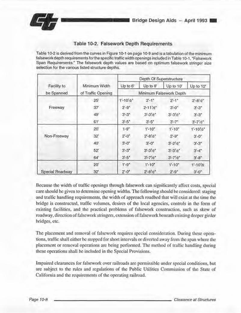
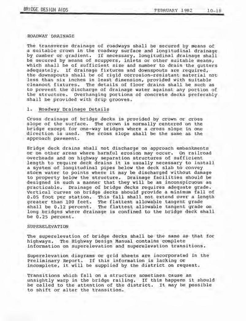
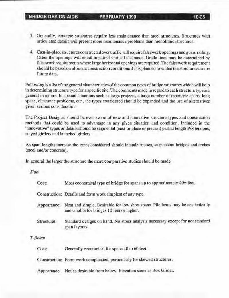
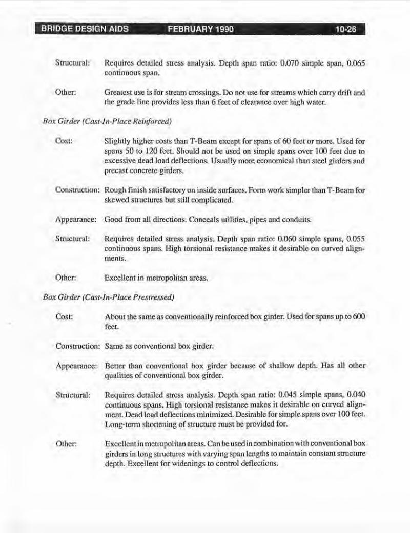
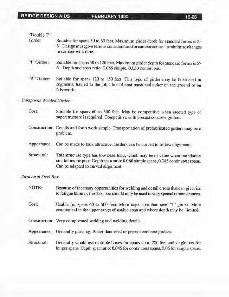
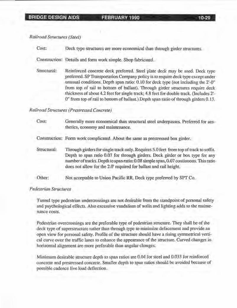
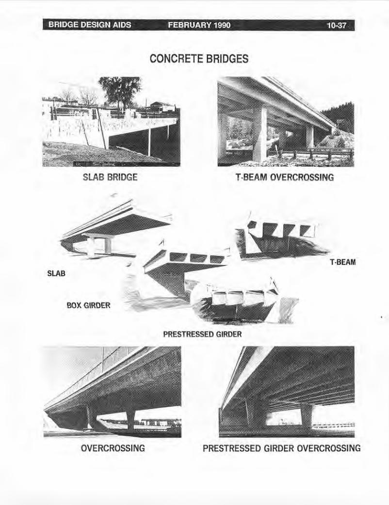
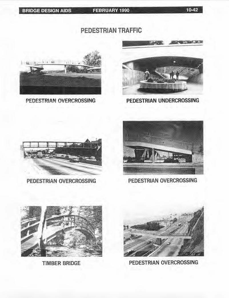
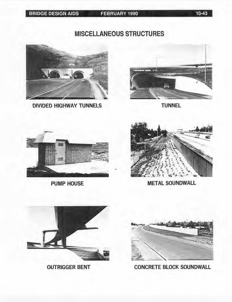
BRIDGE DESIGN AIDS FEBRUARY 1990 10-43
MISCELLANEOUS STRUCTURES
_
DIVIDED HIGHWAY TUNNELS TUNNEL
PUMP HOUSE METAL SOUNDWALL
-middot-
OUTRIGGER BENT CONCRETE BLOCK SOUNDWALL