Bridge, Hybrid, Notch Filter Shelf Rev 05 · PDF fileRaven 40100-4082 40200-208 41000-204...
45
Raven 40100-4082 40200-208 41000-204 2-Wire Bridge, 4-Wire Bridge, 2-Wire to 4-Wire Hybrid, and/or Notch Filter Shelf 40200 (2ru) Model Shown Users Manual Raven Electronics Corporation © 2009 Raven Electronics Corporation. All rights reserved. Rev. 05
Transcript of Bridge, Hybrid, Notch Filter Shelf Rev 05 · PDF fileRaven 40100-4082 40200-208 41000-204...

Raven 40100-4082 40200-208 41000-204
2-Wire Bridge, 4-Wire Bridge, 2-Wire to 4-Wire Hybrid, and/or Notch Filter Shelf
40200 (2ru) Model Shown
Users Manual
Raven Electronics Corporation
© 2009 Raven Electronics Corporation. All rights reserved. Rev. 05

Table of Contents
CHAPTER 1 INTRODUCTION .............................................................................................................. 1 General Information ..................................................................................................... 1 Safety Warning .............................................................................................................. 1 Raven Electronics’ Warranty ...................................................................................... 1 System Description ....................................................................................................... 2 CHAPTER 2 INSTALLING and SETTING UP THE BRIDGE SHELF ........................................................ 5 Equipment Needed for Installation ........................................................................... 5 Mounting Unit in Rack .................................................................................................. 5 Hooking Up Connections ............................................................................................ 6 CHAPTER 3 POWERING UP THE BRIDGE SHELF .............................................................................. 10 CHAPTER 4 TROUBLESHOOTING and ALIGNMENT ....................................................................... 11 Equipment Needed for Troubleshooting and Alignment .................................... 11 41620 Power Supply ................................................................................................... 11 41685 4-Way / 4-Wire Active Bridge ........................................................................ 12 41685-01 6-Way / 4-Wire Active Bridge ................................................................... 13 41688 8-Way / 4-Wire Active Bridge ........................................................................ 14 41667 Notch Filter ....................................................................................................... 16 41690 2-Wire to 4-Wire Hybrid ................................................................................... 17 41693 4-Way / 2-Wire Active Bridge, Summing/Splitting ...................................... 18 CHAPTER 5 SPECIFICATIONS .......................................................................................................... 19 CHAPTER 6 DIAGRAMS ................................................................................................................... 22 Front and Back Panel Diagrams .............................................................................. 22 40100-4082 ............................................................................................................ 22 40200-208 .............................................................................................................. 23 41000-204 .............................................................................................................. 24 40100-4082 Schematic ............................................................................................... 25 40200-208 Schematic ................................................................................................. 26 41000-204 Schematic ................................................................................................. 28 Block Diagrams 41620 Power Supply ............................................................................................. 31 41685 4-Way / 4-Wire Active Bridge .................................................................. 32 41685-01 6-Way / 4-Wire Active Bridge ............................................................ 32 41688 8-Way / 4-Wire Active Bridge .................................................................. 33 41667 Notch Filter ................................................................................................. 34 41690 2-Wire to 4-Wire Hybrid ............................................................................ 35 41693 4-Way / 2-Wire Active Bridge, Summing/Splitting ................................ 36 TABLE B INSTALLER CONNECTIONS .......................................................................................... 37 APPENDIX A OPTIONS ....................................................................................................................... 41 APPENDIX B GENERAL CONDITIONS OF SALES .............................................................................. 42
i

CHAPTER 1 INTRODUCTION General Information Thank you for purchasing a Bridge/Hybrid/Notch Filter Shelf from Raven Electronics Corporation. Please contact us if you have any questions, concerns, product ideas, or suggestions on how to improve this manual. We can be contacted at:
Raven Electronics Corporation 400 Edison Way
Reno, Nevada 89502 (775) 858-2400 Phone
(775) 858-2410 Fax [email protected] [email protected] www.ravencomm.com
! Please be Electro-Static Discharge (ESD) protected before
starting any procedures contained in this manual.
Raven Electronics’ Warranty
This warranty expressly precludes any liability by Raven for consequential damages however arising after delivery to the purchaser of the affected equipment, and is limited to the expressed warranty, excluding all implied warranties including merchantability. All equipment manufactured by Raven is warranted against defective materials and workmanship for a period of two (2) years from the date of delivery to the original purchaser or end-user. Liability under this warranty is limited to servicing, adjusting, repairing or replacing, as necessary, any equipment returned to the factory, transportation prepaid for that purpose. Factory examination must disclose a manufacturing defect. Repaired or replaced items will be returned to the purchaser surface freight prepaid within the continental U.S.A. This warranty does not extend to any equipment which has been subjected to transportation damage, misuse, neglect, accident, improper installation, or any other circumstances reasonably beyond the control of Raven. Beyond the warranty period, repairs will be billed to the purchaser at cost. In such cases, an estimate will be submitted for approval before repair is initiated. Repaired equipment will be returned to the purchaser with transportation charges collect, unless agreed to between the purchaser and Raven.
Safety Warning
1

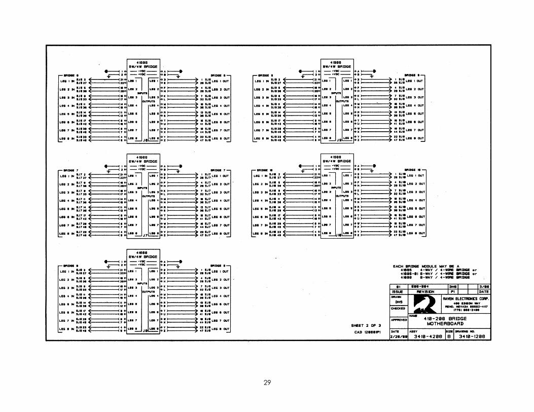
CHAPTER 1 INTRODUCTION System Description 40100-4082 The 40100-4082 Bridge/Hybrid/Notch Filter Shelf provides two mounting positions for the Raven 4-Wire/4-Way, 6-Way, 8-Way Active Bridges, 2-Wire/4-Way Active Bridge or Summing/Splitting, 2-Wire to 4-Wire Hybrids, and/or Notch Filters. The 4-Way and 6-Way Bridges are pin compatible with the 8-Way Bridge so that the shelf is wired for the 8-Way capacity, yet is still compatible with the smaller Bridges. The two mounting positions are stand-alone except for power, which maintains isolation between the audio circuits routed through the two Bridges. Alternatively, two 8-Way Bridges could be “daisy chained” to one another to form a single bridge function of greater capacity (up to a fourteen-way conference bridge). This is done by wiring the external Leg Out/Leg In port of one bridge to the Leg In/Leg Out port of the other bridge. In a similar manner, the 4-wire side of the 2-Wire/4-Wire Hybrids or Notch Filters can be connected to a 4-wire port of a bridge externally. The 40100D-4082 operates from a –24 to –56 VDC source, while the 40100A-4082 operates from a 110 or 220 VAC source. The modules that can be installed in the shelf are the 41685 4-Wire/4-Way Active Bridge, the 41685-01 4-Wire/6-Way Active Bridge, the 41688 4-Wire/8-Way Active Bridge, the 41693 2-Wire/Active Bridge or Summing/Splitting, the 41690 2-Wire to 4-Wire Hybrid, or the 41667 Notch Filters. Any combination of these modules can be installed in the 40100-4082 Bridge/Hybrid/Notch Filter Shelf. Maximum capacity is two modules per chassis. Amplifiers with potentiometer level adjustment are provided on each input and output for isolation, as well as, excellent common-mode rejection. All of these modules are removable for easy maintenance or replacement. 40100-4082-40X and -44X Options -40X and -44X are the same as the 40100-4082 with set options. The -40X has one 41685 Active Bridge Module installed. It also includes a 42067 Extender Board. The -44X has two 41685 Active Bridge Modules installed. It too includes a 42067 Extender Board. 40200-208 The model 40200-208 Bridge/Hybrid Shelf has eight mounting positions for the Raven 4-Wire/4-Way, 6-Way, 8-Way Active Bridges, 2-Wire/4-Way Active Bridge or Summing/Splitting, 2-Wire to 4-Wire Hybrids, and Notch Filters. The 4-Way and 6-Way Bridges are pin compatible with the 8-Way Bridge so that the shelf is wired for the 8-Way capacity, yet is still compatible with the smaller Bridges. The eight mounting positions are stand-alone except for power, which maintains isolation between the audio circuits routed through the eight Bridges. Alternatively, eight 8-Way Bridges could be “daisy chained” to one another to form a single bridge function of greater capacity (up to a 50-way conference bridge). This is done by wiring the external Leg Out/Leg In port of one bridge to the Leg In/Leg Out port of the next bridge and so on until all eight bridges (or however many are installed in the shelf). In a similar manner, the 4-wire side of the 2-Wire/4-Wire hybrids can be connected to a 4-wire port of a bridge externally. The 40100D-208 operates from a –24 to –56 VDC source, while the 40200A-208 operates from a 100 to 250 VAC source. Any combination of the above mentioned modules can be installed in the 40200-208 shelf. Maximum capacity is eight modules per chassis. All of these are active modules with +/- 25 dB of through path adjustment available. Amplifiers with potentiometer level adjustment are provided on each input and output for isolation, as well as, excellent common-mode rejection. All of these modules are removable for easy maintenance or replacement.
2

CHAPTER 1 INTRODUCTION 41000-204 The 41000-204 Bridge/Hybrid/Notch Filter Shelf provides interface between the Raven 4-wire/4-Way, 6-Way, 8-Way Active Bridges, 2-Wire/4-Way Active Bridge or Summing/Splitting, 2-Wire to 4-Wire Hybrid modules, 2-Wire/4-Way Bridge modules, or 4-Wire Notch Filter modules for fifteen individual circuits. Each module is wired to rear panel connectors, with only the power source being shared by the individual modules. Thus isolation is maintained between the circuits. Bridges may be connected together externally to form longer bridges where necessary. All inputs and outputs are transformer coupled for maximum isolation and common mode rejection. Amplifiers with potentiometer level adjustment are provided on each input and output for easy level coordination between ports. For 4-Way or 6-Way Bridges, 2-Wire/4-Way Bridges, Hybrid modules, 2-Wire/4-Wire Bridge modules, and Notch filters there are unused pins on the rear panel connectors. The modules that can be installed in the shelf are the 41685 4-Wire/4-Way Active Bridge, the 41685-01 4-Wire/6-Way Active Bridge, the 41688 4-Wire/8-Way Active Bridge, the 41693 2-Wire/Active Bridge or Summing/Splitting, the 41690 2-Wire to 4-Wire Hybrid, or the 41667 Notch Filters. Any combination of these modules can be installed in the 41000-204 Bridge/Hybrid/Notch Filter Shelf. Maximum capacity is fifteen modules per chassis. Amplifiers with potentiometer level adjustment are provided on each input and output for isolation, as well as, excellent common-mode rejection. All of these modules are removable for easy maintenance or replacement. 41620 Power Supply The Raven 41620 Regulated Power Supply provides a regulated -20 VDC output to power the Module(s). The 41620-01 regulates an input voltage ranging from -24 to -56 VDC. The 41620 provides foldback current limiting at an output current of approximately 1.2 amperes. Included on the 41620 is an ON/OFF power switch and a fuse in series with the input. 41667 Notch Filter The Raven 41667 Quad Notch Filter module can remove a single frequency within the normal pass baud. For frequencies outside the notch frequency, the level is adjustable over a 23dB range. The notch frequency is customer specified. The notch will be at least 50 dB down. The module is provided with one, two, three, or four filter circuits. 41685 4-Wire/4-Way Bridge The Raven 41685 4-Way/4-Wire Active Bridge provides a multipath interface between four ports on a 4-wire basis. An input at one of the ports is routed through to the output of all other ports, with a minimum of interchannel crosstalk. All inputs and outputs are transformer coupled and are balanced. Potentiometer adjustments on all inputs and outputs allow input level coordination and through-path gain adjustments. 41685-01 4-Wire/6-Way Bridge The Raven 41685-01 6-Way/4-Wire Active Bridge provides a multipath interface between six ports on a 4-wire basis. An input at one of the ports is routed through to the output of all other ports, with a minimum of interchannel crosstalk. All inputs and outputs are transformer coupled and are balanced. Potentiometer adjustments on all inputs and outputs allow input level coordination and through-path gain adjustments.
3

CHAPTER 1 INTRODUCTION 41688 4-Wire/8-Way Bridge The Raven 41688 8-Way/4-Wire Active Bridge provides a multipath interface between eight ports on a 4-wire basis. An input at one of the ports is routed through to the output of all other ports, with a minimum of interchannel crosstalk. All inputs and outputs are transformer coupled and are balanced. Potentiometer adjustments on all inputs and outputs allow input level coordination and through-path gain adjustments. 41690 2-Wire to 4-Wire Hybrid The Raven 41690 Quad 2-Wire to 4-Wire Hybrid module provides bi-directional access between a 2-wire line and a 4-wire network. The levels of the transmit and receive paths are each adjustable over a 23 dB range. The 41690 module is always ON, passing signals between the 2-wire line and the 4-wire circuits. The module is provided with one, two, three, or four 2-wire to 4-wire hybrid circuits. 41693 2-Wire/4-Way Active Bridge or Summing/Splitting The Raven 41693 2-Wire Bridge or Summing/Splitting module provides full 2-way conference bridging or bi-directional 1:3 splitting and 3:1 summing for 2-wire ports. The levels on the 2-wire ports are each adjustable over a 23 dB range. The 41693 module is always ON, passing signals between the 2-wire lines.
4
CHAPTER 2 INSTALLING and SETTING UP THE SHELF Equipment Needed for Installation Rackmount Equipment (to install unit in a rack):
• Screwdrivers (Flat blade and Phillips may be necessary) • Screws • Washers (optional)
Audio Connections:
• 24-Gauge Twisted Pair Wire Power Connections:
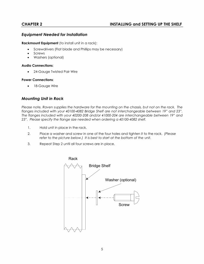
• 18-Gauge Wire Mounting Unit in Rack Please note, Raven supplies the hardware for the mounting on the chassis, but not on the rack. The flanges included with your 40100-4082 Bridge Shelf are not interchangeable between 19” and 23”. The flanges included with your 40200-208 and/or 41000-204 are interchangeable between 19” and 23”. Please specify the flange size needed when ordering a 40100-4082 shelf.
1. Hold unit in place in the rack.
2. Place a washer and screw in one of the four holes and tighten it to the rack. (Please refer to the picture below.) It is best to start at the bottom of the unit.
3. Repeat Step 2 until all four screws are in place.
5
Rack
Bridge Shelf
Washer (optional)
Screw

CHAPTER 2 INSTALLING and SETTING UP THE SHELF Hooking Up Connections With the source power turned off, use the following instructions to hook up your Bridge/Hybrid/Notch Filter Shelf. A small (1/8” blade) flat blade screwdriver is needed to loosen and tighten the terminal screws. It is not necessary to use lugs on the wires. Strip the wire(s) about 3/8”, loosen the terminal screw, insert the wire, then tighten the screw. You may refer to the charts below (also found in Table B). Be sure Power is turned OFF.
Please see pages 22-24 for rear panel diagrams.
FUNCTION50-PIN TELCO or
R250-0020 or R250-0021
R250-0023 WIRES40100-4082 TERMINALS MODULE 1
S66 PUNCH BLOCK PIN NUMBERS
Filter 1 Inputs 2, 27 WHT/ORG & ORG/WHT B1, B2 3, 4Filter 1 Outputs 1, 26 WHT/BLU & BLU/WHT C1, C2 1, 2Filter 2 Inputs 5, 30 WHT/GRY & GRY/WHT B3, B4 9, 10Filter 2 Outputs 4, 29 WHT/BRN & BRN/WHT C3, C4 7, 8Filter 3 Inputs 8, 33 RED/GRN & GRN/RED B5, B6 15, 16Filter 3 Outputs 7, 32 RED/ORG & ORG/RED C5, C6 13, 14Filter 4 Inputs 11, 36 BLK/BLU & BLU/BLK B7, B8 21, 22Filter 4 Outputs 10, 35 RED/GRY & GRY/RED C7, C8 19, 20
FUNCTIONREAR TERMINAL CONNECTIONS
REAR TERMINAL CONNECTIONS
REAR TERMINAL CONNECTIONS
SUGGESTED WIRE
GND A1 or SJ1 Center A1 or SJ9 Center A1 or SJ16 Center-VDC In A2 or SJ1 Sleeve A2 or SJ9 Sleeve A2 or SJ16 Sleeve
50-PIN TELCO, R250-0020, and R250-0021 are connections on 40200-208 or 41000-204 shelves.
R250-0023 are connections at the wire-end of a cable plugged into 40200-208 or 41000-204 shelves.
40100-4082 connections are to screw terminals on the rear panel.
S66 Punch Blocks are pre-wired for use with R250-0021 Male-Male cables. Pins are counted fromthe top when the block is mounted with the UP sign pointing at the top.
For connections to Filter Module 2 on the 40100-4082, use terminal blocks D and E with thesame terminal numbers.
POWER
Quad Notch Filter Connections
18 GA
6

CHAPTER 2 INSTALLING and SETTING UP THE SHELF
Please see pages 22-24 for rear panel diagrams.
FUNCTION50-PIN TELCO or
R250-0020 or R250-0021
R250-0023 WIRES40100-4082 TERMINALS MODULE 1
S66 PUNCH BLOCK PIN NUMBERS
Port 1 Inputs 2, 27 WHT/ORG & ORG/WHT B1, B2 3, 4Port 1 Outputs 1, 26 WHT/BLU & BLU/WHT C1, C2 1, 2Port 2 Inputs 5, 30 WHT/GRY & GRY/WHT B3, B4 9, 10Port 2 Outputs 4, 29 WHT/BRN & BRN/WHT C3, C4 7, 8Port 3 Inputs 8, 33 RED/GRN & GRN/RED B5, B6 15, 16Port 3 Outputs 7, 32 RED/ORG & ORG/RED C5, C6 13, 14Port 4 Inputs 11, 36 BLK/BLU & BLU/BLK B7, B8 21, 22Port 4 Outputs 10, 35 RED/GRY & GRY/RED C7, C8 19, 20Port 5 Inputs 14, 39 BLK/BRN & BRN/BLK B9, B10 27, 28Port 5 Outputs 13, 38 BLK/GRN & GRN/BLK C9, C10 25, 26Port 6 Inputs 17, 42 YEL/ORG & ORG/YEL B11, B12 33, 34Port 6 Outputs 16, 41 YEL/BLU & BLU/YEL C11, C12 31, 32Port 7 Inputs 20, 45 YEL/GRY & GRY/YEL B13, B14 39, 40Port 7 Outputs 19, 44 YEL/BRN & BRN/YEL C13, C14 37, 38Port 8 Inputs 23, 48 VIO/GRN & GRN/VIO B15, B16 45, 46Port 8 Outputs 22, 47 VIO/ORG & ORG/VIO C15, C16 43, 44
FUNCTIONREAR TERMINAL CONNECTIONS
REAR TERMINAL CONNECTIONS
REAR TERMINAL CONNECTIONS
SUGGESTED WIRE
GND A1 or SJ1 Center A1 or SJ9 Center A1 or SJ16 Center-VDC In A2 or SJ1 Sleeve A2 or SJ9 Sleeve A2 or SJ16 Sleeve
50-PIN TELCO, R250-0020, and R250-0021 are connections on 40200-208 or 41000-204 shelves.
R250-0023 are connections at the wire-end of a cable plugged into 40200-208 or 41000-204 shelves.
40100-4082 connections are to screw terminals on the rear panel.
S66 Punch Blocks are pre-wired for use with R250-0021 Male-Male cables. Pins are counted fromthe top when the block is mounted with the UP sign pointing at the top.
For connections to Bridge Module 2 on the 40100-4082, use terminal blocks D and E with thesame terminal numbers.
4-, 6-, or 8-Way Bridge Connections
POWER
18 GA
7

CHAPTER 2 INSTALLING and SETTING UP THE SHELF
Please see pages 22-24 for rear panel diagrams.
FUNCTION50-PIN TELCO or
R250-0020 or R250-0021
R250-0023 WIRES40100-4082 TERMINALS MODULE 1
S66 PUNCH BLOCK PIN NUMBERS
Hybrid 1 Inputs 2, 27 WHT/ORG & ORG/WHT B1, B2 3, 4Hybrid 1 Outputs 1, 26 WHT/BLU & BLU/WHT C1, C2 1, 22-Wire Line 1 22, 47 VIO/ORG & ORG/VIO C15, C16 43, 44Hybrid 1 LBO 14, 39 BLK/BRN & BRN/BLK B9, B10 27, 28Hybrid 2 Inputs 5, 30 WHT/GRY & GRY/WHT B3, B4 9, 10Hybrid 2 Outputs 4, 29 WHT/BRN & BRN/WHT C3, C4 7, 82-Wire Line 2 19, 44 YEL/BRN & BRN/YEL C13, C14 37, 38Hybrid 2 LBO 17, 42 YEL/ORG & ORG/YEL B11, B12 33, 34Hybrid 3 Inputs 8, 33 RED/GRN & GRN/RED B5, B6 15, 16Hybrid 3 Outputs 7, 32 RED/ORG & ORG/RED C5, C6 13, 142-Wire Line 3 16, 41 YEL/BLU & BLU/YEL C11, C12 31, 32Hybrid 3 LBO 20, 45 YEL/GRY & GRY/YEL B13, B14 39, 40Hybrid 4 Inputs 11, 36 BLK/BLU & BLU/BLK B7, B8 21, 22Hybrid 4 Outputs 10, 35 RED/GRY & GRY/RED C7, C8 19, 202-Wire Line 4 13, 38 BLK/GRN & GRN/BLK C9, C10 25, 26Hybrid 4 LBO 23, 48 VIO/GRN & GRN/VIO B15, B16 45, 46
FUNCTIONREAR TERMINAL CONNECTIONS
REAR TERMINAL CONNECTIONS
REAR TERMINAL CONNECTIONS
SUGGESTED WIRE
GND A1 or SJ1 Center A1 or SJ9 Center A1 or SJ16 Center-VDC In A2 or SJ1 Sleeve A2 or SJ9 Sleeve A2 or SJ16 Sleeve
50-PIN TELCO, R250-0020, and R250-0021 are connections on 40200-208 or 41000-204 shelves.
R250-0023 are connections at the wire-end of a cable plugged into 40200-208 or 41000-204 shelves.
40100-4082 connections are to screw terminals on the rear panel.
S66 Punch Blocks are pre-wired for use with R250-0021 Male-Male cables. Pins are counted fromthe top when the block is mounted with the UP sign pointing at the top.
For connections to Hybrid Module 2 on the 40100-4082, use terminal blocks D and E with thesame terminal numbers.
Quad 2-Wire to 4-Wire Hybrid Connections
POWER
18 GA
8

CHAPTER 2 INSTALLING and SETTING UP THE SHELF
Please see pages 22-24 for rear panel diagrams.
FUNCTION50-PIN TELCO or
R250-0020 or R250-0021
R250-0023 WIRES40100-4082 TERMINALS MODULE 1
S66 PUNCH BLOCK PIN NUMBERS
2-Wire Line 1 22, 47 VIO/ORG & ORG/VIO C15, C16 43, 44Bridge or SummingHybrid 1 LBO 14, 39 BLK/BRN & BRN/BLK B9, B10 27, 282-Wire Line 2 19, 44 YEL/BRN & BRN/YEL C13, C14 37, 38Bridge or SplittingHybrid 2 LBO 17, 42 YEL/ORG & ORG/YEL B11, B12 33, 342-Wire Line 3 16, 41 YEL/BLU & BLU/YEL C11, C12 31, 32Bridge or SplittingHybrid 3 LBO 20, 45 YEL/GRY & GRY/YEL B13, B14 39, 402-Wire Line 4 13, 38 BLK/GRN & GRN/BLK C9, C10 25, 26Bridge or SplittingHybrid 4 LBO 23, 48 VIO/GRN & GRN/VIO B15, B16 45, 46
FUNCTIONREAR TERMINAL CONNECTIONS FOR 40100-4082
REAR TERMINAL CONNECTIONS FOR 40200-208
REAR TERMINAL CONNECTIONS FOR 41000-204
SUGGESTED WIRE
GND A1 or SJ1 Center A1 or SJ9 Center A1 or SJ16 Center-VDC In A2 or SJ1 Sleeve A2 or SJ9 Sleeve A2 or SJ16 Sleeve
50-PIN TELCO, R250-0020, and R250-0021 are connections on 40200-208 or 41000-204 shelves.
R250-0023 are connections at the wire-end of a cable plugged into 40200-208 or 41000-204 shelves.
40100-4082 connections are to screw terminals on the rear panel.
S66 Punch Blocks are pre-wired for use with R250-0021 Male-Male cables. Pins are counted fromthe top when the block is mounted with the UP sign pointing at the top.
For connections to 2-Wire Bridge Module 2 on the 40100-4082, use terminal blocks D and E withthe same terminal numbers.
4-Way / 2-Wire Bridge or Summing/Splitting
POWER
18 GA
9

CHAPTER 3 POWERING UP THE SHELF Powering Up the Shelf Reinstall the module(s), if previously removed, before performing the following steps. Also, make sure the source power supply is turned off. Steps 1-6 apply to the DC powered model only. If using AC power, skip to step 7.
1. Open the front panel.
2. Verify the toggle switch is in the “off” position (to the right).
3. Turn on the external power source.
4. Flip the toggle switch to the “on” position (to the left).
5. The green light on the 41620 card (Power Supply) should be illuminated. If not, please refer to Chapter 4, Troubleshooting and Alignment.
6. Close the front panel.
7. If using AC powered version, plug the DC jack of the external power supply in to SJ1 (40100-4082), SJ9 (40200-208), or SJ16 (41000-204) on the rear panel. Refer to pages 22-24 for a rear panel view.
10

CHAPTER 4 TROUBLESHOOTING and ALIGNMENT Troubleshooting and Alignment Procedures Equipment Needed for Troubleshooting and Alignment:
• 42067 Extender Card (optional, but easier to align with)
• AC Voltmeter
• Alignment Tool
• Signal Generator Every shelf has been carefully aligned and tested at the factory. Please try the unit first before attempting the alignment procedures. No adjustment should be necessary since levels are set at the factory per customer’s specifications at time of order. If the unit is not working, it may need to be aligned. Attachment A lists all levels and impedances for the system. The Attachment A can be located inside the chassis. Caution must be exercised during level alignment to insure that proper test levels and impedances are maintained. A signal generator may double terminate a port causing a reduced signal level. When injecting a test tone into a port, bridge the port with an AC voltmeter and set the signal generator output according to the AC voltmeter reading. When taking output level readings, the AC voltmeter will be either terminated or bridged. If it is unknown whether an output reading should be a terminated or bridged measurement, compare the two readings. If a 3.5 dBm difference is noted, the bridged measurement is correct. If a 6.0 dBm difference is noted, the terminated measurement is correct. 41620 Power Supply Alignment Procedure
1. Turn power ON and verify LED CR7 illuminates.
2. Connect a DC voltmeter to test points TP1 and GND on the 41620 Power Supply and read –20.0 VDC.
3. Adjust R15 on the 41620 module, if required.
11

CHAPTER 4 TROUBLESHOOTING and ALIGNMENT Troubleshooting and Alignment Procedures (cont.) NOTE: This unit has already been aligned and tested in our factory per customer’s specifications
and it should function with little or no adjustments necessary. Please contact a Raven technician before making any adjustments suggested on this page.
41685 4-Way/4-Wire Bridge Level 1. Turn power off. Remove the 41685 4W/4W Bridge module and insert a 42067 Extender Card into
the module position. Insert the 41685 4W/4W Bridge into the Extender Card. Turn power on.
2. Connect the signal generator to pins 21 and 22 (LEG 1 IN) on the Extender Card. Set the signal generator frequency to 1 KHz at the level specified by Attachment A. Connect the AC voltmeter (terminate, if required) to pins F and H (LEG 2 OUT) on the Extender Card. Read the level specified by Attachment A. Adjust R2 on the 41685 4W/4W Active Bridge, if required.
3. Connect the AC voltmeter (terminate, if required) to pins K and L (LEG 3 OUT). Read the level specified by Attachment A. Adjust R3 on the 41685 4W/4W Active Bridge, if required.
4. Connect the AC voltmeter (terminate, if required) to pins M and N (LEG 4 OUT). Read the level specified by Attachment A. Adjust R4 on the 41685 4W/4W Active Bridge, if required.
5. Connect the signal generator to pins 19 and 20 (LEG 2 IN). Set the signal generator frequency to 1KHz at the level specified by Attachment A for LEG 2 IN.
6. With the AC voltmeter still connected to pins M and N, read the same level as in step 4. Adjust R8 on the 41685 4W/4W Active Bridge, if required.
7. Connect the AC voltmeter (bridging) to pins D and E (LEG 1 OUT). Read the level specified by Attachment A. Adjust R1 on the 41685 4W/4W Active Bridge, if required.
8. Connect the signal generator to pins 16 and 17 (LEG 3 IN). Set the signal generator level as specified by Attachment A. Read the same level on the AC voltmeter as in step 7. Adjust R9 on the 41685 4W/4W Active Bridge, if required.
9. Connect the signal generator to pins 14 and 15 (LEG 4 IN). Set the signal generator level as specified by Attachment A. Read the same level on the AC voltmeter as in step 7. Adjust R10 on the 41685 4W/4W Active Bridge, if required.
10. Disconnect all test equipment and turn power off. Remove the Extender Card and install the 41685 4W/4W Active Bridge in its position.
12

CHAPTER 4 TROUBLESHOOTING and ALIGNMENT Troubleshooting and Alignment Procedures (cont.) NOTE: This unit has already been aligned and tested in our factory per customer’s specifications
and it should function with little or no adjustments necessary. Please contact a Raven technician before making any adjustments suggested on this page.
41685-01 6-Way/4-Wire Bridge Level 1. Turn power off. Remove the 41685-01 6W/4W Bridge module and insert a 42067 Extender Card
into the module position. Insert the 41685-01 6W/4W Bridge into the Extender Card. Turn power on.
2. Connect the signal generator to pins 21 and 22 (LEG 1 IN) on the Extender Card. Set the signal generator frequency to 1 KHz at the level specified by Attachment A. Connect the AC voltmeter (terminate, if required) to pins F and H (LEG 2 OUT) on the Extender Card. Read the level specified by Attachment A. Adjust R2 on the 41685-01 6W/4W Active Bridge, if required.
3. Connect the AC voltmeter (terminate, if required) to pins K and L (LEG 3 OUT). Read the level specified by Attachment A. Adjust R3 on the 41685-01 6W/4W Active Bridge, if required.
4. Connect the AC voltmeter (terminate, if required) to pins M and N (LEG 4 OUT). Read the level specified by Attachment A. Adjust R4 on the 41685-01 6W/4W Active Bridge, if required.
5. Connect the AC voltmeter (terminate, if required) to pins R and S (LEG 5 OUT). Read the level specified by Attachment A. Adjust R5 on the 41685-01 6W/4W Active Bridge, if required.
6. Connect the AC voltmeter (terminate, if required) to pins T and U (LEG 6 OUT). Read the level specified by Attachment A. Adjust R6 on the 41685-01 6W/4W Active Bridge, if required.
7. Connect the signal generator to pins 19 and 20 (LEG 2 IN). Set the signal generator frequency to 1KHz at the level specified by Attachment A for LEG 2 IN.
8. With the AC voltmeter still connected to pins M and N, read the same level as in step 4. Adjust R8 on the 41685-01 6W/4W Active Bridge, if required.
9. Connect the AC voltmeter (bridging) to pins D and E (LEG 1 OUT). Read the level specified by Attachment A. Adjust R1 on the 41685-01 6W/4W Active Bridge, if required.
10. Connect the signal generator to pins 16 and 17 (LEG 3 IN). Set the signal generator level as specified by Attachment A. Read the same level on the AC voltmeter as in step 7. Adjust R9 on the 41685-01 6W/4W Active Bridge, if required.
11. Connect the signal generator to pins 14 and 15 (LEG 4 IN). Set the signal generator level as specified by Attachment A. Read the same level on the AC voltmeter as in step 7. Adjust R10 on the 41685-01 6W/4W Active Bridge, if required.
12. Connect the signal generator to pins 11 and 12 (LEG 5 IN). Set the signal generator level as specified by Attachment A. Read the same level on the AC voltmeter as in step 11. Adjust R13 on the 41685-01 6W/4W Active Bridge, if required.
13. Connect the signal generator to pins 9 and 10 (LEG 6 IN). Set the signal generator level as specified by Attachment A. Read the same level on the AC voltmeter as in step 11. Adjust R14 on the 41685-01 6W/4W Active Bridge, if required.
14. Disconnect all test equipment and turn power off. Remove the Extender Card and install the 41685-01 6W/4W Active Bridge in its position.
13

CHAPTER 4 TROUBLESHOOTING and ALIGNMENT Troubleshooting and Alignment Procedures (cont.) NOTE: This unit has already been aligned and tested in our factory per customer’s specifications
and it should function with little or no adjustments necessary. Please contact a Raven technician before making any adjustments suggested on this page.
41688 8-Way/4-Wire Bridge Level 1. Turn power off. Remove the 41688 8W/4W Bridge module and insert a 42067 Extender Card into
the module position. Insert the 41688 8W/4W Bridge into the Extender Card. Turn power on.
2. Connect the signal generator to pins 21 and 22 (LEG 1 IN) on the Extender Card. Set the signal generator frequency to 1 KHz at the level specified by Attachment A. Connect the AC voltmeter (terminate, if required) to pins F and H (LEG 2 OUT) on the Extender Card. Read the level specified by Attachment A. Adjust R2 on the 41688 8W/4W Active Bridge, if required.
3. Connect the AC voltmeter (terminate, if required) to pins K and L (LEG 3 OUT). Read the level specified by Attachment A. Adjust R3 on the 41688 8W/4W Active Bridge, if required.
4. Connect the AC voltmeter (terminate, if required) to pins M and N (LEG 4 OUT). Read the level specified by Attachment A. Adjust R4 on the 41688 8W/4W Active Bridge, if required.
5. Connect the AC voltmeter (terminate, if required) to pins R and S (LEG 5 OUT). Read the level specified by Attachment A. Adjust R5 on the 41688 8W/4W Active Bridge, if required.
6. Connect the AC voltmeter (terminate, if required) to pins T and U (LEG 6 OUT). Read the level specified by Attachment A. Adjust R6 on the 41688 8W/4W Active Bridge, if required.
7. Connect the AC voltmeter (terminate, if required) to pins W and X (LEG 7 OUT). Read the level specified by Attachment A. Adjust R7 on the 41688 8W/4W Active Bridge, if required.
8. Connect the AC voltmeter (terminate, if required) to pins Y and Z (LEG 8 OUT). Read the level specified by Attachment A. Adjust R8 on the 41688 8W/4W Active Bridge, if required.
9. Connect the signal generator to pins 19 and 20 (LEG 2 IN). Set the signal generator frequency to 1KHz at the level specified by Attachment A for LEG 2 IN.
10. With the AC voltmeter still connected to pins Y and Z, read the same level as in step 8. Adjust R10 on the 41688 8W/4W Active Bridge, if required.
11. Connect the AC voltmeter (bridging) to pins D and E (LEG 1 OUT). Read the level specified by Attachment A. Adjust R1 on the 41688 8W/4W Active Bridge, if required.
12. Connect the signal generator to pins 16 and 17 (LEG 3 IN). Set the signal generator level as specified by Attachment A. Read the same level on the AC voltmeter as in step 11. Adjust R11 on the 41688 8W/4W Active Bridge, if required.
13. Connect the signal generator to pins 14 and 15 (LEG 4 IN). Set the signal generator level as specified by Attachment A. Read the same level on the AC voltmeter as in step 11. Adjust R12 on the 41688 8W/4W Active Bridge, if required.
14. Connect the signal generator to pins 11 and 12 (LEG 5 IN). Set the signal generator level as specified by Attachment A. Read the same level on the AC voltmeter as in step 11. Adjust R13 on the 41688 8W/4W Active Bridge, if required.
14

CHAPTER 4 TROUBLESHOOTING and ALIGNMENT Troubleshooting and Alignment Procedures (cont.) 15. Connect the signal generator to pins 9 and 10 (LEG 6 IN). Set the signal generator level as
specified by Attachment A. Read the same level on the AC voltmeter as in step 11. Adjust R14 on the 41688 8W/4W Active Bridge, if required.
16. Connect the signal generator to pins 6 and 7 (LEG 7 IN). Set the signal generator level as specified by Attachment A. Read the same level on the AC voltmeter as in step 11. Adjust R15 on the 41688 8W/4W Active Bridge, if required.
17. Connect the signal generator to pins 4 and 5 (LEG 8 IN). Set the signal generator level as specified by Attachment A. Read the same level on the AC voltmeter as in step 11. Adjust R16 on the 41688 8W/4W Active Bridge, if required.
18. Disconnect all test equipment and turn power off. Remove the Extender Card and install the 41685 8W/4W Active Bridge in its position.
15
CHAPTER 4 TROUBLESHOOTING and ALIGNMENT Troubleshooting and Alignment Procedures (cont.) NOTE: This unit has already been aligned and tested in our factory per customer’s specifications
and it should function with little or no adjustments necessary. Please contact a Raven technician before making any adjustments suggested on this page.
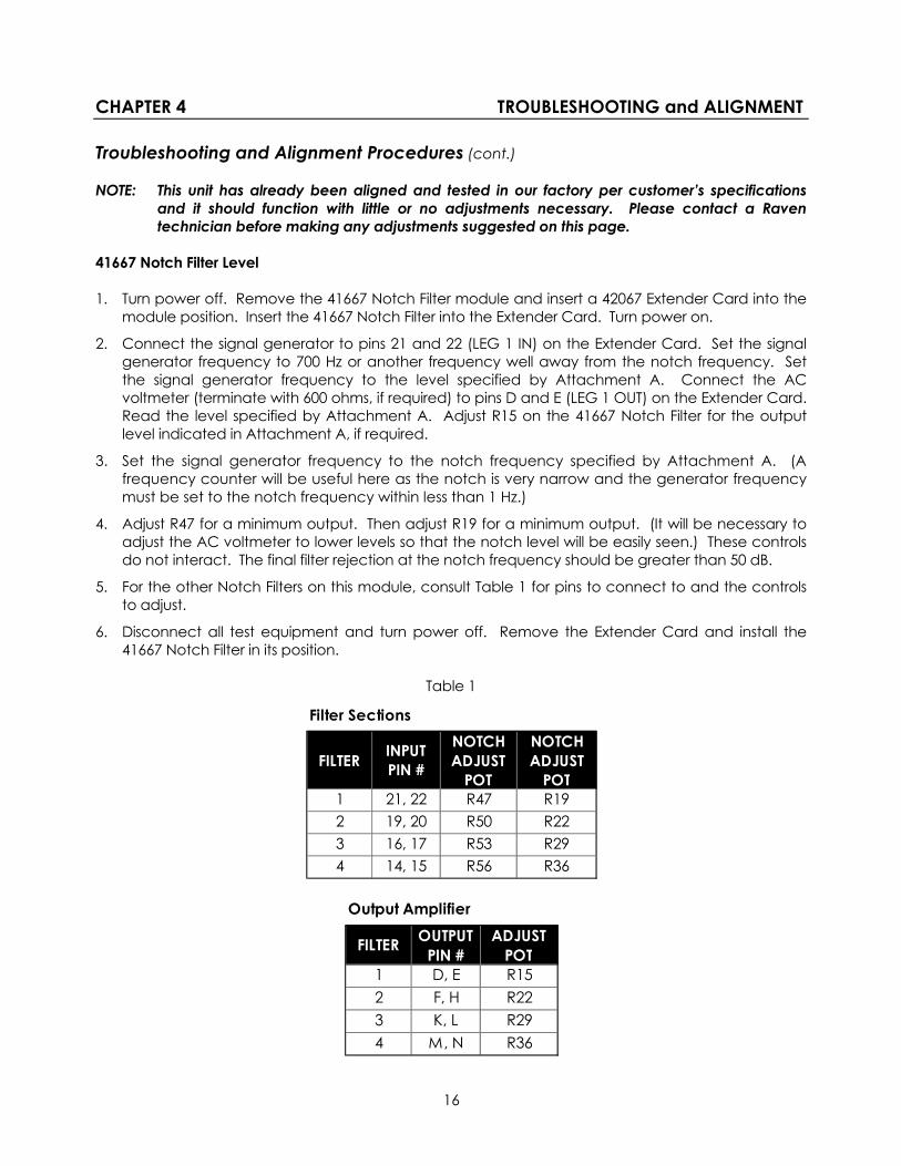
41667 Notch Filter Level 1. Turn power off. Remove the 41667 Notch Filter module and insert a 42067 Extender Card into the
module position. Insert the 41667 Notch Filter into the Extender Card. Turn power on.
2. Connect the signal generator to pins 21 and 22 (LEG 1 IN) on the Extender Card. Set the signal generator frequency to 700 Hz or another frequency well away from the notch frequency. Set the signal generator frequency to the level specified by Attachment A. Connect the AC voltmeter (terminate with 600 ohms, if required) to pins D and E (LEG 1 OUT) on the Extender Card. Read the level specified by Attachment A. Adjust R15 on the 41667 Notch Filter for the output level indicated in Attachment A, if required.
3. Set the signal generator frequency to the notch frequency specified by Attachment A. (A frequency counter will be useful here as the notch is very narrow and the generator frequency must be set to the notch frequency within less than 1 Hz.)
4. Adjust R47 for a minimum output. Then adjust R19 for a minimum output. (It will be necessary to adjust the AC voltmeter to lower levels so that the notch level will be easily seen.) These controls do not interact. The final filter rejection at the notch frequency should be greater than 50 dB.
5. For the other Notch Filters on this module, consult Table 1 for pins to connect to and the controls to adjust.
6. Disconnect all test equipment and turn power off. Remove the Extender Card and install the 41667 Notch Filter in its position.
Table 1
Filter Sections
FILTER INPUT PIN #
NOTCH ADJUST
POT
NOTCH ADJUST
POT1 21, 22 R47 R192 19, 20 R50 R223 16, 17 R53 R294 14, 15 R56 R36
Output Amplifier
FILTER OUTPUT PIN #
ADJUST POT
1 D, E R152 F, H R223 K, L R294 M, N R36
16

CHAPTER 4 TROUBLESHOOTING and ALIGNMENT Troubleshooting and Alignment Procedures (cont.) NOTE: This unit has already been aligned and tested in our factory per customer’s specifications
and it should function with little or no adjustments necessary. Please contact a Raven technician before making any adjustments suggested on this page.
41690 2-Wire to 4-Wire Hybrid Level 1. Turn power off. Remove the 41690 Hybrid module and insert a 42067 Extender Card into the
module position. Insert the 41690 Hybrid into the Extender Card. Turn power on.
2. Connect the signal generator to pins 21 and 22 (Hybrid 1) on the Extender Card. Set the signal generator frequency to 1 KHz at the level specified by Attachment A for input. Connect the AC voltmeter (terminate with 600 ohms, if required) to pins Y and Z.
3. Read the level specified by Attachment A for Hybrid 1 2-Wire line output. Adjust R7 for a level of 0 dBm. Remove the signal generator from pins 21 and 22.
4. Connect the signal generator to pins Y and Z. Set the signal generator frequency to 1 KHz at a level of 0 dBm. Connect the AC voltmeter (terminate with 600 ohms, if required) to pins D and E.
5. Read the level specified by Attachment A for Hybrid 1 4-Wire Output. Adjust R2, if required.
6. Connect the signal generator to pins 21 and 22 (Hybrid 1) on the Extender Card. Set the signal generator frequency to 1 KHz at the level specified by Attachment A for 4-Wire line Input. Make sure there is a single 600 ohm load on the 2-wire line. Adjust R11 for a minimum reading on the AC Voltmeter. The reading obtained should be greater than 25 dB down from the output level specified by Attachment A.
In some cases, hybrid balance will be improved by switching in capacitors in the balance circuit. Start by turning on Position 1 of SW1 and readjust R11 for a minimum reading. Additional capacitors may be switched on as needed. Always adjust the hybrid balance pot for minimum reading on the output meter.
7. For the other Hybrids on this module, consult Table 2 for pins to connect to and the controls to adjust.
8. Disconnect all test equipment and turn power off. Remove the Extender Card and install the 41690 Hybrid in its position.
Table 2
HYBRID RCV IN POT XMT OUT POT 2-WIRE LINE
HYBRID POT SWITCH
1 21, 22 R7 D, E R2 Y, Z R11 SW12 19, 20 R19 F, H R14 W, X R23 SW23 16, 17 R31 K, L R26 T, U R35 SW34 14, 15 R43 M, N R38 R, S R47 SW4
17

CHAPTER 4 TROUBLESHOOTING and ALIGNMENT
Troubleshooting and Alignment Procedures (cont.) NOTE: This unit has already been aligned and tested in our factory per customer’s specifications
and it should function with little or no adjustments necessary. Please contact a Raven technician before making any adjustments suggested on this page.
41693 2-Wire/4-Way Active Bridge, Summing/Splitting 1. Turn power off. Remove the 41693 Bridge/Summing/Splitting module and insert a 42067 Extender
Card into the module position. Insert the 41693 Bridge/Summing/Splitting into the Extender Card. On the 41693, set all positions of SW1-4 off. Turn power on. Make sure that each LEG of this bridge has 600 ohm load or source impedance connected to it. Keep in mind that when a 600 ohm signal generator is connected to the LEG that the external load or source must be disconnected.
2. Connect the signal generator to pins Y and Z on the Extender Card. Set the signal generator frequency to 1 KHz at the level of 0 dBm. Connect the AC voltmeter (unterminated) to U2 pin 7 and GND. Adjust R23 for a null.
3. Connect an AC voltmeter (unterminated) to U3 pin 7 and GND. Adjust R35 for a null.
4. Connect an AC voltmeter (unterminated) to U4 pin 7 and GND. Adjust R47 for a null.
5. Connect the signal generator to pins W and X on the Extender Card. Set the signal generator frequency to 1 KHz at a level of 0 dBm. Connect an AC voltmeter (unterminated) to U1 pin 7 and GND. Adjust R11 for a null.
6. Connect an AC voltmeter (unterminated) to U2 pin 7 and GND. Adjust R16 for 0 dBm on the meter.
7. Connect an AC voltmeter (unterminated) to U1 pin 1 and GND. Adjust R9 for +10 dBm output.
8. Connect an AC voltmeter (unterminated) to U3 pin 1 and GND. Adjust R33 for +10 dBm output.
9. Connect an AC voltmeter (unterminated) to U4 pin 1 and GND. Adjust R45 for +10 dBm output.
10. Connect a signal generator to pins Y and Z. Set the signal generator frequency to 1 KHz at a level of 0 dBm. Connect an AC voltmeter (unterminated) to U1 pin 7 and GND. Adjust R4 for 0 dBm.
11. Connect an AC voltmeter (unterminated) to U2 pin 1 and GND. Adjust R21 for +10 dBm output.
12. Connect a signal generator to pins T and U. Set the signal generator frequency to 1 KHz at a level of 0 dBm output. Connect an AC voltmeter (unterminated) to U3 pin 7 and GND. Adjust R28 for 0 dBm output.
13. Connect a signal generator to pins R and S. Set the signal generator frequency to 1 KHz at a level of 0 dBm output. Connect an AC voltmeter (unterminated) to U4 pin 7 and GND. Adjust R40 for 0 dBm output.
14. Disconnect all test equipment and turn power off. Remove the Extender Card and install the 41693 Bridge/Summing/Splitting module in its position.
18

CHAPTER 5 SPECIFICATIONS
Specifications 40100-4082 Bridge/Hybrid/Notch Filter Shelf
POWER REQUIREMENT -24 to -56 VDC input power or 110/220 VAC, 47-63 Hz
CURRENT DRAIN 110 mA (max) with DC power 10 watts max with AC power
4-WIRE INTERFACE * Line Impedance (XMT & RCV) 600, 75 ohms or customer specified * Levels (XMT & RCV) -46 to +7 dBm, adjustable Frequency Response +1, -3 dBm0 (300 Hz to 20 KHz, bridges only) † Crosstalk (RCV & XMT) Less than –50 dBm0 at unity gain
(300 Hz to 20 KHz, bridges only)
2-WIRE LEVEL 0 dBm (nominal) @ 600Ω Hybrid Trans-Hybrid Loss >30 dB Longitudinal Balance >60 dB
Notch Filter * Notch Frequency Customer Specified Notch Depth >50 dB
ENVIRONMENTAL Operating Temperature 0°C to +50°C Storage Temperature -50°C to +80°C Relative Humidity 0 to 95% non-condensing Operating Altitude 15,000 ft max (4572 meters)
DIMENSIONS Width (Standard) 19.00 inches rackmount (48.26 cm) (Optional) 23.00 inches rackmount (58.42 cm) Depth 14.75 inches (37.465 cm) Height 1.75 inches (4.445 cm) (1 ru)
WEIGHT (max) 12 pounds max. (5.44 kg)
* Customer Specified † 4-Wire and Data Interface set for 0 dBM 600 ohms IN and OUT @ 1 KHz
19

CHAPTER 5 SPECIFICATIONS Specifications 40200-208 Bridge/Hybrid/Notch Filter Shelf
POWER REQUIREMENT -24 to -56 VDC input power or 110/220 VAC, 47-63 Hz
CURRENT DRAIN 500 mA max for DC input 25 watts max for AC input
4-WIRE INTERFACE * Line Impedance (XMT & RCV) 600, 75 ohms or customer specified * Levels (XMT & RCV) -46 to +7 dBm, adjustable Frequency Response +1, -3 dBm0 (300 Hz to 20 KHz, bridges only) † Crosstalk (RCV & XMT) Less than –50 dBm0 at unity gain
(300 Hz to 20 KHz, bridges only)
2-WIRE LEVEL 0 dBm (nominal) @ 600Ω Hybrid Trans-Hybrid Loss >30 dB Longitudinal Balance >60 dB
Notch Filter * Notch Frequency Customer Specified Notch Depth >50 dB
ENVIRONMENTAL Operating Temperature 0°C to +50°C Storage Temperature -50°C to +80°C Relative Humidity 0 to 95% non-condensing Operating Altitude 15,000 ft max (4572 meters)
DIMENSIONS Width (Standard) 19.00 inches rackmount (48.26 cm) (Optional) 23.00 inches rackmount (58.42 cm) Depth 14.75 inches (37.465 cm) Height 3.5 inches (8.9 cm) (2 ru)
WEIGHT (max) 14 pounds max. (6.36 kg)
* Customer Specified † 4-Wire and Data Interface set for 0 dBM 600 ohms IN and OUT @ 1 KHz
20

CHAPTER 5 SPECIFICATIONS Specifications 41000-204 Bridge/Hybrid/Notch Filter Shelf
POWER REQUIREMENT -24 to -56 VDC input power or 110/220 VAC, 47-63 Hz
CURRENT DRAIN 1.00 Amp max for DC input 25 watts max for AC input
4-WIRE INTERFACE * Line Impedance (XMT & RCV) 600, 75 ohms or customer specified * Levels (XMT & RCV) -46 to +7 dBm, adjustable Frequency Response +1, -3 dBm0 (300 Hz to 20 KHz, bridges only) † Crosstalk (RCV & XMT) Less than –50 dBm0 at unity gain
(300 Hz to 20 KHz, bridges only)
2-WIRE LEVEL 0 dBm (nominal) @ 600Ω Hybrid Trans-Hybrid Loss >30 dB Longitudinal Balance >60 dB
Notch Filter * Notch Frequency Customer Specified Notch Depth >50 dB
ENVIRONMENTAL Operating Temperature 0°C to +50°C Storage Temperature -50°C to +80°C Relative Humidity 0 to 95% non-condensing Operating Altitude 15,000 ft max (4572 meters)
DIMENSIONS Width (Standard) 19.00 inches rackmount (48.26 cm) (Optional) 23.00 inches rackmount (58.42 cm) Depth 14.75 inches (37.465 cm) Height 5.25 inches (13.335 cm) (3 ru)
WEIGHT (max) 25 pounds max. (11.34 kg)
* Customer Specified † 4-Wire and Data Interface set for 0 dBM 600 ohms IN and OUT @ 1 KHz
21

CHAPTER 6 DIAGRAMS 40100-4082 Front Panel
40100-4082 Back Panel Diagram
22
40100-4082 Bridge/Hybrid/Notch Filter Shelf (Rear View)
Not drawn to scale.

CHAPTER 6 DIAGRAMS 40200-208 Front Panel
40200-208 Back Panel Diagram
50-Pin Connector Pin-Out Diagram Pin 25 Pin 1
Pin 50 Pin 26
REAR PANEL VIEW
40200-208
SJ9DC POWER
INPUT A
-24 TO -56 VDC
GND
SJ5MODULE 5
SJ6MODULE 6
SJ7MODULE 7
SJ8MODULE 8
SJ1MODULE 1
SJ2MODULE 2
SJ3MODULE 3
SJ4MODULE 4
40200-208 Bridge/Hybrid/Notch Filter Shelf (Rear View)
Not drawn to scale.
23
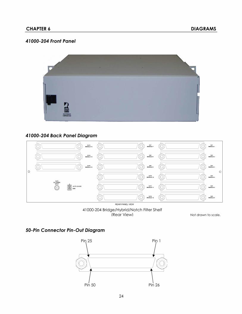
CHAPTER 6 DIAGRAMS 41000-204 Front Panel
41000-204 Back Panel Diagram
50-Pin Connector Pin-Out Diagram Pin 25 Pin 1
Pin 50 Pin 26
REAR PANEL VIEW
41000-204
SJ16DC POWER
INPUT A
-24 TO -56 VDC
GND
SJ9MODULE 9
SJ10MODULE 10
SJ11MODULE 11
SJ12MODULE 12
SJ3MODULE 3
SJ4MODULE 4
SJ5MODULE 5
SJ6MODULE 6
SJ7MODULE 7
SJ8MODULE 8
SJ1MODULE 1
SJ2MODULE 2
SJ15MODULE 15
SJ13MODULE 13
SJ14MODULE 14
41000-204 Bridge/Hybrid/Notch Filter Shelf (Rear View) Not drawn to scale.
24

25

26

27

28
29

30

31

32

33

34

35

36

TABLE B INSTALLER CONNECTIONS 41667 Notch Filter Installer Connections
FUNCTION50-PIN TELCO or
R250-0020 or R250-0021
R250-0023 WIRES40100-4082 TERMINALS MODULE 1
S66 PUNCH BLOCK PIN NUMBERS
Filter 1 Inputs 2, 27 WHT/ORG & ORG/WHT B1, B2 3, 4Filter 1 Outputs 1, 26 WHT/BLU & BLU/WHT C1, C2 1, 2Filter 2 Inputs 5, 30 WHT/GRY & GRY/WHT B3, B4 9, 10Filter 2 Outputs 4, 29 WHT/BRN & BRN/WHT C3, C4 7, 8Filter 3 Inputs 8, 33 RED/GRN & GRN/RED B5, B6 15, 16Filter 3 Outputs 7, 32 RED/ORG & ORG/RED C5, C6 13, 14Filter 4 Inputs 11, 36 BLK/BLU & BLU/BLK B7, B8 21, 22Filter 4 Outputs 10, 35 RED/GRY & GRY/RED C7, C8 19, 20
FUNCTIONREAR TERMINAL CONNECTIONS
REAR TERMINAL CONNECTIONS
REAR TERMINAL CONNECTIONS
SUGGESTED WIRE
GND A1 or SJ1 Center A1 or SJ9 Center A1 or SJ16 Center-VDC In A2 or SJ1 Sleeve A2 or SJ9 Sleeve A2 or SJ16 Sleeve
50-PIN TELCO, R250-0020, and R250-0021 are connections on 40200-208 or 41000-204 shelves.
R250-0023 are connections at the wire-end of a cable plugged into 40200-208 or 41000-204 shelves.
40100-4082 connections are to screw terminals on the rear panel.
S66 Punch Blocks are pre-wired for use with R250-0021 Male-Male cables. Pins are counted fromthe top when the block is mounted with the UP sign pointing at the top.
For connections to Filter Module 2 on the 40100-4082, use terminal blocks D and E with thesame terminal numbers.
POWER
Quad Notch Filter Connections
18 GA
37

TABLE B INSTALLER CONNECTIONS 41685, 41685-01, and 41688 Bridge Module Installer Connections
FUNCTION50-PIN TELCO or
R250-0020 or R250-0021
R250-0023 WIRES40100-4082 TERMINALS MODULE 1
S66 PUNCH BLOCK PIN NUMBERS
Port 1 Inputs 2, 27 WHT/ORG & ORG/WHT B1, B2 3, 4Port 1 Outputs 1, 26 WHT/BLU & BLU/WHT C1, C2 1, 2Port 2 Inputs 5, 30 WHT/GRY & GRY/WHT B3, B4 9, 10Port 2 Outputs 4, 29 WHT/BRN & BRN/WHT C3, C4 7, 8Port 3 Inputs 8, 33 RED/GRN & GRN/RED B5, B6 15, 16Port 3 Outputs 7, 32 RED/ORG & ORG/RED C5, C6 13, 14Port 4 Inputs 11, 36 BLK/BLU & BLU/BLK B7, B8 21, 22Port 4 Outputs 10, 35 RED/GRY & GRY/RED C7, C8 19, 20Port 5 Inputs 14, 39 BLK/BRN & BRN/BLK B9, B10 27, 28Port 5 Outputs 13, 38 BLK/GRN & GRN/BLK C9, C10 25, 26Port 6 Inputs 17, 42 YEL/ORG & ORG/YEL B11, B12 33, 34Port 6 Outputs 16, 41 YEL/BLU & BLU/YEL C11, C12 31, 32Port 7 Inputs 20, 45 YEL/GRY & GRY/YEL B13, B14 39, 40Port 7 Outputs 19, 44 YEL/BRN & BRN/YEL C13, C14 37, 38Port 8 Inputs 23, 48 VIO/GRN & GRN/VIO B15, B16 45, 46Port 8 Outputs 22, 47 VIO/ORG & ORG/VIO C15, C16 43, 44
FUNCTIONREAR TERMINAL CONNECTIONS
REAR TERMINAL CONNECTIONS
REAR TERMINAL CONNECTIONS
SUGGESTED WIRE
GND A1 or SJ1 Center A1 or SJ9 Center A1 or SJ16 Center-VDC In A2 or SJ1 Sleeve A2 or SJ9 Sleeve A2 or SJ16 Sleeve
50-PIN TELCO, R250-0020, and R250-0021 are connections on 40200-208 or 41000-204 shelves.
R250-0023 are connections at the wire-end of a cable plugged into 40200-208 or 41000-204 shelves.
40100-4082 connections are to screw terminals on the rear panel.
S66 Punch Blocks are pre-wired for use with R250-0021 Male-Male cables. Pins are counted fromthe top when the block is mounted with the UP sign pointing at the top.
For connections to Bridge Module 2 on the 40100-4082, use terminal blocks D and E with thesame terminal numbers.
4-, 6-, or 8-Way Bridge Connections
POWER
18 GA
38
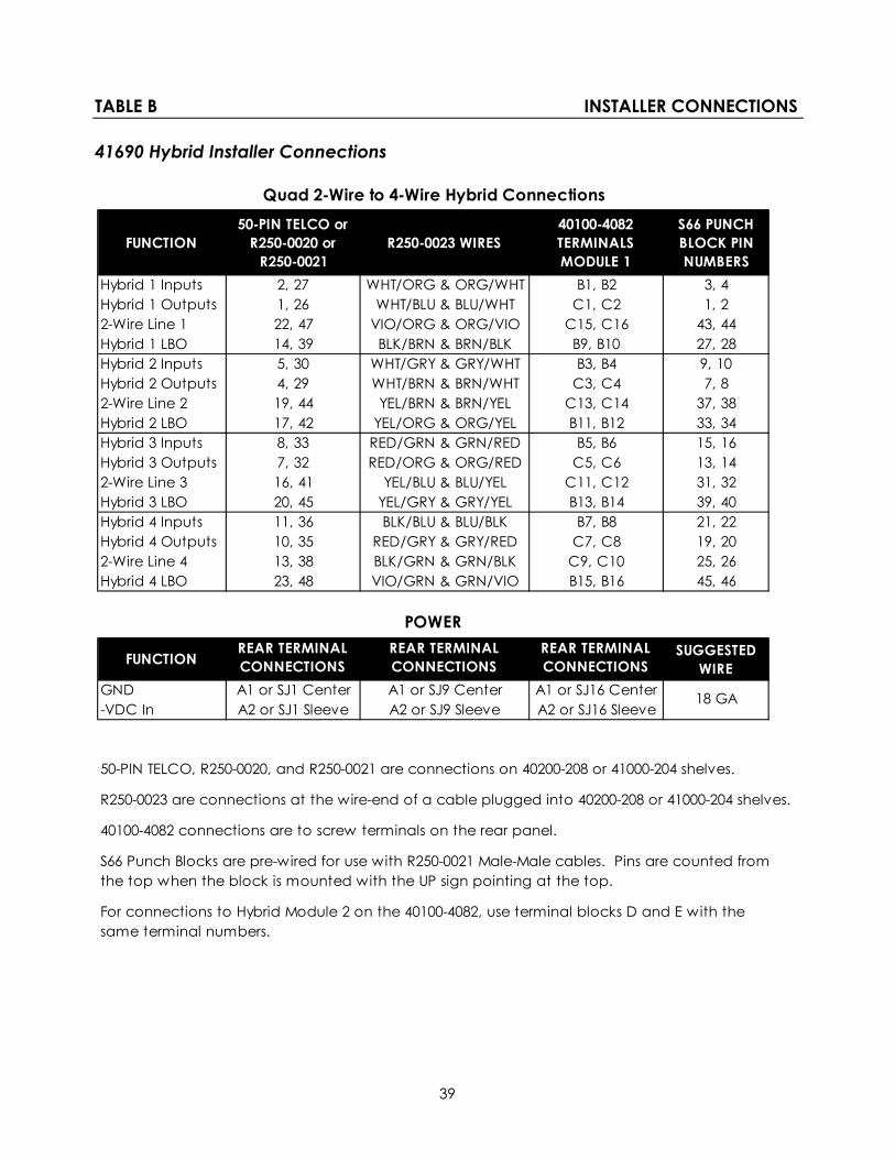
TABLE B INSTALLER CONNECTIONS 41690 Hybrid Installer Connections
FUNCTION50-PIN TELCO or
R250-0020 or R250-0021
R250-0023 WIRES40100-4082 TERMINALS MODULE 1
S66 PUNCH BLOCK PIN NUMBERS
Hybrid 1 Inputs 2, 27 WHT/ORG & ORG/WHT B1, B2 3, 4Hybrid 1 Outputs 1, 26 WHT/BLU & BLU/WHT C1, C2 1, 22-Wire Line 1 22, 47 VIO/ORG & ORG/VIO C15, C16 43, 44Hybrid 1 LBO 14, 39 BLK/BRN & BRN/BLK B9, B10 27, 28Hybrid 2 Inputs 5, 30 WHT/GRY & GRY/WHT B3, B4 9, 10Hybrid 2 Outputs 4, 29 WHT/BRN & BRN/WHT C3, C4 7, 82-Wire Line 2 19, 44 YEL/BRN & BRN/YEL C13, C14 37, 38Hybrid 2 LBO 17, 42 YEL/ORG & ORG/YEL B11, B12 33, 34Hybrid 3 Inputs 8, 33 RED/GRN & GRN/RED B5, B6 15, 16Hybrid 3 Outputs 7, 32 RED/ORG & ORG/RED C5, C6 13, 142-Wire Line 3 16, 41 YEL/BLU & BLU/YEL C11, C12 31, 32Hybrid 3 LBO 20, 45 YEL/GRY & GRY/YEL B13, B14 39, 40Hybrid 4 Inputs 11, 36 BLK/BLU & BLU/BLK B7, B8 21, 22Hybrid 4 Outputs 10, 35 RED/GRY & GRY/RED C7, C8 19, 202-Wire Line 4 13, 38 BLK/GRN & GRN/BLK C9, C10 25, 26Hybrid 4 LBO 23, 48 VIO/GRN & GRN/VIO B15, B16 45, 46
FUNCTIONREAR TERMINAL CONNECTIONS
REAR TERMINAL CONNECTIONS
REAR TERMINAL CONNECTIONS
SUGGESTED WIRE
GND A1 or SJ1 Center A1 or SJ9 Center A1 or SJ16 Center-VDC In A2 or SJ1 Sleeve A2 or SJ9 Sleeve A2 or SJ16 Sleeve
50-PIN TELCO, R250-0020, and R250-0021 are connections on 40200-208 or 41000-204 shelves.
R250-0023 are connections at the wire-end of a cable plugged into 40200-208 or 41000-204 shelves.
40100-4082 connections are to screw terminals on the rear panel.
S66 Punch Blocks are pre-wired for use with R250-0021 Male-Male cables. Pins are counted fromthe top when the block is mounted with the UP sign pointing at the top.
For connections to Hybrid Module 2 on the 40100-4082, use terminal blocks D and E with thesame terminal numbers.
Quad 2-Wire to 4-Wire Hybrid Connections
POWER
18 GA
39

TABLE B INSTALLER CONNECTIONS 41693 4-Way/2-Wire Active Bridge or Summing/Splitting Installer Connections
FUNCTION50-PIN TELCO or
R250-0020 or R250-0021
R250-0023 WIRES40100-4082 TERMINALS MODULE 1
S66 PUNCH BLOCK PIN NUMBERS
2-Wire Line 1 22, 47 VIO/ORG & ORG/VIO C15, C16 43, 44Bridge or SummingHybrid 1 LBO 14, 39 BLK/BRN & BRN/BLK B9, B10 27, 282-Wire Line 2 19, 44 YEL/BRN & BRN/YEL C13, C14 37, 38Bridge or SplittingHybrid 2 LBO 17, 42 YEL/ORG & ORG/YEL B11, B12 33, 342-Wire Line 3 16, 41 YEL/BLU & BLU/YEL C11, C12 31, 32Bridge or SplittingHybrid 3 LBO 20, 45 YEL/GRY & GRY/YEL B13, B14 39, 402-Wire Line 4 13, 38 BLK/GRN & GRN/BLK C9, C10 25, 26Bridge or SplittingHybrid 4 LBO 23, 48 VIO/GRN & GRN/VIO B15, B16 45, 46
FUNCTIONREAR TERMINAL CONNECTIONS FOR 40100-4082
REAR TERMINAL CONNECTIONS FOR 40200-208
REAR TERMINAL CONNECTIONS FOR 41000-204
SUGGESTED WIRE
GND A1 or SJ1 Center A1 or SJ9 Center A1 or SJ16 Center-VDC In A2 or SJ1 Sleeve A2 or SJ9 Sleeve A2 or SJ16 Sleeve
50-PIN TELCO, R250-0020, and R250-0021 are connections on 40200-208 or 41000-204 shelves.
R250-0023 are connections at the wire-end of a cable plugged into 40200-208 or 41000-204 shelves.
40100-4082 connections are to screw terminals on the rear panel.
S66 Punch Blocks are pre-wired for use with R250-0021 Male-Male cables. Pins are counted fromthe top when the block is mounted with the UP sign pointing at the top.
For connections to 2-Wire Bridge Module 2 on the 40100-4082, use terminal blocks D and E withthe same terminal numbers.
4-Way / 2-Wire Bridge or Summing/Splitting
POWER
18 GA
40

APPENDIX A OPTIONS Bridge shelf Options Model # Description
40100D-4082 Bridge/Hybrid/Notch Filter Shelf (DC Power) Includes 2-3 modules: 1-2 Active Bridge, Notch Filter, and/or Hybrid Modules, (41685 4-Way/4-Wire Active Bridge, and/or 41685-01 6-Way/4-Wire Active Bridge, and/or 41688 8-Way/4-Wire Active Bridge, and/or 41667 Notch Filter, and/or 41690 2-Wire to 4-Wire Hybrid, and/or 41693 4-Way /2-Wire Active Bridge) 41620-01 DC Power Supply (-24 to -56 VDC input power)
40100A-4082 Bridge/Hybrid/Notch Filter Shelf (AC Power) Same as above, however the 41620-01 power supply is not installed and the unit is powered from an external AC power supply (100 to 250 VAC input).
40200D-208 Bridge/Hybrid/Notch Filter Shelf (DC Power) Includes 2-9 modules: 1-8 Active Bridge, Notch Filter, and/or Hybrid Modules, (41685 4-Way/4-Wire Active Bridge, and/or 41685-01 6-Way/4-Wire Active Bridge, and/or 41688 8-Way/4-Wire Active Bridge and/or 41667 Notch Filter, and/or 41690 2-Wire to 4-Wire Hybrid, and/or 41693 4-Way /2-Wire Active Bridge) 41620-01 DC Power Supply (-24 to -56 VDC input power)
40200A-208 Bridge/Hybrid/Notch Filter Shelf (AC Power) Same as above, the unit is powered from an external AC power supply (100 to 250 VAC input).
41000D-204 Bridge/Hybrid/Notch Filter Shelf (DC Power) Includes 2-15 modules:
1-14 Active Bridge, Notch Filter, and/or Hybrid Modules, (41685 4-Way/4-Wire Active Bridge, and/or 41685-01 6-Way/4-Wire Active Bridge, and/or 41688 8-Way/4-Wire Active Bridge and/or 41667 Notch Filter, and/or 41690 2-Wire to 4-Wire Hybrid, and/or 41693 4-Way /2-Wire Active Bridge) 41620-01 DC Power Supply (-24 to -56 VDC input power)
41000A-204 Bridge/Hybrid/Notch Filter Shelf (AC Power) Same as above, the unit is powered from an external AC power supply (100 to 250 VAC input).
General Conditions of Sales RAVEN ELECTRONICS CORPORATION
400 EDISON WAY, RENO, NEVADA 89502 TELEPHONE 775-858-2400 FAX: 775-858-2410
41

1. CONTRACT 0 The following general conditions of sale apply to this contract and all purchases from Raven Electronics Corporation (hereinafter referred to as Raven). No changes, deletions or additions shall be binding on Raven, unless expressly agreed to in writing and signed by an authorized representative of Raven. Any terms or condition of the Purchaser inconsistent herewith, or in addition hereto, shall be of no force and effect, and Purchasers order shall be governed only by terms and conditions appearing herein. A definite and reasonable expression of acceptance or a written confirmation, which is sent within the time specified in the Raven proposal or sales order, operates as an acceptance of the terms specified herein, even though it states terms different from or additional to those specified herein.
2. PROPOSALS 0 Raven proposals, when accepted, and any subsequent orders placed as a result of such proposals, are not subject to cancellation changes, reduction in amount or suspension of deliveries except with Raven’s written consent and upon terms which indemnify Raven against loss. Information contained in Raven’s proposal is valid for a period of sixty (60) days from the date of proposal, unless specified to the contrary in the proposal. Stenographic and clerical errors are subject to correction. Verbal quotations expire, unless accepted, the same day they are made.
3. PRICES (are in United States dollars) 0 All prices and discounts are subject to change without notice. In the event of price change, the price of equipment on order but not shipped will be the price in effect at the time of acceptance of the order. Equipment already shipped is not subject to a price change. In addition to prices specified herein, purchaser shall pay for all extra components, parts, equipment, materials or services (each or all hereafter called “equipment”) requested by the purchaser or made necessary by incompleteness of or inaccuracy in plans, specifications, or other information submitted by the purchaser.
4. TAXES AND TRANSPORTATION 0 Unless otherwise specified, the prices do not include any applicable taxes (sales, use, ad valorem, property, etc.) for the sale, use, licenses, or delivery of the equipment, software, or services supplied. The purchaser agrees to pay all taxes, licenses and transportation charges.
5. TERMS OF PAYMENT 0 Terms of payment to Purchasers of satisfactory credit is thirty (30) days from the date of shipment. The same terms are applicable to partial shipment. If in the judgment of Raven, the financial conditions of the Purchaser at any time does not justify continuance of production or shipment on the terms of payment specified, the company may require full or partial payment in advance before shipment. Raven may ship the equipment in installments, and pro rata payments of purchase price are due as shipments are made. If shipments are delayed by Purchaser, payments shall be made based on the contract price and percent completed. Delinquent charges of 1½% per month (18% per annum) will be added to all past due invoices.
6. DELIVERY 0 Raven shall not be liable for any damages or penalty for delays in delivery and/or completion due to acts of God, acts of omissions of the Purchaser, acts of civil or military authorities, government regulations or priorities, fires, floods, epidemics, quarantine, inability to obtain necessary labor, war, riots, strikes, differences with workmen, accidents to machinery, delays in transportation, failure of or delay in furnishing correct or complete information by Purchaser, impossibility or impracticability of performance or any other cause or causes beyond the control of Raven.
7. SHIPMENT 0 Unless otherwise specified in this or other documents forming a part of this contract, all shipments will be F.O.B. Raven manufacturing facility. Property of and title to the equipment shall pass to the purchaser upon delivery thereof by Raven to the carrier, and risk of loss, damage or deterioration to the equipment shall thereafter be on the purchaser. If the purchaser requests Raven to postpone shipment beyond the time Raven would be required to ship in order to comply with the delivery dates agreed upon between Raven and the purchaser elsewhere in this or
other documents forming a part of this contract, (a) the purchaser shall pay Raven for the expense of storing the equipment, (b) the risk of loss, damage or deterioration to the equipment shall be on the purchaser on and from the date Raven receives the purchasers request to postpone shipment.
8. SHORTAGES 0 Claims for shortages, damaged, or incorrect material must be made within ten (10) days after receipt of goods.
9. MINIMUM BILLING CHARGE 0 Orders amounting to less than $50.00 will be billed at $50.00.
10. ACCEPTANCE OF ORDER 0 All orders are subject to acceptance and approval by a principle officer of Raven.
11. TITLE (Risk of loss) 0 The purchaser agrees that Raven shall have a security interest in the equipment purchased until paid in full. The purchaser agrees to perform all acts necessary to protect the interests of Raven in the product until such interests are discharged by payment in full. Risk of loss of the equipment or any part of the same shall pass to the purchaser upon delivery of such equipment or parts, F.O.B. Raven’s manufacturing facility.
12. CANCELLATIONS 0 An order once placed with and accepted by Raven can be canceled only with Raven’s consent and upon terms which indemnify Raven against loss.
13. WARRANTY 0 This warranty expressly precludes any liability by Raven for consequential damages however arising after delivery to the purchaser of the affected equipment, and is limited to the expressed warranty, excluding all implied warranties including merchantability. All equipment manufactured by Raven is warranted against defective materials and workmanship for a period of two (2) years from the date of delivery to the original purchaser. Liability under this warranty is limited to servicing, adjusting, repairing or replacing, as necessary, any equipment returned to the factory, transportation prepaid for that purpose. Factory examination must disclose a manufacturing defect. Repaired or replaced items will be returned to the purchaser surface freight prepaid within the continental U.S.A. This warranty does not extend to any equipment which has been subjected to transportation damage, misuse, neglect, accident, improper installation, or any other circumstances reasonably beyond the control of Raven. Repairs will be billed to the purchaser at cost. In such cases, an estimate will be submitted for approval before repair is initiated. Repaired equipment will be returned to the purchaser with transportation charges collect, unless otherwise agreed to between the purchaser and Raven.
14. RETURN FOR CREDIT 0No equipment may be returned for credit until the company has obtained Raven’s written approval for return authorization. Materials accepted for return is subject to a re-stocking charge of 15% of the current list price. All transportation charges will be borne by the purchaser. Orders for special non-stock equipment or items become non-cancelable upon initiation of production and are not returnable for credit.
15. RETURNS FOR REPAIR 0 Equipment returned for repair should be identified with a tag indicating the problem, and returned to Raven’s repair service department. Special instructions, i.e., desired modifications, should be noted on the packing slip. Any equipment returned must be packaged to insure safe arrival at Raven. Items modified and/or programmed by customer for special features will be returned to standard Raven configuration, with time billed accordingly, unless modification and/or program instructions or documentation is provided and repairs have been agreed to by Raven.
16. SERVICE 0 Engineering assistance will be provided on request for permanently installed equipment, and billed at a nominal fee as agreed upon between Raven and the purchaser.
17. APPLICABLE LAW 0 The validity, performance, construction and interpretation of these terms and conditions shall be governed by the laws of the state of Nevada, United States of America and any litigation must take place in the state of Nevada.
18. PROPRIETARY DATA 0 Raven retains ownership and rights in all proprietary data disclosed to the purchaser by Raven in connection with this contract. Proprietary samples, software documents and/or drawings shall not be disclosed, reproduced, manufactured or made available to unauthorized persons in whole or in part or used to prepare the same or similar materials without the expressed written permission from Raven. Proprietary data includes all design, engineering, and technical information (whether patentable or not) and other information concerning Raven trade secrets not disclosed by inspection or analysis of the equipment itself.
19. GOVERNMENT REQUIREMENTS 0 Raven agrees to comply with all applicable state and federal laws, rules and regulations, and all obligations hereunder are subject to applicable government regulation, including those affecting or limiting prices (except price redetermination), production, purchases, sales, use or inventory of materials. If the equipment to be furnished is to the United States government, Raven agrees to comply with applicable requirements for such contracts, with respect to secrecy, use of convict labor, employment of aliens, non-discrimination, plant protection, espionage, sabotage, fair labor standards act of 1938, as amended, the service contract act of 1965 as amended and other provisions relative to hours and conditions of work, if and when applicable.
20. MODIFICATION AND SUBSTITUTION 0 Raven reserves the right to modify equipment of Raven design sold hereunder, and/or the drawings and specification related thereto, or to substitute equipment of later design to fulfill this contract, providing the modification or substitution will not materially affect the performance of the equipment or lessen in any way the utility of the equipment to the purchaser.
21. DESIGN CHANGES 0 Raven reserves the right to make design changes at any time without incurring any obligation to modify equipment previously sold.
22. TERMS AND CONDITIONS 0 The terms and conditions specified herein shall be in addition to those set out in the Raven proposal.
42

Raven Electronics Corporation400 Edison WayReno, Nevada 89502775.858.2400 Phone775.858.2410 FaxWeb site: www.ravencomm.com