Bridge Barrier Development - British Columbia · on the use of bridge barriers for forestry and...
155
Bridge Barrier Development Presentation to the MFLNRO – April 2014 John Deenihan Ph.D., EIT Julien Henley M.A.Sc., P.Eng
Transcript of Bridge Barrier Development - British Columbia · on the use of bridge barriers for forestry and...
Bridge Barrier Development Presentation to the MFLNRO – April 2014 John Deenihan Ph.D., EIT Julien Henley M.A.Sc., P.Eng

Contents
• Introduction
Contents
• Introduction • Background Information / Synopsis

Contents
• Introduction • Background Information / Synopsis • Literature Review
Contents
• Introduction • Background Information / Synopsis • Literature Review • Barrier Selection Guidelines

Contents
• Introduction • Background Information / Synopsis • Literature Review • Barrier Selection Guidelines • Existing Barrier Configurations

Contents
• Introduction • Background Information / Synopsis • Literature Review • Barrier Selection Guidelines • Existing Barrier Configurations • CL-2 Barrier Development

Contents
• Introduction • Background Information / Synopsis • Literature Review • Barrier Selection Guidelines • Existing Barrier Configurations • CL-2 Barrier Development • CL-3 Barrier Development
Contents
• Introduction • Background Information / Synopsis • Literature Review • Barrier Selection Guidelines • Existing Barrier Configurations • CL-2 Barrier Development • CL-3 Barrier Development • CL-3 Barrier for Slab Bridges

Introduction
• CAN/CSA-S6-06 – Primary reference for industrial road bridge design in Canada. It does NOT directly relate to industrial road bridge design.

Introduction
• CAN/CSA-S6-06 – Primary reference for industrial road bridge design in Canada. It does NOT directly relate to industrial road bridge design.
• All jurisdictions in North America require the use of crash tested barriers, with the exception of the BC Ministry of Forests, Lands and Natural Resource Operations (Ministry) and the Ministry of Natural Resources in Ontario. None specifically address the containment of industrial traffic.
• The Ministry has a long history of successful utilization of timber curbs/guide rails.

Background Information / Synopsis
• The Ministry retained Associated Engineering (AE) in 2010 to assist in the development of reasonable bridge barrier design guidelines, including specified design parameters, for Forest Service Road Bridge Guide Rails.
Background Information / Synopsis
• The Ministry retained Associated Engineering (AE) in 2010 to assist in the development of reasonable bridge barrier design guidelines, including specified design parameters, for Forest Service Road Bridge Guide Rails.
• The University of British Columbia (UBC) under the direction of Prof. Sigi Stiemer conducted an experimental investigation into the static lateral load capacity of barrier configurations currently adopted by the Ministry.
• Based on recommendations from reports presented to the Ministry, and UBC’s findings, AE were retained to develop standard bridge barrier drawings to assist the Ministry’s implementation of our previous recommendations.

Literature Review
• We conducted an extensive literature review of current practices for the design of bridge barriers on low volume roads and forestry road bridges in North America.

Literature Review
• We conducted an extensive literature review of current practices for the design of bridge barriers on low volume roads and forestry road bridges in North America.
• The review focused on: 1. Current regulatory requirements and guidelines 2. Research related to barrier design and selection 3. Standard bridge barriers currently used by various regulatory
authorities.
• The following presents a summary of the key findings of the literature review.

Literature Review - CAN/CSA-S6-06
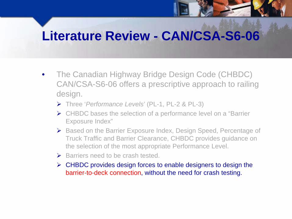
• The Canadian Highway Bridge Design Code (CHBDC) CAN/CSA-S6-06 offers a prescriptive approach to railing design.

Literature Review - CAN/CSA-S6-06
• The Canadian Highway Bridge Design Code (CHBDC) CAN/CSA-S6-06 offers a prescriptive approach to railing design. Three ‘Performance Levels’ (PL-1, PL-2 & PL-3)

Literature Review - CAN/CSA-S6-06
• The Canadian Highway Bridge Design Code (CHBDC) CAN/CSA-S6-06 offers a prescriptive approach to railing design. Three ‘Performance Levels’ (PL-1, PL-2 & PL-3) CHBDC bases the selection of a performance level on a “Barrier
Exposure Index” that accounts for: o Highway Type o Highway Curvature o Highway Grade o Superstructure Height (crossing land or water) o Annual Average Daily Traffic (AADT)
Literature Review - CAN/CSA-S6-06
• The Canadian Highway Bridge Design Code (CHBDC) CAN/CSA-S6-06 offers a prescriptive approach to railing design. Three ‘Performance Levels’ (PL-1, PL-2 & PL-3) CHBDC bases the selection of a performance level on a “Barrier
Exposure Index” Based on the Barrier Exposure Index, Design Speed, Percentage of
Truck Traffic and Barrier Clearance, CHBDC provides guidance on the selection of the most appropriate Performance Level.
Barriers need to be crash tested.
Literature Review - CAN/CSA-S6-06
• The Canadian Highway Bridge Design Code (CHBDC) CAN/CSA-S6-06 offers a prescriptive approach to railing design. Three ‘Performance Levels’ (PL-1, PL-2 & PL-3) CHBDC bases the selection of a performance level on a “Barrier
Exposure Index” Based on the Barrier Exposure Index, Design Speed, Percentage of
Truck Traffic and Barrier Clearance, CHBDC provides guidance on the selection of the most appropriate Performance Level.
Barriers need to be crash tested. CHBDC provides design forces to enable designers to design the
barrier-to-deck connection, without the need for crash testing.

Literature Review - CAN/CSA-S6-06
• The Canadian Highway Bridge Design Code (CHBDC) CAN/CSA-S6-06 offers a prescriptive approach to railing design. Three ‘Performance Levels’ (PL-1, PL-2 & PL-3) CHBDC bases the selection of a performance level on a “Barrier
Exposure Index” Based on the Barrier Exposure Index, Design Speed, Percentage of
Truck Traffic and Barrier Clearance, CHBDC provides guidance on the selection of the most appropriate Performance Level.
Barriers need to be crash tested. CHBDC provides design forces to enable designers to design the
barrier-to-deck connection, without the need for crash testing. Several Provincial Ministry's require the use of Standard Barrier
Details

Literature Review - CAN/CSA-S6-06
Supplement No. 3 (3013) to S6-06, incorporated a new ‘Low Volume Road Bridge Barrier (TL-1) for roads with:
• Widths ≤ 8.6 m • Deck height above ground or water surface ≤ 5.0 m • max AADT = 100 for max design speed of 80 km/h • max AADT = 400 for max design speed of 50 km/h

Literature Review - BC MoTI
• The British Columbia Ministry of Transport and Infrastructure (MoTI) provides some guidance on the use of bridge barriers for low volume roads in the “Low Volume Road Bridge Design Guidelines”.

Literature Review - BC MoTI
• The British Columbia Ministry of Transport and Infrastructure (MoTI) provides some guidance on the use of bridge barriers for low volume roads in the “Low Volume Road Bridge Design Guidelines”.
• The MoTI accepts crash tested ‘Test Level 1’ (TL-1) barriers when: ADT ≤ 50. Deck height above the channel bottom ≤ 4.0 m. Operating speed ≤ 50 km/hr. Bridge width < 8.5 m.

Literature Review - Ontario
The Ontario Ministry of Transport (MTO) offers some guidance on the use of barriers with performance levels less than that mandated by CHBDC, for low-volume, low-speed, and low-hazard bridges.

Literature Review - Ontario
The Ontario Ministry of Transport (MTO) offers some guidance on the use of barriers with performance levels less than that mandated by CHBDC, for low-volume, low-speed, and low-hazard bridges.
The MTO defines two levels of barriers, LVPL1 and LVPL2 for consideration on low volume roads, based on AADT, Deck Height, Design Speed and Bridge Width.
LVPL 2 (TL-1)
LVPL 1 (sub TL-1)

Literature Review - Ontario
The Ontario Ministry of Transport (MTO) offers some guidance on the use of barriers with performance levels less than that mandated by CHBDC, for low-volume, low-speed, and low-hazard bridges.
The MTO defines two levels of barriers, LVPL1 and LVPL2 for consideration on low volume roads, based on AADT, Deck Height, Design Speed and Bridge Width.
MTO provides standard drawings for approved barrier configurations.

Literature Review - Ontario
The Ontario Ministry of Transport (MTO) offers some guidance on the use of barriers with performance levels less than that mandated by CHBDC, for low-volume, low-speed, and low-hazard bridges.
The MTO defines two levels of barriers, LVPL1 and LVPL2 for consideration on low volume roads, based on AADT, Deck Height, Design Speed and Bridge Width.
MTO provides standard drawings for approved barrier configurations. The Ontario Ministry of Natural Resources (MNR) provides guidance
on the use of bridge barriers for forestry and resource roads in “Crown Land Bridge Management Guidelines”.
The document states that “curbs and railings need not be designed to withstand live loads specified in the Bridge Code. They are intended to mark the edge of the bridge deck and need not be designed to deflect an impacting vehicle”.
MNR provides standard drawings for approved barrier configurations.

Literature Review - MFLNRO (pre-research & development outlined in this presentation).
• The Ministry's ‘Forest Service Bridge Design and Construction Manual’ and ‘Interim MFR Bridge Design Guidelines’ provides limited guidance on barrier design for forestry roads.

Literature Review - MFLNRO (pre-research & development outlined in this presentation).
• The Ministry's ‘Forest Service Bridge Design and Construction Manual’ and ‘Interim MFR Bridge Design Guidelines’ provides limited guidance on barrier design for forestry roads. Bridge rails must conform to one of three standard design options
o Timber Curbs o W-Beam o HSS Beam
HSS BEAM W-Beam Timber Curb

Literature Review - MFLNRO (pre-research & development outlined in this presentation).
• The Ministry's ‘Forest Service Bridge Design and Construction Manual’ and ‘Interim MFR Bridge Design Guidelines’ provides limited guidance on barrier design for forestry roads. Bridge rails must conform to one of three standard design options
o Timber Curbs o W-Beam o HSS Beam
Bridge design must conform to CHBDC, modified to suit forestry bridges.
They appear to be performing successfully, however, they have not been crash-tested, nor do they appear to meet the design and selection requirements of either the CHDBC or AASHTO LRFD.

Literature Review – AASHTO LRFD
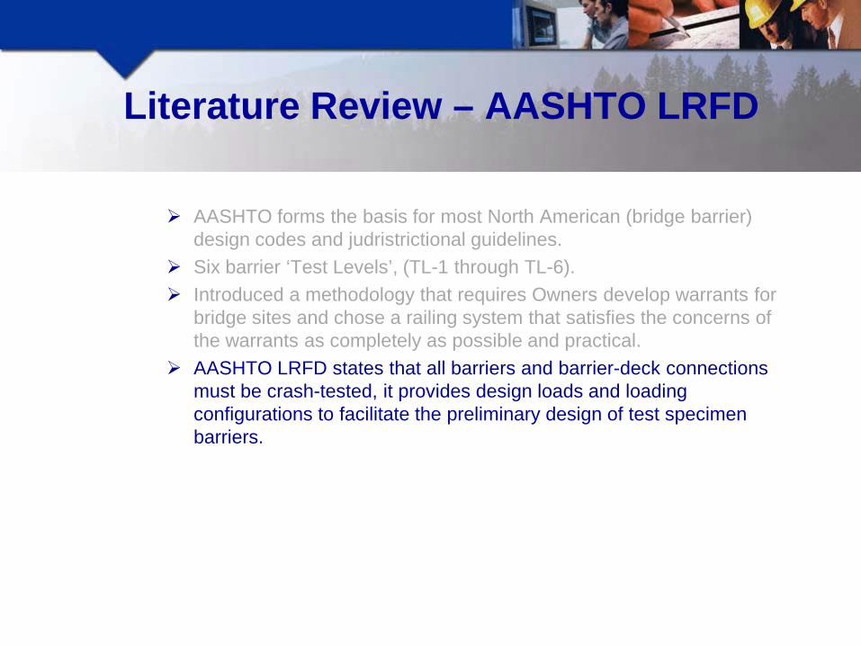
AASHTO forms the basis for most North American (bridge barrier) design codes and judristrictional guidelines.

Literature Review – AASHTO LRFD
AASHTO forms the basis for most North American (bridge barrier) design codes and judristrictional guidelines.
Six barrier ‘Test Levels’, (TL-1 through TL-6).
AASHTO CHBDC MFLNRO - - CL-1
TL-1 TL-1 CL-2 TL-2 PL-1 CL-3 TL-3 PL-2 - TL-4 - TL-5 PL-3 - TL-6 - -

Literature Review – AASHTO LRFD
AASHTO forms the basis for most North American (bridge barrier) design codes and judristrictional guidelines.
Six barrier ‘Test Levels’, (TL-1 through TL-6). Introduced a methodology that requires Owners develop warrants for
bridge sites and chose a railing system that satisfies the concerns of the warrants as completely as possible and practical.
AASHTO LRFD states that all barriers and barrier-deck connections must be crash-tested, it provides design loads and loading configurations to facilitate the preliminary design of test specimen barriers.

Literature Review – AASHTO Guidelines for Geometric Design of Very Low-Volume Local Roads (ADT≤400)
The guidelines introduce a basis for a risk management approach to barrier design.

Literature Review – US Forest Service Transportation Structures Handbook – 2011 (yet to be implemented)
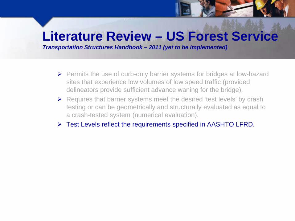
Permits the use of curb-only barrier systems for bridges at low-hazard sites that experience low volumes of low speed traffic (provided delineators provide sufficient advance waning for the bridge).

Literature Review – US Forest Service Transportation Structures Handbook – 2011 (yet to be implemented)
Permits the use of curb-only barrier systems for bridges at low-hazard sites that experience low volumes of low speed traffic (provided delineators provide sufficient advance waning for the bridge).
Requires that barrier systems meet the desired ‘test levels’ by crash testing or can be geometrically and structurally evaluated as equal to a crash-tested system (numerical evaluation).
Test Levels reflect the requirements specified in AASHTO LFRD.

Literature Review – US Forest Service Transportation Structures Handbook – 2011 (yet to be implemented)
Permits the use of curb-only barrier systems for bridges at low-hazard sites that experience low volumes of low speed traffic (provided delineators provide sufficient advance waning for the bridge).
Requires that barrier systems meet the desired ‘test levels’ by crash testing or can be geometrically and structurally evaluated as equal to a crash-tested system (numerical evaluation).
Test Levels reflect the requirements specified in AASHTO LFRD. Criteria that effect barrier selection include routes traffic volume, traffic
type, speed, lane properties and pavement type.

Proposed Barrier Selection Guidelines
Most regulatory agencies require the installation of TL-1 or TL-2 performance level barriers on low-volume roads.

Proposed Barrier Selection Guidelines
Most regulatory agencies require the installation of TL-1 or TL-2 performance level barriers on low-volume roads.
Risk based approach most suitable for the Ministry's “Barrier Selection Guidelines’ (similar to AASHTO’s “Guidelines for Geometric Design of Very Low-Volume Local Roads (ADT≤400)”.
It is not economically feasible to contain industrial trucks, but the risk of barrier collision is significantly reduced for professionally trained driver who are familiar with low-volume forestry roads.
Its recognized that the Ministry's standard bridge barriers appear to be performing adequately and provide an acceptable level of containment.

Proposed Barrier Selection Guidelines
In developing a risk-based evaluation and selection criteria, the Ministry will need to assess the risks associated with the following factors at each bridge location: o Anticipated Traffic Volume o Anticipated Traffic Mix o Horizontal and Vertical Alignment o Speed o Height o Bridge Widths o Environmental Conditions and Seasonality o Pedestrians

Proposed Barrier Selection Guidelines
Anticipated Traffic Volume o The higher the traffic volumes, the higher the probability that a
vehicle will impact the bridge barrier. o Typical limits for low volume roads are an ADT ≤ 400 vehicles per
day o Most forestry roads experience significantly less than 400
vehicles per day.

Proposed Barrier Selection Guidelines
In developing a risk-based evaluation and selection criteria, the Ministry will need to assess the risks associated with the following factors at each bridge location: o Anticipated Traffic Volume o Anticipated Traffic Mix o Horizontal and Vertical Alignment o Speed o Height o Bridge Widths o Environmental Conditions and Seasonality o Pedestrians

Proposed Barrier Selection Guidelines
Anticipated Traffic Mix o Where public access is limited, road users may be familiar with
the road and associated travel conditions. o Operators of these roads will likely have safety protocol in place
that governs the use of the road, therefore be appropriate to accept a lower level of containment.
o On roads where the Ministry anticipate a higher proportion of public traffic, we recommend consideration be given to providing a higher level of containment.

Proposed Barrier Selection Guidelines
In developing a risk-based evaluation and selection criteria, the Ministry will need to assess the risks associated with the following factors at each bridge location: o Anticipated Traffic Volume o Anticipated Traffic Mix o Horizontal and Vertical Alignment o Speed o Height o Bridge Widths o Environmental Conditions and Seasonality o Pedestrians
Proposed Barrier Selection Guidelines
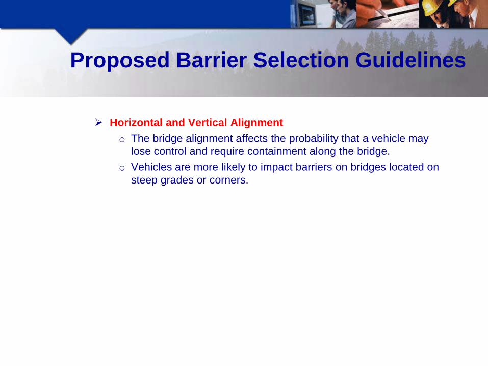
Horizontal and Vertical Alignment o The bridge alignment affects the probability that a vehicle may
lose control and require containment along the bridge. o Vehicles are more likely to impact barriers on bridges located on
steep grades or corners.

Proposed Barrier Selection Guidelines
In developing a risk-based evaluation and selection criteria, the Ministry will need to assess the risks associated with the following factors at each bridge location: o Anticipated Traffic Volume o Anticipated Traffic Mix o Horizontal and Vertical Alignment o Speed o Height o Bridge Widths o Environmental Conditions and Seasonality o Pedestrians

Proposed Barrier Selection Guidelines
Speed o Where the Ministry anticipates higher travel speeds, it may be
appropriate to consider providing higher levels of containment. o Typical limiting traffic speeds for low volume or industrial roads
before increased levels of containment are required range from 50-60 km/hr.

Proposed Barrier Selection Guidelines
In developing a risk-based evaluation and selection criteria, the Ministry will need to assess the risks associated with the following factors at each bridge location: o Anticipated Traffic Volume o Anticipated Traffic Mix o Horizontal and Vertical Alignment o Speed o Height o Bridge Widths o Environmental Conditions and Seasonality o Pedestrians

Proposed Barrier Selection Guidelines
Height o Where the bridge is located above a water body, ravine or
another roadway/railway (overpass), the Ministry should consider the consequence to both the driver and surrounding environment if the vehicle breaches the barrier.
o Typical limiting heights above water before increased levels of containment are required range from 2.5-5.0 m.

Proposed Barrier Selection Guidelines
In developing a risk-based evaluation and selection criteria, the Ministry will need to assess the risks associated with the following factors at each bridge location: o Anticipated Traffic Volume o Anticipated Traffic Mix o Horizontal and Vertical Alignment o Speed o Height o Bridge Widths o Environmental Conditions and Seasonality o Pedestrians
Proposed Barrier Selection Guidelines
Bridge Widths o Typically, the angle of incidence for a vehicle striking a barrier on
a single lane bridge is low resulting in reduced containment forces.
o As the bridge width increases, the angle of incidence increases resulting in higher containment forces. Thus, the Ministry should consider providing higher levels of containment on wider or multi-lane bridges.
Proposed Barrier Selection Guidelines
In developing a risk-based evaluation and selection criteria, the Ministry will need to assess the risks associated with the following factors at each bridge location: o Anticipated Traffic Volume o Anticipated Traffic Mix o Horizontal and Vertical Alignment o Speed o Height o Bridge Widths o Environmental Conditions and Seasonality o Pedestrians

Proposed Barrier Selection Guidelines
Environmental Conditions and Seasonality o The Ministry should consider local conditions that may affect
bridge deck or road approach conditions. These may include bridges that may receive limited sunlight and remain icy for significant portion of the day resulting in an increased likelihood of an accident on the bridge or its approaches.
o Where this presents a risk, the Ministry should consider providing higher levels of containment.

Proposed Barrier Selection Guidelines
In developing a risk-based evaluation and selection criteria, the Ministry will need to assess the risks associated with the following factors at each bridge location: o Anticipated Traffic Volume o Anticipated Traffic Mix o Horizontal and Vertical Alignment o Speed o Height o Bridge Widths o Environmental Conditions and Seasonality o Pedestrians

Proposed Barrier Selection Guidelines
Pedestrians o Where the Ministry expects that a large number of pedestrians
will use a bridge, the Ministry should consider providing pedestrian height rails and possibly providing increased levels of containment.
o Alternatives may also include a separated sidewalk or the inclusion of pedestrian refuges on longer bridges.

Containment Levels
We proposed three Containment Levels:
Containment Levels
We proposed three Containment Levels: o Containment Level 1 (CL-1) – Bridges that display the following
characteristics: o Exclusively industrial traffic and minimal public traffic o Relatively low height above water/hazard. o Good vertical and horizontal alignment. o No pedestrian traffic. o Normal operating speeds

Containment Levels
We proposed three Containment Levels: o Containment Level 1 (CL-1) o Containment Level 2 (CL-2) – Bridges that display one or more of
the following characteristics: o Limited use by the public and pedestrians – users who may be unfamiliar with
the route o and associated hazards. o Significant height above water and/or near a significant hazard. o Adverse geometry and / or visibility. o Increased deck width. o Increased operating speeds.
Containment Levels
We proposed three Containment Levels: o Containment Level 1 (CL-1) o Containment Level 2 (CL-2) o Containment Level 3 (CL-3) – Bridges that display one or more of
the following characteristics: o High level of public and / or pedestrian use (may provide access to recreation
destinations, or rural communities, and may see a significant proportion of drivers who are unfamiliar with the driving conditions.
o Significant height above water. o Adverse geometry and / or visibility. o Increased deck width or multi-lane bridge. o High operating speeds.

Containment Levels
We proposed three Containment Levels: o Containment Level 1 (CL-1) o Containment Level 2 (CL-2) o Containment Level 3 (CL-3)
To facilitate the selection of an appropriate barrier (that provides
sufficient containment), we proposed a decision flowchart to determine to the required level of containment.

Bridge Barrier Decision Flowchart
Traffic Mix - Mixture of industrial and public traffic.
Type 1: Exclusively Industrial vehicle traffic
Bridge Deck Height - Measured from the top of the bridge deck to the top of the water or ground below.
Design Speed
Bridge Deck Width - Measured between inside of curbs.
Containment Level
Notes: 1.) The Ministry to develop traffic volumes X and Y.2.) Where pedestrian use is expected, consider installing barrier-top rails to achieve a total height of 1070 mm.3.) Where vertical grade exceeds the area-specific average (eg. > 4%), apply engineering judgement to determine whether a higher standard barrier is appropriate.
Bridge Deck height < 5.0 m above waterway or other
hazard
Bridge Deck height < 10.0 m above waterway or other hazard
Bridge Barrier Decision Flowchart
Type 2: < X VPD Predominantly industrial
vehicle traffic
Type 3: < Y VPD Mostly industrial vehicle traffic,
limited public mix
Type 4: ≥ Y VPD Primarily public traffic
Containment Level 3 (CL-3)
Design Speed < 50 km/h Design Speed < 80 km/h
Bridge Deck Width < 5.6 m Bridge Deck Width < 8.0 m
Containment Level 1 (CL-1) Containment Level 2 (CL-2)
Y
Y
Y
Y
Y
Y
N
N
N
N
N
N

Design Guidelines
Regulatory Agency Factored Design Criteria Containment Level - TL-1 TL-2
AASHTO LRFD 2010
Transverse Load (kN) - 60 120 Longitudinal Load (kN) - 20 40 Vertical Load (kN) - 20 20 Load Application Height (mm) - 460 510
- TL-1 PL-1
CHBDC (S6-06)
Transverse Load (kN) - 25 85 Longitudinal Load (kN) - 10 34 Vertical Load (kN) - 10 17 Load Application Height (mm) - 600 600
Modified CHBDC S6-06 Transverse Load (kN) - - 119 CL-1 CL-2 CL-3
Proposed BC MFLNRO
Transverse Load (kN) - 60 120 Longitudinal Load (kN) - 20 40 Vertical Load (kN) - 20 20 Load Application Height (mm) - 450 510
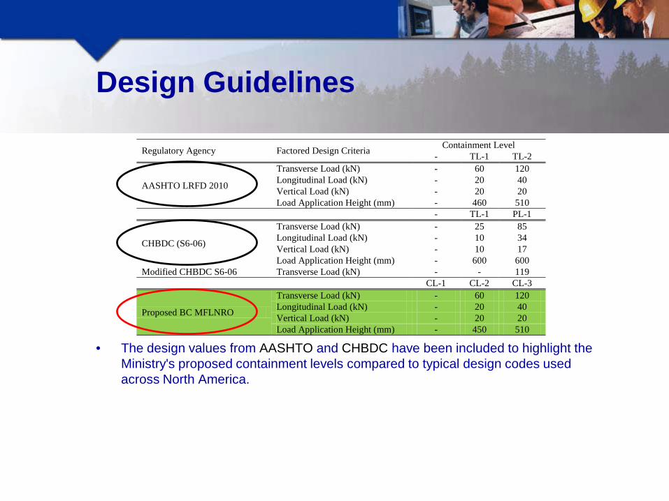
• The design values from AASHTO and CHBDC have been included to highlight the Ministry's proposed containment levels compared to typical design codes used across North America.
Design Guidelines
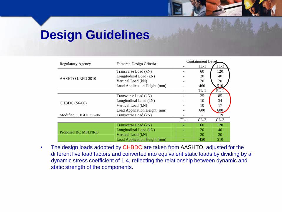
• The design loads adopted by CHBDC are taken from AASHTO, adjusted for the different live load factors and converted into equivalent static loads by dividing by a dynamic stress coefficient of 1.4, reflecting the relationship between dynamic and static strength of the components.
Regulatory Agency Factored Design Criteria Containment Level - TL-1 TL-2
AASHTO LRFD 2010
Transverse Load (kN) - 60 120 Longitudinal Load (kN) - 20 40 Vertical Load (kN) - 20 20 Load Application Height (mm) - 460 510
- TL-1 PL-1
CHBDC (S6-06)
Transverse Load (kN) - 25 85 Longitudinal Load (kN) - 10 34 Vertical Load (kN) - 10 17 Load Application Height (mm) - 600 600
Modified CHBDC S6-06 Transverse Load (kN) - - 119 CL-1 CL-2 CL-3
Proposed BC MFLNRO
Transverse Load (kN) - 60 120 Longitudinal Load (kN) - 20 40 Vertical Load (kN) - 20 20 Load Application Height (mm) - 450 510
Design Guidelines
• CL-1 barriers are expected to provide a lower levels of containment than AASHTO’s TL-1 and CHBDC’s TL-1 barriers.

Regulatory Agency Factored Design Criteria Containment Level - TL-1 TL-2
AASHTO LRFD 2010
Transverse Load (kN) - 60 120 Longitudinal Load (kN) - 20 40 Vertical Load (kN) - 20 20 Load Application Height (mm) - 460 510
- TL-1 PL-1
CHBDC (S6-06)
Transverse Load (kN) - 25 85 Longitudinal Load (kN) - 10 34 Vertical Load (kN) - 10 17 Load Application Height (mm) - 600 600
Modified CHBDC S6-06 Transverse Load (kN) - - 119 CL-1 CL-2 CL-3
Proposed BC MFLNRO
Transverse Load (kN) - 60 120 Longitudinal Load (kN) - 20 40 Vertical Load (kN) - 20 20 Load Application Height (mm) - 450 510
Design Guidelines
• CL-1 barriers are expected to provide a lower levels of containment than AASHTO’s TL-1 barriers.
• CL-2 barriers near identical to the requirements of AASHTO’s TL-1 barrier.

Design Guidelines
• CL-1 barriers are expected to provide a lower levels of containment than AASHTO’s TL-1 barriers.
• CL-2 barriers near identical to the requirements of AASHTO’s TL-1 barrier.
• CL-3 barriers near identical to the requirements of AASHTO’s TL-2 and CHBDC’s ‘modified’ PL-1 barriers.
Regulatory Agency Factored Design Criteria Containment Level - TL-1 TL-2
AASHTO LRFD 2010
Transverse Load (kN) - 60 120 Longitudinal Load (kN) - 20 40 Vertical Load (kN) - 20 20 Load Application Height (mm) - 460 510
- TL-1 PL-1
CHBDC (S6-06)
Transverse Load (kN) - 25 85 Longitudinal Load (kN) - 10 34 Vertical Load (kN) - 10 17 Load Application Height (mm) - 600 600
Modified CHBDC S6-06 Transverse Load (kN) - - 119 CL-1 CL-2 CL-3
Proposed BC MFLNRO
Transverse Load (kN) - 60 120 Longitudinal Load (kN) - 20 40 Vertical Load (kN) - 20 20 Load Application Height (mm) - 450 510

Testing Existing Barrier Configurations
• The University of British Columbia (UBC) tested the Ministry’s existing barrier configurations to determine the static lateral capacity of the barrier and/or barrier anchorage to typical Ministry concrete deck panels.
Testing Existing Barrier Configurations
• The University of British Columbia (UBC) tested the Ministry’s existing barrier configurations to determine the static lateral capacity of the barrier and/or barrier anchorage to typical Ministry concrete deck panels.
• It should be noted that some of the following information is not presented in chronological order, the nature of the work involved multiple revisions and phases of testing. The material is presented in a manner that groups similar test together to enable the viewers to visualize the results as a whole.

Experimental Set-Up
Existing Barrier - Results
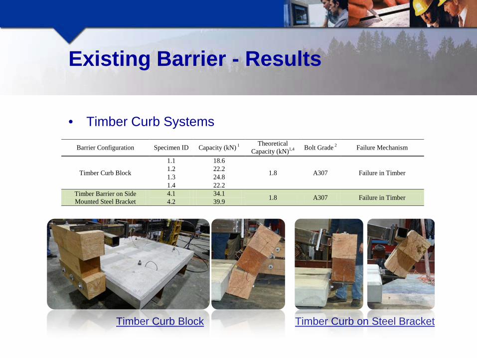
• Timber Curb Systems
Timber Curb Block Timber Curb on Steel Bracket
Barrier Configuration Specimen ID Capacity (kN) 1 Theoretical Capacity (kN)1,4 Bolt Grade 2 Failure Mechanism
Timber Curb Block
1.1 18.6
1.8 A307 Failure in Timber 1.2 22.2 1.3 24.8 1.4 22.2
Timber Barrier on Side Mounted Steel Bracket
4.1 34.1 1.8 A307 Failure in Timber 4.2 39.9

Timber Curb Block - Test Video

Classifying Timber Curb Barriers
• The experimental values for the Timber Curbs shown below.
It is difficult to determine the capacity of timber barriers numerically.
Barrier Configuration Specimen ID Capacity (kN) 1 Theoretical Capacity (kN)1,4 Bolt Grade 2 Failure Mechanism
Timber Curb Block
1.1 18.6
1.8 A307 Failure in Timber 1.2 22.2 1.3 24.8 1.4 22.2
Timber Barrier on Side Mounted Steel Bracket
4.1 34.1 1.8 A307 Failure in Timber 4.2 39.9

Classifying Timber Curb Barriers
• The experimental values for the Timber Curbs shown below.
It is difficult to determine the capacity of timber barriers numerically. The tested capacities offer minimal lateral resistance (AASHTO’s TL-1 = 60kN).
• As Timber Curbs are performing adequately in the field, the Ministry opted to classify them as CL-1 barriers, but; Provide no design forces for CL-1 barriers in the ‘Factored Barrier Design Force’ table. Provide ‘Standard Drawing’s which must be used by designers for CL-1 specified bridge
barriers.
Barrier Configuration Specimen ID Capacity (kN) 1 Theoretical Capacity (kN)1,4 Bolt Grade 2 Failure Mechanism
Timber Curb Block
1.1 18.6
1.8 A307 Failure in Timber 1.2 22.2 1.3 24.8 1.4 22.2
Timber Barrier on Side Mounted Steel Bracket
4.1 34.1 1.8 A307 Failure in Timber 4.2 39.9

Existing Barrier - Results
• Top and/or Side Mounted Steel Bracket Systems
Side Mounted Steel Bracket Top & Side Mounted Steel Bracket
Barrier Configuration Specimen ID Experimental Capacity (kN) 1
Theoretical Capacity (kN)1 Bolt Grade 2 Failure Mechanism
Side-Mounted HSS Barrier (680mm Connection Bracket)
2.1 60.6
47 A307 Bracket Bolts Rupture in Tension
2.2 62.1 2.3 53.3 2.4 51.9
2.11 64.3 51 A325 Spalling of the Concrete in the Vicinity of the Inserts 2.21 54.1
Top & Side-Mounted HSS Barrier (680mm Connection Bracket)
3.1 47.3
N/A A307 Deck Fails in Block Shear 3.2 64.9 3.3 63.5 3.4 55.1
Side-Mounted Steel Bracket- Test Video

Classifying Side-Mounted Steel Bracket
• The experimental values for the Side-Mounted Steel Bracket are shown:
The numerical resistance consistently underestimates the bracket capacity.
Barrier Configuration Specimen ID Experimental Capacity (kN) 1
Theoretical Capacity (kN)1 Bolt Grade 2 Failure Mechanism
Side-Mounted HSS Barrier (680mm Connection Bracket)
2.1 60.6
47 A307 Bracket Bolts Rupture in Tension
2.2 62.1 2.3 53.3 2.4 51.9
2.11 64.3 51 A325 Spalling of the Concrete in the Vicinity of the Inserts 2.21 54.1

Classifying Side-Mounted Steel Bracket
• The experimental values for the Side-Mounted Steel Bracket are shown:
The numerical resistance consistently underestimates the bracket capacity. The bracket appears to be capable of achieving a 60 kN lateral resistance.
Barrier Configuration Specimen ID Experimental Capacity (kN) 1
Theoretical Capacity (kN)1 Bolt Grade 2 Failure Mechanism
Side-Mounted HSS Barrier (680mm Connection Bracket)
2.1 60.6
47 A307 Bracket Bolts Rupture in Tension
2.2 62.1 2.3 53.3 2.4 51.9
2.11 64.3 51 A325 Spalling of the Concrete in the Vicinity of the Inserts 2.21 54.1

Classifying Side-Mounted Steel Bracket
• The experimental values for the Side-Mounted Steel Bracket are shown:
The numerical resistance consistently underestimates the bracket capacity. The bracket appears to be capable of achieving a 60 kN lateral resistance. A variation in bolt grade changes the failure mechanism.
• Based on the results, the Side-Mounted Steel Bracket was classified as a CL-2 barrier, and; ‘Standard Drawing’s were provided by the Ministry for CL-2 specified bridge barriers. Design forces were to be included in the ‘Factored Barrier Design Force’ table to permit
designers to create alternate CL-2 barrier details.
Barrier Configuration Specimen ID Experimental Capacity (kN) 1
Theoretical Capacity (kN)1 Bolt Grade 2 Failure Mechanism
Side-Mounted HSS Barrier (680mm Connection Bracket)
2.1 60.6
47 A307 Bracket Bolts Rupture in Tension
2.2 62.1 2.3 53.3 2.4 51.9
2.11 64.3 51 A325 Spalling of the Concrete in the Vicinity of the Inserts 2.21 54.1

Side-Mounted Barrier Modifications
• Side Mounted Steel Bracket with Knee-Brace Modification During the original testing phase, UBC, at its own accord, modified
the Side-Mounted HSS Barrier by adding a 600 mm long knee-brace, which projected under the concrete deck and engaged the girder flange.
The photographs present the modified HSS Barrier with the knee-brace extending under the deck edge.
Side Mounted Steel Bracket with Knee-Brace Modification

Knee-Braced Barrier - Results
• Side Mounted Steel Bracket with Knee-Brace Modification
The experimental results for the modified Side-Mounted HSS Barrier
are shown in the above Table. This modification resulted in the barrier capacity increasing by
approximately 230% (compared to the Side-Mounted HSS Barrier). Modifications resulted in the barrier achieving the minimum required
lateral resistance for a CL-3 classification barrier.
Barrier Configuration Specimen ID Capacity (kN) 1 Bolt Grade 2 Failure Mechanism
Modified Side-Mounted HSS Barrier (knee-brace)
4.3 154.8 A307 Concrete Failure at Panel
Edge 4.4 124.1 4.5 164.4
1 Capacities are based on a load application height of 450mm above the travelled surface. 2 Bolt grade for bracket-to-deck connection only. 3 Concrete compressive strength (f’c) = 56 MPa.

Knee-Brace Modification- Test Video

Implication of Knee-Brace Modification
• On review of the experimental data and specimen configuration it was established that a knee-brace of this length (600 mm) was impractical for field installations, since the knee-brace would rest on the girder flange making installation and accommodation of field tolerances difficult.
• A review of typical steel girder and concrete deck forestry bridges (in BC) suggests that the maximum practical lever arm is 300-400 mm, which results in an increased demand on the anchor bolts.
• Analysis concluded that a 400 mm knee-brace would result in an approximate transverse load capacity of 98 kN, which suggests that it does not meet the requirements for a CL-3 barrier, which requires a minimum of 120 kN.
• As a result, the Ministry opted to conduct a further development and experimental investigation to develop a new side-mounted barrier capable of achieving the design requirements for a CL-3 barrier, the details of which are discussed in the upcoming sections.

Conclusions of Phase 1 Testing
• Timber Curbs & W-Beams classified as CL-1 barrier Design forces excluded from the ‘Factored Barrier Design Force’ table Designers only permitted to use Ministry standard drawings for CL-1 barriers

Conclusions of Phase 1 Testing
• Timber Curbs & W-Beams classified as CL-1 barrier Design forces excluded from the ‘Factored Barrier Design Force’ table Designers only permitted to use Ministry standard drawings for CL-1 barriers
• Side-Mounted Steel Bracket HSS Barrier classified as CL-2 barrier Standard drawings provided by the Ministry for same Design forces provided to allow design of alternate systems and modifications to the rail.

Conclusions of Phase 1 Testing
• Timber Curbs & W-Beams classified as CL-1 barrier Design forces excluded from the ‘Factored Barrier Design Force’ table Designers only permitted to use Ministry standard drawings for CL-1 barriers
• Side-Mounted Steel Bracket HSS Barrier classified as CL-2 barrier Standard drawings provided by the Ministry for same Design forces provided to allow design of alternate systems and modifications to the rail. Panel concrete strength (56 MPa) high
o Conduct additional phase of testing to compare 40 MPa deck panel

Conclusions of Phase 1 Testing
• Timber Curbs & W-Beams classified as CL-1 barrier Design forces excluded from the ‘Factored Barrier Design Force’ table Designers only permitted to use Ministry standard drawings for CL-1 barriers
• Side-Mounted Steel Bracket HSS Barrier classified as CL-2 barrier Standard drawings provided by the Ministry for same Design forces provided to allow design of alternate systems and modifications to the rail. Panel concrete strength (56 MPa) high
o Conduct additional phase of testing to compare 40 MPa deck panel Drip groove (50 mm from deck edge) appeared to influence the panel edge capacity
o Relocate drip groove 300 mm from deck edge

Conclusions of Phase 1 Testing
• Timber Curbs & W-Beams classified as CL-1 barrier Design forces excluded from the ‘Factored Barrier Design Force’ table Designers only permitted to use Ministry standard drawings for CL-1 barriers
• Side-Mounted Steel Bracket HSS Barrier classified as CL-2 barrier Standard drawings provided by the Ministry for same Design forces provided to allow design of alternate systems and modifications to the rail. Panel concrete strength (56 MPa) high
o Conduct additional phase of testing to compare 40 MPa deck panel Drip groove (50 mm from deck edge) appeared to influence the panel edge capacity
o Relocate drip groove 300 mm from deck edge Grade A325 bolts result in panel edge failure (undesirable failure mechanism)
o Barrier failure requires the panel to be replaced Grade A307 bolts result in bolt failure
o Easier (& cheaper) replacement option o Use A307 bolts for Side-Mounted Steel Bracket HSS CL-2 barrier

Conclusions of Phase 1 Testing
• Timber Curbs & W-Beams classified as CL-1 barrier Design forces excluded from the ‘Factored Barrier Design Force’ table Designers only permitted to use Ministry standard drawings for CL-1 barriers
• Side-Mounted Steel Bracket HSS Barrier classified as CL-2 barrier Standard drawings provided by the Ministry for same Design forces provided to allow design of alternate systems and modifications to the rail. Panel concrete strength (56 MPa) high
o Conduct additional phase of testing to compare 40 MPa deck panel Drip groove (50 mm from deck edge) appeared to influence the panel edge capacity
o Relocate drip groove 300 mm from deck edge Grade A325 bolts result in panel edge failure (undesirable failure mechanism)
o Barrier failure requires the panel to be replaced Grade A307 bolts result in bolt failure
o Easier (& cheaper) replacement option o Use A307 bolts for Steel Bracket CL-2 barrier
Additional Modifications o Reduce bracket width from 680 mm to 550 mm o Incorporate bar anchors
Location of Bar Anchors

CL-2 Barrier – Tested Modifications
• Additional experimental phase with the following modifications to the CL-2 Side-Mounted HSS Barrier: 40 MPa panel concrete Drip groove located 300 mm from panel edge 550 mm and 680 mm wide bracket Grade A325 bolts used to ensure panel failure Bar anchors added to some specimens
550 mm & 680 mm TESTED
Grade A325 Bolts
Refined CL-2 Barrier Test Results
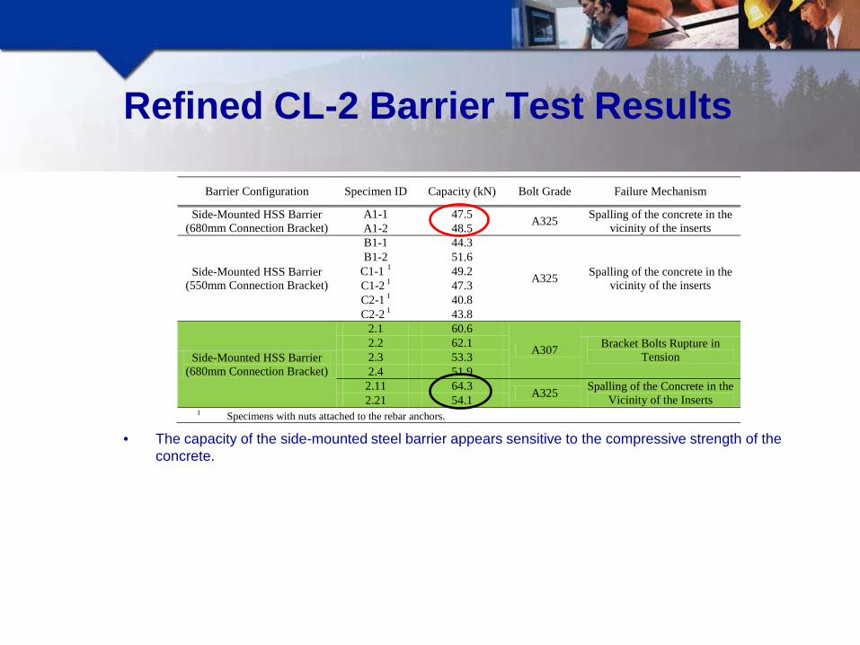
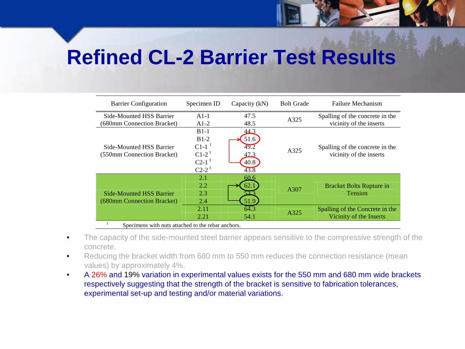
• The capacity of the side-mounted steel barrier appears sensitive to the compressive strength of the concrete.
Barrier Configuration Specimen ID Capacity (kN) Bolt Grade Failure Mechanism
Side-Mounted HSS Barrier (680mm Connection Bracket)
A1-1 47.5 A325 Spalling of the concrete in the vicinity of the inserts A1-2 48.5
Side-Mounted HSS Barrier (550mm Connection Bracket)
B1-1 44.3
A325 Spalling of the concrete in the vicinity of the inserts
B1-2 51.6 C1-1 1 49.2 C1-2 1 47.3 C2-1 1 40.8 C2-2 1 43.8
Side-Mounted HSS Barrier (680mm Connection Bracket)
2.1 60.6
A307 Bracket Bolts Rupture in Tension
2.2 62.1 2.3 53.3 2.4 51.9
2.11 64.3 A325 Spalling of the Concrete in the Vicinity of the Inserts 2.21 54.1
1 Specimens with nuts attached to the rebar anchors.

Refined CL-2 Barrier Test Results
• The capacity of the side-mounted steel barrier appears sensitive to the compressive strength of the concrete.
• Reducing the bracket width from 680 mm to 550 mm reduces the connection resistance (mean values) by approximately 4%.
Barrier Configuration Specimen ID Capacity (kN) Bolt Grade Failure Mechanism
Side-Mounted HSS Barrier (680mm Connection Bracket)
A1-1 47.5 A325 Spalling of the concrete in the vicinity of the inserts A1-2 48.5
Side-Mounted HSS Barrier (550mm Connection Bracket)
B1-1 44.3
A325 Spalling of the concrete in the vicinity of the inserts
B1-2 51.6 C1-1 1 49.2 C1-2 1 47.3 C2-1 1 40.8 C2-2 1 43.8
Side-Mounted HSS Barrier (680mm Connection Bracket)
2.1 60.6
A307 Bracket Bolts Rupture in Tension
2.2 62.1 2.3 53.3 2.4 51.9
2.11 64.3 A325 Spalling of the Concrete in the Vicinity of the Inserts 2.21 54.1
1 Specimens with nuts attached to the rebar anchors.
Refined CL-2 Barrier Test Results
• The capacity of the side-mounted steel barrier appears sensitive to the compressive strength of the concrete.
• Reducing the bracket width from 680 mm to 550 mm reduces the connection resistance (mean values) by approximately 4%.
• A 26% and 19% variation in experimental values exists for the 550 mm and 680 mm wide brackets respectively suggesting that the strength of the bracket is sensitive to fabrication tolerances, experimental set-up and testing and/or material variations.
Barrier Configuration Specimen ID Capacity (kN) Bolt Grade Failure Mechanism
Side-Mounted HSS Barrier (680mm Connection Bracket)
A1-1 47.5 A325 Spalling of the concrete in the vicinity of the inserts A1-2 48.5
Side-Mounted HSS Barrier (550mm Connection Bracket)
B1-1 44.3
A325 Spalling of the concrete in the vicinity of the inserts
B1-2 51.6 C1-1 1 49.2 C1-2 1 47.3 C2-1 1 40.8 C2-2 1 43.8
Side-Mounted HSS Barrier (680mm Connection Bracket)
2.1 60.6
A307 Bracket Bolts Rupture in Tension
2.2 62.1 2.3 53.3 2.4 51.9
2.11 64.3 A325 Spalling of the Concrete in the Vicinity of the Inserts 2.21 54.1
1 Specimens with nuts attached to the rebar anchors.

Refined CL-2 Barrier Test Results
• The capacity of the side-mounted steel barrier appears sensitive to the compressive strength of the concrete.
• Reducing the bracket width from 680 mm to 550 mm reduces the connection resistance (mean values) by approximately 4%.
• A 26% and 19% variation in experimental values exists for the 550 mm and 680 mm wide brackets respectively suggesting that the strength of the bracket is sensitive to fabrication tolerances, experimental set-up and testing and/or material variations.
• Improving the anchorage of the embedded reinforcing anchors does not increase the resistance of the barrier.
• The Side-Mounted HSS Barrier (additional tests) is unable to meet the proposed requirements of a CL-2 barrier (60 kN) when the concrete deck strength is 40 MPa.
Barrier Configuration Specimen ID Capacity (kN) Bolt Grade Failure Mechanism
Side-Mounted HSS Barrier (680mm Connection Bracket)
A1-1 47.5 A325 Spalling of the concrete in the vicinity of the inserts A1-2 48.5
Side-Mounted HSS Barrier (550mm Connection Bracket)
B1-1 44.3
A325 Spalling of the concrete in the vicinity of the inserts
B1-2 51.6 C1-1 1 49.2 C1-2 1 47.3 C2-1 1 40.8 C2-2 1 43.8
Side-Mounted HSS Barrier (680mm Connection Bracket)
2.1 60.6
A307 Bracket Bolts Rupture in Tension
2.2 62.1 2.3 53.3 2.4 51.9
2.11 64.3 A325 Spalling of the Concrete in the Vicinity of the Inserts 2.21 54.1
1 Specimens with nuts attached to the rebar anchors.
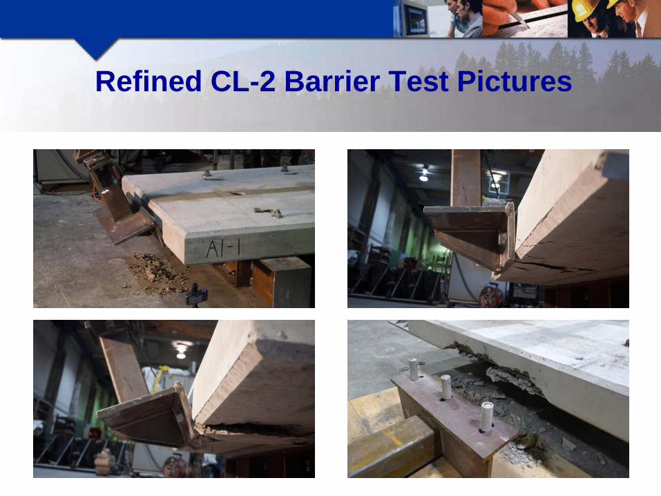
Refined CL-2 Barrier Test Pictures
Conclusions of Refined CL-2 Testing
• Based on the findings it was concluded that the Ministry should modify the existing Side-Mounted HSS Barrier standard drawing to:

Conclusions of Refined CL-2 Testing
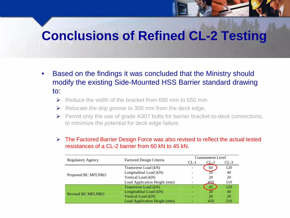
• Based on the findings it was concluded that the Ministry should modify the existing Side-Mounted HSS Barrier standard drawing to: Reduce the width of the bracket from 680 mm to 550 mm.

Conclusions of Refined CL-2 Testing
• Based on the findings it was concluded that the Ministry should modify the existing Side-Mounted HSS Barrier standard drawing to: Reduce the width of the bracket from 680 mm to 550 mm. Relocate the drip groove to 300 mm from the deck edge.

Conclusions of Refined CL-2 Testing
• Based on the findings it was concluded that the Ministry should modify the existing Side-Mounted HSS Barrier standard drawing to: Reduce the width of the bracket from 680 mm to 550 mm. Relocate the drip groove to 300 mm from the deck edge. Permit only the use of grade A307 bolts for barrier bracket-to-deck connections,
to minimize the potential for deck edge failure.
The Factored Barrier Design Force was also revised to reflect the actual tested resistances of a CL-2 barrier from 60 kN to 45 kN.
Regulatory Agency Factored Design Criteria Containment Level CL-1 CL-2 CL-3
Proposed BC MFLNRO
Transverse Load (kN) - 60 120 Longitudinal Load (kN) - 20 40 Vertical Load (kN) - 20 20 Load Application Height (mm) - 450 510
Revised BC MFLNRO
Transverse Load (kN) - 45 120 Longitudinal Load (kN) - 20 40 Vertical Load (kN) - 20 20 Load Application Height (mm) - 450 510
CL-3 Barrier Development
• A further development and experimental investigation was conducted to develop a new side-mounted barrier capable of achieving the design requirements for a CL-3 barrier. None of the standard or tested barriers are capable of achieving the proposed
CL-3 design criteria.

CL-3 Barrier Development
• A further development and experimental investigation was conducted to develop a new side-mounted barrier capable of achieving the design requirements for a CL-3 barrier. The results from the CL-2 tests indicated that the concrete in compression at the panel edge
was the limiting strength factor (assuming adequate connection between the barrier and deck panel was provided).
CL-3 Barrier Development
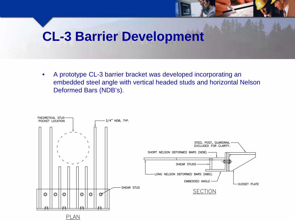
• A prototype CL-3 barrier bracket was developed incorporating an embedded steel angle with vertical headed studs and horizontal Nelson Deformed Bars (NDB’s).

CL-3 Barrier Development
• A prototype CL-3 barrier bracket was developed incorporating an embedded steel angle with vertical headed studs and horizontal Nelson Deformed Bars (NDB’s). The embedded angle and vertical studs confine the concrete along the edge of the panel
resulting in an increased compressive resistance.

CL-3 Barrier Development
• A prototype CL-3 barrier bracket was developed incorporating an embedded steel angle with vertical headed studs and horizontal Nelson Deformed Bars (NDB’s). The embedded angle and vertical studs confine the concrete along the edge of the panel
resulting in an increased compressive resistance. The horizontal NDB’s provide the required tensile resistance.

Prototype CL-3 Barrier- Test Video

CL-3 Barrier Test Results
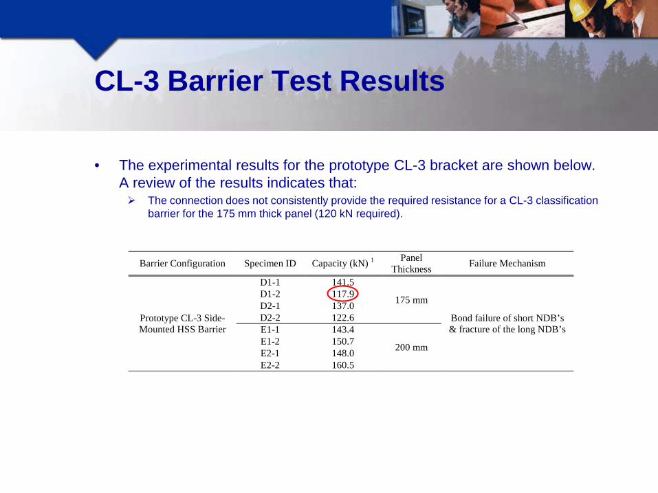
• The experimental results for the prototype CL-3 bracket are shown below. A review of the results indicates that:
Barrier Configuration Specimen ID Capacity (kN) 1 Panel Thickness Failure Mechanism
Prototype CL-3 Side-Mounted HSS Barrier
D1-1 141.5
175 mm
Bond failure of short NDB’s & fracture of the long NDB’s
D1-2 117.9 D2-1 137.0 D2-2 122.6 E1-1 143.4
200 mm E1-2 150.7 E2-1 148.0 E2-2 160.5
CL-3 Barrier Test Results
• The experimental results for the prototype CL-3 bracket are shown below. A review of the results indicates that: The connection does not consistently provide the required resistance for a CL-3 classification
barrier for the 175 mm thick panel (120 kN required).
Barrier Configuration Specimen ID Capacity (kN) 1 Panel Thickness Failure Mechanism
Prototype CL-3 Side-Mounted HSS Barrier
D1-1 141.5
175 mm
Bond failure of short NDB’s & fracture of the long NDB’s
D1-2 117.9 D2-1 137.0 D2-2 122.6 E1-1 143.4
200 mm E1-2 150.7 E2-1 148.0 E2-2 160.5
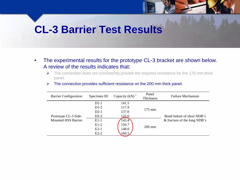
CL-3 Barrier Test Results
• The experimental results for the prototype CL-3 bracket are shown below. A review of the results indicates that: The connection does not consistently provide the required resistance for the 175 mm thick
panel. The connection provides sufficient resistance on the 200 mm thick panel.
Barrier Configuration Specimen ID Capacity (kN) 1 Panel Thickness Failure Mechanism
Prototype CL-3 Side-Mounted HSS Barrier
D1-1 141.5
175 mm
Bond failure of short NDB’s & fracture of the long NDB’s
D1-2 117.9 D2-1 137.0 D2-2 122.6 E1-1 143.4
200 mm E1-2 150.7 E2-1 148.0 E2-2 160.5
CL-3 Barrier Test Results
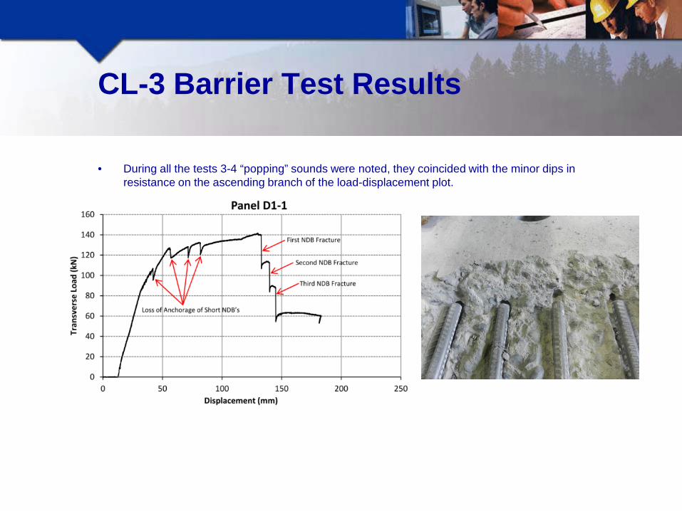
• During all the tests 3-4 “popping” sounds were noted, they coincided with the minor dips in resistance on the ascending branch of the load-displacement plot.

CL-3 Barrier Test Results
• During all the tests 3-4 “popping” sounds were noted, they coincided with the minor dips in resistance on the ascending branch of the load-displacement plot.
• Based on the load displacement plot and post-failure observations, it is believed that the “popping”
sounds were associated with the bond failure of the four short NDB’s.
• The connection achieved peak load after bond failure of the short NDB’s and prior to the fracture of one or more of the long NDB’s at the weld location. It is believed that if the short NDB’s had adequate anchorage (bond length), the connection may have achieved a higher peak resistance.

Modified CL-3 Barrier Configuration
• To increase the resistance of the prototype bracket, the four short NDB’s were replaced with four pairs of stacked headed studs.
Nelson Deformed Bars
Vertical Shear Studs
Stacked Studs
Short NDB’s removed

Modified CL-3 Barrier- Test Video

Modified CL-3 Barrier Test Results
• The above table includes the experimental results for both the Prototype and modified CL-3 bracket. The 175 and 200 mm deck panels are capable of consistently achieving the requirements of a
CL-3 barrier (120 kN).
Barrier Configuration Specimen ID Capacity (kN) 1 Panel Thickness Failure Mechanism
Prototype CL-3 Side-Mounted HSS Barrier
D1-1 141.5
175 mm
Bond failure of short NDB’s & fracture of the long NDB’s
D1-2 117.9 D2-1 137.0 D2-2 122.6 E1-1 143.4
200 mm E1-2 150.7 E2-1 148.0 E2-2 160.5
Modified CL-3 Side-Mounted HSS Barrier
G1-1 165.0 175 mm Flexural failure – top concrete cover failed resulting in loss of anchorage to the stacked studs
followed by concrete crushing in the vicinity of the inserts
G1-2 161.4 H1-1 193.0
200 mm H1-2 172.8

Modified CL-3 Barrier Test Results
• The above table includes the experimental results for both the Prototype and modified CL-3 bracket. The 175 and 200 mm deck panels are capable of consistently achieving the requirements of a
CL-3 barrier (120 kN). The modified CL-3 barrier connection failed due to yielding/pull-out of the stacked headed
studs and NDB’s, and the loss of the top cover concrete.
Barrier Configuration Specimen ID Capacity (kN) 1 Panel Thickness Failure Mechanism
Prototype CL-3 Side-Mounted HSS Barrier
D1-1 141.5
175 mm
Bond failure of short NDB’s & fracture of the long NDB’s
D1-2 117.9 D2-1 137.0 D2-2 122.6 E1-1 143.4
200 mm E1-2 150.7 E2-1 148.0 E2-2 160.5
Modified CL-3 Side-Mounted HSS Barrier
G1-1 165.0 175 mm Flexural failure – top concrete cover failed resulting in loss of anchorage to the stacked studs
followed by concrete crushing in the vicinity of the inserts
G1-2 161.4 H1-1 193.0
200 mm H1-2 172.8

Modified CL-3 Barrier Test Results
• The above table includes the experimental results for both the Prototype and modified CL-3 bracket. The 175 and 200 mm deck panels are capable of consistently achieving the requirements of a
CL-3 barrier (120 kN). The modified CL-3 barrier connection failed due to yielding/pull-out of the stacked headed
studs and NDB’s, and the loss of the top cover concrete. This was followed by the compressive failure of the concrete on the underside of the panel
and extensive rotation of the bracket.
Barrier Configuration Specimen ID Capacity (kN) 1 Panel Thickness Failure Mechanism
Prototype CL-3 Side-Mounted HSS Barrier
D1-1 141.5
175 mm
Bond failure of short NDB’s & fracture of the long NDB’s
D1-2 117.9 D2-1 137.0 D2-2 122.6 E1-1 143.4
200 mm E1-2 150.7 E2-1 148.0 E2-2 160.5
Modified CL-3 Side-Mounted HSS Barrier
G1-1 165.0 175 mm Flexural failure – top concrete cover failed resulting in loss of anchorage to the stacked studs
followed by concrete crushing in the vicinity of the inserts
G1-2 161.4 H1-1 193.0
200 mm H1-2 172.8

Modified CL-3 Barrier Test Results
• The above table includes the experimental results for both the Prototype and modified CL-3 bracket. The 175 and 200 mm deck panels are capable of consistently achieving the requirements of a
CL-3 barrier (120 kN). The modified CL-3 barrier connection failed due to yielding/pull-out of the stacked headed
studs and NDB’s, and the loss of the top cover concrete. This was followed by the compressive failure of the concrete on the underside of the panel
and extensive rotation of the bracket. The NDB’s did not fracture during any of the tests.
Barrier Configuration Specimen ID Capacity (kN) 1 Panel Thickness Failure Mechanism
Prototype CL-3 Side-Mounted HSS Barrier
D1-1 141.5
175 mm
Bond failure of short NDB’s & fracture of the long NDB’s
D1-2 117.9 D2-1 137.0 D2-2 122.6 E1-1 143.4
200 mm E1-2 150.7 E2-1 148.0 E2-2 160.5
Modified CL-3 Side-Mounted HSS Barrier
G1-1 165.0 175 mm Flexural failure – top concrete cover failed resulting in loss of anchorage to the stacked studs
followed by concrete crushing in the vicinity of the inserts
G1-2 161.4 H1-1 193.0
200 mm H1-2 172.8

CL-3 Failure Comparison
Panels D & E (only NDB reinforcement) Panels G & H (stacked studs & NDB reinforcement)

CL-3 Failure Comparison
Panels D & E (only NDB reinforcement) Panels G & H (stacked studs & NDB reinforcement)
Orientation of Panel Reinforcement
Orientation of Stacked Headed Studs Fractured NDB’s

CL-3 Load-Displacement Comparison
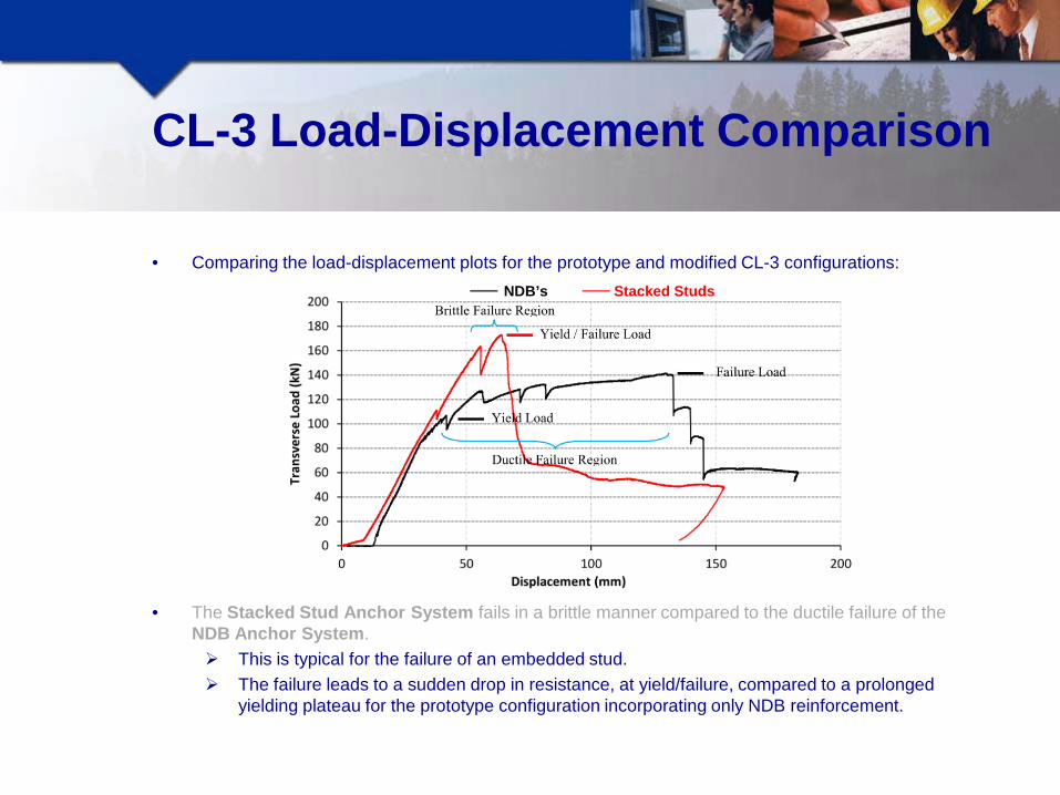
• Comparing the load-displacement plots for the prototype and modified CL-3 configurations:
• The Stacked Stud Anchor System fails in a brittle manner compared to the ductile failure of the NDB Anchor System.
Stacked Studs NDB’s
CL-3 Load-Displacement Comparison
• Comparing the load-displacement plots for the prototype and modified CL-3 configurations:
• The Stacked Stud Anchor System fails in a brittle manner compared to the ductile failure of the NDB Anchor System. This is typical for the failure of an embedded stud. The failure leads to a sudden drop in resistance, at yield/failure, compared to a prolonged
yielding plateau for the prototype configuration incorporating only NDB reinforcement.
Stacked Studs NDB’s

CL-3 Load-Displacement Comparison
• Comparing the load-displacement plots for the prototype and modified CL-3 configurations:
• The Stacked Stud Anchor System fails in a brittle manner compared to the ductile failure of the NDB Anchor System.
Brittle failure is not a concern if the post and rail assembly is designed to yield prior to failure of the bracket. The connection provides sufficient over-strength (> 120 kN), to facilitate the design of a post and rail assembly that will yield prior to failure of the embedded bracket.
Stacked Studs NDB’s

Conclusions of Modified CL-3 Testing
• Based on the findings a Standard Details Drawing for Side-Mounted CL-3 barriers was created for the Ministry incorporating the following:

Conclusions of Modified CL-3 Testing
• Based on the findings a Standard Details Drawing for Side-Mounted CL-3 barriers was created for the Ministry incorporating the following: A 680 mm wide bracket.

Conclusions of Modified CL-3 Testing
• Based on the findings a Standard Details Drawing for Side-Mounted CL-3 barriers was created for the Ministry incorporating the following: A 680 mm wide bracket. Grade A325 bolts for barrier bracket-to-deck connections.

Conclusions of Modified CL-3 Testing
• Based on the findings a Standard Details Drawing for Side-Mounted CL-3 barriers was created for the Ministry incorporating the following: A 680 mm wide bracket. Grade A325 bolts for barrier bracket-to-deck connections. An Embedded steel anchor identical to the Modified CL-3 details.

Conclusions of Modified CL-3 Testing
• Based on the findings a Standard Details Drawing for Side-Mounted CL-3 barriers was created for the Ministry incorporating the following: A 680 mm wide bracket. Grade A325 bolts for barrier bracket-to-deck connections. An Embedded steel anchor identical to the Modified CL-3 details. Drip groove located 300 mm from the deck edge.

CL-3 Barriers for Concrete Slab Bridges
• Based on the research discussed in this presentation a CL-3 barrier standard drawing was developed for concrete slab bridges.

CL-3 Barriers for Concrete Slab Bridges
• Based on the research discussed in this presentation a CL-3 barrier standard drawing was developed for concrete slab bridges. As slabs are typically 300 mm in depth, they provide considerably more depth to
resist the barrier loads than typical deck panel slabs (175-225 mm).
≈ 170 mm ≈ 55 mm
Typical Slab Typical Deck Panel

CL-3 Barriers for Concrete Slab Bridges
• Based on the research discussed in this presentation a CL-3 barrier standard drawing was developed for concrete slab bridges. As slabs are typically 300 mm in depth, they provide considerably more depth to
resist the barrier loads than typical deck panel slabs (175-225 mm). As discussed earlier, the limiting factor for concrete deck panel was the concrete
in compression at the panel edge (assuming adequate connection between the barrier and deck panel was provided).
≈ 170 mm ≈ 55 mm
Typical Slab Typical Deck Panel
Concrete Compression
Region Concrete
Compression Region
CL-3 Barriers for Concrete Slab Bridges
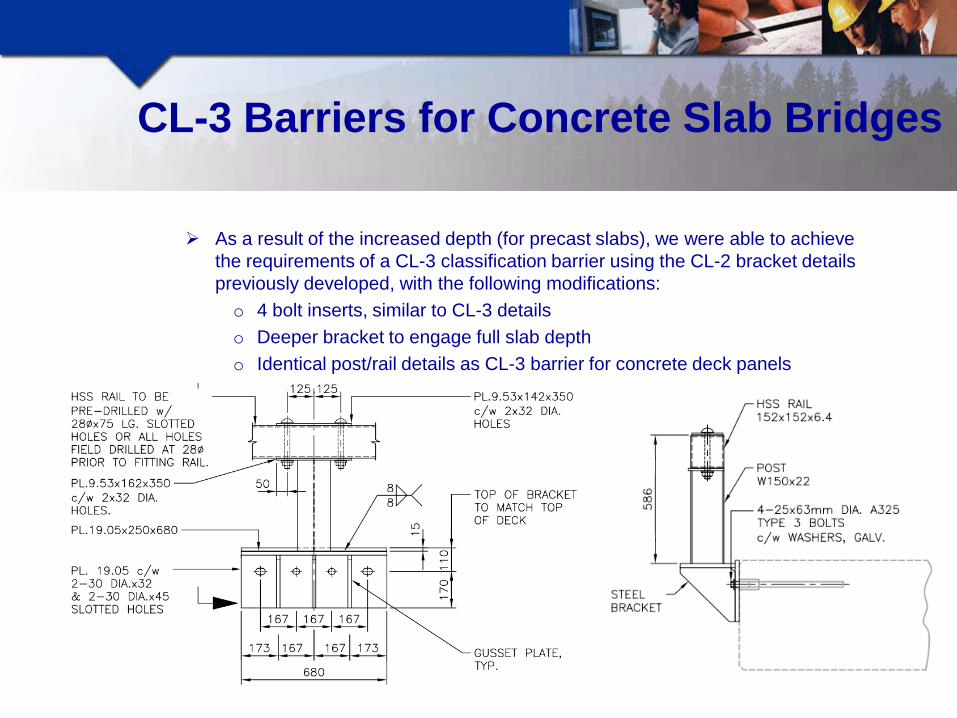
As a result of the increased depth (for precast slabs), we were able to achieve the requirements of a CL-3 classification barrier using the CL-2 bracket details previously developed, with the following modifications: o 4 bolt inserts, similar to CL-3 details o Deeper bracket to engage full slab depth o Identical post/rail details as CL-3 barrier for concrete deck panels

Acknowledgements
• The work presented in this presentation is part of an ongoing research and development assignment directed by Associated Engineering BC Ltd.
• The University of British Columbia (UBC) conducted all full-scale testing.
• The project was financed by the BC Ministry of Forests, Lands and Natural Recourse Operations (MFLNRO).
• The assistance from Prof. Sigi Stiemer, Brook Robazza and Grant Fraser is gratefully acknowledged in the development of this research.


Hawk-Eye !!!

Questions?