BRICKWORK MASONRY WALLS REINFORCED BY...
13
BRICKWORK MASONRY WALLS REINFORCED BY CFRP Roberto Capozucca 1 ABSTRACT The aim of this paper is the analysis of the behaviour of brickwork masonry walls damaged by shear-bending loading and reinforced by Carbon Fibre Polymers. The composite materials, FRP, applied at the surface of masonry permit acquiring tensile capacity and to avoid the cracking as a consequence of tensile weakness. In particular, masonry buildings may be damaged by seismic action that induces a tensile stresses. A typical failure of a masonry wall subjected to shear force is a flexural failure characterised by cracking at the tensioned side or crushing of masonry units at the compressed zone of wall. In this paper the author exams this case of failure considering experimental brickwork masonry models in 1 to 2 scale. After damage the brickwork model was reinforced by CFRP- sheets and subjected to the same path of loading. The experimental results obtained by the tests on the brickwork models are reported. Finally the comparison between the data of unreinforced and reinforced models leads to a number of considerations on the use of CFRP in repair works of masonry buildings. Key words: masonry model, shear-bending test, strengthening, CFRP-sheets. 1. Researcher and Lecturer Structural Department, University of Ancona, 60100 Ancona Italy ; e-mail: [email protected]
Transcript of BRICKWORK MASONRY WALLS REINFORCED BY...
BRICKWORK MASONRY WALLS REINFORCED BY CFRP
Roberto Capozucca 1
ABSTRACT The aim of this paper is the analysis of the behaviour of brickwork masonry walls damaged by shear-bending loading and reinforced by Carbon Fibre Polymers. The composite materials, FRP, applied at the surface of masonry permit acquiring tensile capacity and to avoid the cracking as a consequence of tensile weakness. In particular, masonry buildings may be damaged by seismic action that induces a tensile stresses. A typical failure of a masonry wall subjected to shear force is a flexural failure characterised by cracking at the tensioned side or crushing of masonry units at the compressed zone of wall. In this paper the author exams this case of failure considering experimental brickwork masonry models in 1 to 2 scale. After damage the brickwork model was reinforced by CFRP-sheets and subjected to the same path of loading. The experimental results obtained by the tests on the brickwork models are reported. Finally the comparison between the data of unreinforced and reinforced models leads to a number of considerations on the use of CFRP in repair works of masonry buildings. Key words: masonry model, shear-bending test, strengthening, CFRP-sheets. 1. Researcher and Lecturer Structural Department, University of Ancona, 60100 Ancona Italy ; e-mail:[email protected]

INTRODUCTION The strengthening of the masonry structures by materials with tensile capacity increases their strength and ductility. In recent years the researchers have attempted to attain this purpose utilising different techniques. An example of this is prestressed masonry (Sinha et al., 1992; Capozucca et al., 1999) where the steel is the material that permits obtaining an adequate behaviour under high bending loads. In recent years, the composite materials of Fibre Reinforced Polymers – FRP used as strengthening, has assumed a relevant position in the repair both of reinforced concrete and masonry. This technique was initially developed in Switzerland (Meier, 1987) and Germany (MPA, 1987). Many applications have been carried out on FRP to replace steel in RC structures or to strengthen damaged RC beams. Analytical models to predict the behaviour of RC beams strengthened with externally bonded FRP plates, evaluating the influence of different parameters were proposed (Saadatmanesh et al., 1991; An et al., 1991; Arduini et al., 1997). Currently the use of FRP-materials, consisting of epoxy resin as matrix and fibres, in the repair of masonry structures is increasing. Composite materials are suitable for repairing damaged masonry structures both with plane surfaces and curved surfaces (Triantafillou, 1998; Modena et al., 1999; Pascale et al., 2000; Capozucca et al., 2000). The principal advantages are the high strength-to-weight and stiffness-to-weight ratios, resistance to corrosion, easy applicability to existing structure and the possibility of tailoring to suit a particular application. The disadvantage is that FRP are expensive materials. A field of application of FRP is the strengthening of the masonry in seismic areas or in the repair of masonry walls damaged by an earthquake. During the last earthquake in Italy (1997-98), a large part of masonry buildings were damaged and destroyed. They showed a very low strength to seismic forces and an inadequate response. The collapse of parts of masonry buildings, or of the entire structure, was caused primarily by the low strength of material that does not permit attaining an adequate shear mechanism. Generally walls, either solid or with windows and door openings, represent the basic structural elements of a masonry structure, that resist seismic loads. When subjected to in-plane forces, the wall may fail in different modes, depending on its geometry and the seismic behaviour of the building: - sliding-shear failure or friction failure; - shear failure, which is characterised by diagonal cracks in the wall; - flexural failure, which is characterised by cracking in the tensioned side of a wall. The author exams the case of flexural failure and the technique with FRP in the repair. In seismic areas, the strengthening of masonry walls by FRP is a suitable technique. FRP-sheets are easily applied to the masonry wall and generally permit increasing the failure load to in-plane shear loading. However the behaviour of strengthened masonry walls is not yet completely known and different aspects have to be analysed. An object to study theoretically and experimentally is the mechanism of failure of in plane shear loading walls. The strengthening of masonry by FRP increases the strength value, but may lead to a mode of failure with local cracking on the units due to de-bonding of clay wall from the FRP-sheets. In this paper the behaviour of brickwork masonry walls damaged by shear-bending loading and strengthened by composite material of Carbon-FRP is analysed. The author exams two cases of strengthening by CFRP-sheets locally applied in regions particularly susceptible to damage as consequence of flexural failure. Experimental brickwork masonry models in scale 1 to 2 subjected to shear force were considered. The experimental results obtained by the tests carried out on the brickwork

models are reported and the comparison of the data involving unreinforced and reinforced models, leads to a number of considerations on the use of CFRP in the repair of masonry structures. EXPERIMENTAL MODEL
The experimental brickwork masonry model with flange is shown in Figure 1. The dimensions of the hollow units are 247x118x95mm3. The ratio of holes on the gross area is ϕ=45%. The wall subjected to bending and shear has a T-shape section. The principal dimensions are (Figure 2): t (width of wall)=118mm; b (depth of flange)=1.32m; h (height) = l (length) =1.47m. The section area is A=0.33m²; the position of the central axis from the edge of flange is a=477mm; the moment of inertia is I=831.53· 108mm4.
Figure 1 - Brickwork masonry model in scale 1 to 2.
l=1.47m t=118mm
h=1.47m
l=1.47m
Gb=1.32m
a =477mm
Figure 2 - Geometric dimensions of the brickwork model in scale 1 to 2.
The compression strength of the units in direction parallel to the holes is fb=22.45N/mm2. The mortar used in the wall is a high strength mortar, type M1 in compliance with Italian rules. The strength of mortar to compression is fm=19 N/mm2. The strength of masonry is evaluated both on prisms of 5 units and wallets of 504x515 mm2 in two directions, as shown in Figure 3(a). By means of compressive tests on the wallets, the compression

strength of masonry, f=12.86 N/mm2 , and the elastic modulus Ey=8483 N/mm2 by the diagram σ-ε (Figure 3b), are evaluated.
x
y
F
F
F F
Figure 3(a) - Masonry wallets subjected to compressive tests in two directions.
The values of shear strength fv0 in absence of vertical stress are experimentally evaluated by shear tests on triplets. The average experimental value is fv0 = 0.51 N/mm2 while the characteristic value is fvk0 = 0.7 fv0 equal to 0.35 N/mm2.
0
1
2
3
4
5
0 0.0002 0.0004 0.0006 0.0008
σy(N/mm2)
εy
Figure 3(b) - Cyclic diagrams by compressive tests on the wallets in y direction.
During the shear-bending test on the brickwork model, a precompression load was transferred on the top by RC slabs for a total of vertical stress σv = 0.1N/mm2. The test was cyclic and the horizontal load V was imposed by a hydraulic horizontal jack applied at the edge of slab (Figure 4 ).

GB(D) A(C)
E
F
1(4)2(3)
Vp
Figure 4 - Brickwork model and instruments of measure: E,F,G inductive displacement transducers; A,B,C,D inductive diagonal displacement transducers; 1,2,3,4 inductive displacement transducers at the first mortar bed joint.
BEHAVIOUR OF UNREINFORCED MODEL The behaviour of the model under shear load applied at the top is first studied theoretically considering the scheme in Figure 5. The unreinforced brickwork masonry model was subjected to a precompression load P so that a vertical stress is present in the wall: σv = P/A (1) Under loading, the tensile stress that may be sustained at the A point, located at the height of the first mortar joint, in absence of tensile capacity of the masonry, is equal to σv.
V x
y
a
l t
AG
h
σv = P/A
1
f =t σv
Figure 5 - Brickwork masonry scheme under loading.
The normal stress σA is due to bending and precompression:
x
1)M(A I
ahV ⋅⋅=σ (2)
A
P)N(A =σ (3)
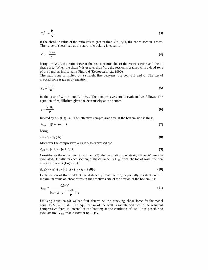
If the absolute value of the ratio P/A is greater than V⋅h1⋅as/ I, the entire section reacts. The value of shear load at the start of cracking is equal to:
1cr h
uVV
⋅= (4)
being u = Ws/A the ratio between the resistant modulus of the entire section and the T-shape area. When the shear V is greater than Vcr , the section is cracked with a dead zone of the panel as indicated in Figure 6 (Epperson et al., 1990). The dead zone is limited by a straight line between the points B and C. The top of cracked zone is given by equation:
V
uPy0
⋅= (5)
in the case of y0 < h1 and V > Vcr. The compressive zone is evaluated as follows. The equation of equilibrium gives the eccentricity at the bottom:
P
hVe 1⋅
= (6)
limited by e ≤ (l+t) - a. The effective compressive area at the bottom side is thus:
t]c)t1[(A eff ⋅−+= (7) being c = (h1 - y0 )⋅tgθ (8) Moreover the compressive area is also expressed by: Aeff =3⋅[(l+t) – (a + e)]⋅t (9) Considering the equations (7), (8), and (9), the inclination θ of straight line B-C may be evaluated. Finally for each section, at the distance y > y0 from the top of wall, the non cracked zone is (Figure 6): Aeff(y) = a(y)⋅t = [(l+t) – ( y - y0) ⋅ tgθ]⋅t (10) Each section of the model at the distance y from the top, is partially resistant and the maximum value of shear stress in the reactive zone of the section at the bottom , is:
t]P
hVa)t1[(
V5.0
1max
⋅⋅
−−+
⋅=τ (11)
Utilising equation (4), we can first determine the cracking shear force for the model equal to Vcr ≅11.6kN. The equilibrium of the wall is maintained while the resultant compressive force is internal at the bottom; at the condition of s=0 it is possible to evaluate the Vmax that is inferior to 25kN.

1h
ya
l
P/Av
t
V x
max
y0
(h -y )01
cC
P
s ea(y)
y
AG
B
Figure 6 - Cracked brickwork masonry scheme
The shear-bending test on the unreinforced model confirms the results of the theoretical analysis exemplified above. Figure 7 shows the experimental diagrams of displacements measured during the test. The diagram (a) in Figure 7 refers to the data obtained by diagonal inductive transducers used to record the strain of the wall up the first mortar joint where the cracking first appears. Diagram (b), on the other hand, shows the total displacement at the top of wall taking account the data recorded at points E and G (Figure 4). The development of this last diagram is influenced by the cracking phase in the mortar joints. About V= 11kN, the stiffness of the wall decreases considerably and begins the cracking phase. The development of diagram (b) in Figure (7) also shows that the model sustains an increment of shear load over 25kN.
5
10
15
20
25
30
35
0 1 2 3
Shear load
Displacement (mm)
(kN)
(a) (b)
Figure 7 - Shear load vs displacement (a) by the diagonal transducers and (b) at the top.
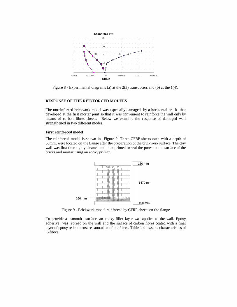
In Figure 8 however, where the strain measures at the inductive vertical transducers 1(4) and 2(3) are described, it is easy to verify that over the V=25 kN the tensile strain is not recorded in that the wall is subjected to a rigid rotation.
10
20
30
40
-0.001 -0.0005 0 0.0005 0.001 0.0015
Strain
Shear load (kN)
(a)(b)
Figure 8 - Experimental diagrams (a) at the 2(3) transducers and (b) at the 1(4).
RESPONSE OF THE REINFORCED MODELS
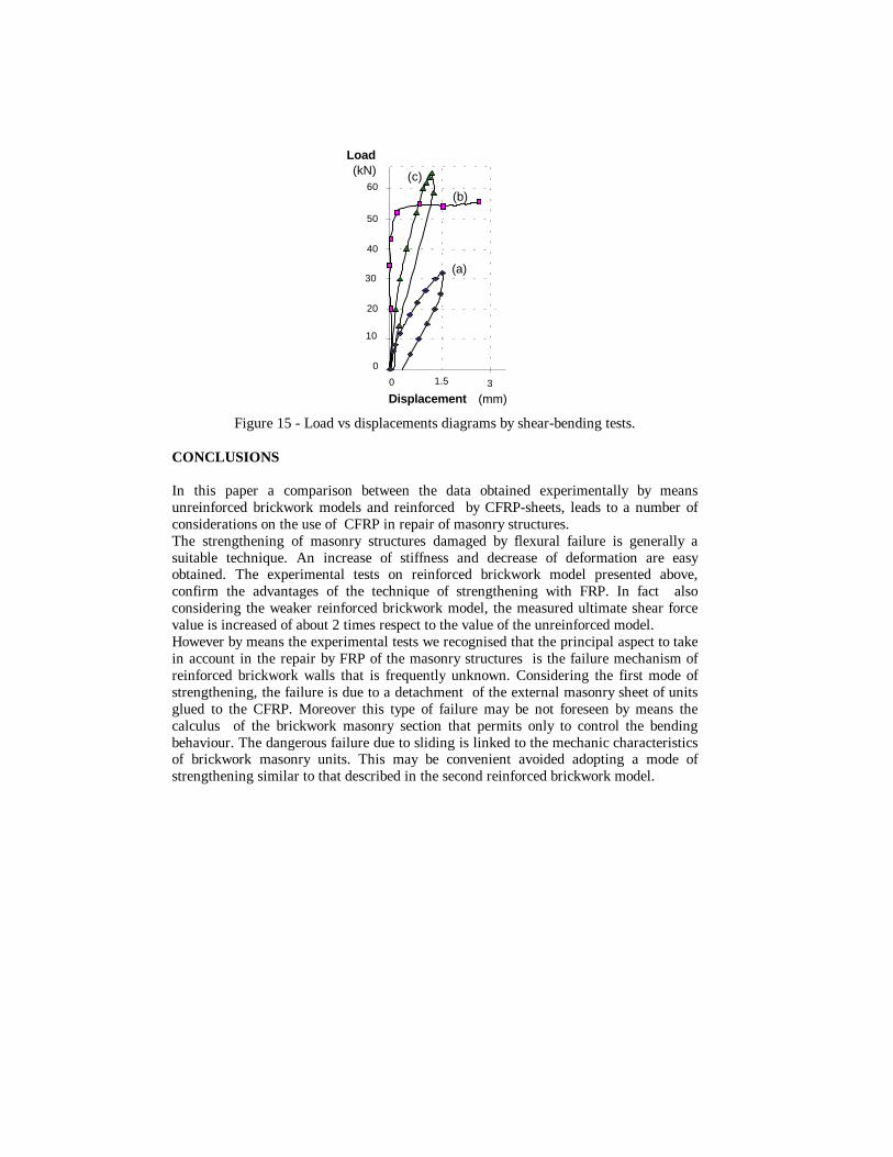
The unreinforced brickwork model was especially damaged by a horizontal crack that developed at the first mortar joint so that it was convenient to reinforce the wall only by means of carbon fibres sheets. Below we examine the response of damaged wall strengthened in two different modes. First reinforced model The reinforced model is shown in Figure 9. Three CFRP-sheets each with a depth of 50mm, were located on the flange after the preparation of the brickwork surface. The clay wall was first thoroughly cleaned and then primed to seal the pores on the surface of the bricks and mortar using an epoxy primer.
1470 mm
150 mm
150 mm
160 mm
5050 50
Figure 9 - Brickwork model reinforced by CFRP-sheets on the flange
To provide a smooth surface, an epoxy filler layer was applied to the wall. Epoxy adhesive was spread on the wall and the surface of carbon fibres coated with a final layer of epoxy resin to ensure saturation of the fibres. Table 1 shows the characteristics of C-fibres.

Table 1 – Characteristics of carbon fibre.
Name MBrace fibre C1-30 Type of fibre High resistance carbon Density 1820 kg/m3 Resistant area by unit of width 1.65 mm2/cm Resistance to tension 3430 N/mm2 Modulus to tension 230000 N/ mm2 Ultimate strain εfu 1.5 % Coefficient of thermal dilation -10-7 K-1
Figure 10 shows an appraisal method to calculate the ultimate internal moment Mu of the masonry wall reinforced by CFRP. The resistant section is given by the carbon fibre area Af=1.65⋅15=24.75mm² and compressive area of masonry. We assume the following values of the ultimate state of masonry: εu=0.15 % and fd=7N/mm2 , to determine the internal resistant moment. The following equations of equilibrium and compatibility may be written:
ffd A
2
bxfσ=
⋅⋅ (12)
xtlxfu
−+ε=
ε (13)
with t=118 mm; (l + t)=1.588m. The value of ultimate bending moment is: MR = Af ⋅ σf ⋅ z ≅ 110kNm (14) The value of shear force, considering the entire area of web section resistant to shear, is: Vu =(fvk0 + 0.4· σV )· (l + t) · t = 73.1kN (15)
tl+t
x
fd
εu
εf
Figure 10 - Resistant section area of the strengthened model by CFRP.
Figure 11 shows the experimental diagrams measured during the shear-bending test. The displacements were measured both by the diagonal transducers and horizontal E, G transducers. It is evident that the response is quite similar. In fact the behaviour is quasi elastic without cracking. This aspect confirms the convenience of strengthening by

CFRP-sheets. A decrease of displacements under loading and a relevant increase of the stiffness of model are obtained.
10
20
30
40
50
0 2 4
Shear load (kN)
Displacement (mm)
(a)
(b)
Figure 11 - Shear load vs displacements in the case of the first strengthened model
Figure 12 shows the diagrams shear load - strain both on the brickwork masonry and on the CFRP-sheets. The experimental test also evidences that the ultimate value of shear force is minor than theoretical Vu since the disposition of the sheets only on the external surface of flange is not totally adequate. During the loading phase, a sudden local failure on the units appeared (Figure 13) due to the sliding of the external masonry sheet of the hollow units glued to the CFRP. The collapse of the model was consequently due to propagation of cracking through the units and the model collapsed at a value of shear force V minor than the theoretical value Vu.
20
40
60
-0.0004 -0.0002 0 0.0002 0.0004 0.0006 0.0008 0.001 0.0012
Strain
Shear load (kN)
(a)(b) (c)
Figure 12 - Shear load vs strain on the tensile masonry (a) by 2and 3 transducers compressive masonry (b) by 1and 4 transducers and on CFRP (c) by strain-gauges.

Figure 13 – View of local failure of the strengthened model
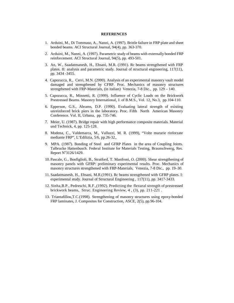
Second reinforced model In the second reinforced model the CFRP-sheets are arranged as shown in Figure 14. In this case the CFRP-sheets are also arranged on the short sides of flange and partially on the web to avoid the weakness to slide of the external sheet of the hollow units. The shear force was increased and the failure load was equal to about 65.2kN(Figure 15). The ultimate mechanism of the second reinforced model was completely different with respect to the unreinforced and the first reinforced model since the two mechanisms of failure described above of cracking by bending and sliding of masonry sheets were avoided. The shear mechanism appeared in this case by ruining the flange and web in the part of model that had not been strengthened by CFRP-sheets. Figure 15 gives a comparison between the shear load vs displacements diagrams obtained on the three brickwork models. Diagram (a) refers the case of the unreinforced model, and (b) (c), to the cases of the reinforced models. The second mode of strengthening seems to be the most convenient method of arranging the CFRP-sheets since this avoids a dangerous brittle mechanism of failure due to the detachment of external masonry sheet of the hollow units.
1470mm
150mm
800mm
150mm
120 210
1470mm
200
480mm
2300mm
530
160
50 50 50
1320mm
Figure 14 - Brickwork reinforced model
0
10
20
30
40
50
60
0 31.5
Load (kN)
Displacement (mm)
(a)
(b)
(c)
Figure 15 - Load vs displacements diagrams by shear-bending tests.
CONCLUSIONS
In this paper a comparison between the data obtained experimentally by means unreinforced brickwork models and reinforced by CFRP-sheets, leads to a number of considerations on the use of CFRP in repair of masonry structures. The strengthening of masonry structures damaged by flexural failure is generally a suitable technique. An increase of stiffness and decrease of deformation are easy obtained. The experimental tests on reinforced brickwork model presented above, confirm the advantages of the technique of strengthening with FRP. In fact also considering the weaker reinforced brickwork model, the measured ultimate shear force value is increased of about 2 times respect to the value of the unreinforced model. However by means the experimental tests we recognised that the principal aspect to take in account in the repair by FRP of the masonry structures is the failure mechanism of reinforced brickwork walls that is frequently unknown. Considering the first mode of strengthening, the failure is due to a detachment of the external masonry sheet of units glued to the CFRP. Moreover this type of failure may be not foreseen by means the calculus of the brickwork masonry section that permits only to control the bending behaviour. The dangerous failure due to sliding is linked to the mechanic characteristics of brickwork masonry units. This may be convenient avoided adopting a mode of strengthening similar to that described in the second reinforced brickwork model.
REFERENCES 1. Arduini, M., Di Tommaso, A., Nanni, A. (1997). Brittle failure in FRP plate and sheet
bonded beams. ACI Structural Journal, 94(4), pp. 363-370. 2. Arduini, M., Nanni, A. (1997). Parametric study of beams with externally bonded FRP
reinforcement. ACI Structural Journal, 94(5), pp. 493-501. 3. An, W., Saadatmanesh, H., Ehsani, M.R. (1991). Rc beams strengthened with FRP
plates. II: analysis and parametric study. Journal of structural engineering, 117(11), pp. 3434 -3455.
4. Capozucca, R., Cerri, M.N. (2000). Analysis of an experimental masonry vault model
damaged and strengthened by CFRP. Proc. Mechanics of masonry structures strengthened with FRP-Materials, (in italian) Venezia, 7-8 Dic., pp. 129 – 140.
5. Capozucca, R., Minnetti, R. (1999). Influence of Cyclic Loads on the Brickwork
Prestressed Beams. Masonry International, J. of B.M.S., Vol. 12, No.3, pp.104-110. 6. Epperson, G.S., Abrams, D.P. (1990). Evaluating lateral strength of existing
unreinforced brick piers in the laboratory. Proc. Fifth North American Masonry Conference. Vol. II, Urbana, pp. 735-746.
7. Meier, U. (1987). Bridge repair with high performance composite materials. Material
und Technick, 4, pp. 125-128. 8. Modena, C., Valdemarca, M., Valluzzi, M. R. (1999), “Volte murarie rinforzate
mediante FRP”, L’Edilizia, 5/6, pp.26-32,. 9. MPA. (1987). Bonding of Steel and GFRP Plates in the area of Coupling Joints.
Talbrucke Hattenbusch. Federal Institute for Materials Testing, Braunschwerg, Res. Report No3126/1429.
10. Pascale, G., Bonfiglioli, B., Stratford, T. Manfroni, O. (2000). Shear strengthening of
masonry panels with GFRP: preliminary experimental results. Proc. Mechanics of masonry structures strengthened with FRP-Materials, Venezia, 7-8 Dic., pp. 19–30.
11. Saadatmanesh, H., Ehsani, M.R.(1991). Rc beams strengthened with GFRP plates. I:
experimental study. Journal of Structural Engineering , 117(11), pp. 3417-3433. 12. Sinha,B.P., Pedreschi, R.F.,(1992). Predicting the flexural strength of prestressed
brickwork beams, Struc. Engineering Review, 4 , (3), pp. 211-221 . 13. Triantafillou,T.C.(1998). Strengthening of masonry structures using epoxy-bonded
FRP laminates, J. Composites for Construction, ASCE, 2(5), pp.96-104.