Brian Genduso Structural Option Faculty Consultant – Dr ...
19
Brian Genduso Structural Option Faculty Consultant – Dr. Linda Hanagan University of Cincinnati Athletic Center Cincinnati, Ohio Courtesy of Bernard Tschumi Architects Structural Concepts/Structural Existing Conditions Report October 8, 2003 Executive Summary This report investigates the structural concepts used to design the University of Cincinnati Athletic Center in Cincinnati, Ohio. It is broken down into four sections: Building Description The UC Athletic Center is an 8 story, 220,000 ft 2 multi-use sports facility. It has a unique curved shape and “diagrid” exterior. The floor and roof systems are composite steel wide flange beams with composite slab-on-deck. Typical bays are about 27’x27’, thought the layout is highly varied by floor. Interior columns are full height. Exterior “V” columns support the rigid diagrid enclosure, transferring load into spread footings and piers below grade. Lateral bracing is composed of the diagrid structure, braced frames, and foundation shear walls. Design Codes and Standards The 1998 Ohio Basic Building Code is the model code. Loading is determined with ASCE 7-98. Calculations Gravity (structure self weight, superimposed dead and live) and Lateral (wind and seismic) loads were derived and summed. Total dead weight per above- grade floor varied from 2300-2800 kips. Critical unfactored wind base shear (408.3k) is greater than unfactored seismic base shear (392.0k). Spot checking will be done for one floor framing element and one lateral frame. These calculations have not been performed yet. Additional Considerations Page 1 of 8
Transcript of Brian Genduso Structural Option Faculty Consultant – Dr ...

Brian Genduso Structural Option Faculty Consultant – Dr. Linda Hanagan University of Cincinnati Athletic Center Cincinnati, Ohio
Courtesy of Bernard Tschumi Architects Structural Concepts/Structural Existing Conditions Report
October 8, 2003 Executive Summary
This report investigates the structural concepts used to design the University of Cincinnati Athletic Center in Cincinnati, Ohio. It is broken down into four sections:
Building Description The UC Athletic Center is an 8 story, 220,000 ft2 multi-use sports facility. It has a unique curved shape and “diagrid” exterior. The floor and roof systems are composite steel wide flange beams with composite slab-on-deck. Typical bays are about 27’x27’, thought the layout is highly varied by floor. Interior columns are full height. Exterior “V” columns support the rigid diagrid enclosure, transferring load into spread footings and piers below grade. Lateral bracing is composed of the diagrid structure, braced frames, and foundation shear walls.
Design Codes and Standards The 1998 Ohio Basic Building Code is the model code. Loading is
determined with ASCE 7-98. Calculations
Gravity (structure self weight, superimposed dead and live) and Lateral (wind and seismic) loads were derived and summed. Total dead weight per above-grade floor varied from 2300-2800 kips. Critical unfactored wind base shear (408.3k) is greater than unfactored seismic base shear (392.0k).
Spot checking will be done for one floor framing element and one lateral frame. These calculations have not been performed yet.
Additional Considerations
Page 1 of 8

Building Description
Introduction The University of Cincinnati Athletic Center is an 8 story, 220,000 ft2 multi-use facility to be located in the heart of UC’s “Varsity Village” athletic complex. The building is designed to accommodate various sports-related activities all under one roof and to function as the social link and architectural centerpiece of a multi-stage athletic expansion plan. As such, it will be situated between two main sports facilities, the Nippert Football Stadium and the Shoemaker Center, with easy access to other sports fields and areas. See figure in Appendix A.1. The structure is made up of 3 below-grade stories (levels 100-300) and 5 above-grade stories (levels 400-800). The structure will accommodate office space, public meeting areas, computer labs, locker rooms, treatment areas, and other related athletic support.
Architecture Architecturally, the design is characterized by its unique exterior façade (right). The façade consists of a triangulated “exo-skeleton” of concrete-covered steel. This skeleton, referred to as a “diagrid”, forms a visually dominant shell around the building. The heaviness of this exterior system is offset by its light color and appears to be lifted off the ground by a series of v-shaped columns. Also unique to the building is its curved shape. There are no corners in above-grade plan, creating a rather unusual kidney or “link-pin” shape (right). The interior space of the building itself is divided by a 5-story atrium running down the middle of its main section. To each side are offices, meeting rooms, and administrative areas. Below ground is a more conventional rectangular footprint, with mainly sports facilities and locker rooms. Horizontal movement through the building is kept simple by its compact design, however vertical movement is facilitated by a set of elevators and a grand staircase in the atrium.
Page 2 of 8

Structural System Floor system
The floor framing is typical steel composite beams with composite metal decking supporting one-way slab diaphragms. Most connections are shear only, however, some elements framing into full height columns near the atrium are designed with moment connections to support atrium walkways. The layout is not regular due to the highly curved shape of the building, however, the N-S direction spacing is typically 9’ o.c. In general, three main framing areas can be identified on the above-grade floors as shown in the figure below. These are: Orange – North bays (longer, more regular spans) Green – Elevator and stair cores (highly varied, shorter spans) Pink – Atrium bays (regular spacing with moment connections)
The closest approximation to a typical bay occurs in the rectangular basement at levels 200 and 300. A bay there measures 27’ x 27’-8” with intermediate beams spaced at 9’ o.c. The beams are partially composite, with a 6.5 inch slab-on-deck. Deck depth is 2 inches. A diagram representing this typical bay is shown at right.
Page 3 of 8

Roof The roof is also a composite steel beam system with composite slab. The roof consists of a lower roof and high roof. The high roof covers the atrium and the east portion of the building. The layout is consistent with the 27’ bays found on lower levels. Slab thickness on the roof is 6 inches with a 2 inch deck.
Columns Within the building there are two main rows of steel columns. These rows straddle the atrium in the N-S direction and support the interior gravity loads from the floors and partitions. All interior columns are the full height of the building. On the upper exterior floors (levels 500-800), the diagrid carries the vertical loads, and therefore there are no typical columns. At levels 400 and 300, however, the diagrid is supported by large “V” columns. These are either heavy wide flange rolled shapes or built-up boxes. They are rigidly connected to both the diagrid and the substructure. Gravity loads from the upper floors is transferred down through the V columns into single below-grade columns. A rendering of a V column is shown right.
Foundation
The foundation utilizes a combination of spread footings and drilled piers, set into sound gray shale. Shear walls are typically 1’6” thick. Part of the foundation will be built over portions of existing facilities. These facilities have been demolished and the nearby Shoemaker Center is underpinned during excavation to ensure structural integrity. A portion of the building along the North side interfaces with the Shoemaker Center. Enclosure As explained above, the enclosure consists primarily of a diagrid structure. The diagrid acts as a rigid shell, and for structural purposes can be considered a very thin, deep beam. The diagrid itself is composed of wide flange rolled sections welded or bolted for full restraint. The steel will be covered with concrete or similar material to produce a monolithic appearance. Between the beams are triangular window glazings. A rendering of the diagrid connection is shown right.
Lateral bracing Wind and seismic loading is transferred to the ground through an unusual lateral system. Loads are accumulated above grade at the diagrid façade. Since the façade acts as a rigid structure, it transfers all loads to a braced frame system at the diagrid base (level 500). The braced frame acts in tandem with the moment-connected V columns to transfer the shear into the foundation shearwalls and
Page 4 of 8

substructure columns. Two braced frames for the critical E-W loading are located approximately centrically on either end of the building. These braced frames will be discussed in more detail in a later section.
Material Strengths Material strengths were obtained from drawing general notes. Reinforced Concrete
Location Aggregate f'c (psi) Footings, piers Normal weight 3000 Slab on grade Normal weight 3000 Walls and columns Normal weight 4000 Beams and slabs Normal weight 4000 Slab on steel deck Normal weight 3000 Equipment pads/curbs Normal weight 3000 Lean concrete Lightweight 3000
Reinforcement Type ASTM Standard fy (ksi) Deformed reinforcing bars A615 Gr. 60 60 Welded wire fabric A185 Gr. 70 70
Structural Steel Shape ASTM Standard fy (ksi) Wide flanges A992 50 Channels and tees A572 Grade 50 50 Rectangular & round HSS A500 Grade B 46 Pipes A53 Type E 35 Angles A36 36 Plates A36 36 Built-up sections (box & I) A572 Grade 50 50
Design Codes and Standards Building Codes 1998 Ohio Basic Building Code 2002 Ohio Building Code (Seismic Design Only) Design Specifications and Standards
Loads ASCE 7-98 “Minimum Design Loads for Buildings and Other Structures”
Concrete
ACI 301 “Specifications for Structural Concrete for Buildings” ACI 315 “Manual of Standard Practice for Detailing Reinforced Concrete Structures” ACI 318 “Building Code Requirements for Reinforced Concrete and Commentary”
Structural Steel
AISC “Manual of Steel Construction, Load and Resistance Factor Design”, 3rd Edition AISC “Code of Standard Practice for Steel Buildings and Bridges”
Page 5 of 8

AWS D1.1 “Structural Welding Code” AISC “Specification for Structural Joints Using ASTM A325 or A490 Bolts” AISI “Specification for the Design of Cold-Formed Steel Structural Members” AISC/CISC – Steel Design Guide Series 11: Floor Vibrations Due to Human Activity
Calculations
Loads Building loads were obtained using ASCE 7-98 Standard, which is referenced in the 1998 Ohio Basic Building Code. The loading can be split into two main categories, gravity loads and lateral loads. Most of this section is referenced in appendices for convenience and ease of reading, due to its computation-intensive nature. Gravity
Gravity loads consist of the superstructure dead load, the superimposed dead load, and live loading.
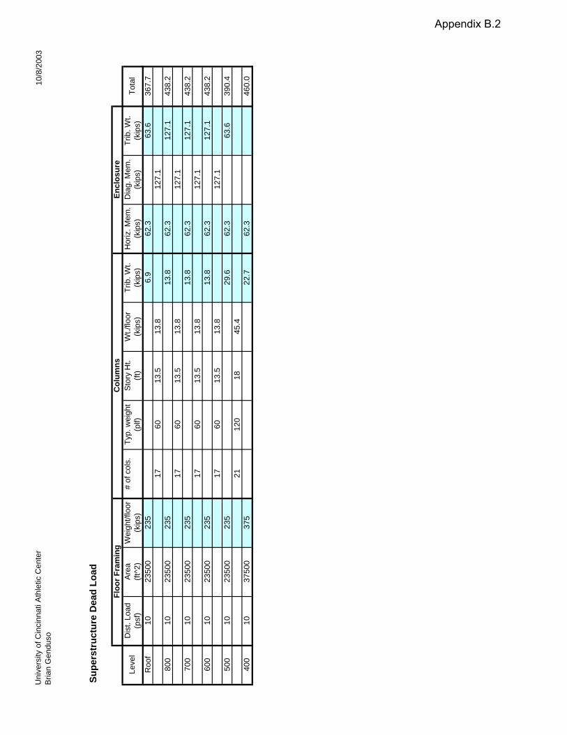
Superstructure load – The structural engineer used a computer analysis program to determine the self weight of the superstructure. Since this is a preliminary report, these loads were estimated using a simplified procedure. The theory behind the procedure is found in Appendix B.1, while the load calculations are tabulated in Appendix B.2.
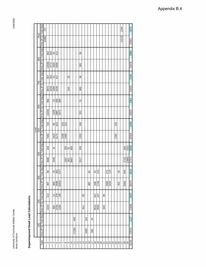
Superimposed load – Loading diagrams on the drawings were used to
compile total superimposed loads for each floor. Appendix B.3 shows the dead load for each type of occupancy in the “Total Dead” column. Appendix B.4 tabulates the total load for each floor. These calculations will be used in a later section. Dead Loads are summarized below.
Superimposed Superstructure Total Level
(kip) (kip) (kips) Roof 1973 368 2341 800 2084 438 2522 700 2100 438 2538 600 2361 438 2800 500 2209 390 2600
400 (ground) 5026 460 5486
Live load – Loading diagrams on the drawings were used to compile live loads for each floor. Appendix B.3 shows the live load for each type of occupancy in the “Live Load” column. Snow loads were assumed to be 30psf with 50psf drifts as indicated on the drawings.
Page 6 of 8

LateralLateral loads were evaluated for wind and seismic loading.
Wind – Wind loads were based on a 90mph basic wind speed, exposure B, and an importance factor of 1.15. Though the shape of the building is unusual, the structural engineer made the assumption that the building could be modeled as a simple rectangular box, 5 stories high. The high roof was not taken into consideration for purposes of simplicity. The preliminary calculations are found in Appendix C.1. Wind pressures gradients were evaluated in both the N-S and E-W directions, as found in Appendix C.2. The summation of story shear is evaluated in Appendix C.3. They are summarized in graphical format below.
Wind shear in N-S direction
Wind shear in E-W direction
Seismic - The governing code used in the structural design of the UCAC is the 2002 OBBC, which is adapted from the IBC 2000. IBC 2000 references ASCE 7, and therefore seismic analysis was performed using ASCE 7-98 for consistency with the wind analysis. The design is based on Seismic Use Group II, Site Class B, and an importance factor of 1.25. Using these provisions, the building fell under Seismic Design Category A, and therefore the story shear could be calculated as Fx=0.01*g. Preliminary calculations to determine the SDC are found in Appendix C.4. Seismic story shear is summarized in the figure below, with the total base shear equal to 392 kips.
Page 7 of 8

Seismic shear in both directions.
Spot Checking Spot checking for one floor framing element and one lateral frame was done using the loads calculated in the Loads section. Floor framing element
Not yet completed
Lateral frameNot yet completed
Additional Considerations
Not yet completed
Notes:
Full calculations and design materials are available upon request. All images courtesy of Bernard Tschumi Architects or Arup Services.
Page 8 of 8

U N IV E R S IT Y of CIN CIN N A T I A T HLE T IC CE N T E R and V A R S IT Y V ILLA G EBERNARD TSCHUMI ARCHITECTS • GLASERWORKS
A T H L E T ICC E N T E R
V A R S IT Y P L
C O R R Y B O U L E V A R D
S C H M ID L A P PP L A Z A
N IP P E R T S TA D IU M
S H O E M A K E RC E N T E R
B A S E B A L L S TA D IU MF O OT B A L L F IE L D
T R A C K A N D F IE L DS O C C E R F IE L D
T E N N IS C O U R T S
PA R K IN G E N T R A N C E
Appendix A.1

Appendix B.1

Appendix B.1
Uni
vers
ity o
f Cin
cinn
ati A
thle
tic C
ente
rB
rian
Gen
duso
10/8
/200
3
Supe
rstr
uctu
re D
ead
Load
Floo
r Fra
min
gC
olum
nsEn
clos
ure
Leve
lD
ist.
Load
Are
aW
eigh
t/flo
or#
of c
ols.
Typ.
wei
ght
Sto
ry H
t.W
t./flo
orTr
ib. W
t.H
oriz
. Mem
.D
iag.
Mem
.Tr
ib. W
t.To
tal
(psf
)(ft
^2)
(kip
s)(p
lf)(ft
)(k
ips)
(kip
s)(k
ips)
(kip
s)(k
ips)
Roo
f10
2350
023
56.
962
.363
.636
7.7
1760
13.5
13.8
127.
180
010
2350
023
513
.862
.312
7.1
438.
217
6013
.513
.812
7.1
700
1023
500
235
13.8
62.3
127.
143
8.2
1760
13.5
13.8
127.
160
010
2350
023
513
.862
.312
7.1
438.
217
6013
.513
.812
7.1
500
1023
500
235
29.6
62.3
63.6
390.
421
120
1845
.440
010
3750
037
522
.762
.346
0.0
Appendix B.2

Uni
vers
ity o
f Cin
cinn
ati A
thle
tic C
ente
rB
rian
Gen
duso
10/8
/200
3
Supe
rimpo
sed
Load
Typ
es
Are
a O
ccup
ancy
Floo
r Fin
ish
Floo
r Sla
bC
eilin
g/S
ervi
ces
Par
titio
nsA
dditi
onal
Tota
l Dea
dLi
ve L
oad
Tota
l Unf
acto
red
(psf
)(p
sf)
(psf
)(p
sf)
(psf
)(p
sf)
(psf
)(p
sf)
1H
igh
Roo
f60
1070
3010
02
Offi
ce66
1020
9650
146
3M
ulti-
purp
ose
club
6610
7610
017
64
Sta
ir30
3010
013
05
Atri
um/C
orrid
or25
6610
101
100
201
6M
echa
nica
l roo
m66
1050
126
125
251
7C
ompu
ter l
ab25
6610
101
100
201
8Fi
xed
seat
ing
110
1010
130
6019
09
Sta
ge25
6610
101
100
201
10Lo
bby/
Gen
eral
ass
embl
y25
6610
101
100
201
11Lo
cker
room
2510
2055
100
155
12W
ork
area
2565
1020
120
100
220
13S
how
ers/
Res
t roo
m25
6610
101
6016
114
Sto
rage
2566
1010
112
522
615
Laun
dry
2510
3515
018
516
Ram
p25
6691
100
191
17E
leva
tor m
achi
ne ro
om66
6625
031
618
Mee
ting
room
6610
7660
136
19Tr
eatm
ent a
rea
2566
1020
121
100
221
20V
ideo
room
2566
1020
121
100
221
21H
ydro
ther
apy
2566
1010
140
050
122
Load
ing
dock
3066
1010
610
020
623
Am
bula
nce
park
ing
3079
1011
910
021
924
Wal
kway
roof
135
1830
4825
Thea
ter c
ontro
l roo
m25
6610
2012
110
022
126
Tras
h co
mpa
ctor
6610
7635
042
627
Roo
f25
6010
9560
155
28E
xter
ior t
ruck
load
ing
9079
1017
910
027
929
Ext
erio
r non
-truc
k lo
adin
g90
6610
166
100
266
Appendix B.3
Uni
vers
ity o
f Cin
cinn
ati A
thle
tic C
ente
rB
rian
Gen
duso
10/8
/200
3
Supe
rimpo
sed
Dea
d Lo
ad C
alcu
latio
ns
Leve
l10
020
030
040
050
060
070
080
0R
oof
Type
Are
a (ft
^2)
Tota
l (ki
p)A
rea
(ft^2
)To
tal (
kip)
Are
a (ft
^2)
Tota
l (ki
p)A
rea
(ft^2
)To
tal (
kip)
Are
a (ft
^2)
Tota
l (ki
p)A
rea
(ft^2
)To
tal (
kip)
Are
a (ft
^2)
Tota
l (ki
p)A
rea
(ft^2
)To
tal (
kip)
Are
a (ft
^2)
Tota
l (ki
p)1
1038
272
72
2224
214
997
9635
8634
475
8372
810
249
984
9973
957
1003
896
43
4234
322
4772
363
448
314
669
2010
4631
1615
4814
2843
1694
5116
5550
537
5037
935
9836
361
7062
358
8759
561
0661
760
5861
26
1558
196
1093
213
7754
7268
97
2228
225
823
0730
024
8532
39
803
8154
455
1089
0790
011
1725
994
912 13
2017
204
1053
106
501
5196
998
955
9614
641
6515
4393
154
1688
781
1735
824
1885
1064
754
842
1935
2942
717
4921
220 21
943
9522
2556
271
2310
3312
324 25
1282
155
2645
134
2713
119
1246
2850
5090
447
2384
529
1398
223
21S
ums
2201
011
2721
638
2037
2847
035
2337
371
5026
2241
622
0923
537
2361
2352
021
0023
478
2084
2350
119
73
Appendix B.4

Appendix C.1

Appendix C.1

University of Cincinnati Athletic CenterBrian Genduso
10/8/2003
N-S Direction
CoefficientsWindward 16.3Leeward -3.7
Height Kz Windward Leeward Total MWFRS(ft) (psf) (psf) (psf)
0-15 0.57 9.3 -3.7 13.015-20 0.62 10.1 -3.7 13.820-25 0.66 10.8 -3.7 14.525-30 0.70 11.4 -3.7 15.130-40 0.76 12.4 -3.7 16.140-50 0.81 13.2 -3.7 16.950-60 0.85 13.9 -3.7 17.660-70 0.89 14.5 -3.7 18.270-80 0.93 15.2 -3.7 18.9
E-W Direction
CoefficientsWindward 16.3Leeward -9.1
Height Kz Windward Leeward Total MWFRS(ft) (psf) (psf) (psf)
0-15 0.57 9.3 -9.1 18.415-20 0.62 10.1 -9.1 19.220-25 0.66 10.8 -9.1 19.925-30 0.70 11.4 -9.1 20.530-40 0.76 12.4 -9.1 21.540-50 0.81 13.2 -9.1 22.350-60 0.85 13.9 -9.1 23.060-70 0.89 14.5 -9.1 23.670-80 0.93 15.2 -9.1 24.3
Appendix C.2

Uni
vers
ity o
f Cin
cinn
ati A
thle
tic C
ente
rB
rian
Gen
duso
10/8
/200
3
N-S
Dire
ctio
n
Bui
ldin
g he
ight
(ft)
72B
uild
ing
trib
wid
th (f
t)12
0
Leve
lS
tory
ht.
Trib
ht.
Tota
l ht.
P 1
H 1
P 2
H 2
P 3
H 3
Sto
ry D
ist.
Load
Cum
. Dis
t. Lo
adS
tory
She
arC
um. S
hear
(ft)
(ft)
(ft)
(psf
)(ft
)(p
sf)
(ft)
(psf
)(ft
)(p
lf)(p
lf)(k
ips)
(kip
s)R
oof
6.75
18.2
4.75
18.9
212
412
414
.914
.913
.565
.25
800
13.5
17.6
8.25
18.2
5.25
241
365
28.9
43.8
13.5
51.7
570
013
.516
.11.
7516
.910
17.6
1.75
228
593
27.4
71.2
13.5
38.2
560
013
.514
.50.
2515
.15
16.1
8.25
212
805
25.4
96.6
13.5
24.7
550
015
.75
136
13.8
514
.54.
7521
610
2125
.912
2.5
189
400
(gro
und)
913
9N
/ AN
/AN
/A12
2.5
E-W
Dire
ctio
n
Bui
ldin
g he
ight
(ft)
72B
uild
ing
trib
wid
th (f
t)30
0
Leve
lS
tory
ht.
Trib
ht.
Tota
l ht.
P 1
H 1
P 2
H 2
P 3
H 3
Sto
ry D
ist.
Load
Cum
. Dis
t. Lo
adS
tory
She
arC
um. S
hear
(ft)
(ft)
(ft)
(psf
)(ft
)(p
sf)
(ft)
(psf
)(ft
)(p
lf)(p
lf)(k
ips)
(kip
s)R
oof
6.75
23.6
4.75
24.3
216
116
148
.248
.213
.565
.25
800
13.5
238.
2523
.65.
2531
447
494
.114
2.3
13.5
51.7
570
013
.521
.51.
7522
.310
231.
7530
177
590
.323
2.6
13.5
38.2
560
013
.519
.90.
2520
.55
21.5
8.25
285
1060
85.5
318.
013
.524
.75
500
15.7
518
.46
19.2
519
.94.
7530
113
6190
.340
8.3
189
400
(gro
und)
918
.49
N/ A
N/A
N/A
408.
3
Appendix C.3

Appendix C.4