Smartphone-based User Location Tracking in Indoor Environment
BreathTrack: Tracking Indoor Human Breath Status via ...
13
IEEE INTERNET OF THINGS JOURNAL, VOL. 6, NO. 2, APRIL 2019 3899 BreathTrack: Tracking Indoor Human Breath Status via Commodity WiFi Dongheng Zhang , Yang Hu , Yan Chen , Senior Member, IEEE, and Bing Zeng , Fellow, IEEE Abstract—In this paper, we propose a contact-free breath tracking system, BreathTrack, to track the status of breath using the off-the-shelf WiFi devices. BreathTrack exploits the phase variation of the channel state information (CSI) to track human breath. To resolve the phase distortions introduced by the hard- ware imperfection of the commodity WiFi chips, BreathTrack utilizes both the hardware and software correction methods. The time-invariant PLL phase offset is calibrated by the hard- ware correction using cables and splitters, while the time-varying carrier frequency offset, sampling frequency offset and packet detection delay are removed by the software corrections using the phase difference between the CSI at the receiver antennas and that at the reference antenna connected from the transmit- ter. Moreover, BreathTrack utilizes the sparse recovery method to find the dominant path in the multipath indoor environment and derive the corresponding complex attenuation coefficient. Then, the phase variation of the complex attenuation coefficient is uti- lized to extract the detailed breath status and the breath rate. Extensive experiments are conducted to show that BreathTrack could estimate the breath rate with the median accuracy of over 99% in most scenarios, and could track the detailed status of breath directly using the raw phase variation. Index Terms—Breath tracking, commodity WiFi, phase distor- tion, sparse recovery, vital sign. I. I NTRODUCTION B REATH rate is an important vital sign for health moni- toring and medical diagnosis. While we have witnessed, in the past few years with the development of Internet of Things, the increasing research interests and progresses in ubiquitous health monitoring [1]–[4], traditional methods are intrusive that require the physical contact between human and sensors [5], [6], which affects the normal breath of human and cannot be applied to the long-term breath monitoring. To resolve this challenge, radio frequency-based monitor- ing schemes that can provide nonintrusive human sensing have been proposed [7]–[25], e.g., the vital-radio uses the frequency modulated continuous wave signal to estimate the breath and Manuscript received November 17, 2018; revised December 20, 2018; accepted January 11, 2019. Date of publication January 15, 2019; date of current version May 8, 2019. This work was supported in part by the National Natural Science Foundation of China under Grant 61672137 and Grant 61602090 and in part by the 111 Project No. B17008. The work of Yan Chen was supported in part by the Thousand Youth Talents Program of China. (Corresponding author: Yan Chen.) The authors are with the Center for Intelligent Networking and Communications, School of Information and Communication Engineering, University of Electronic Science and Technology of China, Chengdu 611731, China (e-mail: [email protected]; [email protected]; [email protected]; [email protected]). Digital Object Identifier 10.1109/JIOT.2019.2893330 heart rate [7]. However, such a system is not only expensive, but also occupies a large wireless band, which limits its appli- cation. To reduce the cost, the WiFi-based methods have been proposed [8]–[12], [18]. In [8], the UbiBreathe system has been proposed to utilize the received signal strength (RSS) to monitor the breath signal. Since the RSS is not very sensi- tive to the minor displacements in the environment, it requires users to hold the WiFi devices close to their chests to achieve reasonable performance. The amplitude of channel state infor- mation (CSI) has also been utilized to estimate the breath rate [9]. However, similar to the RSS, the amplitude of CSI is also not very sensitive to the minor displacement in the envi- ronment, due to which the estimation performance is limited. To achieve reasonable performance, sophisticated subcarrier selection, denoising, and filtering procedures are needed. Since the frequency of breath varies in a very narrow band, i.e., about 0.2 Hz, it is difficult to determine whether the estimated frequency is corresponding to the breath frequency. Compared with the RSS and the amplitude of CSI, the phase of CSI is much more sensitive to the minor displacement in the environment, i.e., the phase of CSI is more suitable for breath rate estimation. However, the hardware imperfec- tion of the commodity WiFi chips will introduce different kinds of phase distortions, which makes it difficult to obtain accurate CSI phase information. It has been found that the phases of the measured CSIs across packets are not correlated even in very short time intervals [26]. Therefore, it is very difficult to estimate the breath rate directly from the phase variation of the measured CSI. To solve the phase distortion problem, the PhaseBeat system was proposed in [10], which utilizes the phase difference between receiver antennas to elim- inate the phase distortion. However, since the CSI measured on the antennas is affected by the minor displacement caused by breath, the phase difference between antennas is actually the subtraction of two periodic signals, which makes the model in [10] inaccurate. Another challenge for the breath tracking in the indoor environment is the multipath effect. In a multipath indoor environment, the received signal is not periodic due to the aggregation of the multipath effect, and thus the breath rate cannot be directly obtained from the frequency components of the CSI. Moreover, the breath may be interrupted due to vari- ous factors such as talking, thinking, or even some unconscious behaviors. In such a case, only the estimation of the breath rate may not be enough. Instead, it would be more significant if we could track the detailed breath status, i.e., the time domain breath waveform similar to the electrocardiography signals. 2327-4662 c 2019 IEEE. Personal use is permitted, but republication/redistribution requires IEEE permission. See http://www.ieee.org/publications_standards/publications/rights/index.html for more information.
Transcript of BreathTrack: Tracking Indoor Human Breath Status via ...

IEEE INTERNET OF THINGS JOURNAL, VOL. 6, NO. 2, APRIL 2019 3899
BreathTrack: Tracking Indoor Human BreathStatus via Commodity WiFi
Dongheng Zhang , Yang Hu , Yan Chen , Senior Member, IEEE, and Bing Zeng , Fellow, IEEE
Abstract—In this paper, we propose a contact-free breathtracking system, BreathTrack, to track the status of breath usingthe off-the-shelf WiFi devices. BreathTrack exploits the phasevariation of the channel state information (CSI) to track humanbreath. To resolve the phase distortions introduced by the hard-ware imperfection of the commodity WiFi chips, BreathTrackutilizes both the hardware and software correction methods.The time-invariant PLL phase offset is calibrated by the hard-ware correction using cables and splitters, while the time-varyingcarrier frequency offset, sampling frequency offset and packetdetection delay are removed by the software corrections usingthe phase difference between the CSI at the receiver antennasand that at the reference antenna connected from the transmit-ter. Moreover, BreathTrack utilizes the sparse recovery method tofind the dominant path in the multipath indoor environment andderive the corresponding complex attenuation coefficient. Then,the phase variation of the complex attenuation coefficient is uti-lized to extract the detailed breath status and the breath rate.Extensive experiments are conducted to show that BreathTrackcould estimate the breath rate with the median accuracy of over99% in most scenarios, and could track the detailed status ofbreath directly using the raw phase variation.
Index Terms—Breath tracking, commodity WiFi, phase distor-tion, sparse recovery, vital sign.
I. INTRODUCTION
BREATH rate is an important vital sign for health moni-toring and medical diagnosis. While we have witnessed,
in the past few years with the development of Internet ofThings, the increasing research interests and progresses inubiquitous health monitoring [1]–[4], traditional methods areintrusive that require the physical contact between human andsensors [5], [6], which affects the normal breath of human andcannot be applied to the long-term breath monitoring.
To resolve this challenge, radio frequency-based monitor-ing schemes that can provide nonintrusive human sensing havebeen proposed [7]–[25], e.g., the vital-radio uses the frequencymodulated continuous wave signal to estimate the breath and
Manuscript received November 17, 2018; revised December 20, 2018;accepted January 11, 2019. Date of publication January 15, 2019; date ofcurrent version May 8, 2019. This work was supported in part by theNational Natural Science Foundation of China under Grant 61672137 andGrant 61602090 and in part by the 111 Project No. B17008. The work ofYan Chen was supported in part by the Thousand Youth Talents Program ofChina. (Corresponding author: Yan Chen.)
The authors are with the Center for Intelligent Networking andCommunications, School of Information and Communication Engineering,University of Electronic Science and Technology of China, Chengdu611731, China (e-mail: [email protected]; [email protected];[email protected]; [email protected]).
Digital Object Identifier 10.1109/JIOT.2019.2893330
heart rate [7]. However, such a system is not only expensive,but also occupies a large wireless band, which limits its appli-cation. To reduce the cost, the WiFi-based methods have beenproposed [8]–[12], [18]. In [8], the UbiBreathe system hasbeen proposed to utilize the received signal strength (RSS) tomonitor the breath signal. Since the RSS is not very sensi-tive to the minor displacements in the environment, it requiresusers to hold the WiFi devices close to their chests to achievereasonable performance. The amplitude of channel state infor-mation (CSI) has also been utilized to estimate the breathrate [9]. However, similar to the RSS, the amplitude of CSI isalso not very sensitive to the minor displacement in the envi-ronment, due to which the estimation performance is limited.To achieve reasonable performance, sophisticated subcarrierselection, denoising, and filtering procedures are needed. Sincethe frequency of breath varies in a very narrow band, i.e.,about 0.2 Hz, it is difficult to determine whether the estimatedfrequency is corresponding to the breath frequency.
Compared with the RSS and the amplitude of CSI, the phaseof CSI is much more sensitive to the minor displacementin the environment, i.e., the phase of CSI is more suitablefor breath rate estimation. However, the hardware imperfec-tion of the commodity WiFi chips will introduce differentkinds of phase distortions, which makes it difficult to obtainaccurate CSI phase information. It has been found that thephases of the measured CSIs across packets are not correlatedeven in very short time intervals [26]. Therefore, it is verydifficult to estimate the breath rate directly from the phasevariation of the measured CSI. To solve the phase distortionproblem, the PhaseBeat system was proposed in [10], whichutilizes the phase difference between receiver antennas to elim-inate the phase distortion. However, since the CSI measuredon the antennas is affected by the minor displacement causedby breath, the phase difference between antennas is actuallythe subtraction of two periodic signals, which makes the modelin [10] inaccurate.
Another challenge for the breath tracking in the indoorenvironment is the multipath effect. In a multipath indoorenvironment, the received signal is not periodic due to theaggregation of the multipath effect, and thus the breath ratecannot be directly obtained from the frequency components ofthe CSI. Moreover, the breath may be interrupted due to vari-ous factors such as talking, thinking, or even some unconsciousbehaviors. In such a case, only the estimation of the breath ratemay not be enough. Instead, it would be more significant ifwe could track the detailed breath status, i.e., the time domainbreath waveform similar to the electrocardiography signals.
2327-4662 c© 2019 IEEE. Personal use is permitted, but republication/redistribution requires IEEE permission.See http://www.ieee.org/publications_standards/publications/rights/index.html for more information.

3900 IEEE INTERNET OF THINGS JOURNAL, VOL. 6, NO. 2, APRIL 2019
Fig. 1. Illustration of the BreathTrack system. The raw CSI is calibrated according to the signal of the reference antenna which is connected from thetransmitter. Then, the AOA-TOF of received signal is jointly estimated with the sparse recovery method. After that, the phase variation of the dominant pathis extracted. Finally, the breath rate and the breath status are output.
Such detailed breath status could be an important indicatorfor disease diagnosis. However, the performance of the exist-ing WiFi-based solutions is quite limited when utilized to trackthe detailed breath status.
To resolve the challenges, in this paper, we proposea contact-free breath tracking system using the off-the-shelf WiFi devices, BreathTrack, to track the human breath.BreathTrack exploits the phase variation of the CSI to trackhuman breath. To avoid the phase distortions and obtain theaccurate phase information, BreathTrack combines the hard-ware and software corrections. Specifically, the time-invariantPPL phase offset (PPO) is calibrated by the hardware correc-tion using cables and splitters, while the time-varying carrierfrequency offset (CFO), sampling frequency offset (SFO), andpacket detection delay (PDD) are removed by the softwarecorrections using the phase difference between the CSI at thereceiver antennas and that at the reference antenna connectedfrom the transmitter antenna. To eliminate the multipath effectin the indoor environment, BreathTrack utilizes the sparserecovery method to find the dominant path in the environmentand obtain the corresponding complex attenuation coefficientof this dominant path from the CSI. Then, the phase variationof the complex attenuation coefficient is utilized to extract thedetailed breath status and the breath rate. Extensive experi-ments are conducted to show that BreathTrack could estimatethe breath rate with the median accuracy of over 99% in mostscenarios. Besides the breath rate, BreathTrack could track thedetailed status of breath directly using the raw phase variation.
The contributions of BreathTrack are as follows.1) BreathTrack is the first system that can track the detailed
status of breath using the off-the-shelf WiFi devices.2) BreathTrack proposes hardware and software correction
methods to remove both the time-invariant and time-varying phase distortions and thus obtain accurate CSI.
3) BreathTrack proposes a joint angle of arrival (AOA)-time of flight (TOF) sparse recovery method to eliminate
the multipath effect in the indoor environment andextract the information of the dominant path to trackthe status of breath.
The rest of this paper is organized as follows. Section IIpresents the system model and the sparse recovery theory ofthe joint AOA-TOF estimation, and Section III analyzes theperformance of the joint AOA-TOF estimation. In Section IV,we illustrate in detail how to obtain accurate CSI phase andtrack the status of breath. The extensive experimental resultsare shown in Section V. Finally, the conclusions are drawn inSection VI.
II. THEORETICAL MODEL
In this section, we first present the CSI model of breathestimation and the challenges. Then, we introduce the CSImodel of array signal processing. Finally, we illustrate how toextract the CSI phase variation caused by breath. The systemmodel of BreathTrack is shown in Fig. 1.
A. CSI Model of Breath Detection
Let us first consider the ideal case without the multipatheffect. In such a case, the CSI can be expressed as
y(t) = h0e−j2πd(t)λ (1)
where y(t) denotes the CSI, h0 denotes the complex attenuationof the path, λ denotes the wavelength of the signal, and d(t)is the length of the path.
With the minor displacement caused by breath, the CSIaffected by a static human can be rewritten as
y(t) = h0e−j2πd0+d(t)
λ (2)
where d0 is the time-invariant path length and d(t) denotes theadditional dynamic path length caused by breath.
ZHANG et al.: BREATHTRACK 3901
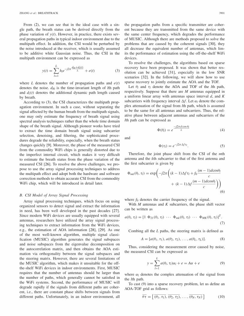
From (2), we can see that in the ideal case with a sin-gle path, the breath status can be derived directly from thephase variation of y(t). However, in practice, there exists sev-eral propagation paths in typical indoor environment due to themultipath effect. In addition, the CSI would be perturbed bythe noise introduced at the receiver, which is usually assumedto be additive white Gaussian noise. Thus, the CSI in themultipath environment can be expressed as
y(t) =L∑
l=1
hle−j2π
dl0+dl(t)λ + e(t) (3)
where L denotes the number of propagation paths and e(t)denotes the noise. dl0 is the time-invariant length of lth pathand dl(t) denotes the additional dynamic path length causedby breath.
According to (3), the CSI characterizes the multipath prop-agation environment. In such a case, without separating thesignal affected by the human breath from the multipath signals,one may only estimate the frequency of breath signal usingspectral analysis techniques rather than the whole time domainshape of the breath signal. Although pioneer works have triedto extract the time domain breath signal using subcarrierselection, denoising, and filtering, the sophisticated proce-dures degrade the reliability, especially, when the breath statuschanges quickly [9]. Moreover, the phase of the measured CSIfrom the commodity WiFi chips is generally distorted due tothe imperfect internal circuit, which makes it very difficultto estimate the breath status from the phase variation of themeasured CSI [26]. To resolve the above challenges, we pro-pose to use the array signal processing techniques to addressthe multipath effect and adopt both the hardware and softwarecorrection methods to obtain accurate CSI from the commodityWiFi chip, which will be introduced in detail later.
B. CSI Model of Array Signal Processing
Array signal processing techniques, which focus on usingorganized sensors to detect signal and extract the informationin need, has been well developed in the past decades [27].Since modern WiFi devices are usually equipped with severalantennas, researchers have utilized the array signal process-ing techniques to extract information from the WiFi devices,e.g., the estimation of AOA information [28], [29]. As oneof the most well-known algorithm, multiple signal classi-fication (MUSIC) algorithm generates the signal subspacesand noise subspaces from the eigenvalue decomposition onthe autocorrelation matrix, and then obtains the AOA esti-mation via orthogonality between the signal subspaces andthe steering matrix. However, there are several limitations ofthe MUSIC algorithm, which makes it unsuitable for the off-the-shelf WiFi devices in indoor environments. First, MUSICrequires that the number of antennas should be larger thanthe number of paths, which generally cannot be satisfied inthe WiFi systems. Second, the performance of MUSIC willdegrade rapidly if the signals from different paths are coher-ent, i.e., there are constant phase shifts between signals fromdifferent paths. Unfortunately, in an indoor environment, all
the propagation paths from a specific transmitter are coher-ent because they are transmitted from the same device withthe same center frequency, which degrades the performanceof MUSIC. Although there are methods proposed to solve theproblems that are caused by the coherent signals [30], theyall decrease the equivalent number of antennas, which lim-its the performance of estimation using the off-the-shelf WiFidevices.
To resolve the challenges, the algorithms based on sparserecovery have been proposed. It was shown that better res-olution can be achieved [31], especially in the low SNRscenarios [32]. In the following, we will show how to usesparse recovery to jointly estimate the AOA and the TOF.
Let θl and τl denote the AOA and TOF of the lth path,respectively. Suppose that there are M antennas equipped ina uniform linear array with antennas space interval d, and Ksubcarriers with frequency interval �f . Let αl denote the com-plex attenuation of the signal from lth path, which is assumedto be the same for all antennas and subcarriers. Thus, the rel-ative phase between adjacent antennas and subcarriers of thelth path can be expressed as
�(θl) = e−j2πd cos θl
λ (4)
and
�(τl) = e−j2π�f τl . (5)
Therefore, the joint phase shift from the CSI of the mthantenna and the kth subcarrier to that of the first antenna andthe first subcarrier is given by
�mk(θl, τl) = exp
(−j2π
((k − 1)�f τl + f0
(m − 1)dcosθl
c
+ (k − 1)�f(m − 1)dcosθl
c
))
(6)
where f0 denotes the carrier frequency of the signal.With M antennas and K subcarriers, the phase shift vector
can be written as
a(θl, τl) = [1 �21(θl, τl) · · · �mk(θl, τl) · · · �MK(θl, τl)]T .
(7)
Combing all the L paths, the steering matrix is defined as
A = [a(θ1, τ1), a(θ2, τ2), . . . , a(θL, τL)]. (8)
Thus, considering the measurement error caused by noise,the measured CSI can be expressed as
y =L∑
l=1
a(θl, τl)αl + e = Aα + e (9)
where αl denotes the complex attenuation of the signal fromthe lth path.
To cast (9) into a sparse recovery problem, let us define anAOA-TOF grid as follows:
θτ = [(θ1, τ1), (θ2, τ2), . . . , (θN, τN)
](10)

3902 IEEE INTERNET OF THINGS JOURNAL, VOL. 6, NO. 2, APRIL 2019
where N denotes the number of grid points. The overline isintroduced to distinguish the grid points and actual paths.
Similar to (7), the phase shift vector of the grid can bewritten as
a(θn, τn) = [1 �21(θn, τn) · · · �mk(θn, τn) · · · �MK(θn, τn)]T .
(11)
According to (8) and (11), the new steering matrix whichcontains all the grid points can be written as
A = [a(θ1, τ1), a(θ2, τ2), . . . , a(θN, τN)
]. (12)
Thus, the measured CSI and the complex attenuation vectorcan be expressed as
y = Aα + e (13)
with α being the complex attenuation vector
α = [α1, α2, . . . , αN] (14)
where αn equals to the complex attenuation coefficient if thereexists signal with the AOA of θn and TOF of τn, otherwise,αn equals to zero. Thus, there are at most L nonzero elementswhich correspond to the L paths. Apparently, the number ofgrid points can be much larger than L, i.e., L � N, whichmeans that α is a sparse vector. As a result, the problemcan be solved using minimum norm methods [31], and theoptimization problem can be formulated as follows:
min ||α||1s.t. ||y − Aα||22 ≤ β (15)
where β is the parameter determined by the noise level. Oncethe minimal norm problem been solved, we can obtain A fromA by selecting the columns of which αn is nonzero.
C. Breath Rate Estimation Based on Sparse Estimation
In the section above, we have introduced the model ofjointly estimating AOA-TOF based on the sparse recovery. Toextract the signal variation caused by breath, a straightforwardapproach is to estimate the AOA-TOF of the received sig-nal at different time slots independently and obtain the breathinformation from the AOA-TOF variation. However, since thedisplacement caused by breath is at the centimeter scale, theAOA variation resulted from the displacement is negligiblewhile the TOF variation is also very small. To estimate thebreath rate by the TOF variation directly, the grid of TOFshould be intensive enough, i.e., the TOF grid needs to be setat the millimeter scale, which makes the computation com-plexity too high. Also, treating samples at different time slotsindependently does not fully utilize the correlation of data intime domain.
Since the AOA-TOF changes slowly compared with thespeed of transmitting packets, we are motivated to combinethe samples at different slots to obtain robust estimation.However, combining the samples at different slots directlywould increase the computation cost dramatically, whichmakes it unapplicable to practical systems. To resolve theproblem, we utilize the l1-SVD algorithm proposed in [31]
to improve the accuracy and robustness of the AOA-TOF esti-mation. The l1-SVD algorithm [31] is a tractable approach touse a large number of time samples coherently. The idea isto decompose the data matrix into the signal and noise sub-spaces, and reformulate the problem with reduced dimensionsinto the multiple sample sparse spectrum estimation problem.
Let Y denote T consecutive time samples of y(t). Takingthe SVD on Y , we have
Y = UV′. (16)
Let us keep the reduced MK × L dimensional matrixYSV = UDL = YVDL, where DL = [IL0′], IL is a L×L iden-tity matrix, and 0 is a L×(T−L) matrix of zeros. Similarly, letX and E denote T consecutive samples of α(t) and e(t), respec-tively, and define XSV = XVDL and ESV = EVDL. Then, wehave
YSV = AXSV + ESV. (17)
With the SVD, the size of the problem is reduced fromT blocks of data to L, where L � T . Note that the formof (17) is the same as that of (9), which means that it could beeffectively solved by the minimal norm method [31]. Althoughthe formulation of SVD uses the information about the numberof paths, L, it has been observed that incorrect determination ofL has no catastrophic consequences [31]. Once we obtain theestimation of AOA-TOF, the complex attenuation coefficientcan be derived, which is given by
α(t) = A†y(t) (18)
where A† denotes the pseudo-inverse of A. Note that A is thesteering matrix in (8), which is obtained in the last sectionby jointly estimating AOA-TOF and selecting the columns ofA, where the corresponding complex attenuation coefficient isnonzero. The phase variation of α(t) corresponds to the minordisplacement caused by breath directly, which can be utilizedto track the breath.
III. PERFORMANCE ANALYSIS
In this section, we discuss the performance of the sparserecovery-based AOA-TOF estimation. Specifically, we mainlyfocus on the capability of distinguishing the multipath com-ponents. We use the block coherence proposed in [34], whichcan be calculated directly from the dictionary, i.e., the AOA-TOF grid, to evaluate the performance of the estimation. Inthis paper, we set the block size in [34] as 1. Thus, the blockcoherence of a grid A, which measures the similarity betweenits elements, is defined as
μB = max(p �=r)
∣∣∣∣a(θp, τp
)Ha(θr, τr)
∣∣∣∣. (19)
To efficiently recover the signal, the block coherence needsto satisfy the following condition [34]:
L <μ−1
B + 1
2(20)
where L denotes the number of paths.Here, we only discuss the optimal condition that the com-
ponent of the grid is well selected, i.e., we only consider the

ZHANG et al.: BREATHTRACK 3903
Fig. 2. Distribution of μB under different AOA-TOF conditions.
coherence between different paths and explore the fact thatunder which condition different paths can be separated. Wefirst consider the case that there are two paths in the envi-ronment. In such a case, the coherence between two paths isgiven by
μB = a(θ1, τ1)Ha(θ2, τ2). (21)
From (7) and (20), we can see that if two paths are wellseparated in space, i.e., the difference of their correspondingAOA and TOF is large, then the block coherence conditioncould be well satisfied. By assuming that the AOA-TOF of onepath is known, we can find out under what condition the AOA-TOF of the second path can be estimated with performanceguarantee. When L = 2, it can be derived from (24) that ifμB < 1/3, the AOA-TOF of two paths could be accuratelyestimated.
Although there are three antennas on the Intel 5300 NIC,we can only use two of them as one is used for correcting thedistorted CSI, which will be discussed in detail in the nextsection. Therefore, we consider the two-antenna scenario withspace interval of 2.6 cm. We fix the AOA-TOF of one path as90◦ and 2 m, i.e., θ1 = 90 and τ1 = 2/3×108. Then, we varythe AOA-TOF of the second path to compute the coherencedefined in (20). The results are shown in Fig. 2. The AOA-TOF of the two paths could be estimated if the second pathis under the blue area which satisfies the condition μB < 1/3.Note that it generally requires the two paths are separated by60◦ in AOA or 8 m in TOF. Since the space of the indoor envi-ronment is quite limited, the paths in the indoor environmentusually cannot satisfy such conditions, which results in esti-mation bias. Moreover, there are usually more than two pathsin the environment, which makes the situation even worse.Fortunately, the block coherence is just a sufficient conditionrather than a necessary condition. Although the coherence con-dition may not be satisfied in the indoor environment, if thereis a dominant path, e.g., a strong light of sight (LOS) path, theAOA-TOF of the dominant path could be accurately estimatedwhich is mainly because the coherence condition is always sat-isfied if there is only one path. Note that by combining theAOA and TOF estimation, the performance is improved since
(a) (b)
Fig. 3. Raw CSI phase within 100 ms. Raw CSI phase in (a) time domainand (b) frequency domain.
the joint estimation could fully utilize the resolution in bothAOA and TOF dimensions.
IV. DATA PROCESSING
In this section, we will introduce in detail the data pro-cessing steps of the proposed system. Specifically, we firstintroduce how to obtain accurate CSI. Then, we present howto extract the phase corresponding to the breath and how toestimate the breath rate.
A. Obtaining Accurate CSI for Breath Detection
Due to the hardware imperfection of commodity WiFi chips,the measured CSI is generally distorted by the internal cir-cuit. Moreover, some distortions even change rapidly withtime, which makes it difficult to obtain the accurate CSImeasurement. Existing work has found that the phases ofmeasured CSIs across packets are not correlated [26], whichlimits the application of phase variation-based wireless sens-ing. As shown in Fig. 3, the phase of measured CSI in 0.1 svaries rapidly, which makes it impossible to extract breath ratedirectly.
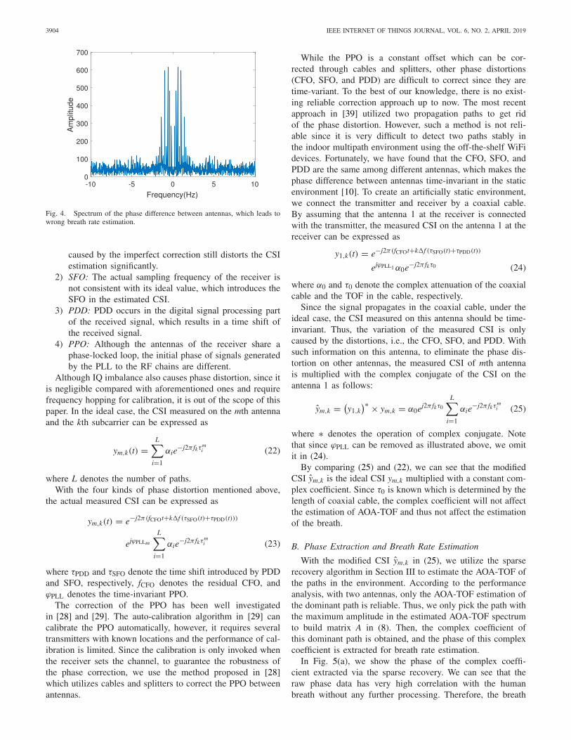
The method in [10] proposed to utilize the phase differencebetween antennas to eliminate phase distortions introducedin the internal circuit. However, this method is not accurateenough because the phase of measured CSI on all antennas areaffected by the minor displacement caused by breath. Thus, thephase difference between antennas is actually the subtractionof two periodic signals, which makes the method in [10] inac-curate. To validate this, we conduct simulations as follows.We assume a signal propagation path with length 2 m, thepath length is affected by human breath, which changes peri-odically with the frequency of 0.2 Hz. The phase differencesbetween antennas are shown in Fig. 4. We can see that thepeak of frequency does not correspond to the breath rate, i.e.,the method based on the phase differences between antennasin [10] is inaccurate.
Before discussing how to obtain accurate CSI, we first intro-duce the possible distortions that will affect the phase ofmeasured CSI. According to [38], there are mainly four kindsof phase distortions.
1) CFO: Due to the hardware limitation, the centralfrequencies of the transmitter and the receiver are notperfectly synchronized. Although the CFO has beencompensated by a CFO corrector, the residual CFO
3904 IEEE INTERNET OF THINGS JOURNAL, VOL. 6, NO. 2, APRIL 2019
Fig. 4. Spectrum of the phase difference between antennas, which leads towrong breath rate estimation.
caused by the imperfect correction still distorts the CSIestimation significantly.
2) SFO: The actual sampling frequency of the receiver isnot consistent with its ideal value, which introduces theSFO in the estimated CSI.
3) PDD: PDD occurs in the digital signal processing partof the received signal, which results in a time shift ofthe received signal.
4) PPO: Although the antennas of the receiver share aphase-locked loop, the initial phase of signals generatedby the PLL to the RF chains are different.
Although IQ imbalance also causes phase distortion, since itis negligible compared with aforementioned ones and requirefrequency hopping for calibration, it is out of the scope of thispaper. In the ideal case, the CSI measured on the mth antennaand the kth subcarrier can be expressed as
ym,k(t) =L∑
i=1
αie−j2π fkτm
i (22)
where L denotes the number of paths.With the four kinds of phase distortion mentioned above,
the actual measured CSI can be expressed as
ym,k(t) = e−j2π(fCFOt+k�f (τSFO(t)+τPDD(t)))
ejϕPLLm
L∑
i=1
αie−j2π fkτm
i (23)
where τPDD and τSFO denote the time shift introduced by PDDand SFO, respectively, fCFO denotes the residual CFO, andϕPLL denotes the time-invariant PPO.
The correction of the PPO has been well investigatedin [28] and [29]. The auto-calibration algorithm in [29] cancalibrate the PPO automatically, however, it requires severaltransmitters with known locations and the performance of cal-ibration is limited. Since the calibration is only invoked whenthe receiver sets the channel, to guarantee the robustness ofthe phase correction, we use the method proposed in [28]which utilizes cables and splitters to correct the PPO betweenantennas.
While the PPO is a constant offset which can be cor-rected through cables and splitters, other phase distortions(CFO, SFO, and PDD) are difficult to correct since they aretime-variant. To the best of our knowledge, there is no exist-ing reliable correction approach up to now. The most recentapproach in [39] utilized two propagation paths to get ridof the phase distortion. However, such a method is not reli-able since it is very difficult to detect two paths stably inthe indoor multipath environment using the off-the-shelf WiFidevices. Fortunately, we have found that the CFO, SFO, andPDD are the same among different antennas, which makes thephase difference between antennas time-invariant in the staticenvironment [10]. To create an artificially static environment,we connect the transmitter and receiver by a coaxial cable.By assuming that the antenna 1 at the receiver is connectedwith the transmitter, the measured CSI on the antenna 1 at thereceiver can be expressed as
y1,k(t) = e−j2π(fCFOt+k�f (τSFO(t)+τPDD(t))
ejϕPLL1 α0e−j2π fkτ0 (24)
where α0 and τ0 denote the complex attenuation of the coaxialcable and the TOF in the cable, respectively.
Since the signal propagates in the coaxial cable, under theideal case, the CSI measured on this antenna should be time-invariant. Thus, the variation of the measured CSI is onlycaused by the distortions, i.e., the CFO, SFO, and PDD. Withsuch information on this antenna, to eliminate the phase dis-tortion on other antennas, the measured CSI of mth antennais multiplied with the complex conjugate of the CSI on theantenna 1 as follows:
ym,k = (y1,k
)∗ × ym,k = α0ej2π fkτ0
L∑
i=1
αie−j2π fkτm
i (25)
where ∗ denotes the operation of complex conjugate. Notethat since ϕPLL can be removed as illustrated above, we omitit in (24).
By comparing (25) and (22), we can see that the modifiedCSI ym,k is the ideal CSI ym,k multiplied with a constant com-plex coefficient. Since τ0 is known which is determined by thelength of coaxial cable, the complex coefficient will not affectthe estimation of AOA-TOF and thus not affect the estimationof the breath.
B. Phase Extraction and Breath Rate Estimation
With the modified CSI ym,k in (25), we utilize the sparserecovery algorithm in Section III to estimate the AOA-TOF ofthe paths in the environment. According to the performanceanalysis, with two antennas, only the AOA-TOF estimation ofthe dominant path is reliable. Thus, we only pick the path withthe maximum amplitude in the estimated AOA-TOF spectrumto build matrix A in (8). Then, the complex coefficient ofthis dominant path is obtained, and the phase of this complexcoefficient is extracted for breath rate estimation.
In Fig. 5(a), we show the phase of the complex coeffi-cient extracted via the sparse recovery. We can see that theraw phase data has very high correlation with the humanbreath without any further processing. Therefore, the breath

ZHANG et al.: BREATHTRACK 3905
(a) (b)
Fig. 5. Phase extracted by the proposed system. (a) Phase before the Hampelfilter. (b) Phase after the Hampel filter.
rate estimation does not require sophisticated denoising, filter-ing and/or approximating processing steps as in the previousworks [8]–[10]. Since the dc component of the phase variationis large, which may affect the breath rate estimation, we utilizethe Hampel filter to remove it [10]. The window size is setas 100 samples and the threshold is set to be 0.01. As shownin Fig. 5(b), the dc component of phase variation is perfectlyremoved. To further suppress the low frequency noise, we usean FIR highpass filter with the cutoff frequency 0.05 Hz, whichis determined by the lowest breath frequency of human. Then,we simply pick the peak of FFT spectrum of the filtered phasedata as the estimation of breath rate.
V. EXPERIMENTS RESULTS
In this section, we conduct extensive real experiments toevaluate the performance of the proposed system. Specifically,we first illustrate the performance of the AOA estimation inthe proposed system. Then, we show the advantages of theproposed system by comparing the raw phase data obtainedin the proposed system with those obtained using existingmethods which use signal variation on subcarriers to estimatebreath rate [8]–[10]. Finally, we show the performance of theproposed system under different experimental settings.
We use two desktop computers equipped with the Intel 5300NIC as the transmitter and the receiver. The Linux 802.11nCSI tool [37] is installed on the Ubuntu desktop 14.04 LTS OSfor both the transmitter and the receiver. We randomly choosechannel 62, i.e., 5.31 GHz center frequency with the 40 MHzbandwidth, as our experimental band. The receiver operates inthe “monitor” mode. It is equipped with a uniform linear arraywhich is composed of three omnidirectional antennas, whilewe only use two of them since one of the port is connectedwith the transmitter directly. The space interval of the antennasis 2.6 cm, which is about the half wavelength. The transmit-ter operates in the “inject” mode using one omnidirectionalantenna. It injects 20 packets per second. The transmitted sig-nal is first divided into two parts using a microwave powersplitter: one is fed into the transmit antenna and the other isfed into an attenuator which is connected with the receiver viaa coaxial cable. The AOA-TOF estimation problem with thesparse recovery formulation is solved using the CVX tool [36].The AOA grid spans [1◦, 180◦] with Nθ = 90 and the TOFgrid spans [−15 m, 15 m] with Nτ = 31.
A total of eight different participants were invited. Theperformance of the system is evaluated by comparing the
Fig. 6. Layout of the meeting room.
Fig. 7. Performance of the AOA estimation.
Fig. 8. Median error of breath rate estimation under different breathfrequencies.
estimated breath rate with the ground truth. To obtain theground truths, participants are asked to synchronize theirbreaths with the metronome on their cellphones. Besidesthe controlled breath, participants are also asked to breathnaturally and count their breaths manually. Experiments areconducted in a 5 m × 8 m meeting room. The layout of themeeting room is shown in Fig. 6, where Tx and Rx denotethe transmitter and receiver antennas, respectively. To test theimpact of the distance between transmitter and receiver, wefix the position of transmitter antenna and vary the location ofthe receiver antennas. In the NLOS scenario, the transmitterantenna is deployed about 50 cm outside the door. Note thatthe meeting room is crowded of chairs, computers and other

3906 IEEE INTERNET OF THINGS JOURNAL, VOL. 6, NO. 2, APRIL 2019
(a) (b) (c) (d)
Fig. 9. Case when one person breaths 15 times per minute. (a) Raw phase extracted from the dominant path. Raw phase of the CSI on subcarrier (b) 10,(c) 20, and (d) 30.
(a) (b) (c) (d)
Fig. 10. Case when one person holds the breath first and then breath normally. (a) Raw phase extracted from the dominant path. Raw phase of the CSI onsubcarrier (b) 10, (c) 20, and (d) 30.
devices, which are not shown in Fig. 6. To guarantee that thedominant path is affected by human breath, the participant sitsbetween the transmitter and the receiver in all experiments.
A. Performance of AOA Estimation
In the first experiment, we show the performance of theAOA estimation. The transmitter is about 3 m away from thereceiver and the ground truth AOA varies from 60◦ to 120◦.The empirical cumulative distribution function (CDF) is shownin Fig. 7, which is consistent with the performance evaluationin [32]. From Fig. 7, we can see that the estimation error ofthe AOA is smaller than 20◦, and such an estimation bias doesnot affect the extraction of the phase variation significantly aswe found through both simulation and experiments.
B. Performance of Breath Rate Estimation
We first consider the LOS scenario with a single person, i.e.,there is an LOS path between the transmitter and the receiverwhile only one person exists in the environment. The transmit-ter and the receiver are separated 2 m away. The participantsits in the midpoints of the transmitter and the receiver. Toshow the robustness of the proposed system, they are asked tobreath with the frequency of 0.2, 0.25, and 0.33 Hz in differentexperiments, respectively. The median accuracy of the breathrate estimation of three frequencies is shown in Fig. 8. Wecan see that the proposed method can achieve very accuratebreath rate estimation, above 99.5%, in this scenario.
Since most existing methods seem to have reasonableperformance in estimating the breath rate under simple set-tings, to show the advantages of the propose system, wecompare the raw phase variation data of different subcarri-ers and the raw phase extracted by the proposed system. We
first ask the participant to breath with 15 BPM and the resultsare shown in Fig. 9. It can be seen clearly from Fig. 9(a) thatthere are 15 periods. On the contrary, although the phase ofthe subcarriers do show some periodicity, it is difficult to rec-ognize the breath period based on the phase variation on thesubcarriers as shown in Fig. 9(b)–(d). Note that we do checkthe phase variation of all different subcarriers, however, noneof them could be used to judge the breath period. In all exper-iments of the proposed system, the raw phase data is directlyrelated to the breath and the frequency of the breath can beeasily estimated in the way similar to Fig. 9(a) if there is noother specific illustration.
To further illustrate the advantages of proposed system, weshow two more experiments in Figs. 10 and 11. Since the sta-tus of human breath may change rapidly due to many factors,such as speaking, moving or even some unconscious behav-iors, it will be much more significant if one could identifythe whole breath status rather than just estimate the rate. InFig. 10, the participant is asked to hold the breath for 30 sfirst, then take a deep breath, and finally breath normally. InFig. 11, the participant is asked to breath normally first, andthen hold the breath. As shown in Figs. 10(a) and 11(a), theproposed system can perfectly capture such minor and fastchange of the whole breath status. However, similar to theresults in Fig. 9, we cannot judge the breath status directlyfrom the phase variation on different subcarriers as shownin (b), (c), and (d) of Figs. 10 and 11. Note that the peaksin Fig. 11(c) and (d) are caused by the phase wrapping in[−2π, 2π ]. We also evaluate the case when there is no per-son existing in the environment and the results are shown inFig. 12. We can see from Fig. 12(a) that the phase variationextracted from the dominant path is very stable. However, fromthe phase variation of different subcarriers, it is very hard to

ZHANG et al.: BREATHTRACK 3907
(a) (b) (c) (d)
Fig. 11. Case when one person breaths normally first and then holds the breath. (a) Raw phase extracted from the dominant path. Raw phase of the CSI onsubcarrier (b) 10, (c) 20, and (d) 30.
(a) (b) (c) (d)
Fig. 12. Case when no person exists in the environment. (a) Raw phase extracted from the dominant path. Raw phase of the CSI on subcarrier (b) 10, (c) 20,and (d) 30.
Fig. 13. Median error of breath rate estimation under different conditionsof the transmitter–receiver distance and the NLOS scenario.
distinguish whether the signal is affected by human breath ornot. This is because with or without human breath, the timedomain phase variation does not show significant difference,especially for subcarrier 20 and subcarrier 30. It seems that thesignal is still affected by some periodic displacement as shownin Fig. 12(c) and (d). According to the subcarrier selectionstrategy used in [9], such subcarriers will be selected as “highperiodicity” ones and used to calculate breath rate, which willlead to wrong breath detection.
C. Impact of Distance Between Transmitter and Receiver
In this section, we evaluate the performance of the proposedsystem under different distances between the transmitter andthe receiver. The participants sit in the midpoints of the trans-mitter and the receiver, breath with the frequency of 0.25 Hz.The performance of breath rate estimation is shown in Fig. 13.As shown in the figure, the proposed system could achieve
Fig. 14. Raw phase variation when the participant stands up at 24th secondand sits down at 32nd second.
high accuracy when the distance varies from 1 to 4 m.Although we do conduct the experiments under the scenariothat the transmitter and the receiver are separated by 5 m,the packet loss rate increases rapidly. In more than ten exper-iments, the packet loss rate varies from 50% to 90%, dueto which the measured CSI could not be used to estimatethe breath rate. Some modifications on the CSI tool may beneeded to reduce the packet loss rate to make the measuredCSI useful, which, however, is out of the scope of this paper.
D. Impact of People’s Motion
Since the phase of the signal is sensitive to the minordisplacements in the environment, we explore the impact ofpeople’s motion in this section. As shown in Fig. 14, largemotions do have significant influence on the phase variation.Thus, we use a time window which is introduced in [7] withthe length of 10 s to remove the data affected by the large

3908 IEEE INTERNET OF THINGS JOURNAL, VOL. 6, NO. 2, APRIL 2019
Fig. 15. Median error of breath rate estimation with the interference ofmotion.
Fig. 16. Sketch of human in different orientations.
motion based on the variance. Participants sit between thetransmitter and the receiver, and breath with the frequency of0.25 Hz. They are asked to chat with friends using cellphone,shake their heads, stand up and turn around in the experi-ments. The performance of breath rate estimation is shown inFig. 15. As shown in the figure, using cellphone or shakingheads does not affect the breath rate estimation. Motions likestanding up or turning around does affect the performance ofbreath rate estimation a little bit, which is mainly because thesystem could only use the data that is not affected by the largemotion to calculate breath rate and the motions like standingup or turning around reduce the useful data more significantly.
E. Impact of Human’s Orientation
It has been found in previous work that the human’s orien-tation will affect the performance of the breath estimation [9],due to the different amplitude of displacement caused bybreath in different orientations. Thus, we conduct a series ofexperiments to evaluate the impact of human’s orientation inthis section. As shown in Fig. 16, the participant is asked tosit facing the receiver antenna, back to the receiver antenna,toward the left and right side of receiver antenna, respectively.The performance is shown in Fig. 17. We can see that benefit-ing from the high sensitivity of the signal phase, the orientationdoes not affect much the breath rate estimation of the proposedsystem.
F. Breath Rate Estimation in NLOS Scenarios
For indoor localization applications, the AOA-TOF-basedalgorithms require the LOS path to accurately locate the trans-mitter. In the NLOS scenarios, it cannot locate the transmitter
Fig. 17. Median error of breath rate estimation with different orientationsof human.
Fig. 18. Raw phase extracted from the dominant path in the NLOS scenario.
accurately since the estimated AOA-TOF does not correspondto the location of transmitter directly. Nevertheless, since ourgoal is to extract the signal of the dominant path in the environ-ment rather than locate the transmitter, the proposed systemstill works in the NLOS scenarios. In this experiment, thetransmitter is moved outside the meeting room. The partici-pant sits 1 m from the receiver and breath with the frequencyof 0.25 Hz. The performance of the breath rate estimation isshown in Fig. 13. As shown in the figure, the proposed systemcould also work in the NLOS scenarios with high accuracy.While the breath rate estimation is not affected significantly inNLOS case, the raw phase variation becomes more unstablecompared to the LOS scenarios, as shown in Fig. 18. This ismainly due to the extra attenuation in the NLOS scenarios.
G. Comparison of the CSI Amplitude and Phase
In this section, we compare the amplitude and phase vari-ation extracted by the proposed system to demonstrate thatCSI phase is more sensitive to human breath compared withtbe CSI amplitude. For the sake of fairness, both amplitude,and phase are normalized to [0, 1]. As shown in Fig. 19, it ismore difficult to recognize breath period from the amplitudevariation. This is because the amplitude variation caused byhuman breath is too small to capture according to the radarrange equation [35], which makes it suffer from random noise.

ZHANG et al.: BREATHTRACK 3909
(a) (b)
Fig. 19. Comparison of CSI amplitude and phase variation. (a) Normalizedamplitude variation. (b) Normalized phase variation.
Fig. 20. Comparison of breath rate estimation accuracy.
Fig. 21. Sketch of human at different locations.
In contrast, the phase variation is linear with the minor dis-placement caused by human breath, which makes it moresensitive and suitable for breath status tracking. We show theCDFs of breath rate estimation error in Fig. 20. We can seethat the performance with CSI phase is much better than thatwith CSI amplitude.
H. Impact of Human Locations
In previous sections, we assume that the person stays closeto the link of the transmitter and receiver to make sure thatthe human breath would have enough impacts on the receivedsignal. Here, we conduct experiments to evaluate the impactof the distance from the human location to the transmitter–receiver link. The person initially stays at the midpoint of thetransmitter and receiver, and then moves away perpendicu-larly as shown in Fig. 21. The transmitter and receiver areseparated by 2.2 m. The breath rate estimation accuracy ver-sus the distance between the person and the midpoint is shownin Fig. 22. The proposed system could provide very accuratebreath rate estimation when the distance is within 2 m and theaccuracy begins degraded with a larger distance. The phasevariation when person stays with a different distance is shown
Fig. 22. Estimation accuracy versus the distance.
(a) (b)
(c) (d)
Fig. 23. Phase variation when the person stays with a different distance.Phase variation when human body is (a) 0.4 m away, (b) 1.2 m away, (c) 2 maway, and (d) 2.8 m away.
in Fig. 23. The phase variation becomes smaller, due to whichit is more difficult to recognize breath period with a largerdistance. This is mainly because the reflected signal becomesweaker and has less impact on the received signal when theperson moves away.
I. Multiperson Scenario
The proposed system can also work in the multipersonscenario under the assumption that the breath rate of differ-ent participants are different. Three participants are invited tobreath with the frequency of 0.2, 0.25, and 0.33 Hz, respec-tively. The performance of the breath rate estimation for thethree participants are shown in Fig. 24. Due to the fact that thedistances between the participants and the receiver are differ-ent, the reflected signal strengths are different, which makesthe performance slightly different. The person 2 with 15 BPMrate is the one closest to the receiver and thus the rate estima-tion is most accurate, while person 3 with 20 BPM rate is thefarthest one from the receiver and thus the rate estimation isleast accurate.

3910 IEEE INTERNET OF THINGS JOURNAL, VOL. 6, NO. 2, APRIL 2019
Fig. 24. Median error rate of breath rate estimation in the three personsscenario.
VI. CONCLUSION
In this paper, we proposed BreathTrack, the first systemthat can track the detailed status of breath using the off-the-shelf WiFi devices. To achieve this, we proposed hardware andsoftware correction methods to remove both the time-invariantand time-varying phase distortions introduced by the hardwareimperfection of the commodity WiFi chips and thus obtainthe accurate CSI. We also proposed a joint AOA-TOF sparserecovery method to eliminate the multipath effect in the indoorenvironment and extract the information of the dominant pathto track the status of breath. Experimental results show thatBreathTrack can achieve high accurate breath rate estimationand track the detailed status of breath. The proposed systemis also applicable in other wireless sensing applications, suchas activity recognition [18], events detection [11], and speedestimation [12].
REFERENCES
[1] M. Liu and M. Huang, “Asthma pattern identification via continuousdiaphragm motion monitoring,” IEEE Trans. Multi-Scale Comput. Syst.,vol. 1, no. 2, pp. 76–84, Apr./Jun. 2015.
[2] I. Bisio, A. Delfino, A. Grattarola, F. Lavagetto, and A. Sciarrone,“Ultrasounds-based context sensing method and applications overthe Internet of Things,” IEEE Internet Things J., vol. 5, no. 5,pp. 3876–3890, Oct. 2018.
[3] I. Bisio, F. Lavagetto, M. Marchese, and A. Sciarrone, “A smartphone-centric platform for remote health monitoring of heart failure,” Int. J.Commun. Syst., vol. 28, no. 11, pp. 1753–1771, Jul. 2015.
[4] P. Verma and S. K. Sood, “Fog assisted-IoT enabled patient healthmonitoring in smart homes,” IEEE Internet Things J., vol. 5, no. 3,pp. 1789–1796, Jun. 2018.
[5] iBabyGuard. Accessed: Jun. 1, 2018. [Online]. Available:http://www.ibabyguard.com/
[6] VivoSense. Sensors: Equivital. Accessed: Jun. 1, 2018. [Online].Available: https://www.vivosense.com/portfolio/equivital/
[7] F. Adib, H. Mao, Z. Kabelac, D. Katabi, and R. C. Miller, “Smarthomes that monitor breathing and heart rate,” in Proc. ACM CHI, 2015,pp. 837–846.
[8] H. Abdelnasser, K. A. Harras, and M. Youssef, “UbiBreathe: A ubiq-uitous non-invasive WiFi-based breathing estimator,” in Proc. ACMMobiHoc, 2015, pp. 277–286.
[9] X. Liu, J. Cao, S. Tang, J. Wen, and P. Guo, “Contactless respira-tion monitoring via off-the-shelf WiFi devices,” IEEE Trans. MobileComput., vol. 15, no. 10, pp. 2466–2479, Oct. 2016.
[10] X. Wang, C. Yang, and S. Mao, “PhaseBeat: Exploiting CSI phase datafor vital sign monitoring with commodity WiFi devices,” in Proc. IEEEICDCS, 2017, pp. 1230–1239.
[11] Q. Xu, Y. Chen, B. Wang, and K. J. R. Liu, “TRIEDS: Wireless eventsdetection through the wall,” IEEE Internet Things J., vol. 4, no. 3,pp. 723–735, Jun. 2017.
[12] F. Zhang, C. Chen, B. Wang, and K. J. R. Liu, “WiSpeed: A statisticalelectromagnetic approach for device-free indoor speed estimation,” IEEEInternet Things J., vol. 5, no. 3, pp. 2163–2177, Jun. 2018.
[13] C. Chen et al., “TR-BREATH: Time-reversal breathing rate estimationand detection,” IEEE Trans. Biomed. Eng., vol. 65, no. 3, pp. 489–501,Mar. 2018.
[14] Q. Y. Xu, Y. Chen, B. B. Wang, and K. J. R. Liu, “Radio biometrics:Human recognition through a wall,” IEEE Trans. Inf. Forensics Security,vol. 12, no. 5, pp. 1141–1155, May 2017.
[15] C. Chen, Y. Chen, Y. Han, H. Q. Lai, and K. J. R. Liu, “Achievingcentimeter accuracy indoor localization on WiFi platforms: A frequencyhopping approach,” IEEE Internet Things J., vol. 4, no. 1, pp. 111–121,Feb. 2017.
[16] C. Chen et al., “Achieving centimeter accuracy indoor localization onWiFi platforms: A multi-antenna approach,” IEEE Internet Things J.,vol. 4, no. 1, pp. 122–134, Feb. 2017.
[17] C. Chen, Y. Han, Y. Chen, and K. J. R. Liu, “Indoor global positioningsystem with centimeter accuracy using Wi-Fi,” IEEE Signal Process.Mag., vol. 33, no. 6, pp. 128–134, Nov. 2016.
[18] Y. Gu, F. Ren, and J. Li, “PAWS: Passive human activity recognitionbased on WiFi ambient signals,” IEEE Internet Things J., vol. 3, no. 5,pp. 796–805, Oct. 2016.
[19] S. Di Domenico, M. De Sanctis, E. Cianca, F. Giuliano, and G. Bianchi,“Exploring training options for RF sensing using CSI,” IEEE Commun.Mag., vol. 56, no. 5, pp. 116–123, May 2018.
[20] W. Wang, A. X. Liu, M. Shahzad, K. Ling, and S. Lu, “Device-free human activity recognition using commercial WiFi devices,”IEEE J. Sel. Areas Commun., vol. 35, no. 5, pp. 1118–1131,May 2017.
[21] W. Wang, A. X. Liu, M. Shahazad, K. Ling, and S. Lu, “Understandingand modeling of WiFi signal based human activity recognition,” in Proc.ACM Mobicom, 2015, pp. 65–76.
[22] Y. Wang et al., “E-eyes: Device-free location-oriented activity identifycation using fine-grained WiFi signatures,” in Proc. ACM Mobicom,2014, pp. 617–628.
[23] C. Wu et al., “Non-invasive detection of moving and stationaryhuman with WiFi,” IEEE J. Sel. Areas Commun., vol. 33, no. 11,pp. 2329–2342, Nov. 2015.
[24] W. Xi et al., “Electronic frog eye: Counting crowd using WiFi,” in Proc.IEEE INFOCOM, 2014, pp. 361–369.
[25] S. Di Domenico, G. Pecoraro, E. Cianca, and M. De Sanctis, “Trained-once device-free crowd counting and occupancy estimation using WiFi:A doppler spectrum based approach,” in Proc. IEEE WiMob, 2016,pp. 1–8.
[26] R. Nandakumar, B. Kellogg, and S. Gollakota, “Wi-Fi gesture recogni-tion on existing devices,” arXiv:1411.5394, 2014.
[27] H. Krim and M. Viberg, “Two decades of array signal processingresearch: The parametric approach,” IEEE Signal Process. Mag., vol. 13,no. 4, pp. 67–94, Jul. 1996.
[28] J. Xiong and K. Jamieson, “ArrayTrack: A fine-grained indoor locationsystem,” in Proc. USENIX NSDI, 2013, pp. 71–84.
[29] J. Gjengset, J. Xiong, G. McPhillips, and K. Jamieson, “Phaser: Enablingphased array signal processing on commodity WiFi access points,” inProc. ACM MobiCom, 2014, pp. 153–164.
[30] M. Kotaru, K. Joshi, D. Bharadia, and S. Katti, “SpotFi: Decimeterlevel localization using WiFi,” in Proc. ACM SIGCOMM, 2015,pp. 269–282.
[31] D. Malioutov, M. Cetin, and A. S. Willsky, “A sparse sig-nal reconstruction perspective for source localization with sensorarrays,” IEEE Trans. Signal Process., vol. 53, no. 8, pp. 3010–3022,Aug. 2005.
[32] W. Gong and J. Liu, “Robust indoor wireless localization using sparserecovery,” in Proc. IEEE ICDCS, 2017, pp. 847–856.
[33] E. J. Candes and M. B. Wakin, “An introduction to compressivesampling,” IEEE Signal Process. Mag., vol. 25, no. 2, pp. 21–30,Mar. 2008.
[34] Y. C. Eldar, P. Kuppinger, and H. Bolcskei, “Block-sparse signals:Uncertainty relations and efficient recovery,” IEEE Trans. SignalProcess., vol. 58, no. 6, pp. 3042–3054, Jun. 2010.
[35] B. R. Mahafza, Radar Systems Analysis and Design Using MATLAB.Boca Raton, FL, USA: CRC Press, 2002.
[36] CVX Solvers. Accessed: Jun. 1, 2018. [Online]. Available:http://cvxr.com/cvx/doc/solver.html
[37] D. Halperin, W. Hu, A. Sheth, and D. Wetherall, “Tool release:Gathering 802.11n traces with channel state information,” in Proc. ACMSIGCOMM CCR, 2011, p. 53.
[38] Y. Zhuo, H. Zhu, H. Xue, and S. Chang, “Perceiving accurate CSIphases with commodity WiFi devices,” in Proc. IEEE INFOCOM, 2017,pp. 1–9.
[39] M. Kotaru and S. Katti, “Position tracking for virtual reality usingcommodity WiFi,” in Proc. IEEE CVPR, 2017, pp. 2671–2681.

ZHANG et al.: BREATHTRACK 3911
Dongheng Zhang received the B.S. degree fromthe School of Electronic and Engineering, Universityof Electronic Science and Technology of China,Chengdu, China, in 2017. He is currently pursu-ing the Ph.D. degree at the School of Informationand Communication Engineering, University ofElectronic Science and Technology of China,Chengdu.
His current research interests include signal pro-cessing, wireless communications, and networking.
Yang Hu received the B.S. and Ph.D. degrees inelectrical engineering from the University of Scienceand Technology of China, Hefei, China, in 2004 and2009, respectively.
She was with the University of Maryland Institutefor Advanced Computer Studies, College Park,MD, USA, as a Research Associate from 2010to 2015. She is currently an Associate Researcherwith the School of Information and CommunicationEngineering, University of Electronic Science andTechnology of China, Chengdu, China. Her current
research interests include computer vision, machine learning, and multimediasignal processing.
Yan Chen (SM’14) received the bachelor’s degreefrom the University of Science and Technology ofChina, Hefei, China, in 2004, the M.Phil. degreefrom the Hong Kong University of Science andTechnology, Hong Kong, in 2007, and the Ph.D.degree from the University of Maryland at CollegePark, College Park, MD, USA, in 2011.
He was with Origin Wireless Inc., Greenbelt, MD,USA, as a Founding Principal Technologist. Since2015, he has been a Full Professor with the Schoolof Information and Communication Engineering,
University of Electronic Science and Technology of China. His currentresearch interests include multimedia, signal processing, game theory, andwireless communications.
Dr. Chen was a recipient of multiple honors and awards, including theBest Student Paper Award of PCM in 2017, the Best Student Paper Awardof IEEE ICASSP in 2016, the Best Paper Award of IEEE GLOBECOMin 2013, the Future Faculty Fellowship and Distinguished DissertationFellowship Honorable Mention from the Department of Electrical andComputer Engineering in 2010 and 2011, the Finalist of the Dean’s DoctoralResearch Award from the A. James Clark School of Engineering, Universityof Maryland at College Park in 2011, and the Chinese Government Awardfor outstanding students abroad in 2010.
Bing Zeng (M’91–SM’13–F’16) received theB.Eng. and M.Eng. degrees in electronic engineer-ing from the University of Electronic Science andTechnology of China (UESTC), Chengdu, China, in1983 and 1986, respectively, and the Ph.D. degree inelectrical engineering from the Tampere Universityof Technology, Tampere, Finland, in 1991.
He was a Post-Doctoral Fellow with theUniversity of Toronto, Toronto, ON, Canada, from1991 to 1992, and a Researcher with ConcordiaUniversity, Montreal, QC, Canada, from 1992 to
1993. He then joined the Hong Kong University of Science and Technology(HKUST), Hong Kong. After 20 years of service with HKUST, he returned toUESTC in 2013, through China’s 1000-Talent-Scheme. With UESTC, he leadsthe Institute of Image Processing to work on image and video processing, 3-Dand multiview video technology, and visual big data. During his tenure withHKUST and UESTC, he has graduated over 30 master’s and Ph.D. students.He received about 20 research grants, holds 8 international patents, and hasauthored or co-authored over 260 papers. Three representing works are asfollows: one paper on fast block motion estimation, published in the IEEETRANSACTIONS ON CIRCUITS AND SYSTEMS FOR VIDEO TECHNOLOGY
(TCSVT) in 1994, has over SCI 1000 citations (over 2200 Google citations)and currently stands at the eighth position among all papers published in thisTRANSACTIONS; one paper on smart padding for arbitrarily shaped imageblocks, published in the IEEE TRANSACTIONS ON CIRCUITS AND SYSTEMS
FOR VIDEO TECHNOLOGY in 2001 led to a patent that has been successfullylicensed to companies; and one paper on directional discrete cosine trans-form, published in the IEEE TRANSACTIONS ON CIRCUITS AND SYSTEMS
FOR VIDEO TECHNOLOGY in 2008.Dr. Zeng was a recipient of the 2011 IEEE CSVT TRANSACTIONS Best
Paper Award, the Best Paper Award at ChinaCom three times (2009 Xi’an,2010 Beijing, and 2012 Kunming), the Second Class Natural Science Award(the first recipient) from the Chinese Ministry of Education in 2014, andthe Best Associate Editor Award in 2011. He served as an Associate Editorfor the IEEE TRANSACTIONS ON CIRCUITS AND SYSTEMS FOR VIDEO
TECHNOLOGY for eight years. He was the General Co-Chair of VCIP-2016and PCM-2017.
![Dynamic Image Prediction Using Principal Component and ... · teer breath hold, beam tracking, tracking with fiducial or infrared markers etc [2]. Long-term breath. -hold tech- ...](https://static.fdocuments.in/doc/165x107/5eb7d3c1cc13dd14e9599e65/dynamic-image-prediction-using-principal-component-and-teer-breath-hold-beam.jpg)