
Breaking the ice: de-icing power transmission lines with high ...
7
Breaking the ice: de-icing power transmission lines with high-frequency, high-voltage excitation Sullivan, C. R. Petrenko, V. F. McCurdy, J. D. V. Kozliouk From IEEE Industry Applications Magazine, vol. 9, no. 5, pp. 49–54. c 2003 IEEE. Personal use of this material is permitted. However, permission to reprint or republish this material for advertising or promotional purposes or for creating new collective works for resale or redistribution to servers or lists, or to reuse any copyrighted component of this work in other works must be obtained from the IEEE.
Transcript of Breaking the ice: de-icing power transmission lines with high ...

Breaking the ice: de-icing power transmission
lines with high-frequency, high-voltage excitation
Sullivan, C. R.Petrenko, V. F.McCurdy, J. D.
V. Kozliouk
From IEEE Industry Applications Magazine, vol. 9, no. 5, pp. 49–54.
c©2003 IEEE. Personal use of this material is permitted. However, permissionto reprint or republish this material for advertising or promotional purposes orfor creating new collective works for resale or redistribution to servers or lists,or to reuse any copyrighted component of this work in other works must beobtained from the IEEE.

CING OF POWER TRANSMISSION
lines during winter storms is a persistent
problem that causes outages and costs mil-
lions of dollars in repair expenses.
High-frequency excitation at approximately 8-200 kHz
has been proposed as a method to melt ice [1], [2]. The
method works by a combination of two mechanisms. At
these frequencies, ice is a lossy dielectric, causing heating
directly in the ice. In addition, skin effect causes current to
flow only in a thin layer on the surface of the line, causing
resistive losses and consequent heating.
In this article, we describe the design of systems to im-
plement this method on lines up to 1,000 km long. We
also report experimental tests of deicing of a 1-m simulated
line using dielectric losses in ice using a prototype system
that applies 33-kV, 100-kHz power.
The overall system is illustrated in Figure 1. It could be de-
ployed in two different ways. For lines with chronic icing
problems, or where icing is likely, and high reliability is de-
sired, the system could be permanently installed connected to
a section of line, with traps at either end of the section to con-
fine the excitation to a controlled region. Alternatively, it 49
1077-2618/03/$17.00©2003 IEEE
IEE
EIN
DU
ST
RY
AP
PL
ICA
TIO
NS
MA
GA
ZIN
E•
SE
PT
|O
CT
20
03
•W
WW
.IEE
E.O
RG
/IA
S
DEICING powertransmission lines withHIGH-FREQUENCY,HIGH-VOLTAGEexcitation.
B Y C H A R L E S R . S U L L I V A N ,
V I C T O R F . P E T R E N K O ,
J O S H U A D . M C C U R D Y ,
& V A L E R I K O Z L I O U K
© ARTVILLE
I

could be mounted in trucks that could be dispatched in anemergency to “rescue” a section of line from icing. A set ofthree trucks could carry a source and two traps.
Principle of Ice Dielectric HeatingWith ice modeled as a lossy dielectric material, the equiva-lent circuit for a short section of transmission line coated
with ice is as shown in Figure 2. The component values forRice and Cice may be calculated from models of the electricalproperties of ice given in [3]. For frequencies as low as 12kHz, the dielectric properties become sufficiently lossy togenerate significant heating. As frequency increases, thevoltage needed to produce adequate loss drops. A preferredrange of operation is often around 20-150 kHz, as is de-tailed in the next section, although lower frequencies canalso be used in order to avoid regulated frequency ranges.
Achieving Uniform HeatingExciting a transmission line with high-frequency powerwill produce standing waves unless the line is terminatedwith a matched impedance at the far end. With standingwaves, either ice-dielectric heating or skin-effect resistiveheating would, acting alone, result in uneven heating.
A possible solution to this problem is to terminate theline, producing running, rather than standing, waves.However, running waves entail energy flow that is typi-cally much larger than the energy dissipation in the ice.This energy must be processed by the power source at oneend and absorbed by the termination at the other end.Thus, the power capability of the source must be increasedwell beyond the power required for heating. The termina-tion must be capable of dissipating or recycling this poweras well. Thus, this is an expensive solution, both in terms ofthe cost of the equipment and, if it is not recycled, the costof the energy dissipated in the termination.
A better solution is to use standing waves that apply thetwo heating effects in a complementary fashion. Ice-dielec-tric heating occurs most strongly at the voltage antinodes inthe standing wave pattern, whereas skin-effect heating oc-curs most strongly at the current antinodes. Thus, the twoare complementary, and, if the magnitudes are in the properratio, the total heating can be made uniform over the lengthof the line.
The ratio of the two heating effects depends on many fac-tors, including the type of conductors, their geometrical con-figuration, and the thickness of the ice. The examples beloware based on a 230-kV, two-circuit transmission line configu-ration in which the conductor-to-conductor distance in onecircuit is 6.3 m. The conductors are 35-mm diameter alumi-num conductor steel reinforced (ACSR).
To obtain the necessary parameters to model this line,we performed two-dimensional, finite-element simula-tions. With one phase excited with high frequency andwith other phase conductors, as well as the ground wiresand the earth, acting as high-frequency ground, the ca-pacitance is 8.06 pF/m, and the external inductance is1.38 mH/m. The resistance can be easily calculated if thest randing is ignored and the conductor is modeled as analuminum cylinder. To check this assumption, we mea-sured the resistance of a 3-m section of conductor at 8kHz. Tests with full-power excitation were included inorder to detect any nonlinear losses in the steel core. How-ever, the results did not reveal any significantnonlinearity. The measured 8-kHz resistance was about10% higher than the calculated resistance for an ideal alu-minum cylinder. For modeling loss at other frequencies,we use the calculated resistance of an aluminum cylinder,increased by the 10% experimental factor.50
IEE
EIN
DU
ST
RY
AP
PL
ICA
TIO
NS
MA
GA
ZIN
E•
SE
PT
|O
CT
20
03
•W
WW
.IE
EE
.OR
G/
IAS
The deicing of power lines by applying high-frequency
high voltage.
1
An equivalent circuit for an ice-coated transmission line.
2
Combined ice dielectric and skin-effect heating with
15-mm thick ice at 50 kHz. The rms voltage at the anitnodes
is about 100-kV rms.
3

Figure 3 shows the combined heating effect of a stand-ing wave in a one-wavelength long section of transmis-sion line. The complementary nature of the two heatingeffects can be seen—the peaks in dielectric heating corre-spond to valleys in resistive heating. For this example,based on 50-kHz excitation and a 15-mm thick ice layer,the total heating still has significant ripple. Althoughthis may be acceptable, it requires a higher total inputpower for a given minimum heating power density alongthe line. Adjusting the frequency affects both the dielec-tric loss in ice and the skin-effect loss in the conductor, soit is typically possible to tune the frequency for uniformheating along the line. Figure 4 shows the heating powerat 33 kHz, where we calculate that the heating would beuniform with 15-mm ice. For 50 W of heat-ing power per meter of line, the required33-kHz voltage at the antinodes would beabout 110-kV rms.
Figure 5 shows the heating power along a300-km line. Here, one may see the cancella-tion of ripple discussed above and attenua-tion along the length of the line. It ispossible to drive a 600-km line from the cen-ter in the same manner. Over a distance of300 km, the attenuation results in signifi-cantly lower heating power at the far end.This requires that the input voltage be aug-mented, but the total input power is only in-creased by about 18% compared to thepower required to heat the entire line to thesame minimum level everywhere. Longerlengths are possible with lower efficiency.For example, driving a 1,000-km line fromthe center results in about 55% higherpower compared to what would be requiredif the heating was uniform. Where it is nec-essary, a smaller high-frequency powersource can be used to protect a shorterlength, such as a short segment through amountain pass, or even a single cable spanbetween two towers.
Power Source DesignBoth the small-scale prototype and thefull-scale system use soft-switching reso-nant inverters in which the most significantchallenges and innovations are in the reso-nant inductors. For the prototype system,the dielectric loss in the ice is small com-pared to the overall capacitive voltamperessuch that the power source sees a very lowpower factor capacitive load. To melt ice ona 1-m line, the system must supply onlyabout 50 W of real power, whereas the reac-tive power is 16.5 kVA. Thus, the powerfactor is only 0.3%. A very high Q resonantinductor is needed if the system is to haveeven moderate efficiency.
Litz wire windings with optimizedshapes [4]-[7] are used to construct this criti-cal component.
Prototype InverterThe prototype inverter is designed to excite a 1-m length of25-mm diameter line to 33 kV with 50 W of dielectric lossin the ice. The line, suspended in the test configuration in arefrigerated room, has a measured capacitance of 27 pF,and, thus, requires approximately 0.5 A at 33 kV, 100kHz. A series-resonant inverter for this application isshown in Figure 6. The circuit has several important ad-vantages for this application. Zero-voltage switchingallows the use of isulated gate bipolar transistors (IGBTs)at 100 kHz.
Metal-oxide-semiconductor field-effect transistors(MOSFETs) were used for the prototype, but for the fullscale inverter they would be prohibitively expensive. Also,
51
IEE
EIN
DU
ST
RY
AP
PL
ICA
TIO
NS
MA
GA
ZIN
E•
SE
PT
|O
CT
20
03
•W
WW
.IEE
E.O
RG
/IA
S
Combined ice dielectric and skin-effect heating in 15-mm ice at 33 kHz,
where we calculate that the two effects are balanced. The rms voltage at
the anitnodes is about 110-kV rms.
4
Combined ice dielectric and skin-effect over a 300-km line. Similar perfor-
mance is possible, driving a 600-km line from the center.
5

most of the circuit operates at low voltage—under 1,000V. The only high-voltage node is the node between the in-ductor and the line; thus, the only circuit component thatsees the high voltage is the inductor, and most of the circuitcan be constructed without special attention to high-volt-age insulation.
The inductance required is 93.8 mH. We originally tar-geted loss in it equal to the 50 W loss in the ice. Achieving
this low loss in an inductor with large high-frequency accurrent requires careful attention to the ac resistance of thewinding, which can be negatively impacted by the gapfringing field. A distributed or quasidistributed gap is onepossible solution to these problems [8]-[11]. However, in[4] it is shown that an optimized winding shape can lead toeven lower losses than would be obtained with an ideal dis-tributed gap, without the added expense of multiple gaps.
We used inductors based on this approach tomeet the specification with five inductors inseries. Multiple inductors in series were usedbecause of the availability of appropriate coresizes, and because it allows reducing thevoltage across each inductor in order to sim-plify insulation issues and avoid problemswith parasitic capacitance. To construct theoptimized-shape winding, custom bobbins(Figure 7) were fabricated with a fusion-de-position-molding rapid-prototyping ma-chine. The inductors are submerged indielectric oil to avoid corona problems inhigh-voltage operation.
The design actually built (Figure 8 andTable 1) was modified to use litz wire that wasavailable from stock rather than the optimaldesign. The losses in the inductor are smallenough to be difficult to measure; the mostprecise measurement of this is testing in theactual resonant circuit configuration with noice so that dielectric losses are negligible.With the inductors connected to the 1-m testline to form a resonant circuit with the capaci-tance of the line, the input impedance of thenetwork is real at resonance, correspondingthe to the equivalent series resistance (ESR) ofthe inductors. This resistance was 194 Ω in asmall-signal measurement, which corre-sponds to loss very near the original loss tar-get, although in full-power operation, losses
will be higher because of the nonlinear nature of the loss inthe inductor core.
Full-Scale InverterWith a 50-km line driven at 33 kHz with 15-mm ice,transmission line calculations indicate that, if the line isdriven in resonance, it would present a purely real inputimpedance of about 34 Ω or 4.7 kΩ, depending uponwhether a “series” or “parallel” resonance is chosen. The in-put power, for heating at 50 W/m at the far end of the
52
IEE
EIN
DU
ST
RY
AP
PL
ICA
TIO
NS
MA
GA
ZIN
E•
SE
PT
|O
CT
20
03
•W
WW
.IE
EE
.OR
G/
IAS
TABLE 1. INDUCTOR DESIGN.
Core EC70 geometry,Phillips 3C85 ferrite, center gap
Turns 375
Wire 75 strand litz, AWG 46 strtands
Bobbin Custom optimized shape
Inductance 18.76 mH each × 5 = 93.8 mH total
A schematic diagram of a prototype inverter.
6
Two views of a bobbin for optimized-shape winding and for an EC70 ferrite
core. The overall length is about 70 mm.
7
One of five inductors used in series for the prototype system.
8
50-km line (slightly more at the near end), would be 2.53MW. For a three-phase transmission line, a single powersource could be used by switching it successively to differ-ent phases to remove ice from each.
An inverter for this power level could be largely a scaledup version of the prototype inverter. One important designissue would again be the resonant inductor design. How-ever, because of the resonance of the line, the power factorcan be much lower. If we design the inverter’s resonanttank for a loaded Q of five, the per-unit reactive power han-dled by the inductor is a factor of 50 lower than it is in ourprototype system, making the inductor requirementsmuch less severe. Thermal considerations will still requirea careful design that minimizes loss.
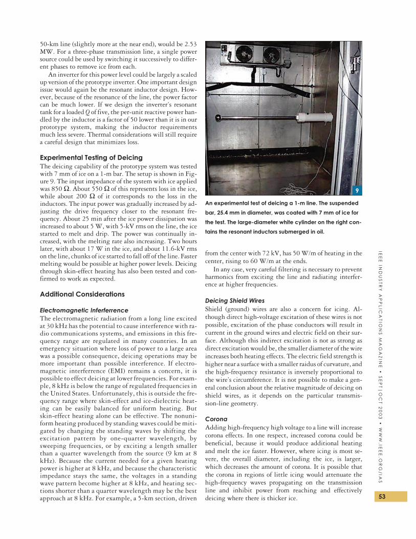
Experimental Testing of DeicingThe deicing capability of the prototype system was testedwith 7 mm of ice on a 1-m bar. The setup is shown in Fig-ure 9. The input impedance of the system with ice appliedwas 850 Ω. About 550 Ω of this represents loss in the ice,while about 200 Ω of it corresponds to the loss in theinductors. The input power was gradually increased by ad-justing the drive frequency closer to the resonant fre-quency. About 25 min after the ice power dissipation wasincreased to about 5 W, with 5-kV rms on the line, the icestarted to melt and drip. The power was continually in-creased, with the melting rate also increasing. Two hourslater, with about 17 W in the ice, and about 11.6-kV rmson the line, chunks of ice started to fall off of the line. Fastermelting would be possible at higher power levels. Deicingthrough skin-effect heating has also been tested and con-firmed to work as expected.
Additional Considerations
Electromagnetic InferferrenceThe electromagnetic radiation from a long line excitedat 30 kHz has the potential to cause interference with ra-dio communications systems, and emissions in this fre-quency range are regulated in many countries. In anemergency situation where loss of power to a large areawas a possible consequence, deicing operations may bemore important than possible interference. If electro-magnetic interferrence (EMI) remains a concern, it ispossible to effect deicing at lower frequencies. For exam-ple, 8 kHz is below the range of regulated frequencies inthe United States. Unfortunately, this is outside the fre-quency range where skin-effect and ice-dielectric heat-ing can be easily balanced for uniform heating. Butskin-effect heating alone can be effective. The nonuni-form heating produced by standing waves could be miti-gated by changing the standing waves by shifting theexcitation pattern by one-quarter wavelength, bysweeping frequencies, or by exciting a length smallerthan a quarter wavelength from the source (9 km at 8kHz). Because the current needed for a given heatingpower is higher at 8 kHz, and because the characteristicimpedance stays the same, the voltages in a standingwave pattern become higher at 8 kHz, and heating sec-tions shorter than a quarter wavelength may be the bestapproach at 8 kHz. For example, a 5-km section, driven
from the center with 72 kV, has 50 W/m of heating in thecenter, rising to 60 W/m at the ends.
In any case, very careful filtering is necessary to preventharmonics from exciting the line and radiating interfer-ence at higher frequencies.
Deicing Shield WiresShield (ground) wires are also a concern for icing. Al-though direct high-voltage excitation of these wires is notpossible, excitation of the phase conductors will result incurrent in the ground wires and electric field on their sur-face. Although this indirect excitation is not as strong asdirect excitation would be, the smaller diameter of the wireincreases both heating effects. The electric field strength ishigher near a surface with a smaller raidus of curvature, andthe high-frequency resistance is inversely proportional tothe wire’s circumference. It is not possible to make a gen-eral conclusion about the relative magnitude of deicing onshield wires, as it depends on the particular transmis-sion-line geometry.
CoronaAdding high-frequency high voltage to a line will increasecorona effects. In one respect, increased corona could bebeneficial, because it would produce additional heatingand melt the ice faster. However, where icing is most se-vere, the overall diameter, including the ice, is larger,which decreases the amount of corona. It is possible thatthe corona in regions of little icing would attenuate thehigh-frequency waves propagating on the transmissionline and inhibit power from reaching and effectivelydeicing where there is thicker ice. 53
IEE
EIN
DU
ST
RY
AP
PL
ICA
TIO
NS
MA
GA
ZIN
E•
SE
PT
|O
CT
20
03
•W
WW
.IEE
E.O
RG
/IA
S
An experimental test of deicing a 1-m line. The suspended
bar, 25.4 mm in diameter, was coated with 7 mm of ice for
the test. The large-diameter white cylinder on the right con-
tains the resonant inductors submerged in oil.
9

To reduce corona, the waveform could be modulated, asshown in Figure 10, to reduce the high-frequency ampli-tude as the peaks in the low-frequency voltage are ap-proached. Modulation could be used to achieve a waveformwith constant peak voltage. In Figure 10, the high-fre-quency peaks are higher than the low-frequency peaks.This is because the low-freequency excitation isthree-phase, whereas the high-freqeucny excitation is ap-plied to only one conductor, which allows it to have ahigher peak voltage for the same peak field strength.
Another strategy is to increase the frequency, which in-creases both skin-effect and dielectric losses for a given exci-tation voltage, thus allowing lower voltage for the sameheating requirement. Dielectric loss tends to increase fasterwith frequency, leading to poorer matching between thetwo heating effects. However, this may not be a problem:the ice in the regions of high dielectric loss (voltageantinodes) will melt first, even with low excitation. Then,the excitation level can be increased to melt the remainingice through skin-effect loss. For example, at 145 kHz, 50 kVis sufficient to heat 15 mm ice with 50 W/m at the voltageantinodes, but at the current antinodes, the heating is onlyabout 22 W/m, which won’t melt the ice as fast. However,increasing the voltage to 75 kV will produce 50 W/m at thecurrent antinodes and higher heating at the voltageanitnodes, but only if ice remains on them.
ConclusionThe application of high-frequency electric fields to melt-ing ice on power transmission lines appears promising.
Combined dielectric heating and skin-ef-fect heating can be used to achieve uniformheating despite standing-wave patterns.For both small-scale prototypes andfull-scale systems, the critical componentis the resonant inductor. Winding shapeoptimization techniques allow achievinglow loss in this component despite thehigh ac current in it. Tests on a 1-m linedemonstrated effective deicing, even withrelatively low power applied.
AcknowledgmentThis work was supported by the New YorkPower Authority, CEA Technologies Inc.,and Ice Engineering LLC.
References[1] V.F. Petrenko and C.R. Sullivan, “Methods and sys-
tems for removing ice from surfaces,” U.S. PatentApplication PCT/US99/28330, 1999.
[2] J.D. McCurdy, C.R. Sullivan, and V.F. Petrenko,“Using dielectric losses to de-ice power transmis-sion lines with 100 khz high-voltage excitation,” inConf. Rec. IEEE Industry Applications Society Annu.
Meeting, 2001, pp. 2515-2519.[3] V.F. Petrenko and R.W. Whitworth, Physics of Ice.
London, U.K.: Oxford Univ. Press, 1999.[4] J. Hu and C.R. Sullivan, “Optimization of shapes for
round-wire high-frequency gapped-inductorwindings,” in Conf. Rec. IEEE Industry Applications
Society Annu. Meeting, 1998, pp. 900-906.[5] J. Hu and C.R. Sullivan, “Analytical method for generalization of
numerically optimized inductor winding shapes,” in IEEE Power
Electronics Specialists Conf. Rec., 1999, vol. 1, pp. 568-573.
[6] C.R. Sullivan, J.D. McCurdy, and R.A. Jensen, “Analysis of minimum
cost in shape-optimized litz-wire inductor windings,” in IEEE Power
Electronics Specialists Conf. Rec., 2001, vol. 3, pp. 1473-1478.
[7] R. Jensen and C.R. Sullivan, “Optimal core dimensional ratios for mini-
mizing winding loss in high-frequency gapped-inductor windings,”
in Proc. IEEE Applied Power Electronics Conf., 2003, pp. 1164-1169.
[8] W.M. Chew and P.D. Evans, “High frequency inductor design con-
cepts,” in IEEE Power Electronics Specialists Conf. Rec., 1991, vol.
22, pp. 673-678.
[9] K.D.T. Ngo and M.H. Kuo, “Effects of air gaps on winding loss in
high-frequency planar magnetics,” in IEEE Power Electronics Spe-
cialists Conf. Rec., 1988, vol. 2, pp. 1112-1119.
[10] N.H. Kutkut and D.M. Divan, “Optimal air-gap design in high-fre-
quency foil windings,” IEEE Trans. Power Electron., vol. 13, pp.
942-949, Sept. 1998.
[11] J. Hu and C.R. Sullivan, “The quasi-distributed gap technique for
planar inductors: Design guidelines,” in Conf. Rec. IEEE Industry
Applications Society Annu. Meeting, 1997, pp. 1147-1152.
Charles R. Sullivan ([email protected]),Victor F. Petrenko, Joshua D. McCurdy, and Valeri Kozlioukare with Dartmouth College in Hanover, New Hampshire, USA.This article first appeared in its original form at the 2001 IEEEIAS Annual Meeting.54
IEE
EIN
DU
ST
RY
AP
PL
ICA
TIO
NS
MA
GA
ZIN
E•
SE
PT
|O
CT
20
03
•W
WW
.IE
EE
.OR
G/
IAS
The addition of a high-frequency waveform to a 133-kV rms, 60-Hz
phase-to-ground voltage with no increase in peak voltage. The modulation
of the high-frequency waveform keeps the peak field at the surface of the
conductor from exceeding that present with only the low-frequency,
three-phase excitation. The high-frequency peak can be slightly higher
than the low-frequency peak because only a single phase is excited at
high frequency. For clarity, the high-frequency waveform shown here is at 2
kHz, much lower than the 8 kHz to 150 kHz that would be used in practice.
10