Breafly survey of -...
24
A Brief survey of AC Drive Fault Diagnosis & Detection by Petr Kadaník, Prague, December 1998 Contents: Preface I. Introduction II. Basics of AC Drives PWM Inverter AC Drive Semiconductor Technologies III. Faults in AC Drives AC Power Line Faults Frequency Converter Faults Failure Mechanisms in Power Electronic Components AC Motor Faults IV. Protection of AC Drives Conventional Protection Scheme for VSI AC Drives Standard Industrial AC Drive Protection V. Faults Diagnosis & Detection Methods Expert Knowledge-based Systems On-line Condition Monitoring AC Motor Diagnosis Literature
Transcript of Breafly survey of -...
A Brief survey of
AC Drive Fault Diagnosis & Detection
by Petr Kadaník, Prague, December 1998
Contents:PrefaceI. IntroductionII. Basics of AC Drives
PWM Inverter AC DriveSemiconductor Technologies
III. Faults in AC DrivesAC Power Line FaultsFrequency Converter FaultsFailure Mechanisms in Power Electronic ComponentsAC Motor Faults
IV. Protection of AC DrivesConventional Protection Scheme for VSI AC DrivesStandard Industrial AC Drive Protection
V. Faults Diagnosis & Detection MethodsExpert Knowledge-based SystemsOn-line Condition MonitoringAC Motor Diagnosis
Literature
A Brief survey of AC Drive Fault Diagnosis & Detection page 2
PrefaceThis text represents an attempt at a brief report about the present state ofevolution of the AC drive fault diagnosis and fault detection. Mostlyconference papers, but also journal articles, web pages and productspecifications were used to summarize all available pieces of informationabout this technical area.All the fault diagnosis approaches are presented with a view to a voltage-source inverter AC drive, because of the largest using of this type in theindustry.Text is organized as follows. Some background is given in chapter I.Section II briefly reviews AC drive’s main features and topology.Classification of AC drive faults is given in chapter III and a protection ofstandard AC drives is described in chapter IV. The last chapter contentsdiagnosis methods with some examples of diagnostic applications.
Prague, December 1998 page 3
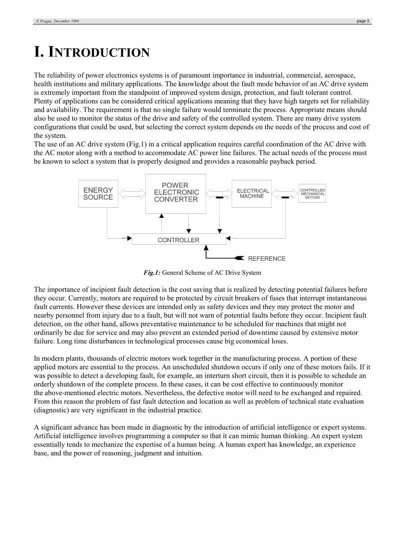
I. INTRODUCTIONThe reliability of power electronics systems is of paramount importance in industrial, commercial, aerospace,health institutions and military applications. The knowledge about the fault mode behavior of an AC drive systemis extremely important from the standpoint of improved system design, protection, and fault tolerant control.Plenty of applications can be considered critical applications meaning that they have high targets set for reliabilityand availability. The requirement is that no single failure would terminate the process. Appropriate means shouldalso be used to monitor the status of the drive and safety of the controlled system. There are many drive systemconfigurations that could be used, but selecting the correct system depends on the needs of the process and cost ofthe system.The use of an AC drive system (Fig.1) in a critical application requires careful coordination of the AC drive withthe AC motor along with a method to accommodate AC power line failures. The actual needs of the process mustbe known to select a system that is properly designed and provides a reasonable payback period.
Fig.1: General Scheme of AC Drive System
The importance of incipient fault detection is the cost saving that is realized by detecting potential failures beforethey occur. Currently, motors are required to be protected by circuit breakers of fuses that interrupt instantaneousfault currents. However these devices are intended only as safety devices and they may protect the motor andnearby personnel from injury due to a fault, but will not warn of potential faults before they occur. Incipient faultdetection, on the other hand, allows preventative maintenance to be scheduled for machines that might notordinarily be due for service and may also prevent an extended period of downtime caused by extensive motorfailure. Long time disturbances in technological processes cause big economical loses.
In modern plants, thousands of electric motors work together in the manufacturing process. A portion of theseapplied motors are essential to the process. An unscheduled shutdown occurs if only one of these motors fails. If itwas possible to detect a developing fault, for example, an interturn short circuit, then it is possible to schedule anorderly shutdown of the complete process. In these cases, it can be cost effective to continuously monitorthe above-mentioned electric motors. Nevertheless, the defective motor will need to be exchanged and repaired.From this reason the problem of fast fault detection and location as well as problem of technical state evaluation(diagnostic) are very significant in the industrial practice.
A significant advance has been made in diagnostic by the introduction of artificial intelligence or expert systems.Artificial intelligence involves programming a computer so that it can mimic human thinking. An expert systemessentially tends to mechanize the expertise of a human being. A human expert has knowledge, an experiencebase, and the power of reasoning, judgment and intuition.

A Brief survey of AC Drive Fault Diagnosis & Detection page 4
II. BASICS OF AC DRIVESAC drives are being designed into a more demanding group of applications. Originally, the applications weremostly limited to fans and pumps where the energy savings provided all immediate payback for the premiumcharged. Over the years, the cost of AC drive systems has been decreasing and their performance increasing. ACdrives are being applied to overhead cranes, continuous casters, winders, unwinders, extruders and other moredemanding applications.The AC machines, especially the cage-type induction motors (IMs), seem to process several distinct virtues incomparison with DC machines. These relate to lower cost and weight, lower inertia, higher efficiency, improvedruggedness and the capability to operate in a dirty and explosive environment due to the absence of commutatorsand brushes.The speed of an AC machine is related to stator supply frequency which produces the synchronously rotatingmagnetic field. If frequency is increased to increase speed of the machine, the magnitude of air-gap flux isreduced due to increased magnetizing reactance, and correspondingly the developed torque is reduced. For thisreason, an AC machine normally requires variable-voltage variable-frequency power supply for speed control.
There are two basic forms of power electronic converters for changing from the fixed AC line frequency tovariable motor frequency: cyclo-converter (performs this operation in a single conversion stage) and converterswith a DC-link (converter is decoupled into the two sides, Fig.2).The cycloconverter drives are used only in very large horse-power applications. The cost and complexity of powerand control circuits make them uncompetitive with other classes of drives in general applications.
Fig.2: Simplified diagram of a frequency converter
The process of converting DC to AC power is called inversion and it is the inverter which creates the variablefrequency from the DC source which is used to drive an IM at a variable speed. In general, two basic types ofinverters exist which are totally different in their behavior. The so called Voltage-Stiff (or Source) Inverterabbreviated as VSI is more common and this type of inverter creates relatively well defined switched voltagewaveform at the terminals of the motor. The DC bus is maintained as voltage stiff by the use of a large capacitorin the DC link. A voltage source inverter differs from the voltage stiff inverter in that the DC link is establishedwith a DC source (battery for instance). The resulting motor current is then governed primarily by the motor loadand the speed. The VSI is also termed a voltage source inverter. However, it is clear that the DC link itself is trulynot a power source if the link voltage is supported only by an energy storage element such as a DC capacitor. TheVSI is typically subdivided into two forms the so called six step inverter and the pulse width modulated (PWM)inverter.The second type of inverter, the Current Stiff (or Source) Inverter (CSI) provides a switched current waveform atthe motor terminals. The DC bus is maintained as current stiff by use of a large inductor in the DC link. Thevoltage waveform is now governed primarily by the motor load and speed.
Prague, December 1998 page 5
PWM Inverter AC Drive
PWM inverter-fed induction motor drives are being used in greater numbers throughout a wide variety ofindustrial and commercial applications. The advantages are numerous, and may shortly be summed up asimproved process control, which among other things leads to energy saving, and less inrush currents and torquepulsations during the starting period which gives a longer life for pumps and other mechanical equipment, greaterreliability and performance. PWM inverter-fed motors are usually more reliable than those supplied directly on-line. For instance, the problem of broken rotor bars, mainly due to excessive starting torque, is practically avoidedby means of soft starting with an inverter.Motor operation above base speed should be verified with the motor manufacturer. PWM inverters can outputfrequencies up to 400 hertz in many cases. However, the motor's mechanical design, in terms of bearings andbalancing, limits the maximum frequency on which it can be operated. The power supplied to the motor by aPWM inverter has some adverse effects too (increased heating, high peak voltages, and increased audible noise).Most industrial applications in the power range from fractional horsepower up to some hundred kilowatts makeuse of Voltage Source Inverter (VSI) type converters.
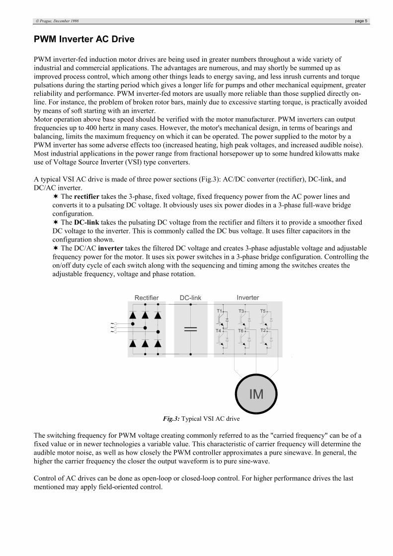
A typical VSI AC drive is made of three power sections (Fig.3): AC/DC converter (rectifier), DC-link, andDC/AC inverter.
The rectifier takes the 3-phase, fixed voltage, fixed frequency power from the AC power lines andconverts it to a pulsating DC voltage. It obviously uses six power diodes in a 3-phase full-wave bridgeconfiguration.
The DC-link takes the pulsating DC voltage from the rectifier and filters it to provide a smoother fixedDC voltage to the inverter. This is commonly called the DC bus voltage. It uses filter capacitors in theconfiguration shown.
The DC/AC inverter takes the filtered DC voltage and creates 3-phase adjustable voltage and adjustablefrequency power for the motor. It uses six power switches in a 3-phase bridge configuration. Controlling theon/off duty cycle of each switch along with the sequencing and timing among the switches creates theadjustable frequency, voltage and phase rotation.
Fig.3: Typical VSI AC drive
The switching frequency for PWM voltage creating commonly referred to as the "carried frequency" can be of afixed value or in newer technologies a variable value. This characteristic of carrier frequency will determine theaudible motor noise, as well as how closely the PWM controller approximates a pure sinewave. In general, thehigher the carrier frequency the closer the output waveform is to pure sine-wave.
Control of AC drives can be done as open-loop or closed-loop control. For higher performance drives the lastmentioned may apply field-oriented control.
A Brief survey of AC Drive Fault Diagnosis & Detection page 6
Semiconductor Technologies
Today's PWM inverters employ a several types of semiconductor devices in the inverter. These are:• Thyristors plus External Commutation Network• Bipolar Junction Transistors (BJTs)• MOS Field Effect Transistors (MOSFETs)• Insulated Gate Bipolar Transistors (IGBTs)• Gate Turn-off Thyristors (GTOs)• MOS Controlled Thyristors (MCTs)
Depending on power, current, frequency and voltage, suitable type has to be applied.
The IGBT transistor is a combination of the BJT and the MOSFETs. It has the MOSFET’s desired features on theinput and the BJT’s best features on the output. The IGBT are well suited for VSI AC drives. The primarybenefits are the power range, the good conductive features, the high switching frequency and the simple control.
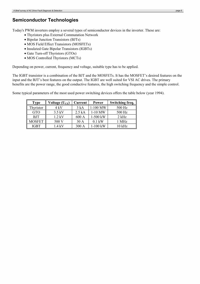
Some typical parameters of the most used power switching devices offers the table below (year 1994).
Type Voltage (UCE) Current Power Switching freq.Thyristor 4 kV 3 kA 1-100 MW 500 Hz
GTO 3.5 kV 2.5 kA 1-10 MW 500 HzBJT 1.2 kV 600 A 1-500 kW 2 kHz
MOSFET 500 V 30 A 0.1 kW 1 MHzIGBT 1.4 kV 300 A 1-100 kW 10 kHz
Prague, December 1998 page 7
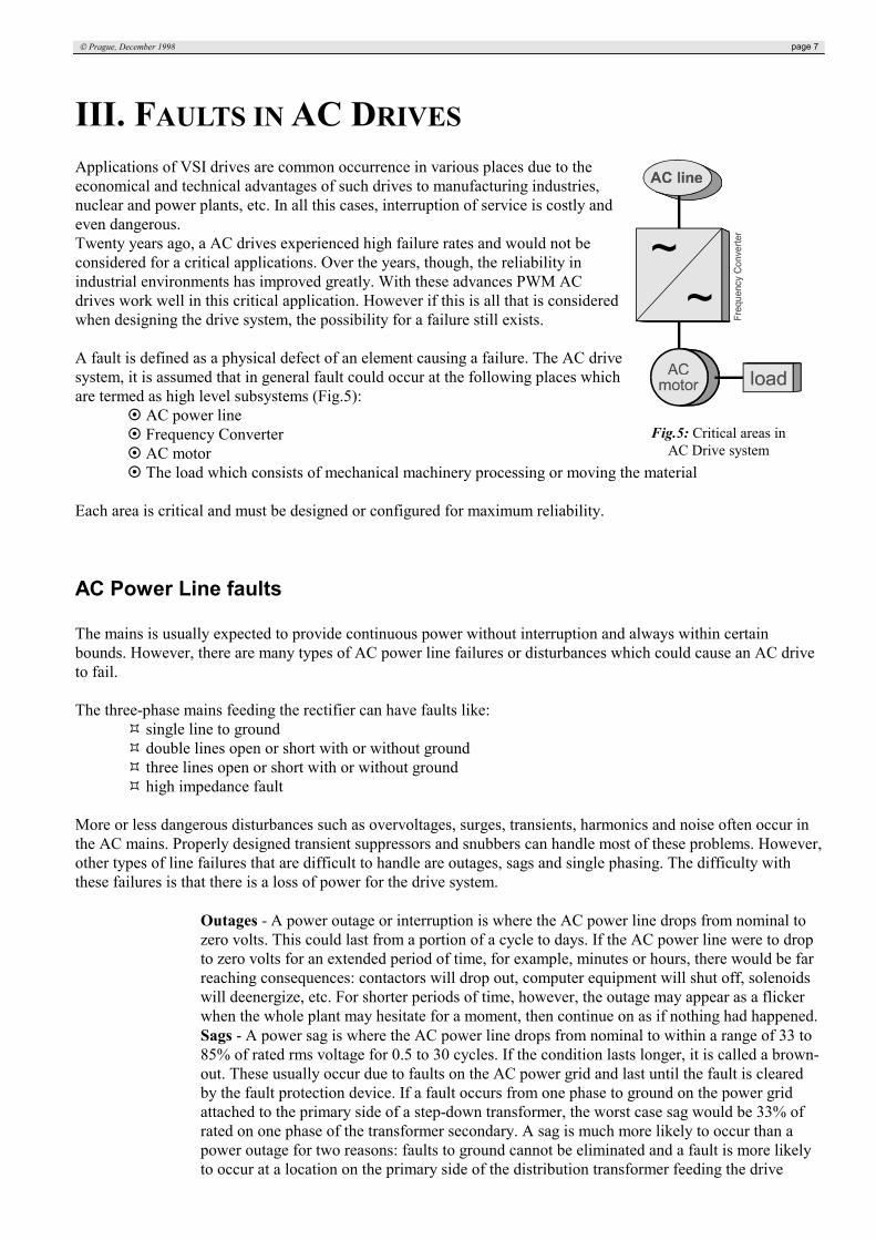
III. FAULTS IN AC DRIVESApplications of VSI drives are common occurrence in various places due to theeconomical and technical advantages of such drives to manufacturing industries,nuclear and power plants, etc. In all this cases, interruption of service is costly andeven dangerous.Twenty years ago, a AC drives experienced high failure rates and would not beconsidered for a critical applications. Over the years, though, the reliability inindustrial environments has improved greatly. With these advances PWM ACdrives work well in this critical application. However if this is all that is consideredwhen designing the drive system, the possibility for a failure still exists.
A fault is defined as a physical defect of an element causing a failure. The AC drivesystem, it is assumed that in general fault could occur at the following places whichare termed as high level subsystems (Fig.5):
AC power line Frequency Converter AC motor The load which consists of mechanical machinery processing or moving the material
Each area is critical and must be designed or configured for maximum reliability.
AC Power Line faults
The mains is usually expected to provide continuous power without interruption and always within certainbounds. However, there are many types of AC power line failures or disturbances which could cause an AC driveto fail.
The three-phase mains feeding the rectifier can have faults like: single line to ground double lines open or short with or without ground three lines open or short with or without ground high impedance fault
More or less dangerous disturbances such as overvoltages, surges, transients, harmonics and noise often occur inthe AC mains. Properly designed transient suppressors and snubbers can handle most of these problems. However,other types of line failures that are difficult to handle are outages, sags and single phasing. The difficulty withthese failures is that there is a loss of power for the drive system.
Outages - A power outage or interruption is where the AC power line drops from nominal tozero volts. This could last from a portion of a cycle to days. If the AC power line were to dropto zero volts for an extended period of time, for example, minutes or hours, there would be farreaching consequences: contactors will drop out, computer equipment will shut off, solenoidswill deenergize, etc. For shorter periods of time, however, the outage may appear as a flickerwhen the whole plant may hesitate for a moment, then continue on as if nothing had happened.Sags - A power sag is where the AC power line drops from nominal to within a range of 33 to85% of rated rms voltage for 0.5 to 30 cycles. If the condition lasts longer, it is called a brown-out. These usually occur due to faults on the AC power grid and last until the fault is clearedby the fault protection device. If a fault occurs from one phase to ground on the power gridattached to the primary side of a step-down transformer, the worst case sag would be 33% ofrated on one phase of the transformer secondary. A sag is much more likely to occur than apower outage for two reasons: faults to ground cannot be eliminated and a fault is more likelyto occur at a location on the primary side of the distribution transformer feeding the drive
Fig.5: Critical areas inAC Drive system
A Brief survey of AC Drive Fault Diagnosis & Detection page 8
system since more equipment is located there.Single phasing- A single phasing power failure can only occur on 3-phase systems where oneof the three phases drops below 50% of nominal. This is also due to a fault located on thepower grid. There could also be a 10% drop in voltage between the other two phases at thesame time.
There are many configurations available which help reduce the susceptibility of the drive system to power linefailures. The proper selection is again based on system requirements and cost.
Frequency Converter Faults
Faults that led to failures have been categorized as follows for the frequency converter:• faults on the power part of the converter (transistor or diode failures)• base drive faults• faults on control circuits• power faults• faults on external auxiliaries• improper use of the converter
Switching device failure may be caused by an inadequate gate drive or control signal, or due to excessive thermalstress. Whilst a single device failure happens in most cases, two devices being faulty at the same instant can occuroccasionally. Diode failure causes high current stress on the DC input of the inverter. This fault can occur ineither the upper or lower leg of one of the three phases. On rare occasions two diodes of different legs may befaulty simultaneously.
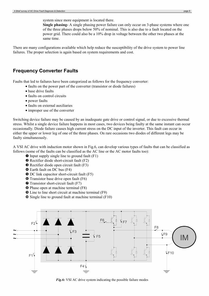
A VSI AC drive with induction motor shown in Fig.6, can develop various types of faults that can be classified asfollows (some of the faults can be classified as the AC line or the AC motor faults too):
Input supply single line to ground fault (F1) Rectifier diode short-circuit fault (F2) Rectifier diode open circuit fault (F3) Earth fault on DC bus (F4) DC link capacitor short-circuit fault (F5) Transistor base drive open fault (F6) Transistor short-circuit fault (F7) Phase open at machine terminal (F8) Line to line short circuit at machine terminal (F9) Single line to ground fault at machine terminal (F10)
Fig.6: VSI AC drive system indicating the possible failure modes

Prague, December 1998 page 9
Failure Mechanisms in Power Electronic Components
Most power inverter circuits operate in an environment requiring rapid speed variation, frequent stop/starting andconstant overloading. The circuits, particularly semiconductor switching devices, are subject to constant abuse ofover-current surge and voltage overswing. Although protection devices such as snubber circuits are commonlyused to alleviate the stresses involved, the possibility of incipient faults such as switch failure or a diode shorting-through is inherent in a power inverter circuit. Such faults may not cause near-instant catastrophe but willcertainly affect the performance of the drive system.
Faults in the converter may origin from faulty components, and this again can be a result of faults in the coolingsystem or use of improper components.As known, it's possible to individuate two different categories of failure mechanisms for electronic components.The first category include failure mechanisms related to electrical overstress (EOS). In this case device is drivenof the Safe Operating Area (SOAR) and usually the overstresses are the direct cause of immediate changes in thestructure of a device resulting in a catastrophic fault.The other category of failures are related to the intrinsic aspect of a component and can be seen as a fatigue effect.For example, it is known that, due to the current flows in the internal structure of a device, it is possible a changeof the structure properties and failures can occur even if the device is working within its SOAR.
The following two tables summarize the main failure mechanisms for power semiconductor devices with therelated stressors. Table 1 reports the failures due to electrical overstress, table 2 the long-term failures.
Failure Mechanism StressorCurrent Breakdown Current Density
Environmental TemperatureThermal Cracks Dissipated Power
Environmental TemperatureHigh-Voltage Breakdown Electric Field
Environmental TemperatureSwitch-on Effect (diode) Re-polarisation Speed (du/dt)
Speed of Charging (di/dt)Switch-off Effect (diode) Stored Charges
Re-pol. Speed (du/dt)Maximum Reverse CurrentApplied Reverse Voltage
Forward bias Second Breakdown (BJT) UCESlope of the Base Current During Switch-on (dib/dt )Slope of the Collector Current During Switch-on (dic/dt)Environmental Temperature
Reverse bias Second Breakdown (BJT) UCEStored Charge in the Transistor Collector During Switch-offDischarge Speed (dib/dt )Environmental Temperature
Tab.1: Power electronic component failures due to electrical overstress
Failure Mechanism StressorCorrosion:A device encapsulated in a non-hermetic package presents corrosionproblems. Due to corrosion metallization patterns can open. Althoughdependent on time, it is an hard job to give a formula of time dependency ofcorrosion.
Moisture
Electromigration: Current Density
A Brief survey of AC Drive Fault Diagnosis & Detection page 10
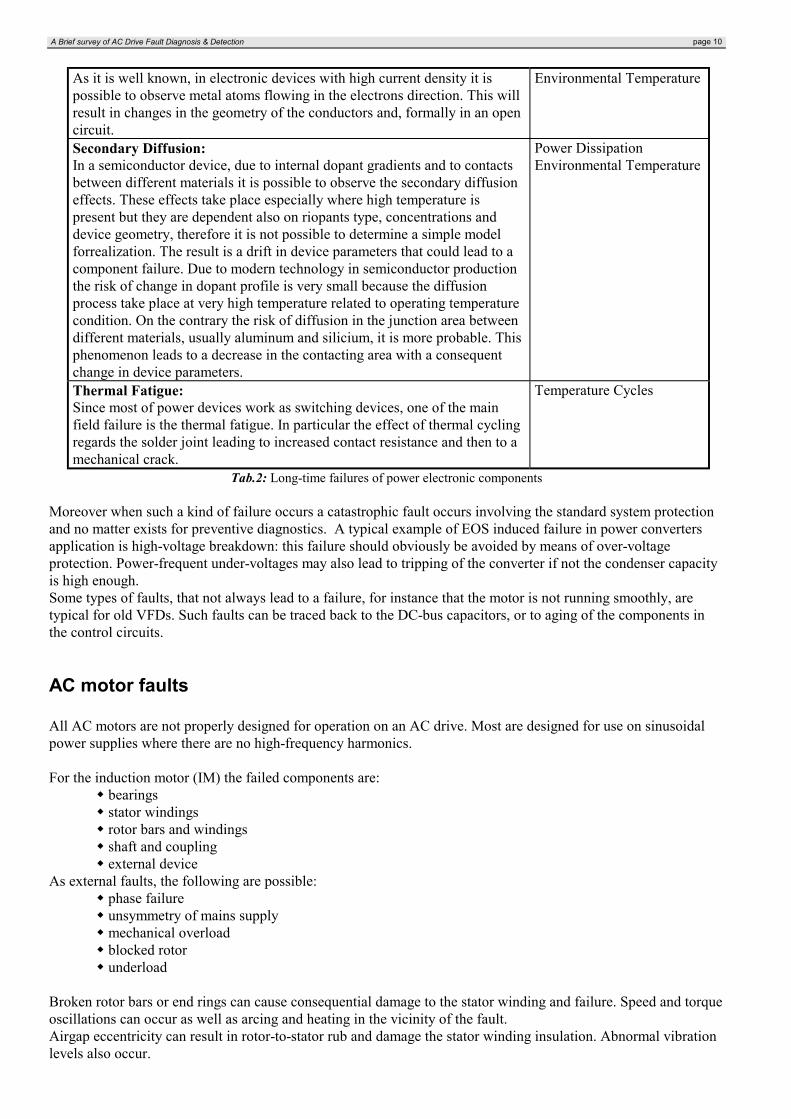
As it is well known, in electronic devices with high current density it ispossible to observe metal atoms flowing in the electrons direction. This willresult in changes in the geometry of the conductors and, formally in an opencircuit.
Environmental Temperature
Secondary Diffusion:In a semiconductor device, due to internal dopant gradients and to contactsbetween different materials it is possible to observe the secondary diffusioneffects. These effects take place especially where high temperature ispresent but they are dependent also on riopants type, concentrations anddevice geometry, therefore it is not possible to determine a simple modelforrealization. The result is a drift in device parameters that could lead to acomponent failure. Due to modern technology in semiconductor productionthe risk of change in dopant profile is very small because the diffusionprocess take place at very high temperature related to operating temperaturecondition. On the contrary the risk of diffusion in the junction area betweendifferent materials, usually aluminum and silicium, it is more probable. Thisphenomenon leads to a decrease in the contacting area with a consequentchange in device parameters.
Power DissipationEnvironmental Temperature
Thermal Fatigue:Since most of power devices work as switching devices, one of the mainfield failure is the thermal fatigue. In particular the effect of thermal cyclingregards the solder joint leading to increased contact resistance and then to amechanical crack.
Temperature Cycles
Tab.2: Long-time failures of power electronic components
Moreover when such a kind of failure occurs a catastrophic fault occurs involving the standard system protectionand no matter exists for preventive diagnostics. A typical example of EOS induced failure in power convertersapplication is high-voltage breakdown: this failure should obviously be avoided by means of over-voltageprotection. Power-frequent under-voltages may also lead to tripping of the converter if not the condenser capacityis high enough.Some types of faults, that not always lead to a failure, for instance that the motor is not running smoothly, aretypical for old VFDs. Such faults can be traced back to the DC-bus capacitors, or to aging of the components inthe control circuits.
AC motor faults
All AC motors are not properly designed for operation on an AC drive. Most are designed for use on sinusoidalpower supplies where there are no high-frequency harmonics.
For the induction motor (IM) the failed components are: bearings stator windings rotor bars and windings shaft and coupling external device
As external faults, the following are possible: phase failure unsymmetry of mains supply mechanical overload blocked rotor underload
Broken rotor bars or end rings can cause consequential damage to the stator winding and failure. Speed and torqueoscillations can occur as well as arcing and heating in the vicinity of the fault.Airgap eccentricity can result in rotor-to-stator rub and damage the stator winding insulation. Abnormal vibrationlevels also occur.
Prague, December 1998 page 11
Worn or damaged ball bearings, mechanical misalignment, abnormal rotor unbalance and eccentricity, shaft whirland resonant torsional vibration are typical mechanical malfunctions.Insulation degradation due to aging, contamination, voltage surges or abnormal vibration can lead to insulationbreakdown and failure.
Insulation breakdown usually accounts for between one-third to one-half of all motor failures. The insulationwhich is most likely to fail is the turn insulation, because it is thin yet must withstand voltage spikes, long termaging, thermal cycling and mechanical vibration.
Some common machine faults caused by winding insulation failure due to excessive voltage or current stress arepractically eliminated when inverter power supply is used. This is because the line voltage surges are absorbed atthe converter input, and inverter overcurrent protection limits the machine current. The problem of broken rotorbars mainly due to direct on-line start is practically eliminated by soft starting with an inverter. For these reasons,machine faults are not deeply considered in this text.
The encoder is an item usually associated with the motor and may have a failure rate higher than the motor.A shutdown due to a failure in the encoder can be prevented by allowing the drive to switch from a speedcontrol to a frequency control mode of operation with a smooth transition. Another method used tominimize downtime due to an encoder failure is to use encoders with two sets of output channels. When oneset fails, the connector can easily be moved to the second output set of channels.
Even though the AC motor is reliable and extremely robust, the most common cause of motor failure, when usedwith an AC drive, is overheating.Overheating can be the result of any or all of the following conditions:
• Operating at high torques and low speed, the efficiency of the internal fan drops off with the square of thespeed. Thus, it cannot cool the motor as well at lower speeds. The maximum torque available at differentspeeds maintaining the maximum allowable motor temperature, can vary greatly from motor to motor andfrom drive type to drive type. The AC motor usually needs to be derated.• The AC drive creates harmonics in the motor current causing extra heating in the copper conductors andthe iron due to additional eddy currents. This requires additional derating for the motor.• High-frequency harmonics in the motor current can cause large amounts of heating in some types of rotorbars. The shape of the rotor bars has a primary effect on how well suited a particular AC motor is for use onan AC drive.
Voltage rise time depends on what components are used. The motor cable behaves as a transmission line for thesepulses, and at the motor there will be a reflection, depending on surge impedancies in motor and cable.Insulation failures are influenced by the following factors:
• RMS input voltage to inverter• rise time of inverter output voltage wave• cable length from inverter to motor• motor insulation, wire insulation and testing, stator winding design, impregnation etc.
The fault tree configuration of high and sub-level faults is shown in figure 7.

A Brief survey of AC Drive Fault Diagnosis & Detection page 12
Fig.7.: Fault tree configuration
Prague, December 1998 page 13
IV. PROTECTION OF AC DRIVESCurrent implementations of electric drive protection functions vary from electromechanical relays, staticelectronic relays, microprocessor-based relays and recently implemented microcontroller-based relays.There are two main reasons that make conventional relay protection inappropriate for heavy duty electric drives: itis insensible for operation in critical regimes and it is intolerant to short working disturbances. Also, withconventional relay protection the data about the momentary motor condition is unavailable. This can result in biglosses when switching off the motor, often greater than the value of the motor itself.The disadvantages of the conventional relay protection led to the development of electronic, microprocessor- andmicrocontroller-based protection. The advantages of the microcontroller-based protection are the integration ofmeasurement and protective functions, flexible selection of functional parameters, easy integration with asupervisory system, as well asadaptable and more precise technical characteristics with decreasing costs.
In general, the motor protection functions cover: current protection (short circuit, overcurrent) voltage protection (undervoltage, overvoltage, phase reversal, unsymmetric) grounding faults locked rotor protection (start-up and stall time monitoring) thermal protection (stator, rotor and bearing) motor system level protection
Usually, induction motors are protected by a motor protective circuit in the form of fuses with overload relays ormotor protection circuit breakers. All of these evaluate only the motor current. The traditional technique detectsonly a subset of the above-mentioned AC motor faults. A short circuit is detected by mechanical means, such as atripping device with a solenoid. Because of the high starting currents of modern motors, the tripping level is veryhigh, and the tripping device is not very sensitive to low-level short-circuit currents with high arcing resistances.To detect these faults, a phase-sensitive detection method, which is, however, rather complicated in realization, isdemand. Most other faults such as phase failure, blocked rotor, asymmetry of mains supply, interturn shortcircuits, and damaged fan impellers increases the motor temperature. In the traditional motor protection circuitbreaker, the bimetal release is a rough thermal model of the motor and detects these faults with a long time delay.
The direct measurement of motor temperature with sensors is more accurate. This method is used in large motorsor critical motor applications but at a very high cost due to sensor wiring or sensor cost.
State-of-the-art motor protection trip units are microprocessor based and are programmed with a precise thermalmodel of the motor.
For complete motor protection, vibrational techniques can also be used. With this, the stator, the rotor, and thebearings can be monitored. Finally, there are chemical methods for monitoring that analyze particles or gasesproduced by the electrical machine.
Conventional protection scheme for VSI AC drives
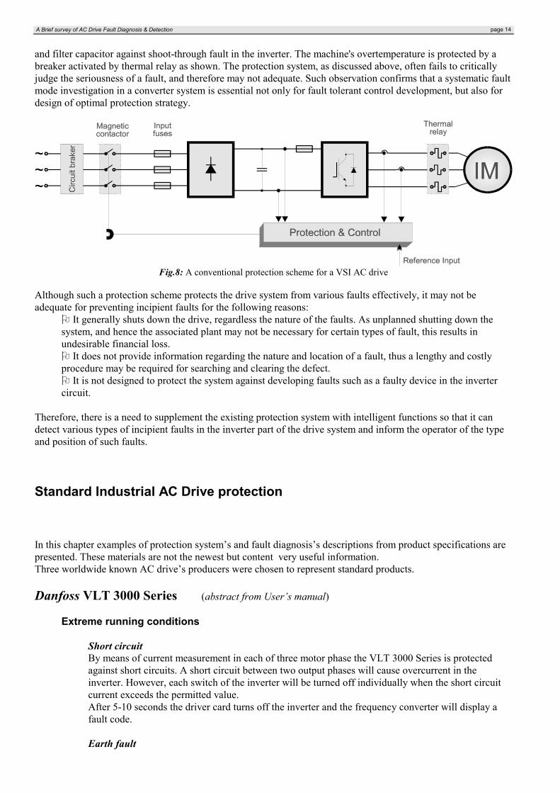
For a VSI AC system (Fig.3), the level of reliability is generally low. This is due to the use of power switchingdevices which are physically small and thermally fragile. The associated electronic control circuits are also proneto faults. The common method of improving the reliability is to design the system conservatively and for a safetycritical application a back-up circuit is usually provided.Fig.8 shows a typical protection system in a voltage-fed inverter drive. It includes protection against ground fault,DC link overvoltage/undervoltage, and inverter overcurrent. For one or more of such faults, the transistor basedrives are inhibited and the magnetic contactor at the input is opened. The input circuit breaker (CB) trips forsteady overcurrent to the converter. The input fuses blow for short-circuit fault of diode rectifier or DC linkcapacitor. Over/under voltage detectors monitor the DC link voltage. The inverter input fuse protects the rectifier
A Brief survey of AC Drive Fault Diagnosis & Detection page 14
and filter capacitor against shoot-through fault in the inverter. The machine's overtemperature is protected by abreaker activated by thermal relay as shown. The protection system, as discussed above, often fails to criticallyjudge the seriousness of a fault, and therefore may not adequate. Such observation confirms that a systematic faultmode investigation in a converter system is essential not only for fault tolerant control development, but also fordesign of optimal protection strategy.
Fig.8: A conventional protection scheme for a VSI AC drive
Although such a protection scheme protects the drive system from various faults effectively, it may not beadequate for preventing incipient faults for the following reasons:
It generally shuts down the drive, regardless the nature of the faults. As unplanned shutting down thesystem, and hence the associated plant may not be necessary for certain types of fault, this results inundesirable financial loss.
It does not provide information regarding the nature and location of a fault, thus a lengthy and costlyprocedure may be required for searching and clearing the defect.
It is not designed to protect the system against developing faults such as a faulty device in the invertercircuit.
Therefore, there is a need to supplement the existing protection system with intelligent functions so that it candetect various types of incipient faults in the inverter part of the drive system and inform the operator of the typeand position of such faults.
Standard Industrial AC Drive protection
In this chapter examples of protection system’s and fault diagnosis’s descriptions from product specifications arepresented. These materials are not the newest but content very useful information.Three worldwide known AC drive’s producers were chosen to represent standard products.
Danfoss VLT 3000 Series (abstract from User’s manual)
Extreme running conditions
Short circuitBy means of current measurement in each of three motor phase the VLT 3000 Series is protectedagainst short circuits. A short circuit between two output phases will cause overcurrent in theinverter. However, each switch of the inverter will be turned off individually when the short circuitcurrent exceeds the permitted value.After 5-10 seconds the driver card turns off the inverter and the frequency converter will display afault code.
Earth fault
Prague, December 1998 page 15
In case of an earth fault in a motor phase the inverter is turned off within 5-10 ms.
Motor-generated overvoltageThe voltage on the DC link can be increased when the motor acts as a generator. This takes place intwo cases:
1. The load runs the motor (at constant output frequency from the frequency converter), i.e. energy issupplied from the load
2. During deceleration (“ramp-down“), if the moment of inertia if high, the friction load is low and/orthe ramp-down time is short.The control attempts to correct the ramp if possible.The inverter turns off to protect the transistors and the DC bus capacitors when a certain DC voltagelevel is reached.
Mains drop-outDuring a mains drop-out the VLT frequency converter will continue to operate until the DC linkvoltage drops bellow minimum stop level. Typically 15% of rated mains supply voltage.
Fault messages
Inverter faultThe VLT power section is defectiveOvervoltageThe voltage of the VLT intermediate circuit is too high. Possible reason: line voltage too high,transients on the line voltage, or regenerative motor operation.UndervoltageThe voltage of the VLT intermediate circuit is too low. Possible reason: line voltage too low, ordefect in the VLT charging circuit/rectifier.OvercurrentThe peak current limit of the inverter has been reached. This may be due to short-circuit in the outputof the VLT frequency converter.• Check the motor a the motor cable for ground failureGround faultGround failure on the VLT output. Another reason might be that the motor cable is too long.• Consult the data sheets for permitted cable length. Check the motor and the motor cable for earthleakage.Over-tempThe temperature inside the VLT is too high. Possible reasons: the ambient temperature is too high(max.40/45 °C), the VLT cooling ribs are covered, or the VLT’s fan is defective.• Reduce the ambient temperature by increasing the ventilation. Uncover/clean the cooling ribs.Replace the fan.OverloadThe electronic VLT protection is active. This means that the motor has consumed more then 105% ofrated VLT current for too long.• Reduce the motor load. If this is not possible the application may require a large VLT frequencyconverter.Motor tripThe electronic motor protection is active. This means that the current consumed by the motor at lowspeed has been too high for too long.• The motor has been loaded excessively at low speed. If the load cannot be changed, you mustexchange the motor for a bigger one, or provide extra cooling of the existing motor.
ABB Frequency Converter ACD501 (abstract from User’s manual)
Fault indicationsSAMI GS (ABB control system) continuously monitors itself for faulty operation. If a faulty conditionshould arise, the SAMI GS will display a description of the fault trip and wait for the operator toacknowledge the fault before resuming operation.
A Brief survey of AC Drive Fault Diagnosis & Detection page 16
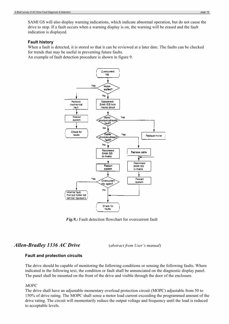
SAMI GS will also display warning indications, which indicate abnormal operation, but do not cause thedrive to stop. If a fault occurs when a warning display is on, the warning will be erased and the faultindication is displayed.
Fault historyWhen a fault is detected, it is stored so that it can be reviewed at a later date. The faults can be checkedfor trends that may be useful in preventing future faults.An example of fault detection procedure is shown in figure 9.
Fig.9.: Fault detection flowchart for overcurrent fault
Allen-Bradley 1336 AC Drive (abstract from User’s manual)
Fault and protection circuits
The drive should be capable of monitoring the following conditions or sensing the following faults. Whereindicated in the following text, the condition or fault shall be annunciated on the diagnostic display panel.The panel shall be mounted on the front of the drive and visible through the door of the enclosure.
MOPCThe drive shall have an adjustable momentary overload protection circuit (MOPC) adjustable from 50 to150% of drive rating. The MOPC shall sense a motor load current exceeding the programmed amount of thedrive rating. The circuit will momentarily reduce the output voltage and frequency until the load is reducedto acceptable levels.
Prague, December 1998 page 17
If the load is such that the motor is in a LOCKED ROTOR condition for more than 4 seconds, the drive willattempt to protect the motor and shut down on a MOPC fault.
Motor overload protectionThe drive shall provide motor overload protection when a single motor is connected to the drive. Theoverload protection shall be adjustable from 50 to 115% of the drive full load current rating.
Undervoltage sensingShould the input line fall below 10% of rated input voltage, the drive shall sense an undervoltage conditionand annunciate it on digital display panel.
Overvoltage sensingShould either the input line rive above 10% of rated input voltage, or the internal DC bus rise aboveallowable levels due to load regeneration.
Phase protectionThe drive shall have protection against (and indicate), a phase-to-phase short in the output load, or a shortcircuit in a phase of the output module. Each output phase shall be monitored. If a short circuit conditionoccurs, a circuit shall guard against further damage by turning off the entire output section experiencing theshorted condition.
Ground fault detectionShould an output phase short to earth ground occur, the drive shall have circuits to guard against excessivecurrents.
The drive protection functions shall monitor and annunciate the following conditions as a minimum:• overcurrent protection• short circuit protection• DC bus undervoltage protection• DC bus overvoltage protection• overtemperature protection• power semiconductor protection• ground fault protection
Drive diagnostics
The drive shall execute, on initial power-up, a self diagnostic check. The integral programming displaypanel shall provide first fault indication of drive protection functions. Fault indication shall be retained ifinput power is lost.
The microprocessor can store the status or value of vital parameters associated with each of the last N protectivetrips. These are an obvious service aid. Given access to such information, PC or other computerized supervisorysystem can act to achieve more comprehensive diagnosis providing a readout of the prescribed service procedureas well as detailed graphics to enhance the presentation. Such features are now included in specialized AC drivesbut could be standard on virtually any size of equipment.

A Brief survey of AC Drive Fault Diagnosis & Detection page 18
V. FAULTS DIAGNOSIS & DETECTION METHODSAdvanced indication of electric circuits unusual behavior, which may lead to catastrophic failures, is a veryattractive task. Obviously additional costs of a dedicated system devoted to monitoring and diagnostics areunacceptable. But for large power electronic drives and small, but safety-critical systems, condition monitoringhas been considered to be beneficial and important.
A commonly practiced method of improving reliability is to design the power circuit conservatively. Anothermethod is to have parallel redundant operation of components or circuits. Evidently, both these techniques areexpensive and can be justified only for high-reliability applications. As an alternative to the redundancytechnique, fault tolerant control has been proposed. The idea is to modify the drive control algorithm during afault in such a way that the faulty drive continuous to run in a degraded mode.
Two types of failure search strategies are described. These search strategies are called topographic search andsymptomatic search.
Topographic search uses the normal model of the system to select the next field of attention. Each field isthen judged to be good or bad through appropriate observation. The next field of attention can be either asubfield of the current field or a field of the same level that is logically or physically adjacent. Theadvantage of topographic search is its dependence upon the normal system operation rather than models ofmalfunction. However, the use of available information by topographic search is uneconomical becauseobservations are used only for good/bad judgments. Thus topographic search by itself may not lead todiagnosis.In symptomatic search, the diagnostician searches a library of symptom patterns to find a set thatmatches the observed symptoms. Then, the system state associated with the symptom pattern is identified.When there is ambiguity, more observations need to be collected to resolve it. The symptomatic search ismore complicated since systemdynamics and failure simulation are required and it needs more memory and memory management ascompared to topographic search.
A more powerful search technique can be designed by combining the above two search strategies in bothbackward and forward direction i.e. from observed symptoms to associated cause and from hypothesized causesto possible symptoms respectively.
There are possible the following typical ways of the detection, classification and location problems solution [8]:a) by the formulation of the deterministic and stochastic mathematical models for particular faultsb) by heuristic reasoning based on the expert systems and experiencec) by techniques based on artificial intelligence, specially neural networks and fuzzy logic
a)

Prague, December 1998 page 19
b) c)
Fig.10: Schematic diagrams of various methods for fault detection and diagnosisa) mathematical model based method, b) heuristic method, c) neural network based method
In Fig.10 the schematic diagrams of mentioned above fault detection methods are presented.The diagnostic systems based on mathematical models usually require a good knowledge of the physicalphenomena of the plant and lead to very complicated software. The heuristic reasoning require the expert presenceto perform any diagnostic task. Besides these two ways are very much dependent on mathematical modelsadequacy, measurement errors and expert knowledge.The connection of the knowledge based on analytical mathematical models and heuristic knowledge, which isrealized in the expert systems, enables the obtaining of significantly greater diagnostic efficiency.The main idea of these methods consist in the fault determination on the base of comparison of the mathematicalmodels analysis and the expert knowledge about the operation states of the plant.The intensive research are performed recently in the field of neural networks application to the drive systemdiagnosis, as neural fault detectors and classifiers. They are specially used for fault detection in the main elementof the drive - in the electrical machine.
A VSI AC drive is mainly an electrical installation except the driven load whose contribution to the VSI fault listis minimal. This is due to the marked difference of time constant between the electrical and mechanical systems.In the case of a mechanical fault, the motor can be disconnected from the VSI system before a serious damage hasoccurred.To avoid expensive additions to existing circuits or to well-integrated designs, monitoring of only input andoutput currents and voltages is often preferable.
There are two aspects of fault diagnosis methods [16]:• on-line monitoring and real-time fault diagnosis• off-line troubleshooting diagnosis and operator training
The on-line monitoring will be discussed later.When service interruption is tolerated or redundancy is available, off-line troubleshooting is a commonphenomenon in diagnosis and repair of electromechanical devices. The use of expert systems in this area canfacilitate and speed up the troubleshooting and repair or replace process. The knowledge programmed in theexpert system is ready to be consulted to assist in the diagnosis process. The other major application of thesesystems is in assisting operator training. The other advantage of expert systems in this area is that the knowledgein the expert system can be easily updated to cope up with new innovations.
Expert Knowledge-based system
An experienced engineer can detect and diagnose the circuit faults by checking the voltage/currentmeasurements and operating performance of the drive system. However, not only are such experts expensive andscarce, they cannot perform continuous on-line monitoring of the system. The knowledge base of the expert

A Brief survey of AC Drive Fault Diagnosis & Detection page 20
system consists of the data base and rules. The data base are facts and information about set values andcharacteristics of parameters, and component interconnection. The rules are used by the interface engine todiagnose the system condition from behavioral, functional and connectivity information of the VSI system andstatus of the protection circuit. The observation of interconnection of modules, input and output, functionaldescription of each device and the results of the analysis constitute the starting point of knowledge acquisition ofthe system.Expert systems contain a knowledge base with heuristic skill obtained from a reasoning methodology of a humanexpert. Account of past experience in fault diagnosing along with normal working conditions obtained fromsteady state measurements, simulation and statistical data are programmed in the knowledge base. Theinterference engine with the help of the production rules deducts appropriate steps to be taken from the facts andobjects relationships in the knowledge base.
Structure of knowledge base
The input/output information of each module in Fig.3 and the knowledge of structural connectivity and functionof each device are used interactively to identify the faulty component or device of the VSI AC drive system. Theknowledge of connectivity, behavior of components, function of devices and location and status of the protectionsystem of the drive system are implicitly coded in the rule base and context of the expert system.The formal way of representing the fault mode directives is expressed as
IF (premise, precedent) .... AND/OR ....THEN (conclusion, then-antecedent) ....
ELSE (else-antecedent).
The then-antecedent is executed if the precedent is true and else-antecedent is executed if the antecedent is false.The rule base generation can be facilitated by using a fault tree like analysis to derive the goal or top event fromthe basic and sub-events. Input-output information is also used in the rule base to isolate faulty devices. Each faultmodule contains a set of tests and a set of components. Tests may contain a query which is presented to theoperator at the time of diagnosis. A query instructs the operator to perform some tests and respond as anormal/defective observation. A fault diagnosis and advice is presented by the expert system whenever the testexhibits defect.
Fault identification through current pattern recognition - example of a fault identification method
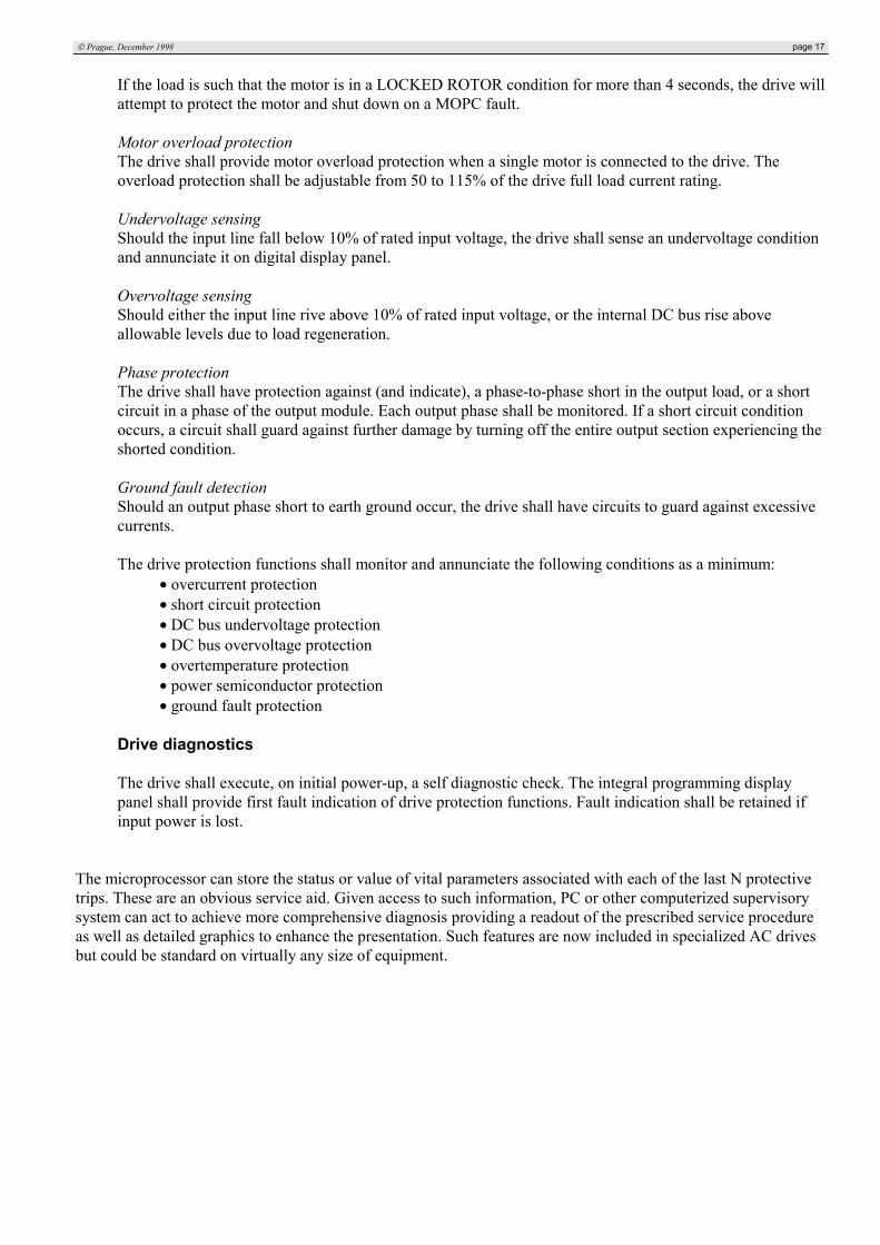
Figure 11 shows the structure of a system for fault identification through current pattern recognition [2].Including 6 free-wheeling diodes, there are 12 power devices in an inverter (Fig.3). Consideration of up to twodevices/diodes being faulty simultaneously and three unbalanced loads cases constitutes 48 faulty modes in total.Simulation studies demonstrate that each of these modes can be identified from the pattern of the 3-phase currentwaveforms. Such patterns can be described by three parameters:
• DC offset value of the phase current• polarity of the average current value in the first quarter of a complete cycle• polarity of the average current value in the second quarter of the same cycle
Each of these can be either greater than or less than or equal to zero, giving 9 logic flags per phase. Consequently,for three-phase currents there are 27 logic flags. During a faulty situation 9 of these flags will be set.
Prague, December 1998 page 21
Fig.11: Structure of on-line fault diagnosis system for VSI AC drive
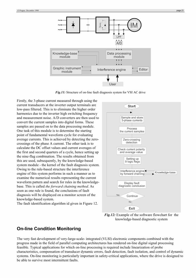
Firstly, the 3-phase current measured through using thecurrent transducers at the inverter output terminals arelow-pass filtered. This is to eliminate the higher orderharmonics due to the inverter high switching frequencyand measurement noise. A/D converters are then used toconvert the current samples into digital forms. Thesesamples are passed on to the data processing module.One task of this module is to determine the startingpoint of fundamental waveform cycle for evaluatingaverage currents. This is achieved by detecting the zero-crossings of the phase A current. The other task is tocalculate the DC offset values and current averages ofthe first and second quarters of a cycle, hence setting upthe nine-flag combination. The results obtained fromthis are used, subsequently, by the knowledge-basedsystem module - the kernel of the fault diagnosis system.Owing to the rule-based structure the interferenceengine of this system performs in such a manner as toexamine the numerical results representing the currentwaveform pattern and search for rules in the knowledge-base. This is called the forward chaining method. Assoon as one rule is found, the conclusions of faultdiagnosis will be displayed on a monitor screen of theknowledge-based system.The fault identification algorithm id given in Figure 12.
On-line Condition Monitoring
The very fast development of very-large-scale- integrated (VLSI) electronic components combined with theprogress made in the field of parallel computing architectures has rendered on-line digital signal processingfeasible. Typical applications for which on-line processing is required include linearization of probecharacteristics, compensation of transducer dynamic errors, fault detection, fault isolation, and control of dynamicsystems. On-line monitoring is particularly important in safety-critical applications, where the drive is designed tobe able to survive most intermittent faults.
Fig.12: Example of the software flowchart for theknowledge-based diagnostic system
A Brief survey of AC Drive Fault Diagnosis & Detection page 22
Some examples of On-line fault detection approaches
The paper [5] describes a measurement apparatus based on the use of two concurrent digital signal processors(DSPs). The first DSP carries out the on-line fault detection, by checking each sample of the system's actualoutput signal against the expected nominal output signal provided by a parametric model of the system. Thesecond DSP performs a real-time actual model-parameter estimation by executing a nonrecursive identificationalgorithm in order to track eventual parameter drifts established during normal operation, and in the case of a faultoccurring, to determine the fault-model parameters to be used for a subsequent fault-diagnosis phase.
In the paper [4] a diagnostic system is presented which consider the usual drive protection and consequently thevariables already at disposal. The attention is focused on the input and output variables of VSI subsystemsobtaining the following subset of reasoned monitoring nodes:
• AC power line currents• DC-link input and output current• DC-link output voltage• Inverter output currents
In this way the cost for additional voltage and current transducers is minimized. The faulty conditions was studiedby simulation and by experimental investigation and the data analysis has been performed over all the variableslisted previously via FFT algorithm.The anomalous components that arise in case of drive faults can be showed in the waveforms and spectracontents. Then the rules for knowledge base oriented to diagnostics has to be performed.
AC motor diagnosis
The basic principle for monitoring the motor for faults before motor start is to stress the motor windings withvoltage pulses and to analyze the pulse response. A running motor is monitored by detecting a change ofunbalance in the motor.
For the condition monitoring of AC machines while they are in operation, several methods have been worked out.These methods provide information about the temperature-rise of bearings, the amplitudes of their vibration andnoise. After analyzing the results of repeated vibration and noise measurements of the machine performed in welldefined intervals and comparing them to a reference level, the nature and expected date of breakdown can beestimated.
Large electromachine systems are often equipped with vibration sensors that, unfortunately, are delicate andexpensive. Therefore, intensive research efforts have recently been focused on an approach involving the motorcurrent signature analysis (MCSA).
During the past 15 years there have been significant advances in the understanding of the causes of the AC motorfault mechanisms. Of particular significance has been the research and development of new and more reliable on-line diagnostic techniques to detect the inception of these faults. The availability of powerful signal analysisinstrumentation systems has made it possible to identify unique signature patterns in the current spectrum whichare only a function of a given fault mechanism.
Motor Current Signature Analysis (MCSA)
The MCSA is used mainly to detect broken or cracked rotor bars. When bars or end rings crack or break, the flowof induced current changes, which causes abnormalities in the flux. This disturbance is defectable in the linecurrent, and manifests itself as peaks located at (1±s)f, where s is the slip of the motor, and f is the line frequency.There are other problems that result in electrical imbalance that may produce the same spectrum lines as brokenrotor bars. These may include faulty or worn bearings, or cage eccentricity. However, a true rotor problem will not
Prague, December 1998 page 23
only produce peaks near the fundamental frequency, but also around the upper harmonics as well, where mostother problems occupy only the lower part of the spectrum.Trending is essential in signature analysis. Each type of motor is unique in that the amplitude of the peaks thatoccur at suspect frequency vary, and what is normal for one motor may be indicative of severe problems inanother. Also, one major constraint is that the test only works well when motors are running close to full load.This is not always possible or practical.Even with the testing constraints, motor current signature analysis is currently the most reliable way to detectrotor faults, and quick and simple to perform. If trended properly and correlated with other techniques which mayindicate rotor problems, such vibration analysis, it may be useful.
Instantaneous stator power analysis
In the paper [7] is shown that the amount of information carried by the instantaneous stator power about irregularmechanical conditions of a drive system is higher than that deductible from the stator current only.The instantaneous stator power depends both on the amplitude and phase of the stator current.
The voltage is measured by a resistive divider, the current by a shunt (in the paper [6]), and both are fed to thesignal processing circuit. Voltage and current signals are then multiplied by an analog multiplier. This productrepresents the instantaneous power.In the case of a short circuit or an interturn short circuit, amplitude and frequency are higher. In the case of aground faults, these are lower than the quantities obtained from a healthy motor.
For complete motor protection, vibrational techniques can also be used. With this, the stator, the rotor, and thebearings can be monitored. Finally, the are mechanical methods for monitoring that analyze particles or gasesproduced by the electrical machine.
A Brief survey of AC Drive Fault Diagnosis & Detection page 24
Literature[1] Nowotny, D.W. - Lipo, T.A.: Vector Control and Dynamics of AC Drives, Oxford University Press, New
York, 1996[2] Zhang, L. - Aris, I. B. - Hulley, L. N. : A knowledge-based system for on-line fault diagnosis of power
circuits for AC machine drive, EPE’95, Seville, 1995[3] Hoadley, F.L.: AC drive systems for critical applications, Iron and Steel Engineer, Nov. 1994, p. 30-35[4] Gentile, G. - Rotondale, N.: An approach to knowledge-base representation in electric drive fault
diagnosis, IEEE PES Conference Record, 1992[5] Aldo Baccigalupi, A. - Bernieri, A. - Pietrosanto, A. : A Digital-Signal-Processor-Based Measurement
System For On-Line Fault Detection, IEEE Trans. on IE, Vol.44, No.4, August 1997[6] Maier, R. : Protection of Squirrel-Cage Induction Motor Utilizing Instantaneous Power and Phase
Information, 1990 IEEE Industry Applications Society Annual Meeting-IAS-25, p 263-267, 1990 Oct 7-12[7] Legowski, S. F. - Trzynadlowski, A. N. : Instantaneous Stator Power as a Medium for Signature Analysis
of Induction Motor, IEEE IAS Annual meeting, Orlando, USA, 1995[8] Orlowska, T. - Kowalski, C.T.: Neural network techniques in the electrical drives control and faults
detection, EDPE, Kosice, 1996[9] Kastha, D. - Bose, B. K. : Investigation of Fault Modes of Voltage-fed Inverter System for Induction Motor
Drive, IEEE Trans. on IA, Vol.30, No.4, July/August 1994[10] Lowery, T. F. - Petro, D. W. : Application Considerations for PWM Inverter-fed Low-Voltage Induction
Motors, IEEE Trans. on IA, Vol.30, No.2, March/April 1994[11] Frederick L. Hoadley, F. L. : AC drive systems for critical applications, IEEE Trans. on Instrumentation
and measurement, Vol.46, No.3, June 1997[12] Smith, K. S. - Ran, L. - Penman , J. : Detection of Intermittent Misfiring Voltage-Fed PWM Inverter
Induction-Motor Drive, IEEE Trans. on IA, Vol.28, No.2, March/April 1992[13] F. Filippetti, F. - Franceschini, G. - Tassoni, C. : Integrated Diagnostic Systems for Failure Identification
in Power Converters, ICEM’96 Proceedings, Vigo, Spain, 1996[14] Debebe, K. - Rajagopalan, V.: Expert systems for fault diagnosis of VSI fed AC drives, 1991 IEEE Industry
Applications Society Annual Meeting, Dearborn, MI, USA, 1991 Sep/Oct[15] Renfrew, A.C. - Tian, J.X.: The use of a knowledge-based system in Power electronic circuit fault
diagnosis, IEEE IAS Annual meeting, Dearborn, USA, Sept/Oct 1991[16] Debebe, K. - Rajagopalan, V.: Diagnosis and monitoring for AC drives, IEEE IAS Annual meeting,
Houston, USA, Oct.1992
Created by Petr KadaníkDecember 1998, Prague
_____________________
The Czech Technical UniversityDept.of Electrical Drives & Traction
Technická 2, K314166 27 • PRAHA 6Tel: 02/2435 2812
E-mail: [email protected]