BRC Engineering Technical Bulletin TB-BRC500-001 Rev 0
15
BRC Engineering Technical Bulletin TB-BRC500-001 Rev 0
Transcript of BRC Engineering Technical Bulletin TB-BRC500-001 Rev 0

BRC Engineering Technical Bulletin TB-BRC500-001 Rev 0

BRC Engineering Technical Bulletin TB-BRC500-002 Rev 0
Balance Shaft Additional Inner Race
The BRC500 engine kit comes with two needle bearing inner races. One is supplied with needle bearing “NA4901-XL” and one is supplied loose “Inner Race IR12x16x13”. They are both interchangeable, so don’t worry if you mix them up. The extra inner race is pressed into the right hand case when you are installing all bearings. It’s used to control the balance shaft needle bearing inner race end float. Failure to install it will result in catastrophic failure and damage to the balance shaft, balance shaft gears, engine cases, etc.
Installing the balance shaft into the cases: These steps assume that the extra supplied needle bearing inner race and the needle bearing outer race have already been installed in the right hand case. To make things easier, this step can be completed just before assembling the clutch.
1) Place the balance shaft in a freezer for 30+ minutes. 2) Heat the left side bearing pocket with a heat gun for a few minutes. 3) Quickly tap the cold balance shaft/bearing assembly into the left heated pocket using a soft
mallet until it bottoms. 4) On the opposite side, slide the remaining needle bearing inner race into the needle bearing and
over the balance shaft. 5) Install the small woodruff key. 6) Install the balance shaft gear onto with balance shaft, making sure the timing marks align with
the crank gear. 7) Install the thin washer and nut with red Loctite and tighten to 27 Nm. You can use a small
aluminum (not steel) wedge between the gears to prevent them from rotating when tightening.

BRC Engineering Technical Bulletin TB-BRC500-003 Rev 0
Kickstarter Idler Gear Retainer
The BRC500 engine kit comes with a high-strength kickstarter idler gear retainer. The KTM idler gear external retaining ring can fail due to the high force required to kickstart a 500cc engine. ALWAYS USE THE DECOMPRESSION VALVE TO PREVENT OVERLOADING THESE COMPENENTS. Failure to install this improvement or failure to use the decompression valve can result in catastrophic failure and damage to the kickstarter lever, idler gear, transmission and crankshaft gears.
Installing the retainer: Do not install the KTM idler gear post socket head cap screw or the external retaining ring! These steps assume that the idler gear post has already been installed in the right hand case. To make things easier, this step can be completed just before assembling the clutch.
1) Install the idler gear over the post. 2) Install the KTM washer onto the gear. 3) Push the black idler gear retainer into the post. 4) Install the flat head cap screw into the idler gear post using red Loctite and tighten to 10Nm. 5) Verify that the idler gear is free to spin and has slight end-float.

BRC Engineering Technical Bulletin TB-BRC500-004 Rev 0
Baseline Carburetor Settings
These settings are recommended for use with factory installed KTM PWK 36mm (and over-bored 38mm*) carburetors. These settings assume a relative air density ratio (ADR) of 88 or 1000m (3300ft), 18°C (64°F) and low humidity.
Main jet: 165
Pilot Jet: 60
Air Mixture Screw: 1/2 to 1 turn out (depends on conditions)
Needle: NZ2J (factory installed in some bikes)
Needle Clip Position: #2
Fuel: 91 octane or higher
Pre-Mix: 50:1 Motul 800 2T
*BRC Engineering can bore your factory carburetor to 38mm. Please inquire for details.

BRC Engineering Technical Bulletin TB-BRC500-005 Rev 0
Water Pump Shaft Centrifugal Weight Removal
The BRC500 uses exhaust gas pressure acting against a spring to control the power valve. This makes the KTM centrifugal power valve system, which is incorporated in the water pump shaft obsolete. BRC provides a spacer in the engine kit to help set the gear position after removing the weights.
Removing centrifugal weights from water pump shaft:
1) Support the outer edge of the gear with a metal ring.
2) Press the shaft down and out of the gear. 3) Remove the centrifugal components. The BRC500 uses the gear and shaft only.
4) Stand the shaft up with the small end pointing down. Place the gear on the shaft with the provided spacer on top of the gear.
5) Press down on the spacer and gear until it bottoms out. The spacer will set the correct gear position at 15mm from the end.

BRC Engineering Technical Bulletin TB-BRC500-005 Rev 0
6) Install the water pump bearing and shaft seal in the primary cover. Be sure to orient the seal so the numbers are facing out and the small lip spring is facing inwards.
7) Install the water pump shaft in the bearing and seal. 8) Install the water pump impeller. 9) Check for free operation of the shaft. Some drag from the seal will be felt when turning the
shaft.

BRC Engineering Technical Bulletin TB-BRC500-006 Rev 0
2012 & Prior Cultch Basket Spacer
Engines from 2012 & prior that have a six spring, multi-piece riveted clutch basket require a spacer to be installed to prevent interference with the balance shaft. A spacer will be included with your kit if you informed us that your engine was from this period. Newer engines with a diaphragm spring and one-piece clutch basket do not require this.

BRC Engineering Technical Bulletin TB-BRC500-007 Rev 0
SX Stator Cover Modification
SX Engines that don’t come equipped with an electric starter require a minor modification to the plastic stator cover. Cut a notch the cover as shown and trim the rubber grommet of the wiring harness to fit flush against the engine case.

BRC Engineering Technical Bulletin TB-BRC500-008 Rev 0
Cylinder Head Stay
NOTE: The following is only a guideline meant to steer you in the right direction. BRC is only aware of the following variations, but others may exist. At this time we have not installed an engine in every model and year. Feel free to contact us with comments relating to your application.
When installing a BRC500 into your chassis you are required to modify your existing cylinder head stay or fabricate a new one.
1) Some chassis with a non-linkage style rear suspension (PDS) can use the existing cylinder head stay by flipping it upside-down and drilling a new hole.
2) Chassis with a linkage style rear suspension will require a new stay built from 3mm (1/8”) aluminum or steel using the attached template printed at 100% scale. Some chassis don’t facilitate a rear bolt near the upper shock absorber attachment point – if that’s the case then omit it from your stay.

APP
ROM
IXA
TE C
UT L
INE
FOR
NO
REA
R M
OUN
T
1
AB
2
=
( lbs
)
E
REV
APP
RO
VAL
7
34
6
56
5
78
48
C
D
Cyl
inde
r Hea
d St
ay -
Type
1
C
DIM
ENSI
ON
S A
RE
IN IN
CH
ES, A
NG
LES
AR
E IN
DEG
REE
S
D
B
MA
TER
IAL
X.XX
XX
0.
0010
"A
F
0.00
5"
0.00
1" /
IN.
F
THE
INFO
RMA
TION
CO
NTA
INED
IN T
HIS
DRA
WIN
G IS
THE
SO
LE P
ROPE
RTY
OF
BRC
EN
GIN
EERI
NG
. AN
Y RE
PRO
DUC
TION
IN W
HOLE
OR
PART
WITH
OUT
THE
WRI
TTEN
PER
MIS
SIO
N O
F BR
C E
NG
INEE
RIN
G IS
PRO
HIBI
TED
.
WEI
GH
TD
WG
. N
O.
kg
SHEE
T 1
of 1
E
0.00
1"
0.00
1" /
IN.
BRC
Rac
ing
BRC
500x
c
=
-
SUR
FAC
E FI
NIS
H √
63µ
in.
UN
SPEC
IFIE
D C
HA
MFE
RS
& FI
LLET
RA
DII
= 0.
010"
=
0.00
1" /
IN.
=
1/64
"-
REM
OVE
ALL
BUR
RS A
ND
SHA
RP E
DGES
-
12
3
DEC
IMA
LSX.
X
0.
030"
X.XX
0.01
0"X.
XXX
FRA
CTI
ON
AL
TOLE
RA
NC
E
ENG
INEE
RIN
G
174.
96.
89
PRIN
TED
ON
08/
04/2
019
4:12
PM

BRC Engineering Technical Bulletin TB-BRC500-001 Rev 0
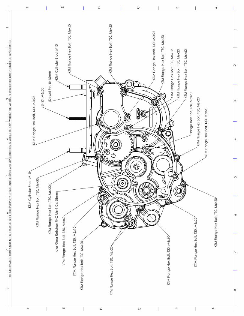
Fastener Map
The BRC500 kit is intended to re-use fasteners and dowels from your donor KTM engine. BRC provides any additional fasteners that differ. Not all fastener lengths reside in the same location, so please refer to the attached fastener maps.
As a rule of thumb, a fastener into aluminum should have approximately 2 times the diameter of the thread engaged. For example, if an M6 fastener is loosely dropped into its hole, approximately 12mm of fastener should be exposed prior to tightening. This may vary slightly based on location.
If you are missing or require additional KTM fasteners, your KTM dealer or www.specbolt.com (in the USA) can assist.

SHSS
, M6x
50
KTM
Cyl
ind
er S
tud
, M10
KTM
Cyl
ind
er S
tud
, M10
KTM
Fla
nge
Hex
Bolt,
T30
, M6x
70
KTM
Fla
nge
Hex
Bolt,
T30
, M6x
20
KTM
Fla
nge
Hex
Bolt,
T30
, M6x
40
KTM
Fla
nge
Hex
Bolt,
T30
, M6x
30
Red
uced
Hea
d H
ex B
olt,
M6x
25
Red
uced
Hea
d H
ex B
olt,
M6x
45
KTM
Fla
nge
Hex
Bolt,
T30
, M6x
20
KTM
Fla
nge
Hex
Bolt,
T30
, M6x
30
Red
uced
Hea
d H
ex B
olt,
M6x
45
Red
uced
Hea
d H
ex B
olt,
M6x
45
SHC
S M
10x1
10m
m, M
odifi
ed H
ead
Was
her -
10.
5x20
x2m
m
KTM
Fla
nge
Hex
Bolt,
T30
, M6x
40
Red
uced
Hea
d H
ex B
olt,
M6x
45
Red
uced
Hea
d H
ex B
olt,
M6x
45
Red
uced
Hea
d H
ex B
olt,
M6x
45
SHC
M6
x 1.
0 x
45m
m
SHC
M6
x 1.
0 x
70m
m
Red
uced
Hea
d H
ex B
olt,
M6x
80
Red
uced
Hea
d H
ex B
olt,
M6x
45
Dow
el P
in, 8
x16m
m
Red
uced
Hea
d H
ex B
olt,
M6x
30
KTM
Fla
nge
Hex
Bolt,
T30
, M6x
20
KTM
Fla
nge
Hex
Bolt,
T30
, M6x
60
SHC
M6
x 1.
0 x
45m
m
KTM
Fla
nge
Hex
Bolt,
T30
, M6x
40
KTM
Fla
nge
Hex
Bolt,
T30
, M6x
55
(SX:
Use
Red
uced
Hea
d B
olt)
(For
Cha
in G
uid
e, O
ther
wise
20m
m)
FHC
M6
x 18
mm
12
34
56
788
76
54
32
1
ABCDE
AF E D C B
F
THE
INFO
RMA
TION
CO
NTA
INED
IN T
HIS
DRA
WIN
G IS
THE
SO
LE P
ROPE
RTY
OF
BRC
EN
GIN
EERI
NG
. AN
Y RE
PRO
DUC
TION
IN W
HOLE
OR
PART
WITH
OUT
THE
WRI
TTEN
PER
MIS
SIO
N O
F BR
C E
NG
INEE
RIN
G IS
PRO
HIBI
TED
.
KTM
Fla
nge
Hex
Bolt,
T30
, M6x
20
KTM
Fla
nge
Hex
Bolt,
T30
, M6x
20
KTM
Fla
nge
Hex
Bolt,
T30
, M6x
10
KTM
Fla
nge
Hex
Bolt,
T30
, M6x
60
Idle
r Gea
r Ret
aine
r FHC
M6-
1.0
x 58
mm
KTM
Fla
nge
Hex
Bolt,
T30
, M6x
20
KTM
Fla
nge
Hex
Bolt,
T30
, M6x
55
KTM
Cyl
ind
er S
tud
, M10
KTM
Fla
nge
Hex
Bolt,
T30
, M6x
25
SHSS
, M6x
50
Dow
el P
in, 8
x16m
m
KTM
Cyl
ind
er S
tud
, M10
KTM
Fla
nge
Hex
Bolt,
T30
, M6x
55
KTM
Fla
nge
Hex
Bolt,
T30
, M6x
55
KTM
Fla
nge
Hex
Bolt,
T30
, M6x
25
KTM
Fla
nge
Hex
Bolt,
T30
, M6x
20
KTM
Fla
nge
Hex
Bolt,
T30
, M6x
12
KTM
Fla
nge
Hex
Bolt,
T30
, M6x
20
KTM
Fla
nge
Hex
Bolt,
T30
, M6x
60Fl
ange
Hex
Bol
t, T3
0, M
5x20
KTM
Fla
nge
Hex
Bolt,
T30
, M6x
20
KTM
Fla
nge
Hex
Bolt,
T30
, M6x
20
KTM
Fla
nge
Hex
Bolt,
T30
, M6x
20
KTM
Fla
nge
Hex
Bolt,
T30
, M6x
20
KTM
Fla
nge
Hex
Bolt,
T30
, M6x
60
12
34
56
788
76
54
32
1
ABCDE
AF E D C B
F
THE
INFO
RMA
TION
CO
NTA
INED
IN T
HIS
DRA
WIN
G IS
THE
SO
LE P
ROPE
RTY
OF
BRC
EN
GIN
EERI
NG
. AN
Y RE
PRO
DUC
TION
IN W
HOLE
OR
PART
WITH
OUT
THE
WRI
TTEN
PER
MIS
SIO
N O
F BR
C E
NG
INEE
RIN
G IS
PRO
HIBI
TED
.

Flan
ged
Hex
Bol
t Gr 1
0.9,
M8
x 25
Cop
per W
ashe
r, 8.
3 x
16.5
x 0
.9m
m
KTM
Fla
nge
Hex
Bolt,
T30
, M6x
16
SHC
M6
X 1.
0 X
20m
m
KTM
Cyl
ind
er F
lang
e He
x N
ut, M
10x1
.5
Flan
ge N
ut, M
6 N
yloc
k
12
34
56
788
76
54
32
1
ABCDE
AF E D C B
F
THE
INFO
RMA
TION
CO
NTA
INED
IN T
HIS
DRA
WIN
G IS
THE
SO
LE P
ROPE
RTY
OF
BRC
EN
GIN
EERI
NG
. AN
Y RE
PRO
DUC
TION
IN W
HOLE
OR
PART
WITH
OUT
THE
WRI
TTEN
PER
MIS
SIO
N O
F BR
C E
NG
INEE
RIN
G IS
PRO
HIBI
TED
.

BRC Engineering Technical Bulletin TB-BRC500-010 Rev 0
Engine Specifications: Bore: 89mm Stroke: 82mm Displacement: 510cc Compression Ratio: 12.5:1 Squish: 1.25mm Primary Ratio: 2.25 (72:32) Port Timings (duration): Main Ex (power valve open): 190°, 43.34mm Main Ex (power valve closed): 156°, 55.19mm Sub Ex: 175°, 48.7mm Main Trans: 116°, 67mm Sec. Trans: 117°, 66.7mm Boost: 119°, 66.2mm Fuel: Pre-Mix: 50:1, Motul 800 2T Gasoline: minimum 91 octane Quick Reference Parts List: Piston: #01-14-008, Honda CR500 standard bore (Vertex cast piston #22447) Connecting Rod: #01-11-003, Honda CR500 144mm (ProX #03.1406, Wossner # P2044) Crankshaft: #07-04-003, Three-piece with rod kit (rebuildable) Engine Gasket Kit: #07-01-031 (Cometic #C3732) Case Gasket: #07-01-008 (Cometic # EC2414020F) Primary Cover Gasket: #07-01-009 (Cometic # EC2415020F) Stator Spacer Gasket: #07-01-010 (Cometic #EC2416020F) Stator Cover Gasket: #07-01-015 (Cometic # EC2417020F) Base Gasket 0.4mm: #07-02-004 (Cometic # B1417015F) Base Gasket 0.5mm: #07-02-005 (Cometic # B1417020F) Reed Cage Gasket: #07-08-001 (Cometic # IR1578020F) Exhaust Gasket: #07-09-002 (Cometic #EX1923064AM) Exhaust Pipe: #07-09-004 (FMF # 125189) Silencer: #07-09-008 Power Core 2 (FMF #125190) Spark Arrestor Silencer: #07-09-009 Turbine Core 2 FMF (#125191) Exhaust O-Ring: 3x56mm Viton Main Bearing Kit with seals: #07-04-004 (Hot Rods # K066, ProX #23.CBS36004) Transmission Bearing Kit: #07-05-018 (Hot Rods #TBK0019) Water Pump Kit: #07-11-005 (Hot Rods #WPK0049) Output Shaft Kit: #07-05-017 (Hot Rods # OSK0011)