Brazing Saddles ( Team 15) Client: Parker-Hannifin Faculty Mentor: Dr. Kevin Kochersberger Faculty...
25
Brazing Saddles Brazing Saddles ( ( Team 15) Team 15) Client: Parker-Hannifin Client: Parker-Hannifin Faculty Mentor: Dr. Kevin Kochersberger Faculty Mentor: Dr. Kevin Kochersberger Faculty Coordinator: Dr. Paul Stiebitz Faculty Coordinator: Dr. Paul Stiebitz Preliminary Design Report Preliminary Design Report February 21 February 21 st st , 2003 , 2003 Ethan Bagley Ethan Bagley Melissa Curtin Melissa Curtin Paul Diedrich Paul Diedrich Charles Gullo Charles Gullo Fulya Tezer Fulya Tezer Tom Wild Tom Wild
-
date post
22-Dec-2015 -
Category
Documents
-
view
220 -
download
1
Transcript of Brazing Saddles ( Team 15) Client: Parker-Hannifin Faculty Mentor: Dr. Kevin Kochersberger Faculty...

Brazing SaddlesBrazing Saddles
((Team 15)Team 15)Client: Parker-HannifinClient: Parker-Hannifin
Faculty Mentor: Dr. Kevin KochersbergerFaculty Mentor: Dr. Kevin KochersbergerFaculty Coordinator: Dr. Paul StiebitzFaculty Coordinator: Dr. Paul Stiebitz
Preliminary Design ReportPreliminary Design ReportFebruary 21February 21stst, 2003, 2003
Ethan BagleyEthan Bagley
Melissa CurtinMelissa Curtin
Paul DiedrichPaul Diedrich
Charles GulloCharles Gullo
Fulya TezerFulya Tezer
Tom WildTom Wild
2
AgendaAgenda
Problem StatementProblem StatementDesign Phase 1Design Phase 1Design Phase 2Design Phase 2Plan of ActionPlan of Action

3
Problem StatementProblem Statement
• Current braze Current braze furnace process:furnace process:– Operator loads one Operator loads one
part every six part every six minutesminutes
– Operator must walk Operator must walk 40 feet to opposite 40 feet to opposite end of furnace to end of furnace to retrieve each partretrieve each part
– Part removal system Part removal system currently unreliablecurrently unreliable
4
Project GoalsProject Goals
• Design Phase 1: Part removal Design Phase 1: Part removal mechanismmechanism– Key issues:Key issues:
• Part stabilityPart stability• System autonomySystem autonomy
• Design Phase 2: Part Handling Design Phase 2: Part Handling SystemSystem– Analysis of Layout in Brazing AreaAnalysis of Layout in Brazing Area
• FlexibilityFlexibility

5
Design Phase 1:Design Phase 1:
Development of Mechanical Development of Mechanical SystemSystem
6
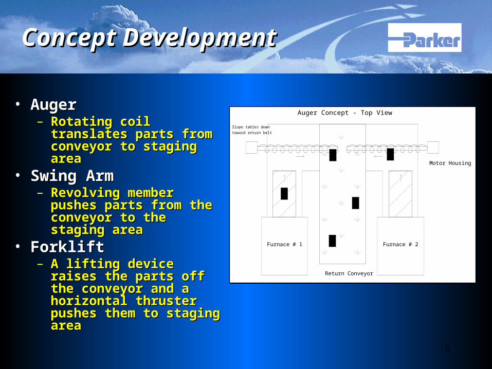
Concept DevelopmentConcept Development
• AugerAuger– Rotating coil translates Rotating coil translates
parts from conveyor to parts from conveyor to staging areastaging area
• Swing ArmSwing Arm– Revolving member Revolving member
pushes parts from the pushes parts from the conveyor to the staging conveyor to the staging areaarea
• ForkliftForklift– A lifting device raises the A lifting device raises the
parts off the conveyor parts off the conveyor and a horizontal thruster and a horizontal thruster pushes them to staging pushes them to staging areaarea
Return Conveyor
Furnace # 2Furnace # 1
Motor Housing
Auger Concept - Top View
Slope tables downtoward return belt
7
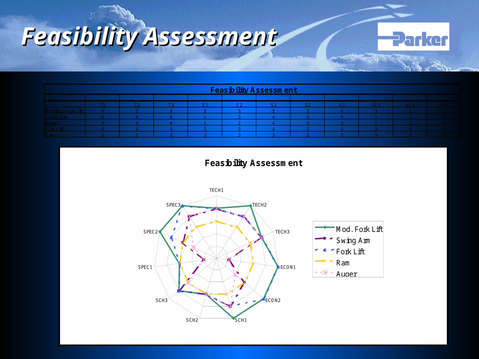
Feasibility AssessmentFeasibility Assessment
Feasibility Assessment
TECH1
TECH2
TECH3
ECON1
ECON2
SCH1SCH2
SCH3
SPEC1
SPEC2
SPEC3
Mod. Fork Lift
Swing Arm
Fork Lift
Ram
Auger
T1 T2 T3 E1 E2 S1 S2 S3 SP1 SP2 SP3Modified Fork Lift 4 5 4 5 5 5 3 4 3 5 5Swing Arm 4 4 4 1 3 4 3 4 1 3 4Auger 4 4 4 1 2 4 3 3 1 2 4Fork Lift 4 4 4 5 5 4 3 4 3 4 5Ram 3 3 3 3 3 3 3 3 3 3 3
Feasibility Assessment

8
Further Concept DevelopmentFurther Concept Development
• Original Fork Lift Original Fork Lift ConceptConcept– Interlocking perpendicular Interlocking perpendicular
pairs of forkspairs of forks– First pair raises parts off First pair raises parts off
belt verticallybelt vertically– Second pairs slides into Second pairs slides into
first and reroutes parts first and reroutes parts towards staging areatowards staging area
9
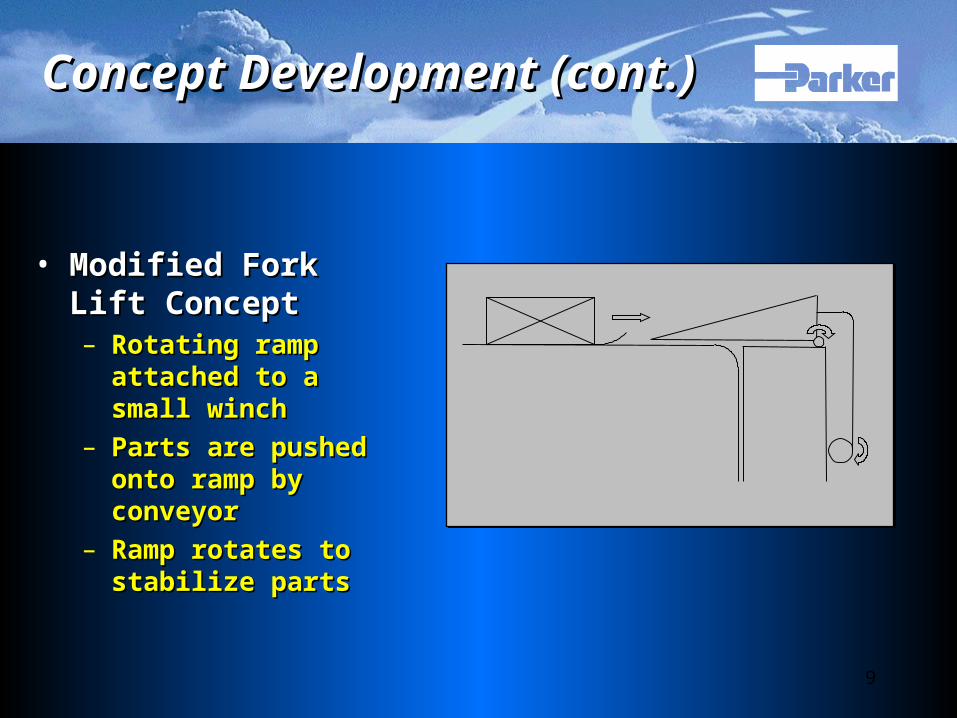
Concept Development (cont.)Concept Development (cont.)
• Modified Fork Lift Modified Fork Lift ConceptConcept– Rotating ramp attached Rotating ramp attached
to a small winchto a small winch– Parts are pushed onto Parts are pushed onto
ramp by conveyor ramp by conveyor – Ramp rotates to Ramp rotates to
stabilize partsstabilize parts
10
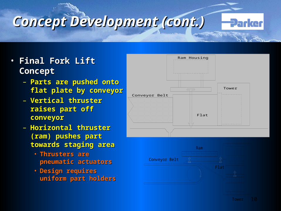
Concept Development (cont.)Concept Development (cont.)
• Final Fork Lift ConceptFinal Fork Lift Concept– Parts are pushed onto Parts are pushed onto
flat plate by conveyorflat plate by conveyor– Vertical thruster raises Vertical thruster raises
part off conveyorpart off conveyor– Horizontal thruster Horizontal thruster
(ram) pushes part (ram) pushes part towards staging areatowards staging area• Thrusters are Thrusters are
pneumatic actuatorspneumatic actuators
• Design requires Design requires uniform part holdersuniform part holders
Conveyor Belt
Flat
Tower
Ram
Conveyor Belt
Ram Housing
Tower
Flat
Stoarge Platform
11
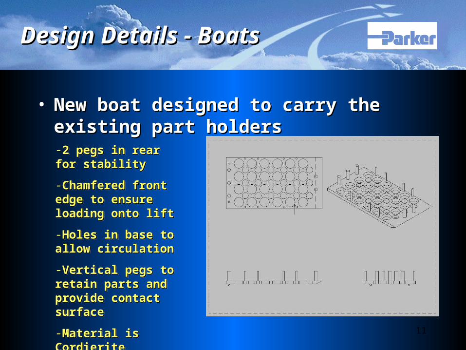
Design Details - BoatsDesign Details - Boats
• New boat designed to carry the existing New boat designed to carry the existing part holderspart holders-2 pegs in rear for 2 pegs in rear for stabilitystability
-Chamfered front edge Chamfered front edge to ensure loading onto to ensure loading onto lift lift
-Holes in base to allow Holes in base to allow circulationcirculation
-Vertical pegs to retain Vertical pegs to retain parts and provide parts and provide contact surfacecontact surface
-Material is CordieriteMaterial is Cordierite
-2 pegs in rear for 2 pegs in rear for stabilitystability
-Chamfered front edge Chamfered front edge to ensure loading onto to ensure loading onto lift lift
-Holes in base to allow Holes in base to allow circulationcirculation
-Vertical pegs to retain Vertical pegs to retain parts and provide parts and provide contact surfacecontact surface
-Material is CordieriteMaterial is Cordierite

12
Design Details - MountingDesign Details - Mounting
• The new system will be mounted using the existing bolt The new system will be mounted using the existing bolt holes in the end of the furnace tableholes in the end of the furnace table

13
Design Details - ElectricalDesign Details - Electrical
• Electrical Circuit Electrical Circuit DiagramDiagram– Design integrates Design integrates
sensor and sensor and activates the activates the mechanism when mechanism when parts are presentparts are present
14
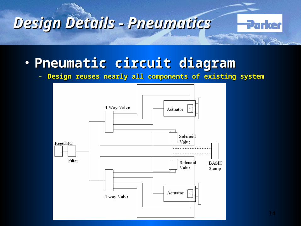
Design Details - PneumaticsDesign Details - Pneumatics
• Pneumatic circuit diagram Pneumatic circuit diagram – Design reuses nearly all components of existing systemDesign reuses nearly all components of existing system

15
Design Phase 2:Design Phase 2:
Development of Part Handling Development of Part Handling SystemSystem

16
Process FlowProcess Flow

17
Concepts ConsideredConcepts Considered
Conveyor ConceptConveyor ConceptConveyor ConceptConveyor Concept
Table ConceptTable ConceptTable ConceptTable Concept
18
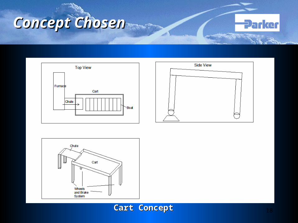
Concept ChosenConcept Chosen
Cart ConceptCart ConceptCart ConceptCart Concept
19
Time SavingsTime Savings
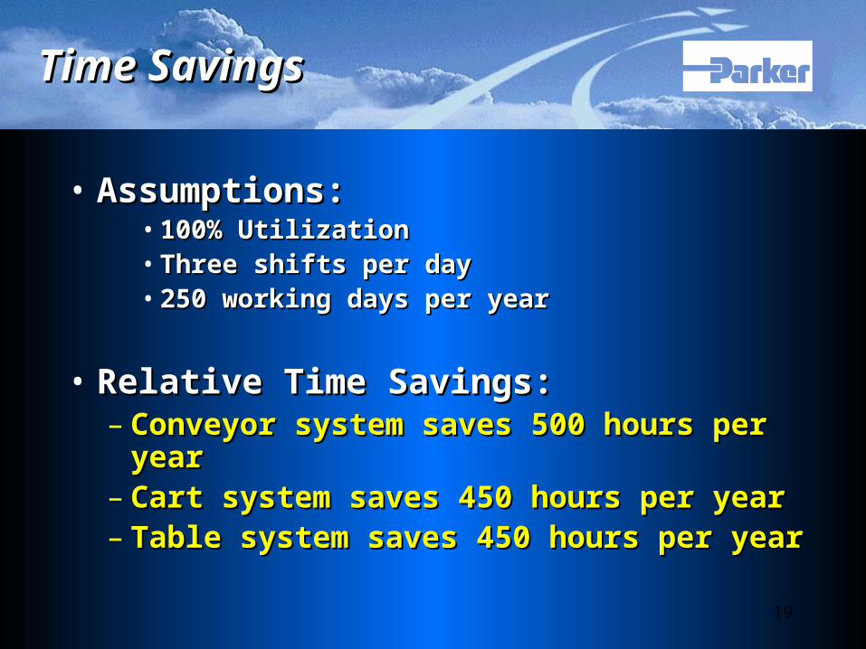
• Assumptions:Assumptions:• 100% Utilization100% Utilization• Three shifts per dayThree shifts per day• 250 working days per year250 working days per year
• Relative Time Savings:Relative Time Savings:– Conveyor system saves 500 hours per Conveyor system saves 500 hours per
yearyear– Cart system saves 450 hours per yearCart system saves 450 hours per year– Table system saves 450 hours per yearTable system saves 450 hours per year
20
Bill of Materials & CostBill of Materials & Cost
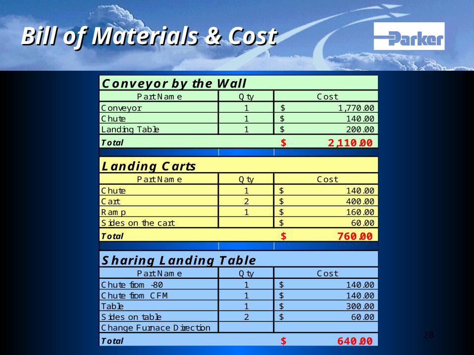
Conveyor by the WallPart Name Qty Cost
Conveyor 1 1,770.00$ Chute 1 140.00$ Landing Table 1 200.00$
Total 2,110.00$
Landing CartsPart Name Qty Cost
Chute 1 140.00$ Cart 2 400.00$ Ramp 1 160.00$ Sides on the cart 60.00$
Total 760.00$
Sharing Landing TablePart Name Qty Cost
Chute from -80 1 140.00$ Chute from CFM 1 140.00$ Table 1 300.00$ Sides on table 2 60.00$ Change Furnace Direction
Total 640.00$
21
Feasibility QuestionsFeasibility Questions
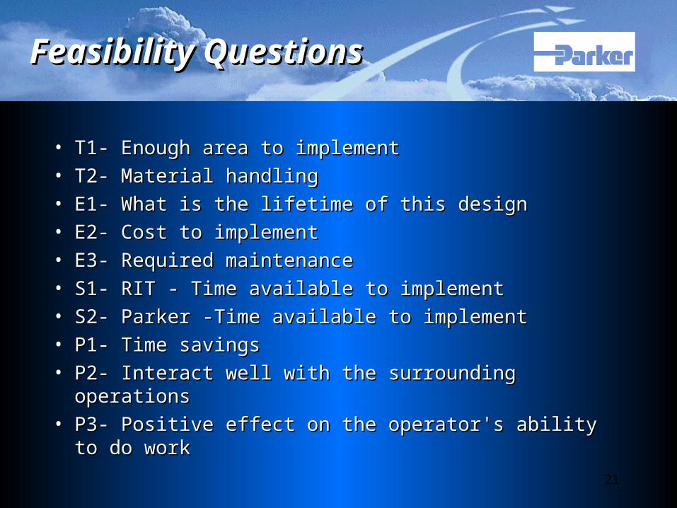
• T1- Enough area to implement T1- Enough area to implement • T2- Material handlingT2- Material handling• E1- What is the lifetime of this designE1- What is the lifetime of this design• E2- Cost to implementE2- Cost to implement• E3- Required maintenance E3- Required maintenance • S1- RIT - Time available to implement S1- RIT - Time available to implement • S2- Parker -Time available to implementS2- Parker -Time available to implement• P1- Time savingsP1- Time savings• P2- Interact well with the surrounding operationsP2- Interact well with the surrounding operations• P3- Positive effect on the operator's ability to do workP3- Positive effect on the operator's ability to do work

22
Feasibility AnalysisFeasibility Analysis
0
1
2
3T1
T2
E1
E2
E3
S1
S2
P1
P2
P3
Conveyor
Carts
Table
Baseline
T1 T2 E1 E2 E3 S1 S2 P1 P2 P3 Total
Conveyor 1 3 1 3 1 2 2 3 2 3 21Carts 2 3 2 3 2 3 3 2 2 3 25Table 1 3 2 3 2 3 3 2 1 3 23Baseline 2 2 2 2 2 2 2 2 2 2 20
23
Cart Design Cart Design
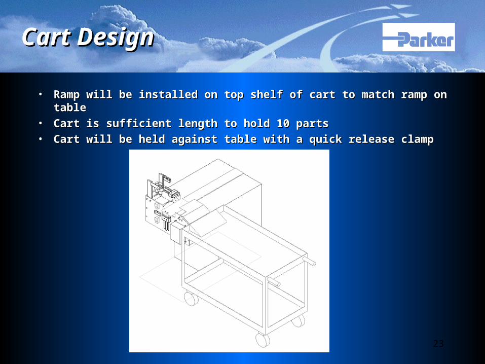
• Ramp will be installed on top shelf of cart to match ramp on tableRamp will be installed on top shelf of cart to match ramp on table
• Cart is sufficient length to hold 10 partsCart is sufficient length to hold 10 parts
• Cart will be held against table with a quick release clampCart will be held against table with a quick release clamp

24
Plan of ActionPlan of Action
• Layout & Flow AnalysisLayout & Flow Analysis
• Ergonomic & Safety AnalysisErgonomic & Safety Analysis
• Programming of Basic Stamp systemProgramming of Basic Stamp system
• Fabrication and Installation of Part Fabrication and Installation of Part Removal MechanismRemoval Mechanism
• DOE & Statistical AnalysisDOE & Statistical Analysis

25
Questions?Questions?